EP4034424B1 - Video recording mirror - Google Patents
Video recording mirrorDownload PDFInfo
- Publication number
- EP4034424B1 EP4034424B1EP20867900.1AEP20867900AEP4034424B1EP 4034424 B1EP4034424 B1EP 4034424B1EP 20867900 AEP20867900 AEP 20867900AEP 4034424 B1EP4034424 B1EP 4034424B1
- Authority
- EP
- European Patent Office
- Prior art keywords
- vehicle
- images
- processor
- video recording
- imager
- Prior art date
- Legal status (The legal status is an assumption and is not a legal conclusion. Google has not performed a legal analysis and makes no representation as to the accuracy of the status listed.)
- Active
Links
Images

Classifications
- B—PERFORMING OPERATIONS; TRANSPORTING
- B60—VEHICLES IN GENERAL
- B60R—VEHICLES, VEHICLE FITTINGS, OR VEHICLE PARTS, NOT OTHERWISE PROVIDED FOR
- B60R1/00—Optical viewing arrangements; Real-time viewing arrangements for drivers or passengers using optical image capturing systems, e.g. cameras or video systems specially adapted for use in or on vehicles
- B60R1/02—Rear-view mirror arrangements
- B60R1/04—Rear-view mirror arrangements mounted inside vehicle
- H—ELECTRICITY
- H04—ELECTRIC COMMUNICATION TECHNIQUE
- H04N—PICTORIAL COMMUNICATION, e.g. TELEVISION
- H04N5/00—Details of television systems
- H04N5/76—Television signal recording
- H04N5/765—Interface circuits between an apparatus for recording and another apparatus
- H04N5/77—Interface circuits between an apparatus for recording and another apparatus between a recording apparatus and a television camera
- B—PERFORMING OPERATIONS; TRANSPORTING
- B60—VEHICLES IN GENERAL
- B60R—VEHICLES, VEHICLE FITTINGS, OR VEHICLE PARTS, NOT OTHERWISE PROVIDED FOR
- B60R1/00—Optical viewing arrangements; Real-time viewing arrangements for drivers or passengers using optical image capturing systems, e.g. cameras or video systems specially adapted for use in or on vehicles
- B60R1/20—Real-time viewing arrangements for drivers or passengers using optical image capturing systems, e.g. cameras or video systems specially adapted for use in or on vehicles
- B60R1/22—Real-time viewing arrangements for drivers or passengers using optical image capturing systems, e.g. cameras or video systems specially adapted for use in or on vehicles for viewing an area outside the vehicle, e.g. the exterior of the vehicle
- B60R1/23—Real-time viewing arrangements for drivers or passengers using optical image capturing systems, e.g. cameras or video systems specially adapted for use in or on vehicles for viewing an area outside the vehicle, e.g. the exterior of the vehicle with a predetermined field of view
- B60R1/24—Real-time viewing arrangements for drivers or passengers using optical image capturing systems, e.g. cameras or video systems specially adapted for use in or on vehicles for viewing an area outside the vehicle, e.g. the exterior of the vehicle with a predetermined field of view in front of the vehicle
- B—PERFORMING OPERATIONS; TRANSPORTING
- B60—VEHICLES IN GENERAL
- B60R—VEHICLES, VEHICLE FITTINGS, OR VEHICLE PARTS, NOT OTHERWISE PROVIDED FOR
- B60R1/00—Optical viewing arrangements; Real-time viewing arrangements for drivers or passengers using optical image capturing systems, e.g. cameras or video systems specially adapted for use in or on vehicles
- B60R1/12—Mirror assemblies combined with other articles, e.g. clocks
- B—PERFORMING OPERATIONS; TRANSPORTING
- B60—VEHICLES IN GENERAL
- B60R—VEHICLES, VEHICLE FITTINGS, OR VEHICLE PARTS, NOT OTHERWISE PROVIDED FOR
- B60R1/00—Optical viewing arrangements; Real-time viewing arrangements for drivers or passengers using optical image capturing systems, e.g. cameras or video systems specially adapted for use in or on vehicles
- B60R1/20—Real-time viewing arrangements for drivers or passengers using optical image capturing systems, e.g. cameras or video systems specially adapted for use in or on vehicles
- B60R1/22—Real-time viewing arrangements for drivers or passengers using optical image capturing systems, e.g. cameras or video systems specially adapted for use in or on vehicles for viewing an area outside the vehicle, e.g. the exterior of the vehicle
- B60R1/23—Real-time viewing arrangements for drivers or passengers using optical image capturing systems, e.g. cameras or video systems specially adapted for use in or on vehicles for viewing an area outside the vehicle, e.g. the exterior of the vehicle with a predetermined field of view
- B60R1/26—Real-time viewing arrangements for drivers or passengers using optical image capturing systems, e.g. cameras or video systems specially adapted for use in or on vehicles for viewing an area outside the vehicle, e.g. the exterior of the vehicle with a predetermined field of view to the rear of the vehicle
- B—PERFORMING OPERATIONS; TRANSPORTING
- B60—VEHICLES IN GENERAL
- B60R—VEHICLES, VEHICLE FITTINGS, OR VEHICLE PARTS, NOT OTHERWISE PROVIDED FOR
- B60R11/00—Arrangements for holding or mounting articles, not otherwise provided for
- B60R11/04—Mounting of cameras operative during drive; Arrangement of controls thereof relative to the vehicle
- B—PERFORMING OPERATIONS; TRANSPORTING
- B60—VEHICLES IN GENERAL
- B60R—VEHICLES, VEHICLE FITTINGS, OR VEHICLE PARTS, NOT OTHERWISE PROVIDED FOR
- B60R16/00—Electric or fluid circuits specially adapted for vehicles and not otherwise provided for; Arrangement of elements of electric or fluid circuits specially adapted for vehicles and not otherwise provided for
- B60R16/02—Electric or fluid circuits specially adapted for vehicles and not otherwise provided for; Arrangement of elements of electric or fluid circuits specially adapted for vehicles and not otherwise provided for electric constitutive elements
- B60R16/03—Electric or fluid circuits specially adapted for vehicles and not otherwise provided for; Arrangement of elements of electric or fluid circuits specially adapted for vehicles and not otherwise provided for electric constitutive elements for supply of electrical power to vehicle subsystems or for
- B60R16/033—Electric or fluid circuits specially adapted for vehicles and not otherwise provided for; Arrangement of elements of electric or fluid circuits specially adapted for vehicles and not otherwise provided for electric constitutive elements for supply of electrical power to vehicle subsystems or for characterised by the use of electrical cells or batteries
- H—ELECTRICITY
- H04—ELECTRIC COMMUNICATION TECHNIQUE
- H04N—PICTORIAL COMMUNICATION, e.g. TELEVISION
- H04N23/00—Cameras or camera modules comprising electronic image sensors; Control thereof
- H04N23/50—Constructional details
- H04N23/54—Mounting of pick-up tubes, electronic image sensors, deviation or focusing coils
- H—ELECTRICITY
- H04—ELECTRIC COMMUNICATION TECHNIQUE
- H04N—PICTORIAL COMMUNICATION, e.g. TELEVISION
- H04N5/00—Details of television systems
- H04N5/38—Transmitter circuitry for the transmission of television signals according to analogue transmission standards
- H—ELECTRICITY
- H04—ELECTRIC COMMUNICATION TECHNIQUE
- H04N—PICTORIAL COMMUNICATION, e.g. TELEVISION
- H04N7/00—Television systems
- H04N7/18—Closed-circuit television [CCTV] systems, i.e. systems in which the video signal is not broadcast
- H—ELECTRICITY
- H04—ELECTRIC COMMUNICATION TECHNIQUE
- H04N—PICTORIAL COMMUNICATION, e.g. TELEVISION
- H04N7/00—Television systems
- H04N7/18—Closed-circuit television [CCTV] systems, i.e. systems in which the video signal is not broadcast
- H04N7/188—Capturing isolated or intermittent images triggered by the occurrence of a predetermined event, e.g. an object reaching a predetermined position
- B—PERFORMING OPERATIONS; TRANSPORTING
- B60—VEHICLES IN GENERAL
- B60R—VEHICLES, VEHICLE FITTINGS, OR VEHICLE PARTS, NOT OTHERWISE PROVIDED FOR
- B60R1/00—Optical viewing arrangements; Real-time viewing arrangements for drivers or passengers using optical image capturing systems, e.g. cameras or video systems specially adapted for use in or on vehicles
- B60R1/12—Mirror assemblies combined with other articles, e.g. clocks
- B60R2001/1253—Mirror assemblies combined with other articles, e.g. clocks with cameras, video cameras or video screens
- B—PERFORMING OPERATIONS; TRANSPORTING
- B60—VEHICLES IN GENERAL
- B60R—VEHICLES, VEHICLE FITTINGS, OR VEHICLE PARTS, NOT OTHERWISE PROVIDED FOR
- B60R11/00—Arrangements for holding or mounting articles, not otherwise provided for
- B60R2011/0001—Arrangements for holding or mounting articles, not otherwise provided for characterised by position
- B60R2011/0003—Arrangements for holding or mounting articles, not otherwise provided for characterised by position inside the vehicle
- B60R2011/0026—Windows, e.g. windscreen
- B—PERFORMING OPERATIONS; TRANSPORTING
- B60—VEHICLES IN GENERAL
- B60R—VEHICLES, VEHICLE FITTINGS, OR VEHICLE PARTS, NOT OTHERWISE PROVIDED FOR
- B60R11/00—Arrangements for holding or mounting articles, not otherwise provided for
- B60R2011/0001—Arrangements for holding or mounting articles, not otherwise provided for characterised by position
- B60R2011/0003—Arrangements for holding or mounting articles, not otherwise provided for characterised by position inside the vehicle
- B60R2011/0028—Ceiling, e.g. roof rails
- B—PERFORMING OPERATIONS; TRANSPORTING
- B60—VEHICLES IN GENERAL
- B60R—VEHICLES, VEHICLE FITTINGS, OR VEHICLE PARTS, NOT OTHERWISE PROVIDED FOR
- B60R2300/00—Details of viewing arrangements using cameras and displays, specially adapted for use in a vehicle
- B60R2300/10—Details of viewing arrangements using cameras and displays, specially adapted for use in a vehicle characterised by the type of camera system used
- B60R2300/105—Details of viewing arrangements using cameras and displays, specially adapted for use in a vehicle characterised by the type of camera system used using multiple cameras
- B—PERFORMING OPERATIONS; TRANSPORTING
- B60—VEHICLES IN GENERAL
- B60R—VEHICLES, VEHICLE FITTINGS, OR VEHICLE PARTS, NOT OTHERWISE PROVIDED FOR
- B60R2300/00—Details of viewing arrangements using cameras and displays, specially adapted for use in a vehicle
- B60R2300/40—Details of viewing arrangements using cameras and displays, specially adapted for use in a vehicle characterised by the details of the power supply or the coupling to vehicle components
- B60R2300/404—Details of viewing arrangements using cameras and displays, specially adapted for use in a vehicle characterised by the details of the power supply or the coupling to vehicle components triggering from stand-by mode to operation mode
- H—ELECTRICITY
- H04—ELECTRIC COMMUNICATION TECHNIQUE
- H04N—PICTORIAL COMMUNICATION, e.g. TELEVISION
- H04N23/00—Cameras or camera modules comprising electronic image sensors; Control thereof
- H04N23/60—Control of cameras or camera modules
- H04N23/65—Control of camera operation in relation to power supply
- H—ELECTRICITY
- H04—ELECTRIC COMMUNICATION TECHNIQUE
- H04N—PICTORIAL COMMUNICATION, e.g. TELEVISION
- H04N23/00—Cameras or camera modules comprising electronic image sensors; Control thereof
- H04N23/90—Arrangement of cameras or camera modules, e.g. multiple cameras in TV studios or sports stadiums
Definitions
- This disclosurerelates generally to video recording systems for vehicles, and in particular, to video recording systems to be integrated with rearview mirror assemblies in vehicles.
- Dashboard camerasare camera systems that may be adhered either to a dashboard or to a windshield of a vehicle. Dashboard cameras are designed to record events occurring in or around a vehicle. In particular, they are useful in the event of an accident, as they may provide indications of what may have transpired. They may also enable users to review and/or track the driving habits of drivers of the vehicle such as parents monitoring driving of a newly-licensed teen driver. As dashboard camera technology improves, dashboard cameras, or dash cams, are becoming more ubiquitous.
- dashboard camerassuffer from several shortcomings. For example, those that are adhered to a dashboard may have a relatively low point of view. This may mean that the dashboard camera does not capture some important details of the scene outside the vehicle. Some dashboard-mounted cameras may receive power from a cord that runs to the camera from a port in the vehicle which may be unsightly and inconvenient. In some cases, dashboard-mounted cameras may be able to be hardwired to the vehicle, but that may be costly.
- Dashboard cameras adhered to a windshieldmay provide users with a higher point of view. However, power must be supplied to the dashboard camera, either via a power cord or from a battery. For dashboard cameras that receive power from a power cord, the power cord may extend from a port in the vehicle to the windshield-mounted camera, thereby causing an obstructed view and a potential distraction. Battery-powered dashboard cameras may stop working when the battery runs out, and thus may be less reliable. Some windshield-mounted dashboard cameras may be capable of being hard-wired into the vehicle, but that may be costly.
- dashboard camerasthere may be legal issues surrounding dashboard cameras. Some states prohibit mounting devices that may obstruct a driver's view on a vehicle windshield or dashboard, thereby effectively banning after-market windshield- and dashboard-mounted dashboard cameras in those states.
- WO 2018/195671 A1discloses a rear view mirror assembly for a vehicle comprising: a housing; a display element; a mirror element supported by the housing; and a processor disposed on a printed circuit board and at least partially enclosed within the housing; wherein the processor is configured to be in communication with and to receive inputs from at least one imager; wherein at least a portion of the display element is configured to selectively display images captured by the at least one imager; wherein the at least one imager is disposed in a vehicle; and wherein at least one imager is configured to capture images from the exterior of the vehicle.
- video recording system for a vehicleis defined in claim 1.
- the first imagermay be disposed in a vehicle, and the first imager may be configured to capture images of scenes to the front of the vehicle and to transmit data on the captured images to the processor.
- the first imagermay be a wide-angle imager.
- the first imagermay be disposed on one of a headliner of a vehicle and a windshield of a vehicle.
- the video recording systemfurther may comprise a second imager in communication with the processor.
- the second imagermay be disposed in a vehicle and may be configured to capture images to the rear of the vehicle and to transmit data on the captured images to the processor. Upon a determination that there may be not sufficient memory to store new images, the system may be configured to store new images over older images.
- the rearview mirror assemblyfurther may comprise a display element, and at least a portion of the display element may be configured to selectively display images captured by one of the first and the second imagers.
- the video recording systemmay be configured to receive power from a vehicle power supply.
- the video recording systemmay be configured to be activated upon the vehicle ignition being turned on, and the video recording system may be configured to be turned off upon one of the vehicle ignition being turned off and power to the vehicle accessories being turned off.
- the video recording systemfurther may comprise a back-up battery; the back-up battery may be capable of providing sufficient power to allow the video recording system to save any images captured after power to the video recording system may be turned off.
- the user interfacemay be capable of, upon receipt of a user input, saving images captured within a predetermined time interval prior to the receipt of the user input.
- the rearview mirror assembly of the video recording systemmay comprise a display element, and at least a portion of the display element may be configured to selectively display images captured by the first imager.
- the video recording systemfurther may comprise at least one indicator disposed so as to be selectively visible through the mirror element.
- the indicatormay be configured to indicate a status of the video recording system.
- the video recording systemmay be capable of transmitting captured images wirelessly to another device.
- the video recording systemfurther may comprise a microphone in communication with the processor, and the microphone may be configured to capture audio.
- the video recording systemmay be in communication with accident detection system(s) of vehicle; and the video recording system may be configured to automatically, upon receipt of an input from the accident detection system(s) that an accident may have been detected, save images captured for a predetermined amount of time prior to the receipt of the input.
- the video recording systemfurther may comprise an accident-detection sensor configured to be in communication with the processor.
- the video recording systemmay be configured to automatically, upon receipt of an input that an accident may have occurred, save images captured for a predetermined amount of time prior to the receipt of the input.
- the video recording systemfurther may comprise a heat sink disposed within the rearview mirror assembly and a thermally conductive spacer disposed between the heat sink and the processor and configured to transfer heat from the processor to the heat sink.
- a rearview mirror assembly for a vehiclemay comprise a housing; a mirror element supported by the housing; and a processor disposed on a printed circuit board, the printed circuit board at least partially enclosed within the housing.
- the processormay be configured to be in communication with and to receive inputs from at least one imager.
- the at least one imagermay be disposed in a vehicle. At least one imager may be configured to capture images from the exterior of the vehicle.
- the captured imagesmay comprise video images.
- At least one imagermay be configured to capture images of scenes to the front of the vehicle and to transmit image data from the captured images to the processor.
- the at least one imagermay be disposed on one of a headliner of a vehicle and a windshield of a vehicle.
- the processormay be configured to be in communication and may be configured to receive inputs from at least two imagers.
- a first imagermay be disposed in the vehicle and may be configured to capture images of scenes to the front of the vehicle.
- a second imagermay be disposed in the vehicle. The second imager may be configured to capture images to the rear of the vehicle.
- the first and the second imagersmay be configured to transmit data on the captured images to the processor.
- the systemUpon a determination that there may not insufficient memory to allow newly-captured images to be stored, the system may be configured to store the new images over older images and to erase the older images.
- the processor and the at least one imagermay be configured to be activated upon the vehicle ignition being turned on, and the processor and the at least one imager may be configured to be turned off upon one of the vehicle ignition being turned off and power to the vehicle accessories being turned off.
- the processormay be capable of transmitting captured images wirelessly to another device.
- the rearview mirror assemblymay be configured to receive power from a vehicle power supply.
- the rearview mirror assemblyfurther may comprise a back-up battery.
- the back-up batterymay be capable of providing sufficient power to allow the processor to cause any captured images not saved before the power to the video recording system is turned off to be saved.
- the rearview mirror assemblyfurther may comprise a user interface capable of, upon receipt of a user input, causing the saving of images captured within a predetermined time interval prior to the receipt of the user input.
- the rearview mirror assemblyfurther may comprise a display element, and at least a portion of the display element may be configured to selectively display images captured by the at least one imager.
- the rearview mirror assemblyfurther may comprise at least one indicator disposed so as to be selectively visible through the mirror element.
- the rearview mirror assemblyfurther may comprise a microphone in communication with the processor, the microphone may be configured to capture audio.
- the rearview mirror assemblymay be in communication with accident detection systems of vehicle; and the video recording system may be configured to automatically, upon receipt of an indication that an accident may have been detected, save images captured for a predetermined amount of time prior to accident.
- the rearview mirror assemblyfurther may comprise an accident-detection sensor configured to be in communication with the processor.
- the processormay be configured to automatically, upon receipt of an input from the accident-detection sensor that an accident may have occurred, save images captured for a predetermined amount of time prior to the receipt of the input.
- the rearview mirror assemblyfurther may comprise a heat sink disposed within the rearview mirror assembly and a thermally conductive spacer disposed between the heat sink and the processor and configured to transfer heat from the processor to the heat sink.
- Video recording system 10comprises a processor 20, and at least a first camera or other imager 24 capable of being in communication with processor 20.
- Processor 20is disposed in a rearview mirror assembly 28 of the vehicle.
- Rearview mirror assembly 28further comprises a housing 32, as shown in FIG. 2 .
- a printed circuit board (PCB) 36is disposed within housing 32, and processor 20 is disposed on PCB 36.
- housing 32supports a mirror element 40.
- Mirror element 40may be configured to allow a driver of a vehicle to see objects or scenes behind the vehicle when rearview mirror assembly 28 is mounted on a windshield of a vehicle.
- rearview mirror assembly 28may further comprise an electro-optic element 48.
- Mirror element 40may be disposed between electro-optic element 48 and a support plate 44.
- Support plate 44may be disposed between mirror element 40 and PCB 36.
- mirror elementmay comprise a display element such as a liquid crystal display.
- First camera or imager 24may be disposed within or secured to an interior or exterior surface of the vehicle. First imager 24 may be disposed in a location remote from rearview mirror assembly 28. In some embodiments, first imager 24 may be disposed at the top of the vehicle windshield, adjacent to or within a headliner of a vehicle ceiling, or on a ceiling console. In some embodiments, first imager 24 may be disposed within rearview mirror assembly 28. Housing 32 of rearview mirror assembly 28 may define an imager opening (not shown). First imager 24 may be configured to capture an image of a scene to the exterior of housing 32 through imager opening.
- First imager 24may be disposed so as to be capable of capturing images of an area in front of first imager 24.
- First imager 24is capable of capturing video images.
- First imager 24may have a wide-angle lens having a wide field of view.
- First imager 24is in electrical communication with processor 20. Data from images captured by first imager 24 may be sent directly to processor 20 for processing.
- housing 32defines an opening 52 configured to allow a removable media storage card 56 to be inserted into rearview mirror assembly 28.
- media storage card 56may be placed in selective communication with processor 20.
- Media storage card 56may comprise non-volatile storage, and may comprise one of a secure digital card (SD card), a mini SD card, a microSD card, multimedia storage cards, and the like.
- SD cardsecure digital card
- mini SD cardmini SD card
- microSD cardmicroSD card
- multimedia storage cardsand the like.
- processor 20 of rearview mirror assembly 28additionally or alternatively comprises a memory 62.
- Memory 62is disposed on PCB 36.
- Memory 62may be random access memory, read only memory, flash memory, hard disk storage, flash memory storage, solid state drive memory, and the like.
- Memory 62may be non-removable from rearview mirror assembly.
- Data from captured imagesmay be stored in memory 62.
- the datamay be accessible or downloadable by a wired or wireless connection between video recording system 10 and a remote device, such as a user's mobile telephone, a laptop, or a tablet computer.
- the datamay be accessed, viewed, and/or downloaded via a wireless connection such as Bluetooth ® , Wi-Fi, or radio frequency communication.
- a usermay connect a wired connector to a dedicated port (not shown) defined in housing 32 of rearview mirror assembly 28.
- the dedicated portmay be configured to accept the wired connection to enable a user to access, view, or download data from captured images.
- imagesmay be transmitted directly to a user's account, and the user may view the images contemporaneously.
- a parentmay be able to monitor a child's driving by viewing images from a remote device such as a mobile telephone, computer, or smart television as they are generated.
- PCB 36may be configured to hold media storage card 56 when media storage card 56 is inserted into rearview mirror assembly 28.
- a secondary PCB 60may be configured to hold media storage card 56.
- Secondary PCB 60may be configured to be in communication with PCB 36.
- secondary PCB 60may be directly connected to PCB 36.
- secondary PCB 60may be connected to PCB 36 via a cable, harness or other wiring (not shown).
- Data from images captured by first imager 24may be transmitted from imager 24 to processor 20 for processing. After data from the images has been processed by processor 20, the data may be transmitted to media storage card 56 or memory 62 for storage.
- Media storage card 56may be capable of being removed from rearview mirror assembly 28 by a user, thereby allowing the user to view captured and stored images. Images may be viewed on a device that is compatible with media storage card 56 and is capable of displaying images. Data on images from media storage card 56 may be downloaded to and saved on remote devices such as mobile telephones, laptop computers, or tablet computers. Similarly, a user may view, transmit, and/or download images stored on memory 62. Images may be downloaded or transmitted to or viewed on rearview mirror assembly 28, or a remote device such as a mobile telephone, a computer, or a smart television.
- Video recording system 10may be configured to be activated upon the vehicle being turned on or the ignition of the vehicle being started. In some embodiments, once video recording system 10 has been activated, first imager 24 may begin capturing images. In some embodiments, first imager 24 may begin capturing images once a particular event has occurred. The particular event may be, for example, putting the vehicle into a forward gear or interacting with a user interface 76 of video recording system 10.
- Powermay be supplied to video recording system 10 by a power supply 72 associated with the vehicle.
- vehicle recording system 10may be configured to turn off after the vehicle ignition and/or power to the vehicle accessories is turned off.
- video recording system 10may continue to operate until the occurrence of a particular event or for a predetermined period of time after the vehicle ignition and/or power to vehicle accessories is turned off.
- rearview mirror assembly 28may further comprise a battery 74.
- Battery 74may be configured to provide power to video recording system 10 upon power from the vehicle 10 being turned off.
- Battery 74may be capable of providing sufficient power to allow video recording system 10 to save any images captured and not stored prior to the receipt, by video recording system 10, of an indication to turn off.
- rearview mirror assembly 28may comprise a capacitor, supercapacitor, solar cell, or other energy storage device (not shown) to provide power to the system, especially after the vehicle power supply has been disrupted or stopped.
- other energy storage devicesmay be configured to provide the power necessary to save data related to images that have not yet been saved in the event that power to video recording system 10 is turned off prior to all recently-captured images being saved.
- the saved imagesmay be saved in memory 62 or on media storage card 56.
- the saved imagesmay additionally or alternatively be transmitted to cloud storage or may be displayed on rearview mirror assembly 28 or on an external device such as a smart phone or computer. Once stored, the saved images may be transmitted to an external device or displayed at a user's convenience.
- Video recording system 10may further comprise a user interface 76.
- User interface 76may be disposed on rearview mirror assembly 28 or may be located remotely from rearview mirror assembly 28.
- user interface 76may comprise a plurality of buttons mounted on housing 32 or elsewhere on rearview mirror assembly 28.
- user interfaceadditionally or alternatively may be accessed through a program accessible through a remote device 78 such as a user's mobile telephone, laptop computer, or tablet computer.
- User interface 76may be configured to allow users to save particular images or images captured during a particular time period. For example, user interface 76 may, upon receipt of an appropriate user input, cause recently-recorded images to be placed in a saved status in media storage card 56 or memory 62.
- the saved imagesmay include images recorded over a certain time interval, such as images recorded in the two minutes just prior to the receipt of the user input.
- user interface 76may allow a user, upon receipt of an appropriate user input, to display images.
- rearview mirror assembly 28comprises a display element 80.
- Display element 80may be capable of selectively displaying digital images.
- display element 80may comprise a liquid crystal display.
- captured imagesmay be displayed on at least a portion 82 of display element 80 of rearview mirror assembly 28, as shown in FIG. 5B .
- a menu for controlling video playback and the likemay be selectively displayed on at least a portion of display element 80.
- video recording system 10may be capable of transmitting captured images and audio to another device such as a user's mobile telephone, laptop, or tablet computer.
- the transmission of the captured imagesmay be done wirelessly or via a wired connection.
- Video recording system 10may utilize Bluetooth ® , Wi-Fi, radio frequency communication or combinations thereof.
- images captured by video recording system 10may be displayed on a user's mobile telephone or computer.
- the transmitted imagesmay also be downloaded to and saved on a remote device such as a user's mobile telephone or computer.
- video recording system 10may further comprise at least one indicator 84 as shown in FIG. 5A .
- the at least one indicator 84may comprise, for example, a light source such as a light emitting diode (LED).
- the at least one indicator 84may be capable of selectively illuminating and of being seen through mirror element 40 of rearview mirror assembly 28.
- the at least one indicator 84may be configured to indicate to the user a status of video recording system 10, such as that video recording system 10 is actively recording or that a save request was successful.
- opening 52 in housing 32is disposed on or toward one side of rearview mirror assembly 28, and processor 20 is disposed on the opposite side.
- opening 52may be disposed toward the right side of housing 32 and processor 20 may be disposed within housing 32 toward the left side of rearview mirror assembly 28.
- This arrangementwith the heat-generating processor 20 disposed at a distance from the location of media storage card 56, may reduce the amount of heat that media storage card 56 is exposed to.
- memory 62may be disposed on the opposite side of housing 32 from processor 20, thereby reducing the amount of heat that memory 62 is exposed to.
- a heat sink 88may be disposed within housing 32 proximate to processor 20.
- a spacer 92 of thermally conductive materialmay connect processor 20 to heat sink 88.
- Spacer 92may comprise silicon or other conductive material, and may be capable of conducting heat generated by processor 20 to heat sink 88 for dissipation.
- a PCB holder 94may be disposed within housing 32 and be configured to hold secondary PCB 60.
- PCB holder 94may be of a plastic or other low- or non-thermally-transmitting material.
- PCB holder 94may act to provide a layer of insulation between media storage card 56 and PCB 36, thereby reducing the amount of heat that media storage card 56 is exposed to.
- secondary PCB 60may be disposed directly on PCB 36.
- video recording system 10may further comprise a microphone or other audio input device 96.
- Microphone 96may be in communication with processor 20 and with media storage card 56.
- Microphone 96may be configured to capture audio from within the cabin of the vehicle or from the exterior of the vehicle.
- Microphone 96may be configured to transmit the captured audio to media storage device 56 or memory 62 for storage. The captured audio may be linked with stored video.
- video recording system 10may be in communication with the accident detection system(s) of the vehicle.
- the accident detection systemsmay include, for example, accelerometers or devices that determine whether airbags have been deployed.
- video recording system 10may be configured to cause processor 20 to save recently captured images.
- the saved imagesmay be from a predetermined amount of time prior to the receipt of the indication of the accident, and may extend at least through the time at which video recording system 10 received the indication of the accident. This may give users an opportunity to access images of the events that preceded the accident.
- an accident-detection sensor(not shown) may be disposed within rearview mirror assembly 28.
- the accident-detection sensormay comprise, for example, an accelerometer.
- Video recording system 10may be in communication with the accident-detection sensor. Upon receipt of an input from the accident-detection sensor that an accident may have occurred, video recording system 10 may be configured to cause processor 20 to save recently captured images covering a predetermined period of time, thereby providing users with images of events leading up to the incident that triggered the accident-detection sensor to indicate that an accident occurred.
- video recording system 10may comprise at least a second camera or imager 64.
- Second imager 64may be disposed within or secured to the vehicle. Second imager 64 may be disposed so as to have a field of view that enables it to capture images from the rear of the vehicle. Second imager 64 may have a wide-angle field of view. Second imager 64 may be in electrical communication with processor 20. Images captured by second imager 64 may be transmitted to processor 20 for processing, and data from images may then be transmitted to media storage card 56 or memory 62 for storage. More than two imagers may be used to capture images exterior to the vehicle and still remain within the scope of this disclosure. This may include imagers disposed to capture images to the side(s) of the vehicle, imagers to capture images at angles from the vehicle, and imagers to capture images above the vehicle.
- Rearview mirror assembly 28may be mounted to a windshield or ceiling of the vehicle by a mounting element 68.
- Mounting element 68may define a channel 70 through which wires (not shown) may extend.
- the wiresmay connect at least one imager 24, 64 with processor 20, transmitting data from images captured by the at least one imager 24, 64 to processor 20.
- Media storage card 56may be configured to hold a certain amount of data. For example, media storage card 56 may be configured to hold data covering ninety minutes of images. If a determination is made that media storage card 56 does not have sufficient remaining storage to store additional images, data will be stored over existing images, thereby erasing the previously-stored images. In general, the erased images will be the oldest stored images. However, images that are in a saved status will not be erased until the occurrence of a predetermined event, such as the receipt of a particular user input or the passage of a predetermined amount of time.
- a predetermined eventsuch as the receipt of a particular user input or the passage of a predetermined amount of time.
- the rearview mirror assembly 28 of this disclosuremay include an electro-optic rearview assembly.
- Rearview mirror assembly 28may alternatively include a prismatic mirror.
- Rearview mirror assembly 28may additionally or alternatively include an electronic display that displays an image as sensed by a rearward facing camera or other imaging system (see, for example, commonly assigned U.S. Pat. No. 6,550,949 entitled “SYSTEMS AND COMPONENTS FOR ENHANCING REAR VISION FROM A VEHICLE,” filed on Sep. 15, 1998, by Frederick T. Bauer et al .).
- rearview mirror assembly 28may include both an electro-optic rearview assembly and a display device for providing an image from a rearward facing camera or other imaging system.
- a method for capturing and storing images, including video images, exterior to a vehiclemay include activating video recording system 10 upon the turning on of the vehicle. Once video recording system 10 has been activated, at least one imager 24, 64 may begin capturing images of scenes exterior to the vehicle. In some embodiments, at least one additional imager (not shown) may be configured to capture images of the interior of the vehicle. Data from the captured images may be transmitted to a processor 20 disposed within a rearview mirror assembly 28 of the vehicle. Processor 20 may be configured to process the data from the captured images.
- Video recording system 10further comprises a memory 56, 62.
- Memory 56, 62may be permanent memory 62 or removable memory 56.
- Processor 20may be configured to determine whether there is sufficient storage in memory 56, 62 to store the data from the newly-captured images. Upon a determination that there is insufficient data, processor 20 may direct the data from the newly-captured images be written over the data from the oldest images in memory 56, 62 that are not in a saved status. Processor 20 then transmits the data to memory 56, 62 for storage.
- imagesmay be put into a saved status upon the receipt from the vehicle's accident-detection system of an indication that an accident may have occurred.
- video recording system 10may comprise an accident-detection sensor, and images may be put into a saved status upon the receipt from the video recording system's accident-detection sensor of an indication that an accident may have occurred.
- video recording system 10may cause the saving of images captured for a predetermined interval prior to the receipt of the indication that an accident may have occurred by putting the images in a saved status.
- a usermay indicate through user interface 76 that the user desires images be saved.
- video recording system 10may receive, through user interface 76, an input indicating that images should be saved.
- processor 20may place images captured within a predetermined period of time, such as the ninety seconds prior to the receipt of the input, into a saved status.
- Images in a saved statusmay remain in the saved status until the receipt of a user input indicating that the particular saved images no longer need to be in a saved status and may be over-written with new images. This may be done by a user after viewing the image in the saved status.
- images in a saved statusmay be removed from a saved status after the occurrence of a predetermined event.
- the predetermined eventmay include the passage of a predetermined period of time, such as one year.
- relational termssuch as first and second, top and bottom, front and back, left and right, vertical, horizontal, and the like, are used solely to distinguish one entity or action from another entity or action, without necessarily requiring or implying any actual such relationship, order, or number of such entities or actions. These terms are not meant to limit the element which they describe, as the various elements may be oriented differently in various applications. Furthermore, it is to be understood that the device may assume various orientations and step sequences, except where expressly specified to the contrary. It is also to be understood that the specific devices and processes illustrated in the attached drawings and described in the following specification are simply exemplary embodiments of the inventive concepts defined in the appended claims. Hence, specific dimensions and other physical characteristics relating to the embodiments disclosed herein are not to be considered as limiting, unless the claims expressly state otherwise.
- the term "and/or,” when used in a list of two or more items,means that any one of the listed items can be employed by itself, or any combination of two or more of the listed items can be employed.
- the compositioncan contain A alone; B alone; C alone; A and B in combination; A and C in combination; B and C in combination; or A, B, and C in combination.
Landscapes
- Engineering & Computer Science (AREA)
- Multimedia (AREA)
- Mechanical Engineering (AREA)
- Signal Processing (AREA)
- Time Recorders, Dirve Recorders, Access Control (AREA)
- Closed-Circuit Television Systems (AREA)
- Television Signal Processing For Recording (AREA)
Description
- This application claims the benefit of and priority to
U.S. Provisional Patent Application No. 62/907,040, filed on September 27, 2019 - This disclosure relates generally to video recording systems for vehicles, and in particular, to video recording systems to be integrated with rearview mirror assemblies in vehicles.
- Dashboard cameras are camera systems that may be adhered either to a dashboard or to a windshield of a vehicle. Dashboard cameras are designed to record events occurring in or around a vehicle. In particular, they are useful in the event of an accident, as they may provide indications of what may have transpired. They may also enable users to review and/or track the driving habits of drivers of the vehicle such as parents monitoring driving of a newly-licensed teen driver. As dashboard camera technology improves, dashboard cameras, or dash cams, are becoming more ubiquitous.
- However, current dashboard cameras suffer from several shortcomings. For example, those that are adhered to a dashboard may have a relatively low point of view. This may mean that the dashboard camera does not capture some important details of the scene outside the vehicle. Some dashboard-mounted cameras may receive power from a cord that runs to the camera from a port in the vehicle which may be unsightly and inconvenient. In some cases, dashboard-mounted cameras may be able to be hardwired to the vehicle, but that may be costly.
- Dashboard cameras adhered to a windshield may provide users with a higher point of view. However, power must be supplied to the dashboard camera, either via a power cord or from a battery. For dashboard cameras that receive power from a power cord, the power cord may extend from a port in the vehicle to the windshield-mounted camera, thereby causing an obstructed view and a potential distraction. Battery-powered dashboard cameras may stop working when the battery runs out, and thus may be less reliable. Some windshield-mounted dashboard cameras may be capable of being hard-wired into the vehicle, but that may be costly.
- Additionally, there may be legal issues surrounding dashboard cameras. Some states prohibit mounting devices that may obstruct a driver's view on a vehicle windshield or dashboard, thereby effectively banning after-market windshield- and dashboard-mounted dashboard cameras in those states.
WO 2018/195671 A1 discloses a rear view mirror assembly for a vehicle comprising: a housing; a display element; a mirror element supported by the housing; and a processor disposed on a printed circuit board and at least partially enclosed within the housing; wherein the processor is configured to be in communication with and to receive inputs from at least one imager; wherein at least a portion of the display element is configured to selectively display images captured by the at least one imager; wherein the at least one imager is disposed in a vehicle; and wherein at least one imager is configured to capture images from the exterior of the vehicle.- According to an aspect of the disclosure, video recording system for a vehicle is defined in claim 1.
- The first imager may be disposed in a vehicle, and the first imager may be configured to capture images of scenes to the front of the vehicle and to transmit data on the captured images to the processor. The first imager may be a wide-angle imager. The first imager may be disposed on one of a headliner of a vehicle and a windshield of a vehicle.
- The video recording system further may comprise a second imager in communication with the processor. The second imager may be disposed in a vehicle and may be configured to capture images to the rear of the vehicle and to transmit data on the captured images to the processor. Upon a determination that there may be not sufficient memory to store new images, the system may be configured to store new images over older images. The rearview mirror assembly further may comprise a display element, and at least a portion of the display element may be configured to selectively display images captured by one of the first and the second imagers.
- The video recording system may be configured to receive power from a vehicle power supply. The video recording system may be configured to be activated upon the vehicle ignition being turned on, and the video recording system may be configured to be turned off upon one of the vehicle ignition being turned off and power to the vehicle accessories being turned off. The video recording system further may comprise a back-up battery; the back-up battery may be capable of providing sufficient power to allow the video recording system to save any images captured after power to the video recording system may be turned off.
- The user interface may be capable of, upon receipt of a user input, saving images captured within a predetermined time interval prior to the receipt of the user input. The rearview mirror assembly of the video recording system may comprise a display element, and at least a portion of the display element may be configured to selectively display images captured by the first imager. The video recording system further may comprise at least one indicator disposed so as to be selectively visible through the mirror element. The indicator may be configured to indicate a status of the video recording system. The video recording system may be capable of transmitting captured images wirelessly to another device.
- The video recording system further may comprise a microphone in communication with the processor, and the microphone may be configured to capture audio.
- The video recording system may be in communication with accident detection system(s) of vehicle; and the video recording system may be configured to automatically, upon receipt of an input from the accident detection system(s) that an accident may have been detected, save images captured for a predetermined amount of time prior to the receipt of the input. The video recording system further may comprise an accident-detection sensor configured to be in communication with the processor. The video recording system may be configured to automatically, upon receipt of an input that an accident may have occurred, save images captured for a predetermined amount of time prior to the receipt of the input.
- The video recording system further may comprise a heat sink disposed within the rearview mirror assembly and a thermally conductive spacer disposed between the heat sink and the processor and configured to transfer heat from the processor to the heat sink.
- According to another aspect of the disclosure, a rearview mirror assembly for a vehicle may comprise a housing; a mirror element supported by the housing; and a processor disposed on a printed circuit board, the printed circuit board at least partially enclosed within the housing. The processor may be configured to be in communication with and to receive inputs from at least one imager. The at least one imager may be disposed in a vehicle. At least one imager may be configured to capture images from the exterior of the vehicle.
- The captured images may comprise video images. At least one imager may be configured to capture images of scenes to the front of the vehicle and to transmit image data from the captured images to the processor. The at least one imager may be disposed on one of a headliner of a vehicle and a windshield of a vehicle.
- The processor may be configured to be in communication and may be configured to receive inputs from at least two imagers. A first imager may be disposed in the vehicle and may be configured to capture images of scenes to the front of the vehicle. A second imager may be disposed in the vehicle. The second imager may be configured to capture images to the rear of the vehicle. The first and the second imagers may be configured to transmit data on the captured images to the processor. Upon a determination that there may not insufficient memory to allow newly-captured images to be stored, the system may be configured to store the new images over older images and to erase the older images.
- The processor and the at least one imager may be configured to be activated upon the vehicle ignition being turned on, and the processor and the at least one imager may be configured to be turned off upon one of the vehicle ignition being turned off and power to the vehicle accessories being turned off. The processor may be capable of transmitting captured images wirelessly to another device.
- The rearview mirror assembly may be configured to receive power from a vehicle power supply. The rearview mirror assembly further may comprise a back-up battery. The back-up battery may be capable of providing sufficient power to allow the processor to cause any captured images not saved before the power to the video recording system is turned off to be saved.
- The rearview mirror assembly further may comprise a user interface capable of, upon receipt of a user input, causing the saving of images captured within a predetermined time interval prior to the receipt of the user input. The rearview mirror assembly further may comprise a display element, and at least a portion of the display element may be configured to selectively display images captured by the at least one imager. The rearview mirror assembly further may comprise at least one indicator disposed so as to be selectively visible through the mirror element. The rearview mirror assembly further may comprise a microphone in communication with the processor, the microphone may be configured to capture audio.
- The rearview mirror assembly may be in communication with accident detection systems of vehicle; and the video recording system may be configured to automatically, upon receipt of an indication that an accident may have been detected, save images captured for a predetermined amount of time prior to accident. The rearview mirror assembly further may comprise an accident-detection sensor configured to be in communication with the processor. The processor may be configured to automatically, upon receipt of an input from the accident-detection sensor that an accident may have occurred, save images captured for a predetermined amount of time prior to the receipt of the input.
- The rearview mirror assembly further may comprise a heat sink disposed within the rearview mirror assembly and a thermally conductive spacer disposed between the heat sink and the processor and configured to transfer heat from the processor to the heat sink.
FIG. 1 illustrates a schematic diagram of a rearview mirror assembly of a video recording system in accordance with this disclosure;FIG. 2 illustrates an exploded view of a video recording system within the rearview mirror assembly ofFIG. 1 ;FIG. 3 illustrates a bottom view of the rearview mirror assembly ofFIG. 1 ;FIG. 4 illustrates a side view of the rearview mirror assembly ofFIG. 1 ;- FIB. 5A illustrates a front view of a first embodiment of the rearview mirror assembly of
FIG. 1 ; and - FIB. 5B illustrates a front view of a second embodiment of the rearview mirror assembly of
FIG. 1 . - Referring to
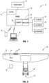
FIG. 1 , a video recording system for a vehicle is shown generally at 10.Video recording system 10 comprises aprocessor 20, and at least a first camera orother imager 24 capable of being in communication withprocessor 20.Processor 20 is disposed in arearview mirror assembly 28 of the vehicle.Rearview mirror assembly 28 further comprises ahousing 32, as shown inFIG. 2 . A printed circuit board (PCB) 36 is disposed withinhousing 32, andprocessor 20 is disposed onPCB 36. - In some embodiments,
housing 32 supports amirror element 40.Mirror element 40 may be configured to allow a driver of a vehicle to see objects or scenes behind the vehicle whenrearview mirror assembly 28 is mounted on a windshield of a vehicle. In some embodiments,rearview mirror assembly 28 may further comprise an electro-optic element 48.Mirror element 40 may be disposed between electro-optic element 48 and asupport plate 44.Support plate 44 may be disposed betweenmirror element 40 andPCB 36. In some embodiments, mirror element may comprise a display element such as a liquid crystal display. - First camera or
imager 24 may be disposed within or secured to an interior or exterior surface of the vehicle.First imager 24 may be disposed in a location remote fromrearview mirror assembly 28. In some embodiments,first imager 24 may be disposed at the top of the vehicle windshield, adjacent to or within a headliner of a vehicle ceiling, or on a ceiling console. In some embodiments,first imager 24 may be disposed withinrearview mirror assembly 28.Housing 32 ofrearview mirror assembly 28 may define an imager opening (not shown).First imager 24 may be configured to capture an image of a scene to the exterior ofhousing 32 through imager opening. First imager 24 may be disposed so as to be capable of capturing images of an area in front offirst imager 24.First imager 24 is capable of capturing video images.First imager 24 may have a wide-angle lens having a wide field of view.First imager 24 is in electrical communication withprocessor 20. Data from images captured byfirst imager 24 may be sent directly toprocessor 20 for processing.- Referring now to
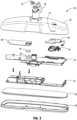
FIGS. 3 and4 ,housing 32 defines anopening 52 configured to allow a removablemedia storage card 56 to be inserted intorearview mirror assembly 28. When in place,media storage card 56 may be placed in selective communication withprocessor 20.Media storage card 56 may comprise non-volatile storage, and may comprise one of a secure digital card (SD card), a mini SD card, a microSD card, multimedia storage cards, and the like. Whenmedia storage card 56 is inserted into opening 52 of housing and is in communication withprocessor 20, data from images captured byfirst imager 24 may be capable of being stored onmedia storage card 56. - In some embodiments,
processor 20 ofrearview mirror assembly 28 additionally or alternatively comprises amemory 62.Memory 62 is disposed onPCB 36.Memory 62 may be random access memory, read only memory, flash memory, hard disk storage, flash memory storage, solid state drive memory, and the like.Memory 62 may be non-removable from rearview mirror assembly. Data from captured images may be stored inmemory 62. The data may be accessible or downloadable by a wired or wireless connection betweenvideo recording system 10 and a remote device, such as a user's mobile telephone, a laptop, or a tablet computer. In some embodiments, the data may be accessed, viewed, and/or downloaded via a wireless connection such as Bluetooth®, Wi-Fi, or radio frequency communication. In some embodiments, to access, view, or download the data frommemory 62, a user may connect a wired connector to a dedicated port (not shown) defined inhousing 32 ofrearview mirror assembly 28. The dedicated port may be configured to accept the wired connection to enable a user to access, view, or download data from captured images. In some embodiments, images may be transmitted directly to a user's account, and the user may view the images contemporaneously. For example, a parent may be able to monitor a child's driving by viewing images from a remote device such as a mobile telephone, computer, or smart television as they are generated. - In some embodiments,
PCB 36 may be configured to holdmedia storage card 56 whenmedia storage card 56 is inserted intorearview mirror assembly 28. In some embodiments, asecondary PCB 60 may be configured to holdmedia storage card 56.Secondary PCB 60 may be configured to be in communication withPCB 36. In some embodiments,secondary PCB 60 may be directly connected toPCB 36. In some embodiments,secondary PCB 60 may be connected toPCB 36 via a cable, harness or other wiring (not shown). Data from images captured byfirst imager 24 may be transmitted fromimager 24 toprocessor 20 for processing. After data from the images has been processed byprocessor 20, the data may be transmitted tomedia storage card 56 ormemory 62 for storage. Media storage card 56 may be capable of being removed fromrearview mirror assembly 28 by a user, thereby allowing the user to view captured and stored images. Images may be viewed on a device that is compatible withmedia storage card 56 and is capable of displaying images. Data on images frommedia storage card 56 may be downloaded to and saved on remote devices such as mobile telephones, laptop computers, or tablet computers. Similarly, a user may view, transmit, and/or download images stored onmemory 62. Images may be downloaded or transmitted to or viewed onrearview mirror assembly 28, or a remote device such as a mobile telephone, a computer, or a smart television.Video recording system 10 may be configured to be activated upon the vehicle being turned on or the ignition of the vehicle being started. In some embodiments, oncevideo recording system 10 has been activated,first imager 24 may begin capturing images. In some embodiments,first imager 24 may begin capturing images once a particular event has occurred. The particular event may be, for example, putting the vehicle into a forward gear or interacting with auser interface 76 ofvideo recording system 10.- Power may be supplied to
video recording system 10 by apower supply 72 associated with the vehicle. In some embodiments,vehicle recording system 10 may be configured to turn off after the vehicle ignition and/or power to the vehicle accessories is turned off. In some embodiments,video recording system 10 may continue to operate until the occurrence of a particular event or for a predetermined period of time after the vehicle ignition and/or power to vehicle accessories is turned off. - In some embodiments,
rearview mirror assembly 28 may further comprise abattery 74.Battery 74 may be configured to provide power tovideo recording system 10 upon power from thevehicle 10 being turned off.Battery 74 may be capable of providing sufficient power to allowvideo recording system 10 to save any images captured and not stored prior to the receipt, byvideo recording system 10, of an indication to turn off. - In some embodiments,
rearview mirror assembly 28 may comprise a capacitor, supercapacitor, solar cell, or other energy storage device (not shown) to provide power to the system, especially after the vehicle power supply has been disrupted or stopped. In some embodiments, other energy storage devices may be configured to provide the power necessary to save data related to images that have not yet been saved in the event that power tovideo recording system 10 is turned off prior to all recently-captured images being saved. The saved images may be saved inmemory 62 or onmedia storage card 56. The saved images may additionally or alternatively be transmitted to cloud storage or may be displayed onrearview mirror assembly 28 or on an external device such as a smart phone or computer. Once stored, the saved images may be transmitted to an external device or displayed at a user's convenience. Video recording system 10 may further comprise auser interface 76.User interface 76 may be disposed onrearview mirror assembly 28 or may be located remotely fromrearview mirror assembly 28. For example, in some embodiments,user interface 76 may comprise a plurality of buttons mounted onhousing 32 or elsewhere onrearview mirror assembly 28. In some embodiments, user interface additionally or alternatively may be accessed through a program accessible through aremote device 78 such as a user's mobile telephone, laptop computer, or tablet computer.User interface 76 may be configured to allow users to save particular images or images captured during a particular time period. For example,user interface 76 may, upon receipt of an appropriate user input, cause recently-recorded images to be placed in a saved status inmedia storage card 56 ormemory 62. The saved images may include images recorded over a certain time interval, such as images recorded in the two minutes just prior to the receipt of the user input.- In some embodiments,
user interface 76 may allow a user, upon receipt of an appropriate user input, to display images. In some embodiments,rearview mirror assembly 28 comprises adisplay element 80.Display element 80 may be capable of selectively displaying digital images. In some embodiments,display element 80 may comprise a liquid crystal display. Upon receipt of an appropriate user input, captured images may be displayed on at least aportion 82 ofdisplay element 80 ofrearview mirror assembly 28, as shown inFIG. 5B . In some embodiments, a menu for controlling video playback and the like may be selectively displayed on at least a portion ofdisplay element 80. - In some embodiments,
video recording system 10 may be capable of transmitting captured images and audio to another device such as a user's mobile telephone, laptop, or tablet computer. The transmission of the captured images may be done wirelessly or via a wired connection.Video recording system 10 may utilize Bluetooth®, Wi-Fi, radio frequency communication or combinations thereof. Upon receipt of a user input, images captured byvideo recording system 10 may be displayed on a user's mobile telephone or computer. The transmitted images may also be downloaded to and saved on a remote device such as a user's mobile telephone or computer. - In some embodiments,
video recording system 10 may further comprise at least oneindicator 84 as shown inFIG. 5A . The at least oneindicator 84 may comprise, for example, a light source such as a light emitting diode (LED). The at least oneindicator 84 may be capable of selectively illuminating and of being seen throughmirror element 40 ofrearview mirror assembly 28. The at least oneindicator 84 may be configured to indicate to the user a status ofvideo recording system 10, such as thatvideo recording system 10 is actively recording or that a save request was successful. - In some embodiments, opening 52 in
housing 32 is disposed on or toward one side ofrearview mirror assembly 28, andprocessor 20 is disposed on the opposite side. For example, opening 52 may be disposed toward the right side ofhousing 32 andprocessor 20 may be disposed withinhousing 32 toward the left side ofrearview mirror assembly 28. This arrangement, with the heat-generatingprocessor 20 disposed at a distance from the location ofmedia storage card 56, may reduce the amount of heat thatmedia storage card 56 is exposed to. Similarly,memory 62 may be disposed on the opposite side ofhousing 32 fromprocessor 20, thereby reducing the amount of heat thatmemory 62 is exposed to. - In some embodiments, a
heat sink 88 may be disposed withinhousing 32 proximate toprocessor 20. Aspacer 92 of thermally conductive material may connectprocessor 20 toheat sink 88.Spacer 92 may comprise silicon or other conductive material, and may be capable of conducting heat generated byprocessor 20 toheat sink 88 for dissipation. - In some embodiments, a
PCB holder 94 may be disposed withinhousing 32 and be configured to holdsecondary PCB 60.PCB holder 94 may be of a plastic or other low- or non-thermally-transmitting material.PCB holder 94 may act to provide a layer of insulation betweenmedia storage card 56 andPCB 36, thereby reducing the amount of heat thatmedia storage card 56 is exposed to. In some embodiments,secondary PCB 60 may be disposed directly onPCB 36. - In some embodiments,
video recording system 10 may further comprise a microphone or otheraudio input device 96.Microphone 96 may be in communication withprocessor 20 and withmedia storage card 56.Microphone 96 may be configured to capture audio from within the cabin of the vehicle or from the exterior of the vehicle.Microphone 96 may be configured to transmit the captured audio tomedia storage device 56 ormemory 62 for storage. The captured audio may be linked with stored video. - In some embodiments,
video recording system 10 may be in communication with the accident detection system(s) of the vehicle. The accident detection systems may include, for example, accelerometers or devices that determine whether airbags have been deployed. Upon receipt of an input indicating that an accident has occurred,video recording system 10 may be configured to causeprocessor 20 to save recently captured images. The saved images may be from a predetermined amount of time prior to the receipt of the indication of the accident, and may extend at least through the time at whichvideo recording system 10 received the indication of the accident. This may give users an opportunity to access images of the events that preceded the accident. - In some embodiments, an accident-detection sensor (not shown) may be disposed within
rearview mirror assembly 28. The accident-detection sensor may comprise, for example, an accelerometer.Video recording system 10 may be in communication with the accident-detection sensor. Upon receipt of an input from the accident-detection sensor that an accident may have occurred,video recording system 10 may be configured to causeprocessor 20 to save recently captured images covering a predetermined period of time, thereby providing users with images of events leading up to the incident that triggered the accident-detection sensor to indicate that an accident occurred. - In some embodiments,
video recording system 10 may comprise at least a second camera orimager 64.Second imager 64 may be disposed within or secured to the vehicle.Second imager 64 may be disposed so as to have a field of view that enables it to capture images from the rear of the vehicle.Second imager 64 may have a wide-angle field of view.Second imager 64 may be in electrical communication withprocessor 20. Images captured bysecond imager 64 may be transmitted toprocessor 20 for processing, and data from images may then be transmitted tomedia storage card 56 ormemory 62 for storage. More than two imagers may be used to capture images exterior to the vehicle and still remain within the scope of this disclosure. This may include imagers disposed to capture images to the side(s) of the vehicle, imagers to capture images at angles from the vehicle, and imagers to capture images above the vehicle. Rearview mirror assembly 28 may be mounted to a windshield or ceiling of the vehicle by a mountingelement 68. Mountingelement 68 may define achannel 70 through which wires (not shown) may extend. The wires may connect at least oneimager processor 20, transmitting data from images captured by the at least oneimager processor 20.Media storage card 56 may be configured to hold a certain amount of data. For example,media storage card 56 may be configured to hold data covering ninety minutes of images. If a determination is made thatmedia storage card 56 does not have sufficient remaining storage to store additional images, data will be stored over existing images, thereby erasing the previously-stored images. In general, the erased images will be the oldest stored images. However, images that are in a saved status will not be erased until the occurrence of a predetermined event, such as the receipt of a particular user input or the passage of a predetermined amount of time.- The
rearview mirror assembly 28 of this disclosure may include an electro-optic rearview assembly.Rearview mirror assembly 28 may alternatively include a prismatic mirror.Rearview mirror assembly 28 may additionally or alternatively include an electronic display that displays an image as sensed by a rearward facing camera or other imaging system (see, for example, commonly assignedU.S. Pat. No. 6,550,949 entitled "SYSTEMS AND COMPONENTS FOR ENHANCING REAR VISION FROM A VEHICLE," filed on Sep. 15, 1998, by Frederick T. Bauer et al .). Additionally or alternatively,rearview mirror assembly 28 may include both an electro-optic rearview assembly and a display device for providing an image from a rearward facing camera or other imaging system. - A method for capturing and storing images, including video images, exterior to a vehicle may include activating
video recording system 10 upon the turning on of the vehicle. Oncevideo recording system 10 has been activated, at least oneimager processor 20 disposed within arearview mirror assembly 28 of the vehicle.Processor 20 may be configured to process the data from the captured images. Video recording system 10 further comprises amemory Memory permanent memory 62 orremovable memory 56.Processor 20 may be configured to determine whether there is sufficient storage inmemory processor 20 may direct the data from the newly-captured images be written over the data from the oldest images inmemory Processor 20 then transmits the data tomemory - In some embodiments, images may be put into a saved status upon the receipt from the vehicle's accident-detection system of an indication that an accident may have occurred. In some embodiments,
video recording system 10 may comprise an accident-detection sensor, and images may be put into a saved status upon the receipt from the video recording system's accident-detection sensor of an indication that an accident may have occurred. Upon receipt of an indication that an accident may have occurred,video recording system 10 may cause the saving of images captured for a predetermined interval prior to the receipt of the indication that an accident may have occurred by putting the images in a saved status. - In some embodiments, a user may indicate through
user interface 76 that the user desires images be saved. For example,video recording system 10 may receive, throughuser interface 76, an input indicating that images should be saved. Upon receipt of the indication,processor 20 may place images captured within a predetermined period of time, such as the ninety seconds prior to the receipt of the input, into a saved status. - Images in a saved status may remain in the saved status until the receipt of a user input indicating that the particular saved images no longer need to be in a saved status and may be over-written with new images. This may be done by a user after viewing the image in the saved status. In some embodiments, images in a saved status may be removed from a saved status after the occurrence of a predetermined event. The predetermined event may include the passage of a predetermined period of time, such as one year.
- In this document, relational terms, such as first and second, top and bottom, front and back, left and right, vertical, horizontal, and the like, are used solely to distinguish one entity or action from another entity or action, without necessarily requiring or implying any actual such relationship, order, or number of such entities or actions. These terms are not meant to limit the element which they describe, as the various elements may be oriented differently in various applications. Furthermore, it is to be understood that the device may assume various orientations and step sequences, except where expressly specified to the contrary. It is also to be understood that the specific devices and processes illustrated in the attached drawings and described in the following specification are simply exemplary embodiments of the inventive concepts defined in the appended claims. Hence, specific dimensions and other physical characteristics relating to the embodiments disclosed herein are not to be considered as limiting, unless the claims expressly state otherwise.
- As used herein, the term "and/or," when used in a list of two or more items, means that any one of the listed items can be employed by itself, or any combination of two or more of the listed items can be employed. For example, if a composition is described as containing components A, B, and/or C, the composition can contain A alone; B alone; C alone; A and B in combination; A and C in combination; B and C in combination; or A, B, and C in combination.
Claims (14)
- A rearview mirror assembly (28) for a vehicle comprising:a housing (32);a display element (80);a mirror element (40) supported by the housing (32); anda processor (20) disposed on a printed circuit board (36) and at least partially enclosed within the housing (32);wherein the processor (20) is configured to be in communication with and to receive inputs from at least one imager (24, 64);wherein at least a portion of the display element is configured to selectively display images captured by the at least one imager (24, 64);wherein the at least one imager (24, 64) is disposed in a vehicle;wherein at least one imager (24, 64) is configured to capture images from the exterior of the vehicle;wherein the rearview mirror assembly (28) further comprises a memory (62) disposed on the printed circuit board (36) and configured to be in communication with the processor (20);wherein the housing (32) defines an opening (52) at a distance from the processor (20);wherein the opening (52) is configured to accept a removable media storage card capable of storing data from the captured images;wherein the opening (52) defined by the housing (32) is disposed toward a first side of the housing (32);wherein the processor (20) is disposed within the housing (32) toward a second side of the housing (32);wherein the processor (20) is disposed on a first end of the printed circuit board (36); andwherein the memory (62) is disposed on a second end of the circuit board in a spaced-apart relationship with the processor (20).
- The rearview mirror assembly (28) of claim 1, wherein the processor (20) is configured to be in communication with and is configured to receive inputs from at least two imagers (24, 64);wherein the captured images comprise video images; andwherein at least one imager (24, 64) is configured to capture images to the front of the vehicle and to transmit image data from the captured images to the processor (20).
- The rearview mirror assembly (28) of claim 2, wherein a first imager (24) is disposed in the vehicle and is configured to capture images of scenes to the front of the vehicle and a second imager (64) is configured to capture images to the rear of the vehicle; and
wherein the first and the second imagers (24, 64) are configured to transmit data on the captured images to the processor (20). - The rearview mirror assembly (28) of one of claims 1-3, wherein the rearview mirror assembly (28) is configured to receive power from a vehicle power supply (72); andwherein the processor (20) and the at least one imager (24, 64) are configured to be activated upon the vehicle ignition being turned on, and wherein the processor (20) and the at least one imager (24, 64) are configured to be turned off upon one of the vehicle ignition being turned off and power to the vehicle accessories being turned off;the rearview mirror assembly (28) further comprising a back-up battery (74);wherein the back-up battery (74) is capable of providing sufficient power to allow the processor (20) to cause any images not saved before power to the video recording system (10) is turned off to be saved.
- The rearview mirror assembly (28) of one of claims 1-4, further comprising a user interface (76) capable of, upon receipt of a user input, causing the saving of images captured within a predetermined time interval prior to the receipt of the user input.
- A video recording system (10) for a vehicle, comprising:the rearview mirror assembly (28) of claim 1; anda first imager (24) in communication with the processor (20) and capable of capturing video images;wherein the rearview mirror assembly (28) further comprises a user interface (76);wherein the printed circuit board (36) is disposed within the rearview mirror assembly (28);wherein the processor (20) is configured to process data from the captured images; andwherein the user interface (76) is capable of allowing a user to selectively save video captured by the imager (24).
- The video recording system (10) of claim 6, wherein the first imager (24) is disposed in a vehicle on one of a headliner of the vehicle and a windshield of the vehicle;wherein the first imager (24) is configured to capture images of scenes to the front of the vehicle and to transmit data on the captured images to the processor (20); andwherein the captured images comprise video images.
- The video recording system (10) of claim 6 or 7, further comprising a second imager (64) in communication with the processor (20);
wherein the second imager (64) is disposed in a vehicle and is configured to capture images to the rear of the vehicle and to transmit data on the captured images to the processor (20). - The video recording system (10) of one of claims 6 to 8, wherein the video recording system (10) is configured to receive power from a vehicle power supply (72);wherein the video recording system (10) is configured to be activated upon the vehicle ignition being turned on andwherein the video recording system (10) is configured to be turned off upon one of the vehicle ignition being turned off and power to the vehicle accessories being turned off.
- The video recording system (10) of one of claims 6 to 9, further comprising a back-up battery (74); wherein the back-up battery (74) is capable of providing sufficient power to allow the video recording system (10) to save any images captured after a power supply to the video recording system (10) is turned off.
- The video recording system (10) of one of claims 6 to 10, wherein the user interface (76) is capable of, upon receipt of a user input, saving images captured within a predetermined time interval prior to the receipt of the user input.
- The video recording system (10) of one of claims 6 to 11, wherein the rearview mirror assembly (28) comprises a display element (80), and wherein at least a portion of the display element (80) is configured to selectively display images captured by the first imager (24).
- The video recording system (10) of one of claims 6 to 12, further comprising at least one indicator (84) disposed so as to be selectively visible through the mirror element (40);
wherein the indicator (84) is configured to indicate a status of the video recording system (10). - The video recording system (10) of one of claims 6 to 13, wherein the video recording system (10) is capable of transmitting captured images wirelessly to another device.
Applications Claiming Priority (2)
| Application Number | Priority Date | Filing Date | Title |
|---|---|---|---|
| US201962907040P | 2019-09-27 | 2019-09-27 | |
| PCT/US2020/052677WO2021062125A1 (en) | 2019-09-27 | 2020-09-25 | Video recording mirror |
Publications (3)
| Publication Number | Publication Date |
|---|---|
| EP4034424A1 EP4034424A1 (en) | 2022-08-03 |
| EP4034424A4 EP4034424A4 (en) | 2022-11-30 |
| EP4034424B1true EP4034424B1 (en) | 2023-08-30 |
Family
ID=75162616
Family Applications (1)
| Application Number | Title | Priority Date | Filing Date |
|---|---|---|---|
| EP20867900.1AActiveEP4034424B1 (en) | 2019-09-27 | 2020-09-25 | Video recording mirror |
Country Status (6)
| Country | Link |
|---|---|
| US (1) | US20210099663A1 (en) |
| EP (1) | EP4034424B1 (en) |
| JP (1) | JP7534394B2 (en) |
| KR (1) | KR102752015B1 (en) |
| CN (1) | CN114502429A (en) |
| WO (1) | WO2021062125A1 (en) |
Families Citing this family (2)
| Publication number | Priority date | Publication date | Assignee | Title |
|---|---|---|---|---|
| KR102819190B1 (en)* | 2020-05-13 | 2025-06-10 | 현대모비스 주식회사 | Room mirror removal monitoring device with electronic toll collection |
| WO2023014966A1 (en)* | 2021-08-06 | 2023-02-09 | Gentex Corporation | Heat mitigation for rearview assembly |
Family Cites Families (17)
| Publication number | Priority date | Publication date | Assignee | Title |
|---|---|---|---|---|
| US6550949B1 (en) | 1996-06-13 | 2003-04-22 | Gentex Corporation | Systems and components for enhancing rear vision from a vehicle |
| WO2002095757A2 (en)* | 2001-05-23 | 2002-11-28 | Trevor Keith Byford | Vehicle incident recorder |
| GB2434690A (en)* | 2006-01-26 | 2007-08-01 | Shih-Hsiung Li | Sound recording device for use in vehicles |
| US20100123779A1 (en)* | 2008-11-18 | 2010-05-20 | Dennis Michael Snyder | Video recording system for a vehicle |
| US8237909B2 (en)* | 2009-02-06 | 2012-08-07 | Gentex Corporation | Vehicular rearview mirror assembly including integrated backlighting for a liquid crystal display (LCD) |
| US20100238289A1 (en)* | 2009-03-23 | 2010-09-23 | Chih-Hsien Wu | In-car audio/video recording rearview mirror assembly |
| KR101270401B1 (en)* | 2010-12-31 | 2013-06-07 | 강문수 | Room mirror having video recording fuction |
| JP6303191B2 (en) | 2013-05-22 | 2018-04-04 | 株式会社ユピテル | Electronic equipment and drive recorder |
| RU150950U1 (en)* | 2014-06-10 | 2015-03-10 | Вадим Евгеньевич Бондаренко | MULTIFUNCTION REAR VIEW MIRROR |
| JP6518907B2 (en)* | 2014-09-09 | 2019-05-29 | 株式会社ユピテル | Vehicle equipment |
| US10819943B2 (en)* | 2015-05-07 | 2020-10-27 | Magna Electronics Inc. | Vehicle vision system with incident recording function |
| WO2018195671A1 (en)* | 2017-04-28 | 2018-11-01 | Klashwerks Inc. | In-vehicle monitoring system and devices |
| JP6822303B2 (en)* | 2017-04-28 | 2021-01-27 | トヨタ自動車株式会社 | Image display device |
| JP7122729B2 (en)* | 2017-05-19 | 2022-08-22 | 株式会社ユピテル | Drive recorder, display device and program for drive recorder |
| CN109866687A (en)* | 2017-12-03 | 2019-06-11 | 张轶皓 | A kind of rearview mirror automobile data recorder that can automatically adjust rain brush |
| JP7188727B2 (en)* | 2018-02-20 | 2022-12-13 | 株式会社東海理化電機製作所 | Visual recognition device for vehicles |
| JP6643585B2 (en)* | 2018-08-22 | 2020-02-12 | 株式会社ユピテル | Vehicle rearview mirror |
- 2020
- 2020-09-25WOPCT/US2020/052677patent/WO2021062125A1/ennot_activeCeased
- 2020-09-25CNCN202080067213.XApatent/CN114502429A/enactivePending
- 2020-09-25USUS17/032,476patent/US20210099663A1/ennot_activeAbandoned
- 2020-09-25EPEP20867900.1Apatent/EP4034424B1/enactiveActive
- 2020-09-25KRKR1020227010473Apatent/KR102752015B1/enactiveActive
- 2020-09-25JPJP2022519517Apatent/JP7534394B2/enactiveActive
Also Published As
| Publication number | Publication date |
|---|---|
| KR20220072831A (en) | 2022-06-02 |
| EP4034424A4 (en) | 2022-11-30 |
| EP4034424A1 (en) | 2022-08-03 |
| CN114502429A (en) | 2022-05-13 |
| JP2023501876A (en) | 2023-01-20 |
| US20210099663A1 (en) | 2021-04-01 |
| JP7534394B2 (en) | 2024-08-14 |
| WO2021062125A1 (en) | 2021-04-01 |
| KR102752015B1 (en) | 2025-01-08 |
Similar Documents
| Publication | Publication Date | Title |
|---|---|---|
| AU2006292532C1 (en) | Rear view mirror with integrated video system | |
| US20100123779A1 (en) | Video recording system for a vehicle | |
| US20160381292A1 (en) | Dash cam | |
| JP3182941U (en) | In-vehicle video recording device | |
| JP3140339U (en) | Traveling image recording rearview mirror | |
| EP4034424B1 (en) | Video recording mirror | |
| JP2013256167A (en) | Drive recorder system and in-vehicle camera system | |
| JP2014044692A (en) | Drive recorder system | |
| JP2023181327A (en) | Automotive driving recorder | |
| CN105034951A (en) | A smart rearview mirror | |
| CN103568968A (en) | Rear-view mirror driving recorder with reminding function | |
| JP2021034975A (en) | Recording control device, recording control method, and program | |
| CN201400133Y (en) | Rear-view mirror with hidden video recorder | |
| JP7501144B2 (en) | Vehicle recording device and recording control method | |
| KR20040019427A (en) | System and Method for Sensing Car | |
| CN211787233U (en) | Multifunctional automobile data recorder | |
| KR101801375B1 (en) | Electronic device for vehicle, multifunction control device and operating method of electronic device for vehicle | |
| JP7730232B2 (en) | Video recording device and video recording program | |
| CN216352482U (en) | A video noise reduction vehicle monitor based on extremely low light conditions | |
| JP7526992B2 (en) | Devices and programs | |
| CN204750086U (en) | A kind of multifunctional car anti-theft device and multifunctional car rearview mirror | |
| JP7657442B2 (en) | Power supply, recorder, programs, etc. | |
| JP7208493B2 (en) | Recording control device, recording control system, recording control method, and program | |
| TWM515981U (en) | Vehicle rearview mirror device with multi-view display and anti-theft positioning alarm function | |
| KR20160054909A (en) | A vehicle video recording device using the obd |
Legal Events
| Date | Code | Title | Description |
|---|---|---|---|
| STAA | Information on the status of an ep patent application or granted ep patent | Free format text:STATUS: THE INTERNATIONAL PUBLICATION HAS BEEN MADE | |
| PUAI | Public reference made under article 153(3) epc to a published international application that has entered the european phase | Free format text:ORIGINAL CODE: 0009012 | |
| STAA | Information on the status of an ep patent application or granted ep patent | Free format text:STATUS: REQUEST FOR EXAMINATION WAS MADE | |
| 17P | Request for examination filed | Effective date:20220222 | |
| AK | Designated contracting states | Kind code of ref document:A1 Designated state(s):AL AT BE BG CH CY CZ DE DK EE ES FI FR GB GR HR HU IE IS IT LI LT LU LV MC MK MT NL NO PL PT RO RS SE SI SK SM TR | |
| A4 | Supplementary search report drawn up and despatched | Effective date:20221031 | |
| RIC1 | Information provided on ipc code assigned before grant | Ipc:G07C 5/00 20060101ALI20221025BHEP Ipc:H04N 7/18 20060101ALI20221025BHEP Ipc:H04N 5/225 20060101ALI20221025BHEP Ipc:B60R 1/12 20060101AFI20221025BHEP | |
| DAV | Request for validation of the european patent (deleted) | ||
| DAX | Request for extension of the european patent (deleted) | ||
| REG | Reference to a national code | Ref country code:DE Free format text:PREVIOUS MAIN CLASS: B60R0001120000 Ipc:H04N0005222000 Ref country code:DE Ref legal event code:R079 Ref document number:602020016959 Country of ref document:DE Free format text:PREVIOUS MAIN CLASS: B60R0001120000 Ipc:H04N0005222000 | |
| GRAP | Despatch of communication of intention to grant a patent | Free format text:ORIGINAL CODE: EPIDOSNIGR1 | |
| STAA | Information on the status of an ep patent application or granted ep patent | Free format text:STATUS: GRANT OF PATENT IS INTENDED | |
| RIC1 | Information provided on ipc code assigned before grant | Ipc:H04N 5/222 20060101AFI20230404BHEP | |
| INTG | Intention to grant announced | Effective date:20230509 | |
| P01 | Opt-out of the competence of the unified patent court (upc) registered | Effective date:20230503 | |
| GRAS | Grant fee paid | Free format text:ORIGINAL CODE: EPIDOSNIGR3 | |
| GRAA | (expected) grant | Free format text:ORIGINAL CODE: 0009210 | |
| STAA | Information on the status of an ep patent application or granted ep patent | Free format text:STATUS: THE PATENT HAS BEEN GRANTED | |
| AK | Designated contracting states | Kind code of ref document:B1 Designated state(s):AL AT BE BG CH CY CZ DE DK EE ES FI FR GB GR HR HU IE IS IT LI LT LU LV MC MK MT NL NO PL PT RO RS SE SI SK SM TR | |
| REG | Reference to a national code | Ref country code:GB Ref legal event code:FG4D | |
| REG | Reference to a national code | Ref country code:CH Ref legal event code:EP | |
| REG | Reference to a national code | Ref country code:DE Ref legal event code:R096 Ref document number:602020016959 Country of ref document:DE | |
| REG | Reference to a national code | Ref country code:IE Ref legal event code:FG4D | |
| REG | Reference to a national code | Ref country code:LT Ref legal event code:MG9D | |
| REG | Reference to a national code | Ref country code:NL Ref legal event code:MP Effective date:20230830 | |
| REG | Reference to a national code | Ref country code:AT Ref legal event code:MK05 Ref document number:1606933 Country of ref document:AT Kind code of ref document:T Effective date:20230830 | |
| PG25 | Lapsed in a contracting state [announced via postgrant information from national office to epo] | Ref country code:GR Free format text:LAPSE BECAUSE OF FAILURE TO SUBMIT A TRANSLATION OF THE DESCRIPTION OR TO PAY THE FEE WITHIN THE PRESCRIBED TIME-LIMIT Effective date:20231201 | |
| PG25 | Lapsed in a contracting state [announced via postgrant information from national office to epo] | Ref country code:IS Free format text:LAPSE BECAUSE OF FAILURE TO SUBMIT A TRANSLATION OF THE DESCRIPTION OR TO PAY THE FEE WITHIN THE PRESCRIBED TIME-LIMIT Effective date:20231230 | |
| PG25 | Lapsed in a contracting state [announced via postgrant information from national office to epo] | Ref country code:SE Free format text:LAPSE BECAUSE OF FAILURE TO SUBMIT A TRANSLATION OF THE DESCRIPTION OR TO PAY THE FEE WITHIN THE PRESCRIBED TIME-LIMIT Effective date:20230830 Ref country code:RS Free format text:LAPSE BECAUSE OF FAILURE TO SUBMIT A TRANSLATION OF THE DESCRIPTION OR TO PAY THE FEE WITHIN THE PRESCRIBED TIME-LIMIT Effective date:20230830 Ref country code:NO Free format text:LAPSE BECAUSE OF FAILURE TO SUBMIT A TRANSLATION OF THE DESCRIPTION OR TO PAY THE FEE WITHIN THE PRESCRIBED TIME-LIMIT Effective date:20231130 Ref country code:LV Free format text:LAPSE BECAUSE OF FAILURE TO SUBMIT A TRANSLATION OF THE DESCRIPTION OR TO PAY THE FEE WITHIN THE PRESCRIBED TIME-LIMIT Effective date:20230830 Ref country code:LT Free format text:LAPSE BECAUSE OF FAILURE TO SUBMIT A TRANSLATION OF THE DESCRIPTION OR TO PAY THE FEE WITHIN THE PRESCRIBED TIME-LIMIT Effective date:20230830 Ref country code:IS Free format text:LAPSE BECAUSE OF FAILURE TO SUBMIT A TRANSLATION OF THE DESCRIPTION OR TO PAY THE FEE WITHIN THE PRESCRIBED TIME-LIMIT Effective date:20231230 Ref country code:HR Free format text:LAPSE BECAUSE OF FAILURE TO SUBMIT A TRANSLATION OF THE DESCRIPTION OR TO PAY THE FEE WITHIN THE PRESCRIBED TIME-LIMIT Effective date:20230830 Ref country code:GR Free format text:LAPSE BECAUSE OF FAILURE TO SUBMIT A TRANSLATION OF THE DESCRIPTION OR TO PAY THE FEE WITHIN THE PRESCRIBED TIME-LIMIT Effective date:20231201 Ref country code:FI Free format text:LAPSE BECAUSE OF FAILURE TO SUBMIT A TRANSLATION OF THE DESCRIPTION OR TO PAY THE FEE WITHIN THE PRESCRIBED TIME-LIMIT Effective date:20230830 Ref country code:AT Free format text:LAPSE BECAUSE OF FAILURE TO SUBMIT A TRANSLATION OF THE DESCRIPTION OR TO PAY THE FEE WITHIN THE PRESCRIBED TIME-LIMIT Effective date:20230830 | |
| PG25 | Lapsed in a contracting state [announced via postgrant information from national office to epo] | Ref country code:PL Free format text:LAPSE BECAUSE OF FAILURE TO SUBMIT A TRANSLATION OF THE DESCRIPTION OR TO PAY THE FEE WITHIN THE PRESCRIBED TIME-LIMIT Effective date:20230830 Ref country code:NL Free format text:LAPSE BECAUSE OF FAILURE TO SUBMIT A TRANSLATION OF THE DESCRIPTION OR TO PAY THE FEE WITHIN THE PRESCRIBED TIME-LIMIT Effective date:20230830 | |
| PG25 | Lapsed in a contracting state [announced via postgrant information from national office to epo] | Ref country code:ES Free format text:LAPSE BECAUSE OF FAILURE TO SUBMIT A TRANSLATION OF THE DESCRIPTION OR TO PAY THE FEE WITHIN THE PRESCRIBED TIME-LIMIT Effective date:20230830 | |
| PG25 | Lapsed in a contracting state [announced via postgrant information from national office to epo] | Ref country code:SM Free format text:LAPSE BECAUSE OF FAILURE TO SUBMIT A TRANSLATION OF THE DESCRIPTION OR TO PAY THE FEE WITHIN THE PRESCRIBED TIME-LIMIT Effective date:20230830 Ref country code:RO Free format text:LAPSE BECAUSE OF FAILURE TO SUBMIT A TRANSLATION OF THE DESCRIPTION OR TO PAY THE FEE WITHIN THE PRESCRIBED TIME-LIMIT Effective date:20230830 Ref country code:ES Free format text:LAPSE BECAUSE OF FAILURE TO SUBMIT A TRANSLATION OF THE DESCRIPTION OR TO PAY THE FEE WITHIN THE PRESCRIBED TIME-LIMIT Effective date:20230830 Ref country code:EE Free format text:LAPSE BECAUSE OF FAILURE TO SUBMIT A TRANSLATION OF THE DESCRIPTION OR TO PAY THE FEE WITHIN THE PRESCRIBED TIME-LIMIT Effective date:20230830 Ref country code:DK Free format text:LAPSE BECAUSE OF FAILURE TO SUBMIT A TRANSLATION OF THE DESCRIPTION OR TO PAY THE FEE WITHIN THE PRESCRIBED TIME-LIMIT Effective date:20230830 Ref country code:CZ Free format text:LAPSE BECAUSE OF FAILURE TO SUBMIT A TRANSLATION OF THE DESCRIPTION OR TO PAY THE FEE WITHIN THE PRESCRIBED TIME-LIMIT Effective date:20230830 Ref country code:PT Free format text:LAPSE BECAUSE OF FAILURE TO SUBMIT A TRANSLATION OF THE DESCRIPTION OR TO PAY THE FEE WITHIN THE PRESCRIBED TIME-LIMIT Effective date:20240102 Ref country code:SK Free format text:LAPSE BECAUSE OF FAILURE TO SUBMIT A TRANSLATION OF THE DESCRIPTION OR TO PAY THE FEE WITHIN THE PRESCRIBED TIME-LIMIT Effective date:20230830 | |
| REG | Reference to a national code | Ref country code:CH Ref legal event code:PL | |
| PG25 | Lapsed in a contracting state [announced via postgrant information from national office to epo] | Ref country code:LU Free format text:LAPSE BECAUSE OF NON-PAYMENT OF DUE FEES Effective date:20230925 | |
| REG | Reference to a national code | Ref country code:BE Ref legal event code:MM Effective date:20230930 | |
| PG25 | Lapsed in a contracting state [announced via postgrant information from national office to epo] | Ref country code:LU Free format text:LAPSE BECAUSE OF NON-PAYMENT OF DUE FEES Effective date:20230925 Ref country code:IT Free format text:LAPSE BECAUSE OF FAILURE TO SUBMIT A TRANSLATION OF THE DESCRIPTION OR TO PAY THE FEE WITHIN THE PRESCRIBED TIME-LIMIT Effective date:20230830 Ref country code:MC Free format text:LAPSE BECAUSE OF FAILURE TO SUBMIT A TRANSLATION OF THE DESCRIPTION OR TO PAY THE FEE WITHIN THE PRESCRIBED TIME-LIMIT Effective date:20230830 | |
| REG | Reference to a national code | Ref country code:DE Ref legal event code:R097 Ref document number:602020016959 Country of ref document:DE | |
| REG | Reference to a national code | Ref country code:IE Ref legal event code:MM4A | |
| PG25 | Lapsed in a contracting state [announced via postgrant information from national office to epo] | Ref country code:IE Free format text:LAPSE BECAUSE OF NON-PAYMENT OF DUE FEES Effective date:20230925 | |
| PLBE | No opposition filed within time limit | Free format text:ORIGINAL CODE: 0009261 | |
| STAA | Information on the status of an ep patent application or granted ep patent | Free format text:STATUS: NO OPPOSITION FILED WITHIN TIME LIMIT | |
| PG25 | Lapsed in a contracting state [announced via postgrant information from national office to epo] | Ref country code:CH Free format text:LAPSE BECAUSE OF NON-PAYMENT OF DUE FEES Effective date:20230930 | |
| PG25 | Lapsed in a contracting state [announced via postgrant information from national office to epo] | Ref country code:IE Free format text:LAPSE BECAUSE OF NON-PAYMENT OF DUE FEES Effective date:20230925 Ref country code:CH Free format text:LAPSE BECAUSE OF NON-PAYMENT OF DUE FEES Effective date:20230930 Ref country code:SI Free format text:LAPSE BECAUSE OF FAILURE TO SUBMIT A TRANSLATION OF THE DESCRIPTION OR TO PAY THE FEE WITHIN THE PRESCRIBED TIME-LIMIT Effective date:20230830 | |
| 26N | No opposition filed | Effective date:20240603 | |
| PG25 | Lapsed in a contracting state [announced via postgrant information from national office to epo] | Ref country code:BE Free format text:LAPSE BECAUSE OF NON-PAYMENT OF DUE FEES Effective date:20230930 | |
| PGFP | Annual fee paid to national office [announced via postgrant information from national office to epo] | Ref country code:DE Payment date:20240820 Year of fee payment:5 | |
| PGFP | Annual fee paid to national office [announced via postgrant information from national office to epo] | Ref country code:GB Payment date:20240821 Year of fee payment:5 | |
| PGFP | Annual fee paid to national office [announced via postgrant information from national office to epo] | Ref country code:FR Payment date:20240820 Year of fee payment:5 | |
| PG25 | Lapsed in a contracting state [announced via postgrant information from national office to epo] | Ref country code:BG Free format text:LAPSE BECAUSE OF FAILURE TO SUBMIT A TRANSLATION OF THE DESCRIPTION OR TO PAY THE FEE WITHIN THE PRESCRIBED TIME-LIMIT Effective date:20230830 | |
| PG25 | Lapsed in a contracting state [announced via postgrant information from national office to epo] | Ref country code:BG Free format text:LAPSE BECAUSE OF FAILURE TO SUBMIT A TRANSLATION OF THE DESCRIPTION OR TO PAY THE FEE WITHIN THE PRESCRIBED TIME-LIMIT Effective date:20230830 | |
| PG25 | Lapsed in a contracting state [announced via postgrant information from national office to epo] | Ref country code:CY Free format text:LAPSE BECAUSE OF FAILURE TO SUBMIT A TRANSLATION OF THE DESCRIPTION OR TO PAY THE FEE WITHIN THE PRESCRIBED TIME-LIMIT; INVALID AB INITIO Effective date:20200925 | |
| PG25 | Lapsed in a contracting state [announced via postgrant information from national office to epo] | Ref country code:HU Free format text:LAPSE BECAUSE OF FAILURE TO SUBMIT A TRANSLATION OF THE DESCRIPTION OR TO PAY THE FEE WITHIN THE PRESCRIBED TIME-LIMIT; INVALID AB INITIO Effective date:20200925 |