EP4034397B1 - Thermal treatment system intended for a motor vehicle - Google Patents
Thermal treatment system intended for a motor vehicleDownload PDFInfo
- Publication number
- EP4034397B1 EP4034397B1EP20789653.1AEP20789653AEP4034397B1EP 4034397 B1EP4034397 B1EP 4034397B1EP 20789653 AEP20789653 AEP 20789653AEP 4034397 B1EP4034397 B1EP 4034397B1
- Authority
- EP
- European Patent Office
- Prior art keywords
- transfer fluid
- heat
- heat transfer
- heat exchanger
- fluid circuit
- Prior art date
- Legal status (The legal status is an assumption and is not a legal conclusion. Google has not performed a legal analysis and makes no representation as to the accuracy of the status listed.)
- Active
Links
Images


Classifications
- B—PERFORMING OPERATIONS; TRANSPORTING
- B60—VEHICLES IN GENERAL
- B60H—ARRANGEMENTS OF HEATING, COOLING, VENTILATING OR OTHER AIR-TREATING DEVICES SPECIALLY ADAPTED FOR PASSENGER OR GOODS SPACES OF VEHICLES
- B60H1/00—Heating, cooling or ventilating [HVAC] devices
- B60H1/00271—HVAC devices specially adapted for particular vehicle parts or components and being connected to the vehicle HVAC unit
- B60H1/00278—HVAC devices specially adapted for particular vehicle parts or components and being connected to the vehicle HVAC unit for the battery
- B—PERFORMING OPERATIONS; TRANSPORTING
- B60—VEHICLES IN GENERAL
- B60H—ARRANGEMENTS OF HEATING, COOLING, VENTILATING OR OTHER AIR-TREATING DEVICES SPECIALLY ADAPTED FOR PASSENGER OR GOODS SPACES OF VEHICLES
- B60H1/00—Heating, cooling or ventilating [HVAC] devices
- B60H1/00357—Air-conditioning arrangements specially adapted for particular vehicles
- B60H1/00385—Air-conditioning arrangements specially adapted for particular vehicles for vehicles having an electrical drive, e.g. hybrid or fuel cell
- B60H1/00392—Air-conditioning arrangements specially adapted for particular vehicles for vehicles having an electrical drive, e.g. hybrid or fuel cell for electric vehicles having only electric drive means
- B—PERFORMING OPERATIONS; TRANSPORTING
- B60—VEHICLES IN GENERAL
- B60H—ARRANGEMENTS OF HEATING, COOLING, VENTILATING OR OTHER AIR-TREATING DEVICES SPECIALLY ADAPTED FOR PASSENGER OR GOODS SPACES OF VEHICLES
- B60H1/00—Heating, cooling or ventilating [HVAC] devices
- B60H1/02—Heating, cooling or ventilating [HVAC] devices the heat being derived from the propulsion plant
- B60H1/14—Heating, cooling or ventilating [HVAC] devices the heat being derived from the propulsion plant otherwise than from cooling liquid of the plant, e.g. heat from the grease oil, the brakes, the transmission unit
- B60H1/143—Heating, cooling or ventilating [HVAC] devices the heat being derived from the propulsion plant otherwise than from cooling liquid of the plant, e.g. heat from the grease oil, the brakes, the transmission unit the heat being derived from cooling an electric component, e.g. electric motors, electric circuits, fuel cells or batteries
- B—PERFORMING OPERATIONS; TRANSPORTING
- B60—VEHICLES IN GENERAL
- B60H—ARRANGEMENTS OF HEATING, COOLING, VENTILATING OR OTHER AIR-TREATING DEVICES SPECIALLY ADAPTED FOR PASSENGER OR GOODS SPACES OF VEHICLES
- B60H1/00—Heating, cooling or ventilating [HVAC] devices
- B60H1/32—Cooling devices
- B60H1/3204—Cooling devices using compression
- B60H1/3205—Control means therefor
- B60H1/3211—Control means therefor for increasing the efficiency of a vehicle refrigeration cycle
- B—PERFORMING OPERATIONS; TRANSPORTING
- B60—VEHICLES IN GENERAL
- B60H—ARRANGEMENTS OF HEATING, COOLING, VENTILATING OR OTHER AIR-TREATING DEVICES SPECIALLY ADAPTED FOR PASSENGER OR GOODS SPACES OF VEHICLES
- B60H1/00—Heating, cooling or ventilating [HVAC] devices
- B60H1/32—Cooling devices
- B60H1/3204—Cooling devices using compression
- B60H1/3205—Control means therefor
- B60H1/3213—Control means therefor for increasing the efficiency in a vehicle heat pump
- B—PERFORMING OPERATIONS; TRANSPORTING
- B60—VEHICLES IN GENERAL
- B60H—ARRANGEMENTS OF HEATING, COOLING, VENTILATING OR OTHER AIR-TREATING DEVICES SPECIALLY ADAPTED FOR PASSENGER OR GOODS SPACES OF VEHICLES
- B60H1/00—Heating, cooling or ventilating [HVAC] devices
- B60H1/32—Cooling devices
- B60H1/3204—Cooling devices using compression
- B60H1/3228—Cooling devices using compression characterised by refrigerant circuit configurations
- B60H1/32284—Cooling devices using compression characterised by refrigerant circuit configurations comprising two or more secondary circuits, e.g. at evaporator and condenser side
- B—PERFORMING OPERATIONS; TRANSPORTING
- B60—VEHICLES IN GENERAL
- B60H—ARRANGEMENTS OF HEATING, COOLING, VENTILATING OR OTHER AIR-TREATING DEVICES SPECIALLY ADAPTED FOR PASSENGER OR GOODS SPACES OF VEHICLES
- B60H1/00—Heating, cooling or ventilating [HVAC] devices
- B60H1/32—Cooling devices
- B60H1/3204—Cooling devices using compression
- B60H1/323—Cooling devices using compression characterised by comprising auxiliary or multiple systems, e.g. plurality of evaporators, or by involving auxiliary cooling devices
- B—PERFORMING OPERATIONS; TRANSPORTING
- B60—VEHICLES IN GENERAL
- B60L—PROPULSION OF ELECTRICALLY-PROPELLED VEHICLES; SUPPLYING ELECTRIC POWER FOR AUXILIARY EQUIPMENT OF ELECTRICALLY-PROPELLED VEHICLES; ELECTRODYNAMIC BRAKE SYSTEMS FOR VEHICLES IN GENERAL; MAGNETIC SUSPENSION OR LEVITATION FOR VEHICLES; MONITORING OPERATING VARIABLES OF ELECTRICALLY-PROPELLED VEHICLES; ELECTRIC SAFETY DEVICES FOR ELECTRICALLY-PROPELLED VEHICLES
- B60L58/00—Methods or circuit arrangements for monitoring or controlling batteries or fuel cells, specially adapted for electric vehicles
- B60L58/10—Methods or circuit arrangements for monitoring or controlling batteries or fuel cells, specially adapted for electric vehicles for monitoring or controlling batteries
- B60L58/24—Methods or circuit arrangements for monitoring or controlling batteries or fuel cells, specially adapted for electric vehicles for monitoring or controlling batteries for controlling the temperature of batteries
- B60L58/26—Methods or circuit arrangements for monitoring or controlling batteries or fuel cells, specially adapted for electric vehicles for monitoring or controlling batteries for controlling the temperature of batteries by cooling
- B—PERFORMING OPERATIONS; TRANSPORTING
- B60—VEHICLES IN GENERAL
- B60H—ARRANGEMENTS OF HEATING, COOLING, VENTILATING OR OTHER AIR-TREATING DEVICES SPECIALLY ADAPTED FOR PASSENGER OR GOODS SPACES OF VEHICLES
- B60H1/00—Heating, cooling or ventilating [HVAC] devices
- B60H1/00271—HVAC devices specially adapted for particular vehicle parts or components and being connected to the vehicle HVAC unit
- B60H2001/00307—Component temperature regulation using a liquid flow
- B—PERFORMING OPERATIONS; TRANSPORTING
- B60—VEHICLES IN GENERAL
- B60H—ARRANGEMENTS OF HEATING, COOLING, VENTILATING OR OTHER AIR-TREATING DEVICES SPECIALLY ADAPTED FOR PASSENGER OR GOODS SPACES OF VEHICLES
- B60H1/00—Heating, cooling or ventilating [HVAC] devices
- B60H1/32—Cooling devices
- B60H2001/3286—Constructional features
- B60H2001/3288—Additional heat source
- Y—GENERAL TAGGING OF NEW TECHNOLOGICAL DEVELOPMENTS; GENERAL TAGGING OF CROSS-SECTIONAL TECHNOLOGIES SPANNING OVER SEVERAL SECTIONS OF THE IPC; TECHNICAL SUBJECTS COVERED BY FORMER USPC CROSS-REFERENCE ART COLLECTIONS [XRACs] AND DIGESTS
- Y02—TECHNOLOGIES OR APPLICATIONS FOR MITIGATION OR ADAPTATION AGAINST CLIMATE CHANGE
- Y02T—CLIMATE CHANGE MITIGATION TECHNOLOGIES RELATED TO TRANSPORTATION
- Y02T10/00—Road transport of goods or passengers
- Y02T10/60—Other road transportation technologies with climate change mitigation effect
- Y02T10/70—Energy storage systems for electromobility, e.g. batteries
Definitions
- the present inventionrelates to the field of heat transfer fluid loops operating with a refrigerant fluid loop.
- the inventionrelates to a heat treatment system comprising at least two heat transfer fluid circuits and a refrigerant fluid loop.
- a refrigerant loopis generally associated with a ventilation, heating and/or air conditioning system for a vehicle passenger compartment to thermally treat an air flow from outside the vehicle heading towards the passenger compartment. Indeed, such a loop makes it possible, using changes in the state of the refrigerant, to heat and/or cool the air flow sent inside the ventilation, heating and/or air conditioning system.
- this refrigerant loopIn another application of this refrigerant loop, it is known to use it to cool an electrical storage device of the vehicle, the latter being used to supply energy to an electric motor capable of setting the vehicle in motion.
- the refrigerant loopthus supplies the energy capable of cooling the electrical storage device during its use in driving phases.
- the refrigerant loopis thus sized to cool this electrical storage device.
- the refrigerant loopcan be subjected to high stresses which bring it to the limits of its capacities.
- Rapid chargingconsists of charging the electrical storage device at a high voltage and amperage so as to charge the electrical storage device in a short time of a few tens of minutes. This rapid charging involves heating of the electrical storage device that must be addressed.
- the refrigerant loopmay be required to simultaneously provide thermal treatment of the passenger compartment and thermal treatment of the storage device.
- Such operation of the refrigerant loopmay be observed either because the occupants of the vehicle remain inside the vehicle for all or part of the charging time mentioned above, or to anticipate the return of these occupants and avoid any thermal inconvenience.
- At least one heat exchangerconfigured to allow the subcooling of the refrigerant by heat exchange with a heat transfer fluid circulating in a heat transfer fluid circuit.
- Conventional architectures of such a heat transfer fluid circuitconventionally comprise at least one radiator configured to implement a heat exchange between the heat transfer fluid and an interior air flow intended to be sent into the passenger compartment.
- a disadvantage of such architecturesis that, by sending the interior air flow into the closed and restricted environment of the passenger compartment, the heat treatment system is subject to constraints which limit its capacities and more particularly its capacity to sub-cool the refrigerant fluid after its condensation phase.
- the present inventionfalls within this context and aims to improve the performance, in particular the subcooling performance, of the heat treatment system which is configured to dissipate the calories generated by the electrical storage device when it is subjected to high stresses, for example during a rapid charging phase, and to cool the passenger compartment, while limiting the consumption and/or the size of a system capable of simultaneously fulfilling these two functions.
- the present inventionrelates to a heat treatment system for a vehicle comprising at least one refrigerant fluid loop, a first heat transfer fluid circuit and a second heat transfer fluid circuit, according to all the characteristics of claim 1.
- the secondary radiatoris arranged upstream of the second heat exchanger in a direction of circulation of the heat transfer fluid in the second heat transfer fluid circuit, the second heat exchanger being configured to be able to provide subcooling of the refrigerant circulating in the refrigerant loop after its condensation phase.
- This condensation phaseis carried out within the first heat exchanger, by transferring calories from the refrigerant to the heat transfer fluid of the first circuit, then by discharging these calories into the outside air flow via the primary radiator.
- subcoolingis meant the lowering of the temperature of the refrigerant fluid below its condensation temperature.
- the calories released by the heat transfer fluid circulating at the secondary radiator of the second refrigerant fluid circuitadvantageously allow the cooling of this heat transfer fluid to a temperature adapted to the subcooling of the refrigerant fluid circulating in the second heat exchanger.
- Such an arrangementcontributes in particular to improving the thermal efficiency of the heat treatment system.
- such subcoolingis implemented when the refrigerant fluid circuit operates in passenger compartment cooling mode, that is to say when the refrigerant fluid is first condensed in the first heat exchanger and then brought to the liquid state in the second heat exchanger.
- first heat exchanger and the second heat exchangermay be combined to form a single twin heat exchanger.
- the refrigerant fluid loopis a closed loop which comprises at least one main branch on which are successively arranged at least one compression device, the first heat exchanger, the second heat exchanger, at least one expansion member, called the primary expansion member, and at least the third heat exchanger.
- the primary expansion organmay be an electronically or thermostatically controlled expansion valve.
- the refrigerant fluid loopcomprises a bottle and/or an additional expansion member arranged between the first heat exchanger and the second heat exchanger.
- the refrigerant fluid loopcomprises a secondary branch which extends from a first point of divergence, arranged between the second heat exchanger and the primary expansion member, and a first point of convergence arranged between the third heat exchanger and the compression device, the secondary branch comprising at least one secondary expansion member and a fourth heat exchanger thermally coupled to an electrical storage device of the vehicle.
- Thermal coupledmeans that the fourth heat exchanger is configured to capture calories from the heat transfer fluid circulating in a third heat transfer fluid circuit comprising the electrical storage device so as to ensure cooling of the latter.
- the term "secondary"is here associated with the location of the so-called “secondary” element(s) on the secondary branch of the circuit.
- the secondary branchcan allow, depending on the operating mode implemented by the refrigerant loop, to bypass the third heat exchanger and send the refrigerant fluid exiting the second heat exchanger to the fourth heat exchanger without the refrigerant fluid circulating through the second heat exchanger. This bypass can be carried out in particular when the heat treatment system is operating in heating mode, i.e. when it is necessary to send a flow of hot air into the passenger compartment of the vehicle.
- the second heat transfer fluid circuitmay comprise at least a first pipe comprising at least the secondary radiator, an element for circulating the heat transfer fluid in the second circuit and the second heat exchanger, the second heat transfer fluid circuit comprising at least a second pipe branching off from the first pipe, the second pipe comprising a heat exchanger thermally coupled to at least one element of the electric powertrain of the vehicle.
- the circulation elementmay consist of a pump.
- thermoally coupledmeans that the second heat exchanger is configured to capture the calories from the heat transfer fluid circulating in the second fluid circuit so as to ensure the cooling of the latter.
- the second pipemay diverge and converge from the first pipe on either side of the secondary radiator respectively.
- the second heat transfer fluid circuitmay comprise at least one element for regulating the flow rate of heat transfer fluid, for example a three-way valve.
- the second heat transfer fluid circuitmay comprise at least two elements for regulating the flow rate of the heat transfer fluid, such as two-way valves, respectively arranged in the first pipe and the second pipe.
- the first heat transfer fluid circuitcomprises at least a first line on which are arranged at least the primary radiator, the first heat exchanger and a member for circulating the heat transfer fluid in the first heat transfer fluid circuit.
- the heat transfer fluid circulation devicemay consist of a pump.
- the first heat transfer fluid circuit and the second heat transfer fluid circuitare distinct.
- the first heat transfer fluid circuitcomprises at least one bypass line which comprises an air heater configured to implement a heat exchange between the heat transfer fluid and the interior air flow sent into the passenger compartment of the vehicle, the bypass line extending between a separation point and a junction point, the separation point being downstream of the first heat exchanger in the direction of circulation of the heat transfer fluid in the first heat transfer fluid circuit and the separation point being arranged between the first heat exchanger and the primary radiator, the junction point being upstream of the first heat exchanger in the direction of circulation of the heat transfer fluid in the first heat transfer fluid circuit and the junction point being arranged between the primary radiator and the first heat exchanger.
- the first heat transfer fluid circuitmay comprise at least one means for regulating the flow rate of the heat transfer fluid.
- the first heat transfer fluid circuitmay comprise a three-way valve arranged at the separation point or the junction point.
- the first heat transfer fluid circuitmay comprise a plurality of flow rate regulating means, for example two-way valves, arranged on the first line and the bypass line.
- the bypass lineallows in particular the circulation of the heat transfer fluid in the air heater, either in order to bypass the primary radiator, or in combination with said primary radiator.
- the first heat transfer fluid circuit and the second heat transfer fluid circuitare interconnected.
- interconnectedwe mean that the first heat transfer fluid circuit and the second heat transfer fluid circuit are fluidically connected to each other, so that the heat transfer fluid circulating within them can successively circulate in one of the lines of the first heat transfer fluid circuit and in one of the lines of the second heat transfer fluid circuit.
- the first heat transfer fluid circuitcomprises at least one bypass line comprising an air heater configured to implement a heat exchange between the heat transfer fluid and the interior air flow sent into the passenger compartment of the vehicle, the bypass line extending between a separation point and a junction point, the separation point being downstream of the first heat exchanger in the direction of circulation of the heat transfer fluid in the first heat transfer fluid circuit and the separation point being arranged between the first heat exchanger and the primary radiator, the junction point being arranged on the second heat transfer fluid circuit, upstream of the second heat exchanger in the direction of circulation of the heat transfer fluid in the second heat transfer fluid circuit, the junction point being arranged between the secondary radiator and the second heat exchanger.
- the bypass line of the first heat transfer fluid circuitbrings the heat transfer fluid leaving the air heater to the first pipe of the second heat transfer fluid circuit, upstream of the second heat exchanger in the direction of circulation of the heat transfer fluid in this same first pipe.
- bypass linemay include at least one device for electrically heating the heat transfer fluid.
- the second heat transfer fluid circuitextends between a bifurcation point and a connection point, the connection point being arranged on the first heat transfer fluid circuit, upstream of the first heat exchanger in the direction of circulation of the heat transfer fluid in the first heat transfer fluid circuit, the connection point being arranged between the primary radiator and the first heat exchanger, and the bifurcation point being arranged on the first heat transfer fluid circuit either upstream of the primary radiator in the direction of circulation of the heat transfer fluid in the first heat transfer fluid circuit, the bifurcation point being arranged between the first heat exchanger and the primary radiator, or downstream of the radiator primary according to the direction of circulation of the heat transfer fluid in the first heat transfer fluid circuit, the bifurcation point being arranged between the primary radiator and the first heat exchanger.
- the bifurcation pointis arranged on the first heat transfer fluid circuit upstream of the primary radiator according to the direction of circulation of the heat transfer fluid in the first heat transfer fluid circuit.
- the heat transfer fluidcan simultaneously circulate through the primary radiator and/or the secondary radiator.
- the heat transfer fluidcirculates in said radiators according to the same direction of circulation.
- the bifurcation pointis arranged on the first heat transfer fluid circuit downstream of the primary radiator according to the direction of circulation of the heat transfer fluid in the first heat transfer fluid circuit.
- at least a portion of the heat transfer fluidcirculates successively through the primary radiator then the secondary radiator.
- the treatment systemcomprises at least one heat transfer fluid flow regulating member arranged at the bifurcation point or at the connection point.
- the heat transfer fluid flow regulating membermay be a three-way valve. It is understood that these heat transfer fluid flow regulating members make it possible to selectively direct the heat transfer fluid to the primary radiator, included in the first heat transfer fluid circuit, and/or to the secondary radiator, included in the second heat transfer fluid circuit.
- the heat treatment systemmay further comprise an internal heat exchanger arranged between two separate portions of the refrigerant loop, in particular between a first portion of the refrigerant loop, comprised between the compression device and the primary expansion member, downstream of the compression device and at which the refrigerant has a high pressure, and a second portion of the refrigerant loop, comprised between the expansion member primary and the compression device, downstream of the expansion device and in which the refrigerant fluid has a low pressure.
- this internal heat exchangermakes it possible on the one hand to heat the refrigerant fluid upstream of the compression device so that this refrigerant fluid is exclusively, or almost exclusively, in gaseous form when it reaches an inlet of the compression device and on the other hand to cool the refrigerant fluid upstream of the primary expansion member so that the pressure drop operated by this expansion member is facilitated.
- An object of the present inventionalso relates to a motor vehicle comprising at least one heat treatment system as previously described.
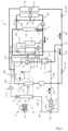
- FIG 1 and the figure 2schematically illustrate a heat treatment system 1 for several functions of a motor vehicle, among which there is at least one ventilation, heating and/or air conditioning system for the passenger compartment, an electrical storage device and at least one element of an electric drive chain of the vehicle.
- the figure 1partly represents the heat treatment system 1, while the figure 2 represents the entire heat treatment system 1 when it is produced according to a first embodiment.
- the heat treatment system 1comprises a refrigerant loop 2, which is intended in particular for the heat treatment of a vehicle interior, a first heat transfer fluid circuit 3 and a second heat transfer fluid circuit 4.
- the heat transfer fluidis in particular a heat transfer liquid such as glycolated water.
- upstreamrefers to a direction of circulation S1 of the refrigerant fluid in the refrigerant loop 2, to a direction of circulation S2 of the heat transfer fluid in the first circuit 3 of heat transfer fluid, to a direction of circulation S3 of the heat transfer fluid in the second circuit 4 of heat transfer fluid or to a direction of circulation S4 of an external air flow FA1 to the passenger compartment of the vehicle.
- the refrigerant loop 2successively comprises, according to the direction of circulation S1 of the refrigerant in the refrigerant loop 2, a compression device 20, a first heat exchanger 21 and a second heat exchanger 22, the first heat exchanger 21 and the second heat exchanger 22 being configured to implement a heat exchange between the refrigerant and the heat transfer fluid circulating in one and the other of the heat transfer fluid circuits of the heat treatment system 1.
- the first heat transfer fluid circuit 3comprises the first heat exchanger 21 while the second heat transfer fluid circuit 4 comprises the second heat exchanger 22.
- the first heat transfer fluid circuit 3also comprises at least one primary radiator 30, configured to implement a heat exchange between the heat transfer fluid and the flow of air outside FA1 to the passenger compartment of the vehicle, the primary radiator 30 being arranged downstream of the first heat exchanger 21 in the direction of circulation S2 of the heat transfer fluid in the first heat transfer fluid circuit 3.
- the first heat transfer fluid circuit 3may comprise a member 31 for circulating the heat transfer fluid, for example a pump.
- the second heat transfer fluid circuit 4further comprises at least one secondary radiator 40 configured to implement a heat exchange between the heat transfer fluid and the flow of air outside FA1 to the passenger compartment, the secondary radiator 40 being arranged upstream of the second heat exchanger 22 in the direction of circulation S3 of the heat transfer fluid in the second heat transfer fluid circuit 4.
- the second heat transfer fluid circuit 4comprises at least one element 41 for circulating the refrigerant fluid in the second circuit, for example a pump.
- the primary radiator 30 and the secondary radiator 40are exposed to the flow of outside air FA1 to the passenger compartment, the primary radiator 30 being arranged downstream of the secondary radiator 40 in the direction of circulation S4 of the flow of outside air FA1 through said radiators 30, 40. It is therefore understood that the secondary radiator 40 is crossed by the flow of outside air FA1 to the passenger compartment before the latter crosses the primary radiator 30.
- the primary radiator 30 and the secondary radiator 40are arranged on the front of the vehicle, but they could also be installed on a roof of the vehicle, in a rear wing and generally in all areas of the vehicle that can be swept by the flow of outside air FA1.
- the refrigerant loop 2consists of a closed loop which comprises at least one main branch 200 on which are arranged the compression device 20, intended to raise the pressure of the refrigerant, the first heat exchanger 21, the second heat exchanger 22, at least one expansion member, called primary expansion member 23, intended to reduce the pressure of the refrigerant, and at least one third heat exchanger 24, intended to thermally treat an interior air flow FA2, distinct from the exterior air flow FA1, and which is intended to be sent into the passenger compartment of the vehicle.
- the second heat exchanger 22can be used as a subcooler or as a condenser as required.
- the second heat exchanger 22is arranged between the first heat exchanger 21 and the primary expansion member 23, downstream of the first heat exchanger 21 in the direction of circulation S1 of the refrigerant fluid in the refrigerant loop 2. It should be noted that the different fluids circulating in the second heat exchanger 22 do not mix and that the heat exchange between these two fluids is done by conduction.
- the refrigerant loop 2thus comprises a first portion 201, between the compression device 20 and the primary expansion member 23, in which the refrigerant is subjected to a high pressure, and a second portion 202, between the primary expansion member 23 and the compression device 20, in which the refrigerant is subjected to a low pressure, lower than the high pressure.
- the refrigerant loop 2comprises an internal heat exchanger 5.
- This internal heat exchanger 5makes it possible to recover calories from the refrigerant circulating in the first portion 201 to exchange them with the refrigerant circulating at another point in the refrigerant loop 2, in particular at the level of the second portion 202.
- the internal heat exchanger 5contributes to reducing the power consumed by the compression device 20 and overall increasing the coefficient of performance of the refrigerant circuit.
- a first part 51 of the internal heat exchanger 5may be arranged on a first tube 203, called high pressure and high temperature, of the main branch 200 of the refrigerant loop 2 while a second part 52 of the internal heat exchanger 5 is arranged at a second tube 204 of the main branch 200, called low pressure and low temperature.
- the refrigerant at low temperaturebeing colder than the refrigerant at higher pressure, it is understood that the internal heat exchanger 5 allows an exchange of heat between its two parts 51, 52 and therefore between the two tubes 203, 204 of the refrigerant loop 2 on which these parts 51, 52 are arranged.
- the first part 51 of the internal heat exchanger 5is arranged between the second heat exchanger 22 and the primary expansion member 23 and the second part 52 of this internal heat exchanger 5 is arranged between the third heat exchanger 24 and the compression device 20.
- the internal heat exchanger 5allows the refrigerant fluid to be heated upstream of the compression device 20 so that this refrigerant fluid arrives in this compression device 20 in the gaseous state.
- the heat exchange implemented between the first part 51 of the internal heat exchanger 5 and the second part 52 of the internal heat exchanger 5is schematically represented by the dotted line 500.
- the main branch 200 of the refrigerant circuitmay also comprise an accumulation device 25 arranged between the third heat exchanger 24 and the second part 52 of the internal heat exchanger 5, upstream of the compression device 20.
- the accumulation device 25makes it possible to accumulate a liquid phase of the refrigerant so as to guarantee that only a gaseous phase of the refrigerant flows towards the compression device 20. Also, the accumulation device 25 makes it possible to manage the quantity of refrigerant circulating in the refrigerant loop 2.
- the refrigerant loop 2comprises a secondary branch 220 which diverges from the main branch 200 at a point of divergence 221, located between the second heat exchanger 22 and the primary expansion member 23, and which joins the main branch 200 at a point of convergence 222 located between the third heat exchanger 24 and the compression device 20.
- the secondary branch 220successively comprises, according to the direction of circulation S1 of the refrigerant fluid in the refrigerant fluid loop 2, a secondary expansion member 29 and a fourth heat exchanger 27 thermally coupled to an electrical storage device 6 of the vehicle configured to electrically power at least one element of the electric powertrain of said vehicle.
- the electrical storage device 6is included on a third heat transfer fluid circuit 8, which further comprises at least one circulator 81 intended to circulate the heat transfer fluid.
- the fourth heat exchanger 27is thus arranged in parallel with the third heat exchanger 24, from the point of view of the refrigerant fluid. It is understood that the fourth heat exchanger 27 is configured to implement a heat exchange between the refrigerant fluid circulating in the secondary branch 220 and the heat transfer fluid circulating in the third heat transfer fluid circuit 8.
- the refrigerant loop 2may comprise a bottle 26 and/or an additional expansion member, not shown, arranged between the first heat exchanger 21 and the second heat exchanger 22.
- the refrigerant loop 2comprises at least one bottle 26 installed between the first heat exchanger 21 and the second heat exchanger 22.
- the first heat transfer fluid circuit 3consists of a closed circuit which comprises a first line 310 on which are successively arranged, according to the direction of circulation S2 of the heat transfer fluid in the first heat transfer fluid circuit 3, at least the heat transfer fluid circulation member 31, the first heat exchanger 21 and the primary radiator 30.
- the first heat transfer fluid circuit 3further comprises a branch line 320 which diverges from the first line 310 at a separation point 321 between the first heat exchanger 21 and the primary radiator 30 and which joins it at a junction point 322 located between the primary radiator 30 and the heat transfer fluid circulation member 31.
- the branch line 320comprises an air heater 32 configured to implement a heat exchange between the heat transfer fluid and the interior air flow FA2 sent into the passenger compartment.
- the air heater 32 of the first heat transfer fluid circuit 3 and the third heat exchanger 24are also included in an installation 9 for air conditioning, heating and/or ventilation of the passenger compartment of the vehicle.
- said installation 9comprises at least one housing 91 for air conditioning, heating and/or ventilation, or housing 91, made of a heat-resistant synthetic material, in which the air heater 32 and the second heat exchanger 22 are arranged.
- the housing 91comprises at least one inlet vent 92, intended to bring the interior air flow FA2 into the housing 91, and a plurality of outlet vents 93, intended to send the interior air flow FA2 thermally treated by the installation 9 to different zones of the passenger compartment of the vehicle.
- the installation 9also comprises at least one fan 94 and a plurality of flaps and/or dampers 95 intended to direct the interior air flow FA2 within the housing 91, for example so that it passes through the air heater 32 or not, and into the various outlet nozzles 93.
- the first heat transfer fluid circuit 3may comprise at least one electric heating device 33 for the heat transfer fluid arranged upstream of the air heater 32 in the direction of circulation S2 of the heat transfer fluid in the first heat transfer fluid circuit 3.
- the bypass line 320ensures the bypass of the primary radiator 30.
- the first heat transfer fluid circuit 3comprises at least one means for regulating the flow rate 34 of heat transfer fluid.
- the first heat transfer fluid circuit 3may comprise two two-way valves, a first valve 341 being arranged on the bypass line 320, between the first heat exchanger 21 and the electric heating device 33 of the heat transfer fluid, and a second valve 342 being arranged on the first line 310, between the first heat exchanger 21 and the primary radiator 30.
- the first heat transfer fluid circuit 3may comprise a three-way valve arranged at the separation point 321 or the junction point 322.
- the second heat transfer fluid circuit 4consists of a closed circuit which comprises a first pipe 410 on which are successively arranged, according to the direction of circulation S3 of the heat transfer fluid in the second heat transfer fluid circuit 4, at least the heat transfer fluid circulation element 41, the second heat exchanger 22 and the secondary radiator 40.
- the second heat transfer fluid circuit 4further comprises a second pipe 420 branching off from the first pipe 410, the second pipe 420 diverging and converging from the first pipe 410 on either side of the secondary radiator 40 respectively.
- the second heat transfer fluid circuit 4further comprises a third pipe 430 which allows the heat transfer fluid to bypass either the secondary radiator 40 or a heat exchanger 43 thermally coupled to at least one element of the electric powertrain of the motor vehicle other than the electrical storage device 6.
- the third pipe 430is devoid of a heat exchanger and thus behaves as a bypass line.
- the circulation of the heat transfer fluid along the second pipe 420 and/or the first pipe 410 and/or the third pipe 430is, for example, controlled by a heat transfer fluid flow rate regulating element 42 such as a three-way valve or, alternatively, by a plurality of heat transfer fluid flow rate regulating elements 42, not shown.
- the second pipe 420comprises the heat exchanger 43 thermally coupled to at least one element of the electric powertrain of the motor vehicle, for example an electric motor and/or a control module of this electric motor, and is arranged in order, for example, to carry out a heat exchange between the heat transfer fluid circulating in the second pipe 420 and the air flow FA1 outside the passenger compartment of the vehicle.
- the external air flow FA1can ensure the cooling of the heat transfer fluid which can then capture via the heat exchanger 43 calories emitted by the element of the traction chain thermally.
- the first heat transfer fluid circuit 3 and the second heat transfer fluid circuit 4 of the heat treatment system 1are distinct, the first heat transfer fluid circuit 3 and the second heat transfer fluid circuit 4 being two closed circuits independent of each other.
- FIGS. 3 to 5represent different examples of operation of the heat treatment system 1 according to the first embodiment as shown in figure 2 .
- the solid linesrepresent pipes, lines or branches of the heat treatment system 1 in which the refrigerant fluid or the heat transfer fluid circulates
- the dotted linesrepresent pipes, lines or branches of the heat treatment system 1 in which neither the refrigerant nor the heat transfer fluid circulates.
- the indoor air flow FA2, the outdoor air flow FA1 and its circulation direction S4, a circulation direction S2 of the heat transfer fluid in the first heat transfer fluid circuit 3, a circulation direction S3 of the heat transfer fluid in the second heat transfer fluid circuit 4 and a circulation direction S1 of the refrigerant in the refrigerant loop 2are also schematically represented on the various Figures 1 to 13
- the flow regulation elements or means 34, 42 of the heat transfer fluid or the refrigerant fluidare shown as solid when they block the circulation of the fluid concerned, and hollowed out when they allow said circulation.
- FIG. 3thus illustrates a first example of operation of the heat treatment system 1 in which the refrigerant circuit 3 is configured to operate in passenger compartment cooling mode, i.e. air conditioning mode.
- the refrigerantcirculates in the main branch 200, while the secondary branch 220 is not traversed by the refrigerant.
- the circulation of the refrigerantcan be hindered by the closing of the secondary expansion member 29.
- the refrigerant fluidleaves the compression device 20 under high pressure, at high temperature and in the gaseous state towards the first heat exchanger 21 which functions as a condenser.
- the refrigerant fluidenters a first pass 211 of the first heat exchanger 21 in the gaseous state and at a temperature higher than the temperature of the heat transfer fluid circulating in a second pass 212 of the first heat exchanger 21 and transfers its calories to the heat transfer fluid.
- the refrigerant fluid thus cooledleaves the first heat exchanger 21 at least predominantly in the liquid state.
- the refrigerantis then brought to the level of the bottle 26, the liquid phase and the gas phase are separated and only the liquid phase is sent to the second heat exchanger 22.
- the refrigerant fluidthen circulates in a first pass 223 of the second heat exchanger 22, this refrigerant fluid having a temperature higher than that of the heat transfer fluid circulating in a second pass 224 of the second heat exchanger 22, the fluid refrigerant gives off calories to the heat transfer fluid.
- the second heat exchanger 22is configured to ensure the subcooling of the refrigerant, that is to say that the temperature difference between the refrigerant in the liquid state and the heat transfer fluid allows cooling of the refrigerant to a temperature lower than its condensation temperature.
- the refrigerant fluid leaving the second heat exchanger 22, in the liquid state,is sent to the first part 51 of the internal heat exchanger 5 where it is involved in a heat exchange as previously described, then the refrigerant fluid is brought to the primary expansion member 23 in which it undergoes a reduction in its pressure.
- the refrigerantjoins the third heat exchanger 24, used as an evaporator, in which it is evaporated by capturing calories from the interior air flow FA2.
- the interior air flow FA2is cooled and sent to the passenger compartment of the vehicle while the refrigerant leaves the third heat exchanger 24.
- the refrigerantthen joins the accumulation device 25 in which the liquid phase and the gas phase are separated and the gas phase is sent to the second part 52 of the internal heat exchanger 5 then, again, to the compression device 20.
- the heat transfer fluiddoes not circulate in the bypass line 320 and the circulation of the heat transfer fluid takes place essentially at the level of the first line 310, such circulation being ensured by the selective opening and closing of the different means for regulating the flow rate 34 of the heat transfer fluid included in the first heat transfer fluid circuit 3, here the closing of the first two-way valve 341 and the opening of the second two-way valve 342.
- the heat transfer fluidis circulated in the first heat transfer fluid circuit 3 by the circulation member 31.
- the heat transfer fluidis brought to the first heat exchanger 21 and circulates in the second pass 212 of the first heat exchanger 21.
- the heat transfer fluidcolder than the refrigerant fluid circulating in the first pass 211 of the first heat exchanger 21, is heated by the heat exchange carried out with the refrigerant fluid.
- the heat transfer fluidthen circulates along the first line 310, passes through the separation point 321 and is then sent to the primary radiator 30.
- the heat transfer fluid entering the primary radiator 30being at a temperature higher than the temperature of the outside air flow FA1, the heat transfer fluid gives off calories to the flows outside air FA1 and the latter is heated.
- the heat transfer fluid leaving the primary radiator 30, cooled,is then returned to the circulation member 31.
- the heat transfer fluidflows through the first pipe 410 and the second pipe 420, the partial closure of the heat transfer fluid flow regulating element 42 preventing the circulation of the heat transfer fluid in the third pipe 430.
- the heat transfer fluidis circulated in the second heat transfer fluid circuit 4 by the circulation element 41.
- the heat transfer fluidis brought into the second heat exchanger 22. As previously explained, it circulates in the second pass 224 of the second heat exchanger 22.
- the heat transfer fluidbeing colder than the liquid refrigerant fluid circulating in the first pass 223 of the second heat exchanger 22, the heat transfer fluid captures the calories from the refrigerant fluid, thus ensuring the subcooling of the latter.
- the heat transfer fluidleaves the second heat exchanger 22 heated and is brought to the secondary radiator 40.
- the secondary radiator 40is arranged upstream of the primary radiator 30 in the direction of circulation of the outside air flow FA1 through the primary radiator 30 and secondary radiator 40.
- the outside air flow FA1colder than the heat transfer fluid entering the secondary radiator 40 and then the primary radiator 30 respectively, thus initially passes through the secondary radiator 40, captures the calories of the heat transfer fluid circulating in the secondary radiator 40, then the heated outside air flow FA1 passes through the primary radiator 30 at which it captures the calories of the heat transfer fluid circulating in the primary radiator 30.
- the cooled heat transfer fluid leaving the secondary radiator 40is then returned to the circulation element 41 and then to the second heat exchanger 22.
- the cooled heat transfer fluid leaving the secondary radiator 40can also circulate in the second pipe 420 and thus capture the calories present in the heat exchanger 43 thermally coupled to at least one element of the electric powertrain of the motor vehicle.
- the second heat transfer fluid circuit 4is therefore configured so that the secondary radiator 40 discharges into the exterior air flow FA1 the calories captured at the level of the first heat exchanger 21 and at the level of the heat exchanger 43 thermally coupled to at least one element of the electric drive chain of the motor vehicle.
- the secondary radiator 40involved in the first heat exchange with the outside air flow FA1, is arranged in series with the second heat exchanger 22 which is configured to provide subcooling of the refrigerant fluid after its condensation phase.
- the primary radiator 30, involved in the second heat exchange with the outside air flow FA1 which has been heated a first time by heat exchange by passing through the secondary radiator 40,is arranged in series with the first heat exchanger 21, which is configured to condense the refrigerant fluid and therefore requires a smaller temperature difference between the heat transfer fluid and the refrigerant fluid than the second heat exchanger 22 used as a subcooler.
- the heat treatment system 1operates in passenger compartment cooling mode, i.e. it allows fresh air to be sent into the passenger compartment of the vehicle.
- FIG 4illustrates a second example of operation of the heat treatment system 1 according to the first embodiment implementing a passenger compartment cooling mode and a cooling mode of the electrical storage device 6, which can, for example, be implemented during a rapid charging phase of said electrical storage device 6.
- This second mode of operationdiffers from the first mode of operation in that, in the refrigerant loop 2, the refrigerant leaving the second heat exchanger 22, subcooled, is separated into two refrigerant flows at the point of divergence 221.
- a first refrigerant flowcontinues to circulate on the main branch 200 and follows a path identical to that previously described with reference to the figure 3 .
- a second flow of refrigerant fluidis sent to the secondary branch 220.
- the secondary expansion member 29is partially open and allows the circulation of the refrigerant fluid in said secondary branch 220, causing a expansion thereof.
- the second flow of refrigerant fluidis directed towards the secondary expansion member 29 in which it undergoes expansion before joining the fourth heat exchanger 27.
- the refrigerant fluid circulating in a first pass 271 of the fourth heat exchanger 27captures calories from the heat transfer fluid circulating in a second pass 272 of the fourth heat exchanger 27.
- the refrigerantleaves the fourth heat exchanger 27 in predominantly gaseous form and reaches the convergence point 222 at which the first refrigerant flow and the second refrigerant flow are combined in order to be directed to the accumulation device 25.
- the heat transfer fluid which has been cooled in the fourth heat exchanger 27circulates in the third heat transfer fluid circuit 8 so as to cool the electrical storage device 6.
- FIG. 5schematically represents a third example of operation of the heat treatment system 1 according to which the refrigerant loop 2 operates in passenger compartment heating mode, that is to say it operates the heating of the interior air flow FA2 before it is sent into the passenger compartment of the vehicle, and according to a heat recovery mode on the electrical storage device 6.
- the third heat exchanger 24is inactive, in the sense that it is not crossed by the refrigerant.
- the refrigerant fluidleaves the compression device 20 in a gaseous state, at high pressure and at high temperature, and is supplied to the first heat exchanger 21.
- the first heat exchanger 21is used as a condenser and the refrigerant fluid circulating in the first pass 211 of the first heat exchanger 21 is cooled by heat exchange with the heat transfer fluid circulating in the second pass 212 of the first heat exchanger 21.
- the cooled refrigerant fluidis sent to the bottle 26 then the liquid portion of the refrigerant fluid is sent to the second heat exchanger 22 for its subcooling by heat exchange with the heat transfer fluid circulating in the second pass 224 of the second heat exchanger 22.
- the refrigerant fluid leaving the second heat exchanger 22, subcooled,is then brought to the divergence point 221.
- the primary expansion member 23, included in the main branch 200is closed, while the secondary expansion member 29, included in the secondary branch 220, is open.
- the circulation of the refrigerant fluid in the remainder of the main branch 200is hindered and the refrigerant fluid is sent into the secondary branch 220 so as to bypass the third heat exchanger 24.
- the refrigerant fluidis sent to the secondary expansion member 29, in which it is expanded, then the low pressure and low temperature fluid is brought to the fourth heat exchanger 27, thermally coupled to the third heat transfer fluid circuit 8 and therefore to the electrical storage device 6.
- the third heat exchanger 24operates as an evaporator, a temperature of this refrigerant fluid being lower than a temperature of the heat transfer fluid which circulates in the second pass 272 of the fourth heat exchanger 27, the refrigerant fluid captures the calories of the heat transfer fluid circulating in the third heat transfer fluid circuit 8, said heat transfer fluid then ensuring the cooling of the electrical storage device 6 of the vehicle.
- the calories transferred by the electrical storage device 6 to the heat transfer fluid of the third heat transfer fluid circuit 8are recovered and make it possible to heat the refrigerant fluid of the refrigerant fluid loop 2 upstream of the compression device 20.
- the refrigerant fluidthus leaves the fourth heat exchanger 27 in an at least partially gaseous state and then joins the convergence point 222 then the accumulation device 25 on the main branch 200.
- the heat transfer fluidis circulated by the circulation member 31, then is sent to the first heat exchanger 21 in which it captures the calories from the refrigerant fluid circulating in the first pass 211 of the first heat exchanger 21, the heat transfer fluid is then brought to the separation point 321 of the first heat transfer fluid circuit 3.
- the flow rate regulation means 34 of the heat transfer fluidare configured to hinder the circulation of the heat transfer fluid in the remainder of the first line 310 and to send the heat transfer fluid to the bypass line 320.
- the first valve 341 two-way valveis open while the second two-way valve 342 is closed and the heat transfer fluid bypasses the primary radiator 30 which is then inactive.
- the heated heat transfer fluidcirculates in the bypass line 320 to the electric heating device 33 which will ensure the heating of said heat transfer fluid.
- the heated heat transfer fluidis then sent to the air heater 32 in which it implements a heat exchange with the interior air flow FA2.
- the heat transfer fluidhotter than the interior air flow FA2, gives up calories to the interior air flow FA2 which is thus heated then sent to the passenger compartment via at least one of the outlet nozzles of the housing 91.
- the cooled heat transfer fluidthen leaves the air heater 32 and is returned to the first line 310 of the first heat transfer fluid circuit 3, towards the circulation member 31.
- the path of the heat transfer fluidis substantially identical to that previously described with reference to the figure 4 , that is to say that the heat transfer fluid is circulated by the circulation element 41 then passes through the second heat exchanger 22, and possibly the heat exchanger 43 thermally coupled to at least one element of the electric drive chain of the motor vehicle.
- FIG. 6represents a second embodiment of the heat treatment system 1 in which the first heat transfer fluid circuit 3 and second heat transfer fluid circuit 4 are identical to what has previously been explained with reference to Figures 1 to 5 , the first heat transfer fluid circuit 3 and the second heat transfer fluid circuit 4 being distinct and independent of each other.
- the refrigerant loop 2is substantially identical to what was previously explained with reference to the first embodiment, it nevertheless differs from the latter in that it comprises an additional expansion member 28 in place of, or in addition to, the bottle 26 arranged between the first heat exchanger 21 and the second heat exchanger 22, on the main branch 200 of the refrigerant loop 2.
- the refrigerant fluid loop 2successively comprises, according to the direction of circulation S1 of the refrigerant fluid in the refrigerant fluid loop 2, the compression device 20, the first heat exchanger 21, the additional expansion member 28 and the second heat exchanger 22.
- the refrigerant loop 2can successively comprise, according to the direction of circulation S1 of the refrigerant in the refrigerant loop 2, the compression device 20, the first heat exchanger 21, the bottle 26, the additional expansion member 28 and the second heat exchanger 22, so as to ensure that only a liquid portion of the refrigerant leaving the first heat exchanger 21 is sent to the additional expansion member 28.
- the heat treatment system 1When the heat treatment system 1 is produced according to this second embodiment, it can be used to implement a mode of cooling the passenger compartment or a mode of cooling the passenger compartment and cooling the electrical storage device 6, not shown, as they have been previously explained for the first embodiment with reference to figures 4 And 5 respectively.
- the descriptions made with reference to these figuresare transposable to the heat treatment system 1 produced according to the present embodiment with the difference that instead of, or in addition to, the bottle 26, the refrigerant loop 2 comprises the additional expansion member 28.
- the additional expansion member 28is then open and allows the refrigerant fluid to pass towards the second heat exchanger 22 without ensuring its expansion so that the path and the changes of state of the refrigerant fluid in the refrigerant loop 2 are strictly identical to those previously explained.
- the heat treatment system 1When the heat treatment system 1 according to the present embodiment implements the heating and heat recovery mode, it can also implement the cooling of at least one of the elements of the chain of the electric traction chain. Such an operating mode is shown in figure 7 .
- the refrigerantleaves the compression device 20 under high pressure, at high temperature and in the gaseous state towards the first heat exchanger 21 which functions as a condenser.
- the refrigerantgives up calories to the heat transfer fluid circulating in the second pass 212 of the first heat exchanger 21 and leaves the first heat exchanger 21 in the essentially liquid state, or even entirely liquid.
- the cooled refrigerantis brought to the additional expansion member 28 at the level of which it undergoes a first expansion.
- the outgoing refrigerant, at low pressure and low temperature,is then sent to the second heat exchanger 22.
- the second heat exchanger 22operates as an evaporator.
- the refrigerant fluid, colder than the heat transfer fluid circulating in the second pass 224 of the second heat exchanger 22,captures the calories from the latter, and leaves the second heat exchanger 22 heated and in an at least partially gaseous or two-phase state.
- the second heat transfer fluid circuit 4makes it possible to cool at least one of the elements of the drive chain arranged on the second pipe 420, by means of the heat exchanger 43 thermally coupled to at least one element of the electric drive chain of the motor vehicle.
- the refrigerant leaving the second heat exchanger 22is then brought to the level of the divergence point 221.
- the primary expansion member 23is closed so as to hinder the circulation of the refrigerant in the remainder of the main branch 200, while the secondary expansion member 29 is partially open so as to allow the circulation of the refrigerant in the secondary branch 220 and to ensure the expansion of said fluid.
- the refrigerant fluidis thus directed on the secondary branch 220 to the secondary expansion member 29 at which it undergoes a second expansion, at a lower level than the first expansion implemented by the additional expansion member 28.
- the refrigerant fluidleaves the secondary expansion member 29 at low pressure and in the liquid state and is brought to the fourth heat exchanger 27 in which, as previously explained, it captures the calories from the heat transfer fluid circulating in the second pass 272 of the fourth heat exchanger 27 so as to allow the cooling of the electrical storage device 6.
- the calories released by the electrical storage device 6make it possible to heat the refrigerant fluid of the refrigerant loop 2 upstream of the compression device 20.
- the refrigerant fluidthus leaves the fourth heat exchanger 27 in an at least partially gaseous state and then joins the convergence point 222, then the accumulation device 25 on the main branch 200.
- the secondary expansion member 29can be completely open so as to allow the circulation of the refrigerant fluid along the secondary branch 220 without expanding it.
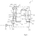
- FIGs 8 to 13illustrate a third embodiment and a fourth embodiment of the heat treatment system 1 in which the first heat transfer fluid circuit 3 and the second heat transfer fluid circuit 4 are interconnected.
- figure 8partly illustrates the heat treatment system 1 according to the third embodiment, while the figure 9 represents the whole of this same heat treatment system 1.
- the portion of heat treatment system 1 shown in figure 8is substantially identical to that previously described with reference to the figure 1 , it is nevertheless distinguished from the latter by the arrangement of the second circuit 4 of heat transfer fluid in the heat treatment system 1.
- FIG 8shows that the circulation member 31 draws in a flow of heat transfer fluid illustrated by a+b and pushes this flow a+b into the first line 310 of the first heat transfer fluid circuit 3.
- the heat transfer fluidsplits into a first flow a which enters the second heat transfer fluid circuit 4 and a second flow b which continues its path in the first heat transfer fluid circuit 3.
- the first flow a and the second flow bare joined at the connection point 412, before returning to the circulation member 31.
- the second heat transfer fluid circuit 4extends between a bifurcation point 411 and a connection point 412.
- the bifurcation point 411is arranged on the first heat transfer fluid circuit 3 upstream of the primary radiator 30 in the direction of circulation S2 of the heat transfer fluid in the first heat transfer fluid circuit 3. More specifically, the bifurcation point 411 is arranged between the first heat exchanger 21 and the primary radiator 30.
- the connection point 412is arranged on the first heat transfer fluid circuit 3, upstream of the first heat exchanger 21 in the direction of circulation S2 of the heat transfer fluid in the first heat transfer fluid circuit 3. More specifically, the connection point 412 is arranged between the primary radiator 30 and the first heat exchanger 21.
- the heat treatment system 1comprises at least one heat transfer fluid flow rate regulating member 44 arranged at the bifurcation point 411, as illustrated, or at the connection point 412.
- the refrigerant fluid flow rate regulating member 44may be a three-way valve.
- the heat treatment system 1may comprise a plurality of flow regulating members 44 of the heat transfer fluid, for example two-way valves, respectively arranged on the first line 310 of the first heat transfer fluid circuit 3 and on the first pipe 410 of the second heat transfer fluid circuit 4.
- the heat treatment system 1comprises the heat transfer fluid circulation member 31, arranged on the first line 310 of the first heat transfer fluid circuit 3, but may be devoid of the circulation element 41 of the second heat transfer fluid circuit 4 as previously described.
- FIG 9represents the heat treatment system 1 as a whole, when it is produced according to the third embodiment as described with reference to the figure 8 .
- the refrigerant fluid loop 2is identical to that previously described with reference to the Figures 1 to 7 for the first and second embodiments of the present invention.
- the heat transfer fluid loop 6may comprise the bottle 26 and/or the additional expansion member as previously described.
- the refrigerant fluid loop 2will comprise only the bottle 26.
- the first line 310is identical to that previously described for the first and second embodiments.
- the bypass line 320comprises the air heater 32, configured to implement a heat exchange between the heat transfer fluid and the interior air flow FA2 sent into the passenger compartment of the vehicle, and the bypass line 320 extends between the separation point 321 and the junction point 322.
- the separation point 321is arranged downstream of the first heat exchanger 21 in the direction of circulation S2 of the heat transfer fluid in the first heat transfer fluid circuit 3, more specifically between the first heat exchanger 21 and the primary radiator 30.
- the third embodimentdiffers from the first and second embodiments in that the junction point 322 of the bypass line 320 is arranged on the second heat transfer fluid circuit 4, upstream of the second heat exchanger 22 in the direction of circulation S3 of the heat transfer fluid in the second heat transfer fluid circuit 4, the junction point 322 being arranged between the secondary radiator 40 and the second heat exchanger 22.
- the second pipe 420comprises, as previously explained, the heat exchanger 43 thermally coupled to at least one of the elements of the electric powertrain of the motor vehicle and the second pipe 420 diverges and converges from the first pipe 410 on either side of the secondary radiator 40 respectively.
- the third pipe 430is placed in parallel with this heat exchanger 43 thermally coupled to at least one of the elements of the electric powertrain and in parallel with the secondary radiator 40, so that the heat transfer fluid can bypass these components depending on the position taken by the flow control member 42.
- FIG. 10represents the heat treatment system 1 according to the third embodiment when it operates in a passenger compartment cooling mode.
- the architecture of the refrigerant loop 2 and the path of the refrigerant in said loop 2are identical to what was previously described for the heat treatment system 1 produced according to the first embodiment.
- the description of the refrigerant loop 2 made for the passenger compartment cooling mode with reference to the figure 3is transposable to the present embodiment.
- the heat transfer fluidis circulated in the first heat transfer fluid circuit 3 by the circulation member 31, the heat transfer fluid is sent to the first heat exchanger 21 where it circulates in the second pass 212 of the first heat exchanger 21 and captures the calories of the refrigerant fluid, hotter, circulating in the first pass 211 of the first heat exchanger 21.
- the heat transfer fluid leaving the first heat exchanger 21, reheated,is then brought to the separation point 321.
- the means for regulating the flow rate 34 of the heat transfer fluidare configured to hinder the circulation of the heat transfer fluid towards the bypass line 320.
- the first two-way valve 341is thus closed while the second two-way valve 342 is open.
- the heat transfer fluidthus circulates along the first line 310 of the first circuit 3 of heat transfer fluid up to the bifurcation point 411.
- the flow rate regulating member 44 of the heat transfer fluidis open so as to allow the simultaneous circulation of a first flow of heat transfer fluid in the first line 310 of the first heat transfer fluid circuit 3 and a second heat transfer fluid flow in the first pipe 410 of the second heat transfer fluid circuit 4.
- the heat transfer fluidthus circulates in parallel in the primary radiator 30 and in the secondary radiator 40.
- the first flow of heat transfer fluidwhich continues to circulate along the first line 310 of the first circuit 3 of heat transfer fluid, is sent to the primary radiator 30.
- the heat transfer fluidhotter than the flow of outside air FA1 in the passenger compartment, gives up calories to the flow of outside air FA1 and is cooled.
- This first flow of heat transfer fluidthen circulates along the first line 310 of the first circuit 3 of heat transfer fluid to the circulation member 31.
- the second heat transfer fluid flowsent into the first pipe 410 of the second heat transfer fluid circuit 4, circulates to the secondary radiator 40.
- the heat transfer fluidhotter than the outside air flow FA1 gives up calories to this outside air flow FA1.
- the cooled heat transfer fluidcirculates in the first pipe 410 of the second heat transfer fluid circuit 4 to the second heat exchanger 22. Similar to what was previously explained for the first and second embodiments, the heat transfer fluid circulating in the second pass 224 of the second heat exchanger 22 captures the calories from the refrigerant fluid circulating in the first pass 223 of the second heat exchanger 22 and ensures the subcooling of the latter.
- the heat transfer fluid leaving the second heat exchanger 22is then brought to the connection point 412 at which it joins the first line 310 of the first heat transfer fluid circuit 3, is combined with the first flow of heat transfer fluid, then is returned to the heat transfer fluid circulation member 31.
- the heat transfer fluid circulating in the secondary radiatoris thus crossed by the flow of outside air subjected to the ambient temperature, that is to say the lowest available in the air outside the passenger compartment.
- the subcooling which takes place in the second heat exchanger 22is therefore ensured with the coldest air available.
- the air flow FA1 heated by the secondary radiator 40passes through the primary radiator 30 at a temperature which nevertheless allows the condensation of the refrigerant fluid at the heart of the first heat exchanger 21.
- the heat transfer fluid flow regulating element 42is placed in a position where the second pipe 420 is isolated from the second heat transfer fluid circuit 4. Circulation can nevertheless take place in a loop formed by the third pipe 430 and by the second pipe 420, by operating the heat transfer fluid circulation element 41.
- the heat transfer fluid flow regulating element 42is placed in a position where the calories captured at the heat exchanger 43 thermally coupled to at least one of the elements of the electric drive chain are discharged into the outside air flow FA1 via the secondary radiator 40.
- the heat treatment system 1does not, in the present operating mode, support the cooling of the electrical storage device 6.
- FIG 11represents an example of a second mode of operation of the heat treatment system 1 according to the third embodiment when the latter implements a passenger compartment cooling mode and a cooling mode of the electrical storage device 6, for example implemented during a rapid charging phase of said electrical storage device 6.
- the path of the heat transfer fluid in the first heat transfer fluid circuit 3 and in the second heat transfer fluid circuit 4is identical to that previously explained with reference to the figure 10 for the cooling mode of the passenger compartment of the heat treatment system 1 according to the third embodiment, the description given of the path of the heat transfer fluid in these two circuits 3, 4 is thus transposable to the present operating mode.
- This second operating modeis distinguished from the first operating mode of the heat treatment system 1 according to the third embodiment in that the refrigerant fluid leaving the second heat exchanger 22, subcooled, is separated into two flows of refrigerant fluid at the level of the point of divergence 221.
- the first flow of refrigerant fluidcontinues to circulate on the main branch 200 while the second flow of refrigerant fluid is sent on the secondary branch 220, towards the secondary expansion member 29.
- the second flow of liquid refrigerant fluidis expanded in the secondary expansion member 29 and is then brought into the fourth heat exchanger 27 in which it captures calories from the heat transfer fluid circulating in the second pass 272 of the fourth heat exchanger 27.
- the refrigerant fluidleaves the fourth exchanger in an at least partially gaseous state and reaches the convergence point 222 in order to be directed towards the accumulation device 25.
- the heat transfer fluid which has been cooled in the fourth heat exchanger 27circulates in the third heat transfer fluid circuit 8 so as to cool the electrical storage device 6.
- FIG 12illustrates an example of a third operating mode in which the heat treatment system 1 according to the third embodiment simultaneously implements a heating mode of the interior air flow FA2 sent to the passenger compartment and a heat recovery mode.
- the present operating modeis substantially identical to the heating and calorie recovery mode previously described for the first embodiment with reference to the figure 5 , the description of the refrigerant loop 2 and the path of the refrigerant in said loop 2 is therefore transposable to the present embodiment.
- the heat transfer fluidis successively circulated by the circulation member 31, sent into the first heat exchanger 21, in which it captures the calories from the refrigerant fluid circulating in the first pass 211 of the first heat exchanger 21, then is brought to the separation point 321 of the first heat transfer fluid circuit 3.
- the first two-way valve 341When the heat treatment system 1 operates in heating and heat recovery mode, the first two-way valve 341 is open while the second two-way valve 342 is closed, these means for regulating the flow rate 34 of the heat transfer fluid hinder the circulation of the heat transfer fluid in the remainder of the first line 310 and send the heat transfer fluid to the bypass line 320 of the first refrigerant circuit so as to bypass the primary radiator 30 which is then inactive.
- the heated heat transfer fluidcirculates in the bypass line 320 to the electric heating device 33 which will provide additional heating of said heat transfer fluid, then the heat transfer fluid is brought into the air heater 32.
- the heat transfer fluidhotter than the interior air flow FA2, gives off calories to the interior air flow FA2 which is thus heated then sent to the passenger compartment via at least one of the outlet nozzles of the housing 91.
- the cooled heat transfer fluidthen leaves the air heater 32 and circulates along the bypass line 320 to the junction point 322.
- the heat transfer fluidis then brought to the first pipe 410 of the second heat transfer fluid circuit 4, between the secondary radiator 40 and the second heat exchanger 22.
- the heat transfer fluidcirculates in the second pass 224 of the second heat exchanger 22 within which it implements a heat exchange with the refrigerant fluid circulating in the first pass 223 of the second heat exchanger 22.
- the heat transfer fluidcaptures the calories of said refrigerant fluid so as to allow the subcooling of the latter and then the heat transfer fluid circulates along the first pipe 410 to the connection point 412 and is returned on the first line 310 of the first heat transfer fluid circuit 3 to the circulation member 31.
- the heat transfer fluid flow regulating element 42is placed in a position where the second pipe 420 is isolated from the second heat transfer fluid circuit 4. Circulation can nevertheless take place in a loop formed by the third pipe 430 and by the second pipe 420, by operating the heat transfer fluid circulation element 41.
- the heat transfer fluid flow regulating element 42is placed in a position where the calories captured at the heat exchanger 43 thermally coupled to at least one of the elements of the electric drive chain are discharged into the outside air flow FA1 via the secondary radiator 40.
- FIG 13represents the processing system when it is implemented according to the fourth embodiment of the present invention.
- This fourth embodimentis substantially identical to the third embodiment, shown in Figures 8 to 12 .
- the description of the heat treatment system 1 according to the third embodiment, made with reference to the figure 9is transposable to the present embodiment.
- This fourth embodimentis distinguished from the third embodiment by the positioning of the bifurcation point 411 of the first pipe 410 of the second circuit 4 of heat transfer fluid.
- the bifurcation point 411is arranged downstream of the primary radiator 30 in the direction of circulation S2 of the heat transfer fluid in the first heat transfer fluid circuit 3, the bifurcation point 411 being arranged between the primary radiator 30 and the first heat exchanger 21.
- the control of the circulation of the heat transfer fluid in the first line 310 of the first heat transfer fluid circuit 3 and/or in the first pipe 410 of the second heat transfer fluid circuit 4is implemented by at least one heat transfer fluid flow rate regulating member 44, such as a three-way valve, which may, for example, be arranged at the bifurcation point 411 or the connection point 412.
- the heat treatment system 1may comprise a plurality of heat transfer fluid flow rate regulating members 44 arranged on the first pipe 410 and on the first line 310.
- FIG 14illustrates an example of operation of the heat treatment system 1 according to the fourth embodiment when the latter implements a passenger compartment cooling mode.
- the architecture of the refrigerant fluid loop 2 and the path of the refrigerant fluid in said circuitare identical to what was previously described for the heat treatment system 1 produced according to the third embodiment operating according to the cooling mode, thus, the description made with reference to the figure 10 is transposable to the present embodiment.
- the path of the heat transfer fluidis also identical between the circulation member 31 and the separation point 321.
- the means for regulating the flow rate 34 of the heat transfer fluidare configured to hinder the circulation of the heat transfer fluid to the bypass line 320.
- the first two-way valve 341is thus closed while the second two-way valve 342 is open.
- the heat transfer fluidcirculates along the first line 310 of the first heat transfer fluid circuit 3 to the primary radiator 30 at which the heat transfer fluid, hotter than the outside air flow FA1 to the passenger compartment, gives off calories to the outside air flow FA1.
- the outgoing heat transfer fluid, cooled,then circulates along the first line 310 of the first heat transfer fluid circuit 3 to the bifurcation point 411.
- the flow regulating member 44 of heat transfer fluidis open so as to simultaneously allow the circulation of the fluid heat transfer fluid along the remainder of the first line 310 of the first heat transfer fluid circuit 3 and along the first pipe 410 of the second heat transfer fluid circuit 4.
- the first heat transfer fluid flowcontinues to circulate along the first line 310 of the first heat transfer fluid circuit 3 towards the circulation member 31 while the second heat transfer fluid flow is sent to the first pipe 410 of the second heat transfer fluid circuit 4, towards the secondary radiator 40.
- the second flow of heat transfer fluidis advantageously involved in two successive heat exchanges with the flow of external air FA1, respectively in the primary radiator 30 then in the secondary radiator 40.
- the heat transfer fluid flow rate regulating member 44can be configured so that the second heat transfer fluid flow circulates at a lower flow rate in the first pipe 410, and therefore in the secondary radiator 40.
- the second cooled heat transfer fluid flowis then, as previously explained, sent along the first pipe 410 to the second heat exchanger 22, in which it allows the subcooling of the refrigerant circulating in the first pass 223 of the second heat exchanger 22.
- the second heat transfer fluid flowthen joins, as previously explained, the first heat transfer fluid flow at the connection point 412 arranged in the first line 310 of the first heat transfer fluid circuit 3 and is then returned to the circulation member 31.
- this fourth embodimentmakes it possible to maximize the subcooling of the refrigerant fluid while minimizing the operating costs of the heat treatment system 1, and in particular the utility requirements of the second heat exchanger 22.
- the heat treatment system 1 according to the fourth embodimentcan also implement the mode of cooling the passenger compartment and cooling the electrical storage device 6, not shown, as previously explained for the third embodiment with reference to the figure 10 .
- the refrigerant loop 2operates in a similar manner to what has been explained for the third operating mode. Also, the description of the refrigerant loop 2 and of the path of the refrigerant in said loop 2 made with reference to the figure 10 can be transposed to the present fourth embodiment. Similarly, the circulation of the heat transfer fluid in the first heat transfer fluid circuit 3 and in the second heat transfer fluid circuit 4 is identical to what has been described in the passenger compartment cooling mode of the fourth embodiment, with reference to the figure 14 of this document.
- the heat treatment system 1 according to the fourth embodimentcan also implement the heating and calorie recovery mode, not shown, as set out above for the third embodiment with reference to the figure 12 .
- the refrigerant fluid loop 2, the first heat transfer fluid circuit 3 and the second heat transfer fluid circuit 4operating in a similar manner to that set out for the third operating mode, the description made with reference to the figure 12 and the third embodiment can be fully transposed to the present fourth embodiment.
- the present inventionthus proposes a heat treatment system comprising a refrigerant loop, a first heat transfer fluid circuit and a second heat transfer fluid circuit, the first heat transfer fluid loop comprising a primary radiator and the second heat transfer fluid circuit comprising a secondary radiator, the primary radiator being arranged downstream of the secondary radiator in a direction of circulation of the outside air flow through said radiators.
- the first heat transfer fluid circuitcomprises in particular at least one first heat exchanger configured to operate as a condenser of the refrigerant circulating in the refrigerant loop while the second heat transfer fluid circuit comprises at least one second heat exchanger configured to implement the subcooling of the refrigerant circulating in this same refrigerant loop.
- the present inventioncannot, however, be limited to the means and configurations described and illustrated here and it also extends to any technically operative combination of such means.
- the architecture of the refrigerant fluid loop and the architecture of the first heat transfer fluid circuit and/or the second heat transfer fluid circuitmay be modified without harming the invention to the extent that they make it possible to fulfill the functionalities of the heat treatment system 1 described and illustrated in this document.
Landscapes
- Engineering & Computer Science (AREA)
- Mechanical Engineering (AREA)
- Thermal Sciences (AREA)
- Physics & Mathematics (AREA)
- Life Sciences & Earth Sciences (AREA)
- Sustainable Development (AREA)
- Sustainable Energy (AREA)
- Combustion & Propulsion (AREA)
- Chemical & Material Sciences (AREA)
- Power Engineering (AREA)
- Transportation (AREA)
- Air-Conditioning For Vehicles (AREA)
- Cooling, Air Intake And Gas Exhaust, And Fuel Tank Arrangements In Propulsion Units (AREA)
Description
Translated fromFrenchLa présente invention se rapporte au domaine des boucles de fluide caloporteur fonctionnant avec une boucle de fluide réfrigérant. L'invention a pour objet un système de traitement thermique comprenant au moins deux circuits de fluide caloporteur et une boucle de fluide réfrigérant.The present invention relates to the field of heat transfer fluid loops operating with a refrigerant fluid loop. The invention relates to a heat treatment system comprising at least two heat transfer fluid circuits and a refrigerant fluid loop.
Un tel système de traitement thermique est connu du document
Une boucle de fluide réfrigérant est généralement associée à une installation de ventilation, de chauffage et/ou de climatisation d'un habitacle de véhicule pour traiter thermiquement un flux d'air extérieur au véhicule se dirigeant vers l'habitacle. En effet, une telle boucle permet, à l'aide des changements d'état du fluide réfrigérant, de chauffer et/ou de refroidir le flux d'air envoyé à l'intérieur de l'installation de ventilation, de chauffage et/ou de climatisation.A refrigerant loop is generally associated with a ventilation, heating and/or air conditioning system for a vehicle passenger compartment to thermally treat an air flow from outside the vehicle heading towards the passenger compartment. Indeed, such a loop makes it possible, using changes in the state of the refrigerant, to heat and/or cool the air flow sent inside the ventilation, heating and/or air conditioning system.
Dans une autre application de cette boucle de fluide réfrigérant, il est connu de l'utiliser pour refroidir un dispositif de stockage électrique du véhicule, ce dernier étant utilisé pour fournir une énergie à un moteur électrique capable de mettre en mouvement le véhicule. La boucle de fluide réfrigérant fournit ainsi l'énergie capable de refroidir le dispositif de stockage électrique pendant son utilisation en phases de roulage. La boucle de fluide réfrigérant est ainsi dimensionnée pour refroidir ce dispositif de stockage électrique.In another application of this refrigerant loop, it is known to use it to cool an electrical storage device of the vehicle, the latter being used to supply energy to an electric motor capable of setting the vehicle in motion. The refrigerant loop thus supplies the energy capable of cooling the electrical storage device during its use in driving phases. The refrigerant loop is thus sized to cool this electrical storage device.
Lors de son fonctionnement, la boucle de fluide réfrigérant peut être soumise à de fortes contraintes qui l'amènent aux limites de ses capacités.During operation, the refrigerant loop can be subjected to high stresses which bring it to the limits of its capacities.
C'est notamment le cas quand le dispositif de stockage électrique est utilisé d'une manière qui provoque un échauffement important de celui-ci, par exemple lors d'une phase de charge rapide du dispositif de stockage. La charge rapide consiste à charger le dispositif de stockage électrique sous une tension et un ampérage élevés de manière à charger le dispositif de stockage électrique en un temps court de quelques dizaines de minutes. Cette charge rapide implique un échauffement du dispositif de stockage électrique qu'il convient de traiter.This is particularly the case when the electrical storage device is used in a manner that causes significant heating thereof, for example during a rapid charging phase of the storage device. Rapid charging consists of charging the electrical storage device at a high voltage and amperage so as to charge the electrical storage device in a short time of a few tens of minutes. This rapid charging involves heating of the electrical storage device that must be addressed.
Par ailleurs, lors d'une phase de charge rapide, il peut être nécessaire de maintenir un niveau de confort thermique acceptable à l'intérieur de l'habitacle, c'est-à-dire que la boucle de fluide réfrigérant peut être amenée à devoir simultanément assurer le traitement thermique de l'habitacle et le traitement thermique du dispositif de stockage. Un tel fonctionnement de la boucle de fluide réfrigérant peut être observé soit car les occupants du véhicule restent à l'intérieur du véhicule pendant tout ou partie du temps de charge mentionné ci-dessus, soit pour anticiper le retour de ces occupants et éviter tous désagrément d'ordre thermique. Ces deux demandes en refroidissement impliquent une performance du système de traitement qui requiert un dimensionnement du système qui le rend peu compatible avec les contraintes des véhicules automobiles actuels, notamment les véhicules mus par un moteur électrique.Furthermore, during a fast charging phase, it may be necessary to maintain an acceptable level of thermal comfort inside the passenger compartment, i.e. the refrigerant loop may be required to simultaneously provide thermal treatment of the passenger compartment and thermal treatment of the storage device. Such operation of the refrigerant loop may be observed either because the occupants of the vehicle remain inside the vehicle for all or part of the charging time mentioned above, or to anticipate the return of these occupants and avoid any thermal inconvenience. These two cooling demands imply a performance of the treatment system which requires a dimensioning of the system which makes it incompatible with the constraints of current motor vehicles, in particular vehicles powered by an electric motor.
Afin d'optimiser les performances du circuit de fluide réfrigérant, il est connu d'intégrer au moins un échangeur thermique configuré pour permettre le sous-refroidissement du fluide réfrigérant par échange thermique avec un fluide caloporteur circulant dans un circuit de fluide caloporteur. Des architectures classiques d'un tel circuit de fluide caloporteur comprennent classiquement au moins un radiateur configuré pour mettre en œuvre un échange thermique entre le fluide caloporteur et un flux d'air intérieur destiné à être envoyé dans l'habitacle.In order to optimize the performance of the refrigerant circuit, it is known to integrate at least one heat exchanger configured to allow the subcooling of the refrigerant by heat exchange with a heat transfer fluid circulating in a heat transfer fluid circuit. Conventional architectures of such a heat transfer fluid circuit conventionally comprise at least one radiator configured to implement a heat exchange between the heat transfer fluid and an interior air flow intended to be sent into the passenger compartment.
Un inconvénient de telles architectures réside dans le fait que, de par l'envoi du flux d'air intérieur dans l'environnement clos et restreint de l'habitacle, le système de traitement thermique est soumis à des contraintes qui limitent ses capacités et plus particulièrement sa capacité à sous-refroidir le fluide réfrigérant postérieurement à sa phase de condensation.A disadvantage of such architectures is that, by sending the interior air flow into the closed and restricted environment of the passenger compartment, the heat treatment system is subject to constraints which limit its capacities and more particularly its capacity to sub-cool the refrigerant fluid after its condensation phase.
La présente invention s'inscrit dans ce contexte et vise à améliorer les performances, notamment les performances de sous-refroidissement, du système de traitement thermique qui est configuré pour dissiper les calories générées par le dispositif de stockage électrique lorsqu'il est soumis à de fortes contraintes, par exemple pendant une phase de charge rapide, et pour refroidir l'habitacle, tant en limitant la consommation et/ou l'encombrement d'un système capable de remplir simultanément ces deux fonctions.The present invention falls within this context and aims to improve the performance, in particular the subcooling performance, of the heat treatment system which is configured to dissipate the calories generated by the electrical storage device when it is subjected to high stresses, for example during a rapid charging phase, and to cool the passenger compartment, while limiting the consumption and/or the size of a system capable of simultaneously fulfilling these two functions.
La présente invention concerne un système de traitement thermique destiné à un véhicule comprenant au moins une boucle de fluide réfrigérant, un premier circuit de fluide caloporteur et un deuxième circuit de fluide caloporteur, suivant toutes les caractéristiques de la revendication 1.The present invention relates to a heat treatment system for a vehicle comprising at least one refrigerant fluid loop, a first heat transfer fluid circuit and a second heat transfer fluid circuit, according to all the characteristics of
La boucle de fluide réfrigérant du système de traitement thermique selon l'invention est configurée pour pouvoir assurer, selon la demande, le réchauffement ou le refroidissement du flux d'air intérieur avant de l'envoyer dans l'habitacle. Notamment, selon le mode de fonctionnement du circuit du système de traitement thermique selon l'invention, le premier échangeur thermique peut être configuré pour fonctionner comme un condenseur ou comme un évaporateur vis-à-vis du fluide réfrigérant.The refrigerant loop of the heat treatment system according to the invention is configured to be able to ensure, depending on demand, the heating or cooling of the interior air flow before sending it into the passenger compartment. In particular, depending on the operating mode of the circuit of the heat treatment system according to the invention, the first heat exchanger can be configured to operate as a condenser or as an evaporator with respect to the refrigerant.
Dans le deuxième circuit de fluide caloporteur, le radiateur secondaire est disposé en amont du deuxième échangeur thermique selon un sens de circulation du fluide caloporteur dans le deuxième circuit de fluide caloporteur, le deuxième échangeur thermique étant configuré pour pouvoir assurer le sous-refroidissement du fluide réfrigérant circulant dans la boucle de fluide réfrigérant postérieurement à sa phase de condensation. Cette phase de condensation est réalisée au sein du premier échangeur thermique, par transfert des calories du fluide réfrigérant vers le fluide caloporteur du premier circuit, puis en déchargeant ces calories dans le flux d'air extérieur via le radiateur primaire.In the second heat transfer fluid circuit, the secondary radiator is arranged upstream of the second heat exchanger in a direction of circulation of the heat transfer fluid in the second heat transfer fluid circuit, the second heat exchanger being configured to be able to provide subcooling of the refrigerant circulating in the refrigerant loop after its condensation phase. This condensation phase is carried out within the first heat exchanger, by transferring calories from the refrigerant to the heat transfer fluid of the first circuit, then by discharging these calories into the outside air flow via the primary radiator.
Par « sous-refroidissement » on entend l'abaissement de la température du fluide réfrigérant au-dessous de sa température de condensation. En effet, dans la présente invention, les calories cédées par le fluide caloporteur circulant au niveau du radiateur secondaire du deuxième circuit de fluide réfrigérant permettent avantageusement le refroidissement de ce fluide caloporteur à une température adaptée au sous-refroidissement du fluide réfrigérant circulant dans le deuxième échangeur thermique. Un tel aménagement contribue notamment à améliorer le rendement thermique du système de traitement thermique. Particulièrement, un tel sous-refroidissement est mis en œuvre lorsque le circuit de fluide réfrigérant fonctionne en mode refroidissement de l'habitacle, c'est-à-dire lorsque le fluide réfrigérant est d'abord condensé dans le premier échangeur thermique puis amené à l'état liquide dans le deuxième échangeur thermique.By "subcooling" is meant the lowering of the temperature of the refrigerant fluid below its condensation temperature. Indeed, in the present invention, the calories released by the heat transfer fluid circulating at the secondary radiator of the second refrigerant fluid circuit advantageously allow the cooling of this heat transfer fluid to a temperature adapted to the subcooling of the refrigerant fluid circulating in the second heat exchanger. Such an arrangement contributes in particular to improving the thermal efficiency of the heat treatment system. In particular, such subcooling is implemented when the refrigerant fluid circuit operates in passenger compartment cooling mode, that is to say when the refrigerant fluid is first condensed in the first heat exchanger and then brought to the liquid state in the second heat exchanger.
Alternativement, le premier échangeur thermique et le deuxième échangeur thermique peuvent être combinés de sorte à former un unique échangeur thermique jumelé.Alternatively, the first heat exchanger and the second heat exchanger may be combined to form a single twin heat exchanger.
Selon l'invention, la boucle de fluide réfrigérant est une boucle fermée qui comprend au moins une branche principale sur laquelle sont successivement agencés au moins un dispositif de compression, le premier échangeur thermique, le deuxième échangeur thermique, au moins un organe de détente, dit organe de détente primaire, et au moins le troisième échangeur thermique.According to the invention, the refrigerant fluid loop is a closed loop which comprises at least one main branch on which are successively arranged at least one compression device, the first heat exchanger, the second heat exchanger, at least one expansion member, called the primary expansion member, and at least the third heat exchanger.
Il est entendu que le terme « primaire » est ici associé à la disposition de l'organe de détente primaire sur la branche principale de la boucle de fluide réfrigérant et non à une quelconque hiérarchie des composants du système de traitement thermique. De même, les qualificatifs « premier », « deuxième » ont pour vocation de distinguer des éléments similaires dudit système.It is understood that the term "primary" is here associated with the arrangement of the primary expansion member on the main branch of the refrigerant loop and not with any hierarchy of the components of the heat treatment system. Similarly, the qualifiers "first", "second" are intended to distinguish similar elements of said system.
A titre d'exemple, l'organe de détente primaire peut être un détendeur à commande électronique ou thermostatique.For example, the primary expansion organ may be an electronically or thermostatically controlled expansion valve.
Selon l'invention, la boucle de fluide réfrigérant comprend une bouteille et/ou un organe de détente additionnel disposé(s) entre le premier échangeur thermique et le deuxième échangeur thermique.According to the invention, the refrigerant fluid loop comprises a bottle and/or an additional expansion member arranged between the first heat exchanger and the second heat exchanger.
Selon l'invention, la boucle de fluide réfrigérant comprend une branche secondaire qui s'étend depuis un premier point de divergence, disposé entre le deuxième échangeur thermique et l'organe de détente primaire, et un premier point de convergence disposé entre le troisième échangeur thermique et le dispositif de compression, la branche secondaire comprenant au moins un organe de détente secondaire et un quatrième échangeur thermique couplé thermiquement à un dispositif de stockage électrique du véhicule.According to the invention, the refrigerant fluid loop comprises a secondary branch which extends from a first point of divergence, arranged between the second heat exchanger and the primary expansion member, and a first point of convergence arranged between the third heat exchanger and the compression device, the secondary branch comprising at least one secondary expansion member and a fourth heat exchanger thermally coupled to an electrical storage device of the vehicle.
On entend par « couplé thermiquement » le fait que le quatrième échangeur thermique est configuré pour capter les calories du fluide caloporteur circulant dans un troisième circuit de fluide caloporteur comprenant le dispositif de stockage électrique de sorte à assurer le refroidissement de ce dernier.“Thermal coupled” means that the fourth heat exchanger is configured to capture calories from the heat transfer fluid circulating in a third heat transfer fluid circuit comprising the electrical storage device so as to ensure cooling of the latter.
Le terme « secondaire » est ici associé à la localisation du ou des élément(s) dits « secondaire(s) » sur la branche secondaire du circuit. La branche secondaire peut permettre, selon le mode de fonctionnement mis en œuvre par la boucle de fluide réfrigérant, de contourner le troisième échangeur thermique et d'envoyer le fluide réfrigérant sortant du deuxième échangeur thermique vers le quatrième échangeur thermique sans que le fluide réfrigérant ne circule à travers le deuxième échangeur thermique. Ce contournement peut notamment être opéré lorsque le système de traitement thermique fonctionne en mode chauffage, c'est-à-dire lorsqu'il est nécessaire d'envoyer un flux d'air chaud dans l'habitacle du véhicule.The term "secondary" is here associated with the location of the so-called "secondary" element(s) on the secondary branch of the circuit. The secondary branch can allow, depending on the operating mode implemented by the refrigerant loop, to bypass the third heat exchanger and send the refrigerant fluid exiting the second heat exchanger to the fourth heat exchanger without the refrigerant fluid circulating through the second heat exchanger. This bypass can be carried out in particular when the heat treatment system is operating in heating mode, i.e. when it is necessary to send a flow of hot air into the passenger compartment of the vehicle.
Selon l'invention, le deuxième circuit de fluide caloporteur peut comprendre au moins une première conduite comportant au moins le radiateur secondaire, un élément de mise en circulation du fluide caloporteur dans le deuxième circuit et le deuxième échangeur thermique, le deuxième circuit de fluide caloporteur comprenant au moins une deuxième conduite en dérivation de la première conduite, la deuxième conduite comprenant un échangeur de chaleur thermiquement couplé à au moins un élément de la chaîne de traction électrique du véhicule.According to the invention, the second heat transfer fluid circuit may comprise at least a first pipe comprising at least the secondary radiator, an element for circulating the heat transfer fluid in the second circuit and the second heat exchanger, the second heat transfer fluid circuit comprising at least a second pipe branching off from the first pipe, the second pipe comprising a heat exchanger thermally coupled to at least one element of the electric powertrain of the vehicle.
A titre d'exemple, l'élément de circulation peut consister en une pompe.For example, the circulation element may consist of a pump.
Tel que précédemment exposé, on entend par « couplé thermiquement » le fait que le deuxième échangeur thermique est configuré pour capter les calories du fluide caloporteur circulant dans le deuxième circuit de fluide de sorte à assurer le refroidissement de ce dernier.As previously stated, “thermally coupled” means that the second heat exchanger is configured to capture the calories from the heat transfer fluid circulating in the second fluid circuit so as to ensure the cooling of the latter.
A titre d'exemple, la deuxième conduite peut diverger et converger de la première conduite de part et d'autre du radiateur secondaire respectivement. Afin de contrôler la circulation du fluide caloporteur dans la première conduite et/ou dans la deuxième conduite, le deuxième circuit de fluide caloporteur peut comprendre au moins un élément de régulation du débit de fluide caloporteur, par exemple une vanne trois voies.For example, the second pipe may diverge and converge from the first pipe on either side of the secondary radiator respectively. In order to control the circulation of the heat transfer fluid in the first pipe and/or in the second pipe, the second heat transfer fluid circuit may comprise at least one element for regulating the flow rate of heat transfer fluid, for example a three-way valve.
Alternativement, le deuxième circuit de fluide caloporteur peut comprendre au moins deux éléments de régulation du débit du fluide caloporteur, tels que des vannes deux voies, respectivement disposés dans la première conduite et la deuxième conduite.Alternatively, the second heat transfer fluid circuit may comprise at least two elements for regulating the flow rate of the heat transfer fluid, such as two-way valves, respectively arranged in the first pipe and the second pipe.
Selon l'invention, le premier circuit de fluide caloporteur comprend au moins une première ligne sur laquelle sont au moins agencés le radiateur primaire, le premier échangeur thermique et un organe de mise en circulation du fluide caloporteur dans le premier circuit de fluide caloporteur.According to the invention, the first heat transfer fluid circuit comprises at least a first line on which are arranged at least the primary radiator, the first heat exchanger and a member for circulating the heat transfer fluid in the first heat transfer fluid circuit.
A titre d'exemple, l'organe de mise en circulation du fluide caloporteur peut consister en une pompe.For example, the heat transfer fluid circulation device may consist of a pump.
Selon un premier mode et un deuxième mode de réalisation de la présente invention, le premier circuit de fluide caloporteur et le deuxième circuit de fluide caloporteur sont distincts.According to a first embodiment and a second embodiment of the present invention, the first heat transfer fluid circuit and the second heat transfer fluid circuit are distinct.
Par « distinct » on entend que le premier circuit de fluide caloporteur et le deuxième circuit de fluide caloporteur ne sont pas interconnectés, le premier circuit de fluide caloporteur et le deuxième circuit de fluide caloporteur étant deux circuits fermés indépendants l'un de l'autre.By "distinct" is meant that the first heat transfer fluid circuit and the second heat transfer fluid circuit are not interconnected, the first heat transfer fluid circuit and the second heat transfer fluid circuit being two closed circuits independent of each other.
Selon ce premier mode et ce deuxième mode de réalisation de la présente invention, le premier circuit de fluide caloporteur comprend au moins une ligne de dérivation qui comprend un aérotherme configuré pour mettre en œuvre un échange de chaleur entre le fluide caloporteur et le flux d'air intérieur envoyé dans l'habitacle du véhicule, la ligne de dérivation s'étendant entre un point de séparation et un point de jonction, le point de séparation étant en aval du premier échangeur thermique selon le sens de circulation du fluide caloporteur dans le premier circuit de fluide caloporteur et le point de séparation étant disposé entre le premier échangeur thermique et le radiateur primaire, le point de jonction étant en amont du premier échangeur thermique selon le sens de circulation du fluide caloporteur dans le premier circuit de fluide caloporteur et le point de jonction étant disposé entre le radiateur primaire et le premier échangeur thermique.According to this first embodiment and this second embodiment of the present invention, the first heat transfer fluid circuit comprises at least one bypass line which comprises an air heater configured to implement a heat exchange between the heat transfer fluid and the interior air flow sent into the passenger compartment of the vehicle, the bypass line extending between a separation point and a junction point, the separation point being downstream of the first heat exchanger in the direction of circulation of the heat transfer fluid in the first heat transfer fluid circuit and the separation point being arranged between the first heat exchanger and the primary radiator, the junction point being upstream of the first heat exchanger in the direction of circulation of the heat transfer fluid in the first heat transfer fluid circuit and the junction point being arranged between the primary radiator and the first heat exchanger.
Afin de contrôler la circulation du fluide caloporteur dans la première ligne et/ou dans la ligne de dérivation, le premier circuit de fluide caloporteur peut comprendre au moins un moyen de régulation du débit du fluide caloporteur. A titre d'exemple, le premier circuit de fluide caloporteur peut comprendre une vanne trois voies disposées au niveau du point de séparation ou du point de jonction. Alternativement, le premier circuit de fluide caloporteur peut comprendre une pluralité de moyens de régulation du débit, par exemple des vannes deux voies, disposées sur la première ligne et la ligne de dérivation.In order to control the circulation of the heat transfer fluid in the first line and/or in the bypass line, the first heat transfer fluid circuit may comprise at least one means for regulating the flow rate of the heat transfer fluid. For example, the first heat transfer fluid circuit may comprise a three-way valve arranged at the separation point or the junction point. Alternatively, the first heat transfer fluid circuit may comprise a plurality of flow rate regulating means, for example two-way valves, arranged on the first line and the bypass line.
La ligne de dérivation permet notamment d'assurer la circulation du fluide caloporteur dans l'aérotherme, soit afin de contourner le radiateur primaire, soit en combinaison dudit radiateur primaire.The bypass line allows in particular the circulation of the heat transfer fluid in the air heater, either in order to bypass the primary radiator, or in combination with said primary radiator.
Selon un troisième mode et un quatrième mode de réalisation, le premier circuit de fluide caloporteur et le deuxième circuit de fluide caloporteur sont interconnectés.According to a third embodiment and a fourth embodiment, the first heat transfer fluid circuit and the second heat transfer fluid circuit are interconnected.
Par « interconnecté » on entend que le premier circuit de fluide caloporteur et le deuxième circuit de fluide caloporteur sont fluidiquement raccordés l'un à l'autre, de sorte que le fluide caloporteur circulant en leur sein peut successivement circuler dans l'une des lignes du premier circuit de fluide caloporteur et dans l'une des conduites du deuxième circuit de fluide caloporteur.By "interconnected" we mean that the first heat transfer fluid circuit and the second heat transfer fluid circuit are fluidically connected to each other, so that the heat transfer fluid circulating within them can successively circulate in one of the lines of the first heat transfer fluid circuit and in one of the lines of the second heat transfer fluid circuit.
Selon ce troisième mode et ce quatrième mode de réalisation, le premier circuit de fluide caloporteur comprend au moins une ligne de dérivation comportant un aérotherme configuré pour mettre en œuvre un échange de chaleur entre le fluide caloporteur et le flux d'air intérieur envoyé dans l'habitacle du véhicule, la ligne de dérivation s'étendant entre un point de séparation et un point de jonction, le point de séparation étant en aval du premier échangeur thermique selon le sens de circulation du fluide caloporteur dans le premier circuit de fluide caloporteur et le point de séparation étant disposé entre le premier échangeur thermique et le radiateur primaire, le point de jonction étant disposé sur le deuxième circuit de fluide caloporteur, en amont du deuxième échangeur thermique selon le sens de circulation du fluide caloporteur dans le deuxième circuit de fluide caloporteur, le point de jonction étant disposé entre le radiateur secondaire et le deuxième échangeur thermique.According to this third embodiment and this fourth embodiment, the first heat transfer fluid circuit comprises at least one bypass line comprising an air heater configured to implement a heat exchange between the heat transfer fluid and the interior air flow sent into the passenger compartment of the vehicle, the bypass line extending between a separation point and a junction point, the separation point being downstream of the first heat exchanger in the direction of circulation of the heat transfer fluid in the first heat transfer fluid circuit and the separation point being arranged between the first heat exchanger and the primary radiator, the junction point being arranged on the second heat transfer fluid circuit, upstream of the second heat exchanger in the direction of circulation of the heat transfer fluid in the second heat transfer fluid circuit, the junction point being arranged between the secondary radiator and the second heat exchanger.
En d'autres termes, dans les troisième mode et quatrième mode de réalisation, la ligne de dérivation du premier circuit de fluide caloporteur amène le fluide caloporteur sortant de l'aérotherme sur la première conduite du deuxième circuit de fluide caloporteur, en amont du deuxième échangeur thermique selon le sens de circulation du fluide caloporteur dans cette même première conduite.In other words, in the third and fourth embodiments, the bypass line of the first heat transfer fluid circuit brings the heat transfer fluid leaving the air heater to the first pipe of the second heat transfer fluid circuit, upstream of the second heat exchanger in the direction of circulation of the heat transfer fluid in this same first pipe.
Additionnellement, la ligne de dérivation peut comprendre au moins un dispositif de chauffage électrique du fluide caloporteur.Additionally, the bypass line may include at least one device for electrically heating the heat transfer fluid.
Selon ce troisième mode et ce quatrième mode de réalisation, le deuxième circuit de fluide caloporteur s'étend entre un point de bifurcation et un point de raccordement, le point de raccordement étant disposé sur le premier circuit de fluide caloporteur, en amont du premier échangeur thermique selon le sens de circulation du fluide caloporteur dans le premier circuit de fluide caloporteur, le point de raccordement étant disposé entre le radiateur primaire et le premier échangeur thermique, et le point de bifurcation étant disposé sur le premier circuit de fluide caloporteur soit en amont du radiateur primaire selon le sens de circulation du fluide caloporteur dans le premier circuit de fluide caloporteur, le point de bifurcation étant disposé entre le premier échangeur thermique et le radiateur primaire, soit en aval du radiateur primaire selon le sens de circulation du fluide caloporteur dans le premier circuit de fluide caloporteur, le point de bifurcation étant disposé entre le radiateur primaire et le premier échangeur thermique.According to this third embodiment and this fourth embodiment, the second heat transfer fluid circuit extends between a bifurcation point and a connection point, the connection point being arranged on the first heat transfer fluid circuit, upstream of the first heat exchanger in the direction of circulation of the heat transfer fluid in the first heat transfer fluid circuit, the connection point being arranged between the primary radiator and the first heat exchanger, and the bifurcation point being arranged on the first heat transfer fluid circuit either upstream of the primary radiator in the direction of circulation of the heat transfer fluid in the first heat transfer fluid circuit, the bifurcation point being arranged between the first heat exchanger and the primary radiator, or downstream of the radiator primary according to the direction of circulation of the heat transfer fluid in the first heat transfer fluid circuit, the bifurcation point being arranged between the primary radiator and the first heat exchanger.
Ainsi, dans le troisième mode de réalisation, le point de bifurcation est disposé sur le premier circuit de fluide caloporteur en amont du radiateur primaire selon le sens de circulation du fluide caloporteur dans le premier circuit de fluide caloporteur. Dans une telle architecture, le fluide caloporteur peut simultanément circuler à travers le radiateur primaire et/ou le radiateur secondaire. Notamment, lorsqu'une partie du fluide caloporteur est envoyée à travers le radiateur primaire et l'autre partie est envoyée dans le deuxième circuit de fluide caloporteur, vers le radiateur secondaire, le fluide caloporteur circule dans lesdits radiateurs selon un même sens de circulation.Thus, in the third embodiment, the bifurcation point is arranged on the first heat transfer fluid circuit upstream of the primary radiator according to the direction of circulation of the heat transfer fluid in the first heat transfer fluid circuit. In such an architecture, the heat transfer fluid can simultaneously circulate through the primary radiator and/or the secondary radiator. In particular, when a portion of the heat transfer fluid is sent through the primary radiator and the other portion is sent into the second heat transfer fluid circuit, towards the secondary radiator, the heat transfer fluid circulates in said radiators according to the same direction of circulation.
A l'inverse, dans le quatrième mode de réalisation, le point de bifurcation est disposé sur le premier circuit de fluide caloporteur en aval du radiateur primaire selon le sens de circulation du fluide caloporteur dans le premier circuit de fluide caloporteur. Dans une telle architecture, au moins une partie du fluide caloporteur circule successivement à travers le radiateur primaire puis le radiateur secondaire.Conversely, in the fourth embodiment, the bifurcation point is arranged on the first heat transfer fluid circuit downstream of the primary radiator according to the direction of circulation of the heat transfer fluid in the first heat transfer fluid circuit. In such an architecture, at least a portion of the heat transfer fluid circulates successively through the primary radiator then the secondary radiator.
Selon ce troisième mode et ce quatrième mode de réalisation, le système de traitement comprend au moins un organe de régulation du débit de fluide caloporteur agencé au point de bifurcation ou au point de raccordement.According to this third mode and this fourth embodiment, the treatment system comprises at least one heat transfer fluid flow regulating member arranged at the bifurcation point or at the connection point.
A titre d'exemple, l'organe de régulation du débit de fluide caloporteur peut être une vanne trois voies. On comprend que ces organes de régulation du débit de fluide caloporteur permettent de diriger sélectivement le fluide caloporteur vers le radiateur primaire, compris dans le premier circuit de fluide caloporteur, et/ou vers le radiateur secondaire, compris dans le deuxième circuit de fluide caloporteur.For example, the heat transfer fluid flow regulating member may be a three-way valve. It is understood that these heat transfer fluid flow regulating members make it possible to selectively direct the heat transfer fluid to the primary radiator, included in the first heat transfer fluid circuit, and/or to the secondary radiator, included in the second heat transfer fluid circuit.
Selon l'invention, le système de traitement thermique peut en outre comprendre un échangeur thermique interne agencé entre deux portions distinctes de la boucle de fluide réfrigérant, notamment entre une première portion de la boucle de fluide réfrigérant, comprise entre le dispositif de compression et l'organe de détente primaire, en aval du dispositif de compression et au niveau de laquelle le fluide réfrigérant présente une haute pression, et une deuxième portion de la boucle de fluide réfrigérant, comprise entre l'organe de détente primaire et le dispositif de compression, en aval de l'organe de détente et dans laquelle le fluide réfrigérant présente une basse pression.According to the invention, the heat treatment system may further comprise an internal heat exchanger arranged between two separate portions of the refrigerant loop, in particular between a first portion of the refrigerant loop, comprised between the compression device and the primary expansion member, downstream of the compression device and at which the refrigerant has a high pressure, and a second portion of the refrigerant loop, comprised between the expansion member primary and the compression device, downstream of the expansion device and in which the refrigerant fluid has a low pressure.
Avantageusement, cet échangeur thermique interne permet d'une part de réchauffer le fluide réfrigérant en amont du dispositif de compression de sorte à ce que ce fluide réfrigérant soit exclusivement, ou quasiment exclusivement, sous forme gazeuse lorsqu'il rejoint une entrée du dispositif de compression et d'autre part de refroidir le fluide réfrigérant en amont de l'organe de détente primaire de sorte à ce que la baisse de pression opérée par cet organe de détente soit facilitée.Advantageously, this internal heat exchanger makes it possible on the one hand to heat the refrigerant fluid upstream of the compression device so that this refrigerant fluid is exclusively, or almost exclusively, in gaseous form when it reaches an inlet of the compression device and on the other hand to cool the refrigerant fluid upstream of the primary expansion member so that the pressure drop operated by this expansion member is facilitated.
Un objet de la présente invention concerne également un véhicule automobile comprenant au moins un système de traitement thermique tel que précédemment exposé.An object of the present invention also relates to a motor vehicle comprising at least one heat treatment system as previously described.
D'autres caractéristiques détails et avantages ressortiront plus clairement à la lecture de la description détaillée donnée ci-après à titre indicatif en relation avec les différents exemples de réalisation illustrés sur les figures suivantes :
- La
figure 1 est une représentation schématique simplifiée partielle d'un système de traitement thermique réalisé selon un premier mode de réalisation ou un deuxième mode de réalisation ; - La
figure 2 illustre schématiquement le système de traitement thermique selon le premier mode de réalisation ; - La
figure 3 illustre schématiquement un premier exemple de fonctionnement du système de traitement thermique selon le premier mode de réalisation représenté sur lafigure 2 dans lequel le circuit de fluide réfrigérant fonctionne en mode refroidissement de l'habitacle ; - La
figure 4 illustre schématiquement un deuxième exemple de fonctionnement du système de traitement thermique selon le premier mode de réalisation représenté sur lafigure 2 dans lequel le circuit de fluide réfrigérant fonctionne en mode refroidissement de l'habitacle et refroidissement d'un dispositif de stockage électrique du véhicule ; - La
figure 5 illustre schématiquement un troisième exemple de fonctionnement du système de traitement thermique selon le premier mode de réalisation représenté sur lafigure 2 dans lequel le circuit de fluide réfrigérant fonctionne en mode chauffage de l'habitacle et récupération de calories ; - La
figure 6 illustre schématiquement le système de traitement thermique selon le deuxième mode de réalisation ; - La
figure 7 illustre schématiquement un premier exemple de fonctionnement du système de traitement thermique selon le deuxième mode de réalisation représenté sur lafigure 6 dans lequel le circuit de fluide réfrigérant fonctionne en mode chauffage de l'habitacle et récupération de calories ; - La
figure 8 est une représentation schématique simplifiée partielle d'un système de traitement thermique réalisé selon un deuxième mode de réalisation ou un troisième mode de réalisation ; - La
figure 9 illustre schématiquement le système de traitement thermique selon le troisième mode de réalisation ; - La
figure 10 illustre schématiquement un premier exemple de fonctionnement du système de traitement thermique selon le troisième mode de réalisation représenté sur lafigure 9 dans lequel le circuit de fluide réfrigérant fonctionne en mode refroidissement de l'habitacle ; - La
figure 11 illustre schématiquement un deuxième exemple de fonctionnement du système de traitement thermique selon le troisième mode de réalisation représenté sur lafigure 9 dans lequel le circuit de fluide réfrigérant fonctionne en mode refroidissement de l'habitacle et refroidissement du dispositif de stockage électrique du véhicule ; - La
figure 12 illustre schématiquement un troisième exemple de fonctionnement du système de traitement thermique selon le troisième mode de réalisation représenté sur lafigure 9 dans lequel le circuit de fluide réfrigérant fonctionne en mode chauffage de l'habitacle ; - La
figure 13 illustre schématiquement le système de traitement thermique selon le quatrième mode de réalisation ; - La
figure 14 illustre schématiquement un premier exemple de fonctionnement du système de traitement thermique selon le quatrième mode de réalisation représenté sur lafigure 13 dans lequel le circuit de fluide réfrigérant fonctionne en mode refroidissement de l'habitacle.
- There
figure 1 is a partial simplified schematic representation of a heat treatment system made according to a first embodiment or a second embodiment; - There
figure 2 schematically illustrates the heat treatment system according to the first embodiment; - There
figure 3 schematically illustrates a first example of operation of the heat treatment system according to the first embodiment shown in thefigure 2 in which the refrigerant circuit operates in passenger compartment cooling mode; - There
figure 4 schematically illustrates a second example of operation of the heat treatment system according to the first embodiment shown in thefigure 2 in which the refrigerant circuit operates in passenger compartment cooling mode and cooling of an electrical storage device of the vehicle; - There
figure 5 schematically illustrates a third example of operation of the heat treatment system according to the first embodiment shown in thefigure 2 in which the refrigerant circuit operates in passenger compartment heating and heat recovery mode; - There
figure 6 schematically illustrates the heat treatment system according to the second embodiment; - There
figure 7 schematically illustrates a first example of operation of the heat treatment system according to the second embodiment shown in thefigure 6 in which the refrigerant circuit operates in passenger compartment heating and heat recovery mode; - There
figure 8 is a partial simplified schematic representation of a heat treatment system made according to a second embodiment or a third embodiment; - There
figure 9 schematically illustrates the heat treatment system according to the third embodiment; - There
figure 10 schematically illustrates a first example of operation of the heat treatment system according to the third embodiment shown in thefigure 9 in which the refrigerant circuit operates in passenger compartment cooling mode; - There
figure 11 schematically illustrates a second example of operation of the heat treatment system according to the third embodiment shown in thefigure 9 in which the refrigerant circuit operates in passenger compartment cooling mode and vehicle electrical storage device cooling mode; - There
figure 12 schematically illustrates a third example of operation of the heat treatment system according to the third embodiment shown in thefigure 9 in which the refrigerant circuit operates in passenger compartment heating mode; - There
figure 13 schematically illustrates the heat treatment system according to the fourth embodiment; - There
figure 14 schematically illustrates a first example of operation of the heat treatment system according to the fourth embodiment shown in thefigure 13 in which the refrigerant circuit operates in passenger compartment cooling mode.
La
Le système de traitement thermique 1 comprend une boucle 2 de fluide réfrigérant, qui est destinée notamment au traitement thermique d'un habitacle d'un véhicule, un premier circuit 3 de fluide caloporteur et un deuxième circuit 4 de fluide caloporteur. Le fluide caloporteur est notamment un liquide caloporteur tel que de l'eau glycolée.The
Dans l'ensemble de la description, les termes « amont », « aval », « entrée » et « sortie » se réfèrent à un sens de circulation S1 du fluide réfrigérant dans la boucle 2 de fluide réfrigérant, à sens de circulation S2 du fluide caloporteur dans le premier circuit 3 de fluide caloporteur, à un sens de circulation S3 du fluide caloporteur dans le deuxième circuit 4 de fluide caloporteur ou à sens de circulation S4 d'un flux d'air extérieur FA1 à l'habitacle du véhicule.Throughout the description, the terms "upstream", "downstream", "inlet" and "outlet" refer to a direction of circulation S1 of the refrigerant fluid in the
La boucle 2 de fluide réfrigérant comprend successivement, selon le sens de circulation S1 du fluide réfrigérant dans la boucle 2 de fluide réfrigérant, un dispositif de compression 20, un premier échangeur thermique 21 et un deuxième échangeur thermique 22, le premier échangeur thermique 21 et le deuxième échangeur thermique 22 étant configurés pour mettre en œuvre un échange thermique entre le fluide réfrigérant et le fluide caloporteur circulant dans l'un et l'autre des circuits de fluide caloporteur du système de traitement thermique 1.The
Dans la présente invention, le premier circuit 3 de fluide caloporteur comprend le premier échangeur thermique 21 tandis que le deuxième circuit 4 de fluide caloporteur comprend le deuxième échangeur thermique 22.In the present invention, the first heat
Le premier circuit 3 de fluide caloporteur comprend également au moins un radiateur primaire 30, configuré pour mettre en œuvre un échange thermique entre le fluide caloporteur et le flux d'air extérieur FA1 à l'habitacle du véhicule, le radiateur primaire 30 étant disposé en aval du premier échangeur thermique 21 selon le sens de circulation S2 du fluide caloporteur dans le premier circuit 3 de fluide caloporteur. Avantageusement, le premier circuit 3 de fluide caloporteur peut comprendre un organe de mise en circulation 31 du fluide caloporteur, par exemple une pompe.The first heat
Le deuxième circuit 4 de fluide caloporteur comprend en outre au moins un radiateur secondaire 40 configuré pour mettre en œuvre un échange thermique entre le fluide caloporteur et le flux d'air extérieur FA1 à l'habitacle, le radiateur secondaire 40 étant disposé en amont du deuxième échangeur thermique 22 selon le sens de circulation S3 du fluide caloporteur dans le deuxième circuit 4 de fluide caloporteur.The second heat
Le deuxième circuit 4 de fluide caloporteur comprend au moins un élément de mise en circulation 41 du fluide réfrigérant dans le deuxième circuit, par exemple une pompe.The second heat
Au sein du système de traitement thermique 1, le radiateur primaire 30 et le radiateur secondaire 40 sont exposés au flux d'air extérieur FA1 à l'habitacle, le radiateur primaire 30 étant disposé en aval du radiateur secondaire 40 selon le sens de circulation S4 du flux d'air extérieur FA1 au travers desdits radiateurs 30, 40. On comprend donc que le radiateur secondaire 40 est traversé par le flux d'air extérieure FA1 à l'habitacle avant que celui-ci ne traverse le radiateur primaire 30. Avantageusement, le radiateur primaire 30 et le radiateur secondaire 40 sont aménagés en face avant du véhicule, mais ils pourraient aussi être installés sur un pavillon du véhicule, dans une aile arrière et d'une manière générale en toutes zones du véhicule qui peut être balayées par le flux d'air extérieur FA1.Within the
La
La boucle 2 de fluide réfrigérant consiste en une boucle fermée qui comprend au moins une branche principale 200 sur laquelle sont disposés le dispositif de compression 20, destiné à élever la pression du fluide réfrigérant, le premier échangeur thermique 21, le deuxième échangeur thermique 22, au moins un organe de détente, dit organe de détente primaire 23, destiné à diminuer la pression du fluide réfrigérant, et au moins un troisième échangeur thermique 24, destiné à traiter thermiquement un flux d'air intérieur FA2, distinct du flux d'air extérieur FA1, et qui est destiné à être envoyé dans l'habitacle du véhicule.The
Avantageusement, selon le mode de fonctionnement mis en œuvre par le système de traitement thermique 1, le deuxième échangeur thermique 22 peut être utilisé comme sous-refroidisseur ou comme condenseur selon le besoin. Le deuxième échangeur thermique 22 est disposé entre le premier échangeur thermique 21 et l'organe de détente primaire 23, en aval du premier échangeur thermique 21 selon le sens de circulation S1 du fluide réfrigérant dans la boucle 2 de fluide réfrigérant. Il est à noter que les différents fluides circulant dans le deuxième échangeur thermique 22 ne se mélangent pas et que l'échange de chaleur entre ces deux fluides se fait par conduction.Advantageously, depending on the operating mode implemented by the
La boucle 2 de fluide réfrigérant comprend ainsi une première portion 201, comprise entre le dispositif de compression 20 et l'organe de détente primaire 23, dans laquelle le fluide réfrigérant est soumis à une haute pression, et une deuxième portion 202, comprise entre l'organe de détente primaire 23 et le dispositif de compression 20, dans laquelle le fluide réfrigérant est soumis une basse pression, inférieure à la haute pression.The
Avantageusement, la boucle 2 de fluide réfrigérant comprend un échangeur thermique interne 5. Cet échangeur thermique interne 5 permet de récupérer des calories du fluide réfrigérant circulant dans la première portion 201 pour les échanger avec le fluide réfrigérant circulant en un autre point de la boucle 2 de fluide réfrigérant, notamment au niveau de la deuxième portion 202. L'échangeur thermique interne 5 contribue à réduire la puissance consommée par le dispositif de compression 20 et globalement augmenter le coefficient de performance du circuit de fluide réfrigérant.Advantageously, the
A titre d'exemple, une première partie 51 de l'échangeur thermique interne 5 peut être disposée sur un premier tube 203, dit haute pression et haute température, de la branche principale 200 de la boucle 2 de fluide réfrigérant tandis qu'une deuxième partie 52 de l'échangeur thermique interne 5 est disposée au niveau d'un deuxième tube 204 de la branche principale 200, dit basse pression et basse température. Le fluide réfrigérant à basse température étant plus froid que le fluide réfrigérant à pression supérieure, on comprend que l'échangeur thermique interne 5 autorise un échange de chaleur entre ses deux parties 51, 52 et donc entre les deux tubes 203, 204 de la boucle 2 de fluide réfrigérant sur lesquelles sont agencées ces parties 51, 52.For example, a first part 51 of the
Dans l'exemple illustré, la première partie 51 de l'échangeur thermique interne 5 est disposée entre le deuxième échangeur thermique 22 et l'organe de détente primaire 23 et la deuxième partie 52 de cet échangeur thermique interne 5 est disposée entre le troisième échangeur thermique 24 et le dispositif de compression 20. L'échangeur thermique interne 5 permet le réchauffement du fluide réfrigérant en amont du dispositif de compression 20 de sorte que ce fluide réfrigérant arrive dans ce dispositif de compression 20 à l'état gazeux. Dans l'ensemble des figures du présent document, l'échange thermique mis en œuvre entre la première partie 51 de l'échangeur thermique interne 5 et la deuxième partie 52 de l'échangeur thermique interne 5 est schématiquement représenté par la ligne pointillée 500.In the illustrated example, the first part 51 of the
La branche principale 200 du circuit de fluide réfrigérant peut également comprendre un dispositif d'accumulation 25 agencé entre le troisième échangeur thermique 24 et la deuxième partie 52 de l'échangeur thermique interne 5, en amont du dispositif de compression 20. Le dispositif d'accumulation 25 permet d'accumuler une phase liquide du fluide réfrigérant de manière à garantir que seule une phase gazeuse du fluide réfrigérant se dirige vers le dispositif de compression 20. Également, le dispositif d'accumulation 25 permet de gérer la quantité de fluide réfrigérant circulant dans la boucle 2 de fluide réfrigérant.The
La boucle 2 de fluide réfrigérant comprend une branche secondaire 220 qui diverge de la branche principale 200 au niveau d'un point de divergence 221, situé entre le deuxième échangeur thermique 22 et l'organe de détente primaire 23, et qui rejoint la branche principale 200 en un point de convergence 222 situé entre le troisième échangeur thermique 24 et le dispositif de compression 20.The
La branche secondaire 220 comprend successivement, selon le sens de circulation S1 du fluide réfrigérant dans la boucle 2 de fluide réfrigérant, un organe de détente secondaire 29 et un quatrième échangeur thermique 27 couplé thermiquement à un dispositif de stockage électrique 6 du véhicule configuré pour alimenter électriquement au moins un élément de la chaîne de traction électrique dudit véhicule. Notamment, le dispositif de stockage électrique 6 est compris sur un troisième circuit de fluide caloporteur 8, lequel comprend, en outre, au moins un circulateur 81 destiné à mettre en circulation le fluide caloporteur.The
Le quatrième échangeur thermique 27 est ainsi agencé en parallèle du troisième échangeur thermique 24, du point de vue du fluide réfrigérant. On comprend que le quatrième échangeur thermique 27 est configuré pour mettre en œuvre un échange de chaleur entre le fluide réfrigérant circulant dans la branche secondaire 220 et le fluide caloporteur circulant dans le troisième circuit de fluide caloporteur 8.The
Additionnellement, la boucle 2 de fluide réfrigérant peut comprendre une bouteille 26 et/ou un organe de détente additionnel, non représenté(s), disposé(s) entre le premier échangeur thermique 21 et le deuxième échangeur thermique 22. Selon le premier mode de réalisation de la présente invention, la boucle 2 de fluide réfrigérant comprend au moins une bouteille 26 installée entre le premier échangeur thermique 21 et le deuxième échangeur thermique 22.Additionally, the
Dans le premier mode de réalisation tel qu'illustré aux
Le premier circuit 3 de fluide caloporteur comprend en outre une ligne de dérivation 320 qui diverge de la première ligne 310 au niveau d'un point de séparation 321 compris entre le premier échangeur thermique 21 et le radiateur primaire 30 et qui la rejoint au niveau d'un point de jonction 322 situé entre le radiateur primaire 30 et l'organe de mise en circulation 31 du fluide caloporteur. En outre, la ligne de dérivation 320 comprend un aérotherme 32 configuré pour mettre en œuvre un échange de chaleur entre le fluide caloporteur et le flux d'air intérieur FA2 envoyé dans l'habitacle.The first heat
Dans la présente invention, l'aérotherme 32 du premier circuit 3 de fluide caloporteur et le troisième échangeur thermique 24 sont également compris dans une installation 9 de climatisation, de chauffage et/ou de ventilation de l'habitacle du véhicule. Tel que schématiquement représenté, ladite installation 9 comprend au moins un boîtier 91 de climatisation, de chauffage et/ou de ventilation, ou boîtier 91, réalisé dans une matière synthétique thermorésistante, dans lequel sont disposé l'aérotherme 32 et le deuxième échangeur thermique 22. Le boîtier 91 comprend au moins une bouche d'entrée 92, destinée à faire entrer le flux d'air intérieur FA2 dans le boîtier 91, et une pluralité de bouches de sortie 93, destinées à envoyer le flux d'air intérieur FA2 thermiquement traité par l'installation 9 vers différentes zones de l'habitacle du véhicule. L'installation 9 comprend également au moins un ventilateur 94 et une pluralité de volets et/ou clapets 95 destinés à diriger le flux d'air intérieur FA2 au sein du boîtier 91, par exemple de sorte à ce qu'il traverse l'aérotherme 32 ou non, et dans les différentes buses de sortie 93.In the present invention, the
Additionnellement, le premier circuit 3 de fluide caloporteur peut comprendre au moins un dispositif de chauffage électrique 33 du fluide caloporteur disposé en amont de l'aérotherme 32 selon le sens de circulation S2 du fluide caloporteur dans le premier circuit 3 de fluide caloporteur.Additionally, the first heat
En d'autres termes, la ligne de dérivation 320 assure le contournement du radiateur primaire 30. Afin de contrôler la circulation du fluide caloporteur dans la première ligne 310 et/ou dans la ligne de dérivation 320, le premier circuit 3 de fluide caloporteur comprend au moins un moyen de régulation du débit 34 de fluide caloporteur. A titre d'exemple et tel qu'illustré, le premier circuit 3 de fluide caloporteur peut comprendre deux vannes deux voies, une première vanne 341 étant disposée sur la ligne de dérivation 320, entre le premier échangeur thermique 21 et le dispositif de chauffage électrique 33 du fluide caloporteur, et une deuxième vanne 342 étant disposée sur la première ligne 310, entre le premier échangeur thermique 21 et le radiateur primaire 30. Alternativement, le premier circuit 3 de fluide caloporteur peut comprendre une vanne trois voies disposée au niveau du point de séparation 321 ou du point de jonction 322.In other words, the
Selon le premier mode de réalisation, le deuxième circuit 4 de fluide caloporteur consiste en un circuit fermé qui comprend une première conduite 410 sur laquelle sont successivement disposés, selon le sens de circulation S3 du fluide caloporteur dans le deuxième circuit 4 de fluide caloporteur, au moins l'élément de mise en circulation 41 du fluide caloporteur, le deuxième échangeur thermique 22 et le radiateur secondaire 40.According to the first embodiment, the second heat
Le deuxième circuit 4 de fluide caloporteur comprend en outre une deuxième conduite 420 en dérivation de la première conduite 410, la deuxième conduite 420 divergeant et convergeant de la première conduite 410 de part et d'autre du radiateur secondaire 40 respectivement. Le deuxième circuit 4 de fluide caloporteur comprend encore une troisième conduite 430 qui permet au fluide caloporteur de contourner soit le radiateur secondaire 40 soit un échangeur de chaleur 43 thermiquement couplé à au moins un élément de la chaîne de traction électrique du véhicule automobile autre que le dispositif de stockage électrique 6. La troisième conduite 430 est dépourvu d'échangeur thermique et se comporte ainsi comme une ligne de contournement.The second heat
La circulation du fluide caloporteur le long de la deuxième conduite 420 et/ou de la première conduite 410 et/ou de la troisième conduit 430 est, à titre d'exemple, commandée par un élément de régulation du débit 42 de fluide caloporteur tel qu'une vanne trois voies ou, alternativement, par une pluralité d'éléments de régulation du débit 42 du fluide caloporteur, non représentés. La deuxième conduite 420 comprend l'échangeur de chaleur 43 thermiquement couplé à au moins un élément de la chaîne de traction électrique du véhicule automobile, par exemple un moteur électrique et/ou un module de commande de ce moteur électrique, et est agencée afin, par exemple, d'opérer un échange thermique entre le fluide caloporteur circulant dans la deuxième conduite 420 et le flux d'air extérieur FA1 à l'habitacle du véhicule. Notamment, le flux d'air extérieur FA1 peut assurer le refroidissement du fluide caloporteur qui peut alors capter via l'échangeur de chaleur 43 des calories émises par l'élément de la chaîne de traction thermiquement.The circulation of the heat transfer fluid along the
Dans le premier mode de réalisation de l'invention, le premier circuit 3 de fluide caloporteur et le deuxième circuit 4 de fluide caloporteur du système de traitement thermique 1 sont distincts, le premier circuit 3 de fluide caloporteur et le deuxième circuit 4 de fluide caloporteur étant deux circuits fermés indépendants l'un de l'autre.In the first embodiment of the invention, the first heat
Les
La
Selon ce premier exemple de fonctionnement, dans la boucle 2 de fluide réfrigérant, le fluide réfrigérant circule dans la branche principale 200, tandis que la branche secondaire 220 n'est pas parcourue par le fluide réfrigérant. A titre d'exemple, la circulation du fluide réfrigérant peut être entravée par la fermeture de l'organe de détente secondaire 29.According to this first example of operation, in the
Ainsi, selon ce premier exemple de fonctionnement du système de traitement thermique 1, le fluide réfrigérant quitte le dispositif de compression 20 sous haute pression, à haute température et à l'état gazeux en direction du premier échangeur thermique 21 qui fonctionne comme un condenseur. Le fluide réfrigérant entre dans une première passe 211 du premier échangeur thermique 21 à l'état gazeux et à une température supérieure à la température du fluide caloporteur circulant dans une deuxième passe 212 du premier échangeur thermique 21 et cède ses calories au fluide caloporteur. Le fluide réfrigérant ainsi refroidi quitte le premier échangeur thermique 21 au moins majoritairement à l'état liquide.Thus, according to this first example of operation of the
De manière optionnelle, le fluide réfrigérant est ensuite amené au niveau de la bouteille 26, la phase liquide et la phase gazeuse sont séparées et seule la phase liquide est envoyée jusqu'au deuxième échangeur thermique 22.Optionally, the refrigerant is then brought to the level of the
Qu'il provienne de la bouteille 26 ou directement du premier échangeur thermique 21, le fluide réfrigérant circule alors dans une première passe 223 du deuxième échangeur thermique 22, ce fluide réfrigérant présentant une température supérieure à celle du fluide caloporteur circulant dans une deuxième passe 224 du deuxième échangeur thermique 22, le fluide réfrigérant cède des calories au fluide caloporteur. Selon la présente invention, le deuxième échangeur thermique 22 est configuré pour assurer le sous-refroidissement du fluide réfrigérant, c'est-à-dire que l'écart de température entre le fluide réfrigérant à l'état liquide et le fluide caloporteur permet un refroidissement du fluide réfrigérant à une température inférieure à sa température de condensation.Whether it comes from the
Le fluide réfrigérant sortant de deuxième échangeur thermique 22, à l'état liquide, est envoyé vers la première partie 51 de l'échangeur thermique interne 5 où il est impliqué dans un échange thermique tel que précédemment exposé, puis le fluide réfrigérant est amené à l'organe de détente primaire 23 dans lequel il subit une diminution de sa pression.The refrigerant fluid leaving the
Le fluide réfrigérant, à basse pression et à l'état diphasique, rejoint le troisième échangeur thermique 24, utilisé comme évaporateur, dans lequel il est évaporé en captant des calories du flux d'air intérieur FA2. Le flux d'air intérieur FA2 est refroidi et envoyé vers l'habitacle du véhicule tandis que le fluide réfrigérant quitte le troisième échangeur thermique 24. Le fluide réfrigérant rejoint ensuite le dispositif d'accumulation 25 dans lequel, la phase liquide et la phase gazeuse sont séparées et la phase gazeuse est envoyée vers la deuxième partie 52 de l'échangeur thermique interne 5 puis, à nouveau, vers le dispositif de compression 20.The refrigerant, at low pressure and in a two-phase state, joins the
Dans le premier circuit 3 de fluide caloporteur, le fluide caloporteur ne circule pas dans la ligne de dérivation 320 et la circulation du fluide caloporteur se fait essentiellement au niveau de la première ligne 310, une telle circulation étant assurée par l'ouverture et la fermeture sélective des différents moyens de régulation du débit 34 du fluide caloporteur compris dans le premier circuit 3 de fluide caloporteur, ici la fermeture de la première vanne 341 deux voies et l'ouverture de la deuxième vanne 342 deux voies.In the first heat
Le fluide caloporteur est mis en circulation dans le premier circuit 3 de fluide caloporteur par l'organe de mise en circulation 31. Le fluide caloporteur est amené jusqu'au premier échangeur thermique 21 et circule dans la deuxième passe 212 du premier échangeur thermique 21. Tel que précédemment exposé, le fluide caloporteur, plus froid que le fluide réfrigérant circulant dans la première passe 211 du premier échangeur thermique 21, est réchauffé par l'échange de chaleur réalisé avec le fluide réfrigérant. Le fluide caloporteur circule ensuite le long de la première ligne 310, passe par le point de séparation 321 puis est envoyé jusqu'au radiateur primaire 30.The heat transfer fluid is circulated in the first heat
Le fluide caloporteur entrant dans le radiateur primaire 30 étant à une température supérieure à la température du flux d'air extérieur FA1, le fluide caloporteur cède des calories aux flux d'air extérieur FA1 et ce dernier est réchauffé. Le fluide caloporteur sortant du radiateur primaire 30, refroidi, est ensuite ramené vers l'organe de mise en circulation 31.The heat transfer fluid entering the
Dans le deuxième circuit 4 de fluide caloporteur, le fluide caloporteur parcourt la première conduite 410 ainsi que la deuxième conduite 420, la fermeture partielle de l'élément de régulation du débit 42 du fluide caloporteur empêchant la circulation du fluide caloporteur dans la troisième conduite 430.In the second heat
Le fluide caloporteur est mis en circulation dans le deuxième circuit 4 de fluide caloporteur par l'élément de mise en circulation 41. Le fluide caloporteur est amené dans le deuxième échangeur thermique 22. Tel que précédemment exposé, il circule dans la deuxième passe 224 du deuxième échangeur thermique 22. Le fluide caloporteur étant plus froid que le fluide réfrigérant liquide circulant dans la première passe 223 du deuxième échangeur thermique 22, le fluide caloporteur capte les calories du fluide réfrigérant, assurant ainsi le sous-refroidissement de ce dernier.The heat transfer fluid is circulated in the second heat
Le fluide caloporteur sort du deuxième échangeur thermique 22 réchauffé et est amené jusqu'au radiateur secondaire 40. Tel qu'exposé plus haut, le radiateur secondaire 40 est disposé en amont du radiateur primaire 30 selon le sens de circulation du flux d'air extérieur FA1 à travers les radiateur primaire 30 et radiateur secondaire 40. Le flux d'air extérieur FA1, plus froid que le fluide caloporteur entrant respectivement dans le radiateur secondaire 40 puis dans le radiateur primaire 30, traverse ainsi dans un premier temps le radiateur secondaire 40, capte les calories du fluide caloporteur circulant dans le radiateur secondaire 40, puis le flux d'air extérieur FA1 réchauffé traverse le radiateur primaire 30 au niveau duquel il capte les calories du fluide caloporteur circulant dans le radiateur primaire 30.The heat transfer fluid leaves the
Le fluide caloporteur refroidi et sortant du radiateur secondaire 40 est ensuite renvoyé vers l'élément de mise en circulation 41 puis vers le deuxième échangeur thermique 22. Le fluide caloporteur refroidi et sortant du radiateur secondaire 40 peut également circuler dans la deuxième conduite 420 et ainsi capter les calories présentes dans l'échangeur de chaleur 43 thermiquement couplé à au moins un élément de la chaîne de traction électrique du véhicule automobile.The cooled heat transfer fluid leaving the
Le deuxième circuit 4 de fluide caloporteur est donc configuré pour que le radiateur secondaire 40 décharge dans le flux d'air extérieure FA1 les calories captées au niveau du premier échangeur thermique 21 et au niveau de l'échangeur de chaleur 43 thermiquement couplé à au moins un élément de la chaîne de traction électrique du véhicule automobile. Avantageusement, selon la présente invention, le radiateur secondaire 40, impliqué dans le premier échange thermique avec le flux d'air extérieur FA1, est disposé en série du deuxième échangeur thermique 22 qui est configuré pour assurer le sous-refroidissement du fluide réfrigérant postérieurement à sa phase de condensation. Le radiateur primaire 30, impliqué dans le deuxième échange thermique avec le flux d'air extérieur FA1 qui a été réchauffé une première fois par échange thermique en traversant le radiateur secondaire 40, est disposé en série du premier échangeur thermique 21, lequel est configuré pour condenser le fluide réfrigérant et nécessite donc un écart de température moins important entre le fluide caloporteur et le fluide réfrigérant que le deuxième échangeur thermique 22 utilisé comme sous-refroidisseur.The second heat
Dans le présent mode de fonctionnement, le système de traitement thermique 1 fonctionne en mode refroidissement de l'habitacle, c'est-à-dire qu'il permet l'envoi d'air frais dans l'habitacle du véhicule.In this operating mode, the
La
Dans ce deuxième mode de fonctionnement, la circulation du fluide caloporteur dans le premier circuit 3 de fluide caloporteur et la circulation du fluide caloporteur dans le deuxième circuit 4 de fluide caloporteur est identique à celle précédemment exposée en référence au premier exemple de fonctionnement et à la
Ce deuxième mode de fonctionnement se distingue du premier mode de fonctionnement en ce que, dans la boucle 2 de fluide réfrigérant, le fluide réfrigérant sortant du deuxième échangeur thermique 22, sous-refroidi, est séparé en deux flux de fluide réfrigérant au niveau du point de divergence 221. Un premier flux de fluide réfrigérant continue à circuler sur la branche principale 200 et suit un cheminement identique à celui précédemment exposé en référence à la
Autrement dit, l'organe de détente secondaire 29 est partiellement ouvert et autorise la circulation du fluide réfrigérant dans ladite branche secondaire 220, en provoquant une détente de celui-ci. Le deuxième flux de fluide réfrigérant est dirigé vers l'organe de détente secondaire 29 dans lequel il subit une détente avant de rejoindre le quatrième échangeur thermique 27.In other words, the
Dans le quatrième échangeur thermique 27, le fluide réfrigérant circulant dans une première passe 271 du quatrième échangeur thermique 27 capte des calories du fluide caloporteur circulant dans une deuxième passe 272 du quatrième échangeur thermique 27.In the
Le fluide réfrigérant quitte le quatrième échangeur thermique 27 sous forme majoritairement gazeuse et rejoint le point de convergence 222 au niveau duquel le premier flux de fluide réfrigérant et le deuxième flux de fluide réfrigérant sont réunis afin d'être dirigés vers le dispositif d'accumulation 25. Dans un même temps, le fluide caloporteur qui a été refroidi dans le quatrième échangeur thermique 27 circule dans le troisième circuit de fluide caloporteur 8 de sorte à refroidir le dispositif de stockage électrique 6.The refrigerant leaves the
La
Dans la boucle 2 de fluide réfrigérant, le troisième échangeur thermique 24 est inactif, en ce sens qu'il n'est pas traversé par le fluide réfrigérant.In the
Le fluide réfrigérant quitte le dispositif de compression 20 à l'état gazeux, à haute pression et à haute température, et est amené dans le premier échangeur thermique 21. Similairement au premier et au deuxième exemple de fonctionnement, le premier échangeur thermique 21 est utilisé comme condenseur et le fluide réfrigérant circulant dans la première passe 211 du premier échangeur thermique 21 est refroidi par échange thermique avec le fluide caloporteur circulant dans la deuxième passe 212 du premier échangeur thermique 21.The refrigerant fluid leaves the
Le fluide réfrigérant refroidi est envoyé vers la bouteille 26 puis la portion liquide du fluide réfrigérant est envoyée vers le deuxième échangeur thermique 22 en vue de son sous-refroidissement par échange thermique avec le fluide caloporteur circulant dans la deuxième passe 224 du deuxième échangeur thermique 22. Le fluide réfrigérant sortant du deuxième échangeur thermique 22, sous-refroidi, est ensuite amené jusqu'au point de divergence 221. Lorsque le système de traitement thermique 1 fonctionne en mode chauffage et récupération de calories, l'organe de détente primaire 23, compris dans la branche principale 200, est fermé, tandis que l'organe de détente secondaire 29, compris dans la branche secondaire 220, est ouvert. Il en résulte que la circulation du fluide réfrigérant dans le reste de la branche principale 200 est entravée et que le fluide réfrigérant est envoyé dans la branche secondaire 220 de manière à contourner le troisième échangeur thermique 24.The cooled refrigerant fluid is sent to the
Le fluide réfrigérant est envoyé dans l'organe de détente secondaire 29, dans lequel il est détendu, puis le fluide basse pression et basse température est amené vers le quatrième échangeur thermique 27, thermiquement couplé au troisième circuit de fluide caloporteur 8 et donc au dispositif de stockage électrique 6.The refrigerant fluid is sent to the
Dans le présent mode de fonctionnement, le troisième échangeur thermique 24 fonctionne comme un évaporateur, une température de ce fluide réfrigérant étant inférieure à une température du fluide caloporteur qui circule dans la deuxième passe 272 du quatrième échangeur thermique 27, le fluide réfrigérant capte les calories du fluide caloporteur circulant dans la le troisième circuit de fluide caloporteur 8, ledit fluide caloporteur assurant ensuite le refroidissement du dispositif de stockage électrique 6 du véhicule.In the present operating mode, the
Avantageusement, les calories cédées par le dispositif de stockage électrique 6 au fluide caloporteur du troisième circuit de fluide caloporteur 8 sont récupérées et permettent de réchauffer le fluide réfrigérant de la boucle 2 de fluide réfrigérant en amont du dispositif de compression 20. Le fluide réfrigérant quitte ainsi le quatrième échangeur thermique 27 à l'état au moins partiellement gazeux et rejoint ensuite le point de convergence 222 puis le dispositif d'accumulation 25 sur la branche principale 200.Advantageously, the calories transferred by the
Dans le premier circuit 3 de fluide caloporteur, tel que précédemment exposé, le fluide caloporteur est mis en circulation par l'organe de mise en circulation 31, puis est envoyé dans le premier échangeur thermique 21 dans lequel il capte les calories du fluide réfrigérant circulant dans la première passe 211 du premier échangeur thermique 21, le fluide caloporteur est ensuite amené jusqu'au point de séparation 321 du premier circuit 3 de fluide caloporteur.In the first heat
Lorsque le système de traitement thermique 1 fonctionne en mode chauffage et récupération de calories, les moyens de régulation du débit 34 du fluide caloporteur sont configurés pour entraver la circulation du fluide caloporteur dans le reste de la première ligne 310 et pour envoyer le fluide caloporteur vers la ligne de dérivation 320. Ainsi, la première vanne 341 deux voies est ouverte tandis que la deuxième vanne 342 deux voies est fermée et le fluide caloporteur contourne le radiateur primaire 30 qui est alors inactif.When the
Le fluide caloporteur réchauffé circule dans la ligne de dérivation 320 jusqu'au dispositif de chauffage électrique 33 qui va assurer le réchauffement dudit fluide caloporteur. Le fluide caloporteur réchauffé est ensuite envoyé vers l'aérotherme 32 dans lequel il met en œuvre un échange thermique avec le flux d'air intérieur FA2. Le fluide caloporteur, plus chaud que le flux d'air intérieur FA2, cède des calories au flux d'air intérieur FA2 qui est ainsi réchauffé puis envoyé vers l'habitacle par l'intermédiaire d'au moins l'une des buses de sortie du boîtier 91.The heated heat transfer fluid circulates in the
Le fluide caloporteur refroidi sort ensuite de l'aérotherme 32 puis est renvoyé sur la première ligne 310 du premier circuit 3 de fluide caloporteur, vers l'organe de mise en circulation 31.The cooled heat transfer fluid then leaves the
Dans le deuxième circuit 4 de fluide caloporteur, le cheminement du fluide caloporteur est sensiblement identique à celui précédemment exposé en référence à la
La
La boucle 2 de fluide réfrigérant est sensiblement identique à ce qui a été précédemment exposé en référence au premier mode de réalisation, elle se distingue néanmoins de ce dernier en ce qu'elle comprend un organe de détente additionnel 28 en lieu, ou en plus, de la bouteille 26 disposée entre le premier échangeur thermique 21 et le deuxième échangeur thermique 22, sur la branche principale 200 de la boucle 2 de fluide réfrigérant.The
Ainsi dans l'exemple illustré, la boucle 2 de fluide réfrigérant comprend successivement, selon le sens de circulation S1 du fluide réfrigérant dans la boucle 2 de fluide réfrigérant, le dispositif de compression 20, le premier échangeur thermique 21, l'organe de détente additionnel 28 et le deuxième échangeur thermique 22. Selon une alternative non représentée, la boucle 2 de fluide réfrigérant peut successivement comprendre, selon le sens de circulation S1 du fluide réfrigérant dans la boucle 2 de fluide réfrigérant, le dispositif de compression 20, le premier échangeur thermique 21, la bouteille 26, l'organe de détente additionnel 28 et le deuxième échangeur thermique 22, de sorte à assurer que seule une portion liquide du fluide réfrigérant sortant du premier échangeur thermique 21 est envoyée vers l'organe de détente additionnel 28.Thus in the example illustrated, the
Lorsque le système de traitement thermique 1 est réalisé selon ce deuxième mode de réalisation, il peut être utilisé afin de mettre en œuvre un mode refroidissement de l'habitacle ou un mode refroidissement de l'habitacle et refroidissement du dispositif de stockage électrique 6, non représentés, tel qu'ils ont été précédemment exposés pour le premier mode de réalisation en référence aux
Lorsque le système de traitement thermique 1 selon le présent mode de réalisation met en œuvre le mode chauffage et récupération de calories, il peut aussi mettre en œuvre le refroidissement d'au moins l'un des éléments de la chaîne de la chaîne de traction électrique. Un tel mode de fonctionnement est représenté à la
Dans la boucle 2 de fluide réfrigérant, le fluide réfrigérant quitte le dispositif de compression 20 sous haute pression, à haute température et à l'état gazeux en direction du premier échangeur thermique 21 qui fonctionne comme un condenseur. Tel que récemment exposé, le fluide réfrigérant cède des calories au fluide caloporteur circulant dans la deuxième passe 212 du premier échangeur thermique 21 et sort du premier échangeur thermique 21 à l'état essentiellement liquide, voire intégralement liquide. Le fluide réfrigérant refroidi est amené à l'organe de détente additionnel 28 au niveau duquel il subit une première détente. Le fluide réfrigérant sortant, à basse pression et basse température, est ensuite envoyé vers le deuxième échangeur thermique 22.In the
Dans le présent mode de fonctionnement, le deuxième échangeur thermique 22 fonctionne comme un évaporateur. Le fluide réfrigérant, plus froid que le fluide caloporteur circulant dans la deuxième passe 224 du deuxième échangeur thermique 22, capte les calories de ce dernier, et sort du deuxième échangeur thermique 22 réchauffé et à l'état au moins partiellement gazeux ou diphasique.In the present mode of operation, the
Avantageusement, le deuxième circuit 4 de fluide caloporteur permet de refroidir au moins l'un des éléments de la chaîne de traction disposé sur la deuxième conduite 420, par le biais de l'échangeur de chaleur 43 thermiquement couplé à au moins un élément de la chaîne de traction électrique du véhicule automobile.Advantageously, the second heat
Dans la boucle 2 de fluide réfrigérant, le fluide réfrigérant sortant du deuxième échangeur thermique 22 est ensuite amené au niveau du point de divergence 221. Dans le présent mode de fonctionnement, l'organe de détente primaire 23 est fermé de sorte à entraver la circulation du fluide réfrigérant dans le reste de la branche principale 200, tandis que l'organe de détente secondaire 29 est partiellement ouvert de sorte à permettre la circulation du fluide réfrigérant dans la branche secondaire 220 et à assurer la détente dudit fluide.In the
Le fluide réfrigérant est ainsi dirigé sur la branche secondaire 220 jusqu'à l'organe de détente secondaire 29 au niveau duquel il subit une deuxième détente, de niveau inférieur à la première détente mise en œuvre par l'organe de détente additionnel 28. Le fluide réfrigérant sort de l'organe de détente secondaire 29 à basse pression et à l'état liquide et est amené au quatrième échangeur thermique 27 dans lequel, tel que précédemment exposé, il capte les calories du fluide caloporteur circulant dans la deuxième passe 272 du quatrième échangeur thermique 27 de manière à permettre le refroidissement du dispositif de stockage électrique 6.The refrigerant fluid is thus directed on the
Tel que précédemment exposé, les calories cédées par le dispositif de stockage électrique 6 permettent de réchauffer le fluide réfrigérant de la boucle 2 de fluide réfrigérant en amont du dispositif de compression 20. Le fluide réfrigérant quitte ainsi le quatrième échangeur thermique 27 à l'état au moins partiellement gazeux et rejoint ensuite le point de convergence 222, puis le dispositif d'accumulation 25 sur la branche principale 200.As previously explained, the calories released by the
Alternativement, lorsque l'échauffement du dispositif de stockage électrique 6 est faible ou que la température de celui-ci est inférieure à la température mesurée au niveau de l'élément de la chaîne de traction électrique, l'organe de détente secondaire 29 peut être totalement ouvert de sorte à permettre la circulation du fluide réfrigérant le long de la branche secondaire 220 sans détendre celui-ci.Alternatively, when the heating of the
Les
La portion de système de traitement thermique 1 représentée à la
La
C'est ainsi que le deuxième circuit 4 de fluide caloporteur s'étend entre un point de bifurcation 411 et un point de raccordement 412. Le point de bifurcation 411 est disposé sur le premier circuit 3 de fluide caloporteur en amont du radiateur primaire 30 selon le sens de circulation S2 du fluide caloporteur dans le premier circuit 3 de fluide caloporteur. Plus spécifiquement, le point de bifurcation 411 est disposé entre le premier échangeur thermique 21 et le radiateur primaire 30. Le point de raccordement 412 est disposé sur le premier circuit 3 de fluide caloporteur, en amont du premier échangeur thermique 21 selon le sens de circulation S2 du fluide caloporteur dans le premier circuit 3 de fluide caloporteur. Plus précisément, le point de raccordement 412 est disposé entre le radiateur primaire 30 et le premier échangeur thermique 21.Thus, the second heat
Notamment, afin de contrôler la circulation du fluide caloporteur le long de la ligne principale du premier circuit 3 de fluide caloporteur et/ou le long de la première conduite 410 du deuxième circuit 4 de fluide caloporteur, le système de traitement thermique 1 comprend au moins un organe de régulation du débit 44 de fluide caloporteur agencé au point de bifurcation 411, tel qu'illustré, ou au point de raccordement 412. A titre d'exemple, l'organe de régulation du débit 44 de fluide réfrigérant peut être une vanne trois voies.In particular, in order to control the circulation of the heat transfer fluid along the main line of the first heat
Alternativement, le système de traitement thermique 1 peut comprendre une pluralité d'organes de régulation du débit 44 du fluide caloporteur, par exemple des vannes deux voies, respectivement disposées sur la première ligne 310 du premier circuit 3 de fluide caloporteur et sur la première conduite 410 du deuxième circuit 4 de fluide caloporteur.Alternatively, the
Le premier circuit 3 de fluide caloporteur et le deuxième circuit 4 de fluide caloporteur étant interconnectés, le système de traitement thermique 1 comprend l'organe de mise en circulation 31 du fluide caloporteur, disposé sur la première ligne 310 du premier circuit 3 de fluide caloporteur, mais peut être dépourvu de l'élément de mise en circulation 41 du deuxième circuit 4 de fluide caloporteur tel que précédemment exposé.The first heat
La
Dans ce troisième mode de réalisation, la boucle 2 de fluide réfrigérant est identique à celle précédemment décrite en référence aux
Dans le premier circuit 3 de fluide caloporteur, la première ligne 310 est identique à celle précédemment exposée pour le premier et le deuxième mode de réalisation. La ligne de dérivation 320 comprend l'aérotherme 32, configuré pour mettre en œuvre un échange de chaleur entre le fluide caloporteur et le flux d'air intérieur FA2 envoyé dans l'habitacle du véhicule, et la ligne de dérivation 320 s'étend entre le point de séparation 321 et le point de jonction 322. Tel que précédemment exposé, le point de séparation 321 est disposé en aval du premier échangeur thermique 21 selon le sens de circulation S2 du fluide caloporteur dans le premier circuit 3 de fluide caloporteur, plus spécifiquement entre le premier échangeur thermique 21 et le radiateur primaire 30.In the first heat
Le troisième mode de réalisation se distingue du premier et du deuxième mode de réalisation en ce que le point de jonction 322 de la ligne de dérivation 320 est disposé sur le deuxième circuit 4 de fluide caloporteur, en amont du deuxième échangeur thermique 22 selon le sens de circulation S3 du fluide caloporteur dans le deuxième circuit 4 de fluide caloporteur, le point de jonction 322 étant disposé entre le radiateur secondaire 40 et le deuxième échangeur thermique 22.The third embodiment differs from the first and second embodiments in that the
Dans le deuxième circuit 4 de fluide caloporteur, la deuxième conduite 420 comprend, tel que précédemment exposé, l'échangeur de chaleur 43 thermiquement couplé à au moins l'un des éléments de la chaîne de traction électrique du véhicule automobile et la deuxième conduite 420 diverge et converge de la première conduite 410 de part et d'autre du radiateur secondaire 40 respectivement. La troisième conduite 430 est placée quant à elle en parallèle de cet échangeur de chaleur 43 thermiquement couplé à au moins l'un des éléments de la chaîne de traction électrique et en parallèle du radiateur secondaire 40, de sorte à ce que le fluide caloporteur puisse contourner ces composants en fonction de la position prise par l'organe de régulation de débit 42.In the second heat
La
Dans un tel mode, l'architecture de la boucle 2 de fluide réfrigérant et le cheminement du fluide réfrigérant dans ladite boucle 2 sont identiques à ce qui a été précédemment décrit pour le système de traitement thermique 1 réalisé selon le premier mode de réalisation. Ainsi, la description de la boucle 2 de fluide réfrigérant faite pour le mode refroidissement de l'habitacle en référence à la
Concernant le premier circuit 3 de fluide caloporteur et le deuxième circuit 4 de fluide caloporteur, le fluide caloporteur est mis en circulation dans le premier circuit 3 de fluide caloporteur par l'organe de mise en circulation 31, le fluide caloporteur est envoyé vers le premier échangeur thermique 21 où il circule dans la deuxième passe 212 du premier échangeur thermique 21 et capte les calories du fluide réfrigérant, plus chaud, circulant dans la première passe 211 du premier échangeur thermique 21. Le fluide caloporteur sortant du premier échangeur thermique 21, réchauffé, est ensuite amené jusqu'au point de séparation 321.Concerning the first heat
Dans le présent mode de fonctionnement, les moyens de régulation du débit 34 du fluide caloporteur sont configurés pour entraver la circulation du fluide caloporteur vers la ligne de dérivation 320. La première vanne 341 deux voies est ainsi fermée tandis que la deuxième vanne 342 deux voies est ouverte.In the present operating mode, the means for regulating the
Le fluide caloporteur circule ainsi le long de la première ligne 310 du premier circuit 3 de fluide caloporteur jusqu'au point de bifurcation 411. Dans le mode de réalisation illustré, l'organe de régulation du débit 44 du fluide caloporteur est ouvert de manière à permettre la circulation simultanée d'un premier flux de fluide caloporteur dans la première ligne 310 du premier circuit 3 de fluide caloporteur et d'un deuxième flux de fluide caloporteur dans la première conduite 410 du deuxième circuit 4 de fluide caloporteur. Le fluide caloporteur circule ainsi en parallèle dans le radiateur primaire 30 et dans le radiateur secondaire 40.The heat transfer fluid thus circulates along the
Le premier flux de fluide caloporteur, qui continue à circuler le long de la première ligne 310 du premier circuit 3 de fluide caloporteur, est envoyé vers le radiateur primaire 30. Le fluide caloporteur, plus chaud que le flux d'air extérieur FA1 à l'habitacle, cède des calories au flux d'air extérieur FA1 et est refroidi. Ce premier flux de fluide caloporteur circule ensuite le long de la première ligne 310 du premier circuit 3 de fluide caloporteur jusqu'à l'organe de mise en circulation 31.The first flow of heat transfer fluid, which continues to circulate along the
Le deuxième flux de fluide caloporteur, envoyé dans la première conduite 410 du deuxième circuit 4 de fluide caloporteur, circule jusqu'au radiateur secondaire 40. Dans le radiateur secondaire 40, le fluide caloporteur, plus chaud que le flux d'air extérieur FA1, cède des calories à ce flux d'air extérieur FA1. Le fluide caloporteur refroidi circule dans la première conduite 410 du deuxième circuit 4 de fluide caloporteur jusqu'au deuxième échangeur thermique 22. Similairement à ce qui a été précédemment exposé pour le premier et le deuxième mode de réalisation, le fluide caloporteur circulant dans la deuxième passe 224 du deuxième échangeur thermique 22 capte les calories du fluide réfrigérant circulant dans la première passe 223 du deuxième échangeur thermique 22 et assure le sous-refroidissement de ce dernier.The second heat transfer fluid flow, sent into the
Le fluide caloporteur sortant du deuxième échangeur thermique 22 est ensuite amené jusqu'au point de raccordement 412 au niveau duquel il rejoint la première ligne 310 du premier circuit 3 de fluide caloporteur, est réuni avec le premier flux de fluide caloporteur, puis est renvoyé vers l'organe de mise en circulation 31 du fluide caloporteur.The heat transfer fluid leaving the
Le fluide caloporteur qui circule dans le radiateur secondaire est ainsi traversé par le flux d'air extérieur soumis à la température ambiante, c'est-à-dire la plus basse disponible dans l'air extérieur à l'habitacle. Le sous-refroidissement qui prend place dans le deuxième échangeur thermique 22 est donc assuré avec l'air le plus froid disponible.The heat transfer fluid circulating in the secondary radiator is thus crossed by the flow of outside air subjected to the ambient temperature, that is to say the lowest available in the air outside the passenger compartment. The subcooling which takes place in the
Le flux d'air FA1 réchauffé par le radiateur secondaire 40 traverse le radiateur primaire 30 à une température qui permet néanmoins de réaliser la condensation du fluide réfrigérant au cœur du premier échangeur thermique 21.The air flow FA1 heated by the
Selon un exemple de ce présent mode de fonctionnement, l'élément de régulation du débit 42 de fluide caloporteur est placé dans une position où la deuxième conduite 420 est isolée du deuxième circuit 4 de fluide caloporteur. Une circulation peut néanmoins s'opérer dans une boucle formée par la troisième conduite 430 et par la deuxième conduite 420, par mise en fonctionnement de l'élément de mise ne circulation 41 du fluide caloporteur.According to an example of this present mode of operation, the heat transfer fluid
De manière alternative à cet exemple, l'élément de régulation du débit 42 de fluide caloporteur est placé dans une position où les calories captées au niveau de l'échangeur de chaleur 43 thermiquement couplé à au moins l'un des éléments de la chaîne de traction électrique sont déchargées dans le flux d'air extérieur FA1 par le truchement du radiateur secondaire 40.Alternatively to this example, the heat transfer fluid
Similairement, le système de traitement thermique 1 ne prend, dans le présent mode de fonctionnement, pas en charge le refroidissement du dispositif de stockage électrique 6.Similarly, the
La
Dans ce deuxième mode de fonctionnement, le cheminement du fluide caloporteur dans le premier circuit 3 de fluide caloporteur et dans le deuxième circuit 4 de fluide caloporteur est identique à celui précédemment exposé en référence à la
Ce deuxième mode de fonctionnement se distingue du premier mode de fonctionnement du système de traitement thermique 1 selon le troisième mode de réalisation en ce que le fluide réfrigérant sortant du deuxième échangeur thermique 22, sous-refroidi, est séparé en deux flux de fluide réfrigérant au niveau du point de divergence 221. Tel que précédemment exposé pour le mode refroidissement de l'habitacle et refroidissement du dispositif de stockage électrique 6 du premier mode de réalisation en référence à la
Le deuxième flux de fluide réfrigérant, liquide, est détendu dans l'organe de détente secondaire 29 puis est amené dans le quatrième échangeur thermique 27 dans lequel il capte des calories du fluide caloporteur circulant dans la deuxième passe 272 du quatrième échangeur thermique 27.The second flow of liquid refrigerant fluid is expanded in the
Le fluide réfrigérant quitte le quatrième échangeur à l'état au moins partiellement gazeux et rejoint le point de convergence 222 afin d'être dirigé vers le dispositif d'accumulation 25. Dans un même temps, tel qu'exposé ci-dessus, le fluide caloporteur qui a été refroidi dans le quatrième échangeur thermique 27 circule dans le troisième circuit de fluide caloporteur 8 de sorte à refroidir le dispositif de stockage électrique 6.The refrigerant fluid leaves the fourth exchanger in an at least partially gaseous state and reaches the
La
Concernant la description de la boucle 2 de fluide réfrigérant, le présent mode de fonctionnement est sensiblement identique au mode chauffage et récupération de calories précédemment exposé pour le premier mode de réalisation en référence à la
Dans le premier circuit 3 de fluide caloporteur et le deuxième circuit 4 de fluide caloporteur, le fluide caloporteur est successivement mis en circulation par l'organe de mise en circulation 31, envoyé dans le premier échangeur thermique 21, dans lequel il capte les calories du fluide réfrigérant circulant dans la première passe 211 du premier échangeur thermique 21, puis est amené jusqu'au point de séparation 321 du premier circuit 3 de fluide caloporteur.In the first heat
Lorsque le système de traitement thermique 1 fonctionne en mode chauffage et récupération de calories, la première vanne 341 deux voies est ouverte tandis que la deuxième vanne 342 deux voies est fermée, ces moyens de régulation du débit 34 du fluide caloporteur entravent la circulation du fluide caloporteur dans le reste de la première ligne 310 et envoient le fluide caloporteur vers la ligne de dérivation 320 du premier circuit de fluide réfrigérant de sorte à contourner le radiateur primaire 30 qui est alors inactif.When the
Le fluide caloporteur réchauffé circule dans la ligne de dérivation 320 jusqu'au dispositif de chauffage électrique 33 qui va assurer le chauffage additionnel dudit fluide caloporteur, puis le fluide caloporteur est amené dans l'aérotherme 32. Le fluide caloporteur, plus chaud que le flux d'air intérieur FA2, cède des calories au flux d'air intérieur FA2 qui est ainsi réchauffé puis envoyé vers l'habitacle par l'intermédiaire d'au moins l'une des buses de sortie du boîtier 91. Le fluide caloporteur refroidi sort ensuite de l'aérotherme 32 et circule le long de la ligne de dérivation 320 jusqu'au point de jonction 322.The heated heat transfer fluid circulates in the
Le fluide caloporteur est ensuite amené sur la première conduite 410 du deuxième circuit 4 de fluide caloporteur, entre le radiateur secondaire 40 et le deuxième échangeur thermique 22. Le fluide caloporteur circule dans la deuxième passe 224 du deuxième échangeur thermique 22 au sein duquel il met en œuvre un échange thermique avec le fluide réfrigérant circulant dans la première passe 223 du deuxième échangeur thermique 22. Le fluide caloporteur capte les calories dudit fluide réfrigérant de sorte à permettre le sous-refroidissement de ce dernier puis le fluide caloporteur circule le long de la première conduite 410 jusqu'au point de raccordement 412 et est renvoyé sur la première ligne 310 du premier circuit 3 de fluide caloporteur vers l'organe de mise en circulation 31.The heat transfer fluid is then brought to the
Selon un exemple de ce présent mode de fonctionnement, l'élément de régulation du débit 42 de fluide caloporteur est placé dans une position où la deuxième conduite 420 est isolée du deuxième circuit 4 de fluide caloporteur. Une circulation peut néanmoins s'opérer dans une boucle formée par la troisième conduite 430 et par la deuxième conduite 420, par mise en fonctionnement de l'élément de mise ne circulation 41 du fluide caloporteur.According to an example of this present mode of operation, the heat transfer fluid
De manière alternative à cet exemple, l'élément de régulation du débit 42 de fluide caloporteur est placé dans une position où les calories captées au niveau de l'échangeur de chaleur 43 thermiquement couplé à au moins l'un des éléments de la chaîne de traction électrique sont déchargées dans le flux d'air extérieur FA1 par le truchement du radiateur secondaire 40.Alternatively to this example, the heat transfer fluid
La
Dans ce quatrième mode de réalisation, le point de bifurcation 411 est disposé en aval du radiateur primaire 30 selon le sens de circulation S2 du fluide caloporteur dans le premier circuit 3 de fluide caloporteur, le point de bifurcation 411 étant disposé entre le radiateur primaire 30 et le premier échangeur thermique 21. Tel que précédemment exposé, le contrôle de la circulation du fluide caloporteur dans la première ligne 310 du premier circuit 3 de fluide caloporteur et/ou dans la première conduite 410 du deuxième circuit 4 de fluide caloporteur est mis en œuvre par au moins un organe de régulation du débit 44 de fluide caloporteur, tel qu'une vanne trois voies, pouvant, à titre d'exemple, être disposé au niveau du point de bifurcation 411 ou du point de raccordement 412. Alternativement, le système de traitement thermique 1 peut comprendre une pluralité d'organe de régulation du débit 44 de fluide caloporteur disposés sur la première conduite 410 et sur la première ligne 310.In this fourth embodiment, the
La
Dans un tel mode, l'architecture de la boucle 2 de fluide réfrigérant et le cheminement du fluide réfrigérant dans ledit circuit sont identiques à ce qui a été précédemment décrit pour le système de traitement thermique 1 réalisé selon le troisième mode de réalisation fonctionnant selon le mode refroidissement, ainsi, la description faite en référence à la
Concernant le premier circuit 3 de fluide caloporteur et le deuxième circuit 4 de fluide caloporteur, le cheminement du fluide caloporteur est également identique entre l'organe de mise en circulation 31 et le point de séparation 321.Concerning the first heat
Les moyens de régulation du débit 34 du fluide caloporteur sont configurés pour entraver la circulation du fluide caloporteur vers la ligne de dérivation 320. La première vanne 341 deux voies est ainsi fermée tandis que la deuxième vanne 342 deux voies est ouverte. Le fluide caloporteur circule le long de la première ligne 310 du premier circuit 3 de fluide caloporteur jusqu'au radiateur primaire 30 au niveau duquel le fluide caloporteur, plus chaud que le flux d'air extérieur FA1 à l'habitacle, cède des calories au flux d'air extérieur FA1. Le fluide caloporteur sortant, refroidi, circule ensuite le long de la première ligne 310 du premier circuit 3 de fluide caloporteur jusqu'au point de bifurcation 411.The means for regulating the
Dans le présent mode de fonctionnement, l'organe de régulation du débit 44 de fluide caloporteur est ouvert de manière à permettre simultanément la circulation du fluide caloporteur le long du reste de la première ligne 310 du premier circuit 3 de fluide caloporteur et le long de la première conduite 410 du deuxième circuit 4 de fluide caloporteur.In the present mode of operation, the
De par l'architecture du système de traitement thermique 1 selon le quatrième mode de réalisation, au lieu d'une circulation en parallèle simultanée d'un premier flux de fluide caloporteur et d'un deuxième flux de fluide caloporteur dans le radiateur secondaire 40 et le radiateur primaire 30 respectivement, tel qu'observé dans le troisième mode de réalisation, le premier flux de fluide caloporteur continue à circuler le long de la première ligne 310 du premier circuit 3 de fluide caloporteur en direction de l'organe de mise en circulation 31 tandis que le deuxième flux de fluide caloporteur est envoyé sur la première conduite 410 du deuxième circuit 4 de fluide caloporteur, en direction du radiateur secondaire 40.Due to the architecture of the
Il résulte de la présente architecture que le deuxième flux de fluide caloporteur est avantageusement, impliqué dans deux échanges thermiques successifs avec le flux d'air extérieur FA1, respectivement dans le radiateur primaire 30 puis dans le radiateur secondaire 40. Le fluide caloporteur ayant été refroidi une première fois dans le radiateur primaire 30, le pincement de températures mesuré dans le radiateur secondaire est plus réduit. Avantageusement et de sorte à optimiser le refroidissement du fluide caloporteur, l'organe de régulation du débit 44 de fluide caloporteur peut être configuré de sorte que le deuxième flux de fluide caloporteur circule à un débit plus réduit dans la première conduite 410, et donc dans le radiateur secondaire 40. Le deuxième flux de fluide caloporteur refroidi est ensuite, tel que précédemment exposé, envoyé le long de la première conduite 410 jusqu'au deuxième échangeur thermique 22, dans lequel il permet le sous-refroidissement du fluide réfrigérant circulant dans la première passe 223 du deuxième échangeur thermique 22. Le deuxième flux de fluide caloporteur rejoint ensuite, tel que précédemment exposé, le premier flux de fluide caloporteur au niveau du point de raccordement 412 disposé dans la première ligne 310 du premier circuit 3 de fluide caloporteur puis est renvoyé vers l'organe de mise en circulation 31.It results from the present architecture that the second flow of heat transfer fluid is advantageously involved in two successive heat exchanges with the flow of external air FA1, respectively in the
De par les deux refroidissements successifs du fluide caloporteur dans le radiateur primaire et le radiateur secondaire, mais également de par la réduction du débit du deuxième flux de fluide caloporteur, ce quatrième mode de réalisation permet de maximiser le sous-refroidissement du fluide réfrigérant tout en minimisant les coûts d'exploitation du système de traitement thermique 1, et notamment des besoins en utilité du deuxième échangeur thermique 22.Due to the two successive coolings of the heat transfer fluid in the primary radiator and the secondary radiator, but also due to the reduction in the flow rate of the second heat transfer fluid flow, this fourth embodiment makes it possible to maximize the subcooling of the refrigerant fluid while minimizing the operating costs of the
Le système de traitement thermique 1 selon le quatrième mode de réalisation peut également mettre en œuvre le mode refroidissement de l'habitacle et refroidissement du dispositif de stockage électrique 6, non représenté, tel que précédemment exposé pour le troisième mode de réalisation en référence à la
Dans un tel mode de fonctionnement, la boucle 2 de fluide réfrigérant fonctionne de façon similaire à ce qui a été exposé pour le troisième mode de fonctionnement. Aussi, la description de la boucle 2 de fluide réfrigérant et du cheminement du fluide réfrigérant dans ladite boucle 2 faite en référence à la
Le système de traitement thermique 1 selon le quatrième mode de réalisation peut également mettre en œuvre le mode chauffage et récupération de calories, non représenté, tel qu'exposé ci-dessus pour le troisième mode de réalisation en référence à la
La présente invention propose ainsi un système de traitement thermique comprenant une boucle de fluide réfrigérant, un premier circuit de fluide caloporteur et un deuxième circuit de fluide caloporteur, la première boucle de fluide caloporteur comprenant un radiateur primaire et le deuxième circuit de fluide caloporteur comprenant un radiateur secondaire, le radiateur primaire étant disposé en aval du radiateur secondaire selon un sens de circulation du flux d'air extérieur au travers desdits radiateurs. Le premier circuit de fluide caloporteur comprend notamment au moins un premier échangeur thermique configuré pour fonctionner en tant que condenseur du fluide réfrigérant circulant dans la boucle de fluide réfrigérant tandis que le deuxième circuit de fluide caloporteur comprend au moins un deuxième échangeur thermique configuré pour mettre en œuvre le sous-refroidissement du fluide réfrigérant circulant dans cette même boucle de fluide réfrigérant.The present invention thus proposes a heat treatment system comprising a refrigerant loop, a first heat transfer fluid circuit and a second heat transfer fluid circuit, the first heat transfer fluid loop comprising a primary radiator and the second heat transfer fluid circuit comprising a secondary radiator, the primary radiator being arranged downstream of the secondary radiator in a direction of circulation of the outside air flow through said radiators. The first heat transfer fluid circuit comprises in particular at least one first heat exchanger configured to operate as a condenser of the refrigerant circulating in the refrigerant loop while the second heat transfer fluid circuit comprises at least one second heat exchanger configured to implement the subcooling of the refrigerant circulating in this same refrigerant loop.
La présente invention ne saurait toutefois se limiter aux moyens et configurations décrits et illustrés ici et elle s'étend également à toute combinaison techniquement opérante de tels moyens. En particulier, l'architecture de la boucle de fluide réfrigérant et l'architecture du premier circuit de fluide caloporteur et/ou du deuxième circuit de fluide caloporteur peuvent être modifiées sans nuire à l'invention dans la mesure où elles permettent de remplir les fonctionnalités du système de traitement thermique 1 décrites et illustrées dans le présent document.The present invention cannot, however, be limited to the means and configurations described and illustrated here and it also extends to any technically operative combination of such means. In particular, the architecture of the refrigerant fluid loop and the architecture of the first heat transfer fluid circuit and/or the second heat transfer fluid circuit may be modified without harming the invention to the extent that they make it possible to fulfill the functionalities of the
Claims (10)
- Temperature management system (1) intended for a vehicle comprising at least one refrigerant loop (2), a first heat-transfer fluid circuit (3) and a second heat-transfer fluid circuit (4),- the refrigerant loop (2) comprising at least a first heat exchanger (21) and a second heat exchanger (22) both configured to perform an exchange of heat between the refrigerant and the heat-transfer fluid circulating respectively in the first heat-transfer fluid circuit (3) or in the second heat-transfer fluid circuit (4), the refrigerant loop (2) comprising a third heat exchanger (24) configured to perform an exchange of heat between the refrigerant and a flow (FA2) of interior air sent into the interior of the vehicle,- the first heat-transfer fluid circuit (3) comprising the first heat exchanger (21) and at least one primary radiator (30) configured to perform an exchange of heat between a flow (FA1) of air external to the interior of the vehicle and the heat-transfer fluid,- the second heat-transfer fluid circuit (4) comprising the second heat exchanger (22) and at least one secondary radiator (40) configured to perform an exchange of heat between the flow (FA1) of exterior air and the heat-transfer fluid,the primary radiator (30) being positioned downstream of the secondary radiator (40) in a direction (S4) of circulation of the flow (FA1) of exterior air through said radiators (30, 40),in which temperature management system (1) the refrigerant loop (2) is a closed loop,characterized in that said closed loop comprises at least a main leg (200) on which at least a compression device (20), the first heat exchanger (21), the second heat exchanger (22), at least one expansion member referred to as primary expansion member (23), and at least the third heat exchanger (24) are successively arranged.
- Temperature management system (1) according to the preceding claim, wherein the refrigerant loop (2) comprises a bottle (26) and/or an additional expansion member (28) arranged between the first heat exchanger (21) and the second heat exchanger (22).
- Temperature management system (1) according to Claim 1 or 2, wherein the refrigerant loop (2) comprises a secondary leg (220) which extends from a first point of divergence (221), positioned between the second heat exchanger (22) and the primary expansion member (23), and a first point of convergence (222) positioned between the third heat exchanger (24) and the compression device (20), the secondary leg (220) comprising at least a secondary expansion member (223) and a fourth heat exchanger (27) which is thermally coupled to an electrical storage device (6) of the vehicle.
- Temperature management system (1) according to any one of the preceding claims, wherein the second heat-transfer fluid circuit (4) comprises at least a first pipe (410) comprising at least the secondary radiator (40), an element (41) for circulating the heat-transfer fluid in the second circuit and the second heat exchanger (22), the second heat-transfer fluid circuit (4) comprising at least a second pipe (420) branching off from the first pipe (410), the second pipe (420) comprising a heat exchanger (43) thermally coupled to at least one element of the electric powertrain of the vehicle.
- Temperature management system (1) according to any one of the preceding claims, wherein the first heat-transfer fluid circuit (3) comprises at least a first line (310) on which are arranged at least the primary radiator (30), the first heat exchanger (21) and a member (31) for circulating the heat-transfer fluid in the first heat-transfer fluid circuit (3).
- Temperature management system (1) according to Claim 5, wherein the first heat-transfer fluid circuit (3) and the second heat-transfer fluid circuit (4) are distinct circuits.
- Temperature management system (1) according to Claim 6, wherein the first heat-transfer fluid circuit (3) comprises at least one bypass line (320) which comprises a unit heater (32) configured to perform an exchange of heat between the heat-transfer fluid and the flow (FA2) of interior air sent into the interior of the vehicle, the bypass line (320) extending between a separation point (321) and a joining point (322), the separation point (321) being downstream of the first heat exchanger (21) in the direction (S2) of circulation of the heat-transfer fluid in the first heat-transfer fluid circuit (3), and the separation point (321) being positioned between the first heat exchanger (21) and the primary radiator (30), the joining point (322) being upstream of the first heat exchanger (21) in the direction (S2) of circulation of the heat-transfer fluid in the first heat-transfer fluid circuit (3), and the joining point (322) being positioned between the primary radiator (30) and the first heat exchanger (21).
- Temperature management system (1) according to Claim 5, wherein the first heat-transfer fluid circuit (3) and the second heat-transfer fluid circuit (4) are interconnected.
- Temperature management system (1) according to the preceding claim, wherein the first heat-transfer fluid circuit (3) comprises at least one bypass line (320) comprising a unit heater (32) configured to perform an exchange of heat between the heat-transfer fluid and the flow (FA2) of interior air sent into the interior of the vehicle, the bypass line (320) extending between a separation point (321) and a joining point (322), the separation point (321) being downstream of the first heat exchanger (21) in the direction (S2) of circulation of the heat-transfer fluid in the first heat-transfer fluid circuit (3), and the separation point (321) being positioned between the first heat exchanger (21) and the primary radiator (30), the joining point (322) being positioned on the second heat-transfer fluid circuit (4) upstream of the second heat exchanger (22) in the direction (S3) of circulation of the heat-transfer fluid in the second heat-transfer fluid circuit (4), the joining point (322) being positioned between the secondary radiator (40) and the second heat exchanger (22).
- Temperature management system (1) according to Claim 8 or 9, wherein the second heat-transfer fluid circuit (4) extends between a fork point (411) and a connecting point (412), the connecting point (412) being positioned on the first heat-transfer fluid circuit (3) upstream of the first heat exchanger (21) in the direction (S2) of circulation of the heat-transfer fluid in the first heat-transfer fluid circuit (3), the connecting point (412) being positioned between the primary radiator (30) and the first heat exchanger (21), and the fork point (411) being positioned on the first heat-transfer fluid circuit (3) either upstream of the primary radiator (30) in the direction (S2) of circulation of the heat-transfer fluid in the first heat-transfer fluid circuit (3), the fork point (411) being positioned between the first heat exchanger (21) and the primary radiator (30), or downstream of the primary radiator (30) in the direction (S2) of circulation of the heat-transfer fluid in the first heat-transfer fluid circuit (3), the fork point (411) being positioned between the primary radiator (30) and the first heat exchanger (21).
Applications Claiming Priority (2)
| Application Number | Priority Date | Filing Date | Title |
|---|---|---|---|
| FR1910672AFR3101281B1 (en) | 2019-09-26 | 2019-09-26 | HEAT TREATMENT SYSTEM FOR A MOTOR VEHICLE |
| PCT/FR2020/051645WO2021058902A1 (en) | 2019-09-26 | 2020-09-22 | Thermal treatment system intended for a motor vehicle |
Publications (2)
| Publication Number | Publication Date |
|---|---|
| EP4034397A1 EP4034397A1 (en) | 2022-08-03 |
| EP4034397B1true EP4034397B1 (en) | 2025-02-26 |
Family
ID=68501845
Family Applications (1)
| Application Number | Title | Priority Date | Filing Date |
|---|---|---|---|
| EP20789653.1AActiveEP4034397B1 (en) | 2019-09-26 | 2020-09-22 | Thermal treatment system intended for a motor vehicle |
Country Status (4)
| Country | Link |
|---|---|
| EP (1) | EP4034397B1 (en) |
| CN (1) | CN114514128B (en) |
| FR (1) | FR3101281B1 (en) |
| WO (1) | WO2021058902A1 (en) |
Families Citing this family (1)
| Publication number | Priority date | Publication date | Assignee | Title |
|---|---|---|---|---|
| US20210394587A1 (en)* | 2020-06-19 | 2021-12-23 | Carrier Corporation | Integrated cooling system and method for transportion refrigeration unit |
Family Cites Families (12)
| Publication number | Priority date | Publication date | Assignee | Title |
|---|---|---|---|---|
| FR2976653B1 (en)* | 2011-06-16 | 2018-05-25 | Valeo Systemes Thermiques | REFRIGERANT FLUID CIRCUIT AND METHOD OF CONTROLLING SUCH CIRCUIT. |
| FR2982355A1 (en)* | 2011-11-03 | 2013-05-10 | Valeo Systemes Thermiques | AIR CONDITIONING LOOP FOR A HEATING, VENTILATION AND / OR AIR CONDITIONING INSTALLATION |
| FR2984471B1 (en)* | 2011-12-15 | 2013-11-29 | Valeo Systemes Thermiques | DEVICE FOR THERMALLY CONDITIONING A TRACTION CHAIN AND A VEHICLE HABITACLE |
| FR3013268B1 (en)* | 2013-11-18 | 2017-02-17 | Valeo Systemes Thermiques | HEAT CONDITIONING SYSTEM FOR A MOTOR VEHICLE AND HEATING, VENTILATION AND / OR AIR CONDITIONING SYSTEM THEREOF |
| GB2529162B (en)* | 2014-08-11 | 2017-11-08 | Jaguar Land Rover Ltd | A vehicle arrangement |
| EP3012133B1 (en)* | 2014-10-21 | 2017-10-25 | Atieva, Inc. | Ev multi-mode thermal management system |
| US10279647B2 (en)* | 2016-03-23 | 2019-05-07 | Hanon Systems | Integrated thermal management system |
| FR3056289B1 (en)* | 2016-09-16 | 2018-09-28 | Valeo Systemes Thermiques | THERMAL MANAGEMENT CIRCUIT FOR MOTOR VEHICLE |
| US11021037B2 (en)* | 2017-11-07 | 2021-06-01 | Hanon Systems | Thermal management system |
| KR102496797B1 (en)* | 2017-12-11 | 2023-02-06 | 현대자동차 주식회사 | Heat pump system for vehicle |
| DE102018104410A1 (en)* | 2018-02-27 | 2019-08-29 | Hanon Systems | Air conditioning system of a motor vehicle and method for operating the air conditioning system |
| CN108638787B (en)* | 2018-05-09 | 2022-01-04 | 贾宏涛 | Water circulation type heat energy comprehensive utilization and heat management system for electric automobile |
- 2019
- 2019-09-26FRFR1910672Apatent/FR3101281B1/enactiveActive
- 2020
- 2020-09-22CNCN202080067815.5Apatent/CN114514128B/enactiveActive
- 2020-09-22WOPCT/FR2020/051645patent/WO2021058902A1/ennot_activeCeased
- 2020-09-22EPEP20789653.1Apatent/EP4034397B1/enactiveActive
Also Published As
| Publication number | Publication date |
|---|---|
| WO2021058902A1 (en) | 2021-04-01 |
| CN114514128B (en) | 2024-08-16 |
| CN114514128A (en) | 2022-05-17 |
| FR3101281A1 (en) | 2021-04-02 |
| FR3101281B1 (en) | 2022-06-24 |
| EP4034397A1 (en) | 2022-08-03 |
Similar Documents
| Publication | Publication Date | Title |
|---|---|---|
| FR3074272B1 (en) | THERMAL MANAGEMENT CIRCUIT OF A HYBRID OR ELECTRIC VEHICLE | |
| EP2791596B1 (en) | Device for air conditioning a drive train and a passenger compartment of a vehicle | |
| EP2263894B1 (en) | Thermal management system with an air conditioning cycle and a heating fluid cycle | |
| EP2817163B1 (en) | Device for the thermal management of a cabin and of a drivetrain of a vehicle | |
| EP2643643B1 (en) | Device for the thermal conditioning of a passenger compartment of a vehicle | |
| EP2258571B1 (en) | Heat exchange device and thermal management system | |
| FR2834778A1 (en) | THERMAL MANAGEMENT DEVICE, PARTICULARLY FOR A MOTOR VEHICLE EQUIPPED WITH A FUEL CELL | |
| EP4072876B1 (en) | Heat treatment system for a motor vehicle | |
| EP3856555A1 (en) | Coolant circuit for a vehicle | |
| EP2601063A1 (en) | Air-conditioning system, notably for a motor vehicle, comprising an air-conditioning loop and a secondary loop collaborating with the air-conditioning loop. | |
| FR3077242A1 (en) | REFRIGERANT FLUID CIRCUIT FOR VEHICLE | |
| FR3004387A1 (en) | THERMAL CONTROL SYSTEM FOR THE CABIN OF AN ELECTRIC VEHICLE | |
| WO2019186077A1 (en) | System for the heat-conditioning of an electric storage device equipping a vehicle | |
| EP4034397B1 (en) | Thermal treatment system intended for a motor vehicle | |
| WO2021204915A1 (en) | Thermal conditioning system for a motor vehicle | |
| FR3101282A1 (en) | Thermal management device for an electric or hybrid motor vehicle comprising a heat transfer fluid circuit | |
| WO2025078398A1 (en) | Temperature regulation device and method, in particular for a motor vehicle | |
| FR3101020A1 (en) | HEAT TREATMENT SYSTEM INTENDED FOR A MOTOR VEHICLE | |
| WO2025153649A1 (en) | Thermal management device for batteries for an electric or hybrid vehicle | |
| EP4255746A1 (en) | Refrigerating fluid circuit comprising an accumulator bypass branch | |
| WO2024079237A1 (en) | Device for thermal management of an electric or hybrid motor vehicle, comprising a refrigerant circuit | |
| EP4601895A1 (en) | Thermal management system for a hybrid or electric vehicle |
Legal Events
| Date | Code | Title | Description |
|---|---|---|---|
| STAA | Information on the status of an ep patent application or granted ep patent | Free format text:STATUS: UNKNOWN | |
| STAA | Information on the status of an ep patent application or granted ep patent | Free format text:STATUS: THE INTERNATIONAL PUBLICATION HAS BEEN MADE | |
| PUAI | Public reference made under article 153(3) epc to a published international application that has entered the european phase | Free format text:ORIGINAL CODE: 0009012 | |
| STAA | Information on the status of an ep patent application or granted ep patent | Free format text:STATUS: REQUEST FOR EXAMINATION WAS MADE | |
| 17P | Request for examination filed | Effective date:20220422 | |
| AK | Designated contracting states | Kind code of ref document:A1 Designated state(s):AL AT BE BG CH CY CZ DE DK EE ES FI FR GB GR HR HU IE IS IT LI LT LU LV MC MK MT NL NO PL PT RO RS SE SI SK SM TR | |
| DAV | Request for validation of the european patent (deleted) | ||
| DAX | Request for extension of the european patent (deleted) | ||
| P01 | Opt-out of the competence of the unified patent court (upc) registered | Effective date:20230528 | |
| GRAP | Despatch of communication of intention to grant a patent | Free format text:ORIGINAL CODE: EPIDOSNIGR1 | |
| STAA | Information on the status of an ep patent application or granted ep patent | Free format text:STATUS: GRANT OF PATENT IS INTENDED | |
| INTG | Intention to grant announced | Effective date:20240923 | |
| GRAS | Grant fee paid | Free format text:ORIGINAL CODE: EPIDOSNIGR3 | |
| GRAA | (expected) grant | Free format text:ORIGINAL CODE: 0009210 | |
| STAA | Information on the status of an ep patent application or granted ep patent | Free format text:STATUS: THE PATENT HAS BEEN GRANTED | |
| AK | Designated contracting states | Kind code of ref document:B1 Designated state(s):AL AT BE BG CH CY CZ DE DK EE ES FI FR GB GR HR HU IE IS IT LI LT LU LV MC MK MT NL NO PL PT RO RS SE SI SK SM TR | |
| REG | Reference to a national code | Ref country code:GB Ref legal event code:FG4D Free format text:NOT ENGLISH | |
| REG | Reference to a national code | Ref country code:CH Ref legal event code:EP | |
| REG | Reference to a national code | Ref country code:DE Ref legal event code:R096 Ref document number:602020046836 Country of ref document:DE | |
| REG | Reference to a national code | Ref country code:IE Ref legal event code:FG4D Free format text:LANGUAGE OF EP DOCUMENT: FRENCH | |
| REG | Reference to a national code | Ref country code:NL Ref legal event code:MP Effective date:20250226 | |
| PG25 | Lapsed in a contracting state [announced via postgrant information from national office to epo] | Ref country code:RS Free format text:LAPSE BECAUSE OF FAILURE TO SUBMIT A TRANSLATION OF THE DESCRIPTION OR TO PAY THE FEE WITHIN THE PRESCRIBED TIME-LIMIT Effective date:20250526 | |
| PG25 | Lapsed in a contracting state [announced via postgrant information from national office to epo] | Ref country code:FI Free format text:LAPSE BECAUSE OF FAILURE TO SUBMIT A TRANSLATION OF THE DESCRIPTION OR TO PAY THE FEE WITHIN THE PRESCRIBED TIME-LIMIT Effective date:20250226 | |
| PG25 | Lapsed in a contracting state [announced via postgrant information from national office to epo] | Ref country code:PL Free format text:LAPSE BECAUSE OF FAILURE TO SUBMIT A TRANSLATION OF THE DESCRIPTION OR TO PAY THE FEE WITHIN THE PRESCRIBED TIME-LIMIT Effective date:20250226 | |
| PG25 | Lapsed in a contracting state [announced via postgrant information from national office to epo] | Ref country code:ES Free format text:LAPSE BECAUSE OF FAILURE TO SUBMIT A TRANSLATION OF THE DESCRIPTION OR TO PAY THE FEE WITHIN THE PRESCRIBED TIME-LIMIT Effective date:20250226 | |
| REG | Reference to a national code | Ref country code:LT Ref legal event code:MG9D | |
| PG25 | Lapsed in a contracting state [announced via postgrant information from national office to epo] | Ref country code:IS Free format text:LAPSE BECAUSE OF FAILURE TO SUBMIT A TRANSLATION OF THE DESCRIPTION OR TO PAY THE FEE WITHIN THE PRESCRIBED TIME-LIMIT Effective date:20250626 Ref country code:NO Free format text:LAPSE BECAUSE OF FAILURE TO SUBMIT A TRANSLATION OF THE DESCRIPTION OR TO PAY THE FEE WITHIN THE PRESCRIBED TIME-LIMIT Effective date:20250526 | |
| PG25 | Lapsed in a contracting state [announced via postgrant information from national office to epo] | Ref country code:NL Free format text:LAPSE BECAUSE OF FAILURE TO SUBMIT A TRANSLATION OF THE DESCRIPTION OR TO PAY THE FEE WITHIN THE PRESCRIBED TIME-LIMIT Effective date:20250226 | |
| PG25 | Lapsed in a contracting state [announced via postgrant information from national office to epo] | Ref country code:HR Free format text:LAPSE BECAUSE OF FAILURE TO SUBMIT A TRANSLATION OF THE DESCRIPTION OR TO PAY THE FEE WITHIN THE PRESCRIBED TIME-LIMIT Effective date:20250226 | |
| PG25 | Lapsed in a contracting state [announced via postgrant information from national office to epo] | Ref country code:PT Free format text:LAPSE BECAUSE OF FAILURE TO SUBMIT A TRANSLATION OF THE DESCRIPTION OR TO PAY THE FEE WITHIN THE PRESCRIBED TIME-LIMIT Effective date:20250626 Ref country code:LV Free format text:LAPSE BECAUSE OF FAILURE TO SUBMIT A TRANSLATION OF THE DESCRIPTION OR TO PAY THE FEE WITHIN THE PRESCRIBED TIME-LIMIT Effective date:20250226 | |
| PG25 | Lapsed in a contracting state [announced via postgrant information from national office to epo] | Ref country code:GR Free format text:LAPSE BECAUSE OF FAILURE TO SUBMIT A TRANSLATION OF THE DESCRIPTION OR TO PAY THE FEE WITHIN THE PRESCRIBED TIME-LIMIT Effective date:20250527 Ref country code:BG Free format text:LAPSE BECAUSE OF FAILURE TO SUBMIT A TRANSLATION OF THE DESCRIPTION OR TO PAY THE FEE WITHIN THE PRESCRIBED TIME-LIMIT Effective date:20250226 | |
| REG | Reference to a national code | Ref country code:AT Ref legal event code:MK05 Ref document number:1770309 Country of ref document:AT Kind code of ref document:T Effective date:20250226 | |
| PG25 | Lapsed in a contracting state [announced via postgrant information from national office to epo] | Ref country code:SE Free format text:LAPSE BECAUSE OF FAILURE TO SUBMIT A TRANSLATION OF THE DESCRIPTION OR TO PAY THE FEE WITHIN THE PRESCRIBED TIME-LIMIT Effective date:20250226 | |
| PG25 | Lapsed in a contracting state [announced via postgrant information from national office to epo] | Ref country code:SM Free format text:LAPSE BECAUSE OF FAILURE TO SUBMIT A TRANSLATION OF THE DESCRIPTION OR TO PAY THE FEE WITHIN THE PRESCRIBED TIME-LIMIT Effective date:20250226 |