EP4033970B1 - Systems for intra-procedural cardiac pressure monitoring - Google Patents
Systems for intra-procedural cardiac pressure monitoringDownload PDFInfo
- Publication number
- EP4033970B1 EP4033970B1EP20789377.7AEP20789377AEP4033970B1EP 4033970 B1EP4033970 B1EP 4033970B1EP 20789377 AEP20789377 AEP 20789377AEP 4033970 B1EP4033970 B1EP 4033970B1
- Authority
- EP
- European Patent Office
- Prior art keywords
- guide catheter
- distal end
- end portion
- delivery system
- catheter
- Prior art date
- Legal status (The legal status is an assumption and is not a legal conclusion. Google has not performed a legal analysis and makes no representation as to the accuracy of the status listed.)
- Active
Links
Images


Classifications
- A—HUMAN NECESSITIES
- A61—MEDICAL OR VETERINARY SCIENCE; HYGIENE
- A61B—DIAGNOSIS; SURGERY; IDENTIFICATION
- A61B5/00—Measuring for diagnostic purposes; Identification of persons
- A61B5/02—Detecting, measuring or recording for evaluating the cardiovascular system, e.g. pulse, heart rate, blood pressure or blood flow
- A61B5/021—Measuring pressure in heart or blood vessels
- A61B5/0215—Measuring pressure in heart or blood vessels by means inserted into the body
- A—HUMAN NECESSITIES
- A61—MEDICAL OR VETERINARY SCIENCE; HYGIENE
- A61B—DIAGNOSIS; SURGERY; IDENTIFICATION
- A61B5/00—Measuring for diagnostic purposes; Identification of persons
- A61B5/68—Arrangements of detecting, measuring or recording means, e.g. sensors, in relation to patient
- A61B5/6846—Arrangements of detecting, measuring or recording means, e.g. sensors, in relation to patient specially adapted to be brought in contact with an internal body part, i.e. invasive
- A61B5/6847—Arrangements of detecting, measuring or recording means, e.g. sensors, in relation to patient specially adapted to be brought in contact with an internal body part, i.e. invasive mounted on an invasive device
- A61B5/6852—Catheters
- A—HUMAN NECESSITIES
- A61—MEDICAL OR VETERINARY SCIENCE; HYGIENE
- A61F—FILTERS IMPLANTABLE INTO BLOOD VESSELS; PROSTHESES; DEVICES PROVIDING PATENCY TO, OR PREVENTING COLLAPSING OF, TUBULAR STRUCTURES OF THE BODY, e.g. STENTS; ORTHOPAEDIC, NURSING OR CONTRACEPTIVE DEVICES; FOMENTATION; TREATMENT OR PROTECTION OF EYES OR EARS; BANDAGES, DRESSINGS OR ABSORBENT PADS; FIRST-AID KITS
- A61F2/00—Filters implantable into blood vessels; Prostheses, i.e. artificial substitutes or replacements for parts of the body; Appliances for connecting them with the body; Devices providing patency to, or preventing collapsing of, tubular structures of the body, e.g. stents
- A61F2/02—Prostheses implantable into the body
- A61F2/24—Heart valves ; Vascular valves, e.g. venous valves; Heart implants, e.g. passive devices for improving the function of the native valve or the heart muscle; Transmyocardial revascularisation [TMR] devices; Valves implantable in the body
- A61F2/2442—Annuloplasty rings or inserts for correcting the valve shape; Implants for improving the function of a native heart valve
- A61F2/2466—Delivery devices therefor
- A—HUMAN NECESSITIES
- A61—MEDICAL OR VETERINARY SCIENCE; HYGIENE
- A61B—DIAGNOSIS; SURGERY; IDENTIFICATION
- A61B2560/00—Constructional details of operational features of apparatus; Accessories for medical measuring apparatus
- A61B2560/06—Accessories for medical measuring apparatus
- A61B2560/063—Devices specially adapted for delivering implantable medical measuring apparatus
- A61B2560/066—Devices specially adapted for delivering implantable medical measuring apparatus catheters therefor
- A—HUMAN NECESSITIES
- A61—MEDICAL OR VETERINARY SCIENCE; HYGIENE
- A61B—DIAGNOSIS; SURGERY; IDENTIFICATION
- A61B5/00—Measuring for diagnostic purposes; Identification of persons
- A61B5/68—Arrangements of detecting, measuring or recording means, e.g. sensors, in relation to patient
- A61B5/6846—Arrangements of detecting, measuring or recording means, e.g. sensors, in relation to patient specially adapted to be brought in contact with an internal body part, i.e. invasive
- A61B5/6867—Arrangements of detecting, measuring or recording means, e.g. sensors, in relation to patient specially adapted to be brought in contact with an internal body part, i.e. invasive specially adapted to be attached or implanted in a specific body part
- A61B5/6869—Heart
- A—HUMAN NECESSITIES
- A61—MEDICAL OR VETERINARY SCIENCE; HYGIENE
- A61B—DIAGNOSIS; SURGERY; IDENTIFICATION
- A61B5/00—Measuring for diagnostic purposes; Identification of persons
- A61B5/68—Arrangements of detecting, measuring or recording means, e.g. sensors, in relation to patient
- A61B5/6846—Arrangements of detecting, measuring or recording means, e.g. sensors, in relation to patient specially adapted to be brought in contact with an internal body part, i.e. invasive
- A61B5/6879—Means for maintaining contact with the body
- A61B5/6884—Clamps or clips
- A—HUMAN NECESSITIES
- A61—MEDICAL OR VETERINARY SCIENCE; HYGIENE
- A61F—FILTERS IMPLANTABLE INTO BLOOD VESSELS; PROSTHESES; DEVICES PROVIDING PATENCY TO, OR PREVENTING COLLAPSING OF, TUBULAR STRUCTURES OF THE BODY, e.g. STENTS; ORTHOPAEDIC, NURSING OR CONTRACEPTIVE DEVICES; FOMENTATION; TREATMENT OR PROTECTION OF EYES OR EARS; BANDAGES, DRESSINGS OR ABSORBENT PADS; FIRST-AID KITS
- A61F2/00—Filters implantable into blood vessels; Prostheses, i.e. artificial substitutes or replacements for parts of the body; Appliances for connecting them with the body; Devices providing patency to, or preventing collapsing of, tubular structures of the body, e.g. stents
- A61F2/02—Prostheses implantable into the body
- A61F2/24—Heart valves ; Vascular valves, e.g. venous valves; Heart implants, e.g. passive devices for improving the function of the native valve or the heart muscle; Transmyocardial revascularisation [TMR] devices; Valves implantable in the body
- A61F2/2442—Annuloplasty rings or inserts for correcting the valve shape; Implants for improving the function of a native heart valve
- A61F2/246—Devices for obstructing a leak through a native valve in a closed condition
- A—HUMAN NECESSITIES
- A61—MEDICAL OR VETERINARY SCIENCE; HYGIENE
- A61M—DEVICES FOR INTRODUCING MEDIA INTO, OR ONTO, THE BODY; DEVICES FOR TRANSDUCING BODY MEDIA OR FOR TAKING MEDIA FROM THE BODY; DEVICES FOR PRODUCING OR ENDING SLEEP OR STUPOR
- A61M25/00—Catheters; Hollow probes
- A61M2025/0001—Catheters; Hollow probes for pressure measurement
- A61M2025/0002—Catheters; Hollow probes for pressure measurement with a pressure sensor at the distal end
- A—HUMAN NECESSITIES
- A61—MEDICAL OR VETERINARY SCIENCE; HYGIENE
- A61M—DEVICES FOR INTRODUCING MEDIA INTO, OR ONTO, THE BODY; DEVICES FOR TRANSDUCING BODY MEDIA OR FOR TAKING MEDIA FROM THE BODY; DEVICES FOR PRODUCING OR ENDING SLEEP OR STUPOR
- A61M25/00—Catheters; Hollow probes
- A61M2025/0001—Catheters; Hollow probes for pressure measurement
- A61M2025/0003—Catheters; Hollow probes for pressure measurement having an additional lumen transmitting fluid pressure to the outside for measurement
- A—HUMAN NECESSITIES
- A61—MEDICAL OR VETERINARY SCIENCE; HYGIENE
- A61M—DEVICES FOR INTRODUCING MEDIA INTO, OR ONTO, THE BODY; DEVICES FOR TRANSDUCING BODY MEDIA OR FOR TAKING MEDIA FROM THE BODY; DEVICES FOR PRODUCING OR ENDING SLEEP OR STUPOR
- A61M25/00—Catheters; Hollow probes
- A61M25/01—Introducing, guiding, advancing, emplacing or holding catheters
- A61M25/06—Body-piercing guide needles or the like
- A61M25/0662—Guide tubes
- A61M2025/0681—Systems with catheter and outer tubing, e.g. sheath, sleeve or guide tube
- A—HUMAN NECESSITIES
- A61—MEDICAL OR VETERINARY SCIENCE; HYGIENE
- A61M—DEVICES FOR INTRODUCING MEDIA INTO, OR ONTO, THE BODY; DEVICES FOR TRANSDUCING BODY MEDIA OR FOR TAKING MEDIA FROM THE BODY; DEVICES FOR PRODUCING OR ENDING SLEEP OR STUPOR
- A61M25/00—Catheters; Hollow probes
- A61M25/0021—Catheters; Hollow probes characterised by the form of the tubing
- A61M25/0023—Catheters; Hollow probes characterised by the form of the tubing by the form of the lumen, e.g. cross-section, variable diameter
- A61M25/0026—Multi-lumen catheters with stationary elements
- A—HUMAN NECESSITIES
- A61—MEDICAL OR VETERINARY SCIENCE; HYGIENE
- A61M—DEVICES FOR INTRODUCING MEDIA INTO, OR ONTO, THE BODY; DEVICES FOR TRANSDUCING BODY MEDIA OR FOR TAKING MEDIA FROM THE BODY; DEVICES FOR PRODUCING OR ENDING SLEEP OR STUPOR
- A61M25/00—Catheters; Hollow probes
- A61M25/0043—Catheters; Hollow probes characterised by structural features
- A61M25/005—Catheters; Hollow probes characterised by structural features with embedded materials for reinforcement, e.g. wires, coils, braids
Definitions
- blood pressureis often measured and monitored at different areas of the heart to aid in initial diagnosis, to confirm procedural safety, and to verify procedural efficacy.
- right-atrial pressure, left-atrial pressure, and pressure gradients across the mitral valvecan be measured during and after the procedure.
- such pressure monitoringis achieved through the use of a pressure wire or fractional flow reserve (“FFR") wire that is inserted into the targeted treatment area of the heart.
- FFRfractional flow reserve
- an operatorcan introduce a pressure wire into a pulmonary vein to monitor left atrial pressure during a mitral valve repair or replacement procedure.
- indirect imaging-based methodsare also used to calculate pressure.
- US 2019/167197discloses delivery devices and interventional devices configured to enable monitoring of pressure and other hemodynamic properties before, during, and/or after a cardiac procedure.
- a guide catheterincludes a routing lumen or a routing groove for routing a sensor wire to a desired location during a cardiac procedure.
- a guide catheterincludes one or more pressure sensors positioned to provide desired pressure measurements when the guide catheter is deploying an interventional device.
- An interventional devicemay also include one or more associated sensors for providing hemodynamic information before, during, and/or after deployment.
- EP 1,208,867discloses an endovascular device for partitioning the ascending aorta and a system for arresting the heart to facilitate the performance of procedures such as heart valve replacement or coronary artery bypass grafting without the need for a thoracotomy.
- 1 inch (in)corresponds to 25.4 mm.
- the various embodiments described hereinrelate to interventional delivery systems configured for delivering an interventional device (such as, a valve repair or replacement device, annuloplasty ring, chord replacement or repair device, spacer device, occlusion device, suturing device, or other cardiac interventional device) to a targeted treatment area.
- an interventional devicesuch as, a valve repair or replacement device, annuloplasty ring, chord replacement or repair device, spacer device, occlusion device, suturing device, or other cardiac interventional device
- the delivery systemsare configured to enable the monitoring of hemodynamic properties before, during, and/or after deployment of the interventional device. Additional advantages of the disclosed subject matter will be realized and attained by the methods and systems particularly pointed out in the written description and claims hereof, as well as from the appended drawings.
- the disclosed subject matterincludes a delivery system for a fixation device, the delivery system including a guide catheter with a proximal end portion having a proximal end port, a distal end portion having a distal end port, and an inner surface defining an inner lumen extending in fluid communication between the proximal end port and the distal end port.
- the systemfurther includes a delivery catheter extending through the inner lumen of the guide catheter to define an annular space between an outer surface of the delivery catheter and the inner surface of the guide catheter.
- the systemfurther includes a pressure sensor proximate the proximal end portion of the guide catheter in fluid communication with the annual space to monitor fluid pressure within the annular space.
- the distal end portion of the guide catheterincludes a distal tip member having the distal end port defined therein; the distal tip member comprising a plurality flow passages in fluid communication between an exterior of the distal end portion of the guide catheter and the annular space, the plurality of flow passages comprising a number of flow channels defined in the distal tip member and spaced about a perimeter of the distal end port.
- the plurality of flow passagescollectively can have a total flow area between the exterior of the distal end portion and the annular space of between about 0.0021 in 2 and 0.0031 in 2 .
- the delivery systemcan include a fixation device removably coupled to a distal end of the delivery catheter and configured for fixation to leaflets of a native valve.
- the number of flow channelscan be spaced equally about the perimeter of the distal end port.
- the number of flow channelscan be four flow channels.
- each flow channelcan have a width of about 0.056 to 0.062 inches.
- each flow channelcan have a width of about 0.059 inches.
- each flow channelcan have a depth from the perimeter of the distal end port.
- the depthcan be between about 0.009 to about 0.0125 inches.
- each flow channelcan have a depth of about 0.011 inches.
- the guide cathetercan be a steerable guide catheter.
- the steerable guide cathetercan include a steering mechanism with a plurality of cables extending a length of the guide catheter.
- the steering mechanismcan be adapted to bend the distal end portion of the guide catheter in at least one reference plane.
- Each flow channelcan be offset circumferentially about the perimeter of the distal end port from the reference plane.
- each flow channelcan be offset circumferentially by about 45° from the reference plane.
- the guide catheter handle 309is coupled to the proximal end of the guide catheter 300, and the sleeve handle 112 is coupled to the proximal end of the sleeve 106.
- the sleeve 106is inserted through the guide catheter handle 309 to position the sleeve 106 radially within the guide catheter 300.
- the inner shaft 108is inserted through the sleeve handle 112 to position the inner shaft 108 radially within the sleeve 106 and the guide catheter 300.
- an inner shaftcan be assembled within a sleeve to limit translation within the sleeve.
- an inner shaftcan have a larger profile than the sleeve at sections of the inner shaft proximal and/or distal to the sleeve according to the order of construction/assembly.
- the length of tubing 331can be selected such that the pressure sensor can be positioned at the same height as the patient's heart. Additionally or alternatively, the pressure sensor 330 can be removably connected to the luer connector 332 without tubing 331. A pressure offset can be applied if the pressure sensor 330 is positioned at a different vertical height from the patient's heart to account for changes in pressure due to gravitational forces.
- the tubing 331 usedcan have a lumen cross sectional area greater than the minimum flow area of the annular space 124.
- the pressure sensorcan be a pressure transducer.
- a pressure sensor capable of detecting changes in pressure as small as about 5 mmHgcan be selected.
- the pressure sensor 330 proximate the proximal end portion of the guide catheter 300can detect changes in pressure transmitted through the annular space 124 from exterior of the distal end 302 of the guide catheter.
- the proximal end portion 301 of the guide catheter 300can include a hemostasis valve 148 to seal a proximal end of the annular space.
- the hemostasis valve 148can be configured to reduce the risk of air introduction and to prevent back bleeding during use of the system.
- the hemostasis valve 148can form a seal between the proximal end 301 of the guide catheter 300 and an outer surface of the delivery catheter 104.
- the guide catheter 300includes a plurality of flow passages 205 in fluid communication between an exterior of the distal end portion 302 of the guide catheter 300 and an annular space 124 defined between an outer surface 127 of the delivery catheter 104 and an inner surface 319 of the guide catheter 300.
- the plurality of flow passages 205can collectively have a total flow area between the exterior of the distal end portion 302 and the annular space 124 of between about 0.0021 in 2 and 0.0031 in 2 .
- the flow passagescan include four flow channels 206 spaced about a perimeter of the distal end port 304.
- the plurality of flow passages 205can include a number of flow openings defined through a wall of the guide catheter, as described further herein.
- the flow passages 205can have any suitable shape in end view, including an arcuate shape, substantially triangular shape, or square shape.
- the flow passagescan include four flow channels 206, each having a generally rectangular shape in end view.
- the dimensions of the flow passages 206can be selected to provide the desired total flow area, as noted above.
- each channelcan have a width 803 of between about 0.056 inches and 0.062 inches, and a depth measured from the perimeter of the distal port 304 of between about 0.009 inches and 0.0125 inches.
- a width 803of between about 0.056 inches and 0.062 inches
- a depth measured from the perimeter of the distal port 304of between about 0.009 inches and 0.0125 inches.
- each flow channel 206can be offset circumferentially about the perimeter of the distal end port 304 from the reference plane P. As embodied herein, each flow channel can be offset circumferentially by about 45 degrees from the reference plane P. The circumferential offset of the flow channels 206 can help maintain adequate flow area in the annular space during insertion and manipulation of the delivery system.
- the flow passages 205can be formed or incorporated into the wall of the guide catheter 300, such as by extrusion, or can be a separate layer positioned within the guide catheter 300. Furthermore, the flow passages 205 can extend the entire length of the guide catheter 300 or can extend along one or more portions of the length of the catheter. For purpose of example and as embodied herein, the flow passages 205 can extend along a length of the distal end portion of the guide catheter.
- the distal end 302 of the guide catheter 300can be tapered.
- the distal end 302includes a distal tip member 307 having the distal end port 304 and flow channels 206 defined therein.
- the flow channels 206can run the length of the distal tip member 307. Additionally or alternatively, the flow channels 206 can extend any suitable length from the exterior of the distal end portion 302 proximally along the length of the distal end portion and/or along at least a portion of the intermediate length of the guide catheter 300. The length and location of the flow channels 206 along the length of the guide catheter can be selected to maintain sufficient flow area in communication with the annular space along the length of the guide catheter 300.
- the material properties of the distal tip member 307can be selected based on the desired performance characteristics of the distal tip.
- the distal tip member 307can have a durometer hardness measurement of between about 40D and about 55D or greater.
- the distal tipcan be made of any suitable material, including polyurethane, polyester, Pebax, Grilamid TR55, and AESNO, or various composite materials used in the construction of catheters.
- the distal tipcan be made of Pebax material having a durometer hardness measurement of 55D.
- the material properties, including hardness, of the distal tip member 307 and/or distal end 302can be selected to maintain the desired stiffness and other performance characteristics of the distal tip member 307 and/or distal end 302.
- including flow channels in the distal tip member 307can reduce the stiffness of the distal tip member 307 as compared to other distal tip members of similar dimensions and construction but without flow channels, as material is removed from the distal tip to define the flow channels therein.
- a stiffer material having a higher durometer hardness measurementcan be used to compensate for the change in stiffness that can be caused by the use of flow channels in the distal tip.
- the plurality of flow passages 205can include a number of flow openings 403 defined through a wall of the guide catheter in fluid communication between the exterior of the distal end portion and the annular space.
- Flow openings 403can be used in addition to, or as an alternative not claimed to, the flow channels described above.
- the flow openings 403can be generally circular in plan view.
- the flow openings 403can be defined along a desired length of the guide catheter 300.
- the flow openingscan be defined along a length of the guide catheter proximal to the distal tip member 407.
- the shape, size, and number of flow openings 403can be selected such that the total flow area between the exterior of the distal end portion and the annular space is between about 0.0021 in 2 and 0.0031 in 2 .
- FIG. 6illustrates a transfemoral approach using a delivery system 600 in a procedure requiring access to the left side of the heart, such as a mitral valve repair or replacement procedure.
- an interventional device 602is delivered through the femoral vein by passing an inner shaft 608, to which the interventional device 602 is coupled, through a guide catheter 604 and a sleeve 606.
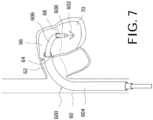
- FIG. 7illustrates an embodiment of a fixation device that can be adapted for use in systems in accordance with the disclosed subject matter.
- the fixation device, or clip, 1602includes a coupling member 1632 and a pair of opposed distal elements 1634, the distal elements 1634 being formed as elongate arms rotatably connected to the coupling member 1632.
- the engagement surfaces 1636 of the distal elements 1634have a cupped or concave shape to surface area in contact with tissue and to assist in grasping and holding valve leaflets when deployed.
- the transverse width across engagement surfaces 1636(which determines the width of tissue engaged) is at least about 2 mm, usually 3-10 mm, and preferably about 4-6 mm.
- the distal elements 1634are configured to engage a length of tissue of about 4-10 mm, and preferably about 6-8 mm along the longitudinal axis of the distal elements 1634.
- the distal elements 1634can include a plurality of openings to enhance grip and to promote tissue ingrowth following implantation.
- valve leafletsWhen deployed, valve leaflets are grasped between the distal elements 1634 and a set of proximal elements 1638, which are resiliently cantilevered from coupling member 1632.
- the proximal elements 1638are resiliently biased toward the distal elements 1634.
- Each of the proximal elements 1638is shaped and positioned to be at least partially recessed within the concavity of the corresponding distal element 1634 when no tissue is present.
- the proximal elements 1638include a plurality of openings 1640 and scalloped side edges 1642 to increase grip on tissue.
- the clip 1602also includes an actuation mechanism 1644 formed from two linking legs each rotatably joined with one of the distal elements 1634 and rotatably joined at an opposite end to a stud 1646.
- an actuation mechanism 1644formed from two linking legs each rotatably joined with one of the distal elements 1634 and rotatably joined at an opposite end to a stud 1646.
- the legs of the actuation mechanism 1644are rotated, which also rotates the distal elements 1634 between closed, open and inverted positions.
- immobilization of the stud 1646holds the legs of the actuation mechanism 1644 in place to lock the distal elements 1634 in a desired position.
- the clip 1602can engage the tissue to be approximated.
- the distal elements 1634are oriented to be perpendicular to the line of coaptation, and are then positioned so that the engagement surfaces 1636 contact the ventricular surface of the valve leaflets.
- the proximal elements 1638remain on the atrial side of the valve leaflets so that the leaflets can be grasped between the proximal elements 1638 and distal elements 1634.
- the proximal elements 1638are lowered toward the engagement surfaces 1636 (e.g., by releasing tension on attached control lines) so that the leaflets are held therebetween.
- the distal elements 1634can be rotatably moved toward a closed position, and the clip 1602 can be decoupled from a shaft and/or any other delivery mechanisms.
- tissue fixation clipsare further described in U.S. Patent 7,666,204 and U.S. Patent 7,563,267 .
- Systems of the disclosed subject matterhave demonstrated desired performance characteristics, including adequate configuration and flow area of the annular space such that pressure waves originating exterior of the distal end portion of the guide catheter can be transmitted through the annular space along the length of the guide catheter and can be monitored by the pressure sensor proximate the proximal end of the guide catheter.
- desired performance characteristicsincluding adequate configuration and flow area of the annular space such that pressure waves originating exterior of the distal end portion of the guide catheter can be transmitted through the annular space along the length of the guide catheter and can be monitored by the pressure sensor proximate the proximal end of the guide catheter.
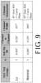
- FIG. 9depicts dimensions of the delivery systems tested.
- the Lo test groupincluded 5 systems with the dimensions shown.
- the inner diameter 801 of the distal end port, or “Soft Tip ID,”was measured as 0.205 inches for the five Lo samples tested.
- the "Channel to Channel” dimension 802was measured as 0.226 inches for the five Lo samples tested, which corresponds with a flow channel depth of 0.0105 inches.
- the flow channel width 803was measured as 0.057 inches for the five Lo samples tested.
- the inner diameter 801 of the distal end port, or “Soft Tip ID,”was measured as 0.206 inches for the five Nominal samples tested.
- the "Channel to Channel” dimension 802was measured as 0.229 inches for the five Nominal samples tested, which corresponds with a flow channel depth of 0.0115 inches.
- the flow channel width 803was measured as 0.060 inches for the five Nominal samples tested.
- the flow channels 806were offset circumferentially by about 45 degrees from the guide catheter bend reference plane for each of the samples tested in both the Nominal and Lo groups.
- a 5 Fr reference catheterwas tested with each test unit as a control. Reference catheters were inspected before use. If kinked or damaged, a new catheter was used. 5Fr diagnostic catheters are an acceptable control per current industry standards for invasive left atrial hemodynamic monitoring.
- a tolerance intervalalso referred to as a confidence and reliability interval
- a confidence and reliability intervalis a conservative choice for a coverage interval compared to a confidence interval. This is because it makes an inference on the proportion of individual values within the population at a specified confidence level, as opposed to making an inference on just the location of the average value.
- Data outputs from the testinginclude pressure profiles from the 5 Fr reference catheter and the tested guide catheter across five cardiac cycles for each test configuration /condition.
- Descriptive statisticsi.e. mean ⁇ standard deviation of the waveform maximum, mean, and minimum
- Max, Mean, and Min valuescan be clinically relevant values for assessment. The minimum value can be used to ensure the overall amplitude of the waveform is not dampened.
- the atrial pressure testing modelis comprised of three main components: a preload chamber, rigid atrial chamber, and pulsatile pump.
- the pre-load chamberserves as a fluid reservoir to passively fill the simulated atrium (LA) of heart and most importantly simulates pre-load pressures into LA from pulmonary flow.
- the rigid atrial chamberis 3-D printed to include several access points for secure entry of SGC device, reference catheter and endoscope.
- the atriumis connected to a pulsatile pump, which controls the stroke volume, flow rate, and output phase ratio.
- the results of the Shapiro-Wilk W testshow the P-values for SGC07-Nominal max, mean, and min groups are 0.051, 0.452, and 0.246, respectively. Since the P values are ⁇ 0.010, there is insufficient evidence to reject the assumption that the data were drawn from a normal distribution. Therefore, it is acceptable compare the one-sided upper tolerance limit at 95/95 confidence and reliability to the acceptance limit of 5 mmHg. All calculated upper tolerance limits are less than 5 mmHg.
- the results of the Shapiro-Wilk W testshow the P-values for SGC07-Low max, mean, and min groups are 0.026, 0.161, and 0.025, respectively. Since the P values are ⁇ 0.010, there is insufficient evidence to reject the assumption that the data were drawn from a normal distribution. Therefore, it is acceptable compare the one-sided upper tolerance limit at 95/95 confidence and reliability to the acceptance limit of 5 mmHg. All calculated upper tolerance limits are less than 5 mmHg.
- systems according to the disclosed subject matterdemonstrated adequate configuration and size to enable pressure monitoring capability as compared to a 5Fr reference catheter under the laboratory test conditions described above.
Landscapes
- Health & Medical Sciences (AREA)
- Life Sciences & Earth Sciences (AREA)
- Cardiology (AREA)
- General Health & Medical Sciences (AREA)
- Public Health (AREA)
- Biomedical Technology (AREA)
- Heart & Thoracic Surgery (AREA)
- Engineering & Computer Science (AREA)
- Veterinary Medicine (AREA)
- Animal Behavior & Ethology (AREA)
- Pathology (AREA)
- Physics & Mathematics (AREA)
- Biophysics (AREA)
- Medical Informatics (AREA)
- Molecular Biology (AREA)
- Surgery (AREA)
- Vascular Medicine (AREA)
- Physiology (AREA)
- Oral & Maxillofacial Surgery (AREA)
- Transplantation (AREA)
- Measuring Pulse, Heart Rate, Blood Pressure Or Blood Flow (AREA)
Description
- This application claims the benefit of
U.S. Provisional Application No. 62/906,581, filed September 26, 2019 - During cardiac procedures, blood pressure is often measured and monitored at different areas of the heart to aid in initial diagnosis, to confirm procedural safety, and to verify procedural efficacy. For example, in the context of a mitral valve repair or replacement procedure, right-atrial pressure, left-atrial pressure, and pressure gradients across the mitral valve can be measured during and after the procedure.
- Typically, such pressure monitoring is achieved through the use of a pressure wire or fractional flow reserve ("FFR") wire that is inserted into the targeted treatment area of the heart. For example, an operator can introduce a pressure wire into a pulmonary vein to monitor left atrial pressure during a mitral valve repair or replacement procedure. In some circumstances, indirect imaging-based methods are also used to calculate pressure.
- Although some degree of intra-procedural pressure monitoring is enabled through these methods, there remains a need for continued improvement. For example, the use of a pressure wire or FFR wire in conjunction with guidewires, catheters, and other components of the procedure can be cumbersome and can increase procedure time. Additionally, in procedures that involve crossing of the septum, monitoring pressure at the targeted area using conventional techniques can require a larger septal puncture, or a second puncture to provide access for a pressure wire to the targeted area.
- Accordingly, in many circumstances, the potential benefits of monitoring cardiac pressure intra-procedurally are negated and offset by the foregoing problems. International Application
WO2018/022919 describes intra-procedural cardiac pressure monitoring systems for delivering a pressure monitoring sensor to the heart using routing lumens or grooves in a delivery catheter. Such systems can eliminate the need for a second septal puncture to deliver the pressure sensor to the heart. However, there remains a continued need for alternative pressure measurement systems. - The subject matter disclosed herein is not limited to embodiments that solve any issues or that operate only in environments such as those described above. Rather, this background is only provided to illustrate one exemplary technology area where embodiments described herein can be practiced.
US 2019/167197 discloses delivery devices and interventional devices configured to enable monitoring of pressure and other hemodynamic properties before, during, and/or after a cardiac procedure. A guide catheter includes a routing lumen or a routing groove for routing a sensor wire to a desired location during a cardiac procedure. A guide catheter includes one or more pressure sensors positioned to provide desired pressure measurements when the guide catheter is deploying an interventional device. An interventional device may also include one or more associated sensors for providing hemodynamic information before, during, and/or after deployment.EP 1,208,867 discloses an endovascular device for partitioning the ascending aorta and a system for arresting the heart to facilitate the performance of procedures such as heart valve replacement or coronary artery bypass grafting without the need for a thoracotomy.- The extent of protection is defined by the scope of the claims.
- It should be noted that 1 inch (in) corresponds to 25.4 mm.
- The purpose and advantages of the disclosed subject matter will be set forth in and apparent from the description that follows, as well as will be learned by practice of the disclosed subject matter. For purpose of illustration and not limitation, the various embodiments described herein relate to interventional delivery systems configured for delivering an interventional device (such as, a valve repair or replacement device, annuloplasty ring, chord replacement or repair device, spacer device, occlusion device, suturing device, or other cardiac interventional device) to a targeted treatment area. The delivery systems are configured to enable the monitoring of hemodynamic properties before, during, and/or after deployment of the interventional device. Additional advantages of the disclosed subject matter will be realized and attained by the methods and systems particularly pointed out in the written description and claims hereof, as well as from the appended drawings.
- To achieve these and other advantages, and in accordance with the purpose of the disclosed subject matter, as embodied and broadly described, the disclosed subject matter includes a delivery system for a fixation device, the delivery system including a guide catheter with a proximal end portion having a proximal end port, a distal end portion having a distal end port, and an inner surface defining an inner lumen extending in fluid communication between the proximal end port and the distal end port. The system further includes a delivery catheter extending through the inner lumen of the guide catheter to define an annular space between an outer surface of the delivery catheter and the inner surface of the guide catheter. The system further includes a pressure sensor proximate the proximal end portion of the guide catheter in fluid communication with the annual space to monitor fluid pressure within the annular space. The distal end portion of the guide catheter includes a distal tip member having the distal end port defined therein; the distal tip member comprising a plurality flow passages in fluid communication between an exterior of the distal end portion of the guide catheter and the annular space, the plurality of flow passages comprising a number of flow channels defined in the distal tip member and spaced about a perimeter of the distal end port.
- In accordance with an aspect of the disclosed subject matter, the plurality of flow passages collectively can have a total flow area between the exterior of the distal end portion and the annular space of between about 0.0021 in2 and 0.0031 in2. Additionally, the delivery system can include a fixation device removably coupled to a distal end of the delivery catheter and configured for fixation to leaflets of a native valve.
- The number of flow channels can be spaced equally about the perimeter of the distal end port. For example, the number of flow channels can be four flow channels. For purpose of example and not limitation, each flow channel can have a width of about 0.056 to 0.062 inches. As embodied herein, each flow channel can have a width of about 0.059 inches. Furthermore, each flow channel can have a depth from the perimeter of the distal end port. For purpose of example and not limitation, the depth can be between about 0.009 to about 0.0125 inches. As embodied herein, each flow channel can have a depth of about 0.011 inches.
- The distal end port can have an inner diameter substantially equal to an outer diameter along a distal end portion of the delivery catheter. For purpose of example and not limitation, the inner diameter can be between about 0.204 and about 0.209 inches. As embodied herein, the inner diameter can be about 0.206 inches. The distal end portion of the guide catheter can include a distal tip member having the distal end port and the flow channels defined therein. The distal tip member can have a durometer hardness measurement of 40D up to 55D or greater. Additionally, or alternatively, the distal tip member can be made of a Pebax material.
- In accordance with another aspect, the guide catheter can be a steerable guide catheter. The steerable guide catheter can include a steering mechanism with a plurality of cables extending a length of the guide catheter. The steering mechanism can be adapted to bend the distal end portion of the guide catheter in at least one reference plane. Each flow channel can be offset circumferentially about the perimeter of the distal end port from the reference plane. For purpose of example, and as embodied herein, each flow channel can be offset circumferentially by about 45° from the reference plane.
- As embodied herein, the proximal end portion of the guide catheter can include a luer connector in fluid communication with the annular space. The pressure sensor can be removably connectable to the luer connector. The pressure sensor can be a pressure transducer. Furthermore, the proximal end portion can include a hemostasis valve to seal a proximal end of the annual space.
- Furthermore, the distal end portion of the guide catheter can include a braided reinforcement.
- It is to be understood that both the foregoing general description and the following detailed description are exemplary.
FIG. 1 is a perspective view of an exemplary delivery system in accordance with the disclosed subject matter;FIG. 2 is a schematic view of an exemplary guide catheter suitable for use in a delivery system in accordance with the disclosed subject matter;FIG. 3 is a partial detail view depicting various positions of the distal end portion of the guide catheter ofFIG. 2 ;FIG. 4A is an end view of the guide catheter ofFIG. 2 , depicting the arrangement of flow passages and cables;FIG. 4B is a partial cross-sectional view of the delivery system ofFIG. 1 , taken alongline 4B-4B, as depicted inFIG. 1 ;FIG. 5 is a partial detail view of a distal end portion of the guide catheter ofFIG. 2 .FIG. 6 is a partial detail view of a distal end portion of a guide catheter in accordance with another aspect of the disclosed subject matter;FIG. 7 illustrates a schematic view of a transfemoral approach for delivering an interventional device and/or performing an interventional procedure;FIG. 8 illustrates an exemplary fixation device suitable for use in a delivery system in accordance with the disclosed subject matter;FIG. 9 is a chart depicting measured characteristics of exemplary guide catheters tested with delivery systems in accordance with the disclosed subject matter.FIG. 10 is a block diagram of a laboratory testing model used to measure certain performance characteristics of delivery systems in accordance with the disclosed subject matter;FIGs. 11A and 11B are charts depicting statistical analysis data obtained during testing of exemplary delivery systems in accordance with the disclosed subject matter.- Reference will now be made in detail to the various exemplary embodiments of the disclosed subject matter, which are illustrated in the accompanying drawings. The structure and corresponding method of operation of the disclosed subject matter will be described in conjunction with the detailed description of the system.
- The disclosed subject matter is directed to devices, systems, and methods enabling intra-procedural monitoring of cardiac pressure and related hemodynamics. As embodied herein, pressure monitoring can be enabled before, during, and/or after a cardiac procedure. Although the embodiments described herein are directed to a mitral valve repair procedure for purpose of illustration and not limitation, it will be understood that the related principles and/or components can also be applied within the context of another cardiac procedure, such as a mitral valve replacement, tricuspid valve repair or replacement, chordae tendineae repair or replacement, septal defect repair, occlusion, leaflet modification, leaflet plication, or other cardiac procedure where the monitoring of blood pressure or other hemodynamic properties is desired.
- In addition, although reference is made to "intra-procedural" pressure monitoring, pre and/or post-procedural pressure monitoring also is contemplated.
- Further, although reference is made to various components for measuring blood pressure, it will be understood that such pressure monitoring can, alternatively or additionally, include blood flow monitoring and/or the monitoring of other hemodynamic properties. Accordingly, the terms "sensor," "sensor wire," "transducer," and the like, as user herein, typically refer to pressure-sensing devices, but in other embodiments, can additionally or alternatively refer to flow sensing devices and/or devices configured for measuring other hemodynamic properties. In addition, although various descriptions make reference to "sensor" in the singular, it will be understood that alternative embodiments include one or more sensor arrays having multiple different sensors arranged together as a sensor array unit.
- Delivery systems in accordance with the disclosed subject matter generally include a guide catheter with a proximal end portion having a proximal end port, a distal end portion having a distal end port, and an inner surface defining an inner lumen extending in fluid communication between the proximal end port and the distal end port. The system further includes a delivery catheter extending through the inner lumen of the guide catheter to define an annular space between an outer surface of the delivery catheter and the inner surface of the guide catheter. The system further includes a pressure sensor proximate the proximal end portion of the guide catheter in fluid communication with the annual space to monitor fluid pressure within the annular space. The distal end portion of the guide catheter includes a plurality flow passages in fluid communication between an exterior of the distal end portion of the guide catheter and the annular space. In accordance with an aspect of the disclosed subject matter, the plurality of flow passages can collectively have a total flow area between the exterior of the distal end portion and the annular space of between about 0.0021 in2 and 0.0031 in2. In accordance with another aspect of the disclosed subject matter, a fixation device can be removably coupled to a distal end of the delivery catheter and configured for fixation to leaflets of a native valve can be provided.
- The accompanying figures, where like reference numerals refer to identical or functionally similar elements throughout the separate views, serve to further illustrate various embodiments and to explain various principles and advantages all in accordance with the disclosed subject matter.
- For purpose of illustration, and not limitation, reference is made to the exemplary embodiment of a delivery system shown in
FIG. 1 . The illustrateddelivery system 100 can be configured as a multi-catheter guiding system for delivering aninterventional device 102 to a targeted treatment area (e.g., through transapical, transfemoral, or transthoracic introduction). By way of example, theinterventional device 102 can be a replacement valve (e.g., mitral, tricuspid, aortic, or pulmonary valve), tissue fixation device (e.g., valve clip), chordae tendineae (i.e., chord) replacement or repair device, annuloplasty ring, occluding device, septal defect repair device, spacer, suture device, or other interventional device suitable for use in a structural heart procedure. For purpose of illustration and not limitation, reference is made herein to a delivery system for a tissue fixation device. - The
delivery system 100 hasproximal end 120 and adistal end 122. Thesystem 100 includes aguide catheter 300 having aproximal end portion 301, and adistal end portion 302. As described further herein, theproximal end portion 301 includes aproximal end port 303 and thedistal end portion 302 includes adistal end port 304, and an inner lumen extends in fluid communication between theproximal end port 303 and thedistal end port 304. In accordance with another aspect of the disclosed subject matter, and as described further below, theguide catheter 300 can be a steerable guide catheter. - The
system 100 further includes adelivery catheter 104 extending through theinner lumen 128 of theguide catheter 300. For purpose of example, and as embodied herein, thedelivery catheter 104 can include asteerable sleeve 106 with aninner shaft 108 disposed therein, as described further herein. Thesteerable sleeve 106 can be positioned radially within theguide catheter 300, andinner shaft 108 can be positioned radially within thesleeve 106, as shown. Anannular space 124 is defined between anouter surface 127 of thedelivery catheter 104 and aninner surface 319 of theguide catheter 300. As embodied herein,outer surface 127 of the delivercatheter 108 can be an outer surface of thesteerable sleeve 106. Theinner shaft 108 can be translatable within thesteerable sleeve 106, and thesteerable sleeve 106 can be translatable within theguide catheter 300. - While the
system 100 is depicted with aguide catheter 300 and adelivery catheter 104 having asteerable sleeve 106 andinner shaft 108 disposed therein, those of skill in the art will recognize that delivery systems in accordance with the disclosed subject matter can have alternate configurations. For purpose of example and not limitation, delivery systems can include multiple guide catheters, such as an outer guide catheter and one or more inner guide catheters disposed therein. Alternatively, the delivery system can be a single integral component. - For purpose of example, and as described further below, a
fixation device 102 can be removably coupled to a distal end of the delivery catheter and configured for fixation to leaflets of a native valve. Manipulation of theguide catheter 300 and/orsleeve 106 can enable thefixation device 102 to be directed through a patient's vasculature to a targeted treatment area of the patient's heart. As embodied herein, angling of theguide catheter 300 and theinner sleeve 106 can be achieved using the guide catheter handle 309 and the sleeve handle 112 attached to the proximal ends of theguide catheter 300 and thesleeve 106, respectively. As shown, the guide catheter handle 309 is coupled to the proximal end of theguide catheter 300, and thesleeve handle 112 is coupled to the proximal end of thesleeve 106. Thesleeve 106 is inserted through the guide catheter handle 309 to position thesleeve 106 radially within theguide catheter 300. Theinner shaft 108 is inserted through the sleeve handle 112 to position theinner shaft 108 radially within thesleeve 106 and theguide catheter 300. As embodied herein, an inner shaft can be assembled within a sleeve to limit translation within the sleeve. For example, an inner shaft can have a larger profile than the sleeve at sections of the inner shaft proximal and/or distal to the sleeve according to the order of construction/assembly. - For purpose of illustration, and not limitation, reference is made to the exemplary embodiment of a
guide catheter 300 shown inFIGs. 2 and3 . Theguide catheter 300 includes aproximal end portion 301 having aproximal end port 303 and adistal end portion 302 having adistal end port 304. Aninner surface 319 of theguide catheter 300 defines an inner lumen extending in fluid communication between theproximal end port 303 and thedistal end port 304. Thedistal end portion 302 of theguide catheter 300 includes aplurality flow passages 205 as described further herein. - As embodied herein, guide
catheter 300 can have a generally tubular shape, and can be comprised of a material which provides hoop strength while maintaining flexibility and kink resistance, such as a braided laminated material. Such material can include stainless steel braided or coiled wire embedded in a polymer such as polyurethane, polyester, Pebax, Grilamid TR55, and AESNO to name a few. At least a length of theguide catheter 300 can include a braided reinforcement. For purpose of example and not limitation, a distal end portion of the guide catheter can include a braided reinforcement. To provide further support and hoop strength, a support coil can be disposed within the lumen of theguide catheter 300. - With reference to
FIG. 3 , guidecatheter 300 and/or thesleeve 106 can be a steerable guide catheter and can include steering mechanisms to position thedistal end 302 of theguide catheter 300 and/orsleeve 106 in desired directions. Theguide catheter 300 can include a steering mechanism having a plurality ofcables guide catheter 300 can include afirst cable 378 slidably disposed in a lumen within the wall of theguide catheter 300 and extending a length of the guide catheter to thedistal end portion 302. By applying tension to thecable 378 in the proximal direction, thedistal end 302 curves in the direction of thecable 378 as illustrated byarrow 382. Likewise, placement of asecond cable 380 along the opposite side of theguide catheter 300 will allow thedistal end 302 to be curved in the opposite direction, as illustrated byarrow 384, when tension is applied to thesecond cable 380. - Thus, the
opposed cables guide catheter 300 can enable thedistal end 302 to be steered or bent in opposite directions. As embodied herein, the steering mechanism can include one ormore steering knobs cables guide catheter 300 and/or thesleeve 106. This can provide a means of correcting or adjusting a curvature of theguide catheter 300 and/orsleeve 106 within one or more reference planes. For example, if tension is applied to one cable to create a curvature, the curvature can be lessened by applying tension to the diametrically opposite cable. The illustrated embodiment includes two opposing cables. Other embodiments can include a single cable, or can include more than two cables. In addition, cables and associated lumens can be placed in any arrangement, singly or in pairs, symmetrically or non-symmetrically, to enable desired curvature capabilities. Cables can be fixed at any location along the length of theguide catheter 300 by any suitable method, such as gluing, tying, soldering, and the like. When tension is applied to the cable, the curvature forms from the point of attachment of the cable toward the proximal direction. Typically, however, cables are attached near thedistal end 302 of theguide catheter 300. Additionally, or alternatively, one or more of theguide catheter 300 or thesleeve 106 can be precurved to provide a desired angling for properly traversing a patient's vasculature in the context of a particular procedural approach. - For example, precurvature or steering of the
guide catheter 300 can direct the distal end of theguide catheter 300 to form a first curve, while precurvature or steering of thesleeve 106 can direct the distal end of thesleeve 106 to form a second curve. In this manner, the first curve can differ from that of the second curve so that together the curves form a compound curve. For example, for a mitral valve procedure using a transfemoral approach, the primary curve can have a radius of curvature in the range of 0.8 to 1.0 inches and the secondary curve often has a radius of curvature in the range of 0.050 to 0.750 inches. Advancement of theinner shaft 108 through thesleeve 106 thereby guides theinner shaft 108 through the resulting compound curve, and enables thefixation device 102 to be delivered to the targeted treatment area in a desired orientation. Theinterventional device 102 can then be actuated, deployed, and/or released through manipulation of thedelivery handle 114. As embodied herein, a guide catheter can be configured with precurvature and/or steering functionality so as to accommodate transjugular delivery or other vascular delivery. Alternatively, curvature of both theguide catheter 300 and thesleeve 106 can be oriented in the same direction to provide an even higher angular curvature about a single axis. - The dimensions of the
guide catheter 300 can be selected based on the desired use and performance characteristics of theguide catheter 300. For example, smaller outer diameters of theguide catheter 300 can be desirable to facilitate navigation through a patient's vasculature. Additionally, the inner diameter of theguide catheter 300 can be selected, for example, to accommodate thedelivery catheter 104 andfixation device 102 within the inner lumen of the guide catheter. The inner diameter of the guide catheter can be varied along the length of the guide catheter. For example, and as described further herein, the distal end portion of the guide catheter can be tapered, and the distal end port can have a smaller inner diameter than an inner diameter of a proximal portion of the guide catheter. For purpose of example, and not limitation, the inner diameter of thedistal end port 304 of theguide catheter 300 can be between about 0.205 inches and 0.208 inches. As embodied herein, the inner diameter of thedistal end port 304 can be about 0.206 inches. The inner diameter of thedistal end port 304 can be selected such that thedistal end port 304 has an inner diameter substantially equal to an outer diameter of thedelivery catheter 104 along a distal end portion of thedelivery catheter 104. As embodied herein, thedistal end port 304 can have an inner diameter substantially equal to an outer diameter of thesteerable sleeve 106 of thedelivery catheter 104 along a distal end portion of thedelivery catheter 104. - In accordance with the disclosed subject matter, the
system 100 further includes apressure sensor 330 proximate theproximal end portion 301 of theguide catheter 300. Thepressure sensor 330 is in fluid communication with theannular space 124 to monitor fluid pressure within the annular space, as described further herein. The pressure sensor can be placed in fluid communication with theannular space 124 using any suitable means. For purpose of example, and as embodied herein, theproximal end portion 301 of theguide catheter 300 can include aluer connector 332 in fluid communication with the annular space. Thepressure sensor 330 can be removably connectable to theluer connector 332, for example, usingtubing 331. For purpose of example, the length oftubing 331 can be selected such that the pressure sensor can be positioned at the same height as the patient's heart. Additionally or alternatively, thepressure sensor 330 can be removably connected to theluer connector 332 withouttubing 331. A pressure offset can be applied if thepressure sensor 330 is positioned at a different vertical height from the patient's heart to account for changes in pressure due to gravitational forces. Thetubing 331 used can have a lumen cross sectional area greater than the minimum flow area of theannular space 124. - Those of skill in the art will recognize that various pressure sensors are known in the art. Any suitable pressure sensor can be used with the delivery systems described herein. For purpose of example, and as embodied herein, the pressure sensor can be a pressure transducer. As described further herein, a pressure sensor capable of detecting changes in pressure as small as about 5 mmHg can be selected. As described further herein, the
pressure sensor 330 proximate the proximal end portion of theguide catheter 300 can detect changes in pressure transmitted through theannular space 124 from exterior of thedistal end 302 of the guide catheter. - For purpose of example, and as embodied herein, the
proximal end portion 301 of theguide catheter 300 can include ahemostasis valve 148 to seal a proximal end of the annular space. Thehemostasis valve 148 can be configured to reduce the risk of air introduction and to prevent back bleeding during use of the system. As embodied herein, thehemostasis valve 148 can form a seal between theproximal end 301 of theguide catheter 300 and an outer surface of thedelivery catheter 104. - With reference to
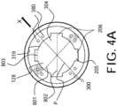
FIGs. 4A and4B , theguide catheter 300 includes a plurality offlow passages 205 in fluid communication between an exterior of thedistal end portion 302 of theguide catheter 300 and anannular space 124 defined between anouter surface 127 of thedelivery catheter 104 and aninner surface 319 of theguide catheter 300. In accordance with an aspect of the disclosed subject matter, the plurality offlow passages 205 can collectively have a total flow area between the exterior of thedistal end portion 302 and theannular space 124 of between about 0.0021 in2 and 0.0031 in2. For purpose of example, and as embodied herein, the flow passages can include fourflow channels 206 spaced about a perimeter of thedistal end port 304. Additionally, or alternatively, the plurality offlow passages 205 can include a number of flow openings defined through a wall of the guide catheter, as described further herein. - The configuration of the
flow passages 205 can be selected to provide the desired total flow area in communication with theannular space 124 of sufficient size to accurately monitor pressure exterior of the distal end portion, such as an atrial pressure, using a pressure sensor proximate the proximal end portion of the guide catheter, as described further herein. For example, and for purpose of measuring atrial pressure, it has been determined that a fluid column equivalent to that of a 5 Fr catheter is sufficient to obtain accurate atrial pressure measurements. SeeGaemperli, O., et al., (2011). Acute hemodynamic changes after percutaneous mitral valve repair: Relation to mid-term outcomes. Heart, 98(2), 126-132, doi: 10.1136/heartjnl-2011-300705. - The
flow passages 205 can have any suitable shape in end view, including an arcuate shape, substantially triangular shape, or square shape. For purpose of example, and as embodied herein, the flow passages can include fourflow channels 206, each having a generally rectangular shape in end view. The dimensions of theflow passages 206 can be selected to provide the desired total flow area, as noted above. For example, and with fourflow channels 206 forming the flow passages, each channel can have awidth 803 of between about 0.056 inches and 0.062 inches, and a depth measured from the perimeter of thedistal port 304 of between about 0.009 inches and 0.0125 inches. For purpose of example, and with reference toFIG. 4A , the depth of each flow channel can be calculated by subtracting the guide catheterinner diameter 801 from the channelto-channel dimension 802 and dividing the difference by two. As embodied herein, each flow channel can have awidth 803 of about 0.059 inches and a depth of about 0.011 inches. - As will be understood by those of skill in the art, the number of
flow passages 206, shape offlow passages 206, and dimensions of theflow passages 206 can be selected to achieve the desired total flow area. For example, as the number offlow passages 206 increases, the dimensions of eachrespective flow passage 206 can decrease such that the total flow area between the exterior of the distal end portion and the annular space is between about 0.0021 in2 and 0.0031 in2. - With reference to
FIG. 4A , the steering mechanism described above having a plurality ofcables 380 extending a length of theguide catheter 300 can be seen within the sidewall of theguide catheter 300. As described above, applying tension tocables 380 can cause the distal end portion ofguide catheter 300 to bend or curve in direction X within reference plane P. For purpose of example and not limitation, eachflow channel 206 can be offset circumferentially about the perimeter of thedistal end port 304 from the reference plane P. As embodied herein, each flow channel can be offset circumferentially by about 45 degrees from the reference plane P. The circumferential offset of theflow channels 206 can help maintain adequate flow area in the annular space during insertion and manipulation of the delivery system. - The
flow passages 205, includingflow channels 206, can be formed or incorporated into the wall of theguide catheter 300, such as by extrusion, or can be a separate layer positioned within theguide catheter 300. Furthermore, theflow passages 205 can extend the entire length of theguide catheter 300 or can extend along one or more portions of the length of the catheter. For purpose of example and as embodied herein, theflow passages 205 can extend along a length of the distal end portion of the guide catheter. - With reference to
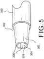
FIG. 5 , thedistal end 302 of theguide catheter 300 can be tapered. As embodied in the claimed invention, thedistal end 302 includes adistal tip member 307 having thedistal end port 304 and flowchannels 206 defined therein. As embodied herein, theflow channels 206 can run the length of thedistal tip member 307. Additionally or alternatively, theflow channels 206 can extend any suitable length from the exterior of thedistal end portion 302 proximally along the length of the distal end portion and/or along at least a portion of the intermediate length of theguide catheter 300. The length and location of theflow channels 206 along the length of the guide catheter can be selected to maintain sufficient flow area in communication with the annular space along the length of theguide catheter 300. - The material properties of the
distal tip member 307 can be selected based on the desired performance characteristics of the distal tip. For purpose of example and not limitation, thedistal tip member 307 can have a durometer hardness measurement of between about 40D and about 55D or greater. The distal tip can be made of any suitable material, including polyurethane, polyester, Pebax, Grilamid TR55, and AESNO, or various composite materials used in the construction of catheters. For purpose of example, and as embodied herein, the distal tip can be made of Pebax material having a durometer hardness measurement of 55D. - The material properties, including hardness, of the
distal tip member 307 and/ordistal end 302 can be selected to maintain the desired stiffness and other performance characteristics of thedistal tip member 307 and/ordistal end 302. For example, including flow channels in thedistal tip member 307 can reduce the stiffness of thedistal tip member 307 as compared to other distal tip members of similar dimensions and construction but without flow channels, as material is removed from the distal tip to define the flow channels therein. A stiffer material having a higher durometer hardness measurement can be used to compensate for the change in stiffness that can be caused by the use of flow channels in the distal tip. - In accordance with another aspect of the disclosed subject matter, and with reference to
FIG. 6 , the plurality offlow passages 205 can include a number offlow openings 403 defined through a wall of the guide catheter in fluid communication between the exterior of the distal end portion and the annular space.Flow openings 403 can be used in addition to, or as an alternative not claimed to, the flow channels described above. For purpose of example, and as embodied herein, theflow openings 403 can be generally circular in plan view. Theflow openings 403 can be defined along a desired length of theguide catheter 300. For example, and as embodied herein, the flow openings can be defined along a length of the guide catheter proximal to thedistal tip member 407. As described above, the shape, size, and number offlow openings 403 can be selected such that the total flow area between the exterior of the distal end portion and the annular space is between about 0.0021 in2 and 0.0031 in2. - Additional examples and details related to delivery devices for directing an interventional device to a targeted treatment area, including steering systems, fixation devices, valves, handles, and deployment mechanisms, are described in
U.S. Patent Number 7,666,204 ,U.S. Patent Number 7,563,267 ,U.S. Patent Application Publication No. 2015/0103804 andU.S. Patent Application Publication No. 2017/0100250 . - As described above, systems in accordance with the disclosed subject matter can be used in a variety of cardiac procedures, such as a mitral valve replacement, tricuspid valve repair or replacement, chordae tendineae repair or replacement, septal defect repair, occlusion, leaflet modification, leaflet plication, or other cardiac procedure where the monitoring of blood pressure or other hemodynamic properties is desired.
Figure 6 illustrates a transfemoral approach using adelivery system 600 in a procedure requiring access to the left side of the heart, such as a mitral valve repair or replacement procedure. As shown, aninterventional device 602 is delivered through the femoral vein by passing aninner shaft 608, to which theinterventional device 602 is coupled, through aguide catheter 604 and asleeve 606. Theinterventional device 602 is passed through theinferior vena cava 60, into theright atrium 62, through theinter-atrial septum 64 via a puncture, and into theleft atrium 66. When necessary or desired, theinterventional device 602 can then be directed across themitral annulus 68 and into theleft ventricle 70 via translation of theinner shaft 608. As shown, the steering functionality of theguide catheter 604 and/orsleeve 606, combined with the translatability of thesleeve 606 through theguide catheter 604 and the translatability of theinner shaft 608 through thesleeve 606, enables positioning of theinterventional device 602 at the targeted treatment area. Figure 7 illustrates an embodiment of a fixation device that can be adapted for use in systems in accordance with the disclosed subject matter. The fixation device, or clip, 1602 includes a coupling member 1632 and a pair of opposeddistal elements 1634, thedistal elements 1634 being formed as elongate arms rotatably connected to the coupling member 1632. The engagement surfaces 1636 of thedistal elements 1634 have a cupped or concave shape to surface area in contact with tissue and to assist in grasping and holding valve leaflets when deployed.- In an embodiment suitable for mitral valve repair, the transverse width across engagement surfaces 1636 (which determines the width of tissue engaged) is at least about 2 mm, usually 3-10 mm, and preferably about 4-6 mm. The
distal elements 1634 are configured to engage a length of tissue of about 4-10 mm, and preferably about 6-8 mm along the longitudinal axis of thedistal elements 1634. Thedistal elements 1634 can include a plurality of openings to enhance grip and to promote tissue ingrowth following implantation. - When deployed, valve leaflets are grasped between the
distal elements 1634 and a set ofproximal elements 1638, which are resiliently cantilevered from coupling member 1632. Theproximal elements 1638 are resiliently biased toward thedistal elements 1634. Each of theproximal elements 1638 is shaped and positioned to be at least partially recessed within the concavity of the correspondingdistal element 1634 when no tissue is present. Theproximal elements 1638 include a plurality ofopenings 1640 and scallopedside edges 1642 to increase grip on tissue. - The
clip 1602 also includes anactuation mechanism 1644 formed from two linking legs each rotatably joined with one of thedistal elements 1634 and rotatably joined at an opposite end to astud 1646. As thestud 1646 is moved axially, the legs of theactuation mechanism 1644 are rotated, which also rotates thedistal elements 1634 between closed, open and inverted positions. Likewise, immobilization of thestud 1646 holds the legs of theactuation mechanism 1644 in place to lock thedistal elements 1634 in a desired position. - In the open position, the
clip 1602 can engage the tissue to be approximated. During deployment in a mitral valve repair procedure, thedistal elements 1634 are oriented to be perpendicular to the line of coaptation, and are then positioned so that theengagement surfaces 1636 contact the ventricular surface of the valve leaflets. Theproximal elements 1638 remain on the atrial side of the valve leaflets so that the leaflets can be grasped between theproximal elements 1638 anddistal elements 1634. Once theclip 1602 has been properly positioned, theproximal elements 1638 are lowered toward the engagement surfaces 1636 (e.g., by releasing tension on attached control lines) so that the leaflets are held therebetween. - After the leaflets have been captured between the
proximal elements 1638 anddistal elements 1634 in a desired arrangement, thedistal elements 1634 can be rotatably moved toward a closed position, and theclip 1602 can be decoupled from a shaft and/or any other delivery mechanisms. Embodiments of tissue fixation clips are further described inU.S. Patent 7,666,204 andU.S. Patent 7,563,267 . - Systems of the disclosed subject matter have demonstrated desired performance characteristics, including adequate configuration and flow area of the annular space such that pressure waves originating exterior of the distal end portion of the guide catheter can be transmitted through the annular space along the length of the guide catheter and can be monitored by the pressure sensor proximate the proximal end of the guide catheter. For purpose of understanding and not limitation, data is provided to demonstrate various operational characteristics achieved by the systems disclosed herein. For purpose of understanding, laboratory measurements were collected to demonstrate the performance of systems in accordance with the disclosed subject matter under laboratory conditions, as described below.
FIG. 9 depicts dimensions of the delivery systems tested. The Lo test group included 5 systems with the dimensions shown. Theinner diameter 801 of the distal end port, or "Soft Tip ID," was measured as 0.205 inches for the five Lo samples tested. The "Channel to Channel"dimension 802 was measured as 0.226 inches for the five Lo samples tested, which corresponds with a flow channel depth of 0.0105 inches. Theflow channel width 803 was measured as 0.057 inches for the five Lo samples tested.- Likewise, the
inner diameter 801 of the distal end port, or "Soft Tip ID," was measured as 0.206 inches for the five Nominal samples tested. The "Channel to Channel"dimension 802 was measured as 0.229 inches for the five Nominal samples tested, which corresponds with a flow channel depth of 0.0115 inches. Theflow channel width 803 was measured as 0.060 inches for the five Nominal samples tested. - The flow channels 806 were offset circumferentially by about 45 degrees from the guide catheter bend reference plane for each of the samples tested in both the Nominal and Lo groups.
- A 5 Fr reference catheter was tested with each test unit as a control. Reference catheters were inspected before use. If kinked or damaged, a new catheter was used. 5Fr diagnostic catheters are an acceptable control per current industry standards for invasive left atrial hemodynamic monitoring.
- Five sample units per group were tested under three test conditions, simulating 60 BPM, 30 BPM, and 100 BPM, respectively. Thus, each test group included a total of 15 data points used for statistical analysis. Tolerance interval analysis was used, and the one-sided upper tolerance limit was calculated and compared to an acceptance limit. The use of a tolerance interval (also referred to as a confidence and reliability interval) is a conservative choice for a coverage interval compared to a confidence interval. This is because it makes an inference on the proportion of individual values within the population at a specified confidence level, as opposed to making an inference on just the location of the average value.
- Data outputs from the testing include pressure profiles from the 5 Fr reference catheter and the tested guide catheter across five cardiac cycles for each test configuration /condition. Descriptive statistics (i.e. mean ± standard deviation of the waveform maximum, mean, and minimum) from the average of the five cardiac cycles was calculated for both the reference catheter and tested guide catheter. Max, Mean, and Min values can be clinically relevant values for assessment. The minimum value can be used to ensure the overall amplitude of the waveform is not dampened.
- Test Model: With reference to
FIG. 10 , the atrial pressure testing model is comprised of three main components: a preload chamber, rigid atrial chamber, and pulsatile pump. The pre-load chamber serves as a fluid reservoir to passively fill the simulated atrium (LA) of heart and most importantly simulates pre-load pressures into LA from pulmonary flow. The rigid atrial chamber is 3-D printed to include several access points for secure entry of SGC device, reference catheter and endoscope. the atrium is connected to a pulsatile pump, which controls the stroke volume, flow rate, and output phase ratio. - To ensure the test model produced waveforms appropriate for assessment of LAP monitoring devices, pressure waveforms from the model were compared to human LAP waveforms. Waveforms were downloaded Fast Fourier transform (FFT) analysis was conducted to break down the pressure signals, as a function of time, into the frequency domain such that the two signals could be compared in a similar format. The analysis resulted in the model producing waveforms of equal frequency to clinical data; therefore, the afore described model is appropriate for use.
- Results: Under all test conditions, the LAP (max, mean, and min values) measured by the Nominal and Lo samples are < 5 mmHg of the LAP measured by the reference catheter.
- With reference to
FIG. 11A , the results of the Shapiro-Wilk W test show the P-values for SGC07-Nominal max, mean, and min groups are 0.051, 0.452, and 0.246, respectively. Since the P values are ≥ 0.010, there is insufficient evidence to reject the assumption that the data were drawn from a normal distribution. Therefore, it is acceptable compare the one-sided upper tolerance limit at 95/95 confidence and reliability to the acceptance limit of 5 mmHg. All calculated upper tolerance limits are less than 5 mmHg. - With reference to
FIG. 11B , the results of the Shapiro-Wilk W test show the P-values for SGC07-Low max, mean, and min groups are 0.026, 0.161, and 0.025, respectively. Since the P values are ≥ 0.010, there is insufficient evidence to reject the assumption that the data were drawn from a normal distribution. Therefore, it is acceptable compare the one-sided upper tolerance limit at 95/95 confidence and reliability to the acceptance limit of 5 mmHg. All calculated upper tolerance limits are less than 5 mmHg. - Accordingly, systems according to the disclosed subject matter demonstrated adequate configuration and size to enable pressure monitoring capability as compared to a 5Fr reference catheter under the laboratory test conditions described above.
- In addition to the specific embodiments claimed below, the disclosed subject matter is also directed to other embodiments having any other possible combination of the dependent features claimed below and those disclosed above. As such, the particular features presented in the dependent claims and disclosed above can be combined with each other in other manners within the scope of the disclosed subject matter such that the disclosed subject matter should be recognized as also specifically directed to other embodiments having any other possible combinations. Thus, the foregoing description of specific embodiments of the disclosed subject matter has been presented for purposes of illustration and description. It is not intended to be exhaustive or to limit the disclosed subject matter to those embodiments disclosed.
- It will be apparent to those skilled in the art that various modifications and variations can be made in the system of the disclosed subject matter. The extent of protection is defined by the scope of the claims.
Claims (15)
- A delivery system (100) for a fixation device, comprising:a guide catheter (300) comprising a proximal end portion (301) having a proximal end port (303), a distal end portion (302) having a distal end port (304), and an inner surface defining an inner lumen (128) extending in fluid communication between the proximal end port and the distal end port;a delivery catheter (104) extending through the inner lumen (128) of the guide catheter (300) to define an annular space (124) between an outer surface (127) of the delivery catheter (104) and the inner surface (319) of the guide catheter (300); anda pressure sensor (330) proximate the proximal end portion (301) of the guide catheter (300) in fluid communication with the annular space (124) to monitor fluid pressure within the annular space (124),wherein the distal end portion (302) of the guide catheter includes a distal tip member (307) having the distal end port (304) defined therein; the system ischaracterized in that the distal tip member (307) comprises a plurality flow passages (205) in fluid communication between an exterior of the distal end portion (302) of the guide catheter (300) and the annular space(124), the plurality of flow passages (205) comprising a number of flow channels (206) defined in the distal tip member (307) and spaced about a perimeter of the distal end port (304).
- The delivery system of claim 1, wherein the plurality of flow passages (205) collectively have a total flow area between the exterior of the distal end portion (302) and the annular space (124) of between about 0.014 cm2 and 0.020 cm2.
- The delivery system of claim 1, further comprising a fixation device (102) emovably coupled to a distal end of the delivery catheter (104) and configured for fixation to leaflets of a native valve.
- The delivery system of claim 1, wherein the number of flow channels (205) are spaced equally about the perimeter of the distal end port (304).
- The delivery system of claim 1, wherein the number of flow channels (205) comprise four flow channels.
- The delivery system of claim 1, wherein each flow channel (205) has a width of between about 0.14 cm and about 0.16 cm or wherein each flow channel (205) has a depth from the perimeter of the distal end port (304) of between about 0.0229 cm and about 0.0318 cm.
- The delivery system of claim 1, wherein the distal end port (304) has an inner diameter substantially equal to an outer diameter along a distal end portion (302) of the delivery catheter, optionally wherein the inner diameter is between about 0.518 cm and about 0.530 cm.
- The delivery system of claim 1 , wherein the distal tip member (307) has durometer hardness measurement of 55D, optionally wherein the distal tip member (307) is made of a Pebax material.
- The delivery system of claim 1, wherein the guide catheter (300) is a steerable guide catheter comprising a steering mechanism including a plurality of cables extending a length of the guide catheter, the steering mechanism adapted to bend the distal end portion of the guide catheter in at least one reference plane.
- The delivery system of claim 9, wherein each flow channel (205) is offset circumferentially about the perimeter of the distal end port (304) from the reference plane.
- The delivery system of claim 10, wherein each flow channel (205) is offset circumferentially by about 45° from the reference plane.
- The delivery system of claim 1, wherein the proximal end portion (301) of the guide catheter (300) further comprises a luer connector in fluid communication with the annular space, optionally wherein the pressure sensor (330) is removably connectable to the luer connector, optionally wherein the pressure sensor is a pressure transducer.
- The delivery system of claim 1, wherein the proximal end portion (301) further comprises a hemostasis valve to seal a proximal end of the annual space.
- The delivery system of claim 1, wherein the plurality of flow passages (205) further comprise a number of flow openings (403) defined through a wall of the guide catheter (300) in fluid communication between the exterior of the distal end portion and the annular space (124).
- The delivery system of claim 1, wherein the distal end portion (302) of the guide catheter (300) comprises a braided reinforcement.
Applications Claiming Priority (2)
| Application Number | Priority Date | Filing Date | Title |
|---|---|---|---|
| US201962906581P | 2019-09-26 | 2019-09-26 | |
| PCT/US2020/052646WO2021062103A1 (en) | 2019-09-26 | 2020-09-25 | Systems for intra-procedural cardiac pressure monitoring |
Publications (2)
| Publication Number | Publication Date |
|---|---|
| EP4033970A1 EP4033970A1 (en) | 2022-08-03 |
| EP4033970B1true EP4033970B1 (en) | 2024-11-20 |
Family
ID=72812002
Family Applications (1)
| Application Number | Title | Priority Date | Filing Date |
|---|---|---|---|
| EP20789377.7AActiveEP4033970B1 (en) | 2019-09-26 | 2020-09-25 | Systems for intra-procedural cardiac pressure monitoring |
Country Status (3)
| Country | Link |
|---|---|
| US (1) | US11707228B2 (en) |
| EP (1) | EP4033970B1 (en) |
| WO (1) | WO2021062103A1 (en) |
Families Citing this family (3)
| Publication number | Priority date | Publication date | Assignee | Title |
|---|---|---|---|---|
| EP4308042A1 (en) | 2021-03-19 | 2024-01-24 | Evalve, Inc. | Systems for tissue grasping and assessment |
| WO2023283368A1 (en)* | 2021-07-08 | 2023-01-12 | Evalve, Inc. | Valve repair clip with automatic locking mechanism activation |
| WO2025014589A1 (en)* | 2023-07-13 | 2025-01-16 | Becton, Dickinson And Company | Catheter system having a fluid chamber proximate a pressure transducer |
Family Cites Families (192)
| Publication number | Priority date | Publication date | Assignee | Title |
|---|---|---|---|---|
| US3378010A (en) | 1965-07-28 | 1968-04-16 | Coldling | Surgical clip with means for releasing the clamping pressure |
| US3874388A (en) | 1973-02-12 | 1975-04-01 | Ochsner Med Found Alton | Shunt defect closure system |
| FR2306671A1 (en) | 1975-04-11 | 1976-11-05 | Rhone Poulenc Ind | VALVULAR IMPLANT |
| US4340091A (en) | 1975-05-07 | 1982-07-20 | Albany International Corp. | Elastomeric sheet materials for heart valve and other prosthetic implants |
| US4007743A (en) | 1975-10-20 | 1977-02-15 | American Hospital Supply Corporation | Opening mechanism for umbrella-like intravascular shunt defect closure device |
| US4327736A (en) | 1979-11-20 | 1982-05-04 | Kanji Inoue | Balloon catheter |
| US4657024A (en) | 1980-02-04 | 1987-04-14 | Teleflex Incorporated | Medical-surgical catheter |
| US4809695A (en) | 1981-10-21 | 1989-03-07 | Owen M. Gwathmey | Suturing assembly and method |
| US4693248A (en) | 1983-06-20 | 1987-09-15 | Ethicon, Inc. | Two-piece tissue fastener with deformable retaining receiver |
| US4716886A (en) | 1986-05-01 | 1988-01-05 | Norman Schulman | Umbilical cord clamp and cutters |
| US5125895A (en) | 1986-07-22 | 1992-06-30 | Medtronic Versaflex, Inc. | Steerable catheter |
| US5478353A (en) | 1987-05-14 | 1995-12-26 | Yoon; Inbae | Suture tie device system and method for suturing anatomical tissue proximate an opening |
| US5542949A (en) | 1987-05-14 | 1996-08-06 | Yoon; Inbae | Multifunctional clip applier instrument |
| US4795458A (en) | 1987-07-02 | 1989-01-03 | Regan Barrie F | Stent for use following balloon angioplasty |
| US5002562A (en) | 1988-06-03 | 1991-03-26 | Oberlander Michael A | Surgical clip |
| US5069679A (en) | 1989-02-16 | 1991-12-03 | Taheri Syde A | Method and apparatus for removing venous valves |
| US4930674A (en) | 1989-02-24 | 1990-06-05 | Abiomed, Inc. | Surgical stapler |
| US5092872A (en) | 1989-07-28 | 1992-03-03 | Jacob Segalowitz | Valvulotome catheter |
| ATE107150T1 (en) | 1990-04-02 | 1994-07-15 | Kanji Inoue | DEVICE FOR CLOSING A SHUTTLE OPENING BY A NON-OPERATIONAL METHOD. |
| US5098440A (en) | 1990-08-14 | 1992-03-24 | Cordis Corporation | Object retrieval method and apparatus |
| US5389102A (en) | 1990-09-13 | 1995-02-14 | United States Surgical Corporation | Apparatus and method for subcuticular stapling of body tissue |
| US5611794A (en) | 1990-10-11 | 1997-03-18 | Lasersurge, Inc. | Clamp for approximating tissue sections |
| US5222963A (en) | 1991-01-17 | 1993-06-29 | Ethicon, Inc. | Pull-through circular anastomosic intraluminal stapler with absorbable fastener means |
| US5163955A (en) | 1991-01-24 | 1992-11-17 | Autogenics | Rapid assembly, concentric mating stent, tissue heart valve with enhanced clamping and tissue alignment |
| US5330501A (en) | 1991-05-30 | 1994-07-19 | United States Surgical Corporation | Tissue gripping device for use with a cannula and a cannula incorporating the device |
| US5147370A (en) | 1991-06-12 | 1992-09-15 | Mcnamara Thomas O | Nitinol stent for hollow body conduits |
| GR920100358A (en) | 1991-08-23 | 1993-06-07 | Ethicon Inc | Surgical anastomosis stapling instrument. |
| EP0541063B1 (en) | 1991-11-05 | 1998-09-02 | The Children's Medical Center Corporation | Improved occluder for repair of cardiac and vascular defects |
| US5363861A (en) | 1991-11-08 | 1994-11-15 | Ep Technologies, Inc. | Electrode tip assembly with variable resistance to bending |
| CA2128338C (en) | 1992-01-21 | 2004-10-12 | Gladwin S. Das | Septal defect closure device |
| US5327905A (en) | 1992-02-14 | 1994-07-12 | Boaz Avitall | Biplanar deflectable catheter for arrhythmogenic tissue ablation |
| US5782239A (en) | 1992-06-30 | 1998-07-21 | Cordis Webster, Inc. | Unique electrode configurations for cardiovascular electrode catheter with built-in deflection method and central puller wire |
| US6048351A (en) | 1992-09-04 | 2000-04-11 | Scimed Life Systems, Inc. | Transvaginal suturing system |
| US5342373A (en) | 1992-09-14 | 1994-08-30 | Ethicon, Inc. | Sterile clips and instrument for their placement |
| US5601224A (en) | 1992-10-09 | 1997-02-11 | Ethicon, Inc. | Surgical instrument |
| US5814097A (en) | 1992-12-03 | 1998-09-29 | Heartport, Inc. | Devices and methods for intracardiac procedures |
| US5403326A (en) | 1993-02-01 | 1995-04-04 | The Regents Of The University Of California | Method for performing a gastric wrap of the esophagus for use in the treatment of esophageal reflux |
| US5797960A (en) | 1993-02-22 | 1998-08-25 | Stevens; John H. | Method and apparatus for thoracoscopic intracardiac procedures |
| JPH08502438A (en) | 1993-02-22 | 1996-03-19 | ヴァリーラブ・インコーポレーテッド | Laparoscopic distraction tension retractor device and method |
| US6346074B1 (en) | 1993-02-22 | 2002-02-12 | Heartport, Inc. | Devices for less invasive intracardiac interventions |
| US5389077A (en) | 1993-03-03 | 1995-02-14 | Uresil Corporation | Minimally invasive body cavity penetrating instruments |
| US5636634A (en) | 1993-03-16 | 1997-06-10 | Ep Technologies, Inc. | Systems using guide sheaths for introducing, deploying, and stabilizing cardiac mapping and ablation probes |
| NL9300572A (en) | 1993-03-31 | 1994-10-17 | Cordis Europ | Method for manufacturing an extrusion profile with length-varying properties and catheter manufactured therewith. |
| US5456400A (en) | 1993-04-22 | 1995-10-10 | United States Surgical Corporation | Apparatus and clip for fastening body tissue |
| FR2708458B1 (en) | 1993-08-03 | 1995-09-15 | Seguin Jacques | Prosthetic ring for cardiac surgery. |
| US5450860A (en) | 1993-08-31 | 1995-09-19 | W. L. Gore & Associates, Inc. | Device for tissue repair and method for employing same |
| CA2171097A1 (en) | 1993-09-17 | 1995-03-30 | Philip C. Evard | Endovascular system for arresting the heart |
| US5607462A (en) | 1993-09-24 | 1997-03-04 | Cardiac Pathways Corporation | Catheter assembly, catheter and multi-catheter introducer for use therewith |
| US5452837A (en) | 1994-01-21 | 1995-09-26 | Ethicon Endo-Surgery, Inc. | Surgical stapler with tissue gripping ridge |
| US5609598A (en) | 1994-12-30 | 1997-03-11 | Vnus Medical Technologies, Inc. | Method and apparatus for minimally invasive treatment of chronic venous insufficiency |
| US5976159A (en) | 1995-02-24 | 1999-11-02 | Heartport, Inc. | Surgical clips and methods for tissue approximation |
| US5695504A (en) | 1995-02-24 | 1997-12-09 | Heartport, Inc. | Devices and methods for performing a vascular anastomosis |
| US5695505A (en) | 1995-03-09 | 1997-12-09 | Yoon; Inbae | Multifunctional spring clips and cartridges and applicators therefor |
| US5562678A (en) | 1995-06-02 | 1996-10-08 | Cook Pacemaker Corporation | Needle's eye snare |
| US5716417A (en) | 1995-06-07 | 1998-02-10 | St. Jude Medical, Inc. | Integral supporting structure for bioprosthetic heart valve |
| US6117144A (en) | 1995-08-24 | 2000-09-12 | Sutura, Inc. | Suturing device and method for sealing an opening in a blood vessel or other biological structure |
| US6015417A (en) | 1996-01-25 | 2000-01-18 | Reynolds, Jr.; Walker | Surgical fastener |
| US5860992A (en) | 1996-01-31 | 1999-01-19 | Heartport, Inc. | Endoscopic suturing devices and methods |
| US6182664B1 (en) | 1996-02-19 | 2001-02-06 | Edwards Lifesciences Corporation | Minimally invasive cardiac valve surgery procedure |
| US5843178A (en) | 1996-06-20 | 1998-12-01 | St. Jude Medical, Inc. | Suture guard for annuloplasty ring |
| US5855601A (en) | 1996-06-21 | 1999-01-05 | The Trustees Of Columbia University In The City Of New York | Artificial heart valve and method and device for implanting the same |
| WO1998007375A1 (en) | 1996-08-22 | 1998-02-26 | The Trustees Of Columbia University | Endovascular flexible stapling device |
| US5741297A (en) | 1996-08-28 | 1998-04-21 | Simon; Morris | Daisy occluder and method for septal defect repair |
| US5713911A (en) | 1996-10-03 | 1998-02-03 | United States Surgical Corporation | Surgical clip |
| US5755778A (en) | 1996-10-16 | 1998-05-26 | Nitinol Medical Technologies, Inc. | Anastomosis device |
| AU734856B2 (en) | 1996-11-27 | 2001-06-21 | Cook Medical Technologies Llc | Radio frequency dilator sheath |
| US6332880B1 (en) | 1996-12-19 | 2001-12-25 | Ep Technologies, Inc. | Loop structures for supporting multiple electrode elements |
| EP0850607A1 (en) | 1996-12-31 | 1998-07-01 | Cordis Corporation | Valve prosthesis for implantation in body channels |
| US6149658A (en) | 1997-01-09 | 2000-11-21 | Coalescent Surgical, Inc. | Sutured staple surgical fasteners, instruments and methods for minimally invasive vascular and endoscopic surgery |
| EP2133030A1 (en) | 1997-06-27 | 2009-12-16 | The Trustees of Columbia University of the City of New York | Method and apparatus for circulatory valve repair |
| IL121316A (en) | 1997-07-15 | 2001-07-24 | Litana Ltd | Implantable medical device of shape memory alloy |
| WO1999007354A2 (en) | 1997-08-08 | 1999-02-18 | Duke University | Compositions, apparatus and methods for facilitating surgical procedures |
| FR2768324B1 (en) | 1997-09-12 | 1999-12-10 | Jacques Seguin | SURGICAL INSTRUMENT FOR PERCUTANEOUSLY FIXING TWO AREAS OF SOFT TISSUE, NORMALLY MUTUALLY REMOTE, TO ONE ANOTHER |
| FR2768325B1 (en) | 1997-09-16 | 1999-11-19 | Instr Medecine Veterinaire | CATHETER FOR ARTIFICIAL INSEMINATION OF BIRDS, ESPECIALLY TURKEYS, AND METHOD FOR PRODUCING SUCH A CATHETER |
| AU9669898A (en) | 1997-09-26 | 1999-04-12 | Cardeon Corporation | Multi-function aortic catheterization and bumper instrument |
| US6120496A (en) | 1998-05-05 | 2000-09-19 | Scimed Life Systems, Inc. | Surgical method and apparatus for positioning a diagnostic or therapeutic element within the body and coupling device for use with same |
| US6200315B1 (en) | 1997-12-18 | 2001-03-13 | Medtronic, Inc. | Left atrium ablation catheter |
| US6193734B1 (en) | 1998-01-23 | 2001-02-27 | Heartport, Inc. | System for performing vascular anastomoses |
| US6599311B1 (en) | 1998-06-05 | 2003-07-29 | Broncus Technologies, Inc. | Method and assembly for lung volume reduction |
| US7569062B1 (en) | 1998-07-15 | 2009-08-04 | St. Jude Medical, Inc. | Mitral and tricuspid valve repair |
| US6165183A (en) | 1998-07-15 | 2000-12-26 | St. Jude Medical, Inc. | Mitral and tricuspid valve repair |
| US7972323B1 (en) | 1998-10-02 | 2011-07-05 | Boston Scientific Scimed, Inc. | Steerable device for introducing diagnostic and therapeutic apparatus into the body |
| US6544215B1 (en) | 1998-10-02 | 2003-04-08 | Scimed Life Systems, Inc. | Steerable device for introducing diagnostic and therapeutic apparatus into the body |
| US6217528B1 (en) | 1999-02-11 | 2001-04-17 | Scimed Life Systems, Inc. | Loop structure having improved tissue contact capability |
| US6064600A (en) | 1999-03-01 | 2000-05-16 | Micron Technology, Inc. | Methods and apparatus for reading memory device register data |
| US8118822B2 (en) | 1999-03-01 | 2012-02-21 | Medtronic, Inc. | Bridge clip tissue connector apparatus and methods |
| US7811296B2 (en) | 1999-04-09 | 2010-10-12 | Evalve, Inc. | Fixation devices for variation in engagement of tissue |
| US7226467B2 (en) | 1999-04-09 | 2007-06-05 | Evalve, Inc. | Fixation device delivery catheter, systems and methods of use |
| US6752813B2 (en) | 1999-04-09 | 2004-06-22 | Evalve, Inc. | Methods and devices for capturing and fixing leaflets in valve repair |
| US8216256B2 (en) | 1999-04-09 | 2012-07-10 | Evalve, Inc. | Detachment mechanism for implantable fixation devices |
| AU770243B2 (en) | 1999-04-09 | 2004-02-19 | Evalve, Inc. | Methods and apparatus for cardiac valve repair |
| US10327743B2 (en) | 1999-04-09 | 2019-06-25 | Evalve, Inc. | Device and methods for endoscopic annuloplasty |
| US20040044350A1 (en) | 1999-04-09 | 2004-03-04 | Evalve, Inc. | Steerable access sheath and methods of use |
| AU5884400A (en) | 1999-06-25 | 2001-01-31 | Vahid Saadat | Apparatus and methods for treating tissue |
| US6626899B2 (en) | 1999-06-25 | 2003-09-30 | Nidus Medical, Llc | Apparatus and methods for treating tissue |
| US6231561B1 (en) | 1999-09-20 | 2001-05-15 | Appriva Medical, Inc. | Method and apparatus for closing a body lumen |
| US6312447B1 (en) | 1999-10-13 | 2001-11-06 | The General Hospital Corporation | Devices and methods for percutaneous mitral valve repair |
| US6626930B1 (en) | 1999-10-21 | 2003-09-30 | Edwards Lifesciences Corporation | Minimally invasive mitral valve repair method and apparatus |
| US6551303B1 (en) | 1999-10-27 | 2003-04-22 | Atritech, Inc. | Barrier device for ostium of left atrial appendage |
| US6926730B1 (en) | 2000-10-10 | 2005-08-09 | Medtronic, Inc. | Minimally invasive valve repair procedure and apparatus |
| US6797002B2 (en) | 2000-02-02 | 2004-09-28 | Paul A. Spence | Heart valve repair apparatus and methods |
| US6419696B1 (en) | 2000-07-06 | 2002-07-16 | Paul A. Spence | Annuloplasty devices and related heart valve repair methods |
| SE0002878D0 (en) | 2000-08-11 | 2000-08-11 | Kimblad Ola | Device and method of treatment of atrioventricular regurgitation |
| US20020107531A1 (en) | 2001-02-06 | 2002-08-08 | Schreck Stefan G. | Method and system for tissue repair using dual catheters |
| WO2002078576A2 (en) | 2001-03-29 | 2002-10-10 | Viacor, Inc. | Method and apparatus for improving mitral valve function |
| US6837867B2 (en) | 2001-04-30 | 2005-01-04 | Biosense Webster, Inc. | Steerable catheter with reinforced tip |
| US7338514B2 (en) | 2001-06-01 | 2008-03-04 | St. Jude Medical, Cardiology Division, Inc. | Closure devices, related delivery methods and tools, and related methods of use |
| EP1432369B1 (en) | 2001-08-31 | 2008-02-27 | Mitral Interventions | Apparatus for valve repair |
| DE60229416D1 (en)* | 2001-10-25 | 2008-11-27 | Univ Emory | Catheter for modified perfusion |
| US6575971B2 (en) | 2001-11-15 | 2003-06-10 | Quantum Cor, Inc. | Cardiac valve leaflet stapler device and methods thereof |
| US6978176B2 (en) | 2001-12-08 | 2005-12-20 | Lattouf Omar M | Treatment for patient with congestive heart failure |
| US7048754B2 (en) | 2002-03-01 | 2006-05-23 | Evalve, Inc. | Suture fasteners and methods of use |
| US6855137B2 (en) | 2002-03-07 | 2005-02-15 | Visionary Biomedical, Inc. | Catheter shaft with coextruded stiffener |
| US7101395B2 (en) | 2002-06-12 | 2006-09-05 | Mitral Interventions, Inc. | Method and apparatus for tissue connection |
| US20040034365A1 (en) | 2002-08-16 | 2004-02-19 | Lentz David J. | Catheter having articulation system |
| JP4774048B2 (en) | 2004-05-14 | 2011-09-14 | エヴァルヴ インコーポレイテッド | Locking mechanism of fixing device engaged with tissue and tissue engaging method |
| US7556632B2 (en) | 2004-07-09 | 2009-07-07 | Reza Zadno | Device and method for repairing tissue |
| WO2006037073A2 (en) | 2004-09-27 | 2006-04-06 | Evalve, Inc. | Methods and devices for tissue grasping and assessment |
| US8277386B2 (en) | 2004-09-27 | 2012-10-02 | Volcano Corporation | Combination sensor guidewire and methods of use |
| CA2597066C (en) | 2005-02-07 | 2014-04-15 | Evalve, Inc. | Methods, systems and devices for cardiac valve repair |
| WO2012021406A2 (en) | 2010-08-12 | 2012-02-16 | Silk Road Medical, Inc. | Systems and methods for treating a carotid artery |
| US10076327B2 (en) | 2010-09-14 | 2018-09-18 | Evalve, Inc. | Flexible actuator mandrel for tissue apposition systems |
| US8945177B2 (en) | 2011-09-13 | 2015-02-03 | Abbott Cardiovascular Systems Inc. | Gripper pusher mechanism for tissue apposition systems |
| US9011468B2 (en) | 2011-09-13 | 2015-04-21 | Abbott Cardiovascular Systems Inc. | Independent gripper |
| US10624664B2 (en) | 2011-09-28 | 2020-04-21 | Evalve, Inc. | Apparatuses and methods for cutting a tissue bridge and/or removing a heart valve clip or suture |
| US9314587B2 (en) | 2012-04-18 | 2016-04-19 | Edwards Lifesciences Corporation | Retrograde cardioplegia delivery catheter and method for inducing cardioplegic arrest |
| CN103517264B (en) | 2012-06-29 | 2017-04-12 | 华为终端有限公司 | Network switching method and device |
| US20150112210A1 (en) | 2013-10-17 | 2015-04-23 | Abbott Cardiovascular Systems Inc. | Lumen based pressure measurement guide wire system for measuring pressure in a body lumen |
| US10130269B2 (en)* | 2013-11-14 | 2018-11-20 | Medtronic Vascular, Inc | Dual lumen catheter for providing a vascular pressure measurement |
| US9913585B2 (en) | 2014-01-15 | 2018-03-13 | Medtronic Vascular, Inc. | Catheter for providing vascular pressure measurements |
| US9572666B2 (en) | 2014-03-17 | 2017-02-21 | Evalve, Inc. | Mitral valve fixation device removal devices and methods |
| US10390943B2 (en) | 2014-03-17 | 2019-08-27 | Evalve, Inc. | Double orifice device for transcatheter mitral valve replacement |
| WO2016090308A1 (en) | 2014-12-04 | 2016-06-09 | Edwards Lifesciences Corporation | Percutaneous clip for repairing a heart valve |
| US10188392B2 (en) | 2014-12-19 | 2019-01-29 | Abbott Cardiovascular Systems, Inc. | Grasping for tissue repair |
| US10524912B2 (en) | 2015-04-02 | 2020-01-07 | Abbott Cardiovascular Systems, Inc. | Tissue fixation devices and methods |
| US9827122B2 (en) | 2015-05-04 | 2017-11-28 | Abbott Cardiovascular Systems Inc. | System for a catheter |
| EP3294219B1 (en) | 2015-05-14 | 2020-05-13 | Edwards Lifesciences Corporation | Heart valve sealing devices and delivery devices therefor |
| US10376673B2 (en)* | 2015-06-19 | 2019-08-13 | Evalve, Inc. | Catheter guiding system and methods |
| US10238494B2 (en) | 2015-06-29 | 2019-03-26 | Evalve, Inc. | Self-aligning radiopaque ring |
| US10667815B2 (en) | 2015-07-21 | 2020-06-02 | Evalve, Inc. | Tissue grasping devices and related methods |
| US10413408B2 (en) | 2015-08-06 | 2019-09-17 | Evalve, Inc. | Delivery catheter systems, methods, and devices |
| WO2017053663A1 (en)* | 2015-09-23 | 2017-03-30 | Medtronic Vascular Inc. | Guide extension catheter with perfusion openings |
| US10226309B2 (en) | 2015-10-09 | 2019-03-12 | Evalve, Inc. | Devices, systems, and methods to support, stabilize, and position a medical device |
| USD816832S1 (en) | 2015-10-09 | 2018-05-01 | Evalve, Inc. | Stabilizer |
| USD809139S1 (en) | 2015-10-09 | 2018-01-30 | Evalve, Inc. | Handle for a medical device |
| US10238495B2 (en) | 2015-10-09 | 2019-03-26 | Evalve, Inc. | Delivery catheter handle and methods of use |
| US10299924B2 (en) | 2016-02-10 | 2019-05-28 | Abbott Cardiovascular Systems Inc. | System and method for implant delivery |
| US10398549B2 (en) | 2016-03-15 | 2019-09-03 | Abbott Cardiovascular Systems Inc. | System and method for transcatheter heart valve platform |
| EP3868306A1 (en) | 2016-06-20 | 2021-08-25 | Evalve, Inc. | Transapical removal device |
| US10736632B2 (en) | 2016-07-06 | 2020-08-11 | Evalve, Inc. | Methods and devices for valve clip excision |
| US10058426B2 (en) | 2016-07-20 | 2018-08-28 | Abbott Cardiovascular Systems Inc. | System for tricuspid valve repair |
| US10478304B2 (en) | 2016-07-20 | 2019-11-19 | Abbott Cardiovascular Systems Inc. | Independent system for tricuspid valve repair |
| WO2018022919A1 (en) | 2016-07-28 | 2018-02-01 | Evalve, Inc. | Systems and methods for intra-procedural cardiac pressure monitoring |
| US10945842B2 (en) | 2016-08-04 | 2021-03-16 | Evalve, Inc. | Annular augmentation device for cardiac valve repair |
| US11071564B2 (en) | 2016-10-05 | 2021-07-27 | Evalve, Inc. | Cardiac valve cutting device |
| US10363138B2 (en) | 2016-11-09 | 2019-07-30 | Evalve, Inc. | Devices for adjusting the curvature of cardiac valve structures |
| US10398553B2 (en) | 2016-11-11 | 2019-09-03 | Evalve, Inc. | Opposing disk device for grasping cardiac valve tissue |
| US10398552B2 (en) | 2016-11-15 | 2019-09-03 | Abbott Cardiovascular Systems Inc. | Fixation devices, systems and methods for heart valve leaf repair |
| US10426616B2 (en) | 2016-11-17 | 2019-10-01 | Evalve, Inc. | Cardiac implant delivery system |
| US10548614B2 (en) | 2016-11-29 | 2020-02-04 | Evalve, Inc. | Tricuspid valve repair system |
| US10420565B2 (en) | 2016-11-29 | 2019-09-24 | Abbott Cardiovascular Systems Inc. | Cinch and post for tricuspid valve repair |
| US10779837B2 (en) | 2016-12-08 | 2020-09-22 | Evalve, Inc. | Adjustable arm device for grasping tissues |
| US10314586B2 (en) | 2016-12-13 | 2019-06-11 | Evalve, Inc. | Rotatable device and method for fixing tricuspid valve tissue |
| CN110392591B (en)* | 2017-01-10 | 2022-06-03 | 92号医疗公司 | Aspiration catheter system and method of use |
| US10675439B2 (en) | 2017-02-21 | 2020-06-09 | Abbott Cardiovascular Systems Inc. | High torsion delivery catheter element |
| US10952852B2 (en) | 2017-02-24 | 2021-03-23 | Abbott Cardiovascular Systems Inc. | Double basket assembly for valve repair |
| US10149685B2 (en) | 2017-02-28 | 2018-12-11 | Abbott Cardiovascular Systems Inc. | System and method for mitral valve function |
| WO2018164907A1 (en)* | 2017-03-10 | 2018-09-13 | Promedica Health System, Inc. | Aortic valve no exchange catheter |
| US10959846B2 (en) | 2017-05-10 | 2021-03-30 | Edwards Lifesciences Corporation | Mitral valve spacer device |
| WO2018209313A1 (en) | 2017-05-12 | 2018-11-15 | Evalve, Inc. | Long arm valve repair clip |
| US10517598B2 (en) | 2017-06-07 | 2019-12-31 | Evalve, Inc. | Tissue tensioning device for cardiac valve repair |
| US10779829B2 (en) | 2017-06-07 | 2020-09-22 | Evalve, Inc. | Tissue compression device for cardiac valve repair |
| US20190030285A1 (en) | 2017-07-27 | 2019-01-31 | Evalve, Inc. | Intravascular delivery system with centralized steering |
| US11219741B2 (en)* | 2017-08-09 | 2022-01-11 | Medtronic Vascular, Inc. | Collapsible catheter and method for calculating fractional flow reserve |
| US10646343B2 (en) | 2017-10-27 | 2020-05-12 | Abbott Cardiovascular Systems Inc. | System and method for valve activation |
| US12318288B2 (en) | 2017-10-30 | 2025-06-03 | Cephea Valve Technologies, Inc. | Insert for distal end cap |
| US10856985B2 (en) | 2017-11-21 | 2020-12-08 | Abbott Cardiovascular Systems Inc. | System and method for annuloplasty |
| US10076415B1 (en) | 2018-01-09 | 2018-09-18 | Edwards Lifesciences Corporation | Native valve repair devices and procedures |
| US10238493B1 (en) | 2018-01-09 | 2019-03-26 | Edwards Lifesciences Corporation | Native valve repair devices and procedures |
| US10105222B1 (en) | 2018-01-09 | 2018-10-23 | Edwards Lifesciences Corporation | Native valve repair devices and procedures |
| US10159570B1 (en) | 2018-01-09 | 2018-12-25 | Edwards Lifesciences Corporation | Native valve repair devices and procedures |
| US10507109B2 (en) | 2018-01-09 | 2019-12-17 | Edwards Lifesciences Corporation | Native valve repair devices and procedures |
| US10130475B1 (en) | 2018-01-09 | 2018-11-20 | Edwards Lifesciences Corporation | Native valve repair devices and procedures |
| US10111751B1 (en) | 2018-01-09 | 2018-10-30 | Edwards Lifesciences Corporation | Native valve repair devices and procedures |
| US10973639B2 (en) | 2018-01-09 | 2021-04-13 | Edwards Lifesciences Corporation | Native valve repair devices and procedures |
| US10245144B1 (en) | 2018-01-09 | 2019-04-02 | Edwards Lifesciences Corporation | Native valve repair devices and procedures |
| US10123873B1 (en) | 2018-01-09 | 2018-11-13 | Edwards Lifesciences Corporation | Native valve repair devices and procedures |
| US10231837B1 (en) | 2018-01-09 | 2019-03-19 | Edwards Lifesciences Corporation | Native valve repair devices and procedures |
| US10136993B1 (en) | 2018-01-09 | 2018-11-27 | Edwards Lifesciences Corporation | Native valve repair devices and procedures |
| US10945844B2 (en) | 2018-10-10 | 2021-03-16 | Edwards Lifesciences Corporation | Heart valve sealing devices and delivery devices therefor |
| US12102531B2 (en) | 2018-10-22 | 2024-10-01 | Evalve, Inc. | Tissue cutting systems, devices and methods |
| EP3941361B1 (en) | 2019-05-22 | 2025-09-10 | Evalve, Inc. | Devices and systems for accessing and repairing a heart valve |
- 2020
- 2020-09-25EPEP20789377.7Apatent/EP4033970B1/enactiveActive
- 2020-09-25WOPCT/US2020/052646patent/WO2021062103A1/ennot_activeCeased
- 2020-09-25USUS17/033,235patent/US11707228B2/enactiveActive
Also Published As
| Publication number | Publication date |
|---|---|
| US20210093256A1 (en) | 2021-04-01 |
| EP4033970A1 (en) | 2022-08-03 |
| WO2021062103A1 (en) | 2021-04-01 |
| US11707228B2 (en) | 2023-07-25 |
Similar Documents
| Publication | Publication Date | Title |
|---|---|---|
| US11504064B2 (en) | Systems and methods for intra-procedural cardiac pressure monitoring | |
| JP7581243B2 (en) | Pressure-Based Structural Cardiac Assessment System and Method - Patent application | |
| EP4033970B1 (en) | Systems for intra-procedural cardiac pressure monitoring | |
| US20220023046A1 (en) | Tissue grasping devices and related methods | |
| US20220117736A1 (en) | Annuloplasty procedures, related devices and methods | |
| US11039923B2 (en) | Annuloplasty procedures, related devices and methods | |
| CN105592808B (en) | Orienting device for mitral valve reparation | |
| EP2091465B1 (en) | Coronary artery and myocardial protection device | |
| US9492623B2 (en) | Apparatus and method for targeting a body tissue | |
| EP3672532A1 (en) | Cardiac annuloplasty and pacing procedures, related devices and methods | |
| EP3484375A1 (en) | Tissue grasping devices and related methods | |
| US20060241544A1 (en) | Methods and devices for improving cardiac output | |
| US20060276684A1 (en) | Device and method for treating congestive heart failure | |
| US20220192520A1 (en) | Pressure sensing guidewires, systems and methods for structural heart procedures | |
| US20140296706A1 (en) | Devices to Support, Measure and Characterize Luminal Structures |
Legal Events
| Date | Code | Title | Description |
|---|---|---|---|
| STAA | Information on the status of an ep patent application or granted ep patent | Free format text:STATUS: UNKNOWN | |
| STAA | Information on the status of an ep patent application or granted ep patent | Free format text:STATUS: THE INTERNATIONAL PUBLICATION HAS BEEN MADE | |
| PUAI | Public reference made under article 153(3) epc to a published international application that has entered the european phase | Free format text:ORIGINAL CODE: 0009012 | |
| STAA | Information on the status of an ep patent application or granted ep patent | Free format text:STATUS: REQUEST FOR EXAMINATION WAS MADE | |
| 17P | Request for examination filed | Effective date:20220204 | |
| AK | Designated contracting states | Kind code of ref document:A1 Designated state(s):AL AT BE BG CH CY CZ DE DK EE ES FI FR GB GR HR HU IE IS IT LI LT LU LV MC MK MT NL NO PL PT RO RS SE SI SK SM TR | |
| DAV | Request for validation of the european patent (deleted) | ||
| DAX | Request for extension of the european patent (deleted) | ||
| P01 | Opt-out of the competence of the unified patent court (upc) registered | Effective date:20230616 | |
| GRAP | Despatch of communication of intention to grant a patent | Free format text:ORIGINAL CODE: EPIDOSNIGR1 | |
| STAA | Information on the status of an ep patent application or granted ep patent | Free format text:STATUS: GRANT OF PATENT IS INTENDED | |
| INTG | Intention to grant announced | Effective date:20240510 | |
| GRAJ | Information related to disapproval of communication of intention to grant by the applicant or resumption of examination proceedings by the epo deleted | Free format text:ORIGINAL CODE: EPIDOSDIGR1 | |
| STAA | Information on the status of an ep patent application or granted ep patent | Free format text:STATUS: REQUEST FOR EXAMINATION WAS MADE | |
| GRAP | Despatch of communication of intention to grant a patent | Free format text:ORIGINAL CODE: EPIDOSNIGR1 | |
| STAA | Information on the status of an ep patent application or granted ep patent | Free format text:STATUS: GRANT OF PATENT IS INTENDED | |
| INTC | Intention to grant announced (deleted) | ||
| GRAS | Grant fee paid | Free format text:ORIGINAL CODE: EPIDOSNIGR3 | |
| GRAA | (expected) grant | Free format text:ORIGINAL CODE: 0009210 | |
| STAA | Information on the status of an ep patent application or granted ep patent | Free format text:STATUS: THE PATENT HAS BEEN GRANTED | |
| INTG | Intention to grant announced | Effective date:20240918 | |
| AK | Designated contracting states | Kind code of ref document:B1 Designated state(s):AL AT BE BG CH CY CZ DE DK EE ES FI FR GB GR HR HU IE IS IT LI LT LU LV MC MK MT NL NO PL PT RO RS SE SI SK SM TR | |
| REG | Reference to a national code | Ref country code:GB Ref legal event code:FG4D | |
| REG | Reference to a national code | Ref country code:CH Ref legal event code:EP | |
| REG | Reference to a national code | Ref country code:DE Ref legal event code:R096 Ref document number:602020041742 Country of ref document:DE | |
| REG | Reference to a national code | Ref country code:IE Ref legal event code:FG4D | |
| REG | Reference to a national code | Ref country code:LT Ref legal event code:MG9D | |
| REG | Reference to a national code | Ref country code:NL Ref legal event code:MP Effective date:20241120 | |
| PG25 | Lapsed in a contracting state [announced via postgrant information from national office to epo] | Ref country code:PT Free format text:LAPSE BECAUSE OF FAILURE TO SUBMIT A TRANSLATION OF THE DESCRIPTION OR TO PAY THE FEE WITHIN THE PRESCRIBED TIME-LIMIT Effective date:20250320 Ref country code:HR Free format text:LAPSE BECAUSE OF FAILURE TO SUBMIT A TRANSLATION OF THE DESCRIPTION OR TO PAY THE FEE WITHIN THE PRESCRIBED TIME-LIMIT Effective date:20241120 Ref country code:IS Free format text:LAPSE BECAUSE OF FAILURE TO SUBMIT A TRANSLATION OF THE DESCRIPTION OR TO PAY THE FEE WITHIN THE PRESCRIBED TIME-LIMIT Effective date:20250320 | |
| PG25 | Lapsed in a contracting state [announced via postgrant information from national office to epo] | Ref country code:FI Free format text:LAPSE BECAUSE OF FAILURE TO SUBMIT A TRANSLATION OF THE DESCRIPTION OR TO PAY THE FEE WITHIN THE PRESCRIBED TIME-LIMIT Effective date:20241120 Ref country code:NL Free format text:LAPSE BECAUSE OF FAILURE TO SUBMIT A TRANSLATION OF THE DESCRIPTION OR TO PAY THE FEE WITHIN THE PRESCRIBED TIME-LIMIT Effective date:20241120 | |
| REG | Reference to a national code | Ref country code:AT Ref legal event code:MK05 Ref document number:1742794 Country of ref document:AT Kind code of ref document:T Effective date:20241120 | |
| PG25 | Lapsed in a contracting state [announced via postgrant information from national office to epo] | Ref country code:BG Free format text:LAPSE BECAUSE OF FAILURE TO SUBMIT A TRANSLATION OF THE DESCRIPTION OR TO PAY THE FEE WITHIN THE PRESCRIBED TIME-LIMIT Effective date:20241120 | |
| PG25 | Lapsed in a contracting state [announced via postgrant information from national office to epo] | Ref country code:ES Free format text:LAPSE BECAUSE OF FAILURE TO SUBMIT A TRANSLATION OF THE DESCRIPTION OR TO PAY THE FEE WITHIN THE PRESCRIBED TIME-LIMIT Effective date:20241120 | |
| PG25 | Lapsed in a contracting state [announced via postgrant information from national office to epo] | Ref country code:NO Free format text:LAPSE BECAUSE OF FAILURE TO SUBMIT A TRANSLATION OF THE DESCRIPTION OR TO PAY THE FEE WITHIN THE PRESCRIBED TIME-LIMIT Effective date:20250220 | |
| PG25 | Lapsed in a contracting state [announced via postgrant information from national office to epo] | Ref country code:LV Free format text:LAPSE BECAUSE OF FAILURE TO SUBMIT A TRANSLATION OF THE DESCRIPTION OR TO PAY THE FEE WITHIN THE PRESCRIBED TIME-LIMIT Effective date:20241120 Ref country code:GR Free format text:LAPSE BECAUSE OF FAILURE TO SUBMIT A TRANSLATION OF THE DESCRIPTION OR TO PAY THE FEE WITHIN THE PRESCRIBED TIME-LIMIT Effective date:20250221 Ref country code:AT Free format text:LAPSE BECAUSE OF FAILURE TO SUBMIT A TRANSLATION OF THE DESCRIPTION OR TO PAY THE FEE WITHIN THE PRESCRIBED TIME-LIMIT Effective date:20241120 | |
| PG25 | Lapsed in a contracting state [announced via postgrant information from national office to epo] | Ref country code:PL Free format text:LAPSE BECAUSE OF FAILURE TO SUBMIT A TRANSLATION OF THE DESCRIPTION OR TO PAY THE FEE WITHIN THE PRESCRIBED TIME-LIMIT Effective date:20241120 | |
| PG25 | Lapsed in a contracting state [announced via postgrant information from national office to epo] | Ref country code:RS Free format text:LAPSE BECAUSE OF FAILURE TO SUBMIT A TRANSLATION OF THE DESCRIPTION OR TO PAY THE FEE WITHIN THE PRESCRIBED TIME-LIMIT Effective date:20250220 | |
| PG25 | Lapsed in a contracting state [announced via postgrant information from national office to epo] | Ref country code:SM Free format text:LAPSE BECAUSE OF FAILURE TO SUBMIT A TRANSLATION OF THE DESCRIPTION OR TO PAY THE FEE WITHIN THE PRESCRIBED TIME-LIMIT Effective date:20241120 | |
| PG25 | Lapsed in a contracting state [announced via postgrant information from national office to epo] | Ref country code:DK Free format text:LAPSE BECAUSE OF FAILURE TO SUBMIT A TRANSLATION OF THE DESCRIPTION OR TO PAY THE FEE WITHIN THE PRESCRIBED TIME-LIMIT Effective date:20241120 | |
| PG25 | Lapsed in a contracting state [announced via postgrant information from national office to epo] | Ref country code:EE Free format text:LAPSE BECAUSE OF FAILURE TO SUBMIT A TRANSLATION OF THE DESCRIPTION OR TO PAY THE FEE WITHIN THE PRESCRIBED TIME-LIMIT Effective date:20241120 | |
| PG25 | Lapsed in a contracting state [announced via postgrant information from national office to epo] | Ref country code:RO Free format text:LAPSE BECAUSE OF FAILURE TO SUBMIT A TRANSLATION OF THE DESCRIPTION OR TO PAY THE FEE WITHIN THE PRESCRIBED TIME-LIMIT Effective date:20241120 | |
| PG25 | Lapsed in a contracting state [announced via postgrant information from national office to epo] | Ref country code:SK Free format text:LAPSE BECAUSE OF FAILURE TO SUBMIT A TRANSLATION OF THE DESCRIPTION OR TO PAY THE FEE WITHIN THE PRESCRIBED TIME-LIMIT Effective date:20241120 | |
| PG25 | Lapsed in a contracting state [announced via postgrant information from national office to epo] | Ref country code:CZ Free format text:LAPSE BECAUSE OF FAILURE TO SUBMIT A TRANSLATION OF THE DESCRIPTION OR TO PAY THE FEE WITHIN THE PRESCRIBED TIME-LIMIT Effective date:20241120 | |
| PG25 | Lapsed in a contracting state [announced via postgrant information from national office to epo] | Ref country code:IT Free format text:LAPSE BECAUSE OF FAILURE TO SUBMIT A TRANSLATION OF THE DESCRIPTION OR TO PAY THE FEE WITHIN THE PRESCRIBED TIME-LIMIT Effective date:20241120 | |
| REG | Reference to a national code | Ref country code:DE Ref legal event code:R097 Ref document number:602020041742 Country of ref document:DE | |
| PG25 | Lapsed in a contracting state [announced via postgrant information from national office to epo] | Ref country code:SE Free format text:LAPSE BECAUSE OF FAILURE TO SUBMIT A TRANSLATION OF THE DESCRIPTION OR TO PAY THE FEE WITHIN THE PRESCRIBED TIME-LIMIT Effective date:20241120 | |
| PLBE | No opposition filed within time limit | Free format text:ORIGINAL CODE: 0009261 | |
| STAA | Information on the status of an ep patent application or granted ep patent | Free format text:STATUS: NO OPPOSITION FILED WITHIN TIME LIMIT |