EP4030426B1 - Method and apparatus for processing an audio signal, audio decoder and audio encoder - Google Patents
Method and apparatus for processing an audio signal, audio decoder and audio encoderDownload PDFInfo
- Publication number
- EP4030426B1 EP4030426B1EP22160064.6AEP22160064AEP4030426B1EP 4030426 B1EP4030426 B1EP 4030426B1EP 22160064 AEP22160064 AEP 22160064AEP 4030426 B1EP4030426 B1EP 4030426B1
- Authority
- EP
- European Patent Office
- Prior art keywords
- filter
- filtered
- current frame
- audio signal
- frame
- Prior art date
- Legal status (The legal status is an assumption and is not a legal conclusion. Google has not performed a legal analysis and makes no representation as to the accuracy of the status listed.)
- Active
Links
Images


Classifications
- G—PHYSICS
- G10—MUSICAL INSTRUMENTS; ACOUSTICS
- G10L—SPEECH ANALYSIS TECHNIQUES OR SPEECH SYNTHESIS; SPEECH RECOGNITION; SPEECH OR VOICE PROCESSING TECHNIQUES; SPEECH OR AUDIO CODING OR DECODING
- G10L19/00—Speech or audio signals analysis-synthesis techniques for redundancy reduction, e.g. in vocoders; Coding or decoding of speech or audio signals, using source filter models or psychoacoustic analysis
- G10L19/04—Speech or audio signals analysis-synthesis techniques for redundancy reduction, e.g. in vocoders; Coding or decoding of speech or audio signals, using source filter models or psychoacoustic analysis using predictive techniques
- G10L19/26—Pre-filtering or post-filtering
- G—PHYSICS
- G10—MUSICAL INSTRUMENTS; ACOUSTICS
- G10L—SPEECH ANALYSIS TECHNIQUES OR SPEECH SYNTHESIS; SPEECH RECOGNITION; SPEECH OR VOICE PROCESSING TECHNIQUES; SPEECH OR AUDIO CODING OR DECODING
- G10L19/00—Speech or audio signals analysis-synthesis techniques for redundancy reduction, e.g. in vocoders; Coding or decoding of speech or audio signals, using source filter models or psychoacoustic analysis
- G10L19/04—Speech or audio signals analysis-synthesis techniques for redundancy reduction, e.g. in vocoders; Coding or decoding of speech or audio signals, using source filter models or psychoacoustic analysis using predictive techniques
- G10L19/06—Determination or coding of the spectral characteristics, e.g. of the short-term prediction coefficients
- G—PHYSICS
- G10—MUSICAL INSTRUMENTS; ACOUSTICS
- G10L—SPEECH ANALYSIS TECHNIQUES OR SPEECH SYNTHESIS; SPEECH RECOGNITION; SPEECH OR VOICE PROCESSING TECHNIQUES; SPEECH OR AUDIO CODING OR DECODING
- G10L19/00—Speech or audio signals analysis-synthesis techniques for redundancy reduction, e.g. in vocoders; Coding or decoding of speech or audio signals, using source filter models or psychoacoustic analysis
- G10L19/02—Speech or audio signals analysis-synthesis techniques for redundancy reduction, e.g. in vocoders; Coding or decoding of speech or audio signals, using source filter models or psychoacoustic analysis using spectral analysis, e.g. transform vocoders or subband vocoders
- G10L19/022—Blocking, i.e. grouping of samples in time; Choice of analysis windows; Overlap factoring
- G—PHYSICS
- G10—MUSICAL INSTRUMENTS; ACOUSTICS
- G10L—SPEECH ANALYSIS TECHNIQUES OR SPEECH SYNTHESIS; SPEECH RECOGNITION; SPEECH OR VOICE PROCESSING TECHNIQUES; SPEECH OR AUDIO CODING OR DECODING
- G10L19/00—Speech or audio signals analysis-synthesis techniques for redundancy reduction, e.g. in vocoders; Coding or decoding of speech or audio signals, using source filter models or psychoacoustic analysis
- G10L19/04—Speech or audio signals analysis-synthesis techniques for redundancy reduction, e.g. in vocoders; Coding or decoding of speech or audio signals, using source filter models or psychoacoustic analysis using predictive techniques
- G10L19/16—Vocoder architecture
- G10L19/18—Vocoders using multiple modes
- G10L19/20—Vocoders using multiple modes using sound class specific coding, hybrid encoders or object based coding
- G—PHYSICS
- G10—MUSICAL INSTRUMENTS; ACOUSTICS
- G10L—SPEECH ANALYSIS TECHNIQUES OR SPEECH SYNTHESIS; SPEECH RECOGNITION; SPEECH OR VOICE PROCESSING TECHNIQUES; SPEECH OR AUDIO CODING OR DECODING
- G10L19/00—Speech or audio signals analysis-synthesis techniques for redundancy reduction, e.g. in vocoders; Coding or decoding of speech or audio signals, using source filter models or psychoacoustic analysis
- G10L19/005—Correction of errors induced by the transmission channel, if related to the coding algorithm
- G—PHYSICS
- G10—MUSICAL INSTRUMENTS; ACOUSTICS
- G10L—SPEECH ANALYSIS TECHNIQUES OR SPEECH SYNTHESIS; SPEECH RECOGNITION; SPEECH OR VOICE PROCESSING TECHNIQUES; SPEECH OR AUDIO CODING OR DECODING
- G10L19/00—Speech or audio signals analysis-synthesis techniques for redundancy reduction, e.g. in vocoders; Coding or decoding of speech or audio signals, using source filter models or psychoacoustic analysis
- G10L19/02—Speech or audio signals analysis-synthesis techniques for redundancy reduction, e.g. in vocoders; Coding or decoding of speech or audio signals, using source filter models or psychoacoustic analysis using spectral analysis, e.g. transform vocoders or subband vocoders
- G10L19/03—Spectral prediction for preventing pre-echo; Temporary noise shaping [TNS], e.g. in MPEG2 or MPEG4
- G—PHYSICS
- G10—MUSICAL INSTRUMENTS; ACOUSTICS
- G10L—SPEECH ANALYSIS TECHNIQUES OR SPEECH SYNTHESIS; SPEECH RECOGNITION; SPEECH OR VOICE PROCESSING TECHNIQUES; SPEECH OR AUDIO CODING OR DECODING
- G10L19/00—Speech or audio signals analysis-synthesis techniques for redundancy reduction, e.g. in vocoders; Coding or decoding of speech or audio signals, using source filter models or psychoacoustic analysis
- G10L19/04—Speech or audio signals analysis-synthesis techniques for redundancy reduction, e.g. in vocoders; Coding or decoding of speech or audio signals, using source filter models or psychoacoustic analysis using predictive techniques
- G10L19/08—Determination or coding of the excitation function; Determination or coding of the long-term prediction parameters
- G10L19/09—Long term prediction, i.e. removing periodical redundancies, e.g. by using adaptive codebook or pitch predictor
- G—PHYSICS
- G10—MUSICAL INSTRUMENTS; ACOUSTICS
- G10L—SPEECH ANALYSIS TECHNIQUES OR SPEECH SYNTHESIS; SPEECH RECOGNITION; SPEECH OR VOICE PROCESSING TECHNIQUES; SPEECH OR AUDIO CODING OR DECODING
- G10L19/00—Speech or audio signals analysis-synthesis techniques for redundancy reduction, e.g. in vocoders; Coding or decoding of speech or audio signals, using source filter models or psychoacoustic analysis
- G10L19/04—Speech or audio signals analysis-synthesis techniques for redundancy reduction, e.g. in vocoders; Coding or decoding of speech or audio signals, using source filter models or psychoacoustic analysis using predictive techniques
- G10L19/08—Determination or coding of the excitation function; Determination or coding of the long-term prediction parameters
- G10L19/12—Determination or coding of the excitation function; Determination or coding of the long-term prediction parameters the excitation function being a code excitation, e.g. in code excited linear prediction [CELP] vocoders
- G—PHYSICS
- G10—MUSICAL INSTRUMENTS; ACOUSTICS
- G10L—SPEECH ANALYSIS TECHNIQUES OR SPEECH SYNTHESIS; SPEECH RECOGNITION; SPEECH OR VOICE PROCESSING TECHNIQUES; SPEECH OR AUDIO CODING OR DECODING
- G10L21/00—Speech or voice signal processing techniques to produce another audible or non-audible signal, e.g. visual or tactile, in order to modify its quality or its intelligibility
- G10L21/02—Speech enhancement, e.g. noise reduction or echo cancellation
- G10L21/0208—Noise filtering
- G10L21/0264—Noise filtering characterised by the type of parameter measurement, e.g. correlation techniques, zero crossing techniques or predictive techniques
- H—ELECTRICITY
- H03—ELECTRONIC CIRCUITRY
- H03M—CODING; DECODING; CODE CONVERSION IN GENERAL
- H03M7/00—Conversion of a code where information is represented by a given sequence or number of digits to a code where the same, similar or subset of information is represented by a different sequence or number of digits
- H03M7/30—Compression; Expansion; Suppression of unnecessary data, e.g. redundancy reduction
- G—PHYSICS
- G10—MUSICAL INSTRUMENTS; ACOUSTICS
- G10L—SPEECH ANALYSIS TECHNIQUES OR SPEECH SYNTHESIS; SPEECH RECOGNITION; SPEECH OR VOICE PROCESSING TECHNIQUES; SPEECH OR AUDIO CODING OR DECODING
- G10L19/00—Speech or audio signals analysis-synthesis techniques for redundancy reduction, e.g. in vocoders; Coding or decoding of speech or audio signals, using source filter models or psychoacoustic analysis
- G10L2019/0001—Codebooks
- G10L2019/0011—Long term prediction filters, i.e. pitch estimation
- G—PHYSICS
- G10—MUSICAL INSTRUMENTS; ACOUSTICS
- G10L—SPEECH ANALYSIS TECHNIQUES OR SPEECH SYNTHESIS; SPEECH RECOGNITION; SPEECH OR VOICE PROCESSING TECHNIQUES; SPEECH OR AUDIO CODING OR DECODING
- G10L21/00—Speech or voice signal processing techniques to produce another audible or non-audible signal, e.g. visual or tactile, in order to modify its quality or its intelligibility
- G10L21/02—Speech enhancement, e.g. noise reduction or echo cancellation
- G10L21/0316—Speech enhancement, e.g. noise reduction or echo cancellation by changing the amplitude
- G10L21/0364—Speech enhancement, e.g. noise reduction or echo cancellation by changing the amplitude for improving intelligibility
- G—PHYSICS
- G11—INFORMATION STORAGE
- G11B—INFORMATION STORAGE BASED ON RELATIVE MOVEMENT BETWEEN RECORD CARRIER AND TRANSDUCER
- G11B27/00—Editing; Indexing; Addressing; Timing or synchronising; Monitoring; Measuring tape travel
- G11B27/02—Editing, e.g. varying the order of information signals recorded on, or reproduced from, record carriers
- G11B27/031—Electronic editing of digitised analogue information signals, e.g. audio or video signals
- G11B27/038—Cross-faders therefor
- H—ELECTRICITY
- H04—ELECTRIC COMMUNICATION TECHNIQUE
- H04B—TRANSMISSION
- H04B1/00—Details of transmission systems, not covered by a single one of groups H04B3/00 - H04B13/00; Details of transmission systems not characterised by the medium used for transmission
- H04B1/06—Receivers
- H04B1/10—Means associated with receiver for limiting or suppressing noise or interference
- H04B1/1027—Means associated with receiver for limiting or suppressing noise or interference assessing signal quality or detecting noise/interference for the received signal
Definitions
- the present inventionrelates to the field of audio signals, more specifically to an approach for processing an audio signal including a plurality of audio frames, wherein discontinuities between consecutive filtered audio frames are reduced or omitted.
- an audio signalmay be filtered for various reasons, e.g., a long-term prediction filter may be used in an audio signal encoder, to attenuate or even suppress completely a set of harmonics in the audio signal.
- a long-term prediction filtermay be used in an audio signal encoder, to attenuate or even suppress completely a set of harmonics in the audio signal.
- the audio signalincludes a plurality of audio frames, and the frames are filtered using the long-term prediction filter.
- a linear filter H(z) having a set of parameters cis used for filtering the audio signal. More specifically, the past frame is filtered with the filter H(z) using a first set of parameters c 0 which will produce a so-called filtered past frame.
- the current frameis filtered with the filter H(z) using a set of parameters c 1 which will produce a filtered current frame.
- Fig. 1shows a block diagram for processing consecutive frames of an audio signal in accordance with a known approach.
- An audio signal 100 including a plurality of audio framesis provided.
- the audio signal 100is supplied to a filter block 102 and a current frame n of the audio signal 100 is filtered.
- the filter blockbesides the audio signal 100, receives a set of filter parameters c n for the current frame of the audio signal.
- the filter block 102filters the current frame n of the audio signal and outputs a filtered audio signal 104 including consecutive filtered frames.
- Fig. 1the filtered current frame n, the filtered past frame n-1 and the filtered second last frame n-2 are schematically depicted.
- the filtered framesare schematically represented in Fig. 1 with respective gaps therebetween for schematically indicating a discontinuity 106a, 106b that may be introduced by the filtering process between the filtered frames.
- the filter block 102causes filtering of the frames of the audio signal using respective filter parameters c 0 and c 1 for a past frame n-1 and a current frame n.
- a long-term prediction filtermay be used to attenuate or even suppress completely a set of harmonics in an audio signal.
- a discontinuity 106a, 106b(see Fig. 1 ) between the filtered past frame n-1 and the filtered current frame n when using such a long-term prediction filter and when the past frame filter parameters c 0 are different from the current frame filter parameters c 1 .
- This discontinuitymay produce an artifact in the filtered audio signal 104, for example a "click".
- the current frameis filtered with the filter parameters c 1 of the current frame for producing a filtered current frame.
- a beginning portion of the current frameis filtered with the filter parameters of the past frame c 0 for producing a filtered frame portion, and then an overlap-add or cross-fade operation is performed over the beginning portion of the filtered current frame and the filtered frame portion.
- Fig. 2shows a block diagram of such a conventional approach for processing consecutive audio frames for removing a discontinuity.
- the filter block 102includes a further processing block 108 for performing the overlap-add or cross-fade operation.
- the filtered audio signal 104there will be no or a reduced discontinuity between the consecutive filtered frames, as is schematically indicated in Fig. 2 showing the consecutive filtered frames n, n-1 and n-2 without the gaps of Fig. 1 .
- the filter H(z)may be a filter having a recursive part, for example an IIR filter.
- the approach as described above with regard to Fig. 2is applied on a sample-by-sample basis.
- the processingstarts with the first sample of the beginning portion of the current frame n being filtered with the filter parameters c 0 of the past frame n-1 yielding a first filtered sample.
- the sampleis also filtered with the filter parameters c 1 of the current frame n producing a second filtered sample.
- the overlap-add or cross-fade operationis performed based on the first and second filtered samples which yields the corresponding sample of the filtered current frame n.
- the next sampleis processed and the above steps are repeated until the last sample of the beginning portion of the current frame n has been processed.
- the remaining samples of the current frame nare filtered with the filter parameters c 1 of the current frame n.
- the length of the frame portionhas to be sufficiently long, for example in the case of a frame length of 20 ms, the frame portion or beginning portion length could be as long as 5 ms. In certain cases, this can be too long, especially in situations where the past frame filter parameters c 0 will not apply well to the current frame and this may result in additional artifacts.
- One exampleis a harmonic audio signal with fast changing pitch, and a long-term prediction filter that is designed to reduce the amplitude of the harmonics. In that case, the pitch-lag is different from one frame to the next.
- the long-term prediction filter with the pitch estimated in the current framewould effectively reduce the amplitude of the harmonics in the current frame, but it would not reduce the amplitude of the harmonics if used in another frame (e.g. beginning portion of the next frame) where the pitch of the audio signal would be different. It could even make things worse, by reducing the amplitude of non-harmonic-related components in the signal, introducing a distortion in the signal
- WO 2011/085483 A1describes a method for producing forward aliasing cancellation (FAC) parameters for cancelling time-domain aliasing caused to a coded audio signal in a first transform-coded frame by a transition between the first transform-coded frame using a first coding mode with overlapping window and a second frame using a second coding mode with non-overlapping window.
- the methodincludes calculating a FAC target representative of a difference between the audio signal of the first frame prior to coding and a synthesis of the coded audio signal of the first transform-coded frame; and weighting the FAC target to produce the FAC parameters.
- FACforward aliasing cancellation
- weighted forward aliasing cancellation (FAC) parametersare received and inverse weighted to produce a FAC synthesis.
- FACforward aliasing cancellation
- a circuitincludes a decoder circuit configured to receive encoded audio data and to output decoded audio data including data streams associated with a data file and a subsequent data file.
- a predictive circuitwhich is electrically coupled to the decoder circuit, is configured to selectively generate additional samples based on samples in the data file, where the additional samples correspond to times after the end of a data stream associated with the data file.
- a filter circuitwhich is electrically coupled to the decoder circuit and selectively electrically coupled to the predictive circuit, is configured to selectively combine or blend samples at a beginning of the subsequent data file with the additional samples.
- the present inventionprovides a method for processing an audio signal, the method comprising using linear predictive filtering for removing a discontinuity between a filtered past frame and a filtered current frame of the audio signal.
- This kind of filteris also known as Linear Predictive Coding (LPC).
- the methodcomprises estimating the linear predictive filter on the filtered or non-filtered audio signal.
- estimating the linear predictive filtercomprises estimating the filter based on the past or current frame of the audio signal or based on the past filtered frame of the audio signal using the Levinson-Durbin algorithm.
- the linear predictive filtercomprises a linear predictive filter of an audio codec.
- removing the discontinuitycomprises processing the beginning portion of the filtered current frame, wherein the beginning portion of the current frame has a predefined number of samples being less or equal than the total number of samples in the current frame, and wherein processing the beginning portion of the current frame comprises subtracting a beginning portion of a zero-input-response (ZIR) from the beginning portion of the filtered current frame.
- ZIRzero-input-response
- the methodcomprises filtering the current frame of the audio signal using a non-recursive filter, like a FIR filter, for producing the filtered current frame.
- a non-recursive filterlike a FIR filter
- the methodcomprises processing the unfiltered current frame of the audio signal on a sample-by-sample basis using a recursive filter, like an IIR filter, and wherein processing a sample of the beginning portion of the current frame comprises:
- filtering and subtractingare repeated until the last sample in the beginning portion of the current frame is processed, and wherein the method further comprises filtering the remaining samples in the current frame with the recursive filter using the filter parameters of the current frame.
- the methodcomprises generating the ZIR, wherein generating the ZIR comprises:
- the methodcomprises windowing the ZIR such that its amplitude decreases faster to zero.
- the present inventionis based on the inventor's findings that the problems that have been recognized in conventional approaches for removing signal discontinuities which result in the additional unwanted distortion mentioned above, are mainly due to the processing of the current frame or at least a portion thereof on the basis of the filter parameters for the past frame. In accordance with the inventive approach this is avoided, i.e. the inventive approach does not filter a portion of the current frame with the filter parameters of the past frame and thus avoids the problems mentioned above.
- an LPC filterlinear predictive filter
- the LPC filtermay be estimated on the audio signal and therefore it is a good model of the spectral shape of the audio signal so that, when using the LPC filter, the spectral shape of the audio signal will mask the discontinuity.
- the LPC filtermay be estimated on the basis of the non-filtered audio signal or on the basis of an audio signal that has been filtered by a linear filter H(z) mentioned above.
- the LPC filtermay be estimated by using the audio signal, for example the current frame and/or the past frame, and the Levinson-Durbin algorithm. It may also be computed only on the basis of the past filtered frame signal using the Levinson-Durbin algorithm.
- an audio codec for processing the audio signalmay use a linear filter H(z) and may also use an LPC filter, either quantized or not, for example to shape the quantization noise in a transform-based audio codec.
- this existing LPC filtercan be directly used for smoothing the discontinuity without the additional complexity needed to estimate a new LPC filter.
- Fig. 3shows a simplified block diagram of a system for transmitting audio signals implementing the inventive approach at the encoder side and/or at the decoder side.
- the system of Fig. 3comprises an encoder 200 receiving at an input 202 an audio signal 204.
- the encoderincludes an encoding processor 206 receiving the audio signal 204 and generating an encoded audio signal that is provided at an output 208 of the encoder.
- the encoding processormay be programmed or built to implement the inventive approach for processing consecutive audio frames of the audio signal received to avoid discontinuities.
- the encoderdoes not need to be part of a transmission system, however, it can be a standalone device generating encoded audio signals or it may be part of an audio signal transmitter.
- the encoder 200may comprise an antenna 210 to allow for a wireless transmission of the audio signal, as is indicated at 212.
- the encoder 200may output the encoded audio signal provided at the output 208 using a wired connection line, as it is for example indicated at reference sign 214.
- the system of Fig. 3further comprises a decoder 250 having an input 252 receiving an encoded audio signal to be processed by the decoder 250, e.g. via the wired line 214 or via an antenna 254.
- the decoder 250comprises a decoding processor 256 operating on the encoded signal and providing a decoded audio signal 258 at an output 260.
- the decoding processor 256may be implemented to operate in accordance with the inventive approach on consecutive frames that are filtered in such a way that discontinuities are avoided.
- the decoderdoes not need to be part of a transmission system, rather, it may be a standalone device for decoding encoded audio signals or it may be part of an audio signal receiver.
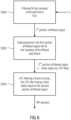
- Fig. 4shows a flow diagram for processing a current frame of the audio signal in accordance with an embodiment of the inventive approach.
- the processing of the current framewill be described, and the past frame is assumed to be already processed with the same technique described below.
- step S100a current frame of the audio signal is received.
- the current frameis filtered in step S102, for example in a way as described above with regard to Figs. 1 and 2 (see filter block 102).
- a discontinuity between the filtered past frame n-1 and the filtered current frame nsee Fig.
- the filtered current frameis processed by applying linear predictive filtering to at least a part of the filtered current frame.
- the discontinuitymay be removed by modifying a beginning portion of the filtered current frame by a signal obtained by linear predictive filtering a predefined signal with initial states of the linear predictive coding filter defined on the basis of a last part of the past frame.
- the initial states of the linear predictive coding filtermay be defined on the basis of a last part of the past frame filtered using the set of filter parameters for the current frame.
- the inventive approachis advantageous as it does not require filtering the current frame of an audio signal with a filter coefficient that is used for the past frame and thereby avoids problems that arise due to the mismatch of the filter parameters for the current frame and for the past frame as they are experienced in the prior art approaches described above with reference to Fig. 2 .
- Fig. 5shows a schematic block diagram for processing a current audio frame of the audio signal in accordance with embodiments of the present invention avoiding undesired distortion in the output signal despite the removal of the discontinuities.
- a current frame n of the audio signal 100is received, each frame of the audio signal 100 having a plurality of samples.
- the current frame n of the audio signal 100is processed by the filter block 102.
- the filtered current frameis further processed on the basis of ZIR samples as is schematically shown by block 110.
- the ZIR samplesare produced as is schematically shown by block 112.
- Fig. 6shows a flow diagram representing the functionality of the processing block 112 for generating the ZIR samples.
- the frames of an audio signal 100are filtered with a linear filter H(z) using filter parameters c selected or determined for the respective frame.
- the filter H(z)may be a recursive filer, e.g., an IIR filter, or it may be a non-recursive filter, e.g., a FIR filter.
- a LPC filteris used which may or may not be quantized.
- the LPC filteris of the order M and may be either estimated on the filtered or non-filtered audio signal or may be the LPC filter that is also used in an audio codec.
- Step S200thereby produces a first portion of filtered signal.
- step S202the M last samples of the filtered past frame n-1 (the M last samples of the past frame filtered using the filter parameters or coefficients c 0 of the past frame n-1) are subtracted from the first portion of filtered signal provided by step S200, thereby producing a second portion of filtered signal.
- step S204the LPC filter having the order M is applied, more specifically a zero input response (ZIR) of the LPC filter is generated in step S204 by filtering a frame of zero samples, wherein the initial states of the filter are equal to the second portion of filtered signals, thereby generating the ZIR.
- the ZIRcan be windowed such that its amplitude decreases faster to 0.
- filtering the current frame ncomprises processing (filtering) the current frame n on a sample-by-sample basis, wherein the samples of the beginning portion are treated in accordance with the inventive approach.
- M samples of a beginning portion of the current frame nare processed, and at a first step S300 the variables m is set to 0.
- the sample m of the current frame nis filtered using the filter H(z) and the filter coefficients or parameters c 1 for the current frame n.
- Step S302yields a filtered sample m
- step S304the ZIR sample corresponding to sample m is subtracted from the filtered sample m yielding the corresponding sample of the filtered current frame n.
- step S306it is determined whether the last sample M of the beginning portion of the current frame n is processed. In case not all M samples of the beginning portions have been processed, the variable m is incremented and the method steps S302 to S306 are repeated for the next sample of the current frame n.
- step S308the remaining samples of the current frame n are filtered using the filter parameters of the current frame c 1 , thereby providing the filtered current frame n processed in accordance with the inventive approach avoiding undesired distortion upon removal of the discontinuities between consecutive frames.
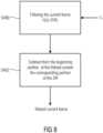
- the linear filer H(z)is a non-recursive filter, like a FIR filter, and the ZIR, as described above with regard to Fig. 5 , is applied in the processing block 110.
- the functionality of this embodimentis described with reference to the flow diagram of Fig. 8 .
- the current frame nat step S400, is filtered with the filter H(z) using the filter coefficients or parameters c 1 for the current frame.
- the current framein accordance with the inventive approach, is not filtered using coefficients from the past frame, but only coefficients from the current frame, which as a consequence avoids the undesired distortion which exist in conventional approaches despite the fact that discontinuities are removed.
- step S402a beginning portion of the ZIR is subtracted from a corresponding beginning portion of the filtered current frame, thereby providing the filtered current frame n having the beginning portion filtered/processed in accordance with the inventive approach and the remaining part only filtered using filter coefficients or parameters c 1 for the current frame, thereby avoiding undesired distortion upon removal of the discontinuities between consecutive frames.
- the inventive approachmay be applied in situations as described above when the audio signal is filtered.
- the inventive approachmay also be applied at the decoder side, for example, when using an audio codec postfilter for reducing the level of coding noise between signal harmonics.
- the filtermay also introduce a discontinuity between the two filtered frames, for example when the past filter frame parameters c 0 are different from the current frame filter parameters c 1 , and such a discontinuity may produce an artifact in the filtered audio signal 104, for example a "click".
- This discontinuityis removed by processing the filtered current frame as described above in detail.
- aspects of the described concepthave been described in the context of an apparatus, it is clear that these aspects also represent a description of the corresponding method, where a block or device corresponds to a method step or a feature of a method step. Analogously, aspects described in the context of a method step also represent a description of a corresponding block or item or feature of a corresponding apparatus.
- embodiments of the inventioncan be implemented in hardware or in software.
- the implementationcan be performed using a digital storage medium, for example a floppy disk, a DVD, a Blue-Ray, a CD, a ROM, a PROM, an EPROM, an EEPROM or a FLASH memory, having electronically readable control signals stored thereon, which cooperate (or are capable of cooperating) with a programmable computer system such that the respective method is performed. Therefore, the digital storage medium may be computer readable.
- Some embodiments according to the inventioncomprise a data carrier having electronically readable control signals, which are capable of cooperating with a programmable computer system, such that one of the methods described herein is performed.
- embodiments of the present inventioncan be implemented as a computer program product with a program code, the program code being operative for performing one of the methods when the computer program product runs on a computer.
- the program codemay for example be stored on a machine readable carrier.
- inventionscomprise the computer program for performing one of the methods described herein, stored on a machine readable carrier.
- an embodiment of the inventive methodis, therefore, a computer program having a program code for performing one of the methods described herein, when the computer program runs on a computer.
- a further embodiment of the inventive methodsis, therefore, a data carrier (or a digital storage medium, or a computer-readable medium) comprising, recorded thereon, the computer program for performing one of the methods described herein.
- a further embodiment of the inventive methodis, therefore, a data stream or a sequence of signals representing the computer program for performing one of the methods described herein.
- the data stream or the sequence of signalsmay for example be configured to be transferred via a data communication connection, for example via the Internet.
- a further embodimentcomprises a processing means, for example a computer, or a programmable logic device, configured to or adapted to perform one of the methods described herein.
- a processing meansfor example a computer, or a programmable logic device, configured to or adapted to perform one of the methods described herein.
- a further embodimentcomprises a computer having installed thereon the computer program for performing one of the methods described herein.
- a programmable logic devicefor example a field programmable gate array
- a field programmable gate arraymay cooperate with a microprocessor in order to perform one of the methods described herein.
- the methodsare preferably performed by any hardware apparatus.
Landscapes
- Engineering & Computer Science (AREA)
- Physics & Mathematics (AREA)
- Multimedia (AREA)
- Health & Medical Sciences (AREA)
- Audiology, Speech & Language Pathology (AREA)
- Human Computer Interaction (AREA)
- Signal Processing (AREA)
- Acoustics & Sound (AREA)
- Computational Linguistics (AREA)
- Spectroscopy & Molecular Physics (AREA)
- Quality & Reliability (AREA)
- Theoretical Computer Science (AREA)
- Compression, Expansion, Code Conversion, And Decoders (AREA)
- Signal Processing For Digital Recording And Reproducing (AREA)
- Transmission Systems Not Characterized By The Medium Used For Transmission (AREA)
- Soundproofing, Sound Blocking, And Sound Damping (AREA)
- Circuit For Audible Band Transducer (AREA)
- Stereophonic System (AREA)
Description
- The present invention relates to the field of audio signals, more specifically to an approach for processing an audio signal including a plurality of audio frames, wherein discontinuities between consecutive filtered audio frames are reduced or omitted.
- In the field of audio signal processing, an audio signal may be filtered for various reasons, e.g., a long-term prediction filter may be used in an audio signal encoder, to attenuate or even suppress completely a set of harmonics in the audio signal.
- The audio signal includes a plurality of audio frames, and the frames are filtered using the long-term prediction filter. When considering two consecutive frames of an audio signal, a past frame and a current frame, a linear filter H(z) having a set of parametersc is used for filtering the audio signal. More specifically, the past frame is filtered with the filter H(z) using a first set of parametersc0 which will produce a so-called filtered past frame. The current frame is filtered with the filter H(z) using a set of parametersc1 which will produce a filtered current frame.
Fig. 1 shows a block diagram for processing consecutive frames of an audio signal in accordance with a known approach. Anaudio signal 100 including a plurality of audio frames is provided. Theaudio signal 100 is supplied to afilter block 102 and a current frame n of theaudio signal 100 is filtered. The filter block, besides theaudio signal 100, receives a set of filter parameterscn for the current frame of the audio signal. Thefilter block 102 filters the current frame n of the audio signal and outputs a filteredaudio signal 104 including consecutive filtered frames. InFig. 1 , the filtered current frame n, the filtered past frame n-1 and the filtered second last frame n-2 are schematically depicted. The filtered frames are schematically represented inFig. 1 with respective gaps therebetween for schematically indicating adiscontinuity filter block 102 causes filtering of the frames of the audio signal using respective filter parametersc0 andc1 for a past frame n-1 and a current frame n. In general, thefilter block 102 may be a linear filter H(z), and one example for such a linear filter H(z) is the above mentioned long-term prediction filter

discontinuity Fig. 1 ) between the filtered past frame n-1 and the filtered current frame n when using such a long-term prediction filter and when the past frame filter parametersc0 are different from the current frame filter parametersc1. This discontinuity may produce an artifact in the filteredaudio signal 104, for example a "click". - Consequently, in view of the above described problems with the filtering of consecutive frames resulting in discontinuities which, in turn, may produce undesired artifacts, a technique is needed that removes a possible discontinuity. Several prior art approaches dealing with the removal of a discontinuity of filtered frames of an audio signal are known in the art.
- In case the linear filter H(z) is a FIR filter, the current frame is filtered with the filter parametersc1 of the current frame for producing a filtered current frame. In addition, a beginning portion of the current frame is filtered with the filter parameters of the past framec0 for producing a filtered frame portion, and then an overlap-add or cross-fade operation is performed over the beginning portion of the filtered current frame and the filtered frame portion.
Fig. 2 shows a block diagram of such a conventional approach for processing consecutive audio frames for removing a discontinuity. When compared toFig. 1 , thefilter block 102 includes afurther processing block 108 for performing the overlap-add or cross-fade operation. In the filteredaudio signal 104, there will be no or a reduced discontinuity between the consecutive filtered frames, as is schematically indicated inFig. 2 showing the consecutive filtered frames n, n-1 and n-2 without the gaps ofFig. 1 . - In other prior art approaches, the filter H(z) may be a filter having a recursive part, for example an IIR filter. In such a case, the approach as described above with regard to
Fig. 2 is applied on a sample-by-sample basis. In a first step, the processing starts with the first sample of the beginning portion of the current frame n being filtered with the filter parametersc0 of the past frame n-1 yielding a first filtered sample. The sample is also filtered with the filter parametersc1 of the current frame n producing a second filtered sample. Then, the overlap-add or cross-fade operation is performed based on the first and second filtered samples which yields the corresponding sample of the filtered current frame n. Then the next sample is processed and the above steps are repeated until the last sample of the beginning portion of the current frame n has been processed. The remaining samples of the current frame n are filtered with the filter parameters c1 of the current frame n. - Examples for the above mentioned known approaches for removing a discontinuity from consecutive filtered frames are described, for example, in
US 5,012,517 A in the context of a transform coder, inEP 0732687 A2 in the context of a speech bandwidth expander, inUS 5,999,899 A in the context of a transform audio coder, or inUS 7,353,168 B2 in the context of a decoded speech postfilter. - While the above approaches are efficient for removing the undesired signal discontinuities, since these approaches operate on a specific portion of the current frame, the beginning portion, for being effective, the length of the frame portion has to be sufficiently long, for example in the case of a frame length of 20 ms, the frame portion or beginning portion length could be as long as 5 ms. In certain cases, this can be too long, especially in situations where the past frame filter parameters c0 will not apply well to the current frame and this may result in additional artifacts. One example is a harmonic audio signal with fast changing pitch, and a long-term prediction filter that is designed to reduce the amplitude of the harmonics. In that case, the pitch-lag is different from one frame to the next. The long-term prediction filter with the pitch estimated in the current frame would effectively reduce the amplitude of the harmonics in the current frame, but it would not reduce the amplitude of the harmonics if used in another frame (e.g. beginning portion of the next frame) where the pitch of the audio signal would be different. It could even make things worse, by reducing the amplitude of non-harmonic-related components in the signal, introducing a distortion in the signal
WO 2011/085483 A1 describes a method for producing forward aliasing cancellation (FAC) parameters for cancelling time-domain aliasing caused to a coded audio signal in a first transform-coded frame by a transition between the first transform-coded frame using a first coding mode with overlapping window and a second frame using a second coding mode with non-overlapping window. The method includes calculating a FAC target representative of a difference between the audio signal of the first frame prior to coding and a synthesis of the coded audio signal of the first transform-coded frame; and weighting the FAC target to produce the FAC parameters. In a decoder, weighted forward aliasing cancellation (FAC) parameters are received and inverse weighted to produce a FAC synthesis. Upon synthesis of the coded audio signal in the first frame, the time-domain aliasing is cancelled from the audio signal synthesis using the FAC synthesis.US 2009/083047 A1 describes circuits and methods for providing zero-gap playback of consecutive data streams in portable electronic devices, such as media players. A circuit includes a decoder circuit configured to receive encoded audio data and to output decoded audio data including data streams associated with a data file and a subsequent data file. Moreover, a predictive circuit, which is electrically coupled to the decoder circuit, is configured to selectively generate additional samples based on samples in the data file, where the additional samples correspond to times after the end of a data stream associated with the data file. Additionally, a filter circuit, which is electrically coupled to the decoder circuit and selectively electrically coupled to the predictive circuit, is configured to selectively combine or blend samples at a beginning of the subsequent data file with the additional samples.- It is an object underlying the present invention to provide an improved approach for removing discontinuities among filtered audio frames without producing any potential distortion in the filtered audio signal.
- This object is achieved by a method and an apparatus according to the independent claims.
- The present invention provides a method for processing an audio signal, the method comprising using linear predictive filtering for removing a discontinuity between a filtered past frame and a filtered current frame of the audio signal. the method comprises filtering the current frame of the audio signal and removing the discontinuity by modifying a beginning portion of the filtered current frame by a signal obtained by linear predictive filtering a predefined signal with initial states of the linear predictive filter defined on the basis of a last part of the unfiltered past frame filtered using the set of filter parameters for filtering the current frame, and the linear predictive filter is defined as

- In accordance with embodiments, the method comprises estimating the linear predictive filter on the filtered or non-filtered audio signal.
- In accordance with embodiments, estimating the linear predictive filter comprises estimating the filter based on the past or current frame of the audio signal or based on the past filtered frame of the audio signal using the Levinson-Durbin algorithm.
- In accordance with embodiments, the linear predictive filter comprises a linear predictive filter of an audio codec.
- In accordance with embodiments, removing the discontinuity comprises processing the beginning portion of the filtered current frame, wherein the beginning portion of the current frame has a predefined number of samples being less or equal than the total number of samples in the current frame, and wherein processing the beginning portion of the current frame comprises subtracting a beginning portion of a zero-input-response (ZIR) from the beginning portion of the filtered current frame.
- In accordance with embodiments, the method comprises filtering the current frame of the audio signal using a non-recursive filter, like a FIR filter, for producing the filtered current frame.
- In accordance with embodiments, the method comprises processing the unfiltered current frame of the audio signal on a sample-by-sample basis using a recursive filter, like an IIR filter, and wherein processing a sample of the beginning portion of the current frame comprises:
- filtering the sample with the recursive filter using the filter parameters of the current frame for producing a filtered sample, and
- subtracting a corresponding ZIR sample from the filtered sample for producing the corresponding sample of the filtered current frame.
- In accordance with embodiments, filtering and subtracting are repeated until the last sample in the beginning portion of the current frame is processed, and wherein the method further comprises filtering the remaining samples in the current frame with the recursive filter using the filter parameters of the current frame.
- In accordance with embodiments, the method comprises generating the ZIR, wherein generating the ZIR comprises:
- filtering the M last samples of the unfiltered past frame with the filter and the filter parameters used for filtering the current frame for producing a first portion of filtered signal, wherein M is the linear predictive filter order,
- subtracting from the first portion of filtered signal the M last samples of the filtered past frame, filtered using the filter parameters of the past frame, for generating a second portion of filtered signal, and
- generating a ZIR of a linear predictive filter by filtering a frame of zero samples with the linear predictive filter and initial states equal to the second portion of filtered signal.
- In accordance with embodiments, the method comprises windowing the ZIR such that its amplitude decreases faster to zero.
- The present invention is based on the inventor's findings that the problems that have been recognized in conventional approaches for removing signal discontinuities which result in the additional unwanted distortion mentioned above, are mainly due to the processing of the current frame or at least a portion thereof on the basis of the filter parameters for the past frame. In accordance with the inventive approach this is avoided, i.e. the inventive approach does not filter a portion of the current frame with the filter parameters of the past frame and thus avoids the problems mentioned above. In accordance with embodiments, for removing the discontinuity, an LPC filter (linear predictive filter) is used for removing the discontinuity. The LPC filter may be estimated on the audio signal and therefore it is a good model of the spectral shape of the audio signal so that, when using the LPC filter, the spectral shape of the audio signal will mask the discontinuity. In an embodiment, the LPC filter may be estimated on the basis of the non-filtered audio signal or on the basis of an audio signal that has been filtered by a linear filter H(z) mentioned above. In accordance with embodiments, the LPC filter may be estimated by using the audio signal, for example the current frame and/or the past frame, and the Levinson-Durbin algorithm. It may also be computed only on the basis of the past filtered frame signal using the Levinson-Durbin algorithm.
- In yet other embodiments, an audio codec for processing the audio signal may use a linear filter H(z) and may also use an LPC filter, either quantized or not, for example to shape the quantization noise in a transform-based audio codec. In such an embodiment, this existing LPC filter can be directly used for smoothing the discontinuity without the additional complexity needed to estimate a new LPC filter.
- In the following, embodiments for illustrating the present invention will be described with reference to the accompanying drawings, in which:
- Fig. 1
- shows a block diagram for processing consecutive frames of an audio signal in accordance with a conventional approach,
- Fig. 2
- shows a block diagram of another conventional approach for processing consecutive audio frames for removing a discontinuity,
- Fig. 3
- shows a simplified block diagram of a system for transmitting audio signals implementing the inventive approach for removing a discontinuity between consecutive frames of an audio signal at the encoder side and/or at the decoder side,
- Fig. 4
- shows a flow diagram depicting the inventive approach for removing a discontinuity between consecutive frames of an audio signal in accordance with an embodiment,
- Fig. 5
- shows a schematic block diagram for processing a current audio frame in accordance with embodiments of the present invention avoiding undesired distortion in the output signal despite the removal of the discontinuities,
- Fig. 6
- shows a flow diagram representing the functionality of the block in
Fig. 5 for generating the ZIR, - Fig. 7
- shows a flow diagram representing the functionality of the block in
Fig. 5 for processing the filtered current frame beginning portion in case the filter block comprises a recursive filter, like an IIR filter, and - Fig. 8
- shows a flow diagram representing the functionality of the block in
Fig. 5 for processing the filtered current frame beginning portion in case the filter block comprises a non-recursive filter, like a FIR filter. - In the following, embodiments of the inventive approach will be described in further detail and it is noted that in the accompanying drawing elements having the same or similar functionality are denoted by the same reference signs.
Fig. 3 shows a simplified block diagram of a system for transmitting audio signals implementing the inventive approach at the encoder side and/or at the decoder side. The system ofFig. 3 comprises anencoder 200 receiving at aninput 202 anaudio signal 204. The encoder includes anencoding processor 206 receiving theaudio signal 204 and generating an encoded audio signal that is provided at anoutput 208 of the encoder. The encoding processor may be programmed or built to implement the inventive approach for processing consecutive audio frames of the audio signal received to avoid discontinuities. In other embodiments the encoder does not need to be part of a transmission system, however, it can be a standalone device generating encoded audio signals or it may be part of an audio signal transmitter. In accordance with an embodiment, theencoder 200 may comprise anantenna 210 to allow for a wireless transmission of the audio signal, as is indicated at 212. In other embodiments, theencoder 200 may output the encoded audio signal provided at theoutput 208 using a wired connection line, as it is for example indicated atreference sign 214.- The system of
Fig. 3 further comprises adecoder 250 having aninput 252 receiving an encoded audio signal to be processed by thedecoder 250, e.g. via thewired line 214 or via anantenna 254. Thedecoder 250 comprises adecoding processor 256 operating on the encoded signal and providing a decodedaudio signal 258 at anoutput 260. Thedecoding processor 256 may be implemented to operate in accordance with the inventive approach on consecutive frames that are filtered in such a way that discontinuities are avoided. In other embodiments the decoder does not need to be part of a transmission system, rather, it may be a standalone device for decoding encoded audio signals or it may be part of an audio signal receiver. - In the following, embodiments of the inventive approach that may be implemented in at least one of the
encoding processor 206 and thedecoding processor 256 will be described in further detail.Fig. 4 shows a flow diagram for processing a current frame of the audio signal in accordance with an embodiment of the inventive approach. The processing of the current frame will be described, and the past frame is assumed to be already processed with the same technique described below. In accordance with the present invention, in step S100 a current frame of the audio signal is received. The current frame is filtered in step S102, for example in a way as described above with regard toFigs. 1 and 2 (see filter block 102). In accordance with the inventive approach, a discontinuity between the filtered past frame n-1 and the filtered current frame n (seeFig. 1 or 2 ) will be removed using linear predictive filtering as is indicated at step S104, and the linear predictive filter is defined as
Fig. 2 . Fig. 5 shows a schematic block diagram for processing a current audio frame of the audio signal in accordance with embodiments of the present invention avoiding undesired distortion in the output signal despite the removal of the discontinuities. InFig. 5 , the same reference signs as inFigs. 1 and 2 are used. A current frame n of theaudio signal 100 is received, each frame of theaudio signal 100 having a plurality of samples. The current frame n of theaudio signal 100 is processed by thefilter block 102. When compared to the prior art approaches ofFigs. 1 and 2 , in accordance with embodiments as described with regard toFig. 5 , the filtered current frame is further processed on the basis of ZIR samples as is schematically shown byblock 110. In accordance with an embodiment on the basis of the past frame n-1, and on the basis of an LPC filter the ZIR samples are produced as is schematically shown byblock 112.- The functionality of the processing blocks 110 and 112 will now be described in further detail.
Fig. 6 shows a flow diagram representing the functionality of theprocessing block 112 for generating the ZIR samples. As mentioned above, the frames of anaudio signal 100 are filtered with a linear filter H(z) using filter parameters c selected or determined for the respective frame. The filter H(z) may be a recursive filer, e.g., an IIR filter, or it may be a non-recursive filter, e.g., a FIR filter. In the processing block 112 a LPC filter is used which may or may not be quantized. The LPC filter is of the order M and may be either estimated on the filtered or non-filtered audio signal or may be the LPC filter that is also used in an audio codec. In a first step S200, the M (M = the order of the LPC filter) last samples of the past frame n-1 are filtered with the filter H(z) using, however, the filter parameters or coefficientsc1 of the current frame n. Step S200 thereby produces a first portion of filtered signal. In step S202 the M last samples of the filtered past frame n-1 (the M last samples of the past frame filtered using the filter parameters or coefficients c0 of the past frame n-1) are subtracted from the first portion of filtered signal provided by step S200, thereby producing a second portion of filtered signal. In step S204 the LPC filter having the order M is applied, more specifically a zero input response (ZIR) of the LPC filter is generated in step S204 by filtering a frame of zero samples, wherein the initial states of the filter are equal to the second portion of filtered signals, thereby generating the ZIR. In accordance with embodiments, the ZIR can be windowed such that its amplitude decreases faster to 0. - The ZIR, as described above with regard to
Fig. 5 , is applied in theprocessing block 110, the functionality of which is described with reference to the flow diagram ofFig. 7 for the case of using, as the linear filer H(z), a recursive filter, like an IIR filter. In accordance with the embodiment described with regard toFig. 5 , to remove discontinuities between the current frame and the past frame while avoiding undesired distortions, filtering the current frame n comprises processing (filtering) the current frame n on a sample-by-sample basis, wherein the samples of the beginning portion are treated in accordance with the inventive approach. To be more specific, M samples of a beginning portion of the current frame n are processed, and at a first step S300 the variables m is set to 0. In a next step S302, the sample m of the current frame n is filtered using the filter H(z) and the filter coefficients or parametersc1 for the current frame n. Thus, other than in conventional approaches, the current frame, in accordance with the inventive approach, is not filtered using coefficients from the past frame, but only coefficients from the current frame, which as a consequence avoids the undesired distortion which exist in conventional approaches despite the fact that discontinuities are removed. Step S302 yields a filtered sample m, and in step S304 the ZIR sample corresponding to sample m is subtracted from the filtered sample m yielding the corresponding sample of the filtered current frame n. In step S306 it is determined whether the last sample M of the beginning portion of the current frame n is processed. In case not all M samples of the beginning portions have been processed, the variable m is incremented and the method steps S302 to S306 are repeated for the next sample of the current frame n. Once all M samples of the beginning portions have been processed, at step S308 the remaining samples of the current frame n are filtered using the filter parameters of the current framec1, thereby providing the filtered current frame n processed in accordance with the inventive approach avoiding undesired distortion upon removal of the discontinuities between consecutive frames. - In accordance with another embodiment, the linear filer H(z) is a non-recursive filter, like a FIR filter, and the ZIR, as described above with regard to
Fig. 5 , is applied in theprocessing block 110. The functionality of this embodiment is described with reference to the flow diagram ofFig. 8 . The current frame n, at step S400, is filtered with the filter H(z) using the filter coefficients or parametersc1 for the current frame. Thus, other than in conventional approaches, the current frame, in accordance with the inventive approach, is not filtered using coefficients from the past frame, but only coefficients from the current frame, which as a consequence avoids the undesired distortion which exist in conventional approaches despite the fact that discontinuities are removed. In step S402 a beginning portion of the ZIR is subtracted from a corresponding beginning portion of the filtered current frame, thereby providing the filtered current frame n having the beginning portion filtered/processed in accordance with the inventive approach and the remaining part only filtered using filter coefficients or parametersc1 for the current frame, thereby avoiding undesired distortion upon removal of the discontinuities between consecutive frames. - The inventive approach may be applied in situations as described above when the audio signal is filtered. In accordance with embodiments, the inventive approach may also be applied at the decoder side, for example, when using an audio codec postfilter for reducing the level of coding noise between signal harmonics. For processing the audio frames at the decoder the postfilter, in accordance with an embodiment, may be as follows:

audio signal 104, for example a "click". This discontinuity is removed by processing the filtered current frame as described above in detail. - Although some aspects of the described concept have been described in the context of an apparatus, it is clear that these aspects also represent a description of the corresponding method, where a block or device corresponds to a method step or a feature of a method step. Analogously, aspects described in the context of a method step also represent a description of a corresponding block or item or feature of a corresponding apparatus.
- Depending on certain implementation requirements, embodiments of the invention can be implemented in hardware or in software. The implementation can be performed using a digital storage medium, for example a floppy disk, a DVD, a Blue-Ray, a CD, a ROM, a PROM, an EPROM, an EEPROM or a FLASH memory, having electronically readable control signals stored thereon, which cooperate (or are capable of cooperating) with a programmable computer system such that the respective method is performed. Therefore, the digital storage medium may be computer readable.
- Some embodiments according to the invention comprise a data carrier having electronically readable control signals, which are capable of cooperating with a programmable computer system, such that one of the methods described herein is performed.
- Generally, embodiments of the present invention can be implemented as a computer program product with a program code, the program code being operative for performing one of the methods when the computer program product runs on a computer. The program code may for example be stored on a machine readable carrier.
- Other embodiments comprise the computer program for performing one of the methods described herein, stored on a machine readable carrier.
- In other words, an embodiment of the inventive method is, therefore, a computer program having a program code for performing one of the methods described herein, when the computer program runs on a computer.
- A further embodiment of the inventive methods is, therefore, a data carrier (or a digital storage medium, or a computer-readable medium) comprising, recorded thereon, the computer program for performing one of the methods described herein.
- A further embodiment of the inventive method is, therefore, a data stream or a sequence of signals representing the computer program for performing one of the methods described herein. The data stream or the sequence of signals may for example be configured to be transferred via a data communication connection, for example via the Internet.
- A further embodiment comprises a processing means, for example a computer, or a programmable logic device, configured to or adapted to perform one of the methods described herein.
- A further embodiment comprises a computer having installed thereon the computer program for performing one of the methods described herein.
- In some embodiments, a programmable logic device (for example a field programmable gate array) may be used to perform some or all of the functionalities of the methods described herein. In some embodiments, a field programmable gate array may cooperate with a microprocessor in order to perform one of the methods described herein. Generally, the methods are preferably performed by any hardware apparatus.
- The above described embodiments are merely illustrative for the principles of the present invention. It is understood that modifications and variations of the arrangements and the details described herein will be apparent to others skilled in the art. It is the intent, therefore, to be limited only by the scope of the impending patent claims and not by the specific details presented by way of description and explanation of the embodiments herein.


Claims (14)
- A method for processing an audio signal (100), the method comprising:using linear predictive filtering for removing (S102, S104, S300-S308, S400-S402) a discontinuity (106a, 106b) between a filtered past frame and a filtered current frame of the audio signal,wherein the method comprises filtering the current frame of the audio signal and removing the discontinuity by modifying a beginning portion of the filtered current frame by a signal obtained by linear predictive filtering a predefined signal with initial states of the linear predictive filter defined on the basis of a last part of the unfiltered past frame filtered using the set of filter parameters for filtering the current frame,wherein the linear predictive filter is defined as
 wherein M is the linear predictive filter order, andwherein am indicates the filter coefficients, with a0 = 1.
 - The method of claim 1, further comprising estimating the linear predictive filter on the filtered or non-filtered audio signal (100).
- The method of claim 2, wherein estimating the linear predictive filter comprises estimating the filter based on the past and/or current frame of the audio signal (100) or based on the past filtered frame of the audio signal (100) using the Levinson-Durbin algorithm.
- The method of claim 1, wherein the linear predictive filter comprises a linear predictive filter of an audio codec.
- The method of one of claims 1 to 4, wherein removing the discontinuity comprises processing the beginning portion of the filtered current frame, wherein the beginning portion of the current frame has a predefined number of samples being less or equal than the total number of samples in the current frame, and wherein processing the beginning portion of the current frame comprises subtracting (S304, S402) a beginning portion of a zero-input-response (ZIR) from the beginning portion of the filtered current frame.
- The method of claim 5, comprising filtering (S400) the current frame of the audio signal using a non-recursive filter, like a FIR filter, for producing the filtered current frame.
- The method of claim 5, comprising processing the unfiltered current frame of the audio signal on a sample-by-sample basis using a recursive filter, like an IIR filter, and wherein processing a sample of the beginning portion of the current frame comprises:filtering (S302) the sample with the recursive filter using the filter parameters of the current frame for producing a filtered sample, andsubtracting (S304) a corresponding ZIR sample from the filtered sample for producing the corresponding sample of the filtered current frame.
- The method of claim 7, wherein filtering (S302) and subtracting (S304) are repeated until the last sample in the beginning portion of the current frame is processed, and wherein the method further comprises filtering (S306) the remaining samples in the current frame with the recursive filter using the filter parameters of the current frame.
- The method of one of claims 5 to 8, comprising generating the ZIR, wherein generating the ZIR comprises:filtering (S200) the M last samples of the unfiltered past frame with the filter and the filter parameters used for filtering the current frame for producing a first portion of filtered signal, wherein M is the order of the linear predictive filter,subtracting (S202) from the first portion of filtered signal the M last samples of the filtered past frame, filtered using the filter parameters of the past frame, for generating a second portion of filtered signal, andgenerating (S204) a ZIR of a linear predictive filter by filtering a frame of zero samples with the linear predictive filter and initial states equal to the second portion of filtered signal.
- The method of claim 9, comprising windowing the ZIR such that its amplitude decreases faster to zero.
- A computer readable medium comprising instructions which, when executed by a computer, cause the computer to carry out the method of one of claims 1 to 10.
- An apparatus for processing an audio signal (100), the apparatus comprising:a processor (102, 110, 112) configured to remove a discontinuity (106a, 106b) between a filtered past frame and a filtered current frame of the audio signal using linear predictive filtering,wherein the processor (102, 110, 112) is configured to filter the current frame of the audio signal and remove the discontinuity by modifying a beginning portion of the filtered current frame by a signal obtained by linear predictive filtering a predefined signal with initial states of the linear predictive filter defined on the basis of a last part of the unfiltered past frame filtered using the set of filter parameters for filtering the current frame,wherein the linear predictive filter is defined as
 wherein M is the linear predictive filter order, andwherein am indicates the filter coefficients, with a0 = 1.
 - An audio decoder (250), comprising an apparatus of claim 12.
- An audio encoder (200), comprising an apparatus of claim 12.


Priority Applications (2)
| Application Number | Priority Date | Filing Date | Title |
|---|---|---|---|
| EP23179786.1AEP4235667B1 (en) | 2014-07-28 | 2015-07-03 | Method and apparatus for processing an audio signal, computer readable medium and audio decoder |
| EP24198100.0AEP4447048B1 (en) | 2014-07-28 | 2015-07-03 | Method and apparatus for processing an audio signal, computer readable medium, audio decoder and audio encoder |
Applications Claiming Priority (5)
| Application Number | Priority Date | Filing Date | Title |
|---|---|---|---|
| EP14178821.6AEP2980796A1 (en) | 2014-07-28 | 2014-07-28 | Method and apparatus for processing an audio signal, audio decoder, and audio encoder |
| EP15732290.0AEP3175452B1 (en) | 2014-07-28 | 2015-07-03 | Method and apparatus for processing an audio signal, audio decoder, and audio encoder |
| EP18182785.8AEP3407351B1 (en) | 2014-07-28 | 2015-07-03 | Methods for encoding and decoding an audio signal, audio decoder and audio encoder |
| EP19209351.6AEP3654333B1 (en) | 2014-07-28 | 2015-07-03 | Method for processing an audio signal and audio decoder |
| PCT/EP2015/065219WO2016015950A1 (en) | 2014-07-28 | 2015-07-03 | Method and apparatus for precessing an audio signal, audio decoder, and audio encoder |
Related Parent Applications (3)
| Application Number | Title | Priority Date | Filing Date |
|---|---|---|---|
| EP15732290.0ADivisionEP3175452B1 (en) | 2014-07-28 | 2015-07-03 | Method and apparatus for processing an audio signal, audio decoder, and audio encoder |
| EP19209351.6ADivisionEP3654333B1 (en) | 2014-07-28 | 2015-07-03 | Method for processing an audio signal and audio decoder |
| EP18182785.8ADivisionEP3407351B1 (en) | 2014-07-28 | 2015-07-03 | Methods for encoding and decoding an audio signal, audio decoder and audio encoder |
Related Child Applications (3)
| Application Number | Title | Priority Date | Filing Date |
|---|---|---|---|
| EP23179786.1ADivisionEP4235667B1 (en) | 2014-07-28 | 2015-07-03 | Method and apparatus for processing an audio signal, computer readable medium and audio decoder |
| EP23179786.1ADivision-IntoEP4235667B1 (en) | 2014-07-28 | 2015-07-03 | Method and apparatus for processing an audio signal, computer readable medium and audio decoder |
| EP24198100.0ADivisionEP4447048B1 (en) | 2014-07-28 | 2015-07-03 | Method and apparatus for processing an audio signal, computer readable medium, audio decoder and audio encoder |
Publications (3)
| Publication Number | Publication Date |
|---|---|
| EP4030426A1 EP4030426A1 (en) | 2022-07-20 |
| EP4030426C0 EP4030426C0 (en) | 2023-08-16 |
| EP4030426B1true EP4030426B1 (en) | 2023-08-16 |
Family
ID=51224879
Family Applications (7)
| Application Number | Title | Priority Date | Filing Date |
|---|---|---|---|
| EP14178821.6AWithdrawnEP2980796A1 (en) | 2014-07-28 | 2014-07-28 | Method and apparatus for processing an audio signal, audio decoder, and audio encoder |
| EP24198100.0AActiveEP4447048B1 (en) | 2014-07-28 | 2015-07-03 | Method and apparatus for processing an audio signal, computer readable medium, audio decoder and audio encoder |
| EP19209351.6AActiveEP3654333B1 (en) | 2014-07-28 | 2015-07-03 | Method for processing an audio signal and audio decoder |
| EP22160064.6AActiveEP4030426B1 (en) | 2014-07-28 | 2015-07-03 | Method and apparatus for processing an audio signal, audio decoder and audio encoder |
| EP23179786.1AActiveEP4235667B1 (en) | 2014-07-28 | 2015-07-03 | Method and apparatus for processing an audio signal, computer readable medium and audio decoder |
| EP18182785.8AActiveEP3407351B1 (en) | 2014-07-28 | 2015-07-03 | Methods for encoding and decoding an audio signal, audio decoder and audio encoder |
| EP15732290.0AActiveEP3175452B1 (en) | 2014-07-28 | 2015-07-03 | Method and apparatus for processing an audio signal, audio decoder, and audio encoder |
Family Applications Before (3)
| Application Number | Title | Priority Date | Filing Date |
|---|---|---|---|
| EP14178821.6AWithdrawnEP2980796A1 (en) | 2014-07-28 | 2014-07-28 | Method and apparatus for processing an audio signal, audio decoder, and audio encoder |
| EP24198100.0AActiveEP4447048B1 (en) | 2014-07-28 | 2015-07-03 | Method and apparatus for processing an audio signal, computer readable medium, audio decoder and audio encoder |
| EP19209351.6AActiveEP3654333B1 (en) | 2014-07-28 | 2015-07-03 | Method for processing an audio signal and audio decoder |
Family Applications After (3)
| Application Number | Title | Priority Date | Filing Date |
|---|---|---|---|
| EP23179786.1AActiveEP4235667B1 (en) | 2014-07-28 | 2015-07-03 | Method and apparatus for processing an audio signal, computer readable medium and audio decoder |
| EP18182785.8AActiveEP3407351B1 (en) | 2014-07-28 | 2015-07-03 | Methods for encoding and decoding an audio signal, audio decoder and audio encoder |
| EP15732290.0AActiveEP3175452B1 (en) | 2014-07-28 | 2015-07-03 | Method and apparatus for processing an audio signal, audio decoder, and audio encoder |
Country Status (17)
| Country | Link |
|---|---|
| US (6) | US20170133028A1 (en) |
| EP (7) | EP2980796A1 (en) |
| JP (5) | JP6503051B2 (en) |
| KR (6) | KR102459857B1 (en) |
| CN (2) | CN113012704B (en) |
| AR (1) | AR101287A1 (en) |
| AU (1) | AU2015295709B2 (en) |
| CA (6) | CA2955674C (en) |
| ES (5) | ES2994941T3 (en) |
| MX (1) | MX362737B (en) |
| MY (1) | MY179016A (en) |
| PL (5) | PL3175452T3 (en) |
| PT (3) | PT3654333T (en) |
| RU (1) | RU2665282C1 (en) |
| SG (1) | SG11201700684YA (en) |
| TW (1) | TWI595480B (en) |
| WO (1) | WO2016015950A1 (en) |
Families Citing this family (12)
| Publication number | Priority date | Publication date | Assignee | Title |
|---|---|---|---|---|
| EP2980796A1 (en)* | 2014-07-28 | 2016-02-03 | Fraunhofer-Gesellschaft zur Förderung der angewandten Forschung e.V. | Method and apparatus for processing an audio signal, audio decoder, and audio encoder |
| WO2019091573A1 (en) | 2017-11-10 | 2019-05-16 | Fraunhofer-Gesellschaft zur Förderung der angewandten Forschung e.V. | Apparatus and method for encoding and decoding an audio signal using downsampling or interpolation of scale parameters |
| EP3483883A1 (en) | 2017-11-10 | 2019-05-15 | Fraunhofer-Gesellschaft zur Förderung der angewandten Forschung e.V. | Audio coding and decoding with selective postfiltering |
| EP3483886A1 (en) | 2017-11-10 | 2019-05-15 | Fraunhofer-Gesellschaft zur Förderung der angewandten Forschung e.V. | Selecting pitch lag |
| EP3483879A1 (en) | 2017-11-10 | 2019-05-15 | Fraunhofer-Gesellschaft zur Förderung der angewandten Forschung e.V. | Analysis/synthesis windowing function for modulated lapped transformation |
| EP3483884A1 (en) | 2017-11-10 | 2019-05-15 | Fraunhofer-Gesellschaft zur Förderung der angewandten Forschung e.V. | Signal filtering |
| WO2019091576A1 (en) | 2017-11-10 | 2019-05-16 | Fraunhofer-Gesellschaft zur Förderung der angewandten Forschung e.V. | Audio encoders, audio decoders, methods and computer programs adapting an encoding and decoding of least significant bits |
| EP3483878A1 (en) | 2017-11-10 | 2019-05-15 | Fraunhofer-Gesellschaft zur Förderung der angewandten Forschung e.V. | Audio decoder supporting a set of different loss concealment tools |
| EP3483882A1 (en) | 2017-11-10 | 2019-05-15 | Fraunhofer-Gesellschaft zur Förderung der angewandten Forschung e.V. | Controlling bandwidth in encoders and/or decoders |
| EP3483880A1 (en) | 2017-11-10 | 2019-05-15 | Fraunhofer-Gesellschaft zur Förderung der angewandten Forschung e.V. | Temporal noise shaping |
| CN119360866A (en)* | 2020-04-24 | 2025-01-24 | 瑞典爱立信有限公司 | Low-cost adaptation of bass post-filter |
| CN117040487B (en)* | 2023-10-08 | 2024-01-02 | 武汉海微科技有限公司 | Filtering method, device, equipment and storage medium for audio signal processing |
Family Cites Families (49)
| Publication number | Priority date | Publication date | Assignee | Title |
|---|---|---|---|---|
| US4969192A (en)* | 1987-04-06 | 1990-11-06 | Voicecraft, Inc. | Vector adaptive predictive coder for speech and audio |
| US5012517A (en) | 1989-04-18 | 1991-04-30 | Pacific Communication Science, Inc. | Adaptive transform coder having long term predictor |
| CA2568984C (en)* | 1991-06-11 | 2007-07-10 | Qualcomm Incorporated | Variable rate vocoder |
| US5784532A (en) | 1994-02-16 | 1998-07-21 | Qualcomm Incorporated | Application specific integrated circuit (ASIC) for performing rapid speech compression in a mobile telephone system |
| EP0732687B2 (en) | 1995-03-13 | 2005-10-12 | Matsushita Electric Industrial Co., Ltd. | Apparatus for expanding speech bandwidth |
| JP3653826B2 (en)* | 1995-10-26 | 2005-06-02 | ソニー株式会社 | Speech decoding method and apparatus |
| US5960389A (en)* | 1996-11-15 | 1999-09-28 | Nokia Mobile Phones Limited | Methods for generating comfort noise during discontinuous transmission |
| SE9700772D0 (en)* | 1997-03-03 | 1997-03-03 | Ericsson Telefon Ab L M | A high resolution post processing method for a speech decoder |
| FR2762464B1 (en)* | 1997-04-16 | 1999-06-25 | France Telecom | METHOD AND DEVICE FOR ENCODING AN AUDIO FREQUENCY SIGNAL BY "FORWARD" AND "BACK" LPC ANALYSIS |
| GB2326572A (en) | 1997-06-19 | 1998-12-23 | Softsound Limited | Low bit rate audio coder and decoder |
| US7072832B1 (en) | 1998-08-24 | 2006-07-04 | Mindspeed Technologies, Inc. | System for speech encoding having an adaptive encoding arrangement |
| GB2356538A (en)* | 1999-11-22 | 2001-05-23 | Mitel Corp | Comfort noise generation for open discontinuous transmission systems |
| US6584438B1 (en)* | 2000-04-24 | 2003-06-24 | Qualcomm Incorporated | Frame erasure compensation method in a variable rate speech coder |
| US7512535B2 (en) | 2001-10-03 | 2009-03-31 | Broadcom Corporation | Adaptive postfiltering methods and systems for decoding speech |
| US20040098255A1 (en)* | 2002-11-14 | 2004-05-20 | France Telecom | Generalized analysis-by-synthesis speech coding method, and coder implementing such method |
| AU2003302114A1 (en) | 2002-11-21 | 2004-06-15 | Nippon Telegraph And Telephone Corporation | Digital signal processing method, processor thereof, program thereof, and recording medium containing the program |
| US7613606B2 (en)* | 2003-10-02 | 2009-11-03 | Nokia Corporation | Speech codecs |
| CA2457988A1 (en)* | 2004-02-18 | 2005-08-18 | Voiceage Corporation | Methods and devices for audio compression based on acelp/tcx coding and multi-rate lattice vector quantization |
| US7930184B2 (en)* | 2004-08-04 | 2011-04-19 | Dts, Inc. | Multi-channel audio coding/decoding of random access points and transients |
| JP4606264B2 (en)* | 2005-07-19 | 2011-01-05 | 三洋電機株式会社 | Noise canceller |
| WO2007138511A1 (en)* | 2006-05-30 | 2007-12-06 | Koninklijke Philips Electronics N.V. | Linear predictive coding of an audio signal |
| CN101197134A (en)* | 2006-12-05 | 2008-06-11 | 华为技术有限公司 | Method and device for eliminating influence of coding mode switching, and decoding method and device |
| US8000969B2 (en)* | 2006-12-19 | 2011-08-16 | Nuance Communications, Inc. | Inferring switching conditions for switching between modalities in a speech application environment extended for interactive text exchanges |
| CN101231850B (en)* | 2007-01-23 | 2012-02-29 | 华为技术有限公司 | Codec method and device |
| US8069051B2 (en)* | 2007-09-25 | 2011-11-29 | Apple Inc. | Zero-gap playback using predictive mixing |
| CN101527138B (en)* | 2008-03-05 | 2011-12-28 | 华为技术有限公司 | Coding method and decoding method for ultra wide band expansion, coder and decoder as well as system for ultra wide band expansion |
| ES2895268T3 (en)* | 2008-03-20 | 2022-02-18 | Fraunhofer Ges Forschung | Apparatus and method for modifying a parameterized representation |
| EP2144171B1 (en)* | 2008-07-11 | 2018-05-16 | Fraunhofer-Gesellschaft zur Förderung der angewandten Forschung e.V. | Audio encoder and decoder for encoding and decoding frames of a sampled audio signal |
| PL2346030T3 (en)* | 2008-07-11 | 2015-03-31 | Fraunhofer Ges Forschung | Audio encoder, method for encoding an audio signal and computer program |
| MY152252A (en)* | 2008-07-11 | 2014-09-15 | Fraunhofer Ges Forschung | Apparatus and method for encoding/decoding an audio signal using an aliasing switch scheme |
| AU2009267394B2 (en)* | 2008-07-11 | 2012-10-18 | Fraunhofer-Gesellschaft Zur Foerderung Der Angewandten Forschung E.V. | Audio encoder and decoder for encoding frames of sampled audio signals |
| KR20100007738A (en)* | 2008-07-14 | 2010-01-22 | 한국전자통신연구원 | Apparatus for encoding and decoding of integrated voice and music |
| CN101355692B (en)* | 2008-07-30 | 2013-03-20 | 浙江大学 | Intelligent monitoring apparatus for real time tracking motion target area |
| EP2169670B1 (en)* | 2008-09-25 | 2016-07-20 | LG Electronics Inc. | An apparatus for processing an audio signal and method thereof |
| EP3352168B1 (en)* | 2009-06-23 | 2020-09-16 | VoiceAge Corporation | Forward time-domain aliasing cancellation with application in weighted or original signal domain |
| KR101734948B1 (en) | 2009-10-09 | 2017-05-12 | 삼성전자주식회사 | Method of Power Headroom Report, Resource Allocation and Power Control |
| EP4362014B1 (en)* | 2009-10-20 | 2025-04-23 | Fraunhofer-Gesellschaft zur Förderung der angewandten Forschung e.V. | Audio signal decoder, corresponding method and computer program |
| TR201900663T4 (en)* | 2010-01-13 | 2019-02-21 | Voiceage Corp | Audio decoding with forward time domain cancellation using linear predictive filtering. |
| US8423355B2 (en)* | 2010-03-05 | 2013-04-16 | Motorola Mobility Llc | Encoder for audio signal including generic audio and speech frames |
| EP4398247B1 (en)* | 2010-07-08 | 2025-09-10 | Fraunhofer-Gesellschaft zur Förderung der angewandten Forschung e.V. | Coder using forward aliasing cancellation |
| CN101976566B (en)* | 2010-07-09 | 2012-05-02 | 瑞声声学科技(深圳)有限公司 | Speech enhancement method and device applying the method |
| US8738385B2 (en)* | 2010-10-20 | 2014-05-27 | Broadcom Corporation | Pitch-based pre-filtering and post-filtering for compression of audio signals |
| FR2969805A1 (en)* | 2010-12-23 | 2012-06-29 | France Telecom | LOW ALTERNATE CUSTOM CODING PREDICTIVE CODING AND TRANSFORMED CODING |
| US9037456B2 (en) | 2011-07-26 | 2015-05-19 | Google Technology Holdings LLC | Method and apparatus for audio coding and decoding |
| CN102368385B (en)* | 2011-09-07 | 2013-08-14 | 中科开元信息技术(北京)有限公司 | Backward block adaptive Golomb-Rice coding and decoding method and apparatus thereof |
| US9043201B2 (en)* | 2012-01-03 | 2015-05-26 | Google Technology Holdings LLC | Method and apparatus for processing audio frames to transition between different codecs |
| WO2013168414A1 (en)* | 2012-05-11 | 2013-11-14 | パナソニック株式会社 | Hybrid audio signal encoder, hybrid audio signal decoder, method for encoding audio signal, and method for decoding audio signal |
| EP2980797A1 (en)* | 2014-07-28 | 2016-02-03 | Fraunhofer-Gesellschaft zur Förderung der angewandten Forschung e.V. | Audio decoder, method and computer program using a zero-input-response to obtain a smooth transition |
| EP2980796A1 (en)* | 2014-07-28 | 2016-02-03 | Fraunhofer-Gesellschaft zur Förderung der angewandten Forschung e.V. | Method and apparatus for processing an audio signal, audio decoder, and audio encoder |
- 2014
- 2014-07-28EPEP14178821.6Apatent/EP2980796A1/ennot_activeWithdrawn
- 2015
- 2015-07-03ESES23179786Tpatent/ES2994941T3/enactiveActive
- 2015-07-03EPEP24198100.0Apatent/EP4447048B1/enactiveActive
- 2015-07-03JPJP2017504689Apatent/JP6503051B2/enactiveActive
- 2015-07-03SGSG11201700684YApatent/SG11201700684YA/enunknown
- 2015-07-03KRKR1020217029645Apatent/KR102459857B1/enactiveActive
- 2015-07-03PTPT192093516Tpatent/PT3654333T/enunknown
- 2015-07-03CACA2955674Apatent/CA2955674C/enactiveActive
- 2015-07-03ESES15732290.0Tpatent/ES2685984T3/enactiveActive
- 2015-07-03CACA3193319Apatent/CA3193319A1/enactivePending
- 2015-07-03KRKR1020177005450Apatent/KR101997006B1/enactiveActive
- 2015-07-03AUAU2015295709Apatent/AU2015295709B2/enactiveActive
- 2015-07-03KRKR1020247042711Apatent/KR20250008957A/enactivePending
- 2015-07-03PLPL15732290Tpatent/PL3175452T3/enunknown
- 2015-07-03CACA3193309Apatent/CA3193309A1/enactivePending
- 2015-07-03MYMYPI2017000131Apatent/MY179016A/enunknown
- 2015-07-03EPEP19209351.6Apatent/EP3654333B1/enactiveActive
- 2015-07-03KRKR1020227036973Apatent/KR102615475B1/enactiveActive
- 2015-07-03CACA3193316Apatent/CA3193316A1/enactivePending
- 2015-07-03KRKR1020197018895Apatent/KR102304326B1/enactiveActive
- 2015-07-03RURU2017105447Apatent/RU2665282C1/enactive
- 2015-07-03EPEP22160064.6Apatent/EP4030426B1/enactiveActive
- 2015-07-03WOPCT/EP2015/065219patent/WO2016015950A1/enactiveApplication Filing
- 2015-07-03ESES22160064Tpatent/ES2960422T3/enactiveActive
- 2015-07-03PLPL22160064.6Tpatent/PL4030426T3/enunknown
- 2015-07-03CACA3193302Apatent/CA3193302A1/enactivePending
- 2015-07-03CNCN202110100360.9Apatent/CN113012704B/enactiveActive
- 2015-07-03EPEP23179786.1Apatent/EP4235667B1/enactiveActive
- 2015-07-03PLPL19209351Tpatent/PL3654333T3/enunknown
- 2015-07-03ESES18182785Tpatent/ES2773690T3/enactiveActive
- 2015-07-03PLPL23179786.1Tpatent/PL4235667T3/enunknown
- 2015-07-03ESES19209351Tpatent/ES2914632T3/enactiveActive
- 2015-07-03EPEP18182785.8Apatent/EP3407351B1/enactiveActive
- 2015-07-03PTPT181827858Tpatent/PT3407351T/enunknown
- 2015-07-03PLPL18182785Tpatent/PL3407351T3/enunknown
- 2015-07-03EPEP15732290.0Apatent/EP3175452B1/enactiveActive
- 2015-07-03CNCN201580040572.5Apatent/CN106575507B/enactiveActive
- 2015-07-03KRKR1020237043141Apatent/KR102748357B1/enactiveActive
- 2015-07-03MXMX2017001245Apatent/MX362737B/enactiveIP Right Grant
- 2015-07-03PTPT15732290Tpatent/PT3175452T/enunknown
- 2015-07-03CACA3193306Apatent/CA3193306A1/enactivePending
- 2015-07-13TWTW104122578Apatent/TWI595480B/enactive
- 2015-07-23ARARP150102337Apatent/AR101287A1/enactiveIP Right Grant
- 2017
- 2017-01-23USUS15/412,920patent/US20170133028A1/enactiveGranted
- 2019
- 2019-03-22JPJP2019054137Apatent/JP6864382B2/enactiveActive
- 2021
- 2021-03-26JPJP2021052578Apatent/JP7202545B2/enactiveActive
- 2022
- 2022-01-20USUS17/580,578patent/US12014746B2/enactiveActive
- 2022-02-03USUS17/592,423patent/US11869525B2/enactiveActive
- 2022-12-08JPJP2022196100Apatent/JP7509859B2/enactiveActive
- 2023
- 2023-06-22USUS18/339,915patent/US12033648B2/enactiveActive
- 2023-12-12USUS18/537,655patent/US12165665B2/enactiveActive
- 2024
- 2024-06-20JPJP2024099693Apatent/JP7736866B2/enactiveActive
- 2024-11-06USUS18/939,370patent/US20250078850A1/enactivePending
Also Published As
Similar Documents
| Publication | Publication Date | Title |
|---|---|---|
| US12033648B2 (en) | Method and apparatus for processing an audio signal, audio decoder, and audio encoder for removing a discontinuity between frames by subtracting a portion of a zero-input-reponse | |
| HK40098015A (en) | Method and apparatus for processing an audio signal, computer readable medium and audio decoder | |
| HK40098015B (en) | Method and apparatus for processing an audio signal, computer readable medium and audio decoder | |
| HK40076902B (en) | Method and apparatus for processing an audio signal, audio decoder and audio encoder | |
| HK40076902A (en) | Method and apparatus for processing an audio signal, audio decoder and audio encoder | |
| HK1259289B (en) | Methods for encoding and decoding an audio signal, audio decoder and audio encoder | |
| HK1236275A1 (en) | Method and apparatus for processing an audio signal, audio decoder, and audio encoder | |
| HK1236275B (en) | Method and apparatus for processing an audio signal, audio decoder, and audio encoder |
Legal Events
| Date | Code | Title | Description |
|---|---|---|---|
| PUAI | Public reference made under article 153(3) epc to a published international application that has entered the european phase | Free format text:ORIGINAL CODE: 0009012 | |
| STAA | Information on the status of an ep patent application or granted ep patent | Free format text:STATUS: THE APPLICATION HAS BEEN PUBLISHED | |
| AC | Divisional application: reference to earlier application | Ref document number:3175452 Country of ref document:EP Kind code of ref document:P Ref document number:3407351 Country of ref document:EP Kind code of ref document:P Ref document number:3654333 Country of ref document:EP Kind code of ref document:P | |
| AK | Designated contracting states | Kind code of ref document:A1 Designated state(s):AL AT BE BG CH CY CZ DE DK EE ES FI FR GB GR HR HU IE IS IT LI LT LU LV MC MK MT NL NO PL PT RO RS SE SI SK SM TR | |
| STAA | Information on the status of an ep patent application or granted ep patent | Free format text:STATUS: REQUEST FOR EXAMINATION WAS MADE | |
| GRAP | Despatch of communication of intention to grant a patent | Free format text:ORIGINAL CODE: EPIDOSNIGR1 | |
| STAA | Information on the status of an ep patent application or granted ep patent | Free format text:STATUS: GRANT OF PATENT IS INTENDED | |
| REG | Reference to a national code | Ref country code:HK Ref legal event code:DE Ref document number:40076902 Country of ref document:HK | |
| 17P | Request for examination filed | Effective date:20230120 | |
| INTG | Intention to grant announced | Effective date:20230202 | |
| RBV | Designated contracting states (corrected) | Designated state(s):AL AT BE BG CH CY CZ DE DK EE ES FI FR GB GR HR HU IE IS IT LI LT LU LV MC MK MT NL NO PL PT RO RS SE SI SK SM TR | |
| RIC1 | Information provided on ipc code assigned before grant | Ipc:G10L 21/0364 20130101ALN20230123BHEP Ipc:G11B 27/038 20060101ALI20230123BHEP Ipc:G10L 19/06 20060101ALI20230123BHEP Ipc:G10L 19/26 20130101AFI20230123BHEP | |
| GRAS | Grant fee paid | Free format text:ORIGINAL CODE: EPIDOSNIGR3 | |
| GRAA | (expected) grant | Free format text:ORIGINAL CODE: 0009210 | |
| STAA | Information on the status of an ep patent application or granted ep patent | Free format text:STATUS: THE PATENT HAS BEEN GRANTED | |
| AC | Divisional application: reference to earlier application | Ref document number:3175452 Country of ref document:EP Kind code of ref document:P Ref document number:3407351 Country of ref document:EP Kind code of ref document:P Ref document number:3654333 Country of ref document:EP Kind code of ref document:P | |
| AK | Designated contracting states | Kind code of ref document:B1 Designated state(s):AL AT BE BG CH CY CZ DE DK EE ES FI FR GB GR HR HU IE IS IT LI LT LU LV MC MK MT NL NO PL PT RO RS SE SI SK SM TR | |
| REG | Reference to a national code | Ref country code:CH Ref legal event code:EP | |
| REG | Reference to a national code | Ref country code:DE Ref legal event code:R096 Ref document number:602015085235 Country of ref document:DE | |
| REG | Reference to a national code | Ref country code:IE Ref legal event code:FG4D | |
| U01 | Request for unitary effect filed | Effective date:20230906 | |
| U07 | Unitary effect registered | Designated state(s):AT BE BG DE DK EE FI FR IT LT LU LV MT NL PT SE SI Effective date:20230913 | |
| PG25 | Lapsed in a contracting state [announced via postgrant information from national office to epo] | Ref country code:GR Free format text:LAPSE BECAUSE OF FAILURE TO SUBMIT A TRANSLATION OF THE DESCRIPTION OR TO PAY THE FEE WITHIN THE PRESCRIBED TIME-LIMIT Effective date:20231117 | |
| PG25 | Lapsed in a contracting state [announced via postgrant information from national office to epo] | Ref country code:IS Free format text:LAPSE BECAUSE OF FAILURE TO SUBMIT A TRANSLATION OF THE DESCRIPTION OR TO PAY THE FEE WITHIN THE PRESCRIBED TIME-LIMIT Effective date:20231216 | |
| PG25 | Lapsed in a contracting state [announced via postgrant information from national office to epo] | Ref country code:RS Free format text:LAPSE BECAUSE OF FAILURE TO SUBMIT A TRANSLATION OF THE DESCRIPTION OR TO PAY THE FEE WITHIN THE PRESCRIBED TIME-LIMIT Effective date:20230816 Ref country code:NO Free format text:LAPSE BECAUSE OF FAILURE TO SUBMIT A TRANSLATION OF THE DESCRIPTION OR TO PAY THE FEE WITHIN THE PRESCRIBED TIME-LIMIT Effective date:20231116 Ref country code:IS Free format text:LAPSE BECAUSE OF FAILURE TO SUBMIT A TRANSLATION OF THE DESCRIPTION OR TO PAY THE FEE WITHIN THE PRESCRIBED TIME-LIMIT Effective date:20231216 Ref country code:HR Free format text:LAPSE BECAUSE OF FAILURE TO SUBMIT A TRANSLATION OF THE DESCRIPTION OR TO PAY THE FEE WITHIN THE PRESCRIBED TIME-LIMIT Effective date:20230816 Ref country code:GR Free format text:LAPSE BECAUSE OF FAILURE TO SUBMIT A TRANSLATION OF THE DESCRIPTION OR TO PAY THE FEE WITHIN THE PRESCRIBED TIME-LIMIT Effective date:20231117 | |
| REG | Reference to a national code | Ref country code:ES Ref legal event code:FG2A Ref document number:2960422 Country of ref document:ES Kind code of ref document:T3 Effective date:20240304 | |
| PG25 | Lapsed in a contracting state [announced via postgrant information from national office to epo] | Ref country code:SM Free format text:LAPSE BECAUSE OF FAILURE TO SUBMIT A TRANSLATION OF THE DESCRIPTION OR TO PAY THE FEE WITHIN THE PRESCRIBED TIME-LIMIT Effective date:20230816 Ref country code:RO Free format text:LAPSE BECAUSE OF FAILURE TO SUBMIT A TRANSLATION OF THE DESCRIPTION OR TO PAY THE FEE WITHIN THE PRESCRIBED TIME-LIMIT Effective date:20230816 Ref country code:CZ Free format text:LAPSE BECAUSE OF FAILURE TO SUBMIT A TRANSLATION OF THE DESCRIPTION OR TO PAY THE FEE WITHIN THE PRESCRIBED TIME-LIMIT Effective date:20230816 Ref country code:SK Free format text:LAPSE BECAUSE OF FAILURE TO SUBMIT A TRANSLATION OF THE DESCRIPTION OR TO PAY THE FEE WITHIN THE PRESCRIBED TIME-LIMIT Effective date:20230816 | |
| REG | Reference to a national code | Ref country code:DE Ref legal event code:R097 Ref document number:602015085235 Country of ref document:DE | |
| PLBE | No opposition filed within time limit | Free format text:ORIGINAL CODE: 0009261 | |
| STAA | Information on the status of an ep patent application or granted ep patent | Free format text:STATUS: NO OPPOSITION FILED WITHIN TIME LIMIT | |
| 26N | No opposition filed | Effective date:20240517 | |
| U20 | Renewal fee for the european patent with unitary effect paid | Year of fee payment:10 Effective date:20240704 | |
| PGFP | Annual fee paid to national office [announced via postgrant information from national office to epo] | Ref country code:GB Payment date:20240723 Year of fee payment:10 | |
| PG25 | Lapsed in a contracting state [announced via postgrant information from national office to epo] | Ref country code:MC Free format text:LAPSE BECAUSE OF FAILURE TO SUBMIT A TRANSLATION OF THE DESCRIPTION OR TO PAY THE FEE WITHIN THE PRESCRIBED TIME-LIMIT Effective date:20230816 | |
| REG | Reference to a national code | Ref country code:CH Ref legal event code:PL | |
| PG25 | Lapsed in a contracting state [announced via postgrant information from national office to epo] | Ref country code:CH Free format text:LAPSE BECAUSE OF NON-PAYMENT OF DUE FEES Effective date:20240731 | |
| PGFP | Annual fee paid to national office [announced via postgrant information from national office to epo] | Ref country code:PL Payment date:20250624 Year of fee payment:11 | |
| PGFP | Annual fee paid to national office [announced via postgrant information from national office to epo] | Ref country code:TR Payment date:20250630 Year of fee payment:11 | |
| PG25 | Lapsed in a contracting state [announced via postgrant information from national office to epo] | Ref country code:IE Free format text:LAPSE BECAUSE OF NON-PAYMENT OF DUE FEES Effective date:20240703 | |
| U20 | Renewal fee for the european patent with unitary effect paid | Year of fee payment:11 Effective date:20250729 | |
| PGFP | Annual fee paid to national office [announced via postgrant information from national office to epo] | Ref country code:ES Payment date:20250819 Year of fee payment:11 |