EP4026444B1 - Aerosol generating device, heating assembly and related data storage - Google Patents
Aerosol generating device, heating assembly and related data storageDownload PDFInfo
- Publication number
- EP4026444B1 EP4026444B1EP20860661.6AEP20860661AEP4026444B1EP 4026444 B1EP4026444 B1EP 4026444B1EP 20860661 AEP20860661 AEP 20860661AEP 4026444 B1EP4026444 B1EP 4026444B1
- Authority
- EP
- European Patent Office
- Prior art keywords
- heating
- assembly
- aerosol generating
- feature parameter
- storage assembly
- Prior art date
- Legal status (The legal status is an assumption and is not a legal conclusion. Google has not performed a legal analysis and makes no representation as to the accuracy of the status listed.)
- Active
Links
Images


Classifications
- A—HUMAN NECESSITIES
- A24—TOBACCO; CIGARS; CIGARETTES; SIMULATED SMOKING DEVICES; SMOKERS' REQUISITES
- A24F—SMOKERS' REQUISITES; MATCH BOXES; SIMULATED SMOKING DEVICES
- A24F40/00—Electrically operated smoking devices; Component parts thereof; Manufacture thereof; Maintenance or testing thereof; Charging means specially adapted therefor
- A24F40/40—Constructional details, e.g. connection of cartridges and battery parts
- A—HUMAN NECESSITIES
- A24—TOBACCO; CIGARS; CIGARETTES; SIMULATED SMOKING DEVICES; SMOKERS' REQUISITES
- A24F—SMOKERS' REQUISITES; MATCH BOXES; SIMULATED SMOKING DEVICES
- A24F40/00—Electrically operated smoking devices; Component parts thereof; Manufacture thereof; Maintenance or testing thereof; Charging means specially adapted therefor
- A24F40/65—Devices with integrated communication means, e.g. wireless communication means
- A—HUMAN NECESSITIES
- A24—TOBACCO; CIGARS; CIGARETTES; SIMULATED SMOKING DEVICES; SMOKERS' REQUISITES
- A24F—SMOKERS' REQUISITES; MATCH BOXES; SIMULATED SMOKING DEVICES
- A24F40/00—Electrically operated smoking devices; Component parts thereof; Manufacture thereof; Maintenance or testing thereof; Charging means specially adapted therefor
- A24F40/40—Constructional details, e.g. connection of cartridges and battery parts
- A24F40/46—Shape or structure of electric heating means
- A—HUMAN NECESSITIES
- A24—TOBACCO; CIGARS; CIGARETTES; SIMULATED SMOKING DEVICES; SMOKERS' REQUISITES
- A24F—SMOKERS' REQUISITES; MATCH BOXES; SIMULATED SMOKING DEVICES
- A24F40/00—Electrically operated smoking devices; Component parts thereof; Manufacture thereof; Maintenance or testing thereof; Charging means specially adapted therefor
- A24F40/50—Control or monitoring
- A24F40/53—Monitoring, e.g. fault detection
- A—HUMAN NECESSITIES
- A24—TOBACCO; CIGARS; CIGARETTES; SIMULATED SMOKING DEVICES; SMOKERS' REQUISITES
- A24F—SMOKERS' REQUISITES; MATCH BOXES; SIMULATED SMOKING DEVICES
- A24F40/00—Electrically operated smoking devices; Component parts thereof; Manufacture thereof; Maintenance or testing thereof; Charging means specially adapted therefor
- A24F40/50—Control or monitoring
- A24F40/57—Temperature control
- A—HUMAN NECESSITIES
- A24—TOBACCO; CIGARS; CIGARETTES; SIMULATED SMOKING DEVICES; SMOKERS' REQUISITES
- A24F—SMOKERS' REQUISITES; MATCH BOXES; SIMULATED SMOKING DEVICES
- A24F47/00—Smokers' requisites not otherwise provided for
Definitions
- the present disclosurerelates to the field of heating without combustion, and in particular to an aerosol generating device, a heating assembly and a storage assembly.
- Most of the aerosol generating devices that involve heating without combustion in the artmay take heating elements to heat aerosol generating substrates, generating a continuous fuming effect, such that a user may inhale the aerosol. After inhaling, the user may pull the aerosol generating substrate out of the heating element, allowing the heating element to be separated from the aerosol generating substrate.
- heating the aerosol generating substratemay generate a certain amount of adhesive substance
- the adhesive substancemay adhere to the heating element, forming an adhesive state, and the adhesive substance may remain on a surface of the heating element, such that an outer diameter of the heating element may increase, being harmful to the heating element to some extent. In this way, a taste of the aerosol may be affected, and a service life of the aerosol generating device that involves heating without combustion may be reduced.
- Aerosol generating devices of the prior artare described in US2017/258136A1 , WO2019/153642A1 and WO2019/162157A1 ; wherein US2017/258136A1 describes a device according to the preamble of the present claim 1.
- the present disclosureprovides an aerosol generating device, a heating assembly and a storage assembly.
- the heating assembly and the storage assemblymay be replaced easily, and a usage cost may be reduced.
- counterfeit or poor quality componentsmay be avoided, such that usage experience may not be affected.
- an aerosol generating deviceincludes: a body; a heating assembly, detachably connected to the body; a storage assembly, detachably connected to the body.
- the storage assemblyis configured to store a feature parameter, the feature parameter corresponds to one model of the heating assembly, the body is configured to obtain the feature parameter from the storage assembly and to heat the heating assembly based on the feature parameter, allowing the heating assembly to heat an aerosol generating substrate to generate an aerosol.
- the bodyincludes: a housing assembly; and a controller, received inside the housing assembly.
- the heating assembly and the storage assemblyare detachably connected to the housing assembly.
- the heating assembly and the storage assemblyare electrically connected to the controller.
- the controlleris configured to obtain the feature parameter from the storage assembly.
- the storage assemblyis a memory card
- the housing assemblyincludes a card tray, the memory card is connected to the card tray by plugging.
- the card trayis arranged with a first contact terminal, the first contact terminal is connected to the controller.
- the memory cardis arranged with a second contact terminal, and when the memory card is plugged into the card tray, the first contact terminal is electrically connected to the second contact terminal.
- the storage assemblyis arranged with a first short-range communication module.
- the bodyis arranged with a second short-range communication module.
- the second short-range communication module of the bodyis configured to perform data interaction with the first short-range communication module of the storage assembly to obtain the feature parameter from the storage assembly.
- each of the first short-range communication module and the second short-range communication moduleis any one of a Wi-Fi communication module, a Bluetooth communication module, and a near-field communication module.
- the storage assemblyis configured to store anti-counterfeiting data, the feature parameter and the anti-counterfeiting data form a data packet by setting an encryption algorithm.
- the controlleris further configured to decrypt the data packet by performing a corresponding decryption algorithm to obtain the feature parameter and the anti-counterfeiting data, and configured to verify the anti-counterfeiting data.
- the heating assemblyincludes: a heating body; and a first conductive terminal, connected to the heating body.
- the bodyfurther comprises a second conductive terminal. The body is configured to supply power to the heating body when the first conductive terminal is connected to the second conductive terminal.
- the feature parametercomprises a parameter of a heating body of the heating assembly and a heating parameter of the heating assembly
- the parameter of the heating bodyindicates correspondence between a resistance value of the heating body and a temperature of the heating body.
- the bodyis further configured to: detect the resistance value of the heating body, determine the temperature of the heating body based on the parameter of the heating body, and heat the heating assembly based on the temperature of the heating body and the heating parameter.
- a heating assemblyis provided and is configured to be detachably connected to a body of an aerosol generating device.
- the aerosol generating devicefurther comprises a storage assembly detachably connected to the body.
- the storage assemblyis configured to store a feature parameter, the feature parameter corresponds to one model of the heating assembly, the body is configured to obtain the feature parameter from the storage assembly and to heat the heating assembly based on the feature parameter, allowing the heating assembly to heat an aerosol generating substrate to generate an aerosol.
- a storage assemblyis provided and is configured to be detachably connected to a body of an aerosol generating device.
- the aerosol generating devicefurther comprises a heating assembly detachably connected to the body.
- the storage assemblyis configured to store a feature parameter, the feature parameter corresponds to one model of the heating assembly, the body is configured to obtain the feature parameter from the storage assembly and to heat the heating assembly based on the feature parameter, allowing the heating assembly to heat an aerosol generating substrate to generate an aerosol.
- the aerosol generating deviceincludes: a body; a heating assembly, detachably connected to the body; and a storage assembly, detachably connected to the body.
- the storage assemblystores a feature parameter, and the feature parameter corresponds to one model of the heating assembly.
- the bodyis configured to obtain the feature parameter from the storage assembly and to heat the heating assembly based on the feature parameter, allowing the heating assembly to heat the aerosol generating substrate to generate the aerosol.
- both the heating assembly and the storage assemblyare configured as detachable assemblies, and the feature parameter stored in the storage assembly may be in one-to-one correspondence with the heating assembly.
- components of the aerosol generating devicemay be replaced easily, and the usage cost may be reduced.
- counterfeit or poor quality componentsmay be avoided, such that usage experience may not be affected.
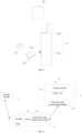
- FIG. 1is a structural schematic view of an aerosol generating device according to a first embodiment of the present disclosure
- FIG. 2is another structural schematic view of the aerosol generating device according to a first embodiment of the present disclosure
- a left half portion of FIG. 2represents an overall schematic view of the aerosol generating device 10.
- a right half portion of FIG. 2represents an explosive view of the aerosol generating device 10.
- the aerosol generating device 10includes a body 11, a heating assembly 12, and a storage assembly 13 (not shown in FIG. 2 ).
- the body 11 and the heating assembly 12are detachably connected.
- the body 11 and the storage assembly 13are detachably connected.
- the body 11includes a first body portion 11a and a second body portion 11b.
- the first body portion 11ais configured to receive a battery.
- the second body portion 11bis configured to receive a controller, a storage assembly, and so on.
- the second body portion 11bis configured to connect to the heating assembly 12.
- the second body portion 11bis arranged with a first connection member
- the heating assembly 12is arranged with a second connection member.
- the first connection member and the second connection memberare configured to allow the second body portion 11b to be connected to the heating assembly 12.
- the connection membermay be a snap, a screw, or the like.
- the heating assembly 12may be connected to the first body portion 11a through a bottom of the heating assembly 12.
- the aerosol generating device 10further includes a first cover 14 and a second cover 15 that are detachably connected to the body 11.
- the first cover 14may cover the heating assembly 12 to protect the heating assembly 12.
- the second cover 15may cover the heating assembly 12 (or the first cover 14) and the second body portion 11b to protect the heating assembly 12 and the second body portion 11b.
- the heating assembly 12is detachably connected to the body 11.
- the storage assembly 13stores a feature parameter.
- the feature parametercorresponds to one model of the heating assembly 12.
- the body 11is configured to obtain the feature parameter from the storage assembly 13, and heat the heating assembly 12 based on the feature parameter, such that the heating assembly 12 is taken to heat the aerosol generating substrate to generate the aerosol.
- the body 11includes a housing assembly and a controller received inside the housing assembly.
- the heating assembly 12 and the storage assembly 13are detachably connected to the housing assembly.
- the heating assembly 12 and the storage assembly 13are electrically connected to the controller.
- the controlleris configured to obtain the feature parameter from the storage assembly 13 and to heat the heating assembly 12 based on the feature parameter, allowing the heating assembly 12 to heat the aerosol generating substrate to generate the aerosol.
- the storage assembly 13stores the feature parameter, and the feature parameter corresponds to one model of the heating assembly 12. Since the feature parameter is fixed, the heating assembly 12 matching with the feature parameter may be heated only based on the feature parameter. In this way, when a model of a connected heating assembly 12 does not match the model corresponding to the feature parameter, the connected heating assembly 12 may not heat the aerosol generating substrate properly, such that a taste of the aerosol to be inhaled may be unsatisfying. In this way, randomly changing the model of the heating assembly 12 may be avoided. When the user replaces the heating assembly 12, only the heating assembly 12 in a same model may be replaced.
- the feature parameterincludes a parameter of a heating body in the heating assembly 12 and a heating parameter.
- the parameter of the heating bodyindicates correspondence between a resistance value of the heating body and a temperature of the heating body.
- the parameter of the heating bodymay be formed based on various models of heating assemblies 12.
- Material of the heating body, a process of manufacturing the heating body, a device for manufacturing the heating body and other factorscauses feature parameters (such as a temperature T - resistance R curve, an initial resistance value R0, a temperature coefficient of resistance (TCR), and so on) of various models of heating bodies to be various.
- feature parameterssuch as a temperature T - resistance R curve, an initial resistance value R0, a temperature coefficient of resistance (TCR), and so on
- the heating assembly 12may be placed in a test device, and feature parameters of the various models of the heating assemblies 12 may be tested.
- the heating parametermay be a "temperature-time variation curve", configured to determine that the heating body is heated in various extent as time passes. As shown in FIG. 3 , a schematic view of a temperature-time variation curve according to an embodiment of the present disclosure is shown.
- the controllermay control the temperature of the heating body based on a preset temperature-time curve and by applying a PID algorithm.
- the "temperature-time" curverefers to a heating curve of tobacco.
- the body 11When the user uses an electronic cigarette device for smoking, the body 11 may be connected to the heating assembly 12 firstly. For example, a switch button arranged on the body 11 may be switched on. In this way, the electronic cigarette device starts to operate.
- the body 11obtains the feature parameter in the storage component 13, obtains correspondence between the resistance value and the temperature of the heating body in the heating assembly 12, and starts timing. Subsequently, a current resistance value of the heating body may be obtained, and a current temperature may be obtained based on the parameter of the heating body. Finally, a voltage of the heating body may be controlled based on the "temperature-time" curve.
- a temperature required to heat the aerosol generating substratemay be variable in various time periods.
- a horizontal axisindicates the time
- a vertical axisindicates the temperature.
- the heating bodymay be heated, and a temperature of the heating body rises from a room temperature W0 to a temperature W1.
- the temperature of the heating bodymay be reduced, and the temperature of the heating body decreases from the temperature W1 to a temperature W2.
- the temperature of the heating bodyis reduced, and the temperature of the heating body decreases from the temperature W2 to the room temperature.
- a value of the T1may be 5s to 10s
- a value of the T2may be 12s to 18s
- a value of the W1may be 320°C to 360°C
- a value of the W2may be 300°C to 340°C.
- T17s
- T215s
- W1340°C
- W2320°C.
- the resistance of the heating bodydecreases by 2.28mQ accordingly. Therefore, when the temperature of the heating body decreases from the temperature W1 to the temperature W2, i.e., decreases by 20°C, the resistance value of the heating body needs to be decreased by 20*2.28mQ.
- FIG. 4is a schematic view of a pulse voltage according to the present disclosure. For example, in a time period t1, an enable switch may be switched on, and the battery may provide electrical energy to the heating body. In a time period t2, an enable switch may be switched off, and the battery may not provide electrical energy to the heating body.
- a percentage of the time period t1 over the time period Tmay be adjusted to further adjust the temperature of the heating body.
- the temperature of the heating bodymay be increased, and when the duty cycle of the time period t1 is decreased, the temperature of the heating body may be decreased.
- the storage assembly 13stores the feature parameter and an anti-counterfeiting parameter.
- the feature parameter and the anti-counterfeiting parametercorrespond to one model of heating assembly 12.
- the body 11may obtain a first anti-counterfeiting parameter from the heating assembly 12 and obtain a second anti-counterfeiting parameter and the feature parameter from the storage assembly 13.
- the controllerdetermines whether the first anti-counterfeiting parameter and the second anti-counterfeiting parameter are valid, whether the first anti-counterfeiting parameter and the second anti-counterfeiting parameter refer to a same model.
- the heating assembly 12may be heated by taking the feature parameter.
- the body 11, the heating assembly 12 and the storage assembly 13may be sold as a whole, or one or two of the main body 11, the heating assembly 12 and the storage assembly 13 may be sold in combination.
- the usermay replace any of the components easily.
- the userpurchases the device for a first time
- the userpurchases the body 11, the heating assembly 12 and the storage assembly 13 at the same time (correspondence between the model of the heating assembly 12 and the model of the storage assembly 13 needs to be aware).
- a heating assembly 12 in a model same as the previous modelmay be purchased only.
- the heating component 12may not operate properly since the feature parameter stored in the storage assembly 13 remains unchanged.
- the heating assembly 12 and the storage assembly 13may be sold in combination with each other.
- an adapted storage assembly 13such as a memory card
- the aerosol generating devicemay be used normally.
- the memory cardmay be a SIM card, a secure digital memory card (SD card), a multimedia card (MMC card), a nano memory card (NM card), and the like.
- FIG. 5is a structural schematic view of the body and the memory card according to an embodiment of the present disclosure.
- the body 11defines a tray receiving cavity 11c and includes a card tray 11d.
- the card tray 11dmay be received in the tray receiving cavity 11c.
- the card tray 11dmay be configured to hold a memory card.
- the memory cardis electrically connected to the controller inside the body 11.
- the aerosol generating deviceincludes: a body; a heating assembly, detachably connected to the body; and a storage assembly, detachably connected to the body.
- the storage assemblystores a feature parameter, and the feature parameter corresponds to one model of the heating assembly.
- the bodyis configured to obtain the feature parameter from the storage assembly and to heat the heating assembly based on the feature parameter, allowing the heating assembly to heat the aerosol generating substrate to generate the aerosol.
- both the heating assembly and the storage assemblyare configured as detachable assemblies, and the feature parameter stored in the storage assembly may be in one-to-one correspondence with the heating assembly.
- components of the aerosol generating devicemay be replaced easily, and the usage cost may be reduced.
- counterfeit or poor quality componentsmay be avoided, such that usage experience may not be affected.
- FIG. 6is a structural schematic view of an aerosol generating device according to a second embodiment of the present disclosure.
- the aerosol generating device 10includes a body 11, a heating assembly 12 and a storage assembly 13 (not shown in Figure 2 ).
- the body 11 and the heating assembly 12are detachably connected, and the body and the storage assembly 13 are detachably connected.
- the storage assembly 13includes a first short-range communication module 131 and a memory card 132.
- the body 11includes a controller 111 and a second short-range communication module 112 connected to the controller 111.
- the first short-range communication module 131 and the second short-range communication module 112may communicate with each other in a short distance for transmitting the feature parameter.
- the first short-range communication module 131 and the second short-range communication module 112may be any one of a WIFI communication module, a Bluetooth communication module, or a near-field communication (NFC) module.
- a WIFI communication modulea Bluetooth communication module
- NFCnear-field communication
- the storage component 13further stores anti-counterfeiting data.
- the feature parameter and the anti-counterfeiting dataform a data packet by performing a preset encryption algorithm.
- the controller 111is further configured to decrypt the data packet by a decryption algorithm corresponding to the preset encryption algorithm to obtain the feature parameter and the anti-counterfeiting data, and configured to verify the anti-counterfeiting data.
- a built-in encryption unitmay be configured in the storage assembly 13, and the controller 111 of the body 11 may be arranged with a corresponding decryption unit.
- the encryption unitfirstly encrypts the "anti-counterfeiting data" and transmits the encrypted data to the controller 111 of the body 11.
- the controller 111 of the body 11decrypts the data and determines the data to be consistent, the storage assembly 13 transmits the feature parameter to the controller 111.
- FIG. 7is a structural schematic view of the aerosol generating device according to a third embodiment of the present disclosure.
- the aerosol generating device 10includes a body 11, a heating assembly 12 and a storage assembly 13.
- the main body 11 and the heating assembly 12are detachably connected, and the body 11 and the storage assembly 13 are detachably connected.
- the heating assembly 12includes a first conductive terminal 121.
- the body 11includes a controller 111 and a second conductive terminal 113 connected to the controller 111.
- the body 11may supply power to the heating assembly 12.
- the heating assembly 12includes a heating body, and the body 11 is specifically configured to supply power to the heating body.
- FIG. 8is a structural schematic view of the heating assembly according to an embodiment of the present disclosure.
- the heating assembly 12includes a first conductive terminal 121 and a heating body 122.
- the heating assembly 12is configured to be detachably connected to the body of the aerosol generating device.
- the first conductive terminal 121is electrically connected to the second conductive terminal of the body.
- the aerosol generating devicefurther includes a storage assembly detachably connected to the body.
- the storage assemblystores the feature parameter.
- the feature parametercorresponds to one model of heating assembly 12.
- the bodyis configured to obtain the feature parameter from the storage assembly, and to heat the heating assembly based on the feature parameter, allowing the heating assembly to heat the aerosol generating substrate to generate the aerosol.
- FIG. 9is a structural schematic view of the storage assembly according to an embodiment of the present disclosure.
- the storage assembly 13includes a first short-range communication module 131 and a storage medium 132.
- the storage assembly 13is detachably connected to the body of the aerosol generating device. Data interaction may be achieved between the first short-range communication module 131 and the second short-range communication module of the body.
- the aerosol generating devicefurther includes the heating assembly detachably connected to the body.
- the storage medium 132stores the feature parameter.
- the feature parametercorresponds to one model of heating assembly.
- the bodyis configured to obtain the feature parameter from the storage medium 132, and to heat the heating assembly based on the feature parameter, allowing the heating assembly to heat the aerosol generating substrate to generate the aerosol.
Landscapes
- Engineering & Computer Science (AREA)
- Computer Networks & Wireless Communication (AREA)
- Control Of Resistance Heating (AREA)
Description
- The present disclosure relates to the field of heating without combustion, and in particular to an aerosol generating device, a heating assembly and a storage assembly.
- Most of the aerosol generating devices that involve heating without combustion in the art may take heating elements to heat aerosol generating substrates, generating a continuous fuming effect, such that a user may inhale the aerosol. After inhaling, the user may pull the aerosol generating substrate out of the heating element, allowing the heating element to be separated from the aerosol generating substrate.
- Since heating the aerosol generating substrate may generate a certain amount of adhesive substance, the adhesive substance may adhere to the heating element, forming an adhesive state, and the adhesive substance may remain on a surface of the heating element, such that an outer diameter of the heating element may increase, being harmful to the heating element to some extent. In this way, a taste of the aerosol may be affected, and a service life of the aerosol generating device that involves heating without combustion may be reduced.
- Aerosol generating devices of the prior art are described in
US2017/258136A1 ,WO2019/153642A1 andWO2019/162157A1 ; whereinUS2017/258136A1 describes a device according to the preamble of thepresent claim 1. - To solve the above problem, the present disclosure provides an aerosol generating device, a heating assembly and a storage assembly. On the one hand, the heating assembly and the storage assembly may be replaced easily, and a usage cost may be reduced. On the other hand, while replacing components of the device, counterfeit or poor quality components may be avoided, such that usage experience may not be affected.
- According to the invention, as defined in
claim 1, an aerosol generating device is provided and includes: a body; a heating assembly, detachably connected to the body; a storage assembly, detachably connected to the body. The storage assembly is configured to store a feature parameter, the feature parameter corresponds to one model of the heating assembly, the body is configured to obtain the feature parameter from the storage assembly and to heat the heating assembly based on the feature parameter, allowing the heating assembly to heat an aerosol generating substrate to generate an aerosol. - In some embodiments, the body includes: a housing assembly; and a controller, received inside the housing assembly. The heating assembly and the storage assembly are detachably connected to the housing assembly. When the heating assembly and the storage assembly are connected to the housing assembly, the heating assembly and the storage assembly are electrically connected to the controller. The controller is configured to obtain the feature parameter from the storage assembly.
- In some embodiments, the storage assembly is a memory card, the housing assembly includes a card tray, the memory card is connected to the card tray by plugging. The card tray is arranged with a first contact terminal, the first contact terminal is connected to the controller. The memory card is arranged with a second contact terminal, and when the memory card is plugged into the card tray, the first contact terminal is electrically connected to the second contact terminal.
- In some embodiments, the storage assembly is arranged with a first short-range communication module. The body is arranged with a second short-range communication module. The second short-range communication module of the body is configured to perform data interaction with the first short-range communication module of the storage assembly to obtain the feature parameter from the storage assembly.
- In some embodiments, each of the first short-range communication module and the second short-range communication module is any one of a Wi-Fi communication module, a Bluetooth communication module, and a near-field communication module.
- In some embodiments, the storage assembly is configured to store anti-counterfeiting data, the feature parameter and the anti-counterfeiting data form a data packet by setting an encryption algorithm. The controller is further configured to decrypt the data packet by performing a corresponding decryption algorithm to obtain the feature parameter and the anti-counterfeiting data, and configured to verify the anti-counterfeiting data.
- In some embodiments, the heating assembly includes: a heating body; and a first conductive terminal, connected to the heating body. The body further comprises a second conductive terminal. The body is configured to supply power to the heating body when the first conductive terminal is connected to the second conductive terminal.
- According to the invention, the feature parameter comprises a parameter of a heating body of the heating assembly and a heating parameter of the heating assembly, the parameter of the heating body indicates correspondence between a resistance value of the heating body and a temperature of the heating body. The body is further configured to: detect the resistance value of the heating body, determine the temperature of the heating body based on the parameter of the heating body, and heat the heating assembly based on the temperature of the heating body and the heating parameter.
- According to another aspect of the present disclosure, a heating assembly is provided and is configured to be detachably connected to a body of an aerosol generating device. The aerosol generating device further comprises a storage assembly detachably connected to the body. The storage assembly is configured to store a feature parameter, the feature parameter corresponds to one model of the heating assembly, the body is configured to obtain the feature parameter from the storage assembly and to heat the heating assembly based on the feature parameter, allowing the heating assembly to heat an aerosol generating substrate to generate an aerosol.
- According to still another aspect of the present disclosure, a storage assembly is provided and is configured to be detachably connected to a body of an aerosol generating device. The aerosol generating device further comprises a heating assembly detachably connected to the body. The storage assembly is configured to store a feature parameter, the feature parameter corresponds to one model of the heating assembly, the body is configured to obtain the feature parameter from the storage assembly and to heat the heating assembly based on the feature parameter, allowing the heating assembly to heat an aerosol generating substrate to generate an aerosol.
- According to the present disclosure, the aerosol generating device includes: a body; a heating assembly, detachably connected to the body; and a storage assembly, detachably connected to the body. The storage assembly stores a feature parameter, and the feature parameter corresponds to one model of the heating assembly. The body is configured to obtain the feature parameter from the storage assembly and to heat the heating assembly based on the feature parameter, allowing the heating assembly to heat the aerosol generating substrate to generate the aerosol. In this way, both the heating assembly and the storage assembly are configured as detachable assemblies, and the feature parameter stored in the storage assembly may be in one-to-one correspondence with the heating assembly. On the one hand, components of the aerosol generating device may be replaced easily, and the usage cost may be reduced. On the other hand, while replacing components of the device, counterfeit or poor quality components may be avoided, such that usage experience may not be affected.
- In order to more clearly illustrate technical solutions of embodiments of the present disclosure, the accompanying drawings for the embodiments will be briefly described in the following. Obviously, the drawings in the following show only some of the embodiments of the present disclosure. Any ordinary skilled person in the art may obtain other drawings based on these drawings without any creative work.
FIG. 1 is a structural schematic view of an aerosol generating device according to a first embodiment of the present disclosure.FIG. 2 is another structural schematic view of an aerosol generating device according to a first embodiment of the present disclosure.FIG. 3 is a schematic view of a temperature-time variation curve according to an embodiment of the present disclosure.FIG. 4 is a schematic view of a pulse voltage according to an embodiment of the present disclosure.FIG. 5 is a structural schematic view of a body and a memory card according to an embodiment of the present disclosure.FIG. 6 is a structural schematic view of an aerosol generating device according to a second embodiment of the present disclosure.FIG. 7 is a structural schematic view of an aerosol generating device according to a third embodiment of the present disclosure.FIG. 8 is a structural schematic view of a heating assembly according to an embodiment of the present disclosure.FIG. 9 is a structural schematic view of a storage assembly according to an embodiment of the present disclosure.- Technical solutions in the embodiments of the present disclosure will be clearly and completely described below by referring to the accompanying drawings in the embodiments of the present disclosure. It shall be understood that the embodiments described in detail herein only show components relevant to the present disclosure, instead of all components of the device. All other embodiments obtained by an ordinary skilled person in the art based on the embodiments in the present disclosure without making creative work shall fall within the scope of the present disclosure.
- Terms "first", "second", and the like, in the present disclosure are used to distinguish various objects and are not used to describe a particular order. In addition, terms "includes", "has" and any variations thereof are intended to cover non-exclusive inclusion. For example, a process, a method, a system, a product, or an apparatus that includes a series of operations or units is not limited to the listed operations or units, but optionally includes operations or units that are not listed, or optionally includes other operations or units that are inherent to the process, the method, the product, or the apparatus.
- The term "embodiments" herein means that a particular feature, a structure, or a property described in an embodiment may be included in at least one embodiment of the present disclosure. Presence of the term at various sections in the specification does not necessarily mean one same embodiment or a separate or an alternative embodiment that is mutually exclusive with other embodiments. The skilled person in the art shall understand explicitly and implicitly that the embodiments described herein may be combined with other embodiments.
- As shown in
FIGS. 1 and 2, FIG. 1 is a structural schematic view of an aerosol generating device according to a first embodiment of the present disclosure, andFIG. 2 is another structural schematic view of the aerosol generating device according to a first embodiment of the present disclosure. A left half portion ofFIG. 2 represents an overall schematic view of theaerosol generating device 10. A right half portion ofFIG. 2 represents an explosive view of theaerosol generating device 10. Theaerosol generating device 10 includes abody 11, aheating assembly 12, and a storage assembly 13 (not shown inFIG. 2 ). Thebody 11 and theheating assembly 12 are detachably connected. Thebody 11 and thestorage assembly 13 are detachably connected. - In an embodiment, in detail, the
body 11 includes afirst body portion 11a and asecond body portion 11b. Thefirst body portion 11a is configured to receive a battery. Thesecond body portion 11b is configured to receive a controller, a storage assembly, and so on. Thesecond body portion 11b is configured to connect to theheating assembly 12. For example, thesecond body portion 11b is arranged with a first connection member, and theheating assembly 12 is arranged with a second connection member. The first connection member and the second connection member are configured to allow thesecond body portion 11b to be connected to theheating assembly 12. In an embodiment, the connection member may be a snap, a screw, or the like. In addition, theheating assembly 12 may be connected to thefirst body portion 11a through a bottom of theheating assembly 12. - In an embodiment, the
aerosol generating device 10 further includes afirst cover 14 and asecond cover 15 that are detachably connected to thebody 11. When theheating assembly 12 is fixedly connected to thebody 11, thefirst cover 14 may cover theheating assembly 12 to protect theheating assembly 12. Further, thesecond cover 15 may cover the heating assembly 12 (or the first cover 14) and thesecond body portion 11b to protect theheating assembly 12 and thesecond body portion 11b. - In the present disclosure, the
heating assembly 12 is detachably connected to thebody 11. Thestorage assembly 13 stores a feature parameter. The feature parameter corresponds to one model of theheating assembly 12. Thebody 11 is configured to obtain the feature parameter from thestorage assembly 13, and heat theheating assembly 12 based on the feature parameter, such that theheating assembly 12 is taken to heat the aerosol generating substrate to generate the aerosol. - Further, in detail, the
body 11 includes a housing assembly and a controller received inside the housing assembly. Theheating assembly 12 and thestorage assembly 13 are detachably connected to the housing assembly. When theheating assembly 12 and thestorage assembly 13 are connected to the housing assembly, theheating assembly 12 and thestorage assembly 13 are electrically connected to the controller. The controller is configured to obtain the feature parameter from thestorage assembly 13 and to heat theheating assembly 12 based on the feature parameter, allowing theheating assembly 12 to heat the aerosol generating substrate to generate the aerosol. - In an embodiment, the
storage assembly 13 stores the feature parameter, and the feature parameter corresponds to one model of theheating assembly 12. Since the feature parameter is fixed, theheating assembly 12 matching with the feature parameter may be heated only based on the feature parameter. In this way, when a model of aconnected heating assembly 12 does not match the model corresponding to the feature parameter, theconnected heating assembly 12 may not heat the aerosol generating substrate properly, such that a taste of the aerosol to be inhaled may be unsatisfying. In this way, randomly changing the model of theheating assembly 12 may be avoided. When the user replaces theheating assembly 12, only theheating assembly 12 in a same model may be replaced. - In an embodiment, the feature parameter includes a parameter of a heating body in the
heating assembly 12 and a heating parameter. The parameter of the heating body indicates correspondence between a resistance value of the heating body and a temperature of the heating body. - The parameter of the heating body may be formed based on various models of
heating assemblies 12. Material of the heating body, a process of manufacturing the heating body, a device for manufacturing the heating body and other factors causes feature parameters (such as a temperature T - resistance R curve, an initial resistance value R0, a temperature coefficient of resistance (TCR), and so on) of various models of heating bodies to be various. While manufacturing the product, theheating assembly 12 may be placed in a test device, and feature parameters of the various models of theheating assemblies 12 may be tested. - The heating parameter may be a "temperature-time variation curve", configured to determine that the heating body is heated in various extent as time passes. As shown in
FIG. 3 , a schematic view of a temperature-time variation curve according to an embodiment of the present disclosure is shown. - For example, the controller may control the temperature of the heating body based on a preset temperature-time curve and by applying a PID algorithm. The "temperature-time" curve refers to a heating curve of tobacco.
- A specific scenario will be described in the following to illustrate the present embodiment.
- When the user uses an electronic cigarette device for smoking, the
body 11 may be connected to theheating assembly 12 firstly. For example, a switch button arranged on thebody 11 may be switched on. In this way, the electronic cigarette device starts to operate. - The
body 11 obtains the feature parameter in thestorage component 13, obtains correspondence between the resistance value and the temperature of the heating body in theheating assembly 12, and starts timing. Subsequently, a current resistance value of the heating body may be obtained, and a current temperature may be obtained based on the parameter of the heating body. Finally, a voltage of the heating body may be controlled based on the "temperature-time" curve. - It shall be understood that, generally, in order to obtain a better taste by heating the aerosol generating substrate (such as tobacco), a temperature required to heat the aerosol generating substrate may be variable in various time periods. In an embodiment, as shown in
FIG. 3 , a horizontal axis indicates the time, and a vertical axis indicates the temperature. - In a time period T0-T1, the heating body may be heated, and a temperature of the heating body rises from a room temperature W0 to a temperature W1.
- In a time period T1-T2, the temperature of the heating body remains at the temperature W1.
- In a time period T2-T3, the temperature of the heating body may be reduced, and the temperature of the heating body decreases from the temperature W1 to a temperature W2.
- In a time period T3-T4, the temperature of the heating body remains at the temperature W2.
- After the time point T4, the temperature of the heating body is reduced, and the temperature of the heating body decreases from the temperature W2 to the room temperature.
- In an embodiment, a value of the T1 may be 5s to 10s, a value of the T2 may be 12s to 18s, a value of the W1 may be 320°C to 360°C, and a value of the W2 may be 300°C to 340°C.
- In an embodiment, T1=7s, T2=15s, W1=340°C, and W2=320°C. In this case, when the temperature of the heating body decreases by 1°C, the resistance of the heating body decreases by 2.28mQ accordingly. Therefore, when the temperature of the heating body decreases from the temperature W1 to the temperature W2, i.e., decreases by 20°C, the resistance value of the heating body needs to be decreased by 20*2.28mQ.
- Further, while taking electrical energy to control the temperature for heating the heating body, a pulse frequency and/or a pulse amplitude and/or a duty cycle of the electrical energy supplied to the heating body may be variable to control the temperature of the heating body. In this way, the aerosol generating device may be controlled to release an aerosol having a better taste. As shown in
FIG. 4, FIG. 4 is a schematic view of a pulse voltage according to the present disclosure. For example, in a time period t1, an enable switch may be switched on, and the battery may provide electrical energy to the heating body. In a time period t2, an enable switch may be switched off, and the battery may not provide electrical energy to the heating body. Therefore, a percentage of the time period t1 over the time period T may be adjusted to further adjust the temperature of the heating body. In detail, when the duty cycle of the time period t1 is increased, the temperature of the heating body may be increased, and when the duty cycle of the time period t1 is decreased, the temperature of the heating body may be decreased. - In another embodiment, the
storage assembly 13 stores the feature parameter and an anti-counterfeiting parameter. The feature parameter and the anti-counterfeiting parameter correspond to one model ofheating assembly 12. When thebody 11 is connected to oneheating assembly 12 and onestorage assembly 13, thebody 11 may obtain a first anti-counterfeiting parameter from theheating assembly 12 and obtain a second anti-counterfeiting parameter and the feature parameter from thestorage assembly 13. The controller determines whether the first anti-counterfeiting parameter and the second anti-counterfeiting parameter are valid, whether the first anti-counterfeiting parameter and the second anti-counterfeiting parameter refer to a same model. When the first anti-counterfeiting parameter and the second anti-counterfeiting parameter are determined to be valid, and when the first anti-counterfeiting parameter and the second anti-counterfeiting parameter are determined as referring to the same model, theheating assembly 12 may be heated by taking the feature parameter. - Practically, the
body 11, theheating assembly 12 and thestorage assembly 13 may be sold as a whole, or one or two of themain body 11, theheating assembly 12 and thestorage assembly 13 may be sold in combination. In this way, the user may replace any of the components easily. For example, when the user purchases the device for a first time, the user purchases thebody 11, theheating assembly 12 and thestorage assembly 13 at the same time (correspondence between the model of theheating assembly 12 and the model of thestorage assembly 13 needs to be aware). While using, when theheating assembly 12 is worn out and needs to be replaced, aheating assembly 12 in a model same as the previous model may be purchased only. To be noted that, when the user purchases aheating component 12 with a model different from the previous one, theheating component 12 may not operate properly since the feature parameter stored in thestorage assembly 13 remains unchanged. - In addition, since the model of the
heating assembly 12 must correspond to the model indicated by thestorage assembly 13, theheating assembly 12 and thestorage assembly 13 may be sold in combination with each other. For example, when purchasing theheating component 12, an adapted storage assembly 13 (such as a memory card) may be included, ensuring the aerosol generating device to be used normally. - In an embodiment, the memory card may be a SIM card, a secure digital memory card (SD card), a multimedia card (MMC card), a nano memory card (NM card), and the like.
- As shown in
FIG. 5, FIG. 5 is a structural schematic view of the body and the memory card according to an embodiment of the present disclosure. Thebody 11 defines atray receiving cavity 11c and includes acard tray 11d. Thecard tray 11d may be received in thetray receiving cavity 11c. Thecard tray 11d may be configured to hold a memory card. When thecard tray 11d is received in thetray receiving cavity 11c, the memory card is electrically connected to the controller inside thebody 11. - According to the present disclosure, the aerosol generating device includes: a body; a heating assembly, detachably connected to the body; and a storage assembly, detachably connected to the body. The storage assembly stores a feature parameter, and the feature parameter corresponds to one model of the heating assembly. The body is configured to obtain the feature parameter from the storage assembly and to heat the heating assembly based on the feature parameter, allowing the heating assembly to heat the aerosol generating substrate to generate the aerosol. In this way, both the heating assembly and the storage assembly are configured as detachable assemblies, and the feature parameter stored in the storage assembly may be in one-to-one correspondence with the heating assembly. On the one hand, components of the aerosol generating device may be replaced easily, and the usage cost may be reduced. On the other hand, while replacing components of the device, counterfeit or poor quality components may be avoided, such that usage experience may not be affected.
- As shown in
FIG. 6, FIG. 6 is a structural schematic view of an aerosol generating device according to a second embodiment of the present disclosure. Theaerosol generating device 10 includes abody 11, aheating assembly 12 and a storage assembly 13 (not shown inFigure 2 ). Thebody 11 and theheating assembly 12 are detachably connected, and the body and thestorage assembly 13 are detachably connected. - In an embodiment, the
storage assembly 13 includes a first short-range communication module 131 and amemory card 132. Thebody 11 includes acontroller 111 and a second short-range communication module 112 connected to thecontroller 111. The first short-range communication module 131 and the second short-range communication module 112 may communicate with each other in a short distance for transmitting the feature parameter. - In an embodiment, the first short-
range communication module 131 and the second short-range communication module 112 may be any one of a WIFI communication module, a Bluetooth communication module, or a near-field communication (NFC) module. - In an embodiment, the
storage component 13 further stores anti-counterfeiting data. The feature parameter and the anti-counterfeiting data form a data packet by performing a preset encryption algorithm. Thecontroller 111 is further configured to decrypt the data packet by a decryption algorithm corresponding to the preset encryption algorithm to obtain the feature parameter and the anti-counterfeiting data, and configured to verify the anti-counterfeiting data. - For example, a built-in encryption unit may be configured in the
storage assembly 13, and thecontroller 111 of thebody 11 may be arranged with a corresponding decryption unit. When thestorage assembly 13 is successfully connected to thebody 11, the encryption unit firstly encrypts the "anti-counterfeiting data" and transmits the encrypted data to thecontroller 111 of thebody 11. When thecontroller 111 of thebody 11 decrypts the data and determines the data to be consistent, thestorage assembly 13 transmits the feature parameter to thecontroller 111. - As shown in
FIG. 7, FIG. 7 is a structural schematic view of the aerosol generating device according to a third embodiment of the present disclosure. Theaerosol generating device 10 includes abody 11, aheating assembly 12 and astorage assembly 13. Themain body 11 and theheating assembly 12 are detachably connected, and thebody 11 and thestorage assembly 13 are detachably connected. - In another embodiment, the
heating assembly 12 includes a firstconductive terminal 121. Thebody 11 includes acontroller 111 and a secondconductive terminal 113 connected to thecontroller 111. When the firstconductive terminal 121 is connected to the secondconductive terminal 113, thebody 11 may supply power to theheating assembly 12. Theheating assembly 12 includes a heating body, and thebody 11 is specifically configured to supply power to the heating body. - As shown in
FIG. 8, FIG. 8 is a structural schematic view of the heating assembly according to an embodiment of the present disclosure. Theheating assembly 12 includes a firstconductive terminal 121 and aheating body 122. Theheating assembly 12 is configured to be detachably connected to the body of the aerosol generating device. When theheating assembly 12 is connected to the body of the aerosol generating device, the firstconductive terminal 121 is electrically connected to the second conductive terminal of the body. The aerosol generating device further includes a storage assembly detachably connected to the body. - The storage assembly stores the feature parameter. The feature parameter corresponds to one model of
heating assembly 12. The body is configured to obtain the feature parameter from the storage assembly, and to heat the heating assembly based on the feature parameter, allowing the heating assembly to heat the aerosol generating substrate to generate the aerosol. - As shown in
FIG. 9, FIG. 9 is a structural schematic view of the storage assembly according to an embodiment of the present disclosure. Thestorage assembly 13 includes a first short-range communication module 131 and astorage medium 132. Thestorage assembly 13 is detachably connected to the body of the aerosol generating device. Data interaction may be achieved between the first short-range communication module 131 and the second short-range communication module of the body. The aerosol generating device further includes the heating assembly detachably connected to the body. - The
storage medium 132 stores the feature parameter. The feature parameter corresponds to one model of heating assembly. The body is configured to obtain the feature parameter from thestorage medium 132, and to heat the heating assembly based on the feature parameter, allowing the heating assembly to heat the aerosol generating substrate to generate the aerosol. - It shall be understood that structures and operation principles of the heating assembly and storage assembly in the above embodiments may be similar to those in the aerosol generating device embodiments, and will not be repeatedly described herein.
- The above description shows only implementations of the present disclosure, and does not limit the scope of the present disclosure. Any equivalent structure or equivalent process transformation made based on the specification and the accompanying drawings of the present disclosure, applied directly or indirectly in other related technical fields, shall be equivalently included in the scope of the present disclosure.
Claims (8)
- An aerosol generating device (10), comprising:a device body (11);a heating assembly (12), detachably connected to the device body (11);a storage assembly (13), detachably connected to the device body (11);wherein, the storage assembly (13) is configured to store a feature parameter, the feature parameter corresponds to one model of the heating assembly (12), the device body (11) is configured to obtain the feature parameter from the storage assembly (13) and to heat the heating assembly (12) based on the feature parameter, allowing the heating assembly (12) to heat an aerosol generating substrate to generate an aerosol; andthe aerosol generating device (10) ischaracterized in that,the feature parameter comprises a parameter of a heating body (122) of the heating assembly (12) and a heating parameter of the heating assembly (12), the parameter of the heating body (122) indicates correspondence between a resistance value of the heating body (122) and a temperature of the heating body (122); andthe device body (11) is further configured to: detect the resistance value of the heating body (122), determine the temperature of the heating body (122) based on the parameter of the heating body (122), and heat the heating assembly (12) based on the temperature of the heating body (122) and the heating parameter
- The aerosol generating device (10) according to claim 1, wherein,the device body (11) comprises:a housing assembly; anda controller (111), received inside the housing assembly; andthe heating assembly (12) and the storage assembly (13) are detachably connected to the housing assembly;when the heating assembly (12) and the storage assembly (13) are connected to the housing assembly, the heating assembly (12) and the storage assembly (13) are electrically connected to the controller (111); andthe controller (111) is configured to obtain the feature parameter from the storage assembly (13)
- The aerosol generating device (10) according to claim 2, wherein,the storage assembly (13) is a memory card, the housing assembly comprises a card tray (11d), the memory card is connected to the card tray (11d) by plugging;the card tray (11d) is arranged with a first contact terminal, the first contact terminal is connected to the controller (111);the memory card is arranged with a second contact terminal, and when the memory card is plugged into the card tray (11d), the first contact terminal is electrically connected to the second contact terminal.
- The aerosol generating device (10) according to claim 2, wherein,the storage assembly (13) comprises a memory card and a first short-range communication module (131);the device body (11) is arranged with a second short-range communication module (112);the second short-range communication module (112) of the device body (11) is configured to perform data interaction with the first short-range communication module (131) of the storage assembly (13) to obtain the feature parameter from the storage assembly (13).
- The aerosol generating device (10) according to claim 4, wherein,
each of the first short-range communication module (131) and the second short-range communication module (112) is any one of a Wi-Fi communication module, a Bluetooth communication module, and a near-field communication module. - The aerosol generating device (10) according to claim 2, wherein,the storage assembly (13) is configured to store anti-counterfeiting data, the feature parameter and the anti-counterfeiting data form a data packet by performing a preset encryption algorithm; andthe controller (111) is further configured to decrypt the data packet by performing a decryption algorithm corresponding to the preset encryption algorithm to obtain the feature parameter and the anti-counterfeiting data, and configured to verify the anti-counterfeiting data.
- The aerosol generating device (10) according to claim 1, wherein,the heating assembly (12) comprises: a first conductive terminal (121), connected to the heating body (122);the device body (11) further comprises a second conductive terminal (113); andthe device body (11) is configured to supply power to the heating body (122) when the first conductive terminal (121) is connected to the second conductive terminal (113).
- The aerosol generating device according to claim 1, wherein,the device body (11) is configured to heat the heating assembly (12) when the model of the heating assembly (12) matches a model indicated by the feature parameter of the storage assembly (13); andthe device body (11) is configured to not heat the heating assembly (12) when the model of the heating assembly (12) does not match a model indicated by the feature parameter of the storage assembly (13).
Applications Claiming Priority (2)
| Application Number | Priority Date | Filing Date | Title |
|---|---|---|---|
| CN201910829145.5ACN110584207B (en) | 2019-09-03 | 2019-09-03 | An aerosol generating device, a heating component and a storage component |
| PCT/CN2020/112618WO2021043106A1 (en) | 2019-09-03 | 2020-08-31 | Aerosol generating device, heating assembly and storage assembly |
Publications (3)
| Publication Number | Publication Date |
|---|---|
| EP4026444A1 EP4026444A1 (en) | 2022-07-13 |
| EP4026444A4 EP4026444A4 (en) | 2022-11-09 |
| EP4026444B1true EP4026444B1 (en) | 2023-09-20 |
Family
ID=68857184
Family Applications (1)
| Application Number | Title | Priority Date | Filing Date |
|---|---|---|---|
| EP20860661.6AActiveEP4026444B1 (en) | 2019-09-03 | 2020-08-31 | Aerosol generating device, heating assembly and related data storage |
Country Status (5)
| Country | Link |
|---|---|
| EP (1) | EP4026444B1 (en) |
| JP (1) | JP7397173B2 (en) |
| KR (1) | KR102728486B1 (en) |
| CN (1) | CN110584207B (en) |
| WO (1) | WO2021043106A1 (en) |
Families Citing this family (4)
| Publication number | Priority date | Publication date | Assignee | Title |
|---|---|---|---|---|
| CN110584207B (en)* | 2019-09-03 | 2025-02-21 | 深圳麦克韦尔科技有限公司 | An aerosol generating device, a heating component and a storage component |
| CN112790440A (en)* | 2020-12-25 | 2021-05-14 | 深圳市基克纳科技有限公司 | A kind of atomizer heating element replacement method, device and atomizer |
| CN113907422B (en)* | 2021-08-31 | 2024-07-05 | 深圳麦时科技有限公司 | Heating assembly, electronic atomizing device and control method of heating assembly |
| CN221813221U (en)* | 2023-12-11 | 2024-10-11 | 韩国烟草人参公社 | An aerosol generating device |
Family Cites Families (16)
| Publication number | Priority date | Publication date | Assignee | Title |
|---|---|---|---|---|
| US9597466B2 (en)* | 2014-03-12 | 2017-03-21 | R. J. Reynolds Tobacco Company | Aerosol delivery system and related method, apparatus, and computer program product for providing control information to an aerosol delivery device via a cartridge |
| US11696604B2 (en)* | 2014-03-13 | 2023-07-11 | Rai Strategic Holdings, Inc. | Aerosol delivery device and related method and computer program product for controlling an aerosol delivery device based on input characteristics |
| PL3750583T3 (en)* | 2014-10-14 | 2022-06-27 | Fontem Holdings 1 B.V. | Electronic smoking device and cartridge |
| WO2017096512A1 (en)* | 2015-12-07 | 2017-06-15 | 深圳麦克韦尔股份有限公司 | Electronic cigarette and heating and atomization control method therefor |
| US9936734B2 (en)* | 2016-03-11 | 2018-04-10 | Altria Client Services, Llc. | Personal carrying case for electronic vaping device |
| IL297612B2 (en)* | 2016-05-25 | 2024-06-01 | Juul Labs Inc | Control of an electronic evaporation device |
| DE102017104555B4 (en)* | 2017-03-06 | 2018-09-20 | Hauni Maschinenbau Gmbh | Evaporator unit for an inhaler |
| DE102017121664A1 (en)* | 2017-09-19 | 2019-03-21 | Hauni Maschinenbau Gmbh | Component part and base part for an inhaler, and method for manufacturing the same |
| WO2019082280A1 (en)* | 2017-10-24 | 2019-05-02 | 日本たばこ産業株式会社 | Aerosol generating device, method for controlling aerosol generating device, method for estimating remaining quantity of aerosol source or flavor source, and programs for causing processor to execute said methods |
| CN108338420B (en)* | 2018-02-09 | 2020-09-15 | 常州市派腾电子技术服务有限公司 | Heating wire identification device, method, electronic cigarette and computer storage medium |
| EP3758524A1 (en)* | 2018-02-26 | 2021-01-06 | Nerudia Limited | A smoking substitute device |
| CN208096016U (en)* | 2018-03-30 | 2018-11-16 | 上海新型烟草制品研究院有限公司 | A kind of aerosol generating device of replaceable heating component |
| CN109330027B (en)* | 2018-08-24 | 2022-10-21 | 深圳麦克韦尔科技有限公司 | Electronic smoking set, control method thereof, heating component, electronic equipment and storage medium |
| CN110584207B (en)* | 2019-09-03 | 2025-02-21 | 深圳麦克韦尔科技有限公司 | An aerosol generating device, a heating component and a storage component |
| CN211861800U (en)* | 2019-09-03 | 2020-11-06 | 深圳麦克韦尔科技有限公司 | Aerial fog generating device, heating component and storage component |
| CN110623305A (en)* | 2019-09-05 | 2019-12-31 | 深圳麦克韦尔科技有限公司 | An aerosol generating device, a heating component and a data interaction method |
- 2019
- 2019-09-03CNCN201910829145.5Apatent/CN110584207B/enactiveActive
- 2020
- 2020-08-31KRKR1020227008082Apatent/KR102728486B1/enactiveActive
- 2020-08-31EPEP20860661.6Apatent/EP4026444B1/enactiveActive
- 2020-08-31WOPCT/CN2020/112618patent/WO2021043106A1/ennot_activeCeased
- 2020-08-31JPJP2022513683Apatent/JP7397173B2/enactiveActive
Also Published As
| Publication number | Publication date |
|---|---|
| EP4026444A4 (en) | 2022-11-09 |
| EP4026444A1 (en) | 2022-07-13 |
| KR102728486B1 (en) | 2024-11-11 |
| JP7397173B2 (en) | 2023-12-12 |
| CN110584207B (en) | 2025-02-21 |
| CN110584207A (en) | 2019-12-20 |
| JP2022545963A (en) | 2022-11-01 |
| KR20220043210A (en) | 2022-04-05 |
| WO2021043106A1 (en) | 2021-03-11 |
Similar Documents
| Publication | Publication Date | Title |
|---|---|---|
| EP4026444B1 (en) | Aerosol generating device, heating assembly and related data storage | |
| US20210177054A1 (en) | Electronic smoking device and capsule system | |
| EP3818850B1 (en) | Aerosol generation system and operation method therefor | |
| KR102851267B1 (en) | Electronic aerosol provision system | |
| EP4026445A1 (en) | Aerosol generating device, heating assembly and data exchange method | |
| CN110477460B (en) | Electronic cigarette taste personalized setting method, device, equipment and storage medium | |
| JP2023534909A (en) | Cartridge for aerosol generating device with cartridge communication module | |
| KR20200144897A (en) | Aerosol generating apparatus and method for operating the same | |
| CN112545061A (en) | Temperature control method, electronic cigarette and atomization heating device | |
| CN119072256A (en) | Holder for an aerosol delivery device | |
| CN211861800U (en) | Aerial fog generating device, heating component and storage component | |
| JP2023553234A (en) | Cartridge and aerosol generator including the same | |
| CA3213183A1 (en) | Method and apparatus for generating aerosol based on cigarette type | |
| KR20230055184A (en) | Aerosol generating device and operating method thereof | |
| CN112493545A (en) | Electronic cigarette cartridge and electronic cigarette host | |
| US20240057686A1 (en) | Aerosol Generation Device Comprising a Communication Module, and Associated Communication System and Method | |
| US20240061922A1 (en) | Method and device for authenticating user | |
| KR102587922B1 (en) | Aerosol generating device and controlling method thereof | |
| US20240284990A1 (en) | Accessory for aerosol generating device and aerosol generating system including the same | |
| WO2025056541A2 (en) | Aerosol provision system | |
| WO2025062020A1 (en) | Aerosol provision device | |
| CN119679201A (en) | Aerosol supply system | |
| CA3217315A1 (en) | Method and apparatus for unlocking based on user input | |
| CN116963625A (en) | Power supply device and aerosol generating system including the same | |
| TW202434133A (en) | Aerosol provision device |
Legal Events
| Date | Code | Title | Description |
|---|---|---|---|
| STAA | Information on the status of an ep patent application or granted ep patent | Free format text:STATUS: THE INTERNATIONAL PUBLICATION HAS BEEN MADE | |
| PUAI | Public reference made under article 153(3) epc to a published international application that has entered the european phase | Free format text:ORIGINAL CODE: 0009012 | |
| STAA | Information on the status of an ep patent application or granted ep patent | Free format text:STATUS: REQUEST FOR EXAMINATION WAS MADE | |
| 17P | Request for examination filed | Effective date:20220403 | |
| AK | Designated contracting states | Kind code of ref document:A1 Designated state(s):AL AT BE BG CH CY CZ DE DK EE ES FI FR GB GR HR HU IE IS IT LI LT LU LV MC MK MT NL NO PL PT RO RS SE SI SK SM TR | |
| A4 | Supplementary search report drawn up and despatched | Effective date:20221010 | |
| RIC1 | Information provided on ipc code assigned before grant | Ipc:A24F 40/53 20200101ALI20221004BHEP Ipc:A24F 40/10 20200101ALI20221004BHEP Ipc:A24F 40/65 20200101ALI20221004BHEP Ipc:A24F 40/50 20200101ALI20221004BHEP Ipc:A24F 40/57 20200101AFI20221004BHEP | |
| DAV | Request for validation of the european patent (deleted) | ||
| DAX | Request for extension of the european patent (deleted) | ||
| REG | Reference to a national code | Ref country code:DE Ref legal event code:R079 Ref document number:602020018076 Country of ref document:DE Free format text:PREVIOUS MAIN CLASS: A24F0047000000 Ipc:A24F0040570000 Ref country code:DE Ref legal event code:R079 Free format text:PREVIOUS MAIN CLASS: A24F0047000000 Ipc:A24F0040570000 | |
| GRAP | Despatch of communication of intention to grant a patent | Free format text:ORIGINAL CODE: EPIDOSNIGR1 | |
| STAA | Information on the status of an ep patent application or granted ep patent | Free format text:STATUS: GRANT OF PATENT IS INTENDED | |
| RIC1 | Information provided on ipc code assigned before grant | Ipc:A24F 40/40 20200101ALN20230524BHEP Ipc:A24F 40/65 20200101ALI20230524BHEP Ipc:A24F 40/53 20200101ALI20230524BHEP Ipc:A24F 40/57 20200101AFI20230524BHEP | |
| INTG | Intention to grant announced | Effective date:20230628 | |
| GRAS | Grant fee paid | Free format text:ORIGINAL CODE: EPIDOSNIGR3 | |
| GRAA | (expected) grant | Free format text:ORIGINAL CODE: 0009210 | |
| STAA | Information on the status of an ep patent application or granted ep patent | Free format text:STATUS: THE PATENT HAS BEEN GRANTED | |
| P01 | Opt-out of the competence of the unified patent court (upc) registered | Effective date:20230802 | |
| AK | Designated contracting states | Kind code of ref document:B1 Designated state(s):AL AT BE BG CH CY CZ DE DK EE ES FI FR GB GR HR HU IE IS IT LI LT LU LV MC MK MT NL NO PL PT RO RS SE SI SK SM TR | |
| REG | Reference to a national code | Ref country code:GB Ref legal event code:FG4D | |
| REG | Reference to a national code | Ref country code:CH Ref legal event code:EP | |
| REG | Reference to a national code | Ref country code:IE Ref legal event code:FG4D | |
| REG | Reference to a national code | Ref country code:DE Ref legal event code:R096 Ref document number:602020018076 Country of ref document:DE | |
| REG | Reference to a national code | Ref country code:LT Ref legal event code:MG9D | |
| PG25 | Lapsed in a contracting state [announced via postgrant information from national office to epo] | Ref country code:GR Free format text:LAPSE BECAUSE OF FAILURE TO SUBMIT A TRANSLATION OF THE DESCRIPTION OR TO PAY THE FEE WITHIN THE PRESCRIBED TIME-LIMIT Effective date:20231221 | |
| REG | Reference to a national code | Ref country code:NL Ref legal event code:MP Effective date:20230920 | |
| PG25 | Lapsed in a contracting state [announced via postgrant information from national office to epo] | Ref country code:SE Free format text:LAPSE BECAUSE OF FAILURE TO SUBMIT A TRANSLATION OF THE DESCRIPTION OR TO PAY THE FEE WITHIN THE PRESCRIBED TIME-LIMIT Effective date:20230920 Ref country code:RS Free format text:LAPSE BECAUSE OF FAILURE TO SUBMIT A TRANSLATION OF THE DESCRIPTION OR TO PAY THE FEE WITHIN THE PRESCRIBED TIME-LIMIT Effective date:20230920 Ref country code:NO Free format text:LAPSE BECAUSE OF FAILURE TO SUBMIT A TRANSLATION OF THE DESCRIPTION OR TO PAY THE FEE WITHIN THE PRESCRIBED TIME-LIMIT Effective date:20231220 Ref country code:LV Free format text:LAPSE BECAUSE OF FAILURE TO SUBMIT A TRANSLATION OF THE DESCRIPTION OR TO PAY THE FEE WITHIN THE PRESCRIBED TIME-LIMIT Effective date:20230920 Ref country code:LT Free format text:LAPSE BECAUSE OF FAILURE TO SUBMIT A TRANSLATION OF THE DESCRIPTION OR TO PAY THE FEE WITHIN THE PRESCRIBED TIME-LIMIT Effective date:20230920 Ref country code:HR Free format text:LAPSE BECAUSE OF FAILURE TO SUBMIT A TRANSLATION OF THE DESCRIPTION OR TO PAY THE FEE WITHIN THE PRESCRIBED TIME-LIMIT Effective date:20230920 Ref country code:GR Free format text:LAPSE BECAUSE OF FAILURE TO SUBMIT A TRANSLATION OF THE DESCRIPTION OR TO PAY THE FEE WITHIN THE PRESCRIBED TIME-LIMIT Effective date:20231221 Ref country code:FI Free format text:LAPSE BECAUSE OF FAILURE TO SUBMIT A TRANSLATION OF THE DESCRIPTION OR TO PAY THE FEE WITHIN THE PRESCRIBED TIME-LIMIT Effective date:20230920 | |
| REG | Reference to a national code | Ref country code:AT Ref legal event code:MK05 Ref document number:1612685 Country of ref document:AT Kind code of ref document:T Effective date:20230920 | |
| PG25 | Lapsed in a contracting state [announced via postgrant information from national office to epo] | Ref country code:NL Free format text:LAPSE BECAUSE OF FAILURE TO SUBMIT A TRANSLATION OF THE DESCRIPTION OR TO PAY THE FEE WITHIN THE PRESCRIBED TIME-LIMIT Effective date:20230920 | |
| PG25 | Lapsed in a contracting state [announced via postgrant information from national office to epo] | Ref country code:IS Free format text:LAPSE BECAUSE OF FAILURE TO SUBMIT A TRANSLATION OF THE DESCRIPTION OR TO PAY THE FEE WITHIN THE PRESCRIBED TIME-LIMIT Effective date:20240120 | |
| PG25 | Lapsed in a contracting state [announced via postgrant information from national office to epo] | Ref country code:AT Free format text:LAPSE BECAUSE OF FAILURE TO SUBMIT A TRANSLATION OF THE DESCRIPTION OR TO PAY THE FEE WITHIN THE PRESCRIBED TIME-LIMIT Effective date:20230920 | |
| PG25 | Lapsed in a contracting state [announced via postgrant information from national office to epo] | Ref country code:ES Free format text:LAPSE BECAUSE OF FAILURE TO SUBMIT A TRANSLATION OF THE DESCRIPTION OR TO PAY THE FEE WITHIN THE PRESCRIBED TIME-LIMIT Effective date:20230920 | |
| PG25 | Lapsed in a contracting state [announced via postgrant information from national office to epo] | Ref country code:SM Free format text:LAPSE BECAUSE OF FAILURE TO SUBMIT A TRANSLATION OF THE DESCRIPTION OR TO PAY THE FEE WITHIN THE PRESCRIBED TIME-LIMIT Effective date:20230920 Ref country code:RO Free format text:LAPSE BECAUSE OF FAILURE TO SUBMIT A TRANSLATION OF THE DESCRIPTION OR TO PAY THE FEE WITHIN THE PRESCRIBED TIME-LIMIT Effective date:20230920 Ref country code:IS Free format text:LAPSE BECAUSE OF FAILURE TO SUBMIT A TRANSLATION OF THE DESCRIPTION OR TO PAY THE FEE WITHIN THE PRESCRIBED TIME-LIMIT Effective date:20240120 Ref country code:ES Free format text:LAPSE BECAUSE OF FAILURE TO SUBMIT A TRANSLATION OF THE DESCRIPTION OR TO PAY THE FEE WITHIN THE PRESCRIBED TIME-LIMIT Effective date:20230920 Ref country code:EE Free format text:LAPSE BECAUSE OF FAILURE TO SUBMIT A TRANSLATION OF THE DESCRIPTION OR TO PAY THE FEE WITHIN THE PRESCRIBED TIME-LIMIT Effective date:20230920 Ref country code:CZ Free format text:LAPSE BECAUSE OF FAILURE TO SUBMIT A TRANSLATION OF THE DESCRIPTION OR TO PAY THE FEE WITHIN THE PRESCRIBED TIME-LIMIT Effective date:20230920 Ref country code:AT Free format text:LAPSE BECAUSE OF FAILURE TO SUBMIT A TRANSLATION OF THE DESCRIPTION OR TO PAY THE FEE WITHIN THE PRESCRIBED TIME-LIMIT Effective date:20230920 Ref country code:PT Free format text:LAPSE BECAUSE OF FAILURE TO SUBMIT A TRANSLATION OF THE DESCRIPTION OR TO PAY THE FEE WITHIN THE PRESCRIBED TIME-LIMIT Effective date:20240122 Ref country code:SK Free format text:LAPSE BECAUSE OF FAILURE TO SUBMIT A TRANSLATION OF THE DESCRIPTION OR TO PAY THE FEE WITHIN THE PRESCRIBED TIME-LIMIT Effective date:20230920 | |
| PG25 | Lapsed in a contracting state [announced via postgrant information from national office to epo] | Ref country code:PL Free format text:LAPSE BECAUSE OF FAILURE TO SUBMIT A TRANSLATION OF THE DESCRIPTION OR TO PAY THE FEE WITHIN THE PRESCRIBED TIME-LIMIT Effective date:20230920 Ref country code:IT Free format text:LAPSE BECAUSE OF FAILURE TO SUBMIT A TRANSLATION OF THE DESCRIPTION OR TO PAY THE FEE WITHIN THE PRESCRIBED TIME-LIMIT Effective date:20230920 | |
| REG | Reference to a national code | Ref country code:DE Ref legal event code:R097 Ref document number:602020018076 Country of ref document:DE | |
| PG25 | Lapsed in a contracting state [announced via postgrant information from national office to epo] | Ref country code:DK Free format text:LAPSE BECAUSE OF FAILURE TO SUBMIT A TRANSLATION OF THE DESCRIPTION OR TO PAY THE FEE WITHIN THE PRESCRIBED TIME-LIMIT Effective date:20230920 | |
| PLBE | No opposition filed within time limit | Free format text:ORIGINAL CODE: 0009261 | |
| STAA | Information on the status of an ep patent application or granted ep patent | Free format text:STATUS: NO OPPOSITION FILED WITHIN TIME LIMIT | |
| PG25 | Lapsed in a contracting state [announced via postgrant information from national office to epo] | Ref country code:DK Free format text:LAPSE BECAUSE OF FAILURE TO SUBMIT A TRANSLATION OF THE DESCRIPTION OR TO PAY THE FEE WITHIN THE PRESCRIBED TIME-LIMIT Effective date:20230920 | |
| 26N | No opposition filed | Effective date:20240621 | |
| PGFP | Annual fee paid to national office [announced via postgrant information from national office to epo] | Ref country code:DE Payment date:20240806 Year of fee payment:5 | |
| PGFP | Annual fee paid to national office [announced via postgrant information from national office to epo] | Ref country code:GB Payment date:20240823 Year of fee payment:5 | |
| PG25 | Lapsed in a contracting state [announced via postgrant information from national office to epo] | Ref country code:SI Free format text:LAPSE BECAUSE OF FAILURE TO SUBMIT A TRANSLATION OF THE DESCRIPTION OR TO PAY THE FEE WITHIN THE PRESCRIBED TIME-LIMIT Effective date:20230920 | |
| PG25 | Lapsed in a contracting state [announced via postgrant information from national office to epo] | Ref country code:SI Free format text:LAPSE BECAUSE OF FAILURE TO SUBMIT A TRANSLATION OF THE DESCRIPTION OR TO PAY THE FEE WITHIN THE PRESCRIBED TIME-LIMIT Effective date:20230920 | |
| PG25 | Lapsed in a contracting state [announced via postgrant information from national office to epo] | Ref country code:BG Free format text:LAPSE BECAUSE OF FAILURE TO SUBMIT A TRANSLATION OF THE DESCRIPTION OR TO PAY THE FEE WITHIN THE PRESCRIBED TIME-LIMIT Effective date:20230920 | |
| PG25 | Lapsed in a contracting state [announced via postgrant information from national office to epo] | Ref country code:BG Free format text:LAPSE BECAUSE OF FAILURE TO SUBMIT A TRANSLATION OF THE DESCRIPTION OR TO PAY THE FEE WITHIN THE PRESCRIBED TIME-LIMIT Effective date:20230920 | |
| REG | Reference to a national code | Ref country code:CH Ref legal event code:PL | |
| PG25 | Lapsed in a contracting state [announced via postgrant information from national office to epo] | Ref country code:LU Free format text:LAPSE BECAUSE OF NON-PAYMENT OF DUE FEES Effective date:20240831 | |
| PG25 | Lapsed in a contracting state [announced via postgrant information from national office to epo] | Ref country code:CH Free format text:LAPSE BECAUSE OF NON-PAYMENT OF DUE FEES Effective date:20240831 Ref country code:MC Free format text:LAPSE BECAUSE OF FAILURE TO SUBMIT A TRANSLATION OF THE DESCRIPTION OR TO PAY THE FEE WITHIN THE PRESCRIBED TIME-LIMIT Effective date:20230920 | |
| REG | Reference to a national code | Ref country code:BE Ref legal event code:MM Effective date:20240831 | |
| PG25 | Lapsed in a contracting state [announced via postgrant information from national office to epo] | Ref country code:BE Free format text:LAPSE BECAUSE OF NON-PAYMENT OF DUE FEES Effective date:20240831 | |
| PG25 | Lapsed in a contracting state [announced via postgrant information from national office to epo] | Ref country code:FR Free format text:LAPSE BECAUSE OF NON-PAYMENT OF DUE FEES Effective date:20240831 | |
| PG25 | Lapsed in a contracting state [announced via postgrant information from national office to epo] | Ref country code:IE Free format text:LAPSE BECAUSE OF NON-PAYMENT OF DUE FEES Effective date:20240831 |