EP4024046B1 - Instrument for elemental analysis - Google Patents
Instrument for elemental analysisDownload PDFInfo
- Publication number
- EP4024046B1 EP4024046B1EP20857546.4AEP20857546AEP4024046B1EP 4024046 B1EP4024046 B1EP 4024046B1EP 20857546 AEP20857546 AEP 20857546AEP 4024046 B1EP4024046 B1EP 4024046B1
- Authority
- EP
- European Patent Office
- Prior art keywords
- combustion tube
- slider
- sample injection
- sample
- pressure
- Prior art date
- Legal status (The legal status is an assumption and is not a legal conclusion. Google has not performed a legal analysis and makes no representation as to the accuracy of the status listed.)
- Active
Links
Images


Classifications
- G—PHYSICS
- G01—MEASURING; TESTING
- G01N—INVESTIGATING OR ANALYSING MATERIALS BY DETERMINING THEIR CHEMICAL OR PHYSICAL PROPERTIES
- G01N31/00—Investigating or analysing non-biological materials by the use of the chemical methods specified in the subgroup; Apparatus specially adapted for such methods
- G01N31/12—Investigating or analysing non-biological materials by the use of the chemical methods specified in the subgroup; Apparatus specially adapted for such methods using combustion
- G—PHYSICS
- G01—MEASURING; TESTING
- G01N—INVESTIGATING OR ANALYSING MATERIALS BY DETERMINING THEIR CHEMICAL OR PHYSICAL PROPERTIES
- G01N31/00—Investigating or analysing non-biological materials by the use of the chemical methods specified in the subgroup; Apparatus specially adapted for such methods
- G01N31/10—Investigating or analysing non-biological materials by the use of the chemical methods specified in the subgroup; Apparatus specially adapted for such methods using catalysis
- G—PHYSICS
- G01—MEASURING; TESTING
- G01N—INVESTIGATING OR ANALYSING MATERIALS BY DETERMINING THEIR CHEMICAL OR PHYSICAL PROPERTIES
- G01N33/00—Investigating or analysing materials by specific methods not covered by groups G01N1/00 - G01N31/00
- G01N33/18—Water
- G01N33/1826—Organic contamination in water
- G01N33/1846—Total carbon analysis
Definitions
- the present inventionrelates to an instrument for elemental analysis.
- a combustion oxidation type total organic carbon measuring device(see Patent Document 1).
- the TOC meterheats a combustion tube in which an oxidation catalyst is arranged to a high temperature (for example, about 680°C) by an electric furnace, and supplies carrier gas to the combustion tube at a constant flow rate.
- a liquid sampleis injected into the combustion tube, a carbon component contained in the sample is converted to carbon dioxide by the action of the oxidation catalyst.
- a detectorsuch as an infrared carbon dioxide detector (NDIR) is connected to the combustion tube, and the carbon dioxide generated in the combustion tube is introduced to the detector together with the carrier gas so that the concentration of the carbon dioxide is measured.
- NDIRinfrared carbon dioxide detector
- Patent Document 2Other combustion-type water quality analysers (TOC meters) are disclosed in Patent Document 2 (discussed further below) and Patent Document 3.
- TOC meterscombustion-type water quality analysers
- Patent Document 3an abnormality such as gas leakage or clogging of the apparatus is detected by monitoring the time lag between sample injection, determined e.g. by a temperature or pressure sensor, and the signal peak of the instrument's carbon dioxide detector.
- the combustion tubeSince the combustion tube is arranged in the electric furnace, it is difficult to visually check such a failure from the outside, and when a measured value of zero or close to zero is obtained, it is difficult to determine whether the result is accurate or due to a failure of the combustion tube unless the combustion tube is taken out from the electric furnace and checked. If a fluid flow rate in a flow path connecting the combustion tube and the detector is monitored by a flow sensor, it is possible to detect an abnormality in a system between the combustion tube and the detector. However, installing such a flow sensor leads to an increase in device cost, which is not preferable.
- An object of the present inventionis to enable detection of an abnormality degree of a state in the system between the combustion tube and the detector without increasing device cost.
- sample injection mechanismfor injecting a sample into a combustion tube
- a mechanism for sliding a slider holding a nozzle for sample injection above the combustion tubesee Patent Document 2.
- the sample injection mechanismis switched between a state in which a sample injection port provided on the combustion tube is sealed and a state in which the nozzle for sample injection is positioned above the sample injection port by sliding the slider.
- an instrument for elemental analysisincludes a combustion tube that has a sample injection port with an open top and is for combusting a liquid sample in the inside, a sample injection mechanism having a nozzle and a slider, the nozzle being for injecting a sample into the combustion tube, and the slider being configured to slide between a first position and a second position above the combustion tube, sample injection mechanism being configured so that the sample injection port of the combustion tube is sealed in a state where the slider is positioned at the first position, and the sample injection port is unsealed and the nozzle is positioned above the sample injection port in a state where the slider is at the second position, a carrier gas supply flow path communicating with the inside of the combustion tube to supply carrier gas into the combustion tube, a pressure sensor that detects pressure in the carrier gas supply flow path, a detector for detecting components in sample gas flowing out of the combustion tube, and an arithmetic part
- determination on the abnormality degree of the state in the system between the combustion tube and the detectoris performed based on a pressure change in the combustion tube when the slider of the sample injection mechanism slides from the first position to the second position. Therefore, the abnormality in the system between the combustion tube and the detector can be detected without increasing the device cost.
- Fig. 1shows a schematic configuration of a combustion oxidation type TOC meter, which is one of instruments for elemental analysis.
- the TOC meter of the present embodimentmainly includes a combustion tube 2, an electric furnace 4, a sample injection mechanism 6, a switching valve 14, a syringe pump 16, a Dehumidifier 20, a detector 22, and a control device 44.
- the combustion tube 2is made from, for example, quartz glass, and an oxidation catalyst is arranged inside.
- the combustion tube 2is heated by the electric furnace 4 to a high temperature (for example, 680°C) and burns a liquid sample injected to the inside to generate sample gas.
- the combustion tube 2includes a sample injection port 3 with an open top.
- the sample injection mechanism 6is provided on the combustion tube 2.
- the sample injection mechanism 6holds a nozzle 10 for injecting a sample into the combustion tube 2, and includes a slider 8 that slides in a horizontal direction between a first position and a second position above the combustion tube 2.
- the tip of the nozzle 10is arranged above a drain tube 7, and the sample injection port 3 of the combustion tube 2 is sealed.
- the tip of the nozzle 10is arranged above the sample injection port 3 of the combustion tube 2.
- One end of a sample inflow flow path 12is connected to the nozzle 10.
- the other end of the sample injection flow path 12is connected to one selection port of the switching valve 14 described later.
- the switching valve 14has one central port and a plurality of selection ports.
- a flow path leading to a sample tank, a flow path leading to a dilute hydrochloric acid container, a flow path leading to a cleaning liquid container, and a flow path leading to the drainare connected to a plurality of the selection ports of the switching valve 14.
- a suction/discharge port of the syringe pump 16is connected to the central port of the switching valve 14, and a connection destination of the suction/discharge port of the syringe pump 16 can be switched by the switching valve 14.
- Injection of a sample into the combustion tube 2is performed in a manner that the syringe pump 16 is connected to the sample tank, a sample in the sample tank is collected in the syringe pump 16, processing such as addition of acid to the sample or ventilation is performed as necessary in the syringe pump 16, then the slider 8 of the sample injection mechanism 6 is slid to the second position, the nozzle 10 is connected to the sample injection port 3, and the sample is discharged from the syringe pump 16.
- a carrier gas supply flow path 26is connected to the combustion tube 2.
- the carrier gas supply flow path 26is a flow path for supplying high-purity air supplied from a high-purity air source 24 as carrier gas to the combustion tube 2.
- a resistance pipe 28, a pressure sensor 30, and a flow rate control valve 32are provided on the carrier gas supply flow path 26.
- the pressure sensor 30is for detecting pressure in the carrier gas supply flow path 26.
- a detection signal of the pressure sensor 30is taken into the control device 42.
- the flow rate control valve 32is for controlling a flow rate of the carrier gas flowing through the carrier gas supply flow path 26. The opening degree of the flow rate control valve 32 is controlled by the control device 42 based on an output signal of the pressure sensor 30.
- An outlet of the combustion tube 2communicates with the detector 22 via a sample gas flow path 18.
- the detector 22is for measuring a carbon dioxide concentration in the sample gas generated in the combustion tube 2, and is, for example, NDIR.
- the Dehumidifier 20is provided on the sample gas flow path 18, and moisture in the sample gas flowing out from the outlet of the combustion tube 2 is removed by the Dehumidifier 20.
- a sparging gas supply flow path 34is connected to a syringe of the syringe pump 16, so that sparging processing of a sample can be performed with sparging gas in the syringe of the syringe pump 16.
- the sparging gas supply flow path 34is a flow path for supplying high-purity air from the high-purity air source 24 as sparging gas into the syringe of the syringe pump 16.
- a resistance pipe 36, a pressure sensor 38, and a flow rate control valve 40are provided on the sparging gas supply flow path 34.
- the pressure sensor 38is for detecting the pressure in the sparging gas supply flow path 34. An output signal of the pressure sensor 38 is taken into the control device 42.
- the flow rate control valve 40is for controlling a flow rate of the sparging gas flowing through the sparging gas supply flow path 34.
- the opening degree of the flow rate control valve 40is controlled by the control device 42 based on a detection signal of the pressure sensor 38. Note that the sparging gas supply flow path 34 does not need to be provided.
- the control device 42is for controlling the operation of the sample injection mechanism 6, the switching valve 14, the syringe pump 16, the flow rate control valve 42, and the flow rate control valve 40.
- the control device 42can be realized by, for example, an electronic circuit including an arithmetic element such as a central processing unit (CPU) and a storage device.
- CPUcentral processing unit
- the control device 42includes an arithmetic part 44 and a threshold setting part 46.
- the arithmetic part 44 and the threshold setting part 46are functions obtained by the CPU executing a program in an electronic circuit that realizes the control device 42.
- the arithmetic part 44is configured to execute determination on an abnormality degree of a state in a system between the combustion tube 2 and the detector 22.
- the determination on the abnormality degree of the stateis performed based on a fluctuation of detected pressure of the pressure sensor 30 at the time when the slider 8 of the sample injection mechanism 6 is moved from the first position (see Fig. 2 ) to the second position (see Fig. 3 ).
- whether or not the state in the system between the combustion tube 2 and the detector 22 is normalis determined based on the presence or absence of a pressure fluctuation when the slider 8 of the sample injection mechanism 6 is moved from the first position to the second position.
- the present inventionis not limited to such a mode, and the configuration may be such that the degree of a pressure fluctuation when the slider 8 of the sample injection mechanism 6 is moved from the first position to the second position is determined, and the abnormality degree (for example, normal, abnormal level 1, abnormal level 2, and the like) of the state in the system between the combustion tube 2 and the detector 22 is determined based on the degree of the pressure fluctuation.
- the abnormality degreefor example, normal, abnormal level 1, abnormal level 2, and the like
- a lower surface of the slider 8 of the sample injection mechanism 6is provided with a groove 9 that reaches an upper portion of the sample injection port 3 before the nozzle 10 when the slider 8 slides from the first position to the second position and allows the inside and the outside of the combustion tube 2 to communicate with each other. Since carrier gas is supplied at a constant flow rate into the combustion tube 2, the pressure in the combustion tube 2 is maintained substantially constant at a pressure higher than the atmospheric pressure when the slider 8 is at the first position. In this state, when the slider 8 of the sample injection mechanism 6 is slid toward the second position, and the groove 9 of the slider 8 reaches the sample injection port 3, fluid in the combustion tube 2 is discharged to the outside through the groove 9, and, as shown in Fig.
- the pressure in the combustion tube 2temporarily decreases substantially to the atmospheric pressure.
- the pressure in the combustion tube 2hardly increases even if the carrier gas is supplied at a constant flow rate into the combustion tube 2. For this reason, even when the slider 8 of the sample injection mechanism 6 moves from the first position to the second position, almost no fluctuation is observed in the pressure in the combustion tube 2.
- the arithmetic part 44determines whether or not a temporary pressure fluctuation in the combustion tube 2 as shown in Fig. 5 is detected while the slider 8 moves from the first position to the second position. Whether a pressure fluctuation occurs can be determined by whether the pressure detected by the pressure sensor 30 falls below a predetermined threshold.
- the arithmetic part 44may be configured to execute the determination operation at the timing a flow rate of the carrier gas supplied to the combustion tube 2 is stabilized after the TOC meter is started and before the sample injection into the combustion tube 2 is executed. Further, the arithmetic part 44 may be configured to execute the determination operation when an instruction to execute the determination operation is input by the user.
- the threshold setting part 46is configured to set a threshold used by the arithmetic part 44 for determination.
- the thresholdcan be set based on, for example, the pressure detected by the pressure sensor 30 immediately before the determination operation is executed. For example, a value lower by a certain percentage than the pressure detected by the pressure sensor 30 immediately before the determination operation is executed (where the atmospheric pressure is set to zero) can be set as the threshold.
- the arithmetic part 44slides the slider 8 of the sample injection mechanism 6 from the first position toward the second position (Step 101).
- the arithmetic part 44constantly compares, with the threshold, a detected pressure of the pressure sensor 30 read by the control device 42 while the slider 8 is slid from the first position to the second position, and determines whether the detected pressure falls below the threshold (Step 102). If the detected pressure falls below the threshold before the slider 8 reaches the second position, it is determined to be normal (Steps 103 and 104), and if the detected pressure does not fall below the threshold before the slider 8 reaches the second position, it is determined to be abnormal (Steps 103 and 105).
- the embodiment of the instrument for elemental analysisincludes a combustion tube that has a sample injection port with an open top and is for combusting a liquid sample in the inside, a sample injection mechanism having a nozzle and a slider, the nozzle being for injecting a sample into the combustion tube, and the slider being configured to slide between a first position and a second position above the combustion tube, sample injection mechanism being configured so that the sample injection port of the combustion tube is sealed in a state where the slider is positioned at the first position, and the sample injection port is unsealed and the nozzle is positioned above the sample injection port in a state where the slider is at the second position, a carrier gas supply flow path communicating with the inside of the combustion tube to supply carrier gas into the combustion tube, a pressure sensor that detects pressure in the carrier gas supply flow path, a detector for detecting components in sample gas flowing out of the combustion tube, and an arithmetic part configured to determine an abnormality degree of a state in a system between the combustion tube and the detector based on
- a first aspect of the embodiment of the instrument for elemental analysis according to the present inventionfurther includes a threshold setting part configured to set a threshold for the determination based on pressure immediately before the slider starts sliding from the first position to the second position.
- the arithmetic partis configured to determine normal when pressure detected by the pressure sensor falls below the threshold set by the threshold setting part during a period in which the slider slides from the first position to the second position. According to such an aspect, it is possible to easily determine the presence or absence of a pressure fluctuation in the combustion tube.
- the arithmetic partis configured to execute the determination by sliding the slider from the first position to the second position after the instrument for elemental analysis is started and before sample injection into the combustion tube is executed. According to such an aspect, when the instrument for elemental analysis is started, determination as to whether or not there is an abnormality in the combustion tube or the like is performed automatically. Accordingly, it is possible to prevent analysis from being started in a state where there is an abnormality in the combustion tube or the like.
- This second aspectcan be combined with the first aspect.
- the arithmetic partis configured to execute the determination by sliding the slider from the first position to the second position at the time when an instruction to execute the determination is input by the user. According to such an aspect, determination as to whether or not there is an abnormality in the combustion tube or the like can be performed at a timing desired by the user.
Landscapes
- Health & Medical Sciences (AREA)
- Chemical & Material Sciences (AREA)
- Life Sciences & Earth Sciences (AREA)
- Physics & Mathematics (AREA)
- Combustion & Propulsion (AREA)
- Molecular Biology (AREA)
- Engineering & Computer Science (AREA)
- Analytical Chemistry (AREA)
- Biochemistry (AREA)
- General Health & Medical Sciences (AREA)
- General Physics & Mathematics (AREA)
- Immunology (AREA)
- Pathology (AREA)
- Investigating Or Analyzing Non-Biological Materials By The Use Of Chemical Means (AREA)
Description
- The present invention relates to an instrument for elemental analysis.
- A combustion oxidation type total organic carbon measuring device (TOC meter) is known (see Patent Document 1). The TOC meter heats a combustion tube in which an oxidation catalyst is arranged to a high temperature (for example, about 680°C) by an electric furnace, and supplies carrier gas to the combustion tube at a constant flow rate. When a liquid sample is injected into the combustion tube, a carbon component contained in the sample is converted to carbon dioxide by the action of the oxidation catalyst. A detector such as an infrared carbon dioxide detector (NDIR) is connected to the combustion tube, and the carbon dioxide generated in the combustion tube is introduced to the detector together with the carrier gas so that the concentration of the carbon dioxide is measured.
- Other combustion-type water quality analysers (TOC meters) are disclosed in Patent Document 2 (discussed further below) and
Patent Document 3. In this latter document, an abnormality such as gas leakage or clogging of the apparatus is detected by monitoring the time lag between sample injection, determined e.g. by a temperature or pressure sensor, and the signal peak of the instrument's carbon dioxide detector. - Patent Document 1:
Japanese Patent Laid-open Publication No. 2013-185884 - Patent Document 2:
Japanese Patent Laid-open Publication No. 2002-031629 - Patent Document 3:
Japanese Patent Laid-open Publication No. S59-122948 - In a case where the combustion tube is cracked or broken due to aged deterioration or the like, or in a case where airtightness is not maintained due to poor connection of a pipe to the combustion tube, fluid leaks in a section between the combustion tube and the detector. For this reason, carbon dioxide generated in the combustion tube is not normally introduced to the detector. As a result, an accurate measured value cannot be obtained (for example, a measured value becomes zero or a value close to zero).
- Since the combustion tube is arranged in the electric furnace, it is difficult to visually check such a failure from the outside, and when a measured value of zero or close to zero is obtained, it is difficult to determine whether the result is accurate or due to a failure of the combustion tube unless the combustion tube is taken out from the electric furnace and checked. If a fluid flow rate in a flow path connecting the combustion tube and the detector is monitored by a flow sensor, it is possible to detect an abnormality in a system between the combustion tube and the detector. However, installing such a flow sensor leads to an increase in device cost, which is not preferable.
- An object of the present invention is to enable detection of an abnormality degree of a state in the system between the combustion tube and the detector without increasing device cost.
- As a sample injection mechanism for injecting a sample into a combustion tube, there is a mechanism for sliding a slider holding a nozzle for sample injection above the combustion tube (see Patent Document 2). The sample injection mechanism is switched between a state in which a sample injection port provided on the combustion tube is sealed and a state in which the nozzle for sample injection is positioned above the sample injection port by sliding the slider.
- In the state where the sample injection port of the combustion tube is sealed, as long as an abnormality of fluid leakage does not occur in the system between the combustion tube and the detector, pressure in the combustion tube is higher than the atmospheric pressure due to back pressure by an oxidation catalyst in a combustion chamber and components such as a column connected to the downstream side of the combustion tube. In this state, when the slider of the sample injection mechanism is slid to position the nozzle for sample injection above the sample injection port, the sealing of the sample injection port is temporarily released, and a temporary decrease in pressure in the combustion tube is observed. In contrast, in a case where fluid leakage occurs in the system between the combustion tube and the detector due to a failure or the like of the combustion tube, the pressure in the combustion tube becomes substantially the atmospheric pressure even in a state where the sample injection port is sealed. Accordingly, a temporary decrease in the pressure in the combustion tube due to sliding of the slider of the sample injection mechanism is hardly observed.
- In the present invention, the abnormality degree in the system between the combustion tube and the detector is detected using the above phenomenon. That is, an instrument for elemental analysis according to the present invention includes a combustion tube that has a sample injection port with an open top and is for combusting a liquid sample in the inside, a sample injection mechanism having a nozzle and a slider, the nozzle being for injecting a sample into the combustion tube, and the slider being configured to slide between a first position and a second position above the combustion tube, sample injection mechanism being configured so that the sample injection port of the combustion tube is sealed in a state where the slider is positioned at the first position, and the sample injection port is unsealed and the nozzle is positioned above the sample injection port in a state where the slider is at the second position, a carrier gas supply flow path communicating with the inside of the combustion tube to supply carrier gas into the combustion tube, a pressure sensor that detects pressure in the carrier gas supply flow path, a detector for detecting components in sample gas flowing out of the combustion tube, and an arithmetic part configured to determine an abnormality degree of a state in a system between the combustion tube and the detector based on a change in pressure, which is detected by the pressure sensor, at the time when the slider of the sample injection mechanism slides from the first position to the second position.
- According to the instrument for elemental analysis of the present invention, determination on the abnormality degree of the state in the system between the combustion tube and the detector is performed based on a pressure change in the combustion tube when the slider of the sample injection mechanism slides from the first position to the second position. Therefore, the abnormality in the system between the combustion tube and the detector can be detected without increasing the device cost.
Fig. 1 is a schematic configuration diagram illustrating an embodiment of an instrument for elemental analysis.Fig. 2 is a cross-sectional view illustrating a state where a slider of a sample injection mechanism is slid to a first position.Fig. 3 is a cross-sectional view illustrating a state where a slider of a sample injection mechanism is slid to a second position.Fig. 4 is a flowchart showing an example of operation of state determination in the embodiment.Fig. 5 is a graph showing an example of a fluctuation in pressure in a combustion tube at the time of state determination in the embodiment.- Hereinafter, an embodiment of an instrument for elemental analysis according to the present invention will be described with reference to the drawings.
Fig. 1 shows a schematic configuration of a combustion oxidation type TOC meter, which is one of instruments for elemental analysis.- The TOC meter of the present embodiment mainly includes a
combustion tube 2, anelectric furnace 4, asample injection mechanism 6, aswitching valve 14, asyringe pump 16, aDehumidifier 20, adetector 22, and acontrol device 44. - The
combustion tube 2 is made from, for example, quartz glass, and an oxidation catalyst is arranged inside. Thecombustion tube 2 is heated by theelectric furnace 4 to a high temperature (for example, 680°C) and burns a liquid sample injected to the inside to generate sample gas. Thecombustion tube 2 includes asample injection port 3 with an open top. - The
sample injection mechanism 6 is provided on thecombustion tube 2. Thesample injection mechanism 6 holds anozzle 10 for injecting a sample into thecombustion tube 2, and includes aslider 8 that slides in a horizontal direction between a first position and a second position above thecombustion tube 2. When theslider 8 is at the first position, as shown inFig. 2 , the tip of thenozzle 10 is arranged above adrain tube 7, and thesample injection port 3 of thecombustion tube 2 is sealed. When theslider 8 is at the second position, as shown inFig. 3 , the tip of thenozzle 10 is arranged above thesample injection port 3 of thecombustion tube 2. One end of a sampleinflow flow path 12 is connected to thenozzle 10. The other end of the sampleinjection flow path 12 is connected to one selection port of theswitching valve 14 described later. - The
switching valve 14 has one central port and a plurality of selection ports. In addition to the sampleinjection flow path 12, a flow path leading to a sample tank, a flow path leading to a dilute hydrochloric acid container, a flow path leading to a cleaning liquid container, and a flow path leading to the drain are connected to a plurality of the selection ports of theswitching valve 14. A suction/discharge port of thesyringe pump 16 is connected to the central port of theswitching valve 14, and a connection destination of the suction/discharge port of thesyringe pump 16 can be switched by theswitching valve 14. Injection of a sample into thecombustion tube 2 is performed in a manner that thesyringe pump 16 is connected to the sample tank, a sample in the sample tank is collected in thesyringe pump 16, processing such as addition of acid to the sample or ventilation is performed as necessary in thesyringe pump 16, then theslider 8 of thesample injection mechanism 6 is slid to the second position, thenozzle 10 is connected to thesample injection port 3, and the sample is discharged from thesyringe pump 16. - A carrier gas
supply flow path 26 is connected to thecombustion tube 2. The carrier gassupply flow path 26 is a flow path for supplying high-purity air supplied from a high-purity air source 24 as carrier gas to thecombustion tube 2. Aresistance pipe 28, apressure sensor 30, and a flowrate control valve 32 are provided on the carrier gassupply flow path 26. Thepressure sensor 30 is for detecting pressure in the carrier gassupply flow path 26. A detection signal of thepressure sensor 30 is taken into thecontrol device 42. The flowrate control valve 32 is for controlling a flow rate of the carrier gas flowing through the carrier gassupply flow path 26. The opening degree of the flowrate control valve 32 is controlled by thecontrol device 42 based on an output signal of thepressure sensor 30. - An outlet of the
combustion tube 2 communicates with thedetector 22 via a samplegas flow path 18. Thedetector 22 is for measuring a carbon dioxide concentration in the sample gas generated in thecombustion tube 2, and is, for example, NDIR. TheDehumidifier 20 is provided on the samplegas flow path 18, and moisture in the sample gas flowing out from the outlet of thecombustion tube 2 is removed by theDehumidifier 20. - A sparging gas
supply flow path 34 is connected to a syringe of thesyringe pump 16, so that sparging processing of a sample can be performed with sparging gas in the syringe of thesyringe pump 16. The sparging gassupply flow path 34 is a flow path for supplying high-purity air from the high-purity air source 24 as sparging gas into the syringe of thesyringe pump 16. Aresistance pipe 36, apressure sensor 38, and a flowrate control valve 40 are provided on the sparging gassupply flow path 34. Thepressure sensor 38 is for detecting the pressure in the sparging gassupply flow path 34. An output signal of thepressure sensor 38 is taken into thecontrol device 42. The flowrate control valve 40 is for controlling a flow rate of the sparging gas flowing through the sparging gassupply flow path 34. The opening degree of the flowrate control valve 40 is controlled by thecontrol device 42 based on a detection signal of thepressure sensor 38. Note that the sparging gassupply flow path 34 does not need to be provided. - The
control device 42 is for controlling the operation of thesample injection mechanism 6, the switchingvalve 14, thesyringe pump 16, the flowrate control valve 42, and the flowrate control valve 40. Thecontrol device 42 can be realized by, for example, an electronic circuit including an arithmetic element such as a central processing unit (CPU) and a storage device. - The
control device 42 includes anarithmetic part 44 and athreshold setting part 46. Thearithmetic part 44 and thethreshold setting part 46 are functions obtained by the CPU executing a program in an electronic circuit that realizes thecontrol device 42. - The
arithmetic part 44 is configured to execute determination on an abnormality degree of a state in a system between thecombustion tube 2 and thedetector 22. The determination on the abnormality degree of the state is performed based on a fluctuation of detected pressure of thepressure sensor 30 at the time when theslider 8 of thesample injection mechanism 6 is moved from the first position (seeFig. 2 ) to the second position (seeFig. 3 ). In the present embodiment, whether or not the state in the system between thecombustion tube 2 and thedetector 22 is normal is determined based on the presence or absence of a pressure fluctuation when theslider 8 of thesample injection mechanism 6 is moved from the first position to the second position. However, the present invention is not limited to such a mode, and the configuration may be such that the degree of a pressure fluctuation when theslider 8 of thesample injection mechanism 6 is moved from the first position to the second position is determined, and the abnormality degree (for example, normal, abnormal level 1,abnormal level 2, and the like) of the state in the system between thecombustion tube 2 and thedetector 22 is determined based on the degree of the pressure fluctuation. - As shown in
Figs. 2 and 3 , a lower surface of theslider 8 of thesample injection mechanism 6 is provided with agroove 9 that reaches an upper portion of thesample injection port 3 before thenozzle 10 when theslider 8 slides from the first position to the second position and allows the inside and the outside of thecombustion tube 2 to communicate with each other. Since carrier gas is supplied at a constant flow rate into thecombustion tube 2, the pressure in thecombustion tube 2 is maintained substantially constant at a pressure higher than the atmospheric pressure when theslider 8 is at the first position. In this state, when theslider 8 of thesample injection mechanism 6 is slid toward the second position, and thegroove 9 of theslider 8 reaches thesample injection port 3, fluid in thecombustion tube 2 is discharged to the outside through thegroove 9, and, as shown inFig. 5 , the pressure in thecombustion tube 2 temporarily decreases substantially to the atmospheric pressure. In contrast, in a case where there is fluid leakage in the system between thecombustion tube 2 and thedetector 22, the pressure in thecombustion tube 2 hardly increases even if the carrier gas is supplied at a constant flow rate into thecombustion tube 2. For this reason, even when theslider 8 of thesample injection mechanism 6 moves from the first position to the second position, almost no fluctuation is observed in the pressure in thecombustion tube 2. - Using the above phenomenon, the
arithmetic part 44 determines whether or not a temporary pressure fluctuation in thecombustion tube 2 as shown inFig. 5 is detected while theslider 8 moves from the first position to the second position. Whether a pressure fluctuation occurs can be determined by whether the pressure detected by thepressure sensor 30 falls below a predetermined threshold. - The
arithmetic part 44 may be configured to execute the determination operation at the timing a flow rate of the carrier gas supplied to thecombustion tube 2 is stabilized after the TOC meter is started and before the sample injection into thecombustion tube 2 is executed. Further, thearithmetic part 44 may be configured to execute the determination operation when an instruction to execute the determination operation is input by the user. - The
threshold setting part 46 is configured to set a threshold used by thearithmetic part 44 for determination. The threshold can be set based on, for example, the pressure detected by thepressure sensor 30 immediately before the determination operation is executed. For example, a value lower by a certain percentage than the pressure detected by thepressure sensor 30 immediately before the determination operation is executed (where the atmospheric pressure is set to zero) can be set as the threshold. - The determination operation for a state by the
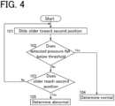
arithmetic part 44 will be described with reference to a flowchart ofFig. 4 . - When the determination operation is started, the
arithmetic part 44 slides theslider 8 of thesample injection mechanism 6 from the first position toward the second position (Step 101). Thearithmetic part 44 constantly compares, with the threshold, a detected pressure of thepressure sensor 30 read by thecontrol device 42 while theslider 8 is slid from the first position to the second position, and determines whether the detected pressure falls below the threshold (Step 102). If the detected pressure falls below the threshold before theslider 8 reaches the second position, it is determined to be normal (Steps 103 and 104), and if the detected pressure does not fall below the threshold before theslider 8 reaches the second position, it is determined to be abnormal (Steps 103 and 105). - Note that the above embodiment merely shows an example of an embodiment of the instrument for elemental analysis according to the present invention. The embodiment of the instrument for elemental analysis according to the present invention is as described below.
- The embodiment of the instrument for elemental analysis according to the present invention includes a combustion tube that has a sample injection port with an open top and is for combusting a liquid sample in the inside, a sample injection mechanism having a nozzle and a slider, the nozzle being for injecting a sample into the combustion tube, and the slider being configured to slide between a first position and a second position above the combustion tube, sample injection mechanism being configured so that the sample injection port of the combustion tube is sealed in a state where the slider is positioned at the first position, and the sample injection port is unsealed and the nozzle is positioned above the sample injection port in a state where the slider is at the second position, a carrier gas supply flow path communicating with the inside of the combustion tube to supply carrier gas into the combustion tube, a pressure sensor that detects pressure in the carrier gas supply flow path, a detector for detecting components in sample gas flowing out of the combustion tube, and an arithmetic part configured to determine an abnormality degree of a state in a system between the combustion tube and the detector based on a change in pressure, which is detected by the pressure sensor, at the time when the slider of the sample injection mechanism slides from the first position to the second position.
- A first aspect of the embodiment of the instrument for elemental analysis according to the present invention further includes a threshold setting part configured to set a threshold for the determination based on pressure immediately before the slider starts sliding from the first position to the second position. The arithmetic part is configured to determine normal when pressure detected by the pressure sensor falls below the threshold set by the threshold setting part during a period in which the slider slides from the first position to the second position. According to such an aspect, it is possible to easily determine the presence or absence of a pressure fluctuation in the combustion tube.
- In a second aspect of the embodiment of the instrument for elemental analysis according to the present invention, the arithmetic part is configured to execute the determination by sliding the slider from the first position to the second position after the instrument for elemental analysis is started and before sample injection into the combustion tube is executed. According to such an aspect, when the instrument for elemental analysis is started, determination as to whether or not there is an abnormality in the combustion tube or the like is performed automatically. Accordingly, it is possible to prevent analysis from being started in a state where there is an abnormality in the combustion tube or the like. This second aspect can be combined with the first aspect.
- In a third aspect of the embodiment of the instrument for elemental analysis according to the present invention, the arithmetic part is configured to execute the determination by sliding the slider from the first position to the second position at the time when an instruction to execute the determination is input by the user. According to such an aspect, determination as to whether or not there is an abnormality in the combustion tube or the like can be performed at a timing desired by the user.
- 2:
- Combustion tube
- 3:
- Sample injection port
- 4:
- Electric furnace
- 6:
- Sample injection mechanism
- 8:
- Slider
- 10:
- Nozzle
- 12:
- Sample injection flow path
- 14:
- Switching valve
- 16:
- Syringe pump
- 18:
- Sample gas flow path
- 20:
- Dehumidifier
- 22:
- Detector
- 24:
- High-purity air source
- 26:
- Carrier gas supply flow path
- 28, 36:
- Resistance pipe
- 30, 38:
- Pressure sensor
- 32, 40:
- Flow rate control valve
- 34:
- Sparging gas supply flow path
- 42:
- Control device
- 44:
- Arithmetic part
- 46:
- Threshold setting part
Claims (4)
- An instrument for elemental analysis comprising:a combustion tube (2) that has a sample injection port (3) with an open top and is for combusting a liquid sample therein;a sample injection mechanism (6) having a nozzle (10) and a slider (8),the nozzle being for injecting a sample into the combustion tube, the slider being configured to slide between a first position and a second position above the combustion tube, the sample injection mechanism being configured so that the sample injection port of the combustion tube is sealed in a state where the slider is positioned at the first position, and the sample injection port is unsealed and the nozzle is positioned above the sample injection port in a state where the slider is positioned at the second position;a carrier gas supply flow path (26) communicating with inside of the combustion tube to supply carrier gas into the combustion tube;a pressure sensor (30) that detects pressure in the carrier gas supply flow path;a detector (22) for detecting components in sample gas flowing out of the combustion tube; andan arithmetic part (44) configured to determine an abnormality degree of a state in a system between the combustion tube and the detector based on a change in pressure, which is detected by the pressure sensor, at the time when the slider of the sample injection mechanism slides from the first position to the second position.
- The instrument for elemental analysis according to claim 1, further comprising a threshold setting part (46) configured to set a threshold for the determination based on pressure immediately before the slider starts sliding from the first position to the second position, wherein
the arithmetic part is configured to determine normal when pressure detected by the pressure sensor falls below the threshold set by the threshold setting part during a period in which the slider slides from the first position to the second position. - The instrument for elemental analysis according to claim 1, wherein
the arithmetic part is configured to execute the determination by sliding the slider from the first position to the second position after the instrument for elemental analysis is started and before sample injection into the combustion tube is executed. - The instrument for elemental analysis according to claim 1, wherein
the arithmetic part is configured to execute the determination by sliding the slider from the first position to the second position at the time when an instruction to execute the determination is input by a user.
Applications Claiming Priority (2)
| Application Number | Priority Date | Filing Date | Title |
|---|---|---|---|
| JP2019156869 | 2019-08-29 | ||
| PCT/JP2020/029783WO2021039305A1 (en) | 2019-08-29 | 2020-08-04 | Instrument for elemental analysis |
Publications (3)
| Publication Number | Publication Date |
|---|---|
| EP4024046A1 EP4024046A1 (en) | 2022-07-06 |
| EP4024046A4 EP4024046A4 (en) | 2023-09-27 |
| EP4024046B1true EP4024046B1 (en) | 2024-10-02 |
Family
ID=74683823
Family Applications (1)
| Application Number | Title | Priority Date | Filing Date |
|---|---|---|---|
| EP20857546.4AActiveEP4024046B1 (en) | 2019-08-29 | 2020-08-04 | Instrument for elemental analysis |
Country Status (5)
| Country | Link |
|---|---|
| US (1) | US11808744B2 (en) |
| EP (1) | EP4024046B1 (en) |
| JP (1) | JP7103527B2 (en) |
| CN (1) | CN113950624A (en) |
| WO (1) | WO2021039305A1 (en) |
Families Citing this family (1)
| Publication number | Priority date | Publication date | Assignee | Title |
|---|---|---|---|---|
| WO2006053093A2 (en) | 2004-11-08 | 2006-05-18 | Cluster Resources, Inc. | System and method of providing system jobs within a compute environment |
Family Cites Families (20)
| Publication number | Priority date | Publication date | Assignee | Title |
|---|---|---|---|---|
| US3530292A (en)* | 1967-04-26 | 1970-09-22 | Union Carbide Corp | Apparatus and method for determination and measurement of carbon in aqueous solutions |
| US3840341A (en)* | 1972-03-03 | 1974-10-08 | Ionics | Organic carbon method and analyzer |
| JPS5315397B2 (en)* | 1972-05-02 | 1978-05-24 | ||
| JPS59122948A (en) | 1982-12-29 | 1984-07-16 | Shimadzu Corp | Combustion type water quality analyzer |
| US4968485A (en)* | 1987-09-25 | 1990-11-06 | Shimadzu Corporation | Arrangements for preparative route leading to water analysis |
| JP3351327B2 (en)* | 1997-11-28 | 2002-11-25 | 株式会社島津製作所 | Sample analyzer |
| JP2000221183A (en)* | 1999-01-29 | 2000-08-11 | Horiba Ltd | Flow abnormality determining method of water quality analyzer |
| DE10003613A1 (en)* | 2000-01-28 | 2001-08-02 | Volkswagen Ag | Detecting leaks in motor vehicle internal combustion engine combustion chamber involves comparing internal pressure in combustion chamber before ignition with threshold value |
| JP4126858B2 (en) | 2000-07-18 | 2008-07-30 | 株式会社島津製作所 | Elemental analyzer |
| US6830730B2 (en)* | 2001-09-11 | 2004-12-14 | Spectrolanalytical Instruments | Method and apparatus for the on-stream analysis of total sulfur and/or nitrogen in petroleum products |
| JP2005221397A (en)* | 2004-02-06 | 2005-08-18 | Hitachi Naka Instruments Co Ltd | Atomic absorption spectrophotometer |
| JP5585434B2 (en)* | 2010-12-21 | 2014-09-10 | 株式会社島津製作所 | Total organic carbon measuring device |
| EP2662690B1 (en)* | 2011-01-06 | 2016-09-14 | Shimadzu Corporation | Measurement device for total organic carbon and its use |
| US9435758B2 (en)* | 2011-07-19 | 2016-09-06 | Leco Corporation | Bidirectional ballast |
| JP2013185884A (en)* | 2012-03-07 | 2013-09-19 | Shimadzu Corp | Water quality analyzer |
| CN202837308U (en)* | 2012-08-10 | 2013-03-27 | 宇星科技发展(深圳)有限公司 | Dry-type oxidation reactor |
| JP2018066627A (en)* | 2016-10-19 | 2018-04-26 | 株式会社Ube科学分析センター | Pretreatment equipment for elementary analysis and elementary analysis system, and pretreatment method for elementary analysis and elementary analysis method |
| WO2018089482A1 (en)* | 2016-11-08 | 2018-05-17 | O.I. Corporation | Smart slide |
| CN206891667U (en)* | 2017-06-21 | 2018-01-16 | 长沙开元仪器股份有限公司 | A kind of coal sample detector and its fire door automatic sealing device |
| CN208187667U (en)* | 2018-05-31 | 2018-12-04 | 北京诺德泰科仪器仪表有限公司 | The device of the pressure application leak detection and Data correction of elemental analyser gas piping |
- 2020
- 2020-08-04EPEP20857546.4Apatent/EP4024046B1/enactiveActive
- 2020-08-04WOPCT/JP2020/029783patent/WO2021039305A1/ennot_activeCeased
- 2020-08-04USUS17/608,690patent/US11808744B2/enactiveActive
- 2020-08-04CNCN202080042690.0Apatent/CN113950624A/enactivePending
- 2020-08-04JPJP2021542680Apatent/JP7103527B2/enactiveActive
Also Published As
| Publication number | Publication date |
|---|---|
| US11808744B2 (en) | 2023-11-07 |
| US20220214320A1 (en) | 2022-07-07 |
| EP4024046A4 (en) | 2023-09-27 |
| CN113950624A (en) | 2022-01-18 |
| EP4024046A1 (en) | 2022-07-06 |
| JPWO2021039305A1 (en) | 2021-12-16 |
| JP7103527B2 (en) | 2022-07-20 |
| WO2021039305A1 (en) | 2021-03-04 |
Similar Documents
| Publication | Publication Date | Title |
|---|---|---|
| KR101723883B1 (en) | Apparatus and method for measuring total organic carbon with integrated oxidation reactor | |
| CN103415768B (en) | Measurement device for total organic carbon | |
| US20180306682A1 (en) | Smart pump for a portable gas detection instrument | |
| JP6220043B2 (en) | Flow sensor circuit for monitoring fluid flow paths | |
| EP4024046B1 (en) | Instrument for elemental analysis | |
| KR101359903B1 (en) | Total organic carbon and total nitrogen measurement device for minimizing deviation of the measured value by air flow variation | |
| KR100570552B1 (en) | Moisture analyzer | |
| EP3901629B1 (en) | Water quality analyzer | |
| JP5962577B2 (en) | Gas chromatograph | |
| JP6302593B1 (en) | Exhaust gas analyzer | |
| JP2009031113A (en) | Liquid chromatograph mass spectrometer | |
| CN211040499U (en) | Gas analysis device and gas leak detection device | |
| CN109425514B (en) | Fluid sampling device | |
| KR20180128848A (en) | Probe device, analysis apparatus for exhaust gas and correction method | |
| US11703488B2 (en) | Combustion analyzing apparatus using carrier gas flow adjuster to increase a carrier gas flow rate during measurement | |
| TWI657887B (en) | ALL-IN-ONE VOCs MEASUREMENT INSTRUMENT | |
| KR102752317B1 (en) | Gas analyzer | |
| JP6380216B2 (en) | Gas chromatograph | |
| US12222336B2 (en) | Sample introduction device | |
| JP2010055500A (en) | Flow controller and flow control method | |
| CN113544504A (en) | Liquid chromatograph analysis system | |
| US20090196795A1 (en) | Microchip inspection device | |
| JPH01105150A (en) | Abnormality detection method in clogging point meter | |
| JPS62108135A (en) | Chemical emission type analyzer | |
| JPH10300734A (en) | Gas chromatograph |
Legal Events
| Date | Code | Title | Description |
|---|---|---|---|
| STAA | Information on the status of an ep patent application or granted ep patent | Free format text:STATUS: THE INTERNATIONAL PUBLICATION HAS BEEN MADE | |
| PUAI | Public reference made under article 153(3) epc to a published international application that has entered the european phase | Free format text:ORIGINAL CODE: 0009012 | |
| STAA | Information on the status of an ep patent application or granted ep patent | Free format text:STATUS: REQUEST FOR EXAMINATION WAS MADE | |
| 17P | Request for examination filed | Effective date:20220104 | |
| AK | Designated contracting states | Kind code of ref document:A1 Designated state(s):AL AT BE BG CH CY CZ DE DK EE ES FI FR GB GR HR HU IE IS IT LI LT LU LV MC MK MT NL NO PL PT RO RS SE SI SK SM TR | |
| DAV | Request for validation of the european patent (deleted) | ||
| DAX | Request for extension of the european patent (deleted) | ||
| A4 | Supplementary search report drawn up and despatched | Effective date:20230824 | |
| RIC1 | Information provided on ipc code assigned before grant | Ipc:G01N 33/18 20060101ALN20230818BHEP Ipc:G01N 31/12 20060101AFI20230818BHEP | |
| GRAP | Despatch of communication of intention to grant a patent | Free format text:ORIGINAL CODE: EPIDOSNIGR1 | |
| STAA | Information on the status of an ep patent application or granted ep patent | Free format text:STATUS: GRANT OF PATENT IS INTENDED | |
| RIC1 | Information provided on ipc code assigned before grant | Ipc:G01N 33/18 20060101ALN20240531BHEP Ipc:G01N 31/12 20060101AFI20240531BHEP | |
| INTG | Intention to grant announced | Effective date:20240618 | |
| GRAS | Grant fee paid | Free format text:ORIGINAL CODE: EPIDOSNIGR3 | |
| GRAA | (expected) grant | Free format text:ORIGINAL CODE: 0009210 | |
| STAA | Information on the status of an ep patent application or granted ep patent | Free format text:STATUS: THE PATENT HAS BEEN GRANTED | |
| AK | Designated contracting states | Kind code of ref document:B1 Designated state(s):AL AT BE BG CH CY CZ DE DK EE ES FI FR GB GR HR HU IE IS IT LI LT LU LV MC MK MT NL NO PL PT RO RS SE SI SK SM TR | |
| REG | Reference to a national code | Ref country code:GB Ref legal event code:FG4D | |
| REG | Reference to a national code | Ref country code:CH Ref legal event code:EP | |
| REG | Reference to a national code | Ref country code:DE Ref legal event code:R096 Ref document number:602020038828 Country of ref document:DE | |
| REG | Reference to a national code | Ref country code:IE Ref legal event code:FG4D | |
| REG | Reference to a national code | Ref country code:LT Ref legal event code:MG9D | |
| REG | Reference to a national code | Ref country code:NL Ref legal event code:MP Effective date:20241002 | |
| REG | Reference to a national code | Ref country code:AT Ref legal event code:MK05 Ref document number:1728839 Country of ref document:AT Kind code of ref document:T Effective date:20241002 | |
| PG25 | Lapsed in a contracting state [announced via postgrant information from national office to epo] | Ref country code:NL Free format text:LAPSE BECAUSE OF FAILURE TO SUBMIT A TRANSLATION OF THE DESCRIPTION OR TO PAY THE FEE WITHIN THE PRESCRIBED TIME-LIMIT Effective date:20241002 | |
| PG25 | Lapsed in a contracting state [announced via postgrant information from national office to epo] | Ref country code:NL Free format text:LAPSE BECAUSE OF FAILURE TO SUBMIT A TRANSLATION OF THE DESCRIPTION OR TO PAY THE FEE WITHIN THE PRESCRIBED TIME-LIMIT Effective date:20241002 | |
| PG25 | Lapsed in a contracting state [announced via postgrant information from national office to epo] | Ref country code:IS Free format text:LAPSE BECAUSE OF FAILURE TO SUBMIT A TRANSLATION OF THE DESCRIPTION OR TO PAY THE FEE WITHIN THE PRESCRIBED TIME-LIMIT Effective date:20250202 Ref country code:HR Free format text:LAPSE BECAUSE OF FAILURE TO SUBMIT A TRANSLATION OF THE DESCRIPTION OR TO PAY THE FEE WITHIN THE PRESCRIBED TIME-LIMIT Effective date:20241002 Ref country code:PT Free format text:LAPSE BECAUSE OF FAILURE TO SUBMIT A TRANSLATION OF THE DESCRIPTION OR TO PAY THE FEE WITHIN THE PRESCRIBED TIME-LIMIT Effective date:20250203 | |
| PG25 | Lapsed in a contracting state [announced via postgrant information from national office to epo] | Ref country code:FI Free format text:LAPSE BECAUSE OF FAILURE TO SUBMIT A TRANSLATION OF THE DESCRIPTION OR TO PAY THE FEE WITHIN THE PRESCRIBED TIME-LIMIT Effective date:20241002 | |
| PG25 | Lapsed in a contracting state [announced via postgrant information from national office to epo] | Ref country code:BG Free format text:LAPSE BECAUSE OF FAILURE TO SUBMIT A TRANSLATION OF THE DESCRIPTION OR TO PAY THE FEE WITHIN THE PRESCRIBED TIME-LIMIT Effective date:20241002 | |
| PG25 | Lapsed in a contracting state [announced via postgrant information from national office to epo] | Ref country code:ES Free format text:LAPSE BECAUSE OF FAILURE TO SUBMIT A TRANSLATION OF THE DESCRIPTION OR TO PAY THE FEE WITHIN THE PRESCRIBED TIME-LIMIT Effective date:20241002 | |
| PG25 | Lapsed in a contracting state [announced via postgrant information from national office to epo] | Ref country code:NO Free format text:LAPSE BECAUSE OF FAILURE TO SUBMIT A TRANSLATION OF THE DESCRIPTION OR TO PAY THE FEE WITHIN THE PRESCRIBED TIME-LIMIT Effective date:20250102 | |
| PG25 | Lapsed in a contracting state [announced via postgrant information from national office to epo] | Ref country code:LV Free format text:LAPSE BECAUSE OF FAILURE TO SUBMIT A TRANSLATION OF THE DESCRIPTION OR TO PAY THE FEE WITHIN THE PRESCRIBED TIME-LIMIT Effective date:20241002 Ref country code:AT Free format text:LAPSE BECAUSE OF FAILURE TO SUBMIT A TRANSLATION OF THE DESCRIPTION OR TO PAY THE FEE WITHIN THE PRESCRIBED TIME-LIMIT Effective date:20241002 Ref country code:GR Free format text:LAPSE BECAUSE OF FAILURE TO SUBMIT A TRANSLATION OF THE DESCRIPTION OR TO PAY THE FEE WITHIN THE PRESCRIBED TIME-LIMIT Effective date:20250103 | |
| PG25 | Lapsed in a contracting state [announced via postgrant information from national office to epo] | Ref country code:PL Free format text:LAPSE BECAUSE OF FAILURE TO SUBMIT A TRANSLATION OF THE DESCRIPTION OR TO PAY THE FEE WITHIN THE PRESCRIBED TIME-LIMIT Effective date:20241002 Ref country code:CZ Free format text:LAPSE BECAUSE OF FAILURE TO SUBMIT A TRANSLATION OF THE DESCRIPTION OR TO PAY THE FEE WITHIN THE PRESCRIBED TIME-LIMIT Effective date:20241002 | |
| PG25 | Lapsed in a contracting state [announced via postgrant information from national office to epo] | Ref country code:RS Free format text:LAPSE BECAUSE OF FAILURE TO SUBMIT A TRANSLATION OF THE DESCRIPTION OR TO PAY THE FEE WITHIN THE PRESCRIBED TIME-LIMIT Effective date:20250102 | |
| PG25 | Lapsed in a contracting state [announced via postgrant information from national office to epo] | Ref country code:SM Free format text:LAPSE BECAUSE OF FAILURE TO SUBMIT A TRANSLATION OF THE DESCRIPTION OR TO PAY THE FEE WITHIN THE PRESCRIBED TIME-LIMIT Effective date:20241002 | |
| REG | Reference to a national code | Ref country code:DE Ref legal event code:R097 Ref document number:602020038828 Country of ref document:DE | |
| PG25 | Lapsed in a contracting state [announced via postgrant information from national office to epo] | Ref country code:DK Free format text:LAPSE BECAUSE OF FAILURE TO SUBMIT A TRANSLATION OF THE DESCRIPTION OR TO PAY THE FEE WITHIN THE PRESCRIBED TIME-LIMIT Effective date:20241002 | |
| PG25 | Lapsed in a contracting state [announced via postgrant information from national office to epo] | Ref country code:EE Free format text:LAPSE BECAUSE OF FAILURE TO SUBMIT A TRANSLATION OF THE DESCRIPTION OR TO PAY THE FEE WITHIN THE PRESCRIBED TIME-LIMIT Effective date:20241002 | |
| PG25 | Lapsed in a contracting state [announced via postgrant information from national office to epo] | Ref country code:RO Free format text:LAPSE BECAUSE OF FAILURE TO SUBMIT A TRANSLATION OF THE DESCRIPTION OR TO PAY THE FEE WITHIN THE PRESCRIBED TIME-LIMIT Effective date:20241002 | |
| PG25 | Lapsed in a contracting state [announced via postgrant information from national office to epo] | Ref country code:SK Free format text:LAPSE BECAUSE OF FAILURE TO SUBMIT A TRANSLATION OF THE DESCRIPTION OR TO PAY THE FEE WITHIN THE PRESCRIBED TIME-LIMIT Effective date:20241002 | |
| PLBE | No opposition filed within time limit | Free format text:ORIGINAL CODE: 0009261 | |
| STAA | Information on the status of an ep patent application or granted ep patent | Free format text:STATUS: NO OPPOSITION FILED WITHIN TIME LIMIT | |
| PG25 | Lapsed in a contracting state [announced via postgrant information from national office to epo] | Ref country code:SE Free format text:LAPSE BECAUSE OF FAILURE TO SUBMIT A TRANSLATION OF THE DESCRIPTION OR TO PAY THE FEE WITHIN THE PRESCRIBED TIME-LIMIT Effective date:20241002 | |
| 26N | No opposition filed | Effective date:20250703 |