EP4018039B1 - Rail fastening device - Google Patents
Rail fastening deviceDownload PDFInfo
- Publication number
- EP4018039B1 EP4018039B1EP20747083.2AEP20747083AEP4018039B1EP 4018039 B1EP4018039 B1EP 4018039B1EP 20747083 AEP20747083 AEP 20747083AEP 4018039 B1EP4018039 B1EP 4018039B1
- Authority
- EP
- European Patent Office
- Prior art keywords
- clip
- washer
- aperture
- elongate
- fastening device
- Prior art date
- Legal status (The legal status is an assumption and is not a legal conclusion. Google has not performed a legal analysis and makes no representation as to the accuracy of the status listed.)
- Active
Links
Images


Classifications
- B—PERFORMING OPERATIONS; TRANSPORTING
- B66—HOISTING; LIFTING; HAULING
- B66C—CRANES; LOAD-ENGAGING ELEMENTS OR DEVICES FOR CRANES, CAPSTANS, WINCHES, OR TACKLES
- B66C7/00—Runways, tracks or trackways for trolleys or cranes
- B66C7/08—Constructional features of runway rails or rail mountings
- E—FIXED CONSTRUCTIONS
- E01—CONSTRUCTION OF ROADS, RAILWAYS, OR BRIDGES
- E01B—PERMANENT WAY; PERMANENT-WAY TOOLS; MACHINES FOR MAKING RAILWAYS OF ALL KINDS
- E01B9/00—Fastening rails on sleepers, or the like
- E01B9/02—Fastening rails, tie-plates, or chairs directly on sleepers or foundations; Means therefor
- E01B9/32—Fastening on steel sleepers with clamp members
- E01B9/34—Fastening on steel sleepers with clamp members by resilient steel clips
- E—FIXED CONSTRUCTIONS
- E01—CONSTRUCTION OF ROADS, RAILWAYS, OR BRIDGES
- E01B—PERMANENT WAY; PERMANENT-WAY TOOLS; MACHINES FOR MAKING RAILWAYS OF ALL KINDS
- E01B9/00—Fastening rails on sleepers, or the like
- E01B9/66—Rail fastenings allowing the adjustment of the position of the rails, so far as not included in the preceding groups
Definitions
- This inventionrelates to a rail fastening device and to a method of fastening a rail in position using said rail fastening device.
- Cranes for dockyards and container terminals etc.run on steel rails which are fastened to the ground or other support structure by a plurality of rail fastening devices arranged at intervals along the rail.
- the base of a typical railcomprises a pair of oppositely-directed longitudinal flanges, against which the fastening devices clamp to hold the rail in-situ.
- WO2015/165790discloses a typical rail fastening device comprising a clip and an overlying washer for displaceably fastening to a rail support by a bolt which upstands from the support.
- the clipcomprises a rear body portion and forwardly projecting cap portion adapted for abutment with a lateral flange on the foot of the rail.
- the boltextends through an aperture in the body portion of the clip, the aperture being elongate with its longer axis extending in a direction oblique to the side of the rail, to enable the clip to be slid towards the rail.
- the upper surface of the body portion of the clip surrounding the apertureis inclined upwardly from its rear end towards the cap portion of the clip.
- An apertured washeris provided for fitting onto the bolt over the clip, the washer comprising a bottom surface which inclined at a complementary angle to the upper surface of the clip, such that the upper surface of the washer lies in a plane which extends normal to the axis of the bolt.
- the clipIn use, the clip is fitted onto a bolt positioned adjacent the rail whereupon the washer is fitted on top of the clip before a nut is loosely secured to the upper end of the bolt.
- the clipis then slid forwardly towards the rail, which causes the washer to slide down the inclined upper surface of the clip as the rear end of the clip aperture is pushed closer to the bolt.
- the nutcan be tightened to fasten the clip in-situ.
- the nutis rotated by hand until it abuts the top surface of the washer and is finger tight, whereupon the nut is fully tightened using a spanner.
- Cranes for dockyards and container terminals etc.are heavy and can carry substantial loads.
- the clipis subjected to substantial lateral forces by the rail.
- a problem with typical rail fastening devices of the above-mentioned typeis that the forces acting on the clip are applied to the bolt via the washer which, on some occasions, can cause the washer to fail as it is not designed to withstand such forces. In other instances, this can cause the bolt to bend or break since the washer applies a lateral load to the bolt at a point which is located some distance away from the point where the bolt is anchored to the ground.
- the front side wall of the elongate clip aperturemay be profiled to provide a projection which extends into the aperture at a point below the upper end of the aperture. This helps to ensure that the point of contact between the fastening member and the clip is as low as possible. Ideally, the projection extends into the aperture at a point that is more adjacent the lower end of the aperture than the upper end.
- the planar upper surface of the body portion of the clip surrounding the aperturemay be inclined upwardly from the rear towards the front the clip.
- the washermay comprise a bottom surface which is inclined at a complementary angle to the upper surface of the clip, such that in use the upper surface of the washer lies in a plane which extends normal to the axis of the fastener.
- the washermay comprise an outwardly-facing straight side edge surface, the pivot formation being provided by one end of the surface.
- the rear upstanding formation on the surface of the clipmay comprise a straight side edge surface which faces towards and extends parallel to the elongate clip aperture.
- the washermay comprise a projection which extends outwardly of its outwardly-facing straight side edge surface over the rear upstanding formation on the surface of the clip: this arrangement helps to ensure that the washer is mounted in the correct orientation on the clip.
- the washermay be caused to pivot to move the fastening member relative to the clip in a direction which brings the fastening member into contact with the front side wall of the elongate clip aperture.
- the fastening devicecomprises an externally threaded shaft, such as a shaft of a bolt, extending upwardly from a support surface, the method comprising rotating a nut that is threadably mounted on the shaft.
- the fastening devicecomprises a bolt having an externally threaded shaft which extends into an internally threaded member fixed to a support surface, the method comprising rotating a head of the bolt.
- the clipmay be urged forwardly following rotation of the washer, for example by striking the rear thereof with a hammer or other object, before the fastening member is fully tightened. This latter tightening will not cause rotation of the washer or rearward displacement of the clip and the washer.
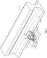
- a rail fastening device 10for fastening an elongate rail 11 to a rail support 12.
- the rail fastening device 10is secured in position by a ground anchor bolt 14, which extends upwardly from the rail support 12 through the rail fastening device 10.
- the rail fastening device 10is slid towards the rail 11 to engage a laterally projecting flange 13 at the base of the rail 11.
- the rail fastening device 10is then locked in situ by tightening a nut 15 threadably mounted to the upper end of the bolt 14.
- the rail fastening device 10could be secured by tightening the head of a bolt which extends downwardly through the device 10 into the rail support 12.
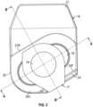
- the rail fastening device 10comprises a clip 16 and a washer 17 which are displaceably fastened to the rail support 12 by the upstanding bolt 14.
- the clip 16is formed of a cast metal and has a front, a rear and opposite sides.
- the front of the clip 16comprises a raised forwardly-extending projecting cap portion 21 adapted to abut the flange 13 of the rail 11.
- An elastomeric cap 22is a provided on the underside of the projecting cap 21 for engaging the rail 11.
- the rear of the clip 16comprises a body 20 having an elongate aperture 18 extending obliquely forwardly between opposite sides of the clip 16 towards the front thereof.
- the elongate aperture 18has a front side wall 18F, a parallel rear side wall 18R and arcuate end walls.
- the washer 17is slidable along a substantially planar upper surface 20U of the body 20 of the clip surrounding the elongate clip aperture 18, so that the clip 16 can be slid towards the rail 11 with the bolt 14 in-situ: it will be appreciated that as the clip 16 is moved in direction A towards the rail 11, the left-hand end of the clip aperture 18 moves towards the bolt 14, as viewed in Figure 3 .
- the rear edge of the body 20 of the clip 16comprises an elongate upstanding wall formation 24, which comprises a straight front side edge surface 24F which faces towards and extends parallel to the elongate clip aperture 18.
- the cap portion 21 and the upstanding wall formation 24 of the clip 16are disposed on respective opposite sides of the clip aperture 18.
- the upper surface 20U of the body 20 of the clip 16is substantially flat and extends upwardly and forwardly at a shallow angle from the left-hand end of the clip aperture 18 towards its right-hand end, as viewed in Figures 3 and 4 .
- the underside of the washer 17comprises a complementary flat surface, which is similarly angled, so that the upper surface of the washer 17 remains at a constant atitude as the washer 17 is slid axially of the elongate clip aperture 18.
- the one side of the washer 17comprises an outwardly-facing straight side edge surface 17S which extends tangentially relative to the washer aperture 19.
- a projection 17Pextends outwardly of from the upper edge of the outwardly-facing straight side edge surface 17S of the washer 17 and over the elongate upstanding wall formation 24 on the rear end the clip 16: this arrangement helps to ensure that the washer 17 is mounted in the correct orientation on the upper surface 20U of the clip 16.
- the other diametrically opposite side of the washer 17comprises a radially projecting abutment formation 17A.
- the forwardly-projecting cap portion 21 of the clip 20comprises a rear upstanding wall formation 21R which extends parallel to the elongate clip aperture 18.
- the front surface 24F of the elongate upstanding wall formation 24 and the upstanding wall formation 21R of the cap portion 21define a channel having a bottom wall formed by the substantially planar upper surface 20U of the body 20 of the clip 16 surrounding the elongate clip aperture 18.
- the front side wall 18F of the elongate clip aperture 18is chamfered at it opposite ends to provide a projection 18X which extends into the aperture 18 at a point that is more adjacent the lower end of the aperture 18 than the upper end.
- the clip 16in order to fasten the rail 11 in-situ, the clip 16 is initially engaged over the upstanding bolt 14, whereupon the washer 17 is placed around the bolt 14 to engage the upper surface of the clip 16 prior to fitting the nut 15.
- the clip 16is then slid forwardly in direction A towards the rail 11, which causes the clip 16 to move laterally to the right in direction B, such that the washer 17 and bolt 14 come in closer proximity to the left-hand end of the clip aperture 18.
- the nut 15is then tightened by hand until it engages the upper surface of the washer 17. It will be appreciated that the upper surface of the washer 17 extends in a plane that substantially normal to the longitudinal axis of the bolt 14.
- the upper surface of the washer 17moves downwardly as the clip 16 is slid in direction A towards the rail, owing to the cooperation of the angled flat upper surface 20U of the body 20 of the clip 16 with the complementary angled bottom surface of the washer 17.
- This arrangementprovides a self-locking feature to resist movement of the clip 16 away from the rail 11 once the nut 15 is fully tightened.
- the nut 15is hand-tightened to engage the washer 17, whereupon the nut 15 can be further tightened using a spanner.
- Thiscauses the nut 15 to frictionally engage the upper surface of the washer 17, thereby causing the washer 17 to rotate in the clockwise tightening direction about the longitudinal axis of the bolt 14 until the right-hand end of the outwardly-facing straight side edge surface 17S thereof abuts the front side edge surface 24F of the upstanding wall formation 24 on the rear of the clip 16 at point A.
- the clip 16can be urged forwardly following rotation of the washer 17, by striking the rear end thereof with a hammer or other object, before the nut 15 is fully tightened.
- a rail fastening device in accordance with the present inventionis simple and inexpensive in construction and comprises a clip 16 and a washer 17 for fastening to a rail support 12 by an upstanding bolt 14 having a nut 15, which can be tightened to lock the device 10 in position.
- the clip 16 and washer 17comprise respective apertures 18, 19 for receiving the bolt 14.
- the washer 17is adapted to rotate as the nut 15 is tightened until a formation on the washer 17 abuts an upstanding formation 24 on the rear of the clip 16 at point A, whereupon continued tightening of the nut 15 causes the washer 17 to pivot at point A around an offset axis, so as to bring the bolt 14 into contact with a front surface 18F of the clip aperture 18. Further tightening of the nut 15 pivots the washer 17 to a point where any displacement force applied to the clip 16 by the rail is applied directly to the bolt 14 and not to the washer 17. In this manner, the risk of the washer failing, or bolt 14 bending is avoided.
Landscapes
- Engineering & Computer Science (AREA)
- Mechanical Engineering (AREA)
- Architecture (AREA)
- Civil Engineering (AREA)
- Structural Engineering (AREA)
- Clamps And Clips (AREA)
- Bolts, Nuts, And Washers (AREA)
- Machines For Laying And Maintaining Railways (AREA)
Description
- This invention relates to a rail fastening device and to a method of fastening a rail in position using said rail fastening device.
- Cranes for dockyards and container terminals etc. run on steel rails which are fastened to the ground or other support structure by a plurality of rail fastening devices arranged at intervals along the rail. The base of a typical rail comprises a pair of oppositely-directed longitudinal flanges, against which the fastening devices clamp to hold the rail in-situ.
WO2015/165790 discloses a typical rail fastening device comprising a clip and an overlying washer for displaceably fastening to a rail support by a bolt which upstands from the support. The clip comprises a rear body portion and forwardly projecting cap portion adapted for abutment with a lateral flange on the foot of the rail. The bolt extends through an aperture in the body portion of the clip, the aperture being elongate with its longer axis extending in a direction oblique to the side of the rail, to enable the clip to be slid towards the rail. The upper surface of the body portion of the clip surrounding the aperture is inclined upwardly from its rear end towards the cap portion of the clip. An apertured washer is provided for fitting onto the bolt over the clip, the washer comprising a bottom surface which inclined at a complementary angle to the upper surface of the clip, such that the upper surface of the washer lies in a plane which extends normal to the axis of the bolt.- In use, the clip is fitted onto a bolt positioned adjacent the rail whereupon the washer is fitted on top of the clip before a nut is loosely secured to the upper end of the bolt. The clip is then slid forwardly towards the rail, which causes the washer to slide down the inclined upper surface of the clip as the rear end of the clip aperture is pushed closer to the bolt. Once in position, the nut can be tightened to fasten the clip in-situ. Typically, the nut is rotated by hand until it abuts the top surface of the washer and is finger tight, whereupon the nut is fully tightened using a spanner.
- Cranes for dockyards and container terminals etc. are heavy and can carry substantial loads. Hence, it will be appreciated that the clip is subjected to substantial lateral forces by the rail. A problem with typical rail fastening devices of the above-mentioned type is that the forces acting on the clip are applied to the bolt via the washer which, on some occasions, can cause the washer to fail as it is not designed to withstand such forces. In other instances, this can cause the bolt to bend or break since the washer applies a lateral load to the bolt at a point which is located some distance away from the point where the bolt is anchored to the ground.
- With the foregoing in mind, we have now devised an improved rail fastening device. In accordance with the present invention, there is provided a rail fastening device having the features of claim 1.
- Further preferred embodiments are defined by the features of dependent claims 2-8.
- In use, when the rail fastening device is fitted in-situ by tightening the fastener, friction between the fastener and the washer causes the washer to rotate forwardly to a point where the front side wall of the elongate clip aperture extends as a chord across the washer aperture. In this manner, when a load on the rail acts to displace the clip rearwardly, the force is immediately transferred to the fastener because the washer has rotated into a position where it is away from the load bearing side of the fastener. In this manner, the risk of the washer breaking under applied loads is avoided. Also, since the underlying clip and not the washer contact the load bearing side of the fastener, the force applied to the fastener is applied closer to where the fastener is anchored and thus the risk of bending the fastener is avoided.
- The front side wall of the elongate clip aperture may be profiled to provide a projection which extends into the aperture at a point below the upper end of the aperture. This helps to ensure that the point of contact between the fastening member and the clip is as low as possible. Ideally, the projection extends into the aperture at a point that is more adjacent the lower end of the aperture than the upper end.
- The planar upper surface of the body portion of the clip surrounding the aperture may be inclined upwardly from the rear towards the front the clip. The washer may comprise a bottom surface which is inclined at a complementary angle to the upper surface of the clip, such that in use the upper surface of the washer lies in a plane which extends normal to the axis of the fastener.
- The washer may comprise an outwardly-facing straight side edge surface, the pivot formation being provided by one end of the surface.
- The rear upstanding formation on the surface of the clip may comprise a straight side edge surface which faces towards and extends parallel to the elongate clip aperture. The washer may comprise a projection which extends outwardly of its outwardly-facing straight side edge surface over the rear upstanding formation on the surface of the clip: this arrangement helps to ensure that the washer is mounted in the correct orientation on the clip.
- Also in accordance with the present invention, there is provided a method of fastening a rail in position using a fastening device as hereinbefore defined, the method having the features of claim 9.
- Further preferred embodiments are defined by the features of dependent claims 10-15.
- The washer may be caused to pivot to move the fastening member relative to the clip in a direction which brings the fastening member into contact with the front side wall of the elongate clip aperture.
- In one embodiment, the fastening device comprises an externally threaded shaft, such as a shaft of a bolt, extending upwardly from a support surface, the method comprising rotating a nut that is threadably mounted on the shaft.
- In an alternative embodiment, the fastening device comprises a bolt having an externally threaded shaft which extends into an internally threaded member fixed to a support surface, the method comprising rotating a head of the bolt.
- In order to avoid any risk that the action of the washer pivoting against the rear upstanding formation on the clip will cause the clip to be pulled rearwardly away from the rail, the clip may be urged forwardly following rotation of the washer, for example by striking the rear thereof with a hammer or other object, before the fastening member is fully tightened. This latter tightening will not cause rotation of the washer or rearward displacement of the clip and the washer.
- An embodiment of the present invention will now be described by way of an example only and with reference to the accompanying drawings, in which:
Figure 1 is a perspective view of a section of rail mounted to a support by means of a rail fastening device in accordance with the present invention;Figure 2 is a perspective view of the rail fastening device ofFigure 1 ;Figure 3 is a plan view of the rail fastening device ofFigure 1 ;Figure 4 is a sectional view along the line A-A ofFigure 3 ;Figure 5 is a sectional view along the line B-B ofFigure 3 ;Figure 6 is a perspective view of a washer of the rail fastening device ofFigure 1 ;Figure 7 is a plan view of the rail fastening device ofFigure 1 prior to tightening;Figure 8 is a plan view of the rail fastening device ofFigure 1 when partially tightened;Figures 9A to 9C are plan views of the rail fastening device ofFigure 1 at successive stages of tightening; andFigure 10 is an enlarged view of a portion ofFigure 9C .- Referring to
Figure 1 of the drawings, there is shown arail fastening device 10 for fastening anelongate rail 11 to arail support 12. Therail fastening device 10 is secured in position by aground anchor bolt 14, which extends upwardly from therail support 12 through therail fastening device 10. In use, therail fastening device 10 is slid towards therail 11 to engage a laterally projectingflange 13 at the base of therail 11. Therail fastening device 10 is then locked in situ by tightening anut 15 threadably mounted to the upper end of thebolt 14. However, it will be appreciated that therail fastening device 10 could be secured by tightening the head of a bolt which extends downwardly through thedevice 10 into therail support 12. - Referring to
Figures 2 to 6 of the drawings, therail fastening device 10 comprises aclip 16 and awasher 17 which are displaceably fastened to therail support 12 by theupstanding bolt 14. Theclip 16 is formed of a cast metal and has a front, a rear and opposite sides. The front of theclip 16 comprises a raised forwardly-extending projectingcap portion 21 adapted to abut theflange 13 of therail 11. Anelastomeric cap 22 is a provided on the underside of the projectingcap 21 for engaging therail 11. The rear of theclip 16 comprises abody 20 having anelongate aperture 18 extending obliquely forwardly between opposite sides of theclip 16 towards the front thereof. Theelongate aperture 18 has afront side wall 18F, a parallelrear side wall 18R and arcuate end walls. - The
washer 17 is slidable along a substantially planar upper surface 20U of thebody 20 of the clip surrounding theelongate clip aperture 18, so that theclip 16 can be slid towards therail 11 with thebolt 14 in-situ: it will be appreciated that as theclip 16 is moved in direction A towards therail 11, the left-hand end of theclip aperture 18 moves towards thebolt 14, as viewed inFigure 3 . - The rear edge of the
body 20 of theclip 16 comprises an elongateupstanding wall formation 24, which comprises a straight frontside edge surface 24F which faces towards and extends parallel to theelongate clip aperture 18. Thecap portion 21 and theupstanding wall formation 24 of theclip 16 are disposed on respective opposite sides of theclip aperture 18. The upper surface 20U of thebody 20 of theclip 16 is substantially flat and extends upwardly and forwardly at a shallow angle from the left-hand end of theclip aperture 18 towards its right-hand end, as viewed inFigures 3 and4 . The underside of thewasher 17 comprises a complementary flat surface, which is similarly angled, so that the upper surface of thewasher 17 remains at a constant atitude as thewasher 17 is slid axially of theelongate clip aperture 18. - The one side of the
washer 17 comprises an outwardly-facing straightside edge surface 17S which extends tangentially relative to thewasher aperture 19. Aprojection 17P extends outwardly of from the upper edge of the outwardly-facing straightside edge surface 17S of thewasher 17 and over the elongateupstanding wall formation 24 on the rear end the clip 16: this arrangement helps to ensure that thewasher 17 is mounted in the correct orientation on the upper surface 20U of theclip 16. The other diametrically opposite side of thewasher 17 comprises a radially projectingabutment formation 17A. The forwardly-projectingcap portion 21 of theclip 20 comprises a rearupstanding wall formation 21R which extends parallel to theelongate clip aperture 18. Thefront surface 24F of the elongateupstanding wall formation 24 and theupstanding wall formation 21R of thecap portion 21 define a channel having a bottom wall formed by the substantially planar upper surface 20U of thebody 20 of theclip 16 surrounding theelongate clip aperture 18. - The
front side wall 18F of theelongate clip aperture 18 is chamfered at it opposite ends to provide aprojection 18X which extends into theaperture 18 at a point that is more adjacent the lower end of theaperture 18 than the upper end. - Referring again to
Figure 1 and also toFigures 7 to 10 of the drawings, in order to fasten therail 11 in-situ, theclip 16 is initially engaged over theupstanding bolt 14, whereupon thewasher 17 is placed around thebolt 14 to engage the upper surface of theclip 16 prior to fitting thenut 15. Theclip 16 is then slid forwardly in direction A towards therail 11, which causes theclip 16 to move laterally to the right in direction B, such that thewasher 17 andbolt 14 come in closer proximity to the left-hand end of theclip aperture 18. Thenut 15 is then tightened by hand until it engages the upper surface of thewasher 17. It will be appreciated that the upper surface of thewasher 17 extends in a plane that substantially normal to the longitudinal axis of thebolt 14. It will also be appreciated that the upper surface of thewasher 17 moves downwardly as theclip 16 is slid in direction A towards the rail, owing to the cooperation of the angled flat upper surface 20U of thebody 20 of theclip 16 with the complementary angled bottom surface of thewasher 17. This arrangement provides a self-locking feature to resist movement of theclip 16 away from therail 11 once thenut 15 is fully tightened. - Once the
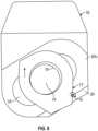
clip 16 has been slid as far as possible in direction A towards therail 11, thenut 15 is hand-tightened to engage thewasher 17, whereupon thenut 15 can be further tightened using a spanner. This causes thenut 15 to frictionally engage the upper surface of thewasher 17, thereby causing thewasher 17 to rotate in the clockwise tightening direction about the longitudinal axis of thebolt 14 until the right-hand end of the outwardly-facing straightside edge surface 17S thereof abuts the frontside edge surface 24F of theupstanding wall formation 24 on the rear of theclip 16 at point A. - Further tightening of the
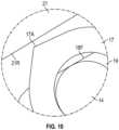
nut 15 now causes thewasher 17 to rotate in the clockwise direction about the abutment point A across the planar upper surface 20U of theclip 16 until the inner edge of thewasher aperture 19 abuts thebolt 14 and urges it against thefront side wall 18F of theelongate clip aperture 18, as shown inFigure 9B . Continued rotation of thenut 15 further rotates thewasher 17 about point A into a position in which thefront side wall 18F of theelongate clip aperture 18 extends as a chord across thewasher aperture 19, as shown inFigures 9C and10 . - In order to avoid any risk that the action of the
washer 17 pivoting against the frontside edge surface 24F of theupstanding wall formation 24 on theclip 16 will cause theclip 16 to be pulled rearwardly away from the rail, theclip 16 can be urged forwardly following rotation of thewasher 17, by striking the rear end thereof with a hammer or other object, before thenut 15 is fully tightened. - In use, when a load on the
rail 11 acts to displace theclip 16 rearwardly, the force is immediately transferred to thebolt 14 because thewasher 17 has rotated into a position where it is away from the front load bearing face of thebolt 14 and where thefront side wall 18F of theclip aperture 18 can directly bear against thebolt 14. In this manner, no load is applied to thewasher 14 and the risk of thewasher 17 breaking under applied loads is avoided. Also, theprojection 18X on thefront side wall 18F of theclip aperture 18 forms the point of contact with thebolt 14, thereby ensuring that the force applied to thebolt 14 is applied close to where it is anchored and thus the risk of bending thebolt 15 is avoided. - A rail fastening device in accordance with the present invention is simple and inexpensive in construction and comprises a
clip 16 and awasher 17 for fastening to arail support 12 by anupstanding bolt 14 having anut 15, which can be tightened to lock thedevice 10 in position. Theclip 16 andwasher 17 compriserespective apertures bolt 14. Thewasher 17 is adapted to rotate as thenut 15 is tightened until a formation on thewasher 17 abuts anupstanding formation 24 on the rear of theclip 16 at point A, whereupon continued tightening of thenut 15 causes thewasher 17 to pivot at point A around an offset axis, so as to bring thebolt 14 into contact with afront surface 18F of theclip aperture 18. Further tightening of thenut 15 pivots thewasher 17 to a point where any displacement force applied to theclip 16 by the rail is applied directly to thebolt 14 and not to thewasher 17. In this manner, the risk of the washer failing, or bolt 14 bending is avoided.
Claims (15)
- A rail fastening device (10) comprising a clip (16) having a front, a rear and opposite sides, the front side comprising a forwardly-projecting cap portion (21) adapted for abutment with a rail (11) to be fastened, the rear side comprising a body (20) having an elongate clip aperture (18) extending obliquely forwardly between the opposite sides towards the front side of the clip, the elongate clip aperture having a front side wall (18F) and a rear side wall (18R),the rail fastening device further comprising a washer (17) which is slidable along a substantially planar upper surface (20U) of the body of the clip surrounding the elongate clip aperture, the washer having an aperture (19) and a side edge formation disposed radially outwardly of the aperture,characterised in that the washer is arranged such that said side edge formation thereof is free to abut an abutment point (A) on a rear upstanding formation (24) on a surface (24F) of the underlying clip which extends parallel to the elongate clip aperture, such that tightening of an elongate upstanding fastener (14) extending through the aligned apertures (18,19) of the clip and washer causes the washer to pivot forwardly across the substantially planar upper surface about said abutment point into a position in which the front side wall of the elongate clip aperture extends as a chord across the washer aperture (19).
- A rail fastening device as claimed in claim 1, in which the front side wall of the elongate clip aperture is profiled to provide a projection (18X) which extends into the aperture at a point below the upper end of the aperture.
- A rail fastening device as claimed in claim 2, in which the projection extends into the elongate clip aperture (18) at a point that is more adjacent the lower end of the aperture than the upper end.
- A rail fastening device as claimed in any preceding claim, in which the substantially planar upper surface (20U) of the body of the clip surrounding the elongate clip aperture is inclined upwardly from the rear side towards the front side of the clip.
- A rail fastening device as claimed in claim 4, in which the washer (17) comprises a bottom surface which is inclined at a complementary angle to the upper surface of the clip, such that in use the upper surface of the washer lies in a plane which extends normal to the axis of the elongate upstanding fastener (14).
- A rail fastening device as claimed in any preceding claim, in which the washer comprises an outwardly-facing straight side edge surface (17S) the abutment point (A) being provided by one end of the outwardly-facing straight side edge surface.
- A rail fastening device as claimed in any preceding claim, in which the rear upstanding formation on the surface of the clip comprises a straight side edge surface (24F) which faces towards and extends parallel to the elongate clip aperture.
- A rail fastening device as claimed in any preceding claim, in which the washer comprises a projection (17P) which extends outwardly of the outwardly-facing straight side edge surface over the rear upstanding formation on the surface of the clip.
- A method of fastening a rail in position using a rail fastening device (10) as claimed in any preceding claim, the method comprising engaging the clip (16) and the washer (17) with the elongate upstanding fastener (14) for securing the rail fastening device in position, sliding the clip towards the rail, rotating an upper end portion of the rail fastening device in a tightening direction until it abuts the upper surface of the washer, and causing the washer to pivot forwardly across the substantially planar upper surface (20U) of the clip about said abutment point (A) into a position in which the front side wall (18F) of the elongate clip aperture (18) extends as a chord across the washer aperture.
- A method as claimed in claim 9, in which the washer is caused to pivot to move the elongate upstanding fastener relative to the clip in a direction which brings the elongate upstanding fastener (14) into contact with the front side wall of the elongate clip aperture.
- A method as claimed in claim 9 or claim 10, in which the rail fastening device comprises an externally threaded shaft extending upwardly from a support surface, the method comprising rotating a nut (15) that is threadably mounted on the externally threaded shaft.
- A method as claimed in any of claims 9 to 11, in which the rail fastening device comprises a bolt (14) having an externally threaded shaft which extends into an internally threaded member fixed to a support surface, the method comprising rotating a head of the bolt.
- A method as claimed in any of claims 9 to 12, in which the clip (16) is urged forwardly following rotation of the washer.
- A method as claimed in claim 13, in which the clip (16) is urged forwardly by striking the rear side thereof with an object.
- A method as claimed in claim 13, in which the elongate upstanding fastener (14) is further tightened following urging the clip forwardly.
Applications Claiming Priority (2)
| Application Number | Priority Date | Filing Date | Title |
|---|---|---|---|
| GB1912155.7AGB2586510A (en) | 2019-08-23 | 2019-08-23 | Rail fastening device |
| PCT/GB2020/051703WO2021038185A1 (en) | 2019-08-23 | 2020-07-15 | Rail fastening device |
Publications (3)
| Publication Number | Publication Date |
|---|---|
| EP4018039A1 EP4018039A1 (en) | 2022-06-29 |
| EP4018039B1true EP4018039B1 (en) | 2023-09-13 |
| EP4018039C0 EP4018039C0 (en) | 2023-09-13 |
Family
ID=68108781
Family Applications (1)
| Application Number | Title | Priority Date | Filing Date |
|---|---|---|---|
| EP20747083.2AActiveEP4018039B1 (en) | 2019-08-23 | 2020-07-15 | Rail fastening device |
Country Status (6)
| Country | Link |
|---|---|
| US (1) | US20220282430A1 (en) |
| EP (1) | EP4018039B1 (en) |
| CN (1) | CN114375357B (en) |
| AU (1) | AU2020339772A1 (en) |
| GB (1) | GB2586510A (en) |
| WO (1) | WO2021038185A1 (en) |
Family Cites Families (22)
| Publication number | Priority date | Publication date | Assignee | Title |
|---|---|---|---|---|
| GB1599873A (en)* | 1977-04-19 | 1981-10-07 | Kins Developments Ltd | Rail clip assemblies |
| ZA823358B (en)* | 1982-01-25 | 1983-04-27 | Omark Australia Ltd | Rail fastening means |
| JPS5921801A (en)* | 1982-07-28 | 1984-02-03 | 奥村 修一 | Rail clamp apparatus |
| US4489885A (en)* | 1982-08-02 | 1984-12-25 | Dayco Corporation | Rail fastening system |
| CA1285254C (en)* | 1985-02-01 | 1991-06-25 | Hartley F. Young | Rail fastening systems |
| DE8533479U1 (en)* | 1985-11-28 | 1986-01-16 | Minner, Hans K., Dipl.-Ing., 2000 Hamburg | Fastening device for running rails |
| GB8620832D0 (en)* | 1986-08-28 | 1986-10-08 | Cranequip Ltd | Rail clip assembly |
| US4967954A (en)* | 1988-12-15 | 1990-11-06 | American Track Systems, Inc. | Rail fastening device |
| GB9701233D0 (en)* | 1997-01-22 | 1997-03-12 | Molyneux Godfrey M O | Smaller,more efficient,adjustable anchorage for crane rails |
| EP1013827A1 (en)* | 1998-12-23 | 2000-06-28 | Gantry S.A. | Rail fastenings |
| FR2959249B1 (en)* | 2010-04-23 | 2012-11-02 | Railtech Int | RAIL FASTENING SYSTEM WITH ELASTIC ATTACHMENT |
| ES2533994T3 (en)* | 2010-07-19 | 2015-04-16 | Schwihag Ag | Rail fixing system |
| GB2502990B (en)* | 2012-06-12 | 2018-01-31 | Pandrol Ltd | Railway rail fastening clip for recessed railseats |
| CN103508316B (en)* | 2012-06-28 | 2016-07-06 | 纪军付 | A kind of binary device for fixing running tracks |
| GB2510419B (en)* | 2013-02-04 | 2020-02-05 | Pandrol Ltd | A railway rail anchoring device |
| BR112016025336B1 (en)* | 2014-04-28 | 2022-05-10 | Hf Holding S.A. | rail clamp set |
| GB2530100B (en)* | 2014-09-15 | 2018-09-12 | Gantry Railing Ltd | Rail member and rail system |
| GB2538799A (en)* | 2015-05-29 | 2016-11-30 | Airbus Operations Ltd | Fastening device |
| GB201513369D0 (en)* | 2015-07-29 | 2015-09-09 | Gantry Railing Ltd | Rail fastening device |
| GB201610661D0 (en)* | 2016-06-17 | 2016-08-03 | Gantry Railing Ltd | Rail Fastening Device |
| GB2591259B (en)* | 2020-01-22 | 2022-11-23 | Gantry Railing Ltd | Clamp device |
| CN217710108U (en)* | 2021-05-26 | 2022-11-01 | 瑞泰潘得路铁路技术(武汉)有限公司 | Rail fastening assembly |
- 2019
- 2019-08-23GBGB1912155.7Apatent/GB2586510A/ennot_activeWithdrawn
- 2020
- 2020-07-15CNCN202080059635.2Apatent/CN114375357B/enactiveActive
- 2020-07-15EPEP20747083.2Apatent/EP4018039B1/enactiveActive
- 2020-07-15AUAU2020339772Apatent/AU2020339772A1/enactivePending
- 2020-07-15USUS17/634,546patent/US20220282430A1/enactivePending
- 2020-07-15WOPCT/GB2020/051703patent/WO2021038185A1/ennot_activeCeased
Also Published As
| Publication number | Publication date |
|---|---|
| EP4018039A1 (en) | 2022-06-29 |
| CN114375357B (en) | 2023-12-08 |
| GB201912155D0 (en) | 2019-10-09 |
| CN114375357A (en) | 2022-04-19 |
| AU2020339772A1 (en) | 2022-02-17 |
| GB2586510A (en) | 2021-02-24 |
| EP4018039C0 (en) | 2023-09-13 |
| WO2021038185A1 (en) | 2021-03-04 |
| US20220282430A1 (en) | 2022-09-08 |
Similar Documents
| Publication | Publication Date | Title |
|---|---|---|
| US7604444B2 (en) | Fastener assembly | |
| US8920089B1 (en) | Device for securing a panel to a mounting stud | |
| JP3051260B2 (en) | One-line arrangement and fixing device for rail | |
| US20110027039A1 (en) | Lock Washer | |
| US4221252A (en) | Locking arrangement particularly for shackles | |
| CN109311638B (en) | Rail fixing device | |
| US6928783B2 (en) | Frame clamp for anchor strap | |
| EP4018039B1 (en) | Rail fastening device | |
| US4472917A (en) | Fixing device for mounting a plate on the flange of a beam | |
| US4041833A (en) | Cap assembly for a nut and bolt | |
| US20100011693A1 (en) | Shear plate | |
| JP2000039010A (en) | Protection device for bolt and nut joints of steel towers | |
| JP5038801B2 (en) | Lining board mounting structure | |
| US6554554B1 (en) | Tilt action fastener | |
| JP6703178B1 (en) | Lining plate mounting structure | |
| EP0344862A1 (en) | Pipe-clip | |
| JPS63259207A (en) | Tightening bands and tightening tools | |
| CA1201313A (en) | fixing device | |
| AU2007214295B2 (en) | Shear plate | |
| AU738440B2 (en) | Threaded fastener with a tilting, self-locking nut | |
| JP2017040098A (en) | Method for manufacturing lining plate fastening device and lining plate fastening method |
Legal Events
| Date | Code | Title | Description |
|---|---|---|---|
| STAA | Information on the status of an ep patent application or granted ep patent | Free format text:STATUS: UNKNOWN | |
| STAA | Information on the status of an ep patent application or granted ep patent | Free format text:STATUS: THE INTERNATIONAL PUBLICATION HAS BEEN MADE | |
| PUAI | Public reference made under article 153(3) epc to a published international application that has entered the european phase | Free format text:ORIGINAL CODE: 0009012 | |
| STAA | Information on the status of an ep patent application or granted ep patent | Free format text:STATUS: REQUEST FOR EXAMINATION WAS MADE | |
| 17P | Request for examination filed | Effective date:20220118 | |
| AK | Designated contracting states | Kind code of ref document:A1 Designated state(s):AL AT BE BG CH CY CZ DE DK EE ES FI FR GB GR HR HU IE IS IT LI LT LU LV MC MK MT NL NO PL PT RO RS SE SI SK SM TR | |
| DAV | Request for validation of the european patent (deleted) | ||
| DAX | Request for extension of the european patent (deleted) | ||
| GRAP | Despatch of communication of intention to grant a patent | Free format text:ORIGINAL CODE: EPIDOSNIGR1 | |
| STAA | Information on the status of an ep patent application or granted ep patent | Free format text:STATUS: GRANT OF PATENT IS INTENDED | |
| INTG | Intention to grant announced | Effective date:20230417 | |
| GRAS | Grant fee paid | Free format text:ORIGINAL CODE: EPIDOSNIGR3 | |
| GRAA | (expected) grant | Free format text:ORIGINAL CODE: 0009210 | |
| STAA | Information on the status of an ep patent application or granted ep patent | Free format text:STATUS: THE PATENT HAS BEEN GRANTED | |
| AK | Designated contracting states | Kind code of ref document:B1 Designated state(s):AL AT BE BG CH CY CZ DE DK EE ES FI FR GB GR HR HU IE IS IT LI LT LU LV MC MK MT NL NO PL PT RO RS SE SI SK SM TR | |
| REG | Reference to a national code | Ref country code:CH Ref legal event code:EP | |
| REG | Reference to a national code | Ref country code:DE Ref legal event code:R096 Ref document number:602020017680 Country of ref document:DE | |
| REG | Reference to a national code | Ref country code:IE Ref legal event code:FG4D | |
| U01 | Request for unitary effect filed | Effective date:20230913 | |
| U07 | Unitary effect registered | Designated state(s):AT BE BG DE DK EE FI FR IT LT LU LV MT NL PT SE SI Effective date:20230920 | |
| PG25 | Lapsed in a contracting state [announced via postgrant information from national office to epo] | Ref country code:GR Free format text:LAPSE BECAUSE OF FAILURE TO SUBMIT A TRANSLATION OF THE DESCRIPTION OR TO PAY THE FEE WITHIN THE PRESCRIBED TIME-LIMIT Effective date:20231214 | |
| PG25 | Lapsed in a contracting state [announced via postgrant information from national office to epo] | Ref country code:RS Free format text:LAPSE BECAUSE OF FAILURE TO SUBMIT A TRANSLATION OF THE DESCRIPTION OR TO PAY THE FEE WITHIN THE PRESCRIBED TIME-LIMIT Effective date:20230913 Ref country code:NO Free format text:LAPSE BECAUSE OF FAILURE TO SUBMIT A TRANSLATION OF THE DESCRIPTION OR TO PAY THE FEE WITHIN THE PRESCRIBED TIME-LIMIT Effective date:20231213 Ref country code:HR Free format text:LAPSE BECAUSE OF FAILURE TO SUBMIT A TRANSLATION OF THE DESCRIPTION OR TO PAY THE FEE WITHIN THE PRESCRIBED TIME-LIMIT Effective date:20230913 Ref country code:GR Free format text:LAPSE BECAUSE OF FAILURE TO SUBMIT A TRANSLATION OF THE DESCRIPTION OR TO PAY THE FEE WITHIN THE PRESCRIBED TIME-LIMIT Effective date:20231214 | |
| PG25 | Lapsed in a contracting state [announced via postgrant information from national office to epo] | Ref country code:IS Free format text:LAPSE BECAUSE OF FAILURE TO SUBMIT A TRANSLATION OF THE DESCRIPTION OR TO PAY THE FEE WITHIN THE PRESCRIBED TIME-LIMIT Effective date:20240113 | |
| PG25 | Lapsed in a contracting state [announced via postgrant information from national office to epo] | Ref country code:ES Free format text:LAPSE BECAUSE OF FAILURE TO SUBMIT A TRANSLATION OF THE DESCRIPTION OR TO PAY THE FEE WITHIN THE PRESCRIBED TIME-LIMIT Effective date:20230913 | |
| PG25 | Lapsed in a contracting state [announced via postgrant information from national office to epo] | Ref country code:SM Free format text:LAPSE BECAUSE OF FAILURE TO SUBMIT A TRANSLATION OF THE DESCRIPTION OR TO PAY THE FEE WITHIN THE PRESCRIBED TIME-LIMIT Effective date:20230913 Ref country code:RO Free format text:LAPSE BECAUSE OF FAILURE TO SUBMIT A TRANSLATION OF THE DESCRIPTION OR TO PAY THE FEE WITHIN THE PRESCRIBED TIME-LIMIT Effective date:20230913 Ref country code:IS Free format text:LAPSE BECAUSE OF FAILURE TO SUBMIT A TRANSLATION OF THE DESCRIPTION OR TO PAY THE FEE WITHIN THE PRESCRIBED TIME-LIMIT Effective date:20240113 Ref country code:ES Free format text:LAPSE BECAUSE OF FAILURE TO SUBMIT A TRANSLATION OF THE DESCRIPTION OR TO PAY THE FEE WITHIN THE PRESCRIBED TIME-LIMIT Effective date:20230913 Ref country code:CZ Free format text:LAPSE BECAUSE OF FAILURE TO SUBMIT A TRANSLATION OF THE DESCRIPTION OR TO PAY THE FEE WITHIN THE PRESCRIBED TIME-LIMIT Effective date:20230913 Ref country code:SK Free format text:LAPSE BECAUSE OF FAILURE TO SUBMIT A TRANSLATION OF THE DESCRIPTION OR TO PAY THE FEE WITHIN THE PRESCRIBED TIME-LIMIT Effective date:20230913 | |
| PG25 | Lapsed in a contracting state [announced via postgrant information from national office to epo] | Ref country code:PL Free format text:LAPSE BECAUSE OF FAILURE TO SUBMIT A TRANSLATION OF THE DESCRIPTION OR TO PAY THE FEE WITHIN THE PRESCRIBED TIME-LIMIT Effective date:20230913 | |
| REG | Reference to a national code | Ref country code:DE Ref legal event code:R097 Ref document number:602020017680 Country of ref document:DE | |
| U20 | Renewal fee for the european patent with unitary effect paid | Year of fee payment:5 Effective date:20240521 | |
| PLBE | No opposition filed within time limit | Free format text:ORIGINAL CODE: 0009261 | |
| STAA | Information on the status of an ep patent application or granted ep patent | Free format text:STATUS: NO OPPOSITION FILED WITHIN TIME LIMIT | |
| 26N | No opposition filed | Effective date:20240614 | |
| PGFP | Annual fee paid to national office [announced via postgrant information from national office to epo] | Ref country code:TR Payment date:20240610 Year of fee payment:5 | |
| PG25 | Lapsed in a contracting state [announced via postgrant information from national office to epo] | Ref country code:MC Free format text:LAPSE BECAUSE OF FAILURE TO SUBMIT A TRANSLATION OF THE DESCRIPTION OR TO PAY THE FEE WITHIN THE PRESCRIBED TIME-LIMIT Effective date:20230913 | |
| REG | Reference to a national code | Ref country code:CH Ref legal event code:PL | |
| PG25 | Lapsed in a contracting state [announced via postgrant information from national office to epo] | Ref country code:CH Free format text:LAPSE BECAUSE OF NON-PAYMENT OF DUE FEES Effective date:20240731 | |
| U20 | Renewal fee for the european patent with unitary effect paid | Year of fee payment:6 Effective date:20250520 | |
| PGFP | Annual fee paid to national office [announced via postgrant information from national office to epo] | Ref country code:GB Payment date:20250520 Year of fee payment:6 | |
| PG25 | Lapsed in a contracting state [announced via postgrant information from national office to epo] | Ref country code:IE Free format text:LAPSE BECAUSE OF NON-PAYMENT OF DUE FEES Effective date:20240715 |