EP4012328B1 - System and method of optical scanning of a vehicle for measuring and/or controlling the vehicle and/or parts thereof - Google Patents
System and method of optical scanning of a vehicle for measuring and/or controlling the vehicle and/or parts thereofDownload PDFInfo
- Publication number
- EP4012328B1 EP4012328B1EP21213897.8AEP21213897AEP4012328B1EP 4012328 B1EP4012328 B1EP 4012328B1EP 21213897 AEP21213897 AEP 21213897AEP 4012328 B1EP4012328 B1EP 4012328B1
- Authority
- EP
- European Patent Office
- Prior art keywords
- vehicle
- optical
- image capturing
- optical image
- target
- Prior art date
- Legal status (The legal status is an assumption and is not a legal conclusion. Google has not performed a legal analysis and makes no representation as to the accuracy of the status listed.)
- Active
Links
Images

Classifications
- G—PHYSICS
- G01—MEASURING; TESTING
- G01B—MEASURING LENGTH, THICKNESS OR SIMILAR LINEAR DIMENSIONS; MEASURING ANGLES; MEASURING AREAS; MEASURING IRREGULARITIES OF SURFACES OR CONTOURS
- G01B11/00—Measuring arrangements characterised by the use of optical techniques
- G01B11/26—Measuring arrangements characterised by the use of optical techniques for measuring angles or tapers; for testing the alignment of axes
- G01B11/275—Measuring arrangements characterised by the use of optical techniques for measuring angles or tapers; for testing the alignment of axes for testing wheel alignment
- G—PHYSICS
- G06—COMPUTING OR CALCULATING; COUNTING
- G06T—IMAGE DATA PROCESSING OR GENERATION, IN GENERAL
- G06T7/00—Image analysis
- G06T7/80—Analysis of captured images to determine intrinsic or extrinsic camera parameters, i.e. camera calibration
- G06T7/85—Stereo camera calibration
- G—PHYSICS
- G01—MEASURING; TESTING
- G01B—MEASURING LENGTH, THICKNESS OR SIMILAR LINEAR DIMENSIONS; MEASURING ANGLES; MEASURING AREAS; MEASURING IRREGULARITIES OF SURFACES OR CONTOURS
- G01B11/00—Measuring arrangements characterised by the use of optical techniques
- G01B11/24—Measuring arrangements characterised by the use of optical techniques for measuring contours or curvatures
- G—PHYSICS
- G01—MEASURING; TESTING
- G01B—MEASURING LENGTH, THICKNESS OR SIMILAR LINEAR DIMENSIONS; MEASURING ANGLES; MEASURING AREAS; MEASURING IRREGULARITIES OF SURFACES OR CONTOURS
- G01B11/00—Measuring arrangements characterised by the use of optical techniques
- G01B11/26—Measuring arrangements characterised by the use of optical techniques for measuring angles or tapers; for testing the alignment of axes
- G01B11/275—Measuring arrangements characterised by the use of optical techniques for measuring angles or tapers; for testing the alignment of axes for testing wheel alignment
- G01B11/2755—Measuring arrangements characterised by the use of optical techniques for measuring angles or tapers; for testing the alignment of axes for testing wheel alignment using photoelectric detection means
- G—PHYSICS
- G01—MEASURING; TESTING
- G01M—TESTING STATIC OR DYNAMIC BALANCE OF MACHINES OR STRUCTURES; TESTING OF STRUCTURES OR APPARATUS, NOT OTHERWISE PROVIDED FOR
- G01M17/00—Testing of vehicles
- G01M17/007—Wheeled or endless-tracked vehicles
- G—PHYSICS
- G01—MEASURING; TESTING
- G01S—RADIO DIRECTION-FINDING; RADIO NAVIGATION; DETERMINING DISTANCE OR VELOCITY BY USE OF RADIO WAVES; LOCATING OR PRESENCE-DETECTING BY USE OF THE REFLECTION OR RERADIATION OF RADIO WAVES; ANALOGOUS ARRANGEMENTS USING OTHER WAVES
- G01S17/00—Systems using the reflection or reradiation of electromagnetic waves other than radio waves, e.g. lidar systems
- G01S17/88—Lidar systems specially adapted for specific applications
- G01S17/89—Lidar systems specially adapted for specific applications for mapping or imaging
- G01S17/894—3D imaging with simultaneous measurement of time-of-flight at a 2D array of receiver pixels, e.g. time-of-flight cameras or flash lidar
- G—PHYSICS
- G01—MEASURING; TESTING
- G01S—RADIO DIRECTION-FINDING; RADIO NAVIGATION; DETERMINING DISTANCE OR VELOCITY BY USE OF RADIO WAVES; LOCATING OR PRESENCE-DETECTING BY USE OF THE REFLECTION OR RERADIATION OF RADIO WAVES; ANALOGOUS ARRANGEMENTS USING OTHER WAVES
- G01S7/00—Details of systems according to groups G01S13/00, G01S15/00, G01S17/00
- G01S7/48—Details of systems according to groups G01S13/00, G01S15/00, G01S17/00 of systems according to group G01S17/00
- G01S7/497—Means for monitoring or calibrating
- G—PHYSICS
- G06—COMPUTING OR CALCULATING; COUNTING
- G06T—IMAGE DATA PROCESSING OR GENERATION, IN GENERAL
- G06T7/00—Image analysis
- G06T7/60—Analysis of geometric attributes
- G—PHYSICS
- G06—COMPUTING OR CALCULATING; COUNTING
- G06T—IMAGE DATA PROCESSING OR GENERATION, IN GENERAL
- G06T7/00—Image analysis
- G06T7/70—Determining position or orientation of objects or cameras
- H—ELECTRICITY
- H04—ELECTRIC COMMUNICATION TECHNIQUE
- H04N—PICTORIAL COMMUNICATION, e.g. TELEVISION
- H04N13/00—Stereoscopic video systems; Multi-view video systems; Details thereof
- H04N13/20—Image signal generators
- H04N13/204—Image signal generators using stereoscopic image cameras
- H04N13/239—Image signal generators using stereoscopic image cameras using two 2D image sensors having a relative position equal to or related to the interocular distance
- H—ELECTRICITY
- H04—ELECTRIC COMMUNICATION TECHNIQUE
- H04N—PICTORIAL COMMUNICATION, e.g. TELEVISION
- H04N13/00—Stereoscopic video systems; Multi-view video systems; Details thereof
- H04N13/20—Image signal generators
- H04N13/204—Image signal generators using stereoscopic image cameras
- H04N13/254—Image signal generators using stereoscopic image cameras in combination with electromagnetic radiation sources for illuminating objects
- H—ELECTRICITY
- H04—ELECTRIC COMMUNICATION TECHNIQUE
- H04N—PICTORIAL COMMUNICATION, e.g. TELEVISION
- H04N13/00—Stereoscopic video systems; Multi-view video systems; Details thereof
- H04N13/20—Image signal generators
- H04N13/296—Synchronisation thereof; Control thereof
- G—PHYSICS
- G01—MEASURING; TESTING
- G01B—MEASURING LENGTH, THICKNESS OR SIMILAR LINEAR DIMENSIONS; MEASURING ANGLES; MEASURING AREAS; MEASURING IRREGULARITIES OF SURFACES OR CONTOURS
- G01B2210/00—Aspects not specifically covered by any group under G01B, e.g. of wheel alignment, caliper-like sensors
- G01B2210/10—Wheel alignment
- G01B2210/12—Method or fixture for calibrating the wheel aligner
- G—PHYSICS
- G01—MEASURING; TESTING
- G01B—MEASURING LENGTH, THICKNESS OR SIMILAR LINEAR DIMENSIONS; MEASURING ANGLES; MEASURING AREAS; MEASURING IRREGULARITIES OF SURFACES OR CONTOURS
- G01B2210/00—Aspects not specifically covered by any group under G01B, e.g. of wheel alignment, caliper-like sensors
- G01B2210/10—Wheel alignment
- G01B2210/14—One or more cameras or other optical devices capable of acquiring a two-dimensional image
- G01B2210/143—One or more cameras on each side of a vehicle in the main embodiment
- G—PHYSICS
- G01—MEASURING; TESTING
- G01B—MEASURING LENGTH, THICKNESS OR SIMILAR LINEAR DIMENSIONS; MEASURING ANGLES; MEASURING AREAS; MEASURING IRREGULARITIES OF SURFACES OR CONTOURS
- G01B2210/00—Aspects not specifically covered by any group under G01B, e.g. of wheel alignment, caliper-like sensors
- G01B2210/10—Wheel alignment
- G01B2210/14—One or more cameras or other optical devices capable of acquiring a two-dimensional image
- G01B2210/146—Two or more cameras imaging the same area
- G—PHYSICS
- G01—MEASURING; TESTING
- G01B—MEASURING LENGTH, THICKNESS OR SIMILAR LINEAR DIMENSIONS; MEASURING ANGLES; MEASURING AREAS; MEASURING IRREGULARITIES OF SURFACES OR CONTOURS
- G01B2210/00—Aspects not specifically covered by any group under G01B, e.g. of wheel alignment, caliper-like sensors
- G01B2210/10—Wheel alignment
- G01B2210/30—Reference markings, reflector, scale or other passive device
- G01B2210/303—Reference markings, reflector, scale or other passive device fixed to the ground or to the measuring station
- G—PHYSICS
- G01—MEASURING; TESTING
- G01M—TESTING STATIC OR DYNAMIC BALANCE OF MACHINES OR STRUCTURES; TESTING OF STRUCTURES OR APPARATUS, NOT OTHERWISE PROVIDED FOR
- G01M17/00—Testing of vehicles
- H—ELECTRICITY
- H04—ELECTRIC COMMUNICATION TECHNIQUE
- H04N—PICTORIAL COMMUNICATION, e.g. TELEVISION
- H04N2213/00—Details of stereoscopic systems
- H04N2213/001—Constructional or mechanical details
Definitions
- the inventionrelates to a vehicle optical scanning system and method for measuring/controlling the vehicle and/or parts of the vehicle.
- the inventiondeals with the calibration of an optical scanning system for measuring and/or controlling a vehicle and/or parts thereof.
- Systemswhich are designed to carry out an optical scanning of a vehicle so as to obtain three-dimensional images of the vehicle and/or of parts thereof.
- optical scanning systemsare used to capture three-dimensional images of the lateral sides of the vehicle in order to determine, based on the captured images, geometric parameters concerning the parts making up the vehicle corresponding, for example, to the wheels and/or the steering and/or the axles of the vehicle.
- geometric parametersare generally determined, which comprise the angles of the wheels and/or of the steering and/or of the axles, which characterise the so-called "attitude" of the vehicle. More in detail, in optical scanning systems used to determine the attitude of the wheels of the vehicle, the angle of attack, the camber angle and the toe-in angle of the wheels are determined and said measured angles are compared with corresponding reference angles associated with a correct attitude condition. Based on the outcome of the comparison, it is determined whether it is necessary or unnecessary to mechanically intervene in order to adjust the angular position of the wheels so as to comply with a correct attitude condition.
- Some optical scanning systems used to determine the attitude of the wheelscommonly comprise three-dimensional optical image readers, which are arranged so as to face the two lateral opposite sides of the vehicle and are configured to carry out an optical scanning of the lateral sides of the vehicle in order to obtain a tree-dimensional digital representation thereof, from which to obtain a digital image representation and/or a geometric representation of the wheels of the vehicle.
- the systemis able to determine the correctness of the vehicle attitude or the lack thereof.
- the systems described abovehave to geometrically characterise the mutual positioning and the visual field of three-dimensional optical readers relative to a common reference system.
- the optical scanning systems described aboverequire an initial calibration, during which the aforesaid geometrical parameters of the three-dimensional optical readers are determined with precision.
- some optical scanning systemsare provided with calibration systems, which detect the movements of the three-dimensional optical readers relative to the data detected during the calibration phase and recalibrate them based on the detected movements.
- Some calibration systemsuch as the one described in EP 2 769 177 B1 , involve the use of reference targets, which are vertically fixed on the three-dimensional optical reader.
- a first optical readeris placed in the control station next to the vehicle so as to frame the target fixed on an opposite second optical reader and the calibration of the first optical reader is carried out based on the image of the fixed target present on the second optical reader.
- a technical problem affecting calibration systems of the type described abovelies in the fact that these systems are not suitable for calibrating an optical reader when the vehicle is standing in the control station between the optical readers. In this condition, the vehicle is interposed between the optical reader and the reference target fixed on the other optical reader. Therefore, the control station has to be free from vehicles, a condition that is not always appreciated by mechanical operators taking care of the control of the vehicle.
- the object of the inventionis to provide an optical scanning method and system for measuring and/or controlling the vehicle and/or parts of the vehicle, which overcome the technical problem described above and fulfil the needs discussed above.
- number 1indicates, as a whole, an optical scanning system for a vehicle 2 for measuring and/or controlling the vehicle 2 and/or parts/components of the vehicle 2.
- the vehicle 2is arranged in a control station, which comprises a plane, on which, in use, the wheels 3 of the vehicle 2 rest.
- the planecan correspond, for example, to the support surface, for instance a horizontal one.
- the support surfacecan correspond to a floor/ground present in the vehicle control station, for example inside a vehicle service department (which is not shown herein).
- the planecan comprise any plane on which the wheels 3 of the vehicle 2 rest.
- the vehicle 2can be a motor vehicle with an engine, in particular a car, and, in the example shown in Figures 1 , 6 and 7 , it centrally has a longitudinal reference axis A and is provided with four wheels 3 coupled, in pairs, to two corresponding axles, namely a front axle V1 and a rear axle V2, of the vehicle 2, which are transverse to the axis A (namely, orthogonal thereto in the accompanying Figures) and are at a given axle base distance from one another (measured along the axis A).
- the optical scanning system 1is designed to determine a series of geometric parameters characterising the vehicle 2 and/or parts/components thereof.
- the geometric parameters of the parts/components of the vehiclecan, for example, relate to: the wheels 3 and/or the axles V1, V2 and/or the steering (which is not shown herein).
- the geometric parameters of the wheels 3can comprise, for example: the angle or plane of attack of the wheel, the camber angle of the wheel, the toe angle or plane of the wheel.
- the angles or planescan preferably be determined relative to at least one predetermined three-dimensional reference system SR.
- the geometric parameters characterising the wheels 3 used in the optical scanning system 1 for the control, for example, of the wheel attitude of the vehicle 2are known and, therefore, will not be discussed any further.
- optical scanning system 1is not limited to the determination of the above-mentioned geometric parameters for the control of the wheel attitude of the vehicle 2, but, in addition and/or alternatively, it can involve the determination of other pieces of information concerning the vehicle 2. These pieces of information can comprise, for instance, the position of the vehicle 2 within the vehicle control station P relative to the predetermined three-dimensional reference system SR.
- the optical scanning system 1can be designed to determine the position of the vehicle 2 relative to the predetermined reference system SR based on the images of the axles V1 and/or V2 and/or of the wheels 3.
- the optical scanning system 1can be configured to communicate (for example, through wireless communication) data/signals indicative of the position of the vehicle 2 relative to a predetermined reference system SR to one or more vehicle analysis/diagnosis systems (which are not shown herein).
- a vehicle analysis/diagnosis systemscan comprise a vehicle ADAS sensor control and/or calibration system (not shown), which is designed to control and/or calibrate advanced driver-assistance systems (ADAS) present in the vehicle 2.
- ADASadvanced driver-assistance systems
- This control and/or calibration systemis placed in the control station P, preferably in front of the vehicle 2,
- the vehicle ADAS sensor control and/or calibration systemcan receive the data/signals indicative of the position of the vehicle and determine its distance from the vehicle 2 based on its own position relative to the predetermined reference system SR of the optical scanning system 1 and on the received position of the vehicle 2.
- the optical scanning system 1comprises optical image reader apparatuses 4.
- the optical scanning system 1comprises two optical image reader apparatuses 4, which are arranged so as to be opposite one another on opposite sides of the vehicle 2, on the periphery thereof.
- the two optical image reader apparatuses 4are arranged on a surface P.
- the support surface P of the two optical image reader apparatuses 4is approximately coplanar to the support surface PV of the vehicle 2.
- the surface Pcould not be coplanar and/or parallel to the support surface PV of the vehicle 2.
- the optical image reader apparatuses 4are arranged so as to face two corresponding sides (lateral flanks) of the vehicle 2, which are parallel to and opposite relative to the axis A.
- the optical image reader apparatuses 4are arranged so as to face the two sides of the vehicle 2 approximately in the area of the middle axis of the vehicle 2.
- the optical image reader apparatuses 4can be arranged so as to face the wheels 3 of the vehicle 2.
- the optical image reader apparatuses 4are provided with respective optical image capturing devices 9 (described in detail below), which are configured to provide respective data/signals encoding one or more images entirely - or at least partially - representing the opposite sides of the vehicle 2 relative to the axis A.
- the optical scanning system 1further comprises a control and processing system 5, which is designed to process the data/signals provided by the optical image capturing devices 9 in order to determine/construct 3D (three-dimensional) images of the vehicle 2 and/or of parts thereof, by means of artificial vision algorithms, based on said data/signals.
- the aforesaid artificial vision algorithmsare known and, as a consequence, will not be described any further.
- the optical image reader apparatuses 4each comprise a target 6 (or calibration target), which lies on the plane K ( Figures 2 and 3 ) and is arranged immediately adjacent to the optical image capturing device 9 of the relative optical image reader apparatus 4.
- the target 6is arranged on the reference plane K at a predetermined distance D1 from the relative optical image capturing device 9.
- the target 6is arranged on the reference plane K so that it can be framed/visualized by the relative optical image capturing device 9.
- the reference plane Kis approximately horizontal.
- the target 6can conveniently be arranged between the optical image capturing device and the side of the vehicle 2 facing the optical image capturing device 9. It is understood that according to the invention, the target 6 can be placed in any superficial position of the reference plane K that surrounds the image capturing device 9 and is immediately adjacent thereto so that it can be framed/visualized.
- the electronic processing and control system 5is designed to calibrate the optical image reader apparatuses 4 based on the images of the respective targets 6.
- the Applicantfound out that, by placing the target 6 directly close to the optical image capturing device 9 at a predetermined fixed distance D1 and by processing the image of the target 6 itself, a calibration of the optical image reader apparatus 4 comprising the target 6 and the optical image capturing device 9 can be carried out, even when the vehicle 2 is interposed/standing between the optical image reader apparatuses 4.
- a calibration of the optical image reader apparatus 4comprising the target 6 and the optical image capturing device 9 can be carried out, even when the vehicle 2 is interposed/standing between the optical image reader apparatuses 4.
- each optical image reader apparatus 4further comprises a plate-shaped element 7, which has a longitudinal axis C.
- the plate-shaped element 7is arranged on the surface P and has, on its upper surface, the target 6. It is understood that the plate-shaped element 7 is arranged on a superficial portion of the surface on the periphery of the vehicle 2.
- the optical image reader apparatus 4further comprises a support column 8, which extends along a longitudinal axis B and is coupled to the plate-shaped element 7 in a position immediately adjacent to the target 6.
- the column 8can be coupled to the plate-shaped element 7 so that its longitudinal axis B is approximately orthogonal to the plate-shaped element 7 and to its axis C.
- the column 8supports at least one optical image capturing device 9.
- the optical image capturing device 9is arranged in the column 8 so as to frame and capture the image of the target 6 present on the underlying plate-shaped element 7.
- the upper surface of the plate-shaped element 7is approximately flat and forms the plane K on which the target 6 is arranged.
- the plate-shaped element 7further has a lower surface opposite the upper surface, which can be approximately flat. In the example shown in Figures 1-7 , said lower surface rests on the surface P and is firmly fixed/anchored to the latter.
- the plate-shaped element 7can comprise, for example, a flat plate or bracket made of a rigid material.
- Said rigid materialcan contain, for example, metal materials and/or polymer materials (plastic) or similar materials.
- the plate-shaped element 7has an approximately rectangular shape and has, at a first axial end, the target 6.
- the target 6is approximately planar, can comprise a two-dimensional (quadrangular) image representing a predetermined (calibration) pattern and is firmly fixed on the upper surface of the plate-shaped element 7 at its first axial end opposite the portion to which the support column 8 is coupled.
- the patterncomprises a geometry containing predetermined graphic elements (squares) in a (black and white) chessboard-like arrangement.
- the support column 8can comprise a tubular section bar.
- the tubular section bar 8can have a polygonal section crosswise to the axis B.
- the support column 8has a rectangular or square section and has four vertical rectangular faces parallel to the axis B.
- the upper end of the support column 8preferably is closed and shaped like a grip.
- the support column 8can have the lower end closed by a coupling plate 11.
- the coupling plate 11can conveniently be arranged orthogonal to the axis B.
- the coupling plate 11can have a flat polygonal shape (namely, a square or rectangular or hexagonal shape) and has, on at least one side, one or more sliding wheels 12.
- the wheels 12can preferably be cylindrical and be arranged on one side of the coupling plate 11.
- the coupling plate 11can be placed approximately on the second end of the plate-shaped element 7 opposite the first end accommodating the target 6 at a predetermined distance from the latter, so that the optical image capturing device 9 mounted in the column 8 is arranged at the predetermined distance D1 from the target 6.
- the technical effect of the wheels 12is that of facilitating the manual displacement of the optical image reader apparatus 4.
- the optical image reader apparatus 4can further conveniently comprise a connection device 13, which is structured to fix/anchor, in a stable yet easily separable/removable manner, the support column 8 to the plate-shaped element 7.
- connection element 13can comprise a magnetic coupling system 14 to magnetically couple/anchor the column 8 to the plate-shaped element 7.
- the magnetic coupling system 14can comprise, for example, one or more magnetic elements 14a with opposite magnetic poles, at least one of them being arranged on the second end of the plate-shaped element 7.
- Another magnetic element 14acan be arranged, for example, on the support column 8, preferably in the coupling plate 11.
- the connection device 13can comprise, instead of or in addition to the magnetic coupling system 14, mechanical coupling members 17, for example threaded joining elements (screws and/or nuts) or any similar mechanism, to anchor/fix the coupling plate 11 on the plate-shaped element 7.
- the optical image reader apparatus 4can further comprise a self-centring mechanism 15 to centre the coupling of the support column 8 on the second end of the plate-shaped element 7.
- the self-centring mechanism 15can comprise one or more projections or protuberances 16, which are arranged on the upper surface of the second end of the plate-shaped element 7 in predetermined points.
- the self-centring mechanism 15can comprise a series of seats (not shown herein), which are obtained on the lower surface of the coupling plate 11 and have a position and a shape that are complementary to the position and the shape of the projections 16 in order to accommodate them when the coupling plate 11 rests on the second end of the plate-shaped element 7.
- the projections 16 of the self-centring mechanism 15can conveniently be sized and structured so that the coupling plate 11, when in it is arranged on the predetermined portion of the plate-shaped element 7, remains in a horizontal position, slightly lifted from the upper surface of the underlying plate-shaped element 7 at a height that is such as to also keep the wheels 12 lifted and not in contact with the surface P.
- the optical image capturing device 9comprises at least one camera 9a.
- the optical image capturing device 9further comprises a camera 9b, which is arranged at a predetermined distance from the camera 9a.
- the cameras 9a and 9bcooperate with the processing and control system 5 so as to implement a binocular stereoscopic vision method.
- the operation of the binocular stereoscopic vision method by means of two cameras in order to construct a 3D imageis known and will not be described any further.
- the camera 9a and the camera 9bare firmly arranged in the support column 8 so that the relative optical assemblies (lenses) face and are oriented on a common face/side of the support column 8 so as to frame a side of the vehicle 2.
- the cameras 9a and 9bcan frame the side of the vehicle 2 through through openings made in the face/side of the column 8.
- the cameras 9a and 9bare arranged in the column 8 so as to be axially spaced apart from one another along the longitudinal axis B at said predetermined distance.
- the optical image capturing device 9can further comprise at least one light source 9c, which is designed to emit a light beam to irradiate the target 6.
- the camera 9ais arranged in the support column 8 in a lower intermediate position, above the coupling plate 11.
- the camera 9bis arranged in the support column 8 in an upper intermediate position, immediately under the upper end of the column 8 itself.
- the camera 9bis configured so as to frame both the side of the vehicle 2 and the target 6 present in the underlying plate-shaped element 7.
- the camera 9ais configured to frame the side of the vehicle 2.
- the inventionis not limited to an optical vision architecture that entails the use of cameras 9a and 9b to reconstruct three-dimensional images through the implementation of a binocular stereoscopic vision method, but, alternatively, other optical vision architectures can be used for the construction of a three-dimensional image.
- one or more camerascan be used, which are configured to carry out an optical image reading according to an optical vision architecture involving structured-light 3D scanning, which can entail the use of at least one projector (not shown) on the support column 8.
- the processing and control system 5can comprise one or more processing units 5a, which can conveniently be arranged inside the support columns 8.
- the processing units 5acan be configured to communicate with one another through a wireless communication system (which is not shown herein) in order to exchange the data/signals concerning the captured images.
- the processing system 5can further comprise, alternatively or in addition to the processing units 5s, a central processing unit 500.
- the processing units 5acan comprise microprocessors or similar electronic processing circuits, whereas the central the processing unit 500 can comprise a desktop computer or a laptop or any other similar processing device.
- the processing and control system 5can construct, by means of the cameras 9a and 9b, the three-dimensional image of the wheel 3, in which each point (pixel) of the image is a function of the distance between the detail of the wheel taken into account and the camera 9b.
- the optical scanning method implemented by the system 1entails, at first, a fixing operation to fix the plate-shaped elements 7 on the surface P in opposite positions.
- the plate-shaped elements 7are fixed in predetermined points of the surface P on opposite sides of the vehicle 2.
- the plate-shaped elements 7are fixed on the surface P in a rigid (firm) manner, for example by means of known fixing members (screws or the like, which are not shown herein), and can have the relative axes C approximately aligned with (coaxial to) one another.
- the methodfurther comprises the step of coupling the columns 8 on the plate-shaped elements 7 so as to form the optical image reader apparatuses 4.
- the axis Bis approximately vertical, its optical image capturing device is arranged at the predetermine distance D1 from the target 6 and frames the vehicle 2. It is understood that according to a different embodiment (which is not shown herein), the columns 8 can be firmly fixed on the plate-shaped elements 7 so as to form one single body. In this case, the fixing of the plate-shaped elements 7 on the surface also determines, at the same time, the positioning of the relative columns 8.
- the methodcomprises a method for adjusting the optical image reader apparatuses 4, a method for measuring and/or controlling the vehicle 2 and/or parts/components of the vehicle 2 and a method for the calibration of the optical image reader apparatuses 4.
- the adjustment methodentails the step of determining the position of each optical image reader apparatus 4 relative to the other optical image reader apparatuses 4 in the predetermined reference system SR.
- the reference system SRis arranged in the area of the camera 9b of an optical image reader apparatus 4.
- each optical image reader apparatus 4(coordinates) relative to the reference system SR can be carried out, for example, by vertically placing an adjustment panel (which is not shown) on the surface P between the optical image reader apparatuses 4, approximately in the middle of the distance between the two opposite columns 8.
- the adjustment panel(which is not shown) can comprise, on the two opposite faces, two adjustment targets, each facing an apparatus 4.
- the optical image capturing devices 9can capture the image of the two relative targets present on the adjustment panel.
- the processing system 5determines the distances of the optical image reader apparatuses 4 from the adjustment panel based on the processed images.
- the processing system 5can determine the positions and the angles (of the optical axes) of each optical image reader apparatus 4 relative to the reference system SR.
- the processing and control system 5can store the intrinsic parameters of the two cameras 9a and 9b of each optical device 9, such as for example focal length, dimensions of a pixel, distortion parameters and their "exposure", namely position and angular orientation, relative to one another.
- the optical image capturing device 9 of each optical image reader apparatus 4further captures the image of the target 6 present on the underlying plate-shaped element 7.
- the processing system 5processes the image of the target 6 and determines, by means of an image processing algorithm, both the distance D1 of the optical image capturing device 9 relative to the target 6 and the angular orientation of the optical image capturing device 9 relative to the target 6.
- the angular orientation of the optical image capturing device 9can be indicative, for example, of the angular orientation of the optical axis of the camera 9b relative to the target 6.
- the processing system 5determines, based on the distance D1 of the optical image capturing device 9 and on the angular orientation thereof, an initial position (zero position) and an initial angular orientation (zero orientation) of the apparatus 4 relative to the relative target 6 (self-zero condition) in the reference system SR. It should be pointed out that each target 6 is a fixed reference useful to determine, following the adjustment, the change in the position and/or the change in the angular orientation of the relative apparatus 4 with a high degree of precision.
- the processing system 5can store the geometric data obtained during the adjustment.
- the datacan comprise: the space positions and the angular orientations of the optical image reader apparatuses 4 (relative to one another) in the three-dimensional reference system SR, the space positions and the angular orientations of each optical image reader apparatus 4 relative to the respective target 6 in the three-dimensional reference system SR.
- the scanning system 1is capable of implementing the method for measuring and/or controlling the vehicle 2 and/or the parts/components of the vehicle 2.
- the processing system 5processes the data/signals provided by the image reader apparatuses 4 in order to determine the three-dimensional images of the sides of the vehicle 2.
- the processing system 5processes the data/signals received from the image reader apparatuses 4 through image processing algorithms in order to determine the geometric parameters characterising the wheels 3 of the vehicle 2.
- the processing and control system 5determines the position and the angle of the wheels 3 relative to the predetermined reference system SR.
- the processing and control system 5determines the position and the angle of the axles V1, V2 of the vehicle 2 relative to the predetermined reference system SR.
- the processing and control system 5determines the position of the vehicle 2 based on the position of the wheels 3 and/or of the axles V1, V2 relative to the predetermined reference system SR.
- the columns 8can conveniently be uncoupled from the plate-shaped elements 7 ( Figure 6 ). In this condition, the plate-shaped elements 7 remain in the relative predetermined fixed position, but their planar/flat and thin shape has irrelevant dimensions.
- the columns 8are fitted again onto the relative plate-shaped elements 7 so as to form the optical image reader apparatuses 4 of the system 1.
- the methodentails the implementation of the method for calibrating the optical image reader apparatuses 4 relative to the relative targets 6. It should be pointed out that the method does not require again the implementation of the adjustment method described above, since the position of the plate-shaped elements 7 relative to the reference system SR remains unchanged.
- the two optical image reader apparatuses 4capture the image of the two targets 6 present on the corresponding plate-shaped elements 7.
- the processing system 5processes the image of the relative target 6 captured by the camera 9b and determines the actual distance D1 of the corresponding optical image capturing device 9 relative to the corresponding target 6 and the actual angular orientation of the optical image capturing device 9 relative to the target 6.
- the image provided by the camera 9bcan be analysed/processed so as to determine the two-dimensional 2D position (in pixels) of some specific points of the target 6. Furthermore, the position of these points relative to three-dimensional reference system SR is assumed to be known. Therefore, for each point of the target 6 taken into account, its position both in the two-dimensional image plane and relative to the reference system SR is known.
- the 2D-3D (two-dimensional - three-dimensional) correspondencesprovide an over-determined equation system, which is solved by the processing and control system 5 in order to estimate the exposure (position and angular orientation) of the camera 9b relative to the relative target 6.
- the processing and control system 5determines, for each optical reader apparatus 4, the distance variation, namely the difference between the distance D1 measured during the calibration method and the distance D1 measured and stored during the adjustment method (zero position). According to the calibration method, the processing and control system 5 determines, for each optical reader apparatus 4, the angular variation, namely the difference between the angular orientation of the optical image capturing device 9 determined during the calibration method and the angular orientation of the optical image capturing device 9 determined during the adjustment method (zero orientation).
- the processing system 5stores, for each optical reader apparatus 4, the determined distance variation and the determined angular orientation variation.
- the calibration methodentails automatically calibrating each optical reader apparatus 4 (distance and angular orientation) based on the detected distance and angular orientation variations.
- the processing system 1can, for example, introduce offsets in the images and/or in the measures and/or in the geometric parameters based on the distance and angular orientation differences determined for the optical image reader.
- the offsetscan be stored in correction/compensation matrices containing numerical values indicative of the offsets to be applied to the distances and/or to the angles to be taken into account during the construction of the three-dimensional image of the vehicle 2.
- the system described aboveis advantageous in that it is capable of carrying out the calibration with a high precision and frequency, even when a vehicle is standing in the control station.
- the columnscan be removed form the control station so as to clear the space taken up by them.
- the systemis capable of ensuring a high precision thanks to the implementation of the calibration method, with no need to carry out a new adjustment using the panel with the adjustment target. It should be pointed out that, on the one hand, the position of the column and, hence, of the image reader apparatus relative to the reference system SR remains stable and, on the other hand, possible changes in the position and/or orientation of the apparatus relative to the adjustment condition are detected and made up for with utmost precision thanks to the processing of the image of the reference target of the apparatus.
- FIG 8The embodiment schematically shown in Figure 8 relates to an optical scanning system 40, which is similar to the optical scanning system 1 described above and whose components will be identified, when possible, with the same reference numbers as the ones indicating the optical scanning system 1 described above with reference to Figures 1-7 .
- the optical scanning system 40differs from the optical scanning system 1 in that it is provided with four image reader apparatuses 4 instead of two image reader apparatuses 4.
- two image reader apparatuses 4are arranged on opposite sides of the axis A of the vehicle 2 in positions approximately facing the respective wheels 3 of the front axle V1 of the vehicle.
- the other two image reader apparatuses 4are arranged on opposite sides of the axis A in positions approximately facing the respective wheels 3 of the rear axle V2 of the vehicle 2.
- optical scanning system 40namely, in particular, the method for adjusting and calibrating each apparatus 4 of the optical scanning system 40, correspond to the method for adjusting and calibrating each apparatus 4 of the optical scanning system 1.
- FIG. 9 and 10relate to an optical scanning system 50, which is similar to the optical scanning system 1 described above and whose components will be identified, when possible, with the same reference numbers as the ones indicating the optical scanning system 1 described above with reference to Figures 1-7 .
- the optical scanning system 50differs from the optical scanning system 1 in that it comprises four optical image reader apparatuses 4 arranged on the surface P similarly to the optical image readers apparatuses 4 of the optical scanning system 40 and in that each optical image reader apparatus 4 comprises two optical image capturing devices 9 axially spaced apart along the axis B, instead of one single optical image capturing device 9 ( Figure 10 ).
- each optical image reader apparatus 4a first optical image capturing device 9 is arranged in the lower portion of the column 8 and a second optical image capturing device 9 is arranged in the upper portion of the column 8 above the other optical image capturing device 9.
- the optical scanning system 50further differs from the optical scanning system 1 in that the control station comprises a movable surface PK, which supports the vehicle 2.
- the surface PKis designed to be moved, on command, between a rest position (first position, not shown herein), in which it is approximately coplanar to the surface P, and a work position (second position) (shown in figure 9 ), in which the surface PK is lifted relative to the rest position (and to the surface P) at a predetermined height H.
- the movable surface PKcan correspond, for example, to a movable platform of a lift 52 for vehicles 2.
- the lift 52 shown hereinis known and, therefore, will not be described any further.
- the first optical image capturing device 9can be arranged in the support column 8 of the apparatus 4 so that its upper camera 9b frames the target 6 and the side of the vehicle 2 when the surface PK is in the rest position.
- the second optical image capturing device 9is arranged in the support column 8 so that its upper camera 9b and its lower camera 9a frame the side of the vehicle 2 when the surface PK is in the operating work position.
- the electronic processing and control system 5selectively operates the first and the second optical image capturing device 9 based on the position of the work surface PK relative to the surface P.
- the height H1 of the columns 8is greater than the height H of the work surface PK in the work position.
Landscapes
- Engineering & Computer Science (AREA)
- Physics & Mathematics (AREA)
- General Physics & Mathematics (AREA)
- Multimedia (AREA)
- Theoretical Computer Science (AREA)
- Computer Vision & Pattern Recognition (AREA)
- Signal Processing (AREA)
- Electromagnetism (AREA)
- Computer Networks & Wireless Communication (AREA)
- Radar, Positioning & Navigation (AREA)
- Remote Sensing (AREA)
- Geometry (AREA)
- Length Measuring Devices By Optical Means (AREA)
- Measurement Of Optical Distance (AREA)
Description
- This patent application claims priority from
Italian patent application no. 102020000030578 filed on December 11, 2020 - The invention relates to a vehicle optical scanning system and method for measuring/controlling the vehicle and/or parts of the vehicle. In particular, the invention deals with the calibration of an optical scanning system for measuring and/or controlling a vehicle and/or parts thereof.
- Systems are known, which are designed to carry out an optical scanning of a vehicle so as to obtain three-dimensional images of the vehicle and/or of parts thereof.
- Some known types of optical scanning systems are used to capture three-dimensional images of the lateral sides of the vehicle in order to determine, based on the captured images, geometric parameters concerning the parts making up the vehicle corresponding, for example, to the wheels and/or the steering and/or the axles of the vehicle.
- In some optical scanning systems used to determine the attitude of the wheels of the vehicle, geometric parameters are generally determined, which comprise the angles of the wheels and/or of the steering and/or of the axles, which characterise the so-called "attitude" of the vehicle. More in detail, in optical scanning systems used to determine the attitude of the wheels of the vehicle, the angle of attack, the camber angle and the toe-in angle of the wheels are determined and said measured angles are compared with corresponding reference angles associated with a correct attitude condition. Based on the outcome of the comparison, it is determined whether it is necessary or unnecessary to mechanically intervene in order to adjust the angular position of the wheels so as to comply with a correct attitude condition.
- Some optical scanning systems used to determine the attitude of the wheels commonly comprise three-dimensional optical image readers, which are arranged so as to face the two lateral opposite sides of the vehicle and are configured to carry out an optical scanning of the lateral sides of the vehicle in order to obtain a tree-dimensional digital representation thereof, from which to obtain a digital image representation and/or a geometric representation of the wheels of the vehicle.
- Based on this representation, the system is able to determine the correctness of the vehicle attitude or the lack thereof.
- In order to be able to carry out a correct three-dimensional digital reconstruction of the vehicle and/or of parts thereof, the systems described above have to geometrically characterise the mutual positioning and the visual field of three-dimensional optical readers relative to a common reference system.
- To this aim, a great precision is required, which lies in the order of hundredths of degree for the angle of orientation of the three-dimensional optical readers and in the order of tenths of millimetres for the distances between them.
- Hence, in order to be able to correctly operate, the optical scanning systems described above require an initial calibration, during which the aforesaid geometrical parameters of the three-dimensional optical readers are determined with precision.
- It often happens that, following this calibration, the three-dimensional optical readers are subjected to movements caused by accidental hits, thermal expansions, etc.. These movements, even though very small, change the geometric characterisation of the three-dimensional optical readers established during the calibration phase and significantly affect the accuracy of the reconstruction of the three-dimensional image of the vehicle or of parts thereof.
- For example, in case of optical scanning systems used to determine the attitude of the wheels, the accidental movements of the three-dimensional optical readers cause the introduction of significant errors in the control of the attitude of the vehicle.
- In order to overcome this technical problem, some optical scanning systems are provided with calibration systems, which detect the movements of the three-dimensional optical readers relative to the data detected during the calibration phase and recalibrate them based on the detected movements. Some calibration system, such as the one described in
EP 2 769 177 B1 - A technical problem affecting calibration systems of the type described above lies in the fact that these systems are not suitable for calibrating an optical reader when the vehicle is standing in the control station between the optical readers. In this condition, the vehicle is interposed between the optical reader and the reference target fixed on the other optical reader. Therefore, the control station has to be free from vehicles, a condition that is not always appreciated by mechanical operators taking care of the control of the vehicle.
- Furthermore, mechanical operators, on the one hand, need to have three-dimensional optical readers that are easily removable so that they can clear the space inside the service department in order to make room for other activities to be performed on the vehicles and, on the other hand, need to not have to make adjustments of the system every time the three-dimensional optical readers are re-positioned in the control station.
- Another type of system is further described in
DE 10 2017 203426 A . - Therefore, the object of the invention is to provide an optical scanning method and system for measuring and/or controlling the vehicle and/or parts of the vehicle, which overcome the technical problem described above and fulfil the needs discussed above.
- The appended claims describe preferred embodiments of the invention and form an integral part of the description.
- The invention will now be described with reference to the accompanying drawings, showing a non-limiting embodiment thereof, wherein:
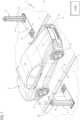
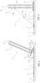
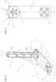
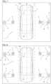
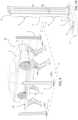
Figure 1 is a perspective view of a vehicle optical scanning system according to the invention,Figures 2 and 3 show an optical image reader apparatus present in the vehicle optical scanning system shown inFigure 1 in two different operating conditions,Figure 4 is a perspective view, on a larger scale, of the optical image reader apparatus shown inFigures 1-3 , wherein broken lines indicate the inner parts,Figure 5 is a plan view, on a larger scale, of the optical image reader apparatus shown inFigures 1-4 ,Figure 6 shows the plate-shaped elements, on a larger scale, of the vehicle optical scanning system shown inFigure 1 ,Figure 7 is a view from the top of the vehicle optical scanning system shown inFigure 1 ,Figure 8 is a view from the top of the vehicle optical scanning system according to a variant,Figure 9 is a perspective view of the vehicle attitude control system according to a further variant,Figure 10 is a perspective view of the optical image reader apparatus shown inFigure 9 .- With reference to
Figures 1 to 7 ,number 1 indicates, as a whole, an optical scanning system for avehicle 2 for measuring and/or controlling thevehicle 2 and/or parts/components of thevehicle 2. - In the example shown in
Figures 1 and7 , thevehicle 2 is arranged in a control station, which comprises a plane, on which, in use, thewheels 3 of thevehicle 2 rest. The plane can correspond, for example, to the support surface, for instance a horizontal one. The support surface can correspond to a floor/ground present in the vehicle control station, for example inside a vehicle service department (which is not shown herein). Obviously, the plane can comprise any plane on which thewheels 3 of thevehicle 2 rest. - The
vehicle 2 can be a motor vehicle with an engine, in particular a car, and, in the example shown inFigures 1 ,6 and7 , it centrally has a longitudinal reference axis A and is provided with fourwheels 3 coupled, in pairs, to two corresponding axles, namely a front axle V1 and a rear axle V2, of thevehicle 2, which are transverse to the axis A (namely, orthogonal thereto in the accompanying Figures) and are at a given axle base distance from one another (measured along the axis A). - It is understood that in the description below, the
term wheel 3 indicates a common wheel of a car comprising at least a rim and a tyre. Furthermore it is understood that the invention is not limited to a car, but can be applied to any type of motor vehicle provided with any number of wheels and axles Vi (wherein i is variable =>2), for example a truck or a lorry or a bus, having two or more axles and four ormore wheels 3. - The
optical scanning system 1 is designed to determine a series of geometric parameters characterising thevehicle 2 and/or parts/components thereof. - According to a preferred embodiment of the invention, the geometric parameters of the parts/components of the vehicle can, for example, relate to: the
wheels 3 and/or the axles V1, V2 and/or the steering (which is not shown herein). The geometric parameters of thewheels 3 can comprise, for example: the angle or plane of attack of the wheel, the camber angle of the wheel, the toe angle or plane of the wheel. The angles or planes can preferably be determined relative to at least one predetermined three-dimensional reference system SR. The geometric parameters characterising thewheels 3 used in theoptical scanning system 1 for the control, for example, of the wheel attitude of thevehicle 2 are known and, therefore, will not be discussed any further. - It is understood that the
optical scanning system 1 is not limited to the determination of the above-mentioned geometric parameters for the control of the wheel attitude of thevehicle 2, but, in addition and/or alternatively, it can involve the determination of other pieces of information concerning thevehicle 2. These pieces of information can comprise, for instance, the position of thevehicle 2 within the vehicle control station P relative to the predetermined three-dimensional reference system SR. - According to this embodiment, the
optical scanning system 1 can be designed to determine the position of thevehicle 2 relative to the predetermined reference system SR based on the images of the axles V1 and/or V2 and/or of thewheels 3. According to this embodiment, theoptical scanning system 1 can be configured to communicate (for example, through wireless communication) data/signals indicative of the position of thevehicle 2 relative to a predetermined reference system SR to one or more vehicle analysis/diagnosis systems (which are not shown herein). Conveniently, a vehicle analysis/diagnosis systems can comprise a vehicle ADAS sensor control and/or calibration system (not shown), which is designed to control and/or calibrate advanced driver-assistance systems (ADAS) present in thevehicle 2. This control and/or calibration system is placed in the control station P, preferably in front of thevehicle 2, The vehicle ADAS sensor control and/or calibration system can receive the data/signals indicative of the position of the vehicle and determine its distance from thevehicle 2 based on its own position relative to the predetermined reference system SR of theoptical scanning system 1 and on the received position of thevehicle 2. - According to a preferred embodiment shown in
Figures 1-7 , theoptical scanning system 1 comprises opticalimage reader apparatuses 4. In the example shown inFigures 1 and7 , theoptical scanning system 1 comprises two opticalimage reader apparatuses 4, which are arranged so as to be opposite one another on opposite sides of thevehicle 2, on the periphery thereof. In the example shown herein, the two opticalimage reader apparatuses 4 are arranged on a surface P. In the description below, without because of this loosing in generality, but for the purpose of increasing the clarity of the invention, an example will be taken into account, in which the support surface P of the two opticalimage reader apparatuses 4 is approximately coplanar to the support surface PV of thevehicle 2. However, according to the invention, the surface P could not be coplanar and/or parallel to the support surface PV of thevehicle 2. - The optical
image reader apparatuses 4 are arranged so as to face two corresponding sides (lateral flanks) of thevehicle 2, which are parallel to and opposite relative to the axis A. In the example shown herein, the opticalimage reader apparatuses 4 are arranged so as to face the two sides of thevehicle 2 approximately in the area of the middle axis of thevehicle 2. However, the opticalimage reader apparatuses 4 can be arranged so as to face thewheels 3 of thevehicle 2. - The optical
image reader apparatuses 4 are provided with respective optical image capturing devices 9 (described in detail below), which are configured to provide respective data/signals encoding one or more images entirely - or at least partially - representing the opposite sides of thevehicle 2 relative to the axis A. - The
optical scanning system 1 further comprises a control andprocessing system 5, which is designed to process the data/signals provided by the opticalimage capturing devices 9 in order to determine/construct 3D (three-dimensional) images of thevehicle 2 and/or of parts thereof, by means of artificial vision algorithms, based on said data/signals. The aforesaid artificial vision algorithms are known and, as a consequence, will not be described any further. Furthermore, the opticalimage reader apparatuses 4 each comprise a target 6 (or calibration target), which lies on the plane K (Figures 2 and 3 ) and is arranged immediately adjacent to the opticalimage capturing device 9 of the relative opticalimage reader apparatus 4. Thetarget 6 is arranged on the reference plane K at a predetermined distance D1 from the relative opticalimage capturing device 9. Thetarget 6 is arranged on the reference plane K so that it can be framed/visualized by the relative opticalimage capturing device 9. - In the example shown in
Figures 1 to 7 , the reference plane K is approximately horizontal. Thetarget 6 can conveniently be arranged between the optical image capturing device and the side of thevehicle 2 facing the opticalimage capturing device 9. It is understood that according to the invention, thetarget 6 can be placed in any superficial position of the reference plane K that surrounds theimage capturing device 9 and is immediately adjacent thereto so that it can be framed/visualized. - The electronic processing and
control system 5 is designed to calibrate the opticalimage reader apparatuses 4 based on the images of therespective targets 6. - The Applicant found out that, by placing the
target 6 directly close to the opticalimage capturing device 9 at a predetermined fixed distance D1 and by processing the image of thetarget 6 itself, a calibration of the opticalimage reader apparatus 4 comprising thetarget 6 and the opticalimage capturing device 9 can be carried out, even when thevehicle 2 is interposed/standing between the opticalimage reader apparatuses 4. As described below, by determining the relative position between thetarget 6 and theoptical device 9 at predetermined instants, it is possible to identify and, hence, make up/compensate for possible movements of thereader apparatus 4 relative to its initial position (zero position) calculated relative to thesame target 6. - With reference to
Figures 1-7 , each opticalimage reader apparatus 4 further comprises a plate-shapedelement 7, which has a longitudinal axis C. The plate-shapedelement 7 is arranged on the surface P and has, on its upper surface, thetarget 6. It is understood that the plate-shapedelement 7 is arranged on a superficial portion of the surface on the periphery of thevehicle 2. - The optical
image reader apparatus 4 further comprises asupport column 8, which extends along a longitudinal axis B and is coupled to the plate-shapedelement 7 in a position immediately adjacent to thetarget 6. Thecolumn 8 can be coupled to the plate-shapedelement 7 so that its longitudinal axis B is approximately orthogonal to the plate-shapedelement 7 and to its axis C. Thecolumn 8 supports at least one opticalimage capturing device 9. The opticalimage capturing device 9 is arranged in thecolumn 8 so as to frame and capture the image of thetarget 6 present on the underlying plate-shapedelement 7. According to a preferred embodiment shown inFigures 1-7 , the upper surface of the plate-shapedelement 7 is approximately flat and forms the plane K on which thetarget 6 is arranged. The plate-shapedelement 7 further has a lower surface opposite the upper surface, which can be approximately flat. In the example shown inFigures 1-7 , said lower surface rests on the surface P and is firmly fixed/anchored to the latter. - According to a preferred embodiment shown in
Figures 1-7 , the plate-shapedelement 7 can comprise, for example, a flat plate or bracket made of a rigid material. Said rigid material can contain, for example, metal materials and/or polymer materials (plastic) or similar materials. In the example shown herein, the plate-shapedelement 7 has an approximately rectangular shape and has, at a first axial end, thetarget 6. Thetarget 6 is approximately planar, can comprise a two-dimensional (quadrangular) image representing a predetermined (calibration) pattern and is firmly fixed on the upper surface of the plate-shapedelement 7 at its first axial end opposite the portion to which thesupport column 8 is coupled. In the example shown herein, the pattern comprises a geometry containing predetermined graphic elements (squares) in a (black and white) chessboard-like arrangement. - According to a preferred embodiment shown in
Figures 1-7 , thesupport column 8 can comprise a tubular section bar. Preferably, thetubular section bar 8 can have a polygonal section crosswise to the axis B. In the example shown herein, thesupport column 8 has a rectangular or square section and has four vertical rectangular faces parallel to the axis B. The upper end of thesupport column 8 preferably is closed and shaped like a grip. - The
support column 8 can have the lower end closed by acoupling plate 11. Thecoupling plate 11 can conveniently be arranged orthogonal to the axis B. Thecoupling plate 11 can have a flat polygonal shape (namely, a square or rectangular or hexagonal shape) and has, on at least one side, one or more slidingwheels 12. Thewheels 12 can preferably be cylindrical and be arranged on one side of thecoupling plate 11. In use, thecoupling plate 11 can be placed approximately on the second end of the plate-shapedelement 7 opposite the first end accommodating thetarget 6 at a predetermined distance from the latter, so that the opticalimage capturing device 9 mounted in thecolumn 8 is arranged at the predetermined distance D1 from thetarget 6. The technical effect of thewheels 12 is that of facilitating the manual displacement of the opticalimage reader apparatus 4. - With reference to
Figures 2-3 , the opticalimage reader apparatus 4 can further conveniently comprise aconnection device 13, which is structured to fix/anchor, in a stable yet easily separable/removable manner, thesupport column 8 to the plate-shapedelement 7. - According to a convenient embodiment (
Figures 2 and 3 ), theconnection element 13 can comprise amagnetic coupling system 14 to magnetically couple/anchor thecolumn 8 to the plate-shapedelement 7. Themagnetic coupling system 14 can comprise, for example, one or moremagnetic elements 14a with opposite magnetic poles, at least one of them being arranged on the second end of the plate-shapedelement 7. Anothermagnetic element 14a can be arranged, for example, on thesupport column 8, preferably in thecoupling plate 11. The Applicant found out that the technical effect of themagnetic coupling system 14 is that of making the coupling of thesupport column 8 to the plate-shapedelement 7 quick and simple. Theconnection device 13 can comprise, instead of or in addition to themagnetic coupling system 14,mechanical coupling members 17, for example threaded joining elements (screws and/or nuts) or any similar mechanism, to anchor/fix thecoupling plate 11 on the plate-shapedelement 7. - With reference to
Figures 2 and6 , the opticalimage reader apparatus 4 can further comprise a self-centringmechanism 15 to centre the coupling of thesupport column 8 on the second end of the plate-shapedelement 7. The self-centringmechanism 15 can comprise one or more projections orprotuberances 16, which are arranged on the upper surface of the second end of the plate-shapedelement 7 in predetermined points. The self-centringmechanism 15 can comprise a series of seats (not shown herein), which are obtained on the lower surface of thecoupling plate 11 and have a position and a shape that are complementary to the position and the shape of theprojections 16 in order to accommodate them when thecoupling plate 11 rests on the second end of the plate-shapedelement 7. - The
projections 16 of the self-centringmechanism 15 can conveniently be sized and structured so that thecoupling plate 11, when in it is arranged on the predetermined portion of the plate-shapedelement 7, remains in a horizontal position, slightly lifted from the upper surface of the underlying plate-shapedelement 7 at a height that is such as to also keep thewheels 12 lifted and not in contact with the surface P. - With reference to
Figures 3 and4 , the opticalimage capturing device 9 comprises at least onecamera 9a. In the example shown herein, the opticalimage capturing device 9 further comprises acamera 9b, which is arranged at a predetermined distance from thecamera 9a. Thecameras control system 5 so as to implement a binocular stereoscopic vision method. The operation of the binocular stereoscopic vision method by means of two cameras in order to construct a 3D image is known and will not be described any further. - According to a preferred embodiment shown in
Figure 1-7 , thecamera 9a and thecamera 9b are firmly arranged in thesupport column 8 so that the relative optical assemblies (lenses) face and are oriented on a common face/side of thesupport column 8 so as to frame a side of thevehicle 2. - Preferably, the
cameras vehicle 2 through through openings made in the face/side of thecolumn 8. Thecameras column 8 so as to be axially spaced apart from one another along the longitudinal axis B at said predetermined distance. Preferably, the opticalimage capturing device 9 can further comprise at least onelight source 9c, which is designed to emit a light beam to irradiate thetarget 6. - According to the preferred embodiment shown in
Figures 3 and4 , thecamera 9a is arranged in thesupport column 8 in a lower intermediate position, above thecoupling plate 11. Thecamera 9b is arranged in thesupport column 8 in an upper intermediate position, immediately under the upper end of thecolumn 8 itself. Preferably, thecamera 9b is configured so as to frame both the side of thevehicle 2 and thetarget 6 present in the underlying plate-shapedelement 7. Preferably, thecamera 9a is configured to frame the side of thevehicle 2. - It is understood that the invention is not limited to an optical vision architecture that entails the use of
cameras support column 8. - Furthermore, according to a different embodiment (which is not shown herein) alternative to the preferred embodiment described above, there can be an optical vision architecture with time-of-flight 3D image scanning and construction, which entail the use of a camera and of an IR (InfraRed) and/or (pulsed) laser emitter or projector or the like. According to a preferred embodiment shown in
Figure 1 , the processing andcontrol system 5 can comprise one ormore processing units 5a, which can conveniently be arranged inside thesupport columns 8. Theprocessing units 5a can be configured to communicate with one another through a wireless communication system (which is not shown herein) in order to exchange the data/signals concerning the captured images. Theprocessing system 5 can further comprise, alternatively or in addition to the processing units 5s, acentral processing unit 500. Theprocessing units 5a can comprise microprocessors or similar electronic processing circuits, whereas the central theprocessing unit 500 can comprise a desktop computer or a laptop or any other similar processing device. For example, the processing andcontrol system 5 can construct, by means of thecameras wheel 3, in which each point (pixel) of the image is a function of the distance between the detail of the wheel taken into account and thecamera 9b. - With reference of
Figure 6 , the optical scanning method implemented by thesystem 1 entails, at first, a fixing operation to fix the plate-shapedelements 7 on the surface P in opposite positions. The plate-shapedelements 7 are fixed in predetermined points of the surface P on opposite sides of thevehicle 2. Preferably, the plate-shapedelements 7 are fixed on the surface P in a rigid (firm) manner, for example by means of known fixing members (screws or the like, which are not shown herein), and can have the relative axes C approximately aligned with (coaxial to) one another. With reference toFigures 1 and7 , the method further comprises the step of coupling thecolumns 8 on the plate-shapedelements 7 so as to form the opticalimage reader apparatuses 4. When thecolumn 8 is coupled to the relative plate-shapedelement 7, the axis B is approximately vertical, its optical image capturing device is arranged at the predetermine distance D1 from thetarget 6 and frames thevehicle 2. It is understood that according to a different embodiment (which is not shown herein), thecolumns 8 can be firmly fixed on the plate-shapedelements 7 so as to form one single body. In this case, the fixing of the plate-shapedelements 7 on the surface also determines, at the same time, the positioning of therelative columns 8. - The method comprises a method for adjusting the optical
image reader apparatuses 4, a method for measuring and/or controlling thevehicle 2 and/or parts/components of thevehicle 2 and a method for the calibration of the opticalimage reader apparatuses 4. - The adjustment method entails the step of determining the position of each optical
image reader apparatus 4 relative to the other opticalimage reader apparatuses 4 in the predetermined reference system SR. InFigure 1 , in order to increase the understanding of the invention, the reference system SR is arranged in the area of thecamera 9b of an opticalimage reader apparatus 4. - The determination of the space position of each optical image reader apparatus 4 (coordinates) relative to the reference system SR can be carried out, for example, by vertically placing an adjustment panel (which is not shown) on the surface P between the optical
image reader apparatuses 4, approximately in the middle of the distance between the twoopposite columns 8. The adjustment panel (which is not shown) can comprise, on the two opposite faces, two adjustment targets, each facing anapparatus 4. The opticalimage capturing devices 9 can capture the image of the two relative targets present on the adjustment panel. - The
processing system 5 determines the distances of the opticalimage reader apparatuses 4 from the adjustment panel based on the processed images. By means of image processing and triangulation algorithms, which use, for example, suitable transformation matrices, theprocessing system 5 can determine the positions and the angles (of the optical axes) of each opticalimage reader apparatus 4 relative to the reference system SR. Obviously, in this step, the processing andcontrol system 5 can store the intrinsic parameters of the twocameras optical device 9, such as for example focal length, dimensions of a pixel, distortion parameters and their "exposure", namely position and angular orientation, relative to one another. According to the invention, during the adjustment step, the opticalimage capturing device 9 of each opticalimage reader apparatus 4 further captures the image of thetarget 6 present on the underlying plate-shapedelement 7. - The
processing system 5 processes the image of thetarget 6 and determines, by means of an image processing algorithm, both the distance D1 of the opticalimage capturing device 9 relative to thetarget 6 and the angular orientation of the opticalimage capturing device 9 relative to thetarget 6. The angular orientation of the opticalimage capturing device 9 can be indicative, for example, of the angular orientation of the optical axis of thecamera 9b relative to thetarget 6. - The
processing system 5 determines, based on the distance D1 of the opticalimage capturing device 9 and on the angular orientation thereof, an initial position (zero position) and an initial angular orientation (zero orientation) of theapparatus 4 relative to the relative target 6 (self-zero condition) in the reference system SR. It should be pointed out that eachtarget 6 is a fixed reference useful to determine, following the adjustment, the change in the position and/or the change in the angular orientation of therelative apparatus 4 with a high degree of precision. - The
processing system 5 can store the geometric data obtained during the adjustment. The data can comprise: the space positions and the angular orientations of the optical image reader apparatuses 4 (relative to one another) in the three-dimensional reference system SR, the space positions and the angular orientations of each opticalimage reader apparatus 4 relative to therespective target 6 in the three-dimensional reference system SR. - Following the initial adjustment, the
scanning system 1 is capable of implementing the method for measuring and/or controlling thevehicle 2 and/or the parts/components of thevehicle 2. According to said method, theprocessing system 5 processes the data/signals provided by theimage reader apparatuses 4 in order to determine the three-dimensional images of the sides of thevehicle 2. - According to a preferred embodiment of the method, the
processing system 5 processes the data/signals received from theimage reader apparatuses 4 through image processing algorithms in order to determine the geometric parameters characterising thewheels 3 of thevehicle 2. According to the method, for example, the processing andcontrol system 5 determines the position and the angle of thewheels 3 relative to the predetermined reference system SR. According to the method, for example, the processing andcontrol system 5 determines the position and the angle of the axles V1, V2 of thevehicle 2 relative to the predetermined reference system SR. According to the method, furthermore, the processing andcontrol system 5 determines the position of thevehicle 2 based on the position of thewheels 3 and/or of the axles V1, V2 relative to the predetermined reference system SR. - In case the space taken up by the
apparatuses 4 in the control station needs to be freed, thecolumns 8 can conveniently be uncoupled from the plate-shaped elements 7 (Figure 6 ). In this condition, the plate-shapedelements 7 remain in the relative predetermined fixed position, but their planar/flat and thin shape has irrelevant dimensions. - When the method for measuring and/or controlling a
vehicle 2 and/or the parts/components of thevehicle 2 needs to be implemented again, thecolumns 8 are fitted again onto the relative plate-shapedelements 7 so as to form the opticalimage reader apparatuses 4 of thesystem 1. - Conveniently, the method entails the implementation of the method for calibrating the optical
image reader apparatuses 4 relative to therelative targets 6. It should be pointed out that the method does not require again the implementation of the adjustment method described above, since the position of the plate-shapedelements 7 relative to the reference system SR remains unchanged. - According to the calibration method, the two optical
image reader apparatuses 4 capture the image of the twotargets 6 present on the corresponding plate-shapedelements 7. According to the calibration method, for eachreader apparatus 4, theprocessing system 5 processes the image of therelative target 6 captured by thecamera 9b and determines the actual distance D1 of the corresponding opticalimage capturing device 9 relative to thecorresponding target 6 and the actual angular orientation of the opticalimage capturing device 9 relative to thetarget 6. - For example, according to a possible processing, the image provided by the
camera 9b can be analysed/processed so as to determine the two-dimensional 2D position (in pixels) of some specific points of thetarget 6. Furthermore, the position of these points relative to three-dimensional reference system SR is assumed to be known. Therefore, for each point of thetarget 6 taken into account, its position both in the two-dimensional image plane and relative to the reference system SR is known. The 2D-3D (two-dimensional - three-dimensional) correspondences provide an over-determined equation system, which is solved by the processing andcontrol system 5 in order to estimate the exposure (position and angular orientation) of thecamera 9b relative to therelative target 6. - According to the calibration method, the processing and
control system 5 determines, for eachoptical reader apparatus 4, the distance variation, namely the difference between the distance D1 measured during the calibration method and the distance D1 measured and stored during the adjustment method (zero position). According to the calibration method, the processing andcontrol system 5 determines, for eachoptical reader apparatus 4, the angular variation, namely the difference between the angular orientation of the opticalimage capturing device 9 determined during the calibration method and the angular orientation of the opticalimage capturing device 9 determined during the adjustment method (zero orientation). - According to the calibration method, the
processing system 5 stores, for eachoptical reader apparatus 4, the determined distance variation and the determined angular orientation variation. - The calibration method entails automatically calibrating each optical reader apparatus 4 (distance and angular orientation) based on the detected distance and angular orientation variations.
- During the following implementation of the method for measuring and/or controlling the
vehicle 2 and/or the parts/components of thevehicle 2, theprocessing system 1 can, for example, introduce offsets in the images and/or in the measures and/or in the geometric parameters based on the distance and angular orientation differences determined for the optical image reader. - For example, the offsets can be stored in correction/compensation matrices containing numerical values indicative of the offsets to be applied to the distances and/or to the angles to be taken into account during the construction of the three-dimensional image of the
vehicle 2. - The system described above is advantageous in that it is capable of carrying out the calibration with a high precision and frequency, even when a vehicle is standing in the control station.
- Furthermore, thanks to the configuration of the plate-shaped elements, the columns can be removed form the control station so as to clear the space taken up by them. With every following installation of the support columns on the plate-shaped elements, the system is capable of ensuring a high precision thanks to the implementation of the calibration method, with no need to carry out a new adjustment using the panel with the adjustment target. It should be pointed out that, on the one hand, the position of the column and, hence, of the image reader apparatus relative to the reference system SR remains stable and, on the other hand, possible changes in the position and/or orientation of the apparatus relative to the adjustment condition are detected and made up for with utmost precision thanks to the processing of the image of the reference target of the apparatus.
- Finally, it is clear that the system and the method described above can be subject to changes and variations, without for this reason going beyond the scope of protection of the present invention defined in the appended claims.
- The embodiment schematically shown in
Figure 8 relates to anoptical scanning system 40, which is similar to theoptical scanning system 1 described above and whose components will be identified, when possible, with the same reference numbers as the ones indicating theoptical scanning system 1 described above with reference toFigures 1-7 . - The
optical scanning system 40 differs from theoptical scanning system 1 in that it is provided with fourimage reader apparatuses 4 instead of twoimage reader apparatuses 4. - With reference to
Figure 8 , twoimage reader apparatuses 4 are arranged on opposite sides of the axis A of thevehicle 2 in positions approximately facing therespective wheels 3 of the front axle V1 of the vehicle. The other twoimage reader apparatuses 4 are arranged on opposite sides of the axis A in positions approximately facing therespective wheels 3 of the rear axle V2 of thevehicle 2. - The operation of and the method implemented by the
optical scanning system 40, namely, in particular, the method for adjusting and calibrating eachapparatus 4 of theoptical scanning system 40, correspond to the method for adjusting and calibrating eachapparatus 4 of theoptical scanning system 1. - The embodiment shown in
Figures 9 and 10 relates to anoptical scanning system 50, which is similar to theoptical scanning system 1 described above and whose components will be identified, when possible, with the same reference numbers as the ones indicating theoptical scanning system 1 described above with reference toFigures 1-7 . - The
optical scanning system 50 differs from theoptical scanning system 1 in that it comprises four opticalimage reader apparatuses 4 arranged on the surface P similarly to the opticalimage readers apparatuses 4 of theoptical scanning system 40 and in that each opticalimage reader apparatus 4 comprises two opticalimage capturing devices 9 axially spaced apart along the axis B, instead of one single optical image capturing device 9 (Figure 10 ). In each opticalimage reader apparatus 4, a first opticalimage capturing device 9 is arranged in the lower portion of thecolumn 8 and a second opticalimage capturing device 9 is arranged in the upper portion of thecolumn 8 above the other opticalimage capturing device 9. - The
optical scanning system 50 further differs from theoptical scanning system 1 in that the control station comprises a movable surface PK, which supports thevehicle 2. The surface PK is designed to be moved, on command, between a rest position (first position, not shown herein), in which it is approximately coplanar to the surface P, and a work position (second position) (shown infigure 9 ), in which the surface PK is lifted relative to the rest position (and to the surface P) at a predetermined height H. The movable surface PK can correspond, for example, to a movable platform of a lift 52 forvehicles 2. The lift 52 shown herein is known and, therefore, will not be described any further. - The first optical
image capturing device 9 can be arranged in thesupport column 8 of theapparatus 4 so that itsupper camera 9b frames thetarget 6 and the side of thevehicle 2 when the surface PK is in the rest position. - The second optical
image capturing device 9 is arranged in thesupport column 8 so that itsupper camera 9b and itslower camera 9a frame the side of thevehicle 2 when the surface PK is in the operating work position. Hence, the electronic processing andcontrol system 5 selectively operates the first and the second opticalimage capturing device 9 based on the position of the work surface PK relative to the surface P. Preferably, the height H1 of thecolumns 8 is greater than the height H of the work surface PK in the work position.
Claims (15)
- An optical scanning system (1) for measuring and/or controlling a vehicle (2) and/or parts of a vehicle (2), wherein the vehicle (2) is arranged on a control station, the optical scanning system (1) comprises:at least two optical reader apparatuses (4) which are arranged on a plane (P) of said control station, on opposite sides of the longitudinal axis (A) of said vehicle (2), in order to be facing to the opposite lateral sides of the vehicle (2),the two optical reader apparatuses (4) are provided with respective optical image capturing devices (9) configured to provide respective data encoding one or more images at least partially containing said opposite sides of the vehicle (2),an electronic processing and control system (5) which is designed to process said data in order to determine one or more three-dimensional images relative to said vehicle (2) and/or to parts of the vehicle (2),said optical reader apparatuses (4) each comprise:a calibration target (6) which is positioned immediately adjacent to the optical image capturing device (9) of the relative optical reader apparatus (4) at a pre-established distance (D1) from the same,said optical image capturing device (9) is designed to capture one or more images of said adjacent target (6) in order to provide respective data encoding the image of the target (6) itself,said electronic processing and control system (5) is designed to calibrate said optical reader apparatuses (4) based on the images of the respective targets (6), said optical scanning system (1) ischaracterised in thatsaid optical image capturing reader apparatus (4) comprises:a plate-shaped element which is fixed firmly on said plane (P) in a position approximately adjacent to a side of the vehicle (2), and has an upper surface on which said target (6) is placed,a column (8) which is coupled to the plate-shaped element (7) so that its longitudinal axis (B) is approximately orthogonal to said plate-shaped element (7) and so that the relative optical image capturing device (9) is arranged at said pre-established distance (D1) from said target (6),said optical image capturing device (9) is firmly coupled in said column (8) and is configured so as to capture the image of the target (6) present on the underlying plate-shaped element (7).
- The optical scanning system according to claim 1, comprising a connection device (13) structured to fix, in a stable yet easily separable manner, said column (8) to said plate-shaped element (7).
- The optical scanning system according to claims 1 or 2, wherein said connection device (13) comprises a magnetic coupling system (14) for magnetically fixing said column (8) to said plate-shaped element (7).
- The optical scanning system according to any of foregoing claims, wherein said optical image capturing device (9) comprises at least a first camera (9a).
- The optical scanning system according to claim 4, wherein said optical image capturing device (9) comprises at least a second camera (9b) which cooperates with said first camera (9a) in order to define with the same a binocular stereo vision system.
- The optical scanning system according to claim 5, wherein said first (9a) and second (9b) cameras are arranged in the relative column (8) along a relative longitudinal axis (B) mutually spaced from one another.
- The optical scanning system according to any of foregoing claims, wherein said optical image capturing device (9) of said optical reader apparatus (4) comprises at least a light source (9c) designed to emit a light beam to selectively irradiate said target (6) present on the upper surface of said plate-shaped element (7) of the optical reader apparatus (4) itself.
- The system according to claim 6, wherein said control station comprises a movable support surface of said vehicle (2) which is designed to be moved between a first and a second operating position having respective heights with respect to the surface (P) one being greater than the other; said optical reader apparatuses (4) each comprise two optical image capturing devices (9) which are arranged in the relative column (8) axially spaced one from the other, at respective heights which depend upon the heights of the support surface in the first and second operating positions,
said electronic processing and control system (5) is designed to selectively actuate the optical image capturing devices (9) in the column (8) based on the positioning of said support surface in the first and second operating positions. - The optical scanning system according to any of foregoing claims, wherein said electronic processing and control system (5) is configured to process said data in order to construct one or more three-dimensional images relative to parts of the vehicle (2) corresponding to the wheels (3) of the vehicle (2), and process said images in order to determine geometric parameters that characterise said wheels (3) with respect to a pre-established reference system (SR).
- The optical scanning system according to any of foregoing claims , wherein said electronic processing and control system (5) is configured to process said data in order to construct one or more three-dimensional images relative to parts of the vehicle (2) corresponding to at least an axle of the vehicle (2), and process said images in order to determine the position and/or the orientation of said vehicle in said control station with respect to said pre-established reference system (SR).
- The optical scanning system according to claim 10, wherein said electronic processing and control system (5) is configured to communicate to at least an advanced driver-assistance system, ADAS, calibration system, data indicative of the position and/or orientation of said vehicle (2) in said control station with respect to the pre-established reference system (SR).
- The optical scanning system according to any foregoing claims, comprising four image reader apparatuses (4), which are arranged in positions facing respective wheels (3) of said vehicle.
- An optical scanning method designed to measure and/or control a vehicle (2) and/or parts of a vehicle (2), wherein the vehicle (2) is arranged in a control station,the method comprises the steps of:positioning at least two optical reader apparatuses (4) on a surface (P) of said control station, on opposite sides of the longitudinal axis (A) of said vehicle (2), in order to be facing opposite sides of the vehicle (2), wherein the two optical reader apparatuses (4) are provided with respective optical image capturing devices (9) configured to provide respective data encoding one or more images at least partially containing said opposite sides of the vehicle (2), processing said data in order to determine one or more three-dimensional images relative to said vehicle (2) and/or to parts of the vehicle (2),arranging a calibration target (6) on said surface (P) in a position immediately adjacent to the optical image capturing device (9) of the relative optical reader apparatus (4) at a pre-established distance (D1) from the same,acquiring, via optical image capturing device (9), one or more images of said adjacent target (6) thus providing respective data encoding the image of the target (6) itself,calibrating said optical reader apparatuses (4) based on the images of the respective target (6),said method beingcharacterised in that:said optical image capturing reader apparatus comprises (4)a plate-shaped element (7), which has an upper surface, on which said target (6) is arranged,and a column (8), in which said optical image capturing device (9) is arranged,the method comprises the steps of:firmly fixing said plate-shaped element (7) on said surface (P) in a position approximately adjacent to a side of the vehicle (2)coupling said column (8) to the plate-shaped element (7) so that its longitudinal axis (B) is approximately orthogonal to said plate-shaped element (7) and so that the relative optical image capturing device (9) is arranged at said pre-established distance (D1) from said target (6),acquiring the image of the target (6) present on the underlying plate-shaped element (7) by means of said optical image capturing device (9) present in said column (8).
- The method according to claim 13, comprising the step of fixing, in a stable yet easily separable manner, said column (8) to said plate-shaped element (7) by means of a connection device (13).
- The method according to claims 13 or 14, comprising the step of magnetically fixing said column (8) to said plate-shaped element (7) by means of a magnetic coupling system (14).
Applications Claiming Priority (1)
| Application Number | Priority Date | Filing Date | Title |
|---|---|---|---|
| IT202000030578 | 2020-12-11 |
Publications (2)
| Publication Number | Publication Date |
|---|---|
| EP4012328A1 EP4012328A1 (en) | 2022-06-15 |
| EP4012328B1true EP4012328B1 (en) | 2023-11-01 |
Family
ID=74875008
Family Applications (1)
| Application Number | Title | Priority Date | Filing Date |
|---|---|---|---|
| EP21213897.8AActiveEP4012328B1 (en) | 2020-12-11 | 2021-12-10 | System and method of optical scanning of a vehicle for measuring and/or controlling the vehicle and/or parts thereof |
Country Status (4)
| Country | Link |
|---|---|
| US (1) | US11928841B2 (en) |
| EP (1) | EP4012328B1 (en) |
| CN (1) | CN114623785A (en) |
| ES (1) | ES2969593T3 (en) |
Cited By (2)
| Publication number | Priority date | Publication date | Assignee | Title |
|---|---|---|---|---|
| EP4421445A1 (en) | 2023-02-23 | 2024-08-28 | Vehicle Service Group Italy S.R.L. | Calibration apparatus and method of verifying the positioning of a calibration device, in particular for calibrating one or more adas sensors |
| EP4563934A1 (en)* | 2023-11-29 | 2025-06-04 | Shenzhen Smartsafe Tech Co., Ltd. | Four-wheel alignment measuring device and four-wheel alignment apparatus |
Families Citing this family (3)
| Publication number | Priority date | Publication date | Assignee | Title |
|---|---|---|---|---|
| US11279327B1 (en)* | 2020-09-04 | 2022-03-22 | Richard L. Jackson, JR. | Vehicle sensor calibration target alignment system |
| CN116698447B (en)* | 2023-08-04 | 2023-10-20 | 安徽中科星驰自动驾驶技术有限公司 | Calibration device of double-target type automatic driving auxiliary system |
| CN118247282B (en)* | 2024-05-29 | 2024-07-26 | 江苏瑞问科技有限公司 | Target intelligent monitoring system and method applying artificial intelligent technology |
Family Cites Families (11)
| Publication number | Priority date | Publication date | Assignee | Title |
|---|---|---|---|---|
| US6498959B1 (en)* | 2000-01-19 | 2002-12-24 | Hunter Engineering Company | Apparatus and method for controlling a mechanism for positioning video cameras for use in measuring vehicle wheel alignment |
| ITFI20060196A1 (en)* | 2006-08-04 | 2008-02-05 | Fasep 2000 S R L | METHOD AND DEVICE FOR MEASURING WITHOUT CONTACT WITH WHEEL ALIGNMENT OF MOTOR VEHICLES |
| US8106924B2 (en)* | 2008-07-31 | 2012-01-31 | Stmicroelectronics S.R.L. | Method and system for video rendering, computer program product therefor |
| DE102008042018A1 (en)* | 2008-09-12 | 2010-03-18 | Robert Bosch Gmbh | Method for adjusting or calibrating a vehicle surroundings sensor and vehicle surroundings sensor adjustment or calibration arrangement |
| ITMI20111695A1 (en)* | 2011-09-21 | 2013-03-22 | Cemb S P A | DEVICE AND MEASUREMENT PROCEDURE FOR DIMENSIONS AND CORNERS OF WHEELS, STEERING AND CHASSIS OF VEHICLES IN GENERAL. |
| DE102014219109A1 (en)* | 2014-09-23 | 2016-03-24 | Robert Bosch Gmbh | Reference system and transducers for use in vehicle surveying |
| US10240916B1 (en)* | 2016-01-05 | 2019-03-26 | Hunter Engineering Company | Method and apparatus for calibrating an inspection system for moving vehicles |
| KR102395276B1 (en)* | 2016-09-13 | 2022-05-09 | 현대자동차주식회사 | Apparatus for inspecting driver assistance system of vehicle and method for controlling the same |
| CN109791045B (en)* | 2016-10-04 | 2021-01-19 | 美国亨特工程公司 | Vehicle wheel alignment measurement system camera and ADAS calibration support structure |
| DE102017203426A1 (en) | 2017-03-02 | 2018-09-06 | Robert Bosch Gmbh | Calibration tray, measuring device and method for calibrating driver assistance systems |
| IT202000004834A1 (en)* | 2020-03-06 | 2021-09-06 | Nexion Spa | METHOD OF ALIGNING A SERVICE SYSTEM WITH A VEHICLE RELATIVE TO A VEHICLE |
- 2021
- 2021-12-10CNCN202111510953.9Apatent/CN114623785A/enactivePending
- 2021-12-10EPEP21213897.8Apatent/EP4012328B1/enactiveActive
- 2021-12-10USUS17/547,441patent/US11928841B2/enactiveActive
- 2021-12-10ESES21213897Tpatent/ES2969593T3/enactiveActive
Cited By (2)
| Publication number | Priority date | Publication date | Assignee | Title |
|---|---|---|---|---|
| EP4421445A1 (en) | 2023-02-23 | 2024-08-28 | Vehicle Service Group Italy S.R.L. | Calibration apparatus and method of verifying the positioning of a calibration device, in particular for calibrating one or more adas sensors |
| EP4563934A1 (en)* | 2023-11-29 | 2025-06-04 | Shenzhen Smartsafe Tech Co., Ltd. | Four-wheel alignment measuring device and four-wheel alignment apparatus |
Also Published As
| Publication number | Publication date |
|---|---|
| EP4012328A1 (en) | 2022-06-15 |
| ES2969593T3 (en) | 2024-05-21 |
| CN114623785A (en) | 2022-06-14 |
| US20220189067A1 (en) | 2022-06-16 |
| US11928841B2 (en) | 2024-03-12 |
Similar Documents
| Publication | Publication Date | Title |
|---|---|---|
| EP4012328B1 (en) | System and method of optical scanning of a vehicle for measuring and/or controlling the vehicle and/or parts thereof | |
| US20230213333A1 (en) | Wheel aligner with improved accuracy and no-stop positioning using a drive direction calculation | |
| US11993282B2 (en) | Apparatus and method for calibrating and aligning automotive sensors | |
| US10240916B1 (en) | Method and apparatus for calibrating an inspection system for moving vehicles | |
| EP3472555B1 (en) | Vehicle wheel alignment method and system | |
| EP2150772B1 (en) | Method for use with an optical aligner system for positioning a fixture relative to a vehicle | |
| KR101831672B1 (en) | Detection device, and corresponding system for determining the orientation of the wheels of a vehicle | |
| EP1882155B1 (en) | Wheel aligner measurement module attachment system | |
| US7121011B2 (en) | Camera technique for adaptive cruise control (ACC) sensor adjustment | |
| US20110085181A1 (en) | Measuring head for a chassis measuring system, chassis measuring system and method for determining the position parameters of measuring heads of a chassis measuring system | |
| US20210291376A1 (en) | System and method for three-dimensional calibration of a vision system | |
| EP1295086A1 (en) | Glint-resistant position determination system | |
| KR19980033400A (en) | Non-contact measuring method and device of camber and caster of vehicle wheel | |
| US20130141545A1 (en) | Method for calibrating a measurement system and device for carrying out the method | |
| CN111508027A (en) | Method and device for calibrating external parameters of camera | |
| CN118376166B (en) | Calibration method of measuring device, measuring method, device, medium and program product | |
| CN110709670B (en) | Method and device for measuring dimensions and characteristic angles of wheels, steering system and chassis of a vehicle | |
| KR20220058740A (en) | System and Method for calibration of robot based on a scanning | |
| CN115100289A (en) | Camera sensor installation state calibration method | |
| US11640680B2 (en) | Imaging system and a method of calibrating an image system | |
| EP4180763B1 (en) | Vehicle measuring apparatus and operating method thereof | |
| US20230386084A1 (en) | Apparatus for calibrating a three-dimensional position of a centre of an entrance pupil of a camera, calibration method therefor, and system for determining relative positions of centres of entrance pupils of at least two cameras mounted on a common supporting frame to each other, and determination method therefor | |
| CN210198312U (en) | Device for positioning ADAS calibration target plate position with camera installed on lifter | |
| EP4386314A1 (en) | A method for calibrating a set of laser profilometers | |
| US20230365148A1 (en) | Method for aligning a vehicle to an adas calibration target and an adas calibration system |
Legal Events
| Date | Code | Title | Description |
|---|---|---|---|
| PUAI | Public reference made under article 153(3) epc to a published international application that has entered the european phase | Free format text:ORIGINAL CODE: 0009012 | |
| STAA | Information on the status of an ep patent application or granted ep patent | Free format text:STATUS: THE APPLICATION HAS BEEN PUBLISHED | |
| AK | Designated contracting states | Kind code of ref document:A1 Designated state(s):AL AT BE BG CH CY CZ DE DK EE ES FI FR GB GR HR HU IE IS IT LI LT LU LV MC MK MT NL NO PL PT RO RS SE SI SK SM TR | |
| STAA | Information on the status of an ep patent application or granted ep patent | Free format text:STATUS: REQUEST FOR EXAMINATION WAS MADE | |
| 17P | Request for examination filed | Effective date:20221214 | |
| RBV | Designated contracting states (corrected) | Designated state(s):AL AT BE BG CH CY CZ DE DK EE ES FI FR GB GR HR HU IE IS IT LI LT LU LV MC MK MT NL NO PL PT RO RS SE SI SK SM TR | |
| GRAP | Despatch of communication of intention to grant a patent | Free format text:ORIGINAL CODE: EPIDOSNIGR1 | |
| STAA | Information on the status of an ep patent application or granted ep patent | Free format text:STATUS: GRANT OF PATENT IS INTENDED | |
| RIC1 | Information provided on ipc code assigned before grant | Ipc:G01B 11/275 20060101ALI20230421BHEP Ipc:G01B 11/24 20060101AFI20230421BHEP | |
| INTG | Intention to grant announced | Effective date:20230516 | |
| P01 | Opt-out of the competence of the unified patent court (upc) registered | Effective date:20230607 | |
| GRAS | Grant fee paid | Free format text:ORIGINAL CODE: EPIDOSNIGR3 | |
| GRAA | (expected) grant | Free format text:ORIGINAL CODE: 0009210 | |
| STAA | Information on the status of an ep patent application or granted ep patent | Free format text:STATUS: THE PATENT HAS BEEN GRANTED | |
| RAP1 | Party data changed (applicant data changed or rights of an application transferred) | Owner name:VEHICLE SERVICE GROUP ITALY S.R.L. Owner name:TEXA S.P.A. | |
| AK | Designated contracting states | Kind code of ref document:B1 Designated state(s):AL AT BE BG CH CY CZ DE DK EE ES FI FR GB GR HR HU IE IS IT LI LT LU LV MC MK MT NL NO PL PT RO RS SE SI SK SM TR | |
| REG | Reference to a national code | Ref country code:GB Ref legal event code:FG4D | |
| RIN1 | Information on inventor provided before grant (corrected) | Inventor name:MAMBRILLA, MASSIMO Inventor name:VIANELLO, BRUNO | |
| REG | Reference to a national code | Ref country code:CH Ref legal event code:EP | |
| REG | Reference to a national code | Ref country code:DE Ref legal event code:R096 Ref document number:602021006417 Country of ref document:DE | |
| REG | Reference to a national code | Ref country code:IE Ref legal event code:FG4D | |
| REG | Reference to a national code | Ref country code:LT Ref legal event code:MG9D | |
| REG | Reference to a national code | Ref country code:NL Ref legal event code:MP Effective date:20231101 | |
| PG25 | Lapsed in a contracting state [announced via postgrant information from national office to epo] | Ref country code:GR Free format text:LAPSE BECAUSE OF FAILURE TO SUBMIT A TRANSLATION OF THE DESCRIPTION OR TO PAY THE FEE WITHIN THE PRESCRIBED TIME-LIMIT Effective date:20240202 | |
| PG25 | Lapsed in a contracting state [announced via postgrant information from national office to epo] | Ref country code:IS Free format text:LAPSE BECAUSE OF FAILURE TO SUBMIT A TRANSLATION OF THE DESCRIPTION OR TO PAY THE FEE WITHIN THE PRESCRIBED TIME-LIMIT Effective date:20240301 | |
| PG25 | Lapsed in a contracting state [announced via postgrant information from national office to epo] | Ref country code:LT Free format text:LAPSE BECAUSE OF FAILURE TO SUBMIT A TRANSLATION OF THE DESCRIPTION OR TO PAY THE FEE WITHIN THE PRESCRIBED TIME-LIMIT Effective date:20231101 | |
| REG | Reference to a national code | Ref country code:AT Ref legal event code:MK05 Ref document number:1627670 Country of ref document:AT Kind code of ref document:T Effective date:20231101 | |
| PG25 | Lapsed in a contracting state [announced via postgrant information from national office to epo] | Ref country code:NL Free format text:LAPSE BECAUSE OF FAILURE TO SUBMIT A TRANSLATION OF THE DESCRIPTION OR TO PAY THE FEE WITHIN THE PRESCRIBED TIME-LIMIT Effective date:20231101 | |
| PG25 | Lapsed in a contracting state [announced via postgrant information from national office to epo] | Ref country code:AT Free format text:LAPSE BECAUSE OF FAILURE TO SUBMIT A TRANSLATION OF THE DESCRIPTION OR TO PAY THE FEE WITHIN THE PRESCRIBED TIME-LIMIT Effective date:20231101 | |
| PG25 | Lapsed in a contracting state [announced via postgrant information from national office to epo] | Ref country code:NL Free format text:LAPSE BECAUSE OF FAILURE TO SUBMIT A TRANSLATION OF THE DESCRIPTION OR TO PAY THE FEE WITHIN THE PRESCRIBED TIME-LIMIT Effective date:20231101 Ref country code:LT Free format text:LAPSE BECAUSE OF FAILURE TO SUBMIT A TRANSLATION OF THE DESCRIPTION OR TO PAY THE FEE WITHIN THE PRESCRIBED TIME-LIMIT Effective date:20231101 Ref country code:IS Free format text:LAPSE BECAUSE OF FAILURE TO SUBMIT A TRANSLATION OF THE DESCRIPTION OR TO PAY THE FEE WITHIN THE PRESCRIBED TIME-LIMIT Effective date:20240301 Ref country code:GR Free format text:LAPSE BECAUSE OF FAILURE TO SUBMIT A TRANSLATION OF THE DESCRIPTION OR TO PAY THE FEE WITHIN THE PRESCRIBED TIME-LIMIT Effective date:20240202 Ref country code:BG Free format text:LAPSE BECAUSE OF FAILURE TO SUBMIT A TRANSLATION OF THE DESCRIPTION OR TO PAY THE FEE WITHIN THE PRESCRIBED TIME-LIMIT Effective date:20240201 Ref country code:AT Free format text:LAPSE BECAUSE OF FAILURE TO SUBMIT A TRANSLATION OF THE DESCRIPTION OR TO PAY THE FEE WITHIN THE PRESCRIBED TIME-LIMIT Effective date:20231101 Ref country code:PT Free format text:LAPSE BECAUSE OF FAILURE TO SUBMIT A TRANSLATION OF THE DESCRIPTION OR TO PAY THE FEE WITHIN THE PRESCRIBED TIME-LIMIT Effective date:20240301 | |
| REG | Reference to a national code | Ref country code:ES Ref legal event code:FG2A Ref document number:2969593 Country of ref document:ES Kind code of ref document:T3 Effective date:20240521 | |
| PG25 | Lapsed in a contracting state [announced via postgrant information from national office to epo] | Ref country code:SE Free format text:LAPSE BECAUSE OF FAILURE TO SUBMIT A TRANSLATION OF THE DESCRIPTION OR TO PAY THE FEE WITHIN THE PRESCRIBED TIME-LIMIT Effective date:20231101 Ref country code:RS Free format text:LAPSE BECAUSE OF FAILURE TO SUBMIT A TRANSLATION OF THE DESCRIPTION OR TO PAY THE FEE WITHIN THE PRESCRIBED TIME-LIMIT Effective date:20231101 Ref country code:PL Free format text:LAPSE BECAUSE OF FAILURE TO SUBMIT A TRANSLATION OF THE DESCRIPTION OR TO PAY THE FEE WITHIN THE PRESCRIBED TIME-LIMIT Effective date:20231101 Ref country code:NO Free format text:LAPSE BECAUSE OF FAILURE TO SUBMIT A TRANSLATION OF THE DESCRIPTION OR TO PAY THE FEE WITHIN THE PRESCRIBED TIME-LIMIT Effective date:20240201 Ref country code:LV Free format text:LAPSE BECAUSE OF FAILURE TO SUBMIT A TRANSLATION OF THE DESCRIPTION OR TO PAY THE FEE WITHIN THE PRESCRIBED TIME-LIMIT Effective date:20231101 Ref country code:HR Free format text:LAPSE BECAUSE OF FAILURE TO SUBMIT A TRANSLATION OF THE DESCRIPTION OR TO PAY THE FEE WITHIN THE PRESCRIBED TIME-LIMIT Effective date:20231101 | |
| PG25 | Lapsed in a contracting state [announced via postgrant information from national office to epo] | Ref country code:DK Free format text:LAPSE BECAUSE OF FAILURE TO SUBMIT A TRANSLATION OF THE DESCRIPTION OR TO PAY THE FEE WITHIN THE PRESCRIBED TIME-LIMIT Effective date:20231101 | |
| PG25 | Lapsed in a contracting state [announced via postgrant information from national office to epo] | Ref country code:CZ Free format text:LAPSE BECAUSE OF FAILURE TO SUBMIT A TRANSLATION OF THE DESCRIPTION OR TO PAY THE FEE WITHIN THE PRESCRIBED TIME-LIMIT Effective date:20231101 | |
| PG25 | Lapsed in a contracting state [announced via postgrant information from national office to epo] | Ref country code:SK Free format text:LAPSE BECAUSE OF FAILURE TO SUBMIT A TRANSLATION OF THE DESCRIPTION OR TO PAY THE FEE WITHIN THE PRESCRIBED TIME-LIMIT Effective date:20231101 | |
| PG25 | Lapsed in a contracting state [announced via postgrant information from national office to epo] | Ref country code:SM Free format text:LAPSE BECAUSE OF FAILURE TO SUBMIT A TRANSLATION OF THE DESCRIPTION OR TO PAY THE FEE WITHIN THE PRESCRIBED TIME-LIMIT Effective date:20231101 Ref country code:SK Free format text:LAPSE BECAUSE OF FAILURE TO SUBMIT A TRANSLATION OF THE DESCRIPTION OR TO PAY THE FEE WITHIN THE PRESCRIBED TIME-LIMIT Effective date:20231101 Ref country code:IT Free format text:LAPSE BECAUSE OF NON-PAYMENT OF DUE FEES Effective date:20231210 Ref country code:EE Free format text:LAPSE BECAUSE OF FAILURE TO SUBMIT A TRANSLATION OF THE DESCRIPTION OR TO PAY THE FEE WITHIN THE PRESCRIBED TIME-LIMIT Effective date:20231101 Ref country code:DK Free format text:LAPSE BECAUSE OF FAILURE TO SUBMIT A TRANSLATION OF THE DESCRIPTION OR TO PAY THE FEE WITHIN THE PRESCRIBED TIME-LIMIT Effective date:20231101 Ref country code:CZ Free format text:LAPSE BECAUSE OF FAILURE TO SUBMIT A TRANSLATION OF THE DESCRIPTION OR TO PAY THE FEE WITHIN THE PRESCRIBED TIME-LIMIT Effective date:20231101 | |
| REG | Reference to a national code | Ref country code:DE Ref legal event code:R097 Ref document number:602021006417 Country of ref document:DE | |
| PG25 | Lapsed in a contracting state [announced via postgrant information from national office to epo] | Ref country code:LU Free format text:LAPSE BECAUSE OF NON-PAYMENT OF DUE FEES Effective date:20231210 | |
| PG25 | Lapsed in a contracting state [announced via postgrant information from national office to epo] | Ref country code:MC Free format text:LAPSE BECAUSE OF FAILURE TO SUBMIT A TRANSLATION OF THE DESCRIPTION OR TO PAY THE FEE WITHIN THE PRESCRIBED TIME-LIMIT Effective date:20231101 | |
| REG | Reference to a national code | Ref country code:BE Ref legal event code:MM Effective date:20231231 | |
| PG25 | Lapsed in a contracting state [announced via postgrant information from national office to epo] | Ref country code:MC Free format text:LAPSE BECAUSE OF FAILURE TO SUBMIT A TRANSLATION OF THE DESCRIPTION OR TO PAY THE FEE WITHIN THE PRESCRIBED TIME-LIMIT Effective date:20231101 Ref country code:LU Free format text:LAPSE BECAUSE OF NON-PAYMENT OF DUE FEES Effective date:20231210 | |
| PLBE | No opposition filed within time limit | Free format text:ORIGINAL CODE: 0009261 | |
| STAA | Information on the status of an ep patent application or granted ep patent | Free format text:STATUS: NO OPPOSITION FILED WITHIN TIME LIMIT | |
| 26N | No opposition filed | Effective date:20240802 | |
| REG | Reference to a national code | Ref country code:IE Ref legal event code:MM4A | |
| PG25 | Lapsed in a contracting state [announced via postgrant information from national office to epo] | Ref country code:IE Free format text:LAPSE BECAUSE OF NON-PAYMENT OF DUE FEES Effective date:20231210 | |
| PG25 | Lapsed in a contracting state [announced via postgrant information from national office to epo] | Ref country code:BE Free format text:LAPSE BECAUSE OF NON-PAYMENT OF DUE FEES Effective date:20231231 | |
| PG25 | Lapsed in a contracting state [announced via postgrant information from national office to epo] | Ref country code:SI Free format text:LAPSE BECAUSE OF FAILURE TO SUBMIT A TRANSLATION OF THE DESCRIPTION OR TO PAY THE FEE WITHIN THE PRESCRIBED TIME-LIMIT Effective date:20231101 | |
| PG25 | Lapsed in a contracting state [announced via postgrant information from national office to epo] | Ref country code:SI Free format text:LAPSE BECAUSE OF FAILURE TO SUBMIT A TRANSLATION OF THE DESCRIPTION OR TO PAY THE FEE WITHIN THE PRESCRIBED TIME-LIMIT Effective date:20231101 Ref country code:IE Free format text:LAPSE BECAUSE OF NON-PAYMENT OF DUE FEES Effective date:20231210 Ref country code:BE Free format text:LAPSE BECAUSE OF NON-PAYMENT OF DUE FEES Effective date:20231231 | |
| PG25 | Lapsed in a contracting state [announced via postgrant information from national office to epo] | Ref country code:IT Free format text:LAPSE BECAUSE OF NON-PAYMENT OF DUE FEES Effective date:20231210 | |
| PGRI | Patent reinstated in contracting state [announced from national office to epo] | Ref country code:IT Effective date:20240102 | |
| PGFP | Annual fee paid to national office [announced via postgrant information from national office to epo] | Ref country code:DE Payment date:20241227 Year of fee payment:4 | |
| PGFP | Annual fee paid to national office [announced via postgrant information from national office to epo] | Ref country code:ES Payment date:20250113 Year of fee payment:4 | |
| PGFP | Annual fee paid to national office [announced via postgrant information from national office to epo] | Ref country code:CH Payment date:20250101 Year of fee payment:4 | |
| PGFP | Annual fee paid to national office [announced via postgrant information from national office to epo] | Ref country code:FR Payment date:20250115 Year of fee payment:4 | |
| PGFP | Annual fee paid to national office [announced via postgrant information from national office to epo] | Ref country code:IT Payment date:20241231 Year of fee payment:4 | |
| PG25 | Lapsed in a contracting state [announced via postgrant information from national office to epo] | Ref country code:RO Free format text:LAPSE BECAUSE OF FAILURE TO SUBMIT A TRANSLATION OF THE DESCRIPTION OR TO PAY THE FEE WITHIN THE PRESCRIBED TIME-LIMIT Effective date:20231101 | |
| PG25 | Lapsed in a contracting state [announced via postgrant information from national office to epo] | Ref country code:FI Free format text:LAPSE BECAUSE OF FAILURE TO SUBMIT A TRANSLATION OF THE DESCRIPTION OR TO PAY THE FEE WITHIN THE PRESCRIBED TIME-LIMIT Effective date:20231101 | |
| PG25 | Lapsed in a contracting state [announced via postgrant information from national office to epo] | Ref country code:CY Free format text:LAPSE BECAUSE OF FAILURE TO SUBMIT A TRANSLATION OF THE DESCRIPTION OR TO PAY THE FEE WITHIN THE PRESCRIBED TIME-LIMIT; INVALID AB INITIO Effective date:20211210 |