EP4009827B1 - Article of footwear - Google Patents
Article of footwearDownload PDFInfo
- Publication number
- EP4009827B1 EP4009827B1EP20753605.3AEP20753605AEP4009827B1EP 4009827 B1EP4009827 B1EP 4009827B1EP 20753605 AEP20753605 AEP 20753605AEP 4009827 B1EP4009827 B1EP 4009827B1
- Authority
- EP
- European Patent Office
- Prior art keywords
- cushioning
- cushioning element
- sole structure
- region
- Prior art date
- Legal status (The legal status is an assumption and is not a legal conclusion. Google has not performed a legal analysis and makes no representation as to the accuracy of the status listed.)
- Active
Links
Images


Classifications
- A—HUMAN NECESSITIES
- A43—FOOTWEAR
- A43B—CHARACTERISTIC FEATURES OF FOOTWEAR; PARTS OF FOOTWEAR
- A43B13/00—Soles; Sole-and-heel integral units
- A43B13/14—Soles; Sole-and-heel integral units characterised by the constructive form
- A43B13/18—Resilient soles
- A43B13/181—Resiliency achieved by the structure of the sole
- A43B13/186—Differential cushioning region, e.g. cushioning located under the ball of the foot
- A—HUMAN NECESSITIES
- A43—FOOTWEAR
- A43B—CHARACTERISTIC FEATURES OF FOOTWEAR; PARTS OF FOOTWEAR
- A43B13/00—Soles; Sole-and-heel integral units
- A43B13/14—Soles; Sole-and-heel integral units characterised by the constructive form
- A43B13/18—Resilient soles
- A43B13/187—Resiliency achieved by the features of the material, e.g. foam, non liquid materials
- A43B13/188—Differential cushioning regions
- A—HUMAN NECESSITIES
- A43—FOOTWEAR
- A43B—CHARACTERISTIC FEATURES OF FOOTWEAR; PARTS OF FOOTWEAR
- A43B1/00—Footwear characterised by the material
- A43B1/0072—Footwear characterised by the material made at least partially of transparent or translucent materials
- A—HUMAN NECESSITIES
- A43—FOOTWEAR
- A43B—CHARACTERISTIC FEATURES OF FOOTWEAR; PARTS OF FOOTWEAR
- A43B13/00—Soles; Sole-and-heel integral units
- A43B13/02—Soles; Sole-and-heel integral units characterised by the material
- A43B13/12—Soles with several layers of different materials
- A43B13/125—Soles with several layers of different materials characterised by the midsole or middle layer
- A—HUMAN NECESSITIES
- A43—FOOTWEAR
- A43B—CHARACTERISTIC FEATURES OF FOOTWEAR; PARTS OF FOOTWEAR
- A43B13/00—Soles; Sole-and-heel integral units
- A43B13/14—Soles; Sole-and-heel integral units characterised by the constructive form
- A43B13/143—Soles; Sole-and-heel integral units characterised by the constructive form provided with wedged, concave or convex end portions, e.g. for improving roll-off of the foot
- A43B13/146—Concave end portions, e.g. with a cavity or cut-out portion
- A—HUMAN NECESSITIES
- A43—FOOTWEAR
- A43B—CHARACTERISTIC FEATURES OF FOOTWEAR; PARTS OF FOOTWEAR
- A43B13/00—Soles; Sole-and-heel integral units
- A43B13/14—Soles; Sole-and-heel integral units characterised by the constructive form
- A43B13/22—Soles made slip-preventing or wear-resisting, e.g. by impregnation or spreading a wear-resisting layer
- A43B13/223—Profiled soles
- A—HUMAN NECESSITIES
- A43—FOOTWEAR
- A43B—CHARACTERISTIC FEATURES OF FOOTWEAR; PARTS OF FOOTWEAR
- A43B13/00—Soles; Sole-and-heel integral units
- A43B13/14—Soles; Sole-and-heel integral units characterised by the constructive form
- A43B13/22—Soles made slip-preventing or wear-resisting, e.g. by impregnation or spreading a wear-resisting layer
- A43B13/24—Soles made slip-preventing or wear-resisting, e.g. by impregnation or spreading a wear-resisting layer by use of insertions
- A—HUMAN NECESSITIES
- A43—FOOTWEAR
- A43B—CHARACTERISTIC FEATURES OF FOOTWEAR; PARTS OF FOOTWEAR
- A43B13/00—Soles; Sole-and-heel integral units
- A43B13/42—Filling materials located between the insole and outer sole; Stiffening materials
- A—HUMAN NECESSITIES
- A43—FOOTWEAR
- A43B—CHARACTERISTIC FEATURES OF FOOTWEAR; PARTS OF FOOTWEAR
- A43B7/00—Footwear with health or hygienic arrangements
- A43B7/14—Footwear with health or hygienic arrangements with foot-supporting parts
- A43B7/1405—Footwear with health or hygienic arrangements with foot-supporting parts with pads or holes on one or more locations, or having an anatomical or curved form
- A43B7/1415—Footwear with health or hygienic arrangements with foot-supporting parts with pads or holes on one or more locations, or having an anatomical or curved form characterised by the location under the foot
- A43B7/144—Footwear with health or hygienic arrangements with foot-supporting parts with pads or holes on one or more locations, or having an anatomical or curved form characterised by the location under the foot situated under the heel, i.e. the calcaneus bone
- A—HUMAN NECESSITIES
- A43—FOOTWEAR
- A43B—CHARACTERISTIC FEATURES OF FOOTWEAR; PARTS OF FOOTWEAR
- A43B7/00—Footwear with health or hygienic arrangements
- A43B7/14—Footwear with health or hygienic arrangements with foot-supporting parts
- A43B7/1405—Footwear with health or hygienic arrangements with foot-supporting parts with pads or holes on one or more locations, or having an anatomical or curved form
- A43B7/1475—Footwear with health or hygienic arrangements with foot-supporting parts with pads or holes on one or more locations, or having an anatomical or curved form characterised by the type of support
- A43B7/1485—Recesses or holes, traversing partially or completely the thickness of the pad
Definitions
- the present disclosurerelates to articles of footwear having a sole structure incorporating particulate matter.
- Articles of footwearconventionally include an upper and a sole structure.
- the uppermay be formed from any suitable material(s) to receive, secure, and support a foot on the sole structure.
- the uppermay cooperate with laces, straps, or other fasteners to adjust the fit of the upper around the foot.
- Sole structuresgenerally include a layered arrangement extending between a ground surface and the upper.
- One layer of the sole structureincludes an outsole that provides abrasion-resistance and traction with the ground surface.
- the outsolemay be formed from rubber or other materials that impart durability and wear-resistance, as well as enhance traction with the ground surface.
- Another layer of the sole structureincludes a midsole disposed between the outsole and the upper.
- the midsoleprovides cushioning for the foot and is generally at least partially formed from a polymer foam material that compresses resiliently under an applied load to cushion the foot by attenuating ground-reaction forces.
- the midsolemay define a bottom surface on one side that opposes the outsole and a footbed on the opposite side that may be contoured to conform to a profile of the bottom surface of the foot.
- Sole structuresmay also include a comfort-enhancing insole or a sockliner located within a void proximate to the bottom portion of the upper.
- Midsoles using polymer foam materialsare generally configured as a single slab that compresses resiliently under applied loads, such as during walking or running movements.
- single-slab polymer foamsare designed with an emphasis on balancing cushioning characteristics that relate to softness and responsiveness as the slab compresses under gradient loads.
- Polymer foams providing cushioning that is too softwill decrease the compressibility and the ability of the midsole to attenuate ground-reaction forces after repeated compressions.
- polymer foams that are too hard and, thus, very responsive, sacrifice softness, thereby resulting in a loss in comfortare too hard and, thus, very responsive, sacrifice softness, thereby resulting in a loss in comfort.
- a therapeutic deviceincludes a supporting member that continuously and flexibly supports and bounds a plurality of small sized hard surfaced force members that support a user's foot during movement without clumping.
- first, second, third, etc.may be used herein to describe various elements, components, regions, layers and/or sections. These elements, components, regions, layers and/or sections should not be limited by these terms. These terms may be only used to distinguish one element, component, region, layer or section from another region, layer or section. Terms such as “first,” “second,” and other numerical terms do not imply a sequence or order unless clearly indicated by the context. Thus, a first element, component, region, layer or section discussed below could be termed a second element, component, region, layer or section without departing from the teachings of the example configurations.
- the inventionrelates to a sole for an article of footwear as specified in appended independent claim 1. Additional embodiments of the invention are disclosed in the dependent claims.
- the sole structuremay additionally include one or more of the below optional features.
- the plurality of pillarsmay be arranged along an arcuate path in the heel region. Additionally a cross-sectional area of at least one of the pillars may taper in a direction away from the ramp surface. Further yet, the pillars may be spaced inwardly from an outer periphery of the cushioning element and/or at least one of the pillars may be arcuate.
- the cushioning elementmay further include a midfoot pocket and at least one forefoot pocket.
- a first ribmay be disposed between the at least one forefoot pocket and the midfoot pocket, and a second rib may be disposed between the midfoot pocket and the heel pocket.
- Each of the first rib and the second ribmay extend from a first end attached to a medial side of the cushioning element to a second end attached to a lateral side of the cushioning element.
- each of the ribsmay extend from an upper surface formed at the top surface of the cushioning element to a lower surface formed at the bottom surface of the cushioning element.
- the upper surfacemay be recessed from the top surface of the cushioning element, and the lower surface may be coincident with the bottom surface of the cushioning element.
- the upper barrier layermay be attached to the upper surface of each of the ribs to enclose each of the pockets. At least a portion of each of the ribs may be formed of a first material having a lower durometer than a second material forming a peripheral region of the cushioning element.
- the outsolemay be formed of a transparent material. Additionally or alternatively, the outsole may include a plurality of outsole elements.
- the upper barrier layermay be formed of a permeable material and/or may be formed of a fabric material.
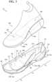
- an article of footwear 10includes a sole structure 100 and a bootie 200 attached to the sole structure 100.
- the sole structure 100is configured to provide characteristics of cushioning and responsiveness to the article of footwear 10
- the bootie 200is configured to receive a foot of a wearer to secure the foot of the wearer to the sole structure 100.
- the footwear 10may further include an anterior end 12 associated with a forward-most point of the article of footwear 10, and a posterior end 14 corresponding to a rearward-most point of the footwear 10.
- a longitudinal axis A 10 of the footwear 10extends along a length of the footwear 10 from the anterior end 12 to the posterior end 14, and generally divides the footwear 10 into a medial side 16 and a lateral side 18. Accordingly, the medial side 16 and the lateral side 18 respectively correspond with opposite sides of the footwear 10 and extend from the anterior end 12 to the posterior end 14.
- a longitudinal directionrefers to the direction extending from the anterior end 12 to the posterior end 14, while a lateral direction refers to the direction transverse to the longitudinal direction and extending from the medial side 16 to the lateral side 18.
- the article of footwear 10may be divided into one or more regions.
- the regionsmay include a forefoot region 20, a mid-foot region 22, and a heel region 24.
- the forefoot region 20may be further subdivided into a toe portion 20 T corresponding with phalanges and a ball portion 12 B associated with metatarsal bones of a foot.
- the mid-foot region 22may correspond with an arch area of the foot, and the heel region 24 may correspond with rear portions of the foot, including a calcaneus bone.
- the article of footwear 10may be further described as including a peripheral region 26 and an interior region 28, as indicated in FIG. 3 .
- the peripheral region 26is generally described as being a region between the interior region 28 and an outer perimeter of the sole structure 100. Particularly, the peripheral region 26 extends from the forefoot region 20 to the heel region 24 along each of the medial side 16 and the lateral side 18, and wraps around each of the anterior end 12 and the posterior end 14.
- the interior region 28is circumscribed by the peripheral region 26, and extends from the forefoot region 20 to the heel region 24 along a central portion of the sole structure 100. Accordingly, each of the forefoot region 20, the mid-foot region 22, and the heel region 24 may be described as including the peripheral region 26 and the interior region 28.
- Components of the article of footwear 10may be further defined in terms of a vertical position on the article of footwear 10.
- the article of footwear 10includes a plantar region 30 on the bottom of the article of footwear 10 and configured to oppose or support a plantar surface of the foot.
- a dorsal region 32is formed on an opposite side of the article 10 from the plantar region 30, and extends along a top side of the article of footwear 10 and receives a dorsal portion of the foot.
- a side region 34extends along the medial side 16 and the lateral side 18 between the plantar region 30 and the dorsal region 32 and surrounds an outer periphery of the foot.
- the sole structure 100includes a midsole 102 configured to impart properties of cushioning and responsiveness, and an outsole 104 configured to impart properties of traction and abrasion resistance.
- the midsole 102 and the outsole 104may cooperate to define a ground engaging surface 36 along the plantar region 30 of the article of footwear 10.
- the sole structure 100may further include one or more directional supports, such as a toe cap 106 disposed at the anterior end 12 of the midsole 102, a saddle 108 extending from the medial side 18 of the midsole 102, and a heel clip 110 extending from the posterior end 14 of the midsole 102.
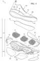
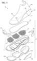
- the midsole 102includes a cushioning element 112, a plurality of cushioning particles 114 received by the cushioning element 112, and an upper barrier layer 116 attached to the top of the cushioning element 112 to enclose the cushioning particles 114 on a first side of the cushioning element 112.
- the outsole 104may include a plurality of outsole elements 118a-118c attached to an opposite side of the cushioning element 112 from the upper barrier layer 116 to enclose the cushioning particles 114 within the midsole 102.
- the cushioning element 112 of the midsole 102extends from a first end 120 disposed at the anterior end 12 of the footwear 10 to a second end 122 disposed at the posterior end 14 of the footwear 10.
- the cushioning element 112further includes a top surface 124 and a bottom surface 126 formed on an opposite side from the top surface 124. A distance between the top surface 124 and the bottom surface 126 defines a thickness of the cushioning element 112.
- An outer side surface 128extends from the top surface 124 to the bottom surface 126 and defines an outer peripheral profile of the cushioning element 112.
- the cushioning element 112further includes an inner side surface 130 spaced inwardly from the outer side surface 128 and extending continuously from the top surface 124 to the bottom surface 126 to form a channel 132 through the thickness of the cushioning element 112.
- the inner side surface 130is formed between the peripheral region 26 and the interior region 28 in the forefoot region 20, the midfoot region 22, and the heel region 24.
- the channel 132is substantially formed within the interior region 28 of the cushioning element 112, and extends continuously from a first end 134 in the forefoot region 20 to a second end 136 in the heel region 24.
- the first end 134is disposed between the toe portion 20 T and a ball portion 20 B of the forefoot region 20, such that the channel 132 extends through the ball portion 20 B , and the toe portion 20 B is supported by the top surface 124 of the cushioning element 112. Accordingly, the top surface 124 of the cushioning element 112 extends along the peripheral region 26 in the forefoot region 20, the midfoot region 22, and the heel region 24. In other examples, the channel 132 may extend through the entire forefoot region 20, such that the toe portion 20 T is also supported by the cushioning particles 114 when the sole structure 100 is assembled.
- the cushioning element 112includes one or more ribs 138a, 138b configured to separate the channel 132 into a plurality of pockets 152a-152c for receiving the cushioning particles 114.
- the one or more ribs 138a, 138bincludes a first rib 138a disposed between the forefoot region 20 and the midfoot region 22, and a second rib 138b disposed between the midfoot region 22 and the heel region 24.
- the cushioning element 112may include different numbers of the ribs 138a, 138b.
- the cushioning element 112may include three or more ribs to divide the channel 132 into four or more pockets.
- at least one of the pocketsmay be disposed within the toe portion 20 T .
- each of the ribs 138a, 138bextends across the channel 132 from a first end 140a, 140b attached to the inner side surface 130 on the medial side 16 to a second end 142a, 142b attached to the inner side surface 130 on the lateral side 18.
- the ribs 138a, 138bfurther include an upper surface 144a, 144b formed at the top surface 124 of the cushioning element 112 and a lower surface 146a, 146b formed at the bottom surface 126 of the cushioning element 112.
- the upper surface 144a, 144b of each rib 138a, 138bmay be offset or recessed from the top surface 124 of the cushioning element 112 by a distance.
- the lower surface 146a, 146b of each rib 138a, 138bmay be coincident with the bottom surface 126 of the cushioning element 112, and form a portion of the ground-engaging surface 36 of the sole structure 100.
- each rib 138a, 138bmay further include an anterior side surface 148a, 148b extending from the upper surface 144a, 144b towards the lower surface 146a, 146b and facing the anterior end 12, and a posterior side surface 150a, 150b extending from the upper surface 144a, 144b towards the lower surface 146a, 146b and facing the posterior end 14.
- a distance from the anterior side surface 146a, 146b to the posterior side surface 148a, 148bdefines a width W 138a , W 138b of each rib 138a, 138b.
- each rib 138a, 138bis configured such that a stiffness progressively increases as compression towards the lower surface 146 increases.
- the anterior side surface 148a of the first rib 138a and the posterior side surface 148b of the second rib 138bmay have concave profiles, while the posterior side surface 150a of the first rib 138a and the anterior side surface 148b of the second rib 138b may be substantially straight.
- the ribs 138a, 138bseparate the channel 132 into a forefoot pocket 152a disposed on an anterior side of the first rib 138a, a midfoot pocket 152b disposed between the first rib 138a and the second rib 138b, and a heel pocket 152c disposed on a posterior side of the second rib 138b.
- Each of the forefoot pocket 152a, the midfoot pocket 152b, and the heel pocket 152cextends from a respective top opening 154a-154c formed through the top surface 124 to a bottom opening 156a-156c formed through the bottom surface 126.
- the widths W 138a , W 138b of the ribs 138a, 138bmay progressively increase in a direction from the top surface 124 to the bottom surface 126. Accordingly, a cross-sectional area of one or more of the pockets 152a-152c may progressively decrease along the direction from the top surface 124 to the bottom surface 126.
- the top surface 124 and the bottom surface 126 of the cushioning element 112include a plurality of recesses for receiving covers or enclosures for the pockets 152a-152c.
- the top surface 124includes a top recess 158 extending outwardly from the inner side surface 130 of the cushioning element 112.
- a peripheral profile of the top recess 158corresponds to an outer peripheral profile of the upper barrier layer 116 and a depth of the top recess 158 corresponds to a thickness of the upper barrier layer 116.
- the top recess 158is configured to receive the upper barrier layer 116 such that a top surface of the upper barrier layer 116 is substantially flush with the top surface 124 of the cushioning element 112 when the sole structure 100 is assembled, as shown in FIG. 7 .
- the bottom surface 126 of the cushioning element 112further includes a plurality of outsole recesses 160a-160c corresponding to the bottom openings 156a-156c of each of the pockets 152a-152c.
- each of the outsole recesses 160a-160cmay extend outwardly from one of the bottom openings 156a-156c to provide a receptacle for receiving one of the outsole elements 118a-118c.
- the outsole recesses 160a-160care configured with a depth corresponding to thicknesses of the respective outsole elements 118a-118c, while a peripheral profile of each outsole recess 160a-160c corresponds to a peripheral profile of one of the outsole elements 118a-118c.
- the cushioning element 112may be provided with one or more windows 162a, 162b formed through the peripheral region 26 of the cushioning element 112 and into one of the pockets 152a-152c.
- the cushioning element 112includes a first pair of windows 162a, 162b formed in the bottom surface 126 and extending through the peripheral region 26 from the outer side surface 128 to the inner side surface 130.
- the windows 162a, 162binclude a first window 162a extending into the midfoot pocket 152b on the medial side 16, and a second window 162b extending into the midfoot pocket 152b on the lateral side 18.
- Each of the windows 162a, 162bprovides a space through with the cushioning particles 114 can flow between the cushioning element 112 and the outsole 104 when the sole structure 100 is assembled. Accordingly, cushioning particles 114 may be disposed against, and visible through, the midfoot outsole element 118b along the outer periphery of the sole structure 100.
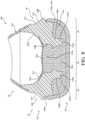
- the heel region 24 of the cushioning element 112may include a ramp surface 164 formed around the bottom opening 156c of the heel pocket 152c.
- the ramp surface 164extends in a direction from the bottom surface 126 towards the top surface 124, such that the ramp surface 164 is spaced apart from a ground plane GP in the heel region.
- the ramp surface 164is formed at an oblique angle ⁇ relative to the ground-engaging surface 36 of the sole structure 100, such that the ramp surface 164 extends away from the ground plane GP at the angle ⁇ along a direction from the midfoot region 22 to the posterior end 14.
- the heel region 24 of the cushioning elementfurther includes one or more pillars 166a-166c projecting downwardly from the ramp surface 164. Accordingly, each of the pillars 166a-166c extends from a proximal end 168a-168c attached at the ramp surface 164 to a terminal, distal end 170a-170c formed at an opposite end of the pillar 166a-166c.
- the distal ends 170a-170care configured to interface with the heel outsole element 118c when the sole structure 100 is assembled, thereby providing support to the article of footwear 10 in the heel region 24. Accordingly, the distal ends 170a-170c may by understood as forming a portion of the bottom surface 126 of the cushioning element 112.
- a cross-sectional area of one or more of the pillars 166a-166cmay decrease along a direction from the proximal end 168a-168c to the distal end 170a-170c.
- at least one of a width and/or a length of the one or more pillars 166a-166cmay taper along a height direction from the proximal end 168a-168c to the distal end 170a-170c.
- the one or more pillars 166a-166cincludes a series of pillars 166a-166c arranged around the bottom opening 156c of the heel pocket 152c.
- the series of pillars 166a-166cincludes a medial pillar 166a disposed on the medial side 16 of the bottom opening 156c, a lateral pillar 166b disposed on the lateral side 18 of the bottom opening 156c, and a posterior pillar 166c disposed on a posterior end of the bottom opening 156c.
- the pillars 166a-166care aligned in series along an outer periphery of the bottom opening 156c.
- the pillars 166a-166care arranged in series along a horseshoe-shaped, arcuate path or axis A 166 corresponding to the curvature of the posterior end 14 of the sole structure 100.
- the pillars 166a-166cmay be spaced apart from each other along the axis A 166 to provide a series of gaps 172 between adjacent pillars 166a-166c. These gaps 172 maximize flow of the cushioning particles 114 within the heel region 24, as the cushioning particles 114 are able to flow freely between adjacent ones of the pillars 166a-166c.
- the heel region 24 of the cushioning elementmay include a relief 167 formed in the outer side surface 128.
- the relief 167extends continuously around the heel region 24 from a first end on the medial side 16 to a second end on the lateral side 18.
- the relief 167is configured to allow the peripheral region 26, and particularly, the outer side surface 128, to act as a spring or living hinge, thereby allowing the cushioning element 112 to compress in the heel region 24.
- the cushioning element 112is formed of one or more resilient polymeric materials, such as foam or rubber, to impart properties of cushioning, responsiveness, and energy distribution to the foot of the wearer.
- the cushioning element 112is formed as a composite, whereby different components of the cushioning element 112 are formed of different materials to impart different properties to the sole structure 100.
- the peripheral region 26 of the cushioning element 112may be formed of a first polymeric material having a first durometer, while the ribs 138a-138b, or at least a top portion of the ribs 138a-138b, are formed of a second polymeric material having a lower durometer than the peripheral region 26. Accordingly, the ribs 138a-138b can be more easily compressed, and will provide a softer feel along the footbed to minimize point loads along the plantar surface of the foot.
- Example resilient polymeric materials for the cushioning element 112may include those based on foaming or molding one or more polymers, such as one or more elastomers (e.g., thermoplastic elastomers (TPE)).
- the one or more polymersmay include aliphatic polymers, aromatic polymers, or mixtures of both; and may include homopolymers, copolymers (including terpolymers), or mixtures of both.
- the one or more polymersmay include olefinic homopolymers, olefinic copolymers, or blends thereof.
- olefinic polymersinclude polyethylene, polypropylene, and combinations thereof.
- the one or more polymersmay include one or more ethylene copolymers, such as, ethylene-vinyl acetate (EVA) copolymers, EVOH copolymers, ethylene-ethyl acrylate copolymers, ethylene-unsaturated mono-fatty acid copolymers, and combinations thereof.
- EVAethylene-vinyl acetate
- the one or more polymersmay include one or more polyacrylates, such as polyacrylic acid, esters of polyacrylic acid, polyacrylonitrile, polyacrylic acetate, polymethyl acrylate, polyethyl acrylate, polybutyl acrylate, polymethyl methacrylate, and polyvinyl acetate; including derivatives thereof, copolymers thereof, and any combinations thereof.
- polyacrylatessuch as polyacrylic acid, esters of polyacrylic acid, polyacrylonitrile, polyacrylic acetate, polymethyl acrylate, polyethyl acrylate, polybutyl acrylate, polymethyl methacrylate, and polyvinyl acetate; including derivatives thereof, copolymers thereof, and any combinations thereof.
- the one or more polymersmay include one or more ionomeric polymers.
- the ionomeric polymersmay include polymers with carboxylic acid functional groups, sulfonic acid functional groups, salts thereof (e.g., sodium, magnesium, potassium, etc.), and/or anhydrides thereof.
- the ionomeric polymer(s)may include one or more fatty acid-modified ionomeric polymers, polystyrene sulfonate, ethylene-methacrylic acid copolymers, and combinations thereof.
- the one or more polymersmay include one or more styrenic block copolymers, such as acrylonitrile butadiene styrene block copolymers, styrene acrylonitrile block copolymers, styrene ethylene butylene styrene block copolymers, styrene ethylene butadiene styrene block copolymers, styrene ethylene propylene styrene block copolymers, styrene butadiene styrene block copolymers, and combinations thereof.
- styrenic block copolymerssuch as acrylonitrile butadiene styrene block copolymers, styrene acrylonitrile block copolymers, styrene ethylene butylene styrene block copolymers, styrene ethylene butadiene styrene block
- the one or more polymersmay include one or more polyamide copolymers (e.g., polyamide-polyether copolymers) and/or one or more polyurethanes (e.g., crosslinked polyurethanes and/or thermoplastic polyurethanes).
- polyamide copolymerse.g., polyamide-polyether copolymers
- polyurethanese.g., crosslinked polyurethanes and/or thermoplastic polyurethanes.
- polyurethanescan contain additional groups such as ester, ether, urea, allophanate, biuret, carbodiimide, oxazolidinyl, isocynaurate, uretdione, carbonate, and the like, in addition to urethane groups.
- the one or more polymersmay include one or more natural and/or synthetic rubbers, such as butadiene and isoprene.
- the foamed materialmay be foamed using a physical blowing agent which phase transitions to a gas based on a change in temperature and/or pressure, or a chemical blowing agent which forms a gas when heated above its activation temperature.
- the chemical blowing agentmay be an azo compound such as adodicarbonamide, sodium bicarbonate, and/or an isocyanate.
- the foamed polymeric materialmay be a crosslinked foamed material.
- a peroxide-based crosslinking agentsuch as dicumyl peroxide may be used.
- the foamed polymeric materialmay include one or more fillers such as pigments, modified or natural clays, modified or unmodified synthetic clays, talc glass fiber, powdered glass, modified or natural silica, calcium carbonate, mica, paper, wood chips, and the like.
- the resilient polymeric materialmay be formed using a molding process.
- the uncured elastomere.g., rubber
- a curing packagesuch as a sulfur-based or peroxide-based curing package, calendared, formed into shape, placed in a mold, and vulcanized.
- the resilient polymeric materialwhen the resilient polymeric material is a foamed material, the material may be foamed during a molding process, such as an injection molding process.
- a thermoplastic polymeric materialmay be melted in the barrel of an injection molding system and combined with a physical or chemical blowing agent and optionally a crosslinking agent, and then injected into a mold under conditions which activate the blowing agent, forming a molded foam.
- the foamed materialwhen the resilient polymeric material is a foamed material, the foamed material may be a compression molded foam. Compression molding may be used to alter the physical properties (e.g., density, stiffness and/or durometer) of a foam, or to alter the physical appearance of the foam (e.g., to fuse two or more pieces of foam, to shape the foam, etc.), or both.
- Compression moldingmay be used to alter the physical properties (e.g., density, stiffness and/or durometer) of a foam, or to alter the physical appearance of the foam (e.g., to fuse two or more pieces of foam, to shape the foam, etc.), or both.
- the compression molding processdesirably starts by forming one or more foam preforms, such as by injection molding and foaming a polymeric material, by forming foamed particles or beads, by cutting foamed sheet stock, and the like.
- the compression molded foammay then be made by placing the one or more preforms formed of foamed polymeric material(s) in a compression mold, and applying sufficient pressure to the one or more preforms to compress the one or more preforms in a closed mold.
- the moldis closed, sufficient heat and/or pressure is applied to the one or more preforms in the closed mold for a sufficient duration of time to alter the preform(s) by forming a skin on the outer surface of the compression molded foam, fuse individual foam particles to each other, permanently increase the density of the foam(s), or any combination thereof.
- the moldis opened and the molded foam article is removed from the mold.
- the outsole 104may include one or more discrete outsole elements 118a-118c that are separate from one another.
- the outsole elements 118a-118cmay be formed from a transparent or translucent material.
- the outsole elements 118a-1 18cmay be formed from a durable material such as, for example, rubber and may be attached to the bottom surface 126 of the cushioning element 112 at the respective recesses 160a-160c. Accordingly, the outsole elements 118a-118c may be attached to the bottom surface 126 of the cushioning element 112 proximate to the bottom openings 156a-156c respectively associated with the first pocket 152a, the second pocket 152b, and the third pocket 152c.
- one or more of the outsole elements 118a-118cmay include perforations formed therethrough, thereby allowing air to move into the channel 132 through the outsole 104 as the cushioning particles 114 within the sole structure 100 are compressed or decompressed.
- the outsole elements 118a-118cmaybe separated from one another along a length of the sole structure 100 in a direction substantially parallel to the longitudinal axis L 10 . While the outsole 104 is described and shown as including individual portions that are spaced apart from one another, the outsole 104 could alternatively have a unitary construction that extends generally across the entire bottom surface 126 of the cushioning element 112 such that the outsole 104 extends continuously between the anterior end 12 and the posterior end 14 and between the medial side 16 and the lateral side 18. Regardless of the particular construction of the outsole 104 (i.e., unitary or discrete portions), the outsole 104 may include treads that extend from the outsole 104 to provide increased traction with a ground surface during use of the article of footwear 10.
- Forming the outsole 104 from a transparent or translucent materialallows the pockets 152a-152c to be viewed through the outsole 104 when the outsole 104 is attached to the cushioning element 112 at the bottom surface 126. Further, because the cushioning particles 114 substantially fill the respective pockets 152a-152c, the interiors of the pockets 152a-152c and, thus, the cushioning particles 114 disposed therein are likewise visible at the bottom openings 156a-156c of the cushioning element 112 through the material of the outsole 104. Accordingly, the cushioning particles 114 residing within the respective pockets 152a-152c of the cushioning element 112 are visible through the outsole 104 at the bottom openings 156a-156c.
- the sole structure 100includes volumes of the cushioning particles 114 disposed directly within each of the pockets 152a-152c.
- the cushioning particles 114are not contained within an intermediate chamber or container, but are loosely disposed within each of the pockets 152a-152c.
- each of the pockets 152a-152cis over-filled with a volume of the cushioning particles 114, such that the volume of cushioning particles 114 in each of the pockets 152a-152c extends above the upper surfaces 144a, 144b of the respective ribs 138a, 138b. Accordingly, the cushioning particles 114 will cooperate with the top surface 124 of the cushioning element 112 to support the plantar surface of the foot.
- the cushioning particles 114may be used to enhance the functionality and cushioning characteristics of the sole structure 100.
- the cushioning particles 114 contained within the pockets 152a-152cmay include polymeric beads.
- the cushioning particles 114may be formed of any one of the resilient polymeric materials discussed above with respect to the cushioning element 112.
- the cushioning particles 114are formed of a foamed polyurethane (TPU) material, and have a substantially spherical shape.
- the foam beads defining the cushioning particles 114may have approximately the same size and shape or, alternatively, may have at least one of a different size and shape. Regardless of the particular size and shape of the cushioning particles 114, the cushioning particles 114 cooperate with the cushioning element 112 and the outsole 104 to provide the article of footwear 10 with a cushioned and responsive performance during use.
- the upper barrier layer 116is received within the top recess 158 of the cushioning element 112 to enclose the cushioning particles 114 within each of the respective pockets 152a-152c. Accordingly, the upper barrier layer 116 cooperates with the top surface 124 of the cushioning element 112 to form a support surface of the sole structure 100.
- the upper barrier layer 116is formed of an air-permeable material, thereby allowing air to move in and out of the respective pockets 152a-152c as the cushioning particles 114 move between compressed and relaxed states.
- the upper barrier layer 116is formed of a knitted fabric material having a relatively high modulus of elasticity to allow the upper barrier layer 116 to stretch into the pockets 152a-152c when the sole structure 100 is compressed by the foot during use.
- Incorporation of the cushioning particles 114 into the article of footwear 10provides a degree of comfort and cushioning to a foot of a user during use. For example, when a force is applied on the upper barrier layer during use of the article footwear by a foot of a user, the force causes the upper barrier layer 116 to flex and stretch, thereby allowing the foot of the user to engage and displace the cushioning particles 114 disposed within the pockets 152a-152c. Such movement of the upper barrier layer 116 also compresses a material of the cushioning element 112 generally surrounding the pockets 152a-152c which, in turn, absorbs forces associated with a walking or running movement.
- the toe cap 106, the saddle 108, and the heel clip 110are each formed of a polymeric material having a greater rigidity than the cushioning element 112, and extend upwardly from the outer side surface 128 to provide areas of additional support to the bootie 200.
- the toe cap 106is attached at the anterior end 12 and extends around the toe portion 20 T from the medial side 16 to the lateral side 18.
- the saddle 108is attached at the lateral side 18 in the midfoot region 22.
- the heel clip 110is attached at the posterior end 14 and extends around the heel region 24 from the medial side 16 to the lateral side 18.
- a bootie 200 for the article of footwear 10is shown.
- the bootie 200may be formed from one or more materials that are stitched or adhesively bonded together to form the interior void configured to receive and secure a foot for support on the sole structure 100.
- Suitable materials of the bootie 200may include, but are not limited to, mesh, textiles, foam, leather, and synthetic leather. The materials may be selected and located to impart properties of durability, air-permeability, wear-resistance, flexibility, and comfort.
- the bootie 200includes a strobel 202 and an upper 204 attached to an outer periphery of the strobel 202 along a peripheral seam 206 to define the interior void.
- stitching or adhesivesmay secure the strobel 202 to the upper 204.
- An ankle openingis formed at the heel region 24 and may provide access to the interior void.
- the ankle openingmay receive a foot to secure the foot within the void and facilitate entry and removal of the foot to and from the interior void.
- one or more fastenersextend along the upper 204 to adjust a fit of the interior void around the foot and to accommodate entry and removal of the foot therefrom.
- the fastenersmay include laces, straps, cords, hook-and-loop, or any other suitable type of fastener.
- the bootie 200further includes an interior reinforcement member 208 configured to be attached to an interior surface of the strobel 202, within the interior void.
- An exterior reinforcement member 210is disposed on an opposite side of the strobel 202 from the interior reinforcement member 208, such that the exterior reinforcement member 210 opposes the sole structure 100 when the article of footwear 10 is assembled.
- the strobel 202includes a footbed 212 and a peripheral wall 214 extending transversely (i.e., not parallel) from the footbed 212.
- the footbed 212is substantially flat, but may be contoured to conform to a profile of the bottom surface (e.g., plantar) of the foot.
- the footbed 212includes an interior surface 216 and an exterior surface 218 formed on an opposite side of the footbed 212 from the interior surface 216.
- the interior surface 216is configured to enclose a bottom portion of the interior void and to support a plantar surface of the foot when the foot is disposed within the interior void.
- the exterior surface 218is configured to oppose the sole structure 100, and may be attached to the top surface 124 of the cushioning element 112 and the upper barrier layer 116 when the bootie 200 is assembled to the sole structure 100.
- An outer periphery of the footbed 212is defined by a peripheral edge 220, which corresponds to a peripheral profile of a plantar surface of a foot.
- the peripheral wall 214 of the strobel 202extends upwardly from a first end 222 attached to the peripheral edge 220 of the footbed 212 to a distal, upper terminal edge 224 spaced apart from the footbed 212.
- the peripheral edge 220 of the footbed 212 and the first end 222 of the peripheral wall 214may cooperate to provide an arcuate or concave transition between a substantially flat portion of the footbed 212 and a substantially upright portion of the peripheral wall 214.
- the footbed 212 and the peripheral wall 214cooperate to define a cavity 226 for receiving the foot.
- the peripheral wall 214may extend only partially around the peripheral edge 220 of the footbed 212 such that at least a portion of the peripheral edge 220 is exposed.
- the peripheral edge 220 of the footbed 212 and the first end 222 of the peripheral wall 214are integral, such that the footbed 212 and the peripheral wall 214 are formed as a substantially continuous piece having no pronounced seams.
- the strobel 202is formed of a single piece of flexible and/or elastic material.
- the strobel 202may be constructed of different materials having different properties, where the materials are joined to each other in a seamless manner to provide a substantially continuous and flush piece of material.
- a distance from the first end 222 of the peripheral wall 214 to the upper terminal edge 224 of the peripheral wall 214defines a height H 214 of the peripheral wall 214 around the footbed 212.
- the height H 214 of the peripheral wall 214may be variable along the outer perimeter of the strobel 202.
- the peripheral wall 214may include one or more portions having a greater height H 214 than other portions.
- the peripheral wall 214is formed with a pair of wings 228 extending from opposite sides of the footbed 212. A first one of the wings 228 extends from the medial side 16 of the footbed 212 and a second one of the wings 228 extends from the lateral side 18 of the footbed 212.
- Each of the wings 228extends from a first end 230 in the midfoot region 22 to a second end 232 in the heel region 24. As shown in FIGS. 1 and 2 , a height H 214 of the peripheral wall 214 along the wings 228 is selected so that when the article of footwear 10 is assembled, the wings 228 extend above a top edge of the sole structure 100. Accordingly, portions of the peripheral seam 206 extending along the wings 228 are exposed above the sole structure 100.
- the upper 204includes a sidewall 234 configured to surround a dorsal region of the foot when the article of footwear 10 is donned by the wearer.
- the sidewall 234extends from a lower terminal edge 236 along the bottom of the upper 204 to a collar 238 defining the ankle opening at the top of the upper 204.
- a shape of the lower terminal edge 236corresponds to the shape of the upper terminal edge 224 of the strobel 202, such that the lower terminal edge 236 can be mated with the upper terminal edge 224 to form the peripheral seam 206 when the bootie 200 is assembled.
- the peripheral seam 206extends continuously around the outer periphery of the bootie 200 to connect the strobel 202 to the upper 204. As discussed above, because the strobel 202 includes the peripheral wall 214, the peripheral seam 206 is positioned above the footbed 212, away from the plantar surface of the foot. More particularly, the peripheral seam 206 is arranged along sides 16, 18 of the bootie 200 in the midfoot region 22 so that vertical and lateral forces imparted on the sole structure 100 during movement are not applied to the peripheral seam 206 and the foot. Accordingly, the underfoot feel of the bootie 200 is improved.
- the peripheral seam 206may include a first stitching 240a in a first portion and a second stitching 240b in a second portion.
- the peripheral seam 206includes the first stitching 240a extending through the midfoot region 22 and around the heel region 24 and includes the second stitching 240b extending from the midfoot region 22 and around the forefoot region 20.
- the first stitching 240amay be an overlock stitching (e.g., surge stitching) and the second stitching may be a lock stitching (e.g., straight stitching).
- the bootie 200includes the interior reinforcement member 208 and the exterior reinforcement member 210 attached to opposite sides of the footbed 212 from each other.
- the reinforcement members 208, 210are each formed of a material having a greater stiffness than the material forming the footbed 212 of the strobel 202. Accordingly, the reinforcement members 208, 210 provide a desired degree of support and stability to the footbed 212.
- Each of the reinforcement members 208, 210may be attached to the strobel 202 by adhesively bonding the reinforcement members 208, 210 to respective ones of the surfaces 216, 218 of the strobel 202.
- the interior reinforcement member 208is disposed on the interior surface 216 of the footbed 212 and extends continuously from a first end 242 disposed in the midfoot region 22 to a second end 244 at the posterior end 14. Likewise, the interior reinforcement member 208 extends continuously from the medial side 16 to the lateral side 18 of the footbed 212. Accordingly, the interior reinforcement member 208 is formed as a substantially continuous element covering the midfoot region 22 and the heel region 24 of the interior surface 216 of the footbed 212.
- the exterior reinforcement member 210is disposed on the exterior surface 218 of the footbed 212 and extends continuously from the forefoot region 20 to the posterior end 14. However, unlike the interior reinforcement member 208, which covers the peripheral region 26 and the interior region 28 of the footbed 212, the exterior reinforcement member 210 extends only along the peripheral region 26 of the exterior surface 218.
- the exterior reinforcement member 210is U-shaped or horseshoe shaped and extends along the peripheral region 26 from a first end 245a disposed in the forefoot region 20 on the medial side 16 to a second end 245b disposed in the forefoot region 20 on the lateral side 18.
- the exterior reinforcement member 210includes a medial segment 246 extending along the peripheral region 26 on the medial side 16, a lateral segment 248 extending along the peripheral region on the lateral side 18, and a posterior segment 250 extending around the posterior end 14 and connecting the medial segment 246 and the lateral segment 248.
- the components 202, 204, 208, 210 of the bootie 200may be formed of different materials to provide desired characteristics.
- the strobel 202may be formed of a first material having first material properties and the upper 204 may be formed of one or more second materials having second material properties.
- the first material forming the strobel 202has as higher modulus of elasticity than the second material(s) forming the upper 204.
- the reinforcement members 208, 210are formed of a third material having a greater stiffness than the material of the strobel 202.
- an article of footwear 10ais provided and includes a sole structure 100a and the bootie 200 attached to the sole structure 100a.
- like reference numeralsare used hereinafter and in the drawings to identify like components while like reference numerals containing letter extensions are used to identify those components that have been modified.
- the midsole 102a of the sole structure 100aincludes a cushioning element 112a that is configured differently than the cushioning element 112 discussed above.
- the cushioning element 112aincludes a channel 132a that extends along the entire length of the interior region 28 of the cushioning element 112a.
- the channel 132aextends from a first end 134 at the anterior end 12 of the cushioning element 112a to a second end 136 at the posterior end of the cushioning element 112a.
- the channel 132ais separated into four pockets 152d-152g by three ribs 138c-138e spaced along the length of the cushioning element 112a.
- each of the ribsextends from a first end 140c-140e attached to the inner side surface 130 on the medial side 16, to a second end 142c-142e attached to the inner side surface 130 on the lateral side 18.
- each of the ribs 138c-138eincludes an upper surface 144c-144e formed at the top surface 124 of the cushioning element 112a and a lower surface 146c-146e formed at the bottom surface 126 of the cushioning element 112a.
- the upper surface 144a-144c of each rib 138c-138emay be offset or recessed from the top surface 124 of the cushioning element 112a by a distance.
- each rib 138c-138emay be coincident with the bottom surface 126 of the cushioning element 112a, and may form a portion of the ground-engaging surface 36 of the sole structure 100a.
- Each rib 138c-138emay further include an anterior side surface 148c-148e extending from the upper surface 144c-144e towards the lower surface 146c-146e and facing the anterior end 12, and a posterior side surface 150c-150e extending from the upper surface 144c-144e towards the lower surface 146c-146e and facing the posterior end 14.
- a first one of the ribs 138cis disposed between the toe portion 20 T and the ball portion 20 B of the forefoot region 20.
- a second one of the ribs 138dis disposed between the forefoot region 20 and the midfoot region 22, and a third one of the ribs 138e is disposed between the midfoot region 22 and the heel region 24. Accordingly, the ribs 138c-138e separate the channel 132a into a toe pocket 152d, a ball pocket 152e, a midfoot pocket, 152f, and a heel pocket 152g.
- the first rib 138cextends from the medial side 16 to the lateral side 18 at a substantially orthogonal angle to the longitudinal axis A 10a of the article of footwear 10.
- the second rib 138dextends from the medial side 16 to the lateral side 18 at a first oblique angle to the longitudinal axis A 10a , such that the first end 144d is positioned closer to the anterior end 12 than the second end 146d.
- the third rib 138eextends from the medial side 16 to the lateral side 18 at a second oblique angle to the longitudinal axis A 10a , such that the first end 144e is disposed closer to the posterior end 14 than the second end 146e. Accordingly, the second rib 138d and the third rib 138e converge with each other along the direction from the medial side 16 to the lateral side 18.
- the sole structure 100a of FIGS. 15-18may include the pillars 166a-166c arranged in series around the heel region 24.
- the pillars 166a-166care spaced apart from each other by the gaps 172, thereby allowing the cushioning particles to migrate from the heel pocket 152g towards the outer side surface 128 of the cushioning element 112a.
- the cushioning particles 114 of the sole structure 100amay optionally be contained within one or more chambers 174a-174c, which are received within the pockets 152d-152e.
- the chambers 174a-174care formed as part of a bladder 176 having the upper barrier layer 116 and a lower barrier layer 180 joined together with each other at discrete locations to define a web area 182 and the chambers 174a-174c. Accordingly, the chambers 174a-174c are all connected to each other by the web area 182.
- one or more of the chambers 174a-174cmay be formed separately from other ones of the chambers 174a-174c.
- the upper barrier layer 116 and the lower barrier layer 180may be formed from flexible materials that allow the lower barrier layer 180 and the upper barrier layer 116 to stretch and move during use of the article of footwear 10 when the sole structure 100 is subjected to a force from a foot of a user.
- the upper barrier layer 116 and the lower barrier layer 180are formed from different materials.
- the lower barrier layer 180may be formed from a polymer material such as thermoplastic polyurethane (TPU). Forming the lower barrier layer 180 from TPU allows the lower barrier layer 180 to be formed from an impermeable material and, in some configurations, allows the lower barrier layer 180 to be formed from an optically clear and/or translucent material.
- TPUthermoplastic polyurethane
- the upper barrier layer 116may be formed from a flexible material such as, for example, spandex. Forming the upper barrier layer 116 from a flexible material such as spandex also allows the upper barrier layer 116 to be permeable. Forming the upper barrier layer 116 from a permeable material permits fluid communication through the upper barrier layer 116 into each of the chambers 174a-174c, thereby permitting air circulation from an area external to the bladder 176 into the chambers 174a-174c.
- the upper barrier layer 116may be attached to the lower barrier layer 180 via an adhesive.
- the adhesivemay be a hot melt adhesive and may surround a perimeter of each of the chambers 174a-174c. As such, the adhesive joins the material of the upper barrier layer 116 to the material of the lower barrier layer 180 between each of the chambers 174a-174c, thereby defining an interior void within each chamber 174a-174c between the upper barrier layer 116 and the lower barrier layer 180.
- the web area 182may extend between each chamber 174a-174c as well as around an outer perimeter of the bladder 176, as shown in FIG. 17 .
- the web area 182may include a thickness that is substantially equal to a depth of the top recess 158 of the cushioning element 112a relative to the top surface 124 of the cushioning element 112a.
- the overall shape of the bladder 176is defined by the web area 182 at a perimeter of the bladder 176 and may include a peripheral profile that is substantially the same as a peripheral profile of the top recess 158, as formed into the top surface 124. Accordingly, when the bladder 176 is inserted into the midsole, an upper surface of the bladder 176 is substantially flush with the top surface 124 of the cushioning element 112, thereby providing a uniform surface that receives the footbed 212 of the bootie 200. Providing a uniform surface that opposes the footbed 212 provides a degree of comfort to a foot of a user by preventing the user from feeling a transition or junction between the cushioning element 112 and the bladder 176.
- the pockets 152d-152greceives the cushioning particles 114 directly, without the cushioning particles 114 being contained within an intermediate chamber 174a-174c.
- the cushioning particles 114are provided directly to the heel pocket 152g, such that the cushioning particles 114 are loosely contained within the heel pocket 152g by enclosing a bottom portion of the heel pocket 152g with the outsole 104a and enclosing a top portion of the heel pocket 152g with the upper barrier layer 116 of the bladder 176.
- the lower barrier layer 180terminates at the third rib 138e
- the upper barrier layer 116extends continuously to the posterior end 14 to cover the top opening 154g of the heel pocket 152g.
- the outsole 104aincludes a plurality of outsole elements 118d-118f attached to the bottom surface 126 of the cushioning element 112a to enclose the bottom openings 156d-156g of the pockets 152d-152g.
- one or more of the pockets 152d-152gmay not include a bottom opening and, therefore, no outsole element is associated with the pocket.
- the midfoot pocket 152fdoes not include a bottom opening, such that the lower portion of the midfoot pocket 152f is fully enclosed by the cushioning element 112a.
- the outsole 104aincludes a toe outsole element 118d, a ball outsole element 118e, and a heel outsole element 118f.
- one or more of the outsole elements 118d-118fmay have perforations 184 formed therethrough, which allow air to move in and out of the pockets 152d-152g when the cushioning particles 114 are compressed.
- the perforations 184are formed in the heel outsole element 118f to allow air to move in and out of the heel pocket 152g.
- perforationsare unnecessary in the outsole elements 118d, 118e associated with the pockets 152d, 152e having the impermeable lower barrier layer 180, as air would be unable to move through the lower barrier layer 180.
Landscapes
- Chemical & Material Sciences (AREA)
- Engineering & Computer Science (AREA)
- Materials Engineering (AREA)
- Health & Medical Sciences (AREA)
- Epidemiology (AREA)
- General Health & Medical Sciences (AREA)
- Public Health (AREA)
- Footwear And Its Accessory, Manufacturing Method And Apparatuses (AREA)
Description
- The present disclosure relates to articles of footwear having a sole structure incorporating particulate matter.
- This section provides background information related to the present disclosure which is not necessarily prior art.
- Articles of footwear conventionally include an upper and a sole structure. The upper may be formed from any suitable material(s) to receive, secure, and support a foot on the sole structure. The upper may cooperate with laces, straps, or other fasteners to adjust the fit of the upper around the foot. A bottom portion of the upper, proximate to a bottom surface of the foot, attaches to the sole structure.
- Sole structures generally include a layered arrangement extending between a ground surface and the upper. One layer of the sole structure includes an outsole that provides abrasion-resistance and traction with the ground surface. The outsole may be formed from rubber or other materials that impart durability and wear-resistance, as well as enhance traction with the ground surface. Another layer of the sole structure includes a midsole disposed between the outsole and the upper. The midsole provides cushioning for the foot and is generally at least partially formed from a polymer foam material that compresses resiliently under an applied load to cushion the foot by attenuating ground-reaction forces. The midsole may define a bottom surface on one side that opposes the outsole and a footbed on the opposite side that may be contoured to conform to a profile of the bottom surface of the foot. Sole structures may also include a comfort-enhancing insole or a sockliner located within a void proximate to the bottom portion of the upper.
- Midsoles using polymer foam materials are generally configured as a single slab that compresses resiliently under applied loads, such as during walking or running movements. Generally, single-slab polymer foams are designed with an emphasis on balancing cushioning characteristics that relate to softness and responsiveness as the slab compresses under gradient loads. Polymer foams providing cushioning that is too soft will decrease the compressibility and the ability of the midsole to attenuate ground-reaction forces after repeated compressions. Conversely, polymer foams that are too hard and, thus, very responsive, sacrifice softness, thereby resulting in a loss in comfort. While different regions of a slab of polymer foam may vary in density, hardness, energy return, and material selection to balance the softness and responsiveness of the slab as a whole, creating a single slab of polymer foam that loads in a gradient manner from soft to responsive is difficult to achieve.
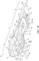
US 2006/010717 A1 A describes that a therapeutic device includes a supporting member that continuously and flexibly supports and bounds a plurality of small sized hard surfaced force members that support a user's foot during movement without clumping.FIG. 1 is an lateral elevation view of an article of footwear in accordance with the principles of the present disclosure;FIG. 2 is a medial elevation view of the article of footwear ofFIG. 1 ;FIG. 3 is an exploded perspective view of the article of footwear ofFIG. 1 , showing a sole structure and a bootie of the article of footwear;FIG. 4 is an exploded bottom perspective view of the article of footwear ofFIG. 1 , showing the sole structure exploded from the bootie;FIG. 5 is an exploded top perspective view of the article of footwear ofFIG. 1 , showing the sole structure exploded from the bootie;FIG. 6 is a bottom plan view of the article of footwear ofFIG. 1 ;FIG. 7 is a cross-sectional view of a cushioning member of the article of footwear ofFIG. 1 taken along Line 7-7 ofFIG. 6 ;FIG. 8 is a cross-sectional view of a cushioning member of the article of footwear ofFIG. 1 taken along Line 8-8 ofFIG. 6 ;FIG. 9 is a top perspective view of a cushioning element of the article of footwear ofFIG. 1 ;FIG. 10 is a bottom perspective view of the cushioning element ofFIG. 9 ;FIG. 11 is a top plan view of the cushioning element ofFIG. 9 ;FIG. 12 is a bottom plan view of the cushioning element ofFIG. 9 ;FIG. 13 is a lateral side elevation view of a bootie of the article of footwear ofFIG. 1 ;FIG. 14 is an exploded top perspective view of the bootie ofFIG. 13 ;FIG. 15 is an bottom perspective view of an article of footwear in accordance with the principles of the present disclosure;FIG. 16 is a top plan view of a sole structure of the article of footwear ofFIG. 15 ;FIG. 17 is a cross-sectional view of the article of footwear ofFIG. 15 ; andFIG. 18 is an exploded plan view of the sole structure of the article of footwear ofFIG. 15 .- Corresponding reference numerals indicate corresponding parts throughout the drawings.
- The terminology used herein is for the purpose of describing particular exemplary configurations only and is not intended to be limiting. The terms "comprises," "comprising," "including," and "having," are inclusive and therefore specify the presence of features, steps, operations, elements, and/or components, but do not preclude the presence or addition of one or more other features, steps, operations, elements, components, and/or groups thereof. The method steps, processes, and operations described herein are not to be construed as necessarily requiring their performance in the particular order discussed or illustrated, unless specifically identified as an order of performance. Additional or alternative steps may be employed.
- When an element or layer is referred to as being "on," "engaged to," "connected to," "attached to," or "coupled to" another element or layer, it may be directly on, engaged, connected, attached, or coupled to the other element or layer, or intervening elements or layers may be present. In contrast, when an element is referred to as being "directly on," "directly engaged to," "directly connected to," "directly attached to," or "directly coupled to" another element or layer, there may be no intervening elements or layers present. Other words used to describe the relationship between elements should be interpreted in a like fashion (e.g., "between" versus "directly between," "adjacent" versus "directly adjacent," etc.). As used herein, the term "and/or" includes any and all combinations of one or more of the associated listed items.
- The terms first, second, third, etc. may be used herein to describe various elements, components, regions, layers and/or sections. These elements, components, regions, layers and/or sections should not be limited by these terms. These terms may be only used to distinguish one element, component, region, layer or section from another region, layer or section. Terms such as "first," "second," and other numerical terms do not imply a sequence or order unless clearly indicated by the context. Thus, a first element, component, region, layer or section discussed below could be termed a second element, component, region, layer or section without departing from the teachings of the example configurations.
- The invention relates to a sole for an article of footwear as specified in appended
independent claim 1. Additional embodiments of the invention are disclosed in the dependent claims. - The sole structure may additionally include one or more of the below optional features. For example, the plurality of pillars may be arranged along an arcuate path in the heel region. Additionally a cross-sectional area of at least one of the pillars may taper in a direction away from the ramp surface. Further yet, the pillars may be spaced inwardly from an outer periphery of the cushioning element and/or at least one of the pillars may be arcuate.
- The cushioning element may further include a midfoot pocket and at least one forefoot pocket. A first rib may be disposed between the at least one forefoot pocket and the midfoot pocket, and a second rib may be disposed between the midfoot pocket and the heel pocket. Each of the first rib and the second rib may extend from a first end attached to a medial side of the cushioning element to a second end attached to a lateral side of the cushioning element. Further, each of the ribs may extend from an upper surface formed at the top surface of the cushioning element to a lower surface formed at the bottom surface of the cushioning element. Further yet, the upper surface may be recessed from the top surface of the cushioning element, and the lower surface may be coincident with the bottom surface of the cushioning element.
- The upper barrier layer may be attached to the upper surface of each of the ribs to enclose each of the pockets. At least a portion of each of the ribs may be formed of a first material having a lower durometer than a second material forming a peripheral region of the cushioning element.
- In one configuration, the outsole may be formed of a transparent material. Additionally or alternatively, the outsole may include a plurality of outsole elements.
- The upper barrier layer may be formed of a permeable material and/or may be formed of a fabric material.
- Referring to
FIG. 1 , an article offootwear 10 includes asole structure 100 and abootie 200 attached to thesole structure 100. Generally, thesole structure 100 is configured to provide characteristics of cushioning and responsiveness to the article offootwear 10, while thebootie 200 is configured to receive a foot of a wearer to secure the foot of the wearer to thesole structure 100. - The
footwear 10 may further include ananterior end 12 associated with a forward-most point of the article offootwear 10, and aposterior end 14 corresponding to a rearward-most point of thefootwear 10. As shown inFIG. 6 , a longitudinal axis A10 of thefootwear 10 extends along a length of thefootwear 10 from theanterior end 12 to theposterior end 14, and generally divides thefootwear 10 into amedial side 16 and alateral side 18. Accordingly, themedial side 16 and thelateral side 18 respectively correspond with opposite sides of thefootwear 10 and extend from theanterior end 12 to theposterior end 14. As used herein, a longitudinal direction refers to the direction extending from theanterior end 12 to theposterior end 14, while a lateral direction refers to the direction transverse to the longitudinal direction and extending from themedial side 16 to thelateral side 18. - The article of
footwear 10 may be divided into one or more regions. The regions may include aforefoot region 20, amid-foot region 22, and aheel region 24. As illustrated inFIGS. 6 and7 , theforefoot region 20 may be further subdivided into atoe portion 20T corresponding with phalanges and aball portion 12B associated with metatarsal bones of a foot. Themid-foot region 22 may correspond with an arch area of the foot, and theheel region 24 may correspond with rear portions of the foot, including a calcaneus bone. - The article of
footwear 10 may be further described as including aperipheral region 26 and aninterior region 28, as indicated inFIG. 3 . Theperipheral region 26 is generally described as being a region between theinterior region 28 and an outer perimeter of thesole structure 100. Particularly, theperipheral region 26 extends from theforefoot region 20 to theheel region 24 along each of themedial side 16 and thelateral side 18, and wraps around each of theanterior end 12 and theposterior end 14. Theinterior region 28 is circumscribed by theperipheral region 26, and extends from theforefoot region 20 to theheel region 24 along a central portion of thesole structure 100. Accordingly, each of theforefoot region 20, themid-foot region 22, and theheel region 24 may be described as including theperipheral region 26 and theinterior region 28. - Components of the article of
footwear 10 may be further defined in terms of a vertical position on the article offootwear 10. For example, the article offootwear 10 includes aplantar region 30 on the bottom of the article offootwear 10 and configured to oppose or support a plantar surface of the foot. Adorsal region 32 is formed on an opposite side of thearticle 10 from theplantar region 30, and extends along a top side of the article offootwear 10 and receives a dorsal portion of the foot. Aside region 34 extends along themedial side 16 and thelateral side 18 between theplantar region 30 and thedorsal region 32 and surrounds an outer periphery of the foot. - With reference to
FIG. 4 , thesole structure 100 includes amidsole 102 configured to impart properties of cushioning and responsiveness, and anoutsole 104 configured to impart properties of traction and abrasion resistance. Themidsole 102 and theoutsole 104 may cooperate to define aground engaging surface 36 along theplantar region 30 of the article offootwear 10. Thesole structure 100 may further include one or more directional supports, such as atoe cap 106 disposed at theanterior end 12 of themidsole 102, asaddle 108 extending from themedial side 18 of themidsole 102, and aheel clip 110 extending from theposterior end 14 of themidsole 102. As detailed below, themidsole 102 includes acushioning element 112, a plurality ofcushioning particles 114 received by thecushioning element 112, and anupper barrier layer 116 attached to the top of thecushioning element 112 to enclose thecushioning particles 114 on a first side of thecushioning element 112. Theoutsole 104 may include a plurality ofoutsole elements 118a-118c attached to an opposite side of thecushioning element 112 from theupper barrier layer 116 to enclose thecushioning particles 114 within themidsole 102. - Referring to
FIGS. 9-12 , thecushioning element 112 of themidsole 102 extends from afirst end 120 disposed at theanterior end 12 of thefootwear 10 to asecond end 122 disposed at theposterior end 14 of thefootwear 10. Thecushioning element 112 further includes atop surface 124 and abottom surface 126 formed on an opposite side from thetop surface 124. A distance between thetop surface 124 and thebottom surface 126 defines a thickness of thecushioning element 112. Anouter side surface 128 extends from thetop surface 124 to thebottom surface 126 and defines an outer peripheral profile of thecushioning element 112. - The
cushioning element 112 further includes aninner side surface 130 spaced inwardly from theouter side surface 128 and extending continuously from thetop surface 124 to thebottom surface 126 to form achannel 132 through the thickness of thecushioning element 112. As shown, theinner side surface 130 is formed between theperipheral region 26 and theinterior region 28 in theforefoot region 20, themidfoot region 22, and theheel region 24. Accordingly, thechannel 132 is substantially formed within theinterior region 28 of thecushioning element 112, and extends continuously from afirst end 134 in theforefoot region 20 to asecond end 136 in theheel region 24. In the illustrated example, thefirst end 134 is disposed between thetoe portion 20T and aball portion 20B of theforefoot region 20, such that thechannel 132 extends through theball portion 20B, and thetoe portion 20B is supported by thetop surface 124 of thecushioning element 112. Accordingly, thetop surface 124 of thecushioning element 112 extends along theperipheral region 26 in theforefoot region 20, themidfoot region 22, and theheel region 24. In other examples, thechannel 132 may extend through theentire forefoot region 20, such that thetoe portion 20T is also supported by thecushioning particles 114 when thesole structure 100 is assembled. - The
cushioning element 112 includes one ormore ribs channel 132 into a plurality ofpockets 152a-152c for receiving thecushioning particles 114. In the illustrated example, the one ormore ribs first rib 138a disposed between theforefoot region 20 and themidfoot region 22, and asecond rib 138b disposed between themidfoot region 22 and theheel region 24. In other examples, thecushioning element 112 may include different numbers of theribs channel 132 extends along an entirety of theinterior region 28 of thecushioning element 112, thecushioning element 112 may include three or more ribs to divide thechannel 132 into four or more pockets. Here, at least one of the pockets may be disposed within thetoe portion 20T. - Each of the
ribs channel 132 from afirst end inner side surface 130 on themedial side 16 to asecond end inner side surface 130 on thelateral side 18. As shown inFIGS. 9 and10 , theribs upper surface top surface 124 of thecushioning element 112 and alower surface bottom surface 126 of thecushioning element 112. Theupper surface rib top surface 124 of thecushioning element 112 by a distance. Thelower surface rib bottom surface 126 of thecushioning element 112, and form a portion of the ground-engagingsurface 36 of thesole structure 100. - With reference to
FIG. 7 , eachrib anterior side surface upper surface lower surface anterior end 12, and aposterior side surface upper surface lower surface posterior end 14. A distance from theanterior side surface posterior side surface rib ribs upper surface lower surface rib lower surface 146 increases. Theanterior side surface 148a of thefirst rib 138a and theposterior side surface 148b of thesecond rib 138b may have concave profiles, while theposterior side surface 150a of thefirst rib 138a and theanterior side surface 148b of thesecond rib 138b may be substantially straight. - Referring again to
FIGS. 9-12 , theribs channel 132 into aforefoot pocket 152a disposed on an anterior side of thefirst rib 138a, amidfoot pocket 152b disposed between thefirst rib 138a and thesecond rib 138b, and aheel pocket 152c disposed on a posterior side of thesecond rib 138b. Each of theforefoot pocket 152a, themidfoot pocket 152b, and theheel pocket 152c extends from a respectivetop opening 154a-154c formed through thetop surface 124 to abottom opening 156a-156c formed through thebottom surface 126. As discussed above, the widths W138a, W138b of theribs top surface 124 to thebottom surface 126. Accordingly, a cross-sectional area of one or more of thepockets 152a-152c may progressively decrease along the direction from thetop surface 124 to thebottom surface 126. - With continued reference to
FIGS. 9-12 , thetop surface 124 and thebottom surface 126 of thecushioning element 112 include a plurality of recesses for receiving covers or enclosures for thepockets 152a-152c. As shown inFIGS. 9 and11 , thetop surface 124 includes atop recess 158 extending outwardly from theinner side surface 130 of thecushioning element 112. A peripheral profile of thetop recess 158 corresponds to an outer peripheral profile of theupper barrier layer 116 and a depth of thetop recess 158 corresponds to a thickness of theupper barrier layer 116. Accordingly, thetop recess 158 is configured to receive theupper barrier layer 116 such that a top surface of theupper barrier layer 116 is substantially flush with thetop surface 124 of thecushioning element 112 when thesole structure 100 is assembled, as shown inFIG. 7 . - The
bottom surface 126 of thecushioning element 112 further includes a plurality ofoutsole recesses 160a-160c corresponding to thebottom openings 156a-156c of each of thepockets 152a-152c. For example, each of theoutsole recesses 160a-160c may extend outwardly from one of thebottom openings 156a-156c to provide a receptacle for receiving one of theoutsole elements 118a-118c. Accordingly, theoutsole recesses 160a-160c are configured with a depth corresponding to thicknesses of therespective outsole elements 118a-118c, while a peripheral profile of eachoutsole recess 160a-160c corresponds to a peripheral profile of one of theoutsole elements 118a-118c. - With continued reference to
FIG. 10 , thecushioning element 112 may be provided with one ormore windows peripheral region 26 of thecushioning element 112 and into one of thepockets 152a-152c. For example, thecushioning element 112 includes a first pair ofwindows bottom surface 126 and extending through theperipheral region 26 from theouter side surface 128 to theinner side surface 130. As shown, thewindows first window 162a extending into themidfoot pocket 152b on themedial side 16, and asecond window 162b extending into themidfoot pocket 152b on thelateral side 18. Each of thewindows cushioning particles 114 can flow between thecushioning element 112 and theoutsole 104 when thesole structure 100 is assembled. Accordingly,cushioning particles 114 may be disposed against, and visible through, themidfoot outsole element 118b along the outer periphery of thesole structure 100. - Referring still to
FIG. 10 , theheel region 24 of thecushioning element 112 may include aramp surface 164 formed around thebottom opening 156c of theheel pocket 152c. Generally, theramp surface 164 extends in a direction from thebottom surface 126 towards thetop surface 124, such that theramp surface 164 is spaced apart from a ground plane GP in the heel region. As shown, theramp surface 164 is formed at an oblique angle θ relative to the ground-engagingsurface 36 of thesole structure 100, such that theramp surface 164 extends away from the ground plane GP at the angle θ along a direction from themidfoot region 22 to theposterior end 14. - The
heel region 24 of the cushioning element further includes one ormore pillars 166a-166c projecting downwardly from theramp surface 164. Accordingly, each of thepillars 166a-166c extends from aproximal end 168a-168c attached at theramp surface 164 to a terminal,distal end 170a-170c formed at an opposite end of thepillar 166a-166c. The distal ends 170a-170c are configured to interface with theheel outsole element 118c when thesole structure 100 is assembled, thereby providing support to the article offootwear 10 in theheel region 24. Accordingly, thedistal ends 170a-170c may by understood as forming a portion of thebottom surface 126 of thecushioning element 112. A cross-sectional area of one or more of thepillars 166a-166c may decrease along a direction from theproximal end 168a-168c to thedistal end 170a-170c. For example, at least one of a width and/or a length of the one ormore pillars 166a-166c may taper along a height direction from theproximal end 168a-168c to thedistal end 170a-170c. - In the illustrated example, the one or
more pillars 166a-166c includes a series ofpillars 166a-166c arranged around thebottom opening 156c of theheel pocket 152c. Particularly, the series ofpillars 166a-166c includes amedial pillar 166a disposed on themedial side 16 of thebottom opening 156c, alateral pillar 166b disposed on thelateral side 18 of thebottom opening 156c, and aposterior pillar 166c disposed on a posterior end of thebottom opening 156c. As shown inFIG. 12 , thepillars 166a-166c are aligned in series along an outer periphery of thebottom opening 156c. Here, thepillars 166a-166c are arranged in series along a horseshoe-shaped, arcuate path or axis A166 corresponding to the curvature of theposterior end 14 of thesole structure 100. Thepillars 166a-166c may be spaced apart from each other along the axis A166 to provide a series ofgaps 172 betweenadjacent pillars 166a-166c. Thesegaps 172 maximize flow of thecushioning particles 114 within theheel region 24, as thecushioning particles 114 are able to flow freely between adjacent ones of thepillars 166a-166c. - In some examples, the
heel region 24 of the cushioning element may include arelief 167 formed in theouter side surface 128. Therelief 167 extends continuously around theheel region 24 from a first end on themedial side 16 to a second end on thelateral side 18. Therelief 167 is configured to allow theperipheral region 26, and particularly, theouter side surface 128, to act as a spring or living hinge, thereby allowing thecushioning element 112 to compress in theheel region 24. - The
cushioning element 112 is formed of one or more resilient polymeric materials, such as foam or rubber, to impart properties of cushioning, responsiveness, and energy distribution to the foot of the wearer. In the illustrated example, thecushioning element 112 is formed as a composite, whereby different components of thecushioning element 112 are formed of different materials to impart different properties to thesole structure 100. For example, theperipheral region 26 of thecushioning element 112 may be formed of a first polymeric material having a first durometer, while theribs 138a-138b, or at least a top portion of theribs 138a-138b, are formed of a second polymeric material having a lower durometer than theperipheral region 26. Accordingly, theribs 138a-138b can be more easily compressed, and will provide a softer feel along the footbed to minimize point loads along the plantar surface of the foot. - Example resilient polymeric materials for the
cushioning element 112 may include those based on foaming or molding one or more polymers, such as one or more elastomers (e.g., thermoplastic elastomers (TPE)). The one or more polymers may include aliphatic polymers, aromatic polymers, or mixtures of both; and may include homopolymers, copolymers (including terpolymers), or mixtures of both. - In some aspects, the one or more polymers may include olefinic homopolymers, olefinic copolymers, or blends thereof. Examples of olefinic polymers include polyethylene, polypropylene, and combinations thereof. In other aspects, the one or more polymers may include one or more ethylene copolymers, such as, ethylene-vinyl acetate (EVA) copolymers, EVOH copolymers, ethylene-ethyl acrylate copolymers, ethylene-unsaturated mono-fatty acid copolymers, and combinations thereof.
- In further aspects, the one or more polymers may include one or more polyacrylates, such as polyacrylic acid, esters of polyacrylic acid, polyacrylonitrile, polyacrylic acetate, polymethyl acrylate, polyethyl acrylate, polybutyl acrylate, polymethyl methacrylate, and polyvinyl acetate; including derivatives thereof, copolymers thereof, and any combinations thereof.
- In yet further aspects, the one or more polymers may include one or more ionomeric polymers. In these aspects, the ionomeric polymers may include polymers with carboxylic acid functional groups, sulfonic acid functional groups, salts thereof (e.g., sodium, magnesium, potassium, etc.), and/or anhydrides thereof. For instance, the ionomeric polymer(s) may include one or more fatty acid-modified ionomeric polymers, polystyrene sulfonate, ethylene-methacrylic acid copolymers, and combinations thereof.
- In further aspects, the one or more polymers may include one or more styrenic block copolymers, such as acrylonitrile butadiene styrene block copolymers, styrene acrylonitrile block copolymers, styrene ethylene butylene styrene block copolymers, styrene ethylene butadiene styrene block copolymers, styrene ethylene propylene styrene block copolymers, styrene butadiene styrene block copolymers, and combinations thereof.
- In further aspects, the one or more polymers may include one or more polyamide copolymers (e.g., polyamide-polyether copolymers) and/or one or more polyurethanes (e.g., crosslinked polyurethanes and/or thermoplastic polyurethanes). As used herein, "polyurethane" refers to a copolymer (including oligomers) that contains a urethane group (-N(C=O)O-). These polyurethanes can contain additional groups such as ester, ether, urea, allophanate, biuret, carbodiimide, oxazolidinyl, isocynaurate, uretdione, carbonate, and the like, in addition to urethane groups. In an aspect, one or more of the polyurethanes can be produced by polymerizing one or more isocyanates with one or more polyols to produce copolymer chains having (-N(C=O)O-) linkages. Alternatively, the one or more polymers may include one or more natural and/or synthetic rubbers, such as butadiene and isoprene.
- When the resilient polymeric material is a foamed polymeric material, the foamed material may be foamed using a physical blowing agent which phase transitions to a gas based on a change in temperature and/or pressure, or a chemical blowing agent which forms a gas when heated above its activation temperature. For example, the chemical blowing agent may be an azo compound such as adodicarbonamide, sodium bicarbonate, and/or an isocyanate.
- In some embodiments, the foamed polymeric material may be a crosslinked foamed material. In these embodiments, a peroxide-based crosslinking agent such as dicumyl peroxide may be used. Furthermore, the foamed polymeric material may include one or more fillers such as pigments, modified or natural clays, modified or unmodified synthetic clays, talc glass fiber, powdered glass, modified or natural silica, calcium carbonate, mica, paper, wood chips, and the like.
- The resilient polymeric material may be formed using a molding process. In one example, when the resilient polymeric material is a molded elastomer, the uncured elastomer (e.g., rubber) may be mixed in a Banbury mixer with an optional filler and a curing package such as a sulfur-based or peroxide-based curing package, calendared, formed into shape, placed in a mold, and vulcanized.
- In another example, when the resilient polymeric material is a foamed material, the material may be foamed during a molding process, such as an injection molding process. A thermoplastic polymeric material may be melted in the barrel of an injection molding system and combined with a physical or chemical blowing agent and optionally a crosslinking agent, and then injected into a mold under conditions which activate the blowing agent, forming a molded foam.
- Optionally, when the resilient polymeric material is a foamed material, the foamed material may be a compression molded foam. Compression molding may be used to alter the physical properties (e.g., density, stiffness and/or durometer) of a foam, or to alter the physical appearance of the foam (e.g., to fuse two or more pieces of foam, to shape the foam, etc.), or both.
- The compression molding process desirably starts by forming one or more foam preforms, such as by injection molding and foaming a polymeric material, by forming foamed particles or beads, by cutting foamed sheet stock, and the like. The compression molded foam may then be made by placing the one or more preforms formed of foamed polymeric material(s) in a compression mold, and applying sufficient pressure to the one or more preforms to compress the one or more preforms in a closed mold. Once the mold is closed, sufficient heat and/or pressure is applied to the one or more preforms in the closed mold for a sufficient duration of time to alter the preform(s) by forming a skin on the outer surface of the compression molded foam, fuse individual foam particles to each other, permanently increase the density of the foam(s), or any combination thereof. Following the heating and/or application of pressure, the mold is opened and the molded foam article is removed from the mold.
- The
outsole 104 may include one or morediscrete outsole elements 118a-118c that are separate from one another. Theoutsole elements 118a-118c may be formed from a transparent or translucent material. Theoutsole elements 118a-1 18c may be formed from a durable material such as, for example, rubber and may be attached to thebottom surface 126 of thecushioning element 112 at therespective recesses 160a-160c. Accordingly, theoutsole elements 118a-118c may be attached to thebottom surface 126 of thecushioning element 112 proximate to thebottom openings 156a-156c respectively associated with thefirst pocket 152a, thesecond pocket 152b, and thethird pocket 152c. Optionally, one or more of theoutsole elements 118a-118c may include perforations formed therethrough, thereby allowing air to move into thechannel 132 through theoutsole 104 as thecushioning particles 114 within thesole structure 100 are compressed or decompressed. - The
outsole elements 118a-118c maybe separated from one another along a length of thesole structure 100 in a direction substantially parallel to the longitudinal axis L10. While theoutsole 104 is described and shown as including individual portions that are spaced apart from one another, theoutsole 104 could alternatively have a unitary construction that extends generally across the entirebottom surface 126 of thecushioning element 112 such that theoutsole 104 extends continuously between theanterior end 12 and theposterior end 14 and between themedial side 16 and thelateral side 18. Regardless of the particular construction of the outsole 104 (i.e., unitary or discrete portions), theoutsole 104 may include treads that extend from theoutsole 104 to provide increased traction with a ground surface during use of the article offootwear 10. - Forming the
outsole 104 from a transparent or translucent material allows thepockets 152a-152c to be viewed through theoutsole 104 when theoutsole 104 is attached to thecushioning element 112 at thebottom surface 126. Further, because thecushioning particles 114 substantially fill therespective pockets 152a-152c, the interiors of thepockets 152a-152c and, thus, thecushioning particles 114 disposed therein are likewise visible at thebottom openings 156a-156c of thecushioning element 112 through the material of theoutsole 104. Accordingly, thecushioning particles 114 residing within therespective pockets 152a-152c of thecushioning element 112 are visible through theoutsole 104 at thebottom openings 156a-156c. - With reference to
FIGS. 5 and7 , thesole structure 100 includes volumes of thecushioning particles 114 disposed directly within each of thepockets 152a-152c. In other words, thecushioning particles 114 are not contained within an intermediate chamber or container, but are loosely disposed within each of thepockets 152a-152c. As shown inFIG. 7 , each of thepockets 152a-152c is over-filled with a volume of thecushioning particles 114, such that the volume ofcushioning particles 114 in each of thepockets 152a-152c extends above theupper surfaces respective ribs cushioning particles 114 will cooperate with thetop surface 124 of thecushioning element 112 to support the plantar surface of the foot. - Regardless of the volume of the
cushioning particles 114 disposed within therespective pockets 152a-152c, thecushioning particles 114 may be used to enhance the functionality and cushioning characteristics of thesole structure 100. Thecushioning particles 114 contained within thepockets 152a-152c may include polymeric beads. For example, thecushioning particles 114 may be formed of any one of the resilient polymeric materials discussed above with respect to thecushioning element 112. In some examples, thecushioning particles 114 are formed of a foamed polyurethane (TPU) material, and have a substantially spherical shape. The foam beads defining thecushioning particles 114 may have approximately the same size and shape or, alternatively, may have at least one of a different size and shape. Regardless of the particular size and shape of thecushioning particles 114, thecushioning particles 114 cooperate with thecushioning element 112 and theoutsole 104 to provide the article offootwear 10 with a cushioned and responsive performance during use. - With reference to
FIG. 7 , theupper barrier layer 116 is received within thetop recess 158 of thecushioning element 112 to enclose thecushioning particles 114 within each of therespective pockets 152a-152c. Accordingly, theupper barrier layer 116 cooperates with thetop surface 124 of thecushioning element 112 to form a support surface of thesole structure 100. Theupper barrier layer 116 is formed of an air-permeable material, thereby allowing air to move in and out of therespective pockets 152a-152c as thecushioning particles 114 move between compressed and relaxed states. In some examples, theupper barrier layer 116 is formed of a knitted fabric material having a relatively high modulus of elasticity to allow theupper barrier layer 116 to stretch into thepockets 152a-152c when thesole structure 100 is compressed by the foot during use. - Incorporation of the
cushioning particles 114 into the article offootwear 10 provides a degree of comfort and cushioning to a foot of a user during use. For example, when a force is applied on the upper barrier layer during use of the article footwear by a foot of a user, the force causes theupper barrier layer 116 to flex and stretch, thereby allowing the foot of the user to engage and displace thecushioning particles 114 disposed within thepockets 152a-152c. Such movement of theupper barrier layer 116 also compresses a material of thecushioning element 112 generally surrounding thepockets 152a-152c which, in turn, absorbs forces associated with a walking or running movement. - The
toe cap 106, thesaddle 108, and theheel clip 110 are each formed of a polymeric material having a greater rigidity than thecushioning element 112, and extend upwardly from theouter side surface 128 to provide areas of additional support to thebootie 200. As shown, thetoe cap 106 is attached at theanterior end 12 and extends around thetoe portion 20T from themedial side 16 to thelateral side 18. Thesaddle 108 is attached at thelateral side 18 in themidfoot region 22. Theheel clip 110 is attached at theposterior end 14 and extends around theheel region 24 from themedial side 16 to thelateral side 18. - With particular reference to
FIGS. 13 and14 , abootie 200 for the article offootwear 10 is shown. As described in greater detail below, thebootie 200 may be formed from one or more materials that are stitched or adhesively bonded together to form the interior void configured to receive and secure a foot for support on thesole structure 100. Suitable materials of thebootie 200 may include, but are not limited to, mesh, textiles, foam, leather, and synthetic leather. The materials may be selected and located to impart properties of durability, air-permeability, wear-resistance, flexibility, and comfort. - In some examples the
bootie 200 includes astrobel 202 and an upper 204 attached to an outer periphery of thestrobel 202 along aperipheral seam 206 to define the interior void. For example, stitching or adhesives may secure thestrobel 202 to the upper 204. An ankle opening is formed at theheel region 24 and may provide access to the interior void. For example, the ankle opening may receive a foot to secure the foot within the void and facilitate entry and removal of the foot to and from the interior void. In some examples, one or more fasteners extend along the upper 204 to adjust a fit of the interior void around the foot and to accommodate entry and removal of the foot therefrom. The fasteners may include laces, straps, cords, hook-and-loop, or any other suitable type of fastener. - As described in greater detail below and shown in
FIG. 14 , thebootie 200 further includes aninterior reinforcement member 208 configured to be attached to an interior surface of thestrobel 202, within the interior void. Anexterior reinforcement member 210 is disposed on an opposite side of thestrobel 202 from theinterior reinforcement member 208, such that theexterior reinforcement member 210 opposes thesole structure 100 when the article offootwear 10 is assembled. - As shown in
FIG. 14 , thestrobel 202 includes afootbed 212 and aperipheral wall 214 extending transversely (i.e., not parallel) from thefootbed 212. Thefootbed 212 is substantially flat, but may be contoured to conform to a profile of the bottom surface (e.g., plantar) of the foot. Thefootbed 212 includes aninterior surface 216 and anexterior surface 218 formed on an opposite side of thefootbed 212 from theinterior surface 216. Theinterior surface 216 is configured to enclose a bottom portion of the interior void and to support a plantar surface of the foot when the foot is disposed within the interior void. Theexterior surface 218 is configured to oppose thesole structure 100, and may be attached to thetop surface 124 of thecushioning element 112 and theupper barrier layer 116 when thebootie 200 is assembled to thesole structure 100. An outer periphery of thefootbed 212 is defined by aperipheral edge 220, which corresponds to a peripheral profile of a plantar surface of a foot. - The
peripheral wall 214 of thestrobel 202 extends upwardly from afirst end 222 attached to theperipheral edge 220 of thefootbed 212 to a distal, upperterminal edge 224 spaced apart from thefootbed 212. Theperipheral edge 220 of thefootbed 212 and thefirst end 222 of theperipheral wall 214 may cooperate to provide an arcuate or concave transition between a substantially flat portion of thefootbed 212 and a substantially upright portion of theperipheral wall 214. As shown, thefootbed 212 and theperipheral wall 214 cooperate to define acavity 226 for receiving the foot. In some examples, theperipheral wall 214 may extend only partially around theperipheral edge 220 of thefootbed 212 such that at least a portion of theperipheral edge 220 is exposed. - In the illustrated example, the
peripheral edge 220 of thefootbed 212 and thefirst end 222 of theperipheral wall 214 are integral, such that thefootbed 212 and theperipheral wall 214 are formed as a substantially continuous piece having no pronounced seams. In some examples, thestrobel 202 is formed of a single piece of flexible and/or elastic material. In other examples, thestrobel 202 may be constructed of different materials having different properties, where the materials are joined to each other in a seamless manner to provide a substantially continuous and flush piece of material. By forming thestrobel 202 with a substantially continuous and seamless structure, an underfoot feel of the article offootwear 10 is improved, as the plantar surface of the foot will not be exposed to pronounced, stiff regions associated with traditional stitched seams. - A distance from the
first end 222 of theperipheral wall 214 to the upperterminal edge 224 of theperipheral wall 214 defines a height H214 of theperipheral wall 214 around thefootbed 212. In some examples, the height H214 of theperipheral wall 214 may be variable along the outer perimeter of thestrobel 202. For example, theperipheral wall 214 may include one or more portions having a greater height H214 than other portions. In the illustrated example, theperipheral wall 214 is formed with a pair ofwings 228 extending from opposite sides of thefootbed 212. A first one of thewings 228 extends from themedial side 16 of thefootbed 212 and a second one of thewings 228 extends from thelateral side 18 of thefootbed 212. Each of thewings 228 extends from afirst end 230 in themidfoot region 22 to asecond end 232 in theheel region 24. As shown inFIGS. 1 and2 , a height H214 of theperipheral wall 214 along thewings 228 is selected so that when the article offootwear 10 is assembled, thewings 228 extend above a top edge of thesole structure 100. Accordingly, portions of theperipheral seam 206 extending along thewings 228 are exposed above thesole structure 100. - With continued reference to
FIGS. 13 and14 , the upper 204 includes asidewall 234 configured to surround a dorsal region of the foot when the article offootwear 10 is donned by the wearer. Thesidewall 234 extends from alower terminal edge 236 along the bottom of the upper 204 to acollar 238 defining the ankle opening at the top of the upper 204. As shown, a shape of thelower terminal edge 236 corresponds to the shape of the upperterminal edge 224 of thestrobel 202, such that thelower terminal edge 236 can be mated with the upperterminal edge 224 to form theperipheral seam 206 when thebootie 200 is assembled. - The
peripheral seam 206 extends continuously around the outer periphery of thebootie 200 to connect thestrobel 202 to the upper 204. As discussed above, because thestrobel 202 includes theperipheral wall 214, theperipheral seam 206 is positioned above thefootbed 212, away from the plantar surface of the foot. More particularly, theperipheral seam 206 is arranged alongsides bootie 200 in themidfoot region 22 so that vertical and lateral forces imparted on thesole structure 100 during movement are not applied to theperipheral seam 206 and the foot. Accordingly, the underfoot feel of thebootie 200 is improved. - The
peripheral seam 206 may include afirst stitching 240a in a first portion and asecond stitching 240b in a second portion. For example, in the illustrated configuration, theperipheral seam 206 includes thefirst stitching 240a extending through themidfoot region 22 and around theheel region 24 and includes thesecond stitching 240b extending from themidfoot region 22 and around theforefoot region 20. Thefirst stitching 240a may be an overlock stitching (e.g., surge stitching) and the second stitching may be a lock stitching (e.g., straight stitching). - With reference to
FIG. 14 , thebootie 200 includes theinterior reinforcement member 208 and theexterior reinforcement member 210 attached to opposite sides of thefootbed 212 from each other. Thereinforcement members footbed 212 of thestrobel 202. Accordingly, thereinforcement members footbed 212. Each of thereinforcement members strobel 202 by adhesively bonding thereinforcement members surfaces strobel 202. - The
interior reinforcement member 208 is disposed on theinterior surface 216 of thefootbed 212 and extends continuously from afirst end 242 disposed in themidfoot region 22 to asecond end 244 at theposterior end 14. Likewise, theinterior reinforcement member 208 extends continuously from themedial side 16 to thelateral side 18 of thefootbed 212. Accordingly, theinterior reinforcement member 208 is formed as a substantially continuous element covering themidfoot region 22 and theheel region 24 of theinterior surface 216 of thefootbed 212. - The
exterior reinforcement member 210 is disposed on theexterior surface 218 of thefootbed 212 and extends continuously from theforefoot region 20 to theposterior end 14. However, unlike theinterior reinforcement member 208, which covers theperipheral region 26 and theinterior region 28 of thefootbed 212, theexterior reinforcement member 210 extends only along theperipheral region 26 of theexterior surface 218. Here, theexterior reinforcement member 210 is U-shaped or horseshoe shaped and extends along theperipheral region 26 from afirst end 245a disposed in theforefoot region 20 on themedial side 16 to asecond end 245b disposed in theforefoot region 20 on thelateral side 18. Accordingly, theexterior reinforcement member 210 includes a medial segment 246 extending along theperipheral region 26 on themedial side 16, alateral segment 248 extending along the peripheral region on thelateral side 18, and aposterior segment 250 extending around theposterior end 14 and connecting the medial segment 246 and thelateral segment 248. - As discussed above, the
components bootie 200 may be formed of different materials to provide desired characteristics. For example, thestrobel 202 may be formed of a first material having first material properties and the upper 204 may be formed of one or more second materials having second material properties. In some instances, the first material forming thestrobel 202 has as higher modulus of elasticity than the second material(s) forming the upper 204. Furthermore, thereinforcement members strobel 202. - With particular reference to
FIGS. 15-18 , an article offootwear 10a is provided and includes asole structure 100a and thebootie 200 attached to thesole structure 100a. In view of the substantial similarity in structure and function of the components associated with the article offootwear 10 with respect to the article offootwear 10a, like reference numerals are used hereinafter and in the drawings to identify like components while like reference numerals containing letter extensions are used to identify those components that have been modified. - As shown in
FIG. 16 , the midsole 102a of thesole structure 100a includes acushioning element 112a that is configured differently than thecushioning element 112 discussed above. Particularly, thecushioning element 112a includes achannel 132a that extends along the entire length of theinterior region 28 of thecushioning element 112a. Thus, thechannel 132a extends from afirst end 134 at theanterior end 12 of thecushioning element 112a to asecond end 136 at the posterior end of thecushioning element 112a. As shown, thechannel 132a is separated into fourpockets 152d-152g by threeribs 138c-138e spaced along the length of thecushioning element 112a. - Each of the ribs extends from a first end 140c-140e attached to the
inner side surface 130 on themedial side 16, to asecond end 142c-142e attached to theinner side surface 130 on thelateral side 18. Likewise, each of theribs 138c-138e includes an upper surface 144c-144e formed at thetop surface 124 of thecushioning element 112a and a lower surface 146c-146e formed at thebottom surface 126 of thecushioning element 112a. Theupper surface 144a-144c of eachrib 138c-138e may be offset or recessed from thetop surface 124 of thecushioning element 112a by a distance. The lower surface 146c-146e of eachrib 138c-138e may be coincident with thebottom surface 126 of thecushioning element 112a, and may form a portion of the ground-engagingsurface 36 of thesole structure 100a. Eachrib 138c-138e may further include an anterior side surface 148c-148e extending from the upper surface 144c-144e towards the lower surface 146c-146e and facing theanterior end 12, and a posterior side surface 150c-150e extending from the upper surface 144c-144e towards the lower surface 146c-146e and facing theposterior end 14. - A first one of the
ribs 138c is disposed between thetoe portion 20T and theball portion 20B of theforefoot region 20. A second one of theribs 138d is disposed between theforefoot region 20 and themidfoot region 22, and a third one of theribs 138e is disposed between themidfoot region 22 and theheel region 24. Accordingly, theribs 138c-138e separate thechannel 132a into atoe pocket 152d, aball pocket 152e, a midfoot pocket, 152f, and aheel pocket 152g. - Referring to
FIG. 16 , thefirst rib 138c extends from themedial side 16 to thelateral side 18 at a substantially orthogonal angle to the longitudinal axis A10a of the article offootwear 10. Thesecond rib 138d extends from themedial side 16 to thelateral side 18 at a first oblique angle to the longitudinal axis A10a, such that the first end 144d is positioned closer to theanterior end 12 than the second end 146d. Thethird rib 138e extends from themedial side 16 to thelateral side 18 at a second oblique angle to the longitudinal axis A10a, such that the first end 144e is disposed closer to theposterior end 14 than the second end 146e. Accordingly, thesecond rib 138d and thethird rib 138e converge with each other along the direction from themedial side 16 to thelateral side 18. - Like the
sole structure 100 discussed above, thesole structure 100a ofFIGS. 15-18 may include thepillars 166a-166c arranged in series around theheel region 24. Thepillars 166a-166c are spaced apart from each other by thegaps 172, thereby allowing the cushioning particles to migrate from theheel pocket 152g towards theouter side surface 128 of thecushioning element 112a. - With reference to
FIG. 17 , thecushioning particles 114 of thesole structure 100a may optionally be contained within one or more chambers 174a-174c, which are received within thepockets 152d-152e. In the illustrated example, the chambers 174a-174c are formed as part of abladder 176 having theupper barrier layer 116 and alower barrier layer 180 joined together with each other at discrete locations to define aweb area 182 and the chambers 174a-174c. Accordingly, the chambers 174a-174c are all connected to each other by theweb area 182. In other examples, one or more of the chambers 174a-174c may be formed separately from other ones of the chambers 174a-174c. - The
upper barrier layer 116 and thelower barrier layer 180 may be formed from flexible materials that allow thelower barrier layer 180 and theupper barrier layer 116 to stretch and move during use of the article offootwear 10 when thesole structure 100 is subjected to a force from a foot of a user. In one configuration, theupper barrier layer 116 and thelower barrier layer 180 are formed from different materials. For example, thelower barrier layer 180 may be formed from a polymer material such as thermoplastic polyurethane (TPU). Forming thelower barrier layer 180 from TPU allows thelower barrier layer 180 to be formed from an impermeable material and, in some configurations, allows thelower barrier layer 180 to be formed from an optically clear and/or translucent material. - The
upper barrier layer 116 may be formed from a flexible material such as, for example, spandex. Forming theupper barrier layer 116 from a flexible material such as spandex also allows theupper barrier layer 116 to be permeable. Forming theupper barrier layer 116 from a permeable material permits fluid communication through theupper barrier layer 116 into each of the chambers 174a-174c, thereby permitting air circulation from an area external to thebladder 176 into the chambers 174a-174c. - The
upper barrier layer 116 may be attached to thelower barrier layer 180 via an adhesive. The adhesive may be a hot melt adhesive and may surround a perimeter of each of the chambers 174a-174c. As such, the adhesive joins the material of theupper barrier layer 116 to the material of thelower barrier layer 180 between each of the chambers 174a-174c, thereby defining an interior void within each chamber 174a-174c between theupper barrier layer 116 and thelower barrier layer 180. - Attaching the
upper barrier layer 116 to thelower barrier layer 180 around a perimeter of each chamber 174a-174c such that the adhesive completely surrounds each chamber 174a-174c creates theweb area 182 in areas where theupper barrier layer 116 is attached to thelower barrier layer 180. Theweb area 182 may extend between each chamber 174a-174c as well as around an outer perimeter of thebladder 176, as shown inFIG. 17 . Theweb area 182 may include a thickness that is substantially equal to a depth of thetop recess 158 of thecushioning element 112a relative to thetop surface 124 of thecushioning element 112a. Further, the overall shape of thebladder 176 is defined by theweb area 182 at a perimeter of thebladder 176 and may include a peripheral profile that is substantially the same as a peripheral profile of thetop recess 158, as formed into thetop surface 124. Accordingly, when thebladder 176 is inserted into the midsole, an upper surface of thebladder 176 is substantially flush with thetop surface 124 of thecushioning element 112, thereby providing a uniform surface that receives thefootbed 212 of thebootie 200. Providing a uniform surface that opposes thefootbed 212 provides a degree of comfort to a foot of a user by preventing the user from feeling a transition or junction between thecushioning element 112 and thebladder 176. - With continued reference to
FIG. 17 , at least one of thepockets 152d-152g receives thecushioning particles 114 directly, without thecushioning particles 114 being contained within an intermediate chamber 174a-174c. In the illustrated example, thecushioning particles 114 are provided directly to theheel pocket 152g, such that thecushioning particles 114 are loosely contained within theheel pocket 152g by enclosing a bottom portion of theheel pocket 152g with theoutsole 104a and enclosing a top portion of theheel pocket 152g with theupper barrier layer 116 of thebladder 176. Thus, while thelower barrier layer 180 terminates at thethird rib 138e, theupper barrier layer 116 extends continuously to theposterior end 14 to cover thetop opening 154g of theheel pocket 152g. - As with the
outsole 104 ofFIGS. 1-14 , theoutsole 104a includes a plurality ofoutsole elements 118d-118f attached to thebottom surface 126 of thecushioning element 112a to enclose the bottom openings 156d-156g of thepockets 152d-152g. Here, one or more of thepockets 152d-152g may not include a bottom opening and, therefore, no outsole element is associated with the pocket. For example, as shown inFIG. 17 , the midfoot pocket 152f does not include a bottom opening, such that the lower portion of the midfoot pocket 152f is fully enclosed by thecushioning element 112a. Thus, theoutsole 104a includes atoe outsole element 118d, aball outsole element 118e, and aheel outsole element 118f. - Optionally, one or more of the
outsole elements 118d-118f may haveperforations 184 formed therethrough, which allow air to move in and out of thepockets 152d-152g when thecushioning particles 114 are compressed. In the illustrated example, theperforations 184 are formed in theheel outsole element 118f to allow air to move in and out of theheel pocket 152g. In contrast, perforations are unnecessary in theoutsole elements pockets lower barrier layer 180, as air would be unable to move through thelower barrier layer 180.
Claims (9)
- A sole structure (100) for an article of footwear, the sole structure (100) comprising:a cushioning element (112) having a top surface (124), a bottom surface (126) formed on an opposite side of the cushioning element (112) from the top surface (124), a ramp surface (164) spaced apart from the bottom surface (126) in a heel region (24) of the cushioning element (112), a heel pocket (152c) extending through the cushioning element (112) from a top opening (154c) formed through the top surface (124) to a bottom opening (156c) formed through the bottom surface (126), wherein the ramp surface (164) is formed around the bottom opening (156c), and a plurality of pillars (166a-166c) extending from the ramp surface (164) and arranged around the bottom opening (156c) of the heel pocket (152c);a plurality of cushioning particles (114) disposed within the heel pocket (152c);an outsole (104) attached to the cushioning element (112) and enclosing a first end of the heel pocket (152c); andan upper barrier layer (116) attached to the top surface (124) of the cushioning element (112) and covering a second end of the heel pocket (152c),wherein the outsole (104) includes an outsole element (118c) attached to an opposite side of the cushioning element (112) from the upper barrier layer (116) to enclose the cushioning particles (114), andwherein each of the pillars (166a-166c) extends from a first end (168a-168c) attached to the ramp surface (164) to a terminal end (170a-170c) aligned with the bottom surface (126).
- The sole structure (100) of Claim 1, wherein the plurality of pillars (166a-166c) are arranged along an arcuate path in the heel region (24).
- The sole structure (100) of any of the preceding claims, wherein a cross-sectional area of at least one of the pillars (166a-166c) tapers in a direction away from the ramp surface (164).
- The sole structure (100) of any of the preceding claims, wherein the pillars (166a-166c) are spaced inwardly from an outer periphery of the cushioning element (112).
- The sole structure (100) of any of the preceding claims, wherein at least one of the pillars (166a-166c) is arcuate.
- The sole structure (100) of any of the preceding claims, wherein the cushioning element (112) further includes a midfoot pocket (152b) and at least one forefoot pocket (152a).
- The sole structure (100) of Claim 6, wherein the midfoot pocket (152b) and the forefoot pocket (152a) each includes cushioning particles (114) disposed therein.
- The sole structure (100) of Claim 6 or Claim 7, wherein the upper barrier layer (116) is attached to the top surface (124) of the cushioning element (112) to enclose each of the heel pocket (152c), the midfoot pocket (152b), and the forefoot pocket (152a).
- The sole structure (100) of any of the preceding claims, wherein the upper barrier layer (116) is formed of a permeable material.
Priority Applications (1)
| Application Number | Priority Date | Filing Date | Title |
|---|---|---|---|
| EP23197825.5AEP4272596B1 (en) | 2019-07-25 | 2020-07-20 | Article of footwear |
Applications Claiming Priority (3)
| Application Number | Priority Date | Filing Date | Title |
|---|---|---|---|
| US201962878688P | 2019-07-25 | 2019-07-25 | |
| US201962923655P | 2019-10-21 | 2019-10-21 | |
| PCT/US2020/042735WO2021016166A1 (en) | 2019-07-25 | 2020-07-20 | Article of footwear |
Related Child Applications (1)
| Application Number | Title | Priority Date | Filing Date |
|---|---|---|---|
| EP23197825.5ADivisionEP4272596B1 (en) | 2019-07-25 | 2020-07-20 | Article of footwear |
Publications (2)
| Publication Number | Publication Date |
|---|---|
| EP4009827A1 EP4009827A1 (en) | 2022-06-15 |
| EP4009827B1true EP4009827B1 (en) | 2023-09-27 |
Family
ID=74189543
Family Applications (2)
| Application Number | Title | Priority Date | Filing Date |
|---|---|---|---|
| EP20753605.3AActiveEP4009827B1 (en) | 2019-07-25 | 2020-07-20 | Article of footwear |
| EP23197825.5AActiveEP4272596B1 (en) | 2019-07-25 | 2020-07-20 | Article of footwear |
Family Applications After (1)
| Application Number | Title | Priority Date | Filing Date |
|---|---|---|---|
| EP23197825.5AActiveEP4272596B1 (en) | 2019-07-25 | 2020-07-20 | Article of footwear |
Country Status (4)
| Country | Link |
|---|---|
| US (2) | US11607009B2 (en) |
| EP (2) | EP4009827B1 (en) |
| TW (2) | TWI780459B (en) |
| WO (1) | WO2021016166A1 (en) |
Families Citing this family (29)
| Publication number | Priority date | Publication date | Assignee | Title |
|---|---|---|---|---|
| USD953709S1 (en) | 1985-08-29 | 2022-06-07 | Puma SE | Shoe |
| USD855953S1 (en) | 2017-09-14 | 2019-08-13 | Puma SE | Shoe sole element |
| USD850766S1 (en) | 2017-01-17 | 2019-06-11 | Puma SE | Shoe sole element |
| CN110913715B (en) | 2017-08-11 | 2022-05-27 | 彪马欧洲股份公司 | Method for producing shoes |
| USD975417S1 (en) | 2017-09-14 | 2023-01-17 | Puma SE | Shoe |
| US11832684B2 (en) | 2018-04-27 | 2023-12-05 | Puma SE | Shoe, in particular a sports shoe |
| USD862855S1 (en)* | 2018-05-18 | 2019-10-15 | Nike, Inc. | Shoe |
| USD877467S1 (en)* | 2018-07-09 | 2020-03-10 | Puma SE | Shoe sole |
| JP7157880B2 (en) | 2018-12-18 | 2022-10-20 | プーマ エス イー | Shoes, especially athletic shoes, and methods of making same |
| USD938154S1 (en)* | 2019-07-18 | 2021-12-14 | Adidas Ag | Footwear sole |
| USD925893S1 (en)* | 2019-12-18 | 2021-07-27 | Nike, Inc. | Shoe |
| DE102020200558B4 (en)* | 2020-01-17 | 2025-08-21 | Adidas Ag | Sole and shoe with haptic feedback |
| USD936942S1 (en)* | 2020-04-03 | 2021-11-30 | Nike, Inc. | Shoe |
| USD958499S1 (en) | 2020-04-24 | 2022-07-26 | Clove Brand, Inc. | Sneaker |
| USD944503S1 (en)* | 2020-04-24 | 2022-03-01 | Clove Brand, Inc. | Periphery of an outsole |
| USD944504S1 (en) | 2020-04-27 | 2022-03-01 | Puma SE | Shoe |
| USD1016449S1 (en)* | 2020-07-09 | 2024-03-05 | Roderick V. Bone | Shoe sole |
| USD938149S1 (en)* | 2020-09-29 | 2021-12-14 | Nike, Inc. | Shoe |
| USD935148S1 (en)* | 2020-12-22 | 2021-11-09 | Nike, Inc. | Shoe |
| USD935149S1 (en)* | 2020-12-22 | 2021-11-09 | Nike, Inc. | Shoe |
| USD939814S1 (en)* | 2021-02-10 | 2022-01-04 | Nike, Inc. | Shoe |
| USD930962S1 (en)* | 2021-04-23 | 2021-09-21 | Qiwei Luo | Shoe with replaceable sole |
| EP4346491A1 (en)* | 2021-05-28 | 2024-04-10 | Nike Innovate C.V. | Sole structure for article of footwear |
| EP4346492A1 (en)* | 2021-05-28 | 2024-04-10 | Nike Innovate C.V. | Sole structure for article of footwear |
| USD970167S1 (en)* | 2021-09-17 | 2022-11-22 | Nike, Inc. | Shoe |
| USD970172S1 (en)* | 2021-12-10 | 2022-11-22 | Nike, Inc. | Shoe |
| US20230218038A1 (en)* | 2022-01-07 | 2023-07-13 | Paul Zamora | Weighted Shoe Assembly |
| USD1012442S1 (en)* | 2022-01-28 | 2024-01-30 | Adidas Ag | Shoe |
| USD1087545S1 (en)* | 2024-01-12 | 2025-08-12 | Fendi S.R.L. | Footwear |
Family Cites Families (180)
| Publication number | Priority date | Publication date | Assignee | Title |
|---|---|---|---|---|
| FR996111A (en) | 1949-08-08 | 1951-12-13 | Improvement of shoe soles | |
| CH283034A (en) | 1949-09-20 | 1952-05-31 | Fretz & Co Ag | Process for the manufacture of drawers and shoe manufactured by the process. |
| FR1018215A (en) | 1950-05-19 | 1952-12-30 | Shoe sole | |
| US2930149A (en) | 1959-01-28 | 1960-03-29 | Ripple Sole Corp | Resilient shoe sole and wedge construction |
| US3087262A (en) | 1961-04-24 | 1963-04-30 | Forward Slant Sole Company | Resilient shoe sole |
| US3469576A (en) | 1966-10-05 | 1969-09-30 | Henry M Smith | Footwear |
| US3552044A (en) | 1968-12-30 | 1971-01-05 | Sports Technology | Conformable pad filled with elastomeric particles |
| DE6912773U (en) | 1969-03-29 | 1969-10-02 | Ind Lemm & Co Gmbh | SHOE WITH MOLDED SOLE |
| US3608215A (en) | 1969-06-14 | 1971-09-28 | Tatsuo Fukuoka | Footwear |
| US3724106A (en) | 1971-06-29 | 1973-04-03 | H Magidson | Insole structure |
| US3971839A (en) | 1971-12-06 | 1976-07-27 | Taylor Don A | Particle filled self-conformable cushion and method of making same |
| US3765422A (en) | 1971-12-27 | 1973-10-16 | H Smith | Fluid cushion podiatric insole |
| US3906570A (en) | 1973-03-20 | 1975-09-23 | Usm Corp | Method of making an insole |
| JPS54500089A (en) | 1977-10-14 | 1979-12-13 | ||
| US4170078A (en) | 1978-03-30 | 1979-10-09 | Ronald Moss | Cushioned foot sole |
| DE2907506A1 (en) | 1979-02-26 | 1980-09-04 | Johann Weil | Economically mass produced orthopaedic insoles - have granular filling adapting to different foot shapes |
| JPS5680702U (en) | 1979-11-28 | 1981-06-30 | ||
| GB2066049A (en) | 1979-12-14 | 1981-07-08 | Manjushri Inst | Insoles for shoes |
| US4345387A (en) | 1980-03-31 | 1982-08-24 | Daswick Alexander C | Resilient inner sole for a shoe |
| CA1139902A (en) | 1980-06-03 | 1983-01-25 | Her Majesty The Queen In Right Of Canada As Represented By The Minister Of National Defence Of Her Majesty's Canadian Government | Protective helmets |
| US4307200A (en) | 1981-01-26 | 1981-12-22 | Seymour Lichter | Composite foamed material |
| US4547978A (en)* | 1982-02-05 | 1985-10-22 | Clarks Limited | Footwear |
| DE3231971A1 (en) | 1982-08-27 | 1984-03-15 | Helmut 6780 Pirmasens Schaefer | INSOLE FOR SHOES AND METHOD FOR THE PRODUCTION THEREOF |
| JPS6014805A (en) | 1983-07-01 | 1985-01-25 | ウルヴリン・ワ−ルド・ワイド・インコ−ポレイテツド | Sole for athletic shoes with preformed structure |
| DE3406504A1 (en) | 1984-02-23 | 1985-08-29 | Claus 2860 Osterholz-Scharmbeck Tietjen | Shoe |
| US4658515A (en) | 1985-02-05 | 1987-04-21 | Oatman Donald S | Heat insulating insert for footwear |
| US4686781A (en) | 1985-05-06 | 1987-08-18 | Bury Joseph R | Hollowshoe footwear |
| US4823799A (en) | 1986-07-31 | 1989-04-25 | Robbins Stevens E | Biofeedback interface for sensory enhancement of the plantar surface of the foot |
| DE3723549A1 (en) | 1986-07-31 | 1988-02-11 | Steven E Robbins | Biofeedback insole |
| DE3627538A1 (en) | 1986-08-13 | 1988-02-18 | Alfred Fleischmann | Insole for shoes, especially support |
| US4724627A (en) | 1986-12-03 | 1988-02-16 | Sff, Inc. | Sports boot for skiers and the like |
| US6425195B1 (en)* | 1987-09-21 | 2002-07-30 | Byron A. Donzis | Impact absorbing composites and their production |
| IT1229593B (en) | 1987-11-09 | 1991-09-04 | Luciano Geri | FOOT SUPPORT TO MAKE VARIABLE AND SELF-ADAPTABLE INDIVIDUAL CORRECTIONS FOR ORTHOPEDIC AND PREVENTION PURPOSES |
| DE3802607A1 (en) | 1987-12-17 | 1989-06-29 | Adidas Sportschuhe | OUTSOLE FOR SPORTSHOES |
| DE3802035A1 (en) | 1988-01-25 | 1989-08-10 | Reichenecker Hans Storopack | DAMPING OR UPHOLSTERY BODY FOR USE IN SHOES |
| EP0359699B1 (en) | 1988-09-16 | 1994-05-04 | Autry Industries, Inc | Shoe having transparent window for viewing cushion elements |
| US4905320A (en) | 1988-11-10 | 1990-03-06 | Squyers Jr Thomas L | Protective body support |
| DE3839747A1 (en) | 1988-11-25 | 1990-05-31 | Heinrich Kehlbeck | SHOE INSOLE |
| FR2642941B1 (en) | 1989-02-14 | 1992-07-31 | Mozayan Gaspard | SOLE WITH INTERNAL CAVITY CONTAINING SOFT BALLS FOR VARIOUS FOOTWEAR FOR MASSAGE OF THE FOOT |
| DE3905989A1 (en) | 1989-02-25 | 1990-08-30 | Hilmar Bertram | Underlay for massage of the reflex zones of skin areas |
| JPH084521B2 (en) | 1989-03-28 | 1996-01-24 | ニッポンスリッパ株式会社 | Slipper bottom |
| CN1053884A (en) | 1990-02-09 | 1991-08-21 | 海·克雷默 | Article of footwear with an improved midsole |
| FI914076A7 (en) | 1991-08-29 | 1993-03-01 | Harju Taisto | Shock-absorbing composite structure |
| DE4202159A1 (en) | 1992-01-27 | 1993-07-29 | Naima Bouzahar | Insole for outdoor footwear - has bottom foam layer and top hard wearing layer with sand as filling, and stitched edging strip |
| US5222311A (en)* | 1992-02-10 | 1993-06-29 | Mark Lin | Shoe with cushioning wedge |
| US5231776A (en) | 1992-07-23 | 1993-08-03 | Paul S. Orloff | Integrally weighted athletic shoe |
| US5392534A (en) | 1992-10-23 | 1995-02-28 | Grim; Tracy E. | Vacuum formed conformable shoe |
| US5378223A (en) | 1992-10-23 | 1995-01-03 | Royce Medical Company | Orthopedic support pad and method for providing semi-permanent relief zones |
| US5383290A (en) | 1992-10-23 | 1995-01-24 | Grim; Tracy E. | Conformable shoe with vacuum formed sole |
| US5617650A (en) | 1992-10-23 | 1997-04-08 | Grim; Tracy E. | Vacuum formed conformable shoe |
| TW234081B (en) | 1993-02-04 | 1994-11-11 | Converse Inc | |
| US5421874A (en) | 1993-06-22 | 1995-06-06 | Genesis Composites, L.C. | Composite microsphere and lubricant mixture |
| JPH0723804A (en) | 1993-07-13 | 1995-01-27 | Yamaha Corp | Sports shoes |
| JPH0739404A (en) | 1993-07-30 | 1995-02-10 | Yamaha Corp | Sport shoes |
| DE4446252A1 (en) | 1994-01-18 | 1995-06-22 | Klaus Peter Jaehnke | Instep for shoe, adaptable to foot |
| DE4401282A1 (en) | 1994-01-18 | 1994-12-15 | Jaehnke Klaus Peter | The adaptation insole consists of a foot-shaped bag (1) which is filled with shot-like small balls, granulate (2) or light, easily movable washable materials |
| US5517770A (en) | 1994-03-23 | 1996-05-21 | Libertyville Saddle Shop, Inc. | Shoe insole |
| US5718064A (en) | 1994-04-04 | 1998-02-17 | Nine West Group Inc. | Multi-layer sole construction for walking shoes |
| DE69514955T2 (en) | 1994-06-02 | 2000-10-05 | C. Filipitsch & Co. Keg, Wien | Shoe insole with moisture-absorbing material |
| JPH10505265A (en) | 1994-09-09 | 1998-05-26 | ホワイト アンド カンパニー (アールス バートン) リミティッド | Footwear and manufacturing method thereof |
| TW286269B (en) | 1994-11-28 | 1996-09-21 | Marion Frank Rudy | |
| US5665285A (en) | 1995-01-24 | 1997-09-09 | Mitsubishi Yuka Badische Co., Ltd. | Method for producing a molded foam article with an integral skin |
| HU214608B (en) | 1996-03-26 | 1998-04-28 | László Novák | Active shoe insole |
| JP3034798B2 (en) | 1996-05-23 | 2000-04-17 | 株式会社ミヤタ | Training shoes |
| IT1286411B1 (en) | 1996-11-27 | 1998-07-08 | Fila Sport | FOOTWEAR WITH INSOLE OR MIDSOLE ADAPTABLE TO THE CONFORMATION OF THE USER'S FOOT |
| DE19708622A1 (en) | 1997-03-03 | 1997-09-04 | Philip Thieme | Shoe insole |
| IT1292147B1 (en) | 1997-06-12 | 1999-01-25 | Global Sports Tech Inc | SPORTS FOOTWEAR INCORPORATING A PLURALITY OF INSERTS HAVING DIFFERENT ELASTIC RESPONSES TO FOOT STRESS |
| US6635203B2 (en) | 1997-06-25 | 2003-10-21 | Roberto Monaci | Composite polymeric material having high resistance to impact energy |
| JPH1132806A (en) | 1997-07-08 | 1999-02-09 | Donhon Paku | Sole for shoe |
| US6061928A (en) | 1997-12-09 | 2000-05-16 | K-Swiss Inc. | Shoe having independent packed cushioning elements |
| KR100248539B1 (en) | 1998-02-13 | 2000-06-01 | 정성수 | A cushion construction for shoes |
| DK9800096U3 (en) | 1998-03-17 | 1998-04-24 | Sirus Farzan | Insole for footwear |
| US6032300A (en) | 1998-09-22 | 2000-03-07 | Brock Usa, Llc | Protective padding for sports gear |
| US5920915A (en) | 1998-09-22 | 1999-07-13 | Brock Usa, Llc | Protective padding for sports gear |
| TW385636U (en) | 1999-01-22 | 2000-03-21 | Tsai Wan Jen | Improved inner sloe for weighted shoes |
| US6502331B2 (en) | 1999-04-09 | 2003-01-07 | William J. Hines | Athletic training shoe inserts and method of fabrication |
| JP3011408B1 (en) | 1999-05-10 | 2000-02-21 | 貴朗 藤井 | shoes |
| US6532689B1 (en) | 1999-07-22 | 2003-03-18 | Leslie O. Jones, Jr. | Slipper |
| DE60032160T2 (en) | 1999-08-09 | 2007-09-27 | Kao Corp. | PROCESS FOR PREPARING POLYURETHANE FOAM |
| DE19938609C2 (en) | 1999-08-14 | 2002-11-14 | Erhard Weber | Kugelgel-area storage |
| US6571490B2 (en) | 2000-03-16 | 2003-06-03 | Nike, Inc. | Bladder with multi-stage regionalized cushioning |
| US6266896B1 (en) | 2000-03-20 | 2001-07-31 | Ding Sheug Industry Co., Ltd. | Shoe sole of lightweight |
| AU2001297713A1 (en)* | 2000-12-01 | 2002-10-15 | Britek Footwear Development, Llc | Sole construction for energy storage and rebound |
| EP1341495B1 (en) | 2000-12-16 | 2007-08-29 | Matthias Hahn | Shoe with a foot-massaging effect |
| US7037571B2 (en) | 2000-12-28 | 2006-05-02 | Kimberly-Clark Worldwide, Inc. | Disposable shoe liner |
| USD460852S1 (en) | 2001-04-12 | 2002-07-30 | Candie's, Inc. | Bean bag shoe lower |
| JP2002306280A (en) | 2001-04-19 | 2002-10-22 | Apas:Kk | Pressure dispersion body |
| FR2824884A1 (en) | 2001-05-15 | 2002-11-22 | Michel Gustave Louis Delauney | System for damping and distributing pressure, e.g. in running shoe soles, comprises layer acting as container for pressure distributing particles and layer of damping material which covers these |
| DE10138426C1 (en) | 2001-08-06 | 2002-12-12 | Matthias Hahn | Insole for a shoe for diabetics comprises an elastic cover divided horizontally by a separating film peripherally connected to the cover into two chambers filled with a gaseous medium and a liquid and/or elastically deformable solid medium |
| US6782640B2 (en) | 2001-09-12 | 2004-08-31 | Craig D. Westin | Custom conformable device |
| US6759443B2 (en) | 2001-12-21 | 2004-07-06 | Basf Corporation | Polyurethane foam composition and additive useful in shoe sole applications and methods of making same |
| US6971193B1 (en) | 2002-03-06 | 2005-12-06 | Nike, Inc. | Bladder with high pressure replenishment reservoir |
| US6745499B2 (en) | 2002-05-24 | 2004-06-08 | Reebok International Ltd. | Shoe sole having a resilient insert |
| US7152342B2 (en) | 2003-02-14 | 2006-12-26 | Roland Wilfried Sommer | Reversed kinetic system for shoe sole |
| CN2620493Y (en) | 2003-03-17 | 2004-06-16 | 林丽环 | Breathable sole construction with comfortably padded surface |
| US20050022424A1 (en) | 2003-07-28 | 2005-02-03 | Held Jerry Martin | Shoes - a new design |
| US7168104B2 (en) | 2003-10-23 | 2007-01-30 | Ed Tobergte Associates Company | Football shoulder pads |
| US7086179B2 (en)* | 2003-12-23 | 2006-08-08 | Nike, Inc. | Article of footwear having a fluid-filled bladder with a reinforcing structure |
| US20050150132A1 (en) | 2004-01-14 | 2005-07-14 | Gail Iannacone | Footwear with expanded thermoplastic beads in the footbed |
| US7484318B2 (en) | 2004-06-15 | 2009-02-03 | Kenneth Cole Productions (Lic), Inc. | Therapeutic shoe sole design, method for manufacturing the same, and products constructed therefrom |
| US20060026863A1 (en) | 2004-08-05 | 2006-02-09 | Dong-Long Liu | Shoe shole and method for making the same |
| KR200374026Y1 (en) | 2004-10-30 | 2005-01-28 | 남시호 | Shoes |
| US20060130363A1 (en) | 2004-12-17 | 2006-06-22 | Michael Hottinger | Shoe sole with a loose fill comfort support system |
| US7669251B2 (en) | 2005-03-21 | 2010-03-02 | Honda Motor Co., Ltd. | Impact and/or vibration absorbent material and protective articles making use thereof |
| US7904971B2 (en) | 2005-05-19 | 2011-03-15 | Mine Safety Appliances Company | Protective padding and protective padding systems |
| WO2006129392A1 (en)* | 2005-05-30 | 2006-12-07 | Mizuno Corporation | Sole structure body for shoes |
| EP1919989B1 (en) | 2005-08-23 | 2011-05-04 | Basf Se | Method for producing cellular material slabs |
| US20070051018A1 (en) | 2005-09-06 | 2007-03-08 | Columbia Insurance Company | Bladder with improved construction |
| CN2888936Y (en) | 2005-10-13 | 2007-04-18 | 李锡宏 | A hollow ventilating shoe sole |
| ATE482991T1 (en) | 2006-01-18 | 2010-10-15 | Basf Se | FOAM BASED ON THERMOPLASTIC POLYURETHANES |
| US7555851B2 (en) | 2006-01-24 | 2009-07-07 | Nike, Inc. | Article of footwear having a fluid-filled chamber with flexion zones |
| ITBO20060288A1 (en) | 2006-04-14 | 2007-10-15 | Ideaslab Snc | SHOE MAKING AND RELATIVE PROCEDURE OF REALIZATION. |
| WO2008012809A2 (en) | 2006-07-24 | 2008-01-31 | Naalei Sof Haderech Ltd. | Adaptable orthopedic insoles |
| US7594344B2 (en) | 2006-09-21 | 2009-09-29 | Hagay Mizrahi | Aromatherapy footwear |
| US20080148599A1 (en) | 2006-12-21 | 2008-06-26 | Collins Jason H | Footwear inserts, including midsoles, sockliners, footbeds and/or upper components using granular ethyl vinyl acetate (EVA) and method of manufacture |
| PL2109637T3 (en) | 2007-01-16 | 2019-02-28 | Basf Se | Hybrid systems consisting of foamed thermoplastic elastomers and polyurethanes |
| US7810255B2 (en)* | 2007-02-06 | 2010-10-12 | Nike, Inc. | Interlocking fluid-filled chambers for an article of footwear |
| US7941941B2 (en) | 2007-07-13 | 2011-05-17 | Nike, Inc. | Article of footwear incorporating foam-filled elements and methods for manufacturing the foam-filled elements |
| JP5248823B2 (en) | 2007-08-30 | 2013-07-31 | 株式会社アシックス | Cushioning parts for shoe soles and shoes with this |
| US9572402B2 (en) | 2007-10-23 | 2017-02-21 | Nike, Inc. | Articles and methods of manufacturing articles |
| US8863408B2 (en)* | 2007-12-17 | 2014-10-21 | Nike, Inc. | Article of footwear having a sole structure with a fluid-filled chamber |
| US8178022B2 (en)* | 2007-12-17 | 2012-05-15 | Nike, Inc. | Method of manufacturing an article of footwear with a fluid-filled chamber |
| US20090313853A1 (en) | 2008-06-19 | 2009-12-24 | Tadin Tony G | Method to capture and support a 3-D contour |
| GB2462100A (en) | 2008-07-24 | 2010-01-27 | Foot & Ankle Clinic Ltd | Footwear sole containing pellet-filled air-tight bladder |
| JP5396479B2 (en) | 2008-09-22 | 2014-01-22 | ジョンソン コントロールズ テクノロジー カンパニー | Post-curing of molded polyurethane foam products |
| CN102215710B (en) | 2008-10-10 | 2014-01-22 | 耐克国际有限公司 | Article of footwear with a midsole structure |
| US8479413B2 (en) | 2008-12-22 | 2013-07-09 | Msd Consumer Care, Inc. | Footwear insole for alleviating arthritis pain |
| US20110016747A1 (en) | 2009-01-22 | 2011-01-27 | Armand Bitton | Adaptable orthopedic insoles |
| KR101318696B1 (en) | 2009-01-22 | 2013-10-16 | 주식회사 풋바란스 | Shoe having function of air circulation and shock absorbing |
| US8091254B2 (en) | 2009-02-05 | 2012-01-10 | Jet Crown International Co., Ltd. | Biomechanics medical corrective shoe pad with far infrared ray energy fibers |
| DE102009009589A1 (en) | 2009-02-19 | 2010-09-02 | Deichmann Se | Shoe, has air-permeable sole comprising reinforced textile flat structure that is made from fibers e.g. mineral fibers or chemical fibers, where flat structure is arranged between running surface and insole |
| US8424221B2 (en) | 2009-04-01 | 2013-04-23 | Reebok International Limited | Training footwear |
| US8650775B2 (en) | 2009-06-25 | 2014-02-18 | Nike, Inc. | Article of footwear having a sole structure with perimeter and central elements |
| NL2003367C2 (en) | 2009-08-20 | 2011-02-22 | Sara Lee De Nv | Cushioning element, footwear, insole, deformable filling, and envelope. |
| US20110099845A1 (en)* | 2009-11-03 | 2011-05-05 | Miller Michael J | Customized footwear and methods for manufacturing |
| US9521877B2 (en) | 2013-02-21 | 2016-12-20 | Nike, Inc. | Article of footwear with outsole bonded to cushioning component and method of manufacturing an article of footwear |
| DE102010046278A1 (en) | 2010-06-28 | 2011-02-24 | Stuart Wolfe | Shoe, has sole part comprising sole lower part that extends over base portion, hollow spaces filled with bulk materials, and cover permanently connected to upper side of sole lower part |
| US20120036698A1 (en) | 2010-08-16 | 2012-02-16 | Chris Guertin | Sports safety padding |
| US20120073163A1 (en) | 2010-09-29 | 2012-03-29 | Lam Kei Tse | Boot |
| KR101216763B1 (en) | 2010-09-30 | 2012-12-28 | 장명계 | Shoes for health |
| US8671591B2 (en) | 2011-02-21 | 2014-03-18 | Brownmed, Inc. | Massaging footwear |
| CN202051034U (en) | 2011-05-20 | 2011-11-30 | 傅孙剑 | Anti-slip shock absorption sole |
| US9009991B2 (en)* | 2011-06-23 | 2015-04-21 | Nike, Inc. | Article of footwear with a cavity viewing system |
| US20130008050A1 (en) | 2011-07-07 | 2013-01-10 | Michel Marc | Shoe Insole |
| CN202145956U (en) | 2011-07-19 | 2012-02-22 | 郭修彬 | Novel shock-absorption breathable sole |
| DE102011108744B4 (en) | 2011-07-28 | 2014-03-13 | Puma SE | Method for producing a sole or a sole part of a shoe |
| US9204680B2 (en) | 2011-11-18 | 2015-12-08 | Nike, Inc. | Footwear having corresponding outsole and midsole shapes |
| US9078493B2 (en) | 2011-12-09 | 2015-07-14 | Body Fort, LLC | Footwear assembly |
| US10034517B2 (en) | 2011-12-29 | 2018-07-31 | Reebok International Limited | Sole and article of footwear having a pod assembly |
| US9609912B2 (en) | 2012-03-23 | 2017-04-04 | Nike, Inc. | Article of footwear having a sole structure with a fluid-filled chamber |
| WO2013142598A1 (en) | 2012-03-23 | 2013-09-26 | Amfit, Inc. | A dynamic support for an article of foot wear |
| DE102012206094B4 (en) | 2012-04-13 | 2019-12-05 | Adidas Ag | Soles for sports footwear, shoes and method of making a shoe sole |
| JP2014033742A (en) | 2012-08-07 | 2014-02-24 | Aikyo:Kk | Sole, decorative elastic member therefor and shoe applied therewith |
| KR101380100B1 (en) | 2012-10-11 | 2014-04-04 | 삼성에버랜드 주식회사 | Shoes soles |
| WO2014078523A1 (en)* | 2012-11-15 | 2014-05-22 | Acculign Shoe Company Limited | Comfort shoe |
| US9144956B2 (en) | 2013-02-12 | 2015-09-29 | Nike, Inc. | Bead foam compression molding method with in situ steam generation for low density product |
| DE102013202291B4 (en) | 2013-02-13 | 2020-06-18 | Adidas Ag | Damping element for sportswear and shoes with such a damping element |
| US9930928B2 (en) | 2013-02-13 | 2018-04-03 | Adidas Ag | Sole for a shoe |
| US9603414B2 (en)* | 2013-03-15 | 2017-03-28 | Nike, Inc. | Fluid-filled chamber with a tensile element |
| US9737111B2 (en) | 2013-03-15 | 2017-08-22 | Cara Lustik | Removable shoe insert for corrective sizing |
| US10178891B2 (en) | 2013-03-22 | 2019-01-15 | Reebok International Limited | Sole and article of footwear having a pod assembly |
| US11666113B2 (en) | 2013-04-19 | 2023-06-06 | Adidas Ag | Shoe with knitted outer sole |
| US20160157554A1 (en) | 2013-08-09 | 2016-06-09 | Linear International Footwear Inc. | Air exhaust outsole for safety footwear |
| US9427043B2 (en) | 2013-10-31 | 2016-08-30 | Nike, Inc. | Fluid-filled chamber with stitched tensile member |
| US9498019B2 (en) | 2014-01-14 | 2016-11-22 | Christopher L. Westmoreland | Impact absorbing shoe |
| US10463106B2 (en) | 2014-02-13 | 2019-11-05 | Nike, Inc. | Sole assembly with textile shell and method of manufacturing same |
| US20150264999A1 (en) | 2014-03-19 | 2015-09-24 | Nike, Inc. | Sole assembly with thermoplastic polyurethane component thereon and and method of manufacturing same |
| US9453552B2 (en) | 2014-07-14 | 2016-09-27 | Honeywell International Inc. | Adaptive three parameter isolator assemblies including external magneto-rheological valves |
| US9516919B2 (en) | 2014-09-16 | 2016-12-13 | Nike, Inc. | Sole structure with bladder for article of footwear and method of manufacturing the same |
| CN104490008B (en) | 2015-01-07 | 2017-02-01 | 福建登泰科技有限公司 | EVA damping element and shoe sole with the same |
| JP6679363B2 (en) | 2015-03-23 | 2020-04-15 | アディダス アーゲー | Soles and shoes |
| US11324281B2 (en)* | 2015-09-24 | 2022-05-10 | Nike, Inc. | Particulate foam stacked casings |
| PT3386334T (en) | 2015-12-07 | 2019-10-25 | Puma SE | Shoe, in particular sports shoe |
| KR102333507B1 (en)* | 2016-03-15 | 2021-12-01 | 나이키 이노베이트 씨.브이. | Sole structure for article of footwear |
| DE202016104626U1 (en) | 2016-08-24 | 2016-10-06 | Lavrenty Nikolaevich Lim | sole |
| US10952498B2 (en) | 2016-11-11 | 2021-03-23 | Nike, Inc. | Plate with foam for footwear |
| WO2018169535A1 (en)* | 2017-03-16 | 2018-09-20 | Nike Innovate C.V. | Cushioning member for article of footwear and method of making |
| CN110621185B (en)* | 2017-03-24 | 2024-09-06 | 耐克创新有限合伙公司 | Articles of footwear incorporating particulate matter |
| US11330863B2 (en) | 2018-05-14 | 2022-05-17 | Twisted X, Inc. | Cushioning for shoe sole |
| JP7157880B2 (en) | 2018-12-18 | 2022-10-20 | プーマ エス イー | Shoes, especially athletic shoes, and methods of making same |
- 2020
- 2020-07-20EPEP20753605.3Apatent/EP4009827B1/enactiveActive
- 2020-07-20WOPCT/US2020/042735patent/WO2021016166A1/ennot_activeCeased
- 2020-07-20EPEP23197825.5Apatent/EP4272596B1/enactiveActive
- 2020-07-20USUS16/933,085patent/US11607009B2/enactiveActive
- 2020-07-24TWTW109125077Apatent/TWI780459B/enactive
- 2020-07-24TWTW111134899Apatent/TWI833354B/enactive
- 2023
- 2023-03-06USUS18/179,090patent/US12239183B2/enactiveActive
Also Published As
| Publication number | Publication date |
|---|---|
| TWI833354B (en) | 2024-02-21 |
| US20230200490A1 (en) | 2023-06-29 |
| EP4009827A1 (en) | 2022-06-15 |
| US12239183B2 (en) | 2025-03-04 |
| TW202119964A (en) | 2021-06-01 |
| US11607009B2 (en) | 2023-03-21 |
| EP4272596A3 (en) | 2024-01-24 |
| EP4272596B1 (en) | 2025-09-17 |
| TW202306509A (en) | 2023-02-16 |
| WO2021016166A1 (en) | 2021-01-28 |
| TWI780459B (en) | 2022-10-11 |
| US20210022443A1 (en) | 2021-01-28 |
| EP4272596A2 (en) | 2023-11-08 |
Similar Documents
| Publication | Publication Date | Title |
|---|---|---|
| EP4009827B1 (en) | Article of footwear | |
| EP4003085B1 (en) | Article of footwear | |
| US12225975B2 (en) | Article of footwear with heel structure | |
| US11758981B2 (en) | Tensioning system for article of footwear | |
| CN114929059A (en) | Article of footwear | |
| US11766092B2 (en) | Sole structure for article of footwear | |
| US11399590B2 (en) | Sole structure for article of footwear | |
| EP4084647B1 (en) | Sole structure for article of footwear | |
| CN120548123A (en) | Article of footwear including an integrated stabilizing member | |
| HK40076672A (en) | Article of footwear | |
| HK40076672B (en) | Article of footwear | |
| HK40071677A (en) | Article of footwear | |
| EP4472459A1 (en) | Article of footwear with heel structure |
Legal Events
| Date | Code | Title | Description |
|---|---|---|---|
| STAA | Information on the status of an ep patent application or granted ep patent | Free format text:STATUS: UNKNOWN | |
| STAA | Information on the status of an ep patent application or granted ep patent | Free format text:STATUS: THE INTERNATIONAL PUBLICATION HAS BEEN MADE | |
| PUAI | Public reference made under article 153(3) epc to a published international application that has entered the european phase | Free format text:ORIGINAL CODE: 0009012 | |
| STAA | Information on the status of an ep patent application or granted ep patent | Free format text:STATUS: REQUEST FOR EXAMINATION WAS MADE | |
| 17P | Request for examination filed | Effective date:20220421 | |
| AK | Designated contracting states | Kind code of ref document:A1 Designated state(s):AL AT BE BG CH CY CZ DE DK EE ES FI FR GB GR HR HU IE IS IT LI LT LU LV MC MK MT NL NO PL PT RO RS SE SI SK SM TR | |
| DAV | Request for validation of the european patent (deleted) | ||
| DAX | Request for extension of the european patent (deleted) | ||
| REG | Reference to a national code | Ref country code:HK Ref legal event code:DE Ref document number:40076672 Country of ref document:HK | |
| GRAP | Despatch of communication of intention to grant a patent | Free format text:ORIGINAL CODE: EPIDOSNIGR1 | |
| STAA | Information on the status of an ep patent application or granted ep patent | Free format text:STATUS: GRANT OF PATENT IS INTENDED | |
| INTG | Intention to grant announced | Effective date:20230412 | |
| P01 | Opt-out of the competence of the unified patent court (upc) registered | Effective date:20230515 | |
| GRAS | Grant fee paid | Free format text:ORIGINAL CODE: EPIDOSNIGR3 | |
| GRAA | (expected) grant | Free format text:ORIGINAL CODE: 0009210 | |
| STAA | Information on the status of an ep patent application or granted ep patent | Free format text:STATUS: THE PATENT HAS BEEN GRANTED | |
| AK | Designated contracting states | Kind code of ref document:B1 Designated state(s):AL AT BE BG CH CY CZ DE DK EE ES FI FR GB GR HR HU IE IS IT LI LT LU LV MC MK MT NL NO PL PT RO RS SE SI SK SM TR | |
| REG | Reference to a national code | Ref country code:GB Ref legal event code:FG4D | |
| REG | Reference to a national code | Ref country code:CH Ref legal event code:EP | |
| REG | Reference to a national code | Ref country code:DE Ref legal event code:R096 Ref document number:602020018330 Country of ref document:DE | |
| REG | Reference to a national code | Ref country code:IE Ref legal event code:FG4D | |
| REG | Reference to a national code | Ref country code:LT Ref legal event code:MG9D | |
| PG25 | Lapsed in a contracting state [announced via postgrant information from national office to epo] | Ref country code:GR Free format text:LAPSE BECAUSE OF FAILURE TO SUBMIT A TRANSLATION OF THE DESCRIPTION OR TO PAY THE FEE WITHIN THE PRESCRIBED TIME-LIMIT Effective date:20231228 | |
| PG25 | Lapsed in a contracting state [announced via postgrant information from national office to epo] | Ref country code:SE Free format text:LAPSE BECAUSE OF FAILURE TO SUBMIT A TRANSLATION OF THE DESCRIPTION OR TO PAY THE FEE WITHIN THE PRESCRIBED TIME-LIMIT Effective date:20230927 Ref country code:RS Free format text:LAPSE BECAUSE OF FAILURE TO SUBMIT A TRANSLATION OF THE DESCRIPTION OR TO PAY THE FEE WITHIN THE PRESCRIBED TIME-LIMIT Effective date:20230927 Ref country code:NO Free format text:LAPSE BECAUSE OF FAILURE TO SUBMIT A TRANSLATION OF THE DESCRIPTION OR TO PAY THE FEE WITHIN THE PRESCRIBED TIME-LIMIT Effective date:20231227 Ref country code:LV Free format text:LAPSE BECAUSE OF FAILURE TO SUBMIT A TRANSLATION OF THE DESCRIPTION OR TO PAY THE FEE WITHIN THE PRESCRIBED TIME-LIMIT Effective date:20230927 Ref country code:LT Free format text:LAPSE BECAUSE OF FAILURE TO SUBMIT A TRANSLATION OF THE DESCRIPTION OR TO PAY THE FEE WITHIN THE PRESCRIBED TIME-LIMIT Effective date:20230927 Ref country code:HR Free format text:LAPSE BECAUSE OF FAILURE TO SUBMIT A TRANSLATION OF THE DESCRIPTION OR TO PAY THE FEE WITHIN THE PRESCRIBED TIME-LIMIT Effective date:20230927 Ref country code:GR Free format text:LAPSE BECAUSE OF FAILURE TO SUBMIT A TRANSLATION OF THE DESCRIPTION OR TO PAY THE FEE WITHIN THE PRESCRIBED TIME-LIMIT Effective date:20231228 Ref country code:FI Free format text:LAPSE BECAUSE OF FAILURE TO SUBMIT A TRANSLATION OF THE DESCRIPTION OR TO PAY THE FEE WITHIN THE PRESCRIBED TIME-LIMIT Effective date:20230927 | |
| REG | Reference to a national code | Ref country code:NL Ref legal event code:MP Effective date:20230927 | |
| REG | Reference to a national code | Ref country code:AT Ref legal event code:MK05 Ref document number:1614512 Country of ref document:AT Kind code of ref document:T Effective date:20230927 | |
| PG25 | Lapsed in a contracting state [announced via postgrant information from national office to epo] | Ref country code:NL Free format text:LAPSE BECAUSE OF FAILURE TO SUBMIT A TRANSLATION OF THE DESCRIPTION OR TO PAY THE FEE WITHIN THE PRESCRIBED TIME-LIMIT Effective date:20230927 | |
| PG25 | Lapsed in a contracting state [announced via postgrant information from national office to epo] | Ref country code:IS Free format text:LAPSE BECAUSE OF FAILURE TO SUBMIT A TRANSLATION OF THE DESCRIPTION OR TO PAY THE FEE WITHIN THE PRESCRIBED TIME-LIMIT Effective date:20240127 | |
| PG25 | Lapsed in a contracting state [announced via postgrant information from national office to epo] | Ref country code:AT Free format text:LAPSE BECAUSE OF FAILURE TO SUBMIT A TRANSLATION OF THE DESCRIPTION OR TO PAY THE FEE WITHIN THE PRESCRIBED TIME-LIMIT Effective date:20230927 | |
| PG25 | Lapsed in a contracting state [announced via postgrant information from national office to epo] | Ref country code:ES Free format text:LAPSE BECAUSE OF FAILURE TO SUBMIT A TRANSLATION OF THE DESCRIPTION OR TO PAY THE FEE WITHIN THE PRESCRIBED TIME-LIMIT Effective date:20230927 | |
| PG25 | Lapsed in a contracting state [announced via postgrant information from national office to epo] | Ref country code:SM Free format text:LAPSE BECAUSE OF FAILURE TO SUBMIT A TRANSLATION OF THE DESCRIPTION OR TO PAY THE FEE WITHIN THE PRESCRIBED TIME-LIMIT Effective date:20230927 Ref country code:RO Free format text:LAPSE BECAUSE OF FAILURE TO SUBMIT A TRANSLATION OF THE DESCRIPTION OR TO PAY THE FEE WITHIN THE PRESCRIBED TIME-LIMIT Effective date:20230927 Ref country code:IS Free format text:LAPSE BECAUSE OF FAILURE TO SUBMIT A TRANSLATION OF THE DESCRIPTION OR TO PAY THE FEE WITHIN THE PRESCRIBED TIME-LIMIT Effective date:20240127 Ref country code:ES Free format text:LAPSE BECAUSE OF FAILURE TO SUBMIT A TRANSLATION OF THE DESCRIPTION OR TO PAY THE FEE WITHIN THE PRESCRIBED TIME-LIMIT Effective date:20230927 Ref country code:EE Free format text:LAPSE BECAUSE OF FAILURE TO SUBMIT A TRANSLATION OF THE DESCRIPTION OR TO PAY THE FEE WITHIN THE PRESCRIBED TIME-LIMIT Effective date:20230927 Ref country code:CZ Free format text:LAPSE BECAUSE OF FAILURE TO SUBMIT A TRANSLATION OF THE DESCRIPTION OR TO PAY THE FEE WITHIN THE PRESCRIBED TIME-LIMIT Effective date:20230927 Ref country code:AT Free format text:LAPSE BECAUSE OF FAILURE TO SUBMIT A TRANSLATION OF THE DESCRIPTION OR TO PAY THE FEE WITHIN THE PRESCRIBED TIME-LIMIT Effective date:20230927 Ref country code:PT Free format text:LAPSE BECAUSE OF FAILURE TO SUBMIT A TRANSLATION OF THE DESCRIPTION OR TO PAY THE FEE WITHIN THE PRESCRIBED TIME-LIMIT Effective date:20240129 Ref country code:SK Free format text:LAPSE BECAUSE OF FAILURE TO SUBMIT A TRANSLATION OF THE DESCRIPTION OR TO PAY THE FEE WITHIN THE PRESCRIBED TIME-LIMIT Effective date:20230927 | |
| PG25 | Lapsed in a contracting state [announced via postgrant information from national office to epo] | Ref country code:PL Free format text:LAPSE BECAUSE OF FAILURE TO SUBMIT A TRANSLATION OF THE DESCRIPTION OR TO PAY THE FEE WITHIN THE PRESCRIBED TIME-LIMIT Effective date:20230927 Ref country code:IT Free format text:LAPSE BECAUSE OF FAILURE TO SUBMIT A TRANSLATION OF THE DESCRIPTION OR TO PAY THE FEE WITHIN THE PRESCRIBED TIME-LIMIT Effective date:20230927 | |
| REG | Reference to a national code | Ref country code:DE Ref legal event code:R097 Ref document number:602020018330 Country of ref document:DE | |
| PG25 | Lapsed in a contracting state [announced via postgrant information from national office to epo] | Ref country code:DK Free format text:LAPSE BECAUSE OF FAILURE TO SUBMIT A TRANSLATION OF THE DESCRIPTION OR TO PAY THE FEE WITHIN THE PRESCRIBED TIME-LIMIT Effective date:20230927 | |
| PG25 | Lapsed in a contracting state [announced via postgrant information from national office to epo] | Ref country code:DK Free format text:LAPSE BECAUSE OF FAILURE TO SUBMIT A TRANSLATION OF THE DESCRIPTION OR TO PAY THE FEE WITHIN THE PRESCRIBED TIME-LIMIT Effective date:20230927 | |
| PLBE | No opposition filed within time limit | Free format text:ORIGINAL CODE: 0009261 | |
| STAA | Information on the status of an ep patent application or granted ep patent | Free format text:STATUS: NO OPPOSITION FILED WITHIN TIME LIMIT | |
| 26N | No opposition filed | Effective date:20240628 | |
| PGFP | Annual fee paid to national office [announced via postgrant information from national office to epo] | Ref country code:DE Payment date:20240529 Year of fee payment:5 | |
| PG25 | Lapsed in a contracting state [announced via postgrant information from national office to epo] | Ref country code:SI Free format text:LAPSE BECAUSE OF FAILURE TO SUBMIT A TRANSLATION OF THE DESCRIPTION OR TO PAY THE FEE WITHIN THE PRESCRIBED TIME-LIMIT Effective date:20230927 | |
| PG25 | Lapsed in a contracting state [announced via postgrant information from national office to epo] | Ref country code:SI Free format text:LAPSE BECAUSE OF FAILURE TO SUBMIT A TRANSLATION OF THE DESCRIPTION OR TO PAY THE FEE WITHIN THE PRESCRIBED TIME-LIMIT Effective date:20230927 | |
| PG25 | Lapsed in a contracting state [announced via postgrant information from national office to epo] | Ref country code:BG Free format text:LAPSE BECAUSE OF FAILURE TO SUBMIT A TRANSLATION OF THE DESCRIPTION OR TO PAY THE FEE WITHIN THE PRESCRIBED TIME-LIMIT Effective date:20230927 | |
| PG25 | Lapsed in a contracting state [announced via postgrant information from national office to epo] | Ref country code:BG Free format text:LAPSE BECAUSE OF FAILURE TO SUBMIT A TRANSLATION OF THE DESCRIPTION OR TO PAY THE FEE WITHIN THE PRESCRIBED TIME-LIMIT Effective date:20230927 | |
| PG25 | Lapsed in a contracting state [announced via postgrant information from national office to epo] | Ref country code:MC Free format text:LAPSE BECAUSE OF FAILURE TO SUBMIT A TRANSLATION OF THE DESCRIPTION OR TO PAY THE FEE WITHIN THE PRESCRIBED TIME-LIMIT Effective date:20230927 | |
| REG | Reference to a national code | Ref country code:CH Ref legal event code:PL | |
| PG25 | Lapsed in a contracting state [announced via postgrant information from national office to epo] | Ref country code:LU Free format text:LAPSE BECAUSE OF NON-PAYMENT OF DUE FEES Effective date:20240720 | |
| PG25 | Lapsed in a contracting state [announced via postgrant information from national office to epo] | Ref country code:LU Free format text:LAPSE BECAUSE OF NON-PAYMENT OF DUE FEES Effective date:20240720 | |
| PG25 | Lapsed in a contracting state [announced via postgrant information from national office to epo] | Ref country code:CH Free format text:LAPSE BECAUSE OF NON-PAYMENT OF DUE FEES Effective date:20240731 Ref country code:BE Free format text:LAPSE BECAUSE OF NON-PAYMENT OF DUE FEES Effective date:20240731 | |
| REG | Reference to a national code | Ref country code:BE Ref legal event code:MM Effective date:20240731 | |
| PGFP | Annual fee paid to national office [announced via postgrant information from national office to epo] | Ref country code:GB Payment date:20250529 Year of fee payment:6 | |
| PGFP | Annual fee paid to national office [announced via postgrant information from national office to epo] | Ref country code:FR Payment date:20250508 Year of fee payment:6 | |
| PG25 | Lapsed in a contracting state [announced via postgrant information from national office to epo] | Ref country code:IE Free format text:LAPSE BECAUSE OF NON-PAYMENT OF DUE FEES Effective date:20240720 |