EP4005511A1 - Combination ultrasonic and electrosurgical instrument having ultrasonic waveguide with distal overmold member - Google Patents
Combination ultrasonic and electrosurgical instrument having ultrasonic waveguide with distal overmold memberDownload PDFInfo
- Publication number
- EP4005511A1 EP4005511A1EP22151018.3AEP22151018AEP4005511A1EP 4005511 A1EP4005511 A1EP 4005511A1EP 22151018 AEP22151018 AEP 22151018AEP 4005511 A1EP4005511 A1EP 4005511A1
- Authority
- EP
- European Patent Office
- Prior art keywords
- shaft
- waveguide
- surgical instrument
- ultrasonic
- nodal
- Prior art date
- Legal status (The legal status is an assumption and is not a legal conclusion. Google has not performed a legal analysis and makes no representation as to the accuracy of the status listed.)
- Granted
Links
Images


Classifications
- A—HUMAN NECESSITIES
- A61—MEDICAL OR VETERINARY SCIENCE; HYGIENE
- A61B—DIAGNOSIS; SURGERY; IDENTIFICATION
- A61B17/00—Surgical instruments, devices or methods
- A61B17/32—Surgical cutting instruments
- A61B17/320068—Surgical cutting instruments using mechanical vibrations, e.g. ultrasonic
- A—HUMAN NECESSITIES
- A61—MEDICAL OR VETERINARY SCIENCE; HYGIENE
- A61B—DIAGNOSIS; SURGERY; IDENTIFICATION
- A61B17/00—Surgical instruments, devices or methods
- A61B17/32—Surgical cutting instruments
- A61B17/320068—Surgical cutting instruments using mechanical vibrations, e.g. ultrasonic
- A61B17/320092—Surgical cutting instruments using mechanical vibrations, e.g. ultrasonic with additional movable means for clamping or cutting tissue, e.g. with a pivoting jaw
- A—HUMAN NECESSITIES
- A61—MEDICAL OR VETERINARY SCIENCE; HYGIENE
- A61B—DIAGNOSIS; SURGERY; IDENTIFICATION
- A61B18/00—Surgical instruments, devices or methods for transferring non-mechanical forms of energy to or from the body
- A—HUMAN NECESSITIES
- A61—MEDICAL OR VETERINARY SCIENCE; HYGIENE
- A61B—DIAGNOSIS; SURGERY; IDENTIFICATION
- A61B18/00—Surgical instruments, devices or methods for transferring non-mechanical forms of energy to or from the body
- A61B18/04—Surgical instruments, devices or methods for transferring non-mechanical forms of energy to or from the body by heating
- A61B18/12—Surgical instruments, devices or methods for transferring non-mechanical forms of energy to or from the body by heating by passing a current through the tissue to be heated, e.g. high-frequency current
- A61B18/1206—Generators therefor
- A—HUMAN NECESSITIES
- A61—MEDICAL OR VETERINARY SCIENCE; HYGIENE
- A61B—DIAGNOSIS; SURGERY; IDENTIFICATION
- A61B18/00—Surgical instruments, devices or methods for transferring non-mechanical forms of energy to or from the body
- A61B18/04—Surgical instruments, devices or methods for transferring non-mechanical forms of energy to or from the body by heating
- A61B18/12—Surgical instruments, devices or methods for transferring non-mechanical forms of energy to or from the body by heating by passing a current through the tissue to be heated, e.g. high-frequency current
- A61B18/14—Probes or electrodes therefor
- A61B18/1442—Probes having pivoting end effectors, e.g. forceps
- A61B18/1445—Probes having pivoting end effectors, e.g. forceps at the distal end of a shaft, e.g. forceps or scissors at the end of a rigid rod
- A—HUMAN NECESSITIES
- A61—MEDICAL OR VETERINARY SCIENCE; HYGIENE
- A61B—DIAGNOSIS; SURGERY; IDENTIFICATION
- A61B17/00—Surgical instruments, devices or methods
- A61B2017/00017—Electrical control of surgical instruments
- A—HUMAN NECESSITIES
- A61—MEDICAL OR VETERINARY SCIENCE; HYGIENE
- A61B—DIAGNOSIS; SURGERY; IDENTIFICATION
- A61B17/00—Surgical instruments, devices or methods
- A61B2017/00017—Electrical control of surgical instruments
- A61B2017/00137—Details of operation mode
- A—HUMAN NECESSITIES
- A61—MEDICAL OR VETERINARY SCIENCE; HYGIENE
- A61B—DIAGNOSIS; SURGERY; IDENTIFICATION
- A61B17/00—Surgical instruments, devices or methods
- A61B2017/00681—Aspects not otherwise provided for
- A61B2017/00738—Aspects not otherwise provided for part of the tool being offset with respect to a main axis, e.g. for better view for the surgeon
- A—HUMAN NECESSITIES
- A61—MEDICAL OR VETERINARY SCIENCE; HYGIENE
- A61B—DIAGNOSIS; SURGERY; IDENTIFICATION
- A61B17/00—Surgical instruments, devices or methods
- A61B2017/00831—Material properties
- A61B2017/00929—Material properties isolating electrical current
- A—HUMAN NECESSITIES
- A61—MEDICAL OR VETERINARY SCIENCE; HYGIENE
- A61B—DIAGNOSIS; SURGERY; IDENTIFICATION
- A61B17/00—Surgical instruments, devices or methods
- A61B17/28—Surgical forceps
- A61B17/29—Forceps for use in minimally invasive surgery
- A61B2017/2926—Details of heads or jaws
- A61B2017/2927—Details of heads or jaws the angular position of the head being adjustable with respect to the shaft
- A61B2017/2929—Details of heads or jaws the angular position of the head being adjustable with respect to the shaft with a head rotatable about the longitudinal axis of the shaft
- A—HUMAN NECESSITIES
- A61—MEDICAL OR VETERINARY SCIENCE; HYGIENE
- A61B—DIAGNOSIS; SURGERY; IDENTIFICATION
- A61B17/00—Surgical instruments, devices or methods
- A61B17/28—Surgical forceps
- A61B17/29—Forceps for use in minimally invasive surgery
- A61B2017/2926—Details of heads or jaws
- A61B2017/2932—Transmission of forces to jaw members
- A—HUMAN NECESSITIES
- A61—MEDICAL OR VETERINARY SCIENCE; HYGIENE
- A61B—DIAGNOSIS; SURGERY; IDENTIFICATION
- A61B17/00—Surgical instruments, devices or methods
- A61B17/32—Surgical cutting instruments
- A61B17/320068—Surgical cutting instruments using mechanical vibrations, e.g. ultrasonic
- A61B2017/320072—Working tips with special features, e.g. extending parts
- A61B2017/320074—Working tips with special features, e.g. extending parts blade
- A61B2017/320075—Working tips with special features, e.g. extending parts blade single edge blade, e.g. for cutting
- A—HUMAN NECESSITIES
- A61—MEDICAL OR VETERINARY SCIENCE; HYGIENE
- A61B—DIAGNOSIS; SURGERY; IDENTIFICATION
- A61B17/00—Surgical instruments, devices or methods
- A61B17/32—Surgical cutting instruments
- A61B17/320068—Surgical cutting instruments using mechanical vibrations, e.g. ultrasonic
- A61B2017/320072—Working tips with special features, e.g. extending parts
- A61B2017/320078—Tissue manipulating surface
- A—HUMAN NECESSITIES
- A61—MEDICAL OR VETERINARY SCIENCE; HYGIENE
- A61B—DIAGNOSIS; SURGERY; IDENTIFICATION
- A61B17/00—Surgical instruments, devices or methods
- A61B17/32—Surgical cutting instruments
- A61B17/320068—Surgical cutting instruments using mechanical vibrations, e.g. ultrasonic
- A61B2017/320088—Surgical cutting instruments using mechanical vibrations, e.g. ultrasonic with acoustic insulation, e.g. elements for damping vibrations between horn and surrounding sheath
- A—HUMAN NECESSITIES
- A61—MEDICAL OR VETERINARY SCIENCE; HYGIENE
- A61B—DIAGNOSIS; SURGERY; IDENTIFICATION
- A61B17/00—Surgical instruments, devices or methods
- A61B17/32—Surgical cutting instruments
- A61B17/320068—Surgical cutting instruments using mechanical vibrations, e.g. ultrasonic
- A61B2017/320089—Surgical cutting instruments using mechanical vibrations, e.g. ultrasonic node location
- A—HUMAN NECESSITIES
- A61—MEDICAL OR VETERINARY SCIENCE; HYGIENE
- A61B—DIAGNOSIS; SURGERY; IDENTIFICATION
- A61B17/00—Surgical instruments, devices or methods
- A61B17/32—Surgical cutting instruments
- A61B17/320068—Surgical cutting instruments using mechanical vibrations, e.g. ultrasonic
- A61B17/320092—Surgical cutting instruments using mechanical vibrations, e.g. ultrasonic with additional movable means for clamping or cutting tissue, e.g. with a pivoting jaw
- A61B2017/320094—Surgical cutting instruments using mechanical vibrations, e.g. ultrasonic with additional movable means for clamping or cutting tissue, e.g. with a pivoting jaw additional movable means performing clamping operation
- A—HUMAN NECESSITIES
- A61—MEDICAL OR VETERINARY SCIENCE; HYGIENE
- A61B—DIAGNOSIS; SURGERY; IDENTIFICATION
- A61B17/00—Surgical instruments, devices or methods
- A61B17/32—Surgical cutting instruments
- A61B17/320068—Surgical cutting instruments using mechanical vibrations, e.g. ultrasonic
- A61B17/320092—Surgical cutting instruments using mechanical vibrations, e.g. ultrasonic with additional movable means for clamping or cutting tissue, e.g. with a pivoting jaw
- A61B2017/320095—Surgical cutting instruments using mechanical vibrations, e.g. ultrasonic with additional movable means for clamping or cutting tissue, e.g. with a pivoting jaw with sealing or cauterizing means
- A—HUMAN NECESSITIES
- A61—MEDICAL OR VETERINARY SCIENCE; HYGIENE
- A61B—DIAGNOSIS; SURGERY; IDENTIFICATION
- A61B18/00—Surgical instruments, devices or methods for transferring non-mechanical forms of energy to or from the body
- A61B2018/00053—Mechanical features of the instrument of device
- A61B2018/00059—Material properties
- A61B2018/00071—Electrical conductivity
- A61B2018/00077—Electrical conductivity high, i.e. electrically conducting
- A—HUMAN NECESSITIES
- A61—MEDICAL OR VETERINARY SCIENCE; HYGIENE
- A61B—DIAGNOSIS; SURGERY; IDENTIFICATION
- A61B18/00—Surgical instruments, devices or methods for transferring non-mechanical forms of energy to or from the body
- A61B2018/00053—Mechanical features of the instrument of device
- A61B2018/00059—Material properties
- A61B2018/00071—Electrical conductivity
- A61B2018/00083—Electrical conductivity low, i.e. electrically insulating
- A—HUMAN NECESSITIES
- A61—MEDICAL OR VETERINARY SCIENCE; HYGIENE
- A61B—DIAGNOSIS; SURGERY; IDENTIFICATION
- A61B18/00—Surgical instruments, devices or methods for transferring non-mechanical forms of energy to or from the body
- A61B2018/00053—Mechanical features of the instrument of device
- A61B2018/00107—Coatings on the energy applicator
- A61B2018/00136—Coatings on the energy applicator with polymer
- A—HUMAN NECESSITIES
- A61—MEDICAL OR VETERINARY SCIENCE; HYGIENE
- A61B—DIAGNOSIS; SURGERY; IDENTIFICATION
- A61B18/00—Surgical instruments, devices or methods for transferring non-mechanical forms of energy to or from the body
- A61B2018/00053—Mechanical features of the instrument of device
- A61B2018/00172—Connectors and adapters therefor
- A61B2018/00178—Electrical connectors
- A—HUMAN NECESSITIES
- A61—MEDICAL OR VETERINARY SCIENCE; HYGIENE
- A61B—DIAGNOSIS; SURGERY; IDENTIFICATION
- A61B18/00—Surgical instruments, devices or methods for transferring non-mechanical forms of energy to or from the body
- A61B2018/00571—Surgical instruments, devices or methods for transferring non-mechanical forms of energy to or from the body for achieving a particular surgical effect
- A61B2018/00577—Ablation
- A—HUMAN NECESSITIES
- A61—MEDICAL OR VETERINARY SCIENCE; HYGIENE
- A61B—DIAGNOSIS; SURGERY; IDENTIFICATION
- A61B18/00—Surgical instruments, devices or methods for transferring non-mechanical forms of energy to or from the body
- A61B2018/00571—Surgical instruments, devices or methods for transferring non-mechanical forms of energy to or from the body for achieving a particular surgical effect
- A61B2018/00607—Coagulation and cutting with the same instrument
- A—HUMAN NECESSITIES
- A61—MEDICAL OR VETERINARY SCIENCE; HYGIENE
- A61B—DIAGNOSIS; SURGERY; IDENTIFICATION
- A61B18/00—Surgical instruments, devices or methods for transferring non-mechanical forms of energy to or from the body
- A61B2018/00571—Surgical instruments, devices or methods for transferring non-mechanical forms of energy to or from the body for achieving a particular surgical effect
- A61B2018/0063—Sealing
- A—HUMAN NECESSITIES
- A61—MEDICAL OR VETERINARY SCIENCE; HYGIENE
- A61B—DIAGNOSIS; SURGERY; IDENTIFICATION
- A61B18/00—Surgical instruments, devices or methods for transferring non-mechanical forms of energy to or from the body
- A61B2018/00988—Means for storing information, e.g. calibration constants, or for preventing excessive use, e.g. usage, service life counter
- A—HUMAN NECESSITIES
- A61—MEDICAL OR VETERINARY SCIENCE; HYGIENE
- A61B—DIAGNOSIS; SURGERY; IDENTIFICATION
- A61B18/00—Surgical instruments, devices or methods for transferring non-mechanical forms of energy to or from the body
- A61B2018/00994—Surgical instruments, devices or methods for transferring non-mechanical forms of energy to or from the body combining two or more different kinds of non-mechanical energy or combining one or more non-mechanical energies with ultrasound
- A—HUMAN NECESSITIES
- A61—MEDICAL OR VETERINARY SCIENCE; HYGIENE
- A61B—DIAGNOSIS; SURGERY; IDENTIFICATION
- A61B18/00—Surgical instruments, devices or methods for transferring non-mechanical forms of energy to or from the body
- A61B18/04—Surgical instruments, devices or methods for transferring non-mechanical forms of energy to or from the body by heating
- A61B18/12—Surgical instruments, devices or methods for transferring non-mechanical forms of energy to or from the body by heating by passing a current through the tissue to be heated, e.g. high-frequency current
- A61B18/1206—Generators therefor
- A61B2018/1246—Generators therefor characterised by the output polarity
- A61B2018/126—Generators therefor characterised by the output polarity bipolar
- A—HUMAN NECESSITIES
- A61—MEDICAL OR VETERINARY SCIENCE; HYGIENE
- A61B—DIAGNOSIS; SURGERY; IDENTIFICATION
- A61B18/00—Surgical instruments, devices or methods for transferring non-mechanical forms of energy to or from the body
- A61B18/04—Surgical instruments, devices or methods for transferring non-mechanical forms of energy to or from the body by heating
- A61B18/12—Surgical instruments, devices or methods for transferring non-mechanical forms of energy to or from the body by heating by passing a current through the tissue to be heated, e.g. high-frequency current
- A61B18/14—Probes or electrodes therefor
- A61B2018/1405—Electrodes having a specific shape
- A61B2018/142—Electrodes having a specific shape at least partly surrounding the target, e.g. concave, curved or in the form of a cave
- A—HUMAN NECESSITIES
- A61—MEDICAL OR VETERINARY SCIENCE; HYGIENE
- A61B—DIAGNOSIS; SURGERY; IDENTIFICATION
- A61B18/00—Surgical instruments, devices or methods for transferring non-mechanical forms of energy to or from the body
- A61B18/04—Surgical instruments, devices or methods for transferring non-mechanical forms of energy to or from the body by heating
- A61B18/12—Surgical instruments, devices or methods for transferring non-mechanical forms of energy to or from the body by heating by passing a current through the tissue to be heated, e.g. high-frequency current
- A61B18/14—Probes or electrodes therefor
- A61B18/1442—Probes having pivoting end effectors, e.g. forceps
- A61B2018/1452—Probes having pivoting end effectors, e.g. forceps including means for cutting
- A61B2018/1457—Probes having pivoting end effectors, e.g. forceps including means for cutting having opposing blades cutting tissue grasped by the jaws, i.e. combined scissors and pliers
- A—HUMAN NECESSITIES
- A61—MEDICAL OR VETERINARY SCIENCE; HYGIENE
- A61B—DIAGNOSIS; SURGERY; IDENTIFICATION
- A61B90/00—Instruments, implements or accessories specially adapted for surgery or diagnosis and not covered by any of the groups A61B1/00 - A61B50/00, e.g. for luxation treatment or for protecting wound edges
- A61B90/08—Accessories or related features not otherwise provided for
- A61B2090/0803—Counting the number of times an instrument is used
Definitions
- Ultrasonic surgical instrumentsutilize ultrasonic energy for both precise cutting and controlled coagulation of tissue.
- the ultrasonic energycuts and coagulates by vibrating a blade in contact with the tissue. Vibrating at frequencies of approximately 50 kilohertz (kHz), for example, the ultrasonic blade denatures protein in the tissue to form a sticky coagulum. Pressure exerted on the tissue with the blade surface collapses blood vessels and allows the coagulum to form a hemostatic seal.
- the precision of cutting and coagulationmay be controlled by the surgeon's technique and adjusting the power level, blade edge, tissue traction, and blade pressure, for example.
- ultrasonic surgical devicesinclude the HARMONIC ACE ® Ultrasonic Shears, the HARMONIC WAVE ® Ultrasonic Shears, the HARMONIC FOCUS ® Ultrasonic Shears, and the HARMONIC SYNERGY ® Ultrasonic Blades, all by Ethicon Endo-Surgery, Inc. of Cincinnati, Ohio. Further examples of such devices and related concepts are disclosed in U.S. Pat. No. 5,322,055, entitled “Clamp Coagulator/Cutting System for Ultrasonic Surgical Instruments," issued Jun. 21, 1994 , the disclosure of which is incorporated by reference herein; U.S. Pat. No.
- Electrosurgical instrumentsutilize electrical energy for sealing tissue, and generally include a distally mounted end effector that can be configured for bipolar or monopolar operation.
- bipolar operationelectrical current is provided through the tissue by active and return electrodes of the end effector.
- monopolar operationcurrent is provided through the tissue by an active electrode of the end effector and a return electrode (e.g., a grounding pad) separately located on a patient's body.
- Heat generated by the current flowing through the tissuemay form hemostatic seals within the tissue and/or between tissues, and thus may be particularly useful for sealing blood vessels, for example.
- the end effector of an electrosurgical devicemay also include a cutting member that is movable relative to the tissue and the electrodes to transect the tissue.
- RF energy applied by an electrosurgical devicecan be transmitted to the instrument by a generator coupled with the instrument.
- the electrical energymay be in the form of radio frequency (“RF") energy, which is a form of electrical energy generally in the frequency range of approximately 300 kilohertz (kHz) to 1 megahertz (MHz).
- RF energyis a form of electrical energy generally in the frequency range of approximately 300 kilohertz (kHz) to 1 megahertz (MHz).
- kHzkilohertz
- MHzmegahertz
- an electrosurgical devicecan transmit lower frequency RF energy through tissue, which causes ionic agitation, or friction, in effect resistive heating, thereby increasing the temperature of the tissue. Because a sharp boundary is created between the affected tissue and the surrounding tissue, surgeons can operate with a high level of precision and control, without sacrificing un-targeted adjacent tissue.
- the low operating temperatures of RF energymay be useful for removing, shrinking, or sculpting soft tissue while simultaneously sealing blood vessels.
- RF energyworks
- An example of an RF electrosurgical deviceis the ENSEAL ® Tissue Sealing Device by Ethicon Endo-Surgery, Inc., of Cincinnati, Ohio.
- Further examples of electrosurgical devices and related conceptsare disclosed in U.S. Pat. No. 6,500,176 entitled “Electrosurgical Systems and Techniques for Sealing Tissue,” issued Dec. 31, 2002 , the disclosure of which is incorporated by reference herein; U.S. Pat. No. 7,112,201 entitled “Electrosurgical Instrument and Method of Use,” issued Sep. 26, 2006 , the disclosure of which is incorporated by reference herein; U.S. Pat. No. 7,125,409, entitled “Electrosurgical Working End for Controlled Energy Delivery,” issued Oct.
- Some instrumentsmay provide ultrasonic and RF energy treatment capabilities through a single surgical device. Examples of such devices and related methods and concepts are disclosed in U.S. Pat. No. 8,663,220, entitled “Ultrasonic Surgical Instruments,” issued March 4, 2014 , the disclosure of which is incorporated by reference herein; U.S. Pub. No. 2015/0141981, entitled “Ultrasonic Surgical Instrument with Electrosurgical Feature,” published May 21, 2015 , the disclosure of which is incorporated by reference herein; and U.S. Pub. No. 2017/0000541, entitled “Surgical Instrument with User Adaptable Techniques,” published Jan. 5, 2017 , the disclosure of which is incorporated by reference herein.
- proximal and distalare defined herein relative to a surgeon, or other operator, grasping a surgical instrument having a distal surgical end effector.
- proximalrefers to the position of an element arranged closer to the surgeon
- distalrefers to the position of an element arranged closer to the surgical end effector of the surgical instrument and further away from the surgeon.
- spatial termssuch as “upper,” “lower,” “vertical,” “horizontal,” or the like are used herein with reference to the drawings, it will be appreciated that such terms are used for exemplary description purposes only and are not intended to be limiting or absolute. In that regard, it will be understood that surgical instruments such as those disclosed herein may be used in a variety of orientations and positions not limited to those shown and described herein.
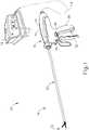
- FIG. 1depicts an exemplary surgical system (10) including a generator (12) and a surgical instrument (14).
- Surgical instrument (14)is operatively coupled with the generator (12) via power cable (16).
- generator (12)is operable to power surgical instrument (14) to deliver ultrasonic energy for cutting tissue, and electrosurgical bipolar RF energy (i.e., therapeutic levels of RF energy) for sealing tissue.
- generator (12)is configured to power surgical instrument (14) to deliver ultrasonic energy and electrosurgical bipolar RF energy simultaneously.
- Surgical instrument (14) of the present examplecomprises a handle assembly (18), a shaft assembly (20) extending distally from the handle assembly (18), and an end effector (22) arranged at a distal end of the shaft assembly (20).
- Handle assembly (18)comprises a body (24) including a pistol grip (26) and energy control buttons (28, 30) configured to be manipulated by a surgeon.
- a trigger (32)is coupled to a lower portion of body (24) and is pivotable toward and away from pistol grip (26) to selectively actuate end effector (22), as described in greater detail below.
- handle assembly (18)may comprise a scissor grip configuration, for example.
- an ultrasonic transducer (34)is housed internally within and supported by body (24). In other configurations, ultrasonic transducer (34) may be provided externally of body (24).
- end effector (22)includes an ultrasonic blade (36) and a clamp arm (38) configured to selectively pivot toward and away from ultrasonic blade (36), for clamping tissue therebetween.
- Ultrasonic blade (36)is acoustically coupled with ultrasonic transducer (34), which is configured to drive (i.e., vibrate) ultrasonic blade (36) at ultrasonic frequencies for cutting and/or sealing tissue positioned in contact with ultrasonic blade (36).
- Clamp arm (38)is operatively coupled with trigger (32) such that clamp arm (38) is configured to pivot toward ultrasonic blade (36), to a closed position, in response to pivoting of trigger (32) toward pistol grip (26).
- clamp arm (38)is configured to pivot away from ultrasonic blade (36), to an open position (see e.g., FIGS. 1-3 ), in response to pivoting of trigger (32) away from pistol grip (26).
- trigger (32)may be coupled with trigger (32) to pivot away from pistol grip (26).
- one or more resilient membersmay be incorporated to bias clamp arm (38) and/or trigger (32) toward the open position.
- a clamp pad (40)is secured to and extends distally along a clamping side of clamp arm (38), facing ultrasonic blade (36).
- Clamp pad (40)is configured to engage and clamp tissue against a corresponding tissue treatment portion of ultrasonic blade (36) when clamp arm (38) is actuated to its closed position.
- At least a clamping-side of clamp arm (38)provides a first electrode (42), referred to herein as clamp arm electrode (42).
- at least a clamping-side of ultrasonic blade (36)provides a second electrode (44), referred to herein as a blade electrode (44).
- electrodes (42, 44)are configured to apply electrosurgical bipolar RF energy, provided by generator (12), to tissue electrically coupled with electrodes (42, 44).
- Clamp arm electrode (42)may serve as an active electrode while blade electrode (44) serves as a return electrode, or vice-versa.
- Surgical instrument (14)may be configured to apply the electrosurgical bipolar RF energy through electrodes (42, 44) while vibrating ultrasonic blade (36) at an ultrasonic frequency, before vibrating ultrasonic blade (36) at an ultrasonic frequency, and/or after vibrating ultrasonic blade (36) at an ultrasonic frequency.
- shaft assembly (20)extends along a longitudinal axis and includes an outer tube (46), an inner tube (48) received within outer tube (46), and an ultrasonic waveguide (50) supported within inner tube (48).
- clamp arm (38)is coupled to distal ends of inner and outer tubes (46, 48).
- clamp arm (38)includes a pair of proximally extending clevis arms (52) that receive therebetween and pivotably couple to a distal end (54) of inner tube (48) with a pivot pin (56) received within through bores formed in clevis arms (52) and distal end (54) of inner tube (48).
- First and second clevis fingers (58)depend downwardly from clevis arms (52) and pivotably couple to a distal end (60) of outer tube (46).
- each clevis finger (58)includes a protrusion (62) that is rotatably received within a corresponding opening (64) formed in a sidewall of distal end (60) of outer tube (46).
- inner tube (48)is longitudinally fixed relative to handle assembly (18), and outer tube (46) is configured to translate relative to inner tube (48) and handle assembly (18), along the longitudinal axis of shaft assembly (20).
- clamp arm (38)pivots about pivot pin (56) toward its open position.
- clamp arm (38)pivots in an opposite direction toward its closed position.
- a proximal end of outer tube (46)is operatively coupled with trigger (32), for example via a linkage assembly, such that actuation of trigger (32) causes translation of outer tube (46) relative to inner tube (48), thereby opening or closing clamp arm (38).
- outer tube (46)may be longitudinally fixed and inner tube (48) may be configured to translate for moving clamp arm (38) between its open and closed positions.
- Shaft assembly (20) and end effector (22)are configured to rotate together about the longitudinal axis, relative to handle assembly (18).
- a retaining pin (66), shown in FIG. 4extends transversely through proximal portions of outer tube (46), inner tube (48), and waveguide (50) to thereby couple these components rotationally relative to one another.
- a rotation knob (68)is provided at a proximal end portion of shaft assembly (20) to facilitate rotation of shaft assembly (20), and end effector (22), relative to handle assembly (18).
- Rotation knob (68)is secured rotationally to shaft assembly (20) with retaining pin (66), which extends through a proximal collar of rotation knob (68). It will be appreciated that in other suitable configurations, rotation knob (68) may be omitted or substituted with alternative rotational actuation structures.
- Ultrasonic waveguide (50)is acoustically coupled at its proximal end with ultrasonic transducer (34), for example by a threaded connection, and at its distal end with ultrasonic blade (36), as shown in FIG. 5 .
- Ultrasonic blade (36)is shown formed integrally with waveguide (50) such that blade (36) extends distally, directly from the distal end of waveguide (50). In this manner, waveguide (50) acoustically couples ultrasonic transducer (34) with ultrasonic blade (36), and functions to communicate ultrasonic mechanical vibrations from transducer (34) to blade (36).
- ultrasonic transducer (34), waveguide (50), and ultrasonic blade (36)together define acoustic assembly (100).
- ultrasonic blade (36)may be positioned in direct contact with tissue, with or without assistive clamping force provided by clamp arm (38), to impart ultrasonic vibrational energy to the tissue and thereby cut and/or seal the tissue.
- blade (36)may cut through tissue clamped between clamp arm (38) and a first treatment side of blade (36), or blade (36) may cut through tissue positioned in contact with an oppositely disposed second treatment side of blade (36), for example during a "back-cutting" movement.
- waveguide (50)may amplify the ultrasonic vibrations delivered to blade (36).
- waveguide (50)may include various features operable to control the gain of the vibrations, and/or features suitable to tune waveguide (50) to a selected resonant frequency. Additional exemplary features of ultrasonic blade (36) and waveguide (50) are described in greater detail below.
- Waveguide (50)is supported within inner tube (48) by a plurality of nodal support elements (70) positioned along a length of waveguide (50), as shown in FIGS. 4 and 5 .
- nodal support elements (70)are positioned longitudinally along waveguide (50) at locations corresponding to acoustic nodes defined by the resonant ultrasonic vibrations communicated through waveguide (50).
- Nodal support elements (70)may provide structural support to waveguide (50), and acoustic isolation between waveguide (50) and inner and outer tubes (46, 48) of shaft assembly (20).
- nodal support elements (70)may comprise o-rings.
- Waveguide (50)is supported at its distal-most acoustic node by a nodal support element in the form of an overmold member (72), shown in FIG. 5 and described in greater detail below with reference to FIG. 7 .
- Waveguide (50)is secured longitudinally and rotationally within shaft assembly (20) by retaining pin (66), which passes through a transverse through-bore (74) formed at a proximally arranged acoustic node of waveguide (50), such as the proximal-most acoustic node, for example.
- a distal tip (76) of ultrasonic blade (36)is located at a position corresponding to an anti-node associated with the resonant ultrasonic vibrations communicated through waveguide (50).
- waveguide (50)Such a configuration enables the acoustic assembly (100) of instrument (14) to be tuned to a preferred resonant frequency f o when ultrasonic blade (36) is not loaded by tissue.
- ultrasonic transducer (34)When ultrasonic transducer (34) is energized by generator (12) to transmit mechanical vibrations through waveguide (50) to blade (36), distal tip (76) of blade (36) is caused to oscillate longitudinally in the range of approximately 20 to 120 microns peak-to-peak, for example, and in some instances in the range of approximately 20 to 50 microns, at a predetermined vibratory frequency fo of approximately 50 kHz, for example.
- the ultrasonic oscillation of blade (36)may simultaneously sever the tissue and denature the proteins in adjacent tissue cells, thereby providing a coagulative effect with minimal thermal spread.
- distal end (54) of inner tube (48)may be offset radially outwardly relative to a remaining proximal portion of inner tube (48).
- This configurationenables pivot pin bore (78), which receives clamp arm pivot pin (56), to be spaced further away from the longitudinal axis of shaft assembly (20) than if distal end (54) where formed flush with the remaining proximal portion of inner tube (48).
- thisprovides increased clearance between proximal portions of clamp arm electrode (42) and blade electrode (44), thereby mitigating risk of undesired "shorting" between electrodes (42, 44) and their corresponding active and return electrical paths, for example during back-cutting when ultrasonic blade (36) flexes toward clamp arm (38) and pivot pin (56) in response to normal force exerted on blade (36) by tissue.
- ultrasonic blade (36)may tend to deflect slightly away from the longitudinal axis of shaft assembly (20), toward pin (56).
- distal end (54)provides additional lateral clearance between pivot pin (56) and ultrasonic blade (36), thereby reducing or eliminating the risk of contact between ultrasonic blade (36) and pivot pin (56) when ultrasonic blade (36) deflects laterally during back-cutting operations.
- the additional clearanceprevents mechanical damage that might otherwise result from contact between ultrasonic blade (36) and pivot pin (56) when ultrasonic blade (36) is vibrating ultrasonically.
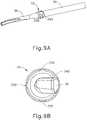
- FIGS. 7-9Bshow additional details of overmold member (72).
- overmold member (72)encircles waveguide (50) at a distal-most acoustic node thereof, thereby supporting waveguide (50) within inner tube (48) and defining a distal-most waveguide support location.
- waveguide (50)includes an annular nodal flange (51) at its distal-most acoustic node, and overmold member (72) encircles nodal flange (51).
- Ultrasonic blade (36)is integrally joined to waveguide (50) at distal nodal flange (51) and extends distally therefrom.
- overmold member (72)includes a load bearing portion (330) and an integrally formed sealing portion (332) extending proximally from load bearing portion (330).
- each of load bearing support portion (330) and sealing portion (332)is configured to engage an inner surface of inner tube (48).
- Load bearing support portion (330)includes an inner annular groove (334) configured to receive distal nodal flange (51) of waveguide (50) in sealing engagement, such that load bearing support portion (330) aligns with and encircles distal nodal flange (51) while sealing portion (332) extends proximally of distal nodal flange (51).
- Load bearing support portion (330) of overmold member (72)includes a plurality of deforming elements (336) spaced circumferentially about its exterior.
- Deforming elements (336)define a maximum outer diameter of load bearing portion (330) that is greater than an inner diameter of inner tube (48). Accordingly, deforming elements (336) are configured to resiliently deform against the inner surface of inner tube (48) so as to engage inner tube (48) with an interference fit. Circumferential spacing between deforming elements (336) enables elements (336) to deform in a circumferential direction along the inner surface of inner tube (48).
- load bearing support portion (330)is configured to support waveguide (50) in coaxial alignment with the longitudinal axis of shaft assembly (20), and mitigate radial displacement of distal nodal flange (51) relative to the longitudinal axis when waveguide (50) is driven with ultrasonic energy, as described above.
- thisprevents unwanted direct contact between ultrasonic blade (36) and clamp arm (38), or clamp arm pivot pin (56), which could otherwise cause mechanical failure of blade (36) and/or electrical shorting of an RF electrical circuit of surgical instrument (10).
- Overmold member (72)may be formed of any material or combination of materials suitable to acoustically isolate distal nodal flange (51) relative to inner tube (48).
- at least deforming elements (336) and sealing portion (332)may be formed of a resiliently deformable polymeric material, such as silicone, for example.
- Each deforming element (336)is shown in the form of a rounded protrusion, or bump, integrally formed with load bearing support portion (330) and projecting radially outwardly from an outer surface thereof, and extending axially.
- load bearing support portion (330)includes four deforming elements (336) arranged with uniform circumferential spacing. In other configurations, any suitable quantity and circumferential spacing of deforming elements (336) may be provided. As shown in FIG. 7 , a distal end of load bearing support portion (330) may taper from deforming elements (336) toward ultrasonic blade (36).
- Sealing portion (332) of overmold member (72)is spaced proximally from load bearing support portion (330) by an outer annular groove (338).
- Sealing portion (332)includes an annular outer sealing edge (340) configured as a wiper seal that resiliently deforms against, and thereby establishes a liquid-tight seal with, a full inner circumference of the inner surface of inner tube (48).
- an axial dimension of sealing edge (340)is substantially less than an axial dimension of deforming elements (336).
- sealing edge (340)is configured to maintain a liquid-tight seal against inner tube (48) to prevent proximal ingress of body fluids and tissue into shaft assembly (20) along waveguide (50). Such ingress could yield undesirable reduction of ultrasonic energy delivery from waveguide (50) to ultrasonic blade (36), and/or electrical coupling of waveguide (50) to inner tube (48), which could result in shorting of the RF electrical circuit of surgical instrument (10).
- outer sealing edge (340)defines a maximum outer diameter of sealing portion (332), which may be equal to, slightly less than, or slightly greater than the maximum outer diameter of load bearing portion (330) defined by deforming elements (336).
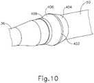
- FIG. 10shows another exemplary overmold member (400) suitable for use with surgical instrument (10) in place of overmold member (72).
- Overmold member (400)is similar to overmold member (72) described above except as otherwise described below. Similar to overmold member (72), overmold member (400) encircles nodal flange (51) at the distal-most acoustic node of waveguide (50) to thereby support waveguide (50) coaxially within inner tube (48).
- an exterior of overmold member (400)includes an annular rim (402) that engages an inner surface of inner tube (48) with an interference fit so as to function as both a load bearing portion and a sealing portion, similar to load bearing portion (330) and sealing portion (332) of overmold member (72) described above.
- Annular rim (402) of overmold member (400) of the present exampleis positioned at a medial portion of overmold member (400) such that annular rim (402) is aligned with distal nodal flange (51) of waveguide (50).
- Annular rim (402)extends continuously about a full circumference of overmold member (400) such that rim (402) is configured to establish a continuous seal with the inner surface of inner tube (48).
- annular rim (402)extends radially outwardly to define a maximum outer diameter of overmold member (400) that provides a degree of interference with inner tube (48) sufficient to provide both mechanical support and annular sealing about the full circumference of waveguide (50).
- annular rim (402)may provide a higher degree of interference with inner tube (48) than deforming elements (336) of overmold member (72).
- at least annular rim (402) of overmold member (400)may be formed of a resiliently deformable polymeric material, such as silicone, for example.
- overmold member (400)may include one or more additional annular features arranged proximally or distally of annular rim (402) and configured to sealingly engage the inner surface of inner tube (48), for instance similar to annular sealing edge (340) described above.
- Overmold member (400) of the present examplefurther includes a proximal tapered portion (404) that extends proximally from annular rim (402), a distal tapered portion (406) that extends distally from annular rim (402), and a distal flap (408) that extends distally from a distal end of distal tapered portion (406).
- Proximal tapered portion (404)tapers inwardly from annular rim (402) in a proximal direction
- distal tapered portion (406)tapers inwardly from annular rim (402) in a distal direction.
- Proximal and distal tapered portions (404, 406)may be formed with similar axial lengths and taper angles and are configured to facilitate axial assembly of inner tube (48) over waveguide (50) and overmold member (400).
- Distal flap (408)overlaps a proximal end of ultrasonic blade (36) and is configured to create an annular seal between overmold member (400) and the corresponding portion of waveguide (50) and ultrasonic blade (36) covered by distal flap (408).
- overmold member (72, 400)may be employed that incorporate one or more features from each of the overmold members (72, 400) to provide annular sealing and mechanical support about the circumference of waveguide (50) within inner tube (48).
- a surgical instrumentcomprising: (a) an ultrasonic transducer; (b) a shaft extending distally relative to the ultrasonic transducer along a longitudinal shaft axis; (c) a waveguide acoustically coupled with the ultrasonic transducer and extending distally through the shaft; (d) an end effector arranged at a distal end of the shaft, wherein the end effector includes an ultrasonic blade acoustically coupled with the waveguide, wherein the ultrasonic transducer is operable to drive the waveguide and the ultrasonic blade with ultrasonic energy; and (e) a nodal support element arranged within a distal portion of the shaft, wherein the nodal support element encircles the waveguide at a distal-most acoustic node thereof, wherein the nodal support element comprises: (i) a support portion aligned with the distal-most acoustic node, wherein the support portion is configured to engage an inner surface of the shaft and
- the support portionhas a maximum outer diameter that is greater than an inner diameter of the shaft, wherein the support portion is configured to engage the inner surface of the shaft with an interference fit.
- the support portionincludes a plurality of deformable elements spaced circumferentially about an exterior thereof, wherein the deformable elements are configured to deform against the inner surface of the shaft.
- sealing portionincludes an annular sealing edge configured to sealingly engage the inner surface of the shaft.
- the waveguideincludes a nodal flange at the distal-most acoustic node, wherein the ultrasonic blade integrally joins with the waveguide at the nodal flange, wherein an interior of the support portion includes an annular groove configured to receive the nodal flange.
- the shaftcomprises an inner tube and an outer tube, wherein the nodal support element engages an inner surface of the inner tube.
- the end effectorfurther comprises an RF electrode, wherein the RF electrode is operable to seal tissue with RF energy.
- the end effectorfurther comprises a clamp arm movable relative to the ultrasonic blade to clamp tissue therebetween, wherein the clamp arm provides a first RF electrode, wherein the ultrasonic blade provides a second RF electrode, wherein the first and second RF electrodes are operable to seal tissue with bipolar RF energy.
- a surgical instrumentcomprising: (a) an ultrasonic transducer; (b) a shaft extending distally relative to the ultrasonic transducer along a longitudinal shaft axis; (c) a waveguide acoustically coupled with the ultrasonic transducer and extending distally through the shaft; (d) an end effector arranged at a distal end of the shaft, wherein the end effector includes an ultrasonic blade acoustically coupled with the waveguide, wherein the ultrasonic transducer is operable to drive the waveguide and the ultrasonic blade with ultrasonic energy; and (e) a nodal support element positioned to support a nodal portion of the waveguide within the shaft, wherein the nodal support element includes a plurality of deformable elements configured to deform against an inner surface of the shaft.
- Example 16The surgical instrument of Example 16, wherein the nodal support element encircles a distal-most acoustic node of the waveguide.
- nodal support elementfurther comprises an annular sealing edge spaced axially from the deformable elements, wherein the annular sealing edge is configured to sealingly engage the inner surface of the shaft to prevent proximal ingress of fluid through the shaft.
- a surgical instrumentcomprising: (a) an ultrasonic transducer; (b) a shaft extending distally relative to the ultrasonic transducer along a longitudinal shaft axis; (c) a waveguide acoustically coupled with the ultrasonic transducer and extending distally through the shaft, wherein the waveguide includes a distal nodal flange; (d) an end effector arranged at a distal end of the shaft, wherein the end effector includes an ultrasonic blade acoustically coupled with the waveguide, wherein the ultrasonic transducer is operable to drive the waveguide and the ultrasonic blade with ultrasonic energy; and (e) a nodal support element arranged within a distal portion of the shaft, wherein the nodal support element comprises: (i) a plurality of protrusions configured to engage an inner surface of the shaft and thereby support the waveguide within the shaft, and (ii) a wiper seal spaced axially from the protrusions,
- Example 19The surgical instrument of Example 19, wherein he nodal support element encircles the waveguide, wherein the protrusions are spaced circumferentially about an outer surface of the nodal support element.
- a surgical instrumentcomprising: (a) an ultrasonic transducer; (b) a shaft extending distally relative to the ultrasonic transducer along a longitudinal shaft axis; (c) a waveguide acoustically coupled with the ultrasonic transducer and extending distally through the shaft; (d) an end effector arranged at a distal end of the shaft, wherein the end effector includes an ultrasonic blade acoustically coupled with the waveguide, wherein the ultrasonic transducer is operable to drive the waveguide and the ultrasonic blade with ultrasonic energy; and (e) a nodal support element arranged within a distal portion of the shaft, wherein the nodal support element encircles the waveguide at a distal-most acoustic node thereof, wherein the nodal support element includes an annular rim that defines a maximum outer diameter of the nodal support element, wherein the annular rim is configured to sealingly engage an inner surface of the shaft with an
- nodal support elementis formed of a resiliently deformable material
- nodal elementfurther comprises (i) a proximal tapered portion arranged proximally of the annular rim, and (ii) a distal tapered portion arranged distally of the annular rim.
- nodal elementfurther comprises a distal flap that extends distally from the distal tapered portion.
- the waveguideincludes a nodal flange at the distal-most acoustic node, wherein the ultrasonic blade integrally joins with the waveguide at the nodal flange, wherein the nodal support element encircles the nodal flange.
- any one or more of the teachings, expressions, embodiments, examples, etc. described hereinmay be combined with any one or more of the teachings, expressions, embodiments, examples, etc. described in U.S. Pat. App. No. [Atty. Ref. END8245USNP], entitled “Combination Ultrasonic and Electrosurgical Instrument Having Electrical Circuits With Shared Return Path,” filed on even date herewith; U.S. Pat. App. No. [Atty. Ref. END8245USNP1], entitled “Combination Ultrasonic and Electrosurgical Instrument Having Slip Ring Electrical Contact Assembly,” filed on even date herewith; U.S. Pat. App. No. [Atty. Ref.
- any one or more of the teachings, expressions, embodiments, examples, etc. described hereinmay be combined with any one or more of the teachings, expressions, embodiments, examples, etc. described in U.S. Pat. App. No. [Atty. Ref. END8146USNP], entitled “Combination Ultrasonic and Electrosurgical Instrument with Clamp Arm Position Input and Method for Identifying Tissue State,” filed on even date herewith; U.S. Pat. App. No. [Atty. Ref. END8146USNP1], entitled “Combination Ultrasonic and Electrosurgical Instrument with Adjustable Energy Modalities and Method for Sealing Tissue and Inhibiting Tissue Resection,” filed on even date herewith; U.S. Pat. App. No.
- Versions of the devices described abovemay be designed to be disposed of after a single use, or they can be designed to be used multiple times. Versions may, in either or both cases, be reconditioned for reuse after at least one use. Reconditioning may include any combination of the steps of disassembly of the device, followed by cleaning or replacement of particular pieces, and subsequent reassembly. In particular, some versions of the device may be disassembled, and any number of the particular pieces or parts of the device may be selectively replaced or removed in any combination. Upon cleaning and/or replacement of particular parts, some versions of the device may be reassembled for subsequent use either at a reconditioning facility, or by a user immediately prior to a procedure.
- reconditioning of a devicemay utilize a variety of techniques for disassembly, cleaning/replacement, and reassembly. Use of such techniques, and the resulting reconditioned device, are all within the scope of the present application.
- versions described hereinmay be sterilized before and/or after a procedure.
- the deviceis placed in a closed and sealed container, such as a plastic or TYVEK bag.
- the container and devicemay then be placed in a field of radiation that can penetrate the container, such as gamma radiation, x-rays, or high-energy electrons.
- the radiationmay kill bacteria on the device and in the container.
- the sterilized devicemay then be stored in the sterile container for later use.
- a devicemay also be sterilized using any other technique known in the art, including but not limited to beta or gamma radiation, ethylene oxide, or steam.
Landscapes
- Health & Medical Sciences (AREA)
- Surgery (AREA)
- Life Sciences & Earth Sciences (AREA)
- Engineering & Computer Science (AREA)
- Heart & Thoracic Surgery (AREA)
- Veterinary Medicine (AREA)
- Nuclear Medicine, Radiotherapy & Molecular Imaging (AREA)
- Biomedical Technology (AREA)
- Public Health (AREA)
- Medical Informatics (AREA)
- Molecular Biology (AREA)
- Animal Behavior & Ethology (AREA)
- General Health & Medical Sciences (AREA)
- Otolaryngology (AREA)
- Physics & Mathematics (AREA)
- Plasma & Fusion (AREA)
- Dentistry (AREA)
- Mechanical Engineering (AREA)
- Surgical Instruments (AREA)
Abstract
Description
- This application claims the benefit of
U.S. Provisional App. No. 62/509,351, entitled "Ultrasonic Instrument With Electrosurgical Features," filed May 22, 2017 - Ultrasonic surgical instruments utilize ultrasonic energy for both precise cutting and controlled coagulation of tissue. The ultrasonic energy cuts and coagulates by vibrating a blade in contact with the tissue. Vibrating at frequencies of approximately 50 kilohertz (kHz), for example, the ultrasonic blade denatures protein in the tissue to form a sticky coagulum. Pressure exerted on the tissue with the blade surface collapses blood vessels and allows the coagulum to form a hemostatic seal. The precision of cutting and coagulation may be controlled by the surgeon's technique and adjusting the power level, blade edge, tissue traction, and blade pressure, for example.
- Examples of ultrasonic surgical devices include the HARMONIC ACE® Ultrasonic Shears, the HARMONIC WAVE® Ultrasonic Shears, the HARMONIC FOCUS® Ultrasonic Shears, and the HARMONIC SYNERGY® Ultrasonic Blades, all by Ethicon Endo-Surgery, Inc. of Cincinnati, Ohio. Further examples of such devices and related concepts are disclosed in
U.S. Pat. No. 5,322,055, entitled "Clamp Coagulator/Cutting System for Ultrasonic Surgical Instruments," issued Jun. 21, 1994 , the disclosure of which is incorporated by reference herein;U.S. Pat. No. 5,873,873, entitled "Ultrasonic Clamp Coagulator Apparatus Having Improved Clamp Mechanism," issued Feb. 23, 1999 , the disclosure of which is incorporated by reference herein;U.S. Pat. No. 5,980,510, entitled "Ultrasonic Clamp Coagulator Apparatus Having Improved Clamp Arm Pivot Mount," issued Nov. 9, 1999 , the disclosure of which is incorporated by reference herein;U.S. Pat. No. 6,283,981, entitled "Method of Balancing Asymmetric Ultrasonic Surgical Blades," issued Sep. 4, 2001 , the disclosure of which is incorporated by reference herein;U.S. Pat. No. 6,309,400, entitled "Curved Ultrasonic Blade having a Trapezoidal Cross Section," issued Oct. 30, 2001 , the disclosure of which is incorporated by reference herein;U.S. Pat. No. 6,325,811, entitled "Blades with Functional Balance Asymmetries for use with Ultrasonic Surgical Instruments," issued Dec. 4, 2001 , the disclosure of which is incorporated by reference herein;U.S. Pat. No. 6,423,082, entitled "Ultrasonic Surgical Blade with Improved Cutting and Coagulation Features," issued Jul. 23, 2002 , the disclosure of which is incorporated by reference herein;U.S. Pat. No. 6,773,444, entitled "Blades with Functional Balance Asymmetries for Use with Ultrasonic Surgical Instruments," issued Aug. 10, 2004 , the disclosure of which is incorporated by reference herein;U.S. Pat. No. 6,783,524, entitled "Robotic Surgical Tool with Ultrasound Cauterizing and Cutting Instrument," issued Aug. 31, 2004 , the disclosure of which is incorporated by reference herein;U.S. Pat. No. 8,057,498, entitled "Ultrasonic Surgical Instrument Blades," issued Nov. 15, 2011 , the disclosure of which is incorporated by reference herein;U.S. Pat. No. 8,461,744, entitled "Rotating Transducer Mount for Ultrasonic Surgical Instruments," issued Jun. 11, 2013 , the disclosure of which is incorporated by reference herein;U.S. Pat. No. 8,591,536, entitled "Ultrasonic Surgical Instrument Blades," issued Nov. 26, 2013 , the disclosure of which is incorporated by reference herein;U.S. Pat. No. 8,623,027, entitled "Ergonomic Surgical Instruments," issued Jan. 7, 2014 , the disclosure of which is incorporated by reference herein;U.S. Pat. No. 9,095,367, entitled "Flexible Harmonic Waveguides/Blades for Surgical Instruments," issued Aug. 4, 2015 U.S. Pub. No. 2016/0022305, entitled "Ultrasonic Blade Overmold," published Jan. 28, 2016 , the disclosure of which is incorporated by reference herein. - Electrosurgical instruments utilize electrical energy for sealing tissue, and generally include a distally mounted end effector that can be configured for bipolar or monopolar operation. During bipolar operation, electrical current is provided through the tissue by active and return electrodes of the end effector. During monopolar operation, current is provided through the tissue by an active electrode of the end effector and a return electrode (e.g., a grounding pad) separately located on a patient's body. Heat generated by the current flowing through the tissue may form hemostatic seals within the tissue and/or between tissues, and thus may be particularly useful for sealing blood vessels, for example. The end effector of an electrosurgical device may also include a cutting member that is movable relative to the tissue and the electrodes to transect the tissue.
- Electrical energy applied by an electrosurgical device can be transmitted to the instrument by a generator coupled with the instrument. The electrical energy may be in the form of radio frequency ("RF") energy, which is a form of electrical energy generally in the frequency range of approximately 300 kilohertz (kHz) to 1 megahertz (MHz). In use, an electrosurgical device can transmit lower frequency RF energy through tissue, which causes ionic agitation, or friction, in effect resistive heating, thereby increasing the temperature of the tissue. Because a sharp boundary is created between the affected tissue and the surrounding tissue, surgeons can operate with a high level of precision and control, without sacrificing un-targeted adjacent tissue. The low operating temperatures of RF energy may be useful for removing, shrinking, or sculpting soft tissue while simultaneously sealing blood vessels. RF energy works particularly well on connective tissue, which is primarily comprised of collagen and shrinks when contacted by heat.
- An example of an RF electrosurgical device is the ENSEAL® Tissue Sealing Device by Ethicon Endo-Surgery, Inc., of Cincinnati, Ohio. Further examples of electrosurgical devices and related concepts are disclosed in
U.S. Pat. No. 6,500,176 entitled "Electrosurgical Systems and Techniques for Sealing Tissue," issued Dec. 31, 2002 , the disclosure of which is incorporated by reference herein;U.S. Pat. No. 7,112,201 entitled "Electrosurgical Instrument and Method of Use," issued Sep. 26, 2006 , the disclosure of which is incorporated by reference herein;U.S. Pat. No. 7,125,409, entitled "Electrosurgical Working End for Controlled Energy Delivery," issued Oct. 24, 2006 , the disclosure of which is incorporated by reference herein;U.S. Pat. No. 7,169,146 entitled "Electrosurgical Probe and Method of Use," issued Jan. 30, 2007 , the disclosure of which is incorporated by reference herein;U.S. Pat. No. 7,186,253, entitled "Electrosurgical Jaw Structure for Controlled Energy Delivery," issued Mar. 6, 2007 , the disclosure of which is incorporated by reference herein;U.S. Pat. No. 7,189,233, entitled "Electrosurgical Instrument," issued Mar. 13, 2007 , the disclosure of which is incorporated by reference herein;U.S. Pat. No. 7,220,951, entitled "Surgical Sealing Surfaces and Methods of Use," issued May 22, 2007 , the disclosure of which is incorporated by reference herein;U.S. Pat. No. 7,309,849, entitled "Polymer Compositions Exhibiting a PTC Property and Methods of Fabrication," issued Dec. 18, 2007 , the disclosure of which is incorporated by reference herein;U.S. Pat. No. 7,311,709, entitled "Electrosurgical Instrument and Method of Use," issued Dec. 25, 2007 , the disclosure of which is incorporated by reference herein;U.S. Pat. No. 7,354,440, entitled "Electrosurgical Instrument and Method of Use," issued Apr. 8, 2008 , the disclosure of which is incorporated by reference herein;U.S. Pat. No. 7,381,209, entitled "Electrosurgical Instrument," issued Jun. 3, 2008 , the disclosure of which is incorporated by reference herein. - Additional examples of electrosurgical devices and related concepts are disclosed in
U.S. Pat. No. 8,939,974, entitled "Surgical Instrument Comprising First and Second Drive Systems Actuatable by a Common Trigger Mechanism," issued Jan. 27, 2015 , the disclosure of which is incorporated by reference herein;U.S. Pat. No. 9,161,803, entitled "Motor Driven Electrosurgical Device with Mechanical and Electrical Feedback," issued Oct. 20, 2015 U.S. Pub. No. 2012/0078243, entitled "Control Features for Articulating Surgical Device," published Mar. 29, 2012 , the disclosure of which is incorporated by reference herein;U.S. Pat. No. 9,402,682, entitled "Articulation Joint Features for Articulating Surgical Device," issued Aug. 2, 2016 U.S. Pat. No. 9,089,327, entitled "Surgical Instrument with Multi-Phase Trigger Bias," issued July 28, 2015 U.S. Pat. No. 9,545,253, entitled "Surgical Instrument with Contained Dual Helix Actuator Assembly," issued Jan. 17, 2017 U.S. Pat. No. 9,572,622, entitled "Bipolar Electrosurgical Features for Targeted Hemostasis," issued Feb. 21, 2017 - Some instruments may provide ultrasonic and RF energy treatment capabilities through a single surgical device. Examples of such devices and related methods and concepts are disclosed in
U.S. Pat. No. 8,663,220, entitled "Ultrasonic Surgical Instruments," issued March 4, 2014 , the disclosure of which is incorporated by reference herein;U.S. Pub. No. 2015/0141981, entitled "Ultrasonic Surgical Instrument with Electrosurgical Feature," published May 21, 2015 , the disclosure of which is incorporated by reference herein; andU.S. Pub. No. 2017/0000541, entitled "Surgical Instrument with User Adaptable Techniques," published Jan. 5, 2017 , the disclosure of which is incorporated by reference herein. - While various types of ultrasonic surgical instruments and electrosurgical instruments, including combination ultrasonic-electrosurgical instruments, have been made and used, it is believed that no one prior to the inventor(s) has made or used the invention described in the appended claims.
- The accompanying drawings, which are incorporated in and constitute a part of this specification, illustrate embodiments of the invention, and, together with the general description of the invention given above, and the detailed description of the embodiments given below, serve to explain the principles of the present invention.
FIG. 1 depicts a perspective view of an exemplary surgical system having a generator and a surgical instrument operable to treat tissue with ultrasonic energy and bipolar RF energy;FIG. 2 depicts a top perspective view of an end effector of the surgical instrument ofFIG. 1 , having a clamp arm that provides a first electrode and an ultrasonic blade that provides a second electrode;FIG. 3 depicts a bottom perspective view of the end effector ofFIG. 2 ;FIG. 4 depicts a partially exploded perspective view of the surgical instrument ofFIG. 1 ;FIG. 5 depicts an enlarged exploded perspective view of a distal portion of the shaft assembly and the end effector of the surgical instrument ofFIG. 1 ;FIG. 6 depicts a side elevational view of a distal portion of an inner tube of the shaft assembly of the surgical instrument ofFIG. 1 ;FIG. 7 depicts a perspective view of an exemplary nodal support element of the surgical instrument ofFIG. 1 , the nodal support element configured to support a waveguide of the surgical instrument at a distal-most acoustic node thereof;FIG. 8 depicts a side sectional view of the end effector and distal portion of the shaft assembly of the surgical instrument ofFIG. 1 , showing engagement of the nodal support element ofFIG. 7 with the waveguide and inner tube of the shaft assembly;FIG. 9A depicts a perspective view of the nodal support element ofFIG. 7 mounted on a distal portion of the waveguide of the surgical instrument ofFIG. 1 , proximally of the ultrasonic blade;FIG. 9B depicts an end view of the nodal support element and the ultrasonic blade ofFIG. 9A ; andFIG. 10 depicts a perspective view of another exemplary nodal support element suitable for use with the surgical instrument ofFIG. 1 .- The drawings are not intended to be limiting in any way, and it is contemplated that various embodiments of the invention may be carried out in a variety of other ways, including those not necessarily depicted in the drawings. The accompanying drawings incorporated in and forming a part of the specification illustrate several aspects of the present invention, and together with the description serve to explain the principles of the invention; it being understood, however, that this invention is not limited to the precise arrangements shown.
- The following description of certain examples of the invention should not be used to limit the scope of the present invention. Other examples, features, aspects, embodiments, and advantages of the invention will become apparent to those skilled in the art from the following description, which is by way of illustration, one of the best modes contemplated for carrying out the invention. As will be realized, the invention is capable of other different and obvious aspects, all without departing from the invention. Accordingly, the drawings and descriptions should be regarded as illustrative in nature and not restrictive.
- For clarity of disclosure, the terms "proximal" and "distal" are defined herein relative to a surgeon, or other operator, grasping a surgical instrument having a distal surgical end effector. The term "proximal" refers to the position of an element arranged closer to the surgeon, and the term "distal" refers to the position of an element arranged closer to the surgical end effector of the surgical instrument and further away from the surgeon. Moreover, to the extent that spatial terms such as "upper," "lower," "vertical," "horizontal," or the like are used herein with reference to the drawings, it will be appreciated that such terms are used for exemplary description purposes only and are not intended to be limiting or absolute. In that regard, it will be understood that surgical instruments such as those disclosed herein may be used in a variety of orientations and positions not limited to those shown and described herein.
FIG. 1 depicts an exemplary surgical system (10) including a generator (12) and a surgical instrument (14). Surgical instrument (14) is operatively coupled with the generator (12) via power cable (16). As described in greater detail below, generator (12) is operable to power surgical instrument (14) to deliver ultrasonic energy for cutting tissue, and electrosurgical bipolar RF energy (i.e., therapeutic levels of RF energy) for sealing tissue. In exemplary configurations, generator (12) is configured to power surgical instrument (14) to deliver ultrasonic energy and electrosurgical bipolar RF energy simultaneously.- Surgical instrument (14) of the present example comprises a handle assembly (18), a shaft assembly (20) extending distally from the handle assembly (18), and an end effector (22) arranged at a distal end of the shaft assembly (20). Handle assembly (18) comprises a body (24) including a pistol grip (26) and energy control buttons (28, 30) configured to be manipulated by a surgeon. A trigger (32) is coupled to a lower portion of body (24) and is pivotable toward and away from pistol grip (26) to selectively actuate end effector (22), as described in greater detail below. In other suitable variations of surgical instrument (14), handle assembly (18) may comprise a scissor grip configuration, for example. As described in greater detail below, an ultrasonic transducer (34) is housed internally within and supported by body (24). In other configurations, ultrasonic transducer (34) may be provided externally of body (24).
- As shown in
FIGS. 2 and 3 , end effector (22) includes an ultrasonic blade (36) and a clamp arm (38) configured to selectively pivot toward and away from ultrasonic blade (36), for clamping tissue therebetween. Ultrasonic blade (36) is acoustically coupled with ultrasonic transducer (34), which is configured to drive (i.e., vibrate) ultrasonic blade (36) at ultrasonic frequencies for cutting and/or sealing tissue positioned in contact with ultrasonic blade (36). Clamp arm (38) is operatively coupled with trigger (32) such that clamp arm (38) is configured to pivot toward ultrasonic blade (36), to a closed position, in response to pivoting of trigger (32) toward pistol grip (26). Further, clamp arm (38) is configured to pivot away from ultrasonic blade (36), to an open position (see e.g.,FIGS. 1-3 ), in response to pivoting of trigger (32) away from pistol grip (26). Various suitable ways in which clamp arm (38) may be coupled with trigger (32) will be apparent to those of ordinary skill in the art in view of the teachings provided herein. In some versions, one or more resilient members may be incorporated to bias clamp arm (38) and/or trigger (32) toward the open position. - A clamp pad (40) is secured to and extends distally along a clamping side of clamp arm (38), facing ultrasonic blade (36). Clamp pad (40) is configured to engage and clamp tissue against a corresponding tissue treatment portion of ultrasonic blade (36) when clamp arm (38) is actuated to its closed position. At least a clamping-side of clamp arm (38) provides a first electrode (42), referred to herein as clamp arm electrode (42). Additionally, at least a clamping-side of ultrasonic blade (36) provides a second electrode (44), referred to herein as a blade electrode (44). As described in greater detail below, electrodes (42, 44) are configured to apply electrosurgical bipolar RF energy, provided by generator (12), to tissue electrically coupled with electrodes (42, 44). Clamp arm electrode (42) may serve as an active electrode while blade electrode (44) serves as a return electrode, or vice-versa. Surgical instrument (14) may be configured to apply the electrosurgical bipolar RF energy through electrodes (42, 44) while vibrating ultrasonic blade (36) at an ultrasonic frequency, before vibrating ultrasonic blade (36) at an ultrasonic frequency, and/or after vibrating ultrasonic blade (36) at an ultrasonic frequency.
- As shown in
FIGS. 1-5 , shaft assembly (20) extends along a longitudinal axis and includes an outer tube (46), an inner tube (48) received within outer tube (46), and an ultrasonic waveguide (50) supported within inner tube (48). As seen best inFIGS. 2-5 , clamp arm (38) is coupled to distal ends of inner and outer tubes (46, 48). In particular, clamp arm (38) includes a pair of proximally extending clevis arms (52) that receive therebetween and pivotably couple to a distal end (54) of inner tube (48) with a pivot pin (56) received within through bores formed in clevis arms (52) and distal end (54) of inner tube (48). First and second clevis fingers (58) depend downwardly from clevis arms (52) and pivotably couple to a distal end (60) of outer tube (46). Specifically, each clevis finger (58) includes a protrusion (62) that is rotatably received within a corresponding opening (64) formed in a sidewall of distal end (60) of outer tube (46). - In the present example, inner tube (48) is longitudinally fixed relative to handle assembly (18), and outer tube (46) is configured to translate relative to inner tube (48) and handle assembly (18), along the longitudinal axis of shaft assembly (20). As outer tube (46) translates distally, clamp arm (38) pivots about pivot pin (56) toward its open position. As outer tube (46) translates proximally, clamp arm (38) pivots in an opposite direction toward its closed position. A proximal end of outer tube (46) is operatively coupled with trigger (32), for example via a linkage assembly, such that actuation of trigger (32) causes translation of outer tube (46) relative to inner tube (48), thereby opening or closing clamp arm (38). In other suitable configurations not shown herein, outer tube (46) may be longitudinally fixed and inner tube (48) may be configured to translate for moving clamp arm (38) between its open and closed positions.
- Shaft assembly (20) and end effector (22) are configured to rotate together about the longitudinal axis, relative to handle assembly (18). A retaining pin (66), shown in
FIG. 4 , extends transversely through proximal portions of outer tube (46), inner tube (48), and waveguide (50) to thereby couple these components rotationally relative to one another. In the present example, a rotation knob (68) is provided at a proximal end portion of shaft assembly (20) to facilitate rotation of shaft assembly (20), and end effector (22), relative to handle assembly (18). Rotation knob (68) is secured rotationally to shaft assembly (20) with retaining pin (66), which extends through a proximal collar of rotation knob (68). It will be appreciated that in other suitable configurations, rotation knob (68) may be omitted or substituted with alternative rotational actuation structures. - Ultrasonic waveguide (50) is acoustically coupled at its proximal end with ultrasonic transducer (34), for example by a threaded connection, and at its distal end with ultrasonic blade (36), as shown in
FIG. 5 . Ultrasonic blade (36) is shown formed integrally with waveguide (50) such that blade (36) extends distally, directly from the distal end of waveguide (50). In this manner, waveguide (50) acoustically couples ultrasonic transducer (34) with ultrasonic blade (36), and functions to communicate ultrasonic mechanical vibrations from transducer (34) to blade (36). Accordingly, ultrasonic transducer (34), waveguide (50), and ultrasonic blade (36) together define acoustic assembly (100). During use, ultrasonic blade (36) may be positioned in direct contact with tissue, with or without assistive clamping force provided by clamp arm (38), to impart ultrasonic vibrational energy to the tissue and thereby cut and/or seal the tissue. For example, blade (36) may cut through tissue clamped between clamp arm (38) and a first treatment side of blade (36), or blade (36) may cut through tissue positioned in contact with an oppositely disposed second treatment side of blade (36), for example during a "back-cutting" movement. In some variations, waveguide (50) may amplify the ultrasonic vibrations delivered to blade (36). Further, waveguide (50) may include various features operable to control the gain of the vibrations, and/or features suitable to tune waveguide (50) to a selected resonant frequency. Additional exemplary features of ultrasonic blade (36) and waveguide (50) are described in greater detail below. - Waveguide (50) is supported within inner tube (48) by a plurality of nodal support elements (70) positioned along a length of waveguide (50), as shown in
FIGS. 4 and5 . Specifically, nodal support elements (70) are positioned longitudinally along waveguide (50) at locations corresponding to acoustic nodes defined by the resonant ultrasonic vibrations communicated through waveguide (50). Nodal support elements (70) may provide structural support to waveguide (50), and acoustic isolation between waveguide (50) and inner and outer tubes (46, 48) of shaft assembly (20). In exemplary variations, nodal support elements (70) may comprise o-rings. Waveguide (50) is supported at its distal-most acoustic node by a nodal support element in the form of an overmold member (72), shown inFIG. 5 and described in greater detail below with reference toFIG. 7 . Waveguide (50) is secured longitudinally and rotationally within shaft assembly (20) by retaining pin (66), which passes through a transverse through-bore (74) formed at a proximally arranged acoustic node of waveguide (50), such as the proximal-most acoustic node, for example. - In the present example, a distal tip (76) of ultrasonic blade (36) is located at a position corresponding to an anti-node associated with the resonant ultrasonic vibrations communicated through waveguide (50). Such a configuration enables the acoustic assembly (100) of instrument (14) to be tuned to a preferred resonant frequency fo when ultrasonic blade (36) is not loaded by tissue. When ultrasonic transducer (34) is energized by generator (12) to transmit mechanical vibrations through waveguide (50) to blade (36), distal tip (76) of blade (36) is caused to oscillate longitudinally in the range of approximately 20 to 120 microns peak-to-peak, for example, and in some instances in the range of approximately 20 to 50 microns, at a predetermined vibratory frequency fo of approximately 50 kHz, for example. When ultrasonic blade (36) is positioned in contact with tissue, the ultrasonic oscillation of blade (36) may simultaneously sever the tissue and denature the proteins in adjacent tissue cells, thereby providing a coagulative effect with minimal thermal spread.
- As shown in
FIG. 6 , distal end (54) of inner tube (48) may be offset radially outwardly relative to a remaining proximal portion of inner tube (48). This configuration enables pivot pin bore (78), which receives clamp arm pivot pin (56), to be spaced further away from the longitudinal axis of shaft assembly (20) than if distal end (54) where formed flush with the remaining proximal portion of inner tube (48). Advantageously, this provides increased clearance between proximal portions of clamp arm electrode (42) and blade electrode (44), thereby mitigating risk of undesired "shorting" between electrodes (42, 44) and their corresponding active and return electrical paths, for example during back-cutting when ultrasonic blade (36) flexes toward clamp arm (38) and pivot pin (56) in response to normal force exerted on blade (36) by tissue. In other words, when ultrasonic blade (36) is used in a back-cutting operation, ultrasonic blade (36) may tend to deflect slightly away from the longitudinal axis of shaft assembly (20), toward pin (56). By having pivot pin bore (78) spaced further away from the longitudinal axis than pivot pin bore (78) otherwise would be in the absence of the radial offset provided by distal end (54) of the present example, distal end (54) provides additional lateral clearance between pivot pin (56) and ultrasonic blade (36), thereby reducing or eliminating the risk of contact between ultrasonic blade (36) and pivot pin (56) when ultrasonic blade (36) deflects laterally during back-cutting operations. In addition to preventing electrical short circuits that would otherwise result from contact between ultrasonic blade (36) and pivot pin (56) when end effector (22) is activated to apply RF electrosurgical energy, the additional clearance prevents mechanical damage that might otherwise result from contact between ultrasonic blade (36) and pivot pin (56) when ultrasonic blade (36) is vibrating ultrasonically. FIGS. 7-9B show additional details of overmold member (72). As described above, overmold member (72) encircles waveguide (50) at a distal-most acoustic node thereof, thereby supporting waveguide (50) within inner tube (48) and defining a distal-most waveguide support location. As shown inFIG. 8 , waveguide (50) includes an annular nodal flange (51) at its distal-most acoustic node, and overmold member (72) encircles nodal flange (51). Ultrasonic blade (36) is integrally joined to waveguide (50) at distal nodal flange (51) and extends distally therefrom.- As shown in
FIG. 7 , overmold member (72) includes a load bearing portion (330) and an integrally formed sealing portion (332) extending proximally from load bearing portion (330). As described below, each of load bearing support portion (330) and sealing portion (332) is configured to engage an inner surface of inner tube (48). Load bearing support portion (330) includes an inner annular groove (334) configured to receive distal nodal flange (51) of waveguide (50) in sealing engagement, such that load bearing support portion (330) aligns with and encircles distal nodal flange (51) while sealing portion (332) extends proximally of distal nodal flange (51). - Load bearing support portion (330) of overmold member (72) includes a plurality of deforming elements (336) spaced circumferentially about its exterior. Deforming elements (336) define a maximum outer diameter of load bearing portion (330) that is greater than an inner diameter of inner tube (48). Accordingly, deforming elements (336) are configured to resiliently deform against the inner surface of inner tube (48) so as to engage inner tube (48) with an interference fit. Circumferential spacing between deforming elements (336) enables elements (336) to deform in a circumferential direction along the inner surface of inner tube (48). In this manner, load bearing support portion (330) is configured to support waveguide (50) in coaxial alignment with the longitudinal axis of shaft assembly (20), and mitigate radial displacement of distal nodal flange (51) relative to the longitudinal axis when waveguide (50) is driven with ultrasonic energy, as described above. Advantageously, this prevents unwanted direct contact between ultrasonic blade (36) and clamp arm (38), or clamp arm pivot pin (56), which could otherwise cause mechanical failure of blade (36) and/or electrical shorting of an RF electrical circuit of surgical instrument (10). Overmold member (72) may be formed of any material or combination of materials suitable to acoustically isolate distal nodal flange (51) relative to inner tube (48). For instance, at least deforming elements (336) and sealing portion (332) may be formed of a resiliently deformable polymeric material, such as silicone, for example.
- Each deforming element (336) is shown in the form of a rounded protrusion, or bump, integrally formed with load bearing support portion (330) and projecting radially outwardly from an outer surface thereof, and extending axially. As shown in
FIGS. 7-9B , load bearing support portion (330) includes four deforming elements (336) arranged with uniform circumferential spacing. In other configurations, any suitable quantity and circumferential spacing of deforming elements (336) may be provided. As shown inFIG. 7 , a distal end of load bearing support portion (330) may taper from deforming elements (336) toward ultrasonic blade (36). - Sealing portion (332) of overmold member (72) is spaced proximally from load bearing support portion (330) by an outer annular groove (338). Sealing portion (332) includes an annular outer sealing edge (340) configured as a wiper seal that resiliently deforms against, and thereby establishes a liquid-tight seal with, a full inner circumference of the inner surface of inner tube (48). As shown, an axial dimension of sealing edge (340) is substantially less than an axial dimension of deforming elements (336). Accordingly, while deforming elements (336) are configured to provide structural support to waveguide (50), sealing edge (340) is configured to maintain a liquid-tight seal against inner tube (48) to prevent proximal ingress of body fluids and tissue into shaft assembly (20) along waveguide (50). Such ingress could yield undesirable reduction of ultrasonic energy delivery from waveguide (50) to ultrasonic blade (36), and/or electrical coupling of waveguide (50) to inner tube (48), which could result in shorting of the RF electrical circuit of surgical instrument (10). As shown in
FIGS. 8 and9B , outer sealing edge (340) defines a maximum outer diameter of sealing portion (332), which may be equal to, slightly less than, or slightly greater than the maximum outer diameter of load bearing portion (330) defined by deforming elements (336). FIG. 10 shows another exemplary overmold member (400) suitable for use with surgical instrument (10) in place of overmold member (72). Overmold member (400) is similar to overmold member (72) described above except as otherwise described below. Similar to overmold member (72), overmold member (400) encircles nodal flange (51) at the distal-most acoustic node of waveguide (50) to thereby support waveguide (50) coaxially within inner tube (48). Unlike overmold member (72), an exterior of overmold member (400) includes an annular rim (402) that engages an inner surface of inner tube (48) with an interference fit so as to function as both a load bearing portion and a sealing portion, similar to load bearing portion (330) and sealing portion (332) of overmold member (72) described above.- Annular rim (402) of overmold member (400) of the present example is positioned at a medial portion of overmold member (400) such that annular rim (402) is aligned with distal nodal flange (51) of waveguide (50). Annular rim (402) extends continuously about a full circumference of overmold member (400) such that rim (402) is configured to establish a continuous seal with the inner surface of inner tube (48). Moreover, annular rim (402) extends radially outwardly to define a maximum outer diameter of overmold member (400) that provides a degree of interference with inner tube (48) sufficient to provide both mechanical support and annular sealing about the full circumference of waveguide (50). In some examples, annular rim (402) may provide a higher degree of interference with inner tube (48) than deforming elements (336) of overmold member (72). However, similar to deforming elements (50), at least annular rim (402) of overmold member (400) may be formed of a resiliently deformable polymeric material, such as silicone, for example. Though not shown, overmold member (400) may include one or more additional annular features arranged proximally or distally of annular rim (402) and configured to sealingly engage the inner surface of inner tube (48), for instance similar to annular sealing edge (340) described above.
- Overmold member (400) of the present example further includes a proximal tapered portion (404) that extends proximally from annular rim (402), a distal tapered portion (406) that extends distally from annular rim (402), and a distal flap (408) that extends distally from a distal end of distal tapered portion (406). Proximal tapered portion (404) tapers inwardly from annular rim (402) in a proximal direction, and distal tapered portion (406) tapers inwardly from annular rim (402) in a distal direction. Proximal and distal tapered portions (404, 406) may be formed with similar axial lengths and taper angles and are configured to facilitate axial assembly of inner tube (48) over waveguide (50) and overmold member (400). Distal flap (408) overlaps a proximal end of ultrasonic blade (36) and is configured to create an annular seal between overmold member (400) and the corresponding portion of waveguide (50) and ultrasonic blade (36) covered by distal flap (408). It will be appreciated that various other versions of overmold member (72, 400) may be employed that incorporate one or more features from each of the overmold members (72, 400) to provide annular sealing and mechanical support about the circumference of waveguide (50) within inner tube (48).
- The following examples relate to various non-exhaustive ways in which the teachings herein may be combined or applied. It should be understood that the following examples are not intended to restrict the coverage of any claims that may be presented at any time in this application or in subsequent filings of this application. No disclaimer is intended. The following examples are being provided for nothing more than merely illustrative purposes. It is contemplated that the various teachings herein may be arranged and applied in numerous other ways. It is also contemplated that some variations may omit certain features referred to in the below examples. Therefore, none of the aspects or features referred to below should be deemed critical unless otherwise explicitly indicated as such at a later date by the inventors or by a successor in interest to the inventors. If any claims are presented in this application or in subsequent filings related to this application that include additional features beyond those referred to below, those additional features shall not be presumed to have been added for any reason relating to patentability.
- A surgical instrument comprising: (a) an ultrasonic transducer; (b) a shaft extending distally relative to the ultrasonic transducer along a longitudinal shaft axis; (c) a waveguide acoustically coupled with the ultrasonic transducer and extending distally through the shaft; (d) an end effector arranged at a distal end of the shaft, wherein the end effector includes an ultrasonic blade acoustically coupled with the waveguide, wherein the ultrasonic transducer is operable to drive the waveguide and the ultrasonic blade with ultrasonic energy; and (e) a nodal support element arranged within a distal portion of the shaft, wherein the nodal support element encircles the waveguide at a distal-most acoustic node thereof, wherein the nodal support element comprises: (i) a support portion aligned with the distal-most acoustic node, wherein the support portion is configured to engage an inner surface of the shaft and thereby support the waveguide in coaxial alignment with the shaft axis, and (ii) a sealing portion extending axially from the support portion, wherein the sealing portion is configured to sealingly engage the inner surface of the shaft and thereby prevent proximal ingress of fluid through the shaft.
- The surgical instrument of Example 1, wherein the nodal support element comprises an overmold member.
- The surgical instrument of any of the previous Examples, wherein the support portion has a maximum outer diameter that is greater than an inner diameter of the shaft, wherein the support portion is configured to engage the inner surface of the shaft with an interference fit.
- The surgical instrument of any of the previous Examples, wherein the support portion includes a plurality of deformable elements spaced circumferentially about an exterior thereof, wherein the deformable elements are configured to deform against the inner surface of the shaft.
- The surgical instrument of Example 4, herein the deformable elements are resiliently deformable.
- The surgical instrument of any of Examples 4 through 5, wherein the deformable elements are arranged with uniform circumferential spacing.
- The surgical instrument of any of Examples 4 through 6, wherein the plurality of deformable elements comprises at least four deformable elements.
- The surgical instrument of any of the previous Examples, wherein the sealing portion extends proximally from the support portion.
- The surgical instrument of any of the previous Examples, wherein the sealing portion includes an annular sealing edge configured to sealingly engage the inner surface of the shaft.
- The surgical instrument of any of Example 9, wherein the annular sealing edge is spaced axially from the support portion by an annular groove formed in an exterior of the nodal support element.
- The surgical instrument of any of the previous Examples, wherein the support portion has an axial length greater than an axial length of the sealing portion.
- The surgical instrument of any of the previous Examples, wherein the waveguide includes a nodal flange at the distal-most acoustic node, wherein the ultrasonic blade integrally joins with the waveguide at the nodal flange, wherein an interior of the support portion includes an annular groove configured to receive the nodal flange.
- The surgical instrument of any of the previous Examples, wherein the shaft comprises an inner tube and an outer tube, wherein the nodal support element engages an inner surface of the inner tube.
- The surgical instrument of any of the previous Examples, wherein the end effector further comprises an RF electrode, wherein the RF electrode is operable to seal tissue with RF energy.
- The surgical instrument of any of the previous Examples, wherein the end effector further comprises a clamp arm movable relative to the ultrasonic blade to clamp tissue therebetween, wherein the clamp arm provides a first RF electrode, wherein the ultrasonic blade provides a second RF electrode, wherein the first and second RF electrodes are operable to seal tissue with bipolar RF energy.
- A surgical instrument comprising: (a) an ultrasonic transducer; (b) a shaft extending distally relative to the ultrasonic transducer along a longitudinal shaft axis; (c) a waveguide acoustically coupled with the ultrasonic transducer and extending distally through the shaft; (d) an end effector arranged at a distal end of the shaft, wherein the end effector includes an ultrasonic blade acoustically coupled with the waveguide, wherein the ultrasonic transducer is operable to drive the waveguide and the ultrasonic blade with ultrasonic energy; and (e) a nodal support element positioned to support a nodal portion of the waveguide within the shaft, wherein the nodal support element includes a plurality of deformable elements configured to deform against an inner surface of the shaft.
- The surgical instrument of Example 16, wherein the nodal support element encircles a distal-most acoustic node of the waveguide.
- The surgical instrument of any of Examples 16 through 17, wherein the nodal support element further comprises an annular sealing edge spaced axially from the deformable elements, wherein the annular sealing edge is configured to sealingly engage the inner surface of the shaft to prevent proximal ingress of fluid through the shaft.
- A surgical instrument comprising: (a) an ultrasonic transducer; (b) a shaft extending distally relative to the ultrasonic transducer along a longitudinal shaft axis; (c) a waveguide acoustically coupled with the ultrasonic transducer and extending distally through the shaft, wherein the waveguide includes a distal nodal flange; (d) an end effector arranged at a distal end of the shaft, wherein the end effector includes an ultrasonic blade acoustically coupled with the waveguide, wherein the ultrasonic transducer is operable to drive the waveguide and the ultrasonic blade with ultrasonic energy; and (e) a nodal support element arranged within a distal portion of the shaft, wherein the nodal support element comprises: (i) a plurality of protrusions configured to engage an inner surface of the shaft and thereby support the waveguide within the shaft, and (ii) a wiper seal spaced axially from the protrusions, wherein the wiper seal is configured to sealingly engage the inner surface of the shaft and thereby prevent proximal ingress of fluid through the shaft.
- The surgical instrument of Example 19, wherein he nodal support element encircles the waveguide, wherein the protrusions are spaced circumferentially about an outer surface of the nodal support element.
- A surgical instrument comprising: (a) an ultrasonic transducer; (b) a shaft extending distally relative to the ultrasonic transducer along a longitudinal shaft axis; (c) a waveguide acoustically coupled with the ultrasonic transducer and extending distally through the shaft; (d) an end effector arranged at a distal end of the shaft, wherein the end effector includes an ultrasonic blade acoustically coupled with the waveguide, wherein the ultrasonic transducer is operable to drive the waveguide and the ultrasonic blade with ultrasonic energy; and (e) a nodal support element arranged within a distal portion of the shaft, wherein the nodal support element encircles the waveguide at a distal-most acoustic node thereof, wherein the nodal support element includes an annular rim that defines a maximum outer diameter of the nodal support element, wherein the annular rim is configured to sealingly engage an inner surface of the shaft with an interference fit to thereby support the waveguide in coaxial alignment with the shaft axis and prevent proximal ingress of fluid through the shaft.
- The surgical instrument of example 21, wherein the nodal support element is formed of a resiliently deformable material
- The surgical instrument of example 21, wherein the nodal element further comprises (i) a proximal tapered portion arranged proximally of the annular rim, and (ii) a distal tapered portion arranged distally of the annular rim.
- The surgical instrument of example 23, wherein the nodal element further comprises a distal flap that extends distally from the distal tapered portion.
- The surgical instrument of example 21, wherein the waveguide includes a nodal flange at the distal-most acoustic node, wherein the ultrasonic blade integrally joins with the waveguide at the nodal flange, wherein the nodal support element encircles the nodal flange.
- It should be understood that any one or more of the teachings, expressions, embodiments, examples, etc. described herein may be combined with any one or more of the other teachings, expressions, embodiments, examples, etc. that are described herein. The above-described teachings, expressions, embodiments, examples, etc. should therefore not be viewed in isolation relative to each other. Various suitable ways in which the teachings herein may be combined will be readily apparent to those of ordinary skill in the art in view of the teachings herein. Such modifications and variations are intended to be included within the scope of the claims.
- Further, any one or more of the teachings, expressions, embodiments, examples, etc. described herein may be combined with any one or more of the teachings, expressions, embodiments, examples, etc. described in U.S. Pat. App. No. [Atty. Ref. END8245USNP], entitled "Combination Ultrasonic and Electrosurgical Instrument Having Electrical Circuits With Shared Return Path," filed on even date herewith; U.S. Pat. App. No. [Atty. Ref. END8245USNP1], entitled "Combination Ultrasonic and Electrosurgical Instrument Having Slip Ring Electrical Contact Assembly," filed on even date herewith; U.S. Pat. App. No. [Atty. Ref. END8245USNP2], entitled "Combination Ultrasonic and Electrosurgical Instrument Having Electrically Insulating Features," filed on even date herewith; U.S. Pat. App. No. [Atty. Ref. END8245USNP3], entitled "Combination Ultrasonic and Electrosurgical Instrument Having Curved Ultrasonic Blade," filed on even date herewith; U.S. Pat. App. No. [Atty. Ref. END8245USNP4], entitled "Combination Ultrasonic and Electrosurgical Instrument Having Clamp Arm Electrode," filed on even date herewith; U.S. Pat. App. No. [Atty. Ref. END8245USNP6], entitled "Combination Ultrasonic and Electrosurgical System Having Generator Filter Circuitry," filed on even date herewith; and/or U.S. Pat. App. No. [Atty. Ref. END8245USNP7], entitled "Combination Ultrasonic and Electrosurgical System Having EEPROM and ASIC Components," filed on even date herewith. The disclosure of each of these applications is incorporated by reference herein.
- Further, any one or more of the teachings, expressions, embodiments, examples, etc. described herein may be combined with any one or more of the teachings, expressions, embodiments, examples, etc. described in U.S. Pat. App. No. [Atty. Ref. END8146USNP], entitled "Combination Ultrasonic and Electrosurgical Instrument with Clamp Arm Position Input and Method for Identifying Tissue State," filed on even date herewith; U.S. Pat. App. No. [Atty. Ref. END8146USNP1], entitled "Combination Ultrasonic and Electrosurgical Instrument with Adjustable Energy Modalities and Method for Sealing Tissue and Inhibiting Tissue Resection," filed on even date herewith; U.S. Pat. App. No. [Atty. Ref. END8146USNP2], entitled "Combination Ultrasonic and Electrosurgical Instrument with Adjustable Clamp Force and Related Methods," filed on even date herewith; U.S. Pat. App. No. [Atty. Ref. END8146USNP3], entitled "Combination Ultrasonic and Electrosurgical Instrument with Adjustable Energy Modalities and Method for Limiting Blade Temperature," filed on even date herewith; U.S. Pat. App. No. [Atty. Ref. END8146USNP4], entitled "Combination Ultrasonic and Electrosurgical Instrument and Method for Sealing Tissue with Various Termination Parameters," filed on even date herewith; and/or U.S. Pat. App. No. [Atty. Ref. END8146USNP5], entitled "Combination Ultrasonic and Electrosurgical Instrument and Method for Sealing Tissue in Successive Phases," filed on even date herewith. The disclosure of each of these applications is incorporated by reference herein.
- It should be appreciated that any patent, publication, or other disclosure material, in whole or in part, that is said to be incorporated by reference herein is incorporated herein only to the extent that the incorporated material does not conflict with existing definitions, statements, or other disclosure material set forth in this disclosure. As such, and to the extent necessary, the disclosure as explicitly set forth herein supersedes any conflicting material incorporated herein by reference. Any material, or portion thereof, that is said to be incorporated by reference herein, but which conflicts with existing definitions, statements, or other disclosure material set forth herein will only be incorporated to the extent that no conflict arises between that incorporated material and the existing disclosure material.
- Versions of the devices described above may have application in conventional medical treatments and procedures conducted by a medical professional, as well as application in robotic-assisted medical treatments and procedures. By way of example only, various teachings herein may be readily incorporated into a robotic surgical system such as the DAVINCI™ system by Intuitive Surgical, Inc., of Sunnyvale, California. Similarly, those of ordinary skill in the art will recognize that various teachings herein may be readily combined with various teachings of any of the following:
U.S. Pat. No. 5,792,135, entitled "Articulated Surgical Instrument For Performing Minimally Invasive Surgery With Enhanced Dexterity and Sensitivity," issued Aug. 11, 1998 , the disclosure of which is incorporated by reference herein;U.S. Pat. No. 5,817,084, entitled "Remote Center Positioning Device with Flexible Drive," issued Oct. 6, 1998 , the disclosure of which is incorporated by reference herein;U.S. Pat. No. 5,878,193, entitled "Automated Endoscope System for Optimal Positioning," issued March 2, 1999 , the disclosure of which is incorporated by reference herein;U.S. Pat. No. 6,231,565, entitled "Robotic Arm DLUS for Performing Surgical Tasks," issued May 15, 2001 , the disclosure of which is incorporated by reference herein;U.S. Pat. No. 6,783,524, entitled "Robotic Surgical Tool with Ultrasound Cauterizing and Cutting Instrument," issued Aug. 31, 2004 , the disclosure of which is incorporated by reference herein;U.S. Pat. No. 6,364,888, entitled "Alignment of Master and Slave in a Minimally Invasive Surgical Apparatus," issued April 2, 2002 , the disclosure of which is incorporated by reference herein;U.S. Pat. No. 7,524,320, entitled "Mechanical Actuator Interface System for Robotic Surgical Tools," issued April 28, 2009 , the disclosure of which is incorporated by reference herein;U.S. Pat. No. 7,691,098, entitled "Platform Link Wrist Mechanism," issued April 6, 2010 , the disclosure of which is incorporated by reference herein;U.S. Pat. No. 7,806,891, entitled "Repositioning and Reorientation of Master/Slave Relationship in Minimally Invasive Telesurgery," issued Oct. 5, 2010 , the disclosure of which is incorporated by reference herein;U.S. Pat. No. 8,844,789, entitled "Automated End Effector Component Reloading System for Use with a Robotic System," issued Sept. 30, 2014 , the disclosure of which is incorporated by reference herein;U.S. Pat. No. 8,820,605, entitled "Robotically-Controlled Surgical Instruments," issued Sept. 2, 2014 , the disclosure of which is incorporated by reference herein;U.S. Pat. No. 8,616,431, entitled "Shiftable Drive Interface for Robotically-Controlled Surgical Tool," issued Dec. 31, 2013 , the disclosure of which is incorporated by reference herein;U.S. Pat. No. 8,573,461, entitled "Surgical Stapling Instruments with Cam-Driven Staple Deployment Arrangements," issued Nov. 5, 2013 , the disclosure of which is incorporated by reference herein;U.S. Pat. No. 8,602,288, entitled "Robotically-Controlled Motorized Surgical End Effector System with Rotary Actuated Closure Systems Having Variable Actuation Speeds," issued Dec. 10, 2013 , the disclosure of which is incorporated by reference herein;U.S. Pat. No. 9,301,759, entitled "Robotically-Controlled Surgical Instrument with Selectively Articulatable End Effector," issued April 5, 2016 U.S. Pat. No. 8,783,541, entitled "Robotically-Controlled Surgical End Effector System," issued July 22, 2014 , the disclosure of which is incorporated by reference herein;U.S. Pat. No. 8,479,969, entitled "Drive Interface for Operably Coupling a Manipulatable Surgical Tool to a Robot," issued July 9, 2013 ;U.S. Pat. Pub. No. 8,800,838, entitled "Robotically-Controlled Cable-Based Surgical End Effectors," issued Aug. 12, 2014 , the disclosure of which is incorporated by reference herein; and/orU.S. Pat. No. 8,573,465, entitled "Robotically-Controlled Surgical End Effector System with Rotary Actuated Closure Systems," issued Nov. 5, 2013 , the disclosure of which is incorporated by reference herein. - Versions of the devices described above may be designed to be disposed of after a single use, or they can be designed to be used multiple times. Versions may, in either or both cases, be reconditioned for reuse after at least one use. Reconditioning may include any combination of the steps of disassembly of the device, followed by cleaning or replacement of particular pieces, and subsequent reassembly. In particular, some versions of the device may be disassembled, and any number of the particular pieces or parts of the device may be selectively replaced or removed in any combination. Upon cleaning and/or replacement of particular parts, some versions of the device may be reassembled for subsequent use either at a reconditioning facility, or by a user immediately prior to a procedure. Those skilled in the art will appreciate that reconditioning of a device may utilize a variety of techniques for disassembly, cleaning/replacement, and reassembly. Use of such techniques, and the resulting reconditioned device, are all within the scope of the present application.
- By way of example only, versions described herein may be sterilized before and/or after a procedure. In one sterilization technique, the device is placed in a closed and sealed container, such as a plastic or TYVEK bag. The container and device may then be placed in a field of radiation that can penetrate the container, such as gamma radiation, x-rays, or high-energy electrons. The radiation may kill bacteria on the device and in the container. The sterilized device may then be stored in the sterile container for later use. A device may also be sterilized using any other technique known in the art, including but not limited to beta or gamma radiation, ethylene oxide, or steam.
- Having shown and described various embodiments of the present invention, further adaptations of the methods and systems described herein may be accomplished by appropriate modifications by one of ordinary skill in the art without departing from the scope of the present invention. Several of such potential modifications have been mentioned, and others will be apparent to those skilled in the art. For instance, the examples, embodiments, geometries, materials, dimensions, ratios, steps, and the like discussed above are illustrative and are not required. Accordingly, the scope of the present invention should be considered in terms of the following claims and is understood not to be limited to the details of structure and operation shown and described in the specification and drawings.
- Embodiments of the invention:
- 1. A surgical instrument comprising:
- (a) an ultrasonic transducer;
- (b) a shaft extending distally relative to the ultrasonic transducer along a longitudinal shaft axis;
- (c) a waveguide acoustically coupled with the ultrasonic transducer and extending distally through the shaft;
- (d) an end effector arranged at a distal end of the shaft, wherein the end effector includes an ultrasonic blade acoustically coupled with the waveguide, wherein the ultrasonic transducer is operable to drive the waveguide and the ultrasonic blade with ultrasonic energy; and
- (e) a nodal support element arranged within a distal portion of the shaft, wherein the nodal support element encircles the waveguide at a distal-most acoustic node thereof, wherein the nodal support element comprises:
- (i) a support portion aligned with the distal-most acoustic node, wherein the support portion is configured to engage an inner surface of the shaft and thereby support the waveguide in coaxial alignment with the shaft axis, and
- (ii) a sealing portion extending axially from the support portion, wherein the sealing portion is configured to sealingly engage the inner surface of the shaft and thereby prevent proximal ingress of fluid through the shaft.
- 2. The surgical instrument of
embodiment 1, wherein the nodal support element comprises an overmold member. - 3. The surgical instrument of
embodiment 1, wherein the support portion has a maximum outer diameter that is greater than an inner diameter of the shaft, wherein the support portion is configured to engage the inner surface of the shaft with an interference fit. - 4. The surgical instrument of
embodiment 1, wherein the support portion includes a plurality of deformable elements spaced circumferentially about an exterior thereof, wherein the deformable elements are configured to deform against the inner surface of the shaft. - 5. The surgical instrument of embodiment 4, wherein the deformable elements are resiliently deformable.
- 6. The surgical instrument of embodiment 4, wherein the deformable elements are arranged with uniform circumferential spacing.
- 7. The surgical instrument of embodiment 4, wherein the plurality of deformable elements comprises at least four deformable elements.
- 8. The surgical instrument of
embodiment 1, wherein the sealing portion extends proximally from the support portion. - 9. The surgical instrument of
embodiment 1, wherein the sealing portion includes an annular sealing edge configured to sealingly engage the inner surface of the shaft. - 10. The surgical instrument of embodiment 9, wherein the annular sealing edge is spaced axially from the support portion by an annular groove formed in an exterior of the nodal support element.
- 11. The surgical instrument of
embodiment 1, wherein the support portion has an axial length greater than an axial length of the sealing portion. - 12. The surgical instrument of
embodiment 1, wherein the waveguide includes a nodal flange at the distal-most acoustic node, wherein the ultrasonic blade integrally joins with the waveguide at the nodal flange, wherein an interior of the support portion includes an annular groove configured to receive the nodal flange. - 13. The surgical instrument of
embodiment 1, wherein the shaft comprises an inner tube and an outer tube, wherein the nodal support element engages an inner surface of the inner tube. - 14. The surgical instrument of
embodiment 1, wherein the end effector further comprises an RF electrode, wherein the RF electrode is operable to seal tissue with RF energy. - 15. The surgical instrument of
embodiment 1, wherein the end effector further comprises a clamp arm movable relative to the ultrasonic blade to clamp tissue therebetween, wherein the clamp arm provides a first RF electrode, wherein the ultrasonic blade provides a second RF electrode, wherein the first and second RF electrodes are operable to seal tissue with bipolar RF energy. - 16. A surgical instrument comprising:
- (a) an ultrasonic transducer;
- (b) a shaft extending distally relative to the ultrasonic transducer along a longitudinal shaft axis;
- (c) a waveguide acoustically coupled with the ultrasonic transducer and extending distally through the shaft;
- (d) an end effector arranged at a distal end of the shaft, wherein the end effector includes an ultrasonic blade acoustically coupled with the waveguide, wherein the ultrasonic transducer is operable to drive the waveguide and the ultrasonic blade with ultrasonic energy; and
- (e) a nodal support element positioned to support a nodal portion of the waveguide within the shaft, wherein the nodal support element includes a plurality of deformable elements configured to deform against an inner surface of the shaft.
- 17. The surgical instrument of
embodiment 16, wherein the nodal support element encircles a distal-most acoustic node of the waveguide. - 18. The surgical instrument of cla
embodiment im 16, wherein the nodal support element further comprises an annular sealing edge spaced axially from the deformable elements, wherein the annular sealing edge is configured to sealingly engage the inner surface of the shaft to prevent proximal ingress of fluid through the shaft. - 19. A surgical instrument comprising:
- (a) an ultrasonic transducer;
- (b) a shaft extending distally relative to the ultrasonic transducer along a longitudinal shaft axis;
- (c) a waveguide acoustically coupled with the ultrasonic transducer and extending distally through the shaft, wherein the waveguide includes a distal nodal flange;
- (d) an end effector arranged at a distal end of the shaft, wherein the end effector includes an ultrasonic blade acoustically coupled with the waveguide, wherein the ultrasonic transducer is operable to drive the waveguide and the ultrasonic blade with ultrasonic energy; and
- (e) a nodal support element arranged within a distal portion of the shaft, wherein the nodal support element comprises:
- (i) a plurality of protrusions configured to engage an inner surface of the shaft and thereby support the waveguide within the shaft, and
- (ii) a wiper seal spaced axially from the protrusions, wherein the wiper seal is configured to sealingly engage the inner surface of the shaft and thereby prevent proximal ingress of fluid through the shaft.
- 20. The surgical instrument of embodiment 19, wherein the nodal support element encircles the waveguide, wherein the protrusions are spaced circumferentially about an outer surface of the nodal support element.
Claims (14)
- A surgical instrument comprising:(a) an ultrasonic transducer;(b) a shaft extending distally relative to the ultrasonic transducer along a longitudinal shaft axis;(c) a waveguide acoustically coupled with the ultrasonic transducer and extending distally through the shaft;(d) an end effector arranged at a distal end of the shaft, wherein the end effector includes an ultrasonic blade acoustically coupled with the waveguide, wherein the ultrasonic transducer is operable to drive the waveguide and the ultrasonic blade with ultrasonic energy; and(e) a nodal support element positioned to support a nodal portion of the waveguide within the shaft, wherein the nodal support element includes a plurality of deformable elements configured to deform against an inner surface of the shaft.
- The surgical instrument of claim 1, wherein the nodal support element encircles a distal-most acoustic node of the waveguide.
- The surgical instrument of claim 1, wherein the nodal support element further comprises an annular sealing edge spaced axially from the deformable elements, wherein the annular sealing edge is configured to sealingly engage the inner surface of the shaft to prevent proximal ingress of fluid through the shaft.
- The surgical instrument of claim 1, wherein the nodal support element comprises an overmold member.
- The surgical instrument of claim 1, wherein the nodal support element has a maximum outer diameter that is greater than an inner diameter of the shaft, wherein the nodal support element is configured to engage the inner surface of the shaft with an interference fit.
- The surgical instrument of claim 1, wherein the deformable elements are resiliently deformable.
- The surgical instrument of claim 1, wherein the deformable elements are arranged with uniform circumferential spacing.
- The surgical instrument of claim 1, wherein the plurality of deformable elements comprises at least four deformable elements.
- The surgical instrument of claim 1, wherein the annular sealing edge is positioned proximally from the deformable elements.
- The surgical instrument of claim 3, wherein the annular sealing edge is spaced axially from the deformable elements by an annular groove formed in an exterior of the nodal support element.
- The surgical instrument of claim 1, wherein the waveguide includes a nodal flange at the distal-most acoustic node, wherein the ultrasonic blade integrally joins with the waveguide at the nodal flange, wherein an interior of the nodal support element includes an annular groove configured to receive the nodal flange.
- The surgical instrument of claim 1, wherein the shaft comprises an inner tube and an outer tube, wherein the nodal support element engages an inner surface of the inner tube.
- The surgical instrument of claim 1, wherein the end effector further comprises an RF electrode, wherein the RF electrode is operable to seal tissue with RF energy.
- The surgical instrument of claim 1, wherein the end effector further comprises a clamp arm movable relative to the ultrasonic blade to clamp tissue therebetween, wherein the clamp arm provides a first RF electrode, wherein the ultrasonic blade provides a second RF electrode, wherein the first and second RF electrodes are operable to seal tissue with bipolar RF energy.
Applications Claiming Priority (4)
| Application Number | Priority Date | Filing Date | Title |
|---|---|---|---|
| US201762509351P | 2017-05-22 | 2017-05-22 | |
| US15/967,759US11051866B2 (en) | 2017-05-22 | 2018-05-01 | Combination ultrasonic and electrosurgical instrument having ultrasonic waveguide with distal overmold member |
| PCT/US2018/033615WO2019013867A1 (en) | 2017-05-22 | 2018-05-21 | Combination ultrasonic and electrosurgical instrument having ultrasonic waveguide with distal overmold member |
| EP18730577.6AEP3629952B8 (en) | 2017-05-22 | 2018-05-21 | Combination ultrasonic and electrosurgical instrument having ultrasonic waveguide with distal overmold member |
Related Parent Applications (2)
| Application Number | Title | Priority Date | Filing Date |
|---|---|---|---|
| EP18730577.6ADivision-IntoEP3629952B8 (en) | 2017-05-22 | 2018-05-21 | Combination ultrasonic and electrosurgical instrument having ultrasonic waveguide with distal overmold member |
| EP18730577.6ADivisionEP3629952B8 (en) | 2017-05-22 | 2018-05-21 | Combination ultrasonic and electrosurgical instrument having ultrasonic waveguide with distal overmold member |
Publications (3)
| Publication Number | Publication Date |
|---|---|
| EP4005511A1true EP4005511A1 (en) | 2022-06-01 |
| EP4005511B1 EP4005511B1 (en) | 2024-09-25 |
| EP4005511C0 EP4005511C0 (en) | 2024-09-25 |
Family
ID=62620977
Family Applications (10)
| Application Number | Title | Priority Date | Filing Date |
|---|---|---|---|
| EP18730577.6AActiveEP3629952B8 (en) | 2017-05-22 | 2018-05-21 | Combination ultrasonic and electrosurgical instrument having ultrasonic waveguide with distal overmold member |
| EP18731603.9AActiveEP3634271B1 (en) | 2017-05-22 | 2018-05-21 | Combination ultrasonic and electrosurgical system having generator filter circuitry |
| EP18769834.5APendingEP3634273A1 (en) | 2017-05-22 | 2018-05-21 | Combination ultrasonic and electrosurgical instrument having electrically insulating features |
| EP22151018.3AActiveEP4005511B1 (en) | 2017-05-22 | 2018-05-21 | Combination ultrasonic and electrosurgical instrument having ultrasonic waveguide with distal overmold member |
| EP21172089.1AActiveEP3881782B1 (en) | 2017-05-22 | 2018-05-21 | Combination ultrasonic and electrosurgical instrument having curved ultrasonic blade |
| EP18730576.8AActiveEP3629951B1 (en) | 2017-05-22 | 2018-05-21 | Combination ultrasonic and electrosurgical instrument having electrical circuits with shared return path |
| EP18769835.2AActiveEP3634274B1 (en) | 2017-05-22 | 2018-05-21 | Combination ultrasonic and electrosurgical instrument having curved ultrasonic blade |
| EP18769833.7AActiveEP3629955B1 (en) | 2017-05-22 | 2018-05-21 | Combination ultrasonic and electrosurgical instrument having slip ring electrical contact assembly |
| EP18769836.0AActiveEP3634285B1 (en) | 2017-05-22 | 2018-05-21 | Combination ultrasonic and electrosurgical instrument having clamp arm electrode |
| EP18731604.7AActiveEP3634272B1 (en) | 2017-05-22 | 2018-05-21 | Combination ultrasonic and electrosurgical system having eeprom components |
Family Applications Before (3)
| Application Number | Title | Priority Date | Filing Date |
|---|---|---|---|
| EP18730577.6AActiveEP3629952B8 (en) | 2017-05-22 | 2018-05-21 | Combination ultrasonic and electrosurgical instrument having ultrasonic waveguide with distal overmold member |
| EP18731603.9AActiveEP3634271B1 (en) | 2017-05-22 | 2018-05-21 | Combination ultrasonic and electrosurgical system having generator filter circuitry |
| EP18769834.5APendingEP3634273A1 (en) | 2017-05-22 | 2018-05-21 | Combination ultrasonic and electrosurgical instrument having electrically insulating features |
Family Applications After (6)
| Application Number | Title | Priority Date | Filing Date |
|---|---|---|---|
| EP21172089.1AActiveEP3881782B1 (en) | 2017-05-22 | 2018-05-21 | Combination ultrasonic and electrosurgical instrument having curved ultrasonic blade |
| EP18730576.8AActiveEP3629951B1 (en) | 2017-05-22 | 2018-05-21 | Combination ultrasonic and electrosurgical instrument having electrical circuits with shared return path |
| EP18769835.2AActiveEP3634274B1 (en) | 2017-05-22 | 2018-05-21 | Combination ultrasonic and electrosurgical instrument having curved ultrasonic blade |
| EP18769833.7AActiveEP3629955B1 (en) | 2017-05-22 | 2018-05-21 | Combination ultrasonic and electrosurgical instrument having slip ring electrical contact assembly |
| EP18769836.0AActiveEP3634285B1 (en) | 2017-05-22 | 2018-05-21 | Combination ultrasonic and electrosurgical instrument having clamp arm electrode |
| EP18731604.7AActiveEP3634272B1 (en) | 2017-05-22 | 2018-05-21 | Combination ultrasonic and electrosurgical system having eeprom components |
Country Status (9)
| Country | Link |
|---|---|
| US (12) | US11058472B2 (en) |
| EP (10) | EP3629952B8 (en) |
| JP (9) | JP2020520723A (en) |
| CN (9) | CN110650696A (en) |
| BR (3) | BR112019024361A2 (en) |
| GB (2) | GB2608896B (en) |
| MX (8) | MX2019013908A (en) |
| PL (1) | PL3634274T3 (en) |
| WO (8) | WO2018217601A1 (en) |
Families Citing this family (61)
| Publication number | Priority date | Publication date | Assignee | Title |
|---|---|---|---|---|
| US11090104B2 (en) | 2009-10-09 | 2021-08-17 | Cilag Gmbh International | Surgical generator for ultrasonic and electrosurgical devices |
| US9408622B2 (en) | 2012-06-29 | 2016-08-09 | Ethicon Endo-Surgery, Llc | Surgical instruments with articulating shafts |
| US10194973B2 (en) | 2015-09-30 | 2019-02-05 | Ethicon Llc | Generator for digitally generating electrical signal waveforms for electrosurgical and ultrasonic surgical instruments |
| US11051840B2 (en) | 2016-01-15 | 2021-07-06 | Ethicon Llc | Modular battery powered handheld surgical instrument with reusable asymmetric handle housing |
| US11129670B2 (en) | 2016-01-15 | 2021-09-28 | Cilag Gmbh International | Modular battery powered handheld surgical instrument with selective application of energy based on button displacement, intensity, or local tissue characterization |
| US11229471B2 (en) | 2016-01-15 | 2022-01-25 | Cilag Gmbh International | Modular battery powered handheld surgical instrument with selective application of energy based on tissue characterization |
| US12193698B2 (en) | 2016-01-15 | 2025-01-14 | Cilag Gmbh International | Method for self-diagnosing operation of a control switch in a surgical instrument system |
| US11266430B2 (en) | 2016-11-29 | 2022-03-08 | Cilag Gmbh International | End effector control and calibration |
| US11058472B2 (en) | 2017-05-22 | 2021-07-13 | Cilag Gmbh International | Combination ultrasonic and electrosurgical instrument having clamp arm electrode |
| US11266455B2 (en) | 2017-05-22 | 2022-03-08 | Cilag Gmbh International | Combination ultrasonic and electrosurgical instrument with a production clamp force based ultrasonic seal process and related methods |
| USD882782S1 (en) | 2018-02-21 | 2020-04-28 | Ethicon Llc | Three dimensional adjunct |
| USD888951S1 (en)* | 2018-11-15 | 2020-06-30 | Ethicon Llc | Pair of bipolar electrosurgical jaws |
| USD966513S1 (en)* | 2019-01-25 | 2022-10-11 | Karl Storz Se & Co. Kg | Shaft attachable medical instrument |
| USD938588S1 (en)* | 2019-01-25 | 2021-12-14 | Karl Storz Se & Co. Kg | Shaft attachable medical instrument |
| US12351855B2 (en) | 2019-01-30 | 2025-07-08 | Arizona Board Of Regents On Behalf Of Arizona State University | Bioelectronic circuits, systems and methods for preparing and using them |
| AU2020253238B2 (en) | 2019-03-29 | 2025-03-06 | Gyrus Acmi, Inc. D/B/A Olympus Surgical Technologies America | Forceps motion transfer assembly |
| CN110151258B (en)* | 2019-05-01 | 2024-07-30 | 杭州康基医疗器械有限公司 | Support system for ultrasonic waveguide |
| CN110403672B (en)* | 2019-05-01 | 2024-04-19 | 杭州康基医疗器械有限公司 | Ultrasonic medical surgical instrument |
| CN110123416B (en)* | 2019-05-01 | 2024-05-07 | 杭州康基医疗器械有限公司 | Floating support structure of ultrasonic transducer |
| US12023085B2 (en) | 2019-08-29 | 2024-07-02 | Covidien Lp | Ultrasonic systems and methods with tissue resistance sensing |
| US11490890B2 (en) | 2019-09-16 | 2022-11-08 | Cilag Gmbh International | Compressible non-fibrous adjuncts |
| GB2594438A (en)* | 2019-12-05 | 2021-11-03 | Creo Medical Ltd | Electrosurgical instrument, generator and apparatus |
| US12343063B2 (en) | 2019-12-30 | 2025-07-01 | Cilag Gmbh International | Multi-layer clamp arm pad for enhanced versatility and performance of a surgical device |
| US12082808B2 (en) | 2019-12-30 | 2024-09-10 | Cilag Gmbh International | Surgical instrument comprising a control system responsive to software configurations |
| US12262937B2 (en) | 2019-12-30 | 2025-04-01 | Cilag Gmbh International | User interface for surgical instrument with combination energy modality end-effector |
| US12336747B2 (en) | 2019-12-30 | 2025-06-24 | Cilag Gmbh International | Method of operating a combination ultrasonic / bipolar RF surgical device with a combination energy modality end-effector |
| US11986201B2 (en) | 2019-12-30 | 2024-05-21 | Cilag Gmbh International | Method for operating a surgical instrument |
| US12114912B2 (en) | 2019-12-30 | 2024-10-15 | Cilag Gmbh International | Non-biased deflectable electrode to minimize contact between ultrasonic blade and electrode |
| US11944366B2 (en) | 2019-12-30 | 2024-04-02 | Cilag Gmbh International | Asymmetric segmented ultrasonic support pad for cooperative engagement with a movable RF electrode |
| US11937863B2 (en) | 2019-12-30 | 2024-03-26 | Cilag Gmbh International | Deflectable electrode with variable compression bias along the length of the deflectable electrode |
| US12053224B2 (en) | 2019-12-30 | 2024-08-06 | Cilag Gmbh International | Variation in electrode parameters and deflectable electrode to modify energy density and tissue interaction |
| US11786294B2 (en) | 2019-12-30 | 2023-10-17 | Cilag Gmbh International | Control program for modular combination energy device |
| US11779387B2 (en) | 2019-12-30 | 2023-10-10 | Cilag Gmbh International | Clamp arm jaw to minimize tissue sticking and improve tissue control |
| US11950797B2 (en) | 2019-12-30 | 2024-04-09 | Cilag Gmbh International | Deflectable electrode with higher distal bias relative to proximal bias |
| US11812957B2 (en) | 2019-12-30 | 2023-11-14 | Cilag Gmbh International | Surgical instrument comprising a signal interference resolution system |
| US11786291B2 (en) | 2019-12-30 | 2023-10-17 | Cilag Gmbh International | Deflectable support of RF energy electrode with respect to opposing ultrasonic blade |
| US11937866B2 (en) | 2019-12-30 | 2024-03-26 | Cilag Gmbh International | Method for an electrosurgical procedure |
| US20210196357A1 (en) | 2019-12-30 | 2021-07-01 | Ethicon Llc | Electrosurgical instrument with asynchronous energizing electrodes |
| CN113116508B (en)* | 2019-12-30 | 2023-10-20 | 北京术锐机器人股份有限公司 | Bipolar sealed surgical tool head |
| US12076006B2 (en) | 2019-12-30 | 2024-09-03 | Cilag Gmbh International | Surgical instrument comprising an orientation detection system |
| CN113116505B (en)* | 2019-12-30 | 2024-03-29 | 北京术锐机器人股份有限公司 | Monopole sealing operation tool head |
| US12023086B2 (en) | 2019-12-30 | 2024-07-02 | Cilag Gmbh International | Electrosurgical instrument for delivering blended energy modalities to tissue |
| US11523828B2 (en)* | 2020-01-28 | 2022-12-13 | Covidien Lp | Sealed reload assembly for stapling device |
| US11672590B2 (en)* | 2020-07-02 | 2023-06-13 | Covidien Lp | Slip-ring contact assembly for electrosurgical instruments |
| USD1029255S1 (en) | 2020-09-01 | 2024-05-28 | Cilag Gmbh International | Stapling cartridge assembly with a compressible adjunct |
| US20220079658A1 (en)* | 2020-09-14 | 2022-03-17 | Covidien Lp | Beveled end effector assembly |
| CN112237465A (en)* | 2020-11-04 | 2021-01-19 | 安速康医疗(苏州)有限公司 | Ultrasonic scalpel handle with ultrasonic generator function, ultrasonic scalpel system and using method of ultrasonic scalpel system |
| CN112690873B (en)* | 2020-12-25 | 2021-10-26 | 中南大学湘雅医院 | Bendable ultrasonic knife |
| WO2022185194A1 (en)* | 2021-03-02 | 2022-09-09 | Cilag Gmbh International | Adjustment feature for electrosurgical instrument |
| CN113017777B (en)* | 2021-03-08 | 2025-07-15 | 以诺康医疗科技(苏州)有限公司 | Ultrasonic surgical blade |
| CN113796933A (en)* | 2021-10-12 | 2021-12-17 | 北京派尔特医疗科技股份有限公司 | an ultrasonic knife |
| CN114366285A (en)* | 2022-01-25 | 2022-04-19 | 武汉半边天医疗技术发展有限公司 | Conductive tetrafluoro radio frequency ultrasonic knife |
| CN116549094B (en)* | 2022-01-29 | 2024-07-26 | 天津瑞奇外科器械股份有限公司 | Surgical instruments and surgical systems integrating monopolar electrosurgery and ultrasonic functions |
| CN115581506A (en)* | 2022-10-09 | 2023-01-10 | 剑虎医疗科技(苏州)有限公司 | Ultrasonic and high-frequency energy integrated dual-mode system and using method |
| CN116269728A (en)* | 2022-12-29 | 2023-06-23 | 青岛迈博思医疗科技有限公司 | Surgical instrument, waveguide rod assembly, and superelectric hybrid energy platform |
| CN115944377A (en)* | 2022-12-29 | 2023-04-11 | 青岛迈博思医疗科技有限公司 | Surgical instrument, outer sleeve, sleeve assembly and super-electricity hybrid energy platform |
| CN116421296A (en)* | 2022-12-29 | 2023-07-14 | 青岛迈博思医疗科技有限公司 | Surgical instrument suitable for super-electric hybrid energy platform |
| CN116098700B (en)* | 2023-02-01 | 2025-08-22 | 青岛迈博思医疗科技有限公司 | Surgical instruments, cannula assemblies, and super-electric hybrid energy platforms |
| US20240366255A1 (en)* | 2023-05-04 | 2024-11-07 | Cilag Gmbh International | Distal node grounding features for acoustic waveguide |
| CN116616864A (en)* | 2023-06-07 | 2023-08-22 | 青岛健新医疗科技有限公司 | Clamping assembly applicable to ultrasonic electric knife |
| IT202300012834A1 (en)* | 2023-06-21 | 2024-12-21 | Medical Microinstruments Inc | ACTIVE ELECTROSURGICAL INSTRUMENT AND PROTECTIVE CAP, PARTICULARLY FOR MEDICAL-SURGICAL TELEOPERATION, AND RELATED ROBOTIC SYSTEM |
Citations (54)
| Publication number | Priority date | Publication date | Assignee | Title |
|---|---|---|---|---|
| US5322055A (en) | 1993-01-27 | 1994-06-21 | Ultracision, Inc. | Clamp coagulator/cutting system for ultrasonic surgical instruments |
| US5792135A (en) | 1996-05-20 | 1998-08-11 | Intuitive Surgical, Inc. | Articulated surgical instrument for performing minimally invasive surgery with enhanced dexterity and sensitivity |
| US5817084A (en) | 1993-05-14 | 1998-10-06 | Sri International | Remote center positioning device with flexible drive |
| US5873873A (en) | 1997-10-10 | 1999-02-23 | Ethicon Endo-Surgery, Inc. | Ultrasonic clamp coagulator apparatus having improved clamp mechanism |
| US5878193A (en) | 1992-08-10 | 1999-03-02 | Computer Motion, Inc. | Automated endoscope system for optimal positioning |
| EP0908155A1 (en)* | 1997-10-10 | 1999-04-14 | Ethicon Endo-Surgery, Inc. | Ultrasonic clamp coagulator apparatus having improved waveguide support member |
| US5980510A (en) | 1997-10-10 | 1999-11-09 | Ethicon Endo-Surgery, Inc. | Ultrasonic clamp coagulator apparatus having improved clamp arm pivot mount |
| US6231565B1 (en) | 1997-06-18 | 2001-05-15 | United States Surgical Corporation | Robotic arm DLUs for performing surgical tasks |
| US6283981B1 (en) | 1998-06-29 | 2001-09-04 | Ethicon Endo-Surgery | Method of balancing asymmetric ultrasonic surgical blades |
| US6309400B2 (en) | 1998-06-29 | 2001-10-30 | Ethicon Endo-Surgery, Inc. | Curved ultrasonic blade having a trapezoidal cross section |
| US6325811B1 (en) | 1999-10-05 | 2001-12-04 | Ethicon Endo-Surgery, Inc. | Blades with functional balance asymmetries for use with ultrasonic surgical instruments |
| US6364888B1 (en) | 1996-09-09 | 2002-04-02 | Intuitive Surgical, Inc. | Alignment of master and slave in a minimally invasive surgical apparatus |
| US6423082B1 (en) | 2000-03-31 | 2002-07-23 | Ethicon Endo-Surgery, Inc. | Ultrasonic surgical blade with improved cutting and coagulation features |
| US6500176B1 (en) | 2000-10-23 | 2002-12-31 | Csaba Truckai | Electrosurgical systems and techniques for sealing tissue |
| US6783524B2 (en) | 2001-04-19 | 2004-08-31 | Intuitive Surgical, Inc. | Robotic surgical tool with ultrasound cauterizing and cutting instrument |
| US7112201B2 (en) | 2001-10-22 | 2006-09-26 | Surgrx Inc. | Electrosurgical instrument and method of use |
| US7125409B2 (en) | 2001-10-22 | 2006-10-24 | Surgrx, Inc. | Electrosurgical working end for controlled energy delivery |
| US7169146B2 (en) | 2003-02-14 | 2007-01-30 | Surgrx, Inc. | Electrosurgical probe and method of use |
| US7186253B2 (en) | 2001-10-22 | 2007-03-06 | Surgrx, Inc. | Electrosurgical jaw structure for controlled energy delivery |
| US7189233B2 (en) | 2001-10-22 | 2007-03-13 | Surgrx, Inc. | Electrosurgical instrument |
| US7220951B2 (en) | 2004-04-19 | 2007-05-22 | Surgrx, Inc. | Surgical sealing surfaces and methods of use |
| US7309849B2 (en) | 2003-11-19 | 2007-12-18 | Surgrx, Inc. | Polymer compositions exhibiting a PTC property and methods of fabrication |
| US7311709B2 (en) | 2001-10-22 | 2007-12-25 | Surgrx, Inc. | Electrosurgical instrument and method of use |
| US7354440B2 (en) | 2001-10-22 | 2008-04-08 | Surgrx, Inc. | Electrosurgical instrument and method of use |
| US7524320B2 (en) | 1998-12-08 | 2009-04-28 | Intuitive Surgical, Inc. | Mechanical actuator interface system for robotic surgical tools |
| US7691098B2 (en) | 2001-06-29 | 2010-04-06 | Intuitive Surgical, Inc. | Platform link wrist mechanism |
| US7806891B2 (en) | 1998-11-20 | 2010-10-05 | Intuitive Surgical Operations, Inc. | Repositioning and reorientation of master/slave relationship in minimally invasive telesurgery |
| US8057498B2 (en) | 2007-11-30 | 2011-11-15 | Ethicon Endo-Surgery, Inc. | Ultrasonic surgical instrument blades |
| US20120078243A1 (en) | 2010-09-24 | 2012-03-29 | Worrell Barry C | Control features for articulating surgical device |
| US8461744B2 (en) | 2009-07-15 | 2013-06-11 | Ethicon Endo-Surgery, Inc. | Rotating transducer mount for ultrasonic surgical instruments |
| US8479969B2 (en) | 2007-01-10 | 2013-07-09 | Ethicon Endo-Surgery, Inc. | Drive interface for operably coupling a manipulatable surgical tool to a robot |
| US8573461B2 (en) | 2008-02-14 | 2013-11-05 | Ethicon Endo-Surgery, Inc. | Surgical stapling instruments with cam-driven staple deployment arrangements |
| US8573465B2 (en) | 2008-02-14 | 2013-11-05 | Ethicon Endo-Surgery, Inc. | Robotically-controlled surgical end effector system with rotary actuated closure systems |
| US8602288B2 (en) | 2008-09-23 | 2013-12-10 | Ethicon Endo-Surgery. Inc. | Robotically-controlled motorized surgical end effector system with rotary actuated closure systems having variable actuation speeds |
| US8616431B2 (en) | 2007-06-04 | 2013-12-31 | Ethicon Endo-Surgery, Inc. | Shiftable drive interface for robotically-controlled surgical tool |
| US8623027B2 (en) | 2007-10-05 | 2014-01-07 | Ethicon Endo-Surgery, Inc. | Ergonomic surgical instruments |
| US8663220B2 (en) | 2009-07-15 | 2014-03-04 | Ethicon Endo-Surgery, Inc. | Ultrasonic surgical instruments |
| US8783541B2 (en) | 2003-05-20 | 2014-07-22 | Frederick E. Shelton, IV | Robotically-controlled surgical end effector system |
| US8800838B2 (en) | 2005-08-31 | 2014-08-12 | Ethicon Endo-Surgery, Inc. | Robotically-controlled cable-based surgical end effectors |
| US8820605B2 (en) | 2006-01-31 | 2014-09-02 | Ethicon Endo-Surgery, Inc. | Robotically-controlled surgical instruments |
| US8844789B2 (en) | 2006-01-31 | 2014-09-30 | Ethicon Endo-Surgery, Inc. | Automated end effector component reloading system for use with a robotic system |
| US8939974B2 (en) | 2009-10-09 | 2015-01-27 | Ethicon Endo-Surgery, Inc. | Surgical instrument comprising first and second drive systems actuatable by a common trigger mechanism |
| US20150141981A1 (en) | 2013-11-21 | 2015-05-21 | Ethicon Endo-Surgery, Inc. | Ultrasonic surgical instrument with electrosurgical feature |
| US9089327B2 (en) | 2010-09-24 | 2015-07-28 | Ethicon Endo-Surgery, Inc. | Surgical instrument with multi-phase trigger bias |
| US9095367B2 (en) | 2012-10-22 | 2015-08-04 | Ethicon Endo-Surgery, Inc. | Flexible harmonic waveguides/blades for surgical instruments |
| US9107690B2 (en)* | 2007-12-03 | 2015-08-18 | Covidien Ag | Battery-powered hand-held ultrasonic surgical cautery cutting device |
| US20150245850A1 (en)* | 2014-02-28 | 2015-09-03 | Ethicon Endo-Surgery, Inc. | Ultrasonic surgical instrument with removable handle assembly |
| US9161803B2 (en) | 2010-11-05 | 2015-10-20 | Ethicon Endo-Surgery, Inc. | Motor driven electrosurgical device with mechanical and electrical feedback |
| US20160022305A1 (en) | 2014-07-22 | 2016-01-28 | Ethicon Endo-Surgery, Inc. | Ultrasonic blade overmold |
| US9301759B2 (en) | 2006-03-23 | 2016-04-05 | Ethicon Endo-Surgery, Llc | Robotically-controlled surgical instrument with selectively articulatable end effector |
| US9402682B2 (en) | 2010-09-24 | 2016-08-02 | Ethicon Endo-Surgery, Llc | Articulation joint features for articulating surgical device |
| US20170000541A1 (en) | 2015-06-30 | 2017-01-05 | Ethicon Endo-Surgery, Llc | Surgical instrument with user adaptable techniques |
| US9545253B2 (en) | 2010-09-24 | 2017-01-17 | Ethicon Endo-Surgery, Llc | Surgical instrument with contained dual helix actuator assembly |
| US9572622B2 (en) | 2012-12-10 | 2017-02-21 | Ethicon Endo-Surgery, Llc | Bipolar electrosurgical features for targeted hemostasis |
Family Cites Families (90)
| Publication number | Priority date | Publication date | Assignee | Title |
|---|---|---|---|---|
| US5295484A (en)* | 1992-05-19 | 1994-03-22 | Arizona Board Of Regents For And On Behalf Of The University Of Arizona | Apparatus and method for intra-cardiac ablation of arrhythmias |
| US5400267A (en) | 1992-12-08 | 1995-03-21 | Hemostatix Corporation | Local in-device memory feature for electrically powered medical equipment |
| US5989275A (en)* | 1997-02-28 | 1999-11-23 | Ethicon Endo-Surgery, Inc. | Damping ultrasonic transmission components |
| JPH11213768A (en)* | 1998-01-22 | 1999-08-06 | Nec Eng Ltd | Cable life predicting apparatus and cable used therefor |
| DE19905804C1 (en)* | 1999-02-12 | 2000-02-24 | Aesculap Ag & Co Kg | Surgical instrument for removal of bone material has tool driven around rotary axis oscillating with rotary directing altering angularly |
| US6454781B1 (en)* | 1999-05-26 | 2002-09-24 | Ethicon Endo-Surgery, Inc. | Feedback control in an ultrasonic surgical instrument for improved tissue effects |
| US6432118B1 (en)* | 1999-10-05 | 2002-08-13 | Ethicon Endo-Surgery, Inc. | Multifunctional curved blade for use with an ultrasonic surgical instrument |
| US8182501B2 (en) | 2004-02-27 | 2012-05-22 | Ethicon Endo-Surgery, Inc. | Ultrasonic surgical shears and method for sealing a blood vessel using same |
| US20070016236A1 (en) | 2005-07-18 | 2007-01-18 | Crescendo Technologies, Llc | Balanced ultrasonic curved blade |
| JP5127139B2 (en)* | 2006-01-24 | 2013-01-23 | キヤノン株式会社 | X-ray imaging apparatus and control method, X-ray imaging system |
| US8025630B2 (en) | 2006-02-22 | 2011-09-27 | Olympus Medical Systems Corp. | Treatment apparatus |
| US8430898B2 (en)* | 2007-07-31 | 2013-04-30 | Ethicon Endo-Surgery, Inc. | Ultrasonic surgical instruments |
| US8147488B2 (en) | 2007-12-28 | 2012-04-03 | Olympus Medical Systems Corp. | Surgical operating apparatus |
| JP2011519684A (en)* | 2008-05-05 | 2011-07-14 | マシモ コーポレイション | Pulse oximeter system with electrical disconnect circuit |
| US8058771B2 (en)* | 2008-08-06 | 2011-11-15 | Ethicon Endo-Surgery, Inc. | Ultrasonic device for cutting and coagulating with stepped output |
| JP4755266B2 (en)* | 2009-02-23 | 2011-08-24 | 公益財団法人鉄道総合技術研究所 | Conductive structure |
| US9017326B2 (en) | 2009-07-15 | 2015-04-28 | Ethicon Endo-Surgery, Inc. | Impedance monitoring apparatus, system, and method for ultrasonic surgical instruments |
| CN102497827B (en)* | 2009-07-15 | 2016-06-01 | 伊西康内外科公司 | Electrosurgical generator for ultrasonic surgical instrument |
| DE102009041329A1 (en)* | 2009-09-15 | 2011-03-24 | Celon Ag Medical Instruments | Combined Ultrasonic and HF Surgical System |
| US9050093B2 (en)* | 2009-10-09 | 2015-06-09 | Ethicon Endo-Surgery, Inc. | Surgical generator for ultrasonic and electrosurgical devices |
| US9106038B2 (en)* | 2009-10-15 | 2015-08-11 | Masimo Corporation | Pulse oximetry system with low noise cable hub |
| US9492687B2 (en)* | 2009-12-31 | 2016-11-15 | ZetrOZ Systems, LLC | Low-profile ultrasound transducer |
| US8951272B2 (en)* | 2010-02-11 | 2015-02-10 | Ethicon Endo-Surgery, Inc. | Seal arrangements for ultrasonically powered surgical instruments |
| US20110238063A1 (en) | 2010-03-29 | 2011-09-29 | Tyco Healthcare Group Lp | Method of Tracking Reposable Instrument Usage |
| AU2011308509B8 (en) | 2010-10-01 | 2015-04-02 | Applied Medical Resources Corporation | Electrosurgical instrument |
| US20120116261A1 (en)* | 2010-11-05 | 2012-05-10 | Mumaw Daniel J | Surgical instrument with slip ring assembly to power ultrasonic transducer |
| US9039720B2 (en) | 2010-11-05 | 2015-05-26 | Ethicon Endo-Surgery, Inc. | Surgical instrument with ratcheting rotatable shaft |
| CA2816877A1 (en)* | 2010-11-05 | 2012-05-10 | Ethicon Endo-Surgery, Inc. | Surgical instrument with modular clamp pad |
| JP6054298B2 (en) | 2010-11-05 | 2016-12-27 | エシコン・エンド−サージェリィ・インコーポレイテッドEthicon Endo−Surgery,Inc. | Surgical instrument with modular end effector |
| US20120191091A1 (en) | 2011-01-24 | 2012-07-26 | Tyco Healthcare Group Lp | Reusable Medical Device with Advanced Counting Capability |
| CA2774751C (en)* | 2011-04-15 | 2018-11-06 | Covidien Ag | Battery powered hand-held ultrasonic surgical cautery cutting device |
| US8734476B2 (en)* | 2011-10-13 | 2014-05-27 | Ethicon Endo-Surgery, Inc. | Coupling for slip ring assembly and ultrasonic transducer in surgical instrument |
| CN103889355B (en)* | 2011-10-26 | 2016-06-15 | 奥林巴斯株式会社 | Ultrasonic treatment equipment |
| EP2810612B1 (en)* | 2012-02-01 | 2016-09-14 | Olympus Corporation | Grasping treatment device |
| US9364249B2 (en)* | 2012-03-22 | 2016-06-14 | Ethicon Endo-Surgery, Llc | Method and apparatus for programming modular surgical instrument |
| US20130253480A1 (en) | 2012-03-22 | 2013-09-26 | Cory G. Kimball | Surgical instrument usage data management |
| US9241731B2 (en)* | 2012-04-09 | 2016-01-26 | Ethicon Endo-Surgery, Inc. | Rotatable electrical connection for ultrasonic surgical instruments |
| US9237921B2 (en)* | 2012-04-09 | 2016-01-19 | Ethicon Endo-Surgery, Inc. | Devices and techniques for cutting and coagulating tissue |
| US10238416B2 (en)* | 2012-04-30 | 2019-03-26 | Ethicon Llc | Ultrasonic device for cutting and coagulating |
| US20140005705A1 (en)* | 2012-06-29 | 2014-01-02 | Ethicon Endo-Surgery, Inc. | Surgical instruments with articulating shafts |
| US9101385B2 (en) | 2012-06-28 | 2015-08-11 | Ethicon Endo-Surgery, Inc. | Electrode connections for rotary driven surgical tools |
| US20140005702A1 (en)* | 2012-06-29 | 2014-01-02 | Ethicon Endo-Surgery, Inc. | Ultrasonic surgical instruments with distally positioned transducers |
| US20140135804A1 (en) | 2012-11-15 | 2014-05-15 | Ethicon Endo-Surgery, Inc. | Ultrasonic and electrosurgical devices |
| US20140207124A1 (en)* | 2013-01-23 | 2014-07-24 | Ethicon Endo-Surgery, Inc. | Surgical instrument with selectable integral or external power source |
| US10092292B2 (en) | 2013-02-28 | 2018-10-09 | Ethicon Llc | Staple forming features for surgical stapling instrument |
| WO2014162511A1 (en) | 2013-04-02 | 2014-10-09 | カール シュトルツ ゲゼルシャフト ミット ベシュレンクテル ハフツング ウント コンパニー コマンディートゲゼルシャフト | Medical manipulator |
| CN104218420B (en)* | 2013-05-29 | 2017-09-22 | 中航光电科技股份有限公司 | Rotary conduction mechanism and the rotary electric connector using the mechanism |
| JP2014236836A (en)* | 2013-06-07 | 2014-12-18 | 株式会社東芝 | Ultrasonic diagnostic equipment and attachment for use in the same |
| WO2014196641A1 (en)* | 2013-06-07 | 2014-12-11 | オリンパスメディカルシステムズ株式会社 | Grasping treatment device |
| EP3031417B8 (en) | 2013-08-07 | 2022-05-25 | Olympus Corporation | Ultrasonic probe and ultrasonic treatment apparatus |
| JP5797353B2 (en) | 2013-08-29 | 2015-10-21 | オリンパス株式会社 | Grasping treatment device and grasping unit |
| US10231747B2 (en)* | 2013-09-20 | 2019-03-19 | Ethicon Llc | Transducer features for ultrasonic surgical instrument |
| US9901358B2 (en)* | 2013-11-15 | 2018-02-27 | Ethicon Llc | Ultrasonic surgical instrument with integral blade cleaning feature |
| WO2015081038A1 (en)* | 2013-11-26 | 2015-06-04 | Ethicon Endo-Surgery, Inc. | Features to apply fluid to an ultrasonic blade of a surgical instrument |
| GB2521229A (en)* | 2013-12-16 | 2015-06-17 | Ethicon Endo Surgery Inc | Medical device |
| GB2521228A (en) | 2013-12-16 | 2015-06-17 | Ethicon Endo Surgery Inc | Medical device |
| US9724120B2 (en) | 2013-12-17 | 2017-08-08 | Ethicon Endo-Surgery, Llc | Clamp arm features for ultrasonic surgical instrument |
| US9539020B2 (en)* | 2013-12-27 | 2017-01-10 | Ethicon Endo-Surgery, Llc | Coupling features for ultrasonic surgical instrument |
| US9795436B2 (en)* | 2014-01-07 | 2017-10-24 | Ethicon Llc | Harvesting energy from a surgical generator |
| WO2015122307A1 (en) | 2014-02-17 | 2015-08-20 | オリンパス株式会社 | Holding treatment device |
| EP3117790A4 (en) | 2014-03-14 | 2017-11-15 | Olympus Corporation | Clamping unit and bipolar treatment tool |
| US9675374B2 (en)* | 2014-03-24 | 2017-06-13 | Ethicon Llc | Ultrasonic forceps |
| US20150272580A1 (en) | 2014-03-26 | 2015-10-01 | Ethicon Endo-Surgery, Inc. | Verification of number of battery exchanges/procedure count |
| US10092310B2 (en)* | 2014-03-27 | 2018-10-09 | Ethicon Llc | Electrosurgical devices |
| US10667835B2 (en)* | 2014-04-22 | 2020-06-02 | Ethicon Llc | Ultrasonic surgical instrument with end effector having restricted articulation |
| JP5959769B2 (en) | 2014-05-23 | 2016-08-02 | オリンパス株式会社 | Treatment tool |
| US10314577B2 (en) | 2014-06-25 | 2019-06-11 | Ethicon Llc | Lockout engagement features for surgical stapler |
| US9763661B2 (en)* | 2014-06-26 | 2017-09-19 | Covidien Lp | Adapter assembly for interconnecting electromechanical surgical devices and surgical loading units, and surgical systems thereof |
| US10285724B2 (en)* | 2014-07-31 | 2019-05-14 | Ethicon Llc | Actuation mechanisms and load adjustment assemblies for surgical instruments |
| DE102014011606B4 (en) | 2014-08-04 | 2024-06-20 | Rolls-Royce Solutions GmbH | Exhaust system for an internal combustion engine |
| DE102014116065A1 (en)* | 2014-11-04 | 2016-05-04 | Aesculap Ag | Bipolar surgical instrument with reusable handle and disposable tool |
| JP6407434B2 (en) | 2014-12-08 | 2018-10-17 | オリンパス株式会社 | Ultrasonic HF integrated surgical system, control device and control method |
| US10342567B2 (en) | 2015-04-16 | 2019-07-09 | Ethicon Llc | Ultrasonic surgical instrument with opposing thread drive for end effector articulation |
| WO2016178359A1 (en)* | 2015-05-07 | 2016-11-10 | オリンパス株式会社 | Energy treatment device and energy control device |
| JP6197131B2 (en)* | 2015-05-27 | 2017-09-13 | オリンパス株式会社 | Surgical equipment |
| US11020140B2 (en) | 2015-06-17 | 2021-06-01 | Cilag Gmbh International | Ultrasonic surgical blade for use with ultrasonic surgical instruments |
| US11129669B2 (en) | 2015-06-30 | 2021-09-28 | Cilag Gmbh International | Surgical system with user adaptable techniques based on tissue type |
| CN107708585B (en) | 2015-06-30 | 2020-08-18 | 奥林巴斯株式会社 | Medical instrument |
| EP3718494B1 (en) | 2015-08-12 | 2022-11-16 | Reach Surgical, Inc. | Curved ultrasonic surgical blade |
| US10194973B2 (en) | 2015-09-30 | 2019-02-05 | Ethicon Llc | Generator for digitally generating electrical signal waveforms for electrosurgical and ultrasonic surgical instruments |
| JP7123791B2 (en) | 2015-09-30 | 2022-08-23 | エシコン エルエルシー | Circuit topology for compound generator |
| US11020200B2 (en) | 2015-10-19 | 2021-06-01 | Ethicon Llc | Surgical instrument with dual mode end effector and compound lever with detents |
| US10028765B2 (en)* | 2015-10-30 | 2018-07-24 | Ethicon Llc | Ultrasonic surgical instrument clamp arm with proximal nodal pad |
| US10639059B2 (en) | 2015-11-25 | 2020-05-05 | Ethicon Llc | Restricted usage features for surgical instrument |
| CN108495646B (en) | 2015-12-10 | 2022-07-08 | 路博润先进材料公司 | Compound for treating and/or caring for skin, hair, nails and/or mucous membranes |
| US10660692B2 (en) | 2015-12-10 | 2020-05-26 | Ethicon Llc | End effector for instrument with ultrasonic blade and bipolar clamp arm |
| US20170164997A1 (en) | 2015-12-10 | 2017-06-15 | Ethicon Endo-Surgery, Llc | Method of treating tissue using end effector with ultrasonic and electrosurgical features |
| CN106684603A (en)* | 2017-03-03 | 2017-05-17 | 王轶 | A compact receptacle connector with torsion spring contacts |
| US11266455B2 (en) | 2017-05-22 | 2022-03-08 | Cilag Gmbh International | Combination ultrasonic and electrosurgical instrument with a production clamp force based ultrasonic seal process and related methods |
| US11058472B2 (en) | 2017-05-22 | 2021-07-13 | Cilag Gmbh International | Combination ultrasonic and electrosurgical instrument having clamp arm electrode |
- 2018
- 2018-05-01USUS15/967,753patent/US11058472B2/enactiveActive
- 2018-05-01USUS15/967,761patent/US11304741B2/enactiveActive
- 2018-05-01USUS15/967,751patent/US11033316B2/enactiveActive
- 2018-05-01USUS15/967,740patent/US11234750B2/enactiveActive
- 2018-05-01USUS15/967,764patent/US11129661B2/enactiveActive
- 2018-05-01USUS15/967,747patent/US10945779B2/enactiveActive
- 2018-05-01USUS15/967,759patent/US11051866B2/enactiveActive
- 2018-05-01USUS15/967,746patent/US10945778B2/enactiveActive
- 2018-05-21EPEP18730577.6Apatent/EP3629952B8/enactiveActive
- 2018-05-21EPEP18731603.9Apatent/EP3634271B1/enactiveActive
- 2018-05-21WOPCT/US2018/033608patent/WO2018217601A1/ennot_activeCeased
- 2018-05-21JPJP2019564432Apatent/JP2020520723A/enactivePending
- 2018-05-21CNCN201880033501.6Apatent/CN110650696A/enactivePending
- 2018-05-21WOPCT/US2018/033619patent/WO2018217607A1/ennot_activeCeased
- 2018-05-21EPEP18769834.5Apatent/EP3634273A1/enactivePending
- 2018-05-21JPJP2019564528Apatent/JP7179775B2/enactiveActive
- 2018-05-21EPEP22151018.3Apatent/EP4005511B1/enactiveActive
- 2018-05-21CNCN201880033675.2Apatent/CN110650697B/enactiveActive
- 2018-05-21GBGB2209985.7Apatent/GB2608896B/enactiveActive
- 2018-05-21MXMX2019013908Apatent/MX2019013908A/enunknown
- 2018-05-21EPEP21172089.1Apatent/EP3881782B1/enactiveActive
- 2018-05-21JPJP2019564478Apatent/JP7179774B2/enactiveActive
- 2018-05-21CNCN201880033799.0Apatent/CN110678130B/enactiveActive
- 2018-05-21BRBR112019024361Apatent/BR112019024361A2/enactiveSearch and Examination
- 2018-05-21BRBR112019024307-0Apatent/BR112019024307B1/enactiveIP Right Grant
- 2018-05-21GBGB1919176.6Apatent/GB2578246B/enactiveActive
- 2018-05-21WOPCT/US2018/033607patent/WO2018217600A2/ennot_activeCeased
- 2018-05-21MXMX2019013882Apatent/MX2019013882A/enunknown
- 2018-05-21PLPL18769835Tpatent/PL3634274T3/enunknown
- 2018-05-21MXMX2019013909Apatent/MX2019013909A/enunknown
- 2018-05-21CNCN201880034234.4Apatent/CN110662502B/enactiveActive
- 2018-05-21BRBR112019024335-6Apatent/BR112019024335B1/enactiveIP Right Grant
- 2018-05-21JPJP2019564468Apatent/JP7301751B2/enactiveActive
- 2018-05-21EPEP18730576.8Apatent/EP3629951B1/enactiveActive
- 2018-05-21EPEP18769835.2Apatent/EP3634274B1/enactiveActive
- 2018-05-21MXMX2019013898Apatent/MX2019013898A/enunknown
- 2018-05-21EPEP18769833.7Apatent/EP3629955B1/enactiveActive
- 2018-05-21CNCN201880033801.4Apatent/CN110662496A/enactivePending
- 2018-05-21CNCN201880033752.4Apatent/CN110662505A/enactivePending
- 2018-05-21WOPCT/US2018/033599patent/WO2018217595A1/ennot_activeCeased
- 2018-05-21WOPCT/US2018/033618patent/WO2018217606A1/ennot_activeCeased
- 2018-05-21JPJP2019564481Apatent/JP7150751B2/enactiveActive
- 2018-05-21WOPCT/US2018/033603patent/WO2018217596A2/ennot_activeCeased
- 2018-05-21EPEP18769836.0Apatent/EP3634285B1/enactiveActive
- 2018-05-21WOPCT/US2018/033605patent/WO2018217598A1/ennot_activeCeased
- 2018-05-21EPEP18731604.7Apatent/EP3634272B1/enactiveActive
- 2018-05-21MXMX2019013883Apatent/MX2019013883A/enunknown
- 2018-05-21MXMX2019013879Apatent/MX2019013879A/enunknown
- 2018-05-21CNCN201880033822.6Apatent/CN110662497B/enactiveActive
- 2018-05-21JPJP2019564433Apatent/JP2020520724A/enactivePending
- 2018-05-21MXMX2019013906Apatent/MX2019013906A/enunknown
- 2018-05-21CNCN202510469791.0Apatent/CN120284403A/enactivePending
- 2018-05-21JPJP2019564536Apatent/JP2020520739A/enactivePending
- 2018-05-21CNCN201880033790.XApatent/CN110650698B/enactiveActive
- 2018-05-21JPJP2019564527Apatent/JP2020520735A/enactivePending
- 2018-05-21WOPCT/US2018/033615patent/WO2019013867A1/ennot_activeCeased
- 2018-05-21MXMX2019013907Apatent/MX2019013907A/enunknown
- 2021
- 2021-05-07USUS17/314,691patent/US12232791B2/enactiveActive
- 2021-06-03USUS17/337,885patent/US12213717B2/enactiveActive
- 2023
- 2023-03-15JPJP2023040596Apatent/JP2023063489A/enactivePending
- 2024
- 2024-12-23USUS18/999,350patent/US20250127550A1/enactivePending
- 2025
- 2025-01-23USUS19/034,841patent/US20250160922A1/enactivePending
Patent Citations (58)
| Publication number | Priority date | Publication date | Assignee | Title |
|---|---|---|---|---|
| US5878193A (en) | 1992-08-10 | 1999-03-02 | Computer Motion, Inc. | Automated endoscope system for optimal positioning |
| US5322055B1 (en) | 1993-01-27 | 1997-10-14 | Ultracision Inc | Clamp coagulator/cutting system for ultrasonic surgical instruments |
| US5322055A (en) | 1993-01-27 | 1994-06-21 | Ultracision, Inc. | Clamp coagulator/cutting system for ultrasonic surgical instruments |
| US5817084A (en) | 1993-05-14 | 1998-10-06 | Sri International | Remote center positioning device with flexible drive |
| US5792135A (en) | 1996-05-20 | 1998-08-11 | Intuitive Surgical, Inc. | Articulated surgical instrument for performing minimally invasive surgery with enhanced dexterity and sensitivity |
| US6364888B1 (en) | 1996-09-09 | 2002-04-02 | Intuitive Surgical, Inc. | Alignment of master and slave in a minimally invasive surgical apparatus |
| US6231565B1 (en) | 1997-06-18 | 2001-05-15 | United States Surgical Corporation | Robotic arm DLUs for performing surgical tasks |
| US5980510A (en) | 1997-10-10 | 1999-11-09 | Ethicon Endo-Surgery, Inc. | Ultrasonic clamp coagulator apparatus having improved clamp arm pivot mount |
| EP0908155A1 (en)* | 1997-10-10 | 1999-04-14 | Ethicon Endo-Surgery, Inc. | Ultrasonic clamp coagulator apparatus having improved waveguide support member |
| US5873873A (en) | 1997-10-10 | 1999-02-23 | Ethicon Endo-Surgery, Inc. | Ultrasonic clamp coagulator apparatus having improved clamp mechanism |
| US6283981B1 (en) | 1998-06-29 | 2001-09-04 | Ethicon Endo-Surgery | Method of balancing asymmetric ultrasonic surgical blades |
| US6309400B2 (en) | 1998-06-29 | 2001-10-30 | Ethicon Endo-Surgery, Inc. | Curved ultrasonic blade having a trapezoidal cross section |
| US7806891B2 (en) | 1998-11-20 | 2010-10-05 | Intuitive Surgical Operations, Inc. | Repositioning and reorientation of master/slave relationship in minimally invasive telesurgery |
| US7524320B2 (en) | 1998-12-08 | 2009-04-28 | Intuitive Surgical, Inc. | Mechanical actuator interface system for robotic surgical tools |
| US6325811B1 (en) | 1999-10-05 | 2001-12-04 | Ethicon Endo-Surgery, Inc. | Blades with functional balance asymmetries for use with ultrasonic surgical instruments |
| US6773444B2 (en) | 1999-10-05 | 2004-08-10 | Ethicon Endo-Surgery, Inc. | Blades with functional balance asymmetries for use with ultrasonic surgical instruments |
| US6423082B1 (en) | 2000-03-31 | 2002-07-23 | Ethicon Endo-Surgery, Inc. | Ultrasonic surgical blade with improved cutting and coagulation features |
| US6500176B1 (en) | 2000-10-23 | 2002-12-31 | Csaba Truckai | Electrosurgical systems and techniques for sealing tissue |
| US6783524B2 (en) | 2001-04-19 | 2004-08-31 | Intuitive Surgical, Inc. | Robotic surgical tool with ultrasound cauterizing and cutting instrument |
| US7691098B2 (en) | 2001-06-29 | 2010-04-06 | Intuitive Surgical, Inc. | Platform link wrist mechanism |
| US7125409B2 (en) | 2001-10-22 | 2006-10-24 | Surgrx, Inc. | Electrosurgical working end for controlled energy delivery |
| US7186253B2 (en) | 2001-10-22 | 2007-03-06 | Surgrx, Inc. | Electrosurgical jaw structure for controlled energy delivery |
| US7189233B2 (en) | 2001-10-22 | 2007-03-13 | Surgrx, Inc. | Electrosurgical instrument |
| US7112201B2 (en) | 2001-10-22 | 2006-09-26 | Surgrx Inc. | Electrosurgical instrument and method of use |
| US7311709B2 (en) | 2001-10-22 | 2007-12-25 | Surgrx, Inc. | Electrosurgical instrument and method of use |
| US7354440B2 (en) | 2001-10-22 | 2008-04-08 | Surgrx, Inc. | Electrosurgical instrument and method of use |
| US7381209B2 (en) | 2001-10-22 | 2008-06-03 | Surgrx, Inc. | Electrosurgical instrument |
| US7169146B2 (en) | 2003-02-14 | 2007-01-30 | Surgrx, Inc. | Electrosurgical probe and method of use |
| US8783541B2 (en) | 2003-05-20 | 2014-07-22 | Frederick E. Shelton, IV | Robotically-controlled surgical end effector system |
| US7309849B2 (en) | 2003-11-19 | 2007-12-18 | Surgrx, Inc. | Polymer compositions exhibiting a PTC property and methods of fabrication |
| US7220951B2 (en) | 2004-04-19 | 2007-05-22 | Surgrx, Inc. | Surgical sealing surfaces and methods of use |
| US8800838B2 (en) | 2005-08-31 | 2014-08-12 | Ethicon Endo-Surgery, Inc. | Robotically-controlled cable-based surgical end effectors |
| US8820605B2 (en) | 2006-01-31 | 2014-09-02 | Ethicon Endo-Surgery, Inc. | Robotically-controlled surgical instruments |
| US8844789B2 (en) | 2006-01-31 | 2014-09-30 | Ethicon Endo-Surgery, Inc. | Automated end effector component reloading system for use with a robotic system |
| US9301759B2 (en) | 2006-03-23 | 2016-04-05 | Ethicon Endo-Surgery, Llc | Robotically-controlled surgical instrument with selectively articulatable end effector |
| US8479969B2 (en) | 2007-01-10 | 2013-07-09 | Ethicon Endo-Surgery, Inc. | Drive interface for operably coupling a manipulatable surgical tool to a robot |
| US8616431B2 (en) | 2007-06-04 | 2013-12-31 | Ethicon Endo-Surgery, Inc. | Shiftable drive interface for robotically-controlled surgical tool |
| US8623027B2 (en) | 2007-10-05 | 2014-01-07 | Ethicon Endo-Surgery, Inc. | Ergonomic surgical instruments |
| US8591536B2 (en) | 2007-11-30 | 2013-11-26 | Ethicon Endo-Surgery, Inc. | Ultrasonic surgical instrument blades |
| US8057498B2 (en) | 2007-11-30 | 2011-11-15 | Ethicon Endo-Surgery, Inc. | Ultrasonic surgical instrument blades |
| US9107690B2 (en)* | 2007-12-03 | 2015-08-18 | Covidien Ag | Battery-powered hand-held ultrasonic surgical cautery cutting device |
| US8573465B2 (en) | 2008-02-14 | 2013-11-05 | Ethicon Endo-Surgery, Inc. | Robotically-controlled surgical end effector system with rotary actuated closure systems |
| US8573461B2 (en) | 2008-02-14 | 2013-11-05 | Ethicon Endo-Surgery, Inc. | Surgical stapling instruments with cam-driven staple deployment arrangements |
| US8602288B2 (en) | 2008-09-23 | 2013-12-10 | Ethicon Endo-Surgery. Inc. | Robotically-controlled motorized surgical end effector system with rotary actuated closure systems having variable actuation speeds |
| US8461744B2 (en) | 2009-07-15 | 2013-06-11 | Ethicon Endo-Surgery, Inc. | Rotating transducer mount for ultrasonic surgical instruments |
| US8663220B2 (en) | 2009-07-15 | 2014-03-04 | Ethicon Endo-Surgery, Inc. | Ultrasonic surgical instruments |
| US8939974B2 (en) | 2009-10-09 | 2015-01-27 | Ethicon Endo-Surgery, Inc. | Surgical instrument comprising first and second drive systems actuatable by a common trigger mechanism |
| US20120078243A1 (en) | 2010-09-24 | 2012-03-29 | Worrell Barry C | Control features for articulating surgical device |
| US9089327B2 (en) | 2010-09-24 | 2015-07-28 | Ethicon Endo-Surgery, Inc. | Surgical instrument with multi-phase trigger bias |
| US9402682B2 (en) | 2010-09-24 | 2016-08-02 | Ethicon Endo-Surgery, Llc | Articulation joint features for articulating surgical device |
| US9545253B2 (en) | 2010-09-24 | 2017-01-17 | Ethicon Endo-Surgery, Llc | Surgical instrument with contained dual helix actuator assembly |
| US9161803B2 (en) | 2010-11-05 | 2015-10-20 | Ethicon Endo-Surgery, Inc. | Motor driven electrosurgical device with mechanical and electrical feedback |
| US9095367B2 (en) | 2012-10-22 | 2015-08-04 | Ethicon Endo-Surgery, Inc. | Flexible harmonic waveguides/blades for surgical instruments |
| US9572622B2 (en) | 2012-12-10 | 2017-02-21 | Ethicon Endo-Surgery, Llc | Bipolar electrosurgical features for targeted hemostasis |
| US20150141981A1 (en) | 2013-11-21 | 2015-05-21 | Ethicon Endo-Surgery, Inc. | Ultrasonic surgical instrument with electrosurgical feature |
| US20150245850A1 (en)* | 2014-02-28 | 2015-09-03 | Ethicon Endo-Surgery, Inc. | Ultrasonic surgical instrument with removable handle assembly |
| US20160022305A1 (en) | 2014-07-22 | 2016-01-28 | Ethicon Endo-Surgery, Inc. | Ultrasonic blade overmold |
| US20170000541A1 (en) | 2015-06-30 | 2017-01-05 | Ethicon Endo-Surgery, Llc | Surgical instrument with user adaptable techniques |
Also Published As
Similar Documents
| Publication | Publication Date | Title |
|---|---|---|
| EP4005511B1 (en) | Combination ultrasonic and electrosurgical instrument having ultrasonic waveguide with distal overmold member |
Legal Events
| Date | Code | Title | Description |
|---|---|---|---|
| PUAI | Public reference made under article 153(3) epc to a published international application that has entered the european phase | Free format text:ORIGINAL CODE: 0009012 | |
| STAA | Information on the status of an ep patent application or granted ep patent | Free format text:STATUS: THE APPLICATION HAS BEEN PUBLISHED | |
| AC | Divisional application: reference to earlier application | Ref document number:3629952 Country of ref document:EP Kind code of ref document:P | |
| AK | Designated contracting states | Kind code of ref document:A1 Designated state(s):AL AT BE BG CH CY CZ DE DK EE ES FI FR GR HR HU IE IS IT LI LT LU LV MC MK MT NL NO PL PT RO RS SE SI SK SM TR | |
| STAA | Information on the status of an ep patent application or granted ep patent | Free format text:STATUS: REQUEST FOR EXAMINATION WAS MADE | |
| 17P | Request for examination filed | Effective date:20221107 | |
| RBV | Designated contracting states (corrected) | Designated state(s):AL AT BE BG CH CY CZ DE DK EE ES FI FR GR HR HU IE IS IT LI LT LU LV MC MK MT NL NO PL PT RO RS SE SI SK SM TR | |
| STAA | Information on the status of an ep patent application or granted ep patent | Free format text:STATUS: EXAMINATION IS IN PROGRESS | |
| 17Q | First examination report despatched | Effective date:20240202 | |
| GRAP | Despatch of communication of intention to grant a patent | Free format text:ORIGINAL CODE: EPIDOSNIGR1 | |
| STAA | Information on the status of an ep patent application or granted ep patent | Free format text:STATUS: GRANT OF PATENT IS INTENDED | |
| RIC1 | Information provided on ipc code assigned before grant | Ipc:A61B 18/00 20060101ALN20240404BHEP Ipc:A61B 17/29 20060101ALN20240404BHEP Ipc:A61B 90/00 20160101ALI20240404BHEP Ipc:A61B 17/00 20060101ALI20240404BHEP Ipc:A61B 18/12 20060101ALI20240404BHEP Ipc:A61B 18/14 20060101ALI20240404BHEP Ipc:A61B 17/32 20060101AFI20240404BHEP | |
| INTG | Intention to grant announced | Effective date:20240418 | |
| GRAS | Grant fee paid | Free format text:ORIGINAL CODE: EPIDOSNIGR3 | |
| GRAA | (expected) grant | Free format text:ORIGINAL CODE: 0009210 | |
| STAA | Information on the status of an ep patent application or granted ep patent | Free format text:STATUS: THE PATENT HAS BEEN GRANTED | |
| AC | Divisional application: reference to earlier application | Ref document number:3629952 Country of ref document:EP Kind code of ref document:P | |
| AK | Designated contracting states | Kind code of ref document:B1 Designated state(s):AL AT BE BG CH CY CZ DE DK EE ES FI FR GR HR HU IE IS IT LI LT LU LV MC MK MT NL NO PL PT RO RS SE SI SK SM TR | |
| REG | Reference to a national code | Ref country code:CH Ref legal event code:EP | |
| REG | Reference to a national code | Ref country code:DE Ref legal event code:R096 Ref document number:602018074870 Country of ref document:DE | |
| REG | Reference to a national code | Ref country code:IE Ref legal event code:FG4D | |
| U01 | Request for unitary effect filed | Effective date:20241008 | |
| U07 | Unitary effect registered | Designated state(s):AT BE BG DE DK EE FI FR IT LT LU LV MT NL PT RO SE SI Effective date:20241028 | |
| PG25 | Lapsed in a contracting state [announced via postgrant information from national office to epo] | Ref country code:NO Free format text:LAPSE BECAUSE OF FAILURE TO SUBMIT A TRANSLATION OF THE DESCRIPTION OR TO PAY THE FEE WITHIN THE PRESCRIBED TIME-LIMIT Effective date:20241225 | |
| PG25 | Lapsed in a contracting state [announced via postgrant information from national office to epo] | Ref country code:GR Free format text:LAPSE BECAUSE OF FAILURE TO SUBMIT A TRANSLATION OF THE DESCRIPTION OR TO PAY THE FEE WITHIN THE PRESCRIBED TIME-LIMIT Effective date:20241226 | |
| PG25 | Lapsed in a contracting state [announced via postgrant information from national office to epo] | Ref country code:RS Free format text:LAPSE BECAUSE OF FAILURE TO SUBMIT A TRANSLATION OF THE DESCRIPTION OR TO PAY THE FEE WITHIN THE PRESCRIBED TIME-LIMIT Effective date:20241225 | |
| PG25 | Lapsed in a contracting state [announced via postgrant information from national office to epo] | Ref country code:RS Free format text:LAPSE BECAUSE OF FAILURE TO SUBMIT A TRANSLATION OF THE DESCRIPTION OR TO PAY THE FEE WITHIN THE PRESCRIBED TIME-LIMIT Effective date:20241225 Ref country code:NO Free format text:LAPSE BECAUSE OF FAILURE TO SUBMIT A TRANSLATION OF THE DESCRIPTION OR TO PAY THE FEE WITHIN THE PRESCRIBED TIME-LIMIT Effective date:20241225 Ref country code:GR Free format text:LAPSE BECAUSE OF FAILURE TO SUBMIT A TRANSLATION OF THE DESCRIPTION OR TO PAY THE FEE WITHIN THE PRESCRIBED TIME-LIMIT Effective date:20241226 | |
| PG25 | Lapsed in a contracting state [announced via postgrant information from national office to epo] | Ref country code:IS Free format text:LAPSE BECAUSE OF FAILURE TO SUBMIT A TRANSLATION OF THE DESCRIPTION OR TO PAY THE FEE WITHIN THE PRESCRIBED TIME-LIMIT Effective date:20250125 | |
| PG25 | Lapsed in a contracting state [announced via postgrant information from national office to epo] | Ref country code:SM Free format text:LAPSE BECAUSE OF FAILURE TO SUBMIT A TRANSLATION OF THE DESCRIPTION OR TO PAY THE FEE WITHIN THE PRESCRIBED TIME-LIMIT Effective date:20240925 | |
| PG25 | Lapsed in a contracting state [announced via postgrant information from national office to epo] | Ref country code:ES Free format text:LAPSE BECAUSE OF FAILURE TO SUBMIT A TRANSLATION OF THE DESCRIPTION OR TO PAY THE FEE WITHIN THE PRESCRIBED TIME-LIMIT Effective date:20240925 | |
| PG25 | Lapsed in a contracting state [announced via postgrant information from national office to epo] | Ref country code:PL Free format text:LAPSE BECAUSE OF FAILURE TO SUBMIT A TRANSLATION OF THE DESCRIPTION OR TO PAY THE FEE WITHIN THE PRESCRIBED TIME-LIMIT Effective date:20240925 Ref country code:CZ Free format text:LAPSE BECAUSE OF FAILURE TO SUBMIT A TRANSLATION OF THE DESCRIPTION OR TO PAY THE FEE WITHIN THE PRESCRIBED TIME-LIMIT Effective date:20240925 | |
| PG25 | Lapsed in a contracting state [announced via postgrant information from national office to epo] | Ref country code:SK Free format text:LAPSE BECAUSE OF FAILURE TO SUBMIT A TRANSLATION OF THE DESCRIPTION OR TO PAY THE FEE WITHIN THE PRESCRIBED TIME-LIMIT Effective date:20240925 | |
| U20 | Renewal fee for the european patent with unitary effect paid | Year of fee payment:8 Effective date:20250407 | |
| PLBE | No opposition filed within time limit | Free format text:ORIGINAL CODE: 0009261 | |
| STAA | Information on the status of an ep patent application or granted ep patent | Free format text:STATUS: NO OPPOSITION FILED WITHIN TIME LIMIT | |
| 26N | No opposition filed | Effective date:20250626 |