EP4000781B1 - Brazing by expansion - Google Patents
Brazing by expansionDownload PDFInfo
- Publication number
- EP4000781B1 EP4000781B1EP21207471.0AEP21207471AEP4000781B1EP 4000781 B1EP4000781 B1EP 4000781B1EP 21207471 AEP21207471 AEP 21207471AEP 4000781 B1EP4000781 B1EP 4000781B1
- Authority
- EP
- European Patent Office
- Prior art keywords
- post
- heat exchanger
- top plate
- brazing
- baseplate
- Prior art date
- Legal status (The legal status is an assumption and is not a legal conclusion. Google has not performed a legal analysis and makes no representation as to the accuracy of the status listed.)
- Active
Links
Images

Classifications
- B—PERFORMING OPERATIONS; TRANSPORTING
- B23—MACHINE TOOLS; METAL-WORKING NOT OTHERWISE PROVIDED FOR
- B23K—SOLDERING OR UNSOLDERING; WELDING; CLADDING OR PLATING BY SOLDERING OR WELDING; CUTTING BY APPLYING HEAT LOCALLY, e.g. FLAME CUTTING; WORKING BY LASER BEAM
- B23K1/00—Soldering, e.g. brazing, or unsoldering
- B23K1/0008—Soldering, e.g. brazing, or unsoldering specially adapted for particular articles or work
- B23K1/0012—Brazing heat exchangers
- B—PERFORMING OPERATIONS; TRANSPORTING
- B23—MACHINE TOOLS; METAL-WORKING NOT OTHERWISE PROVIDED FOR
- B23K—SOLDERING OR UNSOLDERING; WELDING; CLADDING OR PLATING BY SOLDERING OR WELDING; CUTTING BY APPLYING HEAT LOCALLY, e.g. FLAME CUTTING; WORKING BY LASER BEAM
- B23K3/00—Tools, devices, or special appurtenances for soldering, e.g. brazing, or unsoldering, not specially adapted for particular methods
- B23K3/08—Auxiliary devices therefor
- B23K3/087—Soldering or brazing jigs, fixtures or clamping means
- B—PERFORMING OPERATIONS; TRANSPORTING
- B23—MACHINE TOOLS; METAL-WORKING NOT OTHERWISE PROVIDED FOR
- B23K—SOLDERING OR UNSOLDERING; WELDING; CLADDING OR PLATING BY SOLDERING OR WELDING; CUTTING BY APPLYING HEAT LOCALLY, e.g. FLAME CUTTING; WORKING BY LASER BEAM
- B23K37/00—Auxiliary devices or processes, not specially adapted for a procedure covered by only one of the other main groups of this subclass
- B23K37/04—Auxiliary devices or processes, not specially adapted for a procedure covered by only one of the other main groups of this subclass for holding or positioning work
- B23K37/0426—Fixtures for other work
- B23K37/0435—Clamps
- B23K37/0443—Jigs
- B—PERFORMING OPERATIONS; TRANSPORTING
- B23—MACHINE TOOLS; METAL-WORKING NOT OTHERWISE PROVIDED FOR
- B23K—SOLDERING OR UNSOLDERING; WELDING; CLADDING OR PLATING BY SOLDERING OR WELDING; CUTTING BY APPLYING HEAT LOCALLY, e.g. FLAME CUTTING; WORKING BY LASER BEAM
- B23K2101/00—Articles made by soldering, welding or cutting
- B23K2101/04—Tubular or hollow articles
- B23K2101/14—Heat exchangers
- F—MECHANICAL ENGINEERING; LIGHTING; HEATING; WEAPONS; BLASTING
- F28—HEAT EXCHANGE IN GENERAL
- F28F—DETAILS OF HEAT-EXCHANGE AND HEAT-TRANSFER APPARATUS, OF GENERAL APPLICATION
- F28F2275/00—Fastening; Joining
- F28F2275/04—Fastening; Joining by brazing
- F28F2275/045—Fastening; Joining by brazing with particular processing steps, e.g. by allowing displacement of parts during brazing or by using a reservoir for storing brazing material
Definitions
- the subject matter disclosed hereinrelates generally to the field of heat exchangers, and specifically to an apparatus and method for brazing heat exchangers.
- US 4 155 157 Adiscloses a fixture for brazing a heat exchanger.
- the heat exchangeris clamped between two plates to allow a controlled expansion while being heated.
- An additional plate, acting as a spaceris placed in between the heat exchanger and the top plate.
- CN 109 551 076 Adiscloses a fixture for brazing a heat exchanger.
- the heat exchangeris clamped between two plates to allow a controlled expansion while being heated.
- a spring loaded pressure plateis arranged between the heat exchanger and the top plate.
- US 4 128 235 Adiscloses a fixture for brazing a heat exchanger.
- the heat exchangeris clamped between two plates to allow a controlled expansion while being heated.
- the top platecomprises a spacer, which is placed on top of the heat exchanger.
- Components of a heat exchangersoften need to be clamped under constant pressure during a brazing process, which may result in bowing in some of the final sheets of the heat exchanger.
- a heat exchanger brazing fixtureincluding: a baseplate including a first surface and a second surface located opposite the first surface and a first post including a first end and a second end located opposite the first end.
- the first postis operably associated with the first surface of the baseplate at the first end.
- the heat exchanger brazing fixturefurther including a top plate operably connected to the first post and separated from the first surface of the baseplate by a selected distance. The top plate being configured to move in a first direction along the first post when a heat exchanger resting upon the first surface of the baseplate expands during a brazing process.
- first postfurther includes an intermediate point between the first end and the second end, the first post having a first diameter located between the second end and the intermediate point and a second diameter located between the first end and the intermediate point. The first diameter is less than the second diameter.
- the heat exchanger brazing fixtureincludes that the top plate further includes a first side, a second side opposite the first side, and a first hole extending from the first side to the second side. The second end of the first post is inserted into the first hole up to the intermediate point of the first post.
- the heat exchanger brazing fixtureincludes that a seat is located at the intermediate point and the top plate is configured to rest on the seat of the first post.
- the heat exchanger brazing fixtureincludes one or more weights configured to weigh down the top plate.
- the heat exchanger brazing fixtureincludes a spacer configured to rest on the heat exchanger.
- the heat exchanger brazing fixtureincludes a spacer interposed between the heat exchanger and the top plate, the spacer being configured to move in the first direction when the heat exchanger expands during the brazing process.
- the heat exchanger brazing fixtureincludes a spacer interposed between the heat exchanger and the top plate.
- the spacerbeing configured to move in the first direction and impact the first side of the top plate when the heat exchanger expands during the brazing process.
- the heat exchanger brazing fixtureincludes a second post including a first end of the second post and a second end of the second post located opposite the first end of the second post.
- the second postis operably associated with the first surface of the baseplate at the first end of the second post.
- the heat exchanger brazing fixtureincludes that the second post further includes an intermediate point of the second post between the first end of the second post and the second end of the second post.
- the second posthaving a third diameter located between the second end of the second post and the intermediate point of the second post and a fourth diameter located between the first end of the second post and the intermediate point of the second post. The third diameter is less than the fourth diameter.
- the heat exchanger brazing fixtureincludes that the top plate further includes a second hole extending from the first side to the second side. The second end of the second post is inserted into the second hole up to the intermediate point of the second post.
- the heat exchanger brazing fixtureincludes that a seat of the first post is located at the intermediate point of the first post and a seat of the second post is located at the intermediate point of the second post.
- the top plateis configured to rest on the seat of the first post and the seat of the second post.
- a method of brazing a heat exchanger using a heat exchanger brazing fixtureincluding: placing the heat exchanger on a baseplate of the heat exchanger brazing fixture, the baseplate including a first surface and a second surface opposite the first surface, the heat exchanger resting upon the first surface; operably connecting a top plate to a first post of the heat exchanger brazing fixture, the first post including a first end and a second end located opposite the first end.
- the first postis operably associated with the first surface of the baseplate at the first end.
- the top plateis separated from the first surface of the baseplate by a selected distance, the top plate being configured to move in a first direction along the first post when the heat exchanger resting upon the first surface of the baseplate expands during a brazing process; and increasing a temperature of the heat exchanger to perform the brazing process.
- the method of brazing a heat exchanger using a heat exchanger brazing fixtureincludes placing one or more weights on top of the top plate.
- the method of brazing a heat exchanger using a heat exchanger brazing fixtureincludes placing a spacer in between the heat exchanger and the top plate.
- the method of brazing a heat exchanger using a heat exchanger brazing fixtureincludes placing a spacer on top of the heat exchanger in between the heat exchanger and the top plate.
- the method of brazing a heat exchanger using a heat exchanger brazing fixtureincludes inserting the second end of the first post through a first hole in the top plate.
- the method of brazing a heat exchanger using a heat exchanger brazing fixtureincludes operably connecting the top plate to a second post of the heat exchanger brazing fixture, the second post including a first end of the second post and a second end of the second post located opposite the first end of the second post.
- the second postis operably associated with the first surface of the baseplate at the first end of the second post.
- the method of brazing a heat exchanger using a heat exchanger brazing fixtureincludes inserting the second end of the second post through a second hole in the top plate.
- the method of brazing a heat exchanger using a heat exchanger brazing fixtureincludes allowing the heat exchanger to expand for a selected period of time in the first direction during the brazing process prior to moving the top plate in the first direction.
- Heat exchangersare typically constructed utilizing alternating layers of parting sheets, closure bars, fins and brazing sheets, foils, which are clamped together and then brazed at high temperatures e.g., 1066°C (1950°F).
- the finsmay be captured with the closure bars which are designed as a frame within which the fins are placed.
- the high temperatures of the brazing processresults in expansion of the layers of closure bars, parting sheets and brazing sheets. This expansion causes the parting sheets to bow due to the clamping of the layers. This expansion in turn causes the fins to bow.
- Embodiments disclosed hereinseek to allow the layers of fins to expand freely during high temperatures of the brazing process to a hard limit or stopping point, which helps to avoid bowing of the parting sheets and in turn the fins.
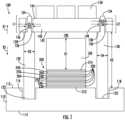
- the heat exchanger brazing fixture 100includes a baseplate 110, a first post 120, a second post 130, a top plate 140, one or more weights 150, and a spacer 160. It is understood that while two posts 120, 130 are illustrated and described, the embodiments disclosed herein may be applicable to any heat exchanger brazing fixture 100 using one or more posts.
- the heat exchanger brazing fixture 100may utilize one post.
- the heat exchanger brazing fixture 100may utilize two posts.
- the heat exchanger brazing fixture 100may utilize three posts.
- the heat exchanger brazing fixture 100may utilize four posts.
- the baseplate 110includes a first surface 112 and a second surface 114 located opposite the first surface 112.
- the base plate 110includes a first recess 116 in the first surface 112 and a second recess 118 located in the first surface 112.
- the first post 120includes a first end 122 and a second end 124 located opposite the first end 122.
- the first end 122 of the first post 120is located within the first recess 116 of the baseplate 110.
- the first end 122 of the first post 120may be operably associated with the first surface 112 by the first end 122 resting within the first recess 116 or the first end 122 being attached to the baseplate 110 either at the first surface 112 or within the first recess 116.
- the first post 120also includes an intermediate point 126 located between the first end 122 and the second end 124.
- the first post 120may have a first diameter D1 located between the second end 124 and the intermediate point 126.
- the first post 120may have a second diameter D2 located between the first end 122 and the intermediate point 126.
- the first diameter D1is less than the second diameter D2, thus creating a seat 128 at the intermediate point 126.
- the intermediate point 126 and the seat 128are located at a first distance L1 away from the second end 124.
- the second post 130includes a first end 132 and a second end 134 located opposite the first end 132.
- the first end 132 of the second post 130is located within the second recess 118 of the baseplate 110.
- the first end 132 of the second post 130may be operably associated with the first surface 112 by the first end 132 resting within the second recess 118 or the first end 132 being attached to the baseplate 110 either at the first surface 112 or within the second recess 118.
- the second post 130also includes an intermediate point 136 located between the first end 132 and the second end 134.
- the second post 130may have a third diameter D3 located between the second end 134 and the intermediate point 136.
- the second post 130may have a fourth diameter D4 located between the first end 132 and the intermediate point 136.
- the third diameter D3is less than the fourth diameter D4, thus creating a seat 138 at the intermediate point 136.
- the intermediate point 136 and the seat 138is located at a second distance L2 away from the second end 134.
- the top plate 140is configured to rest upon the seat 128 of the first post 120 and the seat 138 of the second post 130 when not in the brazing process and the heat exchanger has expanded sufficiently far enough to move the top plate 140 away from the seats 128, 138.
- the first diameter D1may be equal to the third diameter D3, the second diameter D2 may be equal to the fourth diameter D4, and the first distance L1 may be equal to the second distance L2.
- the top plate 140is operably connected to the first post 120 and/or the second post 130 and separated from the first surface 112 of the baseplate 110 by a selected distance H2.
- the top plate 140is configured to move in a first direction X1 (e.g., up) along the first post 120 and the second post 130 when a heat exchanger 200 resting on the first surface 112 of the baseplate 110 expands during a brazing process and impacts the top plate 140 either directly or through spacer 160.
- the top plate 140is configured to move in a second direction X2 (e.g., down) along the first post 120 and the second post 130 when the heat exchanger 200 resting on the first surface 112 of the baseplate 110 contracts during the brazing process.
- the top plate 140may be weighed down by its own weight and one or more weights 150 located on the top plate 140.
- the top plate 140includes a first side 142, a second side 144 opposite the first side 142, a first hole 146 extending from the first side 142 to the second side 144, and a second hole 148 extending from the first side 142 to the second side 144.
- the first hole 146has a fifth diameter D5.
- the fifth diameter D5is greater than the first diameter D1.
- the fifth diameter D5is less than the second diameter D2.
- the second end 124 of the first post 120is inserted into the first hole 146 up to the intermediate point 126 of the first post 120.
- the fifth diameter D5being greater than the first diameter D1 but less than the second diameter D2 allows the first side 142 of the top plate 140 to rest upon the seat 128 of the first post 120, as illustrated in FIG. 1
- the second hole 148has a sixth diameter D6.
- the sixth diameter D6is greater than the third diameter D3.
- the sixth diameter D6is less than the fourth diameter D4.
- the second end 134 of the second post 130is inserted into the second hole 148 up to the intermediate point 136 of the second post 130.
- the sixth diameter D6being greater than the third diameter D3 but less than the fourth diameter D4 allows the first side 142 of the top plate 140 to rest upon the seat 138 of the second post 130, as illustrated in FIG. 1
- the first post 120, the second post 130, the first hole 146, and the second hole 148may each be circular in shape.
- a heat exchanger 200is configured to rest upon the first surface 112 of the baseplate 110.
- the heat exchanger 200may be composed of alternating layers of braze foils 220, parting sheets 250, closure bars 240,and fins 230.
- the braze foils 220 and fins 230are sandwiched between a first end sheet 212 and a second end sheet 214.
- the heat exchanger 200may include one or more parting sheets 250 interposed between the braze foils 220 and fins 230, as illustrated in FIG. 1 .
- the heat exchanger 200may include one or more closure bars 240 interposed between the braze foils 220 and parting sheets 250. , as illustrated in FIG. 1 .
- the fins 230are placed within the closure bars 240.
- the first end sheet 212may rest on the first surface 112 of the baseplate 110.
- the heat exchanger brazing fixture 100may include a spacer 160 interposed between the heat exchanger 200 and the top plate 140.
- the spacer 160may be configured to move in a first direction X1 when the heat exchanger 200 expands during the brazing process.
- the spacer 160may be configured to move in a first direction X1 and impact the first side 142 of the top plate 140 when the heat exchanger 200 expands during the brazing process.
- the spacer 160is configured to rest on the heat exchanger 200. More specifically, the spacer 160 is configured to rest on the second end sheet 214.
- the one or more weights 150are configured to rest on the second side 144 of the top plate 140.
- the heat exchanger 200 and spacer 160When the heat exchanger 200 is being brazed at high temperatures, the heat exchanger 200 and spacer 160 will expand in a first direction X1.
- the first directionmay be upward. Gravity may point in a second direction X2 oriented opposite the first direction X1.
- the spacer 160will move in the first direction X1 towards the top plate 140.
- the heat exchanger 200may continue to expand in the first direction X1 and may lift the top plate 140 off of the seat 128 of the first post 120 and/or the seat 138 of the second post 130.
- the weight of the top plate 140 and weight of the weights 150will be supported by the spacer 160 and the heat exchanger 200, thus exerting a pressure on the heat exchanger 200.
- the heat exchanger 200is known to expand at a known rate under a known heat load during brazing, thus it may be determined when the spacer will impact the first side 142 of the top plate 140.
- a height H1 of the spacer 160 and/or a selected distance H2 between the first side 142 of the top plate 140may be adjusted and specifically chosen so that the heat exchanger 200 may experience no externally applied load other than the spacer 160 until an appropriate time.
- the appropriate timemay depend on a ramp up rate and a total mass of heat exchanger 200, spacer 160, and weights 150.
- the appropriate timemay also depend on the temperature chosen at which the heat exchanger 200 and spacer 160 make contact with the top plate 140. This temperature should always be below the solidus of the braze foil 220.
- the appropriate timewill also depend upon the height H1 of the spacer 160 and gap 190.
- the spacer 160has a height H1 sized to maintain a gap 190 between the spacer 160 and the first side 142 of the top plate 140 at room temperature prior to start of the brazing process.
- the gap 190gets smaller as the temperature rises.
- the spacer 160may be composed of a corrosion-resistant steel (CRES), such as, for example, CRES 347.
- CREScorrosion-resistant steel
- the first post 120 and the second post 130shall be composed of graphite.
- the graphitehas a very low coefficient of thermal expansion, and the CRES 347 has a very high coefficient of thermal expansion, thus the graphite will expand very little and the CRES 347 will expand a lot more during the braze process.
- the spacer 160may be attached to the first side 142 of the top plate 140, rather than resting on the second end sheet 214.
- FIG. 2a flow chart of method 600 of brazing a heat exchanger 200 using a heat exchanger brazing fixture 100 is illustrated, in accordance with an embodiment of the disclosure.
- the heat exchanger 200is placed on a baseplate 110 of the heat exchanger brazing fixture 100.
- the baseplate 110includes a first surface 112 and a second surface 114 opposite the first surface 112.
- the heat exchanger 200may rest upon the first surface 112.
- a top plate 140is operably connected to a first post 120 of the heat exchanger brazing fixture 100.
- the first postincludes a first end 122 and a second end 124 located opposite the first end 122.
- the first post 120is attached to the first surface 112 of the baseplate 110 at the first end 122.
- the top plate 140is separated from the first surface 112 of the baseplate 110 by a selected distance H2.
- the top plate 140is configured to move in a first direction X1 along the first post 120 when the heat exchanger 200 resting upon the first surface 112 of the baseplate 110 expands during a brazing process.
- the top plate 140may be operably connected to the first post 120 by inserting the second end 124 of the first post 120 through a first hole 146 in the top plate 140.
- the temperature of the heat exchanger 200is increased to perform the brazing process.
- the method 600may further include that one or more weights 150 are placed on top of the top plate 140.
- the method 600may further include that a spacer 160 is placed in between the heat exchanger 200 and the top plate 140.
- the method 600may further include that a spacer 160 is placed on top of the heat exchanger 200 in between the heat exchanger 200 and the top plate 140.
- the method 600may further include that the top plate 140 is operably connected to a second post 130 of the heat exchanger brazing fixture 100.
- the second post 130including a first end 132 of the second post 130 and a second end 134 of the second post 130 located opposite the first end 132 of the second post 130.
- the second post 130is attached to the first surface 112 of the baseplate 110 at the first end 132.
- the top plate 140may be operably connected to the second post 130 by inserting the second end 134 of the second post 130 through a second hole 148 in the top plate 140.
- the heat exchanger 200is allowed to expand for a selected period of time in the first direction X1 during the brazing process prior to moving the top plate 140 in the first direction X1.
Landscapes
- Engineering & Computer Science (AREA)
- Mechanical Engineering (AREA)
- Physics & Mathematics (AREA)
- Optics & Photonics (AREA)
- Details Of Heat-Exchange And Heat-Transfer (AREA)
Description
- The subject matter disclosed herein relates generally to the field of heat exchangers, and specifically to an apparatus and method for brazing heat exchangers.
US 4 155 157 A discloses a fixture for brazing a heat exchanger. The heat exchanger is clamped between two plates to allow a controlled expansion while being heated. An additional plate, acting as a spacer is placed in between the heat exchanger and the top plate.CN 109 551 076 A discloses a fixture for brazing a heat exchanger. The heat exchanger is clamped between two plates to allow a controlled expansion while being heated. Between the heat exchanger and the top plate, a spring loaded pressure plate is arranged.US 4 128 235 A discloses a fixture for brazing a heat exchanger. The heat exchanger is clamped between two plates to allow a controlled expansion while being heated. The top plate comprises a spacer, which is placed on top of the heat exchanger.DE 10 2014 218693 A1 discloses a fixture for brazing a heat exchanger. The heat exchanger is clamped between two plates to allow a controlled expansion while being heated. Spacers, realized by pneumatic springs, are placed in between the heat exchanger and the top plate.- Components of a heat exchangers often need to be clamped under constant pressure during a brazing process, which may result in bowing in some of the final sheets of the heat exchanger.
- A heat exchanger brazing fixture is provided. The heat exchanger brazing fixture including: a baseplate including a first surface and a second surface located opposite the first surface and a first post including a first end and a second end located opposite the first end. The first post is operably associated with the first surface of the baseplate at the first end. The heat exchanger brazing fixture further including a top plate operably connected to the first post and separated from the first surface of the baseplate by a selected distance. The top plate being configured to move in a first direction along the first post when a heat exchanger resting upon the first surface of the baseplate expands during a brazing process.
- In addition to one or more of the features described above, or as an alternative, further embodiments may include that the first post further includes an intermediate point between the first end and the second end, the first post having a first diameter located between the second end and the intermediate point and a second diameter located between the first end and the intermediate point. The first diameter is less than the second diameter.
- In addition to one or more of the features described above, or as an alternative, the heat exchanger brazing fixture includes that the top plate further includes a first side, a second side opposite the first side, and a first hole extending from the first side to the second side. The second end of the first post is inserted into the first hole up to the intermediate point of the first post.
- In addition to one or more of the features described above, or as an alternative, the heat exchanger brazing fixture includes that a seat is located at the intermediate point and the top plate is configured to rest on the seat of the first post.
- In addition to one or more of the features described above, or as an alternative, the heat exchanger brazing fixture includes one or more weights configured to weigh down the top plate.
- In addition to one or more of the features described above, or as an alternative, the heat exchanger brazing fixture includes a spacer configured to rest on the heat exchanger.
- In addition to one or more of the features described above, or as an alternative, the heat exchanger brazing fixture includes a spacer interposed between the heat exchanger and the top plate, the spacer being configured to move in the first direction when the heat exchanger expands during the brazing process.
- In addition to one or more of the features described above, or as an alternative, the heat exchanger brazing fixture includes a spacer interposed between the heat exchanger and the top plate. The spacer being configured to move in the first direction and impact the first side of the top plate when the heat exchanger expands during the brazing process.
- In addition to one or more of the features described above, or as an alternative, the heat exchanger brazing fixture includes a second post including a first end of the second post and a second end of the second post located opposite the first end of the second post. The second post is operably associated with the first surface of the baseplate at the first end of the second post.
- In addition to one or more of the features described above, or as an alternative, the heat exchanger brazing fixture includes that the second post further includes an intermediate point of the second post between the first end of the second post and the second end of the second post. The second post having a third diameter located between the second end of the second post and the intermediate point of the second post and a fourth diameter located between the first end of the second post and the intermediate point of the second post. The third diameter is less than the fourth diameter.
- In addition to one or more of the features described above, or as an alternative, the heat exchanger brazing fixture includes that the top plate further includes a second hole extending from the first side to the second side. The second end of the second post is inserted into the second hole up to the intermediate point of the second post.
- In addition to one or more of the features described above, or as an alternative, the heat exchanger brazing fixture includes that a seat of the first post is located at the intermediate point of the first post and a seat of the second post is located at the intermediate point of the second post. The top plate is configured to rest on the seat of the first post and the seat of the second post.
- A method of brazing a heat exchanger using a heat exchanger brazing fixture is provided. The method including: placing the heat exchanger on a baseplate of the heat exchanger brazing fixture, the baseplate including a first surface and a second surface opposite the first surface, the heat exchanger resting upon the first surface; operably connecting a top plate to a first post of the heat exchanger brazing fixture, the first post including a first end and a second end located opposite the first end. The first post is operably associated with the first surface of the baseplate at the first end. The top plate is separated from the first surface of the baseplate by a selected distance, the top plate being configured to move in a first direction along the first post when the heat exchanger resting upon the first surface of the baseplate expands during a brazing process; and increasing a temperature of the heat exchanger to perform the brazing process.
- In addition to one or more of the features described above, or as an alternative, the method of brazing a heat exchanger using a heat exchanger brazing fixture includes placing one or more weights on top of the top plate.
- In addition to one or more of the features described above, or as an alternative, the method of brazing a heat exchanger using a heat exchanger brazing fixture includes placing a spacer in between the heat exchanger and the top plate.
- In addition to one or more of the features described above, or as an alternative, the method of brazing a heat exchanger using a heat exchanger brazing fixture includes placing a spacer on top of the heat exchanger in between the heat exchanger and the top plate.
- In addition to one or more of the features described above, or as an alternative, the method of brazing a heat exchanger using a heat exchanger brazing fixture includes inserting the second end of the first post through a first hole in the top plate.
- In addition to one or more of the features described above, or as an alternative, the method of brazing a heat exchanger using a heat exchanger brazing fixture includes operably connecting the top plate to a second post of the heat exchanger brazing fixture, the second post including a first end of the second post and a second end of the second post located opposite the first end of the second post. The second post is operably associated with the first surface of the baseplate at the first end of the second post.
- In addition to one or more of the features described above, or as an alternative, the method of brazing a heat exchanger using a heat exchanger brazing fixture includes inserting the second end of the second post through a second hole in the top plate.
- In addition to one or more of the features described above, or as an alternative, the method of brazing a heat exchanger using a heat exchanger brazing fixture includes allowing the heat exchanger to expand for a selected period of time in the first direction during the brazing process prior to moving the top plate in the first direction.
- The foregoing features and elements may be combined in various combinations without exclusivity, unless expressly indicated otherwise. These features and elements as well as the operation thereof will become more apparent in light of the following description and the accompanying drawings.
- With reference to the accompanying drawings, like elements are numbered alike:
FIG. 1 illustrates a cross-sectional view of a heat exchanger brazing fixture, according to an embodiment of the present disclosure; andFIG. 2 illustrates a flow chart of a method of brazing a heat exchanger using a heat exchanger brazing fixture, in accordance with an embodiment of the present disclosure.- A detailed description of of the disclosed apparatus and method are presented herein by way of exemplification with reference to the Figures.
- Heat exchangers are typically constructed utilizing alternating layers of parting sheets, closure bars, fins and brazing sheets, foils, which are clamped together and then brazed at high temperatures e.g., 1066°C (1950°F). The fins may be captured with the closure bars which are designed as a frame within which the fins are placed. The high temperatures of the brazing process results in expansion of the layers of closure bars, parting sheets and brazing sheets. This expansion causes the parting sheets to bow due to the clamping of the layers. This expansion in turn causes the fins to bow. Embodiments disclosed herein seek to allow the layers of fins to expand freely during high temperatures of the brazing process to a hard limit or stopping point, which helps to avoid bowing of the parting sheets and in turn the fins.
- Referring now to
FIGS. 1 , a cross-sectional view of a heatexchanger brazing fixture 100, according to the present disclosure. The heatexchanger brazing fixture 100 includes abaseplate 110, afirst post 120, asecond post 130, atop plate 140, one ormore weights 150, and aspacer 160. It is understood that while twoposts exchanger brazing fixture 100 using one or more posts. For example, the heatexchanger brazing fixture 100 may utilize one post. In another embodiment, the heatexchanger brazing fixture 100 may utilize two posts. In yet another embodiment, the heatexchanger brazing fixture 100 may utilize three posts. In still yet another embodiment, the heatexchanger brazing fixture 100 may utilize four posts. - The
baseplate 110 includes a first surface 112 and asecond surface 114 located opposite the first surface 112. Thebase plate 110 includes afirst recess 116 in the first surface 112 and asecond recess 118 located in the first surface 112. - The
first post 120 includes afirst end 122 and asecond end 124 located opposite thefirst end 122. Thefirst end 122 of thefirst post 120 is located within thefirst recess 116 of thebaseplate 110. Thefirst end 122 of thefirst post 120 may be operably associated with the first surface 112 by thefirst end 122 resting within thefirst recess 116 or thefirst end 122 being attached to thebaseplate 110 either at the first surface 112 or within thefirst recess 116. Thefirst post 120 also includes anintermediate point 126 located between thefirst end 122 and thesecond end 124. Thefirst post 120 may have a first diameter D1 located between thesecond end 124 and theintermediate point 126. Thefirst post 120 may have a second diameter D2 located between thefirst end 122 and theintermediate point 126. The first diameter D1 is less than the second diameter D2, thus creating a seat 128 at theintermediate point 126. Theintermediate point 126 and the seat 128 are located at a first distance L1 away from thesecond end 124. - The
second post 130 includes afirst end 132 and asecond end 134 located opposite thefirst end 132. Thefirst end 132 of thesecond post 130 is located within thesecond recess 118 of thebaseplate 110. Thefirst end 132 of thesecond post 130 may be operably associated with the first surface 112 by thefirst end 132 resting within thesecond recess 118 or thefirst end 132 being attached to thebaseplate 110 either at the first surface 112 or within thesecond recess 118. Thesecond post 130 also includes anintermediate point 136 located between thefirst end 132 and thesecond end 134. Thesecond post 130 may have a third diameter D3 located between thesecond end 134 and theintermediate point 136. Thesecond post 130 may have a fourth diameter D4 located between thefirst end 132 and theintermediate point 136. The third diameter D3 is less than the fourth diameter D4, thus creating aseat 138 at theintermediate point 136. Theintermediate point 136 and theseat 138 is located at a second distance L2 away from thesecond end 134. - The
top plate 140 is configured to rest upon the seat 128 of thefirst post 120 and theseat 138 of thesecond post 130 when not in the brazing process and the heat exchanger has expanded sufficiently far enough to move thetop plate 140 away from theseats 128, 138. - The first diameter D1 may be equal to the third diameter D3, the second diameter D2 may be equal to the fourth diameter D4, and the first distance L1 may be equal to the second distance L2.
- The
top plate 140 is operably connected to thefirst post 120 and/or thesecond post 130 and separated from the first surface 112 of thebaseplate 110 by a selected distance H2. Thetop plate 140 is configured to move in a first direction X1 (e.g., up) along thefirst post 120 and thesecond post 130 when aheat exchanger 200 resting on the first surface 112 of thebaseplate 110 expands during a brazing process and impacts thetop plate 140 either directly or throughspacer 160. Thetop plate 140 is configured to move in a second direction X2 (e.g., down) along thefirst post 120 and thesecond post 130 when theheat exchanger 200 resting on the first surface 112 of thebaseplate 110 contracts during the brazing process. - The
top plate 140 may be weighed down by its own weight and one ormore weights 150 located on thetop plate 140. Thetop plate 140 includes afirst side 142, asecond side 144 opposite thefirst side 142, afirst hole 146 extending from thefirst side 142 to thesecond side 144, and asecond hole 148 extending from thefirst side 142 to thesecond side 144. - The
first hole 146 has a fifth diameter D5. The fifth diameter D5 is greater than the first diameter D1. The fifth diameter D5 is less than the second diameter D2. Thesecond end 124 of thefirst post 120 is inserted into thefirst hole 146 up to theintermediate point 126 of thefirst post 120. The fifth diameter D5 being greater than the first diameter D1 but less than the second diameter D2 allows thefirst side 142 of thetop plate 140 to rest upon the seat 128 of thefirst post 120, as illustrated inFIG. 1 - The
second hole 148 has a sixth diameter D6. The sixth diameter D6 is greater than the third diameter D3. The sixth diameter D6 is less than the fourth diameter D4. Thesecond end 134 of thesecond post 130 is inserted into thesecond hole 148 up to theintermediate point 136 of thesecond post 130. The sixth diameter D6 being greater than the third diameter D3 but less than the fourth diameter D4 allows thefirst side 142 of thetop plate 140 to rest upon theseat 138 of thesecond post 130, as illustrated inFIG. 1 - The
first post 120, thesecond post 130, thefirst hole 146, and thesecond hole 148 may each be circular in shape. - A
heat exchanger 200 is configured to rest upon the first surface 112 of thebaseplate 110. Theheat exchanger 200 may be composed of alternating layers of braze foils 220, partingsheets 250, closure bars 240,andfins 230. The braze foils 220 andfins 230 are sandwiched between afirst end sheet 212 and asecond end sheet 214. Theheat exchanger 200 may include one ormore parting sheets 250 interposed between the braze foils 220 andfins 230, as illustrated inFIG. 1 . Theheat exchanger 200 may include one or more closure bars 240 interposed between the braze foils 220 andparting sheets 250. , as illustrated inFIG. 1 . Thefins 230 are placed within the closure bars 240. Thefirst end sheet 212 may rest on the first surface 112 of thebaseplate 110. - The heat
exchanger brazing fixture 100 may include aspacer 160 interposed between theheat exchanger 200 and thetop plate 140. Thespacer 160 may be configured to move in a first direction X1 when theheat exchanger 200 expands during the brazing process. Thespacer 160 may be configured to move in a first direction X1 and impact thefirst side 142 of thetop plate 140 when theheat exchanger 200 expands during the brazing process. - The
spacer 160 is configured to rest on theheat exchanger 200. More specifically, thespacer 160 is configured to rest on thesecond end sheet 214. The one ormore weights 150 are configured to rest on thesecond side 144 of thetop plate 140. - When the
heat exchanger 200 is being brazed at high temperatures, theheat exchanger 200 andspacer 160 will expand in a first direction X1. The first direction may be upward. Gravity may point in a second direction X2 oriented opposite the first direction X1. As theheat exchanger 200 expands, thespacer 160 will move in the first direction X1 towards thetop plate 140. Once thespacer 160 contacts thetop plate 140, theheat exchanger 200 may continue to expand in the first direction X1 and may lift thetop plate 140 off of the seat 128 of thefirst post 120 and/or theseat 138 of thesecond post 130. Once thetop plate 140 begins to lift off of the seat 128 of thefirst post 120 and/or theseat 138 of thesecond post 130, the weight of thetop plate 140 and weight of theweights 150 will be supported by thespacer 160 and theheat exchanger 200, thus exerting a pressure on theheat exchanger 200. - The
heat exchanger 200 is known to expand at a known rate under a known heat load during brazing, thus it may be determined when the spacer will impact thefirst side 142 of thetop plate 140. A height H1 of thespacer 160 and/or a selected distance H2 between thefirst side 142 of thetop plate 140 may be adjusted and specifically chosen so that theheat exchanger 200 may experience no externally applied load other than thespacer 160 until an appropriate time. The appropriate time may depend on a ramp up rate and a total mass ofheat exchanger 200,spacer 160, andweights 150. The appropriate time may also depend on the temperature chosen at which theheat exchanger 200 andspacer 160 make contact with thetop plate 140. This temperature should always be below the solidus of thebraze foil 220. The appropriate time will also depend upon the height H1 of thespacer 160 andgap 190. Thespacer 160 has a height H1 sized to maintain agap 190 between thespacer 160 and thefirst side 142 of thetop plate 140 at room temperature prior to start of the brazing process. Thegap 190 gets smaller as the temperature rises. - In an embodiment, the
spacer 160 may be composed of a corrosion-resistant steel (CRES), such as, for example, CRES 347. In another embodiment, thefirst post 120 and thesecond post 130 shall be composed of graphite. Advantageously, the graphite has a very low coefficient of thermal expansion, and the CRES 347 has a very high coefficient of thermal expansion, thus the graphite will expand very little and the CRES 347 will expand a lot more during the braze process. - In an alternative embodiment, the
spacer 160 may be attached to thefirst side 142 of thetop plate 140, rather than resting on thesecond end sheet 214. - Referring now to
FIG. 2 , with continued reference toFIG. 1 , a flow chart ofmethod 600 of brazing aheat exchanger 200 using a heatexchanger brazing fixture 100 is illustrated, in accordance with an embodiment of the disclosure. - At block 602, the
heat exchanger 200 is placed on abaseplate 110 of the heatexchanger brazing fixture 100. Thebaseplate 110 includes a first surface 112 and asecond surface 114 opposite the first surface 112. Theheat exchanger 200 may rest upon the first surface 112. - At
block 604, atop plate 140 is operably connected to afirst post 120 of the heatexchanger brazing fixture 100. The first post includes afirst end 122 and asecond end 124 located opposite thefirst end 122. Thefirst post 120 is attached to the first surface 112 of thebaseplate 110 at thefirst end 122. Thetop plate 140 is separated from the first surface 112 of thebaseplate 110 by a selected distance H2. Thetop plate 140 is configured to move in a first direction X1 along thefirst post 120 when theheat exchanger 200 resting upon the first surface 112 of thebaseplate 110 expands during a brazing process. Thetop plate 140 may be operably connected to thefirst post 120 by inserting thesecond end 124 of thefirst post 120 through afirst hole 146 in thetop plate 140. - At
block 606, the temperature of theheat exchanger 200 is increased to perform the brazing process. - The
method 600 may further include that one ormore weights 150 are placed on top of thetop plate 140. Themethod 600 may further include that aspacer 160 is placed in between theheat exchanger 200 and thetop plate 140. Themethod 600 may further include that aspacer 160 is placed on top of theheat exchanger 200 in between theheat exchanger 200 and thetop plate 140. - The
method 600 may further include that thetop plate 140 is operably connected to asecond post 130 of the heatexchanger brazing fixture 100. Thesecond post 130 including afirst end 132 of thesecond post 130 and asecond end 134 of thesecond post 130 located opposite thefirst end 132 of thesecond post 130. Thesecond post 130 is attached to the first surface 112 of thebaseplate 110 at thefirst end 132. Thetop plate 140 may be operably connected to thesecond post 130 by inserting thesecond end 134 of thesecond post 130 through asecond hole 148 in thetop plate 140. - The
heat exchanger 200 is allowed to expand for a selected period of time in the first direction X1 during the brazing process prior to moving thetop plate 140 in the first direction X1. - Technical effects and benefits of the features described herein include allowing the heat exchanger to expand freely (e.g., with only weight of a
spacer 160 and unclamped) in a first direction for a selected amount of time prior to impacting atop plate 140. - A detailed description of the disclosed apparatus and method are presented herein by way of exemplification and with reference to the Figures.
- The term "about" is intended to include the degree of error associated with measurement of the particular quantity based upon the equipment available at the time of filing the application.
- The terminology used herein is for the purpose of describing particular embodiments only and is not intended to be limiting of the present disclosure. As used herein, the singular forms "a", "an" and "the" are intended to include the plural forms as well, unless the context clearly indicates otherwise. It will be further understood that the terms "comprises" and/or "comprising," when used in this specification, specify the presence of stated features, integers, steps, operations, elements, and/or components, but do not preclude the presence or addition of one or more other features, integers, steps, operations, element components, and/or groups thereof.
Claims (15)
- A heat exchanger brazing fixture (100), comprising:a baseplate (110) comprising a first surface and a second surface located opposite the first surface; anda first post (120) comprising a first end and a second end located opposite the first end, the first post (120) is associated with the first surface of the baseplate (110) at the first end, the heat exchanger brazing fixturecharacterized bya top plate (140) resting upon the first post (120) and separated from the first surface of the baseplate (110) by a selected distance, the top plate (140) being configured to move in an upward direction along the first post (120) and away from the baseplate (110), when a heat exchanger resting upon the first surface of the baseplate (110) expands during a brazing process; and a spacer (160) interposed between the heat exchanger and the top plate (140), the spacer (160) being configured to rest on the heat exchanger, wherein the spacer (160) is separated from the top plate (140) by a gap at room temperature prior to the brazing process, and the gap is configured to decrease as temperature increases during the brazing process and the heat exchanger expands, the spacer (160) configured to impact the top plate (140) and move the top plate (140) in the upward direction due to expansion of the heat exchanger.
- The heat exchanger brazing fixture (100) of claim 1, wherein the first post (120) further comprises an intermediate point (136) between the first end and the second end, the first post (120) having a first diameter located between the second end and the intermediate point (136) and a second diameter located between the first end and the intermediate point (136), and wherein the first diameter is less than the second diameter.
- The heat exchanger brazing fixture (100) of claim 2, wherein the top plate (140) further comprises a first side, a second side opposite the first side, and a first hole extending from the first side to the second side, and wherein the second end of the first post (120) is inserted into the first hole up to the intermediate point (136) of the first post.
- The heat exchanger brazing fixture (100) of claim 3, wherein a seat (128) is located at the intermediate point (136) and the top plate (140) is configured to rest on an upper surface of the seat of the first post (120).
- The heat exchanger brazing fixture (100) of claim 3, further comprising a second post (130) comprising a first end of the second post (130) and a second end of the second post located opposite the first end of the second post, the second post (130) is associated with the first surface of the baseplate (110) at the first end of the second post (130).
- The heat exchanger brazing fixture (100) of claim 5, wherein the second post (130) further comprises an intermediate point (136) of the second post (130) between the first end of the second post (130) and the second end of the second post (130), the second post (130) having a third diameter located between the second end of the second post (130) and the intermediate point (136) of the second post (130) and a fourth diameter located between the first end of the second post (130) and the intermediate point (136) of the second post (130), and wherein the third diameter is less than the fourth diameter.
- The heat exchanger brazing fixture (100) of claim 6, wherein the top plate (140) further comprises a second hole extending from the first side to the second side, and wherein the second end of the second post (130) is inserted into the second hole up to the intermediate point (136) of the second post (130).
- The heat exchanger brazing fixture (100) of claim 7 wherein a seat (128) of the first post (120) is located at the intermediate point (136) of the first post (120) and a seat of the second post (130) is located at the intermediate point of the second post (130), wherein the top plate (140) is configured to rest on an upper surface of the seat (128) of the first post (120) and rest on an upper surface of the seat (138) of the second post (130).
- A method (600) of brazing a heat exchanger using a heat exchanger brazing fixture (100), comprising:placing (604) the heat exchanger on a baseplate (110) of the heat exchanger brazing fixture (100), the baseplate (110) comprising a first surface and a second surface opposite the first surface, the heat exchanger resting upon the first surface; the methodcharacterized by: connecting (606) a top plate (140) to a first post (120) of the heat exchanger brazing fixture (100), the first post (120) comprising a first end and a second end located opposite the first end, wherein the first post (120) is associated with the first surface of the baseplate (110) at the first end, and wherein the top plate (140) is separated from the first surface of the baseplate (110) by a selected distance, the top plate (140) being configured to move in an upward direction along the first post (120) when the heat exchanger resting upon the first surface of the baseplate (110) expands during a brazing process;interposing a spacer (160) interposed between the heat exchanger and the top plate (140), the spacer (160) being configured to rest on the heat exchanger, wherein the spacer (160) is separated from the top plate (140) by a gap at room temperature prior to the brazing process, and the gap is configured to decrease as temperature increases during the brazing process and the heat exchanger expands, the spacer (160) configured to impact the top plate (140) and move the top plate (140) in the upward direction due to expansion of the heat exchanger; andincreasing (608) a temperature of the heat exchanger to perform the brazing process.
- The method of claim 9, further comprising:
placing one or more weights on top of the top plate. - The method of claim 10, further comprising: wherein interposing the spacer (160) includes at least one of:placing a spacer (160) in between the heat exchanger and the top plate (140), andplacing a spacer (160) on top of the heat exchanger (200) in between the heat exchanger (200) and the top plate (140).
- The method of any of claims 9 to 11, further comprising:
inserting the second end of the first post (120) through a first hole in the top plate (140). - The method of any of claims 10 to 12, further comprising:
connecting the top plate (140) to a second post (130) of the heat exchanger (200) brazing fixture, the second post (130) comprising a first end of the second post (130) and a second end of the second post (130) located opposite the first end of the second post (130), wherein the second post (130) is associated with the first surface of the baseplate (110) at the first end of the second post (130) - The method of claim 13 further comprising:
inserting the second end of the second post (130) through a second hole in the top plate. - The method of any of claims 9 to 14, further comprising:
allowing the heat exchanger (200) to expand for a selected period of time in the upward direction during the brazing process prior to moving the top plate (140) in the upward direction.
Applications Claiming Priority (1)
| Application Number | Priority Date | Filing Date | Title |
|---|---|---|---|
| US17/097,134US11559846B2 (en) | 2020-11-13 | 2020-11-13 | Brazing by expansion using a spacer |
Publications (2)
| Publication Number | Publication Date |
|---|---|
| EP4000781A1 EP4000781A1 (en) | 2022-05-25 |
| EP4000781B1true EP4000781B1 (en) | 2024-04-10 |
Family
ID=78598783
Family Applications (1)
| Application Number | Title | Priority Date | Filing Date |
|---|---|---|---|
| EP21207471.0AActiveEP4000781B1 (en) | 2020-11-13 | 2021-11-10 | Brazing by expansion |
Country Status (2)
| Country | Link |
|---|---|
| US (1) | US11559846B2 (en) |
| EP (1) | EP4000781B1 (en) |
Families Citing this family (1)
| Publication number | Priority date | Publication date | Assignee | Title |
|---|---|---|---|---|
| ES2988037T3 (en)* | 2022-01-10 | 2024-11-19 | Benteler Automobiltechnik Gmbh | Hot forming process and tool for producing a heat exchanger plate |
Citations (2)
| Publication number | Priority date | Publication date | Assignee | Title |
|---|---|---|---|---|
| US4128235A (en)* | 1977-09-01 | 1978-12-05 | United Aircraft Products, Inc. | Braze fixture |
| DE102014218693A1 (en)* | 2014-09-17 | 2016-03-17 | Mahle International Gmbh | Arrangement and method for producing a cohesive connection |
Family Cites Families (19)
| Publication number | Priority date | Publication date | Assignee | Title |
|---|---|---|---|---|
| US3941293A (en)* | 1969-09-22 | 1976-03-02 | Societe Anonyme Des Usines Chausson | Brazing jig for aluminum radiator cores |
| FR2303622A1 (en)* | 1975-03-10 | 1976-10-08 | Microturbo Sa | METHOD OF MANUFACTURING A UNIT OF THE HEAT EXCHANGER TYPE |
| US4155157A (en)* | 1978-03-06 | 1979-05-22 | United Aircraft Products, Inc. | Braze fixture |
| US4429824A (en)* | 1981-09-17 | 1984-02-07 | Rohr Industries, Inc. | Delta-alpha bond/superplastic forming method of fabricating titanium structures and the structures resulting therefrom |
| CA1313184C (en) | 1989-03-28 | 1993-01-26 | David G. Rowntree | Heat exchanger manufacturing method and apparatus |
| US5176499A (en)* | 1991-06-24 | 1993-01-05 | General Electric Company | Photoetched cooling slots for diffusion bonded airfoils |
| JP3330037B2 (en)* | 1996-11-29 | 2002-09-30 | 富士通株式会社 | Method and apparatus for joining chip components |
| US5927589A (en)* | 1997-11-25 | 1999-07-27 | Lucent Technologies Inc. | Method and fixture for use in bonding a chip to a substrate |
| US6206272B1 (en)* | 1999-04-08 | 2001-03-27 | Intel Corporation | Alignment weight for floating field pin design |
| US6129257A (en)* | 1999-12-01 | 2000-10-10 | Allison Engine Company, Inc. | High temperature brazing fixture |
| DE10024111B4 (en)* | 2000-05-18 | 2006-02-23 | Robert Bosch Gmbh | Method for producing a component from plates which have been stacked and soldered to one another |
| US7118021B2 (en)* | 2003-11-26 | 2006-10-10 | Siemens Power Generation, Inc. | Bonding fixture |
| EP1579942A1 (en) | 2004-03-26 | 2005-09-28 | Balcke-Dürr GmbH | Method of manufacturing a heat exchanger |
| US8342383B2 (en)* | 2006-07-06 | 2013-01-01 | Praxair Technology, Inc. | Method for forming sputter target assemblies having a controlled solder thickness |
| JP2008036650A (en) | 2006-08-02 | 2008-02-21 | Denso Corp | Method of manufacturing heat exchanger |
| US20100133325A1 (en)* | 2008-12-01 | 2010-06-03 | Xerox Corporation | Unified metal alloying in a diffusion furnace |
| KR101583921B1 (en)* | 2014-05-02 | 2016-01-11 | 현대자동차주식회사 | Method and apparatus for manufacturing heat exchanger for vehicle |
| US10319619B2 (en)* | 2014-12-05 | 2019-06-11 | Samsung Electronics Co., Ltd. | Equipment for manufacturing semiconductor devices and method for use of same for manufacturing semiconductor package components |
| CN109551076A (en) | 2019-01-01 | 2019-04-02 | 贵州贵航汽车零部件股份有限公司 | Stacked oil cooler vacuum brazing clamp |
- 2020
- 2020-11-13USUS17/097,134patent/US11559846B2/enactiveActive
- 2021
- 2021-11-10EPEP21207471.0Apatent/EP4000781B1/enactiveActive
Patent Citations (2)
| Publication number | Priority date | Publication date | Assignee | Title |
|---|---|---|---|---|
| US4128235A (en)* | 1977-09-01 | 1978-12-05 | United Aircraft Products, Inc. | Braze fixture |
| DE102014218693A1 (en)* | 2014-09-17 | 2016-03-17 | Mahle International Gmbh | Arrangement and method for producing a cohesive connection |
Also Published As
| Publication number | Publication date |
|---|---|
| US11559846B2 (en) | 2023-01-24 |
| US20220152717A1 (en) | 2022-05-19 |
| EP4000781A1 (en) | 2022-05-25 |
Similar Documents
| Publication | Publication Date | Title |
|---|---|---|
| EP4000781B1 (en) | Brazing by expansion | |
| US3757856A (en) | Primary surface heat exchanger and manufacture thereof | |
| US4155157A (en) | Braze fixture | |
| CN106839831B (en) | A kind of compact efficient heat exchanger core body and its welding tooling | |
| KR101576707B1 (en) | Compressive rod assembly for molten metal containment structure | |
| US6997141B2 (en) | Anti-vibration support for steam generator heat transfer tubes and method for making same | |
| WO2003028141A2 (en) | Solid oxide fuel cell compression bellows | |
| US4480165A (en) | Braze fixture and method of using | |
| CN101890551A (en) | Heat exchanger holding device | |
| JP6024436B2 (en) | Slide base structure of exhaust heat recovery boiler support device and construction method thereof | |
| JP5251677B2 (en) | Circuit board bonding jig and circuit board manufacturing method | |
| US3924441A (en) | Primary surface heat exchanger and manufacture thereof | |
| KR101652726B1 (en) | Coil skid for ammealing furnace | |
| JP2010238900A (en) | Circuit board connecting tool, and method of manufacturing circuit board | |
| US20190128616A1 (en) | Method and apparatus for producing a brazed plate heat exchanger block by sectional brazing | |
| JP2005230856A (en) | Diffusion welding tool and diffusion welding method using the tool | |
| JP2005246472A (en) | Brazing apparatus and brazing method | |
| CN207267018U (en) | A kind of hot riveting machine for being used to assemble voice coil motor | |
| CN102537615B (en) | Adjustable support frame and design method for low temperature experiment of materials with low linear expansion coefficient | |
| EP2326439B1 (en) | Improved method and apparatus for bending a micro-channel heat exchanger | |
| JP2976258B2 (en) | Hot press insulation mounting structure | |
| JP2004181518A (en) | Tool for diffusion bonding, and diffusion bonding method using the same | |
| US20130240193A1 (en) | Method of manufacturing a heat exchanger block, spacer means therefor, and heat exchanger block | |
| JP6551543B2 (en) | electronic balance | |
| CN114373558B (en) | A test bench for high temperature reactor control rod drive mechanism |
Legal Events
| Date | Code | Title | Description |
|---|---|---|---|
| PUAI | Public reference made under article 153(3) epc to a published international application that has entered the european phase | Free format text:ORIGINAL CODE: 0009012 | |
| STAA | Information on the status of an ep patent application or granted ep patent | Free format text:STATUS: THE APPLICATION HAS BEEN PUBLISHED | |
| AK | Designated contracting states | Kind code of ref document:A1 Designated state(s):AL AT BE BG CH CY CZ DE DK EE ES FI FR GB GR HR HU IE IS IT LI LT LU LV MC MK MT NL NO PL PT RO RS SE SI SK SM TR | |
| STAA | Information on the status of an ep patent application or granted ep patent | Free format text:STATUS: REQUEST FOR EXAMINATION WAS MADE | |
| 17P | Request for examination filed | Effective date:20221124 | |
| RBV | Designated contracting states (corrected) | Designated state(s):AL AT BE BG CH CY CZ DE DK EE ES FI FR GB GR HR HU IE IS IT LI LT LU LV MC MK MT NL NO PL PT RO RS SE SI SK SM TR | |
| GRAP | Despatch of communication of intention to grant a patent | Free format text:ORIGINAL CODE: EPIDOSNIGR1 | |
| STAA | Information on the status of an ep patent application or granted ep patent | Free format text:STATUS: GRANT OF PATENT IS INTENDED | |
| RIC1 | Information provided on ipc code assigned before grant | Ipc:B23K 101/14 20060101ALN20231107BHEP Ipc:B23K 37/04 20060101ALI20231107BHEP Ipc:B23K 3/08 20060101ALI20231107BHEP Ipc:B23K 1/00 20060101AFI20231107BHEP | |
| RIC1 | Information provided on ipc code assigned before grant | Ipc:B23K 101/14 20060101ALN20231114BHEP Ipc:B23K 37/04 20060101ALI20231114BHEP Ipc:B23K 3/08 20060101ALI20231114BHEP Ipc:B23K 1/00 20060101AFI20231114BHEP | |
| INTG | Intention to grant announced | Effective date:20231128 | |
| GRAS | Grant fee paid | Free format text:ORIGINAL CODE: EPIDOSNIGR3 | |
| GRAA | (expected) grant | Free format text:ORIGINAL CODE: 0009210 | |
| STAA | Information on the status of an ep patent application or granted ep patent | Free format text:STATUS: THE PATENT HAS BEEN GRANTED | |
| AK | Designated contracting states | Kind code of ref document:B1 Designated state(s):AL AT BE BG CH CY CZ DE DK EE ES FI FR GB GR HR HU IE IS IT LI LT LU LV MC MK MT NL NO PL PT RO RS SE SI SK SM TR | |
| REG | Reference to a national code | Ref country code:GB Ref legal event code:FG4D | |
| REG | Reference to a national code | Ref country code:CH Ref legal event code:EP | |
| REG | Reference to a national code | Ref country code:DE Ref legal event code:R096 Ref document number:602021011573 Country of ref document:DE | |
| REG | Reference to a national code | Ref country code:IE Ref legal event code:FG4D | |
| REG | Reference to a national code | Ref country code:LT Ref legal event code:MG9D | |
| REG | Reference to a national code | Ref country code:NL Ref legal event code:MP Effective date:20240410 | |
| REG | Reference to a national code | Ref country code:AT Ref legal event code:MK05 Ref document number:1674436 Country of ref document:AT Kind code of ref document:T Effective date:20240410 | |
| PG25 | Lapsed in a contracting state [announced via postgrant information from national office to epo] | Ref country code:NL Free format text:LAPSE BECAUSE OF FAILURE TO SUBMIT A TRANSLATION OF THE DESCRIPTION OR TO PAY THE FEE WITHIN THE PRESCRIBED TIME-LIMIT Effective date:20240410 | |
| PG25 | Lapsed in a contracting state [announced via postgrant information from national office to epo] | Ref country code:NL Free format text:LAPSE BECAUSE OF FAILURE TO SUBMIT A TRANSLATION OF THE DESCRIPTION OR TO PAY THE FEE WITHIN THE PRESCRIBED TIME-LIMIT Effective date:20240410 | |
| PG25 | Lapsed in a contracting state [announced via postgrant information from national office to epo] | Ref country code:IS Free format text:LAPSE BECAUSE OF FAILURE TO SUBMIT A TRANSLATION OF THE DESCRIPTION OR TO PAY THE FEE WITHIN THE PRESCRIBED TIME-LIMIT Effective date:20240810 | |
| PG25 | Lapsed in a contracting state [announced via postgrant information from national office to epo] | Ref country code:BG Free format text:LAPSE BECAUSE OF FAILURE TO SUBMIT A TRANSLATION OF THE DESCRIPTION OR TO PAY THE FEE WITHIN THE PRESCRIBED TIME-LIMIT Effective date:20240410 | |
| PG25 | Lapsed in a contracting state [announced via postgrant information from national office to epo] | Ref country code:FI Free format text:LAPSE BECAUSE OF FAILURE TO SUBMIT A TRANSLATION OF THE DESCRIPTION OR TO PAY THE FEE WITHIN THE PRESCRIBED TIME-LIMIT Effective date:20240410 Ref country code:HR Free format text:LAPSE BECAUSE OF FAILURE TO SUBMIT A TRANSLATION OF THE DESCRIPTION OR TO PAY THE FEE WITHIN THE PRESCRIBED TIME-LIMIT Effective date:20240410 | |
| PG25 | Lapsed in a contracting state [announced via postgrant information from national office to epo] | Ref country code:GR Free format text:LAPSE BECAUSE OF FAILURE TO SUBMIT A TRANSLATION OF THE DESCRIPTION OR TO PAY THE FEE WITHIN THE PRESCRIBED TIME-LIMIT Effective date:20240711 | |
| PG25 | Lapsed in a contracting state [announced via postgrant information from national office to epo] | Ref country code:PT Free format text:LAPSE BECAUSE OF FAILURE TO SUBMIT A TRANSLATION OF THE DESCRIPTION OR TO PAY THE FEE WITHIN THE PRESCRIBED TIME-LIMIT Effective date:20240812 | |
| PG25 | Lapsed in a contracting state [announced via postgrant information from national office to epo] | Ref country code:ES Free format text:LAPSE BECAUSE OF FAILURE TO SUBMIT A TRANSLATION OF THE DESCRIPTION OR TO PAY THE FEE WITHIN THE PRESCRIBED TIME-LIMIT Effective date:20240410 | |
| PG25 | Lapsed in a contracting state [announced via postgrant information from national office to epo] | Ref country code:AT Free format text:LAPSE BECAUSE OF FAILURE TO SUBMIT A TRANSLATION OF THE DESCRIPTION OR TO PAY THE FEE WITHIN THE PRESCRIBED TIME-LIMIT Effective date:20240410 | |
| PG25 | Lapsed in a contracting state [announced via postgrant information from national office to epo] | Ref country code:PL Free format text:LAPSE BECAUSE OF FAILURE TO SUBMIT A TRANSLATION OF THE DESCRIPTION OR TO PAY THE FEE WITHIN THE PRESCRIBED TIME-LIMIT Effective date:20240410 | |
| PG25 | Lapsed in a contracting state [announced via postgrant information from national office to epo] | Ref country code:LV Free format text:LAPSE BECAUSE OF FAILURE TO SUBMIT A TRANSLATION OF THE DESCRIPTION OR TO PAY THE FEE WITHIN THE PRESCRIBED TIME-LIMIT Effective date:20240410 | |
| PG25 | Lapsed in a contracting state [announced via postgrant information from national office to epo] | Ref country code:PT Free format text:LAPSE BECAUSE OF FAILURE TO SUBMIT A TRANSLATION OF THE DESCRIPTION OR TO PAY THE FEE WITHIN THE PRESCRIBED TIME-LIMIT Effective date:20240812 Ref country code:PL Free format text:LAPSE BECAUSE OF FAILURE TO SUBMIT A TRANSLATION OF THE DESCRIPTION OR TO PAY THE FEE WITHIN THE PRESCRIBED TIME-LIMIT Effective date:20240410 Ref country code:NO Free format text:LAPSE BECAUSE OF FAILURE TO SUBMIT A TRANSLATION OF THE DESCRIPTION OR TO PAY THE FEE WITHIN THE PRESCRIBED TIME-LIMIT Effective date:20240710 Ref country code:LV Free format text:LAPSE BECAUSE OF FAILURE TO SUBMIT A TRANSLATION OF THE DESCRIPTION OR TO PAY THE FEE WITHIN THE PRESCRIBED TIME-LIMIT Effective date:20240410 Ref country code:IS Free format text:LAPSE BECAUSE OF FAILURE TO SUBMIT A TRANSLATION OF THE DESCRIPTION OR TO PAY THE FEE WITHIN THE PRESCRIBED TIME-LIMIT Effective date:20240810 Ref country code:HR Free format text:LAPSE BECAUSE OF FAILURE TO SUBMIT A TRANSLATION OF THE DESCRIPTION OR TO PAY THE FEE WITHIN THE PRESCRIBED TIME-LIMIT Effective date:20240410 Ref country code:GR Free format text:LAPSE BECAUSE OF FAILURE TO SUBMIT A TRANSLATION OF THE DESCRIPTION OR TO PAY THE FEE WITHIN THE PRESCRIBED TIME-LIMIT Effective date:20240711 Ref country code:FI Free format text:LAPSE BECAUSE OF FAILURE TO SUBMIT A TRANSLATION OF THE DESCRIPTION OR TO PAY THE FEE WITHIN THE PRESCRIBED TIME-LIMIT Effective date:20240410 Ref country code:ES Free format text:LAPSE BECAUSE OF FAILURE TO SUBMIT A TRANSLATION OF THE DESCRIPTION OR TO PAY THE FEE WITHIN THE PRESCRIBED TIME-LIMIT Effective date:20240410 Ref country code:BG Free format text:LAPSE BECAUSE OF FAILURE TO SUBMIT A TRANSLATION OF THE DESCRIPTION OR TO PAY THE FEE WITHIN THE PRESCRIBED TIME-LIMIT Effective date:20240410 Ref country code:AT Free format text:LAPSE BECAUSE OF FAILURE TO SUBMIT A TRANSLATION OF THE DESCRIPTION OR TO PAY THE FEE WITHIN THE PRESCRIBED TIME-LIMIT Effective date:20240410 Ref country code:RS Free format text:LAPSE BECAUSE OF FAILURE TO SUBMIT A TRANSLATION OF THE DESCRIPTION OR TO PAY THE FEE WITHIN THE PRESCRIBED TIME-LIMIT Effective date:20240710 | |
| PGFP | Annual fee paid to national office [announced via postgrant information from national office to epo] | Ref country code:DE Payment date:20241022 Year of fee payment:4 | |
| REG | Reference to a national code | Ref country code:DE Ref legal event code:R097 Ref document number:602021011573 Country of ref document:DE | |
| PG25 | Lapsed in a contracting state [announced via postgrant information from national office to epo] | Ref country code:DK Free format text:LAPSE BECAUSE OF FAILURE TO SUBMIT A TRANSLATION OF THE DESCRIPTION OR TO PAY THE FEE WITHIN THE PRESCRIBED TIME-LIMIT Effective date:20240410 | |
| PG25 | Lapsed in a contracting state [announced via postgrant information from national office to epo] | Ref country code:EE Free format text:LAPSE BECAUSE OF FAILURE TO SUBMIT A TRANSLATION OF THE DESCRIPTION OR TO PAY THE FEE WITHIN THE PRESCRIBED TIME-LIMIT Effective date:20240410 | |
| PGFP | Annual fee paid to national office [announced via postgrant information from national office to epo] | Ref country code:FR Payment date:20241022 Year of fee payment:4 | |
| PG25 | Lapsed in a contracting state [announced via postgrant information from national office to epo] | Ref country code:CZ Free format text:LAPSE BECAUSE OF FAILURE TO SUBMIT A TRANSLATION OF THE DESCRIPTION OR TO PAY THE FEE WITHIN THE PRESCRIBED TIME-LIMIT Effective date:20240410 | |
| PG25 | Lapsed in a contracting state [announced via postgrant information from national office to epo] | Ref country code:RO Free format text:LAPSE BECAUSE OF FAILURE TO SUBMIT A TRANSLATION OF THE DESCRIPTION OR TO PAY THE FEE WITHIN THE PRESCRIBED TIME-LIMIT Effective date:20240410 Ref country code:SK Free format text:LAPSE BECAUSE OF FAILURE TO SUBMIT A TRANSLATION OF THE DESCRIPTION OR TO PAY THE FEE WITHIN THE PRESCRIBED TIME-LIMIT Effective date:20240410 | |
| PG25 | Lapsed in a contracting state [announced via postgrant information from national office to epo] | Ref country code:SM Free format text:LAPSE BECAUSE OF FAILURE TO SUBMIT A TRANSLATION OF THE DESCRIPTION OR TO PAY THE FEE WITHIN THE PRESCRIBED TIME-LIMIT Effective date:20240410 | |
| PG25 | Lapsed in a contracting state [announced via postgrant information from national office to epo] | Ref country code:SM Free format text:LAPSE BECAUSE OF FAILURE TO SUBMIT A TRANSLATION OF THE DESCRIPTION OR TO PAY THE FEE WITHIN THE PRESCRIBED TIME-LIMIT Effective date:20240410 Ref country code:SK Free format text:LAPSE BECAUSE OF FAILURE TO SUBMIT A TRANSLATION OF THE DESCRIPTION OR TO PAY THE FEE WITHIN THE PRESCRIBED TIME-LIMIT Effective date:20240410 Ref country code:RO Free format text:LAPSE BECAUSE OF FAILURE TO SUBMIT A TRANSLATION OF THE DESCRIPTION OR TO PAY THE FEE WITHIN THE PRESCRIBED TIME-LIMIT Effective date:20240410 Ref country code:EE Free format text:LAPSE BECAUSE OF FAILURE TO SUBMIT A TRANSLATION OF THE DESCRIPTION OR TO PAY THE FEE WITHIN THE PRESCRIBED TIME-LIMIT Effective date:20240410 Ref country code:DK Free format text:LAPSE BECAUSE OF FAILURE TO SUBMIT A TRANSLATION OF THE DESCRIPTION OR TO PAY THE FEE WITHIN THE PRESCRIBED TIME-LIMIT Effective date:20240410 Ref country code:CZ Free format text:LAPSE BECAUSE OF FAILURE TO SUBMIT A TRANSLATION OF THE DESCRIPTION OR TO PAY THE FEE WITHIN THE PRESCRIBED TIME-LIMIT Effective date:20240410 | |
| PG25 | Lapsed in a contracting state [announced via postgrant information from national office to epo] | Ref country code:IT Free format text:LAPSE BECAUSE OF FAILURE TO SUBMIT A TRANSLATION OF THE DESCRIPTION OR TO PAY THE FEE WITHIN THE PRESCRIBED TIME-LIMIT Effective date:20240410 | |
| PLBE | No opposition filed within time limit | Free format text:ORIGINAL CODE: 0009261 | |
| STAA | Information on the status of an ep patent application or granted ep patent | Free format text:STATUS: NO OPPOSITION FILED WITHIN TIME LIMIT | |
| 26N | No opposition filed | Effective date:20250113 | |
| PG25 | Lapsed in a contracting state [announced via postgrant information from national office to epo] | Ref country code:SI Free format text:LAPSE BECAUSE OF FAILURE TO SUBMIT A TRANSLATION OF THE DESCRIPTION OR TO PAY THE FEE WITHIN THE PRESCRIBED TIME-LIMIT Effective date:20240410 | |
| REG | Reference to a national code | Ref country code:CH Ref legal event code:PL | |
| PG25 | Lapsed in a contracting state [announced via postgrant information from national office to epo] | Ref country code:MC Free format text:LAPSE BECAUSE OF FAILURE TO SUBMIT A TRANSLATION OF THE DESCRIPTION OR TO PAY THE FEE WITHIN THE PRESCRIBED TIME-LIMIT Effective date:20240410 | |
| PG25 | Lapsed in a contracting state [announced via postgrant information from national office to epo] | Ref country code:LU Free format text:LAPSE BECAUSE OF NON-PAYMENT OF DUE FEES Effective date:20241110 | |
| REG | Reference to a national code | Ref country code:CH Ref legal event code:PL | |
| PG25 | Lapsed in a contracting state [announced via postgrant information from national office to epo] | Ref country code:CH Free format text:LAPSE BECAUSE OF NON-PAYMENT OF DUE FEES Effective date:20241130 | |
| REG | Reference to a national code | Ref country code:BE Ref legal event code:MM Effective date:20241130 | |
| PG25 | Lapsed in a contracting state [announced via postgrant information from national office to epo] | Ref country code:SE Free format text:LAPSE BECAUSE OF FAILURE TO SUBMIT A TRANSLATION OF THE DESCRIPTION OR TO PAY THE FEE WITHIN THE PRESCRIBED TIME-LIMIT Effective date:20240410 |