EP3999701B1 - Motor vehicle locking device - Google Patents
Motor vehicle locking deviceDownload PDFInfo
- Publication number
- EP3999701B1 EP3999701B1EP20739845.4AEP20739845AEP3999701B1EP 3999701 B1EP3999701 B1EP 3999701B1EP 20739845 AEP20739845 AEP 20739845AEP 3999701 B1EP3999701 B1EP 3999701B1
- Authority
- EP
- European Patent Office
- Prior art keywords
- spring
- support means
- adjustment mechanism
- motor vehicle
- locking device
- Prior art date
- Legal status (The legal status is an assumption and is not a legal conclusion. Google has not performed a legal analysis and makes no representation as to the accuracy of the status listed.)
- Active
Links
Images
Classifications
- E—FIXED CONSTRUCTIONS
- E05—LOCKS; KEYS; WINDOW OR DOOR FITTINGS; SAFES
- E05B—LOCKS; ACCESSORIES THEREFOR; HANDCUFFS
- E05B15/00—Other details of locks; Parts for engagement by bolts of fastening devices
- E05B15/0053—Other details of locks; Parts for engagement by bolts of fastening devices means providing a stable, i.e. indexed, position of lock parts
- E—FIXED CONSTRUCTIONS
- E05—LOCKS; KEYS; WINDOW OR DOOR FITTINGS; SAFES
- E05B—LOCKS; ACCESSORIES THEREFOR; HANDCUFFS
- E05B15/00—Other details of locks; Parts for engagement by bolts of fastening devices
- E05B15/04—Spring arrangements in locks
- E05B2015/0458—Leaf springs; Non-wound wire springs
- E—FIXED CONSTRUCTIONS
- E05—LOCKS; KEYS; WINDOW OR DOOR FITTINGS; SAFES
- E05B—LOCKS; ACCESSORIES THEREFOR; HANDCUFFS
- E05B15/00—Other details of locks; Parts for engagement by bolts of fastening devices
- E05B15/04—Spring arrangements in locks
- E05B2015/0496—Springs actuated by cams or the like
- E—FIXED CONSTRUCTIONS
- E05—LOCKS; KEYS; WINDOW OR DOOR FITTINGS; SAFES
- E05B—LOCKS; ACCESSORIES THEREFOR; HANDCUFFS
- E05B77/00—Vehicle locks characterised by special functions or purposes
- E05B77/22—Functions related to actuation of locks from the passenger compartment of the vehicle
- E05B77/24—Functions related to actuation of locks from the passenger compartment of the vehicle preventing use of an inner door handle, sill button, lock knob or the like
- E05B77/26—Functions related to actuation of locks from the passenger compartment of the vehicle preventing use of an inner door handle, sill button, lock knob or the like specially adapted for child safety
- E05B77/265—Functions related to actuation of locks from the passenger compartment of the vehicle preventing use of an inner door handle, sill button, lock knob or the like specially adapted for child safety hand actuated, e.g. by a lever at the edge of the door
Definitions
- the inventionrelates to a motor vehicle locking device comprising a locking mechanism with a rotary latch and at least one pawl, an actuating lever mechanism acting on the pawl and a child safety device with an adjusting element, wherein the adjusting element can be locked in at least two positions and a spring element on the adjusting element, wherein the spring element interacts with a control curve in such a way that the adjusting element can be adjusted into the locking position under spring load.
- Motor vehicle locking devices with an integrated child safety deviceare usually provided on rear side doors of motor vehicles in order to deactivate the inside door handles in a "child safety lock on” position.
- the side door in questioncan still be opened from the outside because the outside door handle remains activated.
- the "child safety lock on" position of the child safety device or the child safety lock levertherefore corresponds to the previously mentioned selective deactivation of the inside door handle, which as a result becomes idle and is not able to open a locking mechanism in the motor vehicle locking device.
- the "child safety lock off" position of the child safety devicecorresponds to the inside door handle being activated and consequently the pawl being able to lift off the rotary latch via the actuating lever mechanism.
- the associated motor vehicle side doorcan be opened without any problem, both from the inside and the outside. This functionality has has proven itself in principle and can of course also be transferred and extended to other vehicle doors.
- switching nutsIn order to be able to manually engage the child safety lock from the outside, so-called switching nuts are often used, whereby a key can be inserted into this switching nut and the child safety lock can be engaged or disengaged.
- the switching nutis usually swivelled for this purpose.
- DE 10 2014 114 347 A1A child safety device has become known in which the child safety lever can be positioned by means of a spring and in cooperation between the spring and a stationary pin.
- the child safety leverhas a guide groove, whereby the guide groove has different widths, whereby the pin can be adjusted to its end positions.
- An actuating element that is pivotably mounted in a motor vehicle lockhas a spring element that is integrally formed on the actuating element, whereby the spring element engages in a control contour.
- the spring elementis made of plastic and has a web-like, V-shaped edge that interacts with grooves in the control contour. When the actuating element is adjusted or pivoted, the spring element is elastically deformed and supports the adjustment to the different locking positions through the formation of the control contour.
- the further state of the artalso includes a locking system, in particular a door lock, as described in the DE 10 2007 055 413 A1
- This locking systemhas a Rotating body on which it can be pivoted between a first stable position and a second stable position.
- a spring elementis deflected along an associated movement path.
- the object of the inventionis to provide a child safety device that enables the locking positions to be reached safely and, in particular, with long-term stability, even with less elastic materials and higher spring forces.
- the object of the inventionis to provide a structurally simple and cost-effective and thus overall improved child safety device for a motor vehicle locking device.
- the motor vehicle locking devicehas: a locking mechanism with a rotary latch and at least one pawl, an actuating lever mechanism acting on the pawl and a child safety device with an adjusting element, wherein the adjusting element can be locked in at least two positions and a spring element on the adjusting element, wherein the spring element interacts with a control curve in such a way that the adjusting element can be adjusted into the locking positions under spring load, and wherein the spring element is designed as a spring lip.
- the inventive design of the child safety devicenow makes it possible to use inelastic materials, for example plastics with a glass fiber content, in the area of the child safety device. The glass fiber content in the plastic increases the resistance of the spring lip, whereby the locking positions can be reached safely and with long-term stability.
- the spring lipextends from the actuating element in the direction of a control contour, wherein in an advantageous embodiment the spring lip has a thickening that can be brought into engagement with the control contour.
- the spring liphas at least one elongated extension that extends from the actuating element at least in some areas along the actuating element, so that sufficient spring travel can be achieved for the spring lip.
- the extension of the spring lip along the actuating element and preferably along an axial extension of the actuating elementhave different lengths.
- the thickeningwhich can in particular be a spring nose, an additional safety measure is integrated into the child safety lock.
- the thickeningpreferably has a conical shape, with the thickening tapering from the spring lip towards the control contour, in other words the thickening on the spring lip can be designed conically in the direction of the control contour.
- the spring lipcan be pivoted into the actuating element.
- the actuating elementin such a way that the spring lip can be pivoted into the interior of the actuating element, the installation space required for the child safety device is reduced.
- the spring travel for the spring lipcan be limited by the opening or the cavity in the actuating element. The cavity can thus provide a support for the spring lip.
- pivoting the spring lip inthe installation space for implementing an actuating element in conjunction with a control contour can advantageously be reduced.
- control contourcan be provided, for example, by a correspondingly contoured area of a housing of the locking device.
- the actuating elementthen interacts with the contour or control contour on the housing.
- the control contour and spring lipare advantageously designed in such a way that that the end positions or locking positions of the actuating element can be reached safely and at the same time the control contour can be designed in such a way that the actuating element can be prevented from remaining in a middle position.
- the control contourcan have a tip in the middle in the direction of the actuating element, which interacts with a tapered or pointed contour on the spring lip, so that the actuating element is in an indifferent, i.e.
- the actuating elementwill pivot into one of the two locking positions due to the geometric shape of the contours of the control contour and the spring lip. An undefined intermediate position on the actuating element is effectively prevented by the pointed contour.
- a support meansis provided, wherein the support means can be brought into engagement with the actuating element at least during adjustment of the actuating element.
- a support meanscan be, for example, a rear wall of a depression or a cavity or a recess in the actuating element.
- the spring lipis bent into the actuating element by the movement and the interaction with the control contour and rests against the rear wall or the inner opening of the actuating element.
- Thisprovides the spring lip with support, which enables the spring lip to be permanently stable.
- the support meansis spaced far enough from the spring lip that, on the one hand, the spring lip can be supported and, on the other hand, the control contour can be passed over in every way.
- the spring lipis elastically deformed without undergoing plastic deformation. This means
- the child safety lockhas a high level of functional reliability and can also be used permanently.
- a further embodiment of the inventionarises when the support means extends into a cavity, in particular a recess, of the actuating element.
- the formation of a separate support means on the actuating elementoffers a further advantage, namely that the separate support means is also movable or pivotable. If the spring lip is moved into the actuating means when pivoting or twisting the actuating means, the spring lip engages with the support means, whereby the support means also bends when the spring lip is moved further in and thus forms an elastic abutment for the spring lip.
- the actuating meanstherefore has two spring elements that interact and support each other.
- the support meansadvantageously extends into the cavity of the actuating means and can, for example, extend into the cavity as a cylindrical or oval pin. When extended, the support means reaches at least far enough into the cavity to enable the spring lip and support means to interact.
- the spring lip and the support meansare arranged opposite one another on the adjusting means.
- the spring lipcan be arranged at one axial end on the adjusting element, whereas the support means extends from an opposite axial end of the adjusting means in the direction of the spring lip.
- the interaction of the spring lip and the support meansdetermines the force applied to the spring lip. acting force is divided, in particular, between the opposite sides of the actuating element, whereby on the one hand the counterforce on the control contour and thus the force required to move the actuating means can be adjusted and at the same time the long-term stability of the actuating element can be increased or ensured through the load distribution.
- the support meanscan be pivoted by means of the spring lip until the support means rests on the actuating means, this results in a further advantageous embodiment of the invention.
- the force opposing the control contourcan be opposed by a further force if the support means rests on the actuating element.
- This restcan also provide a stop for the spring lip, which can prevent excessive deformation of the spring lip.
- the spring lip and support meanswork together and complement each other in such a way that the support means serves to increase the spring force of the actuating element.
- a further embodiment of the inventionis achieved when the adjusting means is made of plastic and is formed in one piece with the spring lip, the thickening and the support means.
- the adjusting elementis preferably a plastic injection-molded component and is manufactured in one piece. If materials such as polybutylene terephthalate (PBT) or polyamide (PA) are usually used, it is also conceivable to use plastics with a glass fiber content. Plastics with a glass fiber content offer the advantage that higher counterforces against the control contour can be achieved. At the same time, however, the elasticity of the material decreases as the glass fiber content increases, which in turn reduces the spring travel of the spring lip. or the support means is reduced. The longer the spring travel, the higher the risk of spring breakage.
- PBTpolybutylene terephthalate
- PApolyamide
- the spring travelmust be increased. Increasing the spring travel, in turn, carries the risk of spring breakage.
- the spring lipcan be provided with an additional support moment, which minimizes the risk of spring breakage. Tests have shown that the moment generated on the spring lip can be significantly increased with the use of a support means, with an approx. 25% higher spring force being achievable with the spring lip. If, for example, the moments on the spring lip are recorded while the spring lip is in engagement with the control contour, moments of approx. 30-35 Nm can be measured on the support means without a support means, whereas a moment of approx. 45 Nm can be measured when the support means is used. By using the support means, the spring force of the spring lip in relation to the control contour can be significantly increased.
- the actuating elementis adjustable, in particular pivotable, with an actuating means and in particular via an engagement contour, this results in a further embodiment variant of the invention.
- the actuating meansis in particular an actuating means for a child safety lock, wherein the actuating means is arranged in the motor vehicle lock so that it can be adjusted manually and preferably pivoted.
- An engagement contourserves to preferably pivot the actuating means and to insert or remove a child safety lock.
- the engagement contourcan, for example, be designed in the shape of a slot, so that the actuating means can be opened using a bunch of keys or a screwdriver. is adjustable.
- the engagement contouris preferably accessible from the outside and even more preferably from the area of a door rebate of the open rear side door.
- the actuating elementhas an actuating contour, in particular an actuating lever.
- the actuating elementis used to engage the child safety lock and works together in the motor vehicle lock, for example, with a mechanism for the internal actuation of the motor vehicle lock.
- the internal actuationhas an internal door handle, which preferably actuates a release lever via an internal actuating lever.
- the locking mechanismcan then be unlocked and the door opened using the release lever.
- the child safety lockinterrupts the internal actuating chain so that internal actuation, i.e. opening of the lock, can be prevented.
- An actuating contour formed on the actuating elementcan interrupt the internal actuating chain and thus ensure child safety.
- the actuating contouris advantageously formed in one piece with the actuating element and can be designed, for example, as an actuating lever.
- the actuating contourhas a control contour and in particular an eccentric control contour, so that a continuous introduction of force into the actuating lever chain is possible.
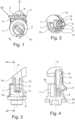
- FIG. 1a three-dimensional view of an adjusting element 1 is shown, wherein the adjusting element 1 is in engagement with a control contour 2, wherein the control contour 2 can be part of a lock housing, for example.
- the adjusting element 1is shown in a first end position of a locking position R1, in which the spring lip 3 is in a relaxed position.
- a thickening 4, which can be described as pointed,protrudes from the control contour 2, so that a first locking position R1 is assumed by the adjusting element 1.
- the Actuator 1can be moved in the direction of arrow P and starting from the Figure 1
- the locking position R1 shown in the illustrationcan be swivelled clockwise so that the actuating element assumes the second locking position R2.
- the locking positions R1, R2are shown in the Figure 1 by the position of an engagement contour 5.
- the locking position R1corresponds, for example, to the functional position "child safety lock engaged", whereas the locking position R2 represents the functional position of the actuating element 1 in which the child safety lock is designed.
- the spring lip 3 or the thickening 4is guided along the control contour 2.
- the control contour 2forms a fixed system and is, for example, part of the lock housing.
- the thickening 4 or the spring lip 3is pivoted into the adjusting element or is bent into the adjusting element 1.
- the maximum pivoting of the spring lip 3takes place in the middle 6 of the control contour 2, whereby the spring lip 3 is pivoted maximally into the adjusting element 1.
- actuating element 1In the Figure 3 a side view of the actuating element 1 is shown. It can be seen that the actuating element 1 can be described as essentially cylindrical and extending along an axis A. It can also be clearly seen that the spring lip 3 extends from a first axial end 14 of the actuating element 1 in the direction of the engagement contour 5, the spring lip 3 having a first region 15 which is made of the same material and has a uniform thickness. This first region 15 can also be described as a spring region 15. The spring region 15 is followed by a continuously thickening region which tapers off almost to a point, so that the spring lip 3 tapers off in a thickening 4. The thickening 4 is provided with a radius at the end, which enables easy sliding on the control contour 2.
- the radius on the thickening 4can be used to easily move the adjusting element, but also to minimize noise during adjustment of the adjusting element 1.
- the support means 9extends from a further axial end 16 of the adjusting element 1 in the direction of the spring lip 3. The spring lip 3 and the support means 9 are thus formed opposite one another on the adjusting element 1.
- FIG 4is a section along the line IV-IV from the Figure 3
- the opposing connection areas 14, 16 for the spring lip 3 and the support means 9 on the actuating element 1can be clearly seen. If the actuating element 1 is now moved from the first locking position R1 to the second locking position R2, the spring lip 3 in the middle 6 of the control contour 2 is pivoted as far as possible into the cavity 8. The pivoting in takes place via a force F, which the housing 17 or the control contour 2 on the housing 17 introduces into the actuating element 1. The force F bends or pivots the spring lip 3 into the cavity 8, whereby the spring lip 3 comes into engagement with the support means 9.
- the position of the spring lip 3 and the support means 9 in the maximum pivoted positionis in the Figure 4 additionally inserted as a dashed line. It can be seen that a rear wall 18 of the cavity 8 offers a stop surface 18 for the support means 9.
- the support means 9thus serves as an abutment for the spring lip 3, whereby the support means itself can be supported on the cavity 8.
- Thisprovides maximum long-term stability of the actuating element 1 and higher spring forces can be achieved on the actuating element 1.
- the inventive structure of the actuating element from spring lip 3 and support means 9thus increases the functional reliability, the spring force and the long-term stability of the actuating element. Consequently, a high level of functional reliability can be achieved even with high-strength plastics, in particular glass fiber reinforced plastics.
Landscapes
- Health & Medical Sciences (AREA)
- Child & Adolescent Psychology (AREA)
- Lock And Its Accessories (AREA)
Description
Translated fromGermanDie Erfindung betrifft eine Kraftfahrzeugschließeinrichtung aufweisend ein Gesperre mit einer Drehfalle und mindestens einer Sperrklinke, einem auf die Sperrklinke wirkenden Betätigungshebelwerk und einer Kindersicherungseinrichtung mit einem Stellelement, wobei das Stellelement in mindestens zwei Positionen verrastbar ist und einem Federelement am Stellelement, wobei das Federelement derart mit einer Steuerkurve zusammenwirkt, dass das Stellelement federbelastet in die Rastposition hinein verstellbar ist.The invention relates to a motor vehicle locking device comprising a locking mechanism with a rotary latch and at least one pawl, an actuating lever mechanism acting on the pawl and a child safety device with an adjusting element, wherein the adjusting element can be locked in at least two positions and a spring element on the adjusting element, wherein the spring element interacts with a control curve in such a way that the adjusting element can be adjusted into the locking position under spring load.
Kraftfahrzeugschließeinrichtungen mit einer integrierten Kindersicherungseinrichtung sind üblicherweise an hinteren Seitentüren bei Kraftfahrzeugen vorgesehen, um in einer Stellung "Kindersicherung Ein" die Türinnengriffe außer Funktion zu setzen. Dagegen lässt sich die fragliche Seitentür nach wie vor von außen öffnen, weil der Außentürgriff unverändert aktiviert bleibt. Die Stellung "Kindersicherung Ein" der Kindersicherungseinrichtung bzw. des Kindersicherungshebels korrespondiert also zu der zuvor bereits angesprochenen selektiven Deaktivierung des Türinnengriffes, welcher als Folge hiervon leer geht und nicht in der Lage ist, ein in der Kraftfahrzeugschließeinrichtung befindliches Gesperre zu öffnen. Demgegenüber korrespondiert die Stellung "Kindersicherung Aus" der Kindersicherungseinrichtung dazu, dass der Innentürgriff aktiviert ist und folglich über das Betätigungshebelwerk die Sperrklinke von der Drehfalle abheben kann. Als Folge hiervon lässt sich die zugehörige Kraftfahrzeug-Seitentür problemlos öffnen, und zwar von innen und außen. Diese Funktionalität hat sich grundsätzlich bewährt und kann natürlich auch auf andere Kraftfahrzeugtüren übertragen und ausgedehnt werden.Motor vehicle locking devices with an integrated child safety device are usually provided on rear side doors of motor vehicles in order to deactivate the inside door handles in a "child safety lock on" position. In contrast, the side door in question can still be opened from the outside because the outside door handle remains activated. The "child safety lock on" position of the child safety device or the child safety lock lever therefore corresponds to the previously mentioned selective deactivation of the inside door handle, which as a result becomes idle and is not able to open a locking mechanism in the motor vehicle locking device. In contrast, the "child safety lock off" position of the child safety device corresponds to the inside door handle being activated and consequently the pawl being able to lift off the rotary latch via the actuating lever mechanism. As a result, the associated motor vehicle side door can be opened without any problem, both from the inside and the outside. This functionality has has proven itself in principle and can of course also be transferred and extended to other vehicle doors.
Um die Kindersicherungseinrichtung von außen manuell einlegen zu können, werden vielfach sogenannte Schaltnüsse eingesetzt, wobei in dieser Schaltnuss zum Beispiel ein Schlüssel einführbar ist und die Kindersicherung ein- bzw. auslegbar ist. Zumeist wird dazu die Schaltnuss verschwenkt. Um die Endlagen der Kindersicherung sicher einnehmen zu können, ist aus der
Ein weiteres Stellelement einer Kindersicherungseinrichtung ist aus der
Zum weiteren Stand der Technik gehört noch ein Schließsystem, insbesondere ein Türschloss, wie es im Rahmen der
Die bekannten Ausgestaltungen der Kindersicherungseinrichtungen haben sich grundsätzlich bewährt, stoßen aber dann an ihre Grenzen, wenn in Bezug auf eine Dauerstabilität hohe Anforderungen, das heißt hohe Stellkräfte, für die Kindersicherungseinrichtungen gefordert werden. Insbesondere in diesen Fällen werden Kunststoffe eingesetzt, die eine höhere Festigkeit und/oder Zähigkeit aufweisen, was in Bezug auf eine Dauerelastizität wiederum eine konstruktive Herausforderung darstellt. Hier setzt die Erfindung ein.The known designs of child safety devices have generally proven themselves, but reach their limits when high demands are placed on the child safety devices in terms of long-term stability, i.e. high actuating forces. In these cases in particular, plastics are used that have a higher strength and/or toughness, which in turn represents a design challenge in terms of long-term elasticity. This is where the invention comes in.
Aufgabe der Erfindung ist es, eine Kindersicherungseinrichtung bereitzustellen, die auch bei unelastischeren Werkstoffen und höheren Federkräften ein sicheres und insbesondere ein dauerstabiles Erreichen der Rastpositionen ermöglicht. Darüber hinaus ist es Aufgabe der Erfindung, eine konstruktiv einfache und kostengünstige und somit insgesamt verbesserte Kindersicherungseinrichtung für eine Kraftfahrzeugschließeinrichtung bereitzustellen.The object of the invention is to provide a child safety device that enables the locking positions to be reached safely and, in particular, with long-term stability, even with less elastic materials and higher spring forces. In addition, the object of the invention is to provide a structurally simple and cost-effective and thus overall improved child safety device for a motor vehicle locking device.
Die Lösung der Aufgabe erfolgt erfindungsgemäß durch die Merkmale des unabhängigen Patentanspruchs 1. Vorteilhafte Ausgestaltungen der Erfindung sind in den Unteransprüchen angegeben. Es wird darauf hingewiesen, dass die im Folgenden beschriebenen Ausführungsbeispiele nicht beschränkend sind, es sind vielmehr beliebige Variationsmöglichkeiten der in der Beschreibung, den Unteransprüchen und den Zeichnungen beschriebenen Merkmale möglich.The object is achieved according to the invention by the features of
Die Kraftfahrzeugschließeinrichtung weist auf: ein Gesperre mit einer Drehfalle und mindestens einer Sperrklinke, einem auf die Sperrklinke wirkenden Betätigungshebelwerk und einer Kindersicherungseinrichtung mit einem Stellelement, wobei das Stellelement in mindestens zwei Positionen verrastbar ist und einem Federelement am Stellelement, wobei das Federelement derart mit einer Steuerkurve zusammenwirkt, dass das Stellelement federbelastet in die Rastpositionen hinein verstellbar ist, und wobei das Federelement als Federlippe ausgebildet ist. Durch den erfindungsgemäßen Aufbau der Kindersicherungseinrichtung ist nun die Möglichkeit geschaffen, auch unelastische Werkstoffe, das heißt zum Beispiel Kunststoffe mit einem Glasfaseranteil, im Bereich der Kindersicherungseinrichtung einzusetzen. Durch den Glasfaseranteil im Kunststoff steigt die Widerstandskraft der Federlippe, wodurch die Rastpositionen sicher und dauerstabil erreichbar sind.The motor vehicle locking device has: a locking mechanism with a rotary latch and at least one pawl, an actuating lever mechanism acting on the pawl and a child safety device with an adjusting element, wherein the adjusting element can be locked in at least two positions and a spring element on the adjusting element, wherein the spring element interacts with a control curve in such a way that the adjusting element can be adjusted into the locking positions under spring load, and wherein the spring element is designed as a spring lip. The inventive design of the child safety device now makes it possible to use inelastic materials, for example plastics with a glass fiber content, in the area of the child safety device. The glass fiber content in the plastic increases the resistance of the spring lip, whereby the locking positions can be reached safely and with long-term stability.
Die Federlippe erstreckt sich ausgehend vom Stellelement in Richtung einer Steuerkontur, wobei in einer vorteilhaften Ausgestaltungsvariante die Federlippe eine Verdickung aufweist, die mit der Steuerkontur in Eingriff bringbar ist. Dabei weist die Federlippe zumindest eine längliche Erstreckung auf, die sich ausgehend vom Stellelement zumindest bereichsweise entlang des Stellelements erstreckt, so dass ein ausreichender Federweg für die Federlippe erzielbar ist.The spring lip extends from the actuating element in the direction of a control contour, wherein in an advantageous embodiment the spring lip has a thickening that can be brought into engagement with the control contour. The spring lip has at least one elongated extension that extends from the actuating element at least in some areas along the actuating element, so that sufficient spring travel can be achieved for the spring lip.
Je nach Zähigkeit bzw. Festigkeit des eingesetzten Kunststoffes kann die Erstreckung der Federlippe entlang des Stellelements und bevorzug entlang einer axialen Erstreckung des Stellelements unterschiedliche Längen aufweisen. Mittels der Verdickung, die insbesondere eine Federnase sein kann, wird zusätzlich eine Sicherungsmaßnahme in die Kindersicherung integriert. Somit muss nicht allein die Federlippe mit der Steuerkontur zusammenarbeiten, sondern es besteht die Möglichkeit, die Verdickung derart auszubilden, dass ein sicherer Formschluss in den Rastpositionen im Zusammenspiel mit der Steuerkontur erzielbar ist. Vorzugsweise weist die Verdickung eine konische Form auf, wobei sich die Verdickung ausgehend von der Federlippe in Richtung der Steuerkontur verjüngt, mit anderen Worten ist die Verdickung an der Federlippe konisch in Richtung der Steuerkontur ausbildbar.Depending on the toughness or strength of the plastic used, the extension of the spring lip along the actuating element and preferably along an axial extension of the actuating element have different lengths. By means of the thickening, which can in particular be a spring nose, an additional safety measure is integrated into the child safety lock. This means that not only the spring lip has to work together with the control contour, but it is also possible to design the thickening in such a way that a secure form fit can be achieved in the locking positions in interaction with the control contour. The thickening preferably has a conical shape, with the thickening tapering from the spring lip towards the control contour, in other words the thickening on the spring lip can be designed conically in the direction of the control contour.
In einer weiteren Ausgestaltungsvariante der Erfindung ist die Federlippe in das Stellelement hinein verschwenkbar. Durch die Ausbildung des Stellelements in der Form, dass die Federlippe in ein Inneres des Stellelements hinein verschwenkbar ist, wird der benötigte Bauraum für die Kindersicherungseinrichtung verringert. Gleichzeitig ist der Federweg für die Federlippe durch die Öffnung bzw. den Hohlraum im Stellelement begrenzbar. Der Hohlraum kann somit ein Stützmittel für die Federlippe bereitstellen. In vorteilhafter Weise kann durch das Hineinschwenken der Federlippe aber der Bauraum zur Realisierung eines Stellelements im Zusammenspiel mit einer Steuerkontur verringert werden.In a further embodiment of the invention, the spring lip can be pivoted into the actuating element. By designing the actuating element in such a way that the spring lip can be pivoted into the interior of the actuating element, the installation space required for the child safety device is reduced. At the same time, the spring travel for the spring lip can be limited by the opening or the cavity in the actuating element. The cavity can thus provide a support for the spring lip. However, by pivoting the spring lip in, the installation space for implementing an actuating element in conjunction with a control contour can advantageously be reduced.
Wird im Sinne der Erfindung von einer Steuerkontur gesprochen, so kann die Steuerkontur zum Beispiel durch einen entsprechend konturierten Bereich eines Gehäuses der Schließeinrichtung bereitgestellt werden. Das Stellelement wirkt dann mit der Kontur bzw. Steuerkontur am Gehäuse zusammen. In vorteilhafter Weise sind Steuerkontur und Federlippe derart ausgebildet, dass ein sicheres Erreichen der Endlagen bzw. Rastpositionen des Stellelements einnehmbar sind und gleichzeitig kann die Steuerkontur derart ausgebildet sein, dass ein Verharren des Stellelements in einer Mittenposition verhinderbar ist. Beispielsweise kann dazu die Steuerkontur eine Spitze in der Mitte in Richtung des Stellelements aufweisen, die mit einer verjüngten oder spitzen Kontur an der Federlippe zusammenwirkt, so dass das Stellelement in einer Mittenstellung in einer indifferenten, das heißt unstabilen Lage vorliegt. In jedem Fall wird das Stellelement durch die geometrische Form der Konturen der Steuerkontur und der Federlippe in eine der beiden Rastpositionen hinein verschwenken. Eine undefinierte Zwischenposition am Stellelement wird durch die spitze Kontur wirkungsvoll verhindert.If, in the sense of the invention, a control contour is referred to, the control contour can be provided, for example, by a correspondingly contoured area of a housing of the locking device. The actuating element then interacts with the contour or control contour on the housing. The control contour and spring lip are advantageously designed in such a way that that the end positions or locking positions of the actuating element can be reached safely and at the same time the control contour can be designed in such a way that the actuating element can be prevented from remaining in a middle position. For example, the control contour can have a tip in the middle in the direction of the actuating element, which interacts with a tapered or pointed contour on the spring lip, so that the actuating element is in an indifferent, i.e. unstable, position in a middle position. In any case, the actuating element will pivot into one of the two locking positions due to the geometric shape of the contours of the control contour and the spring lip. An undefined intermediate position on the actuating element is effectively prevented by the pointed contour.
Erfindungsgemäß ist ein Stützmittel vorgesehen, wobei das Stützmittel zumindest während eines Verstellens des Stellelements mit dem Stellelement in Eingriff bringbar ist. Ein Stützmittel kann beispielsweise eine Rückwand einer Vertiefung bzw. eines Hohlraums oder einer Ausnehmung im Stellelement sein. Hierbei wird die Federlippe durch die Bewegung und das Zusammenspiel mit der Steuerkontur in das Stellelement hinein verbogen und legt sich an der Rückwand bzw. der inneren Öffnung des Stellelements an. Hierdurch erfährt die Federlippe eine Unterstützung, die eine Dauerstabilität der Federlippe ermöglicht. Dabei ist das Stützmittel derart weit von der Federlippe beabstandet, dass einerseits ein Stützen der Federlippe ermöglichbar ist und andererseits ein Überfahren der Steuerkontur in jeder Weise gewährleistet bleibt. Die Federlippe wird dabei elastisch verformt, ohne eine plastische Verformung zu erfahren. Somit ist eine hohe Funktionssicherheit der Kindersicherung gegeben, die auch dauerstabil einsetzbar ist.According to the invention, a support means is provided, wherein the support means can be brought into engagement with the actuating element at least during adjustment of the actuating element. A support means can be, for example, a rear wall of a depression or a cavity or a recess in the actuating element. In this case, the spring lip is bent into the actuating element by the movement and the interaction with the control contour and rests against the rear wall or the inner opening of the actuating element. This provides the spring lip with support, which enables the spring lip to be permanently stable. The support means is spaced far enough from the spring lip that, on the one hand, the spring lip can be supported and, on the other hand, the control contour can be passed over in every way. The spring lip is elastically deformed without undergoing plastic deformation. This means The child safety lock has a high level of functional reliability and can also be used permanently.
Eine weitere Ausgestaltungsvariante der Erfindung ergibt sich dann, wenn das Stützmittel sich in einem Hohlraum, insbesondere eine Ausnehmung, des Stellelements hinein erstreckt. Die Ausbildung eines separaten Stützmittels am Stellelement bietet einen weiteren Vorteil, nämlich den, dass das separate Stützmittel ebenfalls bewegbar bzw. verschwenkbar ist. Wird die Federlippe beim Verschwenken bzw. Verdrehen des Stellmittels in das Stellmittel hinein bewegt, so gelangt die Federlippe in Eingriff mit dem Stützmittel, wobei sich das Stützmittel bei einem weiteren Hineinbewegen der Federlippe ebenfalls verbiegt und somit ein elastisches Widerlager für die Federlippe bildet. Das Stellmittel weist folglich in dieser Ausführungsform zwei Federelemente auf, die interagieren und sich gegenseitig stützen. In vorteilhafter Weise erstreckt sich das Stützmittel in den Hohlraum des Stellmittels hinein und kann beispielsweise sich als zylindrischer oder ovaler Stift in den Hohlraum hinein erstrecken. Bei der Erstreckung reicht das Stützmittel zumindest so weit in den Hohlraum hinein, dass ein Zusammenspiel von Federlippe und Stützmittel ermöglichbar ist. In vorteilhafter Weise sind die Federlippe und das Stützmittel gegenüberliegend am Stellmittel angeordnet.A further embodiment of the invention arises when the support means extends into a cavity, in particular a recess, of the actuating element. The formation of a separate support means on the actuating element offers a further advantage, namely that the separate support means is also movable or pivotable. If the spring lip is moved into the actuating means when pivoting or twisting the actuating means, the spring lip engages with the support means, whereby the support means also bends when the spring lip is moved further in and thus forms an elastic abutment for the spring lip. In this embodiment, the actuating means therefore has two spring elements that interact and support each other. The support means advantageously extends into the cavity of the actuating means and can, for example, extend into the cavity as a cylindrical or oval pin. When extended, the support means reaches at least far enough into the cavity to enable the spring lip and support means to interact. Advantageously, the spring lip and the support means are arranged opposite one another on the adjusting means.
Weist das Stellmittel eine insgesamt zylindrische Form auf, wobei sich das Stellelement entlang einer Mittelachse erstreckt, so kann die Federlippe an einem axialen Ende am Stellelement angeordnet sein, wohingegen das Stützmittel sich ausgehend von einem gegenüberliegenden axialen Ende des Stellmittels in Richtung der Federlippe erstreckt. Durch das Zusammenspiel von Federlippe und Stützmittel wird die auf die Federlippe wirkende Kraft aufgeteilt, insbesondere auf die sich gegenüberliegenden Seiten des Stellelements aufgeteilt, wodurch einerseits die Gegenkraft auf die Steuerkontur und somit die benötigte Kraft zum Bewegen des Stellmittels einstellbar ist und gleichzeitig kann durch die Lastverteilung eine Dauerstabilität des Stellelements gesteigert bzw. gewährleistet werden.If the adjusting means has a generally cylindrical shape, with the adjusting element extending along a central axis, the spring lip can be arranged at one axial end on the adjusting element, whereas the support means extends from an opposite axial end of the adjusting means in the direction of the spring lip. The interaction of the spring lip and the support means determines the force applied to the spring lip. acting force is divided, in particular, between the opposite sides of the actuating element, whereby on the one hand the counterforce on the control contour and thus the force required to move the actuating means can be adjusted and at the same time the long-term stability of the actuating element can be increased or ensured through the load distribution.
Ist das Stützmittel mittels der Federlippe bis zur Anlage des Stützmittels an das Stellmittel verschwenkbar, so ergibt sich eine weitere vorteilhafte Ausführungsform der Erfindung. Die der Steuerkontur entgegenstehende Kraft kann durch ein Anliegen des Stützmittels am Stellelement eine weitere Kraft entgegenstehen. Durch das Anliegen kann auch ein Anschlag für die Federlippe bereitgestellt werden, wodurch eine übermäßige Verformung der Federlippe verhinderbar ist. Federlippe und Stützmittel wirken dabei zusammen und ergänzen sich dahingehend, dass das Stützmittel zur Erhöhung der Federkraft des Stellelements dient.If the support means can be pivoted by means of the spring lip until the support means rests on the actuating means, this results in a further advantageous embodiment of the invention. The force opposing the control contour can be opposed by a further force if the support means rests on the actuating element. This rest can also provide a stop for the spring lip, which can prevent excessive deformation of the spring lip. The spring lip and support means work together and complement each other in such a way that the support means serves to increase the spring force of the actuating element.
Eine weitere Ausgestaltungsvariante der Erfindung wird dann erzielt, wenn das Stellmittel aus Kunststoff und einstückig mit der Federlippe, der Verdickung und dem Stützmittel ausgebildet ist. Das Stellelement ist bevorzugt ein Kunststoff-Spritzgussbauteil und wird einstückig hergestellt. Kommen üblicherweise Werkstoffe wie Polybutylenterephthalat (PBT) oder Polyamid (PA) zum Einsatz, so ist es ebenfalls vorstellbar, Kunststoffe mit einem Glasfaseranteil einzusetzen. Kunststoffe mit einem Glasfaseranteil bieten den Vorteil, dass höhere Gegenkräfte gegen die Steuerkontur erzielbar sind. Gleichzeitig aber nimmt der Erhöhung des Glasfaseranteils die Elastizität des Werkstoffs ab, wodurch wiederum der Federweg der Federlippe bzw. des Stützmittels reduziert wird. Je länger der Federweg, desto höher ist die Gefahr, eines Federbruchs. Reicht die mittels des Stellmittels erzeugte Kraft nicht aus, um die geforderten Stellkräfte am Stellelement bereitzustellen, muss der Federweg erhöht werden. Eine Erhöhung des Federwegs birgt wiederum die Gefahr eines Federbruchs. Durch den Einsatz des Stützmittels für die Federlippe kann der Federlippe ein zusätzliches Stützmoment entgegengebracht werden, wodurch die Gefahr eines Federbruchs minimiert wird. Versuche haben gezeigt, dass das erzeugte Moment an der Federlippe mit dem Einsatz eines Stützmittels signifikant gesteigert werden konnte, wobei eine ca. 25 % höhere Federkraft durch die Federlippe erzielbar ist. Werden beispielsweise die Momente an der Federlippe erfasst, während die Federlippe mit der Steuerkontur in Eingriff ist, so können Momente ohne Stützmittel von ca. 30-35 Nm, wohingegen bei einem Einsatz des Stützmittels ein Moment von ca. 45 Nm am Stützmittel messbar sind. Durch den Einsatz des Stützmittels kann folglich die Federkraft der Federlippe in Bezug auf die Steuerkontur signifikant gesteigert werden.A further embodiment of the invention is achieved when the adjusting means is made of plastic and is formed in one piece with the spring lip, the thickening and the support means. The adjusting element is preferably a plastic injection-molded component and is manufactured in one piece. If materials such as polybutylene terephthalate (PBT) or polyamide (PA) are usually used, it is also conceivable to use plastics with a glass fiber content. Plastics with a glass fiber content offer the advantage that higher counterforces against the control contour can be achieved. At the same time, however, the elasticity of the material decreases as the glass fiber content increases, which in turn reduces the spring travel of the spring lip. or the support means is reduced. The longer the spring travel, the higher the risk of spring breakage. If the force generated by the actuating means is not sufficient to provide the required actuating forces on the actuating element, the spring travel must be increased. Increasing the spring travel, in turn, carries the risk of spring breakage. By using the support means for the spring lip, the spring lip can be provided with an additional support moment, which minimizes the risk of spring breakage. Tests have shown that the moment generated on the spring lip can be significantly increased with the use of a support means, with an approx. 25% higher spring force being achievable with the spring lip. If, for example, the moments on the spring lip are recorded while the spring lip is in engagement with the control contour, moments of approx. 30-35 Nm can be measured on the support means without a support means, whereas a moment of approx. 45 Nm can be measured when the support means is used. By using the support means, the spring force of the spring lip in relation to the control contour can be significantly increased.
Ist das Stellelement mit einem Stellmittel und insbesondere über eine Eingriffskontur verstellbar, insbesondere verschwenkbar, so ergibt sich eine weitere Ausgestaltungsvariante der Erfindung. Das Stellmittel ist insbesondere ein Stellmittel für eine Kindersicherung, wobei das Stellmittel manuell verstellbar und bevorzugt verschwenkbar im Kraftfahrzeugschloss angeordnet ist. Dabei dient eine Eingriffskontur dazu, um das Stellmittel bevorzugt zu verschwenken und eine Kindersicherung einzulegen bzw. auszulegen. Die Eingriffskontur kann beispielsweise schlitzförmig ausgebildet sein, so dass das Stellmittel mittels eines Schlüsselbunds oder eines Schraubenziehers verstellbar ist. Dabei ist die Eingriffskontur bevorzugt von außen und noch bevorzugter vom Bereich einer Türfalz der geöffneten hinteren Seitentür erreichbar.If the actuating element is adjustable, in particular pivotable, with an actuating means and in particular via an engagement contour, this results in a further embodiment variant of the invention. The actuating means is in particular an actuating means for a child safety lock, wherein the actuating means is arranged in the motor vehicle lock so that it can be adjusted manually and preferably pivoted. An engagement contour serves to preferably pivot the actuating means and to insert or remove a child safety lock. The engagement contour can, for example, be designed in the shape of a slot, so that the actuating means can be opened using a bunch of keys or a screwdriver. is adjustable. The engagement contour is preferably accessible from the outside and even more preferably from the area of a door rebate of the open rear side door.
Weiterhin vorteilhaft kann es sein, wenn das Stellelement eine Betätigungskontur, insbesondere einen Betätigungshebel, aufweist. Das Stellelement dient zur Einlegung der Kindersicherung und wirkt im Kraftfahrzeugschloss beispielsweise mit einer Mechanik für die Innenbetätigung des Kraftfahrzeugschlosses zusammen. Die Innenbetätigung weist dazu einen Innentürgriff auf, der über einen Innenbetätigungshebel bevorzugt einen Auslösehebel betätigt. Mittels des Auslösehebels kann dann das Gesperre entsperrt werden und die Tür geöffnet. Mittels der Kindersicherung wird die Innenbetätigungskette unterbrochen, so dass eine Innenbetätigung, das heißt ein Öffnen des Schlosses, unterbindbar ist. Eine am Stellelement ausgebildete Betätigungskontur kann die Innenbetätigungskette unterbrechen und somit für eine Kindersicherung sorgen. In vorteilhafter Weise ist die Betätigungskontur einstückig mit dem Stellelement ausgebildet und kann beispielsweise als Betätigungshebel ausgebildet sein. In vorteilhafter Weise weist die Betätigungskontur eine Steuerkontur und insbesondere eine exzentrische Steuerkontur auf, so dass ein kontinuierliches Krafteinleiten ein die Betätigungshebelkette ermöglichbar ist.It can also be advantageous if the actuating element has an actuating contour, in particular an actuating lever. The actuating element is used to engage the child safety lock and works together in the motor vehicle lock, for example, with a mechanism for the internal actuation of the motor vehicle lock. The internal actuation has an internal door handle, which preferably actuates a release lever via an internal actuating lever. The locking mechanism can then be unlocked and the door opened using the release lever. The child safety lock interrupts the internal actuating chain so that internal actuation, i.e. opening of the lock, can be prevented. An actuating contour formed on the actuating element can interrupt the internal actuating chain and thus ensure child safety. The actuating contour is advantageously formed in one piece with the actuating element and can be designed, for example, as an actuating lever. Advantageously, the actuating contour has a control contour and in particular an eccentric control contour, so that a continuous introduction of force into the actuating lever chain is possible.
Nachfolgend wird die Erfindung unter Bezugnahme auf die anliegenden Zeichnungen anhand eines bevorzugten Ausführungsbeispiels näher erläutert. Es gilt jedoch der Grundsatz, dass das Ausführungsbeispiel die Erfindung nicht beschränkt, sondern lediglich vorteilhafte Ausgestaltungsformen der Erfindung darstellen. Die dargestellten Merkmale können einzeln oder in Kombination mit weiteren Merkmalen der Beschreibung wie auch den Patentansprüchen einzeln oder in Kombination ausgeführt werden.The invention is explained in more detail below with reference to the attached drawings using a preferred embodiment. However, the principle applies that the embodiment does not limit the invention, but merely represents advantageous embodiments of the invention. The features shown can be used individually or in combination with other features of the description as well as the patent claims individually or in combination.
Es zeigt:
Figur 1- eine dreidimensionale Ansicht auf ein Stellmittel im Eingriff mit einer Steuerkontur und in Ansicht auf eine Eingriffskontur des Stellelements,
Figur 2- eine dreidimensionale Ansicht auf das Stellelement aus Richtung des Pfeils II aus der
Figur 1 Figur 3- eine Ansicht auf das Stellelement gemäß der
Figur 1 aus Richtung des Pfeils III, wobei das Stellelement in seiner axialen Erstreckung und in einer Seitenansicht wiedergegeben ist, und Figur 4- einen Schnitt durch das Stellelement entlang der Linie IV-
IV aus Figur 3 mit einer zusätzlichen Wiedergabe einer betätigten Federlippe bzw. eines Stützmittels.
- Figure 1
- a three-dimensional view of an actuating means in engagement with a control contour and in view of an engagement contour of the actuating element,
- Figure 2
- a three-dimensional view of the actuator from the direction of arrow II from the
Figure 1 , where a view of the cavity in the actuating element with the support means arranged in the cavity can be seen, - Figure 3
- a view of the actuator according to the
Figure 1 from the direction of arrow III, wherein the adjusting element is shown in its axial extension and in a side view, and - Figure 4
- a section through the actuator along the line IV-IV
Figure 3 with an additional representation of an actuated spring lip or a support means.
In der
Beim Verschwenken des Stellelements 1 wird die Federlippe 3 bzw. die Verdickung 4 entlang der Steuerkontur 2 geführt. Die Steuerkontur 2 bildet eine feste Anlage und ist beispielsweise Teil des Schlossgehäuses. Während des Verschwenkens des Stellelements 1 im Uhrzeigersinn wird die Verdickung 4 bzw. die Federlippe 3 in das Stellelement hinein verschwenkt bzw. in das Stellelement 1 hinein verbogen. Die maximale Verschwenkung der Federlippe 3 erfolgt in der Mitte 6 der Steuerkontur 2, wobei die Federlippe 3 maximal in das Stellelement 1 hinein verschwenkt wird.When the adjusting
In der
In der
In der
Die Stellung der Federlippe 3 und des Stützmittels 9 in der maximal verschwenkten Position ist in der
- 11
- Stellelementactuator
- 22
- Steuerkonturcontrol contour
- 33
- Federlippespring lip
- 44
- Verdickungthickening
- 55
- Eingriffskonturengagement contour
- 66
- Mitte der Steuerkonturcenter of the control contour
- 77
- Betätigungskonturactuation contour
- 88
- Hohlraumcavity
- 99
- Stützmittelproppant
- 1010
- Führungsflächeguide surface
- 1111
- Aussparungrecess
- 1212
- Randedge
- 1313
- Anschlagstop
- 14, 1614, 16
- axiales Endeaxial end
- 1515
- erster Bereich, Federbereichfirst area, spring area
- 1717
- GehäuseHousing
- 1818
- Wand, Anschlagflächewall, stop surface
- R1, R2R1, R2
- Rastpositionlocking position
- PP
- PfeilArrow
- AA
- Achseaxis
- FF
- KraftPower
Claims (9)
- A motor vehicle locking device comprising a locking mechanism having a catch and at least one pawl, an operating lever mechanism acting on the pawl and a child safety device having an adjustment mechanism (1), wherein the adjustment mechanism (1) is latchable in at least two latching positions (R1, R2), and a spring element (3) on the adjustment mechanism (1), wherein the spring element (3) interacts with a control cam (2) in such a way that the adjustment mechanism (1) can be adjusted in a spring-loaded manner into the latching positions (R1, R2), wherein the spring element (3) is designed as a spring lip (3),characterized in that
a support means (9) is provided, wherein the support means (9) can be brought into engagement with the adjustment mechanism (1) at least during an adjustment of the adjustment mechanism (1). - The motor vehicle locking device according to claim 1,characterized in that the spring lip (3) has a thickened portion (4), in particular a spring tab.
- The motor vehicle locking device according to either claim 1 or claim 2,characterized in that the spring lip (3) is pivotable into the adjustment mechanism (1).
- The motor vehicle locking device according to any of claims 1 to 3,characterized in that the support means (9) extends into a cavity (8), in particular a recess, of the adjustment mechanism (1).
- The motor vehicle locking device according to any of claims 1 to 4,characterized in that the support means (9) is pivotable by means of the spring lip (3) until the support means (9) abuts the adjusting means (1), in particular a stop surface (18) of the adjustment mechanism.
- The motor vehicle locking device according to any of claims 1 to 5,characterized in that the adjustment mechanism (1) is made of plastics material and is designed in one piece with the spring lip (3), the thickened portion (4) and the support means (9).
- The motor vehicle locking device according to any of claims 1 to 6,characterized in that the spring lip (3) and the support means (9) are formed opposite one another on the adjustment mechanism (1).
- The motor vehicle locking device according to any of claims 1 to 7,characterized in that the adjustment mechanism (1) is adjustable, in particular pivotable, using an adjusting means (5) and in particular via an engagement contour (5).
- The motor vehicle locking device according to any of claims 1 to 8,characterized in that the adjustment mechanism (1) has an operating contour (7), in particular an operating lever.
Applications Claiming Priority (2)
| Application Number | Priority Date | Filing Date | Title |
|---|---|---|---|
| DE102019119256.0ADE102019119256A1 (en) | 2019-07-16 | 2019-07-16 | MOTOR VEHICLE LOCKING DEVICE |
| PCT/DE2020/100567WO2021008651A1 (en) | 2019-07-16 | 2020-06-30 | Motor vehicle locking device |
Publications (2)
| Publication Number | Publication Date |
|---|---|
| EP3999701A1 EP3999701A1 (en) | 2022-05-25 |
| EP3999701B1true EP3999701B1 (en) | 2024-12-18 |
Family
ID=71607670
Family Applications (1)
| Application Number | Title | Priority Date | Filing Date |
|---|---|---|---|
| EP20739845.4AActiveEP3999701B1 (en) | 2019-07-16 | 2020-06-30 | Motor vehicle locking device |
Country Status (4)
| Country | Link |
|---|---|
| US (1) | US12276138B2 (en) |
| EP (1) | EP3999701B1 (en) |
| DE (1) | DE102019119256A1 (en) |
| WO (1) | WO2021008651A1 (en) |
Families Citing this family (1)
| Publication number | Priority date | Publication date | Assignee | Title |
|---|---|---|---|---|
| DE102020103378A1 (en) | 2020-02-11 | 2021-08-12 | Kiekert Aktiengesellschaft | Motor vehicle locking device |
Family Cites Families (6)
| Publication number | Priority date | Publication date | Assignee | Title |
|---|---|---|---|---|
| JP4342502B2 (en) | 2004-11-17 | 2009-10-14 | アイシン精機株式会社 | Door lock child protector device |
| DE102007055413B4 (en)* | 2007-11-19 | 2017-06-22 | Kiekert Ag | Locking system with multi-stable component-spring element device |
| DE102014114347A1 (en)* | 2014-10-02 | 2016-04-07 | Kiekert Ag | Motor vehicle door lock |
| DE102017102815A1 (en) | 2017-02-13 | 2018-08-16 | Kiekert Ag | Motor vehicle door lock |
| DE102017111704A1 (en)* | 2017-05-30 | 2018-12-06 | Kiekert Ag | Locking system with rotatable actuator and spring element |
| US11280116B2 (en)* | 2018-05-15 | 2022-03-22 | Magna Closures Inc. | Closure latch assembly with child lock having asymmetrical toggle spring arrangement |
- 2019
- 2019-07-16DEDE102019119256.0Apatent/DE102019119256A1/enactivePending
- 2020
- 2020-06-30USUS17/625,865patent/US12276138B2/enactiveActive
- 2020-06-30WOPCT/DE2020/100567patent/WO2021008651A1/ennot_activeCeased
- 2020-06-30EPEP20739845.4Apatent/EP3999701B1/enactiveActive
Also Published As
| Publication number | Publication date |
|---|---|
| EP3999701A1 (en) | 2022-05-25 |
| US20220259896A1 (en) | 2022-08-18 |
| US12276138B2 (en) | 2025-04-15 |
| WO2021008651A1 (en) | 2021-01-21 |
| DE102019119256A1 (en) | 2021-01-21 |
Similar Documents
| Publication | Publication Date | Title |
|---|---|---|
| EP2342405B1 (en) | Motor vehicle lock | |
| DE60109146T2 (en) | DOOR LOCKING DEVICE FOR AN ELECTRIC HOUSEHOLD UNIT | |
| DE2854528C2 (en) | ||
| EP2007553B1 (en) | Self-opening tool | |
| EP3199736B1 (en) | Stop damper | |
| DE102006024819A1 (en) | chuck | |
| WO2018202504A1 (en) | Connection terminal | |
| DE4005369C2 (en) | Locking device on a vehicle door | |
| DE102017216920A1 (en) | Door handle device for a door of a motor vehicle, door, motor vehicle | |
| EP3999701B1 (en) | Motor vehicle locking device | |
| DE202006018744U1 (en) | Device for a motor vehicle lock comprises a recess for a locking pin that has an opening region and an end region with a damping element absorbing a contact force from the locking pin and having a guide section forming part of the recess | |
| EP3507508B1 (en) | Rotary closure for connecting components | |
| DE102009009139A1 (en) | Middle armrest for motor vehicle, has bearing block fixed relative to vehicle center console and support body displaceably guided along longitudinal direction on bearing block | |
| DE202016102553U1 (en) | Motor vehicle lock arrangement | |
| EP2393097A1 (en) | Switch with self-adjusting switch plunger guide | |
| WO2016020291A1 (en) | Locking mechanism and longitudinal adjuster with a locking mechanism | |
| EP3841265B1 (en) | Motor vehicle lock, in particular an electrically actuatable motor vehicle lock | |
| WO2018145693A1 (en) | Motor vehicle door lock | |
| DE102013216054B4 (en) | Locking unit for a vehicle seat and vehicle seat | |
| DE202007017096U1 (en) | Motor vehicle parking brake | |
| DE10154692B4 (en) | Locking pin with push-button actuated axial lock | |
| DE10013697A1 (en) | Door window check uses latching system composed of odd-sized teeth on support rod end co-operating with latches during casement movement. | |
| EP4155491B1 (en) | Locking device, in particular for a caravan or mobile home | |
| EP3819449A1 (en) | Motor vehicle lock | |
| WO2020193589A1 (en) | Locking device for a flap element, locking assembly, and motor vehicle |
Legal Events
| Date | Code | Title | Description |
|---|---|---|---|
| STAA | Information on the status of an ep patent application or granted ep patent | Free format text:STATUS: UNKNOWN | |
| STAA | Information on the status of an ep patent application or granted ep patent | Free format text:STATUS: THE INTERNATIONAL PUBLICATION HAS BEEN MADE | |
| PUAI | Public reference made under article 153(3) epc to a published international application that has entered the european phase | Free format text:ORIGINAL CODE: 0009012 | |
| STAA | Information on the status of an ep patent application or granted ep patent | Free format text:STATUS: REQUEST FOR EXAMINATION WAS MADE | |
| 17P | Request for examination filed | Effective date:20220210 | |
| AK | Designated contracting states | Kind code of ref document:A1 Designated state(s):AL AT BE BG CH CY CZ DE DK EE ES FI FR GB GR HR HU IE IS IT LI LT LU LV MC MK MT NL NO PL PT RO RS SE SI SK SM TR | |
| DAV | Request for validation of the european patent (deleted) | ||
| DAX | Request for extension of the european patent (deleted) | ||
| GRAP | Despatch of communication of intention to grant a patent | Free format text:ORIGINAL CODE: EPIDOSNIGR1 | |
| STAA | Information on the status of an ep patent application or granted ep patent | Free format text:STATUS: GRANT OF PATENT IS INTENDED | |
| INTG | Intention to grant announced | Effective date:20240911 | |
| GRAS | Grant fee paid | Free format text:ORIGINAL CODE: EPIDOSNIGR3 | |
| P01 | Opt-out of the competence of the unified patent court (upc) registered | Free format text:CASE NUMBER: APP_53499/2024 Effective date:20240926 | |
| GRAA | (expected) grant | Free format text:ORIGINAL CODE: 0009210 | |
| STAA | Information on the status of an ep patent application or granted ep patent | Free format text:STATUS: THE PATENT HAS BEEN GRANTED | |
| AK | Designated contracting states | Kind code of ref document:B1 Designated state(s):AL AT BE BG CH CY CZ DE DK EE ES FI FR GB GR HR HU IE IS IT LI LT LU LV MC MK MT NL NO PL PT RO RS SE SI SK SM TR | |
| REG | Reference to a national code | Ref country code:CH Ref legal event code:EP | |
| REG | Reference to a national code | Ref country code:DE Ref legal event code:R096 Ref document number:502020010012 Country of ref document:DE | |
| REG | Reference to a national code | Ref country code:IE Ref legal event code:FG4D Free format text:LANGUAGE OF EP DOCUMENT: GERMAN | |
| REG | Reference to a national code | Ref country code:LT Ref legal event code:MG9D | |
| PG25 | Lapsed in a contracting state [announced via postgrant information from national office to epo] | Ref country code:HR Free format text:LAPSE BECAUSE OF FAILURE TO SUBMIT A TRANSLATION OF THE DESCRIPTION OR TO PAY THE FEE WITHIN THE PRESCRIBED TIME-LIMIT Effective date:20241218 | |
| PG25 | Lapsed in a contracting state [announced via postgrant information from national office to epo] | Ref country code:FI Free format text:LAPSE BECAUSE OF FAILURE TO SUBMIT A TRANSLATION OF THE DESCRIPTION OR TO PAY THE FEE WITHIN THE PRESCRIBED TIME-LIMIT Effective date:20241218 | |
| PG25 | Lapsed in a contracting state [announced via postgrant information from national office to epo] | Ref country code:BG Free format text:LAPSE BECAUSE OF FAILURE TO SUBMIT A TRANSLATION OF THE DESCRIPTION OR TO PAY THE FEE WITHIN THE PRESCRIBED TIME-LIMIT Effective date:20241218 | |
| PG25 | Lapsed in a contracting state [announced via postgrant information from national office to epo] | Ref country code:NO Free format text:LAPSE BECAUSE OF FAILURE TO SUBMIT A TRANSLATION OF THE DESCRIPTION OR TO PAY THE FEE WITHIN THE PRESCRIBED TIME-LIMIT Effective date:20250318 | |
| REG | Reference to a national code | Ref country code:NL Ref legal event code:MP Effective date:20241218 | |
| PG25 | Lapsed in a contracting state [announced via postgrant information from national office to epo] | Ref country code:LV Free format text:LAPSE BECAUSE OF FAILURE TO SUBMIT A TRANSLATION OF THE DESCRIPTION OR TO PAY THE FEE WITHIN THE PRESCRIBED TIME-LIMIT Effective date:20241218 Ref country code:GR Free format text:LAPSE BECAUSE OF FAILURE TO SUBMIT A TRANSLATION OF THE DESCRIPTION OR TO PAY THE FEE WITHIN THE PRESCRIBED TIME-LIMIT Effective date:20250319 | |
| PG25 | Lapsed in a contracting state [announced via postgrant information from national office to epo] | Ref country code:RS Free format text:LAPSE BECAUSE OF FAILURE TO SUBMIT A TRANSLATION OF THE DESCRIPTION OR TO PAY THE FEE WITHIN THE PRESCRIBED TIME-LIMIT Effective date:20250318 | |
| PG25 | Lapsed in a contracting state [announced via postgrant information from national office to epo] | Ref country code:NL Free format text:LAPSE BECAUSE OF FAILURE TO SUBMIT A TRANSLATION OF THE DESCRIPTION OR TO PAY THE FEE WITHIN THE PRESCRIBED TIME-LIMIT Effective date:20241218 | |
| PG25 | Lapsed in a contracting state [announced via postgrant information from national office to epo] | Ref country code:SM Free format text:LAPSE BECAUSE OF FAILURE TO SUBMIT A TRANSLATION OF THE DESCRIPTION OR TO PAY THE FEE WITHIN THE PRESCRIBED TIME-LIMIT Effective date:20241218 | |
| PG25 | Lapsed in a contracting state [announced via postgrant information from national office to epo] | Ref country code:PL Free format text:LAPSE BECAUSE OF FAILURE TO SUBMIT A TRANSLATION OF THE DESCRIPTION OR TO PAY THE FEE WITHIN THE PRESCRIBED TIME-LIMIT Effective date:20241218 | |
| PGFP | Annual fee paid to national office [announced via postgrant information from national office to epo] | Ref country code:DE Payment date:20250618 Year of fee payment:6 | |
| PG25 | Lapsed in a contracting state [announced via postgrant information from national office to epo] | Ref country code:ES Free format text:LAPSE BECAUSE OF FAILURE TO SUBMIT A TRANSLATION OF THE DESCRIPTION OR TO PAY THE FEE WITHIN THE PRESCRIBED TIME-LIMIT Effective date:20241218 | |
| PG25 | Lapsed in a contracting state [announced via postgrant information from national office to epo] | Ref country code:IS Free format text:LAPSE BECAUSE OF FAILURE TO SUBMIT A TRANSLATION OF THE DESCRIPTION OR TO PAY THE FEE WITHIN THE PRESCRIBED TIME-LIMIT Effective date:20250418 | |
| PG25 | Lapsed in a contracting state [announced via postgrant information from national office to epo] | Ref country code:PT Free format text:LAPSE BECAUSE OF FAILURE TO SUBMIT A TRANSLATION OF THE DESCRIPTION OR TO PAY THE FEE WITHIN THE PRESCRIBED TIME-LIMIT Effective date:20250421 | |
| PG25 | Lapsed in a contracting state [announced via postgrant information from national office to epo] | Ref country code:EE Free format text:LAPSE BECAUSE OF FAILURE TO SUBMIT A TRANSLATION OF THE DESCRIPTION OR TO PAY THE FEE WITHIN THE PRESCRIBED TIME-LIMIT Effective date:20241218 | |
| PGFP | Annual fee paid to national office [announced via postgrant information from national office to epo] | Ref country code:FR Payment date:20250618 Year of fee payment:6 | |
| PG25 | Lapsed in a contracting state [announced via postgrant information from national office to epo] | Ref country code:RO Free format text:LAPSE BECAUSE OF FAILURE TO SUBMIT A TRANSLATION OF THE DESCRIPTION OR TO PAY THE FEE WITHIN THE PRESCRIBED TIME-LIMIT Effective date:20241218 | |
| PG25 | Lapsed in a contracting state [announced via postgrant information from national office to epo] | Ref country code:SK Free format text:LAPSE BECAUSE OF FAILURE TO SUBMIT A TRANSLATION OF THE DESCRIPTION OR TO PAY THE FEE WITHIN THE PRESCRIBED TIME-LIMIT Effective date:20241218 | |
| PGFP | Annual fee paid to national office [announced via postgrant information from national office to epo] | Ref country code:CZ Payment date:20250619 Year of fee payment:6 | |
| PG25 | Lapsed in a contracting state [announced via postgrant information from national office to epo] | Ref country code:IT Free format text:LAPSE BECAUSE OF FAILURE TO SUBMIT A TRANSLATION OF THE DESCRIPTION OR TO PAY THE FEE WITHIN THE PRESCRIBED TIME-LIMIT Effective date:20241218 | |
| PG25 | Lapsed in a contracting state [announced via postgrant information from national office to epo] | Ref country code:SE Free format text:LAPSE BECAUSE OF FAILURE TO SUBMIT A TRANSLATION OF THE DESCRIPTION OR TO PAY THE FEE WITHIN THE PRESCRIBED TIME-LIMIT Effective date:20241218 |