EP3992650B1 - Apparatus and method for calculating battery power - Google Patents
Apparatus and method for calculating battery powerDownload PDFInfo
- Publication number
- EP3992650B1 EP3992650B1EP20871542.5AEP20871542AEP3992650B1EP 3992650 B1EP3992650 B1EP 3992650B1EP 20871542 AEP20871542 AEP 20871542AEP 3992650 B1EP3992650 B1EP 3992650B1
- Authority
- EP
- European Patent Office
- Prior art keywords
- battery cell
- battery
- resistance
- temperature
- cell
- Prior art date
- Legal status (The legal status is an assumption and is not a legal conclusion. Google has not performed a legal analysis and makes no representation as to the accuracy of the status listed.)
- Active
Links
Images


Classifications
- G—PHYSICS
- G01—MEASURING; TESTING
- G01R—MEASURING ELECTRIC VARIABLES; MEASURING MAGNETIC VARIABLES
- G01R31/00—Arrangements for testing electric properties; Arrangements for locating electric faults; Arrangements for electrical testing characterised by what is being tested not provided for elsewhere
- G01R31/36—Arrangements for testing, measuring or monitoring the electrical condition of accumulators or electric batteries, e.g. capacity or state of charge [SoC]
- G01R31/3644—Constructional arrangements
- G01R31/3648—Constructional arrangements comprising digital calculation means, e.g. for performing an algorithm
- G—PHYSICS
- G01—MEASURING; TESTING
- G01R—MEASURING ELECTRIC VARIABLES; MEASURING MAGNETIC VARIABLES
- G01R31/00—Arrangements for testing electric properties; Arrangements for locating electric faults; Arrangements for electrical testing characterised by what is being tested not provided for elsewhere
- G01R31/36—Arrangements for testing, measuring or monitoring the electrical condition of accumulators or electric batteries, e.g. capacity or state of charge [SoC]
- G01R31/374—Arrangements for testing, measuring or monitoring the electrical condition of accumulators or electric batteries, e.g. capacity or state of charge [SoC] with means for correcting the measurement for temperature or ageing
- G—PHYSICS
- G01—MEASURING; TESTING
- G01R—MEASURING ELECTRIC VARIABLES; MEASURING MAGNETIC VARIABLES
- G01R31/00—Arrangements for testing electric properties; Arrangements for locating electric faults; Arrangements for electrical testing characterised by what is being tested not provided for elsewhere
- G01R31/36—Arrangements for testing, measuring or monitoring the electrical condition of accumulators or electric batteries, e.g. capacity or state of charge [SoC]
- G01R31/382—Arrangements for monitoring battery or accumulator variables, e.g. SoC
- G—PHYSICS
- G01—MEASURING; TESTING
- G01R—MEASURING ELECTRIC VARIABLES; MEASURING MAGNETIC VARIABLES
- G01R31/00—Arrangements for testing electric properties; Arrangements for locating electric faults; Arrangements for electrical testing characterised by what is being tested not provided for elsewhere
- G01R31/36—Arrangements for testing, measuring or monitoring the electrical condition of accumulators or electric batteries, e.g. capacity or state of charge [SoC]
- G01R31/389—Measuring internal impedance, internal conductance or related variables
- G—PHYSICS
- G01—MEASURING; TESTING
- G01R—MEASURING ELECTRIC VARIABLES; MEASURING MAGNETIC VARIABLES
- G01R31/00—Arrangements for testing electric properties; Arrangements for locating electric faults; Arrangements for electrical testing characterised by what is being tested not provided for elsewhere
- G01R31/36—Arrangements for testing, measuring or monitoring the electrical condition of accumulators or electric batteries, e.g. capacity or state of charge [SoC]
- G01R31/396—Acquisition or processing of data for testing or for monitoring individual cells or groups of cells within a battery
- H—ELECTRICITY
- H01—ELECTRIC ELEMENTS
- H01M—PROCESSES OR MEANS, e.g. BATTERIES, FOR THE DIRECT CONVERSION OF CHEMICAL ENERGY INTO ELECTRICAL ENERGY
- H01M10/00—Secondary cells; Manufacture thereof
- H01M10/42—Methods or arrangements for servicing or maintenance of secondary cells or secondary half-cells
- H01M10/425—Structural combination with electronic components, e.g. electronic circuits integrated to the outside of the casing
- H—ELECTRICITY
- H01—ELECTRIC ELEMENTS
- H01M—PROCESSES OR MEANS, e.g. BATTERIES, FOR THE DIRECT CONVERSION OF CHEMICAL ENERGY INTO ELECTRICAL ENERGY
- H01M10/00—Secondary cells; Manufacture thereof
- H01M10/42—Methods or arrangements for servicing or maintenance of secondary cells or secondary half-cells
- H01M10/44—Methods for charging or discharging
- H01M10/441—Methods for charging or discharging for several batteries or cells simultaneously or sequentially
- H—ELECTRICITY
- H01—ELECTRIC ELEMENTS
- H01M—PROCESSES OR MEANS, e.g. BATTERIES, FOR THE DIRECT CONVERSION OF CHEMICAL ENERGY INTO ELECTRICAL ENERGY
- H01M10/00—Secondary cells; Manufacture thereof
- H01M10/42—Methods or arrangements for servicing or maintenance of secondary cells or secondary half-cells
- H01M10/44—Methods for charging or discharging
- H01M10/443—Methods for charging or discharging in response to temperature
- H—ELECTRICITY
- H01—ELECTRIC ELEMENTS
- H01M—PROCESSES OR MEANS, e.g. BATTERIES, FOR THE DIRECT CONVERSION OF CHEMICAL ENERGY INTO ELECTRICAL ENERGY
- H01M10/00—Secondary cells; Manufacture thereof
- H01M10/42—Methods or arrangements for servicing or maintenance of secondary cells or secondary half-cells
- H01M10/48—Accumulators combined with arrangements for measuring, testing or indicating the condition of cells, e.g. the level or density of the electrolyte
- H01M10/482—Accumulators combined with arrangements for measuring, testing or indicating the condition of cells, e.g. the level or density of the electrolyte for several batteries or cells simultaneously or sequentially
- H—ELECTRICITY
- H01—ELECTRIC ELEMENTS
- H01M—PROCESSES OR MEANS, e.g. BATTERIES, FOR THE DIRECT CONVERSION OF CHEMICAL ENERGY INTO ELECTRICAL ENERGY
- H01M10/00—Secondary cells; Manufacture thereof
- H01M10/42—Methods or arrangements for servicing or maintenance of secondary cells or secondary half-cells
- H01M10/48—Accumulators combined with arrangements for measuring, testing or indicating the condition of cells, e.g. the level or density of the electrolyte
- H01M10/486—Accumulators combined with arrangements for measuring, testing or indicating the condition of cells, e.g. the level or density of the electrolyte for measuring temperature
- H—ELECTRICITY
- H01—ELECTRIC ELEMENTS
- H01M—PROCESSES OR MEANS, e.g. BATTERIES, FOR THE DIRECT CONVERSION OF CHEMICAL ENERGY INTO ELECTRICAL ENERGY
- H01M10/00—Secondary cells; Manufacture thereof
- H01M10/60—Heating or cooling; Temperature control
- H01M10/61—Types of temperature control
- H01M10/613—Cooling or keeping cold
- H—ELECTRICITY
- H01—ELECTRIC ELEMENTS
- H01M—PROCESSES OR MEANS, e.g. BATTERIES, FOR THE DIRECT CONVERSION OF CHEMICAL ENERGY INTO ELECTRICAL ENERGY
- H01M10/00—Secondary cells; Manufacture thereof
- H01M10/60—Heating or cooling; Temperature control
- H01M10/62—Heating or cooling; Temperature control specially adapted for specific applications
- H01M10/625—Vehicles
- H—ELECTRICITY
- H01—ELECTRIC ELEMENTS
- H01M—PROCESSES OR MEANS, e.g. BATTERIES, FOR THE DIRECT CONVERSION OF CHEMICAL ENERGY INTO ELECTRICAL ENERGY
- H01M10/00—Secondary cells; Manufacture thereof
- H01M10/60—Heating or cooling; Temperature control
- H01M10/63—Control systems
- H01M10/633—Control systems characterised by algorithms, flow charts, software details or the like
- H—ELECTRICITY
- H01—ELECTRIC ELEMENTS
- H01M—PROCESSES OR MEANS, e.g. BATTERIES, FOR THE DIRECT CONVERSION OF CHEMICAL ENERGY INTO ELECTRICAL ENERGY
- H01M10/00—Secondary cells; Manufacture thereof
- H01M10/60—Heating or cooling; Temperature control
- H01M10/65—Means for temperature control structurally associated with the cells
- H01M10/655—Solid structures for heat exchange or heat conduction
- H—ELECTRICITY
- H01—ELECTRIC ELEMENTS
- H01M—PROCESSES OR MEANS, e.g. BATTERIES, FOR THE DIRECT CONVERSION OF CHEMICAL ENERGY INTO ELECTRICAL ENERGY
- H01M10/00—Secondary cells; Manufacture thereof
- H01M10/42—Methods or arrangements for servicing or maintenance of secondary cells or secondary half-cells
- H01M10/425—Structural combination with electronic components, e.g. electronic circuits integrated to the outside of the casing
- H01M2010/4271—Battery management systems including electronic circuits, e.g. control of current or voltage to keep battery in healthy state, cell balancing
- H—ELECTRICITY
- H01—ELECTRIC ELEMENTS
- H01M—PROCESSES OR MEANS, e.g. BATTERIES, FOR THE DIRECT CONVERSION OF CHEMICAL ENERGY INTO ELECTRICAL ENERGY
- H01M2220/00—Batteries for particular applications
- H01M2220/20—Batteries in motive systems, e.g. vehicle, ship, plane
- Y—GENERAL TAGGING OF NEW TECHNOLOGICAL DEVELOPMENTS; GENERAL TAGGING OF CROSS-SECTIONAL TECHNOLOGIES SPANNING OVER SEVERAL SECTIONS OF THE IPC; TECHNICAL SUBJECTS COVERED BY FORMER USPC CROSS-REFERENCE ART COLLECTIONS [XRACs] AND DIGESTS
- Y02—TECHNOLOGIES OR APPLICATIONS FOR MITIGATION OR ADAPTATION AGAINST CLIMATE CHANGE
- Y02E—REDUCTION OF GREENHOUSE GAS [GHG] EMISSIONS, RELATED TO ENERGY GENERATION, TRANSMISSION OR DISTRIBUTION
- Y02E60/00—Enabling technologies; Technologies with a potential or indirect contribution to GHG emissions mitigation
- Y02E60/10—Energy storage using batteries
Definitions
- the present inventionrelates to an apparatus and method for calculating battery power usable without reaching limit temperature during a target time in consideration of heating and cooling conditions of a battery.
- the secondary batteryis a battery capable of charging and discharging, and is meant to include all of a conventional Ni/Cd battery, Ni/MH battery, etc. and a recent lithium ion battery.
- the lithium ion batteryhas an advantage of having much higher energy density compared to the conventional Ni/Cd battery, Ni/MH battery, etc.
- the lithium ion batterycan be manufactured in a small size and light weight, and thus the lithium ion battery is used as a power source for a mobile device.
- the lithium ion batteryis attracting attention as a next-generation energy storage medium as its range of use has been expanded to a power source for an electric vehicle.
- the secondary batteryis generally used as a battery pack including a battery module in which a plurality of battery cells are connected in series and/or in parallel.
- a state and operation of the battery packare managed and controlled by a battery management system.
- use power of a batteryis generally calculated with conditions such as a current state of charge (SOC) or temperature as the reference.
- SOCcurrent state of charge
- temperaturea temperature
- poweris collectively limited to a prescribed value.
- poweris used to the maximum until the limit temperature of the battery is reached, and then power is rapidly limited, there is a problem in that a vehicle cannot efficiently manage energy.
- US 2010/079111 A1relates to a charge discharge control apparatus for controlling charging and discharging of a battery for use in a vehicle.
- US 2011/257914 A1relates to device and method of estimating charged state of a secondary battery and to device and method of estimating charged state of a secondary battery that successively calculate SOC indicating remaining capacity of the secondary battery.
- US 2019/173136 A1relates to a vehicular battery cooling system and a method of controlling the same, and to a vehicular battery cooling system and a method of controlling the same for intelligently controlling a current usage using a heat absorption member of a battery terminal and driving on an actual road.
- US 2015/104680 A1relates to determining condition of a degraded battery temperature sensor.
- JP 2015 220956 Arelates to a charging device for charging a battery of a vehicle.
- An object of the present inventionis to provide an apparatus and method for calculating battery power capable of maintaining a battery at an appropriate temperature during the target time and efficiently performing energy management of a vehicle by calculating an optimum power value usable for the battery without reaching the limit temperature during the target time.
- the inventionprovides an apparatus for calculating a current value of a battery cell according to claim 1, and a method for calculating a current value of a battery cell according to claim 10. Preferred embodiments are provided in the dependent claims.
- the apparatus and method of the present inventionit is possible to maintain the battery at an appropriate temperature during the target time and efficiently perform energy management of the vehicle by calculating an optimum power value usable for the battery without reaching the limit temperature during the target time.
- first, second, firstly, or secondlymay modify various constituent elements regardless of order and/or importance, and do not limit corresponding constituent elements.
- a first constituent elementmay be named as a second constituent element, and similarly, the second constituent element may also be renamed as the first constituent element.
- FIG. 1is a block diagram illustrating a configuration of a battery control system.
- BMSbattery management system
- the battery pack 1includes a battery module 10 composed of one or more battery cells and capable of charging and discharging, a switching unit 14 connected in series to a positive terminal side or a negative terminal side of the battery module 10 to control a charge and discharge current flow of the battery module 10, and a battery management system 20 that monitors a voltage, current, temperature, etc. of the battery pack 1 to control and manage the battery module 10 to prevent over-charging, over-discharging, etc.
- the switching unit 14is a semiconductor switching element for controlling a current flow for charging or discharging of the battery module 10, and, for example, at least one MOSFET may be used
- the BMS 20may measure or calculate a voltage and current of a gate, source, and drain of the semiconductor switching element in order to monitor the voltage, current, temperature, etc. of the battery pack 1, and may measure the current, voltage, temperature, etc. of the battery pack using a sensor 12 provided adjacent to the semiconductor switching element 14.
- the BMS 20is an interface that receives values obtained by measuring various parameters described above, and may include a plurality of terminals and a circuit connected to these terminals to perform processing for input values.
- the BMS 20may control ON/OFF of the switching element 14, for example, a MOSFET, and may be connected to the battery module 10 to monitor a state of the battery module 10.
- the switching element 14for example, a MOSFET
- the upper controller 2may transmit a control signal for the battery module to the BMS 20. Accordingly, an operation of the BMS 20 may be controlled based on a signal applied from the host controller.
- the battery cell of the present inventionmay be configured to be included in a battery pack used in an energy storage system (ESS) or a vehicle, etc. However, the battery cell of the present invention is not limited to these uses.
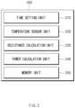
- FIG. 2is a block diagram illustrating a configuration of an apparatus for calculating battery power according to an embodiment of the present invention.
- an apparatus for calculating battery power 200may include a time setting unit 210, a temperature sensor unit 220, a resistance calculation unit 230, a power calculation unit 240, and a memory unit 250.
- the time setting unit 210may set a target time for using the battery cell.
- the target timeis a time during which the battery cell can be used without reaching limit temperature, and may be arbitrarily set by the user.
- the time setting unit 210may set the target time by receiving an input from a user or an external system.
- the time setting unit 210may receive a value calculated in real time according to an operation mode or navigation link information in a vehicle system as the target time.
- the target timemay be set in seconds (sec).
- the temperature sensor unit 220may measure temperature of the battery cell. In this case, the temperature sensor unit 220 may measure the temperature of the battery cell in real time or at a preset time interval.
- the resistance calculation unit 230may calculate the resistance of the battery cell. For example, the resistance calculation unit 230 may calculate resistance based on a voltage and a current applied to the battery cell.
- the resistance calculation unit 230may correct the resistance of the battery cell in consideration of a change in resistance according to the temperature of the battery cell. In this case, the resistance calculation unit 230 may correct the resistance of the battery cell based on a correction coefficient calculated according to a ratio of the resistance at current temperature of the battery cell and the resistance at threshold temperature (or other high temperature condition) of the battery cell. This will be described later with reference to FIG. 5 .
- the resistance calculation unit 230may correct the resistance of the battery cell in consideration of a change in resistance according to a state of charge (SOC) of the battery cell. In this case, the resistance calculation unit 230 may correct the resistance of the battery cell based on a correction coefficient calculated according to a ratio of the resistance at a current SOC of the battery cell and the resistance at the SOC of the battery cell after a preset time.
- SOCstate of charge
- a resistance value according to the temperature of the battery cell and a resistance value according to the SOCmay be values obtained in advance through an experiment or calculation. These values may be stored in the memory unit 250.
- the power calculation unit 240may calculate an optimum current value usable without exceeding the threshold temperature of the battery cell during the target time, based on the temperature and resistance of the battery.
- the present inventionis not limited thereto, and the power calculation unit 240 may calculate an optimum voltage value in a range of optimum power usable without exceeding the threshold temperature of the battery cell during the target time.
- the threshold temperaturemay be a predetermined value or a value calculated in real time according to an operation mode of a system including the battery cell.
- the power calculation unit 240may calculate the optimum current value in consideration of a total amount of heat from the current temperature of the battery cell to the threshold temperature, an amount of heat generation generated during charging and discharging of the battery cell, and an amount of cooling heat. This will be described later with reference to FIGS. 3 and 4 .
- the memory unit 250may store a parameter for calculating the optimum current value of the battery cell.
- parameter valuesmay include mass of the battery cell, heat capacity of the battery cell, thermal resistance, a correction coefficient that reflects the change in resistance according to the temperature and SOC of the battery cell described above, a correction coefficient for calculating an amount of heat generation of the battery cell, etc.
- the memory unit 250may store the temperature, SOC, and resistance value of the battery cell.
- the apparatus for calculating battery poweraccording to the embodiment of the present invention, it is possible to maintain the battery at an appropriate temperature during the target time and efficiently perform energy management of the vehicle by calculating the optimum power value for using the battery without reaching the limit temperature during the target time.
- FIG. 3is a diagram illustrating a thermal model for calculating an optimum power value of a battery.
- FIG. 3it illustrates that a coolant is provided in a plurality of battery cells.
- the total amount of heat (Q_tot) from the current temperature until reaching the threshold temperature of the battery cellis equal to a value obtained by subtracting the amount of cooling heat (Q_cool) from the amount of heat generation of the battery cell (Q_gen) generated during charging and discharging. Based on this, a process of obtaining the optimum power value of the battery cell will be described with reference to FIG. 4 .
- FIG. 4is a diagram schematically illustrating a process of calculating an optimum power value in the apparatus for calculating battery power according to an embodiment of the present invention.
- the userfirst inputs a target time t target for using the battery without reaching the limit temperature.
- temperature T cellnow of the battery cell is measured in real time and a resistance value R cell,norm of the battery cell is calculated.
- the resistance of the battery cellmay be corrected in consideration of the temperature and SOC of the battery cell.
- fixed parameterse.g., heat capacity, mass, various correction coefficients of the battery cell, etc.
- the apparatus for calculating battery powermay calculate optimum power, and may drive the battery by outputting an optimum current value I opt,RMS for operating at optimum power.
- the total amount of heat Q tot when the battery cell reaches the threshold temperature T cell,limit from the current temperature T cell,nowcan be calculated as follows.
- Q totC cell ⁇ m cell ⁇ T cell ,limit ⁇ T cell ,now
- the threshold temperature T cell,limitmay also be a value stored in the memory as a predetermined value, and the current temperature T cell,now may be a measured value by a sensor (e.g., temperature sensor unit 220 of FIG. 2 ) of the battery management system BMS.
- the threshold temperature T cell,limitmay not be a fixed value but may be a value calculated in real time according to the operation mode of the system including the battery cell. In this case, the threshold temperature T cell,limit may be separately calculated by the battery management system BMS.
- the total amount of heat Q tot of the batteryis equal to the value obtained by subtracting the amount of cooling heat Q cool from the amount of heat generation Q gen of the battery cell generated during charging and discharging.
- Q totQ gen ⁇ Q cool
- the amount of heat generation Q gen of the battery cellmay be calculated as follows.
- Q gen⁇ ⁇ I opt ,RMS 2 ⁇ R cell ,norm ⁇ t target
- ⁇may be a value stored in the memory as a correction coefficient
- I opt,RMSis an RMS value A of the optimum current to be calculated
- R cell,normrepresents the resistance of the battery cell.
- the battery cell resistance value R cell,norm required to calculate the amount of heat generation Q genis a value that can represent the battery cell resistance up to the high temperature conditions, and may be used by being corrected as follows to suit the high temperature conditions from a resistance value Rcell,est measured in real time by the battery management system (BMS).
- R cell ,normk ⁇ R cell ,est
- kis a correction coefficient suitable for high temperature conditions (k ⁇ 1), and the battery cell resistance may vary according to the current temperature conditions at which the battery cell resistance is measured.
- the resistance value of the battery cellmay include not only the correction coefficient k according to the temperature condition, but also a correction coefficient k' according to a main used SOC region.
- k'may be around 1 in a charge sustain (CS) mode to be described later, and may be greater than 1 in a charge depletion (CD) mode.
- the correction coefficients k and k' according to the temperature and SOCmay be values stored in the memory.
- Expression (4) described abovemay be expressed as follows.
- R cell ,normk ⁇ k ′ ⁇ R cell ,est
- the cooling heat Q cool of the battery cellmay be calculated as follows.
- Q coolT cell ,limit + T cell ,now 2 ⁇ T coolant R th ⁇ t target
- T cell ,limit + T cellnow 2 was used to use the temperature of the battery cell on average
- T coolantrepresents the temperature of the coolant.
- R threpresents thermal resistance
- t targetis the time (target time) s during which the current may be used without exceeding the threshold temperature T cell,limit .
- R th , T coolant , and T cell,limitmay be stored in the memory as fixed values.
- I opt,RMSC p ,cell T cell ,max ⁇ T cell ,now ⁇ R cell ,norm + T cell ,limit + T cell ,now 2 ⁇ T coolant ⁇ R cell ,norm R th ⁇ t target
- the optimum RMS current I opt,RMS in a range not reaching the threshold temperature during the target time t targetmay be calculated by using the battery cell temperature T cell,now and resistance R cell,norm at the point in time of calculation, including the target time t target , as input values.
- FIG. 5is a diagram illustrating a change in battery resistance according to temperature.
- ais the battery resistance at the current temperature
- bis the battery resistance in a high temperature state (e.g., threshold temperature) after a prescribed time.
- the correction coefficient of resistance according to temperatureis not limited to the expression described above, and may be calculated in various ways.
- FIG. 6is a diagram illustrating a change in SOC according to an operation of a battery and a change in battery resistance according to the SOC.
- the SOC of the battery cellmay be divided into two modes according to an operating state. Specifically, in an initial SOC, the SOC gradually decreases as the battery is more actively used (discharged), and this is referred to as a charge depletion (CD) mode. In addition, when the SOC reaches a prescribed level (for example, 30%), it maintains the SOC by equalizing the use amount (discharging amount) and charging amount of the battery through regenerative braking, which is called a charge sustain (CS) mode.
- a prescribed levelfor example, 30%
- (b) of FIG. 6illustrates a change in battery resistance according to the SOC in the CD mode (during discharging) described above.
- the resistance of the batterytends to decrease as the SOC increases. That is, the SOC of a battery generally decreases as the use time increases, and conversely, the resistance of the battery may gradually increase.
- ais the battery resistance at the current SOC
- bis the battery resistance in a state where the SOC is decreased after a prescribed time.
- k'1
- the correction coefficient of resistance according to the SOCis not limited to the expression described above, and may be calculated in various ways.
- FIG. 7is a diagram illustrating a change in battery current by the apparatus for calculating battery power according to the embodiment of the present invention.
- the battery currentis applied within the range of the calculated limit value of the RMS current. That is, in the apparatus for calculating battery power according to an embodiment of the present invention, compared to the case of managing power by using the measured value of the dynamically changing current used in the vehicle as an input value, the output may be statically managed in the vehicle by providing an appropriate RMS current value for the arrival time t of the threshold temperature to a control unit (e.g., electronic control unit (ECU)) of the vehicle.
- ECUelectronice control unit
- FIG. 8is a flowchart illustrating a method for calculating battery power according to an embodiment of the present invention.
- a target time for using a battery cellmay be set (S810).
- the target timeis a time during which the user uses the battery without reaching threshold temperature of the battery cell, and may be set by the user.
- a value calculated in real time according to an operation mode or navigation link information in a vehicle systemmay be received.
- the threshold temperaturemay be a value determined in advance and stored in a memory, or may be a value calculated in real time according to an operation mode of a system including the battery cell.
- the temperature of the battery cellmay be measured (S820), and the resistance of the battery cell may be calculated (S830).
- the resistance of the battery cellmay be calculated first and then the temperature of the battery cell may be measured.
- an optimum current value usable without exceeding the threshold temperature of the battery cell during the target timemay be calculated (S840).
- the optimum current valuemay be calculated in consideration of the total amount of heat from the current temperature of the battery cell until reaching the threshold temperature, the amount of heat generation generated during charging and discharging of the battery cell, and the amount of cooling heat.
- various parameterse.g., heat capacity of the battery, thermal resistance, various correction coefficients, etc.
- required to calculate the optimum current valuemay be stored in a separate memory.
- the method for calculating battery power according to the embodiment of the present inventionmay further include correcting the resistance of the battery cell in consideration of a change in resistance according to the temperature of the battery cell.
- the resistance of the battery cellmay be corrected based on a correction coefficient calculated according to a ratio of the resistance at the current temperature of the battery cell and the resistance at the threshold temperature of the battery cell.
- the method for calculating battery power according to the embodiment of the present inventionmay further include correcting the resistance of the battery cell in consideration of a change in resistance according to the SOC of the battery cell.
- the resistance of the battery cellmay be corrected based on a correction coefficient calculated according to a ratio of the resistance at the current SOC of the battery cell and the resistance at the SOC after a preset time of the battery cell.
- the method for calculating battery powerit is possible to maintain the battery at an appropriate temperature during the target time and efficiently perform energy management of the vehicle by calculating the optimum power value for using the battery without reaching the limit temperature during the target time.
- FIG. 9is a diagram illustrating a hardware configuration of the apparatus for calculating battery power according to the embodiment of the present invention.
- a battery management system 900may include a microcontroller unit (MCU) 910 that controls various processing and each configuration, a memory 920 in which an operating system program and various programs (e.g., a battery pack abnormality diagnosis program or a battery pack temperature estimation program) are recorded, an input/output interface 930 that provides input interface and output interface between a battery cell module and/or a semiconductor switching device, and a communication interface 940 capable of communicating with the outside through a wired or wireless communication network.
- a computer program according to the present inventionmay be recorded in the memory 920 and processed by the microcontroller 910, thereby capable of being implemented as, for example, a module that performs each functional block illustrated in FIGS. 2 and 4 .
Landscapes
- Physics & Mathematics (AREA)
- General Physics & Mathematics (AREA)
- Engineering & Computer Science (AREA)
- Manufacturing & Machinery (AREA)
- Chemical & Material Sciences (AREA)
- Chemical Kinetics & Catalysis (AREA)
- Electrochemistry (AREA)
- General Chemical & Material Sciences (AREA)
- Automation & Control Theory (AREA)
- Microelectronics & Electronic Packaging (AREA)
- Secondary Cells (AREA)
- Charge And Discharge Circuits For Batteries Or The Like (AREA)
Description
- This application claims the benefit of
Korean Patent Application No. 10-2019-0121707, filed on October 1, 2019 - The present invention relates to an apparatus and method for calculating battery power usable without reaching limit temperature during a target time in consideration of heating and cooling conditions of a battery.
- Recently, research and development on a secondary battery are being actively conducted. Here, the secondary battery is a battery capable of charging and discharging, and is meant to include all of a conventional Ni/Cd battery, Ni/MH battery, etc. and a recent lithium ion battery. Among the secondary batteries, the lithium ion battery has an advantage of having much higher energy density compared to the conventional Ni/Cd battery, Ni/MH battery, etc. In addition, the lithium ion battery can be manufactured in a small size and light weight, and thus the lithium ion battery is used as a power source for a mobile device. In addition, the lithium ion battery is attracting attention as a next-generation energy storage medium as its range of use has been expanded to a power source for an electric vehicle.
- In addition, the secondary battery is generally used as a battery pack including a battery module in which a plurality of battery cells are connected in series and/or in parallel. In addition, a state and operation of the battery pack are managed and controlled by a battery management system.
- In such a battery management system, use power of a battery is generally calculated with conditions such as a current state of charge (SOC) or temperature as the reference. In this case, when the battery reaches the limit temperature while using the maximum power, power is collectively limited to a prescribed value. However, when power is used to the maximum until the limit temperature of the battery is reached, and then power is rapidly limited, there is a problem in that a vehicle cannot efficiently manage energy.
US 2010/079111 A1 relates to a charge discharge control apparatus for controlling charging and discharging of a battery for use in a vehicle.US 2011/257914 A1 relates to device and method of estimating charged state of a secondary battery and to device and method of estimating charged state of a secondary battery that successively calculate SOC indicating remaining capacity of the secondary battery.US 2019/173136 A1 relates to a vehicular battery cooling system and a method of controlling the same, and to a vehicular battery cooling system and a method of controlling the same for intelligently controlling a current usage using a heat absorption member of a battery terminal and driving on an actual road.US 2015/104680 A1 relates to determining condition of a degraded battery temperature sensor.JP 2015 220956 A - An object of the present invention is to provide an apparatus and method for calculating battery power capable of maintaining a battery at an appropriate temperature during the target time and efficiently performing energy management of a vehicle by calculating an optimum power value usable for the battery without reaching the limit temperature during the target time.
- The invention provides an apparatus for calculating a current value of a battery cell according to
claim 1, and a method for calculating a current value of a battery cell according toclaim 10. Preferred embodiments are provided in the dependent claims. - According to the apparatus and method of the present invention, it is possible to maintain the battery at an appropriate temperature during the target time and efficiently perform energy management of the vehicle by calculating an optimum power value usable for the battery without reaching the limit temperature during the target time.
FIG. 1 is a block diagram illustrating a configuration of a battery control system;FIG. 2 is a block diagram illustrating a configuration of an apparatus for calculating battery power according to an embodiment of the present invention;FIG. 3 is a diagram illustrating a thermal model for calculating an optimum power value of a battery;FIG. 4 is a diagram schematically illustrating a process of calculating the optimum power value in the apparatus for calculating battery power according to an embodiment of the present invention;FIG. 5 is a diagram illustrating a change in battery resistance according to temperature;FIG. 6 is a diagram illustrating a change in SOC according to an operation of a battery and a change in battery resistance according to the SOC;FIG. 7 is a diagram illustrating a change in battery current by the apparatus for calculating battery power according to the embodiment of the present invention;FIG. 8 is a flowchart illustrating a method for calculating battery power according to an embodiment of the present invention; andFIG. 9 is a diagram illustrating a hardware configuration of the apparatus for calculating battery power according to the embodiment of the present invention.- Hereinafter, various embodiments of the present invention will be described in detail with reference to the accompanying drawings. In this document, the same reference numerals are used for the same constituent elements in the drawings, and duplicate descriptions for the same constituent elements are omitted.
- With respect to the various embodiments of the present invention disclosed in this document, specific structural or functional descriptions have been exemplified for the purpose of describing the embodiments of the present invention only, and various embodiments of the present invention may be embodied in various forms and should not be construed as being limited to the embodiments described in this document.
- Expressions such as "first", "second", "firstly", or "secondly", etc. used in various embodiments may modify various constituent elements regardless of order and/or importance, and do not limit corresponding constituent elements. For example, without deviating from the scope of the present invention, a first constituent element may be named as a second constituent element, and similarly, the second constituent element may also be renamed as the first constituent element.
- The terms used in this document are only used to describe a specific embodiment, and may not be intended to limit the scope of other embodiments. Singular expressions may include plural expressions unless the context clearly indicates otherwise.
- All terms used herein, including technical or scientific terms, may have the same meaning as generally understood by a person of ordinary skill in the art. Terms defined in a generally used dictionary may be interpreted as having the same or similar meaning as the meaning in the context of the related technology, and are not to be interpreted as an ideal or excessively formal meaning unless explicitly defined in this document. In some cases, even terms defined in this document cannot be interpreted to exclude embodiments of the present invention.
FIG. 1 is a block diagram illustrating a configuration of a battery control system.- Referring to
FIG. 1 , a battery management system (BMS) including abattery pack 1 and an upper-level controller 2 included in an upper-level system according to an embodiment of the present invention is schematically illustrated. - As illustrated in
FIG. 1 , thebattery pack 1 includes abattery module 10 composed of one or more battery cells and capable of charging and discharging, aswitching unit 14 connected in series to a positive terminal side or a negative terminal side of thebattery module 10 to control a charge and discharge current flow of thebattery module 10, and abattery management system 20 that monitors a voltage, current, temperature, etc. of thebattery pack 1 to control and manage thebattery module 10 to prevent over-charging, over-discharging, etc. - Here, the
switching unit 14 is a semiconductor switching element for controlling a current flow for charging or discharging of thebattery module 10, and, for example, at least one MOSFET may be used - In addition, the
BMS 20 may measure or calculate a voltage and current of a gate, source, and drain of the semiconductor switching element in order to monitor the voltage, current, temperature, etc. of thebattery pack 1, and may measure the current, voltage, temperature, etc. of the battery pack using asensor 12 provided adjacent to thesemiconductor switching element 14. TheBMS 20 is an interface that receives values obtained by measuring various parameters described above, and may include a plurality of terminals and a circuit connected to these terminals to perform processing for input values. - In addition, the
BMS 20 may control ON/OFF of theswitching element 14, for example, a MOSFET, and may be connected to thebattery module 10 to monitor a state of thebattery module 10. - The
upper controller 2 may transmit a control signal for the battery module to theBMS 20. Accordingly, an operation of theBMS 20 may be controlled based on a signal applied from the host controller. The battery cell of the present invention may be configured to be included in a battery pack used in an energy storage system (ESS) or a vehicle, etc. However, the battery cell of the present invention is not limited to these uses. - Since the configuration of the
battery pack 1 and the configuration of theBMS 20 are known configurations, a more detailed description thereof will be omitted. FIG. 2 is a block diagram illustrating a configuration of an apparatus for calculating battery power according to an embodiment of the present invention.- Referring to
FIG. 2 , an apparatus for calculatingbattery power 200 according to an embodiment of the present invention may include atime setting unit 210, atemperature sensor unit 220, aresistance calculation unit 230, apower calculation unit 240, and amemory unit 250. - The
time setting unit 210 may set a target time for using the battery cell. Here, the target time is a time during which the battery cell can be used without reaching limit temperature, and may be arbitrarily set by the user. In this case, thetime setting unit 210 may set the target time by receiving an input from a user or an external system. - In addition, the
time setting unit 210 may receive a value calculated in real time according to an operation mode or navigation link information in a vehicle system as the target time. For example, the target time may be set in seconds (sec). - The
temperature sensor unit 220 may measure temperature of the battery cell. In this case, thetemperature sensor unit 220 may measure the temperature of the battery cell in real time or at a preset time interval. - The
resistance calculation unit 230 may calculate the resistance of the battery cell. For example, theresistance calculation unit 230 may calculate resistance based on a voltage and a current applied to the battery cell. - In addition, the
resistance calculation unit 230 may correct the resistance of the battery cell in consideration of a change in resistance according to the temperature of the battery cell. In this case, theresistance calculation unit 230 may correct the resistance of the battery cell based on a correction coefficient calculated according to a ratio of the resistance at current temperature of the battery cell and the resistance at threshold temperature (or other high temperature condition) of the battery cell. This will be described later with reference toFIG. 5 . - The
resistance calculation unit 230 may correct the resistance of the battery cell in consideration of a change in resistance according to a state of charge (SOC) of the battery cell. In this case, theresistance calculation unit 230 may correct the resistance of the battery cell based on a correction coefficient calculated according to a ratio of the resistance at a current SOC of the battery cell and the resistance at the SOC of the battery cell after a preset time. - For example, a resistance value according to the temperature of the battery cell and a resistance value according to the SOC may be values obtained in advance through an experiment or calculation. These values may be stored in the
memory unit 250. - The
power calculation unit 240 may calculate an optimum current value usable without exceeding the threshold temperature of the battery cell during the target time, based on the temperature and resistance of the battery. However, the present invention is not limited thereto, and thepower calculation unit 240 may calculate an optimum voltage value in a range of optimum power usable without exceeding the threshold temperature of the battery cell during the target time. Here, the threshold temperature may be a predetermined value or a value calculated in real time according to an operation mode of a system including the battery cell. - The
power calculation unit 240 may calculate the optimum current value in consideration of a total amount of heat from the current temperature of the battery cell to the threshold temperature, an amount of heat generation generated during charging and discharging of the battery cell, and an amount of cooling heat. This will be described later with reference toFIGS. 3 and4 . - The
memory unit 250 may store a parameter for calculating the optimum current value of the battery cell. For example, parameter values may include mass of the battery cell, heat capacity of the battery cell, thermal resistance, a correction coefficient that reflects the change in resistance according to the temperature and SOC of the battery cell described above, a correction coefficient for calculating an amount of heat generation of the battery cell, etc. Also, thememory unit 250 may store the temperature, SOC, and resistance value of the battery cell. - As described above, according to the apparatus for calculating battery power according to the embodiment of the present invention, it is possible to maintain the battery at an appropriate temperature during the target time and efficiently perform energy management of the vehicle by calculating the optimum power value for using the battery without reaching the limit temperature during the target time.
FIG. 3 is a diagram illustrating a thermal model for calculating an optimum power value of a battery.- Referring to
FIG. 3 , it illustrates that a coolant is provided in a plurality of battery cells. In this case, the total amount of heat (Q_tot) from the current temperature until reaching the threshold temperature of the battery cell is equal to a value obtained by subtracting the amount of cooling heat (Q_cool) from the amount of heat generation of the battery cell (Q_gen) generated during charging and discharging. Based on this, a process of obtaining the optimum power value of the battery cell will be described with reference toFIG. 4 . FIG. 4 is a diagram schematically illustrating a process of calculating an optimum power value in the apparatus for calculating battery power according to an embodiment of the present invention.- Referring to
FIG. 4 , in order to calculate the optimum power of the battery in the apparatus for calculating battery power according to the embodiment of the present invention, the user first inputs a target time ttarget for using the battery without reaching the limit temperature. - In addition, temperature Tcell,now of the battery cell is measured in real time and a resistance value Rcell,norm of the battery cell is calculated. In this case, as described above, the resistance of the battery cell may be corrected in consideration of the temperature and SOC of the battery cell. Then, in order to calculate the optimum power of the battery, fixed parameters (e.g., heat capacity, mass, various correction coefficients of the battery cell, etc.) stored in the memory are introduced into a calculation expression.
- Through this process, the apparatus for calculating battery power according to the embodiment of the present invention may calculate optimum power, and may drive the battery by outputting an optimum current value Iopt,RMS for operating at optimum power.
- Specifically, a process of deriving an expression for calculating the optimum current value is as follows.
- The total amount of heat Qtot when the battery cell reaches the threshold temperature Tcell,limit from the current temperature Tcell,now can be calculated as follows.

- Ccell represents the heat capacity of the battery cell, and mcell represents the mass of the battery cell, which may be values stored in the memory. In addition, the threshold temperature Tcell,limit may also be a value stored in the memory as a predetermined value, and the current temperature Tcell,now may be a measured value by a sensor (e.g.,
temperature sensor unit 220 ofFIG. 2 ) of the battery management system BMS. However, as described above, the threshold temperature Tcell,limit may not be a fixed value but may be a value calculated in real time according to the operation mode of the system including the battery cell. In this case, the threshold temperature Tcell,limit may be separately calculated by the battery management system BMS. - Meanwhile, the total amount of heat Qtot of the battery is equal to the value obtained by subtracting the amount of cooling heat Qcool from the amount of heat generation Qgen of the battery cell generated during charging and discharging.

- In addition, the amount of heat generation Qgen of the battery cell may be calculated as follows.

- α may be a value stored in the memory as a correction coefficient, Iopt,RMS is an RMS value A of the optimum current to be calculated, and Rcell,norm represents the resistance of the battery cell.
- The battery cell resistance value Rcell,norm required to calculate the amount of heat generation Qgen is a value that can represent the battery cell resistance up to the high temperature conditions, and may be used by being corrected as follows to suit the high temperature conditions from a resistance valueRcell,est measured in real time by the battery management system (BMS).

- Here, k is a correction coefficient suitable for high temperature conditions (k < 1), and the battery cell resistance may vary according to the current temperature conditions at which the battery cell resistance is measured.
- In addition, as described above, the resistance value of the battery cell may include not only the correction coefficient k according to the temperature condition, but also a correction coefficient k' according to a main used SOC region. Here, k' may be around 1 in a charge sustain (CS) mode to be described later, and may be greater than 1 in a charge depletion (CD) mode. In this case, the correction coefficients k and k' according to the temperature and SOC may be values stored in the memory. As such, when applying the correction coefficient according to the SOC, Expression (4) described above may be expressed as follows.

- Meanwhile, the cooling heat Qcool of the battery cell may be calculated as follows.

- In this case,

- If Expression (1), Expression (3), and Expression (5) are respectively substituted in Expression (2) described above, it is as follows.

- If Expression (6) described above is summarized for Iopt,RMS, it is as follows, which is the final expression implemented in the apparatus for calculating battery power (or BMS) according to the embodiment of the present invention.

- Since the values stored in the memory described above are predetermined values, Iopt,RMS may be regarded as a function by the following factors.

- As such, the optimum RMS current Iopt,RMS in a range not reaching the threshold temperature during the target time ttarget may be calculated by using the battery cell temperature Tcell,now and resistance Rcell,norm at the point in time of calculation, including the target time ttarget, as input values.
FIG. 5 is a diagram illustrating a change in battery resistance according to temperature.- Referring to
FIG. 5 , it can be seen that the resistance of the battery tends to decrease as the temperature increases. That is, since the battery generally increases in temperature as use time increases, the resistance of the battery may gradually decrease. Accordingly, in the apparatus for calculating battery power according to the embodiment of the present invention, the correction coefficient may be calculated as follows by reflecting such a resistance characteristic of the battery.
- Here, a is the battery resistance at the current temperature, and b is the battery resistance in a high temperature state (e.g., threshold temperature) after a prescribed time. However, the correction coefficient of resistance according to temperature is not limited to the expression described above, and may be calculated in various ways.
FIG. 6 is a diagram illustrating a change in SOC according to an operation of a battery and a change in battery resistance according to the SOC.- Referring to (a) of
FIG. 6 , the SOC of the battery cell may be divided into two modes according to an operating state. Specifically, in an initial SOC, the SOC gradually decreases as the battery is more actively used (discharged), and this is referred to as a charge depletion (CD) mode. In addition, when the SOC reaches a prescribed level (for example, 30%), it maintains the SOC by equalizing the use amount (discharging amount) and charging amount of the battery through regenerative braking, which is called a charge sustain (CS) mode. - Meanwhile, (b) of
FIG. 6 illustrates a change in battery resistance according to the SOC in the CD mode (during discharging) described above. As can be seen from the graph, the resistance of the battery tends to decrease as the SOC increases. That is, the SOC of a battery generally decreases as the use time increases, and conversely, the resistance of the battery may gradually increase. Accordingly, in the apparatus for calculating battery power according to the embodiment of the present invention, the correction coefficient may be calculated as follows by reflecting such a resistance characteristic of the battery.
- Here, a is the battery resistance at the current SOC, and b is the battery resistance in a state where the SOC is decreased after a prescribed time. Meanwhile, in the CS mode, since the SOC is kept constant, there is no difference between the resistance value at the point in time of measurement and after the measurement, and thus k' = 1. However, the correction coefficient of resistance according to the SOC is not limited to the expression described above, and may be calculated in various ways.
FIG. 7 is a diagram illustrating a change in battery current by the apparatus for calculating battery power according to the embodiment of the present invention.- Referring to
FIG. 7 , it can be seen that, according to the apparatus for calculating battery power according to an embodiment of the present invention, the battery current is applied within the range of the calculated limit value of the RMS current. That is, in the apparatus for calculating battery power according to an embodiment of the present invention, compared to the case of managing power by using the measured value of the dynamically changing current used in the vehicle as an input value, the output may be statically managed in the vehicle by providing an appropriate RMS current value for the arrival time t of the threshold temperature to a control unit (e.g., electronic control unit (ECU)) of the vehicle. - As such, that is, according to the apparatus for calculating battery power according to the embodiment of the present invention, since the output can be managed at its optimum within the range where the current value of the RMS maintains the reference value, a margin for using a large current may be secured as much as the amount of using less current in the initial time.
FIG. 8 is a flowchart illustrating a method for calculating battery power according to an embodiment of the present invention.- Referring to
FIG. 8 , first, a target time for using a battery cell may be set (S810). The target time is a time during which the user uses the battery without reaching threshold temperature of the battery cell, and may be set by the user. In this case, as the target time, a value calculated in real time according to an operation mode or navigation link information in a vehicle system may be received. - In addition, the threshold temperature may be a value determined in advance and stored in a memory, or may be a value calculated in real time according to an operation mode of a system including the battery cell.
- Then, the temperature of the battery cell may be measured (S820), and the resistance of the battery cell may be calculated (S830). However, contrary to that illustrated in
FIG. 8 , the resistance of the battery cell may be calculated first and then the temperature of the battery cell may be measured. - Next, based on the temperature and resistance of the battery, an optimum current value usable without exceeding the threshold temperature of the battery cell during the target time may be calculated (S840). In this case, the optimum current value may be calculated in consideration of the total amount of heat from the current temperature of the battery cell until reaching the threshold temperature, the amount of heat generation generated during charging and discharging of the battery cell, and the amount of cooling heat. In addition, various parameters (e.g., heat capacity of the battery, thermal resistance, various correction coefficients, etc.) required to calculate the optimum current value may be stored in a separate memory.
- Meanwhile, although not illustrated in
FIG. 8 , the method for calculating battery power according to the embodiment of the present invention may further include correcting the resistance of the battery cell in consideration of a change in resistance according to the temperature of the battery cell. In this case, as described above, the resistance of the battery cell may be corrected based on a correction coefficient calculated according to a ratio of the resistance at the current temperature of the battery cell and the resistance at the threshold temperature of the battery cell. - In addition, the method for calculating battery power according to the embodiment of the present invention may further include correcting the resistance of the battery cell in consideration of a change in resistance according to the SOC of the battery cell. In this case, the resistance of the battery cell may be corrected based on a correction coefficient calculated according to a ratio of the resistance at the current SOC of the battery cell and the resistance at the SOC after a preset time of the battery cell.
- As such, according to the method for calculating battery power according to the embodiment of the present invention, it is possible to maintain the battery at an appropriate temperature during the target time and efficiently perform energy management of the vehicle by calculating the optimum power value for using the battery without reaching the limit temperature during the target time.
FIG. 9 is a diagram illustrating a hardware configuration of the apparatus for calculating battery power according to the embodiment of the present invention.- Referring to
FIG. 9 , abattery management system 900 may include a microcontroller unit (MCU) 910 that controls various processing and each configuration, amemory 920 in which an operating system program and various programs (e.g., a battery pack abnormality diagnosis program or a battery pack temperature estimation program) are recorded, an input/output interface 930 that provides input interface and output interface between a battery cell module and/or a semiconductor switching device, and acommunication interface 940 capable of communicating with the outside through a wired or wireless communication network. As described above, a computer program according to the present invention may be recorded in thememory 920 and processed by themicrocontroller 910, thereby capable of being implemented as, for example, a module that performs each functional block illustrated inFIGS. 2 and4 . - In the above description, just because all constituent elements constituting an embodiment of the present invention are described as being combined into one or operating in combination, the present invention is not necessarily limited to these embodiments, but to the scope of the appended claims.
- In addition, the terms such as "include", "configure" or "have" described above mean that the corresponding constituent element may be embedded unless otherwise described, and thus the terms should be interpreted as being capable of further including other constituent elements, rather than excluding other constituent elements. All terms used herein including technical or scientific terms may have the same meaning as generally understood by a person of ordinary skill in the art, unless otherwise defined. Terms generally used, such as terms defined in the dictionary, should be interpreted as being consistent with the meaning of the context of related technology, and are not to be interpreted as an ideal or excessively formal meaning unless explicitly defined in the present invention.
- The above description is merely illustrative of the technical idea of the present invention, and those of ordinary skill in the art to which the present invention pertains will be able to make various modifications and variations without deviating from the essential characteristics of the present invention. Accordingly, the embodiments disclosed in the present invention are not intended to limit the technical idea of the present invention, but to explain the technical idea, and the scope of the technical idea of the present invention is not limited by these embodiments. The scope of protection of the present invention should be interpreted by the claims set forth below.


Claims (12)
- An apparatus for calculating a current value of a battery cell (200) comprising:a timer (210) configured to set a target time for using the battery cell;a temperature sensor (220) configured to measure a temperature of the battery cell; anda controller (230, 240) configured to:calculate a resistance of the battery cell; andcalculate the current value usable without exceeding a threshold temperature of the battery cell during the target time, based on the measured temperature and the calculated resistance of the battery cell.
- The apparatus of claim 1, further comprising:
memory (250) configured to store a parameter for calculating the current value of the battery cell. - The apparatus of claim 1,
wherein the controller is configured to correct the calculated resistance of the battery cell based at least in part on a change in resistance according to the temperature of the battery cell. - The apparatus of claim 3,
wherein the controller is configured to correct the calculated resistance of the battery cell based on a correction coefficient calculated according to a ratio between resistance at a current temperature of the battery cell and resistance at the threshold temperature of the battery cell. - The apparatus of claim 1,
wherein the controller is configured to correct the resistance of the battery cell in consideration of a change in resistance according to a state of charge (SOC) of the battery cell. - The apparatus of claim 5,
wherein the controller is configured to correct the resistance of the battery cell based on a correction coefficient calculated according to a ratio between resistance at a current SOC of the battery cell and resistance at an SOC of the battery cell after a preset time. - The apparatus of claim 1,
wherein the threshold temperature is a predetermined value or a value calculated in real time according to an operation mode of a system including the battery cell. - The apparatus of claim 1,
wherein the controller is configured to calculate the current value based at least in part on a total amount of heat generated from a time that the battery cell is at a current temperature until a time that the battery cell reaches the threshold temperature. - The apparatus of claim 1,
wherein the timer (210) is configured to set the target time in response to an input from a user or an external system. - A method for calculating a current value of a battery cell comprising:setting (S810) a target time for using the battery cell;measuring (S820) a temperature of the battery cell;calculating (S830) a resistance of the battery cell; andcalculating (S840) the current value usable without exceeding a threshold temperature of the battery cell during the target time, based on the measured temperature and the calculated resistance of the battery cell.
- The method of claim 10, further comprising:
correcting the calculated resistance of the battery cell based at least in part on a change in resistance according to the temperature of the battery cell. - The method of claim 10, further comprising:
correcting the calculated resistance of the battery cell based at least in part on a change in resistance according to an SOC of the battery cell.
Applications Claiming Priority (2)
| Application Number | Priority Date | Filing Date | Title |
|---|---|---|---|
| KR1020190121707AKR102742036B1 (en) | 2019-10-01 | 2019-10-01 | Appratus and method for calculating battery power |
| PCT/KR2020/013023WO2021066396A1 (en) | 2019-10-01 | 2020-09-25 | Apparatus and method for calculating battery power |
Publications (3)
| Publication Number | Publication Date |
|---|---|
| EP3992650A1 EP3992650A1 (en) | 2022-05-04 |
| EP3992650A4 EP3992650A4 (en) | 2022-08-24 |
| EP3992650B1true EP3992650B1 (en) | 2024-07-31 |
Family
ID=75338251
Family Applications (1)
| Application Number | Title | Priority Date | Filing Date |
|---|---|---|---|
| EP20871542.5AActiveEP3992650B1 (en) | 2019-10-01 | 2020-09-25 | Apparatus and method for calculating battery power |
Country Status (8)
| Country | Link |
|---|---|
| US (1) | US11828806B2 (en) |
| EP (1) | EP3992650B1 (en) |
| JP (1) | JP7359350B2 (en) |
| KR (1) | KR102742036B1 (en) |
| CN (1) | CN114127571B (en) |
| ES (1) | ES2990053T3 (en) |
| HU (1) | HUE067840T2 (en) |
| WO (1) | WO2021066396A1 (en) |
Families Citing this family (6)
| Publication number | Priority date | Publication date | Assignee | Title |
|---|---|---|---|---|
| KR20220057368A (en)* | 2020-10-29 | 2022-05-09 | 주식회사 엘지에너지솔루션 | Apparatus and method for managing battery, battery managing system |
| CN115064808A (en)* | 2022-05-20 | 2022-09-16 | 远景智能国际私人投资有限公司 | Current control method, device, device and storage medium |
| KR20240174631A (en)* | 2023-06-09 | 2024-12-17 | 주식회사 엘지에너지솔루션 | Battery charging control device and method |
| KR20240176516A (en)* | 2023-06-16 | 2024-12-24 | 주식회사 엘지에너지솔루션 | Apparatus and method for inspecting defect of battery cell and system using the same |
| KR20250094025A (en)* | 2023-12-18 | 2025-06-25 | 주식회사 엘지에너지솔루션 | Apparatus for battery management and method for battery control |
| CN118962230A (en)* | 2024-10-09 | 2024-11-15 | 浙江欣旺达电子有限公司 | Method, system and electronic device for updating battery output power limit |
Family Cites Families (34)
| Publication number | Priority date | Publication date | Assignee | Title |
|---|---|---|---|---|
| JPH06188641A (en)* | 1992-12-17 | 1994-07-08 | Fuji Electric Co Ltd | Current detector and current limiter |
| TWI299589B (en)* | 2004-12-27 | 2008-08-01 | Ind Tech Res Inst | A method and an apparatus for a secondary battery protection |
| JP2006304572A (en) | 2005-04-25 | 2006-11-02 | Matsushita Electric Works Ltd | Charging device |
| JP5089883B2 (en) | 2005-12-16 | 2012-12-05 | 日立ビークルエナジー株式会社 | Battery management device |
| JP4984527B2 (en) | 2005-12-27 | 2012-07-25 | トヨタ自動車株式会社 | Secondary battery charge state estimation device and charge state estimation method |
| JP2009207312A (en) | 2008-02-28 | 2009-09-10 | Sanyo Electric Co Ltd | Vehicular power supply unit and current controlling method therefor |
| JP5028315B2 (en) | 2008-03-31 | 2012-09-19 | 川崎重工業株式会社 | Method and apparatus for estimating state of charge of secondary battery |
| JP4930482B2 (en)* | 2008-09-30 | 2012-05-16 | 株式会社デンソー | Battery charge / discharge control device |
| JP5331493B2 (en)* | 2009-01-13 | 2013-10-30 | 日立ビークルエナジー株式会社 | Battery control device |
| JP5378023B2 (en) | 2009-03-24 | 2013-12-25 | 三洋電機株式会社 | Power supply device for vehicle and cooling method thereof |
| JP5126150B2 (en) | 2009-04-09 | 2013-01-23 | トヨタ自動車株式会社 | Storage capacity estimation device and storage capacity estimation method |
| JP2011257219A (en) | 2010-06-08 | 2011-12-22 | Nissan Motor Co Ltd | Internal resistance of secondary battery and calculation device for calculating open voltage |
| KR20120024009A (en)* | 2010-09-03 | 2012-03-14 | 현대모비스 주식회사 | Battery sensor module |
| US9252624B2 (en) | 2011-06-10 | 2016-02-02 | Hitachi Automotive Systems, Ltd. | Battery control device and battery system |
| US10078116B2 (en) | 2012-02-29 | 2018-09-18 | Nec Energy Devices, Ltd. | Battery pack and method for calculating electric energy of battery pack |
| JP6119402B2 (en)* | 2012-05-29 | 2017-04-26 | 株式会社Gsユアサ | Internal resistance estimation device and internal resistance estimation method |
| KR102037149B1 (en)* | 2013-09-23 | 2019-10-28 | 현대모비스 주식회사 | Current Measurement Apparatus and The Method of Using Temperature Dependent Resistance |
| US10086718B2 (en)* | 2013-10-15 | 2018-10-02 | Ford Global Technologies, Llc | System and method for operating a battery pack |
| KR101854218B1 (en) | 2013-10-22 | 2018-05-03 | 삼성에스디아이 주식회사 | Battery pack, energy storage system, and method of charging the battery pack |
| JP2015191777A (en)* | 2014-03-28 | 2015-11-02 | 三菱電機株式会社 | Storage system and battery pack operation method |
| JP2015220956A (en)* | 2014-05-21 | 2015-12-07 | 三菱自動車工業株式会社 | Charger |
| CN105467324B (en)* | 2014-09-30 | 2020-03-03 | 株式会社杰士汤浅国际 | Battery degradation determination device, battery degradation determination method, and battery pack |
| KR101685130B1 (en)* | 2014-12-19 | 2016-12-09 | 주식회사 엘지화학 | Apparatus and Method for controlling power for secondary battery |
| KR101925002B1 (en) | 2015-08-21 | 2018-12-04 | 주식회사 엘지화학 | Apparatus of Adjusting Charging Condition of Secondary Battery and Method thereof |
| JP6657879B2 (en) | 2015-12-04 | 2020-03-04 | いすゞ自動車株式会社 | Battery control system, hybrid vehicle, and battery control method |
| JP6411318B2 (en)* | 2015-12-09 | 2018-10-24 | 本田技研工業株式会社 | Charging current setting method, charging method, charging device and actuator |
| JP2017117756A (en) | 2015-12-25 | 2017-06-29 | カルソニックカンセイ株式会社 | Control method and control device |
| US11437829B2 (en) | 2016-03-07 | 2022-09-06 | The Regents Of The University Of Michigan | Method to charge lithium-ion batteries with user, cell and temperature awareness |
| WO2017154112A1 (en)* | 2016-03-08 | 2017-09-14 | 株式会社東芝 | Battery monitoring device and method |
| WO2017199629A1 (en)* | 2016-05-18 | 2017-11-23 | 日立オートモティブシステムズ株式会社 | Battery control device |
| US10923774B2 (en)* | 2017-03-07 | 2021-02-16 | Denso Corporation | Battery state estimating device and power supply device |
| KR101998069B1 (en)* | 2017-06-23 | 2019-07-09 | 이정환 | Method and apparatus for fast charging and maximum discharging with less-degradation of battery for an electric car |
| JP6881154B2 (en)* | 2017-08-23 | 2021-06-02 | トヨタ自動車株式会社 | Deterioration state estimation method for secondary batteries and secondary battery system |
| KR102507229B1 (en)* | 2017-12-05 | 2023-03-08 | 현대자동차주식회사 | Battery cooling system and controlling method for vehicle |
- 2019
- 2019-10-01KRKR1020190121707Apatent/KR102742036B1/enactiveActive
- 2020
- 2020-09-25HUHUE20871542Apatent/HUE067840T2/enunknown
- 2020-09-25ESES20871542Tpatent/ES2990053T3/enactiveActive
- 2020-09-25CNCN202080050999.4Apatent/CN114127571B/enactiveActive
- 2020-09-25JPJP2022500158Apatent/JP7359350B2/enactiveActive
- 2020-09-25USUS17/631,920patent/US11828806B2/enactiveActive
- 2020-09-25EPEP20871542.5Apatent/EP3992650B1/enactiveActive
- 2020-09-25WOPCT/KR2020/013023patent/WO2021066396A1/ennot_activeCeased
Also Published As
| Publication number | Publication date |
|---|---|
| WO2021066396A1 (en) | 2021-04-08 |
| JP2022540401A (en) | 2022-09-15 |
| ES2990053T3 (en) | 2024-11-28 |
| CN114127571B (en) | 2024-08-13 |
| US11828806B2 (en) | 2023-11-28 |
| US20220283232A1 (en) | 2022-09-08 |
| KR102742036B1 (en) | 2024-12-13 |
| EP3992650A4 (en) | 2022-08-24 |
| JP7359350B2 (en) | 2023-10-11 |
| HUE067840T2 (en) | 2024-11-28 |
| CN114127571A (en) | 2022-03-01 |
| EP3992650A1 (en) | 2022-05-04 |
| KR20210039186A (en) | 2021-04-09 |
Similar Documents
| Publication | Publication Date | Title |
|---|---|---|
| EP3992650B1 (en) | Apparatus and method for calculating battery power | |
| EP3890097B1 (en) | Charging method and device | |
| KR102634816B1 (en) | An battery monitoring apparatus detecting charge balance of a battery and a method thereof | |
| US9153991B2 (en) | System and method for fast charging of lithium-ion batteries with improved safety | |
| US10873201B2 (en) | Battery management apparatus and method for protecting a lithium iron phosphate cell from over-voltage using the same | |
| EP3410558A1 (en) | Battery control device | |
| US10014706B2 (en) | Model-based fast-charging method based on lithium surface concentration | |
| US10018683B2 (en) | Apparatus and method for estimating open circuit voltage | |
| US20160144736A1 (en) | Method for Battery Management and Battery Management System | |
| US20140327407A1 (en) | Method and system for managing the electric charges of battery cells | |
| CN112652839A (en) | Physics-based control of battery temperature | |
| EP4174506A1 (en) | Battery resistance calculation apparatus and method | |
| US20230335822A1 (en) | Method for charging power battery and battery management system | |
| KR20190074123A (en) | Method and apparatus for battery charging | |
| KR20230017598A (en) | Method for charging a plurality of battery cells and control device for performing the method | |
| JP2016178052A (en) | Control system of secondary cell | |
| US20230307937A1 (en) | Method for charging traction battery and battery management system | |
| KR20180031206A (en) | Battery management system and method for protecting a battery from over-discharge | |
| JP7169917B2 (en) | SECONDARY BATTERY CONTROL DEVICE AND SECONDARY BATTERY CONTROL METHOD | |
| KR20170142451A (en) | Battery management system, battery pack and method for charging battery | |
| US20230271523A1 (en) | Method for charging traction battery and battery management system | |
| JP7585576B2 (en) | Battery charge/discharge control device and method | |
| KR20240057180A (en) | Method and apparatus for adjusting value of applied current to battery | |
| US20250192254A1 (en) | Battery management system, battery pack, electric vehicle, and battery management method | |
| KR20170088180A (en) | Apparatus and method for setting and operating reference SOC of active cell balancing using common bus |
Legal Events
| Date | Code | Title | Description |
|---|---|---|---|
| STAA | Information on the status of an ep patent application or granted ep patent | Free format text:STATUS: THE INTERNATIONAL PUBLICATION HAS BEEN MADE | |
| PUAI | Public reference made under article 153(3) epc to a published international application that has entered the european phase | Free format text:ORIGINAL CODE: 0009012 | |
| STAA | Information on the status of an ep patent application or granted ep patent | Free format text:STATUS: REQUEST FOR EXAMINATION WAS MADE | |
| 17P | Request for examination filed | Effective date:20220127 | |
| AK | Designated contracting states | Kind code of ref document:A1 Designated state(s):AL AT BE BG CH CY CZ DE DK EE ES FI FR GB GR HR HU IE IS IT LI LT LU LV MC MK MT NL NO PL PT RO RS SE SI SK SM TR | |
| A4 | Supplementary search report drawn up and despatched | Effective date:20220726 | |
| RIC1 | Information provided on ipc code assigned before grant | Ipc:G01R 21/00 20060101ALN20220720BHEP Ipc:H01M 10/42 20060101ALN20220720BHEP Ipc:G01R 19/165 20060101ALN20220720BHEP Ipc:H01M 10/633 20140101ALI20220720BHEP Ipc:H01M 10/44 20060101ALI20220720BHEP Ipc:G01R 31/396 20190101ALI20220720BHEP Ipc:G01R 31/36 20200101ALI20220720BHEP Ipc:G01R 31/382 20190101ALI20220720BHEP Ipc:G01R 31/374 20190101ALI20220720BHEP Ipc:G01R 31/389 20190101AFI20220720BHEP | |
| DAV | Request for validation of the european patent (deleted) | ||
| DAX | Request for extension of the european patent (deleted) | ||
| GRAP | Despatch of communication of intention to grant a patent | Free format text:ORIGINAL CODE: EPIDOSNIGR1 | |
| STAA | Information on the status of an ep patent application or granted ep patent | Free format text:STATUS: GRANT OF PATENT IS INTENDED | |
| RIC1 | Information provided on ipc code assigned before grant | Ipc:H01M 10/613 20140101ALI20240220BHEP Ipc:H01M 10/48 20060101ALI20240220BHEP Ipc:H01M 10/625 20140101ALI20240220BHEP Ipc:H01M 10/633 20140101ALI20240220BHEP Ipc:H01M 10/44 20060101ALI20240220BHEP Ipc:G01R 31/396 20190101ALI20240220BHEP Ipc:H01M 10/655 20140101ALI20240220BHEP Ipc:G01R 31/36 20200101ALI20240220BHEP Ipc:G01R 31/382 20190101ALI20240220BHEP Ipc:H01M 10/42 20060101ALI20240220BHEP Ipc:G01R 31/374 20190101ALI20240220BHEP Ipc:G01R 31/389 20190101AFI20240220BHEP | |
| INTG | Intention to grant announced | Effective date:20240313 | |
| GRAS | Grant fee paid | Free format text:ORIGINAL CODE: EPIDOSNIGR3 | |
| GRAA | (expected) grant | Free format text:ORIGINAL CODE: 0009210 | |
| STAA | Information on the status of an ep patent application or granted ep patent | Free format text:STATUS: THE PATENT HAS BEEN GRANTED | |
| AK | Designated contracting states | Kind code of ref document:B1 Designated state(s):AL AT BE BG CH CY CZ DE DK EE ES FI FR GB GR HR HU IE IS IT LI LT LU LV MC MK MT NL NO PL PT RO RS SE SI SK SM TR | |
| P01 | Opt-out of the competence of the unified patent court (upc) registered | Free format text:CASE NUMBER: APP_38050/2024 Effective date:20240626 | |
| REG | Reference to a national code | Ref country code:CH Ref legal event code:EP Ref country code:GB Ref legal event code:FG4D | |
| REG | Reference to a national code | Ref country code:DE Ref legal event code:R096 Ref document number:602020035058 Country of ref document:DE | |
| REG | Reference to a national code | Ref country code:IE Ref legal event code:FG4D | |
| PGFP | Annual fee paid to national office [announced via postgrant information from national office to epo] | Ref country code:DE Payment date:20240822 Year of fee payment:5 | |
| PGFP | Annual fee paid to national office [announced via postgrant information from national office to epo] | Ref country code:GB Payment date:20240822 Year of fee payment:5 | |
| PGFP | Annual fee paid to national office [announced via postgrant information from national office to epo] | Ref country code:FR Payment date:20240827 Year of fee payment:5 | |
| PGFP | Annual fee paid to national office [announced via postgrant information from national office to epo] | Ref country code:HU Payment date:20240919 Year of fee payment:5 | |
| REG | Reference to a national code | Ref country code:LT Ref legal event code:MG9D | |
| REG | Reference to a national code | Ref country code:HU Ref legal event code:AG4A Ref document number:E067840 Country of ref document:HU Ref country code:ES Ref legal event code:FG2A Ref document number:2990053 Country of ref document:ES Kind code of ref document:T3 Effective date:20241128 | |
| REG | Reference to a national code | Ref country code:NL Ref legal event code:MP Effective date:20240731 | |
| PG25 | Lapsed in a contracting state [announced via postgrant information from national office to epo] | Ref country code:PT Free format text:LAPSE BECAUSE OF FAILURE TO SUBMIT A TRANSLATION OF THE DESCRIPTION OR TO PAY THE FEE WITHIN THE PRESCRIBED TIME-LIMIT Effective date:20241202 | |
| REG | Reference to a national code | Ref country code:AT Ref legal event code:MK05 Ref document number:1708960 Country of ref document:AT Kind code of ref document:T Effective date:20240731 | |
| PG25 | Lapsed in a contracting state [announced via postgrant information from national office to epo] | Ref country code:PT Free format text:LAPSE BECAUSE OF FAILURE TO SUBMIT A TRANSLATION OF THE DESCRIPTION OR TO PAY THE FEE WITHIN THE PRESCRIBED TIME-LIMIT Effective date:20241202 | |
| PG25 | Lapsed in a contracting state [announced via postgrant information from national office to epo] | Ref country code:NO Free format text:LAPSE BECAUSE OF FAILURE TO SUBMIT A TRANSLATION OF THE DESCRIPTION OR TO PAY THE FEE WITHIN THE PRESCRIBED TIME-LIMIT Effective date:20241031 | |
| PG25 | Lapsed in a contracting state [announced via postgrant information from national office to epo] | Ref country code:FI Free format text:LAPSE BECAUSE OF FAILURE TO SUBMIT A TRANSLATION OF THE DESCRIPTION OR TO PAY THE FEE WITHIN THE PRESCRIBED TIME-LIMIT Effective date:20240731 Ref country code:NL Free format text:LAPSE BECAUSE OF FAILURE TO SUBMIT A TRANSLATION OF THE DESCRIPTION OR TO PAY THE FEE WITHIN THE PRESCRIBED TIME-LIMIT Effective date:20240731 Ref country code:PL Free format text:LAPSE BECAUSE OF FAILURE TO SUBMIT A TRANSLATION OF THE DESCRIPTION OR TO PAY THE FEE WITHIN THE PRESCRIBED TIME-LIMIT Effective date:20240731 Ref country code:GR Free format text:LAPSE BECAUSE OF FAILURE TO SUBMIT A TRANSLATION OF THE DESCRIPTION OR TO PAY THE FEE WITHIN THE PRESCRIBED TIME-LIMIT Effective date:20241101 | |
| PG25 | Lapsed in a contracting state [announced via postgrant information from national office to epo] | Ref country code:BG Free format text:LAPSE BECAUSE OF FAILURE TO SUBMIT A TRANSLATION OF THE DESCRIPTION OR TO PAY THE FEE WITHIN THE PRESCRIBED TIME-LIMIT Effective date:20240731 | |
| PG25 | Lapsed in a contracting state [announced via postgrant information from national office to epo] | Ref country code:LV Free format text:LAPSE BECAUSE OF FAILURE TO SUBMIT A TRANSLATION OF THE DESCRIPTION OR TO PAY THE FEE WITHIN THE PRESCRIBED TIME-LIMIT Effective date:20240731 | |
| PG25 | Lapsed in a contracting state [announced via postgrant information from national office to epo] | Ref country code:AT Free format text:LAPSE BECAUSE OF FAILURE TO SUBMIT A TRANSLATION OF THE DESCRIPTION OR TO PAY THE FEE WITHIN THE PRESCRIBED TIME-LIMIT Effective date:20240731 Ref country code:IS Free format text:LAPSE BECAUSE OF FAILURE TO SUBMIT A TRANSLATION OF THE DESCRIPTION OR TO PAY THE FEE WITHIN THE PRESCRIBED TIME-LIMIT Effective date:20241130 | |
| PG25 | Lapsed in a contracting state [announced via postgrant information from national office to epo] | Ref country code:HR Free format text:LAPSE BECAUSE OF FAILURE TO SUBMIT A TRANSLATION OF THE DESCRIPTION OR TO PAY THE FEE WITHIN THE PRESCRIBED TIME-LIMIT Effective date:20240731 | |
| PG25 | Lapsed in a contracting state [announced via postgrant information from national office to epo] | Ref country code:RS Free format text:LAPSE BECAUSE OF FAILURE TO SUBMIT A TRANSLATION OF THE DESCRIPTION OR TO PAY THE FEE WITHIN THE PRESCRIBED TIME-LIMIT Effective date:20241031 | |
| PGFP | Annual fee paid to national office [announced via postgrant information from national office to epo] | Ref country code:ES Payment date:20241010 Year of fee payment:5 | |
| PG25 | Lapsed in a contracting state [announced via postgrant information from national office to epo] | Ref country code:RS Free format text:LAPSE BECAUSE OF FAILURE TO SUBMIT A TRANSLATION OF THE DESCRIPTION OR TO PAY THE FEE WITHIN THE PRESCRIBED TIME-LIMIT Effective date:20241031 Ref country code:PL Free format text:LAPSE BECAUSE OF FAILURE TO SUBMIT A TRANSLATION OF THE DESCRIPTION OR TO PAY THE FEE WITHIN THE PRESCRIBED TIME-LIMIT Effective date:20240731 Ref country code:NO Free format text:LAPSE BECAUSE OF FAILURE TO SUBMIT A TRANSLATION OF THE DESCRIPTION OR TO PAY THE FEE WITHIN THE PRESCRIBED TIME-LIMIT Effective date:20241031 Ref country code:NL Free format text:LAPSE BECAUSE OF FAILURE TO SUBMIT A TRANSLATION OF THE DESCRIPTION OR TO PAY THE FEE WITHIN THE PRESCRIBED TIME-LIMIT Effective date:20240731 Ref country code:LV Free format text:LAPSE BECAUSE OF FAILURE TO SUBMIT A TRANSLATION OF THE DESCRIPTION OR TO PAY THE FEE WITHIN THE PRESCRIBED TIME-LIMIT Effective date:20240731 Ref country code:IS Free format text:LAPSE BECAUSE OF FAILURE TO SUBMIT A TRANSLATION OF THE DESCRIPTION OR TO PAY THE FEE WITHIN THE PRESCRIBED TIME-LIMIT Effective date:20241130 Ref country code:HR Free format text:LAPSE BECAUSE OF FAILURE TO SUBMIT A TRANSLATION OF THE DESCRIPTION OR TO PAY THE FEE WITHIN THE PRESCRIBED TIME-LIMIT Effective date:20240731 Ref country code:GR Free format text:LAPSE BECAUSE OF FAILURE TO SUBMIT A TRANSLATION OF THE DESCRIPTION OR TO PAY THE FEE WITHIN THE PRESCRIBED TIME-LIMIT Effective date:20241101 Ref country code:FI Free format text:LAPSE BECAUSE OF FAILURE TO SUBMIT A TRANSLATION OF THE DESCRIPTION OR TO PAY THE FEE WITHIN THE PRESCRIBED TIME-LIMIT Effective date:20240731 Ref country code:BG Free format text:LAPSE BECAUSE OF FAILURE TO SUBMIT A TRANSLATION OF THE DESCRIPTION OR TO PAY THE FEE WITHIN THE PRESCRIBED TIME-LIMIT Effective date:20240731 Ref country code:AT Free format text:LAPSE BECAUSE OF FAILURE TO SUBMIT A TRANSLATION OF THE DESCRIPTION OR TO PAY THE FEE WITHIN THE PRESCRIBED TIME-LIMIT Effective date:20240731 | |
| PG25 | Lapsed in a contracting state [announced via postgrant information from national office to epo] | Ref country code:DK Free format text:LAPSE BECAUSE OF FAILURE TO SUBMIT A TRANSLATION OF THE DESCRIPTION OR TO PAY THE FEE WITHIN THE PRESCRIBED TIME-LIMIT Effective date:20240731 Ref country code:RO Free format text:LAPSE BECAUSE OF FAILURE TO SUBMIT A TRANSLATION OF THE DESCRIPTION OR TO PAY THE FEE WITHIN THE PRESCRIBED TIME-LIMIT Effective date:20240731 Ref country code:SM Free format text:LAPSE BECAUSE OF FAILURE TO SUBMIT A TRANSLATION OF THE DESCRIPTION OR TO PAY THE FEE WITHIN THE PRESCRIBED TIME-LIMIT Effective date:20240731 | |
| PG25 | Lapsed in a contracting state [announced via postgrant information from national office to epo] | Ref country code:MC Free format text:LAPSE BECAUSE OF FAILURE TO SUBMIT A TRANSLATION OF THE DESCRIPTION OR TO PAY THE FEE WITHIN THE PRESCRIBED TIME-LIMIT Effective date:20240731 Ref country code:EE Free format text:LAPSE BECAUSE OF FAILURE TO SUBMIT A TRANSLATION OF THE DESCRIPTION OR TO PAY THE FEE WITHIN THE PRESCRIBED TIME-LIMIT Effective date:20240731 | |
| PGFP | Annual fee paid to national office [announced via postgrant information from national office to epo] | Ref country code:BE Payment date:20250328 Year of fee payment:5 | |
| PG25 | Lapsed in a contracting state [announced via postgrant information from national office to epo] | Ref country code:CZ Free format text:LAPSE BECAUSE OF FAILURE TO SUBMIT A TRANSLATION OF THE DESCRIPTION OR TO PAY THE FEE WITHIN THE PRESCRIBED TIME-LIMIT Effective date:20240731 | |
| PG25 | Lapsed in a contracting state [announced via postgrant information from national office to epo] | Ref country code:SK Free format text:LAPSE BECAUSE OF FAILURE TO SUBMIT A TRANSLATION OF THE DESCRIPTION OR TO PAY THE FEE WITHIN THE PRESCRIBED TIME-LIMIT Effective date:20240731 Ref country code:IT Free format text:LAPSE BECAUSE OF FAILURE TO SUBMIT A TRANSLATION OF THE DESCRIPTION OR TO PAY THE FEE WITHIN THE PRESCRIBED TIME-LIMIT Effective date:20240731 | |
| REG | Reference to a national code | Ref country code:CH Ref legal event code:PL | |
| REG | Reference to a national code | Ref country code:DE Ref legal event code:R097 Ref document number:602020035058 Country of ref document:DE | |
| PG25 | Lapsed in a contracting state [announced via postgrant information from national office to epo] | Ref country code:LU Free format text:LAPSE BECAUSE OF NON-PAYMENT OF DUE FEES Effective date:20240925 | |
| PLBE | No opposition filed within time limit | Free format text:ORIGINAL CODE: 0009261 | |
| STAA | Information on the status of an ep patent application or granted ep patent | Free format text:STATUS: NO OPPOSITION FILED WITHIN TIME LIMIT | |
| 26N | No opposition filed | Effective date:20250501 | |
| PG25 | Lapsed in a contracting state [announced via postgrant information from national office to epo] | Ref country code:CH Free format text:LAPSE BECAUSE OF NON-PAYMENT OF DUE FEES Effective date:20240930 | |
| PG25 | Lapsed in a contracting state [announced via postgrant information from national office to epo] | Ref country code:IE Free format text:LAPSE BECAUSE OF NON-PAYMENT OF DUE FEES Effective date:20240925 | |
| PG25 | Lapsed in a contracting state [announced via postgrant information from national office to epo] | Ref country code:SE Free format text:LAPSE BECAUSE OF FAILURE TO SUBMIT A TRANSLATION OF THE DESCRIPTION OR TO PAY THE FEE WITHIN THE PRESCRIBED TIME-LIMIT Effective date:20240731 |