EP3991944B1 - Feeding device for a stereoscopic 3d printer and 3d printer - Google Patents
Feeding device for a stereoscopic 3d printer and 3d printerDownload PDFInfo
- Publication number
- EP3991944B1 EP3991944B1EP21201753.7AEP21201753AEP3991944B1EP 3991944 B1EP3991944 B1EP 3991944B1EP 21201753 AEP21201753 AEP 21201753AEP 3991944 B1EP3991944 B1EP 3991944B1
- Authority
- EP
- European Patent Office
- Prior art keywords
- pipe
- sub
- pipeline
- resin
- heat exchange
- Prior art date
- Legal status (The legal status is an assumption and is not a legal conclusion. Google has not performed a legal analysis and makes no representation as to the accuracy of the status listed.)
- Active
Links
Images
Classifications
- B—PERFORMING OPERATIONS; TRANSPORTING
- B29—WORKING OF PLASTICS; WORKING OF SUBSTANCES IN A PLASTIC STATE IN GENERAL
- B29C—SHAPING OR JOINING OF PLASTICS; SHAPING OF MATERIAL IN A PLASTIC STATE, NOT OTHERWISE PROVIDED FOR; AFTER-TREATMENT OF THE SHAPED PRODUCTS, e.g. REPAIRING
- B29C64/00—Additive manufacturing, i.e. manufacturing of three-dimensional [3D] objects by additive deposition, additive agglomeration or additive layering, e.g. by 3D printing, stereolithography or selective laser sintering
- B29C64/30—Auxiliary operations or equipment
- B29C64/307—Handling of material to be used in additive manufacturing
- B29C64/321—Feeding
- B—PERFORMING OPERATIONS; TRANSPORTING
- B29—WORKING OF PLASTICS; WORKING OF SUBSTANCES IN A PLASTIC STATE IN GENERAL
- B29C—SHAPING OR JOINING OF PLASTICS; SHAPING OF MATERIAL IN A PLASTIC STATE, NOT OTHERWISE PROVIDED FOR; AFTER-TREATMENT OF THE SHAPED PRODUCTS, e.g. REPAIRING
- B29C64/00—Additive manufacturing, i.e. manufacturing of three-dimensional [3D] objects by additive deposition, additive agglomeration or additive layering, e.g. by 3D printing, stereolithography or selective laser sintering
- B29C64/10—Processes of additive manufacturing
- B29C64/106—Processes of additive manufacturing using only liquids or viscous materials, e.g. depositing a continuous bead of viscous material
- B29C64/124—Processes of additive manufacturing using only liquids or viscous materials, e.g. depositing a continuous bead of viscous material using layers of liquid which are selectively solidified
- B—PERFORMING OPERATIONS; TRANSPORTING
- B29—WORKING OF PLASTICS; WORKING OF SUBSTANCES IN A PLASTIC STATE IN GENERAL
- B29C—SHAPING OR JOINING OF PLASTICS; SHAPING OF MATERIAL IN A PLASTIC STATE, NOT OTHERWISE PROVIDED FOR; AFTER-TREATMENT OF THE SHAPED PRODUCTS, e.g. REPAIRING
- B29C64/00—Additive manufacturing, i.e. manufacturing of three-dimensional [3D] objects by additive deposition, additive agglomeration or additive layering, e.g. by 3D printing, stereolithography or selective laser sintering
- B29C64/10—Processes of additive manufacturing
- B29C64/106—Processes of additive manufacturing using only liquids or viscous materials, e.g. depositing a continuous bead of viscous material
- B—PERFORMING OPERATIONS; TRANSPORTING
- B29—WORKING OF PLASTICS; WORKING OF SUBSTANCES IN A PLASTIC STATE IN GENERAL
- B29C—SHAPING OR JOINING OF PLASTICS; SHAPING OF MATERIAL IN A PLASTIC STATE, NOT OTHERWISE PROVIDED FOR; AFTER-TREATMENT OF THE SHAPED PRODUCTS, e.g. REPAIRING
- B29C64/00—Additive manufacturing, i.e. manufacturing of three-dimensional [3D] objects by additive deposition, additive agglomeration or additive layering, e.g. by 3D printing, stereolithography or selective laser sintering
- B29C64/20—Apparatus for additive manufacturing; Details thereof or accessories therefor
- B29C64/255—Enclosures for the building material, e.g. powder containers
- B—PERFORMING OPERATIONS; TRANSPORTING
- B29—WORKING OF PLASTICS; WORKING OF SUBSTANCES IN A PLASTIC STATE IN GENERAL
- B29C—SHAPING OR JOINING OF PLASTICS; SHAPING OF MATERIAL IN A PLASTIC STATE, NOT OTHERWISE PROVIDED FOR; AFTER-TREATMENT OF THE SHAPED PRODUCTS, e.g. REPAIRING
- B29C64/00—Additive manufacturing, i.e. manufacturing of three-dimensional [3D] objects by additive deposition, additive agglomeration or additive layering, e.g. by 3D printing, stereolithography or selective laser sintering
- B29C64/20—Apparatus for additive manufacturing; Details thereof or accessories therefor
- B29C64/295—Heating elements
- B—PERFORMING OPERATIONS; TRANSPORTING
- B29—WORKING OF PLASTICS; WORKING OF SUBSTANCES IN A PLASTIC STATE IN GENERAL
- B29C—SHAPING OR JOINING OF PLASTICS; SHAPING OF MATERIAL IN A PLASTIC STATE, NOT OTHERWISE PROVIDED FOR; AFTER-TREATMENT OF THE SHAPED PRODUCTS, e.g. REPAIRING
- B29C64/00—Additive manufacturing, i.e. manufacturing of three-dimensional [3D] objects by additive deposition, additive agglomeration or additive layering, e.g. by 3D printing, stereolithography or selective laser sintering
- B29C64/30—Auxiliary operations or equipment
- B29C64/386—Data acquisition or data processing for additive manufacturing
- B29C64/393—Data acquisition or data processing for additive manufacturing for controlling or regulating additive manufacturing processes
- B—PERFORMING OPERATIONS; TRANSPORTING
- B33—ADDITIVE MANUFACTURING TECHNOLOGY
- B33Y—ADDITIVE MANUFACTURING, i.e. MANUFACTURING OF THREE-DIMENSIONAL [3-D] OBJECTS BY ADDITIVE DEPOSITION, ADDITIVE AGGLOMERATION OR ADDITIVE LAYERING, e.g. BY 3-D PRINTING, STEREOLITHOGRAPHY OR SELECTIVE LASER SINTERING
- B33Y10/00—Processes of additive manufacturing
- B—PERFORMING OPERATIONS; TRANSPORTING
- B33—ADDITIVE MANUFACTURING TECHNOLOGY
- B33Y—ADDITIVE MANUFACTURING, i.e. MANUFACTURING OF THREE-DIMENSIONAL [3-D] OBJECTS BY ADDITIVE DEPOSITION, ADDITIVE AGGLOMERATION OR ADDITIVE LAYERING, e.g. BY 3-D PRINTING, STEREOLITHOGRAPHY OR SELECTIVE LASER SINTERING
- B33Y30/00—Apparatus for additive manufacturing; Details thereof or accessories therefor
- B—PERFORMING OPERATIONS; TRANSPORTING
- B33—ADDITIVE MANUFACTURING TECHNOLOGY
- B33Y—ADDITIVE MANUFACTURING, i.e. MANUFACTURING OF THREE-DIMENSIONAL [3-D] OBJECTS BY ADDITIVE DEPOSITION, ADDITIVE AGGLOMERATION OR ADDITIVE LAYERING, e.g. BY 3-D PRINTING, STEREOLITHOGRAPHY OR SELECTIVE LASER SINTERING
- B33Y40/00—Auxiliary operations or equipment, e.g. for material handling
- B33Y40/10—Pre-treatment
- B—PERFORMING OPERATIONS; TRANSPORTING
- B33—ADDITIVE MANUFACTURING TECHNOLOGY
- B33Y—ADDITIVE MANUFACTURING, i.e. MANUFACTURING OF THREE-DIMENSIONAL [3-D] OBJECTS BY ADDITIVE DEPOSITION, ADDITIVE AGGLOMERATION OR ADDITIVE LAYERING, e.g. BY 3-D PRINTING, STEREOLITHOGRAPHY OR SELECTIVE LASER SINTERING
- B33Y50/00—Data acquisition or data processing for additive manufacturing
- B33Y50/02—Data acquisition or data processing for additive manufacturing for controlling or regulating additive manufacturing processes
- H—ELECTRICITY
- H10—SEMICONDUCTOR DEVICES; ELECTRIC SOLID-STATE DEVICES NOT OTHERWISE PROVIDED FOR
- H10N—ELECTRIC SOLID-STATE DEVICES NOT OTHERWISE PROVIDED FOR
- H10N10/00—Thermoelectric devices comprising a junction of dissimilar materials, i.e. devices exhibiting Seebeck or Peltier effects
- H10N10/10—Thermoelectric devices comprising a junction of dissimilar materials, i.e. devices exhibiting Seebeck or Peltier effects operating with only the Peltier or Seebeck effects
Definitions
- the present inventionrelates to the technical field of stereoscopic printing, and in particular to a feeding device and a stereoscopic 3D printer.
- 3D printersalso known as three-dimensional printers, are machines that use rapid prototyping technology, which construct three-dimensional objects from modeling materials by printing layer by layer on the basis of digital model files.
- the 3D printershave been widely used in industrial design, architecture, aerospace and other fields.
- Printing materials for the 3D printersare generally engineering resins. During printing, there are strict requirements on the temperature of a resin liquid. If the temperature of the resin liquid is too high or too low, the final printing effect will be affected.
- CN 109532002 Adiscloses a kind of photocuring 3D printer, the photocuring 3D printer includes resin pool and cooling structure, the cooling structure includes the first refrigerator, first pipe and second pipe, one end of the first pipe is connected to first refrigerator, its other end is connected to the resin in the resin pool, one end of the second pipe is connected to first refrigerator, its other end is connected to the resin in the resin pool, and first refrigerator, the first pipe, the second pipe and the resin pool form resin circulation loop.
- US 2020/055251 A1discloses methods and systems for forming objects through photo-curing of a liquid resin in a tank by selective exposure (through a mask) to radiation, in which during printing operations the liquid resin in the tank is displaced relative to the build area along an axis orthogonal to that along which the object is extracted from the liquid resin in the tank.
- Objectives of embodiments of the present inventionare to provide a feeding device and a stereoscopic 3D printer, so as to solve the technical problem whereby the existing stereoscopic 3D printers cannot accurately control the temperature of the resin liquid, resulting in a poor printing effect.
- an aspect of the present inventionprovides a feeding device for a stereoscopic 3D printer, including a first connecting pipe, a second connecting pipe, a feeding power unit, a temperature adjusting device and a resin vat containing a resin liquid.
- the temperature adjusting deviceincludes a heat exchange pipeline, a liquid intake end of the heat exchange pipeline is connected to a first end of the first connecting pipe, a liquid output end of the heat exchange pipeline is connected to a first end of the second connecting pipe, a second end of the first connecting pipe and a second end of the second connecting pipe are both located in the resin vat, and at least one of the first connecting pipe and the second connecting pipe is provided with the feeding power unit.
- the feeding power unitdelivers the resin liquid from the resin vat to a first heat exchange sub-pipeline of the heat exchange pipeline through the first connecting pipe to cool the resin liquid to obtain a cooled resin liquid, and delivers the cooled resin liquid back to the resin vat through the second connecting pipe.
- the feeding power unitdelivers the resin liquid from the resin vat to a second heat exchange sub-pipeline the heat exchange pipeline through the first connecting pipe to heat the resin liquid to obtain a heated resin liquid, and delivers the heated resin liquid back to the resin vat through the second connecting pipe.
- the temperature adjusting devicefurther comprises a heating module and a refrigeration module.
- the refrigeration modulecomprises a cooling block and a refrigeration component, the first heat exchange sub-pipeline is provided between the cooling block and the refrigeration component, and the first heat exchange sub-pipeline is attached to the refrigeration component and the cooling block, so that when the resin liquid circulates in the first heat exchange sub-pipeline, the cooling block and the refrigeration component cool the resin liquid flowing in the first heat exchange sub-pipeline.
- the heating modulecomprises a heat sink, a fan and a heating component, the second heat exchange sub-pipeline is provided between the heat sink and the heating component, and the second heat exchange sub-pipeline is attached to the heat sink and the heating component, so that when the resin liquid circulates in the second heat exchange sub-pipeline, the heat sink and the heating component heat the resin liquid flowing in the second heat exchange sub-pipeline.
- the feeding power unitincludes a first water pump provided at an outer wall of the resin vat, the first connecting pipe includes a first connecting sub-pipe and a second connecting sub-pipe, and the second connecting pipe includes a third connecting sub-pipe.
- a first end of the first connecting sub-pipeis located in the resin vat, and a second end of the first connecting sub-pipe is connected to a liquid intake end of the first water pump.
- a first end of the second connecting sub-pipeis connected to a liquid output end of the first water pump, and a second end of the second connecting sub-pipe is connected to a liquid intake end of the first heat exchange sub-pipeline.
- a first end of the third connecting sub-pipeis connected to a liquid output end of the first heat exchange sub-pipeline, and a second end of the third connecting sub-pipe is located in the resin vat.
- the refrigeration componentincludes a refrigeration side of a semiconductor, and the semiconductor is composed of at least two different semiconductor materials.
- the feeding power unitincludes a second water pump provided at an outer wall of the resin vat, the first connecting pipe includes a fourth connecting sub-pipe and a fifth connecting sub-pipe, and the second connecting pipe includes a sixth connecting sub-pipe.
- a first end of the fourth connecting sub-pipeis located in the resin vat, and a second end of the fourth connecting sub-pipe is connected to a liquid intake end of the second water pump.
- a first end of the fifth connecting sub-pipeis connected to a liquid output end of the second water pump, and a second end of the fifth connecting sub-pipe is connected to a liquid intake end of the second heat exchange sub-pipeline.
- a first end of the sixth connecting sub-pipeis connected to a liquid output end of the second heat exchange sub-pipeline, and a second end of the sixth connecting sub-pipe is located in the resin vat.
- the fanis provided on a side of the heat sink away from the second heat exchange sub-pipeline, and the side of the heat sink away from the second heat exchange sub-pipeline has a relief shape.
- the heating componentincludes a heating side of a semiconductor, and the semiconductor is composed of at least two different semiconductor materials.
- the feeding devicefurther includes a temperature sensor provided at an outer wall of the resin vat.
- the temperature sensoris configured to detect the temperature of the resin liquid in the resin vat.
- the feeding devicefurther includes a controller in communication connection with the temperature sensor and the feeding power unit.
- the controlleris configured to obtain the temperature detected by the temperature sensor.
- the feeding power unitWhen the temperature of the resin liquid is higher than the preset temperature, the feeding power unit is driven. When the temperature of the resin liquid is lower than the preset temperature, the feeding power unit is driven.
- Another aspect of the present inventionfurther provides a stereoscopic 3D printer, the 3D printer including the feeding device as described above.
- the feeding power unitwhen the temperature of the resin liquid is higher than a preset temperature, delivers the resin liquid from the resin vat to the heat exchange pipeline through the first connecting pipe to cool the resin liquid to obtain a cooled resin liquid, and delivers the cooled resin liquid back to the resin vat through the second connecting pipe, when the temperature of the resin liquid is lower than the preset temperature, the feeding power unit delivers the resin liquid from the resin vat to the heat exchange pipeline through the first connecting pipe to heat the resin liquid to obtain a heated resin liquid, and delivers the heated resin liquid back to the resin vat through the second connecting pipe.
- the resin liquidwhen the temperature of the resin liquid is higher than a preset temperature, the resin liquid is cooled to reduce the temperature of the resin liquid, when the temperature of the resin liquid is lower than the preset temperature, the resin liquid is heated to increase the temperature of the resin liquid. In this way, the temperature of the resin liquid in the resin vat is controlled to be within an ideal temperature range, thereby improving the printing effect.
- an embodiment of the present inventionprovides a feeding device.
- the feeding devicemay be understood as a device for delivering a resin liquid.
- the temperature of the resin liquid delivered by the feeding deviceis constant, which can improve the 3D printing effect.
- the feeding deviceincludes a first connecting pipe 11, a second connecting pipe 12, a feeding power unit 13, a temperature adjusting device 14 and a resin vat 10 containing a resin liquid.
- the temperature adjusting device 14includes a heat exchange pipeline 143, a liquid intake end of the heat exchange pipeline 143 is connected to a first end of the first connecting pipe 11, a liquid output end of the heat exchange pipeline 143 is connected to a first end of the second connecting pipe 12, a second end of the first connecting pipe 11 and a second end of the second connecting pipe 12 are both located in the resin vat 10, and at least one of the first connecting pipe 11 and the second connecting pipe 12 is provided with the feeding power unit 13.
- the application principle of this embodimentis that when the temperature of the resin liquid in the resin vat 10 is higher than a preset temperature, the feeding power unit 13 delivers the resin liquid from the resin vat 10 to the liquid intake end of the heat exchange pipeline 143 through the first connecting pipe 11 to cool the resin liquid, and the cooled resin liquid is delivered to the second connecting pipe 12 through the liquid output end of the heat exchange pipeline 143 and flows through the second connecting pipe 12 back to the resin vat 10, thereby realizing a reduction of the temperature of the resin liquid in the resin vat 10.
- the feeding power unit 13delivers the resin liquid from the resin vat 10 to the liquid intake end of the heat exchange pipeline 143 through the first connecting pipe 11 to heat the resin liquid, and the heated resin liquid is delivered to the second connecting pipe 12 through the liquid output end of the heat exchange pipeline 143 and flows through the second connecting pipe 12 back to the resin vat 10, thereby realizing an increase in the temperature of the resin liquid in the resin vat 10.
- the preset temperatureis set to 40 degrees, or the preset temperature is set as a temperature range.
- the first connecting pipe 11is provided with the feeding power unit 13, or the second connecting pipe 12 is provided with the feeding power unit 13, or the first connecting pipe 11 and the second connecting pipe 12 are each provided with the feeding power unit 13, which is not specifically limited in this embodiment.
- the feeding devicefurther includes a temperature sensor 101 provided at an outer wall of the resin vat 10.
- the temperature sensor 101may be provided at an outer bottom of the resin vat 10, and the above-mentioned temperature sensor 101 is configured to detect the temperature of the resin liquid in the resin vat 10.
- the feeding devicefurther includes a controller in communication connection with the temperature sensor 101 and the feeding power unit 13.
- the controlleris configured to obtain the temperature detected by the temperature sensor 101.
- the feeding power unit 13is driven.
- the feeding power unit 13is driven.
- the controllermay be a main control board inside the 3D printer, or may be a circuit board or other electronics that are independently provided.
- the controllerdrives, based on the temperature detected by the temperature sensor 101, the feeding power unit 13 to work, in order to cool or heat the resin liquid.
- the feeding power unit 13when the temperature of the resin liquid is higher than a preset temperature, delivers the resin liquid from the resin vat 10 to the heat exchange pipeline 143 through the first connecting pipe 11 to cool the resin liquid to obtain a cooled resin liquid, and delivers the cooled resin liquid back to the resin vat 10 through the second connecting pipe 12, when the temperature of the resin liquid is lower than the preset temperature, the feeding power unit 13 delivers the resin liquid from the resin vat 10 to the heat exchange pipeline 143 through the first connecting pipe 11 to heat the resin liquid to obtain a heated resin liquid, and delivers the heated resin liquid back to the resin vat 10 through the second connecting pipe 12.
- the resin liquid in the resin vat 10is controlled to be within an ideal temperature range, thereby improving the printing effect.
- the feeding power unit 13includes a first water pump 41 provided at an outer wall of the resin vat 10
- the heat exchange pipeline 143includes a first heat exchange sub-pipeline 1431
- the first connecting pipe 11includes a first connecting sub-pipe 21 and a second connecting sub-pipe 22
- the second connecting pipe 12includes a third connecting sub-pipe 31.
- a first end of the first connecting sub-pipe 21is located in the resin vat 10, and a second end of the first connecting sub-pipe 21 is connected to a liquid intake end of the first water pump 41.
- a first end of the second connecting sub-pipe 22is connected to a liquid output end of the first water pump 41, and a second end of the second connecting sub-pipe 22 is connected to a liquid intake end of the first heat exchange sub-pipeline 1431.
- a first end of the third connecting sub-pipe 31is connected to a liquid output end of the first heat exchange sub-pipeline 1431, and a second end of the third connecting sub-pipe 31 is located in the resin vat 10.
- the temperature adjusting device 14includes a refrigeration module 141.
- the refrigeration module 141includes a cooling block 51 and a refrigeration component 1411.
- the cooling block 51is provided on a first side of the first heat exchange sub-pipeline 1431
- the refrigeration component 1411is provided on a second side of the first heat exchange sub-pipeline 1431.
- the temperature adjusting device 14includes a refrigeration module 141.
- the refrigeration module 141includes a cooling block 51 and a refrigeration component 1411.
- a first heat exchange sub-pipeline 1431is provided between the cooling block 51 and the refrigeration component 1411, and the first heat exchange sub-pipeline 1431 is attached to the refrigeration component 1411 and the cooling block 51. In this way, when the resin liquid circulates in the first heat exchange sub-pipeline 1431, the cooling block 51 and the refrigeration component 1411 cool the resin liquid flowing in the first heat exchange sub-pipeline 1431.
- the feeding power unit 13includes the first water pump 41.
- the controllerdrives the first water pump 41, the first water pump 41 pumps the resin liquid from the resin vat 10 to deliver the resin liquid to the first heat exchange sub-pipeline 1431 such that the resin liquid is cooled, and the resin liquid with a reduced temperature flows back to the resin vat 10 through the third connecting sub-pipe 31, thereby realizing a reduction of the temperature of the resin liquid in the resin vat 10.
- the refrigeration component 1411includes a refrigeration side of a semiconductor 52, and the semiconductor 52 is composed of at least two different semiconductor materials.
- the refrigeration component 1411may be the refrigeration side of the semiconductor 52.
- the semiconductor 52may be a refrigeration sheet, which may be composed of at least two different semiconductor materials. In this way, when the refrigeration sheet is powered on, a first side of the refrigeration sheet absorbs heat to realize a cooling effect, and this side is called a refrigeration side of the refrigeration sheet; and a second side of the refrigeration sheet releases heat to realize a heating effect, and this side is called a heating side.
- the refrigeration component 1411may also be other components that can achieve a refrigeration effect, and this embodiment will not be described in detail by way of example herein.
- the feeding power unit 13includes a second water pump 42 provided at the outer wall of the resin vat 10
- the heat exchange pipeline 143includes a second heat exchange sub-pipeline 1432
- the first connecting pipe 11includes a fourth connecting sub-pipe 23 and a fifth connecting sub-pipe 24
- the second connecting pipe 12includes a sixth connecting sub-pipe 32.
- a first end of the fourth connecting sub-pipe 23is located in the resin vat 10, and a second end of the fourth connecting sub-pipe 23 is connected to a liquid intake end of the second water pump 42.
- a first end of the fifth connecting sub-pipe 24is connected to a liquid output end of the second water pump 42, and a second end of the fifth connecting sub-pipe 24 is connected to a liquid intake end of the second heat exchange sub-pipeline 1432.
- a first end of the sixth connecting sub-pipe 32is connected to a liquid output end of the second heat exchange sub-pipeline 1432, and a second end of the sixth connecting sub-pipe 32 is located in the resin vat 10.
- the temperature adjusting device 14includes a heating module 142.
- the heating module 142includes a heat sink 53, a fan 54 and a heating component 55.
- the heating component 55is provided on a first side of the second heat exchange sub-pipeline 1432
- the heat sink 53is provided on a second side of the second heat exchange sub-pipeline 1432
- the fan 54is provided on a side of the heat sink 53 away from the second heat exchange sub-pipeline 1432
- the side of the heat sink 53 away from the second heat exchange sub-pipeline 1432has a relief shape.
- the temperature adjusting device 14includes a heating module 142.
- the heating module 142includes a heat sink 53, a fan 54 and a heating component 55.
- a second heat exchange sub-pipeline 1432is provided between the heat sink 53 and the heating component 55, and the second heat exchange sub-pipeline 1432 is attached to the heat sink 53 and the heating component 55. In this way, when the resin liquid circulates in the second heat exchange sub-pipeline 1432, the heat sink 53 and the heating component 55 heat the resin liquid flowing in the second heat exchange sub-pipeline 1432.
- the fan 54is further provided on the side of the heat sink 53 away from the second heat exchange sub-pipeline 1432, the fan 54 is configured to dissipate heat from the heat sink 53 to prevent the temperature of the resin liquid in the second heat exchange sub-pipeline 1432 being too high, thereby reducing the printing effect.
- the feeding power unit 13includes a second water pump 42.
- the controllerdrives the second water pump 42, the second water pump 42 pumps the resin liquid from the resin vat 10 to deliver the resin liquid to the second heat exchange sub-pipeline 1432 such that the resin liquid is heated, the resin liquid with an increased temperature flows back to the resin vat 10 through the sixth connecting sub-pipe 32, thereby realizing an increase in the temperature of the resin liquid in the resin vat 10.
- the heating component 55includes a heating side 521 of a semiconductor 52, and the semiconductor 52 is composed of at least two different semiconductor materials.
- the heating component 55may be the heating side 521 of the semiconductor 52.
- the semiconductor 52may be a refrigeration sheet, which may be composed of at least two different semiconductor materials. In this way, when the refrigeration sheet is powered on, a first side of the refrigeration sheet absorbs heat to realize a cooling effect, and this side is called a refrigeration side of the refrigeration sheet; and a second side of the refrigeration sheet releases heat to realize a heating effect, and this side is called a heating side.
- heating component 55may also be other components that can achieve a heating effect, and this embodiment will not be described in detail by way of example herein.
- the controllermay be installed with embedded software that can use a proportional integral differential (PID) algorithm to drive, according to the temperature detected by the temperature sensor 101, the first water pump 41 and the second water pump 42 to work at the same time.
- PIDproportional integral differential
- part of the resin liquid in the resin vat 10is pumped by the first water pump 41 to the first heat exchange sub-pipeline 1431 for being subjected to cooling
- part of the resin liquid in the resin vat 10is pumped by second water pump 42 to the second heat exchange sub-pipeline 1432 for being subjected to heating.
- the controllercontrols, according to the preset temperature and the temperature of the resin liquid detected by the temperature sensor 101, the power of the first water pump 41 to limit the flow rate of the resin liquid for being subjected to cooling, and the power of the second water pump 42 to limit the flow rate of the resin liquid for being subjected to heating, such that the temperature of the resin liquid reaches the preset temperature.
- An embodiment of the present inventionfurther provides a 3D printer.
- the 3D printerincludes the feeding device as described above, and the structure of the feeding device can refer to the above embodiments, and the details are not repeated herein.
- the 3D printer provided in the embodiment of the present inventionhas the same beneficial effects as those of the feeding device in the above embodiments.
Landscapes
- Chemical & Material Sciences (AREA)
- Engineering & Computer Science (AREA)
- Materials Engineering (AREA)
- Manufacturing & Machinery (AREA)
- Physics & Mathematics (AREA)
- Mechanical Engineering (AREA)
- Optics & Photonics (AREA)
Description
- This application is based upon and claims priority to
Chinese Patent Application No. 202011210454.3 filed on November 3, 2020 - The present invention relates to the technical field of stereoscopic printing, and in particular to a feeding device and a stereoscopic 3D printer.
- 3D printers, also known as three-dimensional printers, are machines that use rapid prototyping technology, which construct three-dimensional objects from modeling materials by printing layer by layer on the basis of digital model files. The 3D printers have been widely used in industrial design, architecture, aerospace and other fields.
- Printing materials for the 3D printers are generally engineering resins. During printing, there are strict requirements on the temperature of a resin liquid. If the temperature of the resin liquid is too high or too low, the final printing effect will be affected.
CN 109532002 A discloses a kind of photocuring 3D printer, the photocuring 3D printer includes resin pool and cooling structure, the cooling structure includes the first refrigerator, first pipe and second pipe, one end of the first pipe is connected to first refrigerator, its other end is connected to the resin in the resin pool, one end of the second pipe is connected to first refrigerator, its other end is connected to the resin in the resin pool, and first refrigerator, the first pipe, the second pipe and the resin pool form resin circulation loop.US 2020/055251 A1 discloses methods and systems for forming objects through photo-curing of a liquid resin in a tank by selective exposure (through a mask) to radiation, in which during printing operations the liquid resin in the tank is displaced relative to the build area along an axis orthogonal to that along which the object is extracted from the liquid resin in the tank. - Objectives of embodiments of the present invention are to provide a feeding device and a stereoscopic 3D printer, so as to solve the technical problem whereby the existing stereoscopic 3D printers cannot accurately control the temperature of the resin liquid, resulting in a poor printing effect.
- In order to achieve the above objectives, an aspect of the present invention provides a feeding device for a stereoscopic 3D printer, including a first connecting pipe, a second connecting pipe, a feeding power unit, a temperature adjusting device and a resin vat containing a resin liquid.
- The temperature adjusting device includes a heat exchange pipeline, a liquid intake end of the heat exchange pipeline is connected to a first end of the first connecting pipe, a liquid output end of the heat exchange pipeline is connected to a first end of the second connecting pipe, a second end of the first connecting pipe and a second end of the second connecting pipe are both located in the resin vat, and at least one of the first connecting pipe and the second connecting pipe is provided with the feeding power unit.
- When the temperature of the resin liquid is higher than a preset temperature, the feeding power unit delivers the resin liquid from the resin vat to a first heat exchange sub-pipeline of the heat exchange pipeline through the first connecting pipe to cool the resin liquid to obtain a cooled resin liquid, and delivers the cooled resin liquid back to the resin vat through the second connecting pipe. When the temperature of the resin liquid is lower than the preset temperature, the feeding power unit delivers the resin liquid from the resin vat to a second heat exchange sub-pipeline the heat exchange pipeline through the first connecting pipe to heat the resin liquid to obtain a heated resin liquid, and delivers the heated resin liquid back to the resin vat through the second connecting pipe.
- The temperature adjusting device further comprises a heating module and a refrigeration module.
- The refrigeration module comprises a cooling block and a refrigeration component, the first heat exchange sub-pipeline is provided between the cooling block and the refrigeration component, and the first heat exchange sub-pipeline is attached to the refrigeration component and the cooling block, so that when the resin liquid circulates in the first heat exchange sub-pipeline, the cooling block and the refrigeration component cool the resin liquid flowing in the first heat exchange sub-pipeline.
- The heating module comprises a heat sink, a fan and a heating component, the second heat exchange sub-pipeline is provided between the heat sink and the heating component, and the second heat exchange sub-pipeline is attached to the heat sink and the heating component, so that when the resin liquid circulates in the second heat exchange sub-pipeline, the heat sink and the heating component heat the resin liquid flowing in the second heat exchange sub-pipeline.
- In one embodiment, the feeding power unit includes a first water pump provided at an outer wall of the resin vat, the first connecting pipe includes a first connecting sub-pipe and a second connecting sub-pipe, and the second connecting pipe includes a third connecting sub-pipe.
- A first end of the first connecting sub-pipe is located in the resin vat, and a second end of the first connecting sub-pipe is connected to a liquid intake end of the first water pump.
- A first end of the second connecting sub-pipe is connected to a liquid output end of the first water pump, and a second end of the second connecting sub-pipe is connected to a liquid intake end of the first heat exchange sub-pipeline.
- A first end of the third connecting sub-pipe is connected to a liquid output end of the first heat exchange sub-pipeline, and a second end of the third connecting sub-pipe is located in the resin vat.
- In one embodiment, the refrigeration component includes a refrigeration side of a semiconductor, and the semiconductor is composed of at least two different semiconductor materials.
- In one embodiment, the feeding power unit includes a second water pump provided at an outer wall of the resin vat, the first connecting pipe includes a fourth connecting sub-pipe and a fifth connecting sub-pipe, and the second connecting pipe includes a sixth connecting sub-pipe.
- A first end of the fourth connecting sub-pipe is located in the resin vat, and a second end of the fourth connecting sub-pipe is connected to a liquid intake end of the second water pump.
- A first end of the fifth connecting sub-pipe is connected to a liquid output end of the second water pump, and a second end of the fifth connecting sub-pipe is connected to a liquid intake end of the second heat exchange sub-pipeline.
- A first end of the sixth connecting sub-pipe is connected to a liquid output end of the second heat exchange sub-pipeline, and a second end of the sixth connecting sub-pipe is located in the resin vat.
- In one embodiment, the fan is provided on a side of the heat sink away from the second heat exchange sub-pipeline, and the side of the heat sink away from the second heat exchange sub-pipeline has a relief shape.
- In one embodiment, the heating component includes a heating side of a semiconductor, and the semiconductor is composed of at least two different semiconductor materials.
- In one embodiment, the feeding device further includes a temperature sensor provided at an outer wall of the resin vat.
- The temperature sensor is configured to detect the temperature of the resin liquid in the resin vat.
- In one embodiment, the feeding device further includes a controller in communication connection with the temperature sensor and the feeding power unit.
- The controller is configured to obtain the temperature detected by the temperature sensor.
- When the temperature of the resin liquid is higher than the preset temperature, the feeding power unit is driven. When the temperature of the resin liquid is lower than the preset temperature, the feeding power unit is driven.
- Another aspect of the present invention further provides a stereoscopic 3D printer, the 3D printer including the feeding device as described above.
- One of the above technical solutions has the following advantages or beneficial effects:
- In the embodiments of the present invention, when the temperature of the resin liquid is higher than a preset temperature, the feeding power unit delivers the resin liquid from the resin vat to the heat exchange pipeline through the first connecting pipe to cool the resin liquid to obtain a cooled resin liquid, and delivers the cooled resin liquid back to the resin vat through the second connecting pipe, when the temperature of the resin liquid is lower than the preset temperature, the feeding power unit delivers the resin liquid from the resin vat to the heat exchange pipeline through the first connecting pipe to heat the resin liquid to obtain a heated resin liquid, and delivers the heated resin liquid back to the resin vat through the second connecting pipe. That is, when the temperature of the resin liquid is higher than a preset temperature, the resin liquid is cooled to reduce the temperature of the resin liquid, when the temperature of the resin liquid is lower than the preset temperature, the resin liquid is heated to increase the temperature of the resin liquid. In this way, the temperature of the resin liquid in the resin vat is controlled to be within an ideal temperature range, thereby improving the printing effect.
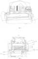
FIG. 1 is a structural diagram of a feeding device provided by an embodiment of the present invention; andFIG. 2 is a structural diagram of a temperature adjusting device provided by an embodiment of the present invention.- The technical solutions in the embodiments of the present invention will be clearly and completely described below in conjunction with the accompanying drawings in the embodiments of the present invention. Apparently, the embodiments described are some rather than all of the embodiments of the present invention. On the basis of the embodiments of the present invention, all the other embodiments obtained by those of ordinary skill in the art without creative efforts shall fall within the scope of protection of the present invention.
- As shown in
FIG. 1 , an embodiment of the present invention provides a feeding device. The feeding device may be understood as a device for delivering a resin liquid. The temperature of the resin liquid delivered by the feeding device is constant, which can improve the 3D printing effect. - The feeding device includes a first connecting pipe 11, a second connecting pipe 12, a feeding power unit 13, a
temperature adjusting device 14 and aresin vat 10 containing a resin liquid. - The
temperature adjusting device 14 includes aheat exchange pipeline 143, a liquid intake end of theheat exchange pipeline 143 is connected to a first end of the first connecting pipe 11, a liquid output end of theheat exchange pipeline 143 is connected to a first end of the second connecting pipe 12, a second end of the first connecting pipe 11 and a second end of the second connecting pipe 12 are both located in theresin vat 10, and at least one of the first connecting pipe 11 and the second connecting pipe 12 is provided with the feeding power unit 13. - The application principle of this embodiment is that when the temperature of the resin liquid in the
resin vat 10 is higher than a preset temperature, the feeding power unit 13 delivers the resin liquid from theresin vat 10 to the liquid intake end of theheat exchange pipeline 143 through the first connecting pipe 11 to cool the resin liquid, and the cooled resin liquid is delivered to the second connecting pipe 12 through the liquid output end of theheat exchange pipeline 143 and flows through the second connecting pipe 12 back to theresin vat 10, thereby realizing a reduction of the temperature of the resin liquid in theresin vat 10. - When the temperature of the resin liquid in the
resin vat 10 is lower than the preset temperature, the feeding power unit 13 delivers the resin liquid from theresin vat 10 to the liquid intake end of theheat exchange pipeline 143 through the first connecting pipe 11 to heat the resin liquid, and the heated resin liquid is delivered to the second connecting pipe 12 through the liquid output end of theheat exchange pipeline 143 and flows through the second connecting pipe 12 back to theresin vat 10, thereby realizing an increase in the temperature of the resin liquid in theresin vat 10. Optionally, the preset temperature is set to 40 degrees, or the preset temperature is set as a temperature range. - Optionally, the first connecting pipe 11 is provided with the feeding power unit 13, or the second connecting pipe 12 is provided with the feeding power unit 13, or the first connecting pipe 11 and the second connecting pipe 12 are each provided with the feeding power unit 13, which is not specifically limited in this embodiment.
- Further, the feeding device further includes a
temperature sensor 101 provided at an outer wall of theresin vat 10. - Optionally, the
temperature sensor 101 may be provided at an outer bottom of theresin vat 10, and the above-mentionedtemperature sensor 101 is configured to detect the temperature of the resin liquid in theresin vat 10. - Further, the feeding device further includes a controller in communication connection with the
temperature sensor 101 and the feeding power unit 13. The controller is configured to obtain the temperature detected by thetemperature sensor 101. When the temperature of the resin liquid is higher than the preset temperature, the feeding power unit 13 is driven. When the temperature of the resin liquid is lower than the preset temperature, the feeding power unit 13 is driven. - Optionally, the controller may be a main control board inside the 3D printer, or may be a circuit board or other electronics that are independently provided. The controller drives, based on the temperature detected by the
temperature sensor 101, the feeding power unit 13 to work, in order to cool or heat the resin liquid. - In the embodiments of the present invention, when the temperature of the resin liquid is higher than a preset temperature, the feeding power unit 13 delivers the resin liquid from the
resin vat 10 to theheat exchange pipeline 143 through the first connecting pipe 11 to cool the resin liquid to obtain a cooled resin liquid, and delivers the cooled resin liquid back to theresin vat 10 through the second connecting pipe 12, when the temperature of the resin liquid is lower than the preset temperature, the feeding power unit 13 delivers the resin liquid from theresin vat 10 to theheat exchange pipeline 143 through the first connecting pipe 11 to heat the resin liquid to obtain a heated resin liquid, and delivers the heated resin liquid back to theresin vat 10 through the second connecting pipe 12. That is, when the temperature of the resin liquid is higher than a preset temperature, the resin liquid is cooled to reduce the temperature of the resin liquid, when the temperature of the resin liquid is lower than the preset temperature, the resin liquid is heated to increase the temperature of the resin liquid. In this way, the temperature of the resin liquid in theresin vat 10 is controlled to be within an ideal temperature range, thereby improving the printing effect. - Further, the feeding power unit 13 includes a
first water pump 41 provided at an outer wall of theresin vat 10, theheat exchange pipeline 143 includes a firstheat exchange sub-pipeline 1431, the first connecting pipe 11 includes a first connecting sub-pipe 21 and a second connecting sub-pipe 22, and the second connecting pipe 12 includes a third connectingsub-pipe 31. A first end of the first connecting sub-pipe 21 is located in theresin vat 10, and a second end of the first connecting sub-pipe 21 is connected to a liquid intake end of thefirst water pump 41. A first end of the second connecting sub-pipe 22 is connected to a liquid output end of thefirst water pump 41, and a second end of the second connecting sub-pipe 22 is connected to a liquid intake end of the firstheat exchange sub-pipeline 1431. A first end of the third connectingsub-pipe 31 is connected to a liquid output end of the firstheat exchange sub-pipeline 1431, and a second end of the third connectingsub-pipe 31 is located in theresin vat 10. - Further, the
temperature adjusting device 14 includes arefrigeration module 141. Therefrigeration module 141 includes acooling block 51 and arefrigeration component 1411. Thecooling block 51 is provided on a first side of the firstheat exchange sub-pipeline 1431, and therefrigeration component 1411 is provided on a second side of the firstheat exchange sub-pipeline 1431. - Referring to
FIG. 2 , in the invention thetemperature adjusting device 14 includes arefrigeration module 141. Therefrigeration module 141 includes acooling block 51 and arefrigeration component 1411. A firstheat exchange sub-pipeline 1431 is provided between the coolingblock 51 and therefrigeration component 1411, and the firstheat exchange sub-pipeline 1431 is attached to therefrigeration component 1411 and thecooling block 51. In this way, when the resin liquid circulates in the firstheat exchange sub-pipeline 1431, thecooling block 51 and therefrigeration component 1411 cool the resin liquid flowing in the firstheat exchange sub-pipeline 1431. - The feeding power unit 13 includes the
first water pump 41. When the temperature of the resin liquid is higher than the preset temperature, the controller drives thefirst water pump 41, thefirst water pump 41 pumps the resin liquid from theresin vat 10 to deliver the resin liquid to the firstheat exchange sub-pipeline 1431 such that the resin liquid is cooled, and the resin liquid with a reduced temperature flows back to theresin vat 10 through the third connectingsub-pipe 31, thereby realizing a reduction of the temperature of the resin liquid in theresin vat 10. - Further, the
refrigeration component 1411 includes a refrigeration side of asemiconductor 52, and thesemiconductor 52 is composed of at least two different semiconductor materials. - In this embodiment, one optional way is that the
refrigeration component 1411 may be the refrigeration side of thesemiconductor 52. Thesemiconductor 52 may be a refrigeration sheet, which may be composed of at least two different semiconductor materials. In this way, when the refrigeration sheet is powered on, a first side of the refrigeration sheet absorbs heat to realize a cooling effect, and this side is called a refrigeration side of the refrigeration sheet; and a second side of the refrigeration sheet releases heat to realize a heating effect, and this side is called a heating side. - Another optional way is that the
refrigeration component 1411 may also be other components that can achieve a refrigeration effect, and this embodiment will not be described in detail by way of example herein. - Further, the feeding power unit 13 includes a
second water pump 42 provided at the outer wall of theresin vat 10, theheat exchange pipeline 143 includes a secondheat exchange sub-pipeline 1432, the first connecting pipe 11 includes a fourth connecting sub-pipe 23 and a fifth connecting sub-pipe 24, and the second connecting pipe 12 includes a sixth connecting sub-pipe 32. A first end of the fourth connecting sub-pipe 23 is located in theresin vat 10, and a second end of the fourth connecting sub-pipe 23 is connected to a liquid intake end of thesecond water pump 42. A first end of the fifth connecting sub-pipe 24 is connected to a liquid output end of thesecond water pump 42, and a second end of the fifth connecting sub-pipe 24 is connected to a liquid intake end of the secondheat exchange sub-pipeline 1432. A first end of the sixth connecting sub-pipe 32 is connected to a liquid output end of the secondheat exchange sub-pipeline 1432, and a second end of the sixth connecting sub-pipe 32 is located in theresin vat 10. - Further, the
temperature adjusting device 14 includes aheating module 142. Theheating module 142 includes aheat sink 53, afan 54 and a heating component 55. The heating component 55 is provided on a first side of the secondheat exchange sub-pipeline 1432, theheat sink 53 is provided on a second side of the secondheat exchange sub-pipeline 1432, thefan 54 is provided on a side of theheat sink 53 away from the secondheat exchange sub-pipeline 1432, and the side of theheat sink 53 away from the secondheat exchange sub-pipeline 1432 has a relief shape. - Referring to
FIG. 2 , in the invention thetemperature adjusting device 14 includes aheating module 142. Theheating module 142 includes aheat sink 53, afan 54 and a heating component 55. A secondheat exchange sub-pipeline 1432 is provided between theheat sink 53 and the heating component 55, and the secondheat exchange sub-pipeline 1432 is attached to theheat sink 53 and the heating component 55. In this way, when the resin liquid circulates in the secondheat exchange sub-pipeline 1432, theheat sink 53 and the heating component 55 heat the resin liquid flowing in the secondheat exchange sub-pipeline 1432. - As shown in
FIG. 2 , thefan 54 is further provided on the side of theheat sink 53 away from the secondheat exchange sub-pipeline 1432, thefan 54 is configured to dissipate heat from theheat sink 53 to prevent the temperature of the resin liquid in the secondheat exchange sub-pipeline 1432 being too high, thereby reducing the printing effect. - The feeding power unit 13 includes a
second water pump 42. When the temperature of the resin liquid is lower than the preset temperature, the controller drives thesecond water pump 42, thesecond water pump 42 pumps the resin liquid from theresin vat 10 to deliver the resin liquid to the secondheat exchange sub-pipeline 1432 such that the resin liquid is heated, the resin liquid with an increased temperature flows back to theresin vat 10 through the sixth connecting sub-pipe 32, thereby realizing an increase in the temperature of the resin liquid in theresin vat 10. - Further, the heating component 55 includes a
heating side 521 of asemiconductor 52, and thesemiconductor 52 is composed of at least two different semiconductor materials. - In this embodiment, one optional way is that the heating component 55 may be the
heating side 521 of thesemiconductor 52. Thesemiconductor 52 may be a refrigeration sheet, which may be composed of at least two different semiconductor materials. In this way, when the refrigeration sheet is powered on, a first side of the refrigeration sheet absorbs heat to realize a cooling effect, and this side is called a refrigeration side of the refrigeration sheet; and a second side of the refrigeration sheet releases heat to realize a heating effect, and this side is called a heating side. - Another optional way is that the heating component 55 may also be other components that can achieve a heating effect, and this embodiment will not be described in detail by way of example herein.
- In one embodiment, the controller may be installed with embedded software that can use a proportional integral differential (PID) algorithm to drive, according to the temperature detected by the
temperature sensor 101, thefirst water pump 41 and thesecond water pump 42 to work at the same time. In this case, part of the resin liquid in theresin vat 10 is pumped by thefirst water pump 41 to the firstheat exchange sub-pipeline 1431 for being subjected to cooling, and part of the resin liquid in theresin vat 10 is pumped bysecond water pump 42 to the secondheat exchange sub-pipeline 1432 for being subjected to heating. With the PID algorithm, the controller controls, according to the preset temperature and the temperature of the resin liquid detected by thetemperature sensor 101, the power of thefirst water pump 41 to limit the flow rate of the resin liquid for being subjected to cooling, and the power of thesecond water pump 42 to limit the flow rate of the resin liquid for being subjected to heating, such that the temperature of the resin liquid reaches the preset temperature. - An embodiment of the present invention further provides a 3D printer. The 3D printer includes the feeding device as described above, and the structure of the feeding device can refer to the above embodiments, and the details are not repeated herein. In this embodiment, since the feeding device in the above embodiments is adopted, the 3D printer provided in the embodiment of the present invention has the same beneficial effects as those of the feeding device in the above embodiments.
- The scope of protection of the present invention shall be subject to the scope of protection of the claims.
Claims (13)
- A feeding device for a stereoscopic 3D printer, comprising:a first connecting pipe (11);a second connecting pipe (12);a feeding power unit (13);a temperature adjusting device (14); anda resin vat (10) arranged to contain resin liquid;wherein the temperature adjusting device (14) comprises a heat exchange pipeline (143), a liquid intake end of the heat exchange pipeline (143) is connected to a first end of the first connecting pipe (11), a liquid output end of the heat exchange pipeline (143) is connected to a first end of the second connecting pipe (12), a second end of the first connecting pipe (11) and a second end of the second connecting pipe (12) are both located in the resin vat (10), at least one of the first connecting pipe (11) and the second connecting pipe (12) is provided with the feeding power unit (13); andwhen a temperature of the resin liquid is higher than a preset temperature, the feeding power unit (13) is configured to deliver the resin liquid from the resin vat (10) to a first heat exchange sub-pipeline (1431) of the heat exchange pipeline (143) through the first connecting pipe (11) to cool the resin liquid to obtain a cooled resin liquid, and is configured to deliver the cooled resin liquid back to the resin vat (10) through the second connecting pipe (12), when the temperature of the resin liquid is lower than the preset temperature, the feeding power unit (13) is configured to deliver the resin liquid from the resin vat (10) to a second heat exchange sub-pipeline (1432) of the heat exchange pipeline (143) through the first connecting pipe (11) to heat the resin liquid to obtain a heated resin liquid, and is configured to deliver the heated resin liquid back to the resin vat (10) through the second connecting pipe (12);wherein the temperature adjusting device (14) further comprises a heating module (142) and a refrigeration module (141);wherein the refrigeration module (141) comprises a cooling block (51) and a refrigeration component (1411), the first heat exchange sub-pipeline (1431) is provided between the cooling block (51) and the refrigeration component (1411), and the first heat exchange sub-pipeline (1431) is attached to the refrigeration component (1411) and the cooling block (51), so that when the resin liquid circulates in the first heat exchange sub-pipeline (1431), the cooling block (51) and the refrigeration component (1411) cool the resin liquid flowing in the first heat exchange sub-pipeline (1431); andwherein the heating module (142) comprises a heat sink (53), a fan (54) and a heating component (55), the second heat exchange sub-pipeline (1432) is provided between the heat sink (53) and the heating component (55), and the second heat exchange sub-pipeline (1432) is attached to the heat sink (53) and the heating component (55), so that when the resin liquid circulates in the second heat exchange sub-pipeline (1432), the heat sink (53) and the heating component (55) heat the resin liquid flowing in the second heat exchange sub-pipeline (1432).
- The feeding device according to claim 1, wherein the feeding power unit (13) comprises a first water pump (41) provided at an outer wall of the resin vat (10), the first connecting pipe (11) comprises a first connecting sub-pipe (21) and a second connecting sub-pipe (22), and the second connecting pipe (12) comprises a third connecting sub-pipe (31);a first end of the first connecting sub-pipe (21) is located in the resin vat (10), and a second end of the first connecting sub-pipe (21) is connected to a liquid intake end of the first water pump (41);a first end of the second connecting sub-pipe (22) is connected to a liquid output end of the first water pump (41), and a second end of the second connecting sub-pipe (22) is connected to the liquid intake end of the first heat exchange sub-pipeline (1431); anda first end of the third connecting sub-pipe (31) is connected to a liquid output end of the first heat exchange sub-pipeline (1431), and a second end of the third connecting sub-pipe (31) is located in the resin vat (10).
- The feeding device according to claim 1, wherein the refrigeration component (1411) comprises a refrigeration side of a semiconductor (52), and the semiconductor (52) is composed of at least two different semiconductor materials.
- The feeding device according to claim 2, wherein the feeding power unit (13) comprises a second water pump (42) provided at an outer wall of the resin vat (10), the first connecting pipe (11) comprises a fourth connecting sub-pipe (23) and a fifth connecting sub-pipe (24), and the second connecting pipe (12) comprises a sixth connecting sub-pipe (32);a first end of the fourth connecting sub-pipe (23) is located in the resin vat (10), and a second end of the fourth connecting sub-pipe (23) is connected to a liquid intake end of the second water pump (42);a first end of the fifth connecting sub-pipe (24) is connected to a liquid output end of the second water pump (42), and a second end of the fifth connecting sub-pipe (24) is connected to a liquid intake end of the second heat exchange sub-pipeline (1432); anda first end of the sixth connecting sub-pipe (32) is connected to a liquid output end of the second heat exchange sub-pipeline (1432), and a second end of the sixth connecting sub-pipe (32) is located in the resin vat (10).
- The feeding device according to claim 1, wherein the fan (54) is provided on a side of the heat sink (53) away from the second heat exchange sub-pipeline (1432), and the side of the heat sink (53) away from the second heat exchange sub-pipeline (1432) has a relief shape.
- The feeding device according to claim 5, wherein the heating component (55) comprises a heating side of a semiconductor (52), and the semiconductor (52) is composed of at least two different semiconductor materials.
- The feeding device according to claim 1, wherein the feeding device further comprises a temperature sensor (101) provided at an outer wall of the resin vat (10), wherein
the temperature sensor (101) is configured to detect the temperature of the resin liquid in the resin vat (10). - A stereoscopic 3D printer, comprising a feeding device according to claim 1.
- The stereoscopic 3D printer according to claim 8, wherein the feeding power unit (13) comprises a first water pump (41) provided at an outer wall of the resin vat (10), the first connecting pipe (11) comprises a first connecting sub-pipe (21) and a second connecting sub-pipe (22), and the second connecting pipe (12) comprises a third connecting sub-pipe (31);a first end of the first connecting sub-pipe (21) is located in the resin vat (10), and a second end of the first connecting sub-pipe (21) is connected to a liquid intake end of the first water pump (41);a first end of the second connecting sub-pipe (22) is connected to a liquid output end of the first water pump (41), and a second end of the second connecting sub-pipe (22) is connected to a liquid intake end of the first heat exchange sub-pipeline (1431); anda first end of the third connecting sub-pipe (31) is connected to a liquid output end of the first heat exchange sub-pipeline (1431), and a second end of the third connecting sub-pipe (31) is located in the resin vat (10).
- The stereoscopic 3D printer according to claim 8, wherein the refrigeration component (1411) comprises a refrigeration side of a semiconductor (52), and the semiconductor (52) is composed of at least two different semiconductor materials.
- The stereoscopic 3D printer according to claim 9, wherein the feeding power unit (13) comprises a second water pump (42) provided at an outer wall of the resin vat (10), the first connecting pipe (11) comprises a fourth connecting sub-pipe (23) and a fifth connecting sub-pipe (24), and the second connecting pipe (12) comprises a sixth connecting sub-pipe (32);a first end of the fourth connecting sub-pipe (23) is located in the resin vat (10), and a second end of the fourth connecting sub-pipe (23) is connected to a liquid intake end of the second water pump (42);a first end of the fifth connecting sub-pipe (24) is connected to a liquid output end of the second water pump (42), and a second end of the fifth connecting sub-pipe (24) is connected to a liquid intake end of the second heat exchange sub-pipeline (1432); anda first end of the sixth connecting sub-pipe (32) is connected to a liquid output end of the second heat exchange sub-pipeline (1432), and a second end of the sixth connecting sub-pipe (32) is located in the resin vat (10).
- The stereoscopic 3D printer according to claim 8, wherein the fan (54) is provided on a side of the heat sink (53) away from the second heat exchange sub-pipeline (1432), and the side of the heat sink (53) away from the second heat exchange sub-pipeline (1432) has a relief shape.
- The stereoscopic 3D printer according to claim 8, wherein the heating component (55) comprises a heating side of a semiconductor (52), and the semiconductor (52) is composed of at least two different semiconductor materials.
Applications Claiming Priority (1)
| Application Number | Priority Date | Filing Date | Title |
|---|---|---|---|
| CN202011210454.3ACN112477134B (en) | 2020-11-03 | 2020-11-03 | Material feeding unit and 3D printer |
Publications (3)
| Publication Number | Publication Date |
|---|---|
| EP3991944A1 EP3991944A1 (en) | 2022-05-04 |
| EP3991944B1true EP3991944B1 (en) | 2024-04-17 |
| EP3991944C0 EP3991944C0 (en) | 2024-04-17 |
Family
ID=74927823
Family Applications (1)
| Application Number | Title | Priority Date | Filing Date |
|---|---|---|---|
| EP21201753.7AActiveEP3991944B1 (en) | 2020-11-03 | 2021-10-08 | Feeding device for a stereoscopic 3d printer and 3d printer |
Country Status (3)
| Country | Link |
|---|---|
| US (1) | US11660816B2 (en) |
| EP (1) | EP3991944B1 (en) |
| CN (1) | CN112477134B (en) |
Families Citing this family (1)
| Publication number | Priority date | Publication date | Assignee | Title |
|---|---|---|---|---|
| CN115071131B (en)* | 2022-06-14 | 2024-03-19 | 江苏大学 | A device and printing process for reducing the viscosity of photosensitive resin based on the magnetocaloric effect |
Family Cites Families (13)
| Publication number | Priority date | Publication date | Assignee | Title |
|---|---|---|---|---|
| US6401462B1 (en)* | 2000-03-16 | 2002-06-11 | George Bielinski | Thermoelectric cooling system |
| JP4114595B2 (en) | 2003-10-30 | 2008-07-09 | Jsr株式会社 | Stereolithography method |
| CN105122135B (en) | 2013-02-12 | 2020-03-20 | 卡本有限公司 | Continuous liquid mesophase printing |
| US10259171B2 (en) | 2014-04-25 | 2019-04-16 | Carbon, Inc. | Continuous three dimensional fabrication from immiscible liquids |
| WO2017113190A1 (en)* | 2015-12-30 | 2017-07-06 | 四川蓝光英诺生物科技股份有限公司 | Bioprinter temperature control system and bioprinter |
| US11497275B2 (en)* | 2017-02-27 | 2022-11-15 | Kornit Digital Technologies Ltd. | 3D printed articles of footwear with particles |
| WO2018208799A1 (en)* | 2017-05-08 | 2018-11-15 | Paxis Llc | Additive manufacturing apparatus, system, and method |
| US11203156B2 (en) | 2018-08-20 | 2021-12-21 | NEXA3D Inc. | Methods and systems for photo-curing photo-sensitive material for printing and other applications |
| WO2020117490A1 (en)* | 2018-12-03 | 2020-06-11 | Carbon, Inc. | Window thermal profile calibration in additive manufacturing |
| CN109532002A (en) | 2018-12-28 | 2019-03-29 | 北京金达雷科技有限公司 | Photocuring 3D printer |
| CA3127638A1 (en)* | 2019-01-23 | 2020-07-30 | Jk-Holding Gmbh | Dual heating or cooling system and its use |
| CN110936609A (en)* | 2019-11-30 | 2020-03-31 | 共享智能铸造产业创新中心有限公司 | Printing head, printing method, printing system, storage medium, and printing apparatus |
| WO2022090321A1 (en)* | 2020-10-28 | 2022-05-05 | Regenhu Ag | Temperature-regulated additive manufacturing |
- 2020
- 2020-11-03CNCN202011210454.3Apatent/CN112477134B/enactiveActive
- 2021
- 2021-09-29USUS17/449,267patent/US11660816B2/enactiveActive
- 2021-10-08EPEP21201753.7Apatent/EP3991944B1/enactiveActive
Also Published As
| Publication number | Publication date |
|---|---|
| CN112477134A (en) | 2021-03-12 |
| EP3991944A1 (en) | 2022-05-04 |
| US20220134664A1 (en) | 2022-05-05 |
| US11660816B2 (en) | 2023-05-30 |
| CN112477134B (en) | 2023-01-06 |
| EP3991944C0 (en) | 2024-04-17 |
Similar Documents
| Publication | Publication Date | Title |
|---|---|---|
| US10271457B2 (en) | Heat dissipation apparatus, heat dissipation control method, and controller | |
| WO2017113190A1 (en) | Bioprinter temperature control system and bioprinter | |
| CN107396599A (en) | A kind of heat abstractor and thermal management algorithm of movable cabinet level server system | |
| EP3991944B1 (en) | Feeding device for a stereoscopic 3d printer and 3d printer | |
| CN207040117U (en) | A cooling device for a mobile rack-level server system | |
| TW200526913A (en) | Liquid circulation type cooling system | |
| CN110412541A (en) | Liquid cooling apparatus, laser radar system and vehicle for laser radar | |
| CN215910868U (en) | Temperature control system of immersed liquid cooling heat dissipation device | |
| CN110762084A (en) | Hydraulic system and pumping machine | |
| CN102638956A (en) | Temperature equalizing system of electric equipment conducting heat by fluid jet flow | |
| CN109729704A (en) | A multi-medium liquid cooling system | |
| CN216861131U (en) | Temperature control system, arithmetic device, and autonomous vehicle | |
| CN111816892A (en) | Control system and method for quickly establishing thermal management water pressure of hydrogen fuel cell automobile | |
| CN205068278U (en) | Radiator system of computer | |
| CN108458094B (en) | Driving system of milling wheel and slot milling machine | |
| CN109799854B (en) | Cooling device and control method thereof | |
| CN104394677B (en) | It is a kind of to carry blower fan, the big power consumption air environment air-cooled case of air quantity be distributed | |
| US20160286689A1 (en) | Cooling method for a 3D IC computer system | |
| CN110190039A (en) | Water-water heat exchange liquid cooling system and its liquid cooling source supply liquid temperature and flow control method | |
| CN101977489A (en) | Cooling device and method for heating elements | |
| CN214482026U (en) | Water belt type water cooling plate with accurate temperature control function | |
| CN222351075U (en) | Hydraulic oil heat abstractor and hydraulic equipment | |
| CN219549269U (en) | Hydraulic heat dissipation control system and engineering vehicle | |
| JP6983429B2 (en) | Auxiliary device that produces a temperature rise / fall effect on machine tool members via a 4-way solenoid valve | |
| CN217944837U (en) | Thermal management system and vehicle |
Legal Events
| Date | Code | Title | Description |
|---|---|---|---|
| PUAI | Public reference made under article 153(3) epc to a published international application that has entered the european phase | Free format text:ORIGINAL CODE: 0009012 | |
| STAA | Information on the status of an ep patent application or granted ep patent | Free format text:STATUS: THE APPLICATION HAS BEEN PUBLISHED | |
| AK | Designated contracting states | Kind code of ref document:A1 Designated state(s):AL AT BE BG CH CY CZ DE DK EE ES FI FR GB GR HR HU IE IS IT LI LT LU LV MC MK MT NL NO PL PT RO RS SE SI SK SM TR | |
| STAA | Information on the status of an ep patent application or granted ep patent | Free format text:STATUS: REQUEST FOR EXAMINATION WAS MADE | |
| 17P | Request for examination filed | Effective date:20220928 | |
| RBV | Designated contracting states (corrected) | Designated state(s):AL AT BE BG CH CY CZ DE DK EE ES FI FR GB GR HR HU IE IS IT LI LT LU LV MC MK MT NL NO PL PT RO RS SE SI SK SM TR | |
| STAA | Information on the status of an ep patent application or granted ep patent | Free format text:STATUS: EXAMINATION IS IN PROGRESS | |
| 17Q | First examination report despatched | Effective date:20230522 | |
| GRAP | Despatch of communication of intention to grant a patent | Free format text:ORIGINAL CODE: EPIDOSNIGR1 | |
| STAA | Information on the status of an ep patent application or granted ep patent | Free format text:STATUS: GRANT OF PATENT IS INTENDED | |
| INTG | Intention to grant announced | Effective date:20231201 | |
| GRAS | Grant fee paid | Free format text:ORIGINAL CODE: EPIDOSNIGR3 | |
| GRAA | (expected) grant | Free format text:ORIGINAL CODE: 0009210 | |
| STAA | Information on the status of an ep patent application or granted ep patent | Free format text:STATUS: THE PATENT HAS BEEN GRANTED | |
| AK | Designated contracting states | Kind code of ref document:B1 Designated state(s):AL AT BE BG CH CY CZ DE DK EE ES FI FR GB GR HR HU IE IS IT LI LT LU LV MC MK MT NL NO PL PT RO RS SE SI SK SM TR | |
| REG | Reference to a national code | Ref country code:GB Ref legal event code:FG4D | |
| REG | Reference to a national code | Ref country code:CH Ref legal event code:EP | |
| REG | Reference to a national code | Ref country code:DE Ref legal event code:R096 Ref document number:602021011876 Country of ref document:DE | |
| REG | Reference to a national code | Ref country code:IE Ref legal event code:FG4D | |
| U01 | Request for unitary effect filed | Effective date:20240424 | |
| U07 | Unitary effect registered | Designated state(s):AT BE BG DE DK EE FI FR IT LT LU LV MT NL PT SE SI Effective date:20240503 | |
| PG25 | Lapsed in a contracting state [announced via postgrant information from national office to epo] | Ref country code:IS Free format text:LAPSE BECAUSE OF FAILURE TO SUBMIT A TRANSLATION OF THE DESCRIPTION OR TO PAY THE FEE WITHIN THE PRESCRIBED TIME-LIMIT Effective date:20240817 | |
| PG25 | Lapsed in a contracting state [announced via postgrant information from national office to epo] | Ref country code:HR Free format text:LAPSE BECAUSE OF FAILURE TO SUBMIT A TRANSLATION OF THE DESCRIPTION OR TO PAY THE FEE WITHIN THE PRESCRIBED TIME-LIMIT Effective date:20240417 | |
| PG25 | Lapsed in a contracting state [announced via postgrant information from national office to epo] | Ref country code:GR Free format text:LAPSE BECAUSE OF FAILURE TO SUBMIT A TRANSLATION OF THE DESCRIPTION OR TO PAY THE FEE WITHIN THE PRESCRIBED TIME-LIMIT Effective date:20240718 | |
| PG25 | Lapsed in a contracting state [announced via postgrant information from national office to epo] | Ref country code:ES Free format text:LAPSE BECAUSE OF FAILURE TO SUBMIT A TRANSLATION OF THE DESCRIPTION OR TO PAY THE FEE WITHIN THE PRESCRIBED TIME-LIMIT Effective date:20240417 | |
| PG25 | Lapsed in a contracting state [announced via postgrant information from national office to epo] | Ref country code:PL Free format text:LAPSE BECAUSE OF FAILURE TO SUBMIT A TRANSLATION OF THE DESCRIPTION OR TO PAY THE FEE WITHIN THE PRESCRIBED TIME-LIMIT Effective date:20240417 | |
| PG25 | Lapsed in a contracting state [announced via postgrant information from national office to epo] | Ref country code:PL Free format text:LAPSE BECAUSE OF FAILURE TO SUBMIT A TRANSLATION OF THE DESCRIPTION OR TO PAY THE FEE WITHIN THE PRESCRIBED TIME-LIMIT Effective date:20240417 Ref country code:NO Free format text:LAPSE BECAUSE OF FAILURE TO SUBMIT A TRANSLATION OF THE DESCRIPTION OR TO PAY THE FEE WITHIN THE PRESCRIBED TIME-LIMIT Effective date:20240717 Ref country code:IS Free format text:LAPSE BECAUSE OF FAILURE TO SUBMIT A TRANSLATION OF THE DESCRIPTION OR TO PAY THE FEE WITHIN THE PRESCRIBED TIME-LIMIT Effective date:20240817 Ref country code:HR Free format text:LAPSE BECAUSE OF FAILURE TO SUBMIT A TRANSLATION OF THE DESCRIPTION OR TO PAY THE FEE WITHIN THE PRESCRIBED TIME-LIMIT Effective date:20240417 Ref country code:GR Free format text:LAPSE BECAUSE OF FAILURE TO SUBMIT A TRANSLATION OF THE DESCRIPTION OR TO PAY THE FEE WITHIN THE PRESCRIBED TIME-LIMIT Effective date:20240718 Ref country code:ES Free format text:LAPSE BECAUSE OF FAILURE TO SUBMIT A TRANSLATION OF THE DESCRIPTION OR TO PAY THE FEE WITHIN THE PRESCRIBED TIME-LIMIT Effective date:20240417 Ref country code:RS Free format text:LAPSE BECAUSE OF FAILURE TO SUBMIT A TRANSLATION OF THE DESCRIPTION OR TO PAY THE FEE WITHIN THE PRESCRIBED TIME-LIMIT Effective date:20240717 | |
| U20 | Renewal fee for the european patent with unitary effect paid | Year of fee payment:4 Effective date:20240927 | |
| REG | Reference to a national code | Ref country code:DE Ref legal event code:R097 Ref document number:602021011876 Country of ref document:DE | |
| PG25 | Lapsed in a contracting state [announced via postgrant information from national office to epo] | Ref country code:CZ Free format text:LAPSE BECAUSE OF FAILURE TO SUBMIT A TRANSLATION OF THE DESCRIPTION OR TO PAY THE FEE WITHIN THE PRESCRIBED TIME-LIMIT Effective date:20240417 | |
| PG25 | Lapsed in a contracting state [announced via postgrant information from national office to epo] | Ref country code:SK Free format text:LAPSE BECAUSE OF FAILURE TO SUBMIT A TRANSLATION OF THE DESCRIPTION OR TO PAY THE FEE WITHIN THE PRESCRIBED TIME-LIMIT Effective date:20240417 Ref country code:RO Free format text:LAPSE BECAUSE OF FAILURE TO SUBMIT A TRANSLATION OF THE DESCRIPTION OR TO PAY THE FEE WITHIN THE PRESCRIBED TIME-LIMIT Effective date:20240417 | |
| PG25 | Lapsed in a contracting state [announced via postgrant information from national office to epo] | Ref country code:SM Free format text:LAPSE BECAUSE OF FAILURE TO SUBMIT A TRANSLATION OF THE DESCRIPTION OR TO PAY THE FEE WITHIN THE PRESCRIBED TIME-LIMIT Effective date:20240417 | |
| PG25 | Lapsed in a contracting state [announced via postgrant information from national office to epo] | Ref country code:SM Free format text:LAPSE BECAUSE OF FAILURE TO SUBMIT A TRANSLATION OF THE DESCRIPTION OR TO PAY THE FEE WITHIN THE PRESCRIBED TIME-LIMIT Effective date:20240417 Ref country code:SK Free format text:LAPSE BECAUSE OF FAILURE TO SUBMIT A TRANSLATION OF THE DESCRIPTION OR TO PAY THE FEE WITHIN THE PRESCRIBED TIME-LIMIT Effective date:20240417 Ref country code:RO Free format text:LAPSE BECAUSE OF FAILURE TO SUBMIT A TRANSLATION OF THE DESCRIPTION OR TO PAY THE FEE WITHIN THE PRESCRIBED TIME-LIMIT Effective date:20240417 Ref country code:CZ Free format text:LAPSE BECAUSE OF FAILURE TO SUBMIT A TRANSLATION OF THE DESCRIPTION OR TO PAY THE FEE WITHIN THE PRESCRIBED TIME-LIMIT Effective date:20240417 | |
| PLBE | No opposition filed within time limit | Free format text:ORIGINAL CODE: 0009261 | |
| STAA | Information on the status of an ep patent application or granted ep patent | Free format text:STATUS: NO OPPOSITION FILED WITHIN TIME LIMIT | |
| 26N | No opposition filed | Effective date:20250120 | |
| REG | Reference to a national code | Ref country code:CH Ref legal event code:PL | |
| PG25 | Lapsed in a contracting state [announced via postgrant information from national office to epo] | Ref country code:MC Free format text:LAPSE BECAUSE OF FAILURE TO SUBMIT A TRANSLATION OF THE DESCRIPTION OR TO PAY THE FEE WITHIN THE PRESCRIBED TIME-LIMIT Effective date:20240417 | |
| PG25 | Lapsed in a contracting state [announced via postgrant information from national office to epo] | Ref country code:CH Free format text:LAPSE BECAUSE OF NON-PAYMENT OF DUE FEES Effective date:20241031 |