EP3991764B1 - Flowmeter for proportioning water in dialysis system - Google Patents
Flowmeter for proportioning water in dialysis systemDownload PDFInfo
- Publication number
- EP3991764B1 EP3991764B1EP20203997.0AEP20203997AEP3991764B1EP 3991764 B1EP3991764 B1EP 3991764B1EP 20203997 AEP20203997 AEP 20203997AEP 3991764 B1EP3991764 B1EP 3991764B1
- Authority
- EP
- European Patent Office
- Prior art keywords
- fluid
- valve
- controller
- coupled
- flowmeter
- Prior art date
- Legal status (The legal status is an assumption and is not a legal conclusion. Google has not performed a legal analysis and makes no representation as to the accuracy of the status listed.)
- Active
Links
Images

Classifications
- A—HUMAN NECESSITIES
- A61—MEDICAL OR VETERINARY SCIENCE; HYGIENE
- A61M—DEVICES FOR INTRODUCING MEDIA INTO, OR ONTO, THE BODY; DEVICES FOR TRANSDUCING BODY MEDIA OR FOR TAKING MEDIA FROM THE BODY; DEVICES FOR PRODUCING OR ENDING SLEEP OR STUPOR
- A61M1/00—Suction or pumping devices for medical purposes; Devices for carrying-off, for treatment of, or for carrying-over, body-liquids; Drainage systems
- A61M1/36—Other treatment of blood in a by-pass of the natural circulatory system, e.g. temperature adaptation, irradiation ; Extra-corporeal blood circuits
- A61M1/3621—Extra-corporeal blood circuits
- A61M1/3626—Gas bubble detectors
- A—HUMAN NECESSITIES
- A61—MEDICAL OR VETERINARY SCIENCE; HYGIENE
- A61M—DEVICES FOR INTRODUCING MEDIA INTO, OR ONTO, THE BODY; DEVICES FOR TRANSDUCING BODY MEDIA OR FOR TAKING MEDIA FROM THE BODY; DEVICES FOR PRODUCING OR ENDING SLEEP OR STUPOR
- A61M1/00—Suction or pumping devices for medical purposes; Devices for carrying-off, for treatment of, or for carrying-over, body-liquids; Drainage systems
- A61M1/14—Dialysis systems; Artificial kidneys; Blood oxygenators ; Reciprocating systems for treatment of body fluids, e.g. single needle systems for hemofiltration or pheresis
- A61M1/16—Dialysis systems; Artificial kidneys; Blood oxygenators ; Reciprocating systems for treatment of body fluids, e.g. single needle systems for hemofiltration or pheresis with membranes
- A61M1/1601—Control or regulation
- A61M1/1603—Regulation parameters
- A61M1/1605—Physical characteristics of the dialysate fluid
- A61M1/1607—Physical characteristics of the dialysate fluid before use, i.e. upstream of dialyser
- A—HUMAN NECESSITIES
- A61—MEDICAL OR VETERINARY SCIENCE; HYGIENE
- A61M—DEVICES FOR INTRODUCING MEDIA INTO, OR ONTO, THE BODY; DEVICES FOR TRANSDUCING BODY MEDIA OR FOR TAKING MEDIA FROM THE BODY; DEVICES FOR PRODUCING OR ENDING SLEEP OR STUPOR
- A61M1/00—Suction or pumping devices for medical purposes; Devices for carrying-off, for treatment of, or for carrying-over, body-liquids; Drainage systems
- A61M1/14—Dialysis systems; Artificial kidneys; Blood oxygenators ; Reciprocating systems for treatment of body fluids, e.g. single needle systems for hemofiltration or pheresis
- A61M1/16—Dialysis systems; Artificial kidneys; Blood oxygenators ; Reciprocating systems for treatment of body fluids, e.g. single needle systems for hemofiltration or pheresis with membranes
- A61M1/1601—Control or regulation
- A61M1/1615—Control or regulation using measurements made at different flow rates
- A—HUMAN NECESSITIES
- A61—MEDICAL OR VETERINARY SCIENCE; HYGIENE
- A61M—DEVICES FOR INTRODUCING MEDIA INTO, OR ONTO, THE BODY; DEVICES FOR TRANSDUCING BODY MEDIA OR FOR TAKING MEDIA FROM THE BODY; DEVICES FOR PRODUCING OR ENDING SLEEP OR STUPOR
- A61M1/00—Suction or pumping devices for medical purposes; Devices for carrying-off, for treatment of, or for carrying-over, body-liquids; Drainage systems
- A61M1/14—Dialysis systems; Artificial kidneys; Blood oxygenators ; Reciprocating systems for treatment of body fluids, e.g. single needle systems for hemofiltration or pheresis
- A61M1/16—Dialysis systems; Artificial kidneys; Blood oxygenators ; Reciprocating systems for treatment of body fluids, e.g. single needle systems for hemofiltration or pheresis with membranes
- A61M1/1654—Dialysates therefor
- A61M1/1656—Apparatus for preparing dialysates
- A61M1/1658—Degasification
- A—HUMAN NECESSITIES
- A61—MEDICAL OR VETERINARY SCIENCE; HYGIENE
- A61M—DEVICES FOR INTRODUCING MEDIA INTO, OR ONTO, THE BODY; DEVICES FOR TRANSDUCING BODY MEDIA OR FOR TAKING MEDIA FROM THE BODY; DEVICES FOR PRODUCING OR ENDING SLEEP OR STUPOR
- A61M1/00—Suction or pumping devices for medical purposes; Devices for carrying-off, for treatment of, or for carrying-over, body-liquids; Drainage systems
- A61M1/14—Dialysis systems; Artificial kidneys; Blood oxygenators ; Reciprocating systems for treatment of body fluids, e.g. single needle systems for hemofiltration or pheresis
- A61M1/16—Dialysis systems; Artificial kidneys; Blood oxygenators ; Reciprocating systems for treatment of body fluids, e.g. single needle systems for hemofiltration or pheresis with membranes
- A61M1/1654—Dialysates therefor
- A61M1/1656—Apparatus for preparing dialysates
- A61M1/1666—Apparatus for preparing dialysates by dissolving solids
- A—HUMAN NECESSITIES
- A61—MEDICAL OR VETERINARY SCIENCE; HYGIENE
- A61M—DEVICES FOR INTRODUCING MEDIA INTO, OR ONTO, THE BODY; DEVICES FOR TRANSDUCING BODY MEDIA OR FOR TAKING MEDIA FROM THE BODY; DEVICES FOR PRODUCING OR ENDING SLEEP OR STUPOR
- A61M1/00—Suction or pumping devices for medical purposes; Devices for carrying-off, for treatment of, or for carrying-over, body-liquids; Drainage systems
- A61M1/14—Dialysis systems; Artificial kidneys; Blood oxygenators ; Reciprocating systems for treatment of body fluids, e.g. single needle systems for hemofiltration or pheresis
- A61M1/28—Peritoneal dialysis ; Other peritoneal treatment, e.g. oxygenation
- A61M1/282—Operational modes
- A—HUMAN NECESSITIES
- A61—MEDICAL OR VETERINARY SCIENCE; HYGIENE
- A61M—DEVICES FOR INTRODUCING MEDIA INTO, OR ONTO, THE BODY; DEVICES FOR TRANSDUCING BODY MEDIA OR FOR TAKING MEDIA FROM THE BODY; DEVICES FOR PRODUCING OR ENDING SLEEP OR STUPOR
- A61M1/00—Suction or pumping devices for medical purposes; Devices for carrying-off, for treatment of, or for carrying-over, body-liquids; Drainage systems
- A61M1/14—Dialysis systems; Artificial kidneys; Blood oxygenators ; Reciprocating systems for treatment of body fluids, e.g. single needle systems for hemofiltration or pheresis
- A61M1/28—Peritoneal dialysis ; Other peritoneal treatment, e.g. oxygenation
- A61M1/287—Dialysates therefor
- G—PHYSICS
- G01—MEASURING; TESTING
- G01D—MEASURING NOT SPECIALLY ADAPTED FOR A SPECIFIC VARIABLE; ARRANGEMENTS FOR MEASURING TWO OR MORE VARIABLES NOT COVERED IN A SINGLE OTHER SUBCLASS; TARIFF METERING APPARATUS; MEASURING OR TESTING NOT OTHERWISE PROVIDED FOR
- G01D21/00—Measuring or testing not otherwise provided for
- G01D21/02—Measuring two or more variables by means not covered by a single other subclass
- G—PHYSICS
- G01—MEASURING; TESTING
- G01P—MEASURING LINEAR OR ANGULAR SPEED, ACCELERATION, DECELERATION, OR SHOCK; INDICATING PRESENCE, ABSENCE, OR DIRECTION, OF MOVEMENT
- G01P5/00—Measuring speed of fluids, e.g. of air stream; Measuring speed of bodies relative to fluids, e.g. of ship, of aircraft
- G01P5/24—Measuring speed of fluids, e.g. of air stream; Measuring speed of bodies relative to fluids, e.g. of ship, of aircraft by measuring the direct influence of the streaming fluid on the properties of a detecting acoustical wave
- G01P5/245—Measuring speed of fluids, e.g. of air stream; Measuring speed of bodies relative to fluids, e.g. of ship, of aircraft by measuring the direct influence of the streaming fluid on the properties of a detecting acoustical wave by measuring transit time of acoustical waves
- G—PHYSICS
- G01—MEASURING; TESTING
- G01P—MEASURING LINEAR OR ANGULAR SPEED, ACCELERATION, DECELERATION, OR SHOCK; INDICATING PRESENCE, ABSENCE, OR DIRECTION, OF MOVEMENT
- G01P5/00—Measuring speed of fluids, e.g. of air stream; Measuring speed of bodies relative to fluids, e.g. of ship, of aircraft
- G01P5/26—Measuring speed of fluids, e.g. of air stream; Measuring speed of bodies relative to fluids, e.g. of ship, of aircraft by measuring the direct influence of the streaming fluid on the properties of a detecting optical wave
- A—HUMAN NECESSITIES
- A61—MEDICAL OR VETERINARY SCIENCE; HYGIENE
- A61M—DEVICES FOR INTRODUCING MEDIA INTO, OR ONTO, THE BODY; DEVICES FOR TRANSDUCING BODY MEDIA OR FOR TAKING MEDIA FROM THE BODY; DEVICES FOR PRODUCING OR ENDING SLEEP OR STUPOR
- A61M1/00—Suction or pumping devices for medical purposes; Devices for carrying-off, for treatment of, or for carrying-over, body-liquids; Drainage systems
- A61M1/14—Dialysis systems; Artificial kidneys; Blood oxygenators ; Reciprocating systems for treatment of body fluids, e.g. single needle systems for hemofiltration or pheresis
- A61M1/28—Peritoneal dialysis ; Other peritoneal treatment, e.g. oxygenation
- A—HUMAN NECESSITIES
- A61—MEDICAL OR VETERINARY SCIENCE; HYGIENE
- A61M—DEVICES FOR INTRODUCING MEDIA INTO, OR ONTO, THE BODY; DEVICES FOR TRANSDUCING BODY MEDIA OR FOR TAKING MEDIA FROM THE BODY; DEVICES FOR PRODUCING OR ENDING SLEEP OR STUPOR
- A61M2205/00—General characteristics of the apparatus
- A61M2205/33—Controlling, regulating or measuring
- A61M2205/3306—Optical measuring means
- A—HUMAN NECESSITIES
- A61—MEDICAL OR VETERINARY SCIENCE; HYGIENE
- A61M—DEVICES FOR INTRODUCING MEDIA INTO, OR ONTO, THE BODY; DEVICES FOR TRANSDUCING BODY MEDIA OR FOR TAKING MEDIA FROM THE BODY; DEVICES FOR PRODUCING OR ENDING SLEEP OR STUPOR
- A61M2205/00—General characteristics of the apparatus
- A61M2205/33—Controlling, regulating or measuring
- A61M2205/3331—Pressure; Flow
- A61M2205/3334—Measuring or controlling the flow rate
- A—HUMAN NECESSITIES
- A61—MEDICAL OR VETERINARY SCIENCE; HYGIENE
- A61M—DEVICES FOR INTRODUCING MEDIA INTO, OR ONTO, THE BODY; DEVICES FOR TRANSDUCING BODY MEDIA OR FOR TAKING MEDIA FROM THE BODY; DEVICES FOR PRODUCING OR ENDING SLEEP OR STUPOR
- A61M2205/00—General characteristics of the apparatus
- A61M2205/33—Controlling, regulating or measuring
- A61M2205/3375—Acoustical, e.g. ultrasonic, measuring means
- A—HUMAN NECESSITIES
- A61—MEDICAL OR VETERINARY SCIENCE; HYGIENE
- A61M—DEVICES FOR INTRODUCING MEDIA INTO, OR ONTO, THE BODY; DEVICES FOR TRANSDUCING BODY MEDIA OR FOR TAKING MEDIA FROM THE BODY; DEVICES FOR PRODUCING OR ENDING SLEEP OR STUPOR
- A61M2205/00—General characteristics of the apparatus
- A61M2205/50—General characteristics of the apparatus with microprocessors or computers
- A—HUMAN NECESSITIES
- A61—MEDICAL OR VETERINARY SCIENCE; HYGIENE
- A61M—DEVICES FOR INTRODUCING MEDIA INTO, OR ONTO, THE BODY; DEVICES FOR TRANSDUCING BODY MEDIA OR FOR TAKING MEDIA FROM THE BODY; DEVICES FOR PRODUCING OR ENDING SLEEP OR STUPOR
- A61M2205/00—General characteristics of the apparatus
- A61M2205/58—Means for facilitating use, e.g. by people with impaired vision
- A61M2205/583—Means for facilitating use, e.g. by people with impaired vision by visual feedback
Definitions
- PDperitoneal dialysis
- hemodialysishemodialysis
- hemofiltration treatmentsperitoneal dialysis
- PDperitoneal Dialysis
- a peritoneal dialysis fluidi.e., dialysate
- Toxins and metabolic waste productsare exchanged between the fluid injected into the peritoneum and the vascularized peritoneal membrane.
- Hemodialysis and hemofiltration systemscirculate blood and dialysate through a dialyzer having a filter membrane separating blood and dialysate. Toxins and metabolic waste products are exchanged through the dialyzer membrane between the dialysate and the blood circulating through the dialyzer.
- PD and hemodialysis systemswhich may include a controlled flow path for preparing fluids used during a therapy session from water.
- One or more of the following solutionsmay be prepared: a peritoneal dialysis fluid, a priming solution, a physiologically compatible solution for contacting blood, a physiologically compatible solution for infusion into a subject, a solution for blood rinse back to a subject, or the like.
- dialysateSince dialysate is directly introduced into a human body and/or contacts blood through the membrane, dialysate is required to be free of biological and chemical contaminants. The dialysate also needs to contain specific concentrations of solutes and cations for biocompatibility and for performing membrane exchange.
- peritoneal dialysis systemsrequire pre-packaged dialysate, which is expensive due to high manufacturing, shipping, and storage costs.
- peritoneal dialysis systems and hemodialysis systemsconfigured to automatically generate dialysate on demand and other biocompatible solutions to ensure that the generated solutions meet high purity and sterility requirements.
- the present disclosureprovides a system for measuring fluid flow in any fluid metering or processing apparatus, such as hemodialysis or peritoneal dialysis systems.
- the systemmay be used to meter water during preparation of dialysate or any other solutions for use during dialysis from liquid or dry concentrate.
- the systemincludes an acoustic flowmeter coupled to a fluid line to measure flow rate through the fluid line from a source of the fluid.
- the acoustic flowmetermeasures time of flight of an ultrasound signal in a flow of fluid to determine the flow rate of the fluid. While very accurate, the acoustic flowmeter may be influenced by the presence of air bubbles in the fluid.
- the systemincludes an air bubble trap fluidly coupled to the fluid line upstream of the flowmeter.
- the terms "fluidly coupled” and “fluidly connected”refer to the ability to pass fluid or gas from one point to another point. The two points can be within or between any one or more of compartments, modules, systems, and components, all of any type.
- the air bubble trapis configured to catch and remove bubbles from the fluid before the fluid reaches the flowmeter.
- the systemalso includes an air bubble detector and a valve coupled to the fluid line.
- the air bubble detectoris disposed upstream of the flowmeter and downstream of the air bubble trap.
- downstreamrefers to a position of a first component in a flow path relative to a second component wherein fluid passes by the second component prior to the first component during normal operation.
- the first componentis said to be “downstream" of the second component, while the second component is "upstream" of the first component.
- the valveis disposed downstream of the air bubble detector and upstream of the flowmeter.
- the valvemay be a three-way valve configured to control the flow of fluid through the fluid line and a drain line coupled to the fluid line.
- the valveis controlled by a controller based on a signal from the air bubble detector.
- bubble detectionnamely, a bubble detection signal being above a threshold
- the controllerswitches the fluid flow into the drain line.
- the controllerswitches the fluid flow through the fluid line.
- the systemutilizes the air bubble trap to catch the air bubbles in the fluid, but in the event the air bubbles pass through the air bubble trap, the air bubble detector detects the presence of air and changes the position of the valve to drain a portion of the fluid containing air bubbles.
- the system according to the present disclosurereduces errors in the flow rate measurement of the acoustic flowmeter. Error reduction in flowmeter readings, in turn, minimizes and/or eliminates the errors in concentration of the dialysate during its preparation.
- the dialysatemay be prepared by reconstituting, i.e., diluting, dialysate concentrate. This may be done by adding water to the concentrate at a flow rate from about 50 ml to about 500 ml per minute.
- a system for metering fluid in a dialysis deviceincludes a fluid source storing a fluid and a fluid line coupled to the fluid source and configured to pass the fluid therethrough.
- the systemalso includes a bubble detector coupled to the fluid line downstream of the fluid source, the bubble detector configured to detect bubbles present in the fluid and to generate a bubble detection signal.
- the systemfurther includes a valve coupled to the fluid line downstream of the fluid source, the valve configured to switch between a first configuration or a second configuration, where in the first configuration the valve is configured to direct the fluid through the fluid line and in the second configuration the valve is configured to direct the fluid through a drain line.
- the systemalso includes a controller coupled to the bubble detector and the valve, the controller configured to receive the bubble detection signal and to control the valve based on the bubble detection signal.
- the controllermay be further configured to perform a comparison of the bubble detection signal to a threshold.
- the controllermay be further configured to determine the presence of at least one air bubble in the fluid based on the bubble detection signal exceeding the threshold.
- the controllermay be further configured to switch the valve to the second configuration in response to the bubble detection signal being above the threshold.
- the controllermay be further configured to switch the valve to the first configuration in response to the bubble detection signal being below the threshold.
- the systemmay also include a flowmeter coupled to the fluid line downstream of the valve, the flowmeter configured to measure a flow rate of the fluid and provide a flow rate signal to the controller.
- the flowmetermay be one of an acoustic flowmeter and/or an optical flowmeter.
- the systemmay include a pump coupled to the fluid line and configured move the fluid from the fluid source through the fluid line.
- the controllermay be further configured to control the pump based on the flow rate signal.
- a system for metering fluid in a dialysis deviceincludes a fluid source storing a fluid and a fluid line coupled to the fluid source and configured to pass the fluid therethrough.
- the systemalso includes: a bubble detector coupled to the fluid line downstream of the fluid source, the bubble detector configured to detect bubbles present in the fluid and to generate a bubble detection signal; and a valve coupled to the fluid line downstream of the fluid source, the valve configured to switch between a first configuration or a second configuration, where in the first configuration the valve is configured to direct the fluid through the fluid line and in the second configuration the valve is configured to direct the fluid through a drain line.
- the systemfurther includes a controller coupled to the bubble detector and the valve.
- the controlleris configured to: receive the bubble detection signal; switch the valve to the first configuration in response to the bubble detection signal being below a threshold indicative of a presence of the bubbles in the fluid; and switch the valve to the second configuration in response to the bubble detection signal being above the threshold indicative of the presence of the bubbles in the fluid.
- the systemmay include a flowmeter coupled to the fluid line downstream of the valve, the flowmeter configured to measure a flow rate of the fluid and provide a flow rate signal to the controller.
- the flowmetermay be an acoustic flowmeter and/or an optical flowmeter.
- the systemmay include a pump coupled to the fluid line and configured move the fluid from the fluid source through the fluid line.
- the controllermay be further configured to control the pump based on the flow rate signal.
- a method for metering fluid in a dialysis deviceincludes supplying a fluid from a fluid source to a fluid line coupled to the fluid source and detecting bubbles present in the fluid at a bubble detector coupled to the fluid line downstream of the fluid source.
- the methodalso includes transmitting a bubble detection signal from the bubble detector to a controller.
- the methodfurther includes controlling a valve coupled to the fluid line downstream of the fluid source by the controller.
- Controlling the valvealso includes: switching a valve to a first configuration, in which the valve is configured to direct the fluid through the fluid line, in response to the bubble detection signal being below a threshold indicative of a presence of the bubbles in the fluid; and switching the valve to a second configuration, in which the valve is configured to direct the fluid through a drain line, in response to the bubble detection signal being above the threshold indicative of the presence of the bubbles in the fluid.
- the methodmay include measuring a flow rate of the fluid at a flowmeter coupled to the fluid line downstream of the valve.
- the methodmay also include transmitting a flow rate signal from the flowmeter to the controller.
- the flowmetermay be an acoustic flowmeter and/or an optical flowmeter.
- the methodmay further include pumping the fluid from the fluid source through the fluid line via a pump coupled to the fluid line.
- the methodmay also include controlling the pump based on the flow rate signal.
- a system for metering fluid in a dialysis devicecomprises the technical features as defined in independent claim 1.
- a method of metering fluid in a dialysis devicecomprising the system according to claim 1 comprises the technical features as defined in independent claim 2.
- a system 10 for generating a physiological solutionsuch as peritoneal dialysis fluid is shown.
- the systemincludes a fluid source 11, such as a water tank. Fluid is pumped from fluid source 11 into a fluid line 12 using a pump 16 through a bubble trap 14.
- the pump 16is disposed downstream of the fluid source 11 and may be any suitable pump for pumping fluid such as a gear pump, a piston pump, and the like.
- the pump 16may be disposed downstream or upstream of the bubble trap 14.
- the bubble trap 14may be any bifurcated chamber configured to separate air and water.
- the bubble trap 14may be coupled to an optional venting valve 18 configured to vent air from the bubble trap 14.
- the bubble trap 14may also include an optional pressure sensor 19 configured measure pressure within the bubble trap 14.
- the venting valve 18 and the pressure sensor 19may be replaced by a mechanical vent.
- the system 10also includes a controller 20 coupled to the venting valve 18 and the pressure sensor 19.
- the controller 20is configured to receive pressure measurements from the pressure sensor 19 and to control the venting valve 18 based on the feedback from the pressure sensor 19.
- the controller 20may include any suitable processor (not shown) operably connected to a memory (not shown), which may include one or more of volatile, non-volatile, magnetic, optical, or electrical media, such as read-only memory (ROM), random access memory (RAM), electrically-erasable programmable ROM (EEPROM), non-volatile RAM (NVRAM), or flash memory.
- ROMread-only memory
- RAMrandom access memory
- EEPROMelectrically-erasable programmable ROM
- NVRAMnon-volatile RAM
- the processormay be any suitable processor (e.g., control circuit) adapted to perform the operations, calculations, and/or set of instructions described in the present disclosure including, but not limited to, a hardware processor, a field programmable gate array (FPGA), a digital signal processor (DSP), a central processing unit (CPU), a microprocessor, and combinations thereof.
- a hardware processore.g., a field programmable gate array (FPGA), a digital signal processor (DSP), a central processing unit (CPU), a microprocessor, and combinations thereof.
- FPGAfield programmable gate array
- DSPdigital signal processor
- CPUcentral processing unit
- microprocessore.g., central processing unit
- the processormay be substituted for by using any logic processor (e.g., control circuit) adapted to execute algorithms, calculations, and/or set of instructions described herein.
- the controllermay include discrete electronic components, full analogic components, non-microcontroller or digital components.
- the controller 20is coupled to the pump 16 and is configured to control the flow rate at which the pump 16 is operated.
- the controller 20is also coupled to other components of the system 10 and is configured to receive input from various sensors and control valves and other flow control devices.
- the system 10further includes a bubble detector 22 on the fluid line 12 disposed downstream of the bubble trap 14 and the pump 16.
- the bubble detector 22may be an acoustic and/or an optical bubble detector.
- the bubble detector 22is configured to detect the presence of air bubbles in the fluid based on disruption in the acoustic and/or optical signals transmitted through the fluid line 12.
- the bubble detector 22is coupled to the controller 20 and is configured to provide a measurement signal to the controller 20 indicating the presence of air bubbles in the fluid flowing the fluid line 12.
- a drain valve 24is disposed downstream of the bubble detector 22 on the fluid line 12.
- the drain valve 24may be replaced by a plurality of electronic valves or any other suitable combination of flow control devices to avoid introducing air into the fluid line 12.
- the drain valve 24may be a three-way solenoid valve controllable by the controller 20.
- the drain valve 24is configured to operate in a first configuration, in which the fluid flows through the fluid line 12 and in a second configuration, in which the fluid flows to a drain line 26.
- the system 10also includes a flowmeter 28, which may be an acoustic and/or an optical flowmeter, or any other meter susceptible to air bubbles present in the fluid, which would affect the accuracy of the flowmeter 28.
- the flowmeter 28is coupled to the controller 20 and is configured to provide the controller 20 with a signal indicative of the flow rate through the fluid line 12.
- the controller 20is configured to control the pump 16 based on the measured flow rate to meter the fluid supplied from the fluid source 11.
- the fluidmay be supplied downstream to be mixed with a dialysate concentrate supplied from a concentrate source 30 to form dialysate.
- the fluidmay be used to mix any other suitable physiological solution for use during dialysis, e.g., peritoneal dialysis or hemodialysis.
- a method for controlling the system 10commences with a command supplied to the controller 20 for metering the fluid from the fluid source 11. This may be done in response to a treatment initialization command supplied to the controller 20 from a main controller (not shown).
- the commandmay include a total amount of fluid to be supplied from the fluid source 11.
- the controller 20calculates the flow rate for achieving the requested amount of fluid and sets the pump 16 to operate at the calculated flow rate. Once the pump 16 is activated, the fluid flow commences and the fluid flows through the bubble trap 14 and subsequently through the bubble detector 22.
- the bubble detector 22continuously monitors the fluid for bubbles, e.g., every 1 millisecond, and provides the signal to the controller 20.
- the controller 20compares the bubble detection signal from the bubble detector 22 to a threshold to determine if there are air bubbles present in the fluid. If the controller 20 detects that air bubbles are present based on the bubble detection signal exceeding the threshold, the controller 20 signals the drain valve 24 to switch to the second configuration to allow the fluid to flow to the drain line 26. The drain valve 24 is maintained in the second configuration until the controller 20 determines that the fluid no longer has any air bubbles. The bubble detector 22 continues to transmit the bubble detection signal to the controller 20. If the controller 20 determines that the signal drops below the threshold indicating that there are no bubbles present in the fluid, the controller 20 signals the drain valve 24 to switch into the first configuration, in which the drain valve 24 allows the fluid to flow through the fluid line 12. The controller 20 continues to operate the pump 16 until the requested amount of fluid has been metered by the pump 16, which is calculated by the controller 20 based on the flow rate signal supplied by the flowmeter 28.
Landscapes
- Health & Medical Sciences (AREA)
- Heart & Thoracic Surgery (AREA)
- Urology & Nephrology (AREA)
- Engineering & Computer Science (AREA)
- Vascular Medicine (AREA)
- Emergency Medicine (AREA)
- Life Sciences & Earth Sciences (AREA)
- Animal Behavior & Ethology (AREA)
- Veterinary Medicine (AREA)
- Public Health (AREA)
- General Health & Medical Sciences (AREA)
- Hematology (AREA)
- Anesthesiology (AREA)
- Biomedical Technology (AREA)
- Physics & Mathematics (AREA)
- General Physics & Mathematics (AREA)
- Multimedia (AREA)
- Aviation & Aerospace Engineering (AREA)
- Cardiology (AREA)
- Acoustics & Sound (AREA)
- Fluid Mechanics (AREA)
- External Artificial Organs (AREA)
Description
- Patients in need of dialysis may be treated using peritoneal dialysis (PD), hemodialysis, and hemofiltration treatments. Peritoneal Dialysis (PD) is a dialysis treatment where a peritoneal dialysis fluid (i.e., dialysate) is cycled into and out of a peritoneal cavity to perform exchange across the peritoneum of the patient. Toxins and metabolic waste products are exchanged between the fluid injected into the peritoneum and the vascularized peritoneal membrane.
- Hemodialysis and hemofiltration systems circulate blood and dialysate through a dialyzer having a filter membrane separating blood and dialysate. Toxins and metabolic waste products are exchanged through the dialyzer membrane between the dialysate and the blood circulating through the dialyzer.
- These treatments are administered using PD and hemodialysis systems, which may include a controlled flow path for preparing fluids used during a therapy session from water. One or more of the following solutions may be prepared: a peritoneal dialysis fluid, a priming solution, a physiologically compatible solution for contacting blood, a physiologically compatible solution for infusion into a subject, a solution for blood rinse back to a subject, or the like.
- Since dialysate is directly introduced into a human body and/or contacts blood through the membrane, dialysate is required to be free of biological and chemical contaminants. The dialysate also needs to contain specific concentrations of solutes and cations for biocompatibility and for performing membrane exchange.
- Traditional peritoneal dialysis systems require pre-packaged dialysate, which is expensive due to high manufacturing, shipping, and storage costs. There is a need for peritoneal dialysis systems and hemodialysis systems configured to automatically generate dialysate on demand and other biocompatible solutions to ensure that the generated solutions meet high purity and sterility requirements.
- Relevant prior art is for instance disclosed in documents
US2005/209563 A1 ,WO2014/121163 A1 ,WO2013/176770 A2 ,JP2019111504 A US2010/106071 A1 . - The present disclosure provides a system for measuring fluid flow in any fluid metering or processing apparatus, such as hemodialysis or peritoneal dialysis systems.
- In particular, the system may be used to meter water during preparation of dialysate or any other solutions for use during dialysis from liquid or dry concentrate. The system includes an acoustic flowmeter coupled to a fluid line to measure flow rate through the fluid line from a source of the fluid. The acoustic flowmeter measures time of flight of an ultrasound signal in a flow of fluid to determine the flow rate of the fluid. While very accurate, the acoustic flowmeter may be influenced by the presence of air bubbles in the fluid. The system includes an air bubble trap fluidly coupled to the fluid line upstream of the flowmeter. The terms "fluidly coupled" and "fluidly connected" refer to the ability to pass fluid or gas from one point to another point. The two points can be within or between any one or more of compartments, modules, systems, and components, all of any type.
- The air bubble trap is configured to catch and remove bubbles from the fluid before the fluid reaches the flowmeter. The system also includes an air bubble detector and a valve coupled to the fluid line. The air bubble detector is disposed upstream of the flowmeter and downstream of the air bubble trap. The term "downstream" refers to a position of a first component in a flow path relative to a second component wherein fluid passes by the second component prior to the first component during normal operation. Thus, the first component is said to be "downstream" of the second component, while the second component is "upstream" of the first component.
- The valve is disposed downstream of the air bubble detector and upstream of the flowmeter. The valve may be a three-way valve configured to control the flow of fluid through the fluid line and a drain line coupled to the fluid line. The valve is controlled by a controller based on a signal from the air bubble detector. In response to bubble detection, namely, a bubble detection signal being above a threshold, the controller switches the fluid flow into the drain line. After the air bubble detection signal drops below the threshold, the controller switches the fluid flow through the fluid line. Thus, the system utilizes the air bubble trap to catch the air bubbles in the fluid, but in the event the air bubbles pass through the air bubble trap, the air bubble detector detects the presence of air and changes the position of the valve to drain a portion of the fluid containing air bubbles.
- The system according to the present disclosure reduces errors in the flow rate measurement of the acoustic flowmeter. Error reduction in flowmeter readings, in turn, minimizes and/or eliminates the errors in concentration of the dialysate during its preparation. As noted above, the dialysate may be prepared by reconstituting, i.e., diluting, dialysate concentrate. This may be done by adding water to the concentrate at a flow rate from about 50 ml to about 500 ml per minute.
- According to one embodiment of the present disclosure a system for metering fluid in a dialysis device is disclosed. The system includes a fluid source storing a fluid and a fluid line coupled to the fluid source and configured to pass the fluid therethrough. The system also includes a bubble detector coupled to the fluid line downstream of the fluid source, the bubble detector configured to detect bubbles present in the fluid and to generate a bubble detection signal. The system further includes a valve coupled to the fluid line downstream of the fluid source, the valve configured to switch between a first configuration or a second configuration, where in the first configuration the valve is configured to direct the fluid through the fluid line and in the second configuration the valve is configured to direct the fluid through a drain line. The system also includes a controller coupled to the bubble detector and the valve, the controller configured to receive the bubble detection signal and to control the valve based on the bubble detection signal.
- Implementations of the above embodiment may include one or more of the following features. The controller may be further configured to perform a comparison of the bubble detection signal to a threshold. The controller may be further configured to determine the presence of at least one air bubble in the fluid based on the bubble detection signal exceeding the threshold. The controller may be further configured to switch the valve to the second configuration in response to the bubble detection signal being above the threshold. The controller may be further configured to switch the valve to the first configuration in response to the bubble detection signal being below the threshold. The system may also include a flowmeter coupled to the fluid line downstream of the valve, the flowmeter configured to measure a flow rate of the fluid and provide a flow rate signal to the controller. The flowmeter may be one of an acoustic flowmeter and/or an optical flowmeter. The system may include a pump coupled to the fluid line and configured move the fluid from the fluid source through the fluid line. The controller may be further configured to control the pump based on the flow rate signal.
- According to another embodiment of the present disclosure a system for metering fluid in a dialysis device is disclosed. The system includes a fluid source storing a fluid and a fluid line coupled to the fluid source and configured to pass the fluid therethrough. The system also includes: a bubble detector coupled to the fluid line downstream of the fluid source, the bubble detector configured to detect bubbles present in the fluid and to generate a bubble detection signal; and a valve coupled to the fluid line downstream of the fluid source, the valve configured to switch between a first configuration or a second configuration, where in the first configuration the valve is configured to direct the fluid through the fluid line and in the second configuration the valve is configured to direct the fluid through a drain line. The system further includes a controller coupled to the bubble detector and the valve. The controller is configured to: receive the bubble detection signal; switch the valve to the first configuration in response to the bubble detection signal being below a threshold indicative of a presence of the bubbles in the fluid; and switch the valve to the second configuration in response to the bubble detection signal being above the threshold indicative of the presence of the bubbles in the fluid.
- Implementations of the above embodiment may include one or more of the following features. The system may include a flowmeter coupled to the fluid line downstream of the valve, the flowmeter configured to measure a flow rate of the fluid and provide a flow rate signal to the controller. The flowmeter may be an acoustic flowmeter and/or an optical flowmeter. The system may include a pump coupled to the fluid line and configured move the fluid from the fluid source through the fluid line. The controller may be further configured to control the pump based on the flow rate signal.
- According to a further embodiment of the present disclosure a method for metering fluid in a dialysis device is disclosed. The method includes supplying a fluid from a fluid source to a fluid line coupled to the fluid source and detecting bubbles present in the fluid at a bubble detector coupled to the fluid line downstream of the fluid source. The method also includes transmitting a bubble detection signal from the bubble detector to a controller. The method further includes controlling a valve coupled to the fluid line downstream of the fluid source by the controller. Controlling the valve also includes: switching a valve to a first configuration, in which the valve is configured to direct the fluid through the fluid line, in response to the bubble detection signal being below a threshold indicative of a presence of the bubbles in the fluid; and switching the valve to a second configuration, in which the valve is configured to direct the fluid through a drain line, in response to the bubble detection signal being above the threshold indicative of the presence of the bubbles in the fluid.
- Implementations of the above embodiment may include one or more of the following features. The method may include measuring a flow rate of the fluid at a flowmeter coupled to the fluid line downstream of the valve. The method may also include transmitting a flow rate signal from the flowmeter to the controller. The flowmeter may be an acoustic flowmeter and/or an optical flowmeter. The method may further include pumping the fluid from the fluid source through the fluid line via a pump coupled to the fluid line. The method may also include controlling the pump based on the flow rate signal.
- According to the invention as claimed, a system for metering fluid in a dialysis device comprises the technical features as defined in independent claim 1.
- According to the invention as claimed, a method of metering fluid in a dialysis device comprising the system according to claim 1 comprises the technical features as defined in independent claim 2.
- Embodiments of the present disclosure are described herein with reference to the accompanying drawings, wherein:
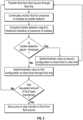
FIG. 1 is a schematic diagram of a system for generating a physiological fluid according to the present disclosure; andFIG. 2 is a method of operating the system ofFIG. 1 according to the present disclosure.- With reference to
FIG. 1 , asystem 10 for generating a physiological solution, such as peritoneal dialysis fluid is shown. The system includes afluid source 11, such as a water tank. Fluid is pumped fromfluid source 11 into afluid line 12 using apump 16 through abubble trap 14. Thepump 16 is disposed downstream of thefluid source 11 and may be any suitable pump for pumping fluid such as a gear pump, a piston pump, and the like. Thepump 16 may be disposed downstream or upstream of thebubble trap 14. Thebubble trap 14 may be any bifurcated chamber configured to separate air and water. Thebubble trap 14 may be coupled to anoptional venting valve 18 configured to vent air from thebubble trap 14. Thebubble trap 14 may also include anoptional pressure sensor 19 configured measure pressure within thebubble trap 14. The ventingvalve 18 and thepressure sensor 19 may be replaced by a mechanical vent. - The
system 10 also includes acontroller 20 coupled to the ventingvalve 18 and thepressure sensor 19. Thecontroller 20 is configured to receive pressure measurements from thepressure sensor 19 and to control the ventingvalve 18 based on the feedback from thepressure sensor 19. Thecontroller 20 may include any suitable processor (not shown) operably connected to a memory (not shown), which may include one or more of volatile, non-volatile, magnetic, optical, or electrical media, such as read-only memory (ROM), random access memory (RAM), electrically-erasable programmable ROM (EEPROM), non-volatile RAM (NVRAM), or flash memory. The processor may be any suitable processor (e.g., control circuit) adapted to perform the operations, calculations, and/or set of instructions described in the present disclosure including, but not limited to, a hardware processor, a field programmable gate array (FPGA), a digital signal processor (DSP), a central processing unit (CPU), a microprocessor, and combinations thereof. Those skilled in the art will appreciate that the processor may be substituted for by using any logic processor (e.g., control circuit) adapted to execute algorithms, calculations, and/or set of instructions described herein. In embodiments, the controller may include discrete electronic components, full analogic components, non-microcontroller or digital components. - The
controller 20 is coupled to thepump 16 and is configured to control the flow rate at which thepump 16 is operated. Thecontroller 20 is also coupled to other components of thesystem 10 and is configured to receive input from various sensors and control valves and other flow control devices. - The
system 10 further includes abubble detector 22 on thefluid line 12 disposed downstream of thebubble trap 14 and thepump 16. Thebubble detector 22 may be an acoustic and/or an optical bubble detector. Thebubble detector 22 is configured to detect the presence of air bubbles in the fluid based on disruption in the acoustic and/or optical signals transmitted through thefluid line 12. Thebubble detector 22 is coupled to thecontroller 20 and is configured to provide a measurement signal to thecontroller 20 indicating the presence of air bubbles in the fluid flowing thefluid line 12. - A
drain valve 24 is disposed downstream of thebubble detector 22 on thefluid line 12. In embodiments, thedrain valve 24 may be replaced by a plurality of electronic valves or any other suitable combination of flow control devices to avoid introducing air into thefluid line 12. Thedrain valve 24 may be a three-way solenoid valve controllable by thecontroller 20. Thedrain valve 24 is configured to operate in a first configuration, in which the fluid flows through thefluid line 12 and in a second configuration, in which the fluid flows to adrain line 26. - The
system 10 also includes a flowmeter 28, which may be an acoustic and/or an optical flowmeter, or any other meter susceptible to air bubbles present in the fluid, which would affect the accuracy of the flowmeter 28. The flowmeter 28 is coupled to thecontroller 20 and is configured to provide thecontroller 20 with a signal indicative of the flow rate through thefluid line 12. Thecontroller 20 is configured to control thepump 16 based on the measured flow rate to meter the fluid supplied from thefluid source 11. The fluid may be supplied downstream to be mixed with a dialysate concentrate supplied from aconcentrate source 30 to form dialysate. In embodiments, the fluid may be used to mix any other suitable physiological solution for use during dialysis, e.g., peritoneal dialysis or hemodialysis. - With reference to
FIG. 2 , a method for controlling thesystem 10 commences with a command supplied to thecontroller 20 for metering the fluid from thefluid source 11. This may be done in response to a treatment initialization command supplied to thecontroller 20 from a main controller (not shown). The command may include a total amount of fluid to be supplied from thefluid source 11. Thecontroller 20 calculates the flow rate for achieving the requested amount of fluid and sets thepump 16 to operate at the calculated flow rate. Once thepump 16 is activated, the fluid flow commences and the fluid flows through thebubble trap 14 and subsequently through thebubble detector 22. Thebubble detector 22 continuously monitors the fluid for bubbles, e.g., every 1 millisecond, and provides the signal to thecontroller 20. Thecontroller 20 compares the bubble detection signal from thebubble detector 22 to a threshold to determine if there are air bubbles present in the fluid. If thecontroller 20 detects that air bubbles are present based on the bubble detection signal exceeding the threshold, thecontroller 20 signals thedrain valve 24 to switch to the second configuration to allow the fluid to flow to thedrain line 26. Thedrain valve 24 is maintained in the second configuration until thecontroller 20 determines that the fluid no longer has any air bubbles. Thebubble detector 22 continues to transmit the bubble detection signal to thecontroller 20. If thecontroller 20 determines that the signal drops below the threshold indicating that there are no bubbles present in the fluid, thecontroller 20 signals thedrain valve 24 to switch into the first configuration, in which thedrain valve 24 allows the fluid to flow through thefluid line 12. Thecontroller 20 continues to operate thepump 16 until the requested amount of fluid has been metered by thepump 16, which is calculated by thecontroller 20 based on the flow rate signal supplied by the flowmeter 28.
Claims (2)
- A system (10) for metering fluid in a dialysis device comprising:a fluid source (11) storing a fluid;a fluid line (12) coupled to the fluid source and configured to pass the fluid therethrough;a controller (20);a flowmeter (28) coupled to the fluid line (12), the flowmeter configured to measure a flow rate of the fluid and provide a flow rate signal to the controller (20), wherein the flowmeter is at least one of an acoustic flowmeter or an optical flowmetera pump (16) coupled to the fluid line and configured move the fluid from the fluid source (11) through the fluid line (12), wherein the controller (20) is configured to meter the fluid by controlling the pump based on the flow rate signal,characterized in that the system further comprises:a valve (24) coupled to the fluid line (12) downstream of the fluid source (11) and upstream of the flowmeter (28), the valve configured to switch between a first configuration and a second configuration, wherein in the first configuration the valve directs the fluid through the fluid line (12) and in the second configuration the valve directs the fluid through a drain line (26); anda bubble detector (22) coupled to the fluid line (12) downstream of the fluid source (11) and upstream of the valve (24), the bubble detector configured to detect bubbles present in the fluid and to generate a bubble detection signal,wherein the controller (20) is coupled to the bubble detector (22) and the valve (24), the controller being further configured to:receive the bubble detection signal;switch the valve (24) to the first configuration in response to the bubble detection signal being below a threshold indicative of a presence of the bubbles in the fluid; andswitch the valve (24) to the second configuration in response to the bubble detection signal being above the threshold indicative of the presence of the bubbles in the fluid.
- A method of metering fluid in a dialysis device comprising a system (10) according to claim 1, the method comprising:pumping a fluid from the fluid source (11) to the fluid line (12) coupled to the fluid source;detecting bubbles present in the fluid at the bubble detector (22) coupled to the fluid line (12) downstream of the fluid source;transmitting the bubble detection signal from the bubble detector (22) to the controller (20);controlling the valve (24) coupled to the fluid line (12) downstream of the fluid source (11) to:switch the valve (24) to the first configuration, in which the valve directs the fluid through the fluid line, in response to the bubble detection signal being below the threshold indicative of a presence of the bubbles in the fluid; andswitch the valve (24) to the second configuration, in which the valve directs the fluid through the drain line (24), in response to the bubble detection signal being above the threshold indicative of the presence of the bubbles in the fluid;measuring a flow rate of the fluid at the flowmeter (28) coupled to the fluid line downstream of the valve (24);transmitting a flow rate signal from the flowmeter (28) to the controller (20); andwhen in the first configuration, pumping the fluid from the fluid source (11) through the metered fluid line via the pump (16) coupled to the fluid line (12), wherein the controller (20) meters the fluid by controlling the pump based on the flow rate signal.
Priority Applications (3)
| Application Number | Priority Date | Filing Date | Title |
|---|---|---|---|
| EP20203997.0AEP3991764B1 (en) | 2020-10-27 | 2020-10-27 | Flowmeter for proportioning water in dialysis system |
| CN202111218395.9ACN114487475A (en) | 2020-10-27 | 2021-10-20 | System for metering fluid in a dialysis device |
| US17/512,100US20220126009A1 (en) | 2020-10-27 | 2021-10-27 | Flowmeter for proportioning water in dialysis system |
Applications Claiming Priority (1)
| Application Number | Priority Date | Filing Date | Title |
|---|---|---|---|
| EP20203997.0AEP3991764B1 (en) | 2020-10-27 | 2020-10-27 | Flowmeter for proportioning water in dialysis system |
Publications (2)
| Publication Number | Publication Date |
|---|---|
| EP3991764A1 EP3991764A1 (en) | 2022-05-04 |
| EP3991764B1true EP3991764B1 (en) | 2024-03-06 |
Family
ID=73029866
Family Applications (1)
| Application Number | Title | Priority Date | Filing Date |
|---|---|---|---|
| EP20203997.0AActiveEP3991764B1 (en) | 2020-10-27 | 2020-10-27 | Flowmeter for proportioning water in dialysis system |
Country Status (3)
| Country | Link |
|---|---|
| US (1) | US20220126009A1 (en) |
| EP (1) | EP3991764B1 (en) |
| CN (1) | CN114487475A (en) |
Families Citing this family (1)
| Publication number | Priority date | Publication date | Assignee | Title |
|---|---|---|---|---|
| CN115826079B (en)* | 2022-11-07 | 2025-05-09 | 中国船舶集团有限公司第七一六研究所 | Portable artificial kidney system bubble detection and injection blockage judgment unit |
Family Cites Families (9)
| Publication number | Priority date | Publication date | Assignee | Title |
|---|---|---|---|---|
| US3946731A (en)* | 1971-01-20 | 1976-03-30 | Lichtenstein Eric Stefan | Apparatus for extracorporeal treatment of blood |
| EP0705611A2 (en)* | 1994-09-07 | 1996-04-10 | David S. Utterberg | Separable hemodialysis system |
| US20050209563A1 (en)* | 2004-03-19 | 2005-09-22 | Peter Hopping | Cassette-based dialysis medical fluid therapy systems, apparatuses and methods |
| US8449487B2 (en)* | 2006-12-01 | 2013-05-28 | Gambro Lundia Ab | Blood treatment apparatus |
| US20090114037A1 (en)* | 2007-10-11 | 2009-05-07 | Mark Forrest Smith | Photo-Acoustic Flow Meter |
| US8858787B2 (en)* | 2007-10-22 | 2014-10-14 | Baxter International Inc. | Dialysis system having non-invasive fluid velocity sensing |
| CN116370749A (en)* | 2012-05-24 | 2023-07-04 | 德卡产品有限公司 | Devices for infusion of fluids |
| US9526822B2 (en)* | 2013-02-01 | 2016-12-27 | Medtronic, Inc. | Sodium and buffer source cartridges for use in a modular controlled compliant flow path |
| JP7022927B2 (en)* | 2017-12-25 | 2022-02-21 | 澁谷工業株式会社 | Deaerator |
- 2020
- 2020-10-27EPEP20203997.0Apatent/EP3991764B1/enactiveActive
- 2021
- 2021-10-20CNCN202111218395.9Apatent/CN114487475A/enactivePending
- 2021-10-27USUS17/512,100patent/US20220126009A1/enactivePending
Also Published As
| Publication number | Publication date |
|---|---|
| EP3991764A1 (en) | 2022-05-04 |
| CN114487475A (en) | 2022-05-13 |
| US20220126009A1 (en) | 2022-04-28 |
Similar Documents
| Publication | Publication Date | Title |
|---|---|---|
| US11975131B2 (en) | Peritoneal dialysis systems, devices, and methods | |
| US12409259B2 (en) | Fluid preparation and treatment devices methods and systems | |
| JP6407856B2 (en) | Peritoneal dialysis system | |
| US9861733B2 (en) | Peritoneal dialysis systems, devices, and methods | |
| US6280634B1 (en) | Method of determining system volume of a dialysis machine | |
| US11517653B2 (en) | Hemodialysis system reservoir level sensor | |
| US10716883B2 (en) | Method and apparatus for intermittent pulsating proportioning of a dialysis fluid mixture | |
| US11504459B2 (en) | Dialysate concentration measurement sensor diagnosis | |
| EP3991764B1 (en) | Flowmeter for proportioning water in dialysis system | |
| US20230117917A1 (en) | Hemodialysis system reservoir level sensor | |
| WO2024129417A1 (en) | Systems and methods for using nitric oxide in dialysis |
Legal Events
| Date | Code | Title | Description |
|---|---|---|---|
| PUAI | Public reference made under article 153(3) epc to a published international application that has entered the european phase | Free format text:ORIGINAL CODE: 0009012 | |
| STAA | Information on the status of an ep patent application or granted ep patent | Free format text:STATUS: THE APPLICATION HAS BEEN PUBLISHED | |
| AK | Designated contracting states | Kind code of ref document:A1 Designated state(s):AL AT BE BG CH CY CZ DE DK EE ES FI FR GB GR HR HU IE IS IT LI LT LU LV MC MK MT NL NO PL PT RO RS SE SI SK SM TR | |
| STAA | Information on the status of an ep patent application or granted ep patent | Free format text:STATUS: REQUEST FOR EXAMINATION WAS MADE | |
| 17P | Request for examination filed | Effective date:20221024 | |
| RBV | Designated contracting states (corrected) | Designated state(s):AL AT BE BG CH CY CZ DE DK EE ES FI FR GB GR HR HU IE IS IT LI LT LU LV MC MK MT NL NO PL PT RO RS SE SI SK SM TR | |
| GRAP | Despatch of communication of intention to grant a patent | Free format text:ORIGINAL CODE: EPIDOSNIGR1 | |
| STAA | Information on the status of an ep patent application or granted ep patent | Free format text:STATUS: GRANT OF PATENT IS INTENDED | |
| INTG | Intention to grant announced | Effective date:20230928 | |
| RIN1 | Information on inventor provided before grant (corrected) | Inventor name:MARRA, ANTONIO GIUSEPPE | |
| GRAS | Grant fee paid | Free format text:ORIGINAL CODE: EPIDOSNIGR3 | |
| GRAA | (expected) grant | Free format text:ORIGINAL CODE: 0009210 | |
| STAA | Information on the status of an ep patent application or granted ep patent | Free format text:STATUS: THE PATENT HAS BEEN GRANTED | |
| AK | Designated contracting states | Kind code of ref document:B1 Designated state(s):AL AT BE BG CH CY CZ DE DK EE ES FI FR GB GR HR HU IE IS IT LI LT LU LV MC MK MT NL NO PL PT RO RS SE SI SK SM TR | |
| REG | Reference to a national code | Ref country code:CH Ref legal event code:EP | |
| REG | Reference to a national code | Ref country code:DE Ref legal event code:R096 Ref document number:602020026713 Country of ref document:DE | |
| REG | Reference to a national code | Ref country code:IE Ref legal event code:FG4D | |
| REG | Reference to a national code | Ref country code:LT Ref legal event code:MG9D | |
| PG25 | Lapsed in a contracting state [announced via postgrant information from national office to epo] | Ref country code:LT Free format text:LAPSE BECAUSE OF FAILURE TO SUBMIT A TRANSLATION OF THE DESCRIPTION OR TO PAY THE FEE WITHIN THE PRESCRIBED TIME-LIMIT Effective date:20240306 | |
| REG | Reference to a national code | Ref country code:NL Ref legal event code:MP Effective date:20240306 | |
| PG25 | Lapsed in a contracting state [announced via postgrant information from national office to epo] | Ref country code:GR Free format text:LAPSE BECAUSE OF FAILURE TO SUBMIT A TRANSLATION OF THE DESCRIPTION OR TO PAY THE FEE WITHIN THE PRESCRIBED TIME-LIMIT Effective date:20240607 | |
| PG25 | Lapsed in a contracting state [announced via postgrant information from national office to epo] | Ref country code:RS Free format text:LAPSE BECAUSE OF FAILURE TO SUBMIT A TRANSLATION OF THE DESCRIPTION OR TO PAY THE FEE WITHIN THE PRESCRIBED TIME-LIMIT Effective date:20240606 Ref country code:HR Free format text:LAPSE BECAUSE OF FAILURE TO SUBMIT A TRANSLATION OF THE DESCRIPTION OR TO PAY THE FEE WITHIN THE PRESCRIBED TIME-LIMIT Effective date:20240306 | |
| PG25 | Lapsed in a contracting state [announced via postgrant information from national office to epo] | Ref country code:ES Free format text:LAPSE BECAUSE OF FAILURE TO SUBMIT A TRANSLATION OF THE DESCRIPTION OR TO PAY THE FEE WITHIN THE PRESCRIBED TIME-LIMIT Effective date:20240306 | |
| PG25 | Lapsed in a contracting state [announced via postgrant information from national office to epo] | Ref country code:RS Free format text:LAPSE BECAUSE OF FAILURE TO SUBMIT A TRANSLATION OF THE DESCRIPTION OR TO PAY THE FEE WITHIN THE PRESCRIBED TIME-LIMIT Effective date:20240606 Ref country code:NO Free format text:LAPSE BECAUSE OF FAILURE TO SUBMIT A TRANSLATION OF THE DESCRIPTION OR TO PAY THE FEE WITHIN THE PRESCRIBED TIME-LIMIT Effective date:20240606 Ref country code:LT Free format text:LAPSE BECAUSE OF FAILURE TO SUBMIT A TRANSLATION OF THE DESCRIPTION OR TO PAY THE FEE WITHIN THE PRESCRIBED TIME-LIMIT Effective date:20240306 Ref country code:HR Free format text:LAPSE BECAUSE OF FAILURE TO SUBMIT A TRANSLATION OF THE DESCRIPTION OR TO PAY THE FEE WITHIN THE PRESCRIBED TIME-LIMIT Effective date:20240306 Ref country code:GR Free format text:LAPSE BECAUSE OF FAILURE TO SUBMIT A TRANSLATION OF THE DESCRIPTION OR TO PAY THE FEE WITHIN THE PRESCRIBED TIME-LIMIT Effective date:20240607 Ref country code:FI Free format text:LAPSE BECAUSE OF FAILURE TO SUBMIT A TRANSLATION OF THE DESCRIPTION OR TO PAY THE FEE WITHIN THE PRESCRIBED TIME-LIMIT Effective date:20240306 Ref country code:ES Free format text:LAPSE BECAUSE OF FAILURE TO SUBMIT A TRANSLATION OF THE DESCRIPTION OR TO PAY THE FEE WITHIN THE PRESCRIBED TIME-LIMIT Effective date:20240306 Ref country code:BG Free format text:LAPSE BECAUSE OF FAILURE TO SUBMIT A TRANSLATION OF THE DESCRIPTION OR TO PAY THE FEE WITHIN THE PRESCRIBED TIME-LIMIT Effective date:20240306 | |
| REG | Reference to a national code | Ref country code:AT Ref legal event code:MK05 Ref document number:1662858 Country of ref document:AT Kind code of ref document:T Effective date:20240306 | |
| PG25 | Lapsed in a contracting state [announced via postgrant information from national office to epo] | Ref country code:SE Free format text:LAPSE BECAUSE OF FAILURE TO SUBMIT A TRANSLATION OF THE DESCRIPTION OR TO PAY THE FEE WITHIN THE PRESCRIBED TIME-LIMIT Effective date:20240306 Ref country code:LV Free format text:LAPSE BECAUSE OF FAILURE TO SUBMIT A TRANSLATION OF THE DESCRIPTION OR TO PAY THE FEE WITHIN THE PRESCRIBED TIME-LIMIT Effective date:20240306 | |
| PG25 | Lapsed in a contracting state [announced via postgrant information from national office to epo] | Ref country code:NL Free format text:LAPSE BECAUSE OF FAILURE TO SUBMIT A TRANSLATION OF THE DESCRIPTION OR TO PAY THE FEE WITHIN THE PRESCRIBED TIME-LIMIT Effective date:20240306 | |
| PG25 | Lapsed in a contracting state [announced via postgrant information from national office to epo] | Ref country code:NL Free format text:LAPSE BECAUSE OF FAILURE TO SUBMIT A TRANSLATION OF THE DESCRIPTION OR TO PAY THE FEE WITHIN THE PRESCRIBED TIME-LIMIT Effective date:20240306 | |
| PG25 | Lapsed in a contracting state [announced via postgrant information from national office to epo] | Ref country code:IS Free format text:LAPSE BECAUSE OF FAILURE TO SUBMIT A TRANSLATION OF THE DESCRIPTION OR TO PAY THE FEE WITHIN THE PRESCRIBED TIME-LIMIT Effective date:20240706 | |
| PG25 | Lapsed in a contracting state [announced via postgrant information from national office to epo] | Ref country code:SM Free format text:LAPSE BECAUSE OF FAILURE TO SUBMIT A TRANSLATION OF THE DESCRIPTION OR TO PAY THE FEE WITHIN THE PRESCRIBED TIME-LIMIT Effective date:20240306 Ref country code:PT Free format text:LAPSE BECAUSE OF FAILURE TO SUBMIT A TRANSLATION OF THE DESCRIPTION OR TO PAY THE FEE WITHIN THE PRESCRIBED TIME-LIMIT Effective date:20240708 | |
| PG25 | Lapsed in a contracting state [announced via postgrant information from national office to epo] | Ref country code:CZ Free format text:LAPSE BECAUSE OF FAILURE TO SUBMIT A TRANSLATION OF THE DESCRIPTION OR TO PAY THE FEE WITHIN THE PRESCRIBED TIME-LIMIT Effective date:20240306 Ref country code:EE Free format text:LAPSE BECAUSE OF FAILURE TO SUBMIT A TRANSLATION OF THE DESCRIPTION OR TO PAY THE FEE WITHIN THE PRESCRIBED TIME-LIMIT Effective date:20240306 | |
| PG25 | Lapsed in a contracting state [announced via postgrant information from national office to epo] | Ref country code:AT Free format text:LAPSE BECAUSE OF FAILURE TO SUBMIT A TRANSLATION OF THE DESCRIPTION OR TO PAY THE FEE WITHIN THE PRESCRIBED TIME-LIMIT Effective date:20240306 | |
| PG25 | Lapsed in a contracting state [announced via postgrant information from national office to epo] | Ref country code:PL Free format text:LAPSE BECAUSE OF FAILURE TO SUBMIT A TRANSLATION OF THE DESCRIPTION OR TO PAY THE FEE WITHIN THE PRESCRIBED TIME-LIMIT Effective date:20240306 | |
| PG25 | Lapsed in a contracting state [announced via postgrant information from national office to epo] | Ref country code:SK Free format text:LAPSE BECAUSE OF FAILURE TO SUBMIT A TRANSLATION OF THE DESCRIPTION OR TO PAY THE FEE WITHIN THE PRESCRIBED TIME-LIMIT Effective date:20240306 | |
| PG25 | Lapsed in a contracting state [announced via postgrant information from national office to epo] | Ref country code:SM Free format text:LAPSE BECAUSE OF FAILURE TO SUBMIT A TRANSLATION OF THE DESCRIPTION OR TO PAY THE FEE WITHIN THE PRESCRIBED TIME-LIMIT Effective date:20240306 Ref country code:SK Free format text:LAPSE BECAUSE OF FAILURE TO SUBMIT A TRANSLATION OF THE DESCRIPTION OR TO PAY THE FEE WITHIN THE PRESCRIBED TIME-LIMIT Effective date:20240306 Ref country code:RO Free format text:LAPSE BECAUSE OF FAILURE TO SUBMIT A TRANSLATION OF THE DESCRIPTION OR TO PAY THE FEE WITHIN THE PRESCRIBED TIME-LIMIT Effective date:20240306 Ref country code:PT Free format text:LAPSE BECAUSE OF FAILURE TO SUBMIT A TRANSLATION OF THE DESCRIPTION OR TO PAY THE FEE WITHIN THE PRESCRIBED TIME-LIMIT Effective date:20240708 Ref country code:PL Free format text:LAPSE BECAUSE OF FAILURE TO SUBMIT A TRANSLATION OF THE DESCRIPTION OR TO PAY THE FEE WITHIN THE PRESCRIBED TIME-LIMIT Effective date:20240306 Ref country code:IS Free format text:LAPSE BECAUSE OF FAILURE TO SUBMIT A TRANSLATION OF THE DESCRIPTION OR TO PAY THE FEE WITHIN THE PRESCRIBED TIME-LIMIT Effective date:20240706 Ref country code:EE Free format text:LAPSE BECAUSE OF FAILURE TO SUBMIT A TRANSLATION OF THE DESCRIPTION OR TO PAY THE FEE WITHIN THE PRESCRIBED TIME-LIMIT Effective date:20240306 Ref country code:CZ Free format text:LAPSE BECAUSE OF FAILURE TO SUBMIT A TRANSLATION OF THE DESCRIPTION OR TO PAY THE FEE WITHIN THE PRESCRIBED TIME-LIMIT Effective date:20240306 Ref country code:AT Free format text:LAPSE BECAUSE OF FAILURE TO SUBMIT A TRANSLATION OF THE DESCRIPTION OR TO PAY THE FEE WITHIN THE PRESCRIBED TIME-LIMIT Effective date:20240306 | |
| PG25 | Lapsed in a contracting state [announced via postgrant information from national office to epo] | Ref country code:IT Free format text:LAPSE BECAUSE OF FAILURE TO SUBMIT A TRANSLATION OF THE DESCRIPTION OR TO PAY THE FEE WITHIN THE PRESCRIBED TIME-LIMIT Effective date:20240306 | |
| REG | Reference to a national code | Ref country code:DE Ref legal event code:R097 Ref document number:602020026713 Country of ref document:DE | |
| PG25 | Lapsed in a contracting state [announced via postgrant information from national office to epo] | Ref country code:IT Free format text:LAPSE BECAUSE OF FAILURE TO SUBMIT A TRANSLATION OF THE DESCRIPTION OR TO PAY THE FEE WITHIN THE PRESCRIBED TIME-LIMIT Effective date:20240306 | |
| PLBE | No opposition filed within time limit | Free format text:ORIGINAL CODE: 0009261 | |
| STAA | Information on the status of an ep patent application or granted ep patent | Free format text:STATUS: NO OPPOSITION FILED WITHIN TIME LIMIT | |
| PG25 | Lapsed in a contracting state [announced via postgrant information from national office to epo] | Ref country code:DK Free format text:LAPSE BECAUSE OF FAILURE TO SUBMIT A TRANSLATION OF THE DESCRIPTION OR TO PAY THE FEE WITHIN THE PRESCRIBED TIME-LIMIT Effective date:20240306 | |
| PG25 | Lapsed in a contracting state [announced via postgrant information from national office to epo] | Ref country code:DK Free format text:LAPSE BECAUSE OF FAILURE TO SUBMIT A TRANSLATION OF THE DESCRIPTION OR TO PAY THE FEE WITHIN THE PRESCRIBED TIME-LIMIT Effective date:20240306 | |
| 26N | No opposition filed | Effective date:20241209 | |
| PG25 | Lapsed in a contracting state [announced via postgrant information from national office to epo] | Ref country code:SI Free format text:LAPSE BECAUSE OF FAILURE TO SUBMIT A TRANSLATION OF THE DESCRIPTION OR TO PAY THE FEE WITHIN THE PRESCRIBED TIME-LIMIT Effective date:20240306 | |
| REG | Reference to a national code | Ref country code:DE Ref legal event code:R119 Ref document number:602020026713 Country of ref document:DE | |
| REG | Reference to a national code | Ref country code:CH Ref legal event code:PL | |
| GBPC | Gb: european patent ceased through non-payment of renewal fee | Effective date:20241027 | |
| PG25 | Lapsed in a contracting state [announced via postgrant information from national office to epo] | Ref country code:MC Free format text:LAPSE BECAUSE OF FAILURE TO SUBMIT A TRANSLATION OF THE DESCRIPTION OR TO PAY THE FEE WITHIN THE PRESCRIBED TIME-LIMIT Effective date:20240306 | |
| PG25 | Lapsed in a contracting state [announced via postgrant information from national office to epo] | Ref country code:DE Free format text:LAPSE BECAUSE OF NON-PAYMENT OF DUE FEES Effective date:20250501 | |
| PG25 | Lapsed in a contracting state [announced via postgrant information from national office to epo] | Ref country code:GB Free format text:LAPSE BECAUSE OF NON-PAYMENT OF DUE FEES Effective date:20241027 | |
| PG25 | Lapsed in a contracting state [announced via postgrant information from national office to epo] | Ref country code:LU Free format text:LAPSE BECAUSE OF NON-PAYMENT OF DUE FEES Effective date:20241027 Ref country code:BE Free format text:LAPSE BECAUSE OF NON-PAYMENT OF DUE FEES Effective date:20241031 | |
| PG25 | Lapsed in a contracting state [announced via postgrant information from national office to epo] | Ref country code:FR Free format text:LAPSE BECAUSE OF NON-PAYMENT OF DUE FEES Effective date:20241031 | |
| PG25 | Lapsed in a contracting state [announced via postgrant information from national office to epo] | Ref country code:CH Free format text:LAPSE BECAUSE OF NON-PAYMENT OF DUE FEES Effective date:20241031 | |
| REG | Reference to a national code | Ref country code:BE Ref legal event code:MM Effective date:20241031 |