EP3989651B1 - Reporting power headroom for aggregated carriers - Google Patents
Reporting power headroom for aggregated carriersDownload PDFInfo
- Publication number
- EP3989651B1 EP3989651B1EP21215914.9AEP21215914AEP3989651B1EP 3989651 B1EP3989651 B1EP 3989651B1EP 21215914 AEP21215914 AEP 21215914AEP 3989651 B1EP3989651 B1EP 3989651B1
- Authority
- EP
- European Patent Office
- Prior art keywords
- power headroom
- carriers
- carrier
- related information
- access node
- Prior art date
- Legal status (The legal status is an assumption and is not a legal conclusion. Google has not performed a legal analysis and makes no representation as to the accuracy of the status listed.)
- Active
Links
Images


Classifications
- H—ELECTRICITY
- H04—ELECTRIC COMMUNICATION TECHNIQUE
- H04W—WIRELESS COMMUNICATION NETWORKS
- H04W52/00—Power management, e.g. Transmission Power Control [TPC] or power classes
- H04W52/04—Transmission power control [TPC]
- H04W52/30—Transmission power control [TPC] using constraints in the total amount of available transmission power
- H04W52/36—Transmission power control [TPC] using constraints in the total amount of available transmission power with a discrete range or set of values, e.g. step size, ramping or offsets
- H04W52/365—Power headroom reporting
- H—ELECTRICITY
- H04—ELECTRIC COMMUNICATION TECHNIQUE
- H04L—TRANSMISSION OF DIGITAL INFORMATION, e.g. TELEGRAPHIC COMMUNICATION
- H04L5/00—Arrangements affording multiple use of the transmission path
- H04L5/003—Arrangements for allocating sub-channels of the transmission path
- H04L5/0053—Allocation of signalling, i.e. of overhead other than pilot signals
- H—ELECTRICITY
- H04—ELECTRIC COMMUNICATION TECHNIQUE
- H04W—WIRELESS COMMUNICATION NETWORKS
- H04W52/00—Power management, e.g. Transmission Power Control [TPC] or power classes
- H04W52/04—Transmission power control [TPC]
- H04W52/18—TPC being performed according to specific parameters
- H04W52/24—TPC being performed according to specific parameters using SIR [Signal to Interference Ratio] or other wireless path parameters
- H04W52/242—TPC being performed according to specific parameters using SIR [Signal to Interference Ratio] or other wireless path parameters taking into account path loss
- H—ELECTRICITY
- H04—ELECTRIC COMMUNICATION TECHNIQUE
- H04W—WIRELESS COMMUNICATION NETWORKS
- H04W52/00—Power management, e.g. Transmission Power Control [TPC] or power classes
- H04W52/04—Transmission power control [TPC]
- H04W52/30—Transmission power control [TPC] using constraints in the total amount of available transmission power
- H04W52/34—TPC management, i.e. sharing limited amount of power among users or channels or data types, e.g. cell loading
- H—ELECTRICITY
- H04—ELECTRIC COMMUNICATION TECHNIQUE
- H04W—WIRELESS COMMUNICATION NETWORKS
- H04W72/00—Local resource management
- H04W72/20—Control channels or signalling for resource management
- H—ELECTRICITY
- H04—ELECTRIC COMMUNICATION TECHNIQUE
- H04W—WIRELESS COMMUNICATION NETWORKS
- H04W72/00—Local resource management
- H04W72/20—Control channels or signalling for resource management
- H04W72/21—Control channels or signalling for resource management in the uplink direction of a wireless link, i.e. towards the network
- H—ELECTRICITY
- H04—ELECTRIC COMMUNICATION TECHNIQUE
- H04W—WIRELESS COMMUNICATION NETWORKS
- H04W76/00—Connection management
- H04W76/10—Connection setup
Definitions
- the terms “user agent” and “UA”might in some cases refer to mobile devices such as mobile telephones, personal digital assistants, handheld or laptop computers, and similar devices that have telecommunications capabilities. Such a UA might consist of a device and its associated removable memory module, such as but not limited to a Universal Integrated Circuit Card (UICC) that includes a Subscriber Identity Module (SIM) application, a Universal Subscriber Identity Module (USIM) application, or a Removable User Identity Module (R-UIM) application. Alternatively, such a UA might consist of the device itself without such a module. In other cases, the term “UA” might refer to devices that have similar capabilities but that are not transportable, such as desktop computers, set-top boxes, or network appliances. The term “UA” can also refer to any hardware or software component that can terminate a communication session for a user. Also, the terms “user agent,” “UA,” “user equipment,” “UE,” “user device” and “user node” might be used synonymously herein.
- UICCUniversal Integrated Circuit Card
- LTELong-term evolution
- an LTE systemmight include an Evolved Universal Terrestrial Radio Access Network (E-UTRAN) node B (eNB), a wireless access point, or a similar component rather than a traditional base station.
- E-UTRANEvolved Universal Terrestrial Radio Access Network
- eNBEvolved Universal Terrestrial Radio Access Network node B
- wireless access pointa wireless access point, or a similar component rather than a traditional base station.
- the term "access node”will refer to any component of a wireless telecommunications system, such as a traditional base station, a wireless access point, or an LTE eNB, that creates a geographical area of reception and transmission coverage allowing a UA to access other components in the system.
- An access nodemay comprise a plurality of hardware and software.
- LTEwas standardized in Release 8 of the wireless telecommunications standards promoted by the 3rd Generation Partnership Project (3GPP). 3GPP Release 10 standards deal with LTE-Advanced or LTE-A technology. Under LTE-A, relays and other advanced components might be included in a wireless telecommunications network.
- a relayis a component in a wireless network that is configured to extend or enhance the coverage created by an access node or another relay.
- access nodes and relaysmay be distinct components with different capabilities and functions, for ease of reference, the term "access node" will be used herein to refer to either a relay or an access node as described above.
- the signals that carry data between UAs, relay nodes, and access nodescan have frequency, time, and coding parameters and other characteristics that might be specified by a network node.
- a connection between any of these elements that has a specific set of such characteristicscan be referred to as a resource.
- the terms "resource,” “communications connection,” “channel,” and “communications link”might be used synonymously herein.
- a network nodetypically establishes a different resource for each UA or other network node with which it is communicating at any particular time.
- WO2006/019441discloses a multicarrier CDMA system, whereby a packet stream is divided into one or more substreams depending on a selected number of carrier frequencies, and each substream is transmitted on a corresponding carrier frequency.
- the number of carrier frequenciesis selectively varied during transmission of the packet data.
- PUSCH Power Control for LTE-Advancedby Nokia Siemens Networks, 3GPP TSG RAN WG1 #56 Meeting , discloses the possibility to extend the principles of Rel' 8 uplink power control to LTE-Advanced.
- UL Transmission Power Control in LTE-Aby Samsung, 3GPP TSG RAN WG1 #56bis , discloses an overview for the application of transmission power control (TPC) for the PUSCH, the PUCCH, and the SRS in LIB-Advanced (LTE-A).
- DC-HSUPA impact on RAN2 specificationsby Qualcomm Europe, 3GPP TSG RAN WG2 #65bis , discloses the MAC, RLC and RRC areas with potential impact from the introduction of dual carrier operation on the uplink, after evaluating gains from any potential changes.
- 3rd Generation Partnership Project; Technical Specification Group Radio Access Network; Medium Access Control (MAC) protocol specification3GPP TS 25.321, V7.5.0 , specifies the MAC protocol.
- Remaining issues on Uplink Power Control for Carrier Aggregationby Research In Motion UK Limited, 3GPP TSG RAN WG1 Meeting #59bis , discloses some issues to design detailed power control operation for LTE-A supporting carrier aggregation.
- carrier aggregationmight be used in order to support wider transmission bandwidths and hence increase the potential peak data rate to meet LTE-A requirements.
- carrier aggregationmultiple component carriers are aggregated and can be allocated in a subframe to a UA as shown in Figure 1 .
- each component carrier 110has a width of 20 MHz and the total system bandwidth becomes 100 MHz.
- the UAmay receive or transmit on a multiple of up to five component carriers depending on its capabilities.
- carrier aggregationmay occur with carriers located in the same band and/or carriers located in different bands. For example, one carrier may be located at 2 GHz and a second aggregated carrier may be located at 800 MHz.
- a UAtransmits a power headroom report (PHR) and a buffer status report (BSR) to an access node in order to assist with uplink scheduling.
- the access nodeuses this information when it determines the amount of frequency resources and proper modulation and coding scheme (MCS) level for physical uplink shared channel (PUSCH) transmissions.
- FIG 2shows the general flow of an uplink transmission from a UA 210 to an access node 220.
- the UA 210transmits a scheduling request on the physical uplink control channel (PUCCH) if there is no uplink PUSCH resource available for the initial transmission.
- PUCCHphysical uplink control channel
- the access node 220Since the access node 220 does not know the current uplink channel conditions or the amount of pending data, the access node 220 schedules a small amount of uplink resources, as shown at event 232. The UA 210, at event 233, then transmits a PHR and BSR using this initial uplink resource. With this additional information, the access node 220, at event 234, can provide the UA 210 with a larger amount of uplink resources. At event 235, the UA 210 transmits to the access node 220 at a higher data rate according to the UA buffer status and the observed channel conditions.
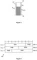
- the power headroom (PH) 310is defined as the difference between the nominal UA maximum transmit power (P cmax ) 320 and the estimated power for PUSCH transmissions (P pusch(i) ) 330.
- P cmaxthe nominal UA maximum transmit power
- P pusch(i)the estimated power for PUSCH transmissions
- the PH valuescan be different depending on the current UA channel conditions. From the access node scheduler's point of view, a large PH means that the UA has more room to increase its power to accommodate a higher data rate transmission, while a small PH means that the UA cannot increase its data rate.
- This equationmeans that the PH is the remaining available transmission power, obtained by subtracting the uplink transmission power at the ith subframe from the maximum allowable transmission power.
- the parametersare defined as follows.
- UAsIn LTE-A systems, UAs might report their PH to an access node to assist with uplink scheduling as in the case with LTE systems.
- the PH reporting approach used in LTEwhere PH is the difference between the maximum allowable and current uplink transmission powers, may not be appropriate in LTE-A.
- An LTE-A UAis able to transmit using multiple carriers simultaneously, and scheduling might be performed on a per-carrier basis with different MCS levels. If each carrier is constrained to use the same uplink transmit power, one PH report may be sufficient. However, the uplink transmit power would be expected to be different for each carrier because some power-related parameters might vary for different carriers.
- the path losscan be different if the carriers are located in different bands. Assuming two example carriers are located at 2 GHz and 800 MHz, respectively, the expected statistical difference in path loss can be calculated as a function of the frequency based on the path loss model in 3GPP Technical Report (TR) 25.942.
- the path loss Lis given as 40(1 - 4 ⁇ 10 -3 Dhb) Log 10 (R) - 18Log 10 (Dhb) + 21 Log 10 (f) + 80 dB, where f is the frequency in MHz, Dhb is the access node antenna height in meters (in 3GPP, 15m is assumed), and R is the distance between the access node and the UA in kilometers.
- the power control adjustment, f(i)might be different for different carriers.
- An access nodecould transmit individual TPC (Transmit Power Control) commands per carrier or a single combined TPC command for all of the carriers. Even though the access node originates the TPC commands, it would be difficult for the access node to correctly track the current f(i) values per carrier due to possible TPC signaling errors and/or TPC signals that were mis-detected by the UA.
- TPCTransmit Power Control
- P O_PUSCHmight vary for different carriers.
- P O_PUSCHis a cell- and UA-specific parameter that adjusts the target signal to interference-plus-noise ratio (SINR) based on the interference level. Since each component carrier is scheduled independently, each carrier might experience a different inter-cell interference level. The loading of different carriers may be different depending on the scheduling in the neighbor cells. For example, the access node might schedule cell-edge UAs on one carrier and more centrally-located UAs on the remaining carriers.
- the network topologymay result in different neighboring cells having different carriers available. For instance, one cell may have five carriers in total, but a neighboring cell that is expected to be less lightly loaded may only be configured with a maximum of three carriers.
- ⁇ (j)might be different for different carriers.
- ⁇ (j)is a cell-specific parameter intended to improve cell throughput under small interference levels. This parameter can be varied based on the cell loading and/or on the UA distribution within a cell.
- the uplink transmit power, and therefore the power headroom,might be different for each carrier in a set of aggregated carriers.
- the PH of all carrierscould be reported to the access node.
- thiscould result in excessive signaling overhead, since it may not be necessary to report the PH for every carrier.
- various schemesare provided for efficiently transmitting per-carrier PH values for a set of aggregated carriers in order to reduce signaling overhead.
- a PH valueMost of the factors determining a PH value are carrier-specific but, other than path loss (and possibly the current power control correction), the access node is typically aware of these parameters. Therefore, if the access node is made aware of the path loss for each carrier, the access node can calculate a PH for each carrier.
- a UAcould report an observed path loss in a higher-layer measurement report, but such a report may not be sent frequently enough because higher-layer messages tend to be larger and generally incur some delay before being triggered. Consequently, it may be advantageous for the UA to report a separate PH value to the access node for each carrier. However, it may be unnecessary to report separate PH values for all carriers given that the path losses of carriers located in the same frequency band are typically similar.
- the number of carriers for which the PH or PH-related information is reportedis less than or equal to the total number of configured carriers.
- a carrier for which a PH or PH-related information is reportedis referred to herein as a "reporting carrier".
- an access nodeconfigures the carrier set to be reported.
- the access nodeselects the carriers for which PH reporting will be performed and communicates this decision to the UA via radio resource control (RRC) signaling or media access control (MAC) control elements.
- RRCradio resource control
- MACmedia access control
- This approachprovides additional freedom to the access node because the access node can select the reporting carriers regardless of whether those carriers are located in the same or different bands.
- the access nodeuses a bitmap to indicate which carriers' PHs should be reported.
- a PH reportmight be transmitted at periodic intervals and/or when a triggering event occurs.
- a PH reportis triggered if any of the following events occur: the prohibitPHR-Timer expires or has expired and the path loss has changed more than dl-PathlossChange dB since the last power headroom report, when the UA has uplink resources for a new transmission; the periodicPHR-Timer expires, in which case the PHR is referred to as a "Periodic PHR"; upon configuration and reconfiguration of a Periodic PHR.
- these criteriaare expanded to support carrier aggregation under LTE-A.
- the triggers related to the expiration of the periodicPHR-Timer and the configuration and reconfiguration of a Periodic PHRmight remain the same, but the trigger related to the expiration of the prohibitPHR-Timer might be modified.
- a PH reportis triggered if the prohibitPHR-Timer expires or has expired and the path loss of any reporting carrier has changed more than dl-PathlossChange dB since the last power headroom report, when the UA has uplink resources for a new transmission.
- the PH reporting schemecould be such that only reporting carriers that satisfy this dl-PathlossChange criterion actually report their new PH values. That is, not all configured reporting carriers would actually include their PH values in the PH report.
- a PH reportis triggered when a UA receives a new carrier configuration from the access node and/or a new PH reporting configuration that includes a new reporting carrier.
- a UAcould transmit a PH report to an access node via RRC signaling or via MAC control elements. Since the RRC signaling approach might incur additional delay and signaling overhead, the MAC control element approach may be preferable.
- the following alternatives for transmitting a PH or PH-related informationare based on the MAC control element approach. If there is no explicit indication otherwise, the PH reporting discussed in the following alternatives is triggered according to the criteria described above.
- a UAwhen PH reporting is triggered, transmits the PHs for all of the reporting carriers. For example, if there are four reporting carriers, when the observed path loss difference for one of the reporting carriers exceeds the configured threshold (that is, the path loss of a reporting carrier has changed more than dl-PathlossChange dB), the UA transmits the PHs for all four of the reporting carriers.
- FIG. 4illustrates an example of a MAC control element 400 that could be used for transmitting the PHs of all reporting carriers.
- the control element 400consists of three byte-aligned octets 410.
- the number of PH valuesequals the number of reporting carriers. In this example four reporting carriers have been configured.
- the length of the PH valuesis six bits, as in LTE.
- Each PH krepresents the PH of carrier k.
- the UAcan decide not to transmit all PHs or transmit PHs of a subset of carriers in the MAC control element to be accommodated in the allocated UL resources.
- the UAcan select carriers based on the logical or physical carrier indexing. In one embodiment, the UA can select a carrier based on the priority of the carrier. For example, the UA can transmit the PH of the uplink anchor carrier or a carrier used to transmit data with a high quality of service (QoS).
- QoSquality of service
- a UAtransmits the PH of only a certain reporting carrier or of only certain reporting carriers.
- the UAtransmits PH information only for a carrier or carriers for which a specific event trigger occurs or when that carrier's PUSCH is scheduled.
- Different dl-PathlossChange, periodicPHR-Timer, and / or prohibitPHR-Timercan be configured for each carrier or for a subset of carriers.
- PHs of all triggered carrierscan be transmitted. For example, when the path loss difference is larger than a preconfigured threshold in carrier #1, UA would transmit the PH only for carrier #1. To indicate to the access node which reporting carriers' PHs are being transmitted, a bitmap is included with a PH report.
- the UAcan decide not to transmit all PHs or transmit PHs of a subset of carriers in the MAC control element to be accommodated in the allocated UL resources.
- the UAcan select carriers based on the logical or physical carrier indexing. In one embodiment, the UA can select a carrier based on the priority of carrier. For example, the UA can transmit PH of the uplink anchor carrier or carrier transmitting the high QoS data.
- a MAC control element 900includes a bitmap 910 with a length equal to the number of reporting carriers. In this case, there are five reporting carriers, so the bitmap 910 includes five bits.
- the bit in the k th positionindicates whether or not the PH value of the k th carrier is included in the control element 900. For example, "1" may mean that the corresponding PH value is included, while “0” may mean that the PH value is not included.
- the first, fourth, and fifth bits of the bitmap 910are set to "1", so PH values for the first, fourth, and fifth carriers are included in the control element 900.
- a UAmight report PH values for all carriers periodically. Meanwhile, in the event-triggered case, the UA reports only for the selected carriers in order to reduce the signaling overhead.
- the calculation used to obtain PH in an LTE-based environmentis modified to be carrier-specific in an L TE-A-based environment.
- An example of such a modified PH equation for calculating the PH value for LTE-Ais given below.
- PH k iP CMAX , k ⁇ 10 log 10 M PUSCH , k i + P O _ PUSCH , k j + ⁇ k j ⁇ PL k + ⁇ TF , k i + ⁇ k i
- the definition of each parameteris given in 3GPP TS 36.213, but parameter values are different on a per-carrier basis.
- kdenotes the kth carrier to be reported.
- a UAmay not have a current PUSCH allocation for a particular reporting carrier. Such a UA would not have the necessary scheduling information and therefore could not perform the PH calculation.
- the UAmakes certain assumptions in this situation in order to calculate and report PH values for any non-scheduled carriers. One of three different techniques might be used.
- the UAcopies the resource configuration for a scheduled carrier. At least one carrier must be scheduled in order for the UA to be able to transmit a PH report. Any non-scheduled reporting carriers can use the same scheduling configuration (i.e., the number of resource blocks and the transport block size), as given for a selected scheduled carrier, in order to calculate a PH value. Possible methods for selecting a scheduled carrier whose scheduling configuration would be "copied" could be to select the nearest carrier as measured by carrier frequency or to select the scheduled carrier with the lowest or highest carrier frequency.
- the configuration of the Sounding Reference Signal (SRS) transmissionis used.
- the SRSis transmitted periodically from the UA and is used by the access node to detect the UA channel situation.
- the access nodeconfigures the UA to transmit SRS in each carrier.
- the number of resource blocks of the SRS transmissionis semi-statically configured and ⁇ TF,k ( i ) is set to zero, so the UA is typically aware of these values. Since both the UA and access node know the SRS transmission parameters, the number of resource blocks of the SRS transmission can be used if a PUSCH transmission is not scheduled for a particular carrier.
- a reference configurationis predefined.
- Fixed reference values for the number of resource blocks and the transport block sizecan be predefined or configured by higher-layer signaling and then used in the calculation of a PH value for a non-scheduled carrier.
- the PUCCH-related PHmay need to be transmitted to indicate that the transmit power used for the PUCCH-related PH can be the PH only for the PUCCH or can be a combined PUCCH and PUSCH PH. If the access node receives only the PUSCH PH, it may be difficult to exactly estimate the allowable PUSCH power when the PUSCH and PUCCH are transmitted simultaneously, because the sum of PUSCH and PUCCH power is limited not to exceed the maximum transmit power.
- the UAtransmits the PUCCH-related PH in a MAC control element when PH reporting is triggered and a PUSCH resource is scheduled.
- the PUCCH-related PHis calculated by the UA based on the actual transmit power of the PUCCH.
- the calculated PUCCH-related PHis inserted in the MAC control element and transmitted to the access node.
- the UAcannot calculate the PH because the PUCCH transmit power is not defined when the PUCCH is not transmitted.
- One solutionis to assume a reference configuration among different PUCCH formats when the UA transmits the PUCCH-related PH and the PUCCH is not transmitted.
- This reference configurationcan be predefined in the specification or configured by higher layer signaling.
- the higher layer signalingcould be UA-specific signaling or broadcast signaling.
- the reference configurationcould be one of the PUCCH formats from 3rd Generation Partnership Project (3GPP) Technical Specification (TS) 36.211.
- the reference configurationcould be PUCCH format 1 A from TS 36.211.
- the PUCCH format requiring the most transmission poweris used as the reference configuration.
- the UAestimates the transmission power needed to transmit the PUCCH assuming it were to transmit the PUCCH using the reference configuration. It then uses this estimated transmission power to calculate the PUCCH-related PH.
- PH i( P CMAX ⁇ ⁇ P 0 _ PUCCH + PL + h n CQI n HARQ + ⁇ F _ PUCCH F + g i if PUCCHis transmitted P CMAX ⁇ P 0 _ PUCCH + PL + g i otherwise
- PH i( P CMAX ⁇ ⁇ P 0 _ PUCCH + PL + h n CQI n HARQ + ⁇ F _ PUCCCH F + g i ⁇ 10 log 10 M PUSCH i + P O _ PUSCH j + ⁇ j ⁇ PL + ⁇ TF i + ⁇ i ) if PUCCHis transmitted P CMAX ⁇ P 0 _ PUCCH + PL + g i ⁇ 10 log 10 M PUSCH i + P O _ PUSCH j + ⁇ j PL + ⁇ TF i + ⁇ i ) otherwise
- the UAassumes the fixed value for the parameters which are variable depending on the transmitted PUCCH transmission.
- h ( n CQI , n HARQ ) and ⁇ F_PUCCH ( F )are different for different PUCCH formats.
- the UAuses reference values for these parameters, where the reference value can be predefined in the specification or configured by higher layer signaling. For example, if the UA assumes both h ( n CQI , n HARQ ) and ⁇ F _PUCCH (F) as 0, the above equation can be used. Other non-zero values can also be used.
- Figure 6illustrates an exemplary MAC control element wherein the PUSCH PH and PUCCH-related PH are transmitted in a single MAC control element.
- four reserved bitsare included in octet 1
- six bitsare used to represent the PUSCH PH
- six bitsare used to represent the PUCCH-related PH.
- one MAC control elementis used to represent the PUSCH PH and another MAC control element is used to represent the PUCCH-related PH.
- the allocated UL resourcescannot accommodate the combined MAC control element (PUCCH-related PH + PUSCH PH) plus its subheader as a result of logical channel prioritization, then the UA only transmits one MAC control element containing the PUSCH PH.
- the access nodeconfigures whether PUCCH-related PH reporting should be performed using broadcast signaling or dedicated (UA-specific) signaling. For example, the access node can configure some UAs to report PUCCHrelated PH and PUSCH PH. These two reports can be transmitted from the UA using a single MAC control element. The access node can configure other UAs to report only PUSCH PH. This one report can be transmitted from the UA using a single MAC control element. The configuration can be based on UA capability, scheduling algorithms, etc.
- a UAmay be configured to report PUSCH PH for one or multiple carriers and PUCCH-related PH for one or multiple carriers.
- One or multiple MAC control elementscan be used to report the required PH information.
- one of the factors included in the calculation of power headroomis the downlink path loss.
- the downlink path lossis the downlink path loss.
- the determination of which downlink component carrier is to be used for path loss derivationis based on a downlink component carrier that is linked to an uplink component carrier in the broadcast system information.
- the determination of which downlink component carrier is to be used for path loss derivationis based on a downlink component carrier that that has been designated for path loss derivation.
- PL k iP CMAX , k ⁇ 10 log 10 M PUSCH , k i + P O _ PUSCH , k j + ⁇ k j ⁇ PL k + ⁇ TF , k i + ⁇ k i
- PLis the downlink path loss estimate derived by the UA
- PLreferenceSignalPower - higher layer filtered RSRP (Reference Signal Received Power), where referenceSignalPower is provided by higher layers and RSRP is measured in the UA and filtered with the higher layer filter configuration defined by higher layers.
- PLbe derived from the DL CC on which the UA measures RSRP.
- a UAcan be configured to receive multiple DL CCs, and it may be possible to refer to any DL CC for path loss derivation, although there is a cell-specific linkage between DL CC and UL CC for idle mode UAs, and this linkage is typically signaled in the system information. Therefore, it may be helpful to define which of the multiple DL CCs should be used for PL derivation.
- the DL CCmay not always be activated.
- multiple DL CCsmay be configured for a UA supporting carrier aggregation. These configured DL CCs can be activated or deactivated via MAC signaling. Actual downlink data is scheduled only to the activated DL CCs. This means that the UA may not need to receive PDCCH or PDSCH on the deactivated DL CCs. In this case, to save UA battery power, the UA could stop receiving all DL transmissions on the deactivated DL CCs.
- the UAIf the UA is implemented in this way, it would also be desirable not to derive PL on a deactivated CC even though that DL CC has been designated for PL derivation (especially if RSRP measurement on a deactivated CC consumes UA processing power).
- One exceptionwould be that the UA could measure RSRP on a deactivated CC if this measurement is explicitly configured by higher layer signaling.
- a different DL CCcan be used other than the linked DL CC for PL derivation.
- an offset valuecan be signaled by the access node. The access node could generate this offset based on measurement reporting or a statistical model or field testing.
- the PLmay not be correct in the actual environment, especially if the DL CC being referenced is located in a different frequency band from the UL CC and the UA is moving.
- DL PCCDownlink Primary Component Carrier
- one of the DL CCsis configured as the DL PCC, and the DL PCC is never deactivated.
- Paired DL CCThis is a DL CC cell specifically linked to a UL CC in the broadcast system information.
- Another typecan be referred to as the DL CC_pl.
- Thisis a DL CC used for PL derivation.
- Each UL CCcould be configured to reference one DL CC_pl for PL derivation. With these definitions in place, two alternatives can be provided.
- the UAuses the paired DL CC for PL derivation if that paired DL CC is activated or configured for measurement. Since the paired DL CC for each UL CC is signaled in the system information, additional signaling to indicate DL CC_pl would not be required.
- the UAmay still derive PL from the (deactivated) paired DL CC. In this case, the UA still measures RSRP on the paired DL CC.
- the UAmay derive PL from another DL CC in the same band where the other DL CC is activated or where measurement has been configured.
- the UAderives PL from another DL CC provided by the access node.
- the reference carriermay be implicit, such as the DL PCC.
- the offset between DL CCs and PCCmay need to be signaled. Since PL difference is likely to happen when PCC and DL CC are in different bands, the offset can be signaled if the corresponding DL CC is in a different band than PCC. Alternatively, the offset between frequency bands can be signaled.
- One of these approachescan be selected or all three approaches can be defined. When all approaches can be applicable, it may be preferable to prioritize using the first or second approach, considering the accuracy of PL derivation. In other words, if the paired DL CC is not activated and not configured for measurement, the UA may still derive PL from the paired DL CC or may derive PL from another DL CC in the same band where the DL CC is either activated or measurement is configured. Otherwise, the UA might use the offset (and the reference DL CC where the offset should be applied) provided by the access node.
- the access nodecan configure the UA to reference any DL CC for DL CC_pl.
- An offsetmay not be needed if the PL of DL CC_pl and the actual PL required for the UL CC are similar. This might happen if they are located in the same frequency band. Otherwise, the offset could be signaled.
- Two different UA operationsmight be used depending on whether the DL CC_pl is in the same frequency band as the UL CC or not. In the case where DL CC_pl is in the same frequency band as the UL CC, the UA could use the DL CC_pl for PL derivation if that DL CC_pl is activated or configured for measurement.
- the UAcould apply the same approaches as described with regard to the first alternative.
- the UAmay use another DL CC, e.g., the paired DL CC or DL CC in the same frequency band with the UL CC if this DL CC is activated or configured for measurement. Otherwise, the UA could derive the PL with DL CC_pl and an offset. This is because the PL derived by the paired DL CC or DL CC in the same frequency band might be more accurate than the PL derived by the DL CC_pl with an offset.
- the same PL derivation methodcould be applied to the uplink transmit power setting for uplink channels, e.g., PUSCH or PUCCH, as well as the PH value calculation in each UL CC.
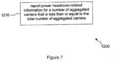
- Figure 7illustrates an embodiment of a method 1200 for reporting power headroom-related information for a plurality of aggregated carriers.
- power headroom-related informationis reported for a number of the aggregated carriers that is less than or equal to the total number of aggregated carriers.
- FIG. 8illustrates an example of a system 1300 that includes a processing component 1310 suitable for implementing one or more embodiments disclosed herein.
- the system 1300might include network connectivity devices 1320, random access memory (RAM) 1330, read only memory (ROM) 1340, secondary storage 1350, and input/output (1/0) devices 1360. These components might communicate with one another via a bus 1370. In some cases, some of these components may not be present or may be combined in various combinations with one another or with other components not shown.
- DSPdigital signal processor
- the processor 1310executes instructions, codes, computer programs, or scripts that it might access from the network connectivity devices 1320, RAM 1330, ROM 1340, or secondary storage 1350 (which might include various disk-based systems such as hard disk, floppy disk, or optical disk). While only one CPU 1310 is shown, multiple processors may be present. Thus, while instructions may be discussed as being executed by a processor, the instructions may be executed simultaneously, serially, or otherwise by one or multiple processors.
- the processor 1310may be implemented as one or more CPU chips.
- the network connectivity devices 1320may take the form of modems, modem banks, Ethernet devices, universal serial bus (USB) interface devices, serial interfaces, token ring devices, fiber distributed data interface (FDDI) devices, wireless local area network (WLAN) devices, radio transceiver devices such as code division multiple access (CDMA) devices, global system for mobile communications (GSM) radio transceiver devices, worldwide interoperability for microwave access (WiMAX) devices, and/or other well-known devices for connecting to networks.
- These network connectivity devices 1320may enable the processor 1310 to communicate with the Internet or one or more telecommunications networks or other networks from which the processor 1310 might receive information or to which the processor 1310 might output information.
- the network connectivity devices 1320might also include one or more transceiver components 1325 capable of transmitting and/or receiving data wirelessly.
- the RAM 1330might be used to store volatile data and perhaps to store instructions that are executed by the processor 1310.
- the ROM 1340is a non-volatile memory device that typically has a smaller memory capacity than the memory capacity of the secondary storage 1350. ROM 1340 might be used to store instructions and perhaps data that are read during execution of the instructions. Access to both RAM 1330 and ROM 1340 is typically faster than to secondary storage 1350.
- the secondary storage 1350is typically comprised of one or more disk drives or tape drives and might be used for non-volatile storage of data or as an over-flow data storage device if RAM 1330 is not large enough to hold all working data. Secondary storage 1350 may be used to store programs that are loaded into RAM 1330 when such programs are selected for execution.
- the I/O devices 1360may include liquid crystal displays (LCDs), touch screen displays, keyboards, keypads, switches, dials, mice, track balls, voice recognizers, card readers, paper tape readers, printers, video monitors, or other well-known input/output devices.
- the transceiver 1325might be considered to be a component of the I/O devices 1360 instead of or in addition to being a component of the network connectivity devices 1320.
Landscapes
- Engineering & Computer Science (AREA)
- Signal Processing (AREA)
- Computer Networks & Wireless Communication (AREA)
- Mobile Radio Communication Systems (AREA)
- Transmitters (AREA)
Description
- As used herein, the terms "user agent" and "UA" might in some cases refer to mobile devices such as mobile telephones, personal digital assistants, handheld or laptop computers, and similar devices that have telecommunications capabilities. Such a UA might consist of a device and its associated removable memory module, such as but not limited to a Universal Integrated Circuit Card (UICC) that includes a Subscriber Identity Module (SIM) application, a Universal Subscriber Identity Module (USIM) application, or a Removable User Identity Module (R-UIM) application. Alternatively, such a UA might consist of the device itself without such a module. In other cases, the term "UA" might refer to devices that have similar capabilities but that are not transportable, such as desktop computers, set-top boxes, or network appliances. The term "UA" can also refer to any hardware or software component that can terminate a communication session for a user. Also, the terms "user agent," "UA," "user equipment," "UE," "user device" and "user node" might be used synonymously herein.
- As telecommunications technology has evolved, more advanced network access equipment has been introduced that can provide services that were not possible previously. This network access equipment might include systems and devices that are improvements of the equivalent equipment in a traditional wireless telecommunications system. Such advanced or next generation equipment may be included in evolving wireless communications standards, such as long-term evolution (LTE). For example, an LTE system might include an Evolved Universal Terrestrial Radio Access Network (E-UTRAN) node B (eNB), a wireless access point, or a similar component rather than a traditional base station. As used herein, the term "access node" will refer to any component of a wireless telecommunications system, such as a traditional base station, a wireless access point, or an LTE eNB, that creates a geographical area of reception and transmission coverage allowing a UA to access other components in the system. An access node may comprise a plurality of hardware and software.
- LTE was standardized in Release 8 of the wireless telecommunications standards promoted by the 3rd Generation Partnership Project (3GPP). 3GPP Release 10 standards deal with LTE-Advanced or LTE-A technology. Under LTE-A, relays and other advanced components might be included in a wireless telecommunications network. A relay is a component in a wireless network that is configured to extend or enhance the coverage created by an access node or another relay. Although access nodes and relays may be distinct components with different capabilities and functions, for ease of reference, the term "access node" will be used herein to refer to either a relay or an access node as described above.
- The signals that carry data between UAs, relay nodes, and access nodes can have frequency, time, and coding parameters and other characteristics that might be specified by a network node. A connection between any of these elements that has a specific set of such characteristics can be referred to as a resource. The terms "resource," "communications connection," "channel," and "communications link" might be used synonymously herein. A network node typically establishes a different resource for each UA or other network node with which it is communicating at any particular time.
WO2006/019441 discloses a multicarrier CDMA system, whereby a packet stream is divided into one or more substreams depending on a selected number of carrier frequencies, and each substream is transmitted on a corresponding carrier frequency. The number of carrier frequencies is selectively varied during transmission of the packet data.
"PUSCH Power Control for LTE-Advanced", by Nokia Siemens Networks, 3GPP TSG RAN WG1 #56 Meeting, discloses the possibility to extend the principles of Rel' 8 uplink power control to LTE-Advanced.
"UL Transmission Power Control in LTE-A", by Samsung, 3GPP TSG RAN WG1 #56bis, discloses an overview for the application of transmission power control (TPC) for the PUSCH, the PUCCH, and the SRS in LIB-Advanced (LTE-A).
"DC-HSUPA impact on RAN2 specifications", by Qualcomm Europe, 3GPP TSG RAN WG2 #65bis, discloses the MAC, RLC and RRC areas with potential impact from the introduction of dual carrier operation on the uplink, after evaluating gains from any potential changes.
"3rd Generation Partnership Project; Technical Specification Group Radio Access Network; Medium Access Control (MAC) protocol specification", 3GPP TS 25.321, V7.5.0, specifies the MAC protocol.
"Remaining issues on Uplink Power Control for Carrier Aggregation", by Research In Motion UK Limited, 3GPP TSG RAN WG1 Meeting #59bis, discloses some issues to design detailed power control operation for LTE-A supporting carrier aggregation. - According to aspects to the present disclosure, there are provided methods, an access node, a user agent, and related computer-readable media according to the appended claims.
- For a more complete understanding of this disclosure, reference is now made to the following brief description, taken in connection with the accompanying drawings and detailed description, wherein like reference numerals represent like parts.
Figure 1 illustrates an aggregation of carriers.Figure 2 illustrates a procedure by which an access node grants a resource to a user agent.Figure 3 is a diagram of a power headroom and related quantities.Figure 4 is a diagram of a control element that could be used for transmitting power headroom-related information.Figure 5 is a diagram of a control element that could be used for transmitting power headroom-related information.Figure 6 illustrates an exemplary MAC control element.Figure 7 is a diagram illustrating a method for reporting power headroom related information for a plurality of aggregated carriers.Figure 8 illustrates a processor and related components suitable for implementing the several embodiments of the present disclosure.- It should be understood at the outset that although illustrative implementations of one or more embodiments of the present disclosure are provided below, the disclosed systems and/or methods may be implemented using any number of techniques, whether currently known or in existence The claimed invention corresponds to
fig. 7 and to the related text in the description, the other figures and the remaining text of the description are only intended to better explain the claimed invention. - In LTE-A, carrier aggregation might be used in order to support wider transmission bandwidths and hence increase the potential peak data rate to meet LTE-A requirements. In carrier aggregation, multiple component carriers are aggregated and can be allocated in a subframe to a UA as shown in
Figure 1 . In this example, eachcomponent carrier 110 has a width of 20 MHz and the total system bandwidth becomes 100 MHz. The UA may receive or transmit on a multiple of up to five component carriers depending on its capabilities. In addition, depending on the deployment scenario, carrier aggregation may occur with carriers located in the same band and/or carriers located in different bands. For example, one carrier may be located at 2 GHz and a second aggregated carrier may be located at 800 MHz. - In uplink transmissions, a UA transmits a power headroom report (PHR) and a buffer status report (BSR) to an access node in order to assist with uplink scheduling. The access node uses this information when it determines the amount of frequency resources and proper modulation and coding scheme (MCS) level for physical uplink shared channel (PUSCH) transmissions.
Figure 2 shows the general flow of an uplink transmission from aUA 210 to anaccess node 220. When new data arrives at the UA buffer, theUA 210, atevent 231, transmits a scheduling request on the physical uplink control channel (PUCCH) if there is no uplink PUSCH resource available for the initial transmission. Since theaccess node 220 does not know the current uplink channel conditions or the amount of pending data, theaccess node 220 schedules a small amount of uplink resources, as shown atevent 232. TheUA 210, atevent 233, then transmits a PHR and BSR using this initial uplink resource. With this additional information, theaccess node 220, atevent 234, can provide theUA 210 with a larger amount of uplink resources. Atevent 235, theUA 210 transmits to theaccess node 220 at a higher data rate according to the UA buffer status and the observed channel conditions. - As shown in
Figure 3 , the power headroom (PH) 310 is defined as the difference between the nominal UA maximum transmit power (Pcmax) 320 and the estimated power for PUSCH transmissions (Ppusch(i)) 330. Even when the same data rate is transmitted in two different situations, the PH values can be different depending on the current UA channel conditions. From the access node scheduler's point of view, a large PH means that the UA has more room to increase its power to accommodate a higher data rate transmission, while a small PH means that the UA cannot increase its data rate. - The 3GPP Technical Specification (TS) 36.213 defines the following equation which a UA can use to calculate the PH:

- This equation means that the PH is the remaining available transmission power, obtained by subtracting the uplink transmission power at the ith subframe from the maximum allowable transmission power. The parameters are defined as follows.
- PCMAX is the configured maximum UA transmission power.
- MPUSH(i) is the bandwidth of the PUSCH resource assignment expressed in number of resource blocks scheduled for subframe i.
- PO_PUSH(j) is a parameter composed of the sum of a cell-specific nominal component and a UA-specific component provided by higher layers.
- α(j) is defined in 3GPP TS 36.213.
- PL is the downlink path loss estimate calculated in the UA in dB.
- ΔTF(i) is the offset with respect to the transport format.
- f(i) is the power control adjustment.
- In LTE-A systems, UAs might report their PH to an access node to assist with uplink scheduling as in the case with LTE systems. However, the PH reporting approach used in LTE, where PH is the difference between the maximum allowable and current uplink transmission powers, may not be appropriate in LTE-A. An LTE-A UA is able to transmit using multiple carriers simultaneously, and scheduling might be performed on a per-carrier basis with different MCS levels. If each carrier is constrained to use the same uplink transmit power, one PH report may be sufficient. However, the uplink transmit power would be expected to be different for each carrier because some power-related parameters might vary for different carriers.
- For example, the path loss can be different if the carriers are located in different bands. Assuming two example carriers are located at 2 GHz and 800 MHz, respectively, the expected statistical difference in path loss can be calculated as a function of the frequency based on the path loss model in 3GPP Technical Report (TR) 25.942. In this model, the path loss L is given as 40(1 - 4×10⁻³ Dhb) Log10(R) - 18Log10(Dhb) + 21 Log10(f) + 80 dB, where f is the frequency in MHz, Dhb is the access node antenna height in meters (in 3GPP, 15m is assumed), and R is the distance between the access node and the UA in kilometers. For 2 GHz, L = 128.1 + 37.6 Log10(R). For 800 MHz, L = 119.7 + 37.6 Log10(R). So, provided that there are no other factors, the expected mean difference in path loss between 2 GHz and 800 MHz will be about 9 dB. It is noted that this difference has been calculated with a statistical model. In an actual deployment, it would be not be realistic for an access node to be able to accurately predict the path loss difference between bands due to different propagation characteristics as a function of the frequency. For example, higher frequency carriers generally attenuate faster as a function of distance and are also more likely to be attenuated by environmental factors such as building penetration, foliage, rain, etc.
- Also, the power control adjustment, f(i), might be different for different carriers. An access node could transmit individual TPC (Transmit Power Control) commands per carrier or a single combined TPC command for all of the carriers. Even though the access node originates the TPC commands, it would be difficult for the access node to correctly track the currentf(i) values per carrier due to possible TPC signaling errors and/or TPC signals that were mis-detected by the UA.
- In addition,PO_PUSCH might vary for different carriers.PO_PUSCH is a cell- and UA-specific parameter that adjusts the target signal to interference-plus-noise ratio (SINR) based on the interference level. Since each component carrier is scheduled independently, each carrier might experience a different inter-cell interference level. The loading of different carriers may be different depending on the scheduling in the neighbor cells. For example, the access node might schedule cell-edge UAs on one carrier and more centrally-located UAs on the remaining carriers. In addition, the network topology may result in different neighboring cells having different carriers available. For instance, one cell may have five carriers in total, but a neighboring cell that is expected to be less lightly loaded may only be configured with a maximum of three carriers.
- Also,α(j) might be different for different carriers.α(j) is a cell-specific parameter intended to improve cell throughput under small interference levels. This parameter can be varied based on the cell loading and/or on the UA distribution within a cell.
- For these and other reasons, the uplink transmit power, and therefore the power headroom, might be different for each carrier in a set of aggregated carriers. To reflect the need for individual PH values per carrier or per band, the PH of all carriers could be reported to the access node. However, this could result in excessive signaling overhead, since it may not be necessary to report the PH for every carrier. In an embodiment, various schemes are provided for efficiently transmitting per-carrier PH values for a set of aggregated carriers in order to reduce signaling overhead.
- Most of the factors determining a PH value are carrier-specific but, other than path loss (and possibly the current power control correction), the access node is typically aware of these parameters. Therefore, if the access node is made aware of the path loss for each carrier, the access node can calculate a PH for each carrier. A UA could report an observed path loss in a higher-layer measurement report, but such a report may not be sent frequently enough because higher-layer messages tend to be larger and generally incur some delay before being triggered. Consequently, it may be advantageous for the UA to report a separate PH value to the access node for each carrier. However, it may be unnecessary to report separate PH values for all carriers given that the path losses of carriers located in the same frequency band are typically similar.
- In an embodiment, to avoid additional signaling overhead, the number of carriers for which the PH or PH-related information is reported is less than or equal to the total number of configured carriers. For notational convenience, a carrier for which a PH or PH-related information is reported is referred to herein as a "reporting carrier". In an embodiment, there are two approaches to configure which carriers are reporting carriers.
- In an embodiment, an access node configures the carrier set to be reported. The access node selects the carriers for which PH reporting will be performed and communicates this decision to the UA via radio resource control (RRC) signaling or media access control (MAC) control elements. This approach provides additional freedom to the access node because the access node can select the reporting carriers regardless of whether those carriers are located in the same or different bands. The access node uses a bitmap to indicate which carriers' PHs should be reported.
- In LTE, a PH report might be transmitted at periodic intervals and/or when a triggering event occurs. According to 3GPP TS 36.321, a PH report is triggered if any of the following events occur: theprohibitPHR-Timer expires or has expired and the path loss has changed more thandl-PathlossChange dB since the last power headroom report, when the UA has uplink resources for a new transmission; theperiodicPHR-Timer expires, in which case the PHR is referred to as a "Periodic PHR"; upon configuration and reconfiguration of a Periodic PHR.
- In an embodiment, these criteria are expanded to support carrier aggregation under LTE-A. The triggers related to the expiration of theperiodicPHR-Timer and the configuration and reconfiguration of a Periodic PHR might remain the same, but the trigger related to the expiration of theprohibitPHR-Timer might be modified. More specifically, in LTE-A, a PH report is triggered if theprohibitPHR-Timer expires or has expired and the path loss of any reporting carrier has changed more thandl-PathlossChange dB since the last power headroom report, when the UA has uplink resources for a new transmission. The PH reporting scheme could be such that only reporting carriers that satisfy thisdl-PathlossChange criterion actually report their new PH values. That is, not all configured reporting carriers would actually include their PH values in the PH report.
- It has been discussed that the number of active carriers currently used by a UA can be configured semi-statically. In this case, when a new carrier is added to an aggregation of carriers, it may be desirable to report its PH as soon as possible to assist with uplink scheduling on that carrier. Therefore, in an embodiment, as one additional criterion for LTE-A PH reporting, a PH report is triggered when a UA receives a new carrier configuration from the access node and/or a new PH reporting configuration that includes a new reporting carrier.
- As mentioned previously, a UA could transmit a PH report to an access node via RRC signaling or via MAC control elements. Since the RRC signaling approach might incur additional delay and signaling overhead, the MAC control element approach may be preferable. The following alternatives for transmitting a PH or PH-related information are based on the MAC control element approach. If there is no explicit indication otherwise, the PH reporting discussed in the following alternatives is triggered according to the criteria described above.
- In one alternative, when PH reporting is triggered, a UA transmits the PHs for all of the reporting carriers. For example, if there are four reporting carriers, when the observed path loss difference for one of the reporting carriers exceeds the configured threshold (that is, the path loss of a reporting carrier has changed more thandl-PathlossChange dB), the UA transmits the PHs for all four of the reporting carriers.
Figure 4 illustrates an example of aMAC control element 400 that could be used for transmitting the PHs of all reporting carriers. Thecontrol element 400 consists of three byte-aligned octets 410. The number of PH values equals the number of reporting carriers. In this example four reporting carriers have been configured. The length of the PH values is six bits, as in LTE. Each PHk represents the PH of carrier k. In some embodiments, if the allocated UL resources cannot accommodate the MAC control element of all PHs plus its subheader as a result of logical channel prioritization, then the UA can decide not to transmit all PHs or transmit PHs of a subset of carriers in the MAC control element to be accommodated in the allocated UL resources. The UA can select carriers based on the logical or physical carrier indexing. In one embodiment, the UA can select a carrier based on the priority of the carrier. For example, the UA can transmit the PH of the uplink anchor carrier or a carrier used to transmit data with a high quality of service (QoS).- In yet another alternative for reporting LTE-A power headroom via a MAC control element, a UA transmits the PH of only a certain reporting carrier or of only certain reporting carriers. The disadvantage of transmitting the PH for all reporting carriers, as described in the first alternative given above, is that PH information may be reported unnecessarily. In an embodiment, to reduce signaling overhead, the UA transmits PH information only for a carrier or carriers for which a specific event trigger occurs or when that carrier's PUSCH is scheduled. Differentdl-PathlossChange, periodicPHR-Timer, and/or prohibitPHR-Timer can be configured for each carrier or for a subset of carriers. In case where multiple events are triggered, PHs of all triggered carriers can be transmitted. For example, when the path loss difference is larger than a preconfigured threshold in
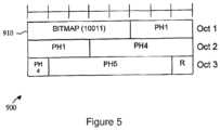
carrier # 1, UA would transmit the PH only forcarrier # 1. To indicate to the access node which reporting carriers' PHs are being transmitted, a bitmap is included with a PH report. In some embodiments, if the allocated UL resources cannot accommodate the MAC control element of all PHs plus its subheader as a result of logical channel prioritization, then the UA can decide not to transmit all PHs or transmit PHs of a subset of carriers in the MAC control element to be accommodated in the allocated UL resources. The UA can select carriers based on the logical or physical carrier indexing. In one embodiment, the UA can select a carrier based on the priority of carrier. For example, the UA can transmit PH of the uplink anchor carrier or carrier transmitting the high QoS data. - An example of this technique is shown in Figure 59, where a
MAC control element 900 includes abitmap 910 with a length equal to the number of reporting carriers. In this case, there are five reporting carriers, so thebitmap 910 includes five bits. The bit in the kth position indicates whether or not the PH value of the kth carrier is included in thecontrol element 900. For example, "1" may mean that the corresponding PH value is included, while "0" may mean that the PH value is not included. In this example, the first, fourth, and fifth bits of thebitmap 910 are set to "1", so PH values for the first, fourth, and fifth carriers are included in thecontrol element 900. - It should be noted that a combination of the above approaches can be used depending on the operation. For example, a UA might report PH values for all carriers periodically. Meanwhile, in the event-triggered case, the UA reports only for the selected carriers in order to reduce the signaling overhead.
- In an embodiment, to support carrier aggregation, the calculation used to obtain PH in an LTE-based environment is modified to be carrier-specific in an L TE-A-based environment. An example of such a modified PH equation for calculating the PH value for LTE-A is given below.

- With the current LTE PH equation, scheduling information is needed to calculate PH. For example, the number of scheduled resource blocks (MPUSCH,k(i)) needs to be known and the transport block size is needed in order to calculate ΔTF,k(i). In an LTE-Abased environment with aggregated carriers, a UA may not have a current PUSCH allocation for a particular reporting carrier. Such a UA would not have the necessary scheduling information and therefore could not perform the PH calculation. In an embodiment, the UA makes certain assumptions in this situation in order to calculate and report PH values for any non-scheduled carriers. One of three different techniques might be used.
- In one technique, the UA copies the resource configuration for a scheduled carrier. At least one carrier must be scheduled in order for the UA to be able to transmit a PH report. Any non-scheduled reporting carriers can use the same scheduling configuration (i.e., the number of resource blocks and the transport block size), as given for a selected scheduled carrier, in order to calculate a PH value. Possible methods for selecting a scheduled carrier whose scheduling configuration would be "copied" could be to select the nearest carrier as measured by carrier frequency or to select the scheduled carrier with the lowest or highest carrier frequency.
- In another technique, the configuration of the Sounding Reference Signal (SRS) transmission is used. The SRS is transmitted periodically from the UA and is used by the access node to detect the UA channel situation. For frequency-selective scheduling, the access node configures the UA to transmit SRS in each carrier. The number of resource blocks of the SRS transmission is semi-statically configured and ΔTF,k(i) is set to zero, so the UA is typically aware of these values. Since both the UA and access node know the SRS transmission parameters, the number of resource blocks of the SRS transmission can be used if a PUSCH transmission is not scheduled for a particular carrier.
- In another technique, a reference configuration is predefined. Fixed reference values for the number of resource blocks and the transport block size can be predefined or configured by higher-layer signaling and then used in the calculation of a PH value for a non-scheduled carrier.
- When the PUSCH and the PUCCH are configured for simultaneous transmission, the PUCCH-related PH may need to be transmitted to indicate that the transmit power used for the PUCCH-related PH can be the PH only for the PUCCH or can be a combined PUCCH and PUSCH PH. If the access node receives only the PUSCH PH, it may be difficult to exactly estimate the allowable PUSCH power when the PUSCH and PUCCH are transmitted simultaneously, because the sum of PUSCH and PUCCH power is limited not to exceed the maximum transmit power. In one embodiment, the UA transmits the PUCCH-related PH in a MAC control element when PH reporting is triggered and a PUSCH resource is scheduled. When the PUCCH is transmitted in the same subframe in which the PUSCH resource is allocated, the PUCCH-related PH is calculated by the UA based on the actual transmit power of the PUCCH. In one embodiment, the calculated PUCCH-related PH is inserted in the MAC control element and transmitted to the access node. However, it can happen that the PUCCH is not transmitted when the PUCCH-related PH is reported, because PUCCH transmission is independent of PUSCH transmission. In this case, the UA cannot calculate the PH because the PUCCH transmit power is not defined when the PUCCH is not transmitted. One solution is to assume a reference configuration among different PUCCH formats when the UA transmits the PUCCH-related PH and the PUCCH is not transmitted. This reference configuration can be predefined in the specification or configured by higher layer signaling. The higher layer signaling could be UA-specific signaling or broadcast signaling. For example, the reference configuration could be one of the PUCCH formats from 3rd Generation Partnership Project (3GPP) Technical Specification (TS) 36.211. For example, the reference configuration could be PUCCH format 1 A from TS 36.211. In some embodiments, the PUCCH format requiring the most transmission power is used as the reference configuration. When using a reference configuration, the UA estimates the transmission power needed to transmit the PUCCH assuming it were to transmit the PUCCH using the reference configuration. It then uses this estimated transmission power to calculate the PUCCH-related PH.
- For example, the following equation may be used in the two cases discussed, with the second equation using PUCCH format 1 a as the reference configuration:

- In the previous equation, it is assumed that PH is reported only for the PUCCH. For the combined PUCCH and PUSCH PH case, the following equation can be used:

- In another embodiment, the UA assumes the fixed value for the parameters which are variable depending on the transmitted PUCCH transmission. According to the equation to set the PUSCH transmission power described in 3GPP TS 36.213,h(nCQI, nHARQ) and ΔF_PUCCH(F) are different for different PUCCH formats. When the PUCCH is not transmitted, the UA uses reference values for these parameters, where the reference value can be predefined in the specification or configured by higher layer signaling. For example, if the UA assumes bothh(nCQI, nHARQ) and ΔF_PUCCH(F) as 0, the above equation can be used. Other non-zero values can also be used.
Figure 6 illustrates an exemplary MAC control element wherein the PUSCH PH and PUCCH-related PH are transmitted in a single MAC control element. InFigure 6 , four reserved bits are included inoctet 1, six bits are used to represent the PUSCH PH and six bits are used to represent the PUCCH-related PH.- In some embodiments, one MAC control element is used to represent the PUSCH PH and another MAC control element is used to represent the PUCCH-related PH. In some embodiments, if the allocated UL resources cannot accommodate the combined MAC control element (PUCCH-related PH + PUSCH PH) plus its subheader as a result of logical channel prioritization, then the UA only transmits one MAC control element containing the PUSCH PH.
- In some embodiments, the access node configures whether PUCCH-related PH reporting should be performed using broadcast signaling or dedicated (UA-specific) signaling. For example, the access node can configure some UAs to report PUCCHrelated PH and PUSCH PH. These two reports can be transmitted from the UA using a single MAC control element. The access node can configure other UAs to report only PUSCH PH. This one report can be transmitted from the UA using a single MAC control element. The configuration can be based on UA capability, scheduling algorithms, etc.
- Combinations of the above embodiments can also be used. For example, a UA may be configured to report PUSCH PH for one or multiple carriers and PUCCH-related PH for one or multiple carriers. One or multiple MAC control elements can be used to report the required PH information.
- As mentioned above, one of the factors included in the calculation of power headroom is the downlink path loss. When multiple downlink component carriers are aggregated, it may not be clear which of the downlink component carriers is to be used for deriving path loss and thus for deriving the power headroom. For example, it may not be desirable to calculate path loss on a downlink component carrier that has been deactivated. In an embodiment, two alternatives are provided for determining which downlink component carrier is to be used for deriving path loss. In one alternative, the determination of which downlink component carrier is to be used for path loss derivation is based on a downlink component carrier that is linked to an uplink component carrier in the broadcast system information. In another alternative, the determination of which downlink component carrier is to be used for path loss derivation is based on a downlink component carrier that that has been designated for path loss derivation.
- Details of how to derive the path loss (PL) value in a carrier aggregation scenario are now provided. The PL value is required to calculate the PH value at uplink carriers as shown in the following equation.

- PL is the downlink path loss estimate derived by the UA, and PL = referenceSignalPower - higher layer filtered RSRP (Reference Signal Received Power), where referenceSignalPower is provided by higher layers and RSRP is measured in the UA and filtered with the higher layer filter configuration defined by higher layers.
- Since only one DL Component Carrier (CC) and one UL CC are supported in Release-8, it is preferable that PL be derived from the DL CC on which the UA measures RSRP. In carrier aggregation, however, a UA can be configured to receive multiple DL CCs, and it may be possible to refer to any DL CC for path loss derivation, although there is a cell-specific linkage between DL CC and UL CC for idle mode UAs, and this linkage is typically signaled in the system information. Therefore, it may be helpful to define which of the multiple DL CCs should be used for PL derivation.
- There are two aspects to be considered when defining the UA operation to determine the DL CC to be used for PL derivation. In the first aspect, the DL CC may not always be activated. In carrier aggregation, multiple DL CCs may be configured for a UA supporting carrier aggregation. These configured DL CCs can be activated or deactivated via MAC signaling. Actual downlink data is scheduled only to the activated DL CCs. This means that the UA may not need to receive PDCCH or PDSCH on the deactivated DL CCs. In this case, to save UA battery power, the UA could stop receiving all DL transmissions on the deactivated DL CCs. If the UA is implemented in this way, it would also be desirable not to derive PL on a deactivated CC even though that DL CC has been designated for PL derivation (especially if RSRP measurement on a deactivated CC consumes UA processing power). One exception would be that the UA could measure RSRP on a deactivated CC if this measurement is explicitly configured by higher layer signaling.
- In the second aspect, a different DL CC can be used other than the linked DL CC for PL derivation. To compensate for the difference between the PL derived with a different DL CC and the actual PL for PH calculation of a UL CC, an offset value can be signaled by the access node. The access node could generate this offset based on measurement reporting or a statistical model or field testing. However, the PL may not be correct in the actual environment, especially if the DL CC being referenced is located in a different frequency band from the UL CC and the UA is moving.
- To clarify the description of the proposed UA operation for PL derivation, the following carrier types are introduced. One type can be referred to as the Downlink Primary Component Carrier (DL PCC). In this case, one of the DL CCs is configured as the DL PCC, and the DL PCC is never deactivated. Another type can be referred to as the Paired DL CC. This is a DL CC cell specifically linked to a UL CC in the broadcast system information. Another type can be referred to as the DL CC_pl. This is a DL CC used for PL derivation. Each UL CC could be configured to reference one DL CC_pl for PL derivation. With these definitions in place, two alternatives can be provided.
- In the first alternative, the UA uses the paired DL CC for PL derivation if that paired DL CC is activated or configured for measurement. Since the paired DL CC for each UL CC is signaled in the system information, additional signaling to indicate DL CC_pl would not be required. When the paired DL CC is deactivated and has not been configured for measurement, and the UL CC still needs to be transmitted, there are three possible approaches. In a first approach, the UA may still derive PL from the (deactivated) paired DL CC. In this case, the UA still measures RSRP on the paired DL CC. In a second approach, the UA may derive PL from another DL CC in the same band where the other DL CC is activated or where measurement has been configured. In a third approach, the UA derives PL from another DL CC provided by the access node. The reference carrier may be implicit, such as the DL PCC. The offset between DL CCs and PCC may need to be signaled. Since PL difference is likely to happen when PCC and DL CC are in different bands, the offset can be signaled if the corresponding DL CC is in a different band than PCC. Alternatively, the offset between frequency bands can be signaled.
- One of these approaches can be selected or all three approaches can be defined. When all approaches can be applicable, it may be preferable to prioritize using the first or second approach, considering the accuracy of PL derivation. In other words, if the paired DL CC is not activated and not configured for measurement, the UA may still derive PL from the paired DL CC or may derive PL from another DL CC in the same band where the DL CC is either activated or measurement is configured. Otherwise, the UA might use the offset (and the reference DL CC where the offset should be applied) provided by the access node.
- In a second alternative, the access node can configure the UA to reference any DL CC for DL CC_pl. An offset may not be needed if the PL of DL CC_pl and the actual PL required for the UL CC are similar. This might happen if they are located in the same frequency band. Otherwise, the offset could be signaled. Two different UA operations might be used depending on whether the DL CC_pl is in the same frequency band as the UL CC or not. In the case where DL CC_pl is in the same frequency band as the UL CC, the UA could use the DL CC_pl for PL derivation if that DL CC_pl is activated or configured for measurement. When DL CC_pl is deactivated but the UL CC still needs to be transmitted, the UA could apply the same approaches as described with regard to the first alternative. In the case where DL CC_pl is in a different frequency band, the UA may use another DL CC, e.g., the paired DL CC or DL CC in the same frequency band with the UL CC if this DL CC is activated or configured for measurement. Otherwise, the UA could derive the PL with DL CC_pl and an offset. This is because the PL derived by the paired DL CC or DL CC in the same frequency band might be more accurate than the PL derived by the DL CC_pl with an offset. The same PL derivation method could be applied to the uplink transmit power setting for uplink channels, e.g., PUSCH or PUCCH, as well as the PH value calculation in each UL CC.
Figure 7 illustrates an embodiment of amethod 1200 for reporting power headroom-related information for a plurality of aggregated carriers. Atblock 1210, power headroom-related information is reported for a number of the aggregated carriers that is less than or equal to the total number of aggregated carriers.- The
UA 210, theaccess node 220, and other components described above might include a processing component that is capable of executing instructions related to the actions described above.Figure 8 illustrates an example of asystem 1300 that includes aprocessing component 1310 suitable for implementing one or more embodiments disclosed herein. In addition to the processor 1310 (which may be referred to as a central processor unit or CPU), thesystem 1300 might includenetwork connectivity devices 1320, random access memory (RAM) 1330, read only memory (ROM) 1340,secondary storage 1350, and input/output (1/0)devices 1360. These components might communicate with one another via abus 1370. In some cases, some of these components may not be present or may be combined in various combinations with one another or with other components not shown. These components might be located in a single physical entity or in more than one physical entity. Any actions described herein as being taken by theprocessor 1310 might be taken by theprocessor 1310 alone or by theprocessor 1310 in conjunction with one or more components shown or not shown in the drawing, such as a digital signal processor (DSP) 1380. Although theDSP 1380 is shown as a separate component, theDSP 1380 might be incorporated into theprocessor 1310. - The
processor 1310 executes instructions, codes, computer programs, or scripts that it might access from thenetwork connectivity devices 1320,RAM 1330,ROM 1340, or secondary storage 1350 (which might include various disk-based systems such as hard disk, floppy disk, or optical disk). While only oneCPU 1310 is shown, multiple processors may be present. Thus, while instructions may be discussed as being executed by a processor, the instructions may be executed simultaneously, serially, or otherwise by one or multiple processors. Theprocessor 1310 may be implemented as one or more CPU chips. - The
network connectivity devices 1320 may take the form of modems, modem banks, Ethernet devices, universal serial bus (USB) interface devices, serial interfaces, token ring devices, fiber distributed data interface (FDDI) devices, wireless local area network (WLAN) devices, radio transceiver devices such as code division multiple access (CDMA) devices, global system for mobile communications (GSM) radio transceiver devices, worldwide interoperability for microwave access (WiMAX) devices, and/or other well-known devices for connecting to networks. Thesenetwork connectivity devices 1320 may enable theprocessor 1310 to communicate with the Internet or one or more telecommunications networks or other networks from which theprocessor 1310 might receive information or to which theprocessor 1310 might output information. Thenetwork connectivity devices 1320 might also include one ormore transceiver components 1325 capable of transmitting and/or receiving data wirelessly. - The
RAM 1330 might be used to store volatile data and perhaps to store instructions that are executed by theprocessor 1310. TheROM 1340 is a non-volatile memory device that typically has a smaller memory capacity than the memory capacity of thesecondary storage 1350.ROM 1340 might be used to store instructions and perhaps data that are read during execution of the instructions. Access to bothRAM 1330 andROM 1340 is typically faster than tosecondary storage 1350. Thesecondary storage 1350 is typically comprised of one or more disk drives or tape drives and might be used for non-volatile storage of data or as an over-flow data storage device ifRAM 1330 is not large enough to hold all working data.Secondary storage 1350 may be used to store programs that are loaded intoRAM 1330 when such programs are selected for execution. - The I/
O devices 1360 may include liquid crystal displays (LCDs), touch screen displays, keyboards, keypads, switches, dials, mice, track balls, voice recognizers, card readers, paper tape readers, printers, video monitors, or other well-known input/output devices. Also, thetransceiver 1325 might be considered to be a component of the I/O devices 1360 instead of or in addition to being a component of thenetwork connectivity devices 1320.


Claims (11)
- A method at an access node (220) for a wireless telecommunications system, the method comprising:receiving, from an user agent, UA (210), within a bitmap (910), power headroom-related information for a number of aggregated carriers that is less than or equal to a total number of aggregated carriers,wherein each bit in the bitmap corresponds to one of the aggregated carriers, one value in the bitmap indicating that the power headroom-related information for a corresponding carrier is being transmitted, and another value in the bitmap indicating that the power headroom-related information for a corresponding carrier is not being transmitted,wherein the bitmap has a length equal to a number of reporting carriers among the number of aggregated carriers, andwherein the power headroom-related information comprises one of power headroom and path loss information, for at least one of the aggregated carriers;specifying a set of carriers from the total number of aggregated carriers for which the power headroom-related information is to be reported; andinforming the UA of the set of carriers for which the power headroom-related information is to be reported.
- The method of claim 1, wherein the power headroom-related information is received for a representative carrier in a frequency band, the representative carrier being one of the aggregated carriers, and wherein the representative carrier is selected based on a rule known by the access node and the UA from which the access node receives the power headroom-related information.
- The method of claim 1, wherein the power headroom-related information is received as a result of one of:a difference in path loss between consecutive measurements of path loss for one of the carriers exceeding a threshold;a transmission on a carrier's physical uplink shared channel being scheduled; anda power headroom for a carrier exceeding a threshold.
- The method of claim 1, wherein a physical uplink control channel, PUCCH, related power headroom is received when power headroom reporting is triggered and a physical uplink shared channel, PUSCH, resource is scheduled.
- The method of claim 4, wherein, when the PUCCH is received in the same subframe in which the PUCCH related power headroom is reported, the PUCCH related power headroom is calculated based on an actual transmit power of the PUCCH.
- An access node (220, 1300), for a wireless telecommunications system, configured to perform the method of any of claims 1 to 5.
- A computer-readable medium (1330) containing instructions which, when executed by an access node (1300) for a wireless telecommunications system, cause the access node to perform the method of any of claims 1 to 5.
- A method at a user agent, UA (210), comprising:transmitting (1210), to an access node (220) for a wireless telecommunications system, within a bitmap, power headroom-related information for a number of aggregated carriers that is less than or equal to a total number of aggregated carriers,wherein the power headroom-related information comprises one of power headroom and path loss information, for at least one of the aggregated carriers,wherein each bit in the bitmap corresponds to one of the aggregated carriers, one value in the bitmap indicating that the power headroom-related information for a corresponding carrier is being transmitted, and another value in the bitmap indicating that the power headroom-related information for a corresponding carrier is not being transmitted, andwherein the bitmap has a length equal to a number of reporting carriers among the number of aggregated carriers; andreceiving information, from the access node, about a specified set of carriers for which the power headroom-related information is to be reported.
- The method of claim 8, wherein the UA transmits the power headroom-related information to the access node as a result of one of:a difference in path loss between consecutive measurements of path loss for one of the carriers exceeding a threshold;a transmission on a carrier's physical uplink shared channel being scheduled; anda power headroom for a carrier exceeding a threshold.
- A user agent, UA (210, 1300), configured to perform the method of claim 8 or claim 9.
- A computer-readable medium (1330) containing instructions which, when executed by a user agent, UA (1300), cause the UA to perform the method of claim 8 or claim 9.
Applications Claiming Priority (10)
| Application Number | Priority Date | Filing Date | Title |
|---|---|---|---|
| US18065209P | 2009-05-22 | 2009-05-22 | |
| US30392010P | 2010-02-12 | 2010-02-12 | |
| US32021110P | 2010-04-01 | 2010-04-01 | |
| EP13151125.5AEP2582189B1 (en) | 2009-05-22 | 2010-05-21 | Reporting power headroom for aggregated carriers |
| EP17158544.1AEP3240335B1 (en) | 2009-05-22 | 2010-05-21 | Reporting power headroom for aggregated carriers |
| EP15172887.0AEP2945440B1 (en) | 2009-05-22 | 2010-05-21 | Reporting power headroom for aggregated carriers |
| PCT/US2010/035845WO2010135698A2 (en) | 2009-05-22 | 2010-05-21 | Reporting power headroom for aggregated carriers |
| EP10730882AEP2433448B1 (en) | 2009-05-22 | 2010-05-21 | Reporting power headroom for aggregated carriers |
| EP20151845.3AEP3657867B1 (en) | 2009-05-22 | 2010-05-21 | Reporting power headroom for aggregated carriers |
| EP18182273.5AEP3404968B1 (en) | 2009-05-22 | 2010-05-21 | Reporting power headroom for aggregated carriers |
Related Parent Applications (7)
| Application Number | Title | Priority Date | Filing Date |
|---|---|---|---|
| EP15172887.0ADivisionEP2945440B1 (en) | 2009-05-22 | 2010-05-21 | Reporting power headroom for aggregated carriers |
| EP18182273.5ADivisionEP3404968B1 (en) | 2009-05-22 | 2010-05-21 | Reporting power headroom for aggregated carriers |
| EP17158544.1ADivisionEP3240335B1 (en) | 2009-05-22 | 2010-05-21 | Reporting power headroom for aggregated carriers |
| EP10730882ADivisionEP2433448B1 (en) | 2009-05-22 | 2010-05-21 | Reporting power headroom for aggregated carriers |
| EP13151125.5ADivisionEP2582189B1 (en) | 2009-05-22 | 2010-05-21 | Reporting power headroom for aggregated carriers |
| EP20151845.3ADivisionEP3657867B1 (en) | 2009-05-22 | 2010-05-21 | Reporting power headroom for aggregated carriers |
| EP20151845.3ADivision-IntoEP3657867B1 (en) | 2009-05-22 | 2010-05-21 | Reporting power headroom for aggregated carriers |
Publications (2)
| Publication Number | Publication Date |
|---|---|
| EP3989651A1 EP3989651A1 (en) | 2022-04-27 |
| EP3989651B1true EP3989651B1 (en) | 2024-02-14 |
Family
ID=42562803
Family Applications (9)
| Application Number | Title | Priority Date | Filing Date |
|---|---|---|---|
| EP13151125.5AActiveEP2582189B1 (en) | 2009-05-22 | 2010-05-21 | Reporting power headroom for aggregated carriers |
| EP21215914.9AActiveEP3989651B1 (en) | 2009-05-22 | 2010-05-21 | Reporting power headroom for aggregated carriers |
| EP10730882AActiveEP2433448B1 (en) | 2009-05-22 | 2010-05-21 | Reporting power headroom for aggregated carriers |
| EP18182273.5AActiveEP3404968B1 (en) | 2009-05-22 | 2010-05-21 | Reporting power headroom for aggregated carriers |
| EP15172887.0AActiveEP2945440B1 (en) | 2009-05-22 | 2010-05-21 | Reporting power headroom for aggregated carriers |
| EP20151845.3AActiveEP3657867B1 (en) | 2009-05-22 | 2010-05-21 | Reporting power headroom for aggregated carriers |
| EP17158544.1AActiveEP3240335B1 (en) | 2009-05-22 | 2010-05-21 | Reporting power headroom for aggregated carriers |
| EP10730881AActiveEP2433447B1 (en) | 2009-05-22 | 2010-05-21 | Power headroom reporting for carrier aggregation |
| EP10730883AWithdrawnEP2433449A2 (en) | 2009-05-22 | 2010-05-21 | System and method for transmitting power headroom information for aggregated carriers |
Family Applications Before (1)
| Application Number | Title | Priority Date | Filing Date |
|---|---|---|---|
| EP13151125.5AActiveEP2582189B1 (en) | 2009-05-22 | 2010-05-21 | Reporting power headroom for aggregated carriers |
Family Applications After (7)
| Application Number | Title | Priority Date | Filing Date |
|---|---|---|---|
| EP10730882AActiveEP2433448B1 (en) | 2009-05-22 | 2010-05-21 | Reporting power headroom for aggregated carriers |
| EP18182273.5AActiveEP3404968B1 (en) | 2009-05-22 | 2010-05-21 | Reporting power headroom for aggregated carriers |
| EP15172887.0AActiveEP2945440B1 (en) | 2009-05-22 | 2010-05-21 | Reporting power headroom for aggregated carriers |
| EP20151845.3AActiveEP3657867B1 (en) | 2009-05-22 | 2010-05-21 | Reporting power headroom for aggregated carriers |
| EP17158544.1AActiveEP3240335B1 (en) | 2009-05-22 | 2010-05-21 | Reporting power headroom for aggregated carriers |
| EP10730881AActiveEP2433447B1 (en) | 2009-05-22 | 2010-05-21 | Power headroom reporting for carrier aggregation |
| EP10730883AWithdrawnEP2433449A2 (en) | 2009-05-22 | 2010-05-21 | System and method for transmitting power headroom information for aggregated carriers |
Country Status (6)
| Country | Link |
|---|---|
| US (11) | US8351359B2 (en) |
| EP (9) | EP2582189B1 (en) |
| CA (6) | CA2763448C (en) |
| ES (4) | ES2979351T3 (en) |
| FI (1) | FI3989651T3 (en) |
| WO (3) | WO2010135697A2 (en) |
Families Citing this family (131)
| Publication number | Priority date | Publication date | Assignee | Title |
|---|---|---|---|---|
| US8095515B2 (en)* | 2008-03-19 | 2012-01-10 | Semmle Limited | Approximating relation sizes using field dependencies |
| TWI542241B (en) | 2008-12-03 | 2016-07-11 | 內數位專利控股公司 | Method and apparatus for reporting power headroom |
| US8848594B2 (en) | 2008-12-10 | 2014-09-30 | Blackberry Limited | Method and apparatus for discovery of relay nodes |
| US8355388B2 (en)* | 2008-12-17 | 2013-01-15 | Research In Motion Limited | System and method for initial access to relays |
| US8040904B2 (en)* | 2008-12-17 | 2011-10-18 | Research In Motion Limited | System and method for autonomous combining |
| US8311061B2 (en) | 2008-12-17 | 2012-11-13 | Research In Motion Limited | System and method for multi-user multiplexing |
| US8402334B2 (en) | 2008-12-17 | 2013-03-19 | Research In Motion Limited | System and method for hybrid automatic repeat request (HARQ) functionality in a relay node |
| US8335466B2 (en) | 2008-12-19 | 2012-12-18 | Research In Motion Limited | System and method for resource allocation |
| US8265128B2 (en) | 2008-12-19 | 2012-09-11 | Research In Motion Limited | Multiple-input multiple-output (MIMO) with relay nodes |
| US8446856B2 (en) | 2008-12-19 | 2013-05-21 | Research In Motion Limited | System and method for relay node selection |
| US8982801B2 (en)* | 2009-02-09 | 2015-03-17 | Interdigital Patent Holdings, Inc. | Apparatus and method for uplink power control for a wireless transmitter/receiver unit utilizing multiple carriers |
| EP2582189B1 (en) | 2009-05-22 | 2015-07-08 | BlackBerry Limited | Reporting power headroom for aggregated carriers |
| JP5360207B2 (en)* | 2009-06-03 | 2013-12-04 | 日本電気株式会社 | Base station apparatus, edge user estimation method and program |
| CN101932019B (en)* | 2009-06-19 | 2015-06-03 | 中兴通讯股份有限公司 | Method, terminal and network system for reporting buffer status report |
| CN101932045B (en)* | 2009-06-24 | 2014-11-05 | 中兴通讯股份有限公司 | Reporting method for measurement result in carrier aggregation and user equipment |
| EP3570614B1 (en) | 2009-06-26 | 2020-04-22 | Sun Patent Trust | Radio communication apparatuses and radio communication method |
| WO2011005058A2 (en)* | 2009-07-09 | 2011-01-13 | 엘지전자 주식회사 | Method and device for sending and receiving control data on a wireless communications system |
| US8498273B2 (en)* | 2009-08-06 | 2013-07-30 | Telefonaktiebolaget L M Ericsson (Publ) | Management of uplink resources in multi-carrier CDMA system |
| ES2533320T3 (en)* | 2009-08-14 | 2015-04-09 | Nec Corporation | Detection of a downlink control structure for carrier addition |
| US8559325B2 (en)* | 2009-09-15 | 2013-10-15 | Qualcomm Incorporated | Systems and methods for over the air load indicator for wireless scheduling |
| EP2484074B1 (en) | 2009-09-30 | 2014-06-25 | Telefonaktiebolaget L M Ericsson (PUBL) | Reconfiguration of active component carrier set in multi-carrier wireless systems |
| EP2806697B1 (en) | 2009-10-01 | 2021-07-28 | Interdigital Patent Holdings, Inc. | Apparatus and Method for Reporting Power Headroom |
| US9059749B2 (en)* | 2009-10-02 | 2015-06-16 | Sharp Kabushiki Kaisha | Antenna port mode and transmission mode transitions |
| US8768397B2 (en) | 2009-10-02 | 2014-07-01 | Sharp Kabushiki Kaisha | Transmission power control on a wireless communication device for a plurality of regulated bands or component carriers |
| US20110080838A1 (en)* | 2009-10-02 | 2011-04-07 | Telefonaktiebolaget Lm Ericsson (Publ) | Methods and Arrangements in a Mobile Telecommunication Network |
| US20110080885A1 (en)* | 2009-10-05 | 2011-04-07 | Electronics And Telecommunications Research Institute | Apparatus and method for management of extension carrier in base station |
| KR101734948B1 (en)* | 2009-10-09 | 2017-05-12 | 삼성전자주식회사 | Method of Power Headroom Report, Resource Allocation and Power Control |
| JP5020300B2 (en)* | 2009-10-28 | 2012-09-05 | シャープ株式会社 | Wireless communication system, mobile station apparatus, base station apparatus, wireless communication method, and mobile station apparatus control program |
| EP2496026A4 (en)* | 2009-10-29 | 2015-04-01 | Lg Electronics Inc | Apparatus and method for transceiving uplink transmission power control information in a multi-carrier communication system |
| KR101785997B1 (en)* | 2009-10-30 | 2017-10-17 | 주식회사 골드피크이노베이션즈 | Transmitting method for information of component carrir grouping and base station thereof, receiving method of terminal in wireless communication system |
| EP2317815A1 (en) | 2009-11-02 | 2011-05-04 | Panasonic Corporation | Power-limit reporting in a communication system using carrier aggregation |
| US9025541B2 (en)* | 2009-11-04 | 2015-05-05 | Lg Electronics Inc. | Terminal device for transmitting a power headroom report in a multi-carrier communication system, and method for same |
| WO2011072721A1 (en)* | 2009-12-15 | 2011-06-23 | Nokia Corporation | Method, mobile station, base station and computer program product to control the activation of a wireless carrier |
| CN102685868B (en) | 2009-12-30 | 2014-05-21 | 华为技术有限公司 | A power control method and device |
| KR101435858B1 (en) | 2010-04-01 | 2014-09-01 | 엘지전자 주식회사 | Method and apparatus for controlling uplink power in a wireless access system |
| US20110243106A1 (en)* | 2010-04-02 | 2011-10-06 | Mediatek Inc. | Methods for carrier agggregation |
| US8537767B2 (en)* | 2010-04-06 | 2013-09-17 | Sunplus Technology Co., Ltd | Method for performing power headroom reporting procedure and PHR MAC control element |
| CN103098524A (en)* | 2010-04-07 | 2013-05-08 | 宏达国际电子股份有限公司 | Communication device and its method |
| JP4812887B1 (en)* | 2010-04-30 | 2011-11-09 | 株式会社エヌ・ティ・ティ・ドコモ | Mobile communication method and mobile station |
| DK2567578T3 (en) | 2010-05-04 | 2015-03-02 | Ericsson Telefon Ab L M | REPORTING OF THE SUSTAINABILITY EFFECT MARGET |
| US8867440B2 (en)* | 2010-05-28 | 2014-10-21 | Qualcomm Incorporated | Power headroom reporting for multicarrier LTE systems |
| EP2582075A4 (en)* | 2010-06-09 | 2015-10-14 | Lg Electronics Inc | Method and device for transmitting/receiving channel state information in wireless communication system supporting multicarriers |
| US20130064131A1 (en)* | 2010-06-17 | 2013-03-14 | Pantech Co., Ltd. | Apparatus and method for transmitting power information in multiple component carrier system |
| RU2560922C2 (en)* | 2010-06-18 | 2015-08-20 | Телефонактиеболагет Л М Эрикссон (Пабл) | Method for reporting power margin, ordered component carrier indices, and connected wireless terminals and base stations |
| KR101852814B1 (en)* | 2010-06-18 | 2018-04-27 | 엘지전자 주식회사 | Method of transmitting power headroom information at user equipment in wireless communication system and apparatus thereof |
| KR20110137983A (en)* | 2010-06-18 | 2011-12-26 | 주식회사 팬택 | Apparatus and method for transmitting surplus power information in multi-element carrier system |
| EP2583505B1 (en) | 2010-06-21 | 2019-03-20 | Nokia Solutions and Networks Oy | Carrier aggregation with power headroom report |
| WO2011160275A1 (en)* | 2010-06-21 | 2011-12-29 | 上海贝尔股份有限公司 | Method for reporting power headroom in carrier aggregation network |
| CN102612073B (en)* | 2010-06-22 | 2015-11-25 | 华为技术有限公司 | A kind of report method of power headroom reporting (PHR) and subscriber equipment |
| KR101740366B1 (en)* | 2010-06-28 | 2017-05-29 | 삼성전자주식회사 | Apparatus and method for reporting uplink maximum transmission power in wireless communication system |
| EP2400803B1 (en)* | 2010-06-28 | 2019-12-11 | Samsung Electronics Co., Ltd. | Method and apparatus for reporting maximum transmission power in wireless communication |
| KR20120001535A (en)* | 2010-06-29 | 2012-01-04 | 주식회사 팬택 | Surplus Power Reporting System and Method in Multi-Component Carrier Systems |
| CN102316569B (en)* | 2010-06-29 | 2015-05-20 | 中兴通讯股份有限公司 | PHR (power headroom report) reporting method and system used in carrier aggregation scene |
| US9344977B2 (en)* | 2010-08-10 | 2016-05-17 | Samsung Electronics Co., Ltd. | Method and apparatus for reporting power headroom information in mobile communication system supporting carrier aggregation |
| US9526077B2 (en) | 2010-08-10 | 2016-12-20 | Samsung Electronics Co., Ltd. | Method and apparatus for reporting power headroom information in mobile communication system supporting carrier aggregation |
| US8954106B2 (en) | 2010-08-10 | 2015-02-10 | Samsung Electronics Co., Ltd. | Method and apparatus for configuring power headroom information in mobile communication system supporting carrier aggregation |
| CN102378239B (en)* | 2010-08-11 | 2015-11-25 | 电信科学技术研究院 | The reporting of power headroom, acquisition methods and device |
| US20120039223A1 (en)* | 2010-08-12 | 2012-02-16 | Po-Yu Chang | Method of Handling Power Headroom Reporting and Communication Device Thereof |
| CN102104905B (en)* | 2010-08-13 | 2014-02-05 | 电信科学技术研究院 | Method and equipment for reporting power headroom under carrier aggregation scene |
| KR101276853B1 (en)* | 2010-08-17 | 2013-06-18 | 엘지전자 주식회사 | A method and an apparatus of transmitting a power headroom report in a wireless communication system supporting multi-carriers |
| US9173178B2 (en)* | 2010-09-21 | 2015-10-27 | Broadcom Corporation | Method and system for power headroom reporting in the presence of multiple transmit antennas |
| CN102118786B (en)* | 2010-09-29 | 2015-07-22 | 电信科学技术研究院 | Method and equipment for processing PHR (Protocol Data Unit) in carrier aggregation system |
| JP5465359B2 (en)* | 2010-09-30 | 2014-04-09 | エルジー エレクトロニクス インコーポレイティド | Power headroom reporting method and apparatus in wireless communication system |
| US20120106477A1 (en)* | 2010-11-03 | 2012-05-03 | Pantech Co., Ltd. | Apparatus and method of transmitting power information regarding component carrier in multi-component carrier system |
| DK3373668T3 (en)* | 2010-11-05 | 2020-03-09 | Ericsson Telefon Ab L M | Method for communicating power information from a user device, method for processing power information as well as corresponding user device and base station |
| US9144038B2 (en) | 2010-11-05 | 2015-09-22 | Samsung Electronics Co., Ltd. | Method and apparatus for calculating power headroom in carrier aggregation mobile communication system |
| KR101762610B1 (en) | 2010-11-05 | 2017-08-04 | 삼성전자주식회사 | Device and method for uplink scheduling and reporting information for uplink scheduling in wireless communication system |
| US8687727B2 (en)* | 2010-11-05 | 2014-04-01 | Intel Corporation | Coordinated multi-point transmission using interference feedback |
| KR101910899B1 (en) | 2010-11-05 | 2019-01-07 | 삼성전자 주식회사 | Method and apparatus for calculating power headroom in carrier aggregation mobile system |
| CN102469058B (en)* | 2010-11-12 | 2016-02-10 | 中兴通讯股份有限公司 | A kind of report method of the carrier wave maximum power for carrier aggregation scene and device |
| CN103069894A (en)* | 2010-11-30 | 2013-04-24 | 富士通株式会社 | Method and user equipment for triggering power headroom report |
| JP4969682B2 (en)* | 2010-12-09 | 2012-07-04 | シャープ株式会社 | Mobile station apparatus, communication system, communication method, and integrated circuit |
| CN102595613B (en)* | 2011-01-06 | 2017-02-08 | 中兴通讯股份有限公司 | Method and device for reporting special maximum power of community in carrier polymerization scene |
| EP2676475B1 (en)* | 2011-02-15 | 2022-04-06 | Samsung Electronics Co., Ltd. | Power headroom report |
| KR102073027B1 (en) | 2011-04-05 | 2020-02-04 | 삼성전자 주식회사 | Method and appratus of operating multiple time alignment timer in mobile communication system using carrier aggregation |
| CN102647800B (en)* | 2011-02-16 | 2016-09-14 | 华为技术有限公司 | Power headroom processing method in carrier aggregation and subscriber equipment, base station |
| JP6125437B2 (en)* | 2011-02-21 | 2017-05-10 | サムスン エレクトロニクス カンパニー リミテッド | Method and apparatus for efficiently reporting terminal transmission power |
| KR101995293B1 (en) | 2011-02-21 | 2019-07-02 | 삼성전자 주식회사 | Method and appratus of activating or deactivating secondary carriers in time division duplex mobile communication system using carrier aggregation |
| CN102123437B (en)* | 2011-03-03 | 2016-02-17 | 电信科学技术研究院 | Power headroom reporting and the scheduling method of subframe, system and equipment |
| US9681401B2 (en)* | 2011-03-17 | 2017-06-13 | Google Technology Holdings LLC | Enhanced power headroom reporting in wireless communication networks |
| US8849215B2 (en) | 2011-03-30 | 2014-09-30 | Amazon Technologies, Inc. | Reducing rate of detection cycles and measurement cycles in a discontinuous reception (DRX) mode |
| KR101948801B1 (en) | 2011-04-11 | 2019-02-18 | 삼성전자주식회사 | Data recieving method and apparatus for user equipment supporting multimedia broadcast multicast service |
| US10075969B2 (en)* | 2011-04-25 | 2018-09-11 | Texas Instruments Incorporated | Medium access control schedulers for wireless communication |
| KR101835387B1 (en)* | 2011-04-29 | 2018-03-08 | 삼성전자주식회사 | Terminal and method for scheduling resources thereof |
| US9185666B2 (en)* | 2011-05-06 | 2015-11-10 | Qualcomm Incorporated | Power headroom reporting related to power management maximum power reduction |
| EP2709292B1 (en) | 2011-05-10 | 2021-09-29 | Samsung Electronics Co., Ltd. | Method and apparatus for applying a time alignment timer in a wireless communication system using a carrier aggregation technique |
| CN102843776B (en)* | 2011-06-20 | 2017-03-22 | 中兴通讯股份有限公司 | Multi-carrier terminal dispatching method, channel quality information transmitting method and system |
| KR101547752B1 (en) | 2011-08-09 | 2015-08-26 | 엘지전자 주식회사 | Operating method in multiple cells, and wireless device using same |
| WO2013025236A1 (en)* | 2011-08-12 | 2013-02-21 | Intel Corporation | System and method of uplink power control in a wireless communication system |
| US9521632B2 (en) | 2011-08-15 | 2016-12-13 | Google Technology Holdings LLC | Power allocation for overlapping transmission when multiple timing advances are used |
| US20140241301A1 (en)* | 2011-09-28 | 2014-08-28 | Sharp Kabushiki Kaisha | Mobile station apparatus, communication system, communication method, and integrated circuit |
| US10798684B2 (en) | 2011-09-30 | 2020-10-06 | Interdigital Patent Holdings, Inc. | Multipoint transmission in wireless communication |
| US9642114B2 (en)* | 2011-11-04 | 2017-05-02 | Intel Corporation | Path-loss estimation for uplink power control in a carrier aggregation environment |
| US9282568B2 (en)* | 2011-11-18 | 2016-03-08 | Futurewei Technologies, Inc. | Method and system for dynamic, joint assignment of power and scheduling of users for wireless systems |
| US9363768B2 (en) | 2012-07-09 | 2016-06-07 | Dali Systems Co. Ltd. | Self-optimizing distributed antenna system using soft frequency reuse |
| CN105191445B (en) | 2013-04-03 | 2018-11-27 | 交互数字专利控股公司 | A kind of interference detecting method, device and base station |
| KR102185431B1 (en) | 2013-05-02 | 2020-12-01 | 삼성전자주식회사 | Apparatus and method for controlling uplink power in wireless cimmunication system |
| US9839028B2 (en) | 2013-06-18 | 2017-12-05 | Nxp Usa, Inc. | Carrier aggregation controller and method |
| EP2861025B8 (en)* | 2013-10-09 | 2023-05-17 | Innovative Sonic Corporation | Method and apparatus for power headroom reporting in a wireless communication system |
| US10361833B2 (en)* | 2013-12-11 | 2019-07-23 | Innovative Sonic Corporation | Method and apparatus for improving device to device (D2D) communication in a wireless communication system |
| US9480029B2 (en) | 2014-01-06 | 2016-10-25 | Intel IP Corporation | Power headroom reporting with dual connectivity |
| EP3378257B1 (en)* | 2015-11-17 | 2020-04-22 | Telefonaktiebolaget LM Ericsson (PUBL) | Method, wireless communication device and radio node for downlink power allocation when narrowband system is deployed within a wideband system |
| US12004090B2 (en) | 2016-05-26 | 2024-06-04 | Ofinno, Llc | Type 2 power headroom of a primary cell in a wireless device |
| EP3855812B1 (en) | 2016-08-08 | 2022-10-05 | LG Electronics Inc. | Method and device for reporting csi |
| KR102606781B1 (en)* | 2016-09-02 | 2023-11-27 | 삼성전자 주식회사 | Method and apparatuss for efficient transmission and reception a data in a wireless communication system |
| US10582397B2 (en)* | 2016-11-09 | 2020-03-03 | Qualcomm Incorporated | Beam refinement reference signal transmissions during control symbol |
| US9769773B1 (en)* | 2017-01-09 | 2017-09-19 | Sprint Spectrum L.P. | Controlling per-carrier maximum transmit power of a device served on a plurality of carriers |
| CN113163442A (en) | 2017-03-16 | 2021-07-23 | 北京小米移动软件有限公司 | Truncate buffer status report |
| US10863380B2 (en) | 2017-03-16 | 2020-12-08 | Ofinno, Llc | Buffer status reporting procedure in a wireless device and wireless network |
| US10856174B2 (en) | 2017-03-16 | 2020-12-01 | Ofinno, Llc | Buffer status report control |
| EP3711382A1 (en)* | 2017-11-16 | 2020-09-23 | Telefonaktiebolaget LM Ericsson (Publ) | Power headrom operation for supplementary uplink carriers |
| CN109803363B (en)* | 2017-11-17 | 2022-11-08 | 华为技术有限公司 | Communication method, communication device and system |
| WO2019138527A1 (en)* | 2018-01-12 | 2019-07-18 | 株式会社Nttドコモ | User terminal and wireless communication method |
| CN110475334B (en)* | 2018-05-10 | 2021-10-22 | 华硕电脑股份有限公司 | A method and user equipment for deriving path loss changes |
| CN112534888B (en) | 2018-08-09 | 2023-10-10 | 联想(新加坡)私人有限公司 | Uplink transmission power allocation |
| US10681644B2 (en) | 2018-08-21 | 2020-06-09 | Qualcomm Incorporated | Reporting actual uplink transmission power |
| US12136967B2 (en) | 2018-12-28 | 2024-11-05 | Google Llc | User-equipment-coordination set for a wireless network |
| CA3127384C (en) | 2019-02-21 | 2023-12-12 | Google Llc | User-equipment-coordination set for a wireless network using an unlicensed frequency band |
| CN112567880B (en) | 2019-07-25 | 2024-08-09 | 谷歌有限责任公司 | Regrouping of user equipment coordination sets |
| EP3797489A1 (en)* | 2019-08-13 | 2021-03-31 | Google LLC | User-equipment-coordination-set control aggregation |
| EP4005297A1 (en) | 2019-08-14 | 2022-06-01 | Ofinno, LLC | Power control in carrier aggregation with multiple transmission reception points |
| US11638272B2 (en) | 2019-09-19 | 2023-04-25 | Google Llc | User-equipment-coordination-set selective participation |
| US20220394725A1 (en)* | 2019-10-23 | 2022-12-08 | Google Llc | User-Equipment-Coordination-Set Scheduling |
| WO2021091438A1 (en)* | 2019-11-06 | 2021-05-14 | Telefonaktiebolaget Lm Ericsson (Publ) | Allocation of mobile devices to frequency bands of a radio site |
| KR102745242B1 (en)* | 2019-11-07 | 2024-12-20 | 삼성전자주식회사 | Method and apparatus for performing v2x communication in a wireless communication system |
| US11812314B2 (en)* | 2020-05-20 | 2023-11-07 | Qualcomm Incorporated | Dynamic switching between carrier aggregation and multi-connectivity |
| US20240022940A1 (en)* | 2021-01-15 | 2024-01-18 | Qualcomm Incorporated | Channel-specific maximum permissible exposure report |
| EP4285651A4 (en)* | 2021-05-11 | 2024-07-31 | ZTE Corporation | SYSTEMS AND METHODS FOR REPORTING POWER-RELATED INFORMATION |
| CN113596902B (en)* | 2021-07-30 | 2024-07-26 | 西安抱朴通信科技有限公司 | PHR optimization method at base station side, storage medium, electronic device and base station |
| US11985597B2 (en)* | 2021-08-05 | 2024-05-14 | Qualcomm Incorporated | Techniques for aperiodic discontinuous reception mode communications |
| US12041000B2 (en) | 2021-08-05 | 2024-07-16 | Qualcomm Incorporated | Techniques for communicating data channel transmissions |
Family Cites Families (31)
| Publication number | Priority date | Publication date | Assignee | Title |
|---|---|---|---|---|
| US20060013182A1 (en)* | 2004-07-19 | 2006-01-19 | Telefonaktiebolaget Lm Ericsson | Selective multicarrier CDMA network |
| WO2007023555A1 (en) | 2005-08-25 | 2007-03-01 | Fujitsu Limited | Mobile terminal and base station device |
| EP1999982B1 (en)* | 2006-03-20 | 2018-08-29 | BlackBerry Limited | Method&system for fractional frequency reuse in a wireless communication network |
| KR101197521B1 (en) | 2006-04-24 | 2012-11-09 | 삼성전자주식회사 | Method and apparatus for transmitting/receiving resource allocation information using a bitmap in mobile communication system |
| US8867453B2 (en) | 2006-04-24 | 2014-10-21 | Samsung Electronics Co., Ltd. | System and method for subcarrier allocation signaling in a multicarrier wireless network |
| US8019373B2 (en) | 2006-06-16 | 2011-09-13 | Samsung Electronics Co., Ltd | System and method for controlling power in a communication system |
| US7917166B2 (en)* | 2006-06-16 | 2011-03-29 | Samsung Electronics Co., Ltd. | System and method for controlling power in a communication system |
| JP4818942B2 (en)* | 2007-01-19 | 2011-11-16 | 株式会社エヌ・ティ・ティ・ドコモ | Base station apparatus and communication control method |
| WO2008105419A1 (en)* | 2007-03-01 | 2008-09-04 | Ntt Docomo, Inc. | Base station device and communication control method |
| EP2171871B1 (en)* | 2007-06-20 | 2019-04-17 | Cellular Communications Equipment Llc | Power headroom reporting method |
| CN101340711B (en) | 2007-07-06 | 2012-05-23 | 中兴通讯股份有限公司 | Scheduling information reporting method of multi-carrier enhanced uplink access system |
| US8867378B2 (en) | 2007-10-05 | 2014-10-21 | Qualcomm Incorporated | Triggering multi-carrier requests |
| KR101459147B1 (en) | 2008-02-04 | 2014-11-10 | 엘지전자 주식회사 | Method for transmitting transmission power control command in a wireless communication system |
| US8218661B2 (en)* | 2008-03-18 | 2012-07-10 | Mitsubishi Electric Research Laboratories, Inc. | OFDMA based medium access control and frame structure design for industrial applications |
| US8279818B2 (en) | 2008-10-31 | 2012-10-02 | Htc Corporation | Methods of packet element transmission in wireless communications system |
| TWI542241B (en)* | 2008-12-03 | 2016-07-11 | 內數位專利控股公司 | Method and apparatus for reporting power headroom |
| US8565170B2 (en)* | 2009-01-14 | 2013-10-22 | Qualcomm Incorporated | Method and apparatus for scheduling data transmission on multiple carriers |
| US8547860B2 (en)* | 2009-02-09 | 2013-10-01 | Qualcomm Incorporated | Uplink carrier allocation |
| EP2230875B1 (en) | 2009-03-16 | 2012-10-03 | HTC Corporation | Method and apparatus of handling uplink information under carrier aggregation in a wireless communication system |
| EP2634950B1 (en) | 2009-03-23 | 2016-11-30 | Innovative Sonic Limited | Method and Apparatus for Power Headroom Reporting |
| US20100272091A1 (en)* | 2009-04-27 | 2010-10-28 | Motorola, Inc. | Uplink Scheduling Supoort in Multi-Carrier Wireless Communication Systems |
| US8437798B2 (en)* | 2009-04-27 | 2013-05-07 | Motorola Mobility Llc | Uplink scheduling support in multi-carrier wireless communication systems |
| US8995358B2 (en) | 2009-04-30 | 2015-03-31 | Qualcomm Incorporated | False detection reduction during multi-carrier operation |
| EP2582189B1 (en) | 2009-05-22 | 2015-07-08 | BlackBerry Limited | Reporting power headroom for aggregated carriers |
| EP3223569A1 (en) | 2009-06-19 | 2017-09-27 | Interdigital Patent Holdings, Inc. | Signaling uplink control information in lte-a |
| US8249091B2 (en) | 2009-10-21 | 2012-08-21 | Samsung Electronics Co., Ltd | Power headroom reporting method and device for wireless communication system |
| EP2317815A1 (en) | 2009-11-02 | 2011-05-04 | Panasonic Corporation | Power-limit reporting in a communication system using carrier aggregation |
| US20110243106A1 (en) | 2010-04-02 | 2011-10-06 | Mediatek Inc. | Methods for carrier agggregation |
| EP2583505B1 (en)* | 2010-06-21 | 2019-03-20 | Nokia Solutions and Networks Oy | Carrier aggregation with power headroom report |
| CN102104905B (en)* | 2010-08-13 | 2014-02-05 | 电信科学技术研究院 | Method and equipment for reporting power headroom under carrier aggregation scene |
| WO2012041422A2 (en)* | 2010-09-30 | 2012-04-05 | Panasonic Corporation | Timing advance configuration for multiple uplink component carriers |
- 2010
- 2010-05-21EPEP13151125.5Apatent/EP2582189B1/enactiveActive
- 2010-05-21WOPCT/US2010/035844patent/WO2010135697A2/enactiveApplication Filing
- 2010-05-21CACA2763448Apatent/CA2763448C/enactiveActive
- 2010-05-21EPEP21215914.9Apatent/EP3989651B1/enactiveActive
- 2010-05-21EPEP10730882Apatent/EP2433448B1/enactiveActive
- 2010-05-21EPEP18182273.5Apatent/EP3404968B1/enactiveActive
- 2010-05-21EPEP15172887.0Apatent/EP2945440B1/enactiveActive
- 2010-05-21CACA2972529Apatent/CA2972529C/enactiveActive
- 2010-05-21CACA3054129Apatent/CA3054129C/enactiveActive
- 2010-05-21EPEP20151845.3Apatent/EP3657867B1/enactiveActive
- 2010-05-21CACA3147011Apatent/CA3147011A1/enactivePending
- 2010-05-21WOPCT/US2010/035846patent/WO2010135699A2/enactiveApplication Filing
- 2010-05-21ESES21215914Tpatent/ES2979351T3/enactiveActive
- 2010-05-21EPEP17158544.1Apatent/EP3240335B1/enactiveActive
- 2010-05-21USUS12/785,323patent/US8351359B2/enactiveActive
- 2010-05-21EPEP10730881Apatent/EP2433447B1/enactiveActive
- 2010-05-21ESES17158544.1Tpatent/ES2694674T3/enactiveActive
- 2010-05-21CACA2763048Apatent/CA2763048C/enactiveActive
- 2010-05-21ESES20151845Tpatent/ES2911431T3/enactiveActive
- 2010-05-21FIFIEP21215914.9Tpatent/FI3989651T3/enactive
- 2010-05-21USUS12/785,325patent/US8855061B2/enactiveActive
- 2010-05-21WOPCT/US2010/035845patent/WO2010135698A2/enactiveApplication Filing
- 2010-05-21CACA2763195Apatent/CA2763195C/enactiveActive
- 2010-05-21EPEP10730883Apatent/EP2433449A2/ennot_activeWithdrawn
- 2010-05-21USUS12/785,320patent/US8626225B2/enactiveActive
- 2010-05-21ESES18182273Tpatent/ES2785991T3/enactiveActive
- 2012
- 2012-11-29USUS13/689,020patent/US8744341B2/enactiveActive
- 2014
- 2014-04-24USUS14/261,206patent/US9252935B2/enactiveActive
- 2016
- 2016-01-29USUS15/011,089patent/US9936467B2/enactiveActive
- 2018
- 2018-02-21USUS15/901,663patent/US10548098B2/enactiveActive
- 2020
- 2020-01-07USUS16/736,250patent/US10959192B2/enactiveActive
- 2021
- 2021-03-19USUS17/207,217patent/US11576132B2/enactiveActive
- 2023
- 2023-01-20USUS18/157,487patent/US11937190B2/enactiveActive
- 2024
- 2024-02-07USUS18/435,488patent/US12200636B2/enactiveActive
Also Published As
Similar Documents
| Publication | Publication Date | Title |
|---|---|---|
| US11937190B2 (en) | Reporting power headroom for aggregated carriers | |
| HK1260307B (en) | Reporting power headroom for aggregated carriers | |
| HK1260307A1 (en) | Reporting power headroom for aggregated carriers | |
| HK1217264B (en) | Reporting power headroom for aggregated carriers | |
| HK1217264A1 (en) | Reporting power headroom for aggregated carriers | |
| HK1168962B (en) | Reporting power headroom for aggregated carriers | |
| HK1168961B (en) | Power headroom reporting for carrier aggregation | |
| HK1184621B (en) | Reporting power headroom for aggregated carriers |
Legal Events
| Date | Code | Title | Description |
|---|---|---|---|
| PUAI | Public reference made under article 153(3) epc to a published international application that has entered the european phase | Free format text:ORIGINAL CODE: 0009012 | |
| STAA | Information on the status of an ep patent application or granted ep patent | Free format text:STATUS: THE APPLICATION HAS BEEN PUBLISHED | |
| AC | Divisional application: reference to earlier application | Ref document number:2433448 Country of ref document:EP Kind code of ref document:P Ref document number:2582189 Country of ref document:EP Kind code of ref document:P Ref document number:2945440 Country of ref document:EP Kind code of ref document:P Ref document number:3240335 Country of ref document:EP Kind code of ref document:P Ref document number:3404968 Country of ref document:EP Kind code of ref document:P Ref document number:3657867 Country of ref document:EP Kind code of ref document:P | |
| AK | Designated contracting states | Kind code of ref document:A1 Designated state(s):AL AT BE BG CH CY CZ DE DK EE ES FI FR GB GR HR HU IE IS IT LI LT LU LV MC MK MT NL NO PL PT RO SE SI SK SM TR | |
| STAA | Information on the status of an ep patent application or granted ep patent | Free format text:STATUS: REQUEST FOR EXAMINATION WAS MADE | |
| 17P | Request for examination filed | Effective date:20220921 | |
| RBV | Designated contracting states (corrected) | Designated state(s):AL AT BE BG CH CY CZ DE DK EE ES FI FR GB GR HR HU IE IS IT LI LT LU LV MC MK MT NL NO PL PT RO SE SI SK SM TR | |
| P01 | Opt-out of the competence of the unified patent court (upc) registered | Effective date:20230518 | |
| RIC1 | Information provided on ipc code assigned before grant | Ipc:H04W 52/36 20090101ALI20230706BHEP Ipc:H04W 52/34 20090101AFI20230706BHEP | |
| GRAP | Despatch of communication of intention to grant a patent | Free format text:ORIGINAL CODE: EPIDOSNIGR1 | |
| STAA | Information on the status of an ep patent application or granted ep patent | Free format text:STATUS: GRANT OF PATENT IS INTENDED | |
| INTG | Intention to grant announced | Effective date:20230912 | |
| GRAS | Grant fee paid | Free format text:ORIGINAL CODE: EPIDOSNIGR3 | |
| GRAA | (expected) grant | Free format text:ORIGINAL CODE: 0009210 | |
| STAA | Information on the status of an ep patent application or granted ep patent | Free format text:STATUS: THE PATENT HAS BEEN GRANTED | |
| AC | Divisional application: reference to earlier application | Ref document number:2433448 Country of ref document:EP Kind code of ref document:P Ref document number:2582189 Country of ref document:EP Kind code of ref document:P Ref document number:2945440 Country of ref document:EP Kind code of ref document:P Ref document number:3240335 Country of ref document:EP Kind code of ref document:P Ref document number:3404968 Country of ref document:EP Kind code of ref document:P Ref document number:3657867 Country of ref document:EP Kind code of ref document:P | |
| AK | Designated contracting states | Kind code of ref document:B1 Designated state(s):AL AT BE BG CH CY CZ DE DK EE ES FI FR GB GR HR HU IE IS IT LI LT LU LV MC MK MT NL NO PL PT RO SE SI SK SM TR | |
| REG | Reference to a national code | Ref country code:GB Ref legal event code:FG4D | |
| REG | Reference to a national code | Ref country code:CH Ref legal event code:EP | |
| REG | Reference to a national code | Ref country code:DE Ref legal event code:R096 Ref document number:602010069247 Country of ref document:DE | |
| REG | Reference to a national code | Ref country code:IE Ref legal event code:FG4D | |
| REG | Reference to a national code | Ref country code:FI Ref legal event code:FGE | |
| REG | Reference to a national code | Ref country code:SE Ref legal event code:TRGR | |
| REG | Reference to a national code | Ref country code:LT Ref legal event code:MG9D | |
| REG | Reference to a national code | Ref country code:NL Ref legal event code:FP | |
| PG25 | Lapsed in a contracting state [announced via postgrant information from national office to epo] | Ref country code:IS Free format text:LAPSE BECAUSE OF FAILURE TO SUBMIT A TRANSLATION OF THE DESCRIPTION OR TO PAY THE FEE WITHIN THE PRESCRIBED TIME-LIMIT Effective date:20240614 | |
| PG25 | Lapsed in a contracting state [announced via postgrant information from national office to epo] | Ref country code:LT Free format text:LAPSE BECAUSE OF FAILURE TO SUBMIT A TRANSLATION OF THE DESCRIPTION OR TO PAY THE FEE WITHIN THE PRESCRIBED TIME-LIMIT Effective date:20240214 | |
| PG25 | Lapsed in a contracting state [announced via postgrant information from national office to epo] | Ref country code:GR Free format text:LAPSE BECAUSE OF FAILURE TO SUBMIT A TRANSLATION OF THE DESCRIPTION OR TO PAY THE FEE WITHIN THE PRESCRIBED TIME-LIMIT Effective date:20240515 | |
| REG | Reference to a national code | Ref country code:AT Ref legal event code:MK05 Ref document number:1658139 Country of ref document:AT Kind code of ref document:T Effective date:20240214 | |
| PG25 | Lapsed in a contracting state [announced via postgrant information from national office to epo] | Ref country code:HR Free format text:LAPSE BECAUSE OF FAILURE TO SUBMIT A TRANSLATION OF THE DESCRIPTION OR TO PAY THE FEE WITHIN THE PRESCRIBED TIME-LIMIT Effective date:20240214 | |
| PG25 | Lapsed in a contracting state [announced via postgrant information from national office to epo] | Ref country code:AT Free format text:LAPSE BECAUSE OF FAILURE TO SUBMIT A TRANSLATION OF THE DESCRIPTION OR TO PAY THE FEE WITHIN THE PRESCRIBED TIME-LIMIT Effective date:20240214 | |
| PG25 | Lapsed in a contracting state [announced via postgrant information from national office to epo] | Ref country code:NO Free format text:LAPSE BECAUSE OF FAILURE TO SUBMIT A TRANSLATION OF THE DESCRIPTION OR TO PAY THE FEE WITHIN THE PRESCRIBED TIME-LIMIT Effective date:20240514 Ref country code:LT Free format text:LAPSE BECAUSE OF FAILURE TO SUBMIT A TRANSLATION OF THE DESCRIPTION OR TO PAY THE FEE WITHIN THE PRESCRIBED TIME-LIMIT Effective date:20240214 Ref country code:IS Free format text:LAPSE BECAUSE OF FAILURE TO SUBMIT A TRANSLATION OF THE DESCRIPTION OR TO PAY THE FEE WITHIN THE PRESCRIBED TIME-LIMIT Effective date:20240614 Ref country code:HR Free format text:LAPSE BECAUSE OF FAILURE TO SUBMIT A TRANSLATION OF THE DESCRIPTION OR TO PAY THE FEE WITHIN THE PRESCRIBED TIME-LIMIT Effective date:20240214 Ref country code:GR Free format text:LAPSE BECAUSE OF FAILURE TO SUBMIT A TRANSLATION OF THE DESCRIPTION OR TO PAY THE FEE WITHIN THE PRESCRIBED TIME-LIMIT Effective date:20240515 Ref country code:BG Free format text:LAPSE BECAUSE OF FAILURE TO SUBMIT A TRANSLATION OF THE DESCRIPTION OR TO PAY THE FEE WITHIN THE PRESCRIBED TIME-LIMIT Effective date:20240214 Ref country code:AT Free format text:LAPSE BECAUSE OF FAILURE TO SUBMIT A TRANSLATION OF THE DESCRIPTION OR TO PAY THE FEE WITHIN THE PRESCRIBED TIME-LIMIT Effective date:20240214 | |
| PG25 | Lapsed in a contracting state [announced via postgrant information from national office to epo] | Ref country code:PL Free format text:LAPSE BECAUSE OF FAILURE TO SUBMIT A TRANSLATION OF THE DESCRIPTION OR TO PAY THE FEE WITHIN THE PRESCRIBED TIME-LIMIT Effective date:20240214 Ref country code:PT Free format text:LAPSE BECAUSE OF FAILURE TO SUBMIT A TRANSLATION OF THE DESCRIPTION OR TO PAY THE FEE WITHIN THE PRESCRIBED TIME-LIMIT Effective date:20240614 | |
| PG25 | Lapsed in a contracting state [announced via postgrant information from national office to epo] | Ref country code:PT Free format text:LAPSE BECAUSE OF FAILURE TO SUBMIT A TRANSLATION OF THE DESCRIPTION OR TO PAY THE FEE WITHIN THE PRESCRIBED TIME-LIMIT Effective date:20240614 Ref country code:PL Free format text:LAPSE BECAUSE OF FAILURE TO SUBMIT A TRANSLATION OF THE DESCRIPTION OR TO PAY THE FEE WITHIN THE PRESCRIBED TIME-LIMIT Effective date:20240214 Ref country code:LV Free format text:LAPSE BECAUSE OF FAILURE TO SUBMIT A TRANSLATION OF THE DESCRIPTION OR TO PAY THE FEE WITHIN THE PRESCRIBED TIME-LIMIT Effective date:20240214 | |
| REG | Reference to a national code | Ref country code:ES Ref legal event code:FG2A Ref document number:2979351 Country of ref document:ES Kind code of ref document:T3 Effective date:20240925 | |
| PG25 | Lapsed in a contracting state [announced via postgrant information from national office to epo] | Ref country code:DK Free format text:LAPSE BECAUSE OF FAILURE TO SUBMIT A TRANSLATION OF THE DESCRIPTION OR TO PAY THE FEE WITHIN THE PRESCRIBED TIME-LIMIT Effective date:20240214 | |
| PG25 | Lapsed in a contracting state [announced via postgrant information from national office to epo] | Ref country code:SM Free format text:LAPSE BECAUSE OF FAILURE TO SUBMIT A TRANSLATION OF THE DESCRIPTION OR TO PAY THE FEE WITHIN THE PRESCRIBED TIME-LIMIT Effective date:20240214 | |
| PG25 | Lapsed in a contracting state [announced via postgrant information from national office to epo] | Ref country code:CZ Free format text:LAPSE BECAUSE OF FAILURE TO SUBMIT A TRANSLATION OF THE DESCRIPTION OR TO PAY THE FEE WITHIN THE PRESCRIBED TIME-LIMIT Effective date:20240214 Ref country code:EE Free format text:LAPSE BECAUSE OF FAILURE TO SUBMIT A TRANSLATION OF THE DESCRIPTION OR TO PAY THE FEE WITHIN THE PRESCRIBED TIME-LIMIT Effective date:20240214 | |
| PG25 | Lapsed in a contracting state [announced via postgrant information from national office to epo] | Ref country code:SK Free format text:LAPSE BECAUSE OF FAILURE TO SUBMIT A TRANSLATION OF THE DESCRIPTION OR TO PAY THE FEE WITHIN THE PRESCRIBED TIME-LIMIT Effective date:20240214 | |
| PG25 | Lapsed in a contracting state [announced via postgrant information from national office to epo] | Ref country code:SM Free format text:LAPSE BECAUSE OF FAILURE TO SUBMIT A TRANSLATION OF THE DESCRIPTION OR TO PAY THE FEE WITHIN THE PRESCRIBED TIME-LIMIT Effective date:20240214 Ref country code:SK Free format text:LAPSE BECAUSE OF FAILURE TO SUBMIT A TRANSLATION OF THE DESCRIPTION OR TO PAY THE FEE WITHIN THE PRESCRIBED TIME-LIMIT Effective date:20240214 Ref country code:RO Free format text:LAPSE BECAUSE OF FAILURE TO SUBMIT A TRANSLATION OF THE DESCRIPTION OR TO PAY THE FEE WITHIN THE PRESCRIBED TIME-LIMIT Effective date:20240214 Ref country code:EE Free format text:LAPSE BECAUSE OF FAILURE TO SUBMIT A TRANSLATION OF THE DESCRIPTION OR TO PAY THE FEE WITHIN THE PRESCRIBED TIME-LIMIT Effective date:20240214 Ref country code:DK Free format text:LAPSE BECAUSE OF FAILURE TO SUBMIT A TRANSLATION OF THE DESCRIPTION OR TO PAY THE FEE WITHIN THE PRESCRIBED TIME-LIMIT Effective date:20240214 Ref country code:CZ Free format text:LAPSE BECAUSE OF FAILURE TO SUBMIT A TRANSLATION OF THE DESCRIPTION OR TO PAY THE FEE WITHIN THE PRESCRIBED TIME-LIMIT Effective date:20240214 | |
| REG | Reference to a national code | Ref country code:DE Ref legal event code:R097 Ref document number:602010069247 Country of ref document:DE | |
| PLBE | No opposition filed within time limit | Free format text:ORIGINAL CODE: 0009261 | |
| STAA | Information on the status of an ep patent application or granted ep patent | Free format text:STATUS: NO OPPOSITION FILED WITHIN TIME LIMIT | |
| REG | Reference to a national code | Ref country code:CH Ref legal event code:PL | |
| PG25 | Lapsed in a contracting state [announced via postgrant information from national office to epo] | Ref country code:MC Free format text:LAPSE BECAUSE OF FAILURE TO SUBMIT A TRANSLATION OF THE DESCRIPTION OR TO PAY THE FEE WITHIN THE PRESCRIBED TIME-LIMIT Effective date:20240214 | |
| PG25 | Lapsed in a contracting state [announced via postgrant information from national office to epo] | Ref country code:LU Free format text:LAPSE BECAUSE OF NON-PAYMENT OF DUE FEES Effective date:20240521 | |
| 26N | No opposition filed | Effective date:20241115 | |
| PG25 | Lapsed in a contracting state [announced via postgrant information from national office to epo] | Ref country code:MC Free format text:LAPSE BECAUSE OF FAILURE TO SUBMIT A TRANSLATION OF THE DESCRIPTION OR TO PAY THE FEE WITHIN THE PRESCRIBED TIME-LIMIT Effective date:20240214 Ref country code:LU Free format text:LAPSE BECAUSE OF NON-PAYMENT OF DUE FEES Effective date:20240521 Ref country code:CH Free format text:LAPSE BECAUSE OF NON-PAYMENT OF DUE FEES Effective date:20240531 | |
| REG | Reference to a national code | Ref country code:BE Ref legal event code:MM Effective date:20240531 | |
| PG25 | Lapsed in a contracting state [announced via postgrant information from national office to epo] | Ref country code:IE Free format text:LAPSE BECAUSE OF NON-PAYMENT OF DUE FEES Effective date:20240521 | |
| PG25 | Lapsed in a contracting state [announced via postgrant information from national office to epo] | Ref country code:SI Free format text:LAPSE BECAUSE OF FAILURE TO SUBMIT A TRANSLATION OF THE DESCRIPTION OR TO PAY THE FEE WITHIN THE PRESCRIBED TIME-LIMIT Effective date:20240214 Ref country code:BE Free format text:LAPSE BECAUSE OF NON-PAYMENT OF DUE FEES Effective date:20240531 | |
| PGFP | Annual fee paid to national office [announced via postgrant information from national office to epo] | Ref country code:NL Payment date:20250522 Year of fee payment:16 | |
| PGFP | Annual fee paid to national office [announced via postgrant information from national office to epo] | Ref country code:FI Payment date:20250520 Year of fee payment:16 | |
| PGFP | Annual fee paid to national office [announced via postgrant information from national office to epo] | Ref country code:DE Payment date:20250519 Year of fee payment:16 | |
| PGFP | Annual fee paid to national office [announced via postgrant information from national office to epo] | Ref country code:GB Payment date:20250522 Year of fee payment:16 Ref country code:ES Payment date:20250616 Year of fee payment:16 | |
| PGFP | Annual fee paid to national office [announced via postgrant information from national office to epo] | Ref country code:IT Payment date:20250530 Year of fee payment:16 | |
| PGFP | Annual fee paid to national office [announced via postgrant information from national office to epo] | Ref country code:FR Payment date:20250523 Year of fee payment:16 | |
| PGFP | Annual fee paid to national office [announced via postgrant information from national office to epo] | Ref country code:SE Payment date:20250522 Year of fee payment:16 | |
| PG25 | Lapsed in a contracting state [announced via postgrant information from national office to epo] | Ref country code:CY Free format text:LAPSE BECAUSE OF FAILURE TO SUBMIT A TRANSLATION OF THE DESCRIPTION OR TO PAY THE FEE WITHIN THE PRESCRIBED TIME-LIMIT; INVALID AB INITIO Effective date:20100521 | |
| PG25 | Lapsed in a contracting state [announced via postgrant information from national office to epo] | Ref country code:HU Free format text:LAPSE BECAUSE OF FAILURE TO SUBMIT A TRANSLATION OF THE DESCRIPTION OR TO PAY THE FEE WITHIN THE PRESCRIBED TIME-LIMIT; INVALID AB INITIO Effective date:20100521 |