EP3982868B1 - Bio-functionalised implant part - Google Patents
Bio-functionalised implant partDownload PDFInfo
- Publication number
- EP3982868B1 EP3982868B1EP20731129.1AEP20731129AEP3982868B1EP 3982868 B1EP3982868 B1EP 3982868B1EP 20731129 AEP20731129 AEP 20731129AEP 3982868 B1EP3982868 B1EP 3982868B1
- Authority
- EP
- European Patent Office
- Prior art keywords
- zone
- implant
- component
- component according
- pillar
- Prior art date
- Legal status (The legal status is an assumption and is not a legal conclusion. Google has not performed a legal analysis and makes no representation as to the accuracy of the status listed.)
- Active
Links
Images


Classifications
- A—HUMAN NECESSITIES
- A61—MEDICAL OR VETERINARY SCIENCE; HYGIENE
- A61C—DENTISTRY; APPARATUS OR METHODS FOR ORAL OR DENTAL HYGIENE
- A61C8/00—Means to be fixed to the jaw-bone for consolidating natural teeth or for fixing dental prostheses thereon; Dental implants; Implanting tools
- A61C8/0048—Connecting the upper structure to the implant, e.g. bridging bars
- A61C8/0077—Connecting the upper structure to the implant, e.g. bridging bars with shape following the gingival surface or the bone surface
- A—HUMAN NECESSITIES
- A61—MEDICAL OR VETERINARY SCIENCE; HYGIENE
- A61C—DENTISTRY; APPARATUS OR METHODS FOR ORAL OR DENTAL HYGIENE
- A61C8/00—Means to be fixed to the jaw-bone for consolidating natural teeth or for fixing dental prostheses thereon; Dental implants; Implanting tools
- A61C8/0018—Means to be fixed to the jaw-bone for consolidating natural teeth or for fixing dental prostheses thereon; Dental implants; Implanting tools characterised by the shape
- A61C8/0037—Details of the shape
- A—HUMAN NECESSITIES
- A61—MEDICAL OR VETERINARY SCIENCE; HYGIENE
- A61C—DENTISTRY; APPARATUS OR METHODS FOR ORAL OR DENTAL HYGIENE
- A61C8/00—Means to be fixed to the jaw-bone for consolidating natural teeth or for fixing dental prostheses thereon; Dental implants; Implanting tools
- A61C8/0048—Connecting the upper structure to the implant, e.g. bridging bars
- A61C8/005—Connecting devices for joining an upper structure with an implant member, e.g. spacers
- A—HUMAN NECESSITIES
- A61—MEDICAL OR VETERINARY SCIENCE; HYGIENE
- A61C—DENTISTRY; APPARATUS OR METHODS FOR ORAL OR DENTAL HYGIENE
- A61C8/00—Means to be fixed to the jaw-bone for consolidating natural teeth or for fixing dental prostheses thereon; Dental implants; Implanting tools
- A61C8/008—Healing caps or the like
- A—HUMAN NECESSITIES
- A61—MEDICAL OR VETERINARY SCIENCE; HYGIENE
- A61C—DENTISTRY; APPARATUS OR METHODS FOR ORAL OR DENTAL HYGIENE
- A61C8/00—Means to be fixed to the jaw-bone for consolidating natural teeth or for fixing dental prostheses thereon; Dental implants; Implanting tools
- A61C8/0018—Means to be fixed to the jaw-bone for consolidating natural teeth or for fixing dental prostheses thereon; Dental implants; Implanting tools characterised by the shape
- A61C8/0037—Details of the shape
- A61C2008/0046—Textured surface, e.g. roughness, microstructure
- A—HUMAN NECESSITIES
- A61—MEDICAL OR VETERINARY SCIENCE; HYGIENE
- A61C—DENTISTRY; APPARATUS OR METHODS FOR ORAL OR DENTAL HYGIENE
- A61C8/00—Means to be fixed to the jaw-bone for consolidating natural teeth or for fixing dental prostheses thereon; Dental implants; Implanting tools
- A61C2008/0084—Provisional implants or abutments
Definitions
- the present inventionrelates to the technical field of implants and more particularly to the parts used in association with these implants, temporarily or permanently.
- a dental implantcomprises a threaded anchoring body which is placed by screwing in a cavity of the jaw, in particular made by drilling. A healing screw is then placed.
- the healing screwis removed and a prosthetic abutment is fixed in the implant.
- This pillarcompensates for the thickness of the mucosa and allows the fixation of a prosthetic element itself.
- All elementsare made of a biocompatible material, for example titanium or a titanium alloy.
- implants secured to a prosthetic pillarsuch as for example described in the document FR 2 943 242 .
- the inventionis based on the observation that good bone integration of the implant in the months following its installation does not avoid subsequent loosening problems. This is due to degradation of the peri-implant bone, in particular due to the presence of bacteria which are introduced between the implant and the epithelial and connective tissues.
- This figureis a sectional view of the gum allowing the situation of a natural tooth 10 (right side of the figure) to be compared to that of an implant 11 anchored in the bone (left side of the figure).
- the implant 11comprises a threaded anchoring body 110.
- a prosthetic pillar 111is secured to the anchoring body.
- a prosthetic element 112is also fixed on the pillar 111.
- the tooth 10comprises a root 100 and a crown 101.
- the anchoring body 110 of the implant like the root 100 of the toothare inserted into the bone 12 of the jaw.
- the rootis fixed to the bone via a layer of cementum 13 which extends to the crown 101 and by the alveolar-dental ligament 14.
- cementum layer that covers the root of the toothis not present on the implant. This is also the case for the alveolar-dental ligament.
- Bone 12is surrounded by a layer of connective tissue 15, itself covered by a layer of epithelium 16.
- fibers 170which attach to bone 12 and which are oriented at an angle less than approximately 45° relative to the axis X-X' of the tooth or the the implant and the fibers 171 which extend substantially radially and which attach to the layer of cementum present on the tooth, beyond the bone 12.
- these fibers 171 oriented substantially perpendicular to the axis of the toothmake it possible to ensure a waterproof protective barrier, in combination with the junction epithelium 160 which is inserted at the interface between the root 100 and its crown 101.
- the junction epithelium 161is present but its attachment to the pillar 111 of the implant is not very strong, all the more so in the absence of fibers oriented substantially perpendicular to the axis of the implant. the implant.
- the main objective of the inventionis to reduce the risks of loosening of an implant over time by avoiding the introduction of bacteria.
- the document WO2011054119describes an implant whose anchoring portion, intended to be surrounded by bone after implantation, has differentiated surface conditions.
- WO0158374describes an implant that is designed to promote, depending on the areas of the implant, the growth of bone or soft tissue.
- the document ITUB20155412describes an implant which comprises, in an intermediate portion, a modified surface obtained by polishing which is designed to facilitate the integration of the implant into the soft tissues.
- the inventionis based on the observation that prosthetic pillars like healing screws are until now used solely for their mechanical function and that it is possible and desirable to give them other functions, without their design being altered. modified, in terms of general structure or dimensioning.
- the document CN102525672describes an abutment intended to be fixed in an implant and whose objective is to reduce dental plaque. It has, in an intermediate portion, an area designed to reduce soft tissue adhesion and another to promote the growth of gingival cells.
- the inventionproposes to promote the re-creation around the prosthetic pillar or a healing screw of an epithelial and/or connective tissue which are as close as possible to the epithelial and/or connective tissue present around a natural tooth .
- the inventiontherefore relates to a part intended to be used in association with a dental implant, which is itself intended to be fixed in a jaw, this part comprising successively from its distal end and towards its proximal end, a distal portion fixing in the implant, an intermediate portion for attachment to the epithelial and/or connective tissues and a proximal portion, this part also comprising at least two zones whose surfaces have a structure different from each other, the structure of the surface of at least one of these two zones, located in the intermediate portion, being ordered and repetitive, adapted to the growth of epithelial tissue and/or connective tissue and having engravings forming undulations and whose depth is less than 0.5 microns and micro-columns covered by the engravings forming undulations, this structure promoting the growth of the epithelial tissue as well as its attachment to the part.
- This partcan be a prosthetic pillar, attached to the implant or intended to be fixed in it, or a healing screw.
- the cells which develop on the surface of this first zonewill direct their growth with a star-shaped cytoskeleton, specific to epithelial cells, which leads to the formation of epithelial tissue fibers, which attach to the surface of the pillar.
- the partmakes it possible to create a first barrier for bacteria which will be furthest from the bone in which the implant is anchored.
- the partin addition to this first zone, includes a second zone whose surface has a structure different from that of the first zone and which, for its part, will promote the growth of the connective tissue and its attachment to the part, this second zone also being located in the intermediate portion of the part, between the distal portion and the first zone of the intermediate portion.
- the cells which develop on the surface of this second zonewill direct their growth with a cytoskeleton in elongated shape, specific to fibroblastic cells at the origin of connective tissue, which includes fibers oriented substantially radially or perpendicularly to this surface.
- this second zoneit is also possible to provide, inside this second zone, at least one other zone spaced from the first zone but having a surface whose structure has a function similar to that of the first zone. This other zone therefore has a different structure from that of the second zone.
- This other zonemakes it possible to create, within a region of the connective tissue opposite this second zone, an epithelial type attachment point, between the epithelial attachment itself and the bone.
- the structure of said possible other zone, provided inside the second zone,may in particular include micro-columns covered by said engravings forming undulations.
- the inventionmakes it possible to direct and control the attachments of the epithelial and connective tissues to this part, whether it is an implant pillar or a healing screw. This creates a biological seal around the implant, similar to that which exists for a natural tooth, which protects the bone.
- FIG 4is an enlarged view of a detail of the figure 2 .
- FIG. 5is a photograph of an MC-LIPSS type structure.
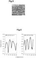
- FIG. 6includes two diagrams illustrating the roughness profiles corresponding to an MC-LIPSS structure.
- FIG 8includes two diagrams illustrating the roughness profiles corresponding to a LIPSS type structure.
- FIG. 10includes two diagrams illustrating the roughness profiles corresponding to an NP structure.
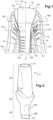
- FIG. 11is a perspective view of an example of a healing screw according to the invention.
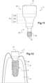
- FIG. 12is a view of the screw shown in Figure 11 placement in an implant fixed in the gum.
- figure 2illustrates an example of a prosthetic pillar according to the invention.
- This pillar 2comprises successively from its distal end 20 and towards its proximal end 21, a distal portion 22 for fixing in an implant, an intermediate portion 23, as well as a proximal portion 24.
- the height of the distal portion 22can be approximately 3 mm, that of the intermediate or sulcular portion 23 can be between 0.7 and 7 mm and that of the proximal portion 24 can be between 4 and 12 mm.
- This proximal portion 24serves to fix a prosthetic element on the pillar while the intermediate portion 23 allows in particular the attachment of the pillar to the epithelial and connective tissues.
- FIG. 3illustrates a pillar 2 of the type of that of the figure 2 placed in an implant 4 which is shown here in section.
- the implant 4is provided with a first blind internal bore 40 comprising on a distal end portion 42 a tapping 41 and a frustoconical proximal end portion 43 for junction with the pillar 2.
- the implanthas a thread 44 on its exterior face.
- the distal portion 22 of the pillarcomprises, from the distal end 20, a first part 220 and a second part 221.
- the second part 221is frustoconical and it is designed to cooperate frictionally with the proximal end portion 43 of the implant when the junction between the pillar and the implant is complete.
- the first part 220has cut sides and is designed to cooperate with a zone of corresponding shape of the implant 4, located between the tapping 41 and the frustoconical end portion 43.
- the pillar 2is fixed in the implant thanks to a screw 5 which penetrates into a bore of the pillar to screw into the thread 41 of the implant, thanks to the thread present on a distal portion of the screw.
- the structure of the surface of the intermediate portion 23is defined so as to promote the attachment of the pillar to the epithelial and connective tissues.
- this intermediate portion 23does not necessarily include three zones whose surface has a structure with a particular function, as stated above.
- first zonewhose surface has a structure promoting the growth of epithelial tissue or a second zone whose surface has a structure favoring the growth of connective tissue with fibers oriented substantially radially.
- the first zonewhich would preferably be provided since it allows the creation of a biological seal around the pillar and therefore allows, therefore, to create a first barrier for bacteria as close as possible to their entry route into the gum.
- This first barrierresults in particular from the fact that the epithelial cells attach to the pillar.
- the presence of the second zonemakes it possible to obtain a connective tissue whose structure is close to that which exists with a natural tooth and which then constitutes an effective support structure for the epithelial attachment.
- the connective tissue fibersdo not wrap around the pillar but extend substantially perpendicularly or radially relative to the pillar.
- the pillar according to the inventionthus makes it possible to reconstruct a cellular environment very close to that existing around a natural tooth.
- the third zone 232when present, further contributes to the effectiveness of the biological seal thus created, by limiting the fixation of dental plaque.
- these structuresare obtained using a femto-laser, that is to say a laser producing ultrashort pulses whose duration is between a few femtoseconds and a few hundred femtoseconds.
- a laser of this typemakes it possible to obtain engravings whose depth is of the order of a hundredth of a micron and which are ordered, that is to say non-random, repetitive, that is to say formed of a pattern repeated on this surface and reproducible. It is thus possible to give each surface the desired function with certainty by appropriately configuring the laser.
- the laser treatmentcreates a layer of titanium oxide which is a biocompatible surface and more resistant to corrosion than the initial constituent material.
- this oxide layerpromotes mineralization.
- FIG. 5An example of an MC-LIPSS surface structure is shown in figure 5 .
- this surfacecomprises micro-columns whose cross section is substantially elliptical which are covered with structures forming undulations (LIPSS structures) whose periodicity is of the same order of magnitude as the laser radiation wavelength or a few hundreds of nanometers.
- LIPSS structuresstructures forming undulations
- two adjacent undulationsare spaced from each other by a distance of between 500 nm and 1000 nm.
- FIG. 6illustrates for two types of titanium, a commercially pure titanium (cp Ti) and for a titanium alloy (of the Ti6A14V type), two graphs illustrating the variation in the height of the roughness of the textured surface (in microns), according to a standardized measurement of the linear surface profile, as a function of the length of the sample (in microns).
- the parameter R a(expressed in microns) is of the order of 0.8 microns for a titanium substrate and of the order of 0.7 microns for a T16A14V substrate.
- the parameter R z(expressed in microns) is of the order of 5.3 for a titanium substrate and of the order of 5.4 for a Ti6A14V support.
- the diameter of each micro-column at its baseis between 600 nm and 800 nm.
- This structurecan extend over the entire surface of the first zone in a uniform manner.
- a specific designcan be produced, consisting of geometric figures distributed in the form of a matrix, these figures being able for example to be a circle, a square or a triangle.
- this matrixtwo adjacent figures are typically spaced a distance between 25 microns and 75 microns. These figures define the space in which the micro-columns are located.
- these non-random geometric figuresare obtained by concentrating the pulse energy of the femto-laser in specific zones defining these geometric shapes.
- Microcolumns covered with LIPSS structuresare obtained in these areas, while the rest of the surface is only covered with LIPSS structures.
- two adjacent undulationsare spaced from each other by a distance of between 500 nm and 1000 nm and have a height of between 100 nm and 500 nm.
- the femto-lasercan be adjusted to concentrate its pulse energy and thus locally vaporize the surface of the first zone.
- the MC-LIPSS structureis generated around this vaporization and over the entire surface.
- these structuresconsist of substantially parallel undulations.
- FIG 8is a view similar to the Figure 6 which comprises two graphs, the first corresponding to pure titanium and the second to a titanium alloy of the Ti6A14V type, illustrating the variation in the height of the surface roughness (in microns) according to a standardized measurement of the linear surface profile, in function of the length (in microns) of the sample.
- R a and R zcan be calculated for this type of structure.
- R ais substantially equal to 0.3 microns for pure titanium and for an alloy of the T16A14V type and that R z is equal to approximately 1.5 microns for pure titanium and 1.4 microns for an alloy of the Ti6A14V type.
- this second zone 231is preferably provided in addition to the first zone 230 so as to constitute an effective support for the epithelial attachment whose formation is favored by the particular texturing of the first zone 230.
- this second zone 231could be provided alone.
- this second zone 231it may be interesting to provide, inside this second zone 231, a surface portion having a different texturing and promoting the formation of epithelial tissue.
- this surface partmay present, for example in an annular manner, a texturing identical to that of the first zone 230 or, in any case, a texturing fulfilling the same function.
- this other differentiated zonemakes it possible to create within it a point of attachment of the epithelial tissue, under the epithelial attachment itself, which creates an additional barrier against the introduction of bacteria.
- Figure 10like the figures 6 And 8 described previously, includes two graphs illustrating the roughness profiles of such texturing, on the one hand for a pure titanium and on the other hand for a titanium alloy of the Ti6A14V type.
- Each of these graphsgives the height of the roughness (in microns) according to a standardized measurement of the linear surface profile, as a function of the length of the sample (in microns).
- R a and R zwere also calculated for this type of texturing.
- R ais substantially equal to 0.3 microns for pure titanium and an alloy of the Ti6A14V type
- R zis equal to approximately 1.6 microns for a pure titanium substrate and to 1.3 microns for a substrate made of titanium alloy of type T16A14V.
- a nano-pillar structure of this typeis obtained using a femtosecond laser and in two steps.
- the surface of the substrateis treated to obtain periodic surface structures (of the LIPSS type) which are in the form of substantially parallel undulations.
- the laser parametersare adjusted so that they generate 192 pulses, with a fluence of 0.3 J/cm 2 .
- the polarization of the laser beamis straight.
- the second stage of surface treatmentis still carried out by a femtosecond laser but with a lower fluence and number of pulses.
- this second stepcan be carried out with a laser configured to generate 47 pulses, with a fluence of 0.10 J/cm 2 .
- the polarization of the laser beamis still straight but its direction is rotated by 90° relative to the direction of the polarization used in the first step of the surface treatment.
- the undulations formed during the first stage of the treatmentare partially destroyed by the second stage of the treatment so as to form these nano-pillars.
- This structurecan extend over the entire surface of the second zone uniformly.
- the surface of the second zonemay include a matrix of pads of substantially square shape, the nano-pillar structure being produced on the surface of each pad.
- the side of the padsis between 20 microns and 45 microns and two adjacent pads are spaced at a distance between 20 microns and 35 microns.
- a textured surface of the LIPSS typealso has the particularity of avoiding the formation of biofilm.
- any type of hydrophobic surfacecan be used for this third zone 232, in order to avoid the formation of biofilm.
- this third zonemakes it possible to reinforce the effects of the first zone and/or the second zone by limiting the presence of bacteria above these two zones. It therefore reinforces the biological barrier function already fulfilled by one or the other of these two zones.
- the inventionalso provides for giving the other surfaces of the pillar particular structures in order to give them reinforced functions.
- the distal portion 22is the portion of the pillar which will be used for its fixation in the implant.
- the structure of the surface of this distal portion 22is chosen so as to improve the tightness of the connection between the pillar 2 and the implant.
- This structurecan also be obtained thanks to the action of a femtosecond laser. It may in particular be a structure having a micrometric grip aimed at increasing the mechanical retention of the connection (for example conical) between the pillar and the implant and at improving the seal at the interface between the two parts.
- Improving the tightness of the connection between the abutment and the implantalso helps avoid contamination by pathogenic bacteria present in the mouth, which can lead to bone loss.
- This engravingcan consist of a 2D code, of the data Matrix type, allowing the unique identification of the pillar.
- proximal portion 24 of the pillaris intended for fixing a prosthesis.
- this proximal portionhas a particular structure, in order to improve the fixation of the prosthesis on the pillar.
- this structurecan be of greater roughness than the raw machined structure in order to increase the retention of the sealing or bonding of the prosthesis to the abutment.
- the inventionproposes to give the surface of each part of the pillar a specific structure so as to give it a particular function or to improve the function already fulfilled.
- three portionscan also be defined from its distal end 30 to its proximal end 31.
- the screw 3comprises a distal portion 32 for fixing in the implant 4, this portion comprising a thread 35.
- This distal portion 32comprises for example a conical zone whose height is approximately 2 mm and a thread whose height is between 1 and 3 mm, for a diameter between 1.2 and 2 mm.
- an intermediate portion 33In the direction of its proximal end, there extends an intermediate portion 33 whose height is between 0.7 and 7 mm and which is notably equal to 3 mm. It is extended by a proximal portion 34 whose height is between 1 and 5 mm and which is in particular equal to 3 mm. The latter corresponds to the part of the screw located partly outside the gum when the healing screw is screwed into the implant, itself being fixed in the jaw of a patient.
- a first zone 330framed by a second zone 331 and a third zone 332.
- the second zone 331extends between the first zone 330 and the distal portion 32 of the screw, while the third zone extends between the first zone and the proximal portion 34 of the screw.
- the surface of each of these zonesis chosen to present a particular function.
- the structure of the surface of the first zone 330will be chosen to promote the growth of the epithelial tissue. As described previously, this structure could in particular be of the MC-LIPSS type. This structure has already been written for a pillar and will not be described in detail again.
- the structure of the surface of the second zone 331will be chosen so as to promote the growth of the connective tissue, with fibers oriented substantially radially.
- This structurecould in particular be of the LIPSS type, as described previously for a pillar.
- the structure of the surface of the third zone 332will be chosen so that this surface is hydrophobic and we again refer to the examples given previously for a pillar according to the invention.
- the first zone 330which has a functionalized surface so as to create a barrier for bacteria which is furthest from the bone.
- This barrier functionis of course reinforced when the second zone 331 is itself functionalized in accordance with the invention.
- the third zone 332when it is hydrophobic, makes it possible to avoid the fixation of dental plaque, which further reinforces the barrier function provided by the first zone 330 and/or the second zone 331.
- the function of this third zone 332is therefore complementary to that of the first zone and/or the second zone.
- annular partscan be provided whose surface has a structure having the same function as the first zone, that is to say to promote the growth of epithelial tissue. This makes it possible to create, inside the second zone, epithelial attachments in addition to that already created at the level of the first zone 330.
- FIG. 12shows screw 3 in implant 4, itself fixed in bone 12.
- the materials constituting a pillar or a healing screw according to the inventionare typically based on titanium, whether commercially pure titanium or a titanium alloy.
- other biocompatible materialscan be considered such as other metal alloys (titanium-nobium, titate-zireone, cobalt-chromium), ceramics (zirconia) or plastics (PEEK, polyethylene).
Landscapes
- Health & Medical Sciences (AREA)
- Oral & Maxillofacial Surgery (AREA)
- Orthopedic Medicine & Surgery (AREA)
- Dentistry (AREA)
- Epidemiology (AREA)
- Life Sciences & Earth Sciences (AREA)
- Animal Behavior & Ethology (AREA)
- General Health & Medical Sciences (AREA)
- Public Health (AREA)
- Veterinary Medicine (AREA)
- Dental Prosthetics (AREA)
- Prostheses (AREA)
Description
Translated fromFrenchLa présente invention concerne le domaine technique des implants et plus particulièrement des pièces utilisées en association avec ces implants, de manière temporaire ou définitive.The present invention relates to the technical field of implants and more particularly to the parts used in association with these implants, temporarily or permanently.
On rappelle qu'un implant dentaire comporte un corps d'ancrage fileté qui est mis en place par vissage dans une cavité de la mâchoire, notamment réalisée par un forage. Est mise ensuite en place une vis de cicatrisation.It is recalled that a dental implant comprises a threaded anchoring body which is placed by screwing in a cavity of the jaw, in particular made by drilling. A healing screw is then placed.
Ultérieurement, après intégration de l'implant dans l'os, la vis de cicatrisation est retirée et un pilier prothétique est fixé dans l'implant. Ce pilier compense l'épaisseur de la muqueuse et permet la fixation d'un élément prothétique proprement dit.Subsequently, after integration of the implant into the bone, the healing screw is removed and a prosthetic abutment is fixed in the implant. This pillar compensates for the thickness of the mucosa and allows the fixation of a prosthetic element itself.
Tous les éléments sont réalisés en un matériau biocompatible, par exemple en Titane ou en un alliage de Titane.All elements are made of a biocompatible material, for example titanium or a titanium alloy.
On peut également utiliser des implants solidaires d'un pilier prothétique, tels que par exemple décrits dans le document
Ces implants ont été perfectionnés au cours des années pour améliorer leur intégration osseuse, notamment en gravant la surface du corps d'ancrage.These implants have been perfected over the years to improve their bone integration, in particular by engraving the surface of the anchoring body.
L'invention part du constat qu'une bonne intégration osseuse de l'implant dans les mois suivant sa mise en place n'évite pas des problèmes ultérieurs de descellement. Ceci est dû à une dégradation de l'os péri-implantaire, notamment du fait de la présence de bactéries qui s'introduisent entre l'implant et les tissus épithélial et conjonctif.The invention is based on the observation that good bone integration of the implant in the months following its installation does not avoid subsequent loosening problems. This is due to degradation of the peri-implant bone, in particular due to the presence of bacteria which are introduced between the implant and the epithelial and connective tissues.
L'importance du système d'attache des structures muqueuses à la périphérie de la dent va être rappelée en référence à la
Cette figure est une vue en coupe de la gencive permettant de comparer la situation d'une dent naturelle 10 (côté droit de la figure) à celle d'un implant 11 ancré dans l'os (côté gauche de la figure) .This figure is a sectional view of the gum allowing the situation of a natural tooth 10 (right side of the figure) to be compared to that of an
L'implant 11 comporte un corps d'ancrage 110 fileté. Un pilier prothétique 111 est solidaire du corps d'ancrage.The
Un élément prothétique 112 est par ailleurs fixé sur le pilier 111. La dent 10 comporte une racine 100 et une couronne 101.A
Le corps d'ancrage 110 de l'implant comme la racine 100 de la dent sont insérés dans l'os 12 de la mâchoire.The anchoring
Dans le cas d'une dent naturelle, la racine est fixée à l'os par l'intermédiaire d'une couche de cément 13 qui s'étend jusqu'à la couronne 101 et par le ligament alvéolo-dentaire 14.In the case of a natural tooth, the root is fixed to the bone via a layer of
Bien entendu, la couche de cément qui recouvre la racine de la dent n'est pas présente sur l'implant. C'est également le cas pour le ligament alvéolo-dentaire.Of course, the cementum layer that covers the root of the tooth is not present on the implant. This is also the case for the alveolar-dental ligament.
L'os 12 est entouré par une couche de tissu conjonctif 15, elle-même recouverte d'une couche d'épithélium 16.
La
Pour une dent naturelle, on distingue deux types de fibres : les fibres 170 qui s'accrochent sur l'os 12 et qui sont orientées selon un angle inférieur à 45° environ par rapport à l'axe X-X' de la dent ou de l'implant et les fibres 171 qui s'étendent sensiblement radialement et qui s'accrochent sur la couche de cément présente sur la dent, au-delà de l'os 12.For a natural tooth, there are two types of fibers:
On comprend donc que ces fibres radiales 171 ne sont pas présentes sur l'implant puisque celui-ci ne comporte pas de cément.We therefore understand that these
La
On sait que, pour une dent, ces fibres 171 orientées sensiblement perpendiculairement à l'axe de la dent permettent d'assurer une barrière protectrice étanche, en combinaison avec l'épithélium de jonction 160 qui vient s'insérer à l'interface entre la racine 100 et sa couronne 101.We know that, for a tooth, these
Pour un implant, l'épithélium de jonction 161 est bien présent mais son accroche sur le pilier 111 de l'implant n'est pas très résistante et ce d'autant plus en l'absence de fibres orientées sensiblement perpendiculairement à l'axe de l'implant.For an implant, the
Ainsi, la cicatrisation autour d'un implant conduit à une structure des tissus conjonctifs qui est différente de celle observée avec une dent naturelle.Thus, healing around an implant leads to a connective tissue structure that is different from that observed with a natural tooth.
Ceci conduit également à des inconvénients avant la mise en place sur l'implant du pilier implantaire, c'est-à-dire en présence d'une vis de cicatrisation. En effet, le même phénomène se produit avec la vis de cicatrisation, aucune fibre s'étendant sensiblement radialement ne se créant au niveau de cette vis de cicatrisation.This also leads to disadvantages before the implant abutment is placed on the implant, that is to say in the presence of a healing screw. Indeed, the same phenomenon occurs with the healing screw, no fiber extending substantially radially being created at the level of this healing screw.
On peut alors observer, lors de la dépose de cette vis, une contraction des fibres élastiques qui conduit à la réduction de l'orifice d'accès à la connexion avec l'implant et qui pose donc problème lors de la mise en place du pilier implantaire.We can then observe, when removing this screw, a contraction of the elastic fibers which leads to the reduction of the access orifice to the connection with the implant and which therefore poses a problem when installing the abutment. implant.
L'objectif principal de l'invention est de réduire les risques de descellement d'un implant au cours du temps en évitant l'introduction de bactéries.The main objective of the invention is to reduce the risks of loosening of an implant over time by avoiding the introduction of bacteria.
Toutes les solutions connues concernent l'implant et s'attachent à différencier la surface extérieure de celui-ci en prévoyant des zones de structures différentes.All known solutions concern the implant and focus on differentiating the external surface thereof by providing zones of different structures.
Ainsi, le document
Le document
De même, le document
Au contraire, l'invention part du constat que les piliers prothétiques comme les vis de cicatrisation sont jusqu'ici utilisés uniquement pour leur fonction mécanique et qu'il est possible et souhaitable de leur conférer d'autres fonctions, sans que leur conception ne soit modifiée, en termes de structure générale ou de dimensionnement.On the contrary, the invention is based on the observation that prosthetic pillars like healing screws are until now used solely for their mechanical function and that it is possible and desirable to give them other functions, without their design being altered. modified, in terms of general structure or dimensioning.
Le document
L'invention propose de favoriser la re-création autour du pilier prothétique ou d'une vis de cicatrisation d'un tissu épithélial et/ou conjonctif qui sont les plus proches possible du tissu épithélial et/ou conjonctif présents autour d'une dent naturelle.The invention proposes to promote the re-creation around the prosthetic pillar or a healing screw of an epithelial and/or connective tissue which are as close as possible to the epithelial and/or connective tissue present around a natural tooth .
Ceci permet de recréer autour du pilier et/ou de la vis de cicatrisation une barrière contre l'introduction de bactéries qui assurera la protection de l'os péri-implantaire. Les risques de descellement de l'implant seront donc considérablement réduits.This makes it possible to recreate a barrier around the abutment and/or the healing abutment against the introduction of bacteria which will ensure the protection of the peri-implant bone. The risks of loosening of the implant will therefore be considerably reduced.
L'invention concerne donc une pièce destinée à être utilisée en association avec un implant dentaire, qui est lui-même destiné à être fixé dans une mâchoire, cette pièce comportant successivement depuis son extrémité distale et en direction de son extrémité proximale, une portion distale de fixation dans l'implant, une portion intermédiaire d'accroche aux tissus épithélial et/ou conjonctif et une portion proximale, cette pièce comportant également au moins deux zones dont les surfaces présentent une structure différente l'une de l'autre, la structure de la surface d'au moins l'une de ces deux zones, située dans la portion intermédiaire, étant ordonnée et répétitive, adaptée à la croissance du tissu épithélial et/ou du tissu conjonctif et présentant des gravures formant des ondulations et dont la profondeur est inférieure à 0,5 microns et des micro-colonnes recouvertes par les gravures formant des ondulations, cette structure favorisant la croissance du tissu épithélial ainsi que sa fixation sur la pièce.The invention therefore relates to a part intended to be used in association with a dental implant, which is itself intended to be fixed in a jaw, this part comprising successively from its distal end and towards its proximal end, a distal portion fixing in the implant, an intermediate portion for attachment to the epithelial and/or connective tissues and a proximal portion, this part also comprising at least two zones whose surfaces have a structure different from each other, the structure of the surface of at least one of these two zones, located in the intermediate portion, being ordered and repetitive, adapted to the growth of epithelial tissue and/or connective tissue and having engravings forming undulations and whose depth is less than 0.5 microns and micro-columns covered by the engravings forming undulations, this structure promoting the growth of the epithelial tissue as well as its attachment to the part.
Cette pièce peut être un pilier prothétique, solidaire de l'implant ou destiné à être fixé dans celui-ci, ou une vis de cicatrisation.This part can be a prosthetic pillar, attached to the implant or intended to be fixed in it, or a healing screw.
Les cellules qui se développent sur la surface de cette première zone vont orienter leur croissance avec un cytosquelette en forme d'étoile, spécifique des cellules épithéliales, ce qui conduit à la formation des fibres du tissu épithélial, lesquelles s'accrochent sur la surface du pilier.The cells which develop on the surface of this first zone will direct their growth with a star-shaped cytoskeleton, specific to epithelial cells, which leads to the formation of epithelial tissue fibers, which attach to the surface of the pillar.
Ainsi, la pièce permet de créer une première barrière pour les bactéries qui sera la plus éloignée de l'os dans lequel l'implant est ancré.Thus, the part makes it possible to create a first barrier for bacteria which will be furthest from the bone in which the implant is anchored.
Par ailleurs, il est également préféré qu'en complément de cette première zone, la pièce comporte une deuxième zone dont la surface présente une structure différente de celle de la première zone et qui, quant à elle, va favoriser la croissance du tissu conjonctif et sa fixation sur la pièce, cette deuxième zone étant également située dans la portion intermédiaire de la pièce, entre la portion distale et la première zone de la portion intermédiaire.Furthermore, it is also preferred that in addition to this first zone, the part includes a second zone whose surface has a structure different from that of the first zone and which, for its part, will promote the growth of the connective tissue and its attachment to the part, this second zone also being located in the intermediate portion of the part, between the distal portion and the first zone of the intermediate portion.
Les cellules qui se développent sur la surface de cette deuxième zone vont orienter leur croissance avec un cytosquelette en forme allongée, spécifique aux cellules fibroblastiques à l'origine du tissu conjonctif, lequel comporte des fibres orientées sensiblement radialement ou perpendiculairement par rapport à cette surface.The cells which develop on the surface of this second zone will direct their growth with a cytoskeleton in elongated shape, specific to fibroblastic cells at the origin of connective tissue, which includes fibers oriented substantially radially or perpendicularly to this surface.
Ces fibres sensiblement radiales formées dans le tissu conjonctif forment ainsi une zone de renforcement pour l'attache épithéliale, comme cela est constaté pour une dent naturelle.These substantially radial fibers formed in the connective tissue thus form a reinforcing zone for the epithelial attachment, as is observed for a natural tooth.
On peut également prévoir, à l'intérieur de cette deuxième zone, au moins une autre zone espacée de la première zone mais présentant une surface dont la structure a une fonction similaire à celle de la première zone. Cette autre zone présente donc une structure différente de celle de la deuxième zone.It is also possible to provide, inside this second zone, at least one other zone spaced from the first zone but having a surface whose structure has a function similar to that of the first zone. This other zone therefore has a different structure from that of the second zone.
Cette autre zone permet de créer, à l'intérieur d'une région du tissu conjonctif en regard de cette deuxième zone, un point d'attache du type épithélial, entre l'attache épithéliale proprement dite et l'os.This other zone makes it possible to create, within a region of the connective tissue opposite this second zone, an epithelial type attachment point, between the epithelial attachment itself and the bone.
La structure de ladite éventuelle autre zone, prévue à l'intérieur de la deuxième zone, peut notamment comporter des micro-colonnes recouvertes par lesdites gravures formant des ondulations.The structure of said possible other zone, provided inside the second zone, may in particular include micro-columns covered by said engravings forming undulations.
Ainsi, l'invention permet de diriger et contrôler les attaches des tissus épithélial et conjonctif sur cette pièce, qu'elle soit un pilier implantaire ou une vis de cicatrisation. Ceci permet de créer un joint biologique autour de l'implant, similaire à celui qui existe pour une dent naturelle, lequel protège l'os.Thus, the invention makes it possible to direct and control the attachments of the epithelial and connective tissues to this part, whether it is an implant pillar or a healing screw. This creates a biological seal around the implant, similar to that which exists for a natural tooth, which protects the bone.
Dans d'autres modes de mise en oeuvre avantageux, on a de plus recours à l'une ou à l'autre des dispositions suivantes :
- la pièce comporte dans sa portion intermédiaire, une troisième zone dont la surface présente une structure différente de celle de la première zone, cette surface étant texturée pour limiter la fixation de la plaque dentaire, cette troisième zone étant située entre ladite première zone et la portion proximale.
- the part comprises in its intermediate portion, a third zone whose surface has a structure different from that of the first zone, this surface being textured to limit the fixation of the dental plaque, this third zone being located between said first zone and the portion proximal.
La surface de la troisième zone est hydrophobe.
- la structure de ladite troisième zone peut comporter des nano-piliers.
- Pour une pièce se présentant sous la forme d'un pilier destiné à être fixé dans un implant, ce pilier comporte dans sa portion distale une surface texturée pour assurer la rétention mécanique ou l'étanchéité entre le pilier et l'implant.
- Lorsque la pièce est un pilier prothétique, sa portion proximale comporte une zone de fixation d'un élément prothétique, s'étendant depuis l'extrémité proximale du pilier, cette zone présente une surface dont la structure est texturée pour améliorer la fixation entre le pilier et l'élément prothétique.
- the structure of said third zone may include nano-pillars.
- For a part in the form of a pillar intended to be fixed in an implant, this pillar comprises in its distal portion a textured surface to ensure mechanical retention or sealing between the pillar and the implant.
- When the part is a prosthetic pillar, its proximal portion comprises a zone for fixing a prosthetic element, extending from the proximal end of the pillar, this zone has a surface whose structure is textured to improve the fixation between the pillar and the prosthetic element.
La
La
La
La
La
La
La
La
La
Les éléments communs aux différentes figures seront affectés des mêmes références.The elements common to the different figures will be assigned the same references.
Il est tout d'abord fait référence à la
Ce pilier 2 comporte successivement depuis son extrémité distale 20 et en direction de son extrémité proximale 21, une portion distale 22 de fixation dans un implant, une portion intermédiaire 23, ainsi qu'une portion proximale 24.This
La hauteur de la portion distale 22 peut être d'environ 3 mm, celle de la portion intermédiaire ou sulculaire 23 peut être comprise entre 0,7 et 7 mm et celle de la portion proximale 24 peut être comprise entre 4 et 12 mm.The height of the
Cette portion proximale 24 sert à la fixation d'un élément prothétique sur le pilier tandis que la portion intermédiaire 23 permet notamment l'accroche du pilier aux tissus épithélial et conjonctif.This
La
L'implant 4 est muni d'un premier alésage interne borgne 40 comportant sur une portion d'extrémité distale 42 un taraudage 41 et une portion d'extrémité proximale tronconique 43 de jonction avec le pilier 2.The
L'implant comporte un filetage 44 sur sa face extérieure.The implant has a
La portion distale 22 du pilier comporte depuis l'extrémité distale 20, une première partie 220 et une deuxième partie 221.The
De façon connue, la deuxième partie 221 est tronconique et elle est conçue pour coopérer à frottement avec la portion d'extrémité proximale 43 de l'implant lorsque la jonction entre le pilier et l'implant est complète.In known manner, the
Par ailleurs, la première partie 220 comporte des pans coupés et elle est conçue pour coopérer avec une zone de forme correspondante de l'implant 4, située entre le taraudage 41 et la portion d'extrémité tronconique 43.Furthermore, the
Enfin, le pilier 2 est fixé dans l'implant grâce à une vis 5 qui pénètre dans un alésage du pilier pour se visser dans le taraudage 41 de l'implant, grâce au filetage présent sur une portion distale de la vis.Finally, the
Dans le cadre de l'invention, la structure de la surface de la portion intermédiaire 23 est définie de façon à favoriser l'accroche du pilier aux tissus épithélial et conjonctif.In the context of the invention, the structure of the surface of the
Il est maintenant fait référence à la
En pratique, cette portion intermédiaire peut être décomposée en trois zones :
une première zone 230 dont la surface présente une structure destinée à favoriser la croissance du tissu épithélial ainsi que sa fixation sur le pilier 2, cette premièrezone 230 étant encadrée par- une deuxième
zone 231 qui s'étend entre la première zone etla portion distale 22 du pilier, cette deuxième zone présentant une surface dont la structure favorise la croissance du tissu conjonctif, avec des fibres orientées sensiblement radialement, ainsi que sa fixation sur le pilier 2, et par
- une troisième
zone 232 qui s'étend entre cette première zone etla portion proximale 24 du pilier, la surface de cette troisième zone étant hydrophobe, de façon à limiter la fixation de la plaque dentaire.
- a
first zone 230 whose surface has a structure intended to promote the growth of the epithelial tissue as well as its attachment to thepillar 2, thisfirst zone 230 being framed by - a
second zone 231 which extends between the first zone and thedistal portion 22 of the pillar, this second zone having a surface whose structure promotes the growth of connective tissue, with fibers oriented substantially radially, as well as its fixation on thepillar 2, and by
- a
third zone 232 which extends between this first zone and theproximal portion 24 of the pillar, the surface of this third zone being hydrophobic, so as to limit the fixation of the dental plaque.
Il convient ici de noter que cette portion intermédiaire 23 ne comporte pas nécessairement trois zones dont la surface présente une structure avec une fonction particulière, telle qu'énoncée ci-dessus.It should be noted here that this
En pratique, il convient cependant que soit présente au moins une première zone dont la surface présente une structure favorisant la croissance du tissu épithélial ou une deuxième zone dont la surface présente une structure favorisant la croissance du tissu conjonctif avec des fibres orientées sensiblement radialement.In practice, however, it is appropriate that there be present at least a first zone whose surface has a structure promoting the growth of epithelial tissue or a second zone whose surface has a structure favoring the growth of connective tissue with fibers oriented substantially radially.
Si une seule de ces zones devait être présente sur le pilier, c'est la première zone qui serait prévue de préférence puisqu'elle permet la création d'un joint biologique autour du pilier et donc permet, de ce fait, de créer une première barrière pour les bactéries au plus près de leur voie d'entrée dans la gencive.If only one of these zones were to be present on the pillar, it is the first zone which would preferably be provided since it allows the creation of a biological seal around the pillar and therefore allows, therefore, to create a first barrier for bacteria as close as possible to their entry route into the gum.
Cette première barrière résulte notamment du fait que les cellules épithéliales se fixent sur le pilier.This first barrier results in particular from the fact that the epithelial cells attach to the pillar.
Bien entendu, une efficacité encore plus grande est obtenue lorsque les première et deuxième zones sont présentes sur le pilier. En effet, la présence de la deuxième zone permet d'obtenir un tissu conjonctif dont la structure est proche de celui qui existe avec une dent naturelle et qui constitue alors une structure de soutien efficace pour l'attache épithéliale.Of course, even greater efficiency is achieved when the first and second zones are present on the pillar. Indeed, the presence of the second zone makes it possible to obtain a connective tissue whose structure is close to that which exists with a natural tooth and which then constitutes an effective support structure for the epithelial attachment.
Dans cette deuxième zone, les fibres du tissu conjonctif ne s'enroulent pas autour du pilier mais s'étendent sensiblement perpendiculairement ou radialement par rapport au pilier.In this second zone, the connective tissue fibers do not wrap around the pillar but extend substantially perpendicularly or radially relative to the pillar.
Le pilier selon l'invention permet ainsi de reconstituer un environnement cellulaire très proche de celui existant autour d'une dent naturelle.The pillar according to the invention thus makes it possible to reconstruct a cellular environment very close to that existing around a natural tooth.
Enfin, la troisième zone 232, lorsqu'elle est présente, contribue encore à l'efficacité du joint biologique ainsi créé, en limitant la fixation de la plaque dentaire.Finally, the
En référence aux
De façon générale, ces structures sont obtenues grâce à un femto-laser, c'est-à-dire un laser produisant des impulsions ultracourtes dont la durée est comprise entre quelques femtosecondes et quelques centaines de femtosecondes.Generally speaking, these structures are obtained using a femto-laser, that is to say a laser producing ultrashort pulses whose duration is between a few femtoseconds and a few hundred femtoseconds.
Elles subissent ensuite une opération de nettoyage.They then undergo a cleaning operation.
Un laser de ce type permet d'obtenir des gravures dont la profondeur est de l'ordre du centième de micron et qui sont ordonnées c'est-à-dire non aléatoires, répétitives c'est-à-dire formées d'un motif répété sur cette surface et reproductibles. Il est ainsi possible de conférer à chaque surface et avec certitude la fonction souhaitée en paramétrant de manière appropriée le laser.A laser of this type makes it possible to obtain engravings whose depth is of the order of a hundredth of a micron and which are ordered, that is to say non-random, repetitive, that is to say formed of a pattern repeated on this surface and reproducible. It is thus possible to give each surface the desired function with certainty by appropriately configuring the laser.
De plus, le traitement par un laser de la surface du pilier, effectué avec de l'air, oxyde cette surface. Ceci est notamment dû au niveau de température atteint en surface pendant ce traitement.In addition, laser treatment of the surface of the pillar, carried out with air, oxidizes this surface. This is particularly due to the temperature level reached on the surface during this treatment.
Ainsi, lorsque le pilier est réalisé en titane ou en un alliage de titane, le traitement par laser crée une couche d'oxyde de titane qui est une surface biocompatible et plus résistante à la corrosion que le matériau constitutif de départ. De plus, cette couche d'oxyde favorise la minéralisation.Thus, when the pillar is made of titanium or a titanium alloy, the laser treatment creates a layer of titanium oxide which is a biocompatible surface and more resistant to corrosion than the initial constituent material. In addition, this oxide layer promotes mineralization.
Vont maintenant être décrites des exemples de structures pour les surfaces de chacune des trois zones 230 à 232.Examples of structures for the surfaces of each of the three
Au niveau de la première zone 230, on pourra prévoir de texturer par laser femtoseconde le pilier de façon à obtenir des micro-colonnes recouvertes de structures de surface périodiques formant des ondulations (ou encore LIPSS, c'est-à-dire Laser-Induced Periodic Surface Structures, dans la terminologie anglaise). Cette structure particulière est désignée par le terme MC-LIPSS dans la terminologie anglaise.At the level of the
Un exemple d'une structure de surface MC-LIPSS est illustré à la
La
Les paramètres de rugosité d'une telle surface ont été mesurés. On rappelle que le paramètre Ra donne la rugosité moyenne arithmétique du profil, tandis que le paramètre Rz donne la rugosité maximale du profil.The roughness parameters of such a surface were measured. We recall that the parameter Ra gives the arithmetic average roughness of the profile, while the parameter Rz gives the maximum roughness of the profile.
Le paramètre Ra (exprimé en microns) est de l'ordre de 0,8 microns pour un substrat en titane et de l'ordre de 0,7 microns pour un substrat en T16A14V.The parameter Ra (expressed in microns) is of the order of 0.8 microns for a titanium substrate and of the order of 0.7 microns for a T16A14V substrate.
Par ailleurs le paramètre Rz (exprimé en microns) est de l'ordre de 5,3 pour un substrat en titane et de l'ordre de 5,4 pour un support en Ti6A14V.Furthermore, the parameter Rz (expressed in microns) is of the order of 5.3 for a titanium substrate and of the order of 5.4 for a Ti6A14V support.
En pratique, on obtient une texturation avec des micro-colonnes en traitant la surface avec un femto-laser. Sous l'effet du femto-laser, dans un premier temps, apparaissent les structures de surface périodique se présentant sous la forme d'ondulations sensiblement parallèles (LIPSS) et, grâce à l'énergie d'impulsion du femto-laser, les micro-colonnes apparaissent dans un deuxième temps. Elles sont donc recouvertes de structures LIPSS.In practice, texturing is obtained with micro-columns by treating the surface with a femto-laser. Under the effect of the femto-laser, initially, periodic surface structures appear in the form of substantially parallel undulations (LIPSS) and, thanks to the pulse energy of the femto-laser, the micro -columns appear in a second step. They are therefore covered with LIPSS structures.
De façon préférée, le diamètre de chaque micro-colonne à sa base est compris entre 600 nm et 800 nm.Preferably, the diameter of each micro-column at its base is between 600 nm and 800 nm.
Cette structure peut s'étendre sur toute la surface de la première zone de manière uniforme.This structure can extend over the entire surface of the first zone in a uniform manner.
Cependant, l'invention n'est pas limitée à ce mode de réalisation.However, the invention is not limited to this embodiment.
Ainsi, sur la surface de la première zone peut être réalisé un design spécifique, constitué de figures géométriques réparties sous la forme d'une matrice, ces figures pouvant par exemple être un cercle, un carré ou un triangle. Dans cette matrice, deux figures adjacentes sont typiquement espacées d'une distance comprise entre 25 microns et 75 microns. Ces figures définissent l'espace dans lequel se trouvent les micro-colonnes.Thus, on the surface of the first zone a specific design can be produced, consisting of geometric figures distributed in the form of a matrix, these figures being able for example to be a circle, a square or a triangle. In this matrix, two adjacent figures are typically spaced a distance between 25 microns and 75 microns. These figures define the space in which the micro-columns are located.
En pratique, ces figures géométriques non-aléatoires sont obtenues en concentrant l'énergie d'impulsion du femto-laser dans des zones spécifiques définissant ces formes géométriques.In practice, these non-random geometric figures are obtained by concentrating the pulse energy of the femto-laser in specific zones defining these geometric shapes.
Les micro-colonnes recouvertes de structures LIPSS sont obtenues dans ces zones, tandis que le reste de la surface est seulement recouvert de structures LIPSS.Microcolumns covered with LIPSS structures are obtained in these areas, while the rest of the surface is only covered with LIPSS structures.
L'ensemble de la surface est donc recouvert de structures formant des ondulations du type LIPSS.The entire surface is therefore covered with structures forming LIPSS type undulations.
Ainsi, ces ondulations recouvrent l'ensemble de la surface de la première zone, que celle-ci comporte ou non des micro-colonnes sur toute sa surface.Thus, these undulations cover the entire surface of the first zone, whether or not it includes micro-columns over its entire surface.
De façon préférée, deux ondulations adjacentes sont espacées l'une de l'autre d'une distance comprise entre 500 nm et 1000 nm et présentent une hauteur comprise entre 100 nm et 500 nm.Preferably, two adjacent undulations are spaced from each other by a distance of between 500 nm and 1000 nm and have a height of between 100 nm and 500 nm.
Dans une variante, on peut prévoir de régler le femto-laser pour concentrer son énergie d'impulsion et ainsi vaporiser localement la surface de la première zone. La structure MC-LIPSS est générée autour de cette vaporisation et ce, sur toute la surface.Alternatively, the femto-laser can be adjusted to concentrate its pulse energy and thus locally vaporize the surface of the first zone. The MC-LIPSS structure is generated around this vaporization and over the entire surface.
Lorsque la structure MC-LIPSS est réalisée selon une matrice, la surface de la première zone qui n'est ni vaporisée, ni recouverte d'une structure MC-LIPSS, est recouverte de structures LIPSS.When the MC-LIPSS structure is produced according to a matrix, the surface of the first zone which is neither vaporized nor covered with an MC-LIPSS structure, is covered with LIPSS structures.
On a constaté que ce type de structure favorisait la différenciation et la croissance du tissu épithélial et c'est pourquoi il est prévu dans la première zone 230 de la portion intermédiaire 23.It has been observed that this type of structure favors the differentiation and growth of epithelial tissue and this is why it is provided in the
En ce qui concerne maintenant la deuxième zone 231, on pourra prévoir de texturer sa surface afin que celle-ci présente une structure de type LIPSS (Laser-Induced Periodic Surface Structures dans la terminologie anglaise), c'est-à-dire une structure de surface périodique obtenu par un traitement laser.With regard now to the
Comme indiqué plus haut, ces structures consistent en des ondulations sensiblement parallèles.As indicated above, these structures consist of substantially parallel undulations.
Une structure de ce type est illustrée à la
La
Comme précédemment, peuvent être calculés les paramètres de rugosité Ra et Rz pour ce type de structure. On peut ainsi mesurer que Ra est sensiblement égal à 0,3 microns pour du titane pur et pour un alliage du type T16A14V et que Rz est égal à environ 1,5 microns pour du titane pur et 1,4 microns pour un alliage du type Ti6A14V.As previously, the roughness parameters Ra and Rz can be calculated for this type of structure. We can thus measure that Ra is substantially equal to 0.3 microns for pure titanium and for an alloy of the T16A14V type and that Rz is equal to approximately 1.5 microns for pure titanium and 1.4 microns for an alloy of the Ti6A14V type.
Dans le cadre de l'invention, on retiendra une structure du type LIPSS dont les ondulations sont espacées d'environ 500 nm et, de façon plus générale, dont la périodicité est comprise entre 500 nm et 1000 nm, ces ondulations présentant une hauteur comprise entre 100 nm et 500 nm.In the context of the invention, we will retain a structure of the LIPSS type whose undulations are spaced approximately 500 nm apart and, more generally, whose periodicity is between 500 nm and 1000 nm, these undulations having a height comprised between 100 nm and 500 nm.
On a pu constater qu'une structure de ce type permet de favoriser la croissance du tissu conjonctif avec des fibres orientées sensiblement radialement.It has been observed that a structure of this type makes it possible to promote the growth of connective tissue with fibers oriented substantially radially.
Comme expliqué précédemment, cette deuxième zone 231 est, de préférence, prévue en complément de la première zone 230 de façon à constituer un support efficace pour l'attache épithéliale dont la formation est favorisée par la texturation particulière de la première zone 230. Cependant, cette deuxième zone 231 pourrait être prévue seule.As explained previously, this
À cet égard, il peut être intéressant de prévoir, à l'intérieur de cette deuxième zone 231, une partie de surface présentant une texturation différente et favorisant la formation du tissu épithélial.In this regard, it may be interesting to provide, inside this
Ainsi, cette partie de surface pourra présenter, par exemple de façon annulaire, une texturation identique à celle de la première zone 230 ou, en tout état de cause, une texturation remplissant la même fonction.Thus, this surface part may present, for example in an annular manner, a texturing identical to that of the
La présence de cette autre zone différenciée à l'intérieur de la deuxième zone permet de créer à l'intérieur de celle-ci un point d'attache du tissu épithélial, sous l'attache épithéliale elle-même, ce qui créé une barrière supplémentaire contre l'introduction des bactéries.The presence of this other differentiated zone inside the second zone makes it possible to create within it a point of attachment of the epithelial tissue, under the epithelial attachment itself, which creates an additional barrier against the introduction of bacteria.
Il convient de souligner que les structures de surface décrites en référence aux
En ce qui concerne maintenant la troisième zone 232 de la portion intermédiaire 23, on pourra prévoir sur sa surface une texturation du type nano-piliers (ou NP dans la terminologie anglaise).With regard now to the
Cette structure est illustrée par la
Par ailleurs, la
Chacun de ces graphes donnent la hauteur des rugosités (en microns) selon une mesure normée du profil linéaire de surface, en fonction de la longueur de l'échantillon (en microns).Each of these graphs gives the height of the roughness (in microns) according to a standardized measurement of the linear surface profile, as a function of the length of the sample (in microns).
Les paramètres de rugosité Ra et Rz ont également été calculés pour ce type de texturation. Ainsi, Ra est sensiblement égal à 0,3 microns pour un titane pur et un alliage du type Ti6A14V, tandis que Rz est égal à environ 1,6 microns pour un substrat en titane pur et à 1,3 microns pour un substrat en alliage de titane du type T16A14V.The roughness parameters Ra and Rz were also calculated for this type of texturing. Thus, Ra is substantially equal to 0.3 microns for pure titanium and an alloy of the Ti6A14V type, while Rz is equal to approximately 1.6 microns for a pure titanium substrate and to 1.3 microns for a substrate made of titanium alloy of type T16A14V.
Une structure en nano-piliers de ce type est obtenue grâce à un laser femtoseconde et en deux étapes.A nano-pillar structure of this type is obtained using a femtosecond laser and in two steps.
Dans une première étape, la surface du substrat est traitée pour obtenir des structures de surface périodique (du type LIPSS) qui se présentent sous la forme d'ondulations sensiblement parallèles.In a first step, the surface of the substrate is treated to obtain periodic surface structures (of the LIPSS type) which are in the form of substantially parallel undulations.
Dans cette première étape, les paramètres du laser sont réglés pour qu'ils génèrent 192 impulsions, avec une fluence de 0,3 J/cm2. Dans cette première étape, la polarisation du faisceau laser est droite.In this first step, the laser parameters are adjusted so that they generate 192 pulses, with a fluence of 0.3 J/cm2 . In this first step, the polarization of the laser beam is straight.
La deuxième étape du traitement de la surface est toujours réalisée par un laser femtoseconde mais avec une fluence et un nombre d'impulsions inférieurs. Ainsi, cette deuxième étape peut être réalisée avec un laser paramétré pour générer 47 impulsions, avec une fluence de 0,10 J/cm2. Dans cette deuxième étape, la polarisation du faisceau laser est toujours droite mais sa direction est tournée de 90° par rapport à la direction de la polarisation utilisée dans la première étape du traitement de surface.The second stage of surface treatment is still carried out by a femtosecond laser but with a lower fluence and number of pulses. Thus, this second step can be carried out with a laser configured to generate 47 pulses, with a fluence of 0.10 J/cm2 . In this second step, the polarization of the laser beam is still straight but its direction is rotated by 90° relative to the direction of the polarization used in the first step of the surface treatment.
Ainsi, les ondulations formées lors de la première étape du traitement sont partiellement détruites par la deuxième étape du traitement de façon à former ces nano-piliers.Thus, the undulations formed during the first stage of the treatment are partially destroyed by the second stage of the treatment so as to form these nano-pillars.
Cette structure peut s'étendre sur toute la surface de la deuxième zone de manière uniforme.This structure can extend over the entire surface of the second zone uniformly.
Cependant, l'invention n'est pas limitée à ce mode de réalisation. Ainsi, la surface de la deuxième zone peut comporter une matrice de plots de forme sensiblement carrée, la structure de nano-piliers étant réalisée sur la surface de chaque plot.However, the invention is not limited to this embodiment. Thus, the surface of the second zone may include a matrix of pads of substantially square shape, the nano-pillar structure being produced on the surface of each pad.
Dans cette matrice, le côté des plots est compris entre 20 microns et 45 microns et deux plots adjacents sont espacés d'une distance comprise entre 20 microns et 35 microns.In this matrix, the side of the pads is between 20 microns and 45 microns and two adjacent pads are spaced at a distance between 20 microns and 35 microns.
On constate que cette structure de surface permet de limiter la formation de biofilm par rapport notamment à une surface polie.We see that this surface structure makes it possible to limit the formation of biofilm compared in particular to a polished surface.
C'est pourquoi ce type de texturation est avantageusement utilisé dans la troisième zone 232.This is why this type of texturing is advantageously used in the
Cependant, l'invention n'est pas limitée à ce type de texturation.However, the invention is not limited to this type of texturing.
En particulier, on a pu constater qu'une surface texturée du type LIPSS présente également cette particularité d'éviter la formation de biofilm.In particular, it was observed that a textured surface of the LIPSS type also has the particularity of avoiding the formation of biofilm.
Enfin, et de façon non limitative, tout type de surface hydrophobe peut être utilisé pour cette troisième zone 232, afin d'éviter la formation de biofilm.Finally, and in a non-limiting manner, any type of hydrophobic surface can be used for this
On comprend ainsi que cette troisième zone permet de renforcer les effets de la première zone et/ou de la deuxième zone en limitant la présence de bactéries au-dessus de ces deux zones. Elle renforce donc la fonction de barrière biologique déjà remplie par l'une ou l'autre de ces deux zones.It is thus understood that this third zone makes it possible to reinforce the effects of the first zone and/or the second zone by limiting the presence of bacteria above these two zones. It therefore reinforces the biological barrier function already fulfilled by one or the other of these two zones.
En complément des structures particulières qui sont données à la surface du pilier dans sa portion intermédiaire, l'invention prévoit également de donner aux autres surfaces du pilier des structures particulières afin de leur conférer des fonctions renforcées.In addition to the particular structures which are given to the surface of the pillar in its intermediate portion, the invention also provides for giving the other surfaces of the pillar particular structures in order to give them reinforced functions.
Il est de nouveau fait référence à la
Comme indiqué précédemment, la portion distale 22 est la portion du pilier qui servira à sa fixation dans l'implant.As indicated previously, the
De préférence, la structure de la surface de cette portion distale 22 est choisie de façon à améliorer l'étanchéité de la connexion entre le pilier 2 et l'implant.Preferably, the structure of the surface of this
Cette structure peut également être obtenue grâce à l'action d'un laser femtoseconde. Il peut s'agir notamment d'une structure présentant une accroche micrométrique visant à augmenter la rétention mécanique de liaison (par exemple conique) entre le pilier et l'implant et à améliorer l'étanchéité à l'interface entre les deux pièces.This structure can also be obtained thanks to the action of a femtosecond laser. It may in particular be a structure having a micrometric grip aimed at increasing the mechanical retention of the connection (for example conical) between the pillar and the implant and at improving the seal at the interface between the two parts.
L'amélioration de l'étanchéité de la connexion entre le pilier et l'implant permet également d'éviter une contamination par des bactéries pathogènes présentes en bouche, lesquelles peuvent conduire à une perte osseuse.Improving the tightness of the connection between the abutment and the implant also helps avoid contamination by pathogenic bacteria present in the mouth, which can lead to bone loss.
Dans cette partie distale et en particulier dans la première partie 220 la plus distale, on peut prévoir une gravure du pilier, là encore grâce à un laser nanoseconde ou femtoseconde.In this distal part and in particular in the first most
Cette gravure peut consister en un code 2D, du type data Matrix, permettant l'identification unique du pilier.This engraving can consist of a 2D code, of the data Matrix type, allowing the unique identification of the pillar.
Grâce à cette gravure, il est alors possible de tracer le pilier de manière originale et unique, après sa fixation dans l'implant.Thanks to this engraving, it is then possible to trace the abutment in an original and unique way, after its fixation in the implant.
Par ailleurs, la portion proximale 24 du pilier est destinée à la fixation d'une prothèse.Furthermore, the
Là encore, on peut prévoir que la surface de cette portion proximale présente une structure particulière, afin d'améliorer la fixation de la prothèse sur le pilier.Here again, it can be expected that the surface of this proximal portion has a particular structure, in order to improve the fixation of the prosthesis on the pillar.
À titre d'exemple, cette structure peut être d'une rugosité supérieure à la structure brute usinée afin d'augmenter la rétention du scellement ou du collage de la prothèse sur le pilier.For example, this structure can be of greater roughness than the raw machined structure in order to increase the retention of the sealing or bonding of the prosthesis to the abutment.
On comprend ainsi que l'invention propose de donner à la surface de chaque partie du pilier une structure spécifique de façon à lui conférer une fonction particulière ou à améliorer la fonction déjà remplie.We thus understand that the invention proposes to give the surface of each part of the pillar a specific structure so as to give it a particular function or to improve the function already fulfilled.
Ces différentes parties du pilier ne sont donc plus passives mais au contraire actives par rapport à leur environnement, qu'il s'agisse ou non d'un milieu vivant.These different parts of the pillar are therefore no longer passive but on the contrary active in relation to their environment, whether or not it is a living environment.
Il va maintenant être fait référence aux
Sur une telle vis de cicatrisation 3, peuvent également être définies trois portions depuis son extrémité distale 30 jusqu'à son extrémité proximale 31.On such a
Ainsi, la vis 3 comporte une portion distale 32 de fixation dans l'implant 4, cette portion comportant un filetage 35.Thus, the
Cette portion distale 32 comporte par exemple une zone conique dont la hauteur est d'environ 2 mm et un filetage dont la hauteur est comprise entre 1 et 3 mm, pour un diamètre compris entre 1,2 et 2 mm.This
En direction de son extrémité proximale, s'étend une portion intermédiaire 33 dont la hauteur est comprise entre 0,7 et 7 mm et qui est notamment égale à 3 mm. Elle se prolonge par une portion proximale 34 dont la hauteur est comprise entre 1 et 5 mm et qui est notamment égale à 3 mm. Cette dernière correspond à la partie de la vis située en partie hors de la gencive lorsque que la vis de cicatrisation est vissée dans l'implant, lui-même étant fixé dans la mâchoire d'un patient.In the direction of its proximal end, there extends an
À l'intérieur de la portion intermédiaire 33 peuvent être définies trois zones : une première zone 330, encadrée par une deuxième zone 331 et une troisième zone 332. La deuxième zone 331 s'étend entre la première zone 330 et la portion distale 32 de la vis, tandis que la troisième zone s'étend entre la première zone et la portion proximale 34 de la vis.Inside the
Comme pour un pilier selon l'invention, la surface de chacune de ces zones est choisie pour présenter une fonction particulière.As for a pillar according to the invention, the surface of each of these zones is chosen to present a particular function.
Ainsi, la structure de la surface de la première zone 330 sera choisie pour favoriser la croissance du tissu épithélial. Comme décrit précédemment, cette structure pourra notamment être du type MC-LIPSS. Cette structure a déjà été écrite pour un pilier et ne sera pas décrite de nouveau en détail.Thus, the structure of the surface of the
De même, la structure de la surface de la deuxième zone 331 sera choisie de façon à favoriser la croissance du tissu conjonctif, avec des fibres orientées sensiblement radialement.Likewise, the structure of the surface of the
Cette structure pourra notamment être du type LIPSS, comme décrit précédemment pour un pilier.This structure could in particular be of the LIPSS type, as described previously for a pillar.
Enfin, la structure de la surface de la troisième zone 332 sera choisie de façon à ce que cette surface soit hydrophobe et l'on se référa là encore aux exemples donnés précédemment pour un pilier selon l'invention.Finally, the structure of the surface of the
De préférence, c'est la première zone 330 qui présente une surface fonctionnalisée de façon à créer une barrière pour les bactéries qui soit la plus éloignée de l'os.Preferably, it is the
Cette fonction barrière est bien sûr renforcée lorsque la deuxième zone 331 est elle-même fonctionnalisée conformément à l'invention.This barrier function is of course reinforced when the
Enfin, la troisième zone 332, lorsqu'elle est hydrophobe, permet d'éviter la fixation de la plaque dentaire, ce qui renforce encore la fonction barrière assurée par la première zone 330 et/ou la deuxième zone 331. La fonction de cette troisième zone 332 est donc complémentaire de celle de la première zone et/ou de la deuxième zone.Finally, the
Comme cela a été décrit pour le pilier 2, à l'intérieur de la deuxième zone 331, peuvent être prévues des parties annulaires dont la surface présente une structure ayant la même fonction que la première zone, c'est-à-dire favoriser la croissance du tissu épithélial. Ceci permet de créer, à l'intérieur de la deuxième zone, des attaches épithéliales en complément de celle déjà créée au niveau de la première zone 330.As has been described for
La
Enfin, l'invention n'est pas limitée aux exemples qui viennent d'être décrits et d'autres variantes pourraient être envisagées.Finally, the invention is not limited to the examples which have just been described and other variants could be considered.
Ainsi, les matériaux constitutifs d'un pilier ou d'une vis de cicatrisation selon l'invention sont typiquement à base de titane, que ce soit du titane commercialement pur ou un alliage de titane. Cependant, d'autres matériaux bio compatibles peuvent être envisagés tels que d'autres alliages métalliques (titane-nobium, titate-ziréone, cobalt-chrome), des céramiques (zircone) ou des plastiques (PEEK, polyéthylène).Thus, the materials constituting a pillar or a healing screw according to the invention are typically based on titanium, whether commercially pure titanium or a titanium alloy. However, other biocompatible materials can be considered such as other metal alloys (titanium-nobium, titate-zireone, cobalt-chromium), ceramics (zirconia) or plastics (PEEK, polyethylene).
Claims (11)
- Component (2, 3) intended to be used in association with a dental implant (4) which is itself intended to be fixed in a jaw, this component comprising successively, from its distal end (20, 30) and in the direction of its proximal end (21, 31), a distal portion (22, 32) for fixing in the implant, an intermediate portion (23, 33) for attachment to epithelial and/or connective tissue, and a proximal portion (24, 34), this component also comprising at least two zones whose surfaces have a different structure, the structure of the surface of at least one of these two zones, situated in said intermediate portion (23, 33), called the first zone (230, 320), being ordered and repetitive, adapted to the growth of the epithelial tissue and/or the connective tissue, and having engravings which form ripples, of which the depth is less than 0.5 micron, and micro-columns covered by the engravings which form ripples, this structure promoting the growth of the epithelial tissue and the attachment of the latter to the component.
- Component according to Claim 1, in which, in addition to this first zone, a second zone (231, 331) is provided whose surface has a structure different than that of the first zone (230, 330) and which promotes the growth of the connective tissue and the attachment of the latter to the component, this second zone being situated in the intermediate portion of the component, between the distal portion (22, 32) and the first zone (230, 330) of the intermediate portion (23, 33).
- Component according to Claim 2, in which, inside this second zone (231, 331), there is provided at least one other zone spaced apart from the first zone but having a surface whose structure is ordered and repetitive, different than that of the second zone, and promotes the rate of growth of the epithelial tissue and also the attachment of the latter to the component.
- Component according to Claim 3, in which said other zone provided inside the second zone comprises micro-columns covered by the engravings which form ripples.
- Component according to any one of Claims 1 to 4, comprising, in its intermediate portion, a third zone (232, 332) whose surface has a structure different than that of the first zone, designed to limit the attachment of dental plaque, this third zone being situated between said first zone (230, 330) and the proximal portion (24, 34).
- Component according to Claim 5, in which the surface of the third zone is hydrophobic.
- Component according to either of Claims 5 and 6, in which the structure of said third zone (232, 332) comprises nanopillars.
- Component according to any one of Claims 1 to 7, in the form of a prosthetic abutment (2) intended to be fixed in an implant, this abutment comprising, in its distal portion (22), a textured surface for ensuring the mechanical retention or sealing between the abutment and the implant.
- Component according to any one of Claims 1 to 8, in the form of a prosthetic abutment (2), the proximal portion (24) of which comprises a zone for fixing a prosthetic element, extending from the proximal end (21) of the abutment, this zone having a textured surface in order to improve the fixation between the abutment and the prosthetic element.
- Component according to any one of Claims 1 to 7, in the form of a healing screw (3).
- Component according to any one of Claims 1 to 10, the distal portion (22, 32) of which has a zone whose surface is engraved in order to ensure its traceability.
Applications Claiming Priority (2)
| Application Number | Priority Date | Filing Date | Title |
|---|---|---|---|
| FR1906331AFR3097117B1 (en) | 2019-06-13 | 2019-06-13 | BIO-FUNCTIONALIZED IMPLANT PART |
| PCT/EP2020/066245WO2020249702A1 (en) | 2019-06-13 | 2020-06-11 | Bio-functionalised implant part |
Publications (2)
| Publication Number | Publication Date |
|---|---|
| EP3982868A1 EP3982868A1 (en) | 2022-04-20 |
| EP3982868B1true EP3982868B1 (en) | 2024-08-07 |
Family
ID=67875708
Family Applications (1)
| Application Number | Title | Priority Date | Filing Date |
|---|---|---|---|
| EP20731129.1AActiveEP3982868B1 (en) | 2019-06-13 | 2020-06-11 | Bio-functionalised implant part |
Country Status (7)
| Country | Link |
|---|---|
| US (1) | US20220257351A1 (en) |
| EP (1) | EP3982868B1 (en) |
| ES (1) | ES2992163T3 (en) |
| FR (1) | FR3097117B1 (en) |
| PL (1) | PL3982868T3 (en) |
| PT (1) | PT3982868T (en) |
| WO (1) | WO2020249702A1 (en) |
Families Citing this family (1)
| Publication number | Priority date | Publication date | Assignee | Title |
|---|---|---|---|---|
| EP4309620A1 (en)* | 2022-07-21 | 2024-01-24 | Anthogyr | Method for manufacturing a base for receiving a dental prosthesis |
Citations (10)
| Publication number | Priority date | Publication date | Assignee | Title |
|---|---|---|---|---|
| WO2002007634A2 (en) | 2000-06-26 | 2002-01-31 | Biolok International, Inc. | Dental implant having a dual bio-affinity collar |
| US20060173421A1 (en) | 2004-12-14 | 2006-08-03 | Scimed Life Systems, Inc. | Applications of LIPSS in polymer medical devices |
| US20090155742A1 (en) | 2007-12-14 | 2009-06-18 | Inha-Industry Partnership Institute | Implant having microgrooves and a method for preparing the same |
| US20110117520A1 (en) | 2009-11-16 | 2011-05-19 | Kaigler Sr Darnell | Implants and methods for performing gums and bone augmentation and preservation |
| US20140093842A1 (en) | 2012-09-28 | 2014-04-03 | Evollution Ip Holdings, Inc. | Dental implant with laser-etched platform switching beveled collar surface |
| EP2907484A1 (en) | 2014-02-14 | 2015-08-19 | University Of Utah Research Foundation | Percutaneous osseointegrated implant assembly for use in supporting an exo-prosthesis |
| EP2921129A1 (en) | 2000-02-08 | 2015-09-23 | Evollution IP Holdings, Inc. | Maxillofacial surgical elements having ordered microgeometric surface patterns |
| US20160361143A1 (en) | 2012-01-23 | 2016-12-15 | Biomet 3I, Llc | Soft tissue preservation temporary (shell) immediate-implant abutment with biological active surface |
| ITUB20155412A1 (en)* | 2015-11-10 | 2017-05-10 | Torino Politecnico | SURFACE OF MODIFIED TITANIUM, MEDICAL PLANT EQUIPPED WITH ONE OR MORE OF THESE SURFACES AND PROCEDURE FOR REALIZING SUCH A SURFACE. |
| CN108754372A (en) | 2018-06-13 | 2018-11-06 | 北京航空航天大学 | A kind of laser processing method improving magnesium alloy biocompatibility |
Family Cites Families (4)
| Publication number | Priority date | Publication date | Assignee | Title |
|---|---|---|---|---|
| SE523395C2 (en)* | 2001-12-21 | 2004-04-13 | Nobel Biocare Ab | Implants and methods and systems for providing such implants |
| FR2943242B1 (en) | 2009-03-18 | 2011-04-29 | Tekka | DENTAL IMPLANT AND PROSTHETIC ASSEMBLY COMPRISING SUCH AN IMPLANT. |
| CH702192A1 (en)* | 2009-11-04 | 2011-05-13 | New Dent Ag | A ceramic implant. |
| CN102525672B (en)* | 2010-12-29 | 2015-03-11 | 北京汇福康医疗技术有限公司 | Oral implant abutment and manufacture method thereof |
- 2019
- 2019-06-13FRFR1906331Apatent/FR3097117B1/enactiveActive
- 2020
- 2020-06-11USUS17/618,599patent/US20220257351A1/enactivePending
- 2020-06-11PLPL20731129.1Tpatent/PL3982868T3/enunknown
- 2020-06-11EPEP20731129.1Apatent/EP3982868B1/enactiveActive
- 2020-06-11PTPT207311291Tpatent/PT3982868T/enunknown
- 2020-06-11WOPCT/EP2020/066245patent/WO2020249702A1/ennot_activeCeased
- 2020-06-11ESES20731129Tpatent/ES2992163T3/enactiveActive
Patent Citations (10)
| Publication number | Priority date | Publication date | Assignee | Title |
|---|---|---|---|---|
| EP2921129A1 (en) | 2000-02-08 | 2015-09-23 | Evollution IP Holdings, Inc. | Maxillofacial surgical elements having ordered microgeometric surface patterns |
| WO2002007634A2 (en) | 2000-06-26 | 2002-01-31 | Biolok International, Inc. | Dental implant having a dual bio-affinity collar |
| US20060173421A1 (en) | 2004-12-14 | 2006-08-03 | Scimed Life Systems, Inc. | Applications of LIPSS in polymer medical devices |
| US20090155742A1 (en) | 2007-12-14 | 2009-06-18 | Inha-Industry Partnership Institute | Implant having microgrooves and a method for preparing the same |
| US20110117520A1 (en) | 2009-11-16 | 2011-05-19 | Kaigler Sr Darnell | Implants and methods for performing gums and bone augmentation and preservation |
| US20160361143A1 (en) | 2012-01-23 | 2016-12-15 | Biomet 3I, Llc | Soft tissue preservation temporary (shell) immediate-implant abutment with biological active surface |
| US20140093842A1 (en) | 2012-09-28 | 2014-04-03 | Evollution Ip Holdings, Inc. | Dental implant with laser-etched platform switching beveled collar surface |
| EP2907484A1 (en) | 2014-02-14 | 2015-08-19 | University Of Utah Research Foundation | Percutaneous osseointegrated implant assembly for use in supporting an exo-prosthesis |
| ITUB20155412A1 (en)* | 2015-11-10 | 2017-05-10 | Torino Politecnico | SURFACE OF MODIFIED TITANIUM, MEDICAL PLANT EQUIPPED WITH ONE OR MORE OF THESE SURFACES AND PROCEDURE FOR REALIZING SUCH A SURFACE. |
| CN108754372A (en) | 2018-06-13 | 2018-11-06 | 北京航空航天大学 | A kind of laser processing method improving magnesium alloy biocompatibility |
Non-Patent Citations (12)
| Title |
|---|
| ADRIAN H. A. LUTEY, LAURA GEMINI, LUCA ROMOLI, GIANMARCO LAZZINI, FRANCESCO FUSO, MARC FAUCON, RAINER KLING: "Towards Laser-Textured Antibacterial Surfaces", SCIENTIFIC REPORTS, vol. 8, no. 1, 1 December 2018 (2018-12-01), pages 1 - 10, XP055620886, DOI: 10.1038/s41598-018-28454-2 |
| ANDRE SCHROEDER, FRANZ SUTTER, DANIEL BUSER, GISBERT KREKELER: "Oral Implantology Basics, ITI Hollow Cylinder System, 2nd Edition", 1996, GEORG THIEME VERLAG, Stuttgart, ISBN: 3-13-744302-4, article "7 The Concept of the ITI Implants", pages: 142 - 143 |
| BARTOLD P. MARK, WALSH LAURENCE J., NARAYANAN A. SAMPATH: "Molecular and cell biology of the gingiva", PERIODONTOLOGY 2000, MUNKSGAARD INTERNATIONAL PUBLISHERS, DK, vol. 24, no. 1, 1 October 2000 (2000-10-01), DK , pages 28 - 55, XP093276660, ISSN: 0906-6713, DOI: 10.1034/j.1600-0757.2000.2240103.x |
| BIOHORIZONS: "Laser-Lok Technology Animation", 24 October 2012 (2012-10-24), XP093318113, Retrieved from the Internet <URL:https://www.youtube.com/watch?v=w44jYGEAg58> [retrieved on 20250923] |
| BLAZQUEZ-HINAREJOS M, AYUSO-MONTERO R, ALVAREZ-LOPEZ JM, MANZANARES-CESPEDES MC, LOPEZ-LOPEZ J: "Histological differences in the adherence of connective tissue to laser-treated abutments and standard abutments for dental implants. An experimental pilot study in humans", MEDICINA ORAL, PATOLOGÍA ORAL Y CIRUGÍA BUCAL, MEDICINA ORAL S.L, vol. 22, no. 6, 1 November 2017 (2017-11-01), pages e774 - e779, XP093276658, ISSN: 1698-6946, DOI: 10.4317/medoral.21949 |
| BONSE JORN, HOHM SANDRA, KIRNER SABRINA V., ROSENFELD ARKADI, KRUGER JORG: "Laser-Induced Periodic Surface Structures— A Scientific Evergreen", IEEE JOURNAL OF SELECTED TOPICS IN QUANTUM ELECTRONICS, vol. 23, no. 3, 9000615, 1 May 2017 (2017-05-01), US, XP093318118, ISSN: 1077-260X, DOI: 10.1109/JSTQE.2016.2614183 |
| E.T. DEN BRABER: "Quantitative analysis of fibroblast morphology on microgrooved surfaces with various groove and ridge dimensions", BIOMATERIALS, vol. 17, 1996, XP004033026, DOI: 10.1016/0142-9612(96)00032-4 |
| JANSEN J.A., DEN BRABER E.T., WALBOOMERS X.F., DE RUIJTER J.E.: "Soft Tissue and Epithelial Models", ADVANCES IN DENTAL RESEARCH, WASHINGTON, DC, US, vol. 13, no. 1, 1 June 1999 (1999-06-01), US , pages 57 - 66, XP093276656, ISSN: 0895-9374, DOI: 10.1177/08959374990130011601 |
| MYRON NEVINS, MARCELO CAMELO, MARC L NEVINS, PETER SCHUPBACH, DAVID M KIM: "Reattachment of Connective Tissue Fibers to a Laser-Microgrooved Abutment Surface", THE INTERNATIONAL JOURNAL OF PERIODONTICS & RESTORATIVE DENTISTRY, QUINTESSENCE PUBLISHING CO., INC., US, vol. 32, no. 4, 1 August 2012 (2012-08-01), US , pages e131 - e134, XP009561129, ISSN: 0198-7569 |
| NAYAK B KGUPTA M CKOLASINSKI K W: "Formation of nano-textured conical microstructures in titanium metal surface by femtosecond laser irradiation", vol. 90, no. 3, 2007-12-05, pages 399 - 402, XP019588136, DOI: 10.1007/s00339-007-4349-2 |
| RODRÍGUEZ ÁNGEL, TRUEBA PALOMA, AMADO JOSÉ MANUEL, TOBAR MARÍA JOSÉ, GINER MERCÈ, AMIGÓ VICENTE, TORRES YADIR: "Surface Modification of Porous Titanium Discs Using Femtosecond Laser Structuring", METALS, vol. 10, no. 6, 4 June 2020 (2020-06-04), CH , pages 748, XP093276659, ISSN: 2075-4701, DOI: 10.3390/met10060748 |
| V. OLIVEIRA: "Surface micro/nanostructuring of titanium under stationary and non-stationary femtosecond laser irradiation", APPLIED SURFACE SCIENCE, vol. 255, 2009, XP026161137, DOI: 10.1016/j.apsusc.2009.04.027 |
Also Published As
| Publication number | Publication date |
|---|---|
| EP3982868A1 (en) | 2022-04-20 |
| US20220257351A1 (en) | 2022-08-18 |
| FR3097117B1 (en) | 2025-08-22 |
| FR3097117A1 (en) | 2020-12-18 |
| WO2020249702A1 (en) | 2020-12-17 |
| ES2992163T3 (en) | 2024-12-09 |
| PL3982868T3 (en) | 2024-12-23 |
| PT3982868T (en) | 2024-10-22 |
Similar Documents
| Publication | Publication Date | Title |
|---|---|---|
| FR2610820A1 (en) | SCREWS FOR DENTAL IMPLANTS | |
| EP0428549B1 (en) | Implant | |
| EP1138271A1 (en) | Dental prosthesis | |
| FR2635964A1 (en) | System which can be implanted with or without resilience, rotary device for producing the implant housing and method for using the implantable system | |
| FR2690069A1 (en) | Advanced multi-block dental implant and accessories. | |
| FR2943242A1 (en) | DENTAL IMPLANT AND PROSTHETIC ASSEMBLY COMPRISING SUCH AN IMPLANT. | |
| EP3982868B1 (en) | Bio-functionalised implant part | |
| CA2606816A1 (en) | Dental implant comprising a porous trabecular structure | |
| EP2519182A1 (en) | Endosseous implant and method for production thereof | |
| EP2506795A1 (en) | Conically tapered dental implant | |
| FR2908629A1 (en) | PRINTING IMPRESSION PRINTING DEVICE FOR DENTAL PROSTHESIS | |
| FR2972343A1 (en) | PROTHETIC DEVICE COMPRISING A DENTAL IMPLANT AND METHOD OF PLACING THE SAME | |
| EP1251792B1 (en) | Device for extracting a dental appliance | |
| EP2586398A1 (en) | Dental implant | |
| WO2010106241A2 (en) | Dental implant with a trabecular porous structure | |
| FR2667499A1 (en) | Dental implant | |
| FR2788215A1 (en) | Screw implant with anchoring thread for use in facial surgery or dentistry has thread divided into sections by notches in spiral line | |
| EP0474571B1 (en) | Implant for dental prosthesis | |
| FR3052049A1 (en) | HEALING CAP FOR A MOLAR AND PROVISIONAL PROSTHESIS FOR A MOLAR | |
| EP3849461B1 (en) | Dental implant system | |
| FR3095943A1 (en) | Dental reamer drill | |
| EP1062956A1 (en) | Prosthetic or osteosynthetic material and process for making the same | |
| FR2945437A1 (en) | Screw i.e. interference bone screw, for fixing ligament implant on bones, has opening formed on face of head, where opening comprises opening portion delimited by planar support face that is defined in plane having longitudinal axis | |
| EP4309620A1 (en) | Method for manufacturing a base for receiving a dental prosthesis | |
| WO1999017675A1 (en) | Zirconium oxide dental implant with internal thread |
Legal Events
| Date | Code | Title | Description |
|---|---|---|---|
| STAA | Information on the status of an ep patent application or granted ep patent | Free format text:STATUS: UNKNOWN | |
| STAA | Information on the status of an ep patent application or granted ep patent | Free format text:STATUS: THE INTERNATIONAL PUBLICATION HAS BEEN MADE | |
| PUAI | Public reference made under article 153(3) epc to a published international application that has entered the european phase | Free format text:ORIGINAL CODE: 0009012 | |
| STAA | Information on the status of an ep patent application or granted ep patent | Free format text:STATUS: REQUEST FOR EXAMINATION WAS MADE | |
| 17P | Request for examination filed | Effective date:20211213 | |
| AK | Designated contracting states | Kind code of ref document:A1 Designated state(s):AL AT BE BG CH CY CZ DE DK EE ES FI FR GB GR HR HU IE IS IT LI LT LU LV MC MK MT NL NO PL PT RO RS SE SI SK SM TR | |
| DAV | Request for validation of the european patent (deleted) | ||
| DAX | Request for extension of the european patent (deleted) | ||
| STAA | Information on the status of an ep patent application or granted ep patent | Free format text:STATUS: EXAMINATION IS IN PROGRESS | |
| 17Q | First examination report despatched | Effective date:20230503 | |
| GRAP | Despatch of communication of intention to grant a patent | Free format text:ORIGINAL CODE: EPIDOSNIGR1 | |
| STAA | Information on the status of an ep patent application or granted ep patent | Free format text:STATUS: GRANT OF PATENT IS INTENDED | |
| INTG | Intention to grant announced | Effective date:20240402 | |
| RIN1 | Information on inventor provided before grant (corrected) | Inventor name:CASIMIRO, ROMEO Inventor name:SCHNECK, ERIC | |
| GRAS | Grant fee paid | Free format text:ORIGINAL CODE: EPIDOSNIGR3 | |
| GRAA | (expected) grant | Free format text:ORIGINAL CODE: 0009210 | |
| STAA | Information on the status of an ep patent application or granted ep patent | Free format text:STATUS: THE PATENT HAS BEEN GRANTED | |
| AK | Designated contracting states | Kind code of ref document:B1 Designated state(s):AL AT BE BG CH CY CZ DE DK EE ES FI FR GB GR HR HU IE IS IT LI LT LU LV MC MK MT NL NO PL PT RO RS SE SI SK SM TR | |
| REG | Reference to a national code | Ref country code:GB Ref legal event code:FG4D Free format text:NOT ENGLISH | |
| REG | Reference to a national code | Ref country code:CH Ref legal event code:EP | |
| REG | Reference to a national code | Ref country code:DE Ref legal event code:R096 Ref document number:602020035305 Country of ref document:DE | |
| REG | Reference to a national code | Ref country code:IE Ref legal event code:FG4D Free format text:LANGUAGE OF EP DOCUMENT: FRENCH | |
| REG | Reference to a national code | Ref country code:PT Ref legal event code:SC4A Ref document number:3982868 Country of ref document:PT Date of ref document:20241022 Kind code of ref document:T Free format text:AVAILABILITY OF NATIONAL TRANSLATION Effective date:20241016 | |
| REG | Reference to a national code | Ref country code:LT Ref legal event code:MG9D | |
| REG | Reference to a national code | Ref country code:ES Ref legal event code:FG2A Ref document number:2992163 Country of ref document:ES Kind code of ref document:T3 Effective date:20241209 | |
| REG | Reference to a national code | Ref country code:NL Ref legal event code:MP Effective date:20240807 | |
| P01 | Opt-out of the competence of the unified patent court (upc) registered | Free format text:CASE NUMBER: APP_60918/2024 Effective date:20241113 | |
| PG25 | Lapsed in a contracting state [announced via postgrant information from national office to epo] | Ref country code:NO Free format text:LAPSE BECAUSE OF FAILURE TO SUBMIT A TRANSLATION OF THE DESCRIPTION OR TO PAY THE FEE WITHIN THE PRESCRIBED TIME-LIMIT Effective date:20241107 | |
| REG | Reference to a national code | Ref country code:AT Ref legal event code:MK05 Ref document number:1710076 Country of ref document:AT Kind code of ref document:T Effective date:20240807 | |
| PG25 | Lapsed in a contracting state [announced via postgrant information from national office to epo] | Ref country code:NL Free format text:LAPSE BECAUSE OF FAILURE TO SUBMIT A TRANSLATION OF THE DESCRIPTION OR TO PAY THE FEE WITHIN THE PRESCRIBED TIME-LIMIT Effective date:20240807 Ref country code:FI Free format text:LAPSE BECAUSE OF FAILURE TO SUBMIT A TRANSLATION OF THE DESCRIPTION OR TO PAY THE FEE WITHIN THE PRESCRIBED TIME-LIMIT Effective date:20240807 Ref country code:GR Free format text:LAPSE BECAUSE OF FAILURE TO SUBMIT A TRANSLATION OF THE DESCRIPTION OR TO PAY THE FEE WITHIN THE PRESCRIBED TIME-LIMIT Effective date:20241108 | |
| PG25 | Lapsed in a contracting state [announced via postgrant information from national office to epo] | Ref country code:BG Free format text:LAPSE BECAUSE OF FAILURE TO SUBMIT A TRANSLATION OF THE DESCRIPTION OR TO PAY THE FEE WITHIN THE PRESCRIBED TIME-LIMIT Effective date:20240807 | |
| PG25 | Lapsed in a contracting state [announced via postgrant information from national office to epo] | Ref country code:LV Free format text:LAPSE BECAUSE OF FAILURE TO SUBMIT A TRANSLATION OF THE DESCRIPTION OR TO PAY THE FEE WITHIN THE PRESCRIBED TIME-LIMIT Effective date:20240807 | |
| PG25 | Lapsed in a contracting state [announced via postgrant information from national office to epo] | Ref country code:AT Free format text:LAPSE BECAUSE OF FAILURE TO SUBMIT A TRANSLATION OF THE DESCRIPTION OR TO PAY THE FEE WITHIN THE PRESCRIBED TIME-LIMIT Effective date:20240807 Ref country code:IS Free format text:LAPSE BECAUSE OF FAILURE TO SUBMIT A TRANSLATION OF THE DESCRIPTION OR TO PAY THE FEE WITHIN THE PRESCRIBED TIME-LIMIT Effective date:20241207 | |
| PG25 | Lapsed in a contracting state [announced via postgrant information from national office to epo] | Ref country code:HR Free format text:LAPSE BECAUSE OF FAILURE TO SUBMIT A TRANSLATION OF THE DESCRIPTION OR TO PAY THE FEE WITHIN THE PRESCRIBED TIME-LIMIT Effective date:20240807 | |
| PG25 | Lapsed in a contracting state [announced via postgrant information from national office to epo] | Ref country code:RS Free format text:LAPSE BECAUSE OF FAILURE TO SUBMIT A TRANSLATION OF THE DESCRIPTION OR TO PAY THE FEE WITHIN THE PRESCRIBED TIME-LIMIT Effective date:20241107 | |
| PG25 | Lapsed in a contracting state [announced via postgrant information from national office to epo] | Ref country code:RS Free format text:LAPSE BECAUSE OF FAILURE TO SUBMIT A TRANSLATION OF THE DESCRIPTION OR TO PAY THE FEE WITHIN THE PRESCRIBED TIME-LIMIT Effective date:20241107 Ref country code:NO Free format text:LAPSE BECAUSE OF FAILURE TO SUBMIT A TRANSLATION OF THE DESCRIPTION OR TO PAY THE FEE WITHIN THE PRESCRIBED TIME-LIMIT Effective date:20241107 Ref country code:NL Free format text:LAPSE BECAUSE OF FAILURE TO SUBMIT A TRANSLATION OF THE DESCRIPTION OR TO PAY THE FEE WITHIN THE PRESCRIBED TIME-LIMIT Effective date:20240807 Ref country code:LV Free format text:LAPSE BECAUSE OF FAILURE TO SUBMIT A TRANSLATION OF THE DESCRIPTION OR TO PAY THE FEE WITHIN THE PRESCRIBED TIME-LIMIT Effective date:20240807 Ref country code:IS Free format text:LAPSE BECAUSE OF FAILURE TO SUBMIT A TRANSLATION OF THE DESCRIPTION OR TO PAY THE FEE WITHIN THE PRESCRIBED TIME-LIMIT Effective date:20241207 Ref country code:HR Free format text:LAPSE BECAUSE OF FAILURE TO SUBMIT A TRANSLATION OF THE DESCRIPTION OR TO PAY THE FEE WITHIN THE PRESCRIBED TIME-LIMIT Effective date:20240807 Ref country code:GR Free format text:LAPSE BECAUSE OF FAILURE TO SUBMIT A TRANSLATION OF THE DESCRIPTION OR TO PAY THE FEE WITHIN THE PRESCRIBED TIME-LIMIT Effective date:20241108 Ref country code:FI Free format text:LAPSE BECAUSE OF FAILURE TO SUBMIT A TRANSLATION OF THE DESCRIPTION OR TO PAY THE FEE WITHIN THE PRESCRIBED TIME-LIMIT Effective date:20240807 Ref country code:BG Free format text:LAPSE BECAUSE OF FAILURE TO SUBMIT A TRANSLATION OF THE DESCRIPTION OR TO PAY THE FEE WITHIN THE PRESCRIBED TIME-LIMIT Effective date:20240807 Ref country code:AT Free format text:LAPSE BECAUSE OF FAILURE TO SUBMIT A TRANSLATION OF THE DESCRIPTION OR TO PAY THE FEE WITHIN THE PRESCRIBED TIME-LIMIT Effective date:20240807 | |
| PG25 | Lapsed in a contracting state [announced via postgrant information from national office to epo] | Ref country code:DK Free format text:LAPSE BECAUSE OF FAILURE TO SUBMIT A TRANSLATION OF THE DESCRIPTION OR TO PAY THE FEE WITHIN THE PRESCRIBED TIME-LIMIT Effective date:20240807 Ref country code:SM Free format text:LAPSE BECAUSE OF FAILURE TO SUBMIT A TRANSLATION OF THE DESCRIPTION OR TO PAY THE FEE WITHIN THE PRESCRIBED TIME-LIMIT Effective date:20240807 | |
| PG25 | Lapsed in a contracting state [announced via postgrant information from national office to epo] | Ref country code:EE Free format text:LAPSE BECAUSE OF FAILURE TO SUBMIT A TRANSLATION OF THE DESCRIPTION OR TO PAY THE FEE WITHIN THE PRESCRIBED TIME-LIMIT Effective date:20240807 | |
| PG25 | Lapsed in a contracting state [announced via postgrant information from national office to epo] | Ref country code:CZ Free format text:LAPSE BECAUSE OF FAILURE TO SUBMIT A TRANSLATION OF THE DESCRIPTION OR TO PAY THE FEE WITHIN THE PRESCRIBED TIME-LIMIT Effective date:20240807 | |
| PG25 | Lapsed in a contracting state [announced via postgrant information from national office to epo] | Ref country code:SK Free format text:LAPSE BECAUSE OF FAILURE TO SUBMIT A TRANSLATION OF THE DESCRIPTION OR TO PAY THE FEE WITHIN THE PRESCRIBED TIME-LIMIT Effective date:20240807 | |
| REG | Reference to a national code | Ref country code:DE Ref legal event code:R026 Ref document number:602020035305 Country of ref document:DE | |
| PLBI | Opposition filed | Free format text:ORIGINAL CODE: 0009260 | |
| PLAX | Notice of opposition and request to file observation + time limit sent | Free format text:ORIGINAL CODE: EPIDOSNOBS2 | |
| 26 | Opposition filed | Opponent name:INSTITUT STRAUMANN AG Effective date:20250505 | |
| PGFP | Annual fee paid to national office [announced via postgrant information from national office to epo] | Ref country code:PL Payment date:20250523 Year of fee payment:6 Ref country code:DE Payment date:20250617 Year of fee payment:6 | |
| PGFP | Annual fee paid to national office [announced via postgrant information from national office to epo] | Ref country code:GB Payment date:20250625 Year of fee payment:6 | |
| PGFP | Annual fee paid to national office [announced via postgrant information from national office to epo] | Ref country code:BE Payment date:20250625 Year of fee payment:6 | |
| PGFP | Annual fee paid to national office [announced via postgrant information from national office to epo] | Ref country code:PT Payment date:20250523 Year of fee payment:6 | |
| PGFP | Annual fee paid to national office [announced via postgrant information from national office to epo] | Ref country code:FR Payment date:20250630 Year of fee payment:6 | |
| PGFP | Annual fee paid to national office [announced via postgrant information from national office to epo] | Ref country code:TR Payment date:20250529 Year of fee payment:6 | |
| PG25 | Lapsed in a contracting state [announced via postgrant information from national office to epo] | Ref country code:SE Free format text:LAPSE BECAUSE OF FAILURE TO SUBMIT A TRANSLATION OF THE DESCRIPTION OR TO PAY THE FEE WITHIN THE PRESCRIBED TIME-LIMIT Effective date:20240807 | |
| PLBB | Reply of patent proprietor to notice(s) of opposition received | Free format text:ORIGINAL CODE: EPIDOSNOBS3 | |
| PGFP | Annual fee paid to national office [announced via postgrant information from national office to epo] | Ref country code:ES Payment date:20250710 Year of fee payment:6 |