EP3977951B1 - Surgical end effector - Google Patents
Surgical end effectorDownload PDFInfo
- Publication number
- EP3977951B1 EP3977951B1EP21211185.0AEP21211185AEP3977951B1EP 3977951 B1EP3977951 B1EP 3977951B1EP 21211185 AEP21211185 AEP 21211185AEP 3977951 B1EP3977951 B1EP 3977951B1
- Authority
- EP
- European Patent Office
- Prior art keywords
- end effector
- cautery
- coupled
- component
- shaft
- Prior art date
- Legal status (The legal status is an assumption and is not a legal conclusion. Google has not performed a legal analysis and makes no representation as to the accuracy of the status listed.)
- Active
Links
Images


Classifications
- A—HUMAN NECESSITIES
- A61—MEDICAL OR VETERINARY SCIENCE; HYGIENE
- A61B—DIAGNOSIS; SURGERY; IDENTIFICATION
- A61B18/00—Surgical instruments, devices or methods for transferring non-mechanical forms of energy to or from the body
- A61B18/04—Surgical instruments, devices or methods for transferring non-mechanical forms of energy to or from the body by heating
- A61B18/12—Surgical instruments, devices or methods for transferring non-mechanical forms of energy to or from the body by heating by passing a current through the tissue to be heated, e.g. high-frequency current
- A61B18/14—Probes or electrodes therefor
- A61B18/1442—Probes having pivoting end effectors, e.g. forceps
- A61B18/1445—Probes having pivoting end effectors, e.g. forceps at the distal end of a shaft, e.g. forceps or scissors at the end of a rigid rod
- A—HUMAN NECESSITIES
- A61—MEDICAL OR VETERINARY SCIENCE; HYGIENE
- A61B—DIAGNOSIS; SURGERY; IDENTIFICATION
- A61B17/00—Surgical instruments, devices or methods
- A61B17/28—Surgical forceps
- A61B17/29—Forceps for use in minimally invasive surgery
- A61B2017/2901—Details of shaft
- A61B2017/2906—Multiple forceps
- A—HUMAN NECESSITIES
- A61—MEDICAL OR VETERINARY SCIENCE; HYGIENE
- A61B—DIAGNOSIS; SURGERY; IDENTIFICATION
- A61B18/00—Surgical instruments, devices or methods for transferring non-mechanical forms of energy to or from the body
- A61B2018/00315—Surgical instruments, devices or methods for transferring non-mechanical forms of energy to or from the body for treatment of particular body parts
- A61B2018/00345—Vascular system
- A—HUMAN NECESSITIES
- A61—MEDICAL OR VETERINARY SCIENCE; HYGIENE
- A61B—DIAGNOSIS; SURGERY; IDENTIFICATION
- A61B18/00—Surgical instruments, devices or methods for transferring non-mechanical forms of energy to or from the body
- A61B2018/00571—Surgical instruments, devices or methods for transferring non-mechanical forms of energy to or from the body for achieving a particular surgical effect
- A61B2018/00595—Cauterization
- A—HUMAN NECESSITIES
- A61—MEDICAL OR VETERINARY SCIENCE; HYGIENE
- A61B—DIAGNOSIS; SURGERY; IDENTIFICATION
- A61B18/00—Surgical instruments, devices or methods for transferring non-mechanical forms of energy to or from the body
- A61B2018/00571—Surgical instruments, devices or methods for transferring non-mechanical forms of energy to or from the body for achieving a particular surgical effect
- A61B2018/0063—Sealing
- A—HUMAN NECESSITIES
- A61—MEDICAL OR VETERINARY SCIENCE; HYGIENE
- A61B—DIAGNOSIS; SURGERY; IDENTIFICATION
- A61B18/00—Surgical instruments, devices or methods for transferring non-mechanical forms of energy to or from the body
- A61B18/04—Surgical instruments, devices or methods for transferring non-mechanical forms of energy to or from the body by heating
- A61B18/12—Surgical instruments, devices or methods for transferring non-mechanical forms of energy to or from the body by heating by passing a current through the tissue to be heated, e.g. high-frequency current
- A61B18/14—Probes or electrodes therefor
- A61B18/1442—Probes having pivoting end effectors, e.g. forceps
- A61B2018/1452—Probes having pivoting end effectors, e.g. forceps including means for cutting
- A61B2018/1455—Probes having pivoting end effectors, e.g. forceps including means for cutting having a moving blade for cutting tissue grasped by the jaws
- A—HUMAN NECESSITIES
- A61—MEDICAL OR VETERINARY SCIENCE; HYGIENE
- A61B—DIAGNOSIS; SURGERY; IDENTIFICATION
- A61B34/00—Computer-aided surgery; Manipulators or robots specially adapted for use in surgery
- A61B34/30—Surgical robots
- A61B2034/301—Surgical robots for introducing or steering flexible instruments inserted into the body, e.g. catheters or endoscopes
- A—HUMAN NECESSITIES
- A61—MEDICAL OR VETERINARY SCIENCE; HYGIENE
- A61B—DIAGNOSIS; SURGERY; IDENTIFICATION
- A61B34/00—Computer-aided surgery; Manipulators or robots specially adapted for use in surgery
- A61B34/30—Surgical robots
Definitions
- both end effector elements 422, 424can rotate relative to the end effector housing 420 and also can be configured to move between an open configuration and a closed configuration, depending on the type of end effectors.
- the two end effectorscan be operably coupled to each other such that both end effectors can be configured to move between open and closed positions.
- the cautery housing 436is rigidly coupled to a cautery rotational gear 446 within the end effector housing 420.
- the grasper housing 440is rigidly connected to the grasper rotational spur gear 448 within the end effector housing 420.
- the grasper rotational spur gear 448is rotatably coupled with the rotational motor spur gear 450. Actuation of the rotational motor 452 and rotational motor gearhead 454 causes rotation of the rotational motor spur gear 450, and thus causes rotation of the grasper rotational spur gear 448 and the grasper housing 440 simultaneously with rotation of the cautery housing 436.
- an actuation motor 472is rigidly coupled to an actuation motor housing 474 by two actuation motor mounting bolts 476, 478.
- the actuation motor mounting bolts 476, 478constrains the translation and rotation motion of the actuation motor 472 to the actuation motor housing 474.
Landscapes
- Health & Medical Sciences (AREA)
- Surgery (AREA)
- Engineering & Computer Science (AREA)
- Life Sciences & Earth Sciences (AREA)
- Biomedical Technology (AREA)
- Molecular Biology (AREA)
- Nuclear Medicine, Radiotherapy & Molecular Imaging (AREA)
- Plasma & Fusion (AREA)
- Physics & Mathematics (AREA)
- Heart & Thoracic Surgery (AREA)
- Medical Informatics (AREA)
- Otolaryngology (AREA)
- Animal Behavior & Ethology (AREA)
- General Health & Medical Sciences (AREA)
- Public Health (AREA)
- Veterinary Medicine (AREA)
- Surgical Instruments (AREA)
- Manipulator (AREA)
Description
- The embodiments and examples disclosed herein relate to various medical device components and related components, including robotic and/orin vivo medical devices and related components. More specifically, certain embodiments and examples include various medical device attachment and control components, often referred to as"end effectors" or"operational components." Certain end effector examples disclosed herein include vessel sealing and cutting devices, and, in particular, bipolar cautery devices having integrated cutting components. Other end effector embodiments disclosed herein include various dual end effector components, wherein such components have two or more end effectors. Further examples relate to systems and methods for operating the above components.
- Invasive surgical procedures are essential for addressing various medical conditions. When possible, minimally invasive procedures, such as laparoscopy, are preferred.
- However, known minimally invasive technologies such as laparoscopy are limited in scope and complexity due in part to the need to remove and insert new surgical tools into the body cavity when changing surgical instruments due to the size of access ports. Known robotic systems such as theda Vinci® Surgical System (available from Intuitive Surgical, Inc., located in Sunnyvale, CA) are also restricted by the access ports, the necessity for medical professionals to remove and insert new surgical tools into the abdominal cavity, as well as having the additional disadvantages of being very large, very expensive, unavailable in most hospitals, and having limited sensory and mobility capabilities.
US2010/292691 discloses a combined electrical tissue sealing and mechanical tissue cutting instrument. The instrument has two opposing jaw members.WO2011/060311 discloses end effectors with redundant closing mechanisms. - There is a need in the art for an improvedin vivo vessel sealing end effector.
- Discussed herein are various surgical end effectors - including certain cauterizing end effectors and certain dual end effectors - for use in surgical devices, including roboticin vivo devices. Anin vivo vessel sealing end effector is provided according to the appended claims. Preferred embodiments of the sealing end effector according to the invention are defined in the dependent claims.
- While multiple embodiments and examples are disclosed, still other embodiments of the present invention and examples will become apparent to those skilled in the art from the following detailed description, which shows and describes illustrative embodiments of the invention and examples. As will be realized, the invention is capable of modifications in various obvious aspects, all without departing from the scope of the present invention as defined by the appended claims. Accordingly, the drawings and detailed description are to be regarded as illustrative in nature and not restrictive.
FIG. 1A is a perspective view of a vessel sealing device, according to one example.FIG. 1B is a front view of a vessel sealing device, according to one example.FIG. 1C is a side view of a vessel sealing device, according to one example.FIG. 2 is a side view of a vessel sealing device longitudinally sectioned to show component staging, according to one example.FIG. 3A is a perspective view of a vessel sealing device with the exterior shown transparent to reveal inner components, according to one example.FIG. 3B is a front view of a vessel sealing device with the exterior shown transparent to reveal inner components, according to one example.FIG. 5 is a perspective view of a vessel sealing device laterally sectioned to show inner components, according to one example.FIG. 6 is a view of a mobile jaw for a vessel sealing device in the closed position (top), partially open position (middle), and fully open position (bottom), according to one example.FIG. 7 is a side view of a mobile jaw (top) and an outer shell (bottom) for a vessel sealing device, according to one example.FIG. 8A is a perspective top view of a medical device with a dual end effector component in a first orientation, according to one embodiment.FIG. 8B is a perspective side view of the device and component ofFIG. 8A in a first orientation.FIG. 9A is a perspective top view of the device and component ofFIG. 8A in a second orientation.FIG. 9B is a perspective side view of the device and component ofFIG. 8A in a second orientation.FIGS. 10A and 10B are schematic representations of the bi-directional range of motion of the component ofFIG. 8A .FIGS. 11A and 11B are perspective isometric views of the component ofFIG. 8A .FIGS. 12A and 12B are perspective side views of the component ofFIG. 8A .FIGS. 13A and 13B are perspective front views of the component ofFIG. 8A .FIG. 14 is a perspective front view of the component ofFIG. 8A .FIG. 15 is a perspective top view of the component ofFIG. 8A .FIG. 16 is a perspective side view of the component ofFIG. 8A .FIG. 17 is a perspective isometric view of the component ofFIG. 8A .FIG. 18 is a perspective front view of the component ofFIG. 8A .FIG. 19 is a perspective front view of the component ofFIG. 8A .FIG. 20 is a perspective isometric view of the component ofFIG. 8A .FIG. 21 is a perspective side view of the component ofFIG. 8A .FIG. 22 is a perspective isometric view of the component ofFIG. 8A .- The various systems and devices disclosed herein relate to devices for use in medical procedures and systems. More specifically, various embodiments and examples relate to end effector devices that can be used in various procedural devices and systems. For example, certain examples relate to vessel sealing end effector devices, while other embodiments relate to dual end effector components incorporated into or used with robotic and/orin vivo medical devices. The term"dual end effector" as used herein shall mean an operational component having two or more interchangeable end effectors.
- It is understood that the various embodiments and examples of end effector devices or components disclosed herein can be incorporated into or used with any other known medical devices, systems and methods, including, but not limited to, robotic orin vivo devices as defined herein.
- For example, the various embodiments and examples disclosed herein can be incorporated into or used with any of the medical devices disclosed in copending
U.S. Applications 11/932,441 (filed on October 31, 2007 11/695,944 (filed on April 3, 2007 11/947,097 (filed on November 27, 2007 11/932,516 (filed on October 31, 2007 11/766,683 (filed on June 21, 2007 11/766,720 (filed on June 21, 2007 11/966,741 (filed on December 28, 2007 12/171,413 (filed on July 11, 2008 12/192,663 (filed on August 15, 2008 12/192,779 (filed August 15, 2008 12/324,364 (filed November 26, 2008 61/030,588 (filed on February 22, 2008 12/971,917 (filed on December 17, 2010 61/506,384 (filed on July 11, 2011 61/542,543 (filed on October 3, 2011 61/584,947 (filed on January 10, 2012 61/640,879 (filed on May 1, 2012 - In accordance with certain exemplary embodiments and examples, any of the various embodiments and examples disclosed herein can be incorporated into or used with a natural orifice translumenal endoscopic surgical device, such as a NOTES device. Those skilled in the art will appreciate and understand that various combinations of features are available including the features disclosed herein together with features known in the art.
- Certain device implementations disclosed in the applications listed above can be positioned within a body cavity of a patient, including certain devices that can be positioned against or substantially adjacent to an interior cavity wall, and related systems. An"in vivo device" as used herein means any device that can be positioned, operated, or controlled at least in part by a user while being positioned within a body cavity of a patient, including any device that is positioned substantially against or adjacent to a wall of a body cavity of a patient, further including any such device that is internally actuated (having no external source of motive force), and additionally including any device that may be used laparoscopically or endoscopically during a surgical procedure. As used herein, the terms"robot," and"robotic device" shall refer to any device that can perform a task either automatically or in response to a command.
- Further, the various end effector embodiments and examples could be incorporated into various robotic medical device systems that are actuated externally, such as those available from Apollo Endosurgery, Inc., Hansen Medical, Inc., Intuitive Surgical, Inc., and other similar systems, such as any of the devices disclosed in the applications that are referenced elsewhere in this application.
- Certain examples disclosed herein relate to end effector devices for use in sealing vessels, including certain examples used in combination with any of the various procedural device embodiments described above. One such example is a cautery device.
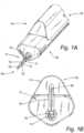
FIGS. 1A-1C depict one example of acautery device 10 having aproximal end 30 and adistal end 40. In thecautery device 10 depicted inFIGS. 1A-1C , thedevice 10 includes abody 20 with abipolar cautery component 12 at thedistal end 40. - Known minimally-invasivein vivo cautery devices use a monopolar hook cautery component. In contrast, the examples disclosed herein provide a different device that cauterizes and cuts vessels with more precision and with reduced damage to the surrounding tissue.
- As best shown in
FIGS. 1A-1C , thebipolar cautery component 12, also termed a"cautery end effector" herein, includes astationary jaw component 14, amobile jaw component 16 for clasping and cauterizing a vessel (e.g., a vein or artery), and acutting component 18 for cutting the cauterized vessel, thus providing a threefunction end effector 12. Thestationary jaw component 14 andmobile jaw component 16 are structured like a pair of jaws, with thestationary jaw component 14 being configured to remain stationary during the cautery process, providing a substantially rigid and stable base to support a vessel. Themobile jaw component 16 is configured such that it can move in a jaw-like fashion in relation to thestationary jaw component 14 such that themobile jaw component 16 can ultimately make contact with the vessel positioned between thestationary jaw component 14 and themobile jaw component 16 to clasp the vessel between thejaws - As best shown in
FIGS. 6 and7 , according to one example, themobile jaw 16 additionally includes apivot component 13 that that projects laterally from the proximal end ofmobile jaw 16 and includes areceptacle 13a for receiving apin 13b. Thepivot component 13 is generally peg- or wedge-shaped to fit through an opening inouter shell 15 and facilitates movement ofmobile jaw 16 as described herein below.Stationary jaw 14 includes anopening 14a configured to align withreceptacle 13 and receivepin 13b. - Returning to
FIGS. 1A-1C , each of the fixedjaw component 14 andmobile jaw component 16 is connected to a source of electrical current (not shown) such that thejaws device 10 as a separate component. In use, the electricity flowing through thejaws jaws - The
stationary jaw 14 of the bipolarcautery end effector 12 is attached to a shaft 32 that extends proximally from thestationary jaw 14 and is disposed within thebody 20. The cuttingcomponent 18 is positioned between thejaws 14, 16 (as shown inFIGS. 1A-1C ) and extends through the shaft 32. The shaft 32 has a slot 39 cut into either or both the top 34 or bottom 36 sides of the shaft 32 and extending longitudinally along part of the length of the shaft 32 to accommodate a pin 38 that extends through the slot 39 and attaches to or extends through the cuttingcomponent 18 such that the pin is coupled to the cutting component. As such, the pin 38 and cuttingcomponent 18 can slide together along the slot 39 from a generally proximal first position to a more distal second position along with the cuttingcomponent 18. In some examples as best shown inFIG. 5 , one or both of thestationary jaw 14 andmobile jaw 16 have achannel cutting component 18 moves from the first position to the second position. - The cutting
component 18 is substantially elongate and has a proximal end 24 and a distal end 25. The cuttingcomponent 18 includes a cuttingsurface 22 at the distal end 25 such that when thecutting component 18 is moved from the generally proximal first position to the more distal second position, the cauterized vessel enclosed between thejaws cautery device 10 is cut at the point of cautery. - For ease of description and understanding, the
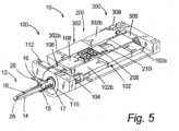
cautery device 10 as described herein has threesections FIG. 2 . In this example, each section generally defines a plurality of components configured to control a function of thecautery device 10 within thebody 20. As such, thefirst section 100 controls the application of the electrical current to thejaws cautery end effector 12. Thesecond section 200 controls positioning of thecutting component 18. Finally, thethird section 300 controls opening and closing of thejaws cautery end effector 12. It is to be understood that while the illustrated examples utilize three sections, this identification and division of sections is provided solely for ease of description and understanding. It is also understood that the sections may be combined or split into more or fewer sections. For example, thefirst section 100 may be split into two sections separately controlling electrical current and end effector rotation. - According to some examples, the sections are configured and positioned such that the
first section 100 is proximal to the bipolarcautery end effector 12, while thethird section 300 is located closest to theproximal end 30 of thedevice 10, with thesecond section 200 being located between the first andthird sections cautery device 10 becomes more slender toward the distal end. It is to be understood, however, that the sections may be configured or positioned in any manner suitable for proper function of the device, and may include any modifications that provide functional, aesthetic, and/or manufacturing advantages. Such advantages include, without limitation, visibility of the bipolarcautery end effector 12, size reduction, reduced materials costs, and the like. - Power for the various functions of the
device 10 as described herein is provided by themotors FIG. 5 . Electrical current for themotors device 10. Alternatively, the electrical source can be positioned within the device. In some examples, the source of electricity formotors motors motors motors motor motors jaws - As best shown in
FIG. 5 , one or more ofmotors motors more motors - In accordance with one implementation, due to the electrical nature of the bipolar
cautery end effector 12, the drivetrain - including the first 100, second 200, and third 300 sections of the device - is electrically isolated from themotors motors jaws motors FIG. 5 , gears 106, 208, 306 are made of non-conductive material, whilegears encoder - As best shown in
FIGS. 3A and5 , thefirst section 100 of thecautery device 10 includes afirst section motor 102 that is operatively coupled to the bipolarcautery end effector 12 to control rotation of the bipolarcautery end effector 12. In some examples, thefirst section motor 102 is directly coupled to the bipolarcautery end effector 12 or can be indirectly coupled to the bipolarcautery end effector 12 by one or more coupling means. For example, in the example illustrated inFIGS. 3A and 3B , thefirst section motor 102 is coupled to the bipolarcautery end effector 12 by afirst gear 104 and asecond gear 106, thesecond gear 106 being attached to the shaft 32 of the bipolarcautery end effector 12 viametal coupler 108, as best shown inFIG. 5 , such that rotational movement produced by thefirst section motor 102 is transferred to rotational movement of the bipolarcautery end effector 12 around axis A depicted inFIG. 3A . In some examples,metal coupler 108 is coupled to the bipolarcautery end effector 12 via anouter shell 15. As best shown inFIGS. 6 and7 ,outer shell 15 projects distally from themetal coupler 108 and includes anopening 15a through whichpivot component 13 onmobile jaw 16 projects and translates rotational movement ofcoupler 108 to shaft 32. Second gear 106 can be fixed to themetal coupler 108 using, for example, an adhesive (e.g., UV cure glue). In some examples, thesecond gear 106 and themetal coupler 108 are configured such that the shape of each component prevents thesecond gear 106 from moving relative to the metal coupler 108 (i.e., non-circular geometry). For example, themetal coupler 108 can be generally square-shaped to fit into a generally square-shaped hole in thesecond gear 106.- The
first section 100 additionally includes components for applying electrical current to thejaws first section 100 includes anelectrical connection 110 for themobile jaw 16. Theelectrical connection 110 is configured to allow sliding contact to afirst slip ring 112, which is connected to a source of electrical current (not shown) either directly or indirectly.Slip ring 112 is generally U-shaped or C-shaped such that it maintains contact withelectrical connection 110 whenelectrical connection 110 rotates with shaft 36. The use ofslip ring 112 rather than a wire to provide electrical connection toconnection 110 prevents twisting of wires about the drive train asconnection 110 rotates.Mobile jaw 16 is electrically connected toconnection 110 via a conductor, such aswire 13c shown inFIG. 7 or other appropriate conductor.Electrical connection 110 is electrically isolated fromstationary jaw 14 by the inclusion of a non-conductive (e.g., plastic)ring 17 between theconnection 110 and thestationary jaw 14. The first section also includes a second slip ring 114 associated with thestationary jaw 14, that functions similarly to thefirst slip ring 112 by maintaining electrical contact with shaft 36 during rotation. The use ofslip rings 112, 114 to separately provide current tojaws jaws - The
second section 200 in the example includes a second section motor 202 that is operatively coupled to thecutting component 18 to control movement of thecutting component 18 from a first position to a second position along line of movement M. The second section motor 202 is coupled to a threaded collar 204 either directly or indirectly via a coupling means. The coupling means for coupling the second section motor 202 to the threaded collar 204 includes a first gear 206 connecting the second section motor 202 to asecond gear 208, thesecond gear 208 being attached to the threaded collar 204 using, for example, an adhesive (e.g., UV cure glue) or non-circular geometry, as described above. An end of the pin 38 attached to or extending through the cuttingcomponent 18 is seated in a thread 212 of the threaded collar 204 such that rotational movement produced by the second section motor 202 is translated to lateral movement of the pin 38 along M and thereby thecutting component 18. The second section is configured such that the movement of thecutting component 18 along M is a distance ranging from about 0.5 inches (1.27 centimetres) to about 1.0 inches (2.54 centimetres) in order to cut a vessel clasped betweenjaws cautery device 10. In one example, thepivot component 13 ofmobile jaw 16 includes an opening through which thecutting component 18 passes when moved. When not being used to cut a vessel, the cuttingcomponent 18 is retracted to a position proximal to thejaws mobile jaw 16 may be opened or closed. - The
third section 300 illustrated inFIG. 5 includes athird section motor 302 that is operatively coupled tomobile jaw 16 to control opening and closing of thejaws third section motor 302 is directly coupled to shaft 32 or can be indirectly coupled to shaft 32 by one or more coupling means. For example, in the example illustrated in FIGS. 4 and5 , thethird section motor 302 is coupled to the shaft 32 by afirst gear 308 and asecond gear 306, thesecond gear 306 being attached to collar 310 using, for example, an adhesive (e.g., UV cure glue) or non-circular geometry. In some examples, the shaft 32 and collar 310 are threaded such that rotation produced bymotor 302 is translated to lateral movement of the shaft 32 along M and thereby thejaws outer shell 15. As best seen inFIG. 6 ,opening 15a restricts lateral movement ofpivot component 13 ofmobile jaw 16 along M relative toouter shell 15 such that lateral translation of shaft 32 along M causesmobile jaw 16 to open or close by pivoting aroundpin 13b via thepivot component 13 atopening 15a. - In an alternative example,
stationary jaw 14 can be replaced with a second mobile jaw. In this example, the second mobile jaw is pivotably attached to shaft 32 and includes a pivot component similar to pivotcomponent 13. In this example,outer shell 15 is configured to include a second opening similar toopening 15a that restricts lateral movement of the pivot component of the second mobile jaw such that the second mobile jaw is opened and closed via translation of shaft 32 along M in a manner similar tomobile jaw 16. - The
third section 300 can further include a means for detecting the thickness of a vessel clasped between thejaws mobile jaw 16 or the position ofmobile jaw 16 relative tostationary jaw 14. In some examples, the position ofmobile jaw 16 relative tostationary jaw 14 is determined for example, by measuring electrical impedance betweenjaws - As discussed above, the cautery device examples disclosed herein can be utilized in any type of medical device, including those devices in which a compact or smaller size is desirable, such as devices for procedures to be performed within a patient. In order to achieve a cautery device with appropriate dimensions for such use, the dimensions of components disclosed herein can be adjusted to control the overall size of the device. For example, in one implementation, the
motors - In use, the
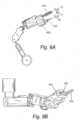
cautery device 20 is positioned next to the target vessel using a complementary system or device as described elsewhere such as an articulating robotic arm. Next, thecautery device 20 operates in the following manner to cauterize the vessel. Thefirst section motor 102 rotates thecautery end effector 12 to position thejaws third section motor 302 actuates themobile jaw 16 to open and thecautery end effector 12 is positioned such that the vessel is located between thejaws third section motor 302 then actuates themobile jaw 16 to close with the vessel disposed between thejaws jaws cutting component 18 toward the distal end of thecautery device 20 and thus pushes the cuttingsurface 22 through the vessel enclosed in thejaws FIGS. 8A-22 depict a dual end effectoroperational component 410 that can be incorporated into any one of a variety of medical devices as described above. In this embodiment, the dual end effectoroperational component 410 is positioned on the end of a robotic arm 412. It is further understood that the robotic arm 412 can be part of any robotic medical device, such as an in vivo device. As best shown inFIGS. 8A-10B , the arm 412 has two arm segments, including a first arm segment (or "upper arm") 412A and a second arm segment (or "forearm") 412B. Thefirst arm segment 412A is rotatably coupled with atorso motor housing 414 via a joint or hinge (not shown). Thetorso motor housing 414 houses a motor and actuation mechanism (not shown) to provide rotation of thefirst arm segment 412A relative to thetorso motor housing 414. Further, thefirst arm segment 412A is rotatably coupled to thesecond arm segment 412B at joint 416A, while thesecond arm segment 412B is rotatably coupled to the dual end effector operational component 41 0 at joint 416B.- In one embodiment, the dual end effector
operational component 410 has anactuator housing 418 and anend effector housing 420. Theend effector housing 420 has twoend effector elements FIGS. 8A-10B , one end effector element is acautery component 422 and the second end effector element is agrasper 424. Alternatively, the end effector elements on the dual end effectoroperational component 410 can be any known end effectors for use with medical devices, such as, for example, forceps, needle drivers, scissors, Ligasure™, or knife components, to list a few. - As best shown in
FIGS. 8A and 8B , in one embodiment, although bothend effector elements end effector housing 420 is oriented so that thegrasper 424 is accessible to the subject tissue and can perform a medical procedure. - As best shown in
FIGS. 9A and 9B , in another embodiment, although bothend effector elements end effector housing 420 is oriented so that thecautery component 422 is accessible to the subject tissue and can perform a medical procedure. - In one embodiment, both
end effector elements end effector housing 420. More specifically, as best shown inFIG. 9A , thecautery component 422 is rotatable relative to theend effector housing 420 as shown by arrow AA around an axis indicated by line A. Further, thegrasper 424 is rotatable relative to theend effector housing 420 as shown by arrow BB around an axis indicated by line B. According to one embodiment, thegrasper 424 is also configured to move between an open configuration and a closed configuration (not shown). In an alternative embodiment (not shown), bothend effector elements end effector housing 420 and also can be configured to move between an open configuration and a closed configuration, depending on the type of end effectors. In another alternative embodiment, the two end effectors can be operably coupled to each other such that both end effectors can be configured to move between open and closed positions. - As best shown in
FIG. 10A , in one embodiment, the dual end effectoroperational component 410 can be rotated relative to thesecond arm segment 412B via the joint 416B and an actuation motor and gear system (not shown) contained within thesecond arm segment 412B. - As best shown in
FIG. 10B , in one embodiment, the dual end effectoroperational component 410 and thesecond arm segment 412B can be rotated relative to thefirst arm segment 412A via the joint 416A and an actuation motor and gear system (not shown) within thefirst arm segment 412A. - As best shown in
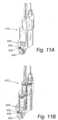
FIGS. 1 1 A-12B , within thedual end effector 410, theforearm gear housing 426 contains anactuation motor 428 that is rigidly coupled to adriveshaft 430. Thedriveshaft 430 is rigidly coupled to a rotationalmotor spur gear 432. The rotationalmotor spur gear 432 is rotatably coupled to arotational gear 434 that is rigidly coupled to the second arm segment (such as, for example, thesecond arm segment 412B as shown inFIGS. 8A-10B ). Actuation of theactuation motor 428 causes rotation of thedriveshaft 430 and the rotationalmotor spur gear 432. Rotation of the rotationalmotor spur gear 432 causes rotation of the dual end effectoroperational component 410 relative to the second arm segment (such assecond arm segment 412B). - As best shown in
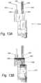
FIGS. 13A and 13B , in one embodiment, thecautery component 422 has aproximal cautery housing 436 rigidly attached to adistal cautery tip 438. In one embodiment, the wire (not shown) supplying electricity to thecautery tip 438 is enclosed in thecautery housing 436. The wire runs proximally through the dual end effector operational component 41 0 and is coupled at a proximal end of the wire to a power source such as a standard electrocautery generator (not shown). In another embodiment, the power source could be located within the dual end effectoroperational component 410. According to the implementation as shown, thegrasper 424 has aproximal grasper housing 440 coupled to twograsping elements - As best shown in
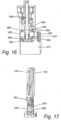
FIG. 13B , in one embodiment, thecautery housing 436 is rigidly coupled to a cauteryrotational gear 446 within theend effector housing 420. Further, thegrasper housing 440 is rigidly connected to the grasperrotational spur gear 448 within theend effector housing 420. - As best shown in
FIG. 14 , the cauteryrotational gear 446 is rotatably coupled with a rotationalmotor spur gear 450. The rotationalmotor spur gear 450 is rotatably actuated by arotational motor 452 and arotational motor gearhead 454 coupled to themotor 452. Actuation of therotational motor 452 androtational motor gearhead 454 causes rotation of the rotationalmotor spur gear 450, and thus the cauteryrotational gear 446 and thecautery housing 436. Thecautery housing 436 is further coupled to two bearingelements distal bearing 456 and aproximal bearing 458, both of which support thecautery housing 436 and reduce rotational friction thereof. Thecautery housing 436 andproximal bearing 458 are further coupled to a cauteryhousing preload nut 460 that limits translation of thecautery housing 436 and provides a preload or clamping force for the two bearingelements cautery housing 436 by holding the bearingelements - In one embodiment, the grasper
rotational spur gear 448 is rotatably coupled with the rotationalmotor spur gear 450. Actuation of therotational motor 452 androtational motor gearhead 454 causes rotation of the rotationalmotor spur gear 450, and thus causes rotation of the grasperrotational spur gear 448 and thegrasper housing 440 simultaneously with rotation of thecautery housing 436. - In one embodiment, proximal to the grasper
rotational spur gear 448, thegrasper housing 440 is coupled to two beveled washer elements - a distalbeveled washer element 462 and a proximal beveled washer element 464 - that provide compliance for the grasper and prevent contact between moving parts during rotation of thegrasper housing 440. Thegrasper housing 440 is further coupled to two bearing elements - adistal bearing 466 and a proximal bearing 468 - that provide support for and reduce rotational friction of thegrasper housing 440. Thegrasper housing 440 is further coupled to a distalhex preload nut 470 that limits translation of thegrasper housing 440 and provides a preload or clamping force for thebearings grasper housing 440 by holding thebearings - In one embodiment, an
actuation motor 472 is rigidly coupled to anactuation motor housing 474 by two actuationmotor mounting bolts motor mounting bolts actuation motor 472 to theactuation motor housing 474. - As best shown in
FIG. 15 , in one embodiment, theactuation motor 472 is rigidly coupled to the actuationmotor spur gear 480. Actuation of theactuation motor 472 causes rotation of the actuationmotor spur gear 480 and this rotation is translated to the driveshafthousing spur gear 482. - As best shown in
FIG. 16 , the driveshafthousing spur gear 482 is rigidly coupled to thedriveshaft housing 484 which is, in turn, rotatably coupled to thegrasper driveshaft 486. Rotation of the driveshafthousing spur gear 482 via actuation of theactuation motor 472 and the actuationmotor spur gear 480 therefore results in rotation of thedriveshaft housing 484. Rotation of thedriveshaft housing 484 in turn causes translation of thegrasper driveshaft 486. - In one embodiment, rotation of the
driveshaft housing 484 is aided by a proximalhex preload nut 488, severalbeveled washer elements elements driveshaft housing 484 is further rigidly coupled to adriveshaft housing screw 500 that constrains translation of thedriveshaft housing 484 to theproximal bearing 498. - As best shown in
FIG. 17 , a grasperrotational pin 502 is threaded through one side of thegrasper housing 440, through a hole in each of thegrasping elements grasper housing 440. As thegrasper driveshaft 486 is translated via rotation of the driveshaft housing 484 (as best shown inFIG. 16 ), aconnector pin 504 that connects thegrasper driveshaft 486 to thegrasper elements grasper elements grasper elements - As best shown in
FIGS. 18 and 19 , thecautery component 422 can extend and retract as necessary for operation and accessibility of the desired end effector element. As best shown inFIG. 18 , thecautery component 422 can be retracted through retraction of theretractable cautery shaft 506 during operation of thegrasper 424 so that unwanted contact with tissue by thecautery component 422 can be avoided. As best shown inFIG. 19 , during operation of thecautery component 422, thecautery component 422 can be extended beyond the proximal tip of thegrasper 424 by extension of theretractable cautery shaft 506. - As best shown in
FIGS. 20 and 21 , thecautery component 422 is extended and retracted through rotation of the rotationalmotor spur gear 450. The rotationalmotor spur gear 450 is rotatably coupled to the upperlong cautery shaft 508. The upperlong cautery shaft 508 is rigidly coupled to the lowerlong cautery shaft 510 via aset screw 512. The lowerlong cautery shaft 510 is supported by two bearingelements long cautery shaft 510 is rotatably coupled to theretractable cautery shaft 506. - As best shown in
FIG. 22 , rotation of the lower long cautery shaft 510 (depicted inFIGS. 20 and 21 ) causes theretractable cautery shaft 506 to retract or extend via external threading on theretractable cautery shaft 506 and internal threading on the threadedcautery energizing ring 518. The external threading of theretractable cautery shaft 506 causes theretractable cautery shaft 506 to translate up and down when the lower long cautery shaft 510 (depicted inFIGS. 20 and 21 ) is rotated. Power is supplied to thecautery component 422 via a wire (not shown) connected to the energizingring 518. - Although the present invention has been described with reference to preferred embodiments and examples, persons skilled in the art will recognize that changes may be made in form and detail without departing from the scope of the invention as defined by the appended claims.
Claims (10)
- An in-vivo vessel sealing end effector, the end effector comprising:a) an in vivo end effector body coupleable to an arm of an in vivo robotic device, wherein the end effector body is configured to be positioned entirely within a cavity of a patient, the end effector body comprising:(i) a cautery component shaft (38) disposed within the body and operably coupled to a jaw actuation motor; and(ii) a first threaded collar (204) disposed around and operably coupled to the cautery component shaft (38); andb) a bipolar vessel cautery component (12) operably coupled to a cautery component actuation motor and to the end effector body, the cautery component comprising:(i) a stationary jaw (14) coupled to a distal end (40) of the cautery component shaft;(ii) a mobile jaw (16) pivotally coupled to the distal end of the cautery component shaft; and(iii) a cutting component (18) operably coupled to a cutting component actuation motor and moveably coupled to the cautery component shaft (38).
- The end effector of claim 1, wherein the cautery component (422) is rotatable about an axis parallel with the shaft.
- The end effector of claim 1, wherein the overall length of the end effector body is under 3 inches (7.62 cm).
- The end effector of claim 1, wherein the first threaded collar is threadably coupled with the cautery component shaft (38) such that rotation of the collar causes axial movement of the cautery component shaft, thereby causing the mobile jaw (16) to move between open and closed positions.
- The end effector of claim 4, further comprising:(a) a second collar (310) rotatably disposed within the end effector body(b) a translation shaft (32) fixedly coupled to the cutting component and operably coupled to the second collar,
such that rotation of the second collar causes axial movement of the cutting component between retracted and deployed positions. - The end effector of claim 1, wherein the stationary jaw (14) is configured to provide a stable base to support a vessel to be cauterized.
- The end effector of claim 1, wherein rotation of the translation shaft (32) causes rotation of the mobile (16) and stationary jaws (14).
- The end effector of claim 1, further comprising:(a) an electrical connection (110) rotatably fixed to the cautery component shaft (506), wherein the electrical connection is electrically coupled to one of the mobile jaw (16) and the stationary jaw (14);(b) a first slip ring (112) coupled to the end effector body, wherein the first slip ring is configured to maintain electrical contact with the electrical connection during rotation of the cautery component shaft;(c) an external electrical source electrically coupled to the first slip ring (112); and(d) a second slip ring (114) coupled to the end effector body, wherein the second slip ring is configured to maintain electrical contact with the cautery component shaft during rotation of the cautery component shaft, wherein the second slip ring is electrically coupled to the external electrical source.
- The end effector of claim 1, further comprising:(a) an electrical connection (110) rotatably fixed to the cautery component shaft (38); and(b) a first slip ring (112) coupled to the end effector body, wherein the first slip ring is configured to maintain electrical contact with the electrical connection during rotation of the cautery component shaft,wherein the electrical connection is electrically coupled to one of the mobile jaw (16) and the stationary jaw (14).
- The end effector of claim 9, further comprising an electrical source electrically coupled to the first slip ring.
Priority Applications (1)
| Application Number | Priority Date | Filing Date | Title |
|---|---|---|---|
| EP23200253.5AEP4275634A3 (en) | 2011-06-10 | 2012-06-11 | Surgical end effector |
Applications Claiming Priority (5)
| Application Number | Priority Date | Filing Date | Title |
|---|---|---|---|
| US201161495487P | 2011-06-10 | 2011-06-10 | |
| US201161498919P | 2011-06-20 | 2011-06-20 | |
| EP12836073.2AEP2717796B1 (en) | 2011-06-10 | 2012-06-11 | In vivo vessel sealing end effector |
| EP20159331.6AEP3714821A1 (en) | 2011-06-10 | 2012-06-11 | Surgical end effector |
| PCT/US2012/041911WO2013048595A1 (en) | 2011-06-10 | 2012-06-11 | Methods, systems, and devices relating to surgical end effectors |
Related Parent Applications (2)
| Application Number | Title | Priority Date | Filing Date |
|---|---|---|---|
| EP20159331.6ADivisionEP3714821A1 (en) | 2011-06-10 | 2012-06-11 | Surgical end effector |
| EP12836073.2ADivisionEP2717796B1 (en) | 2011-06-10 | 2012-06-11 | In vivo vessel sealing end effector |
Related Child Applications (2)
| Application Number | Title | Priority Date | Filing Date |
|---|---|---|---|
| EP23200253.5ADivisionEP4275634A3 (en) | 2011-06-10 | 2012-06-11 | Surgical end effector |
| EP23200253.5ADivision-IntoEP4275634A3 (en) | 2011-06-10 | 2012-06-11 | Surgical end effector |
Publications (2)
| Publication Number | Publication Date |
|---|---|
| EP3977951A1 EP3977951A1 (en) | 2022-04-06 |
| EP3977951B1true EP3977951B1 (en) | 2023-11-08 |
Family
ID=47677994
Family Applications (4)
| Application Number | Title | Priority Date | Filing Date |
|---|---|---|---|
| EP12836073.2AActiveEP2717796B1 (en) | 2011-06-10 | 2012-06-11 | In vivo vessel sealing end effector |
| EP21211185.0AActiveEP3977951B1 (en) | 2011-06-10 | 2012-06-11 | Surgical end effector |
| EP20159331.6AWithdrawnEP3714821A1 (en) | 2011-06-10 | 2012-06-11 | Surgical end effector |
| EP23200253.5APendingEP4275634A3 (en) | 2011-06-10 | 2012-06-11 | Surgical end effector |
Family Applications Before (1)
| Application Number | Title | Priority Date | Filing Date |
|---|---|---|---|
| EP12836073.2AActiveEP2717796B1 (en) | 2011-06-10 | 2012-06-11 | In vivo vessel sealing end effector |
Family Applications After (2)
| Application Number | Title | Priority Date | Filing Date |
|---|---|---|---|
| EP20159331.6AWithdrawnEP3714821A1 (en) | 2011-06-10 | 2012-06-11 | Surgical end effector |
| EP23200253.5APendingEP4275634A3 (en) | 2011-06-10 | 2012-06-11 | Surgical end effector |
Country Status (5)
| Country | Link |
|---|---|
| US (6) | US9060781B2 (en) |
| EP (4) | EP2717796B1 (en) |
| JP (1) | JP6174017B2 (en) |
| CA (1) | CA2838637C (en) |
| WO (1) | WO2013048595A1 (en) |
Families Citing this family (53)
| Publication number | Priority date | Publication date | Assignee | Title |
|---|---|---|---|---|
| US7960935B2 (en) | 2003-07-08 | 2011-06-14 | The Board Of Regents Of The University Of Nebraska | Robotic devices with agent delivery components and related methods |
| US9579088B2 (en) | 2007-02-20 | 2017-02-28 | Board Of Regents Of The University Of Nebraska | Methods, systems, and devices for surgical visualization and device manipulation |
| US8679096B2 (en) | 2007-06-21 | 2014-03-25 | Board Of Regents Of The University Of Nebraska | Multifunctional operational component for robotic devices |
| WO2007149559A2 (en) | 2006-06-22 | 2007-12-27 | Board Of Regents Of The University Of Nebraska | Magnetically coupleable robotic devices and related methods |
| US8343171B2 (en) | 2007-07-12 | 2013-01-01 | Board Of Regents Of The University Of Nebraska | Methods and systems of actuation in robotic devices |
| JP2010536435A (en) | 2007-08-15 | 2010-12-02 | ボード オブ リージェンツ オブ ザ ユニバーシティ オブ ネブラスカ | Medical inflation, attachment and delivery devices and associated methods |
| CA2695619C (en) | 2007-08-15 | 2015-11-24 | Board Of Regents Of The University Of Nebraska | Modular and cooperative medical devices and related systems and methods |
| WO2011075693A1 (en) | 2009-12-17 | 2011-06-23 | Board Of Regents Of The University Of Nebraska | Modular and cooperative medical devices and related systems and methods |
| EP2600758A1 (en) | 2010-08-06 | 2013-06-12 | Board of Regents of the University of Nebraska | Methods and systems for handling or delivering materials for natural orifice surgery |
| WO2012047939A2 (en)* | 2010-10-04 | 2012-04-12 | Ind Platforms Llc | Expandable devices, rail systems, and motorized devices |
| JP6174017B2 (en) | 2011-06-10 | 2017-08-02 | ボード オブ リージェンツ オブ ザ ユニバーシティ オブ ネブラスカ | In vivo vascular seal end effector and in vivo robotic device |
| WO2013009887A1 (en) | 2011-07-11 | 2013-01-17 | Board Of Regents Of The University Of Nebraska | Robotic surgical devices, systems and related methods |
| WO2013052137A2 (en) | 2011-10-03 | 2013-04-11 | Board Of Regents Of The University Of Nebraska | Robotic surgical devices, systems and related methods |
| WO2013106569A2 (en) | 2012-01-10 | 2013-07-18 | Board Of Regents Of The University Of Nebraska | Methods, systems, and devices for surgical access and insertion |
| US10179033B2 (en) | 2012-04-26 | 2019-01-15 | Bio-Medical Engineering (HK) Limited | Magnetic-anchored robotic system |
| US8891924B2 (en) | 2012-04-26 | 2014-11-18 | Bio-Medical Engineering (HK) Limited | Magnetic-anchored robotic system |
| EP2844181B1 (en) | 2012-05-01 | 2021-03-10 | Board of Regents of the University of Nebraska | Single site robotic device and related systems |
| EP3189948B1 (en) | 2012-06-22 | 2018-10-17 | Board of Regents of the University of Nebraska | Local control robotic surgical devices |
| RU2686954C2 (en)* | 2012-06-28 | 2019-05-06 | Конинклейке Филипс Н.В. | Navigation by optical fiber sensor for visualization and monitoring of vessels |
| EP2882331A4 (en) | 2012-08-08 | 2016-03-23 | Univ Nebraska | ROBOTIC SURGICAL SYSTEMS AND DEVICES, AND ASSOCIATED METHODS |
| US12295680B2 (en) | 2012-08-08 | 2025-05-13 | Board Of Regents Of The University Of Nebraska | Robotic surgical devices, systems and related methods |
| US9770305B2 (en) | 2012-08-08 | 2017-09-26 | Board Of Regents Of The University Of Nebraska | Robotic surgical devices, systems, and related methods |
| US20140066900A1 (en)* | 2012-09-06 | 2014-03-06 | Corindus, Inc. | System for guide catheter control |
| CA2905948C (en) | 2013-03-14 | 2022-01-11 | Board Of Regents Of The University Of Nebraska | Methods, systems, and devices relating to robotic surgical devices, end effectors, and controllers |
| CA2906672C (en) | 2013-03-14 | 2022-03-15 | Board Of Regents Of The University Of Nebraska | Methods, systems, and devices relating to force control surgical systems |
| CA2906772C (en)* | 2013-03-15 | 2021-09-21 | Board Of Regents Of The University Of Nebraska | Robotic surgical devices, systems and related methods |
| US10966700B2 (en) | 2013-07-17 | 2021-04-06 | Virtual Incision Corporation | Robotic surgical devices, systems and related methods |
| CA2961213A1 (en) | 2014-09-12 | 2016-03-17 | Board Of Regents Of The University Of Nebraska | Quick-release end effectors and related systems and methods |
| EP3217890B1 (en) | 2014-11-11 | 2020-04-08 | Board of Regents of the University of Nebraska | Robotic device with compact joint design |
| WO2016133631A1 (en) | 2015-02-16 | 2016-08-25 | Covidien Lp | Robotic surgical assemblies and electrosurgical instruments thereof |
| WO2017024081A1 (en) | 2015-08-03 | 2017-02-09 | Board Of Regents Of The University Of Nebraska | Robotic surgical devices systems and related methods |
| CN108289713B (en)* | 2015-09-25 | 2021-07-27 | 柯惠Lp公司 | Robotic surgical components and their electromechanical instruments |
| US20170258519A1 (en) | 2016-03-10 | 2017-09-14 | RELIGN Corporation | Arthroscopic devices and methods |
| US11207119B2 (en) | 2016-03-11 | 2021-12-28 | RELIGN Corporation | Arthroscopic devices and methods |
| US10595889B2 (en) | 2016-04-11 | 2020-03-24 | RELIGN Corporation | Arthroscopic devices and methods |
| US11172953B2 (en) | 2016-04-11 | 2021-11-16 | RELIGN Corporation | Arthroscopic devices and methods |
| CA3024623A1 (en) | 2016-05-18 | 2017-11-23 | Virtual Incision Corporation | Robotic surgical devices, systems and related methods |
| WO2018008106A1 (en)* | 2016-07-06 | 2018-01-11 | オリンパス株式会社 | Medical instrument holding device, medical system, medical instrument holding device operating method, and medical system operating method |
| CA3034671A1 (en) | 2016-08-25 | 2018-03-01 | Shane Farritor | Quick-release tool coupler and related systems and methods |
| WO2018045036A1 (en)* | 2016-08-30 | 2018-03-08 | Board Of Regents Of The University Of Nebraska | Robotic device with compact joint design and an additional degree of freedom and related systems and methods |
| CN115337111B (en) | 2016-11-22 | 2025-04-25 | 内布拉斯加大学董事会 | Improved coarse positioning device and related system and method |
| CN115553922A (en) | 2016-11-29 | 2023-01-03 | 虚拟切割有限公司 | User controller with user presence detection and related systems and methods |
| US10717166B2 (en)* | 2016-12-02 | 2020-07-21 | General Electric Company | Motorized apparatus for use with rotary machines |
| WO2018112199A1 (en) | 2016-12-14 | 2018-06-21 | Virtual Incision Corporation | Releasable attachment device for coupling to medical devices and related systems and methods |
| JP2020534931A (en)* | 2017-09-26 | 2020-12-03 | リライン コーポレーション | Arthroscopic device and method |
| CN117017492A (en)* | 2017-09-27 | 2023-11-10 | 虚拟切割有限公司 | Robotic surgical device with tracking camera technology and related systems and methods |
| WO2019089305A1 (en)* | 2017-10-30 | 2019-05-09 | Ethicon Llc | Surgical suturing instrument configured to manipulate tissue using mechanical and electrical power |
| CA3087672A1 (en) | 2018-01-05 | 2019-07-11 | Board Of Regents Of The University Of Nebraska | Single-arm robotic device with compact joint design and related systems and methods |
| CN108742782B (en)* | 2018-04-09 | 2022-05-31 | 杭州康亚医疗器械有限公司 | Multifunctional surgical grasping forceps for laparoscopy |
| WO2020146348A1 (en) | 2019-01-07 | 2020-07-16 | Virtual Incision Corporation | Robotically assisted surgical system and related devices and methods |
| WO2020261208A2 (en)* | 2019-06-28 | 2020-12-30 | Auris Health, Inc. | Patient introducer for a robotic system |
| JP2023532977A (en) | 2020-07-06 | 2023-08-01 | バーチャル インシジョン コーポレイション | Surgical robotic positioning system and related apparatus and methods |
| GB2599101B (en)* | 2020-09-23 | 2025-02-12 | Cmr Surgical Ltd | Arrangement of end effector elements |
Family Cites Families (470)
| Publication number | Priority date | Publication date | Assignee | Title |
|---|---|---|---|---|
| US3870264A (en) | 1973-03-26 | 1975-03-11 | William I Robinson | Stand |
| DE2339827B2 (en) | 1973-08-06 | 1977-02-24 | A6 In 3-02 | DENTAL EQUIPMENT |
| JPS5115425A (en) | 1974-07-29 | 1976-02-06 | Yashica Co Ltd | DENJIRERIIZUSHIKISUCHIIRUKAMERANIOKERU MOOTADORAIBUSOCHI |
| US4258716A (en) | 1978-02-06 | 1981-03-31 | The University Of Melbourne | Microsurgical instruments |
| JPS5519124A (en) | 1978-07-27 | 1980-02-09 | Olympus Optical Co | Camera system for medical treatment |
| US4246661A (en) | 1979-03-15 | 1981-01-27 | The Boeing Company | Digitally-controlled artificial hand |
| JPS58132490A (en) | 1982-01-29 | 1983-08-06 | 株式会社日立製作所 | Angle transmission mechanism |
| JPS5959371A (en) | 1982-09-30 | 1984-04-05 | フアナツク株式会社 | Industrial robot |
| US5307447A (en) | 1982-10-29 | 1994-04-26 | Kabushiki Kaisha Toshiba | Control system of multi-joint arm robot apparatus |
| GB2130889B (en) | 1982-11-26 | 1986-06-18 | Wolf Gmbh Richard | Rectoscope |
| JPS6076986A (en) | 1983-09-30 | 1985-05-01 | 株式会社東芝 | Robot |
| DE3337797C1 (en) | 1983-10-18 | 1985-04-11 | Jean Walterscheid Gmbh, 5204 Lohmar | Pull lock that can be locked in open position |
| DE3536747A1 (en) | 1984-10-15 | 1986-04-24 | Tokico Ltd., Kawasaki, Kanagawa | Joint mechanism |
| DE3525806A1 (en) | 1985-07-19 | 1987-01-29 | Kuka Schweissanlagen & Roboter | TRANSMISSION HEAD FOR MANIPULATORS |
| JPS6268293A (en) | 1985-09-20 | 1987-03-28 | 株式会社明電舎 | Manipulator shoulder mechanism |
| DE3545068A1 (en) | 1985-12-19 | 1987-06-25 | Kuka Schweissanlagen & Roboter | TRANSMISSION HEAD FOR MANIPULATORS |
| DE3612498A1 (en) | 1986-04-14 | 1987-10-29 | Norske Stats Oljeselskap | SELF-DRIVING VEHICLE FOR PIPELINES |
| US4787270A (en) | 1987-02-11 | 1988-11-29 | Cincinnati Milacron Inc. | Robotic manipulator |
| JP2591968B2 (en) | 1987-12-28 | 1997-03-19 | 株式会社日立製作所 | Industrial robot wrist |
| US5187796A (en) | 1988-03-29 | 1993-02-16 | Computer Motion, Inc. | Three-dimensional vector co-processor having I, J, and K register files and I, J, and K execution units |
| US5019968A (en) | 1988-03-29 | 1991-05-28 | Yulan Wang | Three-dimensional vector processor |
| US5108140A (en) | 1988-04-18 | 1992-04-28 | Odetics, Inc. | Reconfigurable end effector |
| US4896015A (en) | 1988-07-29 | 1990-01-23 | Refractive Laser Research & Development Program, Ltd. | Laser delivery system |
| US4897014A (en) | 1988-09-06 | 1990-01-30 | Harbor Branch Oceanographic Institution, Inc. | Device for interchange of tools |
| US5271384A (en) | 1989-09-01 | 1993-12-21 | Mcewen James A | Powered surgical retractor |
| US5201325A (en) | 1989-09-01 | 1993-04-13 | Andronic Devices Ltd. | Advanced surgical retractor |
| US5562448A (en) | 1990-04-10 | 1996-10-08 | Mushabac; David R. | Method for facilitating dental diagnosis and treatment |
| JP2914388B2 (en) | 1990-04-17 | 1999-06-28 | 株式会社ユアサコーポレーション | Polymer solid electrolyte |
| IT1241621B (en) | 1990-10-04 | 1994-01-25 | Comau Spa | ARTICULATED ROBOT |
| IT1241622B (en) | 1990-10-04 | 1994-01-25 | Comau Spa | ROBOT WRIST |
| JPH04144533A (en) | 1990-10-05 | 1992-05-19 | Olympus Optical Co Ltd | Endoscope |
| US5176649A (en) | 1991-01-28 | 1993-01-05 | Akio Wakabayashi | Insertion device for use with curved, rigid endoscopic instruments and the like |
| US5217003A (en) | 1991-03-18 | 1993-06-08 | Wilk Peter J | Automated surgical system and apparatus |
| US5172639A (en) | 1991-03-26 | 1992-12-22 | Gas Research Institute | Cornering pipe traveler |
| US5632761A (en) | 1991-05-29 | 1997-05-27 | Origin Medsystems, Inc. | Inflatable devices for separating layers of tissue, and methods of using |
| JP3307392B2 (en) | 1991-05-29 | 2002-07-24 | オリジン・メドシステムズ・インク | Endoscope retraction device for surgery |
| US5370134A (en) | 1991-05-29 | 1994-12-06 | Orgin Medsystems, Inc. | Method and apparatus for body structure manipulation and dissection |
| US5417210A (en) | 1992-05-27 | 1995-05-23 | International Business Machines Corporation | System and method for augmentation of endoscopic surgery |
| JPH05184535A (en)* | 1991-07-24 | 1993-07-27 | Olympus Optical Co Ltd | Multifunctional treating-implement |
| US5284096A (en) | 1991-08-06 | 1994-02-08 | Osaka Gas Company, Limited | Vehicle for use in pipes |
| US5674030A (en) | 1991-08-27 | 1997-10-07 | Sika Equipment Ag. | Device and method for repairing building branch lines in inacessible sewer mains |
| JP2526537B2 (en) | 1991-08-30 | 1996-08-21 | 日本電装株式会社 | Pipe energy supply system |
| JPH05115425A (en) | 1991-10-25 | 1993-05-14 | Olympus Optical Co Ltd | Endoscope |
| CA2128606C (en) | 1992-01-21 | 2008-07-22 | Philip S. Green | Teleoperator system and method with telepresence |
| US5631973A (en) | 1994-05-05 | 1997-05-20 | Sri International | Method for telemanipulation with telepresence |
| US6731988B1 (en) | 1992-01-21 | 2004-05-04 | Sri International | System and method for remote endoscopic surgery |
| US5624380A (en) | 1992-03-12 | 1997-04-29 | Olympus Optical Co., Ltd. | Multi-degree of freedom manipulator |
| US5263382A (en) | 1992-04-13 | 1993-11-23 | Hughes Aircraft Company | Six Degrees of freedom motion device |
| US5297443A (en) | 1992-07-07 | 1994-03-29 | Wentz John D | Flexible positioning appendage |
| US5762458A (en) | 1996-02-20 | 1998-06-09 | Computer Motion, Inc. | Method and apparatus for performing minimally invasive cardiac procedures |
| US5754741A (en) | 1992-08-10 | 1998-05-19 | Computer Motion, Inc. | Automated endoscope for optimal positioning |
| US5657429A (en) | 1992-08-10 | 1997-08-12 | Computer Motion, Inc. | Automated endoscope system optimal positioning |
| US7074179B2 (en) | 1992-08-10 | 2006-07-11 | Intuitive Surgical Inc | Method and apparatus for performing minimally invasive cardiac procedures |
| US5515478A (en) | 1992-08-10 | 1996-05-07 | Computer Motion, Inc. | Automated endoscope system for optimal positioning |
| US5524180A (en) | 1992-08-10 | 1996-06-04 | Computer Motion, Inc. | Automated endoscope system for optimal positioning |
| US5588442A (en) | 1992-08-12 | 1996-12-31 | Scimed Life Systems, Inc. | Shaft movement control apparatus and method |
| US5458131A (en) | 1992-08-25 | 1995-10-17 | Wilk; Peter J. | Method for use in intra-abdominal surgery |
| US5297536A (en) | 1992-08-25 | 1994-03-29 | Wilk Peter J | Method for use in intra-abdominal surgery |
| US5769640A (en) | 1992-12-02 | 1998-06-23 | Cybernet Systems Corporation | Method and system for simulating medical procedures including virtual reality and control method and system for use therein |
| US5353807A (en) | 1992-12-07 | 1994-10-11 | Demarco Thomas J | Magnetically guidable intubation device |
| CA2112271A1 (en) | 1992-12-28 | 1994-06-29 | Kiichi Suyama | Intrapipe work robot apparatus and method of measuring position of intrapipe work robot |
| EP0683684B1 (en) | 1993-01-07 | 2001-08-08 | Medical Innovations Corporation | Gastrostomy catheter system |
| US5462546A (en) | 1993-02-05 | 1995-10-31 | Everest Medical Corporation | Bipolar electrosurgical forceps |
| US6346074B1 (en) | 1993-02-22 | 2002-02-12 | Heartport, Inc. | Devices for less invasive intracardiac interventions |
| US6832996B2 (en) | 1995-06-07 | 2004-12-21 | Arthrocare Corporation | Electrosurgical systems and methods for treating tissue |
| US5363935A (en) | 1993-05-14 | 1994-11-15 | Carnegie Mellon University | Reconfigurable mobile vehicle with magnetic tracks |
| US5791231A (en) | 1993-05-17 | 1998-08-11 | Endorobotics Corporation | Surgical robotic system and hydraulic actuator therefor |
| JP3349197B2 (en) | 1993-06-30 | 2002-11-20 | テルモ株式会社 | Trocar tube |
| US5792165A (en) | 1993-07-21 | 1998-08-11 | Charles H. Klieman | Endoscopic instrument with detachable end effector |
| US5441494A (en) | 1993-07-29 | 1995-08-15 | Ethicon, Inc. | Manipulable hand for laparoscopy |
| CA2103626A1 (en) | 1993-08-09 | 1995-02-10 | Septimiu Edmund Salcudean | Motion scaling tele-operating system with force feedback suitable for microsurgery |
| US5728599A (en) | 1993-10-28 | 1998-03-17 | Lsi Logic Corporation | Printable superconductive leadframes for semiconductor device assembly |
| JP3476878B2 (en) | 1993-11-15 | 2003-12-10 | オリンパス株式会社 | Surgical manipulator |
| US5876325A (en) | 1993-11-02 | 1999-03-02 | Olympus Optical Co., Ltd. | Surgical manipulation system |
| US5458598A (en)* | 1993-12-02 | 1995-10-17 | Cabot Technology Corporation | Cutting and coagulating forceps |
| US5522669A (en) | 1993-12-13 | 1996-06-04 | Recker; Florian B. | Torque transmitting coupling device |
| AU7601094A (en) | 1993-12-15 | 1995-07-03 | Computer Motion, Inc. | Automated endoscope system for optimal positioning |
| US5436542A (en) | 1994-01-28 | 1995-07-25 | Surgix, Inc. | Telescopic camera mount with remotely controlled positioning |
| US5471515A (en) | 1994-01-28 | 1995-11-28 | California Institute Of Technology | Active pixel sensor with intra-pixel charge transfer |
| JP3226710B2 (en) | 1994-05-10 | 2001-11-05 | 株式会社東芝 | Inspection image processing device and method |
| US5620417A (en) | 1994-07-07 | 1997-04-15 | Cardiovascular Imaging Systems Incorporated | Rapid exchange delivery catheter |
| US5623582A (en) | 1994-07-14 | 1997-04-22 | Immersion Human Interface Corporation | Computer interface or control input device for laparoscopic surgical instrument and other elongated mechanical objects |
| US6646541B1 (en) | 1996-06-24 | 2003-11-11 | Computer Motion, Inc. | General purpose distributed operating room control system |
| US6463361B1 (en) | 1994-09-22 | 2002-10-08 | Computer Motion, Inc. | Speech interface for an automated endoscopic system |
| US7053752B2 (en) | 1996-08-06 | 2006-05-30 | Intuitive Surgical | General purpose distributed operating room control system |
| US5797538A (en) | 1994-10-05 | 1998-08-25 | United States Surgical Corporation | Articulating apparatus for applying surgical fasteners to body tissue |
| US6071274A (en) | 1996-12-19 | 2000-06-06 | Ep Technologies, Inc. | Loop structures for supporting multiple electrode elements |
| US5672168A (en) | 1994-10-07 | 1997-09-30 | De La Torre; Roger A. | Laparoscopic access port for surgical instruments or the hand |
| US5653705A (en) | 1994-10-07 | 1997-08-05 | General Surgical Innovations, Inc. | Laparoscopic access port for surgical instruments or the hand |
| US5645520A (en) | 1994-10-12 | 1997-07-08 | Computer Motion, Inc. | Shape memory alloy actuated rod for endoscopic instruments |
| US5814062A (en) | 1994-12-22 | 1998-09-29 | Target Therapeutics, Inc. | Implant delivery assembly with expandable coupling/decoupling mechanism |
| JP3610110B2 (en) | 1995-02-23 | 2005-01-12 | オリンパス株式会社 | Medical manipulator |
| GB2301187B (en) | 1995-05-22 | 1999-04-21 | British Gas Plc | Method of and apparatus for locating an anomaly in a duct |
| DE69637531D1 (en) | 1995-06-07 | 2008-06-26 | Stanford Res Inst Int | Surgical manipulator for a remote-controlled robot system |
| US5657584A (en) | 1995-07-24 | 1997-08-19 | Rensselaer Polytechnic Institute | Concentric joint mechanism |
| US6714841B1 (en) | 1995-09-15 | 2004-03-30 | Computer Motion, Inc. | Head cursor control interface for an automated endoscope system for optimal positioning |
| US5825982A (en) | 1995-09-15 | 1998-10-20 | Wright; James | Head cursor control interface for an automated endoscope system for optimal positioning |
| US6283951B1 (en) | 1996-10-11 | 2001-09-04 | Transvascular, Inc. | Systems and methods for delivering drugs to selected locations within the body |
| US5624398A (en) | 1996-02-08 | 1997-04-29 | Symbiosis Corporation | Endoscopic robotic surgical tools and methods |
| US5855583A (en) | 1996-02-20 | 1999-01-05 | Computer Motion, Inc. | Method and apparatus for performing minimally invasive cardiac procedures |
| US6436107B1 (en) | 1996-02-20 | 2002-08-20 | Computer Motion, Inc. | Method and apparatus for performing minimally invasive surgical procedures |
| US5971976A (en) | 1996-02-20 | 1999-10-26 | Computer Motion, Inc. | Motion minimization and compensation system for use in surgical procedures |
| US6063095A (en) | 1996-02-20 | 2000-05-16 | Computer Motion, Inc. | Method and apparatus for performing minimally invasive surgical procedures |
| US6699177B1 (en) | 1996-02-20 | 2004-03-02 | Computer Motion, Inc. | Method and apparatus for performing minimally invasive surgical procedures |
| US5895417A (en) | 1996-03-06 | 1999-04-20 | Cardiac Pathways Corporation | Deflectable loop design for a linear lesion ablation apparatus |
| US6400835B1 (en) | 1996-05-15 | 2002-06-04 | Jerome H. Lemelson | Taillight mounted vehicle security system employing facial recognition using a reflected image |
| US5792135A (en) | 1996-05-20 | 1998-08-11 | Intuitive Surgical, Inc. | Articulated surgical instrument for performing minimally invasive surgery with enhanced dexterity and sensitivity |
| US5797900A (en) | 1996-05-20 | 1998-08-25 | Intuitive Surgical, Inc. | Wrist mechanism for surgical instrument for performing minimally invasive surgery with enhanced dexterity and sensitivity |
| US6652480B1 (en) | 1997-03-06 | 2003-11-25 | Medtronic Ave., Inc. | Methods for reducing distal embolization |
| US6544276B1 (en) | 1996-05-20 | 2003-04-08 | Medtronic Ave. Inc. | Exchange method for emboli containment |
| US5807377A (en) | 1996-05-20 | 1998-09-15 | Intuitive Surgical, Inc. | Force-reflecting surgical instrument and positioning mechanism for performing minimally invasive surgery with enhanced dexterity and sensitivity |
| JP3794594B2 (en) | 1996-06-21 | 2006-07-05 | 本田技研工業株式会社 | Assembly work auxiliary table |
| US6911916B1 (en) | 1996-06-24 | 2005-06-28 | The Cleveland Clinic Foundation | Method and apparatus for accessing medical data over a network |
| US6496099B2 (en) | 1996-06-24 | 2002-12-17 | Computer Motion, Inc. | General purpose distributed operating room control system |
| US6642836B1 (en) | 1996-08-06 | 2003-11-04 | Computer Motion, Inc. | General purpose distributed operating room control system |
| US6364888B1 (en) | 1996-09-09 | 2002-04-02 | Intuitive Surgical, Inc. | Alignment of master and slave in a minimally invasive surgical apparatus |
| CA2266016C (en) | 1996-09-13 | 2004-06-01 | Schering Corporation | Tricyclic inhibitors of farnesyl protein transferase |
| US6520951B1 (en) | 1996-09-13 | 2003-02-18 | Scimed Life Systems, Inc. | Rapid exchange catheter with detachable hood |
| IT1285533B1 (en) | 1996-10-22 | 1998-06-08 | Scuola Superiore Di Studi Universitari E Di Perfezionamento Sant Anna | ENDOSCOPIC ROBOT |
| US6286514B1 (en) | 1996-11-05 | 2001-09-11 | Jerome Lemelson | System and method for treating select tissue in a living being |
| US6293282B1 (en) | 1996-11-05 | 2001-09-25 | Jerome Lemelson | System and method for treating select tissue in living being |
| US6058323A (en) | 1996-11-05 | 2000-05-02 | Lemelson; Jerome | System and method for treating select tissue in a living being |
| US5845646A (en) | 1996-11-05 | 1998-12-08 | Lemelson; Jerome | System and method for treating select tissue in a living being |
| US6132441A (en) | 1996-11-22 | 2000-10-17 | Computer Motion, Inc. | Rigidly-linked articulating wrist with decoupled motion transmission |
| US5993467A (en) | 1996-11-27 | 1999-11-30 | Yoon; Inbae | Suturing instrument with rotatably mounted spreadable needle holder |
| US6132368A (en) | 1996-12-12 | 2000-10-17 | Intuitive Surgical, Inc. | Multi-component telepresence system and method |
| US6331181B1 (en) | 1998-12-08 | 2001-12-18 | Intuitive Surgical, Inc. | Surgical robotic tools, data architecture, and use |
| US5910129A (en) | 1996-12-19 | 1999-06-08 | Ep Technologies, Inc. | Catheter distal assembly with pull wires |
| US6332880B1 (en) | 1996-12-19 | 2001-12-25 | Ep Technologies, Inc. | Loop structures for supporting multiple electrode elements |
| US6086529A (en) | 1997-05-13 | 2000-07-11 | Wisconsin Medical, Inc. | Bronchoscopic manifold with compressible diaphragmatic valve for simultaneous airway instrumentation |
| US6066090A (en) | 1997-06-19 | 2000-05-23 | Yoon; Inbae | Branched endoscope system |
| ATE253111T1 (en) | 1997-08-20 | 2003-11-15 | Univ California | NUCLEIC ACID SEQUENCES ENCODING THE CAPSAICIN RECEPTOR AND POLYPEPTIDES SIMILAR TO THE CAPSAICIN RECEPTOR AND USE THEREOF |
| US6714839B2 (en) | 1998-12-08 | 2004-03-30 | Intuitive Surgical, Inc. | Master having redundant degrees of freedom |
| US6139563A (en) | 1997-09-25 | 2000-10-31 | Allegiance Corporation | Surgical device with malleable shaft |
| US5913874A (en) | 1997-09-25 | 1999-06-22 | Cabot Technology Corporation | Cartridge for a surgical instrument |
| JP3342021B2 (en) | 1997-10-17 | 2002-11-05 | サーコン コーポレーション | Medical device system that penetrates tissue |
| US6240312B1 (en) | 1997-10-23 | 2001-05-29 | Robert R. Alfano | Remote-controllable, micro-scale device for use in in vivo medical diagnosis and/or treatment |
| FR2771280B1 (en) | 1997-11-26 | 2001-01-26 | Albert P Alby | RESILIENT VERTEBRAL CONNECTION DEVICE |
| US6949106B2 (en) | 1998-02-24 | 2005-09-27 | Endovia Medical, Inc. | Surgical instrument |
| US6810281B2 (en) | 2000-12-21 | 2004-10-26 | Endovia Medical, Inc. | Medical mapping system |
| US7090683B2 (en) | 1998-02-24 | 2006-08-15 | Hansen Medical, Inc. | Flexible instrument |
| US6692485B1 (en) | 1998-02-24 | 2004-02-17 | Endovia Medical, Inc. | Articulated apparatus for telemanipulator system |
| US20020095175A1 (en) | 1998-02-24 | 2002-07-18 | Brock David L. | Flexible instrument |
| US6309403B1 (en) | 1998-06-01 | 2001-10-30 | Board Of Trustees Operating Michigan State University | Dexterous articulated linkage for surgical applications |
| US6030365A (en) | 1998-06-10 | 2000-02-29 | Laufer; Michael D. | Minimally invasive sterile surgical access device and method |
| US6352503B1 (en) | 1998-07-17 | 2002-03-05 | Olympus Optical Co., Ltd. | Endoscopic surgery apparatus |
| WO2000007503A1 (en) | 1998-08-04 | 2000-02-17 | Intuitive Surgical, Inc. | Manipulator positioning linkage for robotic surgery |
| US6659939B2 (en) | 1998-11-20 | 2003-12-09 | Intuitive Surgical, Inc. | Cooperative minimally invasive telesurgical system |
| US6398726B1 (en) | 1998-11-20 | 2002-06-04 | Intuitive Surgical, Inc. | Stabilizer for robotic beating-heart surgery |
| US6951535B2 (en) | 2002-01-16 | 2005-10-04 | Intuitive Surgical, Inc. | Tele-medicine system that transmits an entire state of a subsystem |
| US6554790B1 (en) | 1998-11-20 | 2003-04-29 | Intuitive Surgical, Inc. | Cardiopulmonary bypass device and method |
| US6459926B1 (en) | 1998-11-20 | 2002-10-01 | Intuitive Surgical, Inc. | Repositioning and reorientation of master/slave relationship in minimally invasive telesurgery |
| US6852107B2 (en) | 2002-01-16 | 2005-02-08 | Computer Motion, Inc. | Minimally invasive surgical training using robotics and tele-collaboration |
| US6468265B1 (en) | 1998-11-20 | 2002-10-22 | Intuitive Surgical, Inc. | Performing cardiac surgery without cardioplegia |
| US6162171A (en) | 1998-12-07 | 2000-12-19 | Wan Sing Ng | Robotic endoscope and an autonomous pipe robot for performing endoscopic procedures |
| USD441862S1 (en) | 1998-12-08 | 2001-05-08 | Intuitive Surgical, Inc. | Portion of an interface for a medical instrument |
| US6522906B1 (en) | 1998-12-08 | 2003-02-18 | Intuitive Surgical, Inc. | Devices and methods for presenting and regulating auxiliary information on an image display of a telesurgical system to assist an operator in performing a surgical procedure |
| US6770081B1 (en) | 2000-01-07 | 2004-08-03 | Intuitive Surgical, Inc. | In vivo accessories for minimally invasive robotic surgery and methods |
| USD441076S1 (en) | 1998-12-08 | 2001-04-24 | Intuitive Surgical, Inc. | Adaptor for a medical instrument |
| US6493608B1 (en) | 1999-04-07 | 2002-12-10 | Intuitive Surgical, Inc. | Aspects of a control system of a minimally invasive surgical apparatus |
| USD438617S1 (en) | 1998-12-08 | 2001-03-06 | Intuitive Surgical, Inc. | Portion of an adaptor for a medical instrument |
| US6720988B1 (en) | 1998-12-08 | 2004-04-13 | Intuitive Surgical, Inc. | Stereo imaging system and method for use in telerobotic systems |
| USD444555S1 (en) | 1998-12-08 | 2001-07-03 | Intuitive Surgical, Inc. | Interface for a medical instrument |
| US6620173B2 (en) | 1998-12-08 | 2003-09-16 | Intuitive Surgical, Inc. | Method for introducing an end effector to a surgical site in minimally invasive surgery |
| US6309397B1 (en) | 1999-12-02 | 2001-10-30 | Sri International | Accessories for minimally invasive robotic surgery and methods |
| US6799065B1 (en) | 1998-12-08 | 2004-09-28 | Intuitive Surgical, Inc. | Image shifting apparatus and method for a telerobotic system |
| US7125403B2 (en) | 1998-12-08 | 2006-10-24 | Intuitive Surgical | In vivo accessories for minimally invasive robotic surgery |
| US6451027B1 (en) | 1998-12-16 | 2002-09-17 | Intuitive Surgical, Inc. | Devices and methods for moving an image capture device in telesurgical systems |
| US6394998B1 (en) | 1999-01-22 | 2002-05-28 | Intuitive Surgical, Inc. | Surgical tools for use in minimally invasive telesurgical applications |
| US8636648B2 (en) | 1999-03-01 | 2014-01-28 | West View Research, Llc | Endoscopic smart probe |
| US6159146A (en) | 1999-03-12 | 2000-12-12 | El Gazayerli; Mohamed Mounir | Method and apparatus for minimally-invasive fundoplication |
| JP3596340B2 (en) | 1999-03-18 | 2004-12-02 | 株式会社日立製作所 | Surgical insertion device |
| US6565554B1 (en) | 1999-04-07 | 2003-05-20 | Intuitive Surgical, Inc. | Friction compensation in a minimally invasive surgical apparatus |
| US6594552B1 (en) | 1999-04-07 | 2003-07-15 | Intuitive Surgical, Inc. | Grip strength with tactile feedback for robotic surgery |
| US6424885B1 (en) | 1999-04-07 | 2002-07-23 | Intuitive Surgical, Inc. | Camera referenced control in a minimally invasive surgical apparatus |
| US6820653B1 (en) | 1999-04-12 | 2004-11-23 | Carnegie Mellon University | Pipe inspection and repair system |
| US6292678B1 (en) | 1999-05-13 | 2001-09-18 | Stereotaxis, Inc. | Method of magnetically navigating medical devices with magnetic fields and gradients, and medical devices adapted therefor |
| US7637905B2 (en) | 2003-01-15 | 2009-12-29 | Usgi Medical, Inc. | Endoluminal tool deployment system |
| US6788018B1 (en) | 1999-08-03 | 2004-09-07 | Intuitive Surgical, Inc. | Ceiling and floor mounted surgical robot set-up arms |
| US6454775B1 (en) | 1999-12-06 | 2002-09-24 | Bacchus Vascular Inc. | Systems and methods for clot disruption and retrieval |
| US6661571B1 (en) | 1999-09-21 | 2003-12-09 | Olympus Optical Co., Ltd. | Surgical microscopic system |
| US6936001B1 (en) | 1999-10-01 | 2005-08-30 | Computer Motion, Inc. | Heart stabilizer |
| US6817972B2 (en) | 1999-10-01 | 2004-11-16 | Computer Motion, Inc. | Heart stabilizer |
| US7217240B2 (en) | 1999-10-01 | 2007-05-15 | Intuitive Surgical, Inc. | Heart stabilizer |
| US6206903B1 (en) | 1999-10-08 | 2001-03-27 | Intuitive Surgical, Inc. | Surgical tool with mechanical advantage |
| US6491691B1 (en) | 1999-10-08 | 2002-12-10 | Intuitive Surgical, Inc. | Minimally invasive surgical hook apparatus and method for using same |
| US6312435B1 (en) | 1999-10-08 | 2001-11-06 | Intuitive Surgical, Inc. | Surgical instrument with extended reach for use in minimally invasive surgery |
| JP3326472B2 (en) | 1999-11-10 | 2002-09-24 | 独立行政法人 航空宇宙技術研究所 | Articulated robot |
| US6702805B1 (en) | 1999-11-12 | 2004-03-09 | Microdexterity Systems, Inc. | Manipulator |
| US6548982B1 (en) | 1999-11-19 | 2003-04-15 | Regents Of The University Of Minnesota | Miniature robotic vehicles and methods of controlling same |
| US6591239B1 (en) | 1999-12-09 | 2003-07-08 | Steris Inc. | Voice controlled surgical suite |
| US6817975B1 (en) | 2000-01-14 | 2004-11-16 | Intuitive Surgical, Inc. | Endoscope |
| AU2001233098A1 (en) | 2000-01-27 | 2001-08-07 | Sterilis, Inc. | Cavity enlarger method and apparatus |
| US7039453B2 (en) | 2000-02-08 | 2006-05-02 | Tarun Mullick | Miniature ingestible capsule |
| US6428539B1 (en) | 2000-03-09 | 2002-08-06 | Origin Medsystems, Inc. | Apparatus and method for minimally invasive surgery using rotational cutting tool |
| WO2001074260A1 (en) | 2000-03-24 | 2001-10-11 | Johns Hopkins University | Peritoneal cavity device and method |
| US6974411B2 (en) | 2000-04-03 | 2005-12-13 | Neoguide Systems, Inc. | Endoscope with single step guiding apparatus |
| US6468203B2 (en) | 2000-04-03 | 2002-10-22 | Neoguide Systems, Inc. | Steerable endoscope and improved method of insertion |
| US6837846B2 (en) | 2000-04-03 | 2005-01-04 | Neo Guide Systems, Inc. | Endoscope having a guide tube |
| US8517923B2 (en) | 2000-04-03 | 2013-08-27 | Intuitive Surgical Operations, Inc. | Apparatus and methods for facilitating treatment of tissue via improved delivery of energy based and non-energy based modalities |
| US6610007B2 (en) | 2000-04-03 | 2003-08-26 | Neoguide Systems, Inc. | Steerable segmented endoscope and method of insertion |
| US6984203B2 (en) | 2000-04-03 | 2006-01-10 | Neoguide Systems, Inc. | Endoscope with adjacently positioned guiding apparatus |
| US6508413B2 (en) | 2000-04-06 | 2003-01-21 | Siemens Westinghouse Power Corporation | Remote spray coating of nuclear cross-under piping |
| US6450104B1 (en) | 2000-04-28 | 2002-09-17 | North Carolina State University | Modular observation crawler and sensing instrument and method for operating same |
| DE10025285A1 (en) | 2000-05-22 | 2001-12-06 | Siemens Ag | Fully automatic, robot-assisted camera guidance using position sensors for laparoscopic interventions |
| US6645196B1 (en) | 2000-06-16 | 2003-11-11 | Intuitive Surgical, Inc. | Guided tool change |
| JP2002000524A (en) | 2000-06-20 | 2002-01-08 | Hitachi Ltd | Electric vacuum cleaner |
| FR2812067B1 (en) | 2000-07-18 | 2003-05-16 | Commissariat Energie Atomique | MOBILE ROBOT ABLE TO WORK IN PIPES OR OTHER NARROW PASSAGES |
| US6746443B1 (en) | 2000-07-27 | 2004-06-08 | Intuitive Surgical Inc. | Roll-pitch-roll surgical tool |
| US6902560B1 (en) | 2000-07-27 | 2005-06-07 | Intuitive Surgical, Inc. | Roll-pitch-roll surgical tool |
| US6726699B1 (en) | 2000-08-15 | 2004-04-27 | Computer Motion, Inc. | Instrument guide |
| US6860877B1 (en) | 2000-09-29 | 2005-03-01 | Computer Motion, Inc. | Heart stabilizer support arm |
| US6475215B1 (en) | 2000-10-12 | 2002-11-05 | Naim Erturk Tanrisever | Quantum energy surgical device and method |
| US6601468B2 (en) | 2000-10-24 | 2003-08-05 | Innovative Robotic Solutions | Drive system for multiple axis robot arm |
| DE10055293A1 (en) | 2000-11-03 | 2002-05-29 | Storz Karl Gmbh & Co Kg | Device for holding and positioning an endoscopic instrument |
| EP1339326B1 (en) | 2000-11-27 | 2013-03-06 | Covidien LP | Tissue sampling and removal apparatus |
| US6478681B1 (en) | 2000-11-27 | 2002-11-12 | Duke University | Magnetic couplings for imparting simultaneous rotary and longitudinal oscillations |
| WO2002043569A2 (en) | 2000-11-28 | 2002-06-06 | Intuitive Surgical, Inc. | Endoscopic beating-heart stabilizer and vessel occlusion fastener |
| AU2002218518A1 (en) | 2000-12-06 | 2002-06-18 | Honda Giken Kogyo Kabushiki Kaisha | Multi-finger hand device |
| JP4655175B2 (en) | 2000-12-19 | 2011-03-23 | ソニー株式会社 | MANIPULATOR SYSTEM, MASTER MANIPULATOR, SLAVE MANIPULATOR, CONTROL METHOD THEREOF, AND RECORDING MEDIUM |
| US6840938B1 (en) | 2000-12-29 | 2005-01-11 | Intuitive Surgical, Inc. | Bipolar cauterizing instrument |
| US6934589B2 (en) | 2000-12-29 | 2005-08-23 | Medtronic, Inc. | System and method for placing endocardial leads |
| US7519421B2 (en) | 2001-01-16 | 2009-04-14 | Kenergy, Inc. | Vagal nerve stimulation using vascular implanted devices for treatment of atrial fibrillation |
| KR100380181B1 (en) | 2001-02-10 | 2003-04-11 | 한국과학기술연구원 | Micro Robot for Test the Large Intestines |
| US6871563B2 (en) | 2001-02-26 | 2005-03-29 | Howie Choset | Orientation preserving angular swivel joint |
| CA2440344C (en) | 2001-03-07 | 2007-06-26 | Carnegie Mellon University | Gas main robotic inspection system |
| US6870343B2 (en) | 2001-03-30 | 2005-03-22 | The University Of Michigan | Integrated, proportionally controlled, and naturally compliant universal joint actuator with controllable stiffness |
| US6774597B1 (en) | 2001-03-30 | 2004-08-10 | The Regents Of The University Of Michigan | Apparatus for obstacle traversion |
| US6512345B2 (en) | 2001-03-30 | 2003-01-28 | The Regents Of The University Of Michigan | Apparatus for obstacle traversion |
| EP1383416A2 (en) | 2001-04-18 | 2004-01-28 | BBMS Ltd. | Navigating and maneuvering of an in vivo vechicle by extracorporeal devices |
| US6994708B2 (en)* | 2001-04-19 | 2006-02-07 | Intuitive Surgical | Robotic tool with monopolar electro-surgical scissors |
| US7367973B2 (en) | 2003-06-30 | 2008-05-06 | Intuitive Surgical, Inc. | Electro-surgical instrument with replaceable end-effectors and inhibited surface conduction |
| US6783524B2 (en) | 2001-04-19 | 2004-08-31 | Intuitive Surgical, Inc. | Robotic surgical tool with ultrasound cauterizing and cutting instrument |
| US6687571B1 (en) | 2001-04-24 | 2004-02-03 | Sandia Corporation | Cooperating mobile robots |
| KR100413058B1 (en) | 2001-04-24 | 2003-12-31 | 한국과학기술연구원 | Micro Robotic Colonoscope with Motor Locomotion |
| KR100426613B1 (en) | 2001-05-19 | 2004-04-08 | 한국과학기술연구원 | Micro robot driving system |
| KR100402920B1 (en) | 2001-05-19 | 2003-10-22 | 한국과학기술연구원 | Micro robot |
| US7607440B2 (en) | 2001-06-07 | 2009-10-27 | Intuitive Surgical, Inc. | Methods and apparatus for surgical planning |
| US6440085B1 (en) | 2001-06-12 | 2002-08-27 | Jacek Krzyzanowski | Method of assembling a non-metallic biopsy forceps jaw and a non-metallic biopsy forceps jaw |
| US9226699B2 (en) | 2002-04-19 | 2016-01-05 | Sanofi-Aventis Deutschland Gmbh | Body fluid sampling module with a continuous compression tissue interface surface |
| AU2002322374B2 (en) | 2001-06-29 | 2006-10-26 | Intuitive Surgical, Inc. | Platform link wrist mechanism |
| US6817974B2 (en) | 2001-06-29 | 2004-11-16 | Intuitive Surgical, Inc. | Surgical tool having positively positionable tendon-actuated multi-disk wrist joint |
| US20040243147A1 (en) | 2001-07-03 | 2004-12-02 | Lipow Kenneth I. | Surgical robot and robotic controller |
| US20050083460A1 (en) | 2001-07-16 | 2005-04-21 | Nippon Sheet Glass Co., Ltd. | Semi-transmitting mirror-possessing substrate, and semi-transmitting type liquid crystal display apparatus |
| JP4744026B2 (en) | 2001-07-30 | 2011-08-10 | オリンパス株式会社 | Capsule endoscope and capsule endoscope system |
| US6676684B1 (en) | 2001-09-04 | 2004-01-13 | Intuitive Surgical, Inc. | Roll-pitch-roll-yaw surgical tool |
| US6728599B2 (en) | 2001-09-07 | 2004-04-27 | Computer Motion, Inc. | Modularity system for computer assisted surgery |
| US6764441B2 (en) | 2001-09-17 | 2004-07-20 | Case Western Reserve University | Peristaltically self-propelled endoscopic device |
| US6587750B2 (en) | 2001-09-25 | 2003-07-01 | Intuitive Surgical, Inc. | Removable infinite roll master grip handle and touch sensor for robotic surgery |
| EP1437977B1 (en) | 2001-10-02 | 2014-05-21 | ArthroCare Corporation | Apparatus for electrosurgical removal and digestion of tissue |
| US6835173B2 (en) | 2001-10-05 | 2004-12-28 | Scimed Life Systems, Inc. | Robotic endoscope |
| US7182025B2 (en) | 2001-10-17 | 2007-02-27 | William Marsh Rice University | Autonomous robotic crawler for in-pipe inspection |
| AU2002356817A1 (en) | 2001-10-17 | 2003-04-28 | William Marsh Rice University | Autonomous robotic crawler for in-pipe inspection |
| US6730021B2 (en) | 2001-11-07 | 2004-05-04 | Computer Motion, Inc. | Tissue spreader with force measurement, force indication or force limitation |
| KR100417163B1 (en) | 2001-11-12 | 2004-02-05 | 한국과학기술연구원 | Micro capsule robot |
| US7294146B2 (en) | 2001-12-03 | 2007-11-13 | Xtent, Inc. | Apparatus and methods for delivery of variable length stents |
| US6839612B2 (en) | 2001-12-07 | 2005-01-04 | Institute Surgical, Inc. | Microwrist system for surgical procedures |
| US6793653B2 (en) | 2001-12-08 | 2004-09-21 | Computer Motion, Inc. | Multifunctional handle for a medical robotic system |
| US20030114731A1 (en) | 2001-12-14 | 2003-06-19 | Cadeddu Jeffrey A. | Magnetic positioning system for trocarless laparoscopic instruments |
| US6780191B2 (en) | 2001-12-28 | 2004-08-24 | Yacmur Llc | Cannula system |
| US6676660B2 (en) | 2002-01-23 | 2004-01-13 | Ethicon Endo-Surgery, Inc. | Feedback light apparatus and method for use with an electrosurgical instrument |
| US7967816B2 (en) | 2002-01-25 | 2011-06-28 | Medtronic, Inc. | Fluid-assisted electrosurgical instrument with shapeable electrode |
| US7637919B2 (en) | 2002-01-30 | 2009-12-29 | Olympus Corporation | Anastomosis system for performing anastomosis in body |
| WO2003068055A2 (en) | 2002-02-11 | 2003-08-21 | Arthrocare Corporation | Electrosurgical apparatus and methods for laparoscopy |
| DE50304179D1 (en) | 2002-03-05 | 2006-08-24 | Wagner Wilhelm Wiwa | Apparatus and method for internal coating of a pipe |
| US7831292B2 (en) | 2002-03-06 | 2010-11-09 | Mako Surgical Corp. | Guidance system and method for surgical procedures with improved feedback |
| TW200304608A (en) | 2002-03-06 | 2003-10-01 | Z Kat Inc | System and method for using a haptic device in combination with a computer-assisted surgery system |
| US8010180B2 (en) | 2002-03-06 | 2011-08-30 | Mako Surgical Corp. | Haptic guidance system and method |
| US20030179308A1 (en) | 2002-03-19 | 2003-09-25 | Lucia Zamorano | Augmented tracking using video, computed data and/or sensing technologies |
| JP3869291B2 (en) | 2002-03-25 | 2007-01-17 | オリンパス株式会社 | Capsule medical device |
| JP3917885B2 (en) | 2002-04-08 | 2007-05-23 | オリンパス株式会社 | Capsule endoscope system |
| US6860346B2 (en) | 2002-04-19 | 2005-03-01 | Regents Of The University Of Minnesota | Adjustable diameter wheel assembly, and methods and vehicles using same |
| US7674270B2 (en) | 2002-05-02 | 2010-03-09 | Laparocision, Inc | Apparatus for positioning a medical instrument |
| FR2839440B1 (en) | 2002-05-13 | 2005-03-25 | Perception Raisonnement Action | POSITIONING SYSTEM ON A PATIENT OF AN OBSERVATION AND / OR INTERVENTION DEVICE |
| US20030230372A1 (en) | 2002-06-13 | 2003-12-18 | Kurt Schmidt | Method for placing objects on the inner wall of a placed sewer pipe and device for carrying out said method |
| US6801325B2 (en) | 2002-06-25 | 2004-10-05 | Intuitive Surgical, Inc. | Method and devices for inspecting and calibrating of stereoscopic endoscopes |
| BR0313429A (en) | 2002-08-13 | 2007-07-31 | Wyeth Corp | peptides as solubilizing excipients for transforming growth factor beta proteins |
| EP1556509A2 (en) | 2002-08-19 | 2005-07-27 | Pharmacia Corporation | Antisense modulation of vegf co-regulated chemokine-1 expression |
| US6776165B2 (en) | 2002-09-12 | 2004-08-17 | The Regents Of The University Of California | Magnetic navigation system for diagnosis, biopsy and drug delivery vehicles |
| US7645510B2 (en) | 2002-09-13 | 2010-01-12 | Jds Uniphase Corporation | Provision of frames or borders around opaque flakes for covert security applications |
| JP4133188B2 (en) | 2002-10-07 | 2008-08-13 | 株式会社ハーモニック・ドライブ・システムズ | Robot hand finger unit |
| US7794494B2 (en) | 2002-10-11 | 2010-09-14 | Boston Scientific Scimed, Inc. | Implantable medical devices |
| JP3700848B2 (en) | 2002-10-23 | 2005-09-28 | Necエンジニアリング株式会社 | Micro light source position measuring device |
| US6936003B2 (en) | 2002-10-29 | 2005-08-30 | Given Imaging Ltd | In-vivo extendable element device and system, and method of use |
| JP4148763B2 (en) | 2002-11-29 | 2008-09-10 | 学校法人慈恵大学 | Endoscopic surgery robot |
| JP2004180858A (en)* | 2002-12-02 | 2004-07-02 | Olympus Corp | Surgery apparatus |
| JP3686947B2 (en) | 2002-12-09 | 2005-08-24 | 国立大学法人 東京大学 | High-rigid forceps tip structure for active forceps and active forceps including the same |
| DE602004015729D1 (en) | 2003-02-11 | 2008-09-25 | Olympus Corp | ABOUT TUBE |
| US7083615B2 (en) | 2003-02-24 | 2006-08-01 | Intuitive Surgical Inc | Surgical tool having electrocautery energy supply conductor with inhibited current leakage |
| US7105000B2 (en) | 2003-03-25 | 2006-09-12 | Ethicon Endo-Surgery, Inc. | Surgical jaw assembly with increased mechanical advantage |
| JP3752494B2 (en) | 2003-03-31 | 2006-03-08 | 株式会社東芝 | Master-slave manipulator, control device and control method thereof |
| JP4329394B2 (en) | 2003-04-30 | 2009-09-09 | 株式会社島津製作所 | Small photographing device |
| DE10323216B3 (en) | 2003-05-22 | 2004-12-23 | Siemens Ag | Endoscope apparatus has cameras which are provided at respective ends of endoscope capsule, such that one of camera is tilted or rotated to change photography range |
| US7121781B2 (en) | 2003-06-11 | 2006-10-17 | Intuitive Surgical | Surgical instrument with a universal wrist |
| JP4532188B2 (en) | 2003-06-30 | 2010-08-25 | カール−ツアイス−スチフツング | Holding device, in particular for medical optical instruments, with means for compensating the load rotational moment |
| GB0315479D0 (en) | 2003-07-02 | 2003-08-06 | Paz Adrian | Virtual ports devices |
| US20080058989A1 (en) | 2006-04-13 | 2008-03-06 | Board Of Regents Of The University Of Nebraska | Surgical camera robot |
| US7126303B2 (en) | 2003-07-08 | 2006-10-24 | Board Of Regents Of The University Of Nebraska | Robot for surgical applications |
| US7042184B2 (en) | 2003-07-08 | 2006-05-09 | Board Of Regents Of The University Of Nebraska | Microrobot for surgical applications |
| US7960935B2 (en) | 2003-07-08 | 2011-06-14 | The Board Of Regents Of The University Of Nebraska | Robotic devices with agent delivery components and related methods |
| WO2009058350A1 (en) | 2007-11-02 | 2009-05-07 | The Trustees Of Columbia University In The City Of New York | Insertable surgical imaging device |
| US20100081875A1 (en) | 2003-07-15 | 2010-04-01 | EndoRobotics Inc. | Surgical Device For Minimal Access Surgery |
| US7066879B2 (en) | 2003-07-15 | 2006-06-27 | The Trustees Of Columbia University In The City Of New York | Insertable device and system for minimal access procedure |
| US20050021069A1 (en) | 2003-07-24 | 2005-01-27 | Gerald Feuer | Inflatable apparatus for accessing body cavity and methods of making |
| JP2005074031A (en) | 2003-09-01 | 2005-03-24 | Pentax Corp | Capsule endoscope |
| JP4128504B2 (en) | 2003-09-05 | 2008-07-30 | オリンパス株式会社 | Capsule endoscope |
| JP4128505B2 (en) | 2003-09-05 | 2008-07-30 | オリンパス株式会社 | Capsule endoscope |
| US7993384B2 (en) | 2003-09-12 | 2011-08-09 | Abbott Cardiovascular Systems Inc. | Delivery system for medical devices |
| DE10343494B4 (en) | 2003-09-19 | 2006-06-14 | Siemens Ag | Magnetically navigable device for use in the field of medical endoscopy |
| US7594815B2 (en) | 2003-09-24 | 2009-09-29 | Toly Christopher C | Laparoscopic and endoscopic trainer including a digital camera |
| US7789825B2 (en) | 2003-09-29 | 2010-09-07 | Ethicon Endo-Surgery, Inc. | Handle for endoscopic device |
| US20050096502A1 (en)* | 2003-10-29 | 2005-05-05 | Khalili Theodore M. | Robotic surgical device |
| US7147650B2 (en) | 2003-10-30 | 2006-12-12 | Woojin Lee | Surgical instrument |
| WO2005046461A1 (en) | 2003-11-07 | 2005-05-26 | Carnegie Mellon University | Robot for minimally invasive interventions |
| US7429259B2 (en) | 2003-12-02 | 2008-09-30 | Cadeddu Jeffrey A | Surgical anchor and system |
| US7625338B2 (en) | 2003-12-31 | 2009-12-01 | Given Imaging, Ltd. | In-vivo sensing device with alterable fields of view |
| WO2006033671A2 (en) | 2004-04-15 | 2006-03-30 | Wilson-Cook Medical Inc. | Endoscopic surgical access devices and methods of articulating an external accessory channel |
| US7998060B2 (en) | 2004-04-19 | 2011-08-16 | The Invention Science Fund I, Llc | Lumen-traveling delivery device |
| US20070244520A1 (en) | 2004-04-19 | 2007-10-18 | Searete Llc | Lumen-traveling biological interface device and method of use |
| US8512219B2 (en) | 2004-04-19 | 2013-08-20 | The Invention Science Fund I, Llc | Bioelectromagnetic interface system |
| US8000784B2 (en) | 2004-04-19 | 2011-08-16 | The Invention Science Fund I, Llc | Lumen-traveling device |
| JP2005310640A (en) | 2004-04-23 | 2005-11-04 | Omron Corp | Connector |
| US8353897B2 (en) | 2004-06-16 | 2013-01-15 | Carefusion 2200, Inc. | Surgical tool kit |
| US7241290B2 (en) | 2004-06-16 | 2007-07-10 | Kinetic Surgical, Llc | Surgical tool kit |
| KR20070039065A (en) | 2004-06-24 | 2007-04-11 | 필립 엘. 길덴버그 | Anti-robot sealing device |
| US7892230B2 (en) | 2004-06-24 | 2011-02-22 | Arthrocare Corporation | Electrosurgical device having planar vertical electrode and related methods |
| US20050288555A1 (en) | 2004-06-28 | 2005-12-29 | Binmoeller Kenneth E | Methods and devices for illuminating, vievwing and monitoring a body cavity |
| WO2006005075A2 (en) | 2004-06-30 | 2006-01-12 | Amir Belson | Apparatus and methods for capsule endoscopy of the esophagus |
| US20060046226A1 (en) | 2004-08-27 | 2006-03-02 | Bergler Hans J | Dental imaging system and method of use |
| JP2008518731A (en) | 2004-11-08 | 2008-06-05 | ザ ジョンズ ホプキンス ユニバーシティー | Biopsy forceps |
| US8128680B2 (en) | 2005-01-10 | 2012-03-06 | Taheri Laduca Llc | Apparatus and method for deploying an implantable device within the body |
| US20060152591A1 (en) | 2005-01-13 | 2006-07-13 | Sheng-Feng Lin | Automatic focus mechanism of an image capturing device |
| US7763015B2 (en) | 2005-01-24 | 2010-07-27 | Intuitive Surgical Operations, Inc. | Modular manipulator support for robotic surgery |
| US8463439B2 (en) | 2009-03-31 | 2013-06-11 | Intuitive Surgical Operations, Inc. | Optic fiber connection for a force sensing instrument |
| US20060241570A1 (en) | 2005-04-22 | 2006-10-26 | Wilk Patent, Llc | Intra-abdominal medical method |
| US7785251B2 (en) | 2005-04-22 | 2010-08-31 | Wilk Patent, Llc | Port extraction method for trans-organ surgery |
| US20110020779A1 (en) | 2005-04-25 | 2011-01-27 | University Of Washington | Skill evaluation using spherical motion mechanism |
| US7762960B2 (en) | 2005-05-13 | 2010-07-27 | Boston Scientific Scimed, Inc. | Biopsy forceps assemblies |
| US7708687B2 (en) | 2005-05-27 | 2010-05-04 | Bern M Jonathan | Endoscope propulsion system and method |
| WO2007011654A1 (en) | 2005-07-14 | 2007-01-25 | Enhanced Medical System Llc | Robot for minimally invasive interventions |
| JP2009507617A (en) | 2005-09-14 | 2009-02-26 | ネオガイド システムズ, インコーポレイテッド | Method and apparatus for performing transluminal and other operations |
| US20070106113A1 (en) | 2005-11-07 | 2007-05-10 | Biagio Ravo | Combination endoscopic operative delivery system |
| US7761137B2 (en) | 2005-12-16 | 2010-07-20 | Suros Surgical Systems, Inc. | Biopsy site marker deployment device |
| US7762825B2 (en) | 2005-12-20 | 2010-07-27 | Intuitive Surgical Operations, Inc. | Electro-mechanical interfaces to mount robotic surgical arms |
| US7930065B2 (en) | 2005-12-30 | 2011-04-19 | Intuitive Surgical Operations, Inc. | Robotic surgery system including position sensors using fiber bragg gratings |
| US7785333B2 (en) | 2006-02-21 | 2010-08-31 | Olympus Medical Systems Corp. | Overtube and operative procedure via bodily orifice |
| EP1815949A1 (en) | 2006-02-03 | 2007-08-08 | The European Atomic Energy Community (EURATOM), represented by the European Commission | Medical robotic system with manipulator arm of the cylindrical coordinate type |
| EP1815950A1 (en) | 2006-02-03 | 2007-08-08 | The European Atomic Energy Community (EURATOM), represented by the European Commission | Robotic surgical system for performing minimally invasive medical procedures |
| US20060253109A1 (en) | 2006-02-08 | 2006-11-09 | David Chu | Surgical robotic helping hand system |
| WO2007111571A1 (en) | 2006-03-27 | 2007-10-04 | Nanyang Technological University | Surgical robotic system for flexible endoscopy |
| US8585733B2 (en) | 2006-04-19 | 2013-11-19 | Vibrynt, Inc | Devices, tools and methods for performing minimally invasive abdominal surgical procedures |
| US7862573B2 (en) | 2006-04-21 | 2011-01-04 | Darois Roger E | Method and apparatus for surgical fastening |
| CA2650474A1 (en) | 2006-04-24 | 2007-11-08 | Synecor, Llc | Natural orifice surgical system |
| US7731727B2 (en) | 2006-04-26 | 2010-06-08 | Lsi Solutions, Inc. | Medical instrument to place a pursestring suture, open a hole and pass a guidewire |
| JP2009535161A (en) | 2006-04-29 | 2009-10-01 | ボード・オブ・リージエンツ,ザ・ユニバーシテイ・オブ・テキサス・システム | Device for use in transmural and intraluminal surgery |
| KR101477133B1 (en)* | 2006-06-13 | 2014-12-29 | 인튜어티브 서지컬 인코포레이티드 | Minimally invasive surgical system |
| WO2007147232A1 (en) | 2006-06-19 | 2007-12-27 | Robarts Research Institute | Apparatus for guiding a medical tool |
| WO2007149559A2 (en) | 2006-06-22 | 2007-12-27 | Board Of Regents Of The University Of Nebraska | Magnetically coupleable robotic devices and related methods |
| US8679096B2 (en) | 2007-06-21 | 2014-03-25 | Board Of Regents Of The University Of Nebraska | Multifunctional operational component for robotic devices |
| US9579088B2 (en) | 2007-02-20 | 2017-02-28 | Board Of Regents Of The University Of Nebraska | Methods, systems, and devices for surgical visualization and device manipulation |
| CN101528146B (en)* | 2006-07-13 | 2011-06-29 | 博维医药公司 | Surgical sealing and cutting apparatus |
| US8231610B2 (en) | 2006-09-06 | 2012-07-31 | National Cancer Center | Robotic surgical system for laparoscopic surgery |
| JP4680164B2 (en)* | 2006-10-13 | 2011-05-11 | テルモ株式会社 | manipulator |
| US8551114B2 (en) | 2006-11-06 | 2013-10-08 | Human Robotics S.A. De C.V. | Robotic surgical device |
| EP2549165B1 (en) | 2006-11-13 | 2014-03-12 | Raytheon Company | Serpentine robotic crawler |
| US7935130B2 (en)* | 2006-11-16 | 2011-05-03 | Intuitive Surgical Operations, Inc. | Two-piece end-effectors for robotic surgical tools |
| EP2097029A1 (en)* | 2006-12-27 | 2009-09-09 | Boston Scientific Limited | Rf ablation probe array advancing device |
| US7655004B2 (en) | 2007-02-15 | 2010-02-02 | Ethicon Endo-Surgery, Inc. | Electroporation ablation apparatus, system, and method |
| US8700213B2 (en) | 2007-03-01 | 2014-04-15 | Tokyo Institute Of Technology | Maneuvering system having inner force sense presenting function |
| US9596980B2 (en) | 2007-04-25 | 2017-03-21 | Karl Storz Endovision, Inc. | Endoscope system with pivotable arms |
| US8591399B2 (en) | 2007-04-25 | 2013-11-26 | Karl Storz Endovision, Inc. | Surgical method utilizing transluminal endoscope and instruments |
| KR102121016B1 (en) | 2007-05-08 | 2020-06-09 | 브룩스 오토메이션 인코퍼레이티드 | Substrate transport apparatus with multiple movable arms utilizing a mechanical switch mechanism |
| US8444631B2 (en) | 2007-06-14 | 2013-05-21 | Macdonald Dettwiler & Associates Inc | Surgical manipulator |
| WO2009004616A2 (en) | 2007-07-02 | 2009-01-08 | M.S.T. Medical Surgery Technologies Ltd | System for positioning endoscope and surgical instruments |
| DE102007031957A1 (en) | 2007-07-10 | 2009-01-22 | Pierburg Gmbh | Combined non-return and control valve |
| US8343171B2 (en) | 2007-07-12 | 2013-01-01 | Board Of Regents Of The University Of Nebraska | Methods and systems of actuation in robotic devices |
| EP2626030A3 (en) | 2007-08-14 | 2017-03-08 | Koninklijke Philips N.V. | Robotic instrument systems and methods utilizing optical fiber sensors |
| JP2010536435A (en) | 2007-08-15 | 2010-12-02 | ボード オブ リージェンツ オブ ザ ユニバーシティ オブ ネブラスカ | Medical inflation, attachment and delivery devices and associated methods |
| CA2695619C (en) | 2007-08-15 | 2015-11-24 | Board Of Regents Of The University Of Nebraska | Modular and cooperative medical devices and related systems and methods |
| AU2008302043B2 (en) | 2007-09-21 | 2013-06-27 | Covidien Lp | Surgical device |
| GB2454017A (en) | 2007-10-26 | 2009-04-29 | Prosurgics Ltd | A control assembly |
| JP5364255B2 (en)* | 2007-10-31 | 2013-12-11 | テルモ株式会社 | Medical manipulator |
| US8758342B2 (en)* | 2007-11-28 | 2014-06-24 | Covidien Ag | Cordless power-assisted medical cauterization and cutting device |
| US20100262162A1 (en) | 2007-12-28 | 2010-10-14 | Terumo Kabushiki Kaisha | Medical manipulator and medical robot system |
| AU2009215477B2 (en) | 2008-02-20 | 2014-10-23 | Mayo Foundation For Medical Education And Research | Systems, devices and methods for accessing body tissue |
| WO2009114613A2 (en) | 2008-03-11 | 2009-09-17 | Health Research Inc. | System and method for robotic surgery simulation |
| US8020741B2 (en) | 2008-03-18 | 2011-09-20 | Barosense, Inc. | Endoscopic stapling devices and methods |
| US8328802B2 (en)* | 2008-03-19 | 2012-12-11 | Covidien Ag | Cordless medical cauterization and cutting device |
| US8641663B2 (en) | 2008-03-27 | 2014-02-04 | St. Jude Medical, Atrial Fibrillation Division, Inc. | Robotic catheter system input device |
| US9895813B2 (en) | 2008-03-31 | 2018-02-20 | Intuitive Surgical Operations, Inc. | Force and torque sensing in a surgical robot setup arm |
| US8727966B2 (en) | 2008-03-31 | 2014-05-20 | Intuitive Surgical Operations, Inc. | Endoscope with rotationally deployed arms |
| US8343034B2 (en)* | 2008-05-13 | 2013-01-01 | Olympus Medical Systems Corp. | Electric medical instrument fitting which is attached to a medical instrument holding device |
| US8562513B2 (en) | 2008-05-20 | 2013-10-22 | Olympus Medical Systems Corp. | Endoscope device |
| WO2009144729A1 (en) | 2008-05-28 | 2009-12-03 | Technion Research & Development Foundation Ltd. | Laparoscopic camera array |
| US9265567B2 (en) | 2008-06-30 | 2016-02-23 | Intuitive Surgical Operations, Inc. | Vessel sealing instrument with stepped jaw |
| US20100010294A1 (en) | 2008-07-10 | 2010-01-14 | Ethicon Endo-Surgery, Inc. | Temporarily positionable medical devices |
| US8771270B2 (en)* | 2008-07-16 | 2014-07-08 | Intuitive Surgical Operations, Inc. | Bipolar cautery instrument |
| WO2010009292A1 (en) | 2008-07-18 | 2010-01-21 | Boston Scientific Scimed, Inc. | Endoscope with guide |
| US8500728B2 (en) | 2008-08-18 | 2013-08-06 | Encision, Inc. | Enhanced control systems including flexible shielding and support systems for electrosurgical applications |
| GB2462828B (en) | 2008-08-19 | 2012-12-05 | Soutter Medical Ltd De | A medical device |
| US20100069710A1 (en) | 2008-09-02 | 2010-03-18 | Ken Yamatani | treatment method |
| US8834353B2 (en) | 2008-09-02 | 2014-09-16 | Olympus Medical Systems Corp. | Medical manipulator, treatment system, and treatment method |
| WO2010030850A2 (en) | 2008-09-12 | 2010-03-18 | Ethicon Endo-Surgery, Inc. | Ultrasonic device for fingertip control |
| JP5115425B2 (en) | 2008-09-24 | 2013-01-09 | 豊田合成株式会社 | Group III nitride semiconductor light emitting device |
| WO2010042611A1 (en) | 2008-10-07 | 2010-04-15 | The Trustees Of Columbia University In The City Of New York | Systems, devices, and method for providing insertable robotic sensory and manipulation platforms for single port surgery |
| ITFI20080201A1 (en) | 2008-10-20 | 2010-04-21 | Scuola Superiore Di Studi Universit Ari E Di Perfe | ENDOLUMINAL ROBOTIC SYSTEM |
| KR101075363B1 (en) | 2008-10-31 | 2011-10-19 | 정창욱 | Surgical Robot System Having Tool for Minimally Invasive Surgery |
| US8858547B2 (en) | 2009-03-05 | 2014-10-14 | Intuitive Surgical Operations, Inc. | Cut and seal instrument |
| US8418073B2 (en) | 2009-03-09 | 2013-04-09 | Intuitive Surgical Operations, Inc. | User interfaces for electrosurgical tools in robotic surgical systems |
| US8423182B2 (en) | 2009-03-09 | 2013-04-16 | Intuitive Surgical Operations, Inc. | Adaptable integrated energy control system for electrosurgical tools in robotic surgical systems |
| US20100286480A1 (en) | 2009-05-06 | 2010-11-11 | Peine William J | Surgical instrument |
| EP2286756B1 (en) | 2009-08-21 | 2013-04-03 | Novineon Healthcare Technology Partners Gmbh | Surgical manipulator means |
| JP2011045500A (en) | 2009-08-26 | 2011-03-10 | Terumo Corp | Medical manipulator |
| US20110054462A1 (en) | 2009-08-28 | 2011-03-03 | Ellman Alan G | Electrosurgical instrument with multi-function handpiece |
| US8465476B2 (en) | 2009-09-23 | 2013-06-18 | Intuitive Surgical Operations, Inc. | Cannula mounting fixture |
| US8545515B2 (en) | 2009-09-23 | 2013-10-01 | Intuitive Surgical Operations, Inc. | Curved cannula surgical system |
| US8888687B2 (en) | 2009-10-28 | 2014-11-18 | Boston Scientific Scimed, Inc. | Method and apparatus related to a flexible assembly at a distal end portion of a medical device |
| EP2467065B1 (en)* | 2009-11-13 | 2020-01-08 | Intuitive Surgical Operations, Inc. | End effector with redundant closing mechanisms |
| US8870759B2 (en) | 2009-12-04 | 2014-10-28 | Covidien Lp | Suspension system for minimally invasive surgery |
| WO2011075693A1 (en) | 2009-12-17 | 2011-06-23 | Board Of Regents Of The University Of Nebraska | Modular and cooperative medical devices and related systems and methods |
| CN102821918A (en) | 2010-03-24 | 2012-12-12 | 株式会社安川电机 | Robot hand and robot device |
| US20110238080A1 (en) | 2010-03-25 | 2011-09-29 | Date Ranjit | Robotic Surgical Instrument System |
| US9498298B2 (en) | 2010-04-23 | 2016-11-22 | Kenneth I. Lipow | Ring form surgical effector |
| IT1399603B1 (en) | 2010-04-26 | 2013-04-26 | Scuola Superiore Di Studi Universitari E Di Perfez | ROBOTIC SYSTEM FOR MINIMUM INVASIVE SURGERY INTERVENTIONS |
| JP5311294B2 (en) | 2010-04-28 | 2013-10-09 | 株式会社安川電機 | Robot contact position detector |
| US9918787B2 (en) | 2010-05-05 | 2018-03-20 | St. Jude Medical, Atrial Fibrillation Division, Inc. | Monitoring, managing and/or protecting system and method for non-targeted tissue |
| JP5851499B2 (en) | 2010-06-25 | 2016-02-03 | マツィエイ ジェイ. チェトゥラキス, | Single-port laparoscopic access with laterally spaced virtual insertion points |
| US8437884B2 (en) | 2010-07-28 | 2013-05-07 | GM Global Technology Operations LLC | System and method for detecting vehicle motion |
| EP2600758A1 (en) | 2010-08-06 | 2013-06-12 | Board of Regents of the University of Nebraska | Methods and systems for handling or delivering materials for natural orifice surgery |
| DE102010040405B4 (en) | 2010-09-08 | 2017-07-27 | Siemens Healthcare Gmbh | Instrument system for an endoscopic robot |
| EP3964146B1 (en) | 2011-01-31 | 2023-10-18 | Boston Scientific Scimed Inc. | Medical devices having releasable coupling |
| JP6174017B2 (en)* | 2011-06-10 | 2017-08-02 | ボード オブ リージェンツ オブ ザ ユニバーシティ オブ ネブラスカ | In vivo vascular seal end effector and in vivo robotic device |
| WO2013009887A1 (en) | 2011-07-11 | 2013-01-17 | Board Of Regents Of The University Of Nebraska | Robotic surgical devices, systems and related methods |
| WO2013106569A2 (en) | 2012-01-10 | 2013-07-18 | Board Of Regents Of The University Of Nebraska | Methods, systems, and devices for surgical access and insertion |
| EP2844181B1 (en) | 2012-05-01 | 2021-03-10 | Board of Regents of the University of Nebraska | Single site robotic device and related systems |
| EP3189948B1 (en) | 2012-06-22 | 2018-10-17 | Board of Regents of the University of Nebraska | Local control robotic surgical devices |
| US9408606B2 (en) | 2012-06-28 | 2016-08-09 | Ethicon Endo-Surgery, Llc | Robotically powered surgical device with manually-actuatable reversing system |
| US9839480B2 (en) | 2012-07-09 | 2017-12-12 | Covidien Lp | Surgical adapter assemblies for use between surgical handle assembly and surgical end effectors |
| EP2882331A4 (en) | 2012-08-08 | 2016-03-23 | Univ Nebraska | ROBOTIC SURGICAL SYSTEMS AND DEVICES, AND ASSOCIATED METHODS |
| US9770305B2 (en) | 2012-08-08 | 2017-09-26 | Board Of Regents Of The University Of Nebraska | Robotic surgical devices, systems, and related methods |
| CA2905948C (en) | 2013-03-14 | 2022-01-11 | Board Of Regents Of The University Of Nebraska | Methods, systems, and devices relating to robotic surgical devices, end effectors, and controllers |
| CA2906672C (en) | 2013-03-14 | 2022-03-15 | Board Of Regents Of The University Of Nebraska | Methods, systems, and devices relating to force control surgical systems |
| CA2906772C (en) | 2013-03-15 | 2021-09-21 | Board Of Regents Of The University Of Nebraska | Robotic surgical devices, systems and related methods |
| US9797486B2 (en) | 2013-06-20 | 2017-10-24 | Covidien Lp | Adapter direct drive with manual retraction, lockout and connection mechanisms |
| US10966700B2 (en) | 2013-07-17 | 2021-04-06 | Virtual Incision Corporation | Robotic surgical devices, systems and related methods |
| US9918713B2 (en) | 2013-12-09 | 2018-03-20 | Covidien Lp | Adapter assembly for interconnecting electromechanical surgical devices and surgical loading units, and surgical systems thereof |
| CN110448377A (en) | 2013-12-12 | 2019-11-15 | 柯惠Lp公司 | Gear train for robotic surgical system |
| US10080552B2 (en) | 2014-04-21 | 2018-09-25 | Covidien Lp | Adapter assembly with gimbal for interconnecting electromechanical surgical devices and surgical loading units, and surgical systems thereof |
| US9895200B2 (en) | 2014-04-22 | 2018-02-20 | Bio-Medical Engineering (HK) Limited | Robotic devices and systems for performing single incision procedures and natural orifice translumenal endoscopic surgical procedures, and methods of configuring robotic devices and systems |
| JP2017514608A (en) | 2014-05-05 | 2017-06-08 | バイカリアス サージカル インク. | Virtual reality surgical device |
| CA2961213A1 (en) | 2014-09-12 | 2016-03-17 | Board Of Regents Of The University Of Nebraska | Quick-release end effectors and related systems and methods |
| EP3217890B1 (en) | 2014-11-11 | 2020-04-08 | Board of Regents of the University of Nebraska | Robotic device with compact joint design |
| US20160291915A1 (en) | 2015-03-31 | 2016-10-06 | Airwatch Llc | Display sharing sessions between devices |
| WO2017024081A1 (en) | 2015-08-03 | 2017-02-09 | Board Of Regents Of The University Of Nebraska | Robotic surgical devices systems and related methods |
| US9956073B2 (en) | 2015-11-18 | 2018-05-01 | Verily Life Sciences Llc | Intraocular lens system with folding features |
| CA3024623A1 (en) | 2016-05-18 | 2017-11-23 | Virtual Incision Corporation | Robotic surgical devices, systems and related methods |
| CA3034671A1 (en) | 2016-08-25 | 2018-03-01 | Shane Farritor | Quick-release tool coupler and related systems and methods |
| WO2018045036A1 (en) | 2016-08-30 | 2018-03-08 | Board Of Regents Of The University Of Nebraska | Robotic device with compact joint design and an additional degree of freedom and related systems and methods |
| CN115337111B (en) | 2016-11-22 | 2025-04-25 | 内布拉斯加大学董事会 | Improved coarse positioning device and related system and method |
| CN115553922A (en) | 2016-11-29 | 2023-01-03 | 虚拟切割有限公司 | User controller with user presence detection and related systems and methods |
| WO2018112199A1 (en) | 2016-12-14 | 2018-06-21 | Virtual Incision Corporation | Releasable attachment device for coupling to medical devices and related systems and methods |
| US10575267B2 (en) | 2017-01-05 | 2020-02-25 | Samsung Electronics Co., Ltd | System and method for providing weighted pattern demapper for Bluetooth® low energy long range |
| US10799308B2 (en) | 2017-02-09 | 2020-10-13 | Vicarious Surgical Inc. | Virtual reality surgical tools system |
| CN117017492A (en) | 2017-09-27 | 2023-11-10 | 虚拟切割有限公司 | Robotic surgical device with tracking camera technology and related systems and methods |
| CA3087672A1 (en) | 2018-01-05 | 2019-07-11 | Board Of Regents Of The University Of Nebraska | Single-arm robotic device with compact joint design and related systems and methods |
| WO2019139944A1 (en) | 2018-01-10 | 2019-07-18 | Covidien Lp | Surgical robotic arms and pulley assemblies thereof |
| WO2020146348A1 (en) | 2019-01-07 | 2020-07-16 | Virtual Incision Corporation | Robotically assisted surgical system and related devices and methods |
| CA3144616A1 (en) | 2019-06-24 | 2020-12-30 | Vicarious Surgical Inc. | Methods of inserting a surgical robot through a trocar |
| JP7306155B2 (en) | 2019-08-22 | 2023-07-11 | スズキ株式会社 | vehicle power transmission |
| JP2023532977A (en) | 2020-07-06 | 2023-08-01 | バーチャル インシジョン コーポレイション | Surgical robotic positioning system and related apparatus and methods |
- 2012
- 2012-06-11JPJP2014514927Apatent/JP6174017B2/enactiveActive
- 2012-06-11USUS13/493,725patent/US9060781B2/ennot_activeExpired - Fee Related
- 2012-06-11EPEP12836073.2Apatent/EP2717796B1/enactiveActive
- 2012-06-11EPEP21211185.0Apatent/EP3977951B1/enactiveActive
- 2012-06-11WOPCT/US2012/041911patent/WO2013048595A1/enunknown
- 2012-06-11CACA2838637Apatent/CA2838637C/enactiveActive
- 2012-06-11EPEP20159331.6Apatent/EP3714821A1/ennot_activeWithdrawn
- 2012-06-11EPEP23200253.5Apatent/EP4275634A3/enactivePending
- 2015
- 2015-06-22USUS14/745,587patent/US9757187B2/enactiveActive
- 2017
- 2017-09-11USUS15/700,713patent/US10350000B2/enactiveActive
- 2019
- 2019-07-16USUS16/512,510patent/US11065050B2/enactiveActive
- 2021
- 2021-06-21USUS17/352,817patent/US11832871B2/enactiveActive
- 2023
- 2023-11-01USUS18/499,600patent/US20240081893A1/enactivePending
Also Published As
| Publication number | Publication date |
|---|---|
| US9757187B2 (en) | 2017-09-12 |
| US20210307813A1 (en) | 2021-10-07 |
| JP2014523769A (en) | 2014-09-18 |
| US20180008340A1 (en) | 2018-01-11 |
| EP2717796B1 (en) | 2020-02-26 |
| CA2838637C (en) | 2020-11-17 |
| US11832871B2 (en) | 2023-12-05 |
| US11065050B2 (en) | 2021-07-20 |
| EP2717796A4 (en) | 2014-12-31 |
| EP4275634A2 (en) | 2023-11-15 |
| WO2013048595A1 (en) | 2013-04-04 |
| EP3977951A1 (en) | 2022-04-06 |
| EP2717796A1 (en) | 2014-04-16 |
| US10350000B2 (en) | 2019-07-16 |
| JP6174017B2 (en) | 2017-08-02 |
| US20150289926A1 (en) | 2015-10-15 |
| US20240081893A1 (en) | 2024-03-14 |
| US20190350642A1 (en) | 2019-11-21 |
| US9060781B2 (en) | 2015-06-23 |
| EP4275634A3 (en) | 2024-01-10 |
| US20130041360A1 (en) | 2013-02-14 |
| CA2838637A1 (en) | 2013-04-04 |
| WO2013048595A9 (en) | 2013-06-06 |
| EP3714821A1 (en) | 2020-09-30 |
Similar Documents
| Publication | Publication Date | Title |
|---|---|---|
| US11832871B2 (en) | Methods, systems, and devices relating to surgical end effectors | |
| EP2675383B1 (en) | Fusing and cutting surgical instrument | |
| US10610289B2 (en) | Devices, systems, and methods for grasping, treating, and dividing tissue | |
| KR102110472B1 (en) | Bipolar cautery instrument | |
| US10869716B2 (en) | Powered bipolar resectoscope | |
| US10039592B2 (en) | Deployment mechanisms for surgical instruments | |
| EP2997919B1 (en) | Multi-function surgical instruments | |
| WO2017190304A1 (en) | Surgical forceps for treating and cutting tissue | |
| US9918785B2 (en) | Deployment mechanisms for surgical instruments | |
| HK40071957B (en) | Surgical end effector | |
| HK40071957A (en) | Surgical end effector | |
| HK40038366A (en) | Surgical end effector | |
| WO2025217593A1 (en) | Vessel sealer end effector | |
| EP4340769A1 (en) | Actuation assemblies for surgical instruments such as for use in robotic surgical systems |
Legal Events
| Date | Code | Title | Description |
|---|---|---|---|
| PUAI | Public reference made under article 153(3) epc to a published international application that has entered the european phase | Free format text:ORIGINAL CODE: 0009012 | |
| STAA | Information on the status of an ep patent application or granted ep patent | Free format text:STATUS: THE APPLICATION HAS BEEN PUBLISHED | |
| AC | Divisional application: reference to earlier application | Ref document number:2717796 Country of ref document:EP Kind code of ref document:P Ref document number:3714821 Country of ref document:EP Kind code of ref document:P | |
| AK | Designated contracting states | Kind code of ref document:A1 Designated state(s):AL AT BE BG CH CY CZ DE DK EE ES FI FR GB GR HR HU IE IS IT LI LT LU LV MC MK MT NL NO PL PT RO RS SE SI SK SM TR | |
| STAA | Information on the status of an ep patent application or granted ep patent | Free format text:STATUS: REQUEST FOR EXAMINATION WAS MADE | |
| 17P | Request for examination filed | Effective date:20221006 | |
| RBV | Designated contracting states (corrected) | Designated state(s):AL AT BE BG CH CY CZ DE DK EE ES FI FR GB GR HR HU IE IS IT LI LT LU LV MC MK MT NL NO PL PT RO RS SE SI SK SM TR | |
| REG | Reference to a national code | Ref country code:HK Ref legal event code:DE Ref document number:40071957 Country of ref document:HK | |
| GRAP | Despatch of communication of intention to grant a patent | Free format text:ORIGINAL CODE: EPIDOSNIGR1 | |
| STAA | Information on the status of an ep patent application or granted ep patent | Free format text:STATUS: GRANT OF PATENT IS INTENDED | |
| INTG | Intention to grant announced | Effective date:20230530 | |
| GRAS | Grant fee paid | Free format text:ORIGINAL CODE: EPIDOSNIGR3 | |
| GRAA | (expected) grant | Free format text:ORIGINAL CODE: 0009210 | |
| STAA | Information on the status of an ep patent application or granted ep patent | Free format text:STATUS: THE PATENT HAS BEEN GRANTED | |
| P01 | Opt-out of the competence of the unified patent court (upc) registered | Effective date:20230926 | |
| AC | Divisional application: reference to earlier application | Ref document number:2717796 Country of ref document:EP Kind code of ref document:P Ref document number:3714821 Country of ref document:EP Kind code of ref document:P | |
| AK | Designated contracting states | Kind code of ref document:B1 Designated state(s):AL AT BE BG CH CY CZ DE DK EE ES FI FR GB GR HR HU IE IS IT LI LT LU LV MC MK MT NL NO PL PT RO RS SE SI SK SM TR | |
| REG | Reference to a national code | Ref country code:GB Ref legal event code:FG4D | |
| REG | Reference to a national code | Ref country code:CH Ref legal event code:EP | |
| REG | Reference to a national code | Ref country code:DE Ref legal event code:R096 Ref document number:602012080298 Country of ref document:DE | |
| REG | Reference to a national code | Ref country code:IE Ref legal event code:FG4D | |
| REG | Reference to a national code | Ref country code:LT Ref legal event code:MG9D | |
| REG | Reference to a national code | Ref country code:NL Ref legal event code:MP Effective date:20231108 | |
| PG25 | Lapsed in a contracting state [announced via postgrant information from national office to epo] | Ref country code:GR Free format text:LAPSE BECAUSE OF FAILURE TO SUBMIT A TRANSLATION OF THE DESCRIPTION OR TO PAY THE FEE WITHIN THE PRESCRIBED TIME-LIMIT Effective date:20240209 | |
| PG25 | Lapsed in a contracting state [announced via postgrant information from national office to epo] | Ref country code:IS Free format text:LAPSE BECAUSE OF FAILURE TO SUBMIT A TRANSLATION OF THE DESCRIPTION OR TO PAY THE FEE WITHIN THE PRESCRIBED TIME-LIMIT Effective date:20240308 | |
| PG25 | Lapsed in a contracting state [announced via postgrant information from national office to epo] | Ref country code:LT Free format text:LAPSE BECAUSE OF FAILURE TO SUBMIT A TRANSLATION OF THE DESCRIPTION OR TO PAY THE FEE WITHIN THE PRESCRIBED TIME-LIMIT Effective date:20231108 | |
| REG | Reference to a national code | Ref country code:AT Ref legal event code:MK05 Ref document number:1628945 Country of ref document:AT Kind code of ref document:T Effective date:20231108 | |
| PG25 | Lapsed in a contracting state [announced via postgrant information from national office to epo] | Ref country code:NL Free format text:LAPSE BECAUSE OF FAILURE TO SUBMIT A TRANSLATION OF THE DESCRIPTION OR TO PAY THE FEE WITHIN THE PRESCRIBED TIME-LIMIT Effective date:20231108 | |
| PG25 | Lapsed in a contracting state [announced via postgrant information from national office to epo] | Ref country code:AT Free format text:LAPSE BECAUSE OF FAILURE TO SUBMIT A TRANSLATION OF THE DESCRIPTION OR TO PAY THE FEE WITHIN THE PRESCRIBED TIME-LIMIT Effective date:20231108 | |
| PG25 | Lapsed in a contracting state [announced via postgrant information from national office to epo] | Ref country code:ES Free format text:LAPSE BECAUSE OF FAILURE TO SUBMIT A TRANSLATION OF THE DESCRIPTION OR TO PAY THE FEE WITHIN THE PRESCRIBED TIME-LIMIT Effective date:20231108 | |
| PG25 | Lapsed in a contracting state [announced via postgrant information from national office to epo] | Ref country code:NL Free format text:LAPSE BECAUSE OF FAILURE TO SUBMIT A TRANSLATION OF THE DESCRIPTION OR TO PAY THE FEE WITHIN THE PRESCRIBED TIME-LIMIT Effective date:20231108 Ref country code:LT Free format text:LAPSE BECAUSE OF FAILURE TO SUBMIT A TRANSLATION OF THE DESCRIPTION OR TO PAY THE FEE WITHIN THE PRESCRIBED TIME-LIMIT Effective date:20231108 Ref country code:IS Free format text:LAPSE BECAUSE OF FAILURE TO SUBMIT A TRANSLATION OF THE DESCRIPTION OR TO PAY THE FEE WITHIN THE PRESCRIBED TIME-LIMIT Effective date:20240308 Ref country code:GR Free format text:LAPSE BECAUSE OF FAILURE TO SUBMIT A TRANSLATION OF THE DESCRIPTION OR TO PAY THE FEE WITHIN THE PRESCRIBED TIME-LIMIT Effective date:20240209 Ref country code:ES Free format text:LAPSE BECAUSE OF FAILURE TO SUBMIT A TRANSLATION OF THE DESCRIPTION OR TO PAY THE FEE WITHIN THE PRESCRIBED TIME-LIMIT Effective date:20231108 Ref country code:BG Free format text:LAPSE BECAUSE OF FAILURE TO SUBMIT A TRANSLATION OF THE DESCRIPTION OR TO PAY THE FEE WITHIN THE PRESCRIBED TIME-LIMIT Effective date:20240208 Ref country code:AT Free format text:LAPSE BECAUSE OF FAILURE TO SUBMIT A TRANSLATION OF THE DESCRIPTION OR TO PAY THE FEE WITHIN THE PRESCRIBED TIME-LIMIT Effective date:20231108 Ref country code:PT Free format text:LAPSE BECAUSE OF FAILURE TO SUBMIT A TRANSLATION OF THE DESCRIPTION OR TO PAY THE FEE WITHIN THE PRESCRIBED TIME-LIMIT Effective date:20240308 | |
| PG25 | Lapsed in a contracting state [announced via postgrant information from national office to epo] | Ref country code:SE Free format text:LAPSE BECAUSE OF FAILURE TO SUBMIT A TRANSLATION OF THE DESCRIPTION OR TO PAY THE FEE WITHIN THE PRESCRIBED TIME-LIMIT Effective date:20231108 Ref country code:RS Free format text:LAPSE BECAUSE OF FAILURE TO SUBMIT A TRANSLATION OF THE DESCRIPTION OR TO PAY THE FEE WITHIN THE PRESCRIBED TIME-LIMIT Effective date:20231108 Ref country code:PL Free format text:LAPSE BECAUSE OF FAILURE TO SUBMIT A TRANSLATION OF THE DESCRIPTION OR TO PAY THE FEE WITHIN THE PRESCRIBED TIME-LIMIT Effective date:20231108 Ref country code:NO Free format text:LAPSE BECAUSE OF FAILURE TO SUBMIT A TRANSLATION OF THE DESCRIPTION OR TO PAY THE FEE WITHIN THE PRESCRIBED TIME-LIMIT Effective date:20240208 Ref country code:LV Free format text:LAPSE BECAUSE OF FAILURE TO SUBMIT A TRANSLATION OF THE DESCRIPTION OR TO PAY THE FEE WITHIN THE PRESCRIBED TIME-LIMIT Effective date:20231108 Ref country code:HR Free format text:LAPSE BECAUSE OF FAILURE TO SUBMIT A TRANSLATION OF THE DESCRIPTION OR TO PAY THE FEE WITHIN THE PRESCRIBED TIME-LIMIT Effective date:20231108 | |
| PG25 | Lapsed in a contracting state [announced via postgrant information from national office to epo] | Ref country code:DK Free format text:LAPSE BECAUSE OF FAILURE TO SUBMIT A TRANSLATION OF THE DESCRIPTION OR TO PAY THE FEE WITHIN THE PRESCRIBED TIME-LIMIT Effective date:20231108 | |
| PG25 | Lapsed in a contracting state [announced via postgrant information from national office to epo] | Ref country code:CZ Free format text:LAPSE BECAUSE OF FAILURE TO SUBMIT A TRANSLATION OF THE DESCRIPTION OR TO PAY THE FEE WITHIN THE PRESCRIBED TIME-LIMIT Effective date:20231108 | |
| PG25 | Lapsed in a contracting state [announced via postgrant information from national office to epo] | Ref country code:SK Free format text:LAPSE BECAUSE OF FAILURE TO SUBMIT A TRANSLATION OF THE DESCRIPTION OR TO PAY THE FEE WITHIN THE PRESCRIBED TIME-LIMIT Effective date:20231108 | |
| PG25 | Lapsed in a contracting state [announced via postgrant information from national office to epo] | Ref country code:SM Free format text:LAPSE BECAUSE OF FAILURE TO SUBMIT A TRANSLATION OF THE DESCRIPTION OR TO PAY THE FEE WITHIN THE PRESCRIBED TIME-LIMIT Effective date:20231108 Ref country code:SK Free format text:LAPSE BECAUSE OF FAILURE TO SUBMIT A TRANSLATION OF THE DESCRIPTION OR TO PAY THE FEE WITHIN THE PRESCRIBED TIME-LIMIT Effective date:20231108 Ref country code:RO Free format text:LAPSE BECAUSE OF FAILURE TO SUBMIT A TRANSLATION OF THE DESCRIPTION OR TO PAY THE FEE WITHIN THE PRESCRIBED TIME-LIMIT Effective date:20231108 Ref country code:IT Free format text:LAPSE BECAUSE OF FAILURE TO SUBMIT A TRANSLATION OF THE DESCRIPTION OR TO PAY THE FEE WITHIN THE PRESCRIBED TIME-LIMIT Effective date:20231108 Ref country code:EE Free format text:LAPSE BECAUSE OF FAILURE TO SUBMIT A TRANSLATION OF THE DESCRIPTION OR TO PAY THE FEE WITHIN THE PRESCRIBED TIME-LIMIT Effective date:20231108 Ref country code:DK Free format text:LAPSE BECAUSE OF FAILURE TO SUBMIT A TRANSLATION OF THE DESCRIPTION OR TO PAY THE FEE WITHIN THE PRESCRIBED TIME-LIMIT Effective date:20231108 Ref country code:CZ Free format text:LAPSE BECAUSE OF FAILURE TO SUBMIT A TRANSLATION OF THE DESCRIPTION OR TO PAY THE FEE WITHIN THE PRESCRIBED TIME-LIMIT Effective date:20231108 | |
| REG | Reference to a national code | Ref country code:DE Ref legal event code:R097 Ref document number:602012080298 Country of ref document:DE | |
| PLBE | No opposition filed within time limit | Free format text:ORIGINAL CODE: 0009261 | |
| STAA | Information on the status of an ep patent application or granted ep patent | Free format text:STATUS: NO OPPOSITION FILED WITHIN TIME LIMIT | |
| 26N | No opposition filed | Effective date:20240809 | |
| PG25 | Lapsed in a contracting state [announced via postgrant information from national office to epo] | Ref country code:SI Free format text:LAPSE BECAUSE OF FAILURE TO SUBMIT A TRANSLATION OF THE DESCRIPTION OR TO PAY THE FEE WITHIN THE PRESCRIBED TIME-LIMIT Effective date:20231108 | |
| PG25 | Lapsed in a contracting state [announced via postgrant information from national office to epo] | Ref country code:SI Free format text:LAPSE BECAUSE OF FAILURE TO SUBMIT A TRANSLATION OF THE DESCRIPTION OR TO PAY THE FEE WITHIN THE PRESCRIBED TIME-LIMIT Effective date:20231108 | |
| PG25 | Lapsed in a contracting state [announced via postgrant information from national office to epo] | Ref country code:MC Free format text:LAPSE BECAUSE OF FAILURE TO SUBMIT A TRANSLATION OF THE DESCRIPTION OR TO PAY THE FEE WITHIN THE PRESCRIBED TIME-LIMIT Effective date:20231108 | |
| REG | Reference to a national code | Ref country code:CH Ref legal event code:PL | |
| PG25 | Lapsed in a contracting state [announced via postgrant information from national office to epo] | Ref country code:LU Free format text:LAPSE BECAUSE OF NON-PAYMENT OF DUE FEES Effective date:20240611 | |
| PG25 | Lapsed in a contracting state [announced via postgrant information from national office to epo] | Ref country code:IE Free format text:LAPSE BECAUSE OF NON-PAYMENT OF DUE FEES Effective date:20240611 | |
| PG25 | Lapsed in a contracting state [announced via postgrant information from national office to epo] | Ref country code:BE Free format text:LAPSE BECAUSE OF NON-PAYMENT OF DUE FEES Effective date:20240630 Ref country code:CH Free format text:LAPSE BECAUSE OF NON-PAYMENT OF DUE FEES Effective date:20240630 | |
| REG | Reference to a national code | Ref country code:BE Ref legal event code:MM Effective date:20240630 | |
| PGFP | Annual fee paid to national office [announced via postgrant information from national office to epo] | Ref country code:DE Payment date:20250627 Year of fee payment:14 | |
| PGFP | Annual fee paid to national office [announced via postgrant information from national office to epo] | Ref country code:GB Payment date:20250627 Year of fee payment:14 | |
| PGFP | Annual fee paid to national office [announced via postgrant information from national office to epo] | Ref country code:FR Payment date:20250625 Year of fee payment:14 | |
| PG25 | Lapsed in a contracting state [announced via postgrant information from national office to epo] | Ref country code:FI Free format text:LAPSE BECAUSE OF FAILURE TO SUBMIT A TRANSLATION OF THE DESCRIPTION OR TO PAY THE FEE WITHIN THE PRESCRIBED TIME-LIMIT Effective date:20231108 |