EP3972385A1 - Detachable power source for an aerosol delivery device - Google Patents
Detachable power source for an aerosol delivery deviceDownload PDFInfo
- Publication number
- EP3972385A1 EP3972385A1EP21206853.0AEP21206853AEP3972385A1EP 3972385 A1EP3972385 A1EP 3972385A1EP 21206853 AEP21206853 AEP 21206853AEP 3972385 A1EP3972385 A1EP 3972385A1
- Authority
- EP
- European Patent Office
- Prior art keywords
- power source
- control body
- coupleable
- power
- housing
- Prior art date
- Legal status (The legal status is an assumption and is not a legal conclusion. Google has not performed a legal analysis and makes no representation as to the accuracy of the status listed.)
- Pending
Links
- 239000000443aerosolSubstances0.000titleclaimsabstractdescription161
- 238000010438heat treatmentMethods0.000claimsabstractdescription58
- 239000002243precursorSubstances0.000claimsabstractdescription46
- 239000000203mixtureSubstances0.000claimsabstractdescription42
- 238000000034methodMethods0.000claimsdescription42
- 230000008878couplingEffects0.000claimsdescription41
- 238000010168coupling processMethods0.000claimsdescription41
- 238000005859coupling reactionMethods0.000claimsdescription41
- HBBGRARXTFLTSG-UHFFFAOYSA-NLithium ionChemical compound[Li+]HBBGRARXTFLTSG-UHFFFAOYSA-N0.000claimsdescription15
- 239000003990capacitorSubstances0.000claimsdescription15
- 229910001416lithium ionInorganic materials0.000claimsdescription15
- 239000000463materialSubstances0.000description15
- 230000000391smoking effectEffects0.000description15
- 241000208125NicotianaSpecies0.000description14
- 235000002637Nicotiana tabacumNutrition0.000description14
- 239000007788liquidSubstances0.000description9
- 230000007246mechanismEffects0.000description9
- 239000000047productSubstances0.000description9
- 230000001276controlling effectEffects0.000description8
- 235000019504cigarettesNutrition0.000description7
- 235000019506cigarNutrition0.000description6
- 239000000126substanceSubstances0.000description6
- 239000000758substrateSubstances0.000description6
- 239000003570airSubstances0.000description5
- YXTPWUNVHCYOSP-UHFFFAOYSA-Nbis($l^{2}-silanylidene)molybdenumChemical compound[Si]=[Mo]=[Si]YXTPWUNVHCYOSP-UHFFFAOYSA-N0.000description5
- 239000003571electronic cigaretteSubstances0.000description5
- 239000000796flavoring agentSubstances0.000description5
- 235000019634flavorsNutrition0.000description5
- 230000006870functionEffects0.000description4
- 230000000717retained effectEffects0.000description4
- 239000000779smokeSubstances0.000description4
- OKTJSMMVPCPJKN-UHFFFAOYSA-NCarbonChemical compound[C]OKTJSMMVPCPJKN-UHFFFAOYSA-N0.000description3
- DNIAPMSPPWPWGF-UHFFFAOYSA-NPropylene glycolChemical compoundCC(O)CODNIAPMSPPWPWGF-UHFFFAOYSA-N0.000description3
- 238000000889atomisationMethods0.000description3
- 230000008901benefitEffects0.000description3
- 238000002485combustion reactionMethods0.000description3
- 239000000835fiberSubstances0.000description3
- 239000007789gasSubstances0.000description3
- 238000004519manufacturing processMethods0.000description3
- 238000012986modificationMethods0.000description3
- 230000004048modificationEffects0.000description3
- 229910021343molybdenum disilicideInorganic materials0.000description3
- BASFCYQUMIYNBI-UHFFFAOYSA-NplatinumChemical compound[Pt]BASFCYQUMIYNBI-UHFFFAOYSA-N0.000description3
- 230000035807sensationEffects0.000description3
- 235000019615sensationsNutrition0.000description3
- PEDCQBHIVMGVHV-UHFFFAOYSA-NGlycerineChemical compoundOCC(O)COPEDCQBHIVMGVHV-UHFFFAOYSA-N0.000description2
- VYPSYNLAJGMNEJ-UHFFFAOYSA-NSilicium dioxideChemical compoundO=[Si]=OVYPSYNLAJGMNEJ-UHFFFAOYSA-N0.000description2
- 229910052782aluminiumInorganic materials0.000description2
- 239000000919ceramicSubstances0.000description2
- 239000002657fibrous materialSubstances0.000description2
- 235000011389fruit/vegetable juiceNutrition0.000description2
- 238000007429general methodMethods0.000description2
- 229910002804graphiteInorganic materials0.000description2
- 239000010439graphiteSubstances0.000description2
- 230000020169heat generationEffects0.000description2
- 230000006698inductionEffects0.000description2
- 229910021344molybdenum silicideInorganic materials0.000description2
- 229910001120nichromeInorganic materials0.000description2
- 229920000139polyethylene terephthalatePolymers0.000description2
- 239000005020polyethylene terephthalateSubstances0.000description2
- 238000000197pyrolysisMethods0.000description2
- 239000010936titaniumSubstances0.000description2
- 230000000007visual effectEffects0.000description2
- NOOLISFMXDJSKH-KXUCPTDWSA-N(-)-MentholChemical compoundCC(C)[C@@H]1CC[C@@H](C)C[C@H]1ONOOLISFMXDJSKH-KXUCPTDWSA-N0.000description1
- SNICXCGAKADSCV-JTQLQIEISA-N(-)-NicotineChemical compoundCN1CCC[C@H]1C1=CC=CN=C1SNICXCGAKADSCV-JTQLQIEISA-N0.000description1
- ZOXJGFHDIHLPTG-UHFFFAOYSA-NBoronChemical compound[B]ZOXJGFHDIHLPTG-UHFFFAOYSA-N0.000description1
- 229920000742CottonPolymers0.000description1
- NOOLISFMXDJSKH-UHFFFAOYSA-NDL-mentholNatural productsCC(C)C1CCC(C)CC1ONOOLISFMXDJSKH-UHFFFAOYSA-N0.000description1
- 229920000297RayonPolymers0.000description1
- RTAQQCXQSZGOHL-UHFFFAOYSA-NTitaniumChemical compound[Ti]RTAQQCXQSZGOHL-UHFFFAOYSA-N0.000description1
- 230000009471actionEffects0.000description1
- 239000004480active ingredientSubstances0.000description1
- 238000012387aerosolizationMethods0.000description1
- XAGFODPZIPBFFR-UHFFFAOYSA-NaluminiumChemical compound[Al]XAGFODPZIPBFFR-UHFFFAOYSA-N0.000description1
- 239000012080ambient airSubstances0.000description1
- 229910052796boronInorganic materials0.000description1
- 239000006227byproductSubstances0.000description1
- 229910052799carbonInorganic materials0.000description1
- 239000003575carbonaceous materialSubstances0.000description1
- 229920002301cellulose acetatePolymers0.000description1
- 238000004891communicationMethods0.000description1
- 238000011109contaminationMethods0.000description1
- 238000013461designMethods0.000description1
- 238000001514detection methodMethods0.000description1
- 239000003814drugSubstances0.000description1
- 230000000694effectsEffects0.000description1
- 238000005516engineering processMethods0.000description1
- 239000011152fibreglassSubstances0.000description1
- 239000012530fluidSubstances0.000description1
- 239000006260foamSubstances0.000description1
- 238000009472formulationMethods0.000description1
- 239000011521glassSubstances0.000description1
- 235000011187glycerolNutrition0.000description1
- 230000001939inductive effectEffects0.000description1
- 239000004615ingredientSubstances0.000description1
- 239000000976inkSubstances0.000description1
- 229910000953kanthalInorganic materials0.000description1
- 229940041616mentholDrugs0.000description1
- 229910052751metalInorganic materials0.000description1
- 239000002184metalSubstances0.000description1
- 238000003032molecular dockingMethods0.000description1
- 229960002715nicotineDrugs0.000description1
- SNICXCGAKADSCV-UHFFFAOYSA-NnicotineNatural productsCN1CCCC1C1=CC=CN=C1SNICXCGAKADSCV-UHFFFAOYSA-N0.000description1
- SWELZOZIOHGSPA-UHFFFAOYSA-Npalladium silverChemical compound[Pd].[Ag]SWELZOZIOHGSPA-UHFFFAOYSA-N0.000description1
- 239000002245particleSubstances0.000description1
- 230000002093peripheral effectEffects0.000description1
- 239000004033plasticSubstances0.000description1
- 229920003023plasticPolymers0.000description1
- 229910052697platinumInorganic materials0.000description1
- -1polyethylene terephthalatePolymers0.000description1
- 239000011148porous materialSubstances0.000description1
- 239000002964rayonSubstances0.000description1
- 230000001105regulatory effectEffects0.000description1
- 239000000377silicon dioxideSubstances0.000description1
- 239000007787solidSubstances0.000description1
- 150000005846sugar alcoholsPolymers0.000description1
- 230000000153supplemental effectEffects0.000description1
- 239000000725suspensionSubstances0.000description1
- 229920002994synthetic fiberPolymers0.000description1
- 239000012209synthetic fiberSubstances0.000description1
- 235000019640tasteNutrition0.000description1
- 229910052719titaniumInorganic materials0.000description1
- 238000009834vaporizationMethods0.000description1
- 230000008016vaporizationEffects0.000description1
Images


Classifications
- H—ELECTRICITY
- H05—ELECTRIC TECHNIQUES NOT OTHERWISE PROVIDED FOR
- H05B—ELECTRIC HEATING; ELECTRIC LIGHT SOURCES NOT OTHERWISE PROVIDED FOR; CIRCUIT ARRANGEMENTS FOR ELECTRIC LIGHT SOURCES, IN GENERAL
- H05B1/00—Details of electric heating devices
- H05B1/02—Automatic switching arrangements specially adapted to apparatus ; Control of heating devices
- H05B1/0227—Applications
- H05B1/023—Industrial applications
- H05B1/0244—Heating of fluids
- A—HUMAN NECESSITIES
- A24—TOBACCO; CIGARS; CIGARETTES; SIMULATED SMOKING DEVICES; SMOKERS' REQUISITES
- A24F—SMOKERS' REQUISITES; MATCH BOXES; SIMULATED SMOKING DEVICES
- A24F40/00—Electrically operated smoking devices; Component parts thereof; Manufacture thereof; Maintenance or testing thereof; Charging means specially adapted therefor
- A24F40/90—Arrangements or methods specially adapted for charging batteries thereof
- A24F40/95—Arrangements or methods specially adapted for charging batteries thereof structurally associated with cases
- A—HUMAN NECESSITIES
- A24—TOBACCO; CIGARS; CIGARETTES; SIMULATED SMOKING DEVICES; SMOKERS' REQUISITES
- A24F—SMOKERS' REQUISITES; MATCH BOXES; SIMULATED SMOKING DEVICES
- A24F40/00—Electrically operated smoking devices; Component parts thereof; Manufacture thereof; Maintenance or testing thereof; Charging means specially adapted therefor
- A24F40/40—Constructional details, e.g. connection of cartridges and battery parts
- A24F40/42—Cartridges or containers for inhalable precursors
- A—HUMAN NECESSITIES
- A24—TOBACCO; CIGARS; CIGARETTES; SIMULATED SMOKING DEVICES; SMOKERS' REQUISITES
- A24F—SMOKERS' REQUISITES; MATCH BOXES; SIMULATED SMOKING DEVICES
- A24F40/00—Electrically operated smoking devices; Component parts thereof; Manufacture thereof; Maintenance or testing thereof; Charging means specially adapted therefor
- A24F40/40—Constructional details, e.g. connection of cartridges and battery parts
- A24F40/46—Shape or structure of electric heating means
- A—HUMAN NECESSITIES
- A24—TOBACCO; CIGARS; CIGARETTES; SIMULATED SMOKING DEVICES; SMOKERS' REQUISITES
- A24F—SMOKERS' REQUISITES; MATCH BOXES; SIMULATED SMOKING DEVICES
- A24F40/00—Electrically operated smoking devices; Component parts thereof; Manufacture thereof; Maintenance or testing thereof; Charging means specially adapted therefor
- A24F40/50—Control or monitoring
- A24F40/51—Arrangement of sensors
- A—HUMAN NECESSITIES
- A24—TOBACCO; CIGARS; CIGARETTES; SIMULATED SMOKING DEVICES; SMOKERS' REQUISITES
- A24F—SMOKERS' REQUISITES; MATCH BOXES; SIMULATED SMOKING DEVICES
- A24F40/00—Electrically operated smoking devices; Component parts thereof; Manufacture thereof; Maintenance or testing thereof; Charging means specially adapted therefor
- A24F40/50—Control or monitoring
- A24F40/53—Monitoring, e.g. fault detection
- A—HUMAN NECESSITIES
- A24—TOBACCO; CIGARS; CIGARETTES; SIMULATED SMOKING DEVICES; SMOKERS' REQUISITES
- A24F—SMOKERS' REQUISITES; MATCH BOXES; SIMULATED SMOKING DEVICES
- A24F40/00—Electrically operated smoking devices; Component parts thereof; Manufacture thereof; Maintenance or testing thereof; Charging means specially adapted therefor
- A24F40/60—Devices with integrated user interfaces
- A—HUMAN NECESSITIES
- A24—TOBACCO; CIGARS; CIGARETTES; SIMULATED SMOKING DEVICES; SMOKERS' REQUISITES
- A24F—SMOKERS' REQUISITES; MATCH BOXES; SIMULATED SMOKING DEVICES
- A24F40/00—Electrically operated smoking devices; Component parts thereof; Manufacture thereof; Maintenance or testing thereof; Charging means specially adapted therefor
- A24F40/90—Arrangements or methods specially adapted for charging batteries thereof
- A—HUMAN NECESSITIES
- A24—TOBACCO; CIGARS; CIGARETTES; SIMULATED SMOKING DEVICES; SMOKERS' REQUISITES
- A24F—SMOKERS' REQUISITES; MATCH BOXES; SIMULATED SMOKING DEVICES
- A24F47/00—Smokers' requisites not otherwise provided for
- A—HUMAN NECESSITIES
- A61—MEDICAL OR VETERINARY SCIENCE; HYGIENE
- A61M—DEVICES FOR INTRODUCING MEDIA INTO, OR ONTO, THE BODY; DEVICES FOR TRANSDUCING BODY MEDIA OR FOR TAKING MEDIA FROM THE BODY; DEVICES FOR PRODUCING OR ENDING SLEEP OR STUPOR
- A61M11/00—Sprayers or atomisers specially adapted for therapeutic purposes
- A61M11/04—Sprayers or atomisers specially adapted for therapeutic purposes operated by the vapour pressure of the liquid to be sprayed or atomised
- A61M11/041—Sprayers or atomisers specially adapted for therapeutic purposes operated by the vapour pressure of the liquid to be sprayed or atomised using heaters
- A61M11/042—Sprayers or atomisers specially adapted for therapeutic purposes operated by the vapour pressure of the liquid to be sprayed or atomised using heaters electrical
- B—PERFORMING OPERATIONS; TRANSPORTING
- B05—SPRAYING OR ATOMISING IN GENERAL; APPLYING FLUENT MATERIALS TO SURFACES, IN GENERAL
- B05B—SPRAYING APPARATUS; ATOMISING APPARATUS; NOZZLES
- B05B9/00—Spraying apparatus for discharge of liquids or other fluent material, without essentially mixing with gas or vapour
- B05B9/002—Spraying apparatus for discharge of liquids or other fluent material, without essentially mixing with gas or vapour incorporating means for heating or cooling, e.g. the material to be sprayed
- H—ELECTRICITY
- H01—ELECTRIC ELEMENTS
- H01M—PROCESSES OR MEANS, e.g. BATTERIES, FOR THE DIRECT CONVERSION OF CHEMICAL ENERGY INTO ELECTRICAL ENERGY
- H01M10/00—Secondary cells; Manufacture thereof
- H01M10/42—Methods or arrangements for servicing or maintenance of secondary cells or secondary half-cells
- H01M10/44—Methods for charging or discharging
- H—ELECTRICITY
- H02—GENERATION; CONVERSION OR DISTRIBUTION OF ELECTRIC POWER
- H02J—CIRCUIT ARRANGEMENTS OR SYSTEMS FOR SUPPLYING OR DISTRIBUTING ELECTRIC POWER; SYSTEMS FOR STORING ELECTRIC ENERGY
- H02J50/00—Circuit arrangements or systems for wireless supply or distribution of electric power
- H02J50/10—Circuit arrangements or systems for wireless supply or distribution of electric power using inductive coupling
- H—ELECTRICITY
- H05—ELECTRIC TECHNIQUES NOT OTHERWISE PROVIDED FOR
- H05B—ELECTRIC HEATING; ELECTRIC LIGHT SOURCES NOT OTHERWISE PROVIDED FOR; CIRCUIT ARRANGEMENTS FOR ELECTRIC LIGHT SOURCES, IN GENERAL
- H05B3/00—Ohmic-resistance heating
- H05B3/40—Heating elements having the shape of rods or tubes
- H05B3/42—Heating elements having the shape of rods or tubes non-flexible
- H05B3/44—Heating elements having the shape of rods or tubes non-flexible heating conductor arranged within rods or tubes of insulating material
- A—HUMAN NECESSITIES
- A24—TOBACCO; CIGARS; CIGARETTES; SIMULATED SMOKING DEVICES; SMOKERS' REQUISITES
- A24F—SMOKERS' REQUISITES; MATCH BOXES; SIMULATED SMOKING DEVICES
- A24F40/00—Electrically operated smoking devices; Component parts thereof; Manufacture thereof; Maintenance or testing thereof; Charging means specially adapted therefor
- A24F40/10—Devices using liquid inhalable precursors
- A—HUMAN NECESSITIES
- A61—MEDICAL OR VETERINARY SCIENCE; HYGIENE
- A61M—DEVICES FOR INTRODUCING MEDIA INTO, OR ONTO, THE BODY; DEVICES FOR TRANSDUCING BODY MEDIA OR FOR TAKING MEDIA FROM THE BODY; DEVICES FOR PRODUCING OR ENDING SLEEP OR STUPOR
- A61M16/00—Devices for influencing the respiratory system of patients by gas treatment, e.g. ventilators; Tracheal tubes
- A61M16/0003—Accessories therefor, e.g. sensors, vibrators, negative pressure
- A61M2016/0015—Accessories therefor, e.g. sensors, vibrators, negative pressure inhalation detectors
- A61M2016/0018—Accessories therefor, e.g. sensors, vibrators, negative pressure inhalation detectors electrical
- A61M2016/0024—Accessories therefor, e.g. sensors, vibrators, negative pressure inhalation detectors electrical with an on-off output signal, e.g. from a switch
- A—HUMAN NECESSITIES
- A61—MEDICAL OR VETERINARY SCIENCE; HYGIENE
- A61M—DEVICES FOR INTRODUCING MEDIA INTO, OR ONTO, THE BODY; DEVICES FOR TRANSDUCING BODY MEDIA OR FOR TAKING MEDIA FROM THE BODY; DEVICES FOR PRODUCING OR ENDING SLEEP OR STUPOR
- A61M2205/00—General characteristics of the apparatus
- A61M2205/36—General characteristics of the apparatus related to heating or cooling
- A61M2205/3653—General characteristics of the apparatus related to heating or cooling by Joule effect, i.e. electric resistance
- A—HUMAN NECESSITIES
- A61—MEDICAL OR VETERINARY SCIENCE; HYGIENE
- A61M—DEVICES FOR INTRODUCING MEDIA INTO, OR ONTO, THE BODY; DEVICES FOR TRANSDUCING BODY MEDIA OR FOR TAKING MEDIA FROM THE BODY; DEVICES FOR PRODUCING OR ENDING SLEEP OR STUPOR
- A61M2205/00—General characteristics of the apparatus
- A61M2205/50—General characteristics of the apparatus with microprocessors or computers
- A61M2205/502—User interfaces, e.g. screens or keyboards
- A—HUMAN NECESSITIES
- A61—MEDICAL OR VETERINARY SCIENCE; HYGIENE
- A61M—DEVICES FOR INTRODUCING MEDIA INTO, OR ONTO, THE BODY; DEVICES FOR TRANSDUCING BODY MEDIA OR FOR TAKING MEDIA FROM THE BODY; DEVICES FOR PRODUCING OR ENDING SLEEP OR STUPOR
- A61M2205/00—General characteristics of the apparatus
- A61M2205/82—Internal energy supply devices
- A61M2205/8206—Internal energy supply devices battery-operated
- H—ELECTRICITY
- H05—ELECTRIC TECHNIQUES NOT OTHERWISE PROVIDED FOR
- H05B—ELECTRIC HEATING; ELECTRIC LIGHT SOURCES NOT OTHERWISE PROVIDED FOR; CIRCUIT ARRANGEMENTS FOR ELECTRIC LIGHT SOURCES, IN GENERAL
- H05B2203/00—Aspects relating to Ohmic resistive heating covered by group H05B3/00
- H05B2203/014—Heaters using resistive wires or cables not provided for in H05B3/54
- Y—GENERAL TAGGING OF NEW TECHNOLOGICAL DEVELOPMENTS; GENERAL TAGGING OF CROSS-SECTIONAL TECHNOLOGIES SPANNING OVER SEVERAL SECTIONS OF THE IPC; TECHNICAL SUBJECTS COVERED BY FORMER USPC CROSS-REFERENCE ART COLLECTIONS [XRACs] AND DIGESTS
- Y02—TECHNOLOGIES OR APPLICATIONS FOR MITIGATION OR ADAPTATION AGAINST CLIMATE CHANGE
- Y02E—REDUCTION OF GREENHOUSE GAS [GHG] EMISSIONS, RELATED TO ENERGY GENERATION, TRANSMISSION OR DISTRIBUTION
- Y02E60/00—Enabling technologies; Technologies with a potential or indirect contribution to GHG emissions mitigation
- Y02E60/10—Energy storage using batteries
Definitions
- the present disclosurerelates to aerosol delivery devices such as smoking articles that may utilize electrically generated heat for the production of aerosol (e.g., smoking articles commonly referred to as electronic cigarettes).
- the smoking articlesmay be configured to heat the aerosol precursor, which may incorporate materials that may be made or derived from tobacco or otherwise incorporate tobacco, the precursor being capable of forming an inhalable substance for human consumption.
- the present disclosurerelates to aerosol delivery devices, methods of forming such devices, and elements of such devices.
- the present disclosurethus includes, without limitation, the following example implementations.
- Example Implementation 1A control body coupled or coupleable with a cartridge that is equipped with a heating element and contains an aerosol precursor composition, the control body being coupled or coupleable with the cartridge to form an aerosol delivery device in which the heating element is configured to activate and vaporize components of the aerosol precursor composition, the control body comprising a housing; a power source detachably coupled to an outer surface of the housing; and a control component contained within the housing and configured to operate in an active mode in which the control body is coupled with the cartridge, the control component in the active mode being configured to direct power from the power source to the heating element to activate and vaporize components of the aerosol precursor composition.
- Example Implementation 2The control body of the preceding or any subsequent example implementation, or any combination thereof, wherein the power source is or includes one or more lithium-ion batteries or capacitors, and wherein the control component being configured to direct power from the power source includes being configured to direct power from the one or more lithium-ion batteries or capacitors.
- Example Implementation 3The control body of any preceding or any subsequent example implementation, or any combination thereof, wherein the power source is a secondary power source, the control body further comprises a primary power source within the housing, and the control component being configured to direct power from the power source includes being configured to switchably direct power from the primary power source or secondary power source.
- Example Implementation 4The control body of any preceding or any subsequent example implementation, or any combination thereof, wherein the control component being configured to switchably direct power includes being configured to direct power from the primary power source, and switch to the secondary power source only after the primary power source has discharged by at least a threshold amount.
- Example Implementation 5The control body of any preceding or any subsequent example implementation, or any combination thereof, wherein the power source is coupleable with a charging component configured to charge the power source, and in at least one instance with the power source detached from the outer surface of the housing.
- Example Implementation 6The control body of any preceding or any subsequent example implementation, or any combination thereof, wherein the power source is coupleable with a charging component configured to charge the power source, and in at least one instance with the power source coupled to the outer surface of the housing.
- Example Implementation 7The control body of any preceding or any subsequent example implementation, or any combination thereof, wherein the power source being coupleable with the charging component includes being inductively coupleable with the charging component configured to wirelessly charge the power source.
- Example Implementation 8The control body of any preceding or any subsequent example implementation, or any combination thereof, wherein the power source being coupleable with a radio frequency (RF) transmitter configured to charge the power source with the power source coupled to the outer surface of the housing.
- RFradio frequency
- Example Implementation 9The control body of any preceding or any subsequent example implementation, or any combination thereof, wherein the power source being coupleable with the charging component includes being coupleable with a charging stand configured to charge the power source with the power source coupled to the outer surface of the housing.
- Example Implementation 10The control body of any preceding or any subsequent example implementation, or any combination thereof, wherein the control body further comprises a universal serial bus (USB) port coupled to the housing, the power source being detachably, electrically coupleable to the USB port, and the wherein power source being coupleable with the changing stand includes the USB port being coupleable with a USB charging interface of the charging stand.
- USBuniversal serial bus
- Example Implementation 11The control body of any preceding or any subsequent example implementation, or any combination thereof, wherein the power source is a secondary power source, the control body further comprises a primary power source within the housing, and the control component being configured to direct power from the power source includes being configured to direct power from the primary power source and secondary power source, and wherein the power source being coupleable with the charging stand includes the primary power source and secondary power source being coupleable with the charging stand configured to simultaneously charge the primary power source and secondary power source.
- Example Implementation 12A method of controlling an aerosol delivery device including a control body coupled with a cartridge that is equipped with a heating element and contains an aerosol precursor composition, the heating element being configured to activate and vaporize components of the aerosol precursor composition, the method comprising detachably coupling a power source to an outer surface of the control body; and directing power from the power source to the heating element to activate and vaporize components of the aerosol precursor composition.
- Example Implementation 13The method of the preceding or any subsequent example implementation, or any combination thereof, wherein the power source is or includes one or more lithium-ion batteries or capacitors, and directing power from the power source includes directing power from the one-or-more lithium-ion batteries or capacitors
- Example Implementation 14The method of any preceding or any subsequent example implementation, or any combination thereof, wherein the power source is a secondary power source, the control body comprises a primary power source, and directing power from the power source includes switchably directing power from the primary power source or secondary power source.
- Example Implementation 15The method of any preceding or any subsequent example implementation, or any combination thereof, wherein switchably directing power includes directing power from the primary power source, and switching to the secondary power source only after the primary power source has discharged by at least a threshold amount.
- Example Implementation 16The method of any preceding or any subsequent example implementation, or any combination thereof, wherein the method further comprises coupling the power source with a charging component configured to charge the power source, and in at least one instance with the power source detached from the outer surface of the housing.
- Example Implementation 17The method of any preceding or any subsequent example implementation, or any combination thereof, wherein the method further comprises coupling the power source with a charging component configured to charge the power source, and in at least one instance with the power source coupled to the outer surface of the control body.
- Example Implementation 18The method of any preceding or any subsequent example implementation, or any combination thereof, wherein coupling the power source with the charging component includes inductively coupling the power source with the charging component configured to wirelessly charge the power source.
- Example Implementation 19The method of any preceding or any subsequent example implementation, or any combination thereof, wherein coupling the power source with the charging component includes wirelessly coupling the power source with a radio frequency (RF) transmitter configured to wirelessly charge the power source.
- RFradio frequency
- Example Implementation 20The method of any preceding or any subsequent example implementation, or any combination thereof, wherein coupling the power source with the charging component includes coupling the power source with a charging stand configured to charge the power source with the power source coupled to the outer surface of the control body.
- Example Implementation 21The method of any preceding or any subsequent example implementation, or any combination thereof, wherein a universal serial bus (USB) port is coupled to the control body, and the power source is detachably, electrically coupleable to the USB port, and wherein coupling the power source with the changing stand includes coupling the USB port with a USB charging interface of the charging stand.
- USBuniversal serial bus
- Example Implementation 22The method of any preceding or any subsequent example implementation, or any combination thereof, wherein the power source is a secondary power source, the control body comprises a primary power source, and directing power from the power source includes directing power from the primary power source and secondary power source, and wherein coupling the power source with the charging stand includes coupling the primary power source and secondary power source with the charging stand configured to simultaneously charge the primary power source and secondary power source.
- the power sourceis a secondary power source
- the control bodycomprises a primary power source
- directing power from the power sourceincludes directing power from the primary power source and secondary power source
- coupling the power source with the charging standincludes coupling the primary power source and secondary power source with the charging stand configured to simultaneously charge the primary power source and secondary power source.
- example implementations of the present disclosurerelate to aerosol delivery systems.
- Aerosol delivery systems according to the present disclosureuse electrical energy to heat a material (preferably without combusting the material to any significant degree) to form an inhalable substance; and components of such systems have the form of articles most preferably are sufficiently compact to be considered hand-held devices. That is, use of components of preferred aerosol delivery systems does not result in the production of smoke in the sense that aerosol results principally from byproducts of combustion or pyrolysis of tobacco, but rather, use of those preferred systems results in the production of vapors resulting from volatilization or vaporization of certain components incorporated therein.
- components of aerosol delivery systemsmay be characterized as electronic cigarettes, and those electronic cigarettes most preferably incorporate tobacco and/or components derived from tobacco, and hence deliver tobacco derived components in aerosol form.
- Aerosol generating pieces of certain preferred aerosol delivery systemsmay provide many of the sensations (e.g., inhalation and exhalation rituals, types of tastes or flavors, organoleptic effects, physical feel, use rituals, visual cues such as those provided by visible aerosol, and the like) of smoking a cigarette, cigar or pipe that is employed by lighting and burning tobacco (and hence inhaling tobacco smoke), without any substantial degree of combustion of any component thereof.
- the user of an aerosol generating piece of the present disclosurecan hold and use that piece much like a smoker employs a traditional type of smoking article, draw on one end of that piece for inhalation of aerosol produced by that piece, take or draw puffs at selected intervals of time, and the like.
- Aerosol delivery systems of the present disclosurealso can be characterized as being vapor-producing articles or medicament delivery articles.
- articles or devicescan be adapted so as to provide one or more substances (e.g., flavors and/or pharmaceutical active ingredients) in an inhalable form or state.
- substancese.g., flavors and/or pharmaceutical active ingredients
- inhalable substancescan be substantially in the form of a vapor (i.e., a substance that is in the gas phase at a temperature lower than its critical point).
- inhalable substancescan be in the form of an aerosol (i.e., a suspension of fine solid particles or liquid droplets in a gas).
- aerosolas used herein is meant to include vapors, gases and aerosols of a form or type suitable for human inhalation, whether or not visible, and whether or not of a form that might be considered to be smoke-like.
- Aerosol delivery systems of the present disclosuregenerally include a number of components provided within an outer body or shell, which may be referred to as a housing.
- the overall design of the outer body or shellcan vary, and the format or configuration of the outer body that can define the overall size and shape of the aerosol delivery device can vary. Aerosol delivery devices are often configured in a manner that mimics aspects of certain traditional smoking devices such as cigarettes or cigars. In this regard, aerosol delivery devices typically define a substantially cylindrical configuration.
- an elongated body resembling the shape of a cigarette or cigarcan be a formed from a single, unitary housing or the elongated housing can be formed of two or more separable bodies.
- an aerosol delivery devicecan comprise an elongated shell or body that can be substantially tubular in shape and, as such, resemble the shape of a conventional cigarette or cigar.
- the aerosol delivery devicemay alternatively define an ergonomic shape configured to comfortably fit within a user's hand.
- the shape of the housingis not limited and may be any shape that accommodates the various elements as described herein.
- the housing of the aerosol delivery devicemay be expressly non-cylindrical. Aerosol delivery devices often include a control body and a cartridge which attach in an end-to-end relationship to define the substantially cylindrical configuration.
- While such configurationsmay provide a look and feel that is similar to traditional smoking articles, these configurations may suffer from certain detriments.
- cylindrically-configured aerosol delivery devicesmay not define attachment points usable to retain the aerosol delivery device in a desired position when not in use.
- the cylindrical configurationmay result in the mouthpiece being exposed to the surrounding environment and therefore susceptible to contamination. Accordingly, it may be desirable to provide aerosol delivery devices in configurations that differ from shapes associated with traditional smoking articles.
- an aerosol delivery devicecan comprise two or more housings that are joined and are separable.
- an aerosol delivery devicecan possess at one end a control body comprising a housing containing one or more reusable components (e.g., an accumulator such as a rechargeable battery and/or capacitor, and various electronics for controlling the operation of that article), and at the other end and removably coupleable thereto, an outer body or shell containing a disposable portion (e.g., a disposable flavor-containing cartridge).
- reusable componentse.g., an accumulator such as a rechargeable battery and/or capacitor, and various electronics for controlling the operation of that article
- an outer body or shellcontaining a disposable portion (e.g., a disposable flavor-containing cartridge).
- Aerosol delivery systems of the present disclosuremost preferably comprise some combination of a power source (i.e., an electrical power source), at least one control component (e.g., means for actuating, controlling, regulating and ceasing power for heat generation, such as by controlling electrical current flow the power source to other components of the article - e.g., a microprocessor, individually or as part of a microcontroller), a heater or heat generation member (e.g., an electrical resistance heating element or other component, which alone or in combination with one or more further elements may be commonly referred to as an "atomizer"), an aerosol precursor composition (e.g., commonly a liquid capable of yielding an aerosol upon application of sufficient heat, such as ingredients commonly referred to as "smoke juice,” “e-liquid” and “e-juice”), and a mouthend region or tip for allowing draw upon the aerosol delivery device for aerosol inhalation (e.g., a defined airflow path through the article such that aerosol generated can be withdrawn therefrom upon
- an aerosol delivery devicecan comprise a reservoir configured to retain the aerosol precursor composition.
- the reservoirparticularly can be formed of a porous material (e.g., a fibrous material) and thus may be referred to as a porous substrate (e.g., a fibrous substrate).
- a fibrous substrate useful as a reservoir in an aerosol delivery devicecan be a woven or nonwoven material formed of a plurality of fibers or filaments and can be formed of one or both of natural fibers and synthetic fibers.
- a fibrous substratemay comprise a fiberglass material a cellulose acetate material, a carbon material, a polyethylene terephthalate (PET) material, a rayon material, or an organic cotton material can be used.
- PETpolyethylene terephthalate
- a reservoirmay be substantially in the form of a container and may include a fibrous material included therein.
- the aerosol delivery devicecan include an indicator, which may comprise one or more light emitting diodes or a graphical user interface via a display.
- the indicatorcan be in communication with the control component through a connector circuit and illuminate, for example, during a user draw on the mouthend as detected by the flow sensor.
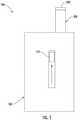
- Figure 1illustrates a front view of an aerosol delivery device 100
- Figure 2illustrates a modified sectional view through the aerosol delivery device, according to an example implementation of the present disclosure
- the aerosol delivery devicemay comprise a housing 102 and a cartridge 200.
- the cartridgemay be moveable with respect to at least a portion of, or an entirety of, the housing.
- the cartridgemay be moveable relative to at least a portion of the housing between an extended configuration illustrated in Figure 1 , and a retracted configuration illustrated in Figure 2 . Details with respect to the mechanisms and manners associated with movement of the cartridge relative to the housing are described hereinafter.
- one or both of the housing 102 or the cartridge 200 of the aerosol delivery device 100may be referred to as being disposable or as being reusable.
- the aerosol delivery devicemay include various other components disposed within the housing or cartridge or otherwise coupled thereto. These components may be distributed between the housing and the cartridge in any of various manners.
- the housingmay include a replaceable battery or a rechargeable battery and thus may be combined with any type of recharging technology, including connection to a typical alternating current electrical outlet, connection to a car charger (i.e., a cigarette lighter receptacle), connection to a computer, such as through a universal serial bus (USB) cable or connector, wireless connection to a Radio Frequency (RF), wireless connection to induction-based charging pads, or connection to a photovoltaic cell (sometimes referred to as a solar cell) or solar panel of solar cells.
- the cartridgemay comprise a single-use cartridge, as disclosed in U.S. Pat. No. 8,910,639 to Chang et al. , which is incorporated herein by reference in its entirety. Accordingly, it should be understood that the described implementations are provided for example purposes only.
- the housing 102 and cartridge 200 forming the aerosol delivery device 100may be permanently coupled to one another.
- aerosol delivery devicesthat may be configured to be disposable and/or which may include first and second outer bodies that are configured for permanent coupling are disclosed in U.S. Pat. Pub. No. 2015/0216232 to Bless et al. , which is incorporated herein by reference in its entirety.
- the housing and cartridgemay be configured in a single-piece, non-detachable form and may incorporate the components, aspects, and features disclosed herein.
- the housing and cartridgemay be configured to be separable such that, for example, the cartridge may be refilled or replaced.
- the aerosol delivery device 100includes a power source 104 positioned within the housing 102.
- the power sourcemay include, for example, a battery (single-use or rechargeable), supercapacitor or the like.
- a connector 106may be moveably attached to the housing.
- the cartridge 200may be engaged with the connector so as to be moveable relative to at least a portion of the housing. In some implementations, the cartridge may be removably engaged with the connector and replaceable.
- the aerosol delivery device 100may include a control component 108 received therein.
- the control componentmay be configured to direct electrical power from the power source 104 to the cartridge 200 to heat aerosol precursor composition retained in the cartridge to produce a vapor, which may occur during a user draw on a mouthpiece of the cartridge.
- the control componentincludes a number of electronic components, and in some examples may be formed of a printed circuit board (PCB) that supports and electrically connects the electronic components. Examples of suitable electronic components include a microprocessor or processor core, an integrated circuit (IC), a memory, and the like.
- the control componentmay include a microcontroller with an integrated processor core and memory, and which may further include one or more integrated input/output peripherals.
- the cartridge 200may be moveable relative to the housing 102.
- the aerosol delivery device 100may further comprise an actuator 110.
- the actuatormay be coupled to the connector 106. Thereby, the actuator may be operatively engaged with the cartridge and configured to move the cartridge between the extended configuration and the retracted configuration.
- Figure 3illustrates a more particular example of the cartridge 200 of FIGS. 1 and 2 .
- the cartridgemay comprise a base shipping plug 202, a base 204, a control component terminal 206, an electronic control component 208, a flow tube 210, an atomizer 212, a reservoir 214, an outer body 216, a label 218, the mouthpiece 220, and a mouthpiece shipping plug 222 according to an example implementation of the present disclosure.
- the mouthpiece 220may be exposed when the cartridge 200 is in the extended configuration.
- the mouthpiecemay be positioned outside of the housing 102 when the cartridge is in the extended configuration such that a user may engage the mouthpiece with his or her lips.
- the extended configuration of the cartridgeis a configuration in which the aerosol delivery device 100 is configured to receive a draw on the mouthpiece such that the aerosol delivery device may produce and deliver an aerosol to a user in the manner described above.
- the mouthpiece 220in the retracted configuration is relatively closer to the housing 102 than in the extended configuration of Figure 1 .
- the mouthpiecemay be flush with respect to the housing.
- an outer surface of the mouthpiecemay substantially align with an outer surface of the housing.
- the mouthpiecemay be recessed with respect to the housing.
- a gapmay be provided between the outer surface of the mouthpiece and the outer surface of the housing.
- the base 204may be coupled to a first end of the outer body 216 and the mouthpiece 220 may be coupled to an opposing second end of the outer body to at least partially enclose the remaining components of the cartridge 200 therein, with the exception of the label 218, the mouthpiece shipping plug 222, and the base shipping plug 202.
- the basemay be configured to engage an associated device including a power source 104.
- the basemay comprise anti-rotation features that substantially prevent relative rotation between the cartridge and associated device including the power source.
- the base shipping plugmay be configured to engage and protect the base prior to use of the cartridge.
- the mouthpiece shipping plugmay be configured to engage and protect the mouthpiece prior to use of the cartridge.
- the control component terminal 206, the electronic control component 208, the flow tube 210, the atomizer 212, and the reservoir substrate 214may be retained within the outer body 216.
- the label 218may at least partially surround the outer body and include information such as a product identifier thereon.
- the atomizer 212may comprise a first heating terminal 234a and a second heating terminal 234b, a liquid transport element 238 and a heating element 240.
- a valvemay be positioned between the reservoir and the heating element, and configured to control an amount of aerosol precursor composition passed or delivered from the reservoir to the heating element.
- the reservoir 214may be a container or can be a fibrous reservoir, as presently described.
- the reservoirmay comprise one or more layers of nonwoven fibers substantially formed into the shape of a tube encircling the interior of the cartridge 200.
- An aerosol precursor compositioncan be retained in the reservoir. Liquid components, for example, can be sorptively retained by the reservoir.
- the reservoircan be in fluid connection with the liquid transport element 238 adapted to wick or otherwise transport an aerosol precursor composition stored in the reservoir housing to the heating element 240.
- the liquid transport elementcan transport the aerosol precursor composition stored in the reservoir via capillary action to the heating element that is in the form of a metal wire coil in this example. As such, the heating element is in a heating arrangement with the liquid transport element.
- Example implementations of reservoirs and transport elements useful in aerosol delivery devices according to the present disclosureare further described below, and such reservoirs and/or transport elements can be incorporated into devices such as illustrated in Figure 3 as described herein.
- specific combinations of heating members and transport elements as further described belowmay be incorporated into devices such as illustrated in Figure 3 as described herein.
- the heating element in these examplesmay be resistive heating element such as a wire coil.
- Example materials from which the wire coil may be formedinclude titanium (Ti), platinum (Pt), nichrome (NiCrFe) Kanthal (FeCrAl), Nichrome, Molybdenum disilicide (MoSi 2 ), molybdenum silicide (MoSi), Molybdenum disilicide doped with Aluminum (Mo(Si,Al) 2 ), graphite and graphite-based materials (e.g., carbon-based foams and yarns), silver palladium (AgPd) conductive inks, boron doped silica, and ceramics (e.g., positive or negative temperature coefficient ceramics).
- Example implementations of heating elements or heating members useful in aerosol delivery devices according to the present disclosureare further described below, and can be incorporated into devices such as illustrated in Figure 3 as described
- the cartridge 200may include a flow director defining a non-tubular configuration, an electronics compartment sealed with respect to a reservoir compartment, and/or any of the various other features and components disclosed therein. Accordingly, it should be understood that the particular implementation of the cartridge described herein is provided for example purposes only. In this regard, the cartridge is schematically illustrated in Figure 2 as including only the outer body 216, the mouthpiece 220, the atomizer 212, the reservoir 214, and the base 204, in light of the various alternate and additional components that may be included therein.
- One or more components of the cartridge 200may be configured to form an electrical connection with the connector 106.
- the first heating terminal 234a and the second heating terminal 234be.g., positive and negative terminals
- the electronic control component 208See Figure 3
- the control component 108may form an electrical connection with the connector through the control component terminal 206 ( See Figure 3 ).
- Components within the housing 102e.g., the control component 108
- the connection between the connector and the cartridgemay not be electrical.
- connection between the connector and the cartridgemay be purely mechanical.
- atomizationmay occur outside of the cartridge or atomization may occur via other methods not requiring electrical connections between the cartridge and the housing such as via piezoelectric or radio frequency atomization.
- the power sourcemay be positioned in the cartridge such that electrical connection with connector is not required.
- the heating element 240 of the atomizer 212is activated to vaporize components of the aerosol precursor composition.
- Drawing upon the mouthpiece 220 of the aerosol delivery devicecauses ambient air to enter and pass through an opening in the connector 106 or in the cartridge 200.
- the drawn aircombines with the formed vapor to form an aerosol.
- the aerosolis whisked, aspirated or otherwise drawn away from the heating element and out the opening in the mouthpiece of the aerosol delivery device.
- the flow of airmay be received through other parts of the aerosol delivery device in other implementations.
- the cartridgemay include the flow tube 210.
- the flow tubemay be configured to direct the flow of air to the heating element.
- a sensor in the aerosol delivery device 100may detect the flow of air throughout the aerosol delivery device.
- the control component 108may direct current to the heating element 240 through a circuit including the first heating terminal 234a and the second heating terminal 234b.
- the heating elementmay vaporize the aerosol precursor composition directed to an aerosolization zone from the reservoir 214 by the liquid transport element 238.
- the mouthpiece 220may allow passage of aerosol (i.e., the components of the aerosol precursor composition in an inhalable form) therethrough to a consumer drawing thereon.
- the aerosol delivery devicemay further comprise an indicator 116.
- the indicatormay comprise a light transmitter (e.g., plastic or glass, which may be tinted a desired color).
- the indicatormay include a light emitter, which may comprise an incandescent bulb or light emitting diode (LED). Thereby, the light emitter may illuminate the light transmitter, which may direct the light outwardly therethrough to output a status of the aerosol delivery device.
- the indicator 116may flash or otherwise illuminate to indicate a remaining or used portion of the capacity of the power source 104 or the reservoir 214.
- a relatively large number of flashes of the indicator 116 upon actuation of an input mechanismmay correspond to a relatively large remaining capacity of the power source or the reservoir.
- the input mechanismmay comprise a pushbutton or other switch configured to receive an input from a user.
- the aerosol delivery devicemay produce an output corresponding to a status of the aerosol delivery device.
- the aerosol delivery device 100may output sound, vibration, or light.
- a relatively small number of flashes of the indicator upon actuation of the input mechanismmay correspond to a relatively small remaining capacity of the power source or the reservoir.
- the indicator and/or other output mechanismsmay be employed to output various other information and/or output information in various other manners. Examples of other information that may be outputted include error messages, operational modes, historical usage information, etc.
- the aerosol delivery device 100may include a display.
- the displaymay be provided in addition to, or as an alternate for, the indicator 116.
- the displaymay be configured to output various information including information regarding a status of the aerosol delivery device, information unrelated to the status of the aerosol delivery device (e.g., the present time), and/or non-informative graphics (e.g., graphics provided for user entertainment purposes).
- the displaymay be configured to output any or all of the information described above (e.g., a remaining or used portion of the capacity of the power source 104 or the reservoir 214 ) in any form such as graphical form and/or a numerical form.
- operation or the displaymay be controlled by the input mechanism.
- the displaymay be a touchscreen and thus may be configured for user input (e.g. adjustment of power supplied to the heating element(s).
- the displaymay provide icons, menus, or the like configured to allow a user to make control selections related to the functioning of the aerosol delivery device, check a specific status of the device, or the like.
- the displayis illustrated as encompassing only a relatively small portion of the aerosol delivery device, it is understood that the display may cover a significantly greater portion of the aerosol delivery device.
- an aerosol delivery device 100can be chosen from components described in the art and commercially available.
- Examples of batteries that can be used according to the disclosureare described in U.S. Pat. App. Pub. No. 2010/0028766 to Peckerar et al. , which is incorporated herein by reference in its entirety.
- the aerosol delivery device 100can incorporate the flow sensor or another sensor or detector for control of supply of electric power to the heating element 240 when aerosol generation is desired (e.g., upon draw during use).
- a manner or method of turning off the power supply to the heating element when the aerosol delivery device is not be drawn upon during use, and for turning on the power supply to actuate or trigger the generation of heat by the heating element during draware described in U.S. Pat. No. 5,261,424 to Sprinkel, Jr. , U.S. Pat. No. 5,372,148 to McCafferty et al. , and PCT Pat. App. Pub. No. WO 2010/003480 to Flick , all of which are incorporated herein by reference in their entireties.
- the aerosol delivery device 100most preferably incorporates the control component 108 or another control mechanism for controlling the amount of electric power to the heating element 240 during draw.
- Representative types of electronic components, structure and configuration thereof, features thereof, and general methods of operation thereof,are described in U.S. Pat. No. 4,735,217 to Gerth et al. , U.S. Pat. No. 4,947,874 to Brooks et al. , U.S. Pat. No. 5,372,148 to McCafferty et al. , U.S. Pat. No. 6,040,560 to Fleischhauer et al. , U.S. Pat. No. 7,040,314 to Nguyen et al. , U.S. Pat. No.
- the aerosol precursor compositionalso referred to as a vapor precursor composition, may comprise a variety of components including, by way of example, a polyhydric alcohol (e.g., glycerin, propylene glycol or a mixture thereof), nicotine, tobacco, tobacco extract and/or flavorants.
- a polyhydric alcohole.g., glycerin, propylene glycol or a mixture thereof
- nicotinetobacco, tobacco extract and/or flavorants.
- Representative types of aerosol precursor components and formulationsalso are set forth and characterized in U.S. Pat. No. 7,217,320 to Robinson et al. and U.S. Pat. Pub. Nos. 2013/0008457 to Zheng et al. ; 2013/0213417 to Chong et al. ; 2014/0060554 to Collett et al. ; 2015/0020823 to Lipowicz et al.
- aerosol precursorsthat may be employed include the aerosol precursors that have been incorporated in the VUSE ® product by R. J. Reynolds Vapor Company, the BLU TM product by Imperial Tobacco Group PLC, the MISTIC MENTHOL product by Mistic Ecigs, and the VYPE product by CN Creative Ltd. Also desirable are the so-called "smoke juices" for electronic cigarettes that have been available from Johnson Creek Enterprises LLC.
- LEDs and related componentssuch as LEDs and related components, auditory elements (e.g., speakers), vibratory elements (e.g., vibration motors) and the like.
- auditory elementse.g., speakers
- vibratory elementse.g., vibration motors
- suitable LED componentsand the configurations and uses thereof, are described in U.S. Pat. No. 5,154,192 to Sprinkel et al. , U.S. Pat. No. 8,499,766 to Newton , U.S. Pat. No. 8,539,959 to Scatterday , and U.S. Pat. Pub. No. 2015/0216233 to Sears et al. , all of which are incorporated herein by reference in their entireties.
- the aerosol delivery device 100may include a power source 104.
- this power source or another, secondary power sourcemay be detachably coupled to the control body 102.
- Figure 4illustrates an example of a suitable aerosol delivery device 400 (one example of which may be aerosol delivery device 100 of Figures 1 and 2 ).
- the aerosol delivery devicemay include a control body 402 coupled or coupleable with a cartridge 404 that may correspond respectively to the control body 102 and cartridge 104 of Figures 1 and 2 .
- the cartridgemay be equipped with a heating element and may contain an aerosol precursor composition.
- the control bodymay be coupled or coupleable with the cartridge to form the aerosol delivery device in which the heating element may be configured to activate and vaporize components of the aerosol precursor composition.
- Figure 4illustrates the aerosol delivery device 400 having a detachable power source 406.
- the control body 402may comprise a housing 408, and the power source may be detachably coupled to an outer surface 410 of the housing.
- a control componente.g., control component 108
- the control component in the active modemay be configured to direct power from the power source to the heating element of the cartridge to activate and vaporize components of the aerosol precursor composition contained within the cartridge.
- the power source 406may be or include one or more lithium-ion batteries or capacitors, and the control component of the control body 402 may be configured to direct power from the from the one or more lithium-ion batteries or capacitors to the heating element of the cartridge 404 to activate and vaporize components of the aerosol precursor composition contained within the cartridge.
- the power sourcemay include a lithium-ion battery power pack which may be can-shaped or in flat format, as shown in Figure 4 .
- the power source 406is a secondary power source
- the control body 402further comprises a primary power source (e.g., power source 104 ) within the housing 408.
- the control component being configured to direct power from the power sourcemay include being the control component being configured to switchably direct power from the primary power source or secondary power source.
- the control component being configured to switchably direct powermay include the control component being configured to direct power from the primary power source, and switch to the secondary power source only after the primary power source has discharged by at least a threshold amount.
- the power sourcemay be implemented as a supplemental power source, to be utilized when the primary power source has been fully discharged, for example.
- the power sourcemay be a secondary power source in some example implementations, in other examples, the power source may be utilized as the sole power supply of the aerosol delivery device 400.
- the power source 406may be coupleable with a charging component configured to charge the power source.
- the power sourcemay be coupleable with the charging component and chargeable via the charging component while the power source is detached from the outer surface 410 of the housing 408.
- the power sourcemay be coupleable with the charging component and chargeable via the charging component while the power source coupled with the outer surface of the housing.
- suitable charging componentsinclude inductive charging component (e.g., wireless charging pad), wireless charging from an RF transmitter, charging stands, USB chargers (e.g., micro-usb charger), and photovoltaic systems (e.g., solar cells).
- the power source 406 being coupleable with the charging componentmay include the power source being inductively coupleable with the charging component in which the charging component may be configured to wirelessly charge the power source.
- the power source and the control body 402may be designed to include a form factor that provides a large surface area, with respect to the power source, for induction-based charging.
- the power source 406 being coupleable with the charging componentmay include the power source being coupleable to an RF transmitter in which the charging component may be configured to wirelessly charge the power source.
- the power source being coupleable with the RF transmittermay include the primary power source and secondary power source being configured to wirelessly receive RF waves as a means of charging the primary power source, secondary power source, or simultaneously both.
- the power source being coupleable with the charging componentmay include the power source being coupleable with a charging stand in which the charging stand may be configured to charge the power source with the power source coupled to the outer surface 410 of the housing 408.
- the power sourcemay also be coupleable with a charging stand in which the charging stand may be configured to charge the power source with the power source detached from the outer surface of the housing.
- the charging standmay be or include a docking station configured to individually and/or collectively charge the power source or control body 402.
- the control bodymay further comprise a universal serial bus (USB) port coupled to the housing 408 of the control body.
- the power source 406may be detachably, electrically coupleable to the USB port.
- the power source being coupleable with the changing standmay include the USB port being coupleable with a USB charging interface of the charging stand.
- the power source 406is a secondary power source
- the control body 402further comprises a primary power source (e.g., power source 104 ) within the housing 408.
- the control component being configured to direct power from the power sourcemay include the control component being configured to direct power from the primary power source and secondary power source.
- the power source being coupleable with the changing standmay include the primary power source and secondary power source being coupleable with the charging stand in which the charging stand may be configured to simultaneously charge the primary power source and secondary power source.
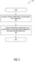
- FIG. 5illustrates various operations in a method 500 of controlling an aerosol delivery device according to an example implementation of the present disclosure.
- the aerosol delivery devicemay include a control body coupled with a cartridge that is equipped with a heating element and contains an aerosol precursor composition.
- the heating elementmay be configured to activate and vaporize components of the aerosol precursor composition.
- the methodmay include detachably coupling a power source to an outer surface of the control body.
- the methodmay also include directing power from the power source to the heating element to activate and vaporize components of the aerosol precursor composition.
Landscapes
- Engineering & Computer Science (AREA)
- Health & Medical Sciences (AREA)
- Computer Networks & Wireless Communication (AREA)
- Power Engineering (AREA)
- General Health & Medical Sciences (AREA)
- Life Sciences & Earth Sciences (AREA)
- Hematology (AREA)
- Animal Behavior & Ethology (AREA)
- Heart & Thoracic Surgery (AREA)
- Public Health (AREA)
- Veterinary Medicine (AREA)
- Biomedical Technology (AREA)
- Anesthesiology (AREA)
- Human Computer Interaction (AREA)
- Chemical & Material Sciences (AREA)
- Chemical Kinetics & Catalysis (AREA)
- General Chemical & Material Sciences (AREA)
- Manufacturing & Machinery (AREA)
- Electrochemistry (AREA)
- Charge And Discharge Circuits For Batteries Or The Like (AREA)
- Containers And Packaging Bodies Having A Special Means To Remove Contents (AREA)
- Catching Or Destruction (AREA)
- Nozzles (AREA)
- Toxicology (AREA)
- Feeding, Discharge, Calcimining, Fusing, And Gas-Generation Devices (AREA)
Abstract
Description
- The present disclosure relates to aerosol delivery devices such as smoking articles that may utilize electrically generated heat for the production of aerosol (e.g., smoking articles commonly referred to as electronic cigarettes). The smoking articles may be configured to heat the aerosol precursor, which may incorporate materials that may be made or derived from tobacco or otherwise incorporate tobacco, the precursor being capable of forming an inhalable substance for human consumption.
- Many smoking devices have been proposed through the years as improvements upon, or alternatives to, smoking products that require combusting tobacco for use. Many of those devices purportedly have been designed to provide the sensations associated with cigarette, cigar or pipe smoking, but without delivering considerable quantities of incomplete combustion and pyrolysis products that result from the burning of tobacco. To this end, there have been proposed numerous smoking products, flavor generators and medicinal inhalers that utilize electrical energy to vaporize or heat a volatile material, or attempt to provide the sensations of cigarette, cigar or pipe smoking without burning tobacco to a significant degree. See, for example, the various alternative smoking articles, aerosol delivery devices and heat generating sources set forth in the background art described in
U.S. Pat. Nos. 7,726,320 to Robinson et al . and8,881,737 to Collett et al. , which are incorporated herein by reference. See also, for example, the various types of smoking articles, aerosol delivery devices and electrically-powered heat generating sources referenced by brand name and commercial source inU.S. Pat. Pub. No. 2015/0216232 to Bless et al. , which is incorporated herein by reference. Additionally, various types of electrically powered aerosol and vapor delivery devices also have been proposed inU.S. Pat. Pub. Nos. 2014/0096781 to Sears et al. and2014/0283859 to Minskoff et al. , as well asU.S. Pat. App. Ser. Nos. 14/282,768 to Sears et al., filed May 20, 2014 14/286,552 to Brinkley et al., filed May 23, 2014 14/327,776 to Ampolini et al., filed July 10, 2014 14/465,167 to Worm et al., filed August 21, 2014 - The present disclosure relates to aerosol delivery devices, methods of forming such devices, and elements of such devices. The present disclosure thus includes, without limitation, the following example implementations.
- Example Implementation 1: A control body coupled or coupleable with a cartridge that is equipped with a heating element and contains an aerosol precursor composition, the control body being coupled or coupleable with the cartridge to form an aerosol delivery device in which the heating element is configured to activate and vaporize components of the aerosol precursor composition, the control body comprising a housing; a power source detachably coupled to an outer surface of the housing; and a control component contained within the housing and configured to operate in an active mode in which the control body is coupled with the cartridge, the control component in the active mode being configured to direct power from the power source to the heating element to activate and vaporize components of the aerosol precursor composition.
- Example Implementation 2: The control body of the preceding or any subsequent example implementation, or any combination thereof, wherein the power source is or includes one or more lithium-ion batteries or capacitors, and wherein the control component being configured to direct power from the power source includes being configured to direct power from the one or more lithium-ion batteries or capacitors.
- Example Implementation 3: The control body of any preceding or any subsequent example implementation, or any combination thereof, wherein the power source is a secondary power source, the control body further comprises a primary power source within the housing, and the control component being configured to direct power from the power source includes being configured to switchably direct power from the primary power source or secondary power source.
- Example Implementation 4: The control body of any preceding or any subsequent example implementation, or any combination thereof, wherein the control component being configured to switchably direct power includes being configured to direct power from the primary power source, and switch to the secondary power source only after the primary power source has discharged by at least a threshold amount.
- Example Implementation 5: The control body of any preceding or any subsequent example implementation, or any combination thereof, wherein the power source is coupleable with a charging component configured to charge the power source, and in at least one instance with the power source detached from the outer surface of the housing.
- Example Implementation 6: The control body of any preceding or any subsequent example implementation, or any combination thereof, wherein the power source is coupleable with a charging component configured to charge the power source, and in at least one instance with the power source coupled to the outer surface of the housing.
- Example Implementation 7: The control body of any preceding or any subsequent example implementation, or any combination thereof, wherein the power source being coupleable with the charging component includes being inductively coupleable with the charging component configured to wirelessly charge the power source.
- Example Implementation 8: The control body of any preceding or any subsequent example implementation, or any combination thereof, wherein the power source being coupleable with a radio frequency (RF) transmitter configured to charge the power source with the power source coupled to the outer surface of the housing.
- Example Implementation 9: The control body of any preceding or any subsequent example implementation, or any combination thereof, wherein the power source being coupleable with the charging component includes being coupleable with a charging stand configured to charge the power source with the power source coupled to the outer surface of the housing.
- Example Implementation 10: The control body of any preceding or any subsequent example implementation, or any combination thereof, wherein the control body further comprises a universal serial bus (USB) port coupled to the housing, the power source being detachably, electrically coupleable to the USB port, and the wherein power source being coupleable with the changing stand includes the USB port being coupleable with a USB charging interface of the charging stand.
- Example Implementation 11: The control body of any preceding or any subsequent example implementation, or any combination thereof, wherein the power source is a secondary power source, the control body further comprises a primary power source within the housing, and the control component being configured to direct power from the power source includes being configured to direct power from the primary power source and secondary power source, and wherein the power source being coupleable with the charging stand includes the primary power source and secondary power source being coupleable with the charging stand configured to simultaneously charge the primary power source and secondary power source.
- Example Implementation 12: A method of controlling an aerosol delivery device including a control body coupled with a cartridge that is equipped with a heating element and contains an aerosol precursor composition, the heating element being configured to activate and vaporize components of the aerosol precursor composition, the method comprising detachably coupling a power source to an outer surface of the control body; and directing power from the power source to the heating element to activate and vaporize components of the aerosol precursor composition.
- Example Implementation 13: The method of the preceding or any subsequent example implementation, or any combination thereof, wherein the power source is or includes one or more lithium-ion batteries or capacitors, and directing power from the power source includes directing power from the one-or-more lithium-ion batteries or capacitors
- Example Implementation 14: The method of any preceding or any subsequent example implementation, or any combination thereof, wherein the power source is a secondary power source, the control body comprises a primary power source, and directing power from the power source includes switchably directing power from the primary power source or secondary power source.
- Example Implementation 15: The method of any preceding or any subsequent example implementation, or any combination thereof, wherein switchably directing power includes directing power from the primary power source, and switching to the secondary power source only after the primary power source has discharged by at least a threshold amount.
- Example Implementation 16: The method of any preceding or any subsequent example implementation, or any combination thereof, wherein the method further comprises coupling the power source with a charging component configured to charge the power source, and in at least one instance with the power source detached from the outer surface of the housing.
- Example Implementation 17: The method of any preceding or any subsequent example implementation, or any combination thereof, wherein the method further comprises coupling the power source with a charging component configured to charge the power source, and in at least one instance with the power source coupled to the outer surface of the control body.
- Example Implementation 18: The method of any preceding or any subsequent example implementation, or any combination thereof, wherein coupling the power source with the charging component includes inductively coupling the power source with the charging component configured to wirelessly charge the power source.
- Example Implementation 19: The method of any preceding or any subsequent example implementation, or any combination thereof, wherein coupling the power source with the charging component includes wirelessly coupling the power source with a radio frequency (RF) transmitter configured to wirelessly charge the power source.
- Example Implementation 20: The method of any preceding or any subsequent example implementation, or any combination thereof, wherein coupling the power source with the charging component includes coupling the power source with a charging stand configured to charge the power source with the power source coupled to the outer surface of the control body.
- Example Implementation 21: The method of any preceding or any subsequent example implementation, or any combination thereof, wherein a universal serial bus (USB) port is coupled to the control body, and the power source is detachably, electrically coupleable to the USB port, and wherein coupling the power source with the changing stand includes coupling the USB port with a USB charging interface of the charging stand.
- Example Implementation 22: The method of any preceding or any subsequent example implementation, or any combination thereof, wherein the power source is a secondary power source, the control body comprises a primary power source, and directing power from the power source includes directing power from the primary power source and secondary power source, and wherein coupling the power source with the charging stand includes coupling the primary power source and secondary power source with the charging stand configured to simultaneously charge the primary power source and secondary power source.
- These and other features, aspects, and advantages of the present disclosure will be apparent from a reading of the following detailed description together with the accompanying drawings, which are briefly described below. The present disclosure includes any combination of two, three, four or more features or elements set forth in this disclosure, regardless of whether such features or elements are expressly combined or otherwise recited in a specific example implementation described herein. This disclosure is intended to be read holistically such that any separable features or elements of the disclosure, in any of its aspects and example implementations, should be viewed as combinable, unless the context of the disclosure clearly dictates otherwise.
- It will therefore be appreciated that this Brief Summary is provided merely for purposes of summarizing some example implementations so as to provide a basic understanding of some aspects of the disclosure. Accordingly, it will be appreciated that the above described example implementations are merely examples and should not be construed to narrow the scope or spirit of the disclosure in any way. Other example implementations, aspects and advantages will become apparent from the following detailed description taken in conjunction with the accompanying drawings which illustrate, by way of example, the principles of some described example implementations.
- Having thus described the disclosure in the foregoing general terms, reference will now be made to the accompanying drawings, which are not necessarily drawn to scale, and wherein:
Figure 1 illustrates a front view of an aerosol delivery device including a housing having a cartridge therein, according to an example implementation of the present disclosure;Figure 2 schematically illustrates a sectional view through the aerosol delivery device, according to an example implementation;Figure 3 illustrates an exploded view of a cartridge suitable for use in the aerosol delivery device, according to an example implementation;Figure 4 illustrates an aerosol delivery device having a detachable power source according to an example implementation of the present disclosure; andFigure 5 illustrates various operations in a method for controlling an aerosol delivery device, according to an example implementation of the present disclosure.- The present disclosure will now be described more fully hereinafter with reference to example implementations thereof. These example implementations are described so that this disclosure will be thorough and complete, and will fully convey the scope of the disclosure to those skilled in the art. Indeed, the disclosure may be embodied in many different forms and should not be construed as limited to the implementations set forth herein; rather, these implementations are provided so that this disclosure will satisfy applicable legal requirements. As used in the specification and the appended claims, the singular forms "a," "an," "the" and the like include plural referents unless the context clearly dictates otherwise.
- As described hereinafter, example implementations of the present disclosure relate to aerosol delivery systems. Aerosol delivery systems according to the present disclosure use electrical energy to heat a material (preferably without combusting the material to any significant degree) to form an inhalable substance; and components of such systems have the form of articles most preferably are sufficiently compact to be considered hand-held devices. That is, use of components of preferred aerosol delivery systems does not result in the production of smoke in the sense that aerosol results principally from byproducts of combustion or pyrolysis of tobacco, but rather, use of those preferred systems results in the production of vapors resulting from volatilization or vaporization of certain components incorporated therein. In some example implementations, components of aerosol delivery systems may be characterized as electronic cigarettes, and those electronic cigarettes most preferably incorporate tobacco and/or components derived from tobacco, and hence deliver tobacco derived components in aerosol form.
- Aerosol generating pieces of certain preferred aerosol delivery systems may provide many of the sensations (e.g., inhalation and exhalation rituals, types of tastes or flavors, organoleptic effects, physical feel, use rituals, visual cues such as those provided by visible aerosol, and the like) of smoking a cigarette, cigar or pipe that is employed by lighting and burning tobacco (and hence inhaling tobacco smoke), without any substantial degree of combustion of any component thereof. For example, the user of an aerosol generating piece of the present disclosure can hold and use that piece much like a smoker employs a traditional type of smoking article, draw on one end of that piece for inhalation of aerosol produced by that piece, take or draw puffs at selected intervals of time, and the like.
- Aerosol delivery systems of the present disclosure also can be characterized as being vapor-producing articles or medicament delivery articles. Thus, such articles or devices can be adapted so as to provide one or more substances (e.g., flavors and/or pharmaceutical active ingredients) in an inhalable form or state. For example, inhalable substances can be substantially in the form of a vapor (i.e., a substance that is in the gas phase at a temperature lower than its critical point). Alternatively, inhalable substances can be in the form of an aerosol (i.e., a suspension of fine solid particles or liquid droplets in a gas). For purposes of simplicity, the term "aerosol" as used herein is meant to include vapors, gases and aerosols of a form or type suitable for human inhalation, whether or not visible, and whether or not of a form that might be considered to be smoke-like.
- Aerosol delivery systems of the present disclosure generally include a number of components provided within an outer body or shell, which may be referred to as a housing. The overall design of the outer body or shell can vary, and the format or configuration of the outer body that can define the overall size and shape of the aerosol delivery device can vary. Aerosol delivery devices are often configured in a manner that mimics aspects of certain traditional smoking devices such as cigarettes or cigars. In this regard, aerosol delivery devices typically define a substantially cylindrical configuration. Typically, an elongated body resembling the shape of a cigarette or cigar can be a formed from a single, unitary housing or the elongated housing can be formed of two or more separable bodies. For example, an aerosol delivery device can comprise an elongated shell or body that can be substantially tubular in shape and, as such, resemble the shape of a conventional cigarette or cigar. The aerosol delivery device may alternatively define an ergonomic shape configured to comfortably fit within a user's hand. The shape of the housing, however, is not limited and may be any shape that accommodates the various elements as described herein. In some implementations, the housing of the aerosol delivery device may be expressly non-cylindrical. Aerosol delivery devices often include a control body and a cartridge which attach in an end-to-end relationship to define the substantially cylindrical configuration.
- While such configurations may provide a look and feel that is similar to traditional smoking articles, these configurations may suffer from certain detriments. For example, cylindrically-configured aerosol delivery devices may not define attachment points usable to retain the aerosol delivery device in a desired position when not in use. Further, the cylindrical configuration may result in the mouthpiece being exposed to the surrounding environment and therefore susceptible to contamination. Accordingly, it may be desirable to provide aerosol delivery devices in configurations that differ from shapes associated with traditional smoking articles.
- In one example, all of the components of the aerosol delivery device are contained within one housing. Alternatively, an aerosol delivery device can comprise two or more housings that are joined and are separable. For example, an aerosol delivery device can possess at one end a control body comprising a housing containing one or more reusable components (e.g., an accumulator such as a rechargeable battery and/or capacitor, and various electronics for controlling the operation of that article), and at the other end and removably coupleable thereto, an outer body or shell containing a disposable portion (e.g., a disposable flavor-containing cartridge).
- Aerosol delivery systems of the present disclosure most preferably comprise some combination of a power source (i.e., an electrical power source), at least one control component (e.g., means for actuating, controlling, regulating and ceasing power for heat generation, such as by controlling electrical current flow the power source to other components of the article - e.g., a microprocessor, individually or as part of a microcontroller), a heater or heat generation member (e.g., an electrical resistance heating element or other component, which alone or in combination with one or more further elements may be commonly referred to as an "atomizer"), an aerosol precursor composition (e.g., commonly a liquid capable of yielding an aerosol upon application of sufficient heat, such as ingredients commonly referred to as "smoke juice," "e-liquid" and "e-juice"), and a mouthend region or tip for allowing draw upon the aerosol delivery device for aerosol inhalation (e.g., a defined airflow path through the article such that aerosol generated can be withdrawn therefrom upon draw).
- In various examples, an aerosol delivery device can comprise a reservoir configured to retain the aerosol precursor composition. The reservoir particularly can be formed of a porous material (e.g., a fibrous material) and thus may be referred to as a porous substrate (e.g., a fibrous substrate).
- A fibrous substrate useful as a reservoir in an aerosol delivery device can be a woven or nonwoven material formed of a plurality of fibers or filaments and can be formed of one or both of natural fibers and synthetic fibers. For example, a fibrous substrate may comprise a fiberglass material a cellulose acetate material, a carbon material, a polyethylene terephthalate (PET) material, a rayon material, or an organic cotton material can be used. A reservoir may be substantially in the form of a container and may include a fibrous material included therein.
- In some implementations, the aerosol delivery device can include an indicator, which may comprise one or more light emitting diodes or a graphical user interface via a display. The indicator can be in communication with the control component through a connector circuit and illuminate, for example, during a user draw on the mouthend as detected by the flow sensor.
- More specific formats, configurations and arrangements of components within the aerosol delivery systems of the present disclosure will be evident in light of the further disclosure provided hereinafter. Additionally, the selection and arrangement of various aerosol delivery system components can be appreciated upon consideration of the commercially available electronic aerosol delivery devices, such as those representative products referenced in background art section of the present disclosure.
Figure 1 illustrates a front view of anaerosol delivery device 100, andFigure 2 illustrates a modified sectional view through the aerosol delivery device, according to an example implementation of the present disclosure. As illustrated, the aerosol delivery device may comprise ahousing 102 and acartridge 200. The cartridge may be moveable with respect to at least a portion of, or an entirety of, the housing. In particular, the cartridge may be moveable relative to at least a portion of the housing between an extended configuration illustrated inFigure 1 , and a retracted configuration illustrated inFigure 2 . Details with respect to the mechanisms and manners associated with movement of the cartridge relative to the housing are described hereinafter.- In some example implementations, one or both of the
housing 102 or thecartridge 200 of theaerosol delivery device 100 may be referred to as being disposable or as being reusable. The aerosol delivery device may include various other components disposed within the housing or cartridge or otherwise coupled thereto. These components may be distributed between the housing and the cartridge in any of various manners. For example, the housing may include a replaceable battery or a rechargeable battery and thus may be combined with any type of recharging technology, including connection to a typical alternating current electrical outlet, connection to a car charger (i.e., a cigarette lighter receptacle), connection to a computer, such as through a universal serial bus (USB) cable or connector, wireless connection to a Radio Frequency (RF), wireless connection to induction-based charging pads, or connection to a photovoltaic cell (sometimes referred to as a solar cell) or solar panel of solar cells. Further, in some example implementations, the cartridge may comprise a single-use cartridge, as disclosed inU.S. Pat. No. 8,910,639 to Chang et al. , which is incorporated herein by reference in its entirety. Accordingly, it should be understood that the described implementations are provided for example purposes only. - In one example implementation, the
housing 102 andcartridge 200 forming theaerosol delivery device 100 may be permanently coupled to one another. Examples of aerosol delivery devices that may be configured to be disposable and/or which may include first and second outer bodies that are configured for permanent coupling are disclosed inU.S. Pat. Pub. No. 2015/0216232 to Bless et al. , which is incorporated herein by reference in its entirety. In another example implementation, the housing and cartridge may be configured in a single-piece, non-detachable form and may incorporate the components, aspects, and features disclosed herein. However, in another example implementation, the housing and cartridge may be configured to be separable such that, for example, the cartridge may be refilled or replaced. - By way of example, in the illustrated implementation of
Figure 2 , theaerosol delivery device 100 includes apower source 104 positioned within thehousing 102. The power source may include, for example, a battery (single-use or rechargeable), supercapacitor or the like. Further, a connector106 may be moveably attached to the housing. Thecartridge 200 may be engaged with the connector so as to be moveable relative to at least a portion of the housing. In some implementations, the cartridge may be removably engaged with the connector and replaceable. - The
aerosol delivery device 100 may include acontrol component 108 received therein. The control component may be configured to direct electrical power from thepower source 104 to thecartridge 200 to heat aerosol precursor composition retained in the cartridge to produce a vapor, which may occur during a user draw on a mouthpiece of the cartridge. The control component includes a number of electronic components, and in some examples may be formed of a printed circuit board (PCB) that supports and electrically connects the electronic components. Examples of suitable electronic components include a microprocessor or processor core, an integrated circuit (IC), a memory, and the like. In some examples, the control component may include a microcontroller with an integrated processor core and memory, and which may further include one or more integrated input/output peripherals. - As noted above, the
cartridge 200 may be moveable relative to thehousing 102. In this regard, theaerosol delivery device 100 may further comprise anactuator 110. In particular, the actuator may be coupled to the connector106. Thereby, the actuator may be operatively engaged with the cartridge and configured to move the cartridge between the extended configuration and the retracted configuration. Figure 3 illustrates a more particular example of thecartridge 200 ofFIGS. 1 and2 . As illustrated, the cartridge may comprise abase shipping plug 202, abase 204, acontrol component terminal 206, anelectronic control component 208, aflow tube 210, anatomizer 212, areservoir 214, anouter body 216, alabel 218, themouthpiece 220, and amouthpiece shipping plug 222 according to an example implementation of the present disclosure.- As illustrated in
Figure 1 , themouthpiece 220 may be exposed when thecartridge 200 is in the extended configuration. In other words the mouthpiece may be positioned outside of thehousing 102 when the cartridge is in the extended configuration such that a user may engage the mouthpiece with his or her lips. Thus, the extended configuration of the cartridge is a configuration in which theaerosol delivery device 100 is configured to receive a draw on the mouthpiece such that the aerosol delivery device may produce and deliver an aerosol to a user in the manner described above. - Conversely, as illustrated in
Figure 2 , in the retracted configuration themouthpiece 220 is relatively closer to thehousing 102 than in the extended configuration ofFigure 1 . In the retracted configuration, the mouthpiece may be flush with respect to the housing. In other words, an outer surface of the mouthpiece may substantially align with an outer surface of the housing. In another implementation the mouthpiece may be recessed with respect to the housing. In other words, a gap may be provided between the outer surface of the mouthpiece and the outer surface of the housing. - The base204 may be coupled to a first end of the
outer body 216 and themouthpiece 220 may be coupled to an opposing second end of the outer body to at least partially enclose the remaining components of thecartridge 200 therein, with the exception of thelabel 218, themouthpiece shipping plug 222, and thebase shipping plug 202. The base may be configured to engage an associated device including apower source 104. In some implementations, the base may comprise anti-rotation features that substantially prevent relative rotation between the cartridge and associated device including the power source. The base shipping plug may be configured to engage and protect the base prior to use of the cartridge. Similarly, the mouthpiece shipping plug may be configured to engage and protect the mouthpiece prior to use of the cartridge. - The
control component terminal 206, theelectronic control component 208, theflow tube 210, theatomizer 212, and thereservoir substrate 214 may be retained within theouter body 216. Thelabel 218 may at least partially surround the outer body and include information such as a product identifier thereon. Theatomizer 212 may comprise a first heating terminal234a and asecond heating terminal 234b, aliquid transport element 238 and aheating element 240. - In some example, a valve may be positioned between the reservoir and the heating element, and configured to control an amount of aerosol precursor composition passed or delivered from the reservoir to the heating element.
- The
reservoir 214 may be a container or can be a fibrous reservoir, as presently described. For example, the reservoir may comprise one or more layers of nonwoven fibers substantially formed into the shape of a tube encircling the interior of thecartridge 200. An aerosol precursor composition can be retained in the reservoir. Liquid components, for example, can be sorptively retained by the reservoir. The reservoir can be in fluid connection with theliquid transport element 238 adapted to wick or otherwise transport an aerosol precursor composition stored in the reservoir housing to theheating element 240. In particular, the liquid transport element can transport the aerosol precursor composition stored in the reservoir via capillary action to the heating element that is in the form of a metal wire coil in this example. As such, the heating element is in a heating arrangement with the liquid transport element. Example implementations of reservoirs and transport elements useful in aerosol delivery devices according to the present disclosure are further described below, and such reservoirs and/or transport elements can be incorporated into devices such as illustrated inFigure 3 as described herein. In particular, specific combinations of heating members and transport elements as further described below may be incorporated into devices such as illustrated inFigure 3 as described herein. - Various examples of materials configured to produce heat when electrical current is applied therethrough may be employed to form the
heating element 240. The heating element in these examples may be resistive heating element such as a wire coil. Example materials from which the wire coil may be formed include titanium (Ti), platinum (Pt), nichrome (NiCrFe) Kanthal (FeCrAl), Nichrome, Molybdenum disilicide (MoSi2), molybdenum silicide (MoSi), Molybdenum disilicide doped with Aluminum (Mo(Si,Al)2), graphite and graphite-based materials (e.g., carbon-based foams and yarns), silver palladium (AgPd) conductive inks, boron doped silica, and ceramics (e.g., positive or negative temperature coefficient ceramics). Example implementations of heating elements or heating members useful in aerosol delivery devices according to the present disclosure are further described below, and can be incorporated into devices such as illustrated inFigure 3 as described herein. - The
cartridge 200 may include a flow director defining a non-tubular configuration, an electronics compartment sealed with respect to a reservoir compartment, and/or any of the various other features and components disclosed therein. Accordingly, it should be understood that the particular implementation of the cartridge described herein is provided for example purposes only. In this regard, the cartridge is schematically illustrated inFigure 2 as including only theouter body 216, themouthpiece 220, theatomizer 212, thereservoir 214, and thebase 204, in light of the various alternate and additional components that may be included therein. - One or more components of the
cartridge 200 may be configured to form an electrical connection with the connector106. For example, referring to the cartridge implementation ofFigure 3 , the first heating terminal234a and thesecond heating terminal 234b (e.g., positive and negative terminals) at the opposing ends of theheating element 240 are configured to form an electrical connection with the connector. Further, the electronic control component208 (SeeFigure 3 ) may form an electrical connection with the connector through the control component terminal206 (SeeFigure 3 ). Components within the housing102 (e.g., the control component108) may thus employ the electronic control component to determine whether the cartridge is genuine and/or perform other functions. However, in other implementations the connection between the connector and the cartridge may not be electrical. In other words, the connection between the connector and the cartridge may be purely mechanical. In these implementations, atomization may occur outside of the cartridge or atomization may occur via other methods not requiring electrical connections between the cartridge and the housing such as via piezoelectric or radio frequency atomization. Alternatively, the power source may be positioned in the cartridge such that electrical connection with connector is not required. - In use, when a user draws on the
aerosol delivery device 100, theheating element 240 of theatomizer 212 is activated to vaporize components of the aerosol precursor composition. Drawing upon themouthpiece 220 of the aerosol delivery device causes ambient air to enter and pass through an opening in the connector106 or in thecartridge 200. In the cartridge, the drawn air combines with the formed vapor to form an aerosol. The aerosol is whisked, aspirated or otherwise drawn away from the heating element and out the opening in the mouthpiece of the aerosol delivery device. However, the flow of air may be received through other parts of the aerosol delivery device in other implementations. As noted above, in some implementations the cartridge may include theflow tube 210. The flow tube may be configured to direct the flow of air to the heating element. - In particular, a sensor in the
aerosol delivery device 100 may detect the flow of air throughout the aerosol delivery device. When a flow of air is detected, thecontrol component 108 may direct current to theheating element 240 through a circuit including the first heating terminal234a and thesecond heating terminal 234b. Accordingly, the heating element may vaporize the aerosol precursor composition directed to an aerosolization zone from thereservoir 214 by theliquid transport element 238. Thus, themouthpiece 220 may allow passage of aerosol (i.e., the components of the aerosol precursor composition in an inhalable form) therethrough to a consumer drawing thereon. - Returning to
Figure 2 , the aerosol delivery device may further comprise anindicator 116. The indicator may comprise a light transmitter (e.g., plastic or glass, which may be tinted a desired color). Further, the indicator may include a light emitter, which may comprise an incandescent bulb or light emitting diode (LED). Thereby, the light emitter may illuminate the light transmitter, which may direct the light outwardly therethrough to output a status of the aerosol delivery device. Theindicator 116 may flash or otherwise illuminate to indicate a remaining or used portion of the capacity of thepower source 104 or thereservoir 214. - For example, a relatively large number of flashes of the
indicator 116 upon actuation of an input mechanism may correspond to a relatively large remaining capacity of the power source or the reservoir. The input mechanism may comprise a pushbutton or other switch configured to receive an input from a user. When the input mechanism is actuated, the aerosol delivery device may produce an output corresponding to a status of the aerosol delivery device. For example, theaerosol delivery device 100 may output sound, vibration, or light. Conversely, a relatively small number of flashes of the indicator upon actuation of the input mechanism may correspond to a relatively small remaining capacity of the power source or the reservoir. However, the indicator and/or other output mechanisms may be employed to output various other information and/or output information in various other manners. Examples of other information that may be outputted include error messages, operational modes, historical usage information, etc. - In some implementations, the
aerosol delivery device 100 may include a display. The display may be provided in addition to, or as an alternate for, theindicator 116. The display may be configured to output various information including information regarding a status of the aerosol delivery device, information unrelated to the status of the aerosol delivery device (e.g., the present time), and/or non-informative graphics (e.g., graphics provided for user entertainment purposes). Thereby, the display may be configured to output any or all of the information described above (e.g., a remaining or used portion of the capacity of thepower source 104 or the reservoir214) in any form such as graphical form and/or a numerical form. Further, in some implementations operation or the display may be controlled by the input mechanism. The display, for example, may be a touchscreen and thus may be configured for user input (e.g. adjustment of power supplied to the heating element(s). In some implementations, the display may provide icons, menus, or the like configured to allow a user to make control selections related to the functioning of the aerosol delivery device, check a specific status of the device, or the like. Although the display is illustrated as encompassing only a relatively small portion of the aerosol delivery device, it is understood that the display may cover a significantly greater portion of the aerosol delivery device. - The various components of an
aerosol delivery device 100 according to the present disclosure can be chosen from components described in the art and commercially available. Examples of batteries that can be used according to the disclosure are described inU.S. Pat. App. Pub. No. 2010/0028766 to Peckerar et al. , which is incorporated herein by reference in its entirety. - The
aerosol delivery device 100 can incorporate the flow sensor or another sensor or detector for control of supply of electric power to theheating element 240 when aerosol generation is desired (e.g., upon draw during use). As such, for example, there is provided a manner or method of turning off the power supply to the heating element when the aerosol delivery device is not be drawn upon during use, and for turning on the power supply to actuate or trigger the generation of heat by the heating element during draw. Additional representative types of sensing or detection mechanisms, structure and configuration thereof, components thereof, and general methods of operation thereof, are described inU.S. Pat. No. 5,261,424 to Sprinkel, Jr. ,U.S. Pat. No. 5,372,148 to McCafferty et al. , andPCT Pat. App. Pub. No. WO 2010/003480 to Flick , all of which are incorporated herein by reference in their entireties. - The
aerosol delivery device 100 most preferably incorporates thecontrol component 108 or another control mechanism for controlling the amount of electric power to theheating element 240 during draw. Representative types of electronic components, structure and configuration thereof, features thereof, and general methods of operation thereof, are described inU.S. Pat. No. 4,735,217 to Gerth et al. ,U.S. Pat. No. 4,947,874 to Brooks et al. ,U.S. Pat. No. 5,372,148 to McCafferty et al. ,U.S. Pat. No. 6,040,560 to Fleischhauer et al. ,U.S. Pat. No. 7,040,314 to Nguyen et al. ,U.S. Pat. No. 8,205,622 to Pan ,U.S. Pat. App. Pub. No. 2009/0230117 to Fernando et al. ,U.S. Pat. App. Pub. No. 2014/0060554 to Collet et al. ,U.S. Pat. App. Pub. No. 2014/0270727 to Ampolini et al. , andU.S. Pat. App. Ser. No. 14/209,191 to Henry et al., filed March 13, 2014 - Representative types of substrates, reservoirs or other components for supporting the aerosol precursor are described in
U.S. Pat. No. 8,528,569 to Newton ,U.S. Pat. App. Pub. No. 2014/0261487 to Chapman et al. ,U.S. Pat. App. Pub. No. 2015/0059780 to Davis et al. , andU.S. Pat. Pub. No. 2015/0216232 to Bless et al. , all of which are incorporated herein by reference in their entireties. Additionally, various wicking materials, and the configuration and operation of those wicking materials within certain types of electronic cigarettes, are set forth inU.S. Pat. App. Pub. No. 2014/0209105 to Sears et al. , which is incorporated herein by reference in its entirety. - The aerosol precursor composition, also referred to as a vapor precursor composition, may comprise a variety of components including, by way of example, a polyhydric alcohol (e.g., glycerin, propylene glycol or a mixture thereof), nicotine, tobacco, tobacco extract and/or flavorants. Representative types of aerosol precursor components and formulations also are set forth and characterized in
U.S. Pat. No. 7,217,320 to Robinson et al. andU.S. Pat. Pub. Nos. 2013/0008457 to Zheng et al. ;2013/0213417 to Chong et al. ;2014/0060554 to Collett et al. ;2015/0020823 to Lipowicz et al. ; and2015/0020830 to Koller , as well asWO 2014/182736 to Bowen et al , the disclosures of which are incorporated herein by reference. Other aerosol precursors that may be employed include the aerosol precursors that have been incorporated in the VUSE® product by R. J. Reynolds Vapor Company, the BLU™ product by Imperial Tobacco Group PLC, the MISTIC MENTHOL product by Mistic Ecigs, and the VYPE product by CN Creative Ltd. Also desirable are the so-called "smoke juices" for electronic cigarettes that have been available from Johnson Creek Enterprises LLC. - Additional representative types of components that yield visual cues or indicators may be employed in the
aerosol delivery device 100, such as LEDs and related components, auditory elements (e.g., speakers), vibratory elements (e.g., vibration motors) and the like. Examples of suitable LED components, and the configurations and uses thereof, are described inU.S. Pat. No. 5,154,192 to Sprinkel et al. ,U.S. Pat. No. 8,499,766 to Newton ,U.S. Pat. No. 8,539,959 to Scatterday , andU.S. Pat. Pub. No. 2015/0216233 to Sears et al. , all of which are incorporated herein by reference in their entireties. - Yet other features, controls or components that can be incorporated into aerosol delivery devices of the present disclosure are described in
U.S. Pat. No. 5,967,148 to Harris et al. ,U.S. Pat. No. 5,934,289 to Watkins et al. ,U.S. Pat. No. 5,954,979 to Counts et al. ,U.S. Pat. No. 6,040,560 to Fleischhauer et al. ,U.S. Pat. No. 8,365,742 to Hon ,U.S. Pat. No. 8,402,976 to Fernando et al. ,U.S. Pat. App. Pub. No. 2005/0016550 to Katase ,U.S. Pat. App. Pub. No. 2010/0163063 to Fernando et al. ,U.S. Pat. App. Pub. No. 2013/0192623 to Tucker et al. ,U.S. Pat. App. Pub. No. 2013/0298905 to Leven et al. ,U.S. Pat. App. Pub. No. 2013/0180553 to Kim et al. ,U.S. Pat. App. Pub. No. 2014/0000638 to Sebastian et al. ,U.S. Pat. App. Pub. No. 2014/0261495 to Novak et al. ,U.S. Pat. App. Pub. No. 2014/0261408 to DePiano et al. , andU.S. Pat. App. Ser. No. 14/286,552 to Brinkley et al. , all of which are incorporated herein by reference in their entireties. - As previously indicated, the
aerosol delivery device 100 may include apower source 104. In example implementations of the present disclosure, this power source or another, secondary power source may be detachably coupled to thecontrol body 102.Figure 4 illustrates an example of a suitable aerosol delivery device400 (one example of which may be aerosoldelivery device 100 ofFigures 1 and2 ). As shown, the aerosol delivery device may include acontrol body 402 coupled or coupleable with acartridge 404 that may correspond respectively to thecontrol body 102 andcartridge 104 ofFigures 1 and2 . The cartridge may be equipped with a heating element and may contain an aerosol precursor composition. The control body may be coupled or coupleable with the cartridge to form the aerosol delivery device in which the heating element may be configured to activate and vaporize components of the aerosol precursor composition. - More particularly,
Figure 4 illustrates theaerosol delivery device 400 having adetachable power source 406. Accordingly, thecontrol body 402 may comprise ahousing 408, and the power source may be detachably coupled to anouter surface 410 of the housing. A control component (e.g., control component108) may be contained within the housing, and configured to operate in an active mode in which the control body is coupled with thecartridge 404. The control component in the active mode may be configured to direct power from the power source to the heating element of the cartridge to activate and vaporize components of the aerosol precursor composition contained within the cartridge. - In some example implementations, the
power source 406 may be or include one or more lithium-ion batteries or capacitors, and the control component of thecontrol body 402 may be configured to direct power from the from the one or more lithium-ion batteries or capacitors to the heating element of thecartridge 404 to activate and vaporize components of the aerosol precursor composition contained within the cartridge. For example, the power source may include a lithium-ion battery power pack which may be can-shaped or in flat format, as shown inFigure 4 . - In some example implementations, the
power source 406 is a secondary power source, and thecontrol body 402 further comprises a primary power source (e.g., power source104) within thehousing 408. In these implementations, the control component being configured to direct power from the power source may include being the control component being configured to switchably direct power from the primary power source or secondary power source. Further, in these example implementations, the control component being configured to switchably direct power may include the control component being configured to direct power from the primary power source, and switch to the secondary power source only after the primary power source has discharged by at least a threshold amount. As such, the power source may be implemented as a supplemental power source, to be utilized when the primary power source has been fully discharged, for example. It should be noted, although the power source may be a secondary power source in some example implementations, in other examples, the power source may be utilized as the sole power supply of theaerosol delivery device 400. - In some example implementations, the
power source 406 may be coupleable with a charging component configured to charge the power source. In at least one instance, the power source may be coupleable with the charging component and chargeable via the charging component while the power source is detached from theouter surface 410 of thehousing 408. In another instance, the power source may be coupleable with the charging component and chargeable via the charging component while the power source coupled with the outer surface of the housing. Examples of suitable charging components include inductive charging component (e.g., wireless charging pad), wireless charging from an RF transmitter, charging stands, USB chargers (e.g., micro-usb charger), and photovoltaic systems (e.g., solar cells). - In some examples, the
power source 406 being coupleable with the charging component may include the power source being inductively coupleable with the charging component in which the charging component may be configured to wirelessly charge the power source. In these examples, the power source and thecontrol body 402 may be designed to include a form factor that provides a large surface area, with respect to the power source, for induction-based charging. - In further examples, the
power source 406 being coupleable with the charging component may include the power source being coupleable to an RF transmitter in which the charging component may be configured to wirelessly charge the power source. Further, in these implementations, the power source being coupleable with the RF transmitter may include the primary power source and secondary power source being configured to wirelessly receive RF waves as a means of charging the primary power source, secondary power source, or simultaneously both. - In another example, the power source being coupleable with the charging component may include the power source being coupleable with a charging stand in which the charging stand may be configured to charge the power source with the power source coupled to the
outer surface 410 of thehousing 408. The power source may also be coupleable with a charging stand in which the charging stand may be configured to charge the power source with the power source detached from the outer surface of the housing. For example, the charging stand may be or include a docking station configured to individually and/or collectively charge the power source or controlbody 402. In these examples, the control body may further comprise a universal serial bus (USB) port coupled to thehousing 408 of the control body. Thepower source 406 may be detachably, electrically coupleable to the USB port. In these example implementations, the power source being coupleable with the changing stand may include the USB port being coupleable with a USB charging interface of the charging stand. - As previously indicated, in some example implementations, the
power source 406 is a secondary power source, and thecontrol body 402 further comprises a primary power source (e.g., power source104) within thehousing 408. In these implementations, the control component being configured to direct power from the power source may include the control component being configured to direct power from the primary power source and secondary power source. Further, in these implementations, the power source being coupleable with the changing stand may include the primary power source and secondary power source being coupleable with the charging stand in which the charging stand may be configured to simultaneously charge the primary power source and secondary power source. Figure 5 illustrates various operations in amethod 500 of controlling an aerosol delivery device according to an example implementation of the present disclosure. The aerosol delivery device may include a control body coupled with a cartridge that is equipped with a heating element and contains an aerosol precursor composition. The heating element may be configured to activate and vaporize components of the aerosol precursor composition. As shown inblock 502, the method may include detachably coupling a power source to an outer surface of the control body. As shown atblock 504, the method may also include directing power from the power source to the heating element to activate and vaporize components of the aerosol precursor composition.- The foregoing description of use of the article(s) can be applied to the various example implementations described herein through minor modifications, which can be apparent to the person of skill in the art in light of the further disclosure provided herein. The above description of use, however, is not intended to limit the use of the article but is provided to comply with all necessary requirements of disclosure of the present disclosure. Any of the elements shown in the article(s) illustrated in Figures 1A -
4 or as otherwise described above may be included in an aerosol delivery device according to the present disclosure. - Many modifications and other implementations of the disclosure set forth herein will come to mind to one skilled in the art to which these disclosure pertain having the benefit of the teachings presented in the foregoing descriptions and the associated drawings. Therefore, it is to be understood that the disclosure are not to be limited to the specific implementations disclosed and that modifications and other implementations are intended to be included within the scope of the appended claims. Moreover, although the foregoing descriptions and the associated drawings describe example implementations in the context of certain example combinations of elements and/or functions, it should be appreciated that different combinations of elements and/or functions may be provided by alternative implementations without departing from the scope of the appended claims. In this regard, for example, different combinations of elements and/or functions than those explicitly described above are also contemplated as may be set forth in some of the appended claims. Although specific terms are employed herein, they are used in a generic and descriptive sense only and not for purposes of limitation.
- The specification also includes the subject matter of the following clauses:
- 1. A control body coupled or coupleable with a cartridge that is equipped with a heating element and contains an aerosol precursor composition, the control body being coupled or coupleable with the cartridge to form an aerosol delivery device in which the heating element is configured to activate and vaporize components of the aerosol precursor composition, the control body comprising:
- a housing;
- a power source detachably coupled to an outer surface of the housing; and
- a control component contained within the housing and configured to operate in an active mode in which the control body is coupled with the cartridge, the control component in the active mode being configured to direct power from the power source to the heating element to activate and vaporize components of the aerosol precursor composition.
- 2. The control body of Clause 1, wherein the power source is or includes one or more lithium-ion batteries or capacitors, and
wherein the control component being configured to direct power from the power source includes being configured to direct power from the one or more lithium-ion batteries or capacitors. - 3. The control body of Clause 1, wherein the power source is a secondary power source, the control body further comprises a primary power source within the housing, the control component being configured to direct power from the power source includes being configured to switchably direct power from the primary power source or secondary power source.
- 4. The control body of Clause 3, wherein the control component being configured to switchably direct power includes being configured to direct power from the primary power source, and switch to the secondary power source only after the primary power source has discharged by at least a threshold amount.
- 5. The control body of Clause 1, wherein the power source is coupleable with a charging component configured to charge the power source, and in at least one instance with the power source detached from the outer surface of the housing.
- 6. The control body of Clause 1, wherein the power source is coupleable with a charging component configured to charge the power source, and in at least one instance with the power source coupled to the outer surface of the housing.
- 7. The control body of Clause 6, wherein the power source being coupleable with the charging component includes being inductively coupleable with the charging component configured to wirelessly charge the power source.
- 8. The control body of Clause 6, wherein the power source being coupleable with the charging component includes being wirelessly coupleable with a radio frequency (RF) transmitter configured to wirelessly charge the power source.
- 9. The control body of Clause 6, wherein the power source being coupleable with the charging component includes being coupleable with a charging stand configured to charge the power source with the power source coupled to the outer surface of the housing.
- 10. The control body of Clause 9 further comprising a universal serial bus (USB) port coupled to the housing, the power source being detachably, electrically coupleable to the USB port,
wherein the power source being coupleable with the changing stand includes the USB port being coupleable with a USB charging interface of the charging stand. - 11. The control body of Clause 9, wherein the power source is a secondary power source, the control body further comprises a primary power source within the housing, and the control component being configured to direct power from the power source includes being configured to direct power from the primary power source and secondary power source, and
wherein the power source being coupleable with the changing stand includes the primary power source and secondary power source being coupleable with the charging stand configured to simultaneously charge the primary power source and secondary power source. - 12. A method of controlling an aerosol delivery device including a control body coupled with a cartridge that is equipped with a heating element and contains an aerosol precursor composition, the heating element being configured to activate and vaporize components of the aerosol precursor composition, the method comprising:
- detachably coupling a power source to an outer surface of the control body; and
- directing power from the power source to the heating element to activate and vaporize components of the aerosol precursor composition.
- 13. The method of Clause 12, wherein the power source is or includes one or more lithium-ion batteries or capacitors, and directing power from the power source includes directing power from the one-or-more lithium-ion batteries or capacitors.
- 14. The method of Clause 12, wherein the power source is a secondary power source, the control body comprises a primary power source, and directing power from the power source includes switchably directing power from the primary power source or secondary power source.
- 15. The method of Clause 14, wherein switchably directing power includes directing power from the primary power source, and switching to the secondary power source only after the primary power source has discharged by at least a threshold amount.
- 16. The control body of Clause 12 further comprising coupling the power source with a charging component configured to charge the power source, and in at least one instance with the power source detached from the outer surface of the housing.
- 17. The method of Clause 12 further comprising coupling the power source with a charging component configured to charge the power source, and in at least one instance with the power source coupled to the outer surface of the control body.
- 18. The method of Clause 17, wherein coupling the power source with the charging component includes inductively coupling the power source with the charging component configured to wirelessly charge the power source.
- 19. The method of Clause 17, wherein coupling the power source with the charging component includes wirelessly coupling the power source with a radio frequency (RF) transmitter configured to wirelessly charge the power source.
- 20. The method of Clause 17, wherein coupling the power source with the charging component includes coupling the power source with a charging stand configured to charge the power source with the power source coupled to the outer surface of the control body.
- 21. The method of Clause 20, wherein a universal serial bus (USB) port is coupled to the control body, and the power source is detachably, electrically coupleable to the USB port,
wherein coupling the power source with the changing stand includes coupling the USB port with a USB charging interface of the charging stand. - 22. The method of Clause 20, wherein the power source is a secondary power source, the control body comprises a primary power source, and directing power from the power source includes directing power from the primary power source and secondary power source, and
wherein coupling the power source with the charging stand includes coupling the primary power source and secondary power source with the charging stand configured to simultaneously charge the primary power source and secondary power source.
Claims (15)
- A control body of an aerosol delivery device, the control body comprising:a housing;a power source detachably coupled to an outer surface of the housing; anda control component contained within the housing and configured to operate in an active mode in which the control component is configured to direct power from the power source to cause the aerosol delivery device to vaporize components of an aerosol precursor composition,wherein the power source is rechargeable and coupleable with charging components configured to charge the power source, in at least one instance with the power source detached from the outer surface of the housing, and in at least one instance with the power source coupled to the outer surface of the housing.
- The control body of Claim 1, wherein the aerosol delivery device includes a heating element, and the control component is configured to direct power from the power source to the heating element to cause the heating element to vaporize components of the aerosol precursor composition.
- The control body of Claim 1 or Claim 2, wherein the control body is coupled or coupleable with a cartridge that contains the aerosol precursor composition, the control body coupled or coupleable with the cartridge to form the aerosol delivery device, and the control component is configured to operate in the active mode in which the control body is coupled with the cartridge.
- The control body of any of Claims 1, 2 or 3, wherein the power source is or includes one or more lithium-ion batteries or capacitors, and
wherein the control component being configured to direct power from the power source includes being configured to direct power from the one or more lithium-ion batteries or capacitors. - The control body of any of Claims 1 to 4, wherein the power source is a secondary power source, the control body further comprises a primary power source within the housing, the control component being configured to direct power from the power source includes being configured to switchably direct power from the primary power source or secondary power source, and
wherein the control component being configured to switchably direct power includes being configured to direct power from the primary power source, and switch to the secondary power source only after the primary power source has discharged by at least a threshold amount. - The control body of any of Claims 1 to 5, wherein the power source being coupleable with the charging component includes being inductively coupleable with the charging component configured to wirelessly charge the power source, or
wherein the power source being coupleable with the charging component includes being wirelessly coupleable with a radio frequency (RF) transmitter configured to wirelessly charge the power source. - The control body of any of Claims 1 to 5, wherein the power source being coupleable with the charging component includes being coupleable with a charging stand configured to charge the power source with the power source coupled to the outer surface of the housing, and
one or both of the following:the control body further comprising a universal serial bus (USB) port coupled to the housing, the power source being detachably, electrically coupleable to the USB port, wherein the power source being coupleable with the charging stand includes the USB port being coupleable with a USB charging interface of the charging stand; orwherein the power source is a secondary power source, the control body further comprises a primary power source within the housing, and the control component being configured to direct power from the power source includes being configured to direct power from the primary power source and secondary power source, and wherein the power source being coupleable with the charging stand includes the primary power source and secondary power source being coupleable with the charging stand configured to simultaneously charge the primary power source and secondary power source. - A method of controlling an aerosol delivery device including a control body, the method comprising:detachably coupling a power source to an outer surface of the control body; anddirecting power from the power source to cause the aerosol delivery device to vaporize components of an aerosol precursor composition,wherein the power source is rechargeable and the method further comprises coupling with charging components configured to charge the power source, in at least one instance with the power source detached from the outer surface of the housing, and in at least one instance with the power source coupled to the outer surface of the housing.
- The method of Claim 8, wherein the aerosol delivery device includes a heating element, and directing power from the power source includes directing power from the power source to the heating element to cause the heating element to vaporize components of the aerosol precursor composition.
- The method of Claim 8 or Claim 9, further comprising coupling the control body with a cartridge that contains the aerosol precursor composition.
- The method of any of Claims 8, 9 or 10, wherein the power source is or includes one or more lithium-ion batteries or capacitors, and directing power from the power source includes directing power from the one-or-more lithium-ion batteries or capacitors.
- The method of any of Claims 8 to 11, wherein the power source is a secondary power source, the control body comprises a primary power source, and directing power from the power source includes switchably directing power from the primary power source or secondary power source,
wherein switchably directing power includes directing power from the primary power source, and switching to the secondary power source only after the primary power source has discharged by at least a threshold amount. - The method of Claim 12, wherein coupling the power source with the charging component includes inductively coupling the power source with the charging component configured to wirelessly charge the power source.
- The method of any of Claims 8 to 12, wherein coupling the power source with the charging component includes wirelessly coupling the power source with a radio frequency (RF) transmitter configured to wirelessly charge the power source.
- The method of Claim 8, wherein coupling the power source with the charging component includes coupling the power source with a charging stand configured to charge the power source with the power source coupled to the outer surface of the control body, and
one or both of the following:wherein a universal serial bus (USB) port is coupled to the control body, and the power source is detachably, electrically coupleable to the USB port, and wherein coupling the power source with the charging stand includes coupling the USB port with a USB charging interface of the charging stand, orwherein the power source is a secondary power source, the control body comprises a primary power source, and directing power from the power source includes directing power from the primary power source and secondary power source, and wherein coupling the power source with the charging stand includes coupling the primary power source and secondary power source with the charging stand configured to simultaneously charge the primary power source and secondary power source.
Applications Claiming Priority (3)
| Application Number | Priority Date | Filing Date | Title |
|---|---|---|---|
| US15/097,028US10945462B2 (en) | 2016-04-12 | 2016-04-12 | Detachable power source for an aerosol delivery device |
| EP17718615.2AEP3442365B1 (en) | 2016-04-12 | 2017-04-12 | Detachable power source for an aerosol delivery device |
| PCT/IB2017/052124WO2017178994A1 (en) | 2016-04-12 | 2017-04-12 | Detachable power source for an aerosol delivery device |
Related Parent Applications (1)
| Application Number | Title | Priority Date | Filing Date |
|---|---|---|---|
| EP17718615.2ADivisionEP3442365B1 (en) | 2016-04-12 | 2017-04-12 | Detachable power source for an aerosol delivery device |
Publications (1)
| Publication Number | Publication Date |
|---|---|
| EP3972385A1true EP3972385A1 (en) | 2022-03-23 |
Family
ID=58579236
Family Applications (2)
| Application Number | Title | Priority Date | Filing Date |
|---|---|---|---|
| EP17718615.2AActiveEP3442365B1 (en) | 2016-04-12 | 2017-04-12 | Detachable power source for an aerosol delivery device |
| EP21206853.0APendingEP3972385A1 (en) | 2016-04-12 | 2017-04-12 | Detachable power source for an aerosol delivery device |
Family Applications Before (1)
| Application Number | Title | Priority Date | Filing Date |
|---|---|---|---|
| EP17718615.2AActiveEP3442365B1 (en) | 2016-04-12 | 2017-04-12 | Detachable power source for an aerosol delivery device |
Country Status (14)
| Country | Link |
|---|---|
| US (4) | US10945462B2 (en) |
| EP (2) | EP3442365B1 (en) |
| JP (4) | JP6949870B2 (en) |
| KR (3) | KR20220124814A (en) |
| CN (2) | CN117547069A (en) |
| BR (1) | BR112018070185B1 (en) |
| CA (1) | CA3019757A1 (en) |
| ES (1) | ES2901051T3 (en) |
| MY (1) | MY198559A (en) |
| PH (1) | PH12018502098A1 (en) |
| PL (1) | PL3442365T3 (en) |
| RU (1) | RU2739999C2 (en) |
| UA (1) | UA126559C2 (en) |
| WO (1) | WO2017178994A1 (en) |
Families Citing this family (67)
| Publication number | Priority date | Publication date | Assignee | Title |
|---|---|---|---|---|
| US20160345631A1 (en) | 2005-07-19 | 2016-12-01 | James Monsees | Portable devices for generating an inhalable vapor |
| US10279934B2 (en) | 2013-03-15 | 2019-05-07 | Juul Labs, Inc. | Fillable vaporizer cartridge and method of filling |
| DE202014011260U1 (en) | 2013-12-23 | 2018-11-13 | Juul Labs Uk Holdco Limited | Systems for an evaporation device |
| US10159282B2 (en) | 2013-12-23 | 2018-12-25 | Juul Labs, Inc. | Cartridge for use with a vaporizer device |
| US10076139B2 (en) | 2013-12-23 | 2018-09-18 | Juul Labs, Inc. | Vaporizer apparatus |
| USD842536S1 (en) | 2016-07-28 | 2019-03-05 | Juul Labs, Inc. | Vaporizer cartridge |
| US20160366947A1 (en) | 2013-12-23 | 2016-12-22 | James Monsees | Vaporizer apparatus |
| USD825102S1 (en) | 2016-07-28 | 2018-08-07 | Juul Labs, Inc. | Vaporizer device with cartridge |
| US10058129B2 (en) | 2013-12-23 | 2018-08-28 | Juul Labs, Inc. | Vaporization device systems and methods |
| MX394125B (en) | 2014-12-05 | 2025-03-24 | Juul Labs Inc | CALIBRATED DOSE CONTROL |
| US10064432B2 (en) | 2015-04-22 | 2018-09-04 | Altria Client Services Llc | Pod assembly, dispensing body, and E-vapor apparatus including the same |
| USD1052163S1 (en) | 2015-04-22 | 2024-11-19 | Altria Client Services Llc | Electronic vaping device |
| US10104913B2 (en) | 2015-04-22 | 2018-10-23 | Altria Client Services Llc | Pod assembly, dispensing body, and E-vapor apparatus including the same |
| USD980507S1 (en) | 2015-04-22 | 2023-03-07 | Altria Client Services Llc | Electronic vaping device |
| WO2016172420A1 (en) | 2015-04-22 | 2016-10-27 | Altria Client Services Llc | Pod assembly, dispensing body, and e-vapor apparatus including the same |
| USD874059S1 (en) | 2015-04-22 | 2020-01-28 | Altria Client Servies Llc | Electronic vaping device |
| EP3413960B1 (en) | 2016-02-11 | 2021-03-31 | Juul Labs, Inc. | Fillable vaporizer cartridge and method of filling |
| CO2018009342A2 (en) | 2016-02-11 | 2018-09-20 | Juul Labs Inc | Secure fixing cartridges for vaporizing devices |
| US10405582B2 (en) | 2016-03-10 | 2019-09-10 | Pax Labs, Inc. | Vaporization device with lip sensing |
| US10333339B2 (en)* | 2016-04-12 | 2019-06-25 | Rai Strategic Holdings, Inc. | Charger for an aerosol delivery device |
| USD849996S1 (en) | 2016-06-16 | 2019-05-28 | Pax Labs, Inc. | Vaporizer cartridge |
| USD836541S1 (en) | 2016-06-23 | 2018-12-25 | Pax Labs, Inc. | Charging device |
| USD851830S1 (en) | 2016-06-23 | 2019-06-18 | Pax Labs, Inc. | Combined vaporizer tamp and pick tool |
| US10231485B2 (en)* | 2016-07-08 | 2019-03-19 | Rai Strategic Holdings, Inc. | Radio frequency to direct current converter for an aerosol delivery device |
| USD833672S1 (en)* | 2017-04-14 | 2018-11-13 | Changzhou Patent Electronic Technology Co., LTD | Electronic cigarette |
| USD854236S1 (en)* | 2017-04-22 | 2019-07-16 | Changzhou Patent Electronic Technology Co., LTD | Electronic cigarette |
| USD828953S1 (en)* | 2017-04-25 | 2018-09-18 | Shenzhen Smoore Technology Limited | Power supply device of electronic cigarettes |
| US10779576B2 (en) | 2017-05-24 | 2020-09-22 | VMR Products, LLC | Flavor disk |
| USD829982S1 (en)* | 2017-06-09 | 2018-10-02 | Shenzhen Smoore Technology Limited | Charging device for electronic cigarette |
| USD829983S1 (en)* | 2017-06-09 | 2018-10-02 | Shenzhen Smoore Technology Limited | Charging device for electronic cigarette |
| USD855249S1 (en)* | 2017-06-15 | 2019-07-30 | Joyetech Europe Holding Gmbh | Electronic cigarette |
| USD855250S1 (en)* | 2017-06-15 | 2019-07-30 | Joyetech Europe Holding Gmbh | Electronic cigarette |
| USD844232S1 (en)* | 2017-07-12 | 2019-03-26 | Changzhou Patent Electronic Technology Co., LTD | Electronic cigarette |
| USD887632S1 (en) | 2017-09-14 | 2020-06-16 | Pax Labs, Inc. | Vaporizer cartridge |
| DE102017123866A1 (en)* | 2017-10-13 | 2019-04-18 | Hauni Maschinenbau Gmbh | Inhaler, in particular electronic cigarette product |
| EP3704970B1 (en)* | 2017-10-30 | 2025-01-01 | KT&G Corporation | Aerosol generating device |
| USD836242S1 (en)* | 2017-10-31 | 2018-12-18 | Avail Vapor Llc | Microvaporizer assembly |
| USD835839S1 (en)* | 2017-10-31 | 2018-12-11 | Avail Vapor Llc | Microvaporizer housing |
| USD850714S1 (en)* | 2017-11-02 | 2019-06-04 | Shenzhen Yukan Technology Co., Ltd. | Cigarette heater |
| USD828622S1 (en)* | 2017-11-14 | 2018-09-11 | Smiss Technology Co., Ltd. | Electronic vaporizer |
| USD835840S1 (en)* | 2017-12-15 | 2018-12-11 | Huizhou Kimree Technology Co., Ltd. Shenzhen Branch | Electronic cigarette |
| USD829375S1 (en)* | 2017-12-18 | 2018-09-25 | Shenzhen Goldreams Technology Co., Ltd. | Electronic cigarette |
| USD889035S1 (en) | 2018-01-26 | 2020-06-30 | Juul Labs, Inc. | Case |
| EP3743977A1 (en) | 2018-01-26 | 2020-12-02 | Juul Labs, Inc. | Charging case assembly |
| USD889739S1 (en) | 2018-07-12 | 2020-07-07 | Juul Labs, Inc. | Case |
| USD860523S1 (en) | 2018-02-28 | 2019-09-17 | Juul Labs, Inc. | Case |
| JP1638846S (en) | 2018-02-28 | 2019-08-13 | ||
| CN110754696A (en) | 2018-07-23 | 2020-02-07 | 尤尔实验室有限公司 | Airflow management for evaporator units |
| US12256784B2 (en) | 2018-10-17 | 2025-03-25 | Juul Labs, Inc. | Cartridge for a vaporizer device |
| GB2613472B (en) | 2018-10-19 | 2023-09-06 | Juul Labs Inc | Vaporizer power system |
| EP3876761A1 (en) | 2018-11-05 | 2021-09-15 | Juul Labs, Inc. | Cartridges for vaporizer devices |
| CA3216351A1 (en)* | 2019-01-15 | 2020-07-23 | Kt&G Corporation | Aerosol generating system and method of operating the same |
| US10531693B1 (en)* | 2019-02-14 | 2020-01-14 | Glas, Inc. | Vaporization device having remotely controllable operational modes |
| KR20220114540A (en) | 2019-12-13 | 2022-08-17 | 필립모리스 프로덕츠 에스.에이. | Aerosol-generating device or case with multiple power sources |
| US11631983B2 (en) | 2020-03-02 | 2023-04-18 | Rai Strategic Holdings, Inc. | Reusable shipping container with charging interface |
| USD952245S1 (en)* | 2020-07-16 | 2022-05-17 | Philip Morris Products S.A. | Charging unit for an aerosol generating device |
| GB202014516D0 (en)* | 2020-09-15 | 2020-10-28 | Nicoventures Trading Ltd | Aerosol generation system |
| US11707088B2 (en)* | 2020-09-25 | 2023-07-25 | Rai Strategic Holdings, Inc. | Aroma delivery system for aerosol delivery device |
| US20240407456A1 (en)* | 2021-10-20 | 2024-12-12 | Kt&G Corporation | Aerosol-generating device and operation method thereof |
| GB202117825D0 (en)* | 2021-12-09 | 2022-01-26 | Nicoventures Trading Ltd | Charging an aerosol provision device |
| US12438383B2 (en) | 2022-09-19 | 2025-10-07 | Altria Client Services Llc | Charging systems for aerosol-generating devices |
| IT202300008238A1 (en)* | 2023-04-27 | 2024-10-27 | Ca Mi Soc A Responsabilita Limitata | AEROSOL APPARATUS |
| WO2025028908A1 (en)* | 2023-07-31 | 2025-02-06 | 주식회사 케이티앤지 | Aerosol-generating device and method for protecting aerosol-generating device by using drop detection |
| WO2025028950A1 (en)* | 2023-08-01 | 2025-02-06 | 주식회사 케이티앤지 | Aerosol-generating device |
| WO2025028901A1 (en)* | 2023-08-01 | 2025-02-06 | 주식회사 케이티앤지 | Aerosol generation device, and method for protecting aerosol generation device |
| WO2025033808A1 (en)* | 2023-08-09 | 2025-02-13 | 주식회사 케이티앤지 | Aerosol-generating device |
| WO2025033907A1 (en)* | 2023-08-09 | 2025-02-13 | 주식회사 케이티앤지 | Aerosol generating device and operating method therefor |
Citations (47)
| Publication number | Priority date | Publication date | Assignee | Title |
|---|---|---|---|---|
| US4735217A (en) | 1986-08-21 | 1988-04-05 | The Procter & Gamble Company | Dosing device to provide vaporized medicament to the lungs as a fine aerosol |
| US4947874A (en) | 1988-09-08 | 1990-08-14 | R. J. Reynolds Tobacco Company | Smoking articles utilizing electrical energy |
| US5154192A (en) | 1989-07-18 | 1992-10-13 | Philip Morris Incorporated | Thermal indicators for smoking articles and the method of application of the thermal indicators to the smoking article |
| US5261424A (en) | 1991-05-31 | 1993-11-16 | Philip Morris Incorporated | Control device for flavor-generating article |
| US5372148A (en) | 1993-02-24 | 1994-12-13 | Philip Morris Incorporated | Method and apparatus for controlling the supply of energy to a heating load in a smoking article |
| US5934289A (en) | 1996-10-22 | 1999-08-10 | Philip Morris Incorporated | Electronic smoking system |
| US5954979A (en) | 1997-10-16 | 1999-09-21 | Philip Morris Incorporated | Heater fixture of an electrical smoking system |
| US5967148A (en) | 1997-10-16 | 1999-10-19 | Philip Morris Incorporated | Lighter actuation system |
| US6040560A (en) | 1996-10-22 | 2000-03-21 | Philip Morris Incorporated | Power controller and method of operating an electrical smoking system |
| US20050016550A1 (en) | 2003-07-17 | 2005-01-27 | Makoto Katase | Electronic cigarette |
| US7040314B2 (en) | 2002-09-06 | 2006-05-09 | Philip Morris Usa Inc. | Aerosol generating devices and methods for generating aerosols suitable for forming propellant-free aerosols |
| US7217320B2 (en) | 2001-01-26 | 2007-05-15 | Memc Electronics Materials, Inc. | Low defect density silicon having a vacancy-dominated core substantially free of oxidation induced stacking faults |
| US20090230117A1 (en) | 2008-03-14 | 2009-09-17 | Philip Morris Usa Inc. | Electrically heated aerosol generating system and method |
| WO2010003480A1 (en) | 2008-07-08 | 2010-01-14 | Philip Morris Products S.A. | A flow sensor system |
| US20100028766A1 (en) | 2008-07-18 | 2010-02-04 | University Of Maryland | Thin flexible rechargeable electrochemical energy cell and method of fabrication |
| US7726320B2 (en) | 2006-10-18 | 2010-06-01 | R. J. Reynolds Tobacco Company | Tobacco-containing smoking article |
| US20100163063A1 (en) | 2008-12-24 | 2010-07-01 | Philip Morris Usa Inc. | Article Including Identification Information for Use in an Electrically Heated Smoking System |
| US8205622B2 (en) | 2009-03-24 | 2012-06-26 | Guocheng Pan | Electronic cigarette |
| US20130008457A1 (en) | 2011-07-04 | 2013-01-10 | Junxiang Zheng | Kind of preparation method of e-cigarette liquid |
| US8365742B2 (en) | 2006-05-16 | 2013-02-05 | Ruyan Investment (Holdings) Limited | Aerosol electronic cigarette |
| US8402976B2 (en) | 2008-04-17 | 2013-03-26 | Philip Morris Usa Inc. | Electrically heated smoking system |
| US20130180553A1 (en) | 2012-01-12 | 2013-07-18 | Meiko Maschinenbau Gmbh & Co. Kg | Dishwasher |
| US20130192623A1 (en) | 2012-01-31 | 2013-08-01 | Altria Client Services Inc. | Electronic cigarette |
| US8499766B1 (en) | 2010-09-15 | 2013-08-06 | Kyle D. Newton | Electronic cigarette with function illuminator |
| US20130213417A1 (en) | 2009-08-17 | 2013-08-22 | Chong Corporation | Tobacco Solution for Vaporized Inhalation |
| US8528569B1 (en) | 2011-06-28 | 2013-09-10 | Kyle D. Newton | Electronic cigarette with liquid reservoir |
| US8539959B1 (en) | 2012-03-23 | 2013-09-24 | Njoy, Inc. | Electronic cigarette configured to simulate the natural burn of a traditional cigarette |
| US20130298905A1 (en) | 2012-03-12 | 2013-11-14 | UpToke, LLC | Electronic vaporizing device and methods for use |
| US20140000638A1 (en) | 2012-06-28 | 2014-01-02 | R.J. Reynolds Tobacco Company | Reservoir and heater system for controllable delivery of multiple aerosolizable materials in an electronic smoking article |
| US20140020697A1 (en)* | 2012-07-23 | 2014-01-23 | Qiuming Liu | Electronic Cigarette Case and Electronic Cigarette Device |
| US20140060554A1 (en) | 2012-09-04 | 2014-03-06 | R.J. Reynolds Tobacco Company | Electronic smoking article comprising one or more microheaters |
| US20140096781A1 (en) | 2012-10-08 | 2014-04-10 | R. J. Reynolds Tobacco Company | Electronic smoking article and associated method |
| US20140209105A1 (en) | 2013-01-30 | 2014-07-31 | R.J. Reynolds Tobacco Company | Wick suitable for use in an electronic smoking article |
| US20140261487A1 (en) | 2013-03-14 | 2014-09-18 | R. J. Reynolds Tobacco Company | Electronic smoking article with improved storage and transport of aerosol precursor compositions |
| US20140261408A1 (en) | 2013-03-15 | 2014-09-18 | R.J. Reynolds Tobacco Company | Cartridge for an aerosol delivery device and method for assembling a cartridge for a smoking article |
| US20140270727A1 (en) | 2013-03-15 | 2014-09-18 | R. J. Reynolds Tobacco Company | Heating control arrangement for an electronic smoking article and associated system and method |
| US20140261495A1 (en) | 2013-03-15 | 2014-09-18 | R.J. Reynolds Tobacco Company | Cartridge and control body of an aerosol delivery device including anti-rotation mechanism and related method |
| US20140283859A1 (en) | 2010-05-15 | 2014-09-25 | Minusa Holdings Llc | Assembly directed airflow |
| WO2014182736A1 (en) | 2013-05-06 | 2014-11-13 | Ploom, Inc. | Nicotine salt formulations for aerosol devices and methods thereof |
| US8910639B2 (en) | 2012-09-05 | 2014-12-16 | R. J. Reynolds Tobacco Company | Single-use connector and cartridge for a smoking article and related method |
| US20150020823A1 (en) | 2013-07-19 | 2015-01-22 | Altria Client Services Inc. | Liquid aerosol formulation of an electronic smoking article |
| US20150020830A1 (en) | 2013-07-22 | 2015-01-22 | Altria Client Services Inc. | Electronic smoking article |
| US20150059780A1 (en) | 2013-08-28 | 2015-03-05 | R.J. Reynolds Tobacco Company | Carbon conductive substrate for electronic smoking article |
| US20150164138A1 (en)* | 2013-04-07 | 2015-06-18 | Kimree Hi-Tech Inc. | Electronic cigarette box and support mechanism |
| US20150216233A1 (en) | 2014-02-05 | 2015-08-06 | Performance Indicator, Llc | Aerosol Delivery Device With an Illuminated Outer Surface and Related Method |
| US20150216232A1 (en) | 2014-02-03 | 2015-08-06 | R.J. Reynolds Tobacco Company | Aerosol Delivery Device Comprising Multiple Outer Bodies and Related Assembly Method |
| EP2904915A1 (en)* | 2014-01-26 | 2015-08-12 | Shenzhen First Union Technology Co., Ltd. | Aerosol generating device and aerosol inhalation device having same |
Family Cites Families (174)
| Publication number | Priority date | Publication date | Assignee | Title |
|---|---|---|---|---|
| US2057353A (en) | 1936-10-13 | Vaporizing unit fob therapeutic | ||
| US1771366A (en) | 1926-10-30 | 1930-07-22 | R W Cramer & Company Inc | Medicating apparatus |
| US2104266A (en) | 1935-09-23 | 1938-01-04 | William J Mccormick | Means for the production and inhalation of tobacco fumes |
| US3200819A (en) | 1963-04-17 | 1965-08-17 | Herbert A Gilbert | Smokeless non-tobacco cigarette |
| US4284089A (en) | 1978-10-02 | 1981-08-18 | Ray Jon P | Simulated smoking device |
| US4303083A (en) | 1980-10-10 | 1981-12-01 | Burruss Jr Robert P | Device for evaporation and inhalation of volatile compounds and medications |
| SE8405479D0 (en) | 1984-11-01 | 1984-11-01 | Nilsson Sven Erik | WANT TO ADMINISTER VOCABULARY, PHYSIOLOGY, ACTIVE SUBJECTS AND DEVICE FOR THIS |
| GB8713645D0 (en) | 1987-06-11 | 1987-07-15 | Imp Tobacco Ltd | Smoking device |
| US5019122A (en) | 1987-08-21 | 1991-05-28 | R. J. Reynolds Tobacco Company | Smoking article with an enclosed heat conductive capsule containing an aerosol forming substance |
| US4922901A (en) | 1988-09-08 | 1990-05-08 | R. J. Reynolds Tobacco Company | Drug delivery articles utilizing electrical energy |
| US4947875A (en) | 1988-09-08 | 1990-08-14 | R. J. Reynolds Tobacco Company | Flavor delivery articles utilizing electrical energy |
| US4986286A (en) | 1989-05-02 | 1991-01-22 | R. J. Reynolds Tobacco Company | Tobacco treatment process |
| US4945931A (en) | 1989-07-14 | 1990-08-07 | Brown & Williamson Tobacco Corporation | Simulated smoking device |
| US5093894A (en) | 1989-12-01 | 1992-03-03 | Philip Morris Incorporated | Electrically-powered linear heating element |
| US5060671A (en) | 1989-12-01 | 1991-10-29 | Philip Morris Incorporated | Flavor generating article |
| US5144962A (en) | 1989-12-01 | 1992-09-08 | Philip Morris Incorporated | Flavor-delivery article |
| US5408574A (en) | 1989-12-01 | 1995-04-18 | Philip Morris Incorporated | Flat ceramic heater having discrete heating zones |
| US5042510A (en) | 1990-01-08 | 1991-08-27 | Curtiss Philip F | Simulated cigarette |
| US5726421A (en) | 1991-03-11 | 1998-03-10 | Philip Morris Incorporated | Protective and cigarette ejection system for an electrical smoking system |
| US5505214A (en) | 1991-03-11 | 1996-04-09 | Philip Morris Incorporated | Electrical smoking article and method for making same |
| US5530225A (en) | 1991-03-11 | 1996-06-25 | Philip Morris Incorporated | Interdigitated cylindrical heater for use in an electrical smoking article |
| US5249586A (en) | 1991-03-11 | 1993-10-05 | Philip Morris Incorporated | Electrical smoking |
| IL104930A (en) | 1992-03-25 | 1995-12-31 | Reynolds Tobacco Co R | Components for smoking articles and their manufacture |
| US5353813A (en) | 1992-08-19 | 1994-10-11 | Philip Morris Incorporated | Reinforced carbon heater with discrete heating zones |
| US5322075A (en) | 1992-09-10 | 1994-06-21 | Philip Morris Incorporated | Heater for an electric flavor-generating article |
| US5369723A (en) | 1992-09-11 | 1994-11-29 | Philip Morris Incorporated | Tobacco flavor unit for electrical smoking article comprising fibrous mat |
| US5498850A (en) | 1992-09-11 | 1996-03-12 | Philip Morris Incorporated | Semiconductor electrical heater and method for making same |
| US5441060A (en) | 1993-02-08 | 1995-08-15 | Duke University | Dry powder delivery system |
| US5468936A (en) | 1993-03-23 | 1995-11-21 | Philip Morris Incorporated | Heater having a multiple-layer ceramic substrate and method of fabrication |
| US5666977A (en) | 1993-06-10 | 1997-09-16 | Philip Morris Incorporated | Electrical smoking article using liquid tobacco flavor medium delivery system |
| DK0706352T3 (en) | 1993-06-29 | 2002-07-15 | Ponwell Entpr Ltd | Dispenser |
| US5388574A (en) | 1993-07-29 | 1995-02-14 | Ingebrethsen; Bradley J. | Aerosol delivery article |
| CH686872A5 (en) | 1993-08-09 | 1996-07-31 | Disetronic Ag | Medical Inhalationsgeraet. |
| DE4328243C1 (en) | 1993-08-19 | 1995-03-09 | Sven Mielordt | Smoke or inhalation device |
| IE72523B1 (en) | 1994-03-10 | 1997-04-23 | Elan Med Tech | Nicotine oral delivery device |
| US5649554A (en) | 1995-10-16 | 1997-07-22 | Philip Morris Incorporated | Electrical lighter with a rotatable tobacco supply |
| US5564442A (en) | 1995-11-22 | 1996-10-15 | Angus Collingwood MacDonald | Battery powered nicotine vaporizer |
| US5743251A (en) | 1996-05-15 | 1998-04-28 | Philip Morris Incorporated | Aerosol and a method and apparatus for generating an aerosol |
| US6125853A (en) | 1996-06-17 | 2000-10-03 | Japan Tobacco, Inc. | Flavor generation device |
| DE69724559T2 (en) | 1996-06-17 | 2004-07-15 | Japan Tobacco Inc. | FLAVORED ARTICLE |
| US6089857A (en) | 1996-06-21 | 2000-07-18 | Japan Tobacco, Inc. | Heater for generating flavor and flavor generation appliance |
| JPH1066274A (en)* | 1996-08-12 | 1998-03-06 | Nec Shizuoka Ltd | Power circuit for electronic equipment |
| US5768371A (en)* | 1996-10-29 | 1998-06-16 | Ericsson Inc. | Belt holder with auxiliary battery |
| US5878752A (en) | 1996-11-25 | 1999-03-09 | Philip Morris Incorporated | Method and apparatus for using, cleaning, and maintaining electrical heat sources and lighters useful in smoking systems and other apparatuses |
| US5865186A (en) | 1997-05-21 | 1999-02-02 | Volsey, Ii; Jack J | Simulated heated cigarette |
| KR100289448B1 (en) | 1997-07-23 | 2001-05-02 | 미즈노 마사루 | Flavor generator |
| DE1149602T1 (en) | 1997-11-19 | 2002-04-04 | Microflow Engineering S.A., Neuenburg/Neuchatel | Spray device for an inhaler suitable for respiratory therapy |
| CN1044314C (en) | 1997-12-01 | 1999-07-28 | 蒲邯名 | Healthy cigarette |
| US6104292A (en)* | 1998-03-04 | 2000-08-15 | Rombom; Herman | Baby bottle attachment with sound monitor/transmitter and recordable/pre-recorded sound playback |
| US6164287A (en) | 1998-06-10 | 2000-12-26 | R. J. Reynolds Tobacco Company | Smoking method |
| US6095153A (en) | 1998-06-19 | 2000-08-01 | Kessler; Stephen B. | Vaporization of volatile materials |
| US6234167B1 (en) | 1998-10-14 | 2001-05-22 | Chrysalis Technologies, Incorporated | Aerosol generator and methods of making and using an aerosol generator |
| US6053176A (en) | 1999-02-23 | 2000-04-25 | Philip Morris Incorporated | Heater and method for efficiently generating an aerosol from an indexing substrate |
| US6196218B1 (en) | 1999-02-24 | 2001-03-06 | Ponwell Enterprises Ltd | Piezo inhaler |
| CA2385324C (en) | 1999-09-22 | 2008-03-25 | Miodrag Oljaca | Liquid atomization methods and devices |
| CA2403378C (en) | 2000-03-23 | 2010-01-05 | Philip Morris Products Inc. | Electrical smoking system and method |
| US7559324B2 (en) | 2000-06-21 | 2009-07-14 | Fisher & Paykel Healthcare Limited | Conduit with heated wick |
| JP2002031835A (en) | 2000-07-17 | 2002-01-31 | Olympus Optical Co Ltd | Camera |
| EP1247447B1 (en) | 2001-04-05 | 2004-09-15 | C.T.R., Consultoria, Técnica e Representaçoes Lda | Device for vaporising fluids, particularly insecticides and/or perfumes |
| US6598607B2 (en) | 2001-10-24 | 2003-07-29 | Brown & Williamson Tobacco Corporation | Non-combustible smoking device and fuel element |
| AU2002357599A1 (en) | 2001-12-28 | 2003-07-24 | Japan Tobacco Inc. | Smoking implement |
| US6772756B2 (en) | 2002-02-09 | 2004-08-10 | Advanced Inhalation Revolutions Inc. | Method and system for vaporization of a substance |
| US6615840B1 (en) | 2002-02-15 | 2003-09-09 | Philip Morris Incorporated | Electrical smoking system and method |
| AU2003222642A1 (en) | 2002-05-10 | 2003-11-11 | Chrysalis Technologies Incorporated | Aerosol generator for drug formulation and methods of generating aerosol |
| US6803545B2 (en) | 2002-06-05 | 2004-10-12 | Philip Morris Incorporated | Electrically heated smoking system and methods for supplying electrical power from a lithium ion power source |
| CA2502171C (en) | 2002-10-31 | 2013-01-15 | Philip Morris Products S.A. | Electrically heated cigarette including controlled-release flavoring |
| US6810883B2 (en) | 2002-11-08 | 2004-11-02 | Philip Morris Usa Inc. | Electrically heated cigarette smoking system with internal manifolding for puff detection |
| CN100381082C (en) | 2003-03-14 | 2008-04-16 | 韩力 | Non-combustible electronic atomized cigarette |
| CN100381083C (en) | 2003-04-29 | 2008-04-16 | 韩力 | Non-combustible electronic spray cigarette |
| US7293565B2 (en) | 2003-06-30 | 2007-11-13 | Philip Morris Usa Inc. | Electrically heated cigarette smoking system |
| CN2719043Y (en) | 2004-04-14 | 2005-08-24 | 韩力 | Atomized electronic cigarette |
| US7775459B2 (en) | 2004-06-17 | 2010-08-17 | S.C. Johnson & Son, Inc. | Liquid atomizing device with reduced settling of atomized liquid droplets |
| US20060016453A1 (en) | 2004-07-22 | 2006-01-26 | Kim In Y | Cigarette substitute device |
| US7513253B2 (en) | 2004-08-02 | 2009-04-07 | Canon Kabushiki Kaisha | Liquid medication cartridge and inhaler using the cartridge |
| DE102004061883A1 (en) | 2004-12-22 | 2006-07-06 | Vishay Electronic Gmbh | Heating device for inhalation device, inhaler and heating method |
| DE102005034169B4 (en) | 2005-07-21 | 2008-05-29 | NjoyNic Ltd., Glen Parva | Smoke-free cigarette |
| US20070215167A1 (en) | 2006-03-16 | 2007-09-20 | Evon Llewellyn Crooks | Smoking article |
| US20070074734A1 (en) | 2005-09-30 | 2007-04-05 | Philip Morris Usa Inc. | Smokeless cigarette system |
| US20070102013A1 (en) | 2005-09-30 | 2007-05-10 | Philip Morris Usa Inc. | Electrical smoking system |
| WO2007078273A1 (en) | 2005-12-22 | 2007-07-12 | Augite Incorporation | No-tar electronic smoking utensils |
| FR2895644B1 (en) | 2006-01-03 | 2008-05-16 | Didier Gerard Martzel | SUBSTITUTE OF CIGARETTE |
| DE102006004484A1 (en) | 2006-01-29 | 2007-08-09 | Karsten Schmidt | Re-usable part for smoke-free cigarette, has filament preheated by attaching filter, where filament is brought to operating temperature, when pulling on entire construction of cigarette |
| JP4895388B2 (en) | 2006-07-25 | 2012-03-14 | キヤノン株式会社 | Drug delivery device |
| US7734159B2 (en) | 2006-08-31 | 2010-06-08 | S.C. Johnson & Son, Inc. | Dispersion device for dispersing multiple volatile materials |
| DE102006041042B4 (en) | 2006-09-01 | 2009-06-25 | W + S Wagner + Söhne Mess- und Informationstechnik GmbH & Co.KG | Device for dispensing a nicotine-containing aerosol |
| DE102007026979A1 (en) | 2006-10-06 | 2008-04-10 | Friedrich Siller | inhalator |
| EP2083642A4 (en) | 2006-11-06 | 2013-02-20 | Rock Sci Intellectual Llc | Mechanically regulated vaporization pipe |
| CN200966824Y (en) | 2006-11-10 | 2007-10-31 | 韩力 | Inhalation atomizing device |
| CN100536951C (en) | 2006-11-11 | 2009-09-09 | 达福堡国际有限公司 | Intrapulmonary administration device |
| CN200997909Y (en) | 2006-12-15 | 2008-01-02 | 王玉民 | Disposable electric purified cigarette |
| US7845359B2 (en) | 2007-03-22 | 2010-12-07 | Pierre Denain | Artificial smoke cigarette |
| US20080257367A1 (en) | 2007-04-23 | 2008-10-23 | Greg Paterno | Electronic evaporable substance delivery device and method |
| EP1989946A1 (en) | 2007-05-11 | 2008-11-12 | Rauchless Inc. | Smoking device, charging means and method of using it |
| EP2162025B1 (en) | 2007-06-25 | 2014-06-25 | Kind Consumer Limited | A simulated cigarette device |
| CN100593982C (en) | 2007-09-07 | 2010-03-17 | 中国科学院理化技术研究所 | Electronic cigarette with nanoscale ultra-fine space heating atomization function |
| US8123082B2 (en) | 2008-01-22 | 2012-02-28 | McNeil-AB | Hand-held dispensing device |
| ES2706326T3 (en) | 2008-02-29 | 2019-03-28 | Yunqiang Xiu | Electronic simulated cigarette and smoking equipment comprising said electronic simulated cigarette |
| RU2360583C1 (en) | 2008-04-28 | 2009-07-10 | Владимир Николаевич Урцев | Tobacco pipe for smokeless smoking |
| EP2113178A1 (en) | 2008-04-30 | 2009-11-04 | Philip Morris Products S.A. | An electrically heated smoking system having a liquid storage portion |
| US20090283103A1 (en) | 2008-05-13 | 2009-11-19 | Nielsen Michael D | Electronic vaporizing devices and docking stations |
| CN202197836U (en) | 2008-06-27 | 2012-04-25 | 马斯·伯纳德 | alternative to cigarettes |
| AT507187B1 (en) | 2008-10-23 | 2010-03-15 | Helmut Dr Buchberger | INHALER |
| CA2641869A1 (en) | 2008-11-06 | 2010-05-06 | Hao Ran Xia | Environmental friendly, non-combustible, atomizing electronic cigarette having the function of a cigarette substitute |
| JP2010178939A (en)* | 2009-02-06 | 2010-08-19 | Terumo Corp | Oxygen supplying apparatus for medical use |
| CN201379072Y (en) | 2009-02-11 | 2010-01-13 | 韩力 | An improved atomized electronic cigarette |
| GB2468719B (en)* | 2009-03-21 | 2012-05-02 | Dyson Technology Ltd | A rechargeable battery pack |
| CN201683029U (en) | 2009-04-15 | 2010-12-29 | 中国科学院理化技术研究所 | Heating atomization electronic cigarette adopting capacitor for power supply |
| GB2469850A (en) | 2009-04-30 | 2010-11-03 | British American Tobacco Co | Volatilization device |
| EP2253233A1 (en) | 2009-05-21 | 2010-11-24 | Philip Morris Products S.A. | An electrically heated smoking system |
| CN101606758B (en) | 2009-07-14 | 2011-04-13 | 方晓林 | Electronic cigarette |
| ITNA20090023U1 (en) | 2009-07-21 | 2011-01-22 | Rml S R L | ELECTRONIC CIGARETTE WITH ATOMISER INCORPORATED IN THE FAILED FILTER. |
| DE202009010400U1 (en) | 2009-07-31 | 2009-11-12 | Asch, Werner, Dipl.-Biol. | Control and control of electronic inhalation smoke machines |
| WO2011022431A1 (en) | 2009-08-17 | 2011-02-24 | Chong Corporation | Vaporized tobacco product and methods of use |
| MX344758B (en) | 2009-10-09 | 2017-01-05 | Philip Morris Products Sa | Aerosol generator including multi-component wick. |
| EP2319334A1 (en) | 2009-10-27 | 2011-05-11 | Philip Morris Products S.A. | A smoking system having a liquid storage portion |
| EP2316286A1 (en) | 2009-10-29 | 2011-05-04 | Philip Morris Products S.A. | An electrically heated smoking system with improved heater |
| EP2327318A1 (en) | 2009-11-27 | 2011-06-01 | Philip Morris Products S.A. | An electrically heated smoking system with internal or external heater |
| EP2340729A1 (en) | 2009-12-30 | 2011-07-06 | Philip Morris Products S.A. | An improved heater for an electrically heated aerosol generating system |
| EP2340730A1 (en) | 2009-12-30 | 2011-07-06 | Philip Morris Products S.A. | A shaped heater for an aerosol generating system |
| US9439455B2 (en) | 2010-04-30 | 2016-09-13 | Fontem Holdings 4 B.V. | Electronic smoking device |
| US20120042885A1 (en) | 2010-08-19 | 2012-02-23 | James Richard Stone | Segmented smoking article with monolithic substrate |
| US9259035B2 (en) | 2010-05-15 | 2016-02-16 | R. J. Reynolds Tobacco Company | Solderless personal vaporizing inhaler |
| US8314591B2 (en) | 2010-05-15 | 2012-11-20 | Nathan Andrew Terry | Charging case for a personal vaporizing inhaler |
| SMT202000393T1 (en) | 2010-08-24 | 2020-09-10 | Jt Int Sa | Inhalation device including substance usage controls |
| WO2012065310A1 (en) | 2010-11-19 | 2012-05-24 | Liu Qiuming | Electronic cigarette, electronic cigarette flare and atomizer thereof |
| EP2454956A1 (en) | 2010-11-19 | 2012-05-23 | Philip Morris Products S.A. | An electrically heated smoking system comprising at least two units |
| KR20120058138A (en) | 2010-11-29 | 2012-06-07 | 삼성전자주식회사 | Micro heater and micro heater array |
| EP2460423A1 (en) | 2010-12-03 | 2012-06-06 | Philip Morris Products S.A. | An electrically heated aerosol generating system having improved heater control |
| EP2460424A1 (en) | 2010-12-03 | 2012-06-06 | Philip Morris Products S.A. | An aerosol generating system with leakage prevention |
| EP2468118A1 (en) | 2010-12-24 | 2012-06-27 | Philip Morris Products S.A. | An aerosol generating system with means for disabling a consumable |
| WO2012100523A1 (en) | 2011-01-27 | 2012-08-02 | Tu Martin | Multi-functional inhalation type electronic smoke generator with memory device |
| US20120231464A1 (en) | 2011-03-10 | 2012-09-13 | Instrument Technology Research Center, National Applied Research Laboratories | Heatable Droplet Device |
| US20120318882A1 (en) | 2011-06-16 | 2012-12-20 | Vapor Corp. | Vapor delivery devices |
| US9078473B2 (en) | 2011-08-09 | 2015-07-14 | R.J. Reynolds Tobacco Company | Smoking articles and use thereof for yielding inhalation materials |
| US9351522B2 (en) | 2011-09-29 | 2016-05-31 | Robert Safari | Cartomizer e-cigarette |
| US9205220B2 (en) | 2011-09-30 | 2015-12-08 | Carefusion 207, Inc. | Fluted heater wire |
| MY154105A (en) | 2011-12-15 | 2015-04-30 | Foo Kit Seng | An electronic vaporisation cigarette |
| AR089607A1 (en) | 2012-01-03 | 2014-09-03 | Philip Morris Products Sa | ENERGY SUPPLY SYSTEM FOR A PORTABLE AEROSOL GENERATOR DEVICE |
| HUE030009T2 (en) | 2012-01-03 | 2017-04-28 | Philip Morris Products Sa | Aerosol-generating device and system |
| EP2817051B1 (en) | 2012-02-22 | 2017-07-26 | Altria Client Services LLC | Electronic smoking article |
| US20130255702A1 (en) | 2012-03-28 | 2013-10-03 | R.J. Reynolds Tobacco Company | Smoking article incorporating a conductive substrate |
| US11517042B2 (en) | 2012-04-25 | 2022-12-06 | Altria Client Services Llc | Digital marketing applications for electronic cigarette users |
| US20130340775A1 (en) | 2012-04-25 | 2013-12-26 | Bernard Juster | Application development for a network with an electronic cigarette |
| EP2701268A1 (en)* | 2012-08-24 | 2014-02-26 | Philip Morris Products S.A. | Portable electronic system including charging device and method of charging a secondary battery |
| CN103960781A (en) | 2013-09-29 | 2014-08-06 | 深圳市麦克韦尔科技有限公司 | Electronic cigarette |
| US9854841B2 (en) | 2012-10-08 | 2018-01-02 | Rai Strategic Holdings, Inc. | Electronic smoking article and associated method |
| US10058122B2 (en) | 2012-10-25 | 2018-08-28 | Matthew Steingraber | Electronic cigarette |
| US9210738B2 (en) | 2012-12-07 | 2015-12-08 | R.J. Reynolds Tobacco Company | Apparatus and method for winding a substantially continuous heating element about a substantially continuous wick |
| GB2511303A (en) | 2013-02-27 | 2014-09-03 | British American Tobacco Co | Smoking apparatus |
| US10031183B2 (en) | 2013-03-07 | 2018-07-24 | Rai Strategic Holdings, Inc. | Spent cartridge detection method and system for an electronic smoking article |
| US20140261486A1 (en) | 2013-03-12 | 2014-09-18 | R.J. Reynolds Tobacco Company | Electronic smoking article having a vapor-enhancing apparatus and associated method |
| US9277770B2 (en) | 2013-03-14 | 2016-03-08 | R. J. Reynolds Tobacco Company | Atomizer for an aerosol delivery device formed from a continuously extending wire and related input, cartridge, and method |
| US9491974B2 (en) | 2013-03-15 | 2016-11-15 | Rai Strategic Holdings, Inc. | Heating elements formed from a sheet of a material and inputs and methods for the production of atomizers |
| KR101498779B1 (en)* | 2013-03-19 | 2015-03-06 | 윤성훈 | Charging system of electronic cigarettes capable of wireless charging |
| GB2514758B (en) | 2013-03-26 | 2015-06-24 | Kind Consumer Ltd | A Pressurised Refill Canister with an Outlet Valve |
| ES2670574T3 (en)* | 2013-05-20 | 2018-05-31 | Nu Mark Innovations Ltd | Development of applications for a network associated with an electronic cigarette |
| BR112016003483B1 (en) | 2013-08-23 | 2022-01-04 | Ethicon Endo-Surgery, Llc | SURGICAL STAPLER SET |
| ES2720264T3 (en) | 2013-12-11 | 2019-07-19 | Jt Int Sa | Heating system and procedure for heating an inhaler device |
| WO2015107552A1 (en) | 2014-01-17 | 2015-07-23 | Godfrey Phillips India Limited | Device and method of vaporizing a liquid material |
| CN203676144U (en) | 2014-02-08 | 2014-07-02 | 潘国燕 | Electronic cigarette with independently-chargeable cell part |
| US10015990B2 (en) | 2014-02-10 | 2018-07-10 | Phillip Morris Products S.A. | Aerosol-generating system comprising a device and a cartridge, in which the device ensures electrical contact with the cartridge |
| GB201413027D0 (en) | 2014-02-28 | 2014-09-03 | Beyond Twenty Ltd | Beyond 4 |
| NL2012444B1 (en) | 2014-03-14 | 2016-01-06 | Kyriakopoulos Dimitri | Arrangement of an electronic cigarette and a charger for wirelessly transferring power from the charger to the electronic cigarette, as well as an electronic cigarette and a charger for use in such an arrangement. |
| CN203861170U (en) | 2014-05-13 | 2014-10-08 | 冠达星股份有限公司 | Push type drainage device for rotary mop |
| US20160073695A1 (en) | 2014-05-20 | 2016-03-17 | R. J. Reynolds Tobacco Company | Electrically-powered aerosol delivery system |
| KR200488727Y1 (en)* | 2014-05-21 | 2019-03-11 | 석인선 | electronic cigarette |
| WO2015190810A1 (en) | 2014-06-09 | 2015-12-17 | 황일영 | Modular component for electronic cigarette |
| MY184211A (en) | 2014-08-21 | 2021-03-26 | Philip Morris Products Sa | Aerosol-generating device and system |
| KR200483852Y1 (en)* | 2014-08-23 | 2017-07-03 | 석인선 | slide eletronic cigarette having sterilizing apparatus |
| KR200478556Y1 (en)* | 2015-04-03 | 2015-10-19 | 이청수 | electronic cigarette |
| CN205005903U (en) | 2015-06-12 | 2016-02-03 | 深圳市新宜康科技有限公司 | Can dismantle electronics cigarette and expanded cell that change battery |
| CN204861170U (en) | 2015-06-30 | 2015-12-16 | 张银虎 | Multi -functional electronic cigarette case |
| KR102652540B1 (en) | 2015-09-24 | 2024-04-01 | 필립모리스 프로덕츠 에스.에이. | Aerosol generating system with storage battery |
| US10104912B2 (en)* | 2016-01-20 | 2018-10-23 | Rai Strategic Holdings, Inc. | Control for an induction-based aerosol delivery device |
- 2016
- 2016-04-12USUS15/097,028patent/US10945462B2/enactiveActive
- 2017
- 2017-04-12RURU2018134927Apatent/RU2739999C2/enactive
- 2017-04-12UAUAA201809980Apatent/UA126559C2/enunknown
- 2017-04-12ESES17718615Tpatent/ES2901051T3/enactiveActive
- 2017-04-12CNCN202311487269.2Apatent/CN117547069A/enactivePending
- 2017-04-12WOPCT/IB2017/052124patent/WO2017178994A1/ennot_activeCeased
- 2017-04-12KRKR1020227029332Apatent/KR20220124814A/ennot_activeCeased
- 2017-04-12CNCN201780023500.9Apatent/CN109068740A/enactivePending
- 2017-04-12BRBR112018070185-8Apatent/BR112018070185B1/enactiveIP Right Grant
- 2017-04-12EPEP17718615.2Apatent/EP3442365B1/enactiveActive
- 2017-04-12KRKR1020247012652Apatent/KR102851140B1/enactiveActive
- 2017-04-12MYMYPI2018703626Apatent/MY198559A/enunknown
- 2017-04-12CACA3019757Apatent/CA3019757A1/enactivePending
- 2017-04-12KRKR1020187032399Apatent/KR102437935B1/enactiveActive
- 2017-04-12JPJP2018553385Apatent/JP6949870B2/enactiveActive
- 2017-04-12EPEP21206853.0Apatent/EP3972385A1/enactivePending
- 2017-04-12PLPL17718615Tpatent/PL3442365T3/enunknown
- 2018
- 2018-09-28PHPH12018502098Apatent/PH12018502098A1/enunknown
- 2021
- 2021-01-25USUS17/157,277patent/US11589421B2/enactiveActive
- 2021-09-21JPJP2021152875Apatent/JP7258095B2/enactiveActive
- 2023
- 2023-01-26USUS18/160,234patent/US11844152B2/enactiveActive
- 2023-04-03JPJP2023059903Apatent/JP7511043B2/enactiveActive
- 2023-11-02USUS18/501,010patent/US20240074001A1/enactivePending
- 2024
- 2024-06-21JPJP2024100180Apatent/JP2024120061A/enactivePending
Patent Citations (48)
| Publication number | Priority date | Publication date | Assignee | Title |
|---|---|---|---|---|
| US4735217A (en) | 1986-08-21 | 1988-04-05 | The Procter & Gamble Company | Dosing device to provide vaporized medicament to the lungs as a fine aerosol |
| US4947874A (en) | 1988-09-08 | 1990-08-14 | R. J. Reynolds Tobacco Company | Smoking articles utilizing electrical energy |
| US5154192A (en) | 1989-07-18 | 1992-10-13 | Philip Morris Incorporated | Thermal indicators for smoking articles and the method of application of the thermal indicators to the smoking article |
| US5261424A (en) | 1991-05-31 | 1993-11-16 | Philip Morris Incorporated | Control device for flavor-generating article |
| US5372148A (en) | 1993-02-24 | 1994-12-13 | Philip Morris Incorporated | Method and apparatus for controlling the supply of energy to a heating load in a smoking article |
| US5934289A (en) | 1996-10-22 | 1999-08-10 | Philip Morris Incorporated | Electronic smoking system |
| US6040560A (en) | 1996-10-22 | 2000-03-21 | Philip Morris Incorporated | Power controller and method of operating an electrical smoking system |
| US5954979A (en) | 1997-10-16 | 1999-09-21 | Philip Morris Incorporated | Heater fixture of an electrical smoking system |
| US5967148A (en) | 1997-10-16 | 1999-10-19 | Philip Morris Incorporated | Lighter actuation system |
| US7217320B2 (en) | 2001-01-26 | 2007-05-15 | Memc Electronics Materials, Inc. | Low defect density silicon having a vacancy-dominated core substantially free of oxidation induced stacking faults |
| US7040314B2 (en) | 2002-09-06 | 2006-05-09 | Philip Morris Usa Inc. | Aerosol generating devices and methods for generating aerosols suitable for forming propellant-free aerosols |
| US20050016550A1 (en) | 2003-07-17 | 2005-01-27 | Makoto Katase | Electronic cigarette |
| US8365742B2 (en) | 2006-05-16 | 2013-02-05 | Ruyan Investment (Holdings) Limited | Aerosol electronic cigarette |
| US7726320B2 (en) | 2006-10-18 | 2010-06-01 | R. J. Reynolds Tobacco Company | Tobacco-containing smoking article |
| US20090230117A1 (en) | 2008-03-14 | 2009-09-17 | Philip Morris Usa Inc. | Electrically heated aerosol generating system and method |
| US8402976B2 (en) | 2008-04-17 | 2013-03-26 | Philip Morris Usa Inc. | Electrically heated smoking system |
| WO2010003480A1 (en) | 2008-07-08 | 2010-01-14 | Philip Morris Products S.A. | A flow sensor system |
| US20100028766A1 (en) | 2008-07-18 | 2010-02-04 | University Of Maryland | Thin flexible rechargeable electrochemical energy cell and method of fabrication |
| US20100163063A1 (en) | 2008-12-24 | 2010-07-01 | Philip Morris Usa Inc. | Article Including Identification Information for Use in an Electrically Heated Smoking System |
| US8205622B2 (en) | 2009-03-24 | 2012-06-26 | Guocheng Pan | Electronic cigarette |
| US20130213417A1 (en) | 2009-08-17 | 2013-08-22 | Chong Corporation | Tobacco Solution for Vaporized Inhalation |
| US20140283859A1 (en) | 2010-05-15 | 2014-09-25 | Minusa Holdings Llc | Assembly directed airflow |
| US8499766B1 (en) | 2010-09-15 | 2013-08-06 | Kyle D. Newton | Electronic cigarette with function illuminator |
| US8528569B1 (en) | 2011-06-28 | 2013-09-10 | Kyle D. Newton | Electronic cigarette with liquid reservoir |
| US20130008457A1 (en) | 2011-07-04 | 2013-01-10 | Junxiang Zheng | Kind of preparation method of e-cigarette liquid |
| US20130180553A1 (en) | 2012-01-12 | 2013-07-18 | Meiko Maschinenbau Gmbh & Co. Kg | Dishwasher |
| US20130192623A1 (en) | 2012-01-31 | 2013-08-01 | Altria Client Services Inc. | Electronic cigarette |
| US20130298905A1 (en) | 2012-03-12 | 2013-11-14 | UpToke, LLC | Electronic vaporizing device and methods for use |
| US8539959B1 (en) | 2012-03-23 | 2013-09-24 | Njoy, Inc. | Electronic cigarette configured to simulate the natural burn of a traditional cigarette |
| US20140000638A1 (en) | 2012-06-28 | 2014-01-02 | R.J. Reynolds Tobacco Company | Reservoir and heater system for controllable delivery of multiple aerosolizable materials in an electronic smoking article |
| US20140020697A1 (en)* | 2012-07-23 | 2014-01-23 | Qiuming Liu | Electronic Cigarette Case and Electronic Cigarette Device |
| US20140060554A1 (en) | 2012-09-04 | 2014-03-06 | R.J. Reynolds Tobacco Company | Electronic smoking article comprising one or more microheaters |
| US8881737B2 (en) | 2012-09-04 | 2014-11-11 | R.J. Reynolds Tobacco Company | Electronic smoking article comprising one or more microheaters |
| US8910639B2 (en) | 2012-09-05 | 2014-12-16 | R. J. Reynolds Tobacco Company | Single-use connector and cartridge for a smoking article and related method |
| US20140096781A1 (en) | 2012-10-08 | 2014-04-10 | R. J. Reynolds Tobacco Company | Electronic smoking article and associated method |
| US20140209105A1 (en) | 2013-01-30 | 2014-07-31 | R.J. Reynolds Tobacco Company | Wick suitable for use in an electronic smoking article |
| US20140261487A1 (en) | 2013-03-14 | 2014-09-18 | R. J. Reynolds Tobacco Company | Electronic smoking article with improved storage and transport of aerosol precursor compositions |
| US20140261495A1 (en) | 2013-03-15 | 2014-09-18 | R.J. Reynolds Tobacco Company | Cartridge and control body of an aerosol delivery device including anti-rotation mechanism and related method |
| US20140270727A1 (en) | 2013-03-15 | 2014-09-18 | R. J. Reynolds Tobacco Company | Heating control arrangement for an electronic smoking article and associated system and method |
| US20140261408A1 (en) | 2013-03-15 | 2014-09-18 | R.J. Reynolds Tobacco Company | Cartridge for an aerosol delivery device and method for assembling a cartridge for a smoking article |
| US20150164138A1 (en)* | 2013-04-07 | 2015-06-18 | Kimree Hi-Tech Inc. | Electronic cigarette box and support mechanism |
| WO2014182736A1 (en) | 2013-05-06 | 2014-11-13 | Ploom, Inc. | Nicotine salt formulations for aerosol devices and methods thereof |
| US20150020823A1 (en) | 2013-07-19 | 2015-01-22 | Altria Client Services Inc. | Liquid aerosol formulation of an electronic smoking article |
| US20150020830A1 (en) | 2013-07-22 | 2015-01-22 | Altria Client Services Inc. | Electronic smoking article |
| US20150059780A1 (en) | 2013-08-28 | 2015-03-05 | R.J. Reynolds Tobacco Company | Carbon conductive substrate for electronic smoking article |
| EP2904915A1 (en)* | 2014-01-26 | 2015-08-12 | Shenzhen First Union Technology Co., Ltd. | Aerosol generating device and aerosol inhalation device having same |
| US20150216232A1 (en) | 2014-02-03 | 2015-08-06 | R.J. Reynolds Tobacco Company | Aerosol Delivery Device Comprising Multiple Outer Bodies and Related Assembly Method |
| US20150216233A1 (en) | 2014-02-05 | 2015-08-06 | Performance Indicator, Llc | Aerosol Delivery Device With an Illuminated Outer Surface and Related Method |
Also Published As
Similar Documents
| Publication | Publication Date | Title |
|---|---|---|
| US11844152B2 (en) | Detachable power source for an aerosol delivery device | |
| US20240225121A1 (en) | Fluidic control for an aerosol delivery device | |
| US10051891B2 (en) | Capacitive sensing input device for an aerosol delivery device | |
| US11412781B2 (en) | Adapters for refilling an aerosol delivery device | |
| US20180070634A1 (en) | Analog control component for an aerosol delivery device | |
| WO2019016682A1 (en) | Video analytics camera system for an aerosol delivery device |
Legal Events
| Date | Code | Title | Description |
|---|---|---|---|
| PUAI | Public reference made under article 153(3) epc to a published international application that has entered the european phase | Free format text:ORIGINAL CODE: 0009012 | |
| STAA | Information on the status of an ep patent application or granted ep patent | Free format text:STATUS: THE APPLICATION HAS BEEN PUBLISHED | |
| AC | Divisional application: reference to earlier application | Ref document number:3442365 Country of ref document:EP Kind code of ref document:P | |
| AK | Designated contracting states | Kind code of ref document:A1 Designated state(s):AL AT BE BG CH CY CZ DE DK EE ES FI FR GB GR HR HU IE IS IT LI LT LU LV MC MK MT NL NO PL PT RO RS SE SI SK SM TR | |
| STAA | Information on the status of an ep patent application or granted ep patent | Free format text:STATUS: REQUEST FOR EXAMINATION WAS MADE | |
| 17P | Request for examination filed | Effective date:20220920 | |
| RBV | Designated contracting states (corrected) | Designated state(s):AL AT BE BG CH CY CZ DE DK EE ES FI FR GB GR HR HU IE IS IT LI LT LU LV MC MK MT NL NO PL PT RO RS SE SI SK SM TR | |
| P01 | Opt-out of the competence of the unified patent court (upc) registered | Effective date:20230505 | |
| P02 | Opt-out of the competence of the unified patent court (upc) changed | Effective date:20230622 | |
| STAA | Information on the status of an ep patent application or granted ep patent | Free format text:STATUS: EXAMINATION IS IN PROGRESS | |
| 17Q | First examination report despatched | Effective date:20231113 |