EP3966538B1 - Temperature sensor assembly - Google Patents
Temperature sensor assemblyDownload PDFInfo
- Publication number
- EP3966538B1 EP3966538B1EP20723780.1AEP20723780AEP3966538B1EP 3966538 B1EP3966538 B1EP 3966538B1EP 20723780 AEP20723780 AEP 20723780AEP 3966538 B1EP3966538 B1EP 3966538B1
- Authority
- EP
- European Patent Office
- Prior art keywords
- temperature
- fluid
- assembly
- groove
- temperature sensor
- Prior art date
- Legal status (The legal status is an assumption and is not a legal conclusion. Google has not performed a legal analysis and makes no representation as to the accuracy of the status listed.)
- Active
Links
Images


Classifications
- G—PHYSICS
- G01—MEASURING; TESTING
- G01K—MEASURING TEMPERATURE; MEASURING QUANTITY OF HEAT; THERMALLY-SENSITIVE ELEMENTS NOT OTHERWISE PROVIDED FOR
- G01K13/00—Thermometers specially adapted for specific purposes
- G01K13/02—Thermometers specially adapted for specific purposes for measuring temperature of moving fluids or granular materials capable of flow
- G—PHYSICS
- G01—MEASURING; TESTING
- G01K—MEASURING TEMPERATURE; MEASURING QUANTITY OF HEAT; THERMALLY-SENSITIVE ELEMENTS NOT OTHERWISE PROVIDED FOR
- G01K1/00—Details of thermometers not specially adapted for particular types of thermometer
- G01K1/08—Protective devices, e.g. casings
- G—PHYSICS
- G01—MEASURING; TESTING
- G01K—MEASURING TEMPERATURE; MEASURING QUANTITY OF HEAT; THERMALLY-SENSITIVE ELEMENTS NOT OTHERWISE PROVIDED FOR
- G01K1/00—Details of thermometers not specially adapted for particular types of thermometer
- G01K1/14—Supports; Fastening devices; Arrangements for mounting thermometers in particular locations
- G01K1/143—Supports; Fastening devices; Arrangements for mounting thermometers in particular locations for measuring surface temperatures
- G—PHYSICS
- G01—MEASURING; TESTING
- G01K—MEASURING TEMPERATURE; MEASURING QUANTITY OF HEAT; THERMALLY-SENSITIVE ELEMENTS NOT OTHERWISE PROVIDED FOR
- G01K1/00—Details of thermometers not specially adapted for particular types of thermometer
- G01K1/16—Special arrangements for conducting heat from the object to the sensitive element
- E—FIXED CONSTRUCTIONS
- E21—EARTH OR ROCK DRILLING; MINING
- E21B—EARTH OR ROCK DRILLING; OBTAINING OIL, GAS, WATER, SOLUBLE OR MELTABLE MATERIALS OR A SLURRY OF MINERALS FROM WELLS
- E21B47/00—Survey of boreholes or wells
- E21B47/06—Measuring temperature or pressure
- E21B47/07—Temperature
Definitions
- the present disclosureis related in general to monitoring of well conditions such as temperature of flowing well fluids. Monitoring temperature in this manner may be beneficial in maintaining and managing production from the well. For example, when producing hydrocarbon wells, the emergence of undesirable water production is often initially detected by changing temperature of flowing well fluids.
- monitoring fluid temperature of well fluidsmay be more complicated than merely placing a sensor in a conduit carrying the fluid.
- a sensorintrusively in the fluid flow which might obstruct the flow or lead to undesired perturbation, such as induced vibrations or system fatigue.
- the detectionitself may be challenging to attain in an accurate manner, particularly where the sensor is only indirectly in contact with the fluid flow.
- thermowell sensor assemblyfor monitoring temperature and vibration inside a conduit carrying a process fluid such as recovered or post-processed hydrocarbon in gas or liquid form, wherein the thermowell protrudes inside the conduit.
- US2018031397 A1discloses a thermowell assembly for monitoring temperature of a process fluid flowing through a conduit, for example hydrocarbons or water, wherein the thermowell protrudes inside the conduit.
- US 5667306 A1describes a digital water temperature reading device for a spa, swimming pool and whirlpool.
- a temperature probeis located inside an adaptor screwed in one of the waste openings of a filtration or pumping system.
- the adaptorserves as receptacle for the temperature probe and to replace the waste plug otherwise located in the opening.
- the adaptorincludes a dome receiving a contact point of the temperature probe in its concave part and getting in touch with the bath water in its convex part.
- the domeis surrounded by a circulation channel facilitating the heat transfer between the water and the contact point.
- US 5022766 A1describes a temperature sensing device including a housing for attachment to a wall of a building in an inconspicuous and decoratively functional housing designed to complement the interior decor of a room.
- the housingitself includes a head portion which protects the delicate sensor head from contact with a foreign object which could damage the sensor. Insulation is provided around the sensor cap to prevent the sensor from being influenced by the wall temperature.
- a sealis provided at the back of the sensor housing to prevent interior wall air from entering the sensor housing and providing a false reading of the ambient room air temperature.
- the present disclosureprovides various embodiments of assemblies and/or methods of utilizing a temperature apparatus of unique architecture. While the embodiments may be particularly beneficial for use in monitoring hydrocarbon gas production -due to the relatively low density and thermal conductivity- every business segment which requires subsea or topside temperature measurement of fluid flow via non-intrusive means may benefit from the embodiments described herein.
- Embodiments detailed hereinmay be beneficial to applications where the fluid properties being measured are highly sensitive to temperature such as those directed at measuring salinity, fluid conductivity, viscosity and permittivity. That is, the more accurate the fluid temperature measurement is, the more accurate these types of applications are given the reliance on temperature. More specifically, such applications yield maximum accuracy where the associated fluid temperature measurement is of an accuracy of about +/-0.5°C. However, at present, current non-intrusive solutions to measure temperature have an accuracy between +/-5°C and +/-40°C in the worst cases. Embodiments herein, however, may reach the target of +/-0.5°C under favorable conditions.
- the embodiments discussed hereinare directed at a non-intrusive configuration that allows temperature measurements of flowing fluids with much higher accuracy and shorter time response than other known non-intrusive temperature measurement solutions.
- the geometryis such that it allows the temperature element inside a thermowell body to remain substantially flush with the inner diameter of the pipe carrying a flowing fluid.
- the thermowell bodypossesses a groove at the back of its flush face and openings at the front to allow the flowing fluids to circulate around the location of the temperature measurement. By doing so, the temperature sensing element is mostly surrounded by the fluids from which the temperature needs to be measured.
- the configuration of the disclosurecan be used with any kind of temperature sensing technology (pt100, thermocouple, optical and others), is robust and cost effective.
- the present inventionresides in a temperature sensor assembly for measuring temperature of a fluid in a conduit as defined in claim 1. Preferred embodiments are defined in the dependent claims
- a non-intrusive temperature assemblyaccording to embodiments of the disclosure is described to enable acquiring accurate and fast temperature measurement by maximizing the heat transfer from a fluid (gas or liquid, single or multiphase) flowing inside a pipe while minimizing the heat transfer to the remainder of the thermowell body 1.
- a thermowell body 1hosts a sensing element 3 that might be at least in part surrounded by the fluid 2 to reinforce accuracy while in the meantime having as little thermal mass as possible to enhance quick time response.
- the assembly of the disclosureprovides appropriate design as further described below.
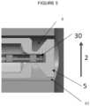
- the location of temperature measurement 30 of the sensing element 3might be placed as close as possible to the front face 5 of the thermowell body 1, which is flush with the inner diameter of a pipe 7 wherein fluid flows.
- a groove 4might be provided at the back of the front face 5.
- the groove 4extends radially inward of the thermowell body 1 and has been designed to minimize the cross-sectional area of the thermowell body 1 proximate the location of the temperature measurement 30 of the sensing element 3.
- the groove 4might be positioned such that the location of the temperature measurement 30 is inside a front-end disk 6 of the thermowell body 1. This geometry enables to minimize the heat transfer between the measurement location 30 and the rest of the sensor body 1.
- the front face 5might be kept large to provide as much heat transfer as possible to the location 30 of measurement.
- the edge 60 of the front face disk 6might be curved or truncated to minimize the contact area with the pipe. This minimizes the heat transfer between the thermowell disk and the pipe 7.
- openings 61might be made in the front-end disk 6, adjacent to the pipe wall 7 to allow the fluids to circulate in the cavity formed by the groove 4. Fluid might then enter the groove 4 on the downstream side of the disk 6 due to impingement on the thermowell body 1 and exits the groove 4 on the upstream side.
- the measurement location 30is now surrounded with the fluid 2 to measure. The fluid velocity might promote heat transfer through convection. With such configuration, the measurement location 30 might be about fully surrounded by the fluid 2.
- an opening 61a on the downstream side of the disk 6might have a larger cross-sectional area than an opening 61b on the upstream side of the disk 6 .
- This featureenables to generate a differential pressure between the openings 61a and 61b, which might further enhance the circulation and renewal of the fluids at the back of the temperature measurement location 30.
- the thermowell body 1may be machined from a metallic bar or forge. Some coating may be added for heat transfer purposes or erosion purposes.
- the groove 4 at the back of the front face 5, creating a thermal chokemay be of any geometric shape.
- a transition regionmay be shaped other than in a cone fashion, the openings may be of substantially the same size or shaped upstream and downstream as previously discussed. Along these lines, a variety of different shapes may be used for the openings 61.
- the disk 6may have edges 60 that are not truncated or be positioned other than as depicted, including having a front end that is not tangential to the flow and/or being positioned in a manner that is not completely flush with the pipe inner wall (whether slightly protruding or recessed).
- FIGs. 5-6herein are provided as additional representations of embodiments for a substantially non-intrusive temperature assembly.
- Figure 5is a schematic representation of a nonintrusive temperature assembly of the disclosure.
- the front face 5 of the thermowell body 1is substantially flush with an inner diameter of a pipe wherein fluid 2 flows.
- the groove 4 at the back of the front face 5creates a thermal choke.
- opening 61are lodged between the thermowell body 1 and the pipe wall 7 so the fluid can flow through the openings 61 in the groove 4 and towards the sensor location 30 of measurement of temperature.
- Figure 6shows an embodiment of the thermowell body in greater detail.
- the temperature sensor assembly of the disclosuremay be implemented on multiphase sensing tools or anywhere in permanent or temporary subsea or topside processes where one needs to know the process temperature accurately while avoiding protruding into the flow (e.g. whether due to space limitations, risk of erosion, pressure losses, debris in the flow, etc.). For example, Christmas trees, injection lines and manifolds may benefit, among others, from this type of non-intrusive design.
- the assembly of the disclosuremay also provide (more) accurate temperature measurements of the flowing process fluid, relative to other non-intrusive measuring devices. This will in return improve the accuracy of other measurements or prediction and therefore improve or reduce overall operating expenses.
Landscapes
- Physics & Mathematics (AREA)
- General Physics & Mathematics (AREA)
- Measuring Temperature Or Quantity Of Heat (AREA)
Description
- The present disclosure is related in general to monitoring of well conditions such as temperature of flowing well fluids. Monitoring temperature in this manner may be beneficial in maintaining and managing production from the well. For example, when producing hydrocarbon wells, the emergence of undesirable water production is often initially detected by changing temperature of flowing well fluids.
- Unfortunately, monitoring fluid temperature of well fluids may be more complicated than merely placing a sensor in a conduit carrying the fluid. For example, there is generally a desire to avoid placing a sensor intrusively in the fluid flow which might obstruct the flow or lead to undesired perturbation, such as induced vibrations or system fatigue. Additionally, in circumstances where the fluid is gaseous or multiphase, the detection itself may be challenging to attain in an accurate manner, particularly where the sensor is only indirectly in contact with the fluid flow.
- Efforts to address these issues have been made which involve placing the sensor at an embedded location of the pipe supporting the conduit for fluid flow. This may include the use of a thermowell housing for the sensor. Unfortunately, this leads to poor accuracy. That is, fluctuation of the temperature of the flowing fluid may not readily be picked up on by the sensor which is in closer association with the pipe which is not as responsive in fluctuating temperature. Further, for example but not limited to, in circumstances wherein the pipe is not insulated, the temperature gradient of the pipe is unlikely to match that of the flowing fluid within the pipe due to other influences such as the temperature of the environment outside of the pipe. Thus, even when the temperature is steady and not fluctuating, it is likely that the pipe temperature will not consistently match the temperature of the flowing fluid therein.
WO2017085511 A1 discloses a thermowell sensor assembly for monitoring temperature and vibration inside a conduit carrying a process fluid such as recovered or post-processed hydrocarbon in gas or liquid form, wherein the thermowell protrudes inside the conduit.US2018031397 A1 discloses a thermowell assembly for monitoring temperature of a process fluid flowing through a conduit, for example hydrocarbons or water, wherein the thermowell protrudes inside the conduit.US 5667306 A1 describes a digital water temperature reading device for a spa, swimming pool and whirlpool. A temperature probe is located inside an adaptor screwed in one of the waste openings of a filtration or pumping system. The adaptor serves as receptacle for the temperature probe and to replace the waste plug otherwise located in the opening. The adaptor includes a dome receiving a contact point of the temperature probe in its concave part and getting in touch with the bath water in its convex part. The dome is surrounded by a circulation channel facilitating the heat transfer between the water and the contact point.US 5022766 A1 describes a temperature sensing device including a housing for attachment to a wall of a building in an inconspicuous and decoratively functional housing designed to complement the interior decor of a room. The housing itself includes a head portion which protects the delicate sensor head from contact with a foreign object which could damage the sensor. Insulation is provided around the sensor cap to prevent the sensor from being influenced by the wall temperature. A seal is provided at the back of the sensor housing to prevent interior wall air from entering the sensor housing and providing a false reading of the ambient room air temperature.- The present disclosure provides various embodiments of assemblies and/or methods of utilizing a temperature apparatus of unique architecture. While the embodiments may be particularly beneficial for use in monitoring hydrocarbon gas production -due to the relatively low density and thermal conductivity- every business segment which requires subsea or topside temperature measurement of fluid flow via non-intrusive means may benefit from the embodiments described herein.
- Embodiments detailed herein may be beneficial to applications where the fluid properties being measured are highly sensitive to temperature such as those directed at measuring salinity, fluid conductivity, viscosity and permittivity. That is, the more accurate the fluid temperature measurement is, the more accurate these types of applications are given the reliance on temperature. More specifically, such applications yield maximum accuracy where the associated fluid temperature measurement is of an accuracy of about +/-0.5°C. However, at present, current non-intrusive solutions to measure temperature have an accuracy between +/-5°C and +/-40°C in the worst cases. Embodiments herein, however, may reach the target of +/-0.5°C under favorable conditions.
- The embodiments discussed herein are directed at a non-intrusive configuration that allows temperature measurements of flowing fluids with much higher accuracy and shorter time response than other known non-intrusive temperature measurement solutions. In embodiments, the geometry is such that it allows the temperature element inside a thermowell body to remain substantially flush with the inner diameter of the pipe carrying a flowing fluid. The thermowell body possesses a groove at the back of its flush face and openings at the front to allow the flowing fluids to circulate around the location of the temperature measurement. By doing so, the temperature sensing element is mostly surrounded by the fluids from which the temperature needs to be measured. The configuration of the disclosure can be used with any kind of temperature sensing technology (pt100, thermocouple, optical and others), is robust and cost effective.
- The present invention resides in a temperature sensor assembly for measuring temperature of a fluid in a conduit as defined in
claim 1. Preferred embodiments are defined in the dependent claims - For a detailed description of exemplary embodiments, reference will now be made to the accompanying drawings in which:
Figure 1 represents a nonintrusive temperature assembly according to embodiments of the disclosure;Figure 2 represents a nonintrusive temperature assembly according to further embodiments of the disclosure;Figure 3 represents a nonintrusive temperature assembly according to further embodiments of the disclosure;Figure 4 represents a nonintrusive temperature assembly according to further embodiments of the disclosure;Figures 5 to 6 represent further schematic embodiments of a nonintrusive temperature assembly according to the disclosure.- With specific reference to the illustration of
Fig. 1 , a non-intrusive temperature assembly according to embodiments of the disclosure is described to enable acquiring accurate and fast temperature measurement by maximizing the heat transfer from a fluid (gas or liquid, single or multiphase) flowing inside a pipe while minimizing the heat transfer to the remainder of thethermowell body 1. For example, in embodiments of the disclosure, athermowell body 1 hosts asensing element 3 that might be at least in part surrounded by thefluid 2 to reinforce accuracy while in the meantime having as little thermal mass as possible to enhance quick time response. To achieve this with a non-intrusive device, the assembly of the disclosure provides appropriate design as further described below. In embodiments, the location oftemperature measurement 30 of thesensing element 3 might be placed as close as possible to thefront face 5 of thethermowell body 1, which is flush with the inner diameter of apipe 7 wherein fluid flows. Additionally, agroove 4 might be provided at the back of thefront face 5. Thegroove 4 extends radially inward of thethermowell body 1 and has been designed to minimize the cross-sectional area of thethermowell body 1 proximate the location of thetemperature measurement 30 of thesensing element 3. Thegroove 4 might be positioned such that the location of thetemperature measurement 30 is inside a front-end disk 6 of thethermowell body 1. This geometry enables to minimize the heat transfer between themeasurement location 30 and the rest of thesensor body 1. - With specific reference to
Fig. 2 , in embodiments of the assembly of the disclosure, thefront face 5 might be kept large to provide as much heat transfer as possible to thelocation 30 of measurement. However, theedge 60 of thefront face disk 6 might be curved or truncated to minimize the contact area with the pipe. This minimizes the heat transfer between the thermowell disk and thepipe 7. - With specific reference to
Fig. 3 , in one embodiment of the assembly of the disclosure,openings 61 might be made in the front-end disk 6, adjacent to thepipe wall 7 to allow the fluids to circulate in the cavity formed by thegroove 4. Fluid might then enter thegroove 4 on the downstream side of thedisk 6 due to impingement on thethermowell body 1 and exits thegroove 4 on the upstream side. Themeasurement location 30 is now surrounded with thefluid 2 to measure. The fluid velocity might promote heat transfer through convection. With such configuration, themeasurement location 30 might be about fully surrounded by thefluid 2. - With specific reference to
Fig. 4 , in an embodiment of the system of the disclosure, an opening 61a on the downstream side of thedisk 6 might have a larger cross-sectional area than an opening 61b on the upstream side of thedisk 6 . This feature enables to generate a differential pressure between theopenings 61a and 61b, which might further enhance the circulation and renewal of the fluids at the back of thetemperature measurement location 30. - In embodiments, the
thermowell body 1 may be machined from a metallic bar or forge. Some coating may be added for heat transfer purposes or erosion purposes. In addition to the embodiments depicted herein, it should be noted that thegroove 4 at the back of thefront face 5, creating a thermal choke, may be of any geometric shape. For example, a transition region may be shaped other than in a cone fashion, the openings may be of substantially the same size or shaped upstream and downstream as previously discussed. Along these lines, a variety of different shapes may be used for theopenings 61. Further, thedisk 6 may haveedges 60 that are not truncated or be positioned other than as depicted, including having a front end that is not tangential to the flow and/or being positioned in a manner that is not completely flush with the pipe inner wall (whether slightly protruding or recessed). Figs. 5-6 herein are provided as additional representations of embodiments for a substantially non-intrusive temperature assembly.Figure 5 is a schematic representation of a nonintrusive temperature assembly of the disclosure. Thefront face 5 of thethermowell body 1 is substantially flush with an inner diameter of a pipe wherein fluid 2 flows. Thegroove 4 at the back of thefront face 5 creates a thermal choke. In the represented embodiment, opening 61 are lodged between thethermowell body 1 and thepipe wall 7 so the fluid can flow through theopenings 61 in thegroove 4 and towards thesensor location 30 of measurement of temperature.Figure 6 shows an embodiment of the thermowell body in greater detail.- The temperature sensor assembly of the disclosure may be implemented on multiphase sensing tools or anywhere in permanent or temporary subsea or topside processes where one needs to know the process temperature accurately while avoiding protruding into the flow (e.g. whether due to space limitations, risk of erosion, pressure losses, debris in the flow, etc.). For example, Christmas trees, injection lines and manifolds may benefit, among others, from this type of non-intrusive design.
- The assembly of the disclosure may also provide (more) accurate temperature measurements of the flowing process fluid, relative to other non-intrusive measuring devices. This will in return improve the accuracy of other measurements or prediction and therefore improve or reduce overall operating expenses.
Claims (5)
- A temperature sensor assembly for measuring temperature of a hydrocarbon fluid flowing in a conduit (7), the assembly comprising:a temperature sensor (3); anda thermowell body (1) housing the temperature sensor and configured to be embedded in a wall defining the conduit (7),characterized by the thermowell body (1) comprising a front-end disk (6) having a front face (5) for interfacing with the fluid, the front face (5) being configured to be flush with the wall defining the conduit (7) and a groove (4) disposed behind the front-end disk (6), the groove (4) extending radially inward of the front face (5) and defining a cavity in which the fluid can circulate, wherein the groove (4) is configured to minimize the cross-sectional area of the thermowell body (1) proximate the location (30) of the temperature sensor.
- The assembly of claim 1 wherein the front face (5) includes at least two openings (61) to circulate fluid from the conduit (7) toward the cavity defined by the groove (4).
- The assembly of claim 2 wherein a first opening (61b) of the at least two openings is upstream of a second opening (61a) of the at least two openings.
- The assembly of claim 3 wherein the second opening (61b) is larger than the first opening (61a) to promote a differential pressure for the circulation of the fluid.
- The assembly of claim 1 wherein the front-end disk (6) comprises at least one side configured to be in physical contact with the wall, the side of the front-end disk (6) being rounded to minimize heat transfer therebetween.
Applications Claiming Priority (2)
| Application Number | Priority Date | Filing Date | Title |
|---|---|---|---|
| US201962845622P | 2019-05-09 | 2019-05-09 | |
| PCT/EP2020/062892WO2020225424A1 (en) | 2019-05-09 | 2020-05-08 | Temperature sensor assembly |
Publications (2)
| Publication Number | Publication Date |
|---|---|
| EP3966538A1 EP3966538A1 (en) | 2022-03-16 |
| EP3966538B1true EP3966538B1 (en) | 2023-05-03 |
Family
ID=70775325
Family Applications (1)
| Application Number | Title | Priority Date | Filing Date |
|---|---|---|---|
| EP20723780.1AActiveEP3966538B1 (en) | 2019-05-09 | 2020-05-08 | Temperature sensor assembly |
Country Status (3)
| Country | Link |
|---|---|
| US (1) | US11808636B2 (en) |
| EP (1) | EP3966538B1 (en) |
| WO (1) | WO2020225424A1 (en) |
Family Cites Families (9)
| Publication number | Priority date | Publication date | Assignee | Title |
|---|---|---|---|---|
| JPS585938Y2 (en)* | 1977-04-19 | 1983-02-01 | 三井造船株式会社 | Mounting structure of sheath thermocouple |
| JPS53143688A (en) | 1977-05-23 | 1978-12-14 | Mitsui Polychemicals Ltd | Novel thermoplastic polymer producing process thereof and soillresistant filmmforming agent |
| US5022766A (en)* | 1990-01-19 | 1991-06-11 | Phipps Jack M | Temperature sensing device |
| JPH06160124A (en)* | 1992-11-20 | 1994-06-07 | Mitsubishi Heavy Ind Ltd | Sensor fitting metal |
| CA2148017A1 (en)* | 1995-04-27 | 1996-10-28 | Richard Montreuil | Device for digital reading of spa, pool and whirlpool water temperature |
| US5857775A (en)* | 1995-09-05 | 1999-01-12 | Tyco Group S.A.R.L. | Thermometer probe having a watertight seal |
| US6354734B1 (en)* | 1999-11-04 | 2002-03-12 | Kvaerner Oilfield Products, Inc. | Apparatus for accurate temperature and pressure measurement |
| US7751677B2 (en)* | 2005-06-30 | 2010-07-06 | Weatherford/Lamb, Inc. | Optical fiber feedthrough using axial seals for bi-directional sealing |
| EP3049618B1 (en)* | 2013-09-27 | 2018-05-09 | National Oilwell Varco, L.P. | Downhole temperature sensing of the fluid flow in and around a drill string tool |
- 2020
- 2020-05-08EPEP20723780.1Apatent/EP3966538B1/enactiveActive
- 2020-05-08WOPCT/EP2020/062892patent/WO2020225424A1/ennot_activeCeased
- 2020-05-08USUS17/609,595patent/US11808636B2/enactiveActive
Also Published As
| Publication number | Publication date |
|---|---|
| US11808636B2 (en) | 2023-11-07 |
| US20220228927A1 (en) | 2022-07-21 |
| EP3966538A1 (en) | 2022-03-16 |
| WO2020225424A1 (en) | 2020-11-12 |
Similar Documents
| Publication | Publication Date | Title |
|---|---|---|
| EP2559987B1 (en) | Combination pressure/temperature in a compact sensor assembly | |
| EP2635770B1 (en) | Distributed fluid velocity sensor and associated method | |
| US20110185815A1 (en) | Detection of deposits in flowlines | |
| US8061219B2 (en) | Flow restriction insert for differential pressure measurement | |
| US6354734B1 (en) | Apparatus for accurate temperature and pressure measurement | |
| US9068869B2 (en) | Magnetic flowmeter with bonded PTFE electrodes | |
| EP3201574B1 (en) | Magnetic flowmeter with vapor permeation sensor | |
| US11002628B2 (en) | Thermowell with primary seal verification | |
| BRPI1103833A2 (en) | Device for measuring the characteristics of a flow in a pipe | |
| US11473951B2 (en) | Flow direction sensor | |
| CN103727304A (en) | Cavitation evaluating device | |
| EP3966538B1 (en) | Temperature sensor assembly | |
| KR101115575B1 (en) | Device of measuring the temperature and pressure probe | |
| SA122431229B1 (en) | Determining Thermal Conditions in A Pipeline | |
| CN106017775A (en) | Pipe with testing function | |
| JP6672834B2 (en) | Water level detector | |
| CN104024626B (en) | Cylinder head | |
| EP2522997B1 (en) | Monitoring hydrocarbon fluid flow | |
| EP3553482A1 (en) | Thermowell with reduced sensitivity to vortex induced vibrations | |
| EP3203203B1 (en) | Sensor device | |
| JP2015108442A (en) | Trap | |
| SA522431687B1 (en) | A method for measuring the level of a fluid in a pressure vessel | |
| US10018513B1 (en) | Thermowell extension | |
| JP4411917B2 (en) | Vortex flow meter | |
| CN103674340B (en) | A kind of mould resistance sensor |
Legal Events
| Date | Code | Title | Description |
|---|---|---|---|
| STAA | Information on the status of an ep patent application or granted ep patent | Free format text:STATUS: UNKNOWN | |
| STAA | Information on the status of an ep patent application or granted ep patent | Free format text:STATUS: THE INTERNATIONAL PUBLICATION HAS BEEN MADE | |
| PUAI | Public reference made under article 153(3) epc to a published international application that has entered the european phase | Free format text:ORIGINAL CODE: 0009012 | |
| STAA | Information on the status of an ep patent application or granted ep patent | Free format text:STATUS: REQUEST FOR EXAMINATION WAS MADE | |
| 17P | Request for examination filed | Effective date:20211109 | |
| AK | Designated contracting states | Kind code of ref document:A1 Designated state(s):AL AT BE BG CH CY CZ DE DK EE ES FI FR GB GR HR HU IE IS IT LI LT LU LV MC MK MT NL NO PL PT RO RS SE SI SK SM TR | |
| DAV | Request for validation of the european patent (deleted) | ||
| DAX | Request for extension of the european patent (deleted) | ||
| REG | Reference to a national code | Ref country code:DE Ref legal event code:R079 Ref document number:602020010451 Country of ref document:DE Free format text:PREVIOUS MAIN CLASS: G01K0001140000 Ipc:G01K0001143000 | |
| RIC1 | Information provided on ipc code assigned before grant | Ipc:G01K 1/16 20060101ALI20220912BHEP Ipc:G01K 13/02 20210101ALI20220912BHEP Ipc:G01K 1/143 20210101AFI20220912BHEP | |
| GRAP | Despatch of communication of intention to grant a patent | Free format text:ORIGINAL CODE: EPIDOSNIGR1 | |
| STAA | Information on the status of an ep patent application or granted ep patent | Free format text:STATUS: GRANT OF PATENT IS INTENDED | |
| INTG | Intention to grant announced | Effective date:20221111 | |
| GRAS | Grant fee paid | Free format text:ORIGINAL CODE: EPIDOSNIGR3 | |
| GRAA | (expected) grant | Free format text:ORIGINAL CODE: 0009210 | |
| STAA | Information on the status of an ep patent application or granted ep patent | Free format text:STATUS: THE PATENT HAS BEEN GRANTED | |
| AK | Designated contracting states | Kind code of ref document:B1 Designated state(s):AL AT BE BG CH CY CZ DE DK EE ES FI FR GB GR HR HU IE IS IT LI LT LU LV MC MK MT NL NO PL PT RO RS SE SI SK SM TR | |
| REG | Reference to a national code | Ref country code:GB Ref legal event code:FG4D | |
| REG | Reference to a national code | Ref country code:DE Ref legal event code:R096 Ref document number:602020010451 Country of ref document:DE | |
| REG | Reference to a national code | Ref country code:AT Ref legal event code:REF Ref document number:1564990 Country of ref document:AT Kind code of ref document:T Effective date:20230515 Ref country code:CH Ref legal event code:EP | |
| REG | Reference to a national code | Ref country code:IE Ref legal event code:FG4D | |
| REG | Reference to a national code | Ref country code:LT Ref legal event code:MG9D | |
| REG | Reference to a national code | Ref country code:NL Ref legal event code:MP Effective date:20230503 | |
| REG | Reference to a national code | Ref country code:NO Ref legal event code:T2 Effective date:20230503 | |
| REG | Reference to a national code | Ref country code:AT Ref legal event code:MK05 Ref document number:1564990 Country of ref document:AT Kind code of ref document:T Effective date:20230503 | |
| PG25 | Lapsed in a contracting state [announced via postgrant information from national office to epo] | Ref country code:SE Free format text:LAPSE BECAUSE OF FAILURE TO SUBMIT A TRANSLATION OF THE DESCRIPTION OR TO PAY THE FEE WITHIN THE PRESCRIBED TIME-LIMIT Effective date:20230503 Ref country code:PT Free format text:LAPSE BECAUSE OF FAILURE TO SUBMIT A TRANSLATION OF THE DESCRIPTION OR TO PAY THE FEE WITHIN THE PRESCRIBED TIME-LIMIT Effective date:20230904 Ref country code:NL Free format text:LAPSE BECAUSE OF FAILURE TO SUBMIT A TRANSLATION OF THE DESCRIPTION OR TO PAY THE FEE WITHIN THE PRESCRIBED TIME-LIMIT Effective date:20230503 Ref country code:ES Free format text:LAPSE BECAUSE OF FAILURE TO SUBMIT A TRANSLATION OF THE DESCRIPTION OR TO PAY THE FEE WITHIN THE PRESCRIBED TIME-LIMIT Effective date:20230503 Ref country code:AT Free format text:LAPSE BECAUSE OF FAILURE TO SUBMIT A TRANSLATION OF THE DESCRIPTION OR TO PAY THE FEE WITHIN THE PRESCRIBED TIME-LIMIT Effective date:20230503 | |
| REG | Reference to a national code | Ref country code:NO Ref legal event code:CHAD Owner name:SCHLUMBERGER TECHNOLOGY B.V., NL | |
| REG | Reference to a national code | Ref country code:GB Ref legal event code:732E Free format text:REGISTERED BETWEEN 20231019 AND 20231025 | |
| PG25 | Lapsed in a contracting state [announced via postgrant information from national office to epo] | Ref country code:RS Free format text:LAPSE BECAUSE OF FAILURE TO SUBMIT A TRANSLATION OF THE DESCRIPTION OR TO PAY THE FEE WITHIN THE PRESCRIBED TIME-LIMIT Effective date:20230503 Ref country code:PL Free format text:LAPSE BECAUSE OF FAILURE TO SUBMIT A TRANSLATION OF THE DESCRIPTION OR TO PAY THE FEE WITHIN THE PRESCRIBED TIME-LIMIT Effective date:20230503 Ref country code:LV Free format text:LAPSE BECAUSE OF FAILURE TO SUBMIT A TRANSLATION OF THE DESCRIPTION OR TO PAY THE FEE WITHIN THE PRESCRIBED TIME-LIMIT Effective date:20230503 Ref country code:LT Free format text:LAPSE BECAUSE OF FAILURE TO SUBMIT A TRANSLATION OF THE DESCRIPTION OR TO PAY THE FEE WITHIN THE PRESCRIBED TIME-LIMIT Effective date:20230503 Ref country code:IS Free format text:LAPSE BECAUSE OF FAILURE TO SUBMIT A TRANSLATION OF THE DESCRIPTION OR TO PAY THE FEE WITHIN THE PRESCRIBED TIME-LIMIT Effective date:20230903 Ref country code:HR Free format text:LAPSE BECAUSE OF FAILURE TO SUBMIT A TRANSLATION OF THE DESCRIPTION OR TO PAY THE FEE WITHIN THE PRESCRIBED TIME-LIMIT Effective date:20230503 Ref country code:GR Free format text:LAPSE BECAUSE OF FAILURE TO SUBMIT A TRANSLATION OF THE DESCRIPTION OR TO PAY THE FEE WITHIN THE PRESCRIBED TIME-LIMIT Effective date:20230804 | |
| REG | Reference to a national code | Ref country code:DE Ref legal event code:R119 Ref document number:602020010451 Country of ref document:DE | |
| PG25 | Lapsed in a contracting state [announced via postgrant information from national office to epo] | Ref country code:FI Free format text:LAPSE BECAUSE OF FAILURE TO SUBMIT A TRANSLATION OF THE DESCRIPTION OR TO PAY THE FEE WITHIN THE PRESCRIBED TIME-LIMIT Effective date:20230503 | |
| REG | Reference to a national code | Ref country code:CH Ref legal event code:PL | |
| PG25 | Lapsed in a contracting state [announced via postgrant information from national office to epo] | Ref country code:SK Free format text:LAPSE BECAUSE OF FAILURE TO SUBMIT A TRANSLATION OF THE DESCRIPTION OR TO PAY THE FEE WITHIN THE PRESCRIBED TIME-LIMIT Effective date:20230503 | |
| P01 | Opt-out of the competence of the unified patent court (upc) registered | Effective date:20231212 | |
| REG | Reference to a national code | Ref country code:BE Ref legal event code:MM Effective date:20230531 | |
| PG25 | Lapsed in a contracting state [announced via postgrant information from national office to epo] | Ref country code:SM Free format text:LAPSE BECAUSE OF FAILURE TO SUBMIT A TRANSLATION OF THE DESCRIPTION OR TO PAY THE FEE WITHIN THE PRESCRIBED TIME-LIMIT Effective date:20230503 Ref country code:SK Free format text:LAPSE BECAUSE OF FAILURE TO SUBMIT A TRANSLATION OF THE DESCRIPTION OR TO PAY THE FEE WITHIN THE PRESCRIBED TIME-LIMIT Effective date:20230503 Ref country code:RO Free format text:LAPSE BECAUSE OF FAILURE TO SUBMIT A TRANSLATION OF THE DESCRIPTION OR TO PAY THE FEE WITHIN THE PRESCRIBED TIME-LIMIT Effective date:20230503 Ref country code:LU Free format text:LAPSE BECAUSE OF NON-PAYMENT OF DUE FEES Effective date:20230508 Ref country code:LI Free format text:LAPSE BECAUSE OF NON-PAYMENT OF DUE FEES Effective date:20230531 Ref country code:EE Free format text:LAPSE BECAUSE OF FAILURE TO SUBMIT A TRANSLATION OF THE DESCRIPTION OR TO PAY THE FEE WITHIN THE PRESCRIBED TIME-LIMIT Effective date:20230503 Ref country code:DK Free format text:LAPSE BECAUSE OF FAILURE TO SUBMIT A TRANSLATION OF THE DESCRIPTION OR TO PAY THE FEE WITHIN THE PRESCRIBED TIME-LIMIT Effective date:20230503 Ref country code:CZ Free format text:LAPSE BECAUSE OF FAILURE TO SUBMIT A TRANSLATION OF THE DESCRIPTION OR TO PAY THE FEE WITHIN THE PRESCRIBED TIME-LIMIT Effective date:20230503 Ref country code:CH Free format text:LAPSE BECAUSE OF NON-PAYMENT OF DUE FEES Effective date:20230531 | |
| PG25 | Lapsed in a contracting state [announced via postgrant information from national office to epo] | Ref country code:MC Free format text:LAPSE BECAUSE OF FAILURE TO SUBMIT A TRANSLATION OF THE DESCRIPTION OR TO PAY THE FEE WITHIN THE PRESCRIBED TIME-LIMIT Effective date:20230503 | |
| REG | Reference to a national code | Ref country code:IE Ref legal event code:MM4A | |
| PG25 | Lapsed in a contracting state [announced via postgrant information from national office to epo] | Ref country code:MC Free format text:LAPSE BECAUSE OF FAILURE TO SUBMIT A TRANSLATION OF THE DESCRIPTION OR TO PAY THE FEE WITHIN THE PRESCRIBED TIME-LIMIT Effective date:20230503 | |
| PLBE | No opposition filed within time limit | Free format text:ORIGINAL CODE: 0009261 | |
| STAA | Information on the status of an ep patent application or granted ep patent | Free format text:STATUS: NO OPPOSITION FILED WITHIN TIME LIMIT | |
| 26N | No opposition filed | Effective date:20240206 | |
| PG25 | Lapsed in a contracting state [announced via postgrant information from national office to epo] | Ref country code:IE Free format text:LAPSE BECAUSE OF NON-PAYMENT OF DUE FEES Effective date:20230508 | |
| PG25 | Lapsed in a contracting state [announced via postgrant information from national office to epo] | Ref country code:DE Free format text:LAPSE BECAUSE OF NON-PAYMENT OF DUE FEES Effective date:20231201 Ref country code:IE Free format text:LAPSE BECAUSE OF NON-PAYMENT OF DUE FEES Effective date:20230508 | |
| PG25 | Lapsed in a contracting state [announced via postgrant information from national office to epo] | Ref country code:SI Free format text:LAPSE BECAUSE OF FAILURE TO SUBMIT A TRANSLATION OF THE DESCRIPTION OR TO PAY THE FEE WITHIN THE PRESCRIBED TIME-LIMIT Effective date:20230503 | |
| PG25 | Lapsed in a contracting state [announced via postgrant information from national office to epo] | Ref country code:SI Free format text:LAPSE BECAUSE OF FAILURE TO SUBMIT A TRANSLATION OF THE DESCRIPTION OR TO PAY THE FEE WITHIN THE PRESCRIBED TIME-LIMIT Effective date:20230503 Ref country code:IT Free format text:LAPSE BECAUSE OF FAILURE TO SUBMIT A TRANSLATION OF THE DESCRIPTION OR TO PAY THE FEE WITHIN THE PRESCRIBED TIME-LIMIT Effective date:20230503 Ref country code:FR Free format text:LAPSE BECAUSE OF NON-PAYMENT OF DUE FEES Effective date:20230703 Ref country code:BE Free format text:LAPSE BECAUSE OF NON-PAYMENT OF DUE FEES Effective date:20230531 | |
| PG25 | Lapsed in a contracting state [announced via postgrant information from national office to epo] | Ref country code:BG Free format text:LAPSE BECAUSE OF FAILURE TO SUBMIT A TRANSLATION OF THE DESCRIPTION OR TO PAY THE FEE WITHIN THE PRESCRIBED TIME-LIMIT Effective date:20230503 | |
| PG25 | Lapsed in a contracting state [announced via postgrant information from national office to epo] | Ref country code:BG Free format text:LAPSE BECAUSE OF FAILURE TO SUBMIT A TRANSLATION OF THE DESCRIPTION OR TO PAY THE FEE WITHIN THE PRESCRIBED TIME-LIMIT Effective date:20230503 | |
| PGFP | Annual fee paid to national office [announced via postgrant information from national office to epo] | Ref country code:GB Payment date:20250320 Year of fee payment:6 | |
| PGFP | Annual fee paid to national office [announced via postgrant information from national office to epo] | Ref country code:NO Payment date:20250509 Year of fee payment:6 | |
| PG25 | Lapsed in a contracting state [announced via postgrant information from national office to epo] | Ref country code:CY Free format text:LAPSE BECAUSE OF FAILURE TO SUBMIT A TRANSLATION OF THE DESCRIPTION OR TO PAY THE FEE WITHIN THE PRESCRIBED TIME-LIMIT; INVALID AB INITIO Effective date:20200508 | |
| PG25 | Lapsed in a contracting state [announced via postgrant information from national office to epo] | Ref country code:HU Free format text:LAPSE BECAUSE OF FAILURE TO SUBMIT A TRANSLATION OF THE DESCRIPTION OR TO PAY THE FEE WITHIN THE PRESCRIBED TIME-LIMIT; INVALID AB INITIO Effective date:20200508 |