EP3964146B1 - Medical devices having releasable coupling - Google Patents
Medical devices having releasable couplingDownload PDFInfo
- Publication number
- EP3964146B1 EP3964146B1EP21196279.0AEP21196279AEP3964146B1EP 3964146 B1EP3964146 B1EP 3964146B1EP 21196279 AEP21196279 AEP 21196279AEP 3964146 B1EP3964146 B1EP 3964146B1
- Authority
- EP
- European Patent Office
- Prior art keywords
- handle
- catheter
- control member
- attachment
- attachment member
- Prior art date
- Legal status (The legal status is an assumption and is not a legal conclusion. Google has not performed a legal analysis and makes no representation as to the accuracy of the status listed.)
- Active
Links
Images


Classifications
- A—HUMAN NECESSITIES
- A61—MEDICAL OR VETERINARY SCIENCE; HYGIENE
- A61M—DEVICES FOR INTRODUCING MEDIA INTO, OR ONTO, THE BODY; DEVICES FOR TRANSDUCING BODY MEDIA OR FOR TAKING MEDIA FROM THE BODY; DEVICES FOR PRODUCING OR ENDING SLEEP OR STUPOR
- A61M25/00—Catheters; Hollow probes
- A61M25/0043—Catheters; Hollow probes characterised by structural features
- A—HUMAN NECESSITIES
- A61—MEDICAL OR VETERINARY SCIENCE; HYGIENE
- A61B—DIAGNOSIS; SURGERY; IDENTIFICATION
- A61B17/00—Surgical instruments, devices or methods
- A61B17/28—Surgical forceps
- A61B17/29—Forceps for use in minimally invasive surgery
- A61B17/2909—Handles
- A—HUMAN NECESSITIES
- A61—MEDICAL OR VETERINARY SCIENCE; HYGIENE
- A61M—DEVICES FOR INTRODUCING MEDIA INTO, OR ONTO, THE BODY; DEVICES FOR TRANSDUCING BODY MEDIA OR FOR TAKING MEDIA FROM THE BODY; DEVICES FOR PRODUCING OR ENDING SLEEP OR STUPOR
- A61M25/00—Catheters; Hollow probes
- A61M25/0009—Making of catheters or other medical or surgical tubes
- A—HUMAN NECESSITIES
- A61—MEDICAL OR VETERINARY SCIENCE; HYGIENE
- A61M—DEVICES FOR INTRODUCING MEDIA INTO, OR ONTO, THE BODY; DEVICES FOR TRANSDUCING BODY MEDIA OR FOR TAKING MEDIA FROM THE BODY; DEVICES FOR PRODUCING OR ENDING SLEEP OR STUPOR
- A61M25/00—Catheters; Hollow probes
- A61M25/01—Introducing, guiding, advancing, emplacing or holding catheters
- A61M25/0105—Steering means as part of the catheter or advancing means; Markers for positioning
- A61M25/0113—Mechanical advancing means, e.g. catheter dispensers
- A—HUMAN NECESSITIES
- A61—MEDICAL OR VETERINARY SCIENCE; HYGIENE
- A61M—DEVICES FOR INTRODUCING MEDIA INTO, OR ONTO, THE BODY; DEVICES FOR TRANSDUCING BODY MEDIA OR FOR TAKING MEDIA FROM THE BODY; DEVICES FOR PRODUCING OR ENDING SLEEP OR STUPOR
- A61M25/00—Catheters; Hollow probes
- A61M25/01—Introducing, guiding, advancing, emplacing or holding catheters
- A61M25/0105—Steering means as part of the catheter or advancing means; Markers for positioning
- A61M25/0133—Tip steering devices
- A61M25/0136—Handles therefor
- A—HUMAN NECESSITIES
- A61—MEDICAL OR VETERINARY SCIENCE; HYGIENE
- A61M—DEVICES FOR INTRODUCING MEDIA INTO, OR ONTO, THE BODY; DEVICES FOR TRANSDUCING BODY MEDIA OR FOR TAKING MEDIA FROM THE BODY; DEVICES FOR PRODUCING OR ENDING SLEEP OR STUPOR
- A61M25/00—Catheters; Hollow probes
- A61M25/01—Introducing, guiding, advancing, emplacing or holding catheters
- A61M25/0105—Steering means as part of the catheter or advancing means; Markers for positioning
- A61M25/0133—Tip steering devices
- A61M25/0147—Tip steering devices with movable mechanical means, e.g. pull wires
- A—HUMAN NECESSITIES
- A61—MEDICAL OR VETERINARY SCIENCE; HYGIENE
- A61B—DIAGNOSIS; SURGERY; IDENTIFICATION
- A61B17/00—Surgical instruments, devices or methods
- A61B17/00234—Surgical instruments, devices or methods for minimally invasive surgery
- A61B2017/00292—Surgical instruments, devices or methods for minimally invasive surgery mounted on or guided by flexible, e.g. catheter-like, means
- A61B2017/003—Steerable
- A61B2017/00318—Steering mechanisms
- A61B2017/00323—Cables or rods
- A—HUMAN NECESSITIES
- A61—MEDICAL OR VETERINARY SCIENCE; HYGIENE
- A61B—DIAGNOSIS; SURGERY; IDENTIFICATION
- A61B17/00—Surgical instruments, devices or methods
- A61B2017/0046—Surgical instruments, devices or methods with a releasable handle; with handle and operating part separable
- A—HUMAN NECESSITIES
- A61—MEDICAL OR VETERINARY SCIENCE; HYGIENE
- A61B—DIAGNOSIS; SURGERY; IDENTIFICATION
- A61B17/00—Surgical instruments, devices or methods
- A61B2017/00477—Coupling
- A—HUMAN NECESSITIES
- A61—MEDICAL OR VETERINARY SCIENCE; HYGIENE
- A61B—DIAGNOSIS; SURGERY; IDENTIFICATION
- A61B17/00—Surgical instruments, devices or methods
- A61B17/28—Surgical forceps
- A61B17/29—Forceps for use in minimally invasive surgery
- A61B2017/2901—Details of shaft
- A61B2017/2905—Details of shaft flexible
- A—HUMAN NECESSITIES
- A61—MEDICAL OR VETERINARY SCIENCE; HYGIENE
- A61B—DIAGNOSIS; SURGERY; IDENTIFICATION
- A61B17/00—Surgical instruments, devices or methods
- A61B17/28—Surgical forceps
- A61B17/29—Forceps for use in minimally invasive surgery
- A61B17/2909—Handles
- A61B2017/291—Handles the position of the handle being adjustable with respect to the shaft
- A—HUMAN NECESSITIES
- A61—MEDICAL OR VETERINARY SCIENCE; HYGIENE
- A61B—DIAGNOSIS; SURGERY; IDENTIFICATION
- A61B17/00—Surgical instruments, devices or methods
- A61B17/28—Surgical forceps
- A61B17/29—Forceps for use in minimally invasive surgery
- A61B17/2909—Handles
- A61B2017/2912—Handles transmission of forces to actuating rod or piston
- A61B2017/2919—Handles transmission of forces to actuating rod or piston details of linkages or pivot points
- A61B2017/292—Handles transmission of forces to actuating rod or piston details of linkages or pivot points connection of actuating rod to handle, e.g. ball end in recess
- A—HUMAN NECESSITIES
- A61—MEDICAL OR VETERINARY SCIENCE; HYGIENE
- A61B—DIAGNOSIS; SURGERY; IDENTIFICATION
- A61B17/00—Surgical instruments, devices or methods
- A61B17/28—Surgical forceps
- A61B17/29—Forceps for use in minimally invasive surgery
- A61B2017/2926—Details of heads or jaws
- A61B2017/2927—Details of heads or jaws the angular position of the head being adjustable with respect to the shaft
- A61B2017/2929—Details of heads or jaws the angular position of the head being adjustable with respect to the shaft with a head rotatable about the longitudinal axis of the shaft
- A—HUMAN NECESSITIES
- A61—MEDICAL OR VETERINARY SCIENCE; HYGIENE
- A61B—DIAGNOSIS; SURGERY; IDENTIFICATION
- A61B17/00—Surgical instruments, devices or methods
- A61B17/28—Surgical forceps
- A61B17/29—Forceps for use in minimally invasive surgery
- A61B2017/2926—Details of heads or jaws
- A61B2017/2932—Transmission of forces to jaw members
- A61B2017/2938—Independently actuatable jaw members, e.g. two actuating rods
- Y—GENERAL TAGGING OF NEW TECHNOLOGICAL DEVELOPMENTS; GENERAL TAGGING OF CROSS-SECTIONAL TECHNOLOGIES SPANNING OVER SEVERAL SECTIONS OF THE IPC; TECHNICAL SUBJECTS COVERED BY FORMER USPC CROSS-REFERENCE ART COLLECTIONS [XRACs] AND DIGESTS
- Y10—TECHNICAL SUBJECTS COVERED BY FORMER USPC
- Y10T—TECHNICAL SUBJECTS COVERED BY FORMER US CLASSIFICATION
- Y10T29/00—Metal working
- Y10T29/49—Method of mechanical manufacture
- Y10T29/49826—Assembling or joining
Definitions
- Embodiments of the present inventionrelate to medical devices.
- embodiments of the present inventioninclude medical devices having releasable coupling.
- Minimally invasive surgical toolssuch as endoscopic and laparoscopic devices, can provide access to surgical sites while minimizing patient trauma. Although the growing capabilities of such therapeutic devices allow physicians to perform an increasing variety of surgeries, further refinements are needed to reduce costs associated with such procedures.
- Some minimally invasive systemsinclude surgical devices that may be sterilized for reuse. Such devices are usually expensive to manufacture and must be designed to withstand multiple sterilization procedures. Similar disposable devices often have limited performance due to the use of cheaper materials and low-cost manufacturing techniques. Endoscopic and laparoscopic devices according to the prior art are described in US 2009/171147 A1 , WO 2010/101401 A2 , US 5860953 A , US 2008/287862 A1 and US 6059179 A .
- a medical devicethat can include some reusable and some disposable components.
- a medical devicecould include a reusable handle and a disposable catheter.
- the reusable handlecould be adapted for use with different types of catheters having different end-effectors.
- a medical deviceas recited in the independent claim.
- the dependent claimsdefine embodiments of the invention.
- a medical devicehaving a longitudinal axis, and including a handle and a catheter.
- the handleincludes a body having a proximal end and a distal end, an actuator moveably coupled to the body, and a handle control member coupled to the actuator, wherein the actuator is configured to move relative to the body to move the handle control member.
- the catheterincludes a shaft having a proximal end and a distal end, wherein the proximal end of the shaft and the distal end of the body are configured for releasable coupling.
- the catheteralso includes a steering section located along the shaft and a catheter control member coupled to the steering section, wherein the catheter control member is configured to move relative to the shaft to move the steering section relative to the longitudinal axis.
- the medical devicealso includes a securing member configured to move relative to at least one of the handle and the catheter to releasably couple the handle control member to the catheter control member.
- the handleconfigured to releasably couple to a catheter.
- the handlecan include a body configured to releasably couple to the catheter, an actuator moveably coupled to the body and configured to engage a user's hand, and a plurality of handle control members coupled to the actuator, wherein the actuator can be configured to move relative to the body to move at least one of the plurality of handle control members.
- the handlecan also include a securing member configured to move relative to the handle to releasably couple the plurality of handle control members to a plurality of catheter control members.
- the catheterconfigured to releasably couple to a handle.
- the cathetercan include a shaft configured to releasably couple to the handle, a steering section located along the shaft, and a plurality of catheter control members coupled to the steering section, wherein each of the plurality of catheter control members can include a first attachment member and can be configured to move relative to the shaft to move the steering section.
- the cathetercan also include a lumen configured to at least partially maintain coupling between the first attachment member and a corresponding attachment member located on a handle control member.
- the methodcan include moving a handle having a handle control member relative to a catheter having a catheter control member in untensioned state, to engage the handle control member with the catheter control member.
- the methodcan also include moving a securing member from a first position to a second position to tension the catheter control member and couple the handle control member to the catheter control member.
- FIG. 1depicts a device 10, according to an exemplary embodiment.
- Device 10is shown in a detached configuration, whereby a handle 50 is shown separated from a catheter 70.
- handle 50 and catheter 70are configured for releasable coupling.
- handle 50can be attached to catheter 70 to allow handle 50 to control a movement, actuation, and/or operation of catheter 70.
- Handle 50can also be detached from catheter 70 so that other catheters 70 may be attached to handle 50.
- handle 50could be reusable and catheter 70 could be disposable. Multiple catheters 70, having different end-effectors, could be used interchangeably with a single handle 50. Various different catheters 70 could be provided together in kit form, wherein each catheter 70 has a different end-effector.
- Device 10can include a medical device configured for use with a surgical method, including a therapeutic or diagnostic procedure.
- device 10can be configured for use with an endoscope, a guide tube, an access catheter, or other type of device configured to access a patient's body.
- Device 10may be used for procedures within or adjacent to various body organs, such as, an esophagus, a heart, a stomach, a pelvic area, a bladder, an intestine, or any other portion of a gastrointestinal, urinary, or pulmonary tract.
- Device 10may be configured for insertion into a patient's body through an anatomical opening.
- device 10may be used in natural orifice transluminal endoscopic surgery (NOTES) procedures or single incision laparoscopic surgical (SILS) procedures. Accordingly, device 10 can be shaped and sized for placement into a patient via a body cavity or an incision.
- NOTESnatural orifice transluminal endoscopic surgery
- SILSsingle incision laparoscopic surgical
- Device 10can have a proximal end 20, a distal end 30, and a longitudinal axis 40.
- Handle 50can include a distal end 55.
- Catheter 70can include a proximal end 75.
- distal end 55 of handle 50can be configured to engage proximal end 75 of catheter 70.
- Distal end 55can also be configured to engage another part of catheter 70.
- another part of handle 50can be configured to engage to proximal end 75 or another part of catheter 70.
- Catheter 70can be elongate and may include a shaft 72.
- Shaft 72can be flexible and may include one or more lumens (not shown).
- Catheter 70can also include a rail 65 configured to moveably couple a frame (not shown) to permit movement of device 10 along or about longitudinal axis 40.
- Cather 70can also include a steering section 130.
- steering section 130can be located at or near distal end 30. In other embodiments, steering section 130 can be located anywhere along shaft 72, or encompass the entire length of shaft 72. In operation, a user can manipulate steering section 130 to move distal end 30 up, down, left, or right. Handle 50 can be configured to control movement of catheter 70 in one or more directions relative to longitudinal axis 40.
- Handle 50can include a grip 80 moveably coupled to a handle body 90.
- Grip 80can be an actuator configured to receive user inputs.
- grip 80could be configured to engage a left hand or a right hand of a user.
- Grip 80could include a ridge located to separate two adjacent fingers, a surface conforming to part of a human hand, or an aperture configured to receive two or more digits of a user.
- An exemplary handleis described in U.S. Patent Application Publication No. 2008/0188868 .
- Movement of a user's handmay move grip 80 relative to body 90 to move catheter 70. Movement of handle 50 along or about longitudinal axis 40 may move catheter 70 along or about longitudinal axis 40.
- handle 50can include one or more knobs, dials, levers, or other devices configured to control catheter 70.
- Handle 50can be configured to provide direct manual user control of catheter 70.
- handle 50can be configured to selectively move catheter 70 using direct manual user movement.
- movement or forcescan be mechanically transmitted from handle 50 to catheter 70 via one or more control members 250, 255.
- One or more handle control members 250may extend within handle 50 and one or more catheter control members 255 may extend within catheter 70.
- Handle 50may move one or more control members 250, 255 to move one or more parts of catheter 70.
- Control members 250, 255can include a cable, a wire, a ribbon, or other type of elongate element configured to transfer a movement or a mechanical force. Control members 250, 255 can be configured to transfer tensile force, compressive force, or both tensile and compressive forces. For example, control members 250, 255 could include a metal alloy, braided synthetic thread, coil, or similar flexible material configured to transfer a tensile force. Control members 250, 255 may be sized and shaped depending on load requirements and geometric constraints.
- Control members 250, 255are described herein as including various features and having various functions. One of ordinary skill will also appreciate that these various features and functions are interchangeable between handle control members 250 and catheter control members 255. That is, either handle control member 250 or catheter control member 255 could include one or more features or functions ascribed to a particular control member.
- handle control members 250may be releasably coupled to catheter control members 255, wherein each handle control member 250 can be coupled to a corresponding catheter control member 255.
- a securing member 60can be configured to move to releasably couple handle control members 250 and catheter control members 255.
- FIG. 2depicts a cut-away perspective view of handle 50, wherein an outer layer of handle 50 has been removed to reveal a frame 200.
- grip 80can be moveably coupled to frame 200 via a grip shaft 210 and a trunion 220. Grip 80 may also be coupled to frame 200 using a hinge, a flexible member, or other type of moveable coupling.
- Grip 80can be configured for rotational movement about one or more axes relative to frame 200.
- grip 80can be rotated forward or backwards by a user about a lateral axis 230 to provide up or down articulation of catheter 70.
- Grip 80can be rotated about grip shaft axis 240 to provide left or right articulation of catheter 70.
- Forward or backward movement of a user's hand along longitudinal axis 40may move handle 50 and catheter 70 forward or backwards along longitudinal axis 40.
- different movements of grip 80can selectively move catheter 70.
- Grip 80can include a trigger 100 that may be moved to provide actuation of an end-effector located on catheter 70.
- Trigger 100can be positioned on grip 80 for control by a user's thumb or for finger control. Trigger 100 could also be located on frame 200.
- Handle control members 250can be coupled to trunion 220, grip 80, grip shaft 210, trigger 100, or similar components such that movement of those components can provide movement of handle control members 250 relative to frame 200.
- trigger 100can be coupled to handle control member 250 within grip 80. Such a trigger control member 250 may then pass through grip 80, through grip shaft 210 and through frame 200. Moving trigger 100 can move the trigger control member 250 to selectively actuate an end-effector. Movement of one or more control members 250 can move one or more catheter control members 255 to selectively articulate or actuate catheter 70.
- At least part of handle control member 250can include a Bowden cable 260.
- Bowden cable 260can include a sheath 265 surrounding at least part of handle control member 250. Relative movement between sheath 265 and handle control member 250 can transfer compressive or tensile forces. Compressive forces can be transferred through sheath 265 and tensile forces can be transferred through handle control member 250. Tensile forces may also be applied to handle control member 250 by passing control member 250 through part of frame 200. For example, handle control members 250 could pass through a plate 202 or a hub 204.
- FIG. 3Adepicts an end-effector 110 for use with device 10.
- End-effector 110is shown in FIG. 3A in three different positions: vertical; forty five degrees relative to vertical; and horizontal.
- End-effector 110can be moved as indicated by arrows 125 in various directions relative to longitudinal axis 40 by movement of one or more catheter control members 255 coupled to steering section 130.
- Steering section 130can include a plurality of articulation links 135.
- Articulation links 135can be moved relative to adjacent links via a pivot, flexible connection, sliding engagement, bearing, or other type of joint.
- One or more articulation links 135can be coupled to one or more catheter control members 255 to control movement of steering section 130.
- steering section 130can be articulated relative to longitudinal axis 40.
- FIG. 3Ashows steering section 130 moving about 90 degrees from longitudinal axis 40, steering section 130 may move through a greater or lesser range of angles relative to longitudinal axis 40. Further, steering section 130 could be articulated in multiple directions relative to longitudinal axis 40, such as, for example, in and out of the page.
- end-effector 110can include a grasper 115 having one or more movable jaw members 120 hingedly attached to catheter 70.
- Grasper 115can be configured to grasp tissue.
- Jaw members 120may be actuated to move relative to each other.
- jaw members 120can be configured to assume an open configuration 135, a closed configuration 140, or any configuration therebetween.
- FIG. 3Bdepicts various end-effectors configured for use with catheter 70. These and other types of end-effectors may be distally located on catheter 70 and can be articulated or actuated. One or more catheter control members 255 can be moved to control articulation of steering section 130 and one or more different catheter control members 255 can be moved to control actuation of one or more moveable members of end-effector 110.
- a dissector 150 and a pair of scissors 160can be provided. Both dissector 150 and scissors 160 can include multiple catheter control members 255 configured to provide articulation and actuation of both types of end-effectors. End-effector could also include an electrosurgical hook 170, having a hook180 configured to apply ablative energy to tissue. Electrosurgical hook 170 may require articulation and may not require actuation. Catheter 70 could also include a tube 190 configured to provide suction or irrigation to a region distal of catheter 70. Tube 190 may not require articulation or actuation.
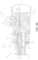
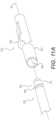
- FIG. 4Ais an enlarged cross-sectional side view of device 10 in a detached configuration, whereby handle 50 is decoupled from catheter 70.
- FIG. 4Bshows device 10 as attached, whereby handle 50 is coupled to catheter 70.
- Handle 50 and catheter 70can be configured for releasable coupling.
- distal end 55 of handle 50 and proximal end 75 of catheter 70can be releasably coupled.
- Distal end 55can include a lumen 82 configured to receive proximal end 75.
- handle 50 and catheter 70could couple using a bayonet connection, a threaded connection, or other type of mechanical coupling.
- FIGs. 4A and 4Bshow securing member 60 as part of distal end 55 of handle 50.
- Securing member 60could be part of proximal end 75 of catheter 70 or could connect separately to handle 50 and catheter 70. While handle 50 is shown with one handle control member 250 and catheter 70 is shown with one catheter control member 255, handle 50 and catheter 70 could include multiple control members 250, 255.
- Securing member 60can be moved to releasably couple a plurality of handle control members 250 and a plurality of catheter control member 255.
- Securing member 60can be configured to move relative to handle 50 or catheter 70.
- securing member 60can move rotationally or longitudinally relative to handle 50.
- securing member 60may move distally from a first position 62 (as shown in FIG. 4A ) to a second position 64 (as shown in FIG. 4B ).
- Handle control member 250may remain in a fixed position relative to handle 50 as securing member 60 is moved from first position 62 to second position 64.
- Securing member 60can also move proximally from second position 64 to first position 62.
- Such movementscan couple and decouple handle 50 and catheter 70.
- Various other types of movement or positioning of securing member 60are also contemplated, such as, for example, longitudinal and rotational movement.
- Control members 250, 255can be configured for releasable coupling.
- control members 250, 255can each include one or more attachment members configured for releasable coupling.
- handle control member 250can include an attachment member 252 and catheter control member 255 can include a corresponding attachment member 256.
- handle control member 250could include attachment member 256 and catheter control member 255 could include corresponding attachment member 252.
- Attachment member 252 and corresponding attachment member 256can be configured to releasably couple to each other.
- Various types of attachment members 252, 256are contemplated. Some may couple using straight-line attachment, such as, for example, as shown in FIGs. 4A and 4B .
- proximal end 75 of catheter 70may be positioned adjacent to distal end 55 of handle 50.
- Securing member 60may initially be in first position 62 such that attachment member 252 can be located within lumen 82, as shown in FIG. 4A .
- Attachment member 252 and corresponding attachment member 256may be aligned based on complementary shapes of attachment members 252, 256, complementary shapes of distal end 75 and lumen 82, or one or more alignment features (not shown).
- a first attachment member 252could have a first shape configured to couple with only a first attachment member 256
- a second attachment member 252could have a second shape different to the first shape and configured to couple with only a second attachment member 256.
- Proximal end 75can then be moved proximally within lumen 82 to locate attachment member 252 within corresponding attachment member 256.
- a retaining member 85may be configured to generally maintain a position of attachment member 252 relative to lumen 82. Retaining member 85 may be necessary to ensure that attachment member 252 is not inadvertently moved proximally by the proximal movement of distal end 75. If attachment member 252 is inadvertently moved proximally, attachment members 252, 256 may not properly engage.
- retaining member 85can be biased to apply a tensile force to attachment member 252 to limit the movement of attachment member 252.
- the tensile force applied to attachment member 252may be sufficient to maintain a position of attachment member 252 relative to lumen 82. Such a tensile force should not affect movement of handle control member 250.
- Retaining member 85can include a spring, a button, a lever, a latch, or similar device. Retaining member 85 could be coupled to attachment members 252, 256 or control members 250, 255. For example, one or more retaining members 85 could be configured to retain a position of one or more handle control members 250 relative to handle 50 or a position of one or more catheter control members 255 relative to catheter 70.
- Retaining member 85can be used for any connection described herein. Such a mechanism may reduce slack and/or lock elements to be connected or disconnected.
- Various mechanism to tension and lock elementscan include hook and loop, ball and slot, tab and hole, or threaded connections.
- proximal movement of retaining member 85may be limited.
- securing member 60could include a stop feature 87 configured to limit proximal movement of retaining member 85.
- Stop feature 87could include a ledge, a step, or similar structure.
- Control members 250, 255may initially be provided in an untensioned or a relaxed state. Such a state may reduce forces applied to control members 250, 255 to reduce the likelihood that control member 250, 255 could be stretched during storage, shipping, or sterilization. Various systems may be used to untension or tension one or more control members 250, 255.
- catheter control member 255may be located in a lumen 103 extending within proximal end 75 of catheter 70.
- Lumen 103can be shaped and sized to receive catheter control member 255.
- Lumen 103can also include a lumen 102 shaped and sized to receive attachment member 256.
- Lumen 102can form part of lumen 103.
- lumen 102can be located proximal to lumen 103.
- Lumen 103can also be shaped and sized to limit distal movement of attachment member 256.
- proximal end 75can include a transition feature 89 located between lumen 103 and lumen 102.
- Transition feature 89can include a ledge, a step, or similar structure configured to limit distal movement of attachment member 256.
- transition feature 89may limit distal movement of attachment member 256 as attachment members 252, 256 are coupled together.
- Lumen 103could also include a lumen 104 configured to receive attachment member 256 following coupling of attachment members 252, 256. As shown in FIG. 4B , coupled attachment members 252, 256 can be moved proximally and distally within lumen 104 to permit the transfer to forces or movement between control members 255, 250.
- Proximal end 75can also include a transition feature 91 located between lumen 102 and lumen 104. In some embodiments, transition feature 91 can include a slope, a taper, or similar structure configured to permit coupling or decoupling of attachment members 252, 256. Attachment members 252, 256 may further include magnetic or geometric locking parts to enhance connections.
- FIG. 4Ashows attachment member 256 in an open configuration 262, wherein attachment member 256 can be located within lumen 102.
- attachment member 252may be moved longitudinally to position attachment member 252 within corresponding attachment member 256. Coupling and decoupling of attachment members 256, 252 may occur by moving attachment members 256, 252 between lumen 102 and lumen 104.
- FIG. 4Bshows attachment member 256 in closed configuration 264, wherein attachment member 256 can be located within lumen 104.
- attachment member 252may be held within corresponding attachment member 256 such that attachment members 252, 256 are coupled to permit transfer of movement or forces between control members 250, 255.
- movement of control members 250, 255may move coupled attachment members 252, 256 within lumen 104.
- Lumen 102can also be configured to maintain catheter control member 255 in an untensioned state.
- attachment member 256may initially be located within lumen 102.
- Lumen 102may be located distal to lumen 104. Moving attachment member 256 proximally from lumen 102 into lumen 104 may function to tension catheter control member 255. Sufficient tension could be applied to ensure appropriate transfer of forces and movement along catheter control member 255.
- Attachment member 256can be biased.
- attachment member 256could be biased in open configuration 262 or closed configuration 264.
- lumen 102can be configured to maintain attachment member 256 in open configuration 262.
- lumen 102could be dimensioned to permit attachment member 256 to assume open configuration 262, as shown in FIG. 4A .
- lumen 102may have an inner diameter sufficient to permit attachment member 256 to assume open configuration 262.
- securing member 60may be moved from first position 62 to second position 64. As shown in FIG. 4B , the movement of securing member 60 to second position 64 may move coupled attachment members 252, 256 into lumen 104.
- Lumen 104can be configured to receive attachment member 256. Lumen 104 can be further configured to provide attachment member 256 in closed configuration 264. For example, lumen 104 may be dimensioned to cause attachment member 256 to assume closed configuration 264. In other embodiments, lumen 104 could include a surface, a protrusion, or other feature configured to provide closed configuration 264. Lumen 104 may apply a compressive force to attachment member 256 to maintain closed configuration 264. Closed configuration 264 can maintain coupling between attachment members 252, 256 by limiting the relative movement between attachment members 252, 256.
- attachment members 252, 256may provide coupling between handle control member 250 and catheter control member 255. This coupling can be released by moving attachment member 256 from lumen 104 to lumen 102.
- moving securing member 60 from second position 64 (as shown in FIG. 4B ) to first position 62 (as shown in FIG. 4A )can move attachment members 256 from lumen 104 to lumen 102.
- Moving attachment member 256 from lumen 104 to lumen 102can transition attachment member 256 from closed configuration 264 to open configuration 262.
- attachment member 252can be decoupled from corresponding attachment member 256.
- Movement of securing member 60may be locked using a locking collar 72.
- Locking collar 72could be configured for lateral movement relative to securing member 60 to limit longitudinal or rotational movement of securing member 60.
- Locking collar 72also could be biased to move in and out of an indentation 73 to lock and unlock securing member 60.
- Other locking systemscould include a lever, a cam lock, a rack and pawl, a knob, a thumb wheel and rack, or a worm gear.
- an end 74 of locking collar 72can engage indentation 73 configured to receive end 74.
- Indentation 73could be mechanically coupled to securing member 60 such that engagement between end 74 and indentation 73 can limit relative movement between securing member 60 and handle 50.
- Other couplings between locking collar 72 and securing member 60are also contemplated.
- locking collar 72could be configured to lock securing member 60 in more than one position. As shown in FIGs. 4A and 4B , locking collar 72 can be configured to lock securing member 60 in second position 64. Locking securing member 60 can ensure that unwanted decoupling of control members 250, 255 does not occur.
- handle 50 and catheter 70can be releasably coupled and locked. Handle 50 and catheter 70 can be coupled to ensure correct alignment of control members 250, 255. Also, handle 50 and catheter 70 can be lockable to limit a relative movement between handle 50 and catheter 70.
- handle 50can include a handle connector 270 and catheter 70 can include a catheter connector 280, whereby connectors 270, 280 are configured to releasably couple.
- Handle connector 270can include a key 92 configured to engage a keyway 274 of catheter connector 280.
- keyway 274can be located on handle connector 270
- key 92can be located on catheter connector 280.
- Other types of connectors 270, 280could include a button, a lever, a cam, a rack and a pawl, a tab, or a thumb wheel and a gear.
- Handle 50 and catheter 70could be connected using a collet, a ball and socket, a % turn fastener, or a magnetic element.
- Handle 50 and catheter 70may be connected using straight-line movement or rotational movement.
- FIG. 5depicts a partial cut away view of handle 50 and catheter 70 configured for straight-line connection.
- distal end 55 of handle 50includes a straight keyway 274 and proximal end 75 of catheter 70 includes key 92.
- Distal end 55also includes a thread 290 configured to threadably engage a threaded ring 292 located on proximal end 75. Threaded ring 292 may be rotatably coupled to proximal end 75.
- Threaded ring 292can be configured to rotate relative to catheter 70 and thread 290. Once key 92 has been moved longitudinally to a position within keyway 274, thread 290 may be rotated relative to threaded ring 292 to lock handle 50 and catheter 70. One or more keys 92 may be configured to engage one or more keyways 274. A latch, a clip, a thumbscrew, or other locking device may also be used to lock handle 50 and catheter 70.
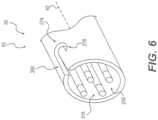
- FIG. 6depicts distal end 55 of handle 50 configured for rotational connection with catheter 70.
- Handle 50 and catheter 70can be connected using a bayonet or a luer lock type connection.
- key 92 located on proximal end 75 of catheter 70may initially be placed within keyway 274 and moved longitudinally within keyway 274.
- Distal end 55 and proximal end 75may then be rotated relative to each other about longitudinal axis 40 to move key 92 tangentially about distal end 55 of handle 50.
- Tangential movement of key 92 within keyway 274can move key 92 to a locking position 278.
- control members 250may each include a rotational attachment member 315.
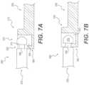
- FIGs. 7A and 7Bdepict rotational attachment member 315 located on handle control member 250 and a corresponding attachment member 340 located on catheter control member 255.
- Each attachment member 315, 340can be configured to releasably couple using rotational movement of handle 50 relative to catheter 70.
- Attachment member 315may also be located on catheter control member 255.
- Attachment member 315can include a cavity 350 configured to receive a head 370 of attachment member 340.
- Attachment member 340can also include a neck 380 configured for placement within a distal opening 330 of cavity 350.
- Head 370can be rotated into cavity 350 via a lateral opening 320 of cavity 350.
- attachment member 340can be moved into cavity 350, as shown in FIGs. 7A, 7B . This can ensure that distal end 55 of handle 50 and proximal end 75 of catheter 70 are coupled together as control members 250, 255 are coupled together.
- FIG. 7Bdepicts attachment member 340 coupled to attachment member 315.
- head 370can be located within cavity 350 to couple attachment members 340, 315. Longitudinal movement of handle control member 250 may be transferred to catheter control member 255 by coupling between head 370 and a wall 385 of attachment member 315.
- Distal opening 330can be configured to receive neck 380 such that longitudinal movement can be transferred between control members 250, 255.
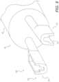
- FIG. 8depicts distal end 55 of handle 50 having attachment members 315 configured for rotational coupling.
- attachment members 315are configured to rotationally couple to corresponding attachment members (not shown). That is, handle 50 can be rotated clockwise relative to catheter 70 (not shown) to couple attachment members 315, 340 and rotated anticlockwise to decouple attachment members 315, 340.
- Lateral openings 330can be oriented to receive multiple corresponding heads 370 simultaneously. Lateral openings 330 could also be configured to receive heads 370 using anticlockwise rotation.
- attachment member 340can include any shape configured to engage cavity 350.
- head 370could be "L" shaped and may pass into cavity 350 via only lateral opening 320.
- attachment member 315may not require distal opening 330 and may only include lateral opening 320.
- One or more openings 320, 330may also be variously shaped to permit passage of head 370 into cavity 350.
- FIGs. 9A and 9Bdepict, respectively, attachment members 340, 315 as uncoupled and attachment members 340, 315 as coupled.
- distal end 55 of handle 50can include a lumen 390 configured to receive attachment member 315.
- Lumen 390can be configured to at least partially maintain coupling between attachment members 340, 315.
- catheter 70can include lumen 390.
- attachment member 315can extend distally beyond a distal-most end 400 of lumen 390.
- Retaining member 85may be configured to limit relative movement between attachment member 315 and lumen 390.
- retaining memberincludes a card 86 configured for placement between cavity 350 and distal-most end 400.
- Card 86could be a plate, or other stopping structure.
- one or more other retaining members 85could also be used.
- attachment member 340With attachment member 315 extending beyond lumen 390, attachment member 340 can be moved rotationally to position head 370 within cavity 350. Once head 370 is properly positioned within cavity 350, retaining member 85 may be removed to permit longitudinal movement of engaged attachment members 315, 340 within lumen 390. As explained above, securing member 60 (not shown) can be configured to move attachment members 315, 340 longitudinally with respect to lumen 390.
- FIG. 9Bdepicts coupled attachment members 315, 340 located within lumen 390.
- Lumen 390can be configured to at least partially limit relative movement between attachment members 340, 315.
- a surface 395 of lumen 390may limit the lateral movement of attachment member 340 relative to attachment member 315.
- Lumen 390can also be configured to limit the movement of head 370 relative to cavity 350. Such limited movement may maintain the coupling between attachment members 340, 315 to permit the transmission of movement or forces between control members 250, 255.
- To decouple attachment members 340, 315they may be moved distally by securing member 60 to beyond distal-most end 400 of lumen 390, then rotated to move heads 370 out of cavities 350.
- FIG. 10depicts another embodiment of lumen 390 showing a straight-line connection between attachment members 252, 256.
- Attachment members 252, 256are shown coupled within lumen 390. Similar to the rotational attachment shown in FIGs. 9A and 9B , attachment member 256 may be initially located distal of distal-most end 400 of lumen 390. Attachment member 256 located outside lumen 390 can be configured to assume open configuration 262 whereby arms 355 extend laterally to permit locating head 375 between open arms 355 (not shown).
- Securing member 60may then move distally (to the left) to move lumen 390 over attachment member 256, as shown in FIG. 10 .
- Lumen 390may be configured to transition attachment member 256 from open configuration 262 to closed configuration 264. Such movement can cause arms 355 to collapse about head 375 to couple attachment members 252, 256.
- retaining member 85can provide a slight tensile force to maintain positioning of attachment member 256 against attachment member 252.
- securing member 60can move proximally (to the right) to move arms 355 out of lumen 390. Once beyond distal-most end 400, arms 355 can reopen to permit removal of head 375 from between arms 355.
- Coupling and decoupling attachment member 252, 256can releasably couple control members 250, 255.
- FIGs. 11A and 11Bdepict another embodiment of lumen 390 showing a straight-line connection between attachment member 252 and corresponding attachment member 510.
- Attachment member 252can be coupled to catheter control member 255 and can include a neck 480 and a head 475.
- Attachment member 510can be coupled to handle control member 250 (not shown) and can include a clip 500 configured to move relative to a tubular member 520.
- Tubular member 520can be configured to receive attachment member 252.
- Clip 500can be configured to assume an open configuration and a closed configuration to releasably couple attachment members 510, 252.
- clip 500may be moved relative to tubular member 520 using securing member 60 (not shown). For example, clip 500 may move along longitudinal axis 40 relative to tubular member 520. This longitudinal movement may cause clip 500 to open or close.
- FIG. 11Bdepicts clip 500 in a closed configuration.
- two clip arms 550can extend through one or more slots 530 of tubular member 520 to engage neck 480 of attachment member 252. Such engagement can limit longitudinal movement between attachment members 510, 252.
- clip 500could be moved longitudinally relative to tubular member 520. The longitudinal movement could cause arms 550 to open as they are removed from within tubular member 520.
- Other types of attachment memberscould also be configured for releasable coupling.
Landscapes
- Health & Medical Sciences (AREA)
- Life Sciences & Earth Sciences (AREA)
- Engineering & Computer Science (AREA)
- Animal Behavior & Ethology (AREA)
- Veterinary Medicine (AREA)
- Public Health (AREA)
- Biomedical Technology (AREA)
- Heart & Thoracic Surgery (AREA)
- General Health & Medical Sciences (AREA)
- Anesthesiology (AREA)
- Hematology (AREA)
- Pulmonology (AREA)
- Biophysics (AREA)
- Surgery (AREA)
- Ophthalmology & Optometry (AREA)
- Nuclear Medicine, Radiotherapy & Molecular Imaging (AREA)
- Medical Informatics (AREA)
- Molecular Biology (AREA)
- Mechanical Engineering (AREA)
- Surgical Instruments (AREA)
- Media Introduction/Drainage Providing Device (AREA)
Description
- Embodiments of the present invention relate to medical devices. In particular, embodiments of the present invention include medical devices having releasable coupling.
- Minimally invasive surgical tools, such as endoscopic and laparoscopic devices, can provide access to surgical sites while minimizing patient trauma. Although the growing capabilities of such therapeutic devices allow physicians to perform an increasing variety of surgeries, further refinements are needed to reduce costs associated with such procedures.
- Some minimally invasive systems include surgical devices that may be sterilized for reuse. Such devices are usually expensive to manufacture and must be designed to withstand multiple sterilization procedures. Similar disposable devices often have limited performance due to the use of cheaper materials and low-cost manufacturing techniques. Endoscopic and laparoscopic devices according to the prior art are described in
US 2009/171147 A1 ,WO 2010/101401 A2 ,US 5860953 A ,US 2008/287862 A1 andUS 6059179 A . - The medical devices described herein overcome at least some of the limitations of the prior art. One aim of at least certain embodiments of the present invention is to reduce costs by providing a medical device that can include some reusable and some disposable components. For example, a medical device could include a reusable handle and a disposable catheter. The reusable handle could be adapted for use with different types of catheters having different end-effectors.
- According to the invention, a medical device as recited in the independent claim is provided. The dependent claims define embodiments of the invention. There is also disclosed a medical device having a longitudinal axis, and including a handle and a catheter. The handle includes a body having a proximal end and a distal end, an actuator moveably coupled to the body, and a handle control member coupled to the actuator, wherein the actuator is configured to move relative to the body to move the handle control member. The catheter includes a shaft having a proximal end and a distal end, wherein the proximal end of the shaft and the distal end of the body are configured for releasable coupling. The catheter also includes a steering section located along the shaft and a catheter control member coupled to the steering section, wherein the catheter control member is configured to move relative to the shaft to move the steering section relative to the longitudinal axis. The medical device also includes a securing member configured to move relative to at least one of the handle and the catheter to releasably couple the handle control member to the catheter control member.
- There is also disclosed a handle configured to releasably couple to a catheter. The handle can include a body configured to releasably couple to the catheter, an actuator moveably coupled to the body and configured to engage a user's hand, and a plurality of handle control members coupled to the actuator, wherein the actuator can be configured to move relative to the body to move at least one of the plurality of handle control members. The handle can also include a securing member configured to move relative to the handle to releasably couple the plurality of handle control members to a plurality of catheter control members.
- There is also disclosed a catheter configured to releasably couple to a handle. The catheter can include a shaft configured to releasably couple to the handle, a steering section located along the shaft, and a plurality of catheter control members coupled to the steering section, wherein each of the plurality of catheter control members can include a first attachment member and can be configured to move relative to the shaft to move the steering section. The catheter can also include a lumen configured to at least partially maintain coupling between the first attachment member and a corresponding attachment member located on a handle control member.
- There is also disclosed a method of assembling a medical device. The method can include moving a handle having a handle control member relative to a catheter having a catheter control member in untensioned state, to engage the handle control member with the catheter control member. The method can also include moving a securing member from a first position to a second position to tension the catheter control member and couple the handle control member to the catheter control member.
- Additional objects and advantages of the invention will be set forth in part in the description which follows, and in part will be obvious from the description, or may be learned by practice of the invention. The objects and advantages of the invention will be realized and attained by means of the elements and combinations particularly pointed out in the appended claims.
- It is to be understood that both the foregoing general description and the following detailed description are exemplary and explanatory only and are not restrictive of the invention, as claimed.
- The accompanying drawings, which are incorporated in and constitute a part of this specification, illustrate embodiments of the invention and together with the description, serve to explain the principles of the invention.
Figure 1 is perspective view of a device in a detached configuration, according to an exemplary embodiment of the invention;Figure 2 is a cut-away perspective view of a handle, according to an exemplary embodiment of the invention;Figure 3A is a side view of an end-effector articulated in three different positions, according to an exemplary embodiment of the invention;Figure 3B is a side view of various end-effectors, according to exemplary embodiments of the invention;Figure 4A is a side view of a detached device, according to an exemplary embodiment of the invention;Figure 4B is a side view of an attached device, according to an exemplary embodiment of the invention;Figure 5 is a partial cut-away perspective view of a detached device, according to an exemplary embodiment of the invention;Figure 6 is a perspective view of a portion of a handle, according to another exemplary embodiment of the invention;Figure 7A is a side view of decoupled attachment members, according to an exemplary embodiment of the invention;Figure 7B is a side view of coupled attachment members, according to an exemplary embodiment of the invention;Figure 8 is a perspective view of a portion of a handle showing attachment members, according to an exemplary embodiment of the invention;Figure 9A is a side view of attachment members in a decoupled configuration, according to an exemplary embodiment of the invention;Figure 9B is a side view of attachment members in a coupled configuration, according to an exemplary embodiment of the invention;Figure 10 is a side view of attachment members in a coupled configuration, according to an exemplary embodiment of the invention;Figure 11A is a side view of attachment members in a decoupled configuration, according to an exemplary embodiment of the invention; andFigure 11B is a side view of attachment members in a coupled configuration, according to an exemplary embodiment of the invention.- Reference will now be made to exemplary embodiments of the invention, examples of which are illustrated in the accompanying drawings. Wherever possible, the same reference numbers will be used throughout the drawings to refer to the same or like parts.
FIG. 1 depicts adevice 10, according to an exemplary embodiment.Device 10 is shown in a detached configuration, whereby a handle 50 is shown separated from acatheter 70. As described herein, handle 50 andcatheter 70 are configured for releasable coupling. Specifically, handle 50 can be attached tocatheter 70 to allow handle 50 to control a movement, actuation, and/or operation ofcatheter 70. Handle 50 can also be detached fromcatheter 70 so thatother catheters 70 may be attached to handle 50.- In some embodiments, handle 50 could be reusable and
catheter 70 could be disposable.Multiple catheters 70, having different end-effectors, could be used interchangeably with a single handle 50. Variousdifferent catheters 70 could be provided together in kit form, wherein eachcatheter 70 has a different end-effector. Device 10 can include a medical device configured for use with a surgical method, including a therapeutic or diagnostic procedure. For example,device 10 can be configured for use with an endoscope, a guide tube, an access catheter, or other type of device configured to access a patient's body.Device 10 may be used for procedures within or adjacent to various body organs, such as, an esophagus, a heart, a stomach, a pelvic area, a bladder, an intestine, or any other portion of a gastrointestinal, urinary, or pulmonary tract.Device 10 may be configured for insertion into a patient's body through an anatomical opening. In other embodiments,device 10 may be used in natural orifice transluminal endoscopic surgery (NOTES) procedures or single incision laparoscopic surgical (SILS) procedures. Accordingly,device 10 can be shaped and sized for placement into a patient via a body cavity or an incision.Device 10 can have a proximal end 20, adistal end 30, and alongitudinal axis 40. Handle 50 can include a distal end 55.Catheter 70 can include aproximal end 75. As shown inFIG. 1 , distal end 55 of handle 50 can be configured to engageproximal end 75 ofcatheter 70. Distal end 55 can also be configured to engage another part ofcatheter 70. Also, another part of handle 50 can be configured to engage toproximal end 75 or another part ofcatheter 70.Catheter 70 can be elongate and may include ashaft 72.Shaft 72 can be flexible and may include one or more lumens (not shown).Catheter 70 can also include a rail 65 configured to moveably couple a frame (not shown) to permit movement ofdevice 10 along or aboutlongitudinal axis 40.Cather 70 can also include asteering section 130.- As shown in
FIG. 1 ,steering section 130 can be located at or neardistal end 30. In other embodiments,steering section 130 can be located anywhere alongshaft 72, or encompass the entire length ofshaft 72. In operation, a user can manipulatesteering section 130 to movedistal end 30 up, down, left, or right. Handle 50 can be configured to control movement ofcatheter 70 in one or more directions relative tolongitudinal axis 40. - Handle 50 can include a
grip 80 moveably coupled to a handle body 90.Grip 80 can be an actuator configured to receive user inputs. For example,grip 80 could be configured to engage a left hand or a right hand of a user.Grip 80 could include a ridge located to separate two adjacent fingers, a surface conforming to part of a human hand, or an aperture configured to receive two or more digits of a user. An exemplary handle is described inU.S. Patent Application Publication No. 2008/0188868 . - Movement of a user's hand may move
grip 80 relative to body 90 to movecatheter 70. Movement of handle 50 along or aboutlongitudinal axis 40 may movecatheter 70 along or aboutlongitudinal axis 40. In other embodiments, handle 50 can include one or more knobs, dials, levers, or other devices configured to controlcatheter 70. - Handle 50 can be configured to provide direct manual user control of
catheter 70. For example, handle 50 can be configured to selectively movecatheter 70 using direct manual user movement. In some embodiments, movement or forces can be mechanically transmitted from handle 50 tocatheter 70 via one ormore control members handle control members 250 may extend within handle 50 and one or morecatheter control members 255 may extend withincatheter 70. Handle 50 may move one ormore control members catheter 70. Control members Control members control members Control members Control members handle control members 250 andcatheter control members 255. That is, either handlecontrol member 250 orcatheter control member 255 could include one or more features or functions ascribed to a particular control member.- As explained below, handle
control members 250 may be releasably coupled tocatheter control members 255, wherein eachhandle control member 250 can be coupled to a correspondingcatheter control member 255. In some embodiments, a securingmember 60 can be configured to move to releasably couple handlecontrol members 250 andcatheter control members 255. FIG. 2 depicts a cut-away perspective view of handle 50, wherein an outer layer of handle 50 has been removed to reveal a frame 200. As shown,grip 80 can be moveably coupled to frame 200 via agrip shaft 210 and atrunion 220.Grip 80 may also be coupled to frame 200 using a hinge, a flexible member, or other type of moveable coupling.Grip 80 can be configured for rotational movement about one or more axes relative to frame 200. For example,grip 80 can be rotated forward or backwards by a user about a lateral axis 230 to provide up or down articulation ofcatheter 70.Grip 80 can be rotated aboutgrip shaft axis 240 to provide left or right articulation ofcatheter 70. Forward or backward movement of a user's hand alonglongitudinal axis 40 may move handle 50 andcatheter 70 forward or backwards alonglongitudinal axis 40. In other embodiments, different movements ofgrip 80 can selectively movecatheter 70.Grip 80 can include atrigger 100 that may be moved to provide actuation of an end-effector located oncatheter 70.Trigger 100 can be positioned ongrip 80 for control by a user's thumb or for finger control.Trigger 100 could also be located on frame 200.- Handle
control members 250 can be coupled totrunion 220,grip 80,grip shaft 210,trigger 100, or similar components such that movement of those components can provide movement ofhandle control members 250 relative to frame 200. For example, trigger 100 can be coupled to handlecontrol member 250 withingrip 80. Such atrigger control member 250 may then pass throughgrip 80, throughgrip shaft 210 and through frame 200. Movingtrigger 100 can move thetrigger control member 250 to selectively actuate an end-effector. Movement of one ormore control members 250 can move one or morecatheter control members 255 to selectively articulate or actuatecatheter 70. - At least part of
handle control member 250 can include a Bowden cable 260. Bowden cable 260 can include asheath 265 surrounding at least part ofhandle control member 250. Relative movement betweensheath 265 and handlecontrol member 250 can transfer compressive or tensile forces. Compressive forces can be transferred throughsheath 265 and tensile forces can be transferred throughhandle control member 250. Tensile forces may also be applied to handlecontrol member 250 by passingcontrol member 250 through part of frame 200. For example, handlecontrol members 250 could pass through aplate 202 or ahub 204. FIG. 3A depicts an end-effector 110 for use withdevice 10. End-effector 110 is shown inFIG. 3A in three different positions: vertical; forty five degrees relative to vertical; and horizontal. End-effector 110 can be moved as indicated byarrows 125 in various directions relative tolongitudinal axis 40 by movement of one or morecatheter control members 255 coupled tosteering section 130.Steering section 130 can include a plurality of articulation links 135.Articulation links 135 can be moved relative to adjacent links via a pivot, flexible connection, sliding engagement, bearing, or other type of joint. One ormore articulation links 135 can be coupled to one or morecatheter control members 255 to control movement ofsteering section 130.- As shown in
FIG. 3A ,steering section 130 can be articulated relative tolongitudinal axis 40. AlthoughFIG. 3A showssteering section 130 moving about 90 degrees fromlongitudinal axis 40,steering section 130 may move through a greater or lesser range of angles relative tolongitudinal axis 40. Further,steering section 130 could be articulated in multiple directions relative tolongitudinal axis 40, such as, for example, in and out of the page. - In some embodiments, end-
effector 110 can include a grasper 115 having one or moremovable jaw members 120 hingedly attached tocatheter 70. Grasper 115 can be configured to grasp tissue.Jaw members 120 may be actuated to move relative to each other. For example,jaw members 120 can be configured to assume anopen configuration 135, a closed configuration 140, or any configuration therebetween. FIG. 3B depicts various end-effectors configured for use withcatheter 70. These and other types of end-effectors may be distally located oncatheter 70 and can be articulated or actuated. One or morecatheter control members 255 can be moved to control articulation ofsteering section 130 and one or more differentcatheter control members 255 can be moved to control actuation of one or more moveable members of end-effector 110.- A
dissector 150 and a pair of scissors 160 can be provided. Bothdissector 150 and scissors 160 can include multiplecatheter control members 255 configured to provide articulation and actuation of both types of end-effectors. End-effector could also include an electrosurgical hook 170, having a hook180 configured to apply ablative energy to tissue. Electrosurgical hook 170 may require articulation and may not require actuation.Catheter 70 could also include a tube 190 configured to provide suction or irrigation to a region distal ofcatheter 70. Tube 190 may not require articulation or actuation. FIG. 4A is an enlarged cross-sectional side view ofdevice 10 in a detached configuration, whereby handle 50 is decoupled fromcatheter 70.FIG. 4B showsdevice 10 as attached, whereby handle 50 is coupled tocatheter 70. Handle 50 andcatheter 70 can be configured for releasable coupling. For example, distal end 55 of handle 50 andproximal end 75 ofcatheter 70 can be releasably coupled. Distal end 55 can include alumen 82 configured to receiveproximal end 75. As explained below, handle 50 andcatheter 70 could couple using a bayonet connection, a threaded connection, or other type of mechanical coupling.FIGs. 4A and4B show securingmember 60 as part of distal end 55 of handle 50. Securingmember 60 could be part ofproximal end 75 ofcatheter 70 or could connect separately to handle 50 andcatheter 70. While handle 50 is shown with onehandle control member 250 andcatheter 70 is shown with onecatheter control member 255, handle 50 andcatheter 70 could includemultiple control members - Securing
member 60 can be moved to releasably couple a plurality ofhandle control members 250 and a plurality ofcatheter control member 255. Securingmember 60 can be configured to move relative to handle 50 orcatheter 70. For example, securingmember 60 can move rotationally or longitudinally relative to handle 50. In particular, securingmember 60 may move distally from a first position 62 (as shown inFIG. 4A ) to a second position 64 (as shown inFIG. 4B ). Handlecontrol member 250 may remain in a fixed position relative to handle 50 as securingmember 60 is moved fromfirst position 62 to second position 64. Securingmember 60 can also move proximally from second position 64 tofirst position 62. Such movements can couple and decouple handle 50 andcatheter 70. Various other types of movement or positioning of securingmember 60 are also contemplated, such as, for example, longitudinal and rotational movement. Control members control members control member 250 can include anattachment member 252 andcatheter control member 255 can include acorresponding attachment member 256. In other embodiments, handlecontrol member 250 could includeattachment member 256 andcatheter control member 255 could includecorresponding attachment member 252.Attachment member 252 andcorresponding attachment member 256 can be configured to releasably couple to each other. Various types ofattachment members FIGs. 4A and4B .- In operation,
proximal end 75 ofcatheter 70 may be positioned adjacent to distal end 55 of handle 50. Securingmember 60 may initially be infirst position 62 such thatattachment member 252 can be located withinlumen 82, as shown inFIG. 4A .Attachment member 252 andcorresponding attachment member 256 may be aligned based on complementary shapes ofattachment members distal end 75 andlumen 82, or one or more alignment features (not shown). For example, afirst attachment member 252 could have a first shape configured to couple with only afirst attachment member 256, and asecond attachment member 252 could have a second shape different to the first shape and configured to couple with only asecond attachment member 256. Proximal end 75 can then be moved proximally withinlumen 82 to locateattachment member 252 withincorresponding attachment member 256. Asdistal end 75 moves proximally, a retainingmember 85 may be configured to generally maintain a position ofattachment member 252 relative to lumen 82. Retainingmember 85 may be necessary to ensure thatattachment member 252 is not inadvertently moved proximally by the proximal movement ofdistal end 75. Ifattachment member 252 is inadvertently moved proximally,attachment members - In some embodiments, retaining
member 85 can be biased to apply a tensile force toattachment member 252 to limit the movement ofattachment member 252. The tensile force applied toattachment member 252 may be sufficient to maintain a position ofattachment member 252 relative to lumen 82. Such a tensile force should not affect movement ofhandle control member 250. - Retaining
member 85 can include a spring, a button, a lever, a latch, or similar device. Retainingmember 85 could be coupled toattachment members control members more retaining members 85 could be configured to retain a position of one or morehandle control members 250 relative to handle 50 or a position of one or morecatheter control members 255 relative tocatheter 70. - Retaining
member 85, or similar biasing, can be used for any connection described herein. Such a mechanism may reduce slack and/or lock elements to be connected or disconnected. Various mechanism to tension and lock elements can include hook and loop, ball and slot, tab and hole, or threaded connections. - In some embodiments, proximal movement of retaining
member 85 may be limited. For example, securingmember 60 could include a stop feature 87 configured to limit proximal movement of retainingmember 85. Stop feature 87 could include a ledge, a step, or similar structure. Control members members member more control members - In some embodiments,
catheter control member 255 may be located in alumen 103 extending withinproximal end 75 ofcatheter 70.Lumen 103 can be shaped and sized to receivecatheter control member 255.Lumen 103 can also include a lumen 102 shaped and sized to receiveattachment member 256. Lumen 102 can form part oflumen 103. For example, lumen 102 can be located proximal tolumen 103.Lumen 103 can also be shaped and sized to limit distal movement ofattachment member 256. - As shown in
FIGs. 4A and4B ,proximal end 75 can include a transition feature 89 located betweenlumen 103 and lumen 102. Transition feature 89 can include a ledge, a step, or similar structure configured to limit distal movement ofattachment member 256. In particular, transition feature 89 may limit distal movement ofattachment member 256 asattachment members Lumen 103 could also include a lumen 104 configured to receiveattachment member 256 following coupling ofattachment members FIG. 4B , coupledattachment members control members Proximal end 75 can also include a transition feature 91 located between lumen 102 and lumen 104. In some embodiments, transition feature 91 can include a slope, a taper, or similar structure configured to permit coupling or decoupling ofattachment members Attachment members FIG. 4A showsattachment member 256 in an open configuration 262, whereinattachment member 256 can be located within lumen 102. In open configuration 262,attachment member 252 may be moved longitudinally to positionattachment member 252 withincorresponding attachment member 256. Coupling and decoupling ofattachment members attachment members FIG. 4B showsattachment member 256 in closed configuration 264, whereinattachment member 256 can be located within lumen 104. In closed configuration 264,attachment member 252 may be held withincorresponding attachment member 256 such thatattachment members control members control members attachment members - Lumen 102 can also be configured to maintain
catheter control member 255 in an untensioned state. For example,attachment member 256 may initially be located within lumen 102. Lumen 102 may be located distal to lumen 104. Movingattachment member 256 proximally from lumen 102 into lumen 104 may function to tensioncatheter control member 255. Sufficient tension could be applied to ensure appropriate transfer of forces and movement alongcatheter control member 255. Attachment member 256 can be biased. For example,attachment member 256 could be biased in open configuration 262 or closed configuration 264. Also, lumen 102 can be configured to maintainattachment member 256 in open configuration 262. For example, lumen 102 could be dimensioned to permitattachment member 256 to assume open configuration 262, as shown inFIG. 4A . Specifically, lumen 102 may have an inner diameter sufficient to permitattachment member 256 to assume open configuration 262.- Once
proximal end 75 ofcatheter 70 is located withinlumen 82 of handle 50 andattachment member 252 is located withincorresponding attachment member 256, securingmember 60 may be moved fromfirst position 62 to second position 64. As shown inFIG. 4B , the movement of securingmember 60 to second position 64 may move coupledattachment members - Lumen 104 can be configured to receive
attachment member 256. Lumen 104 can be further configured to provideattachment member 256 in closed configuration 264. For example, lumen 104 may be dimensioned to causeattachment member 256 to assume closed configuration 264. In other embodiments, lumen 104 could include a surface, a protrusion, or other feature configured to provide closed configuration 264. Lumen 104 may apply a compressive force toattachment member 256 to maintain closed configuration 264. Closed configuration 264 can maintain coupling betweenattachment members attachment members - In closed configuration 264,
attachment members handle control member 250 andcatheter control member 255. This coupling can be released by movingattachment member 256 from lumen 104 to lumen 102. For example, moving securingmember 60 from second position 64 (as shown inFIG. 4B ) to first position 62 (as shown inFIG. 4A ) can moveattachment members 256 from lumen 104 to lumen 102. Movingattachment member 256 from lumen 104 to lumen 102 can transitionattachment member 256 from closed configuration 264 to open configuration 262. In open configuration 262,attachment member 252 can be decoupled from correspondingattachment member 256. - Movement of securing
member 60 may be locked using alocking collar 72. Lockingcollar 72 could be configured for lateral movement relative to securingmember 60 to limit longitudinal or rotational movement of securingmember 60. Lockingcollar 72 also could be biased to move in and out of anindentation 73 to lock and unlock securingmember 60. Other locking systems could include a lever, a cam lock, a rack and pawl, a knob, a thumb wheel and rack, or a worm gear. - As shown in
FIG. 4B , anend 74 of lockingcollar 72 can engageindentation 73 configured to receiveend 74.Indentation 73 could be mechanically coupled to securingmember 60 such that engagement betweenend 74 andindentation 73 can limit relative movement between securingmember 60 and handle 50. Other couplings between lockingcollar 72 and securingmember 60 are also contemplated. - In some embodiments, locking
collar 72 could be configured to lock securingmember 60 in more than one position. As shown inFIGs. 4A and4B , lockingcollar 72 can be configured to lock securingmember 60 in second position 64. Locking securingmember 60 can ensure that unwanted decoupling ofcontrol members - As well as
control members catheter 70 can be releasably coupled and locked. Handle 50 andcatheter 70 can be coupled to ensure correct alignment ofcontrol members catheter 70 can be lockable to limit a relative movement between handle 50 andcatheter 70. - As shown in
FIGs. 4A and4B , handle 50 can include ahandle connector 270 andcatheter 70 can include acatheter connector 280, wherebyconnectors Handle connector 270 can include a key 92 configured to engage akeyway 274 ofcatheter connector 280. Alternatively,keyway 274 can be located onhandle connector 270 and key 92 can be located oncatheter connector 280. Other types ofconnectors catheter 70 could be connected using a collet, a ball and socket, a % turn fastener, or a magnetic element. - Handle 50 and
catheter 70 may be connected using straight-line movement or rotational movement.FIG. 5 depicts a partial cut away view of handle 50 andcatheter 70 configured for straight-line connection. As shown, distal end 55 of handle 50 includes astraight keyway 274 andproximal end 75 ofcatheter 70 includes key 92. Distal end 55 also includes a thread 290 configured to threadably engage a threaded ring 292 located onproximal end 75. Threaded ring 292 may be rotatably coupled toproximal end 75. - Threaded ring 292 can be configured to rotate relative to
catheter 70 and thread 290. Once key 92 has been moved longitudinally to a position withinkeyway 274, thread 290 may be rotated relative to threaded ring 292 to lock handle 50 andcatheter 70. One or more keys 92 may be configured to engage one ormore keyways 274. A latch, a clip, a thumbscrew, or other locking device may also be used to lock handle 50 andcatheter 70. FIG. 6 depicts distal end 55 of handle 50 configured for rotational connection withcatheter 70. Handle 50 andcatheter 70 can be connected using a bayonet or a luer lock type connection. In operation, key 92 located onproximal end 75 ofcatheter 70 may initially be placed withinkeyway 274 and moved longitudinally withinkeyway 274. Distal end 55 andproximal end 75 may then be rotated relative to each other aboutlongitudinal axis 40 to move key 92 tangentially about distal end 55 of handle 50. Tangential movement of key 92 withinkeyway 274 can move key 92 to a locking position 278. When key 92 is located at locking position 278, a compressive force between handle 50 andcatheter 70 may be required to release key 92 fromkeyway 274. To permit rotational coupling of handle 50 andcatheter 70,control members 250 may each include arotational attachment member 315.FIGs. 7A and 7B depictrotational attachment member 315 located onhandle control member 250 and acorresponding attachment member 340 located oncatheter control member 255. Eachattachment member catheter 70.Attachment member 315 may also be located oncatheter control member 255.Attachment member 315 can include a cavity 350 configured to receive ahead 370 ofattachment member 340.Attachment member 340 can also include aneck 380 configured for placement within adistal opening 330 of cavity 350.Head 370 can be rotated into cavity 350 via alateral opening 320 of cavity 350. For example, as key 92 is moved into locking position 278 ofkeyway 274,attachment member 340 can be moved into cavity 350, as shown inFIGs. 7A, 7B . This can ensure that distal end 55 of handle 50 andproximal end 75 ofcatheter 70 are coupled together ascontrol members FIG. 7B depictsattachment member 340 coupled toattachment member 315. As shown,head 370 can be located within cavity 350 to coupleattachment members handle control member 250 may be transferred tocatheter control member 255 by coupling betweenhead 370 and awall 385 ofattachment member 315.Distal opening 330 can be configured to receiveneck 380 such that longitudinal movement can be transferred betweencontrol members FIG. 8 depicts distal end 55 of handle 50 havingattachment members 315 configured for rotational coupling. As shown,attachment members 315 are configured to rotationally couple to corresponding attachment members (not shown). That is, handle 50 can be rotated clockwise relative to catheter 70 (not shown) tocouple attachment members attachment members Lateral openings 330 can be oriented to receive multiplecorresponding heads 370 simultaneously.Lateral openings 330 could also be configured to receiveheads 370 using anticlockwise rotation.- It is also contemplated that
attachment member 340 can include any shape configured to engage cavity 350. For example,head 370 could be "L" shaped and may pass into cavity 350 via onlylateral opening 320. In such an embodiment,attachment member 315 may not requiredistal opening 330 and may only includelateral opening 320. One ormore openings head 370 into cavity 350. FIGs. 9A and9B depict, respectively,attachment members attachment members attachment member 315. Lumen 390 can be configured to at least partially maintain coupling betweenattachment members catheter 70 can include lumen 390.- Initially,
attachment member 315 can extend distally beyond adistal-most end 400 of lumen 390. Retainingmember 85 may be configured to limit relative movement betweenattachment member 315 and lumen 390. As shown, retaining member includes acard 86 configured for placement between cavity 350 anddistal-most end 400.Card 86 could be a plate, or other stopping structure. As previously explained, one or more other retainingmembers 85 could also be used. - With
attachment member 315 extending beyond lumen 390,attachment member 340 can be moved rotationally to positionhead 370 within cavity 350. Oncehead 370 is properly positioned within cavity 350, retainingmember 85 may be removed to permit longitudinal movement of engagedattachment members attachment members FIG. 9B depicts coupledattachment members attachment members surface 395 of lumen 390 may limit the lateral movement ofattachment member 340 relative toattachment member 315. Lumen 390 can also be configured to limit the movement ofhead 370 relative to cavity 350. Such limited movement may maintain the coupling betweenattachment members control members attachment members member 60 to beyonddistal-most end 400 of lumen 390, then rotated to moveheads 370 out of cavities 350.FIG. 10 depicts another embodiment of lumen 390 showing a straight-line connection betweenattachment members Attachment members FIGs. 9A and9B ,attachment member 256 may be initially located distal ofdistal-most end 400 of lumen 390.Attachment member 256 located outside lumen 390 can be configured to assume open configuration 262 whereby arms 355 extend laterally to permit locatinghead 375 between open arms 355 (not shown).- Securing
member 60 may then move distally (to the left) to move lumen 390 overattachment member 256, as shown inFIG. 10 . Lumen 390 may be configured to transitionattachment member 256 from open configuration 262 to closed configuration 264. Such movement can cause arms 355 to collapse abouthead 375 to coupleattachment members member 60, retainingmember 85 can provide a slight tensile force to maintain positioning ofattachment member 256 againstattachment member 252. - To decouple
attachment members member 60 can move proximally (to the right) to move arms 355 out of lumen 390. Once beyonddistal-most end 400, arms 355 can reopen to permit removal ofhead 375 from between arms 355. Coupling anddecoupling attachment member control members FIGs. 11A and11B depict another embodiment of lumen 390 showing a straight-line connection betweenattachment member 252 andcorresponding attachment member 510.Attachment member 252 can be coupled tocatheter control member 255 and can include aneck 480 and ahead 475.Attachment member 510 can be coupled to handle control member 250 (not shown) and can include a clip 500 configured to move relative to a tubular member 520. Tubular member 520 can be configured to receiveattachment member 252.- Clip 500 can be configured to assume an open configuration and a closed configuration to releasably
couple attachment members longitudinal axis 40 relative to tubular member 520. This longitudinal movement may cause clip 500 to open or close. FIG. 11B depicts clip 500 in a closed configuration. As shown, two clip arms 550 can extend through one ormore slots 530 of tubular member 520 to engageneck 480 ofattachment member 252. Such engagement can limit longitudinal movement betweenattachment members attachment members - Other embodiments of the invention will be apparent to those skilled in the art from consideration of the specification and practice of the invention disclosed herein. It is intended that the specification and examples be considered as exemplary only, with a true scope of the invention being indicated by the following claims.
Claims (13)
- A medical device comprising:a handle body (90) having a proximal end and a distal end (55), the handle body (90) configured to releasably couple to a shaft (72);an actuator (80; 100) coupled to the handle body (90); anda handle control member (250) coupled to the actuator (80; 100), wherein the actuator (80; 100) is configured to move relative to the handle body (90) to move the handle control member (250) relative to the handle body (90), and wherein a distal end of the handle control member (250) includes an attachment member (252; 256; 315; 510) for releasably coupling the distal end of the handle control member (250) to a proximal end of a shaft control member (255) within the shaft (72),characterized in thatthe handle control member (250) includes a retaining member (85), wherein the retaining member (85) is configured to transition between a first configuration and a second configuration to reduce slack of the handle control member (250) and the shaft control member (255), and wherein the retaining member (85) is biased into the first configuration, wherein the retaining member (85) includes at least one of a spring, a button, a lever, or a latch.
- The medical device of claim 1, wherein the handle control member (250) includes at least one of a cable, a wire, a thread, a coil, or a ribbon.
- The medical device of claim 1 or claim 2, wherein the actuator (80; 100) includes at least one of a knob, a dial, a lever, or a rotatable grip.
- The medical device of any one of the preceding claims, wherein the attachment member (252; 256; 315; 510) (a) includes a head (370) extending radially outward from a longitudinal axis of the handle control member (250) or (b) defines a cavity (350; 390).
- The medical device of any one of the preceding claims, further comprising the shaft (72), wherein the attachment member (252; 256; 315; 510) is a first attachment member (252; 256; 315; 510), wherein the shaft control member (255) includes a second attachment member (256; 252; 340; 375) at a proximal end of the shaft control member (255).
- The medical device of claim 5, wherein one of the first attachment member (252; 256; 315; 510) or the second attachment member (256; 252; 340; 375) includes a head (370) and another of the first attachment member (252; 256; 315; 510) or the second attachment member (256; 252; 340; 375) defines a cavity (350; 390) for receiving the head (370).
- The medical device of claim 6, wherein the cavity (350; 390) is configured to be coupled to the protrusion via (a) axial movement of the first attachment member (252; 256; 315; 510) relative to the second attachment member (256; 252; 340; 375), (b) rotational movement of the head (370)relative to the cavity (350), or (c) a clip (500) configured to selectively engage at least one of the first and second attachment members.
- The medical device of any one of the preceding claims, further comprising a lock (60; 92; 270) positioned at the distal end (55) of the handle body (90), wherein the lock (60; 92; 270) is movable relative to the handle body (90), and wherein the lock (60; 92; 270) is configured to secure the shaft (72) to the handle body (90).
- The medical device of any one of the preceding claims, wherein the distal end of the handle control member (250) is proximal of the distal end (55) of the handle body (90).
- The medical device of claim any one of claims 1 to 4, wherein the handle control member (250) is a first handle control member (250), the attachment member (252; 256; 315; 510) is a first attachment member (252; 256; 315; 510), and the shaft control member (255) is a first shaft control member (255), further comprising a second handle control member (250) terminating at a distal end, wherein the distal end of the second handle control member (250) includes a second attachment member (252; 256; 315; 510) for releasably coupling the distal end of the second handle control member (250) to a proximal end of a second shaft control member (255) within the shaft (72).
- The medical device of claim 10, wherein the first attachment member (252; 256; 315; 510) has a first shape to complement the first shaft control member (255), and wherein the second attachment member (252; 256; 315; 510) has a second shape, different from the first shape, to complement the second shaft control member (255).
- The medical device of any one of claims 1 to 4, wherein the device is a handle (50) configured to releasably couple to a catheter (70).
- The medical device of any one of the preceding claims, wherein the shaft (72) is a catheter shaft of a catheter (70) and the handle body (90) is configured to releasably couple to the catheter (70).
Priority Applications (1)
| Application Number | Priority Date | Filing Date | Title |
|---|---|---|---|
| EP23191813.7AEP4268877A3 (en) | 2011-01-31 | 2012-01-27 | Medical devices having releasable coupling |
Applications Claiming Priority (3)
| Application Number | Priority Date | Filing Date | Title |
|---|---|---|---|
| US201161438149P | 2011-01-31 | 2011-01-31 | |
| PCT/US2012/022837WO2012106187A1 (en) | 2011-01-31 | 2012-01-27 | Medical devices having releasable coupling |
| EP12702156.6AEP2670317B1 (en) | 2011-01-31 | 2012-01-27 | Medical devices having releasable coupling |
Related Parent Applications (1)
| Application Number | Title | Priority Date | Filing Date |
|---|---|---|---|
| EP12702156.6ADivisionEP2670317B1 (en) | 2011-01-31 | 2012-01-27 | Medical devices having releasable coupling |
Related Child Applications (2)
| Application Number | Title | Priority Date | Filing Date |
|---|---|---|---|
| EP23191813.7ADivision-IntoEP4268877A3 (en) | 2011-01-31 | 2012-01-27 | Medical devices having releasable coupling |
| EP23191813.7ADivisionEP4268877A3 (en) | 2011-01-31 | 2012-01-27 | Medical devices having releasable coupling |
Publications (2)
| Publication Number | Publication Date |
|---|---|
| EP3964146A1 EP3964146A1 (en) | 2022-03-09 |
| EP3964146B1true EP3964146B1 (en) | 2023-10-18 |
Family
ID=45561161
Family Applications (3)
| Application Number | Title | Priority Date | Filing Date |
|---|---|---|---|
| EP21196279.0AActiveEP3964146B1 (en) | 2011-01-31 | 2012-01-27 | Medical devices having releasable coupling |
| EP12702156.6AActiveEP2670317B1 (en) | 2011-01-31 | 2012-01-27 | Medical devices having releasable coupling |
| EP23191813.7AWithdrawnEP4268877A3 (en) | 2011-01-31 | 2012-01-27 | Medical devices having releasable coupling |
Family Applications After (2)
| Application Number | Title | Priority Date | Filing Date |
|---|---|---|---|
| EP12702156.6AActiveEP2670317B1 (en) | 2011-01-31 | 2012-01-27 | Medical devices having releasable coupling |
| EP23191813.7AWithdrawnEP4268877A3 (en) | 2011-01-31 | 2012-01-27 | Medical devices having releasable coupling |
Country Status (3)
| Country | Link |
|---|---|
| US (6) | US8777898B2 (en) |
| EP (3) | EP3964146B1 (en) |
| WO (1) | WO2012106187A1 (en) |
Families Citing this family (459)
| Publication number | Priority date | Publication date | Assignee | Title |
|---|---|---|---|---|
| US20070084897A1 (en) | 2003-05-20 | 2007-04-19 | Shelton Frederick E Iv | Articulating surgical stapling instrument incorporating a two-piece e-beam firing mechanism |
| US9060770B2 (en) | 2003-05-20 | 2015-06-23 | Ethicon Endo-Surgery, Inc. | Robotically-driven surgical instrument with E-beam driver |
| US9072535B2 (en) | 2011-05-27 | 2015-07-07 | Ethicon Endo-Surgery, Inc. | Surgical stapling instruments with rotatable staple deployment arrangements |
| US11890012B2 (en) | 2004-07-28 | 2024-02-06 | Cilag Gmbh International | Staple cartridge comprising cartridge body and attached support |
| US11998198B2 (en) | 2004-07-28 | 2024-06-04 | Cilag Gmbh International | Surgical stapling instrument incorporating a two-piece E-beam firing mechanism |
| US8215531B2 (en) | 2004-07-28 | 2012-07-10 | Ethicon Endo-Surgery, Inc. | Surgical stapling instrument having a medical substance dispenser |
| US7934630B2 (en) | 2005-08-31 | 2011-05-03 | Ethicon Endo-Surgery, Inc. | Staple cartridges for forming staples having differing formed staple heights |
| US11484312B2 (en) | 2005-08-31 | 2022-11-01 | Cilag Gmbh International | Staple cartridge comprising a staple driver arrangement |
| US10159482B2 (en) | 2005-08-31 | 2018-12-25 | Ethicon Llc | Fastener cartridge assembly comprising a fixed anvil and different staple heights |
| US7669746B2 (en) | 2005-08-31 | 2010-03-02 | Ethicon Endo-Surgery, Inc. | Staple cartridges for forming staples having differing formed staple heights |
| US9237891B2 (en) | 2005-08-31 | 2016-01-19 | Ethicon Endo-Surgery, Inc. | Robotically-controlled surgical stapling devices that produce formed staples having different lengths |
| US11246590B2 (en) | 2005-08-31 | 2022-02-15 | Cilag Gmbh International | Staple cartridge including staple drivers having different unfired heights |
| US20070106317A1 (en) | 2005-11-09 | 2007-05-10 | Shelton Frederick E Iv | Hydraulically and electrically actuated articulation joints for surgical instruments |
| US11224427B2 (en) | 2006-01-31 | 2022-01-18 | Cilag Gmbh International | Surgical stapling system including a console and retraction assembly |
| US7845537B2 (en) | 2006-01-31 | 2010-12-07 | Ethicon Endo-Surgery, Inc. | Surgical instrument having recording capabilities |
| US20110295295A1 (en) | 2006-01-31 | 2011-12-01 | Ethicon Endo-Surgery, Inc. | Robotically-controlled surgical instrument having recording capabilities |
| US8708213B2 (en) | 2006-01-31 | 2014-04-29 | Ethicon Endo-Surgery, Inc. | Surgical instrument having a feedback system |
| US20120292367A1 (en) | 2006-01-31 | 2012-11-22 | Ethicon Endo-Surgery, Inc. | Robotically-controlled end effector |
| US20110024477A1 (en) | 2009-02-06 | 2011-02-03 | Hall Steven G | Driven Surgical Stapler Improvements |
| US11793518B2 (en) | 2006-01-31 | 2023-10-24 | Cilag Gmbh International | Powered surgical instruments with firing system lockout arrangements |
| US8820603B2 (en) | 2006-01-31 | 2014-09-02 | Ethicon Endo-Surgery, Inc. | Accessing data stored in a memory of a surgical instrument |
| US7753904B2 (en) | 2006-01-31 | 2010-07-13 | Ethicon Endo-Surgery, Inc. | Endoscopic surgical instrument with a handle that can articulate with respect to the shaft |
| US11278279B2 (en) | 2006-01-31 | 2022-03-22 | Cilag Gmbh International | Surgical instrument assembly |
| US8186555B2 (en) | 2006-01-31 | 2012-05-29 | Ethicon Endo-Surgery, Inc. | Motor-driven surgical cutting and fastening instrument with mechanical closure system |
| US8992422B2 (en) | 2006-03-23 | 2015-03-31 | Ethicon Endo-Surgery, Inc. | Robotically-controlled endoscopic accessory channel |
| US8322455B2 (en) | 2006-06-27 | 2012-12-04 | Ethicon Endo-Surgery, Inc. | Manually driven surgical cutting and fastening instrument |
| US10568652B2 (en) | 2006-09-29 | 2020-02-25 | Ethicon Llc | Surgical staples having attached drivers of different heights and stapling instruments for deploying the same |
| US7506791B2 (en) | 2006-09-29 | 2009-03-24 | Ethicon Endo-Surgery, Inc. | Surgical stapling instrument with mechanical mechanism for limiting maximum tissue compression |
| US11980366B2 (en) | 2006-10-03 | 2024-05-14 | Cilag Gmbh International | Surgical instrument |
| US8632535B2 (en) | 2007-01-10 | 2014-01-21 | Ethicon Endo-Surgery, Inc. | Interlock and surgical instrument including same |
| US11291441B2 (en) | 2007-01-10 | 2022-04-05 | Cilag Gmbh International | Surgical instrument with wireless communication between control unit and remote sensor |
| US8684253B2 (en) | 2007-01-10 | 2014-04-01 | Ethicon Endo-Surgery, Inc. | Surgical instrument with wireless communication between a control unit of a robotic system and remote sensor |
| US8652120B2 (en) | 2007-01-10 | 2014-02-18 | Ethicon Endo-Surgery, Inc. | Surgical instrument with wireless communication between control unit and sensor transponders |
| US11039836B2 (en) | 2007-01-11 | 2021-06-22 | Cilag Gmbh International | Staple cartridge for use with a surgical stapling instrument |
| US20080169333A1 (en) | 2007-01-11 | 2008-07-17 | Shelton Frederick E | Surgical stapler end effector with tapered distal end |
| US7673782B2 (en) | 2007-03-15 | 2010-03-09 | Ethicon Endo-Surgery, Inc. | Surgical stapling instrument having a releasable buttress material |
| US8893946B2 (en) | 2007-03-28 | 2014-11-25 | Ethicon Endo-Surgery, Inc. | Laparoscopic tissue thickness and clamp load measuring devices |
| US8931682B2 (en) | 2007-06-04 | 2015-01-13 | Ethicon Endo-Surgery, Inc. | Robotically-controlled shaft based rotary drive systems for surgical instruments |
| US11564682B2 (en) | 2007-06-04 | 2023-01-31 | Cilag Gmbh International | Surgical stapler device |
| US7753245B2 (en) | 2007-06-22 | 2010-07-13 | Ethicon Endo-Surgery, Inc. | Surgical stapling instruments |
| US11849941B2 (en) | 2007-06-29 | 2023-12-26 | Cilag Gmbh International | Staple cartridge having staple cavities extending at a transverse angle relative to a longitudinal cartridge axis |
| US7866527B2 (en) | 2008-02-14 | 2011-01-11 | Ethicon Endo-Surgery, Inc. | Surgical stapling apparatus with interlockable firing system |
| US11986183B2 (en) | 2008-02-14 | 2024-05-21 | Cilag Gmbh International | Surgical cutting and fastening instrument comprising a plurality of sensors to measure an electrical parameter |
| US7819298B2 (en) | 2008-02-14 | 2010-10-26 | Ethicon Endo-Surgery, Inc. | Surgical stapling apparatus with control features operable with one hand |
| US8573465B2 (en) | 2008-02-14 | 2013-11-05 | Ethicon Endo-Surgery, Inc. | Robotically-controlled surgical end effector system with rotary actuated closure systems |
| JP5410110B2 (en) | 2008-02-14 | 2014-02-05 | エシコン・エンド−サージェリィ・インコーポレイテッド | Surgical cutting / fixing instrument with RF electrode |
| US8758391B2 (en) | 2008-02-14 | 2014-06-24 | Ethicon Endo-Surgery, Inc. | Interchangeable tools for surgical instruments |
| US9179912B2 (en) | 2008-02-14 | 2015-11-10 | Ethicon Endo-Surgery, Inc. | Robotically-controlled motorized surgical cutting and fastening instrument |
| US8636736B2 (en) | 2008-02-14 | 2014-01-28 | Ethicon Endo-Surgery, Inc. | Motorized surgical cutting and fastening instrument |
| US9585657B2 (en) | 2008-02-15 | 2017-03-07 | Ethicon Endo-Surgery, Llc | Actuator for releasing a layer of material from a surgical end effector |
| US11272927B2 (en) | 2008-02-15 | 2022-03-15 | Cilag Gmbh International | Layer arrangements for surgical staple cartridges |
| US9005230B2 (en) | 2008-09-23 | 2015-04-14 | Ethicon Endo-Surgery, Inc. | Motorized surgical instrument |
| US11648005B2 (en) | 2008-09-23 | 2023-05-16 | Cilag Gmbh International | Robotically-controlled motorized surgical instrument with an end effector |
| US9386983B2 (en) | 2008-09-23 | 2016-07-12 | Ethicon Endo-Surgery, Llc | Robotically-controlled motorized surgical instrument |
| US8210411B2 (en) | 2008-09-23 | 2012-07-03 | Ethicon Endo-Surgery, Inc. | Motor-driven surgical cutting instrument |
| US8608045B2 (en) | 2008-10-10 | 2013-12-17 | Ethicon Endo-Sugery, Inc. | Powered surgical cutting and stapling apparatus with manually retractable firing system |
| US8517239B2 (en) | 2009-02-05 | 2013-08-27 | Ethicon Endo-Surgery, Inc. | Surgical stapling instrument comprising a magnetic element driver |
| RU2525225C2 (en) | 2009-02-06 | 2014-08-10 | Этикон Эндо-Серджери, Инк. | Improvement of drive surgical suturing instrument |
| US8444036B2 (en) | 2009-02-06 | 2013-05-21 | Ethicon Endo-Surgery, Inc. | Motor driven surgical fastener device with mechanisms for adjusting a tissue gap within the end effector |
| US8220688B2 (en) | 2009-12-24 | 2012-07-17 | Ethicon Endo-Surgery, Inc. | Motor-driven surgical cutting instrument with electric actuator directional control assembly |
| US8851354B2 (en) | 2009-12-24 | 2014-10-07 | Ethicon Endo-Surgery, Inc. | Surgical cutting instrument that analyzes tissue thickness |
| US8783543B2 (en) | 2010-07-30 | 2014-07-22 | Ethicon Endo-Surgery, Inc. | Tissue acquisition arrangements and methods for surgical stapling devices |
| US9629814B2 (en) | 2010-09-30 | 2017-04-25 | Ethicon Endo-Surgery, Llc | Tissue thickness compensator configured to redistribute compressive forces |
| US9788834B2 (en) | 2010-09-30 | 2017-10-17 | Ethicon Llc | Layer comprising deployable attachment members |
| US10945731B2 (en) | 2010-09-30 | 2021-03-16 | Ethicon Llc | Tissue thickness compensator comprising controlled release and expansion |
| US12213666B2 (en) | 2010-09-30 | 2025-02-04 | Cilag Gmbh International | Tissue thickness compensator comprising layers |
| US11812965B2 (en) | 2010-09-30 | 2023-11-14 | Cilag Gmbh International | Layer of material for a surgical end effector |
| US9232941B2 (en) | 2010-09-30 | 2016-01-12 | Ethicon Endo-Surgery, Inc. | Tissue thickness compensator comprising a reservoir |
| US9364233B2 (en) | 2010-09-30 | 2016-06-14 | Ethicon Endo-Surgery, Llc | Tissue thickness compensators for circular surgical staplers |
| US11925354B2 (en) | 2010-09-30 | 2024-03-12 | Cilag Gmbh International | Staple cartridge comprising staples positioned within a compressible portion thereof |
| US9016542B2 (en) | 2010-09-30 | 2015-04-28 | Ethicon Endo-Surgery, Inc. | Staple cartridge comprising compressible distortion resistant components |
| US9351730B2 (en) | 2011-04-29 | 2016-05-31 | Ethicon Endo-Surgery, Llc | Tissue thickness compensator comprising channels |
| US11298125B2 (en) | 2010-09-30 | 2022-04-12 | Cilag Gmbh International | Tissue stapler having a thickness compensator |
| US9386988B2 (en) | 2010-09-30 | 2016-07-12 | Ethicon End-Surgery, LLC | Retainer assembly including a tissue thickness compensator |
| US8695866B2 (en) | 2010-10-01 | 2014-04-15 | Ethicon Endo-Surgery, Inc. | Surgical instrument having a power control circuit |
| EP3964146B1 (en)* | 2011-01-31 | 2023-10-18 | Boston Scientific Scimed Inc. | Medical devices having releasable coupling |
| AU2012250197B2 (en) | 2011-04-29 | 2017-08-10 | Ethicon Endo-Surgery, Inc. | Staple cartridge comprising staples positioned within a compressible portion thereof |
| US11207064B2 (en) | 2011-05-27 | 2021-12-28 | Cilag Gmbh International | Automated end effector component reloading system for use with a robotic system |
| JP6174017B2 (en) | 2011-06-10 | 2017-08-02 | ボード オブ リージェンツ オブ ザ ユニバーシティ オブ ネブラスカ | In vivo vascular seal end effector and in vivo robotic device |
| US9114232B2 (en)* | 2011-12-30 | 2015-08-25 | St. Jude Medical, Atrial Fibrillation Division, Inc. | Catheter for manual and remote manipulation |
| US9044230B2 (en) | 2012-02-13 | 2015-06-02 | Ethicon Endo-Surgery, Inc. | Surgical cutting and fastening instrument with apparatus for determining cartridge and firing motion status |
| JP6224070B2 (en) | 2012-03-28 | 2017-11-01 | エシコン・エンド−サージェリィ・インコーポレイテッドEthicon Endo−Surgery,Inc. | Retainer assembly including tissue thickness compensator |
| BR112014024098B1 (en) | 2012-03-28 | 2021-05-25 | Ethicon Endo-Surgery, Inc. | staple cartridge |
| MX358135B (en) | 2012-03-28 | 2018-08-06 | Ethicon Endo Surgery Inc | Tissue thickness compensator comprising a plurality of layers. |
| DE102012208605A1 (en) | 2012-05-23 | 2013-11-28 | Karl Storz Gmbh & Co. Kg | Medical instrument with a shaft with a flexible section and a controlled bendable section |
| US9101358B2 (en) | 2012-06-15 | 2015-08-11 | Ethicon Endo-Surgery, Inc. | Articulatable surgical instrument comprising a firing drive |
| US9289256B2 (en) | 2012-06-28 | 2016-03-22 | Ethicon Endo-Surgery, Llc | Surgical end effectors having angled tissue-contacting surfaces |
| US11278284B2 (en) | 2012-06-28 | 2022-03-22 | Cilag Gmbh International | Rotary drive arrangements for surgical instruments |
| US12383267B2 (en) | 2012-06-28 | 2025-08-12 | Cilag Gmbh International | Robotically powered surgical device with manually-actuatable reversing system |
| US9408606B2 (en) | 2012-06-28 | 2016-08-09 | Ethicon Endo-Surgery, Llc | Robotically powered surgical device with manually-actuatable reversing system |
| US20140005718A1 (en) | 2012-06-28 | 2014-01-02 | Ethicon Endo-Surgery, Inc. | Multi-functional powered surgical device with external dissection features |
| US20140001231A1 (en) | 2012-06-28 | 2014-01-02 | Ethicon Endo-Surgery, Inc. | Firing system lockout arrangements for surgical instruments |
| BR112014032776B1 (en) | 2012-06-28 | 2021-09-08 | Ethicon Endo-Surgery, Inc | SURGICAL INSTRUMENT SYSTEM AND SURGICAL KIT FOR USE WITH A SURGICAL INSTRUMENT SYSTEM |
| JP6290201B2 (en) | 2012-06-28 | 2018-03-07 | エシコン・エンド−サージェリィ・インコーポレイテッドEthicon Endo−Surgery,Inc. | Lockout for empty clip cartridge |
| US9282974B2 (en) | 2012-06-28 | 2016-03-15 | Ethicon Endo-Surgery, Llc | Empty clip cartridge lockout |
| US20140214027A1 (en)* | 2013-01-28 | 2014-07-31 | Boston Scientific Scimed, Inc. | Coupling mechanism for a medical device |
| RU2672520C2 (en) | 2013-03-01 | 2018-11-15 | Этикон Эндо-Серджери, Инк. | Hingedly turnable surgical instruments with conducting ways for signal transfer |
| BR112015021082B1 (en) | 2013-03-01 | 2022-05-10 | Ethicon Endo-Surgery, Inc | surgical instrument |
| US9827056B2 (en)* | 2013-03-08 | 2017-11-28 | St. Jude Medical, Atrial Fibrillation Division, Inc. | Medical device positioner for remote catheter guidance systems |
| US9808244B2 (en) | 2013-03-14 | 2017-11-07 | Ethicon Llc | Sensor arrangements for absolute positioning system for surgical instruments |
| US9629629B2 (en) | 2013-03-14 | 2017-04-25 | Ethicon Endo-Surgey, LLC | Control systems for surgical instruments |
| BR112015026109B1 (en) | 2013-04-16 | 2022-02-22 | Ethicon Endo-Surgery, Inc | surgical instrument |
| US9826976B2 (en) | 2013-04-16 | 2017-11-28 | Ethicon Llc | Motor driven surgical instruments with lockable dual drive shafts |
| US9775609B2 (en) | 2013-08-23 | 2017-10-03 | Ethicon Llc | Tamper proof circuit for surgical instrument battery pack |
| MX369362B (en) | 2013-08-23 | 2019-11-06 | Ethicon Endo Surgery Llc | Firing member retraction devices for powered surgical instruments. |
| US9962161B2 (en) | 2014-02-12 | 2018-05-08 | Ethicon Llc | Deliverable surgical instrument |
| JP6462004B2 (en) | 2014-02-24 | 2019-01-30 | エシコン エルエルシー | Fastening system with launcher lockout |
| US10004497B2 (en) | 2014-03-26 | 2018-06-26 | Ethicon Llc | Interface systems for use with surgical instruments |
| BR112016021943B1 (en) | 2014-03-26 | 2022-06-14 | Ethicon Endo-Surgery, Llc | SURGICAL INSTRUMENT FOR USE BY AN OPERATOR IN A SURGICAL PROCEDURE |
| US10013049B2 (en) | 2014-03-26 | 2018-07-03 | Ethicon Llc | Power management through sleep options of segmented circuit and wake up control |
| US12232723B2 (en) | 2014-03-26 | 2025-02-25 | Cilag Gmbh International | Systems and methods for controlling a segmented circuit |
| US20150272580A1 (en) | 2014-03-26 | 2015-10-01 | Ethicon Endo-Surgery, Inc. | Verification of number of battery exchanges/procedure count |
| US10327764B2 (en) | 2014-09-26 | 2019-06-25 | Ethicon Llc | Method for creating a flexible staple line |
| BR112016023825B1 (en) | 2014-04-16 | 2022-08-02 | Ethicon Endo-Surgery, Llc | STAPLE CARTRIDGE FOR USE WITH A SURGICAL STAPLER AND STAPLE CARTRIDGE FOR USE WITH A SURGICAL INSTRUMENT |
| CN106456176B (en) | 2014-04-16 | 2019-06-28 | 伊西康内外科有限责任公司 | Fastener Cartridge Including Extensions With Different Configurations |
| US10470768B2 (en) | 2014-04-16 | 2019-11-12 | Ethicon Llc | Fastener cartridge including a layer attached thereto |
| CN106456159B (en) | 2014-04-16 | 2019-03-08 | 伊西康内外科有限责任公司 | Fastener Cartridge Assembly and Nail Retainer Cover Arrangement |
| US20150297225A1 (en) | 2014-04-16 | 2015-10-22 | Ethicon Endo-Surgery, Inc. | Fastener cartridges including extensions having different configurations |
| BR112017004361B1 (en) | 2014-09-05 | 2023-04-11 | Ethicon Llc | ELECTRONIC SYSTEM FOR A SURGICAL INSTRUMENT |
| US11311294B2 (en) | 2014-09-05 | 2022-04-26 | Cilag Gmbh International | Powered medical device including measurement of closure state of jaws |
| US10135242B2 (en) | 2014-09-05 | 2018-11-20 | Ethicon Llc | Smart cartridge wake up operation and data retention |
| CA2961213A1 (en) | 2014-09-12 | 2016-03-17 | Board Of Regents Of The University Of Nebraska | Quick-release end effectors and related systems and methods |
| US10105142B2 (en) | 2014-09-18 | 2018-10-23 | Ethicon Llc | Surgical stapler with plurality of cutting elements |
| CN107427300B (en) | 2014-09-26 | 2020-12-04 | 伊西康有限责任公司 | Surgical suture buttresses and auxiliary materials |
| US11523821B2 (en) | 2014-09-26 | 2022-12-13 | Cilag Gmbh International | Method for creating a flexible staple line |
| FR3026631B1 (en) | 2014-10-03 | 2016-12-09 | Ecole Polytech | IMPLANTABLE MEDICAL DEVICE WITH SENSORS |
| US10076325B2 (en) | 2014-10-13 | 2018-09-18 | Ethicon Llc | Surgical stapling apparatus comprising a tissue stop |
| US9924944B2 (en) | 2014-10-16 | 2018-03-27 | Ethicon Llc | Staple cartridge comprising an adjunct material |
| US11141153B2 (en) | 2014-10-29 | 2021-10-12 | Cilag Gmbh International | Staple cartridges comprising driver arrangements |
| US10517594B2 (en) | 2014-10-29 | 2019-12-31 | Ethicon Llc | Cartridge assemblies for surgical staplers |
| US9844376B2 (en) | 2014-11-06 | 2017-12-19 | Ethicon Llc | Staple cartridge comprising a releasable adjunct material |
| US10736636B2 (en) | 2014-12-10 | 2020-08-11 | Ethicon Llc | Articulatable surgical instrument system |
| US9844374B2 (en) | 2014-12-18 | 2017-12-19 | Ethicon Llc | Surgical instrument systems comprising an articulatable end effector and means for adjusting the firing stroke of a firing member |
| MX389118B (en) | 2014-12-18 | 2025-03-20 | Ethicon Llc | SURGICAL INSTRUMENT WITH AN ANVIL THAT CAN BE SELECTIVELY MOVED ON A DISCRETE, NON-MOBILE AXIS RELATIVE TO A STAPLE CARTRIDGE. |
| US10188385B2 (en) | 2014-12-18 | 2019-01-29 | Ethicon Llc | Surgical instrument system comprising lockable systems |
| US9943309B2 (en) | 2014-12-18 | 2018-04-17 | Ethicon Llc | Surgical instruments with articulatable end effectors and movable firing beam support arrangements |
| US10085748B2 (en) | 2014-12-18 | 2018-10-02 | Ethicon Llc | Locking arrangements for detachable shaft assemblies with articulatable surgical end effectors |
| US9844375B2 (en) | 2014-12-18 | 2017-12-19 | Ethicon Llc | Drive arrangements for articulatable surgical instruments |
| US9987000B2 (en) | 2014-12-18 | 2018-06-05 | Ethicon Llc | Surgical instrument assembly comprising a flexible articulation system |
| US10159483B2 (en) | 2015-02-27 | 2018-12-25 | Ethicon Llc | Surgical apparatus configured to track an end-of-life parameter |
| US10180463B2 (en) | 2015-02-27 | 2019-01-15 | Ethicon Llc | Surgical apparatus configured to assess whether a performance parameter of the surgical apparatus is within an acceptable performance band |
| US11154301B2 (en) | 2015-02-27 | 2021-10-26 | Cilag Gmbh International | Modular stapling assembly |
| JP2020121162A (en) | 2015-03-06 | 2020-08-13 | エシコン エルエルシーEthicon LLC | Time dependent evaluation of sensor data to determine stability element, creep element and viscoelastic element of measurement |
| US9808246B2 (en) | 2015-03-06 | 2017-11-07 | Ethicon Endo-Surgery, Llc | Method of operating a powered surgical instrument |
| US10617412B2 (en) | 2015-03-06 | 2020-04-14 | Ethicon Llc | System for detecting the mis-insertion of a staple cartridge into a surgical stapler |
| US9924961B2 (en) | 2015-03-06 | 2018-03-27 | Ethicon Endo-Surgery, Llc | Interactive feedback system for powered surgical instruments |
| US10245033B2 (en) | 2015-03-06 | 2019-04-02 | Ethicon Llc | Surgical instrument comprising a lockable battery housing |
| US10441279B2 (en) | 2015-03-06 | 2019-10-15 | Ethicon Llc | Multiple level thresholds to modify operation of powered surgical instruments |
| US9901342B2 (en) | 2015-03-06 | 2018-02-27 | Ethicon Endo-Surgery, Llc | Signal and power communication system positioned on a rotatable shaft |
| US10687806B2 (en) | 2015-03-06 | 2020-06-23 | Ethicon Llc | Adaptive tissue compression techniques to adjust closure rates for multiple tissue types |
| US10548504B2 (en) | 2015-03-06 | 2020-02-04 | Ethicon Llc | Overlaid multi sensor radio frequency (RF) electrode system to measure tissue compression |
| US9993248B2 (en) | 2015-03-06 | 2018-06-12 | Ethicon Endo-Surgery, Llc | Smart sensors with local signal processing |
| US10433844B2 (en) | 2015-03-31 | 2019-10-08 | Ethicon Llc | Surgical instrument with selectively disengageable threaded drive systems |
| US10154841B2 (en)* | 2015-06-18 | 2018-12-18 | Ethicon Llc | Surgical stapling instruments with lockout arrangements for preventing firing system actuation when a cartridge is spent or missing |
| CN107771060B (en) | 2015-06-18 | 2021-06-04 | 伊西康有限责任公司 | Dual-articulation drive system structure for articulating surgical instruments |
| US10835249B2 (en) | 2015-08-17 | 2020-11-17 | Ethicon Llc | Implantable layers for a surgical instrument |
| US10105139B2 (en) | 2015-09-23 | 2018-10-23 | Ethicon Llc | Surgical stapler having downstream current-based motor control |
| US10363036B2 (en) | 2015-09-23 | 2019-07-30 | Ethicon Llc | Surgical stapler having force-based motor control |
| US10327769B2 (en) | 2015-09-23 | 2019-06-25 | Ethicon Llc | Surgical stapler having motor control based on a drive system component |
| US10238386B2 (en) | 2015-09-23 | 2019-03-26 | Ethicon Llc | Surgical stapler having motor control based on an electrical parameter related to a motor current |
| US10299878B2 (en) | 2015-09-25 | 2019-05-28 | Ethicon Llc | Implantable adjunct systems for determining adjunct skew |
| US10478188B2 (en) | 2015-09-30 | 2019-11-19 | Ethicon Llc | Implantable layer comprising a constricted configuration |
| US11890015B2 (en) | 2015-09-30 | 2024-02-06 | Cilag Gmbh International | Compressible adjunct with crossing spacer fibers |
| US10980539B2 (en) | 2015-09-30 | 2021-04-20 | Ethicon Llc | Implantable adjunct comprising bonded layers |
| US10433846B2 (en) | 2015-09-30 | 2019-10-08 | Ethicon Llc | Compressible adjunct with crossing spacer fibers |
| WO2017062516A1 (en) | 2015-10-05 | 2017-04-13 | Flexdex, Inc. | Medical devices having smoothly articulating multi-cluster joints |
| US11896255B2 (en) | 2015-10-05 | 2024-02-13 | Flexdex, Inc. | End-effector jaw closure transmission systems for remote access tools |
| FR3042873A1 (en) | 2015-10-23 | 2017-04-28 | Ecole Polytech | METHOD AND SYSTEM FOR DISCRIMINATING CELLS |
| US10512466B2 (en)* | 2015-11-05 | 2019-12-24 | Covidien Lp | Adapter assembly for surgical device |
| US10265068B2 (en) | 2015-12-30 | 2019-04-23 | Ethicon Llc | Surgical instruments with separable motors and motor control circuits |
| US10292704B2 (en) | 2015-12-30 | 2019-05-21 | Ethicon Llc | Mechanisms for compensating for battery pack failure in powered surgical instruments |
| US10368865B2 (en) | 2015-12-30 | 2019-08-06 | Ethicon Llc | Mechanisms for compensating for drivetrain failure in powered surgical instruments |
| US11213293B2 (en) | 2016-02-09 | 2022-01-04 | Cilag Gmbh International | Articulatable surgical instruments with single articulation link arrangements |
| BR112018016098B1 (en) | 2016-02-09 | 2023-02-23 | Ethicon Llc | SURGICAL INSTRUMENT |
| US10413291B2 (en) | 2016-02-09 | 2019-09-17 | Ethicon Llc | Surgical instrument articulation mechanism with slotted secondary constraint |
| US10258331B2 (en) | 2016-02-12 | 2019-04-16 | Ethicon Llc | Mechanisms for compensating for drivetrain failure in powered surgical instruments |
| US11224426B2 (en) | 2016-02-12 | 2022-01-18 | Cilag Gmbh International | Mechanisms for compensating for drivetrain failure in powered surgical instruments |
| US10448948B2 (en) | 2016-02-12 | 2019-10-22 | Ethicon Llc | Mechanisms for compensating for drivetrain failure in powered surgical instruments |
| WO2017147607A1 (en) | 2016-02-25 | 2017-08-31 | Flexdex, Inc. | Parallel kinematic apparatuses |
| US10617413B2 (en) | 2016-04-01 | 2020-04-14 | Ethicon Llc | Closure system arrangements for surgical cutting and stapling devices with separate and distinct firing shafts |
| US10413297B2 (en) | 2016-04-01 | 2019-09-17 | Ethicon Llc | Surgical stapling system configured to apply annular rows of staples having different heights |
| FR3049843A1 (en) | 2016-04-06 | 2017-10-13 | Instent | MEDICAL DEVICE PROVIDED WITH SENSORS |
| KR102388183B1 (en)* | 2016-04-12 | 2022-04-19 | 어플라이드 메디컬 리소시스 코포레이션 | Reload Shaft Assembly for Surgical Stapler |
| US10405859B2 (en) | 2016-04-15 | 2019-09-10 | Ethicon Llc | Surgical instrument with adjustable stop/start control during a firing motion |
| US10335145B2 (en) | 2016-04-15 | 2019-07-02 | Ethicon Llc | Modular surgical instrument with configurable operating mode |
| US10492783B2 (en) | 2016-04-15 | 2019-12-03 | Ethicon, Llc | Surgical instrument with improved stop/start control during a firing motion |
| US10456137B2 (en) | 2016-04-15 | 2019-10-29 | Ethicon Llc | Staple formation detection mechanisms |
| US11607239B2 (en) | 2016-04-15 | 2023-03-21 | Cilag Gmbh International | Systems and methods for controlling a surgical stapling and cutting instrument |
| US10828028B2 (en) | 2016-04-15 | 2020-11-10 | Ethicon Llc | Surgical instrument with multiple program responses during a firing motion |
| US11179150B2 (en) | 2016-04-15 | 2021-11-23 | Cilag Gmbh International | Systems and methods for controlling a surgical stapling and cutting instrument |
| US10357247B2 (en) | 2016-04-15 | 2019-07-23 | Ethicon Llc | Surgical instrument with multiple program responses during a firing motion |
| US10426467B2 (en) | 2016-04-15 | 2019-10-01 | Ethicon Llc | Surgical instrument with detection sensors |
| US11317917B2 (en) | 2016-04-18 | 2022-05-03 | Cilag Gmbh International | Surgical stapling system comprising a lockable firing assembly |
| US10363037B2 (en) | 2016-04-18 | 2019-07-30 | Ethicon Llc | Surgical instrument system comprising a magnetic lockout |
| US20170296173A1 (en) | 2016-04-18 | 2017-10-19 | Ethicon Endo-Surgery, Llc | Method for operating a surgical instrument |
| WO2017186762A1 (en)* | 2016-04-27 | 2017-11-02 | Endox Feinwerktechnik Gmbh | Coupling of an endoscopic hf surgical instrument, and hf surgical instrument comprising such a coupling |
| US11141162B2 (en)* | 2016-07-08 | 2021-10-12 | Covidien Lp | Loading unit locking collar with linearly actuated release |
| US10500000B2 (en) | 2016-08-16 | 2019-12-10 | Ethicon Llc | Surgical tool with manual control of end effector jaws |
| CA3034671A1 (en)* | 2016-08-25 | 2018-03-01 | Shane Farritor | Quick-release tool coupler and related systems and methods |
| US11568990B2 (en) | 2016-11-21 | 2023-01-31 | Sensome SAS | Characterizing and identifying biological structure |
| US10758229B2 (en) | 2016-12-21 | 2020-09-01 | Ethicon Llc | Surgical instrument comprising improved jaw control |
| US20180168615A1 (en) | 2016-12-21 | 2018-06-21 | Ethicon Endo-Surgery, Llc | Method of deforming staples from two different types of staple cartridges with the same surgical stapling instrument |
| US20180168625A1 (en) | 2016-12-21 | 2018-06-21 | Ethicon Endo-Surgery, Llc | Surgical stapling instruments with smart staple cartridges |
| US10542982B2 (en) | 2016-12-21 | 2020-01-28 | Ethicon Llc | Shaft assembly comprising first and second articulation lockouts |
| US10813638B2 (en) | 2016-12-21 | 2020-10-27 | Ethicon Llc | Surgical end effectors with expandable tissue stop arrangements |
| JP7010956B2 (en) | 2016-12-21 | 2022-01-26 | エシコン エルエルシー | How to staple tissue |
| US10568625B2 (en) | 2016-12-21 | 2020-02-25 | Ethicon Llc | Staple cartridges and arrangements of staples and staple cavities therein |
| MX2019007295A (en) | 2016-12-21 | 2019-10-15 | Ethicon Llc | Surgical instrument system comprising an end effector lockout and a firing assembly lockout. |
| US10426471B2 (en) | 2016-12-21 | 2019-10-01 | Ethicon Llc | Surgical instrument with multiple failure response modes |
| JP7010957B2 (en) | 2016-12-21 | 2022-01-26 | エシコン エルエルシー | Shaft assembly with lockout |
| US11090048B2 (en) | 2016-12-21 | 2021-08-17 | Cilag Gmbh International | Method for resetting a fuse of a surgical instrument shaft |
| US11134942B2 (en) | 2016-12-21 | 2021-10-05 | Cilag Gmbh International | Surgical stapling instruments and staple-forming anvils |
| US10973516B2 (en) | 2016-12-21 | 2021-04-13 | Ethicon Llc | Surgical end effectors and adaptable firing members therefor |
| CN110087565A (en) | 2016-12-21 | 2019-08-02 | 爱惜康有限责任公司 | Surgical stapling system |
| US10485543B2 (en) | 2016-12-21 | 2019-11-26 | Ethicon Llc | Anvil having a knife slot width |
| JP2020501815A (en) | 2016-12-21 | 2020-01-23 | エシコン エルエルシーEthicon LLC | Surgical stapling system |
| US10898186B2 (en) | 2016-12-21 | 2021-01-26 | Ethicon Llc | Staple forming pocket arrangements comprising primary sidewalls and pocket sidewalls |
| US10695055B2 (en) | 2016-12-21 | 2020-06-30 | Ethicon Llc | Firing assembly comprising a lockout |
| JP6983893B2 (en) | 2016-12-21 | 2021-12-17 | エシコン エルエルシーEthicon LLC | Lockout configuration for surgical end effectors and replaceable tool assemblies |
| US11419606B2 (en) | 2016-12-21 | 2022-08-23 | Cilag Gmbh International | Shaft assembly comprising a clutch configured to adapt the output of a rotary firing member to two different systems |
| US10980536B2 (en) | 2016-12-21 | 2021-04-20 | Ethicon Llc | No-cartridge and spent cartridge lockout arrangements for surgical staplers |
| US10582928B2 (en) | 2016-12-21 | 2020-03-10 | Ethicon Llc | Articulation lock arrangements for locking an end effector in an articulated position in response to actuation of a jaw closure system |
| DE102017101093A1 (en) | 2017-01-20 | 2018-07-26 | Karl Storz Se & Co. Kg | Surgical instrument, in particular for neurosurgery |
| CN107080513B (en)* | 2017-05-17 | 2018-10-16 | 武汉佑康科技有限公司 | A kind of modularization endoscope |
| US10980537B2 (en) | 2017-06-20 | 2021-04-20 | Ethicon Llc | Closed loop feedback control of motor velocity of a surgical stapling and cutting instrument based on measured time over a specified number of shaft rotations |
| USD890784S1 (en) | 2017-06-20 | 2020-07-21 | Ethicon Llc | Display panel with changeable graphical user interface |
| US10390841B2 (en) | 2017-06-20 | 2019-08-27 | Ethicon Llc | Control of motor velocity of a surgical stapling and cutting instrument based on angle of articulation |
| US11382638B2 (en) | 2017-06-20 | 2022-07-12 | Cilag Gmbh International | Closed loop feedback control of motor velocity of a surgical stapling and cutting instrument based on measured time over a specified displacement distance |
| US11517325B2 (en) | 2017-06-20 | 2022-12-06 | Cilag Gmbh International | Closed loop feedback control of motor velocity of a surgical stapling and cutting instrument based on measured displacement distance traveled over a specified time interval |
| US10888321B2 (en) | 2017-06-20 | 2021-01-12 | Ethicon Llc | Systems and methods for controlling velocity of a displacement member of a surgical stapling and cutting instrument |
| US10624633B2 (en) | 2017-06-20 | 2020-04-21 | Ethicon Llc | Systems and methods for controlling motor velocity of a surgical stapling and cutting instrument |
| US10327767B2 (en) | 2017-06-20 | 2019-06-25 | Ethicon Llc | Control of motor velocity of a surgical stapling and cutting instrument based on angle of articulation |
| US10881396B2 (en) | 2017-06-20 | 2021-01-05 | Ethicon Llc | Surgical instrument with variable duration trigger arrangement |
| US10368864B2 (en) | 2017-06-20 | 2019-08-06 | Ethicon Llc | Systems and methods for controlling displaying motor velocity for a surgical instrument |
| US11653914B2 (en) | 2017-06-20 | 2023-05-23 | Cilag Gmbh International | Systems and methods for controlling motor velocity of a surgical stapling and cutting instrument according to articulation angle of end effector |
| USD879808S1 (en) | 2017-06-20 | 2020-03-31 | Ethicon Llc | Display panel with graphical user interface |
| US10307170B2 (en) | 2017-06-20 | 2019-06-04 | Ethicon Llc | Method for closed loop control of motor velocity of a surgical stapling and cutting instrument |
| US10779820B2 (en) | 2017-06-20 | 2020-09-22 | Ethicon Llc | Systems and methods for controlling motor speed according to user input for a surgical instrument |
| US11071554B2 (en) | 2017-06-20 | 2021-07-27 | Cilag Gmbh International | Closed loop feedback control of motor velocity of a surgical stapling and cutting instrument based on magnitude of velocity error measurements |
| USD879809S1 (en) | 2017-06-20 | 2020-03-31 | Ethicon Llc | Display panel with changeable graphical user interface |
| US11090046B2 (en) | 2017-06-20 | 2021-08-17 | Cilag Gmbh International | Systems and methods for controlling displacement member motion of a surgical stapling and cutting instrument |
| US10881399B2 (en) | 2017-06-20 | 2021-01-05 | Ethicon Llc | Techniques for adaptive control of motor velocity of a surgical stapling and cutting instrument |
| US10646220B2 (en) | 2017-06-20 | 2020-05-12 | Ethicon Llc | Systems and methods for controlling displacement member velocity for a surgical instrument |
| US10813639B2 (en) | 2017-06-20 | 2020-10-27 | Ethicon Llc | Closed loop feedback control of motor velocity of a surgical stapling and cutting instrument based on system conditions |
| US11090049B2 (en) | 2017-06-27 | 2021-08-17 | Cilag Gmbh International | Staple forming pocket arrangements |
| US11324503B2 (en) | 2017-06-27 | 2022-05-10 | Cilag Gmbh International | Surgical firing member arrangements |
| US11266405B2 (en) | 2017-06-27 | 2022-03-08 | Cilag Gmbh International | Surgical anvil manufacturing methods |
| US10856869B2 (en) | 2017-06-27 | 2020-12-08 | Ethicon Llc | Surgical anvil arrangements |
| US10772629B2 (en) | 2017-06-27 | 2020-09-15 | Ethicon Llc | Surgical anvil arrangements |
| US10993716B2 (en) | 2017-06-27 | 2021-05-04 | Ethicon Llc | Surgical anvil arrangements |
| USD854151S1 (en) | 2017-06-28 | 2019-07-16 | Ethicon Llc | Surgical instrument shaft |
| US10765427B2 (en) | 2017-06-28 | 2020-09-08 | Ethicon Llc | Method for articulating a surgical instrument |
| USD906355S1 (en) | 2017-06-28 | 2020-12-29 | Ethicon Llc | Display screen or portion thereof with a graphical user interface for a surgical instrument |
| US11259805B2 (en) | 2017-06-28 | 2022-03-01 | Cilag Gmbh International | Surgical instrument comprising firing member supports |
| US11246592B2 (en) | 2017-06-28 | 2022-02-15 | Cilag Gmbh International | Surgical instrument comprising an articulation system lockable to a frame |
| US11564686B2 (en) | 2017-06-28 | 2023-01-31 | Cilag Gmbh International | Surgical shaft assemblies with flexible interfaces |
| US10903685B2 (en) | 2017-06-28 | 2021-01-26 | Ethicon Llc | Surgical shaft assemblies with slip ring assemblies forming capacitive channels |
| US10758232B2 (en) | 2017-06-28 | 2020-09-01 | Ethicon Llc | Surgical instrument with positive jaw opening features |
| US10716614B2 (en) | 2017-06-28 | 2020-07-21 | Ethicon Llc | Surgical shaft assemblies with slip ring assemblies with increased contact pressure |
| USD869655S1 (en) | 2017-06-28 | 2019-12-10 | Ethicon Llc | Surgical fastener cartridge |
| US11484310B2 (en) | 2017-06-28 | 2022-11-01 | Cilag Gmbh International | Surgical instrument comprising a shaft including a closure tube profile |
| US10211586B2 (en) | 2017-06-28 | 2019-02-19 | Ethicon Llc | Surgical shaft assemblies with watertight housings |
| EP3420947B1 (en) | 2017-06-28 | 2022-05-25 | Cilag GmbH International | Surgical instrument comprising selectively actuatable rotatable couplers |
| USD851762S1 (en) | 2017-06-28 | 2019-06-18 | Ethicon Llc | Anvil |
| US11007022B2 (en) | 2017-06-29 | 2021-05-18 | Ethicon Llc | Closed loop velocity control techniques based on sensed tissue parameters for robotic surgical instrument |
| US10398434B2 (en) | 2017-06-29 | 2019-09-03 | Ethicon Llc | Closed loop velocity control of closure member for robotic surgical instrument |
| US10898183B2 (en) | 2017-06-29 | 2021-01-26 | Ethicon Llc | Robotic surgical instrument with closed loop feedback techniques for advancement of closure member during firing |
| US10932772B2 (en) | 2017-06-29 | 2021-03-02 | Ethicon Llc | Methods for closed loop velocity control for robotic surgical instrument |
| US10258418B2 (en) | 2017-06-29 | 2019-04-16 | Ethicon Llc | System for controlling articulation forces |
| US11944300B2 (en) | 2017-08-03 | 2024-04-02 | Cilag Gmbh International | Method for operating a surgical system bailout |
| US11304695B2 (en) | 2017-08-03 | 2022-04-19 | Cilag Gmbh International | Surgical system shaft interconnection |
| US11471155B2 (en) | 2017-08-03 | 2022-10-18 | Cilag Gmbh International | Surgical system bailout |
| US11974742B2 (en) | 2017-08-03 | 2024-05-07 | Cilag Gmbh International | Surgical system comprising an articulation bailout |
| US10729501B2 (en) | 2017-09-29 | 2020-08-04 | Ethicon Llc | Systems and methods for language selection of a surgical instrument |
| US11399829B2 (en) | 2017-09-29 | 2022-08-02 | Cilag Gmbh International | Systems and methods of initiating a power shutdown mode for a surgical instrument |
| USD917500S1 (en) | 2017-09-29 | 2021-04-27 | Ethicon Llc | Display screen or portion thereof with graphical user interface |
| USD907648S1 (en) | 2017-09-29 | 2021-01-12 | Ethicon Llc | Display screen or portion thereof with animated graphical user interface |
| US10765429B2 (en) | 2017-09-29 | 2020-09-08 | Ethicon Llc | Systems and methods for providing alerts according to the operational state of a surgical instrument |
| US10743872B2 (en) | 2017-09-29 | 2020-08-18 | Ethicon Llc | System and methods for controlling a display of a surgical instrument |
| USD907647S1 (en) | 2017-09-29 | 2021-01-12 | Ethicon Llc | Display screen or portion thereof with animated graphical user interface |
| US10796471B2 (en) | 2017-09-29 | 2020-10-06 | Ethicon Llc | Systems and methods of displaying a knife position for a surgical instrument |
| US10532187B2 (en) | 2017-10-17 | 2020-01-14 | Biosense Webster (Israel) Ltd. | Reusable catheter handle system |
| US11090075B2 (en) | 2017-10-30 | 2021-08-17 | Cilag Gmbh International | Articulation features for surgical end effector |
| US11134944B2 (en) | 2017-10-30 | 2021-10-05 | Cilag Gmbh International | Surgical stapler knife motion controls |
| US10779903B2 (en) | 2017-10-31 | 2020-09-22 | Ethicon Llc | Positive shaft rotation lock activated by jaw closure |
| US10842490B2 (en) | 2017-10-31 | 2020-11-24 | Ethicon Llc | Cartridge body design with force reduction based on firing completion |
| US10828033B2 (en) | 2017-12-15 | 2020-11-10 | Ethicon Llc | Handheld electromechanical surgical instruments with improved motor control arrangements for positioning components of an adapter coupled thereto |
| US11033267B2 (en) | 2017-12-15 | 2021-06-15 | Ethicon Llc | Systems and methods of controlling a clamping member firing rate of a surgical instrument |
| US10966718B2 (en) | 2017-12-15 | 2021-04-06 | Ethicon Llc | Dynamic clamping assemblies with improved wear characteristics for use in connection with electromechanical surgical instruments |
| US10743874B2 (en) | 2017-12-15 | 2020-08-18 | Ethicon Llc | Sealed adapters for use with electromechanical surgical instruments |
| US10779825B2 (en) | 2017-12-15 | 2020-09-22 | Ethicon Llc | Adapters with end effector position sensing and control arrangements for use in connection with electromechanical surgical instruments |
| US11006955B2 (en) | 2017-12-15 | 2021-05-18 | Ethicon Llc | End effectors with positive jaw opening features for use with adapters for electromechanical surgical instruments |
| US10779826B2 (en) | 2017-12-15 | 2020-09-22 | Ethicon Llc | Methods of operating surgical end effectors |
| US11197670B2 (en) | 2017-12-15 | 2021-12-14 | Cilag Gmbh International | Surgical end effectors with pivotal jaws configured to touch at their respective distal ends when fully closed |
| US11071543B2 (en) | 2017-12-15 | 2021-07-27 | Cilag Gmbh International | Surgical end effectors with clamping assemblies configured to increase jaw aperture ranges |
| US10743875B2 (en) | 2017-12-15 | 2020-08-18 | Ethicon Llc | Surgical end effectors with jaw stiffener arrangements configured to permit monitoring of firing member |
| US10869666B2 (en) | 2017-12-15 | 2020-12-22 | Ethicon Llc | Adapters with control systems for controlling multiple motors of an electromechanical surgical instrument |
| US10687813B2 (en) | 2017-12-15 | 2020-06-23 | Ethicon Llc | Adapters with firing stroke sensing arrangements for use in connection with electromechanical surgical instruments |
| USD910847S1 (en) | 2017-12-19 | 2021-02-16 | Ethicon Llc | Surgical instrument assembly |
| US11020112B2 (en) | 2017-12-19 | 2021-06-01 | Ethicon Llc | Surgical tools configured for interchangeable use with different controller interfaces |
| US10729509B2 (en) | 2017-12-19 | 2020-08-04 | Ethicon Llc | Surgical instrument comprising closure and firing locking mechanism |
| US11045270B2 (en) | 2017-12-19 | 2021-06-29 | Cilag Gmbh International | Robotic attachment comprising exterior drive actuator |
| US10716565B2 (en) | 2017-12-19 | 2020-07-21 | Ethicon Llc | Surgical instruments with dual articulation drivers |
| US10835330B2 (en) | 2017-12-19 | 2020-11-17 | Ethicon Llc | Method for determining the position of a rotatable jaw of a surgical instrument attachment assembly |
| US12336705B2 (en) | 2017-12-21 | 2025-06-24 | Cilag Gmbh International | Continuous use self-propelled stapling instrument |
| US11311290B2 (en) | 2017-12-21 | 2022-04-26 | Cilag Gmbh International | Surgical instrument comprising an end effector dampener |
| US11076853B2 (en) | 2017-12-21 | 2021-08-03 | Cilag Gmbh International | Systems and methods of displaying a knife position during transection for a surgical instrument |
| US11179151B2 (en) | 2017-12-21 | 2021-11-23 | Cilag Gmbh International | Surgical instrument comprising a display |
| US11129680B2 (en) | 2017-12-21 | 2021-09-28 | Cilag Gmbh International | Surgical instrument comprising a projector |
| CN109431578B (en)* | 2017-12-25 | 2024-04-12 | 上海逸思医疗科技股份有限公司 | Ultrasonic surgical instrument with detachable sleeve assembly |
| KR102110353B1 (en)* | 2018-04-18 | 2020-05-14 | (주) 태웅메디칼 | Endoscope with a detachable probe |
| US12121680B2 (en) | 2018-06-20 | 2024-10-22 | Basecamp Vascular | Medical device comprising a smart handle for improving handling of an elongated functional system |
| US11207065B2 (en) | 2018-08-20 | 2021-12-28 | Cilag Gmbh International | Method for fabricating surgical stapler anvils |
| US10856870B2 (en) | 2018-08-20 | 2020-12-08 | Ethicon Llc | Switching arrangements for motor powered articulatable surgical instruments |
| US10912559B2 (en) | 2018-08-20 | 2021-02-09 | Ethicon Llc | Reinforced deformable anvil tip for surgical stapler anvil |
| US11291440B2 (en) | 2018-08-20 | 2022-04-05 | Cilag Gmbh International | Method for operating a powered articulatable surgical instrument |
| US10779821B2 (en) | 2018-08-20 | 2020-09-22 | Ethicon Llc | Surgical stapler anvils with tissue stop features configured to avoid tissue pinch |
| US11083458B2 (en) | 2018-08-20 | 2021-08-10 | Cilag Gmbh International | Powered surgical instruments with clutching arrangements to convert linear drive motions to rotary drive motions |
| US11253256B2 (en) | 2018-08-20 | 2022-02-22 | Cilag Gmbh International | Articulatable motor powered surgical instruments with dedicated articulation motor arrangements |
| US11039834B2 (en) | 2018-08-20 | 2021-06-22 | Cilag Gmbh International | Surgical stapler anvils with staple directing protrusions and tissue stability features |
| USD914878S1 (en) | 2018-08-20 | 2021-03-30 | Ethicon Llc | Surgical instrument anvil |
| US11045192B2 (en) | 2018-08-20 | 2021-06-29 | Cilag Gmbh International | Fabricating techniques for surgical stapler anvils |
| US20200054321A1 (en) | 2018-08-20 | 2020-02-20 | Ethicon Llc | Surgical instruments with progressive jaw closure arrangements |
| US11324501B2 (en) | 2018-08-20 | 2022-05-10 | Cilag Gmbh International | Surgical stapling devices with improved closure members |
| US10842492B2 (en) | 2018-08-20 | 2020-11-24 | Ethicon Llc | Powered articulatable surgical instruments with clutching and locking arrangements for linking an articulation drive system to a firing drive system |
| US11147551B2 (en) | 2019-03-25 | 2021-10-19 | Cilag Gmbh International | Firing drive arrangements for surgical systems |
| US11147553B2 (en) | 2019-03-25 | 2021-10-19 | Cilag Gmbh International | Firing drive arrangements for surgical systems |
| US11172929B2 (en) | 2019-03-25 | 2021-11-16 | Cilag Gmbh International | Articulation drive arrangements for surgical systems |
| US11696761B2 (en) | 2019-03-25 | 2023-07-11 | Cilag Gmbh International | Firing drive arrangements for surgical systems |
| US11766524B2 (en)* | 2019-04-08 | 2023-09-26 | Jasperate, Inc. | Device and method for high-control-steerable tip needles having rudder/keel and tip steering/angle changing means |
| US11471157B2 (en) | 2019-04-30 | 2022-10-18 | Cilag Gmbh International | Articulation control mapping for a surgical instrument |
| US11903581B2 (en) | 2019-04-30 | 2024-02-20 | Cilag Gmbh International | Methods for stapling tissue using a surgical instrument |
| US11426251B2 (en) | 2019-04-30 | 2022-08-30 | Cilag Gmbh International | Articulation directional lights on a surgical instrument |
| US11452528B2 (en) | 2019-04-30 | 2022-09-27 | Cilag Gmbh International | Articulation actuators for a surgical instrument |
| US11432816B2 (en) | 2019-04-30 | 2022-09-06 | Cilag Gmbh International | Articulation pin for a surgical instrument |
| US11648009B2 (en) | 2019-04-30 | 2023-05-16 | Cilag Gmbh International | Rotatable jaw tip for a surgical instrument |
| US11253254B2 (en) | 2019-04-30 | 2022-02-22 | Cilag Gmbh International | Shaft rotation actuator on a surgical instrument |
| US11259803B2 (en) | 2019-06-28 | 2022-03-01 | Cilag Gmbh International | Surgical stapling system having an information encryption protocol |
| US11771419B2 (en) | 2019-06-28 | 2023-10-03 | Cilag Gmbh International | Packaging for a replaceable component of a surgical stapling system |
| US11660163B2 (en) | 2019-06-28 | 2023-05-30 | Cilag Gmbh International | Surgical system with RFID tags for updating motor assembly parameters |
| US11051807B2 (en) | 2019-06-28 | 2021-07-06 | Cilag Gmbh International | Packaging assembly including a particulate trap |
| US11627959B2 (en) | 2019-06-28 | 2023-04-18 | Cilag Gmbh International | Surgical instruments including manual and powered system lockouts |
| US12004740B2 (en) | 2019-06-28 | 2024-06-11 | Cilag Gmbh International | Surgical stapling system having an information decryption protocol |
| US11219455B2 (en) | 2019-06-28 | 2022-01-11 | Cilag Gmbh International | Surgical instrument including a lockout key |
| US11246678B2 (en) | 2019-06-28 | 2022-02-15 | Cilag Gmbh International | Surgical stapling system having a frangible RFID tag |
| US11464601B2 (en) | 2019-06-28 | 2022-10-11 | Cilag Gmbh International | Surgical instrument comprising an RFID system for tracking a movable component |
| US11298127B2 (en) | 2019-06-28 | 2022-04-12 | Cilag GmbH Interational | Surgical stapling system having a lockout mechanism for an incompatible cartridge |
| US11298132B2 (en) | 2019-06-28 | 2022-04-12 | Cilag GmbH Inlernational | Staple cartridge including a honeycomb extension |
| US11638587B2 (en) | 2019-06-28 | 2023-05-02 | Cilag Gmbh International | RFID identification systems for surgical instruments |
| US11426167B2 (en) | 2019-06-28 | 2022-08-30 | Cilag Gmbh International | Mechanisms for proper anvil attachment surgical stapling head assembly |
| US11241235B2 (en) | 2019-06-28 | 2022-02-08 | Cilag Gmbh International | Method of using multiple RFID chips with a surgical assembly |
| US11478241B2 (en) | 2019-06-28 | 2022-10-25 | Cilag Gmbh International | Staple cartridge including projections |
| US11523822B2 (en) | 2019-06-28 | 2022-12-13 | Cilag Gmbh International | Battery pack including a circuit interrupter |
| US11399837B2 (en) | 2019-06-28 | 2022-08-02 | Cilag Gmbh International | Mechanisms for motor control adjustments of a motorized surgical instrument |
| US11376098B2 (en) | 2019-06-28 | 2022-07-05 | Cilag Gmbh International | Surgical instrument system comprising an RFID system |
| US11224497B2 (en) | 2019-06-28 | 2022-01-18 | Cilag Gmbh International | Surgical systems with multiple RFID tags |
| US11497492B2 (en) | 2019-06-28 | 2022-11-15 | Cilag Gmbh International | Surgical instrument including an articulation lock |
| US11684434B2 (en) | 2019-06-28 | 2023-06-27 | Cilag Gmbh International | Surgical RFID assemblies for instrument operational setting control |
| US11553971B2 (en) | 2019-06-28 | 2023-01-17 | Cilag Gmbh International | Surgical RFID assemblies for display and communication |
| US11291451B2 (en) | 2019-06-28 | 2022-04-05 | Cilag Gmbh International | Surgical instrument with battery compatibility verification functionality |
| WO2021071715A1 (en)* | 2019-10-07 | 2021-04-15 | Boston Scientific Scimed, Inc. | Endoscopic device with interchangeable shaft |
| US11304696B2 (en) | 2019-12-19 | 2022-04-19 | Cilag Gmbh International | Surgical instrument comprising a powered articulation system |
| US11701111B2 (en) | 2019-12-19 | 2023-07-18 | Cilag Gmbh International | Method for operating a surgical stapling instrument |
| US11504122B2 (en) | 2019-12-19 | 2022-11-22 | Cilag Gmbh International | Surgical instrument comprising a nested firing member |
| US11931033B2 (en) | 2019-12-19 | 2024-03-19 | Cilag Gmbh International | Staple cartridge comprising a latch lockout |
| US11464512B2 (en) | 2019-12-19 | 2022-10-11 | Cilag Gmbh International | Staple cartridge comprising a curved deck surface |
| US11529139B2 (en) | 2019-12-19 | 2022-12-20 | Cilag Gmbh International | Motor driven surgical instrument |
| US11446029B2 (en) | 2019-12-19 | 2022-09-20 | Cilag Gmbh International | Staple cartridge comprising projections extending from a curved deck surface |
| US11607219B2 (en) | 2019-12-19 | 2023-03-21 | Cilag Gmbh International | Staple cartridge comprising a detachable tissue cutting knife |
| US11576672B2 (en) | 2019-12-19 | 2023-02-14 | Cilag Gmbh International | Surgical instrument comprising a closure system including a closure member and an opening member driven by a drive screw |
| US11911032B2 (en) | 2019-12-19 | 2024-02-27 | Cilag Gmbh International | Staple cartridge comprising a seating cam |
| US11529137B2 (en) | 2019-12-19 | 2022-12-20 | Cilag Gmbh International | Staple cartridge comprising driver retention members |
| US11559304B2 (en) | 2019-12-19 | 2023-01-24 | Cilag Gmbh International | Surgical instrument comprising a rapid closure mechanism |
| US11291447B2 (en) | 2019-12-19 | 2022-04-05 | Cilag Gmbh International | Stapling instrument comprising independent jaw closing and staple firing systems |
| US12035913B2 (en) | 2019-12-19 | 2024-07-16 | Cilag Gmbh International | Staple cartridge comprising a deployable knife |
| US11844520B2 (en) | 2019-12-19 | 2023-12-19 | Cilag Gmbh International | Staple cartridge comprising driver retention members |
| US11234698B2 (en) | 2019-12-19 | 2022-02-01 | Cilag Gmbh International | Stapling system comprising a clamp lockout and a firing lockout |
| USD967421S1 (en) | 2020-06-02 | 2022-10-18 | Cilag Gmbh International | Staple cartridge |
| USD976401S1 (en) | 2020-06-02 | 2023-01-24 | Cilag Gmbh International | Staple cartridge |
| USD975278S1 (en) | 2020-06-02 | 2023-01-10 | Cilag Gmbh International | Staple cartridge |
| USD975850S1 (en) | 2020-06-02 | 2023-01-17 | Cilag Gmbh International | Staple cartridge |
| USD966512S1 (en) | 2020-06-02 | 2022-10-11 | Cilag Gmbh International | Staple cartridge |
| USD974560S1 (en) | 2020-06-02 | 2023-01-03 | Cilag Gmbh International | Staple cartridge |
| USD975851S1 (en) | 2020-06-02 | 2023-01-17 | Cilag Gmbh International | Staple cartridge |
| KR20230018456A (en) | 2020-06-02 | 2023-02-07 | 플렉스덱스 인코포레이티드 | Surgical tools and assemblies |
| EP4167892A4 (en) | 2020-06-19 | 2024-10-30 | Remedy Robotics, Inc. | SYSTEMS AND METHODS FOR GUIDING INTRALUMINAL DEVICES WITHIN THE VASCULAR SYSTEM |
| US11871925B2 (en) | 2020-07-28 | 2024-01-16 | Cilag Gmbh International | Surgical instruments with dual spherical articulation joint arrangements |
| US11452526B2 (en) | 2020-10-29 | 2022-09-27 | Cilag Gmbh International | Surgical instrument comprising a staged voltage regulation start-up system |
| USD980425S1 (en) | 2020-10-29 | 2023-03-07 | Cilag Gmbh International | Surgical instrument assembly |
| US11931025B2 (en) | 2020-10-29 | 2024-03-19 | Cilag Gmbh International | Surgical instrument comprising a releasable closure drive lock |
| US11717289B2 (en) | 2020-10-29 | 2023-08-08 | Cilag Gmbh International | Surgical instrument comprising an indicator which indicates that an articulation drive is actuatable |
| USD1013170S1 (en) | 2020-10-29 | 2024-01-30 | Cilag Gmbh International | Surgical instrument assembly |
| US11779330B2 (en) | 2020-10-29 | 2023-10-10 | Cilag Gmbh International | Surgical instrument comprising a jaw alignment system |
| US11517390B2 (en) | 2020-10-29 | 2022-12-06 | Cilag Gmbh International | Surgical instrument comprising a limited travel switch |
| US12053175B2 (en) | 2020-10-29 | 2024-08-06 | Cilag Gmbh International | Surgical instrument comprising a stowed closure actuator stop |
| US11534259B2 (en) | 2020-10-29 | 2022-12-27 | Cilag Gmbh International | Surgical instrument comprising an articulation indicator |
| US11617577B2 (en) | 2020-10-29 | 2023-04-04 | Cilag Gmbh International | Surgical instrument comprising a sensor configured to sense whether an articulation drive of the surgical instrument is actuatable |
| US11896217B2 (en) | 2020-10-29 | 2024-02-13 | Cilag Gmbh International | Surgical instrument comprising an articulation lock |
| US11844518B2 (en) | 2020-10-29 | 2023-12-19 | Cilag Gmbh International | Method for operating a surgical instrument |
| US11653920B2 (en) | 2020-12-02 | 2023-05-23 | Cilag Gmbh International | Powered surgical instruments with communication interfaces through sterile barrier |
| US11627960B2 (en) | 2020-12-02 | 2023-04-18 | Cilag Gmbh International | Powered surgical instruments with smart reload with separately attachable exteriorly mounted wiring connections |
| US11653915B2 (en) | 2020-12-02 | 2023-05-23 | Cilag Gmbh International | Surgical instruments with sled location detection and adjustment features |
| US11890010B2 (en) | 2020-12-02 | 2024-02-06 | Cllag GmbH International | Dual-sided reinforced reload for surgical instruments |
| US11944296B2 (en) | 2020-12-02 | 2024-04-02 | Cilag Gmbh International | Powered surgical instruments with external connectors |
| US11678882B2 (en) | 2020-12-02 | 2023-06-20 | Cilag Gmbh International | Surgical instruments with interactive features to remedy incidental sled movements |
| US11849943B2 (en) | 2020-12-02 | 2023-12-26 | Cilag Gmbh International | Surgical instrument with cartridge release mechanisms |
| US11737751B2 (en) | 2020-12-02 | 2023-08-29 | Cilag Gmbh International | Devices and methods of managing energy dissipated within sterile barriers of surgical instrument housings |
| US11744581B2 (en) | 2020-12-02 | 2023-09-05 | Cilag Gmbh International | Powered surgical instruments with multi-phase tissue treatment |
| WO2022178306A1 (en) | 2021-02-19 | 2022-08-25 | Boston Scientific Scimed Inc. | Modular medical devices and methods of using the same |
| US11723657B2 (en) | 2021-02-26 | 2023-08-15 | Cilag Gmbh International | Adjustable communication based on available bandwidth and power capacity |
| US11812964B2 (en) | 2021-02-26 | 2023-11-14 | Cilag Gmbh International | Staple cartridge comprising a power management circuit |
| US11980362B2 (en) | 2021-02-26 | 2024-05-14 | Cilag Gmbh International | Surgical instrument system comprising a power transfer coil |
| US11749877B2 (en) | 2021-02-26 | 2023-09-05 | Cilag Gmbh International | Stapling instrument comprising a signal antenna |
| US11925349B2 (en) | 2021-02-26 | 2024-03-12 | Cilag Gmbh International | Adjustment to transfer parameters to improve available power |
| US11793514B2 (en) | 2021-02-26 | 2023-10-24 | Cilag Gmbh International | Staple cartridge comprising sensor array which may be embedded in cartridge body |
| US11950777B2 (en) | 2021-02-26 | 2024-04-09 | Cilag Gmbh International | Staple cartridge comprising an information access control system |
| US12324580B2 (en) | 2021-02-26 | 2025-06-10 | Cilag Gmbh International | Method of powering and communicating with a staple cartridge |
| US11950779B2 (en) | 2021-02-26 | 2024-04-09 | Cilag Gmbh International | Method of powering and communicating with a staple cartridge |
| US11701113B2 (en) | 2021-02-26 | 2023-07-18 | Cilag Gmbh International | Stapling instrument comprising a separate power antenna and a data transfer antenna |
| US12108951B2 (en) | 2021-02-26 | 2024-10-08 | Cilag Gmbh International | Staple cartridge comprising a sensing array and a temperature control system |
| US11730473B2 (en) | 2021-02-26 | 2023-08-22 | Cilag Gmbh International | Monitoring of manufacturing life-cycle |
| US11744583B2 (en) | 2021-02-26 | 2023-09-05 | Cilag Gmbh International | Distal communication array to tune frequency of RF systems |
| US11751869B2 (en) | 2021-02-26 | 2023-09-12 | Cilag Gmbh International | Monitoring of multiple sensors over time to detect moving characteristics of tissue |
| US11696757B2 (en) | 2021-02-26 | 2023-07-11 | Cilag Gmbh International | Monitoring of internal systems to detect and track cartridge motion status |
| US11806011B2 (en) | 2021-03-22 | 2023-11-07 | Cilag Gmbh International | Stapling instrument comprising tissue compression systems |
| US11826042B2 (en) | 2021-03-22 | 2023-11-28 | Cilag Gmbh International | Surgical instrument comprising a firing drive including a selectable leverage mechanism |
| US11759202B2 (en) | 2021-03-22 | 2023-09-19 | Cilag Gmbh International | Staple cartridge comprising an implantable layer |
| US11826012B2 (en) | 2021-03-22 | 2023-11-28 | Cilag Gmbh International | Stapling instrument comprising a pulsed motor-driven firing rack |
| US11737749B2 (en) | 2021-03-22 | 2023-08-29 | Cilag Gmbh International | Surgical stapling instrument comprising a retraction system |
| US11723658B2 (en) | 2021-03-22 | 2023-08-15 | Cilag Gmbh International | Staple cartridge comprising a firing lockout |
| US11717291B2 (en) | 2021-03-22 | 2023-08-08 | Cilag Gmbh International | Staple cartridge comprising staples configured to apply different tissue compression |
| US12102323B2 (en) | 2021-03-24 | 2024-10-01 | Cilag Gmbh International | Rotary-driven surgical stapling assembly comprising a floatable component |
| US11832816B2 (en) | 2021-03-24 | 2023-12-05 | Cilag Gmbh International | Surgical stapling assembly comprising nonplanar staples and planar staples |
| US11896218B2 (en) | 2021-03-24 | 2024-02-13 | Cilag Gmbh International | Method of using a powered stapling device |
| US11744603B2 (en) | 2021-03-24 | 2023-09-05 | Cilag Gmbh International | Multi-axis pivot joints for surgical instruments and methods for manufacturing same |
| US11896219B2 (en) | 2021-03-24 | 2024-02-13 | Cilag Gmbh International | Mating features between drivers and underside of a cartridge deck |
| US11786239B2 (en) | 2021-03-24 | 2023-10-17 | Cilag Gmbh International | Surgical instrument articulation joint arrangements comprising multiple moving linkage features |
| US11849944B2 (en) | 2021-03-24 | 2023-12-26 | Cilag Gmbh International | Drivers for fastener cartridge assemblies having rotary drive screws |
| US11944336B2 (en) | 2021-03-24 | 2024-04-02 | Cilag Gmbh International | Joint arrangements for multi-planar alignment and support of operational drive shafts in articulatable surgical instruments |
| US11849945B2 (en) | 2021-03-24 | 2023-12-26 | Cilag Gmbh International | Rotary-driven surgical stapling assembly comprising eccentrically driven firing member |
| US11903582B2 (en) | 2021-03-24 | 2024-02-20 | Cilag Gmbh International | Leveraging surfaces for cartridge installation |
| US11793516B2 (en) | 2021-03-24 | 2023-10-24 | Cilag Gmbh International | Surgical staple cartridge comprising longitudinal support beam |
| US11786243B2 (en) | 2021-03-24 | 2023-10-17 | Cilag Gmbh International | Firing members having flexible portions for adapting to a load during a surgical firing stroke |
| US11857183B2 (en) | 2021-03-24 | 2024-01-02 | Cilag Gmbh International | Stapling assembly components having metal substrates and plastic bodies |
| US11826047B2 (en) | 2021-05-28 | 2023-11-28 | Cilag Gmbh International | Stapling instrument comprising jaw mounts |
| US11707332B2 (en) | 2021-07-01 | 2023-07-25 | Remedy Robotics, Inc. | Image space control for endovascular tools |
| EP4364163A1 (en) | 2021-07-01 | 2024-05-08 | Remedy Robotics, Inc. | Vision-based position and orientation determination for endovascular tools |
| US12121307B2 (en) | 2021-07-01 | 2024-10-22 | Remedy Robotics, Inc. | Vision-based position and orientation determination for endovascular tools |
| US11957337B2 (en) | 2021-10-18 | 2024-04-16 | Cilag Gmbh International | Surgical stapling assembly with offset ramped drive surfaces |
| US11877745B2 (en) | 2021-10-18 | 2024-01-23 | Cilag Gmbh International | Surgical stapling assembly having longitudinally-repeating staple leg clusters |
| US11980363B2 (en) | 2021-10-18 | 2024-05-14 | Cilag Gmbh International | Row-to-row staple array variations |
| US12239317B2 (en) | 2021-10-18 | 2025-03-04 | Cilag Gmbh International | Anvil comprising an arrangement of forming pockets proximal to tissue stop |
| US11937816B2 (en) | 2021-10-28 | 2024-03-26 | Cilag Gmbh International | Electrical lead arrangements for surgical instruments |
| US12089841B2 (en) | 2021-10-28 | 2024-09-17 | Cilag CmbH International | Staple cartridge identification systems |
| US12432790B2 (en) | 2021-10-28 | 2025-09-30 | Cilag Gmbh International | Method and device for transmitting UART communications over a security short range wireless communication |
| NL2030160B1 (en)* | 2021-12-16 | 2023-06-28 | Fortimedix Assets Ii B V | Coupling controller for steerable instrument |
| WO2025043186A1 (en)* | 2023-08-23 | 2025-02-27 | Canon U.S.A., Inc. | Insulated clamp rod for steerable catheter |
| US20250169897A1 (en)* | 2023-11-28 | 2025-05-29 | Canon U.S.A., Inc. | Medical apparatus with continuous support structure and method of use thereof |
| WO2025184725A1 (en)* | 2024-02-28 | 2025-09-12 | Halo Dental Technologies, Inc. | Dental instrument with integrated power source |
Family Cites Families (63)
| Publication number | Priority date | Publication date | Assignee | Title |
|---|---|---|---|---|
| DE3303349A1 (en) | 1983-02-02 | 1984-08-02 | Reinhold 7230 Schramberg Straub | SURGICAL INSTRUMENT FOR CUTTING TISSUE IN PARTICULAR CARTILAGE |
| US4539976A (en) | 1984-02-08 | 1985-09-10 | Sharpe Jewett M | Endoscopic surgical instrument |
| DE3520524A1 (en) | 1985-06-07 | 1986-12-11 | Richard Wolf Gmbh, 7134 Knittlingen | INSTRUMENT FOR SLITING STENOSES IN BODY CHANNELS |
| US4763668A (en) | 1985-10-28 | 1988-08-16 | Mill Rose Laboratories | Partible forceps instrument for endoscopy |
| DE3738692A1 (en) | 1987-11-13 | 1989-06-01 | Hannes Dr Haberl | SURGICAL PLIERS |
| US5100420A (en) | 1989-07-18 | 1992-03-31 | United States Surgical Corporation | Apparatus and method for applying surgical clips in laparoscopic or endoscopic procedures |
| US5984939A (en) | 1989-12-05 | 1999-11-16 | Yoon; Inbae | Multifunctional grasping instrument with cutting member and operating channel for use in endoscopic and non-endoscopic procedures |
| US5997547A (en) | 1991-11-05 | 1999-12-07 | Nakao; Naomi L. | Surgical retrieval assembly and associated method |
| US5636639A (en) | 1992-02-18 | 1997-06-10 | Symbiosis Corporation | Endoscopic multiple sample bioptome with enhanced biting action |
| US5318589A (en) | 1992-04-15 | 1994-06-07 | Microsurge, Inc. | Surgical instrument for endoscopic surgery |
| JPH06175905A (en) | 1992-12-03 | 1994-06-24 | Fujitsu Ltd | Ciphered file sharing method |
| US5643294A (en) | 1993-03-01 | 1997-07-01 | United States Surgical Corporation | Surgical apparatus having an increased range of operability |
| US5496347A (en) | 1993-03-30 | 1996-03-05 | Olympus Optical Co., Ltd. | Surgical instrument |
| JPH06343599A (en) | 1993-06-04 | 1994-12-20 | Nisuko Kk | Forceps device for endoscope |
| US5827323A (en) | 1993-07-21 | 1998-10-27 | Charles H. Klieman | Surgical instrument for endoscopic and general surgery |
| US5871453A (en) | 1994-02-08 | 1999-02-16 | Boston Scientific Corporation | Moveable sample tube multiple biopsy sampling device |
| US5471992A (en) | 1994-02-08 | 1995-12-05 | Boston Scientific Corporation | Multi-motion cutter multiple biopsy sampling device |
| US5620458A (en) | 1994-03-16 | 1997-04-15 | United States Surgical Corporation | Surgical instruments useful for endoscopic spinal procedures |
| DE69530642T2 (en) | 1994-07-29 | 2004-04-01 | Olympus Optical Co., Ltd. | Medical instrument for use in combination with endoscopes |
| US5603723A (en) | 1995-01-11 | 1997-02-18 | United States Surgical Corporation | Surgical instrument configured to be disassembled for cleaning |
| US5603711A (en) | 1995-01-20 | 1997-02-18 | Everest Medical Corp. | Endoscopic bipolar biopsy forceps |
| US5846248A (en) | 1995-04-13 | 1998-12-08 | Boston Scientific Corporation | Method and apparatus for severing and capturing polyps |
| US5584855A (en) | 1995-04-27 | 1996-12-17 | Onik; Gary M. | Safety surgical grasping forceps |
| JP3729861B2 (en) | 1995-06-07 | 2005-12-21 | メッドトロニック・インコーポレイテッド | Wound closure device |
| AU7255896A (en) | 1995-10-06 | 1997-04-28 | Brian S. Kelleher | Steerable, flexible forceps device |
| US5860953A (en)* | 1995-11-21 | 1999-01-19 | Catheter Imaging Systems, Inc. | Steerable catheter having disposable module and sterilizable handle and method of connecting same |
| US5843000A (en) | 1996-05-07 | 1998-12-01 | The General Hospital Corporation | Optical biopsy forceps and method of diagnosing tissue |
| US5876331A (en) | 1996-11-12 | 1999-03-02 | Johnson & Johnson Medical, Inc. | Endoscope with improved flexible insertion tube |
| US5944654A (en) | 1996-11-14 | 1999-08-31 | Vista Medical Technologies, Inc. | Endoscope with replaceable irrigation tube |
| US6142956A (en) | 1996-11-25 | 2000-11-07 | Symbiosis Corporation | Proximal actuation handle for a biopsy forceps instrument having irrigation and aspiration capabilities |
| US5728117A (en) | 1997-03-11 | 1998-03-17 | Lash; Roger S. | Retractable capsulorrehexis instument |
| JP3244645B2 (en) | 1997-05-07 | 2002-01-07 | 旭光学工業株式会社 | Endoscopic surgical treatment instrument |
| US6059719A (en) | 1997-08-06 | 2000-05-09 | Olympus Optical Co., Ltd. | Endoscope system |
| JP3517346B2 (en) | 1998-02-06 | 2004-04-12 | ペンタックス株式会社 | Surgical treatment instrument under endoscopic observation |
| US5961526A (en) | 1998-02-18 | 1999-10-05 | Boston Scientific Corporation | Coaxial needle and severing snare |
| US6066102A (en) | 1998-03-09 | 2000-05-23 | Spectrascience, Inc. | Optical biopsy forceps system and method of diagnosing tissue |
| JP3331172B2 (en) | 1998-06-12 | 2002-10-07 | 旭光学工業株式会社 | Endoscope foreign matter collection tool |
| DE19833600A1 (en)* | 1998-07-25 | 2000-03-02 | Storz Karl Gmbh & Co Kg | Medical forceps with two independently movable jaw parts |
| US6254601B1 (en) | 1998-12-08 | 2001-07-03 | Hysterx, Inc. | Methods for occlusion of the uterine arteries |
| US7905879B2 (en)* | 1999-04-21 | 2011-03-15 | Medtronic Cryocath Lp | Cryoablation catheter handle |
| US6858005B2 (en) | 2000-04-03 | 2005-02-22 | Neo Guide Systems, Inc. | Tendon-driven endoscope and methods of insertion |
| US8888688B2 (en) | 2000-04-03 | 2014-11-18 | Intuitive Surgical Operations, Inc. | Connector device for a controllable instrument |
| AU2002224519A1 (en) | 2000-07-21 | 2002-02-05 | Atropos Limited | A surgical instrument |
| US7169167B2 (en) | 2001-12-04 | 2007-01-30 | Scimed Life Systems, Inc. | Endoscopic apparatus and method |
| US6755812B2 (en) | 2001-12-11 | 2004-06-29 | Cardiac Pacemakers, Inc. | Deflectable telescoping guide catheter |
| US7410483B2 (en) | 2003-05-23 | 2008-08-12 | Novare Surgical Systems, Inc. | Hand-actuated device for remote manipulation of a grasping tool |
| US7090637B2 (en) | 2003-05-23 | 2006-08-15 | Novare Surgical Systems, Inc. | Articulating mechanism for remote manipulation of a surgical or diagnostic tool |
| US7147650B2 (en) | 2003-10-30 | 2006-12-12 | Woojin Lee | Surgical instrument |
| US7686826B2 (en) | 2003-10-30 | 2010-03-30 | Cambridge Endoscopic Devices, Inc. | Surgical instrument |
| DE10357105B3 (en)* | 2003-12-06 | 2005-04-07 | Richard Wolf Gmbh | Medical instrument for medical applications comprises an insert and a handle detachedly connected to each other |
| US7632266B2 (en) | 2004-02-17 | 2009-12-15 | Boston Scientific Scimed, Inc. | Endoscopic devices and related methods of use |
| US7699845B2 (en) | 2006-06-23 | 2010-04-20 | St. Jude Medical, Atrial Fibrillation Division, Inc. | Ablation device and method with connector |
| US20080172038A1 (en) | 2006-10-18 | 2008-07-17 | Mike Dollar | Steerable catheter system |
| US9456877B2 (en) | 2006-12-01 | 2016-10-04 | Boston Scientific Scimed, Inc. | Direct drive instruments and methods of use |
| EP3375479B1 (en)* | 2007-05-18 | 2023-03-22 | Boston Scientific Scimed, Inc. | Medical drive systems |
| US8419634B2 (en) | 2007-06-12 | 2013-04-16 | University Hospitals Of Cleveland | Apparatus and method for airway management |
| US20090171147A1 (en)* | 2007-12-31 | 2009-07-02 | Woojin Lee | Surgical instrument |
| US20090299141A1 (en)* | 2008-04-25 | 2009-12-03 | Downey Earl C | Laparoscopic Surgical Instrument |
| KR20100100278A (en)* | 2009-03-06 | 2010-09-15 | 주식회사 이턴 | Surgical instrument |
| US20110172706A1 (en) | 2010-01-13 | 2011-07-14 | Boston Scientific Scimed, Inc. | Tool delivery systems and methods of use |
| JP5002040B2 (en) | 2010-07-07 | 2012-08-15 | トヨタ自動車株式会社 | Exhaust gas purification device for internal combustion engine |
| EP3964146B1 (en)* | 2011-01-31 | 2023-10-18 | Boston Scientific Scimed Inc. | Medical devices having releasable coupling |
| WO2012153493A1 (en) | 2011-05-06 | 2012-11-15 | 国立大学法人東京工業大学 | Photodynamic therapy or diagnostic agent, using infrared-spectrum light |
- 2012
- 2012-01-27EPEP21196279.0Apatent/EP3964146B1/enactiveActive
- 2012-01-27WOPCT/US2012/022837patent/WO2012106187A1/enactiveApplication Filing
- 2012-01-27USUS13/359,917patent/US8777898B2/enactiveActive
- 2012-01-27EPEP12702156.6Apatent/EP2670317B1/enactiveActive
- 2012-01-27EPEP23191813.7Apatent/EP4268877A3/ennot_activeWithdrawn
- 2014
- 2014-05-16USUS14/280,141patent/US9757537B2/enactiveActive
- 2017
- 2017-07-26USUS15/660,623patent/US10576243B2/enactiveActive
- 2020
- 2020-01-27USUS16/752,711patent/US11484686B2/enactiveActive
- 2022
- 2022-09-26USUS17/952,445patent/US12161814B2/enactiveActive
- 2024
- 2024-10-29USUS18/930,068patent/US20250050061A1/enactivePending
Also Published As
| Publication number | Publication date |
|---|---|
| US9757537B2 (en) | 2017-09-12 |
| US11484686B2 (en) | 2022-11-01 |
| US20230013838A1 (en) | 2023-01-19 |
| EP2670317A1 (en) | 2013-12-11 |
| WO2012106187A1 (en) | 2012-08-09 |
| EP4268877A2 (en) | 2023-11-01 |
| US20120197190A1 (en) | 2012-08-02 |
| EP2670317B1 (en) | 2021-09-15 |
| US20170319821A1 (en) | 2017-11-09 |
| EP3964146A1 (en) | 2022-03-09 |
| US20200155799A1 (en) | 2020-05-21 |
| US8777898B2 (en) | 2014-07-15 |
| US20250050061A1 (en) | 2025-02-13 |
| EP4268877A3 (en) | 2023-11-29 |
| US10576243B2 (en) | 2020-03-03 |
| US12161814B2 (en) | 2024-12-10 |
| US20140249474A1 (en) | 2014-09-04 |
Similar Documents
| Publication | Publication Date | Title |
|---|---|---|
| US12161814B2 (en) | Medical devices having releasable coupling | |
| US10813538B2 (en) | Articulation section with locking | |
| US8257386B2 (en) | Surgical instrument | |
| EP2026700B1 (en) | Tool with rotation lock | |
| US20110112517A1 (en) | Surgical instrument | |
| US20090171147A1 (en) | Surgical instrument | |
| US20170128094A1 (en) | Percutaneous Instrument with Collet Locking Mechanisms | |
| US20140243800A1 (en) | Loader with Locking Collet Tube | |
| US12390244B2 (en) | Tissue manipulation device | |
| EP2961335B1 (en) | Percutaneous instrument with collet locking mechanisms |
Legal Events
| Date | Code | Title | Description |
|---|---|---|---|
| PUAI | Public reference made under article 153(3) epc to a published international application that has entered the european phase | Free format text:ORIGINAL CODE: 0009012 | |
| STAA | Information on the status of an ep patent application or granted ep patent | Free format text:STATUS: REQUEST FOR EXAMINATION WAS MADE | |
| 17P | Request for examination filed | Effective date:20210913 | |
| AC | Divisional application: reference to earlier application | Ref document number:2670317 Country of ref document:EP Kind code of ref document:P | |
| AK | Designated contracting states | Kind code of ref document:A1 Designated state(s):AL AT BE BG CH CY CZ DE DK EE ES FI FR GB GR HR HU IE IS IT LI LT LU LV MC MK MT NL NO PL PT RO RS SE SI SK SM TR | |
| GRAP | Despatch of communication of intention to grant a patent | Free format text:ORIGINAL CODE: EPIDOSNIGR1 | |
| STAA | Information on the status of an ep patent application or granted ep patent | Free format text:STATUS: GRANT OF PATENT IS INTENDED | |
| INTG | Intention to grant announced | Effective date:20230502 | |
| GRAS | Grant fee paid | Free format text:ORIGINAL CODE: EPIDOSNIGR3 | |
| GRAA | (expected) grant | Free format text:ORIGINAL CODE: 0009210 | |
| STAA | Information on the status of an ep patent application or granted ep patent | Free format text:STATUS: THE PATENT HAS BEEN GRANTED | |
| AC | Divisional application: reference to earlier application | Ref document number:2670317 Country of ref document:EP Kind code of ref document:P | |
| AK | Designated contracting states | Kind code of ref document:B1 Designated state(s):AL AT BE BG CH CY CZ DE DK EE ES FI FR GB GR HR HU IE IS IT LI LT LU LV MC MK MT NL NO PL PT RO RS SE SI SK SM TR | |
| REG | Reference to a national code | Ref country code:GB Ref legal event code:FG4D | |
| REG | Reference to a national code | Ref country code:CH Ref legal event code:EP | |
| REG | Reference to a national code | Ref country code:DE Ref legal event code:R096 Ref document number:602012080222 Country of ref document:DE | |
| REG | Reference to a national code | Ref country code:IE Ref legal event code:FG4D | |
| REG | Reference to a national code | Ref country code:NL Ref legal event code:FP | |
| REG | Reference to a national code | Ref country code:LT Ref legal event code:MG9D | |
| REG | Reference to a national code | Ref country code:AT Ref legal event code:MK05 Ref document number:1621735 Country of ref document:AT Kind code of ref document:T Effective date:20231018 | |
| PG25 | Lapsed in a contracting state [announced via postgrant information from national office to epo] | Ref country code:GR Free format text:LAPSE BECAUSE OF FAILURE TO SUBMIT A TRANSLATION OF THE DESCRIPTION OR TO PAY THE FEE WITHIN THE PRESCRIBED TIME-LIMIT Effective date:20240119 | |
| PG25 | Lapsed in a contracting state [announced via postgrant information from national office to epo] | Ref country code:IS Free format text:LAPSE BECAUSE OF FAILURE TO SUBMIT A TRANSLATION OF THE DESCRIPTION OR TO PAY THE FEE WITHIN THE PRESCRIBED TIME-LIMIT Effective date:20240218 | |
| PG25 | Lapsed in a contracting state [announced via postgrant information from national office to epo] | Ref country code:LT Free format text:LAPSE BECAUSE OF FAILURE TO SUBMIT A TRANSLATION OF THE DESCRIPTION OR TO PAY THE FEE WITHIN THE PRESCRIBED TIME-LIMIT Effective date:20231018 | |
| PG25 | Lapsed in a contracting state [announced via postgrant information from national office to epo] | Ref country code:AT Free format text:LAPSE BECAUSE OF FAILURE TO SUBMIT A TRANSLATION OF THE DESCRIPTION OR TO PAY THE FEE WITHIN THE PRESCRIBED TIME-LIMIT Effective date:20231018 | |
| PG25 | Lapsed in a contracting state [announced via postgrant information from national office to epo] | Ref country code:ES Free format text:LAPSE BECAUSE OF FAILURE TO SUBMIT A TRANSLATION OF THE DESCRIPTION OR TO PAY THE FEE WITHIN THE PRESCRIBED TIME-LIMIT Effective date:20231018 | |
| PG25 | Lapsed in a contracting state [announced via postgrant information from national office to epo] | Ref country code:LT Free format text:LAPSE BECAUSE OF FAILURE TO SUBMIT A TRANSLATION OF THE DESCRIPTION OR TO PAY THE FEE WITHIN THE PRESCRIBED TIME-LIMIT Effective date:20231018 Ref country code:IS Free format text:LAPSE BECAUSE OF FAILURE TO SUBMIT A TRANSLATION OF THE DESCRIPTION OR TO PAY THE FEE WITHIN THE PRESCRIBED TIME-LIMIT Effective date:20240218 Ref country code:GR Free format text:LAPSE BECAUSE OF FAILURE TO SUBMIT A TRANSLATION OF THE DESCRIPTION OR TO PAY THE FEE WITHIN THE PRESCRIBED TIME-LIMIT Effective date:20240119 Ref country code:ES Free format text:LAPSE BECAUSE OF FAILURE TO SUBMIT A TRANSLATION OF THE DESCRIPTION OR TO PAY THE FEE WITHIN THE PRESCRIBED TIME-LIMIT Effective date:20231018 Ref country code:BG Free format text:LAPSE BECAUSE OF FAILURE TO SUBMIT A TRANSLATION OF THE DESCRIPTION OR TO PAY THE FEE WITHIN THE PRESCRIBED TIME-LIMIT Effective date:20240118 Ref country code:AT Free format text:LAPSE BECAUSE OF FAILURE TO SUBMIT A TRANSLATION OF THE DESCRIPTION OR TO PAY THE FEE WITHIN THE PRESCRIBED TIME-LIMIT Effective date:20231018 Ref country code:PT Free format text:LAPSE BECAUSE OF FAILURE TO SUBMIT A TRANSLATION OF THE DESCRIPTION OR TO PAY THE FEE WITHIN THE PRESCRIBED TIME-LIMIT Effective date:20240219 | |
| PG25 | Lapsed in a contracting state [announced via postgrant information from national office to epo] | Ref country code:SE Free format text:LAPSE BECAUSE OF FAILURE TO SUBMIT A TRANSLATION OF THE DESCRIPTION OR TO PAY THE FEE WITHIN THE PRESCRIBED TIME-LIMIT Effective date:20231018 Ref country code:RS Free format text:LAPSE BECAUSE OF FAILURE TO SUBMIT A TRANSLATION OF THE DESCRIPTION OR TO PAY THE FEE WITHIN THE PRESCRIBED TIME-LIMIT Effective date:20231018 Ref country code:PL Free format text:LAPSE BECAUSE OF FAILURE TO SUBMIT A TRANSLATION OF THE DESCRIPTION OR TO PAY THE FEE WITHIN THE PRESCRIBED TIME-LIMIT Effective date:20231018 Ref country code:NO Free format text:LAPSE BECAUSE OF FAILURE TO SUBMIT A TRANSLATION OF THE DESCRIPTION OR TO PAY THE FEE WITHIN THE PRESCRIBED TIME-LIMIT Effective date:20240118 Ref country code:LV Free format text:LAPSE BECAUSE OF FAILURE TO SUBMIT A TRANSLATION OF THE DESCRIPTION OR TO PAY THE FEE WITHIN THE PRESCRIBED TIME-LIMIT Effective date:20231018 Ref country code:HR Free format text:LAPSE BECAUSE OF FAILURE TO SUBMIT A TRANSLATION OF THE DESCRIPTION OR TO PAY THE FEE WITHIN THE PRESCRIBED TIME-LIMIT Effective date:20231018 | |
| PG25 | Lapsed in a contracting state [announced via postgrant information from national office to epo] | Ref country code:DK Free format text:LAPSE BECAUSE OF FAILURE TO SUBMIT A TRANSLATION OF THE DESCRIPTION OR TO PAY THE FEE WITHIN THE PRESCRIBED TIME-LIMIT Effective date:20231018 | |
| REG | Reference to a national code | Ref country code:DE Ref legal event code:R097 Ref document number:602012080222 Country of ref document:DE | |
| PG25 | Lapsed in a contracting state [announced via postgrant information from national office to epo] | Ref country code:CZ Free format text:LAPSE BECAUSE OF FAILURE TO SUBMIT A TRANSLATION OF THE DESCRIPTION OR TO PAY THE FEE WITHIN THE PRESCRIBED TIME-LIMIT Effective date:20231018 | |
| PG25 | Lapsed in a contracting state [announced via postgrant information from national office to epo] | Ref country code:SK Free format text:LAPSE BECAUSE OF FAILURE TO SUBMIT A TRANSLATION OF THE DESCRIPTION OR TO PAY THE FEE WITHIN THE PRESCRIBED TIME-LIMIT Effective date:20231018 | |
| PG25 | Lapsed in a contracting state [announced via postgrant information from national office to epo] | Ref country code:SM Free format text:LAPSE BECAUSE OF FAILURE TO SUBMIT A TRANSLATION OF THE DESCRIPTION OR TO PAY THE FEE WITHIN THE PRESCRIBED TIME-LIMIT Effective date:20231018 Ref country code:SK Free format text:LAPSE BECAUSE OF FAILURE TO SUBMIT A TRANSLATION OF THE DESCRIPTION OR TO PAY THE FEE WITHIN THE PRESCRIBED TIME-LIMIT Effective date:20231018 Ref country code:RO Free format text:LAPSE BECAUSE OF FAILURE TO SUBMIT A TRANSLATION OF THE DESCRIPTION OR TO PAY THE FEE WITHIN THE PRESCRIBED TIME-LIMIT Effective date:20231018 Ref country code:IT Free format text:LAPSE BECAUSE OF FAILURE TO SUBMIT A TRANSLATION OF THE DESCRIPTION OR TO PAY THE FEE WITHIN THE PRESCRIBED TIME-LIMIT Effective date:20231018 Ref country code:EE Free format text:LAPSE BECAUSE OF FAILURE TO SUBMIT A TRANSLATION OF THE DESCRIPTION OR TO PAY THE FEE WITHIN THE PRESCRIBED TIME-LIMIT Effective date:20231018 Ref country code:DK Free format text:LAPSE BECAUSE OF FAILURE TO SUBMIT A TRANSLATION OF THE DESCRIPTION OR TO PAY THE FEE WITHIN THE PRESCRIBED TIME-LIMIT Effective date:20231018 Ref country code:CZ Free format text:LAPSE BECAUSE OF FAILURE TO SUBMIT A TRANSLATION OF THE DESCRIPTION OR TO PAY THE FEE WITHIN THE PRESCRIBED TIME-LIMIT Effective date:20231018 | |
| PLBE | No opposition filed within time limit | Free format text:ORIGINAL CODE: 0009261 | |
| STAA | Information on the status of an ep patent application or granted ep patent | Free format text:STATUS: NO OPPOSITION FILED WITHIN TIME LIMIT | |
| PG25 | Lapsed in a contracting state [announced via postgrant information from national office to epo] | Ref country code:MC Free format text:LAPSE BECAUSE OF FAILURE TO SUBMIT A TRANSLATION OF THE DESCRIPTION OR TO PAY THE FEE WITHIN THE PRESCRIBED TIME-LIMIT Effective date:20231018 | |
| PG25 | Lapsed in a contracting state [announced via postgrant information from national office to epo] | Ref country code:MC Free format text:LAPSE BECAUSE OF FAILURE TO SUBMIT A TRANSLATION OF THE DESCRIPTION OR TO PAY THE FEE WITHIN THE PRESCRIBED TIME-LIMIT Effective date:20231018 | |
| REG | Reference to a national code | Ref country code:CH Ref legal event code:PL | |
| PG25 | Lapsed in a contracting state [announced via postgrant information from national office to epo] | Ref country code:LU Free format text:LAPSE BECAUSE OF NON-PAYMENT OF DUE FEES Effective date:20240127 | |
| 26N | No opposition filed | Effective date:20240719 | |
| PG25 | Lapsed in a contracting state [announced via postgrant information from national office to epo] | Ref country code:LU Free format text:LAPSE BECAUSE OF NON-PAYMENT OF DUE FEES Effective date:20240127 | |
| PG25 | Lapsed in a contracting state [announced via postgrant information from national office to epo] | Ref country code:BE Free format text:LAPSE BECAUSE OF NON-PAYMENT OF DUE FEES Effective date:20240131 | |
| PG25 | Lapsed in a contracting state [announced via postgrant information from national office to epo] | Ref country code:FR Free format text:LAPSE BECAUSE OF NON-PAYMENT OF DUE FEES Effective date:20240131 | |
| PG25 | Lapsed in a contracting state [announced via postgrant information from national office to epo] | Ref country code:CH Free format text:LAPSE BECAUSE OF NON-PAYMENT OF DUE FEES Effective date:20240131 | |
| PG25 | Lapsed in a contracting state [announced via postgrant information from national office to epo] | Ref country code:SI Free format text:LAPSE BECAUSE OF FAILURE TO SUBMIT A TRANSLATION OF THE DESCRIPTION OR TO PAY THE FEE WITHIN THE PRESCRIBED TIME-LIMIT Effective date:20231018 | |
| PG25 | Lapsed in a contracting state [announced via postgrant information from national office to epo] | Ref country code:SI Free format text:LAPSE BECAUSE OF FAILURE TO SUBMIT A TRANSLATION OF THE DESCRIPTION OR TO PAY THE FEE WITHIN THE PRESCRIBED TIME-LIMIT Effective date:20231018 Ref country code:FR Free format text:LAPSE BECAUSE OF NON-PAYMENT OF DUE FEES Effective date:20240131 Ref country code:CH Free format text:LAPSE BECAUSE OF NON-PAYMENT OF DUE FEES Effective date:20240131 Ref country code:BE Free format text:LAPSE BECAUSE OF NON-PAYMENT OF DUE FEES Effective date:20240131 | |
| REG | Reference to a national code | Ref country code:BE Ref legal event code:MM Effective date:20240131 | |
| PGFP | Annual fee paid to national office [announced via postgrant information from national office to epo] | Ref country code:NL Payment date:20241219 Year of fee payment:14 | |
| PGFP | Annual fee paid to national office [announced via postgrant information from national office to epo] | Ref country code:GB Payment date:20241219 Year of fee payment:14 | |
| PGFP | Annual fee paid to national office [announced via postgrant information from national office to epo] | Ref country code:IE Payment date:20241220 Year of fee payment:14 | |
| PGFP | Annual fee paid to national office [announced via postgrant information from national office to epo] | Ref country code:DE Payment date:20241218 Year of fee payment:14 | |
| PG25 | Lapsed in a contracting state [announced via postgrant information from national office to epo] | Ref country code:CY Free format text:LAPSE BECAUSE OF FAILURE TO SUBMIT A TRANSLATION OF THE DESCRIPTION OR TO PAY THE FEE WITHIN THE PRESCRIBED TIME-LIMIT; INVALID AB INITIO Effective date:20120127 | |
| PG25 | Lapsed in a contracting state [announced via postgrant information from national office to epo] | Ref country code:HU Free format text:LAPSE BECAUSE OF FAILURE TO SUBMIT A TRANSLATION OF THE DESCRIPTION OR TO PAY THE FEE WITHIN THE PRESCRIBED TIME-LIMIT; INVALID AB INITIO Effective date:20120127 | |
| PG25 | Lapsed in a contracting state [announced via postgrant information from national office to epo] | Ref country code:FI Free format text:LAPSE BECAUSE OF FAILURE TO SUBMIT A TRANSLATION OF THE DESCRIPTION OR TO PAY THE FEE WITHIN THE PRESCRIBED TIME-LIMIT Effective date:20231019 |