EP3958728B1 - Method for optical incoherence tomography in ophthalmology - Google Patents
Method for optical incoherence tomography in ophthalmologyDownload PDFInfo
- Publication number
- EP3958728B1 EP3958728B1EP20719643.7AEP20719643AEP3958728B1EP 3958728 B1EP3958728 B1EP 3958728B1EP 20719643 AEP20719643 AEP 20719643AEP 3958728 B1EP3958728 B1EP 3958728B1
- Authority
- EP
- European Patent Office
- Prior art keywords
- image
- images
- branch
- imager
- representative
- Prior art date
- Legal status (The legal status is an assumption and is not a legal conclusion. Google has not performed a legal analysis and makes no representation as to the accuracy of the status listed.)
- Active
Links
Images


Classifications
- A—HUMAN NECESSITIES
- A61—MEDICAL OR VETERINARY SCIENCE; HYGIENE
- A61B—DIAGNOSIS; SURGERY; IDENTIFICATION
- A61B3/00—Apparatus for testing the eyes; Instruments for examining the eyes
- A61B3/10—Objective types, i.e. instruments for examining the eyes independent of the patients' perceptions or reactions
- A61B3/12—Objective types, i.e. instruments for examining the eyes independent of the patients' perceptions or reactions for looking at the eye fundus, e.g. ophthalmoscopes
- A—HUMAN NECESSITIES
- A61—MEDICAL OR VETERINARY SCIENCE; HYGIENE
- A61B—DIAGNOSIS; SURGERY; IDENTIFICATION
- A61B3/00—Apparatus for testing the eyes; Instruments for examining the eyes
- A61B3/10—Objective types, i.e. instruments for examining the eyes independent of the patients' perceptions or reactions
- A61B3/1025—Objective types, i.e. instruments for examining the eyes independent of the patients' perceptions or reactions for confocal scanning
- G—PHYSICS
- G06—COMPUTING OR CALCULATING; COUNTING
- G06T—IMAGE DATA PROCESSING OR GENERATION, IN GENERAL
- G06T2207/00—Indexing scheme for image analysis or image enhancement
- G06T2207/30—Subject of image; Context of image processing
- G06T2207/30004—Biomedical image processing
- G06T2207/30041—Eye; Retina; Ophthalmic
Definitions
- the present inventionbelongs to the field of ophthalmology. More specifically, the invention relates to an optical incoherence tomography method allowing real-time in vivo imaging of the retina, an ophthalmic imaging system, and a laser photocoagulation system of a retina.
- Macular edemais a fairly common retinal condition characterized by edema of the central region of the retina (macula) related to abnormalities of the small blood vessels, leading to a decrease in visual acuity.
- Macular edemais the main manifestation of diabetic retinopathy, which is the leading cause of blindness before the age of 55.
- the standard treatment for these macular edemasconsists of photocoagulation of these vessels in the central area of the retina using a laser.
- Other diseasescan also benefit from photocoagulation of the macula, such as retinal vein occlusions.
- the surgeon operating the laseronly had a two-dimensional visualization of the retina at the slit lamp, seen from the front, on which the surgeon relies to locate the laser impact point on the surface of the retina, and to dose the laser power: it is recommended to apply the laser until a slight whitening is observed at the slit lamp. It therefore appears that in current surgical procedures, the focusing and dosage of the laser are very empirical. In fact, standard treatment procedures are not very reproducible from one practitioner to another.
- the eyeis more or less stabilized with a contact lens held on the eye, which only very partially filters the continuous involuntary fixation movements of the eye.
- the laser impactmay not correspond to the position targeted on the fundus image obtained by the slit lamp.
- the large laser impact sizeis achieved by delivering a wide laser beam, with a lateral diameter of the focal spot on the retina ranging from 100 ⁇ m to 500 ⁇ m, and having a small optical aperture, with a longitudinal extension (in depth) of the focal spot on the retina of approximately 300 ⁇ m.
- a large laser impactalso makes it possible to overcome various ocular aberrations that reduce the accuracy of the laser impact localization.
- a real human eyeis not strictly stigmatic, i.e. the image of a point is not a rigorously sharp point.
- These ocular aberrationscan be static, the most common examples being vision defects corrected by glasses (myopia, hyperopia, astigmatism, etc.).
- Aberrationscan also be dynamic, for example caused by micro-accommodations of the lens, the flow of the tear film, and eye movements. These aberrations result in a point spread function (PSF) that deviates from that of a theoretical perfect eye, and which varies rapidly over time.
- PSFpoint spread function
- the large size of current laser impactsis not adapted to the size of the areas to be treated.
- macroaneurysmstypically have sizes varying between 100 ⁇ m and 300 ⁇ m, even though the laser impact has a diameter of approximately 300 ⁇ m, not counting the thermal diffusion occurring around the laser impact zone.
- lesionsappear in the healthy tissues surrounding the area to be treated.
- the retinal blood vessel layer and the retinal pigment epitheliumare surrounded by functional tissues, the alteration of which can lead to permanent vision loss.
- the SLOcan benefit from optical sectioning by placing a screen with a small hole in it at the focal plane of the imager, an approach referred to as confocal.
- the holed screenphysically rejects photons from out-of-focus planes.
- Each type of ophthalmoscopecan be used in two detection configurations depending on the properties of the light used: incoherence or coherence.
- Coherence detectionis mainly done using the optical coherence tomography technique, or OCT.
- This techniqueconsists of producing interference between the light reflected by the retina and part of the illumination light used as a reference. Thanks to the interference patterns generated, the difference in propagation time between the retina and the reference beam can be determined, allowing an axial resolution of a few micrometers.
- ocular disturbancessuch as eye movements or optical aberrations affect the quality of the retinal image. While the effects of eye movements (blurring and distortions) can be minimized by post-processing, ocular aberrations are avoided by using a system with a small optical aperture, typically between 1 mm and 2 mm. Except for the axial resolution which does not depend on the optical aperture, this small optical aperture limits the resolution in other directions, and some retinal features are not imaged properly.
- an OCT systemis weakly sensitive to defocus (corresponding to a change in accommodation of the eye), and is strongly sensitive to axial movements of the retina (pulsation) and the eye. Since the axial positioning of a therapeutic laser is given by a pure defocus, OCT is unsuitable for use in determining and controlling the defocus to be applied to the therapeutic laser in order to properly axially position the laser impact on the therapeutic target and thus avoid damaging healthy retinal tissues adjacent to the desired laser impact zone.
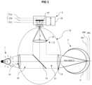
- the ophthalmic imaging systemcomprises a light source 1 adapted to emit an illumination light beam and an imager 2 configured to acquire an image of a light beam returned by a part to be imaged of an eye 3 illuminated by the illumination light beam. Between the light source 1, the imager 2 and the part to be imaged of the eye 3 there is an optical path in which the light beams propagate between the light source 1, the imager 2 and the part to be imaged of the eye 3.
- the optical system 14can thus be broken down into a common part 15 extending to the interface 11 facing the eye 3, a first branch 16 connecting the light source 1 to the common part 15, and a second branch 17 connecting the imager 2 to the common part 15.
- a beam splitter S1is arranged in the optical path to separate the first branch 16 and/or the second branch 17 relative to the common part 15 of the light path.
- a beam splitterallows part of an incident light ray to pass through while reflecting another part in another direction, and can be of any type, such as for example a semi-reflecting mirror.
- a single separator S1is arranged, so that the light beam returned by the eye 3 traveling along the common part 15 of the optical path is deflected towards the second branch 17 intended for the imager 2. It is of course possible to provide more branches, and more separators S1, depending on the number of elements of the system which must use the optical path 14.
- the light source 1is configured to illuminate the retina of the eye 3 so that the imager 2 can acquire an image of the retina of the eye 3.
- the light source 1can emit in any wavelength capable of being used to highlight characteristics of the eye 3.
- the light sourcepreferably emits light at one or more wavelengths only between 800 nm and 900 nm.
- the present methoddoes not rely on the exploitation of light interference.
- the light source 1therefore does not need to be coherent, and can be incoherent.
- the imager 2comprises an optic and an image sensor 19 which can be of any type capable of imaging the retina of the eye 3, and for example be a CCD sensor.
- the imager 2is capable of acquiring images at a frequency greater than 100 Hz, and preferably at a frequency greater than or equal to 150 Hz.
- the imager 2can be configured to make full-field acquisitions, i.e. acquiring at each shot the entire transverse image envisaged for the image focal plane (for example of dimension 4° by 4° on the retinal surface).
- the imager 2can be in a so-called confocal configuration, with a screen pierced with a hole in the focal plane of the imager.
- a scanneris used to transversely scan the position of the image of the confocal hole.
- this configurationallows for increased contrast and improved signal-to-noise ratio, it has the disadvantage of being more complex to implement. work, and above all to significantly reduce the acquisition speed, which can thus cause distortions between parts of images or between images due to eye movements.
- the optical properties of the optical pathdefine an object focal plane 20 in the eye 3 and an image focal plane 21 at the imager 2, the image focal plane 21 being the conjugate plane of the object focal plane 20.
- the object focal plane 20designates the area of the eye 3 from which the photons will be focused at the image focal plane 21 of the imager 2, and will consequently produce a sharp image.
- the positions of the object focal plane 20 and the image focal plane 21depend on the optical characteristics of the optical path, i.e. the optical characteristics of its various components, as well as their spatial arrangement.
- the optical characteristics of the part of the eye 3 crossed by the light beamsare not known in detail, and are variable over time. Indeed, in addition to eye movements, an eye 3 permanently exhibits micro-accommodations of the lens by modification of its vergence, and various other dynamic variations, which prevents knowing a priori the exact position of the image focal plane.
- the human retinais a complex volume composed of hypo-reflective and hyper-reflective layers.
- a lateral movement of the eye 3can thus induce a displacement of the image focal plane, in particular to the extent that three particularly reflective elements are arranged in different layers of the retina: the photoreceptors, the blood vessels and the nerve fibers.
- optical characteristics of the part of the eye 3 crossed by the light beamscannot be controlled, it is possible on the other hand to modify the optical characteristics of the optical system 14 in order to move the object focal plane 20 along the object axis Z. More precisely, a modification of the second branch 17 of the optical system 14 makes it possible to move the image focal plane 21 and its conjugate the object focal plane 20.
- the second branch 17 of the optical system 14is configured to be modified in order to move the object focal plane 20 along the object axis Z.
- the modification of the second branch 17 of the optical system 14can be carried out by a modification of a distance L in this second branch 2 between the sensor 19 of the imager 2 and the output 12 which faces the imager, for example constituted by a lens or any other optical component.
- This modification of the distance Lcan in particular be obtained by a translation of the imager 2.
- the imager 2can be movable in controlled translation in the direction of propagation of the light that the imager 2 receives from the optical system 14.
- the imager 2can be mounted on a motorized plate which allows, depending on commands received, to move the imager 2 in translation using a motor 23. It is also possible for the modification of the second branch 17 of the optical system 14 to be carried out by a modification of an optical element present in this second branch 17. It is for example possible to vary the surface of a deformable mirror, or to modify the shape of a liquid lens, for example constituting the output 12 of the optical system 14.
- the patient's pupilBefore implementing the method, it is preferable to dilate the patient's pupil and paralyze its accommodation. For example, it is possible to use a drop of tropicamide and a drop of 10% phenylphrine for this purpose.
- the width of the pupil obtainedis preferably greater than 5 mm.
- a dilated pupilmakes it possible to obtain a larger ocular numerical aperture, allowing the incident light to be better collimated and focused better on the retina.
- the lateral resolution (perpendicular to the direction of propagation of the beam, in x, y) of the incident light on the retinais proportional (for a perfect eye with circular aperture) to the inverse of the ocular numerical aperture, while the depth extension is proportional to the square of the inverse of the ocular numerical aperture.
- the high ocular numerical aperturelimits the deformation (and in particular the broadening) of the illumination light beam at the focal spot on the retina, and therefore better confines the illumination.
- the imaging systemis less impacted by the diffraction of the light beams.
- the paralysis of accommodationlimits the effects of the dynamics of focusing (defocus) on the temporal evolution of the axial resolution.
- the methodbegins by illuminating the retina with an illuminating light beam emitted by the light source 1.
- the light source 1emits the illuminating light beam which passes through the entrance 10, propagates through the first branch 16, passes through the separator S1, propagates through the common part 15 of the optical system 14, passes through the interface 11, and then reaches the eye 3.
- the illuminating light beampasses through the pupil, the vitreous body, and reaches the retina 6.
- the lightencounters the different tissues constituting the retina 6, organized into retinal layers at different depths.
- the methodtherefore provides for the acquisition by the imager 2 of a series of images of an area to be imaged of the eye 3, the images corresponding to a plurality of different object focal planes 20 distributed along the object axis Z.
- the series of imagescomprises at least 20 images, and preferably at least 50 images, and more preferably at least 100 images.
- the illumination of the area to be imaged of the eye 3 by the illumination light beammay be maintained throughout the acquisition period, or may be intermittent and synchronized with each shot during the acquisition.
- the ophthalmic imaging systemis modified so that the object focal plane 20 is moved along the object axis z.
- the acquisitioncomprises a modification of the second branch 17 of the optical system 14 between each acquired image, preferably without modification of the first branch 16 or of the common part 15.
- the modification of the second branch 17 of the optical system 14 between each acquired imagemay for example comprise a translation of the imager 2, and/or a modification of an optical element present in the second branch 17 of the optical system 14.
- the distribution of the object focal planes 20extends in the area to be imaged of the eye 3 along the object axis Z over a distance greater than minus 50 ⁇ m, and preferably greater than 100 ⁇ m. It is even possible for this distance to be greater than 300 ⁇ m, in order to cover the entire typical thickness of the retina.
- two adjacent object focal planes corresponding to two successive imagesare less than 20 ⁇ m, and preferably less than 10 ⁇ m, and more preferably less than 5 ⁇ m along the object Z axis.
- the movement of the object focal plane 20can be carried out continuously, for example by the continuous translation of the imager 2, and preferably at a constant speed. This allows increased speed and avoids possible jerks. However, it is then necessary to reduce the exposure time for each image in order to avoid the presence of movement-related artifacts, which induces a less favorable signal-to-noise ratio. It is also possible to operate the movement of the imager 2 step by step. This avoids the optical defects resulting from the movement of the imager 2 during the exposure, to the detriment however of the acquisition speed. It is also possible to increase the exposure time for each image in order to improve the signal-to-noise ratio.
- the translation speed of the object focal plane 20is for example between 50 and 200 ⁇ m/s, such as for example 100 ⁇ m/s in the object axis Z.
- the imager 2acquires images with a frequency between 50 Hz and 400 Hz, and preferably between 100 Hz and 300 Hz.
- the exposure time of the sensor 19 for each imageis a compromise between a time that is long enough to obtain a satisfactory signal-to-noise ratio on the acquired image, but not too long so as not to be affected by motion blur resulting from movements of the eye 3 during the exposure time of the sensor 19.
- the exposure time of the sensor 19is preferably less than 10 ms.
- the acquisition of the series of imagesis preferably carried out in less than 5 seconds, and more preferably in less than 3 seconds.
- the relationship between the displacement of the imager 2 and the corresponding displacement of the object focal plane in the area to be imaged of the eye 3depends on the characteristics of the ophthalmic imaging system.
- the relationshipcan for example be a quadratic relationship.
- the optical magnification of the ophthalmic imaging systemmust also be taken into account. For example, with a magnification by a factor of 100, a displacement of the object focal plane of 1 ⁇ m along the object axis Z requires a displacement of 100 ⁇ m of the imager 2.
- a large magnificationis therefore advantageous, since it is easier to control a displacement of 100 ⁇ m of the imager 2 than to control a displacement of 1 ⁇ m of the imager 2.
- Each acquired imageis associated with a value representative of a variation parameter of the second branch 17 of the optical system 14 corresponding to the value taken by this parameter during the acquisition of said image.
- each imagemay correspond to a position of the imager 2 along the image axis at the time when this image is acquired. This position is then associated with said image, possibly in a transformed form.
- the systemcomprises a sensor configured to determine a value representative of a variation parameter of the second branch 17 of the optical system 14, the system being configured to synchronize the acquisition of an image with the measurement of the value of the variation parameter.
- a position sensoris controlled to acquire a measurement of the position of the stage supporting the imager 2 at each image acquisition.
- the imaging systemis configured so that a first object focal plane 2a is located at the back of the retina 6 of the eye 3.
- the imager 2, whose sensor 19 is located at the image focal plane 21aacquires an image.
- the imager 2is moved along the image axis to reduce the distance L between the sensor 19 and the output 12.
- the image focal plane 21bis therefore moved, as is its conjugate the object focal plane 20b.
- the object focal plane 20bis now located less deep in the retina 6.
- the imager 2acquires another image. Then the imager 2 is moved along the image axis to further reduce the distance L between the sensor 19 and the output 12. The image focal plane 21c is therefore moved, as is its conjugate the object focal plane 20c. The object focal plane 20c is now located on the surface of the retina 6, and the imager 2 acquires an image. It should be noted that depending on the configuration of the ophthalmic imaging system, contrary to what is described above, a shortening of the distance L between the output 12 and the sensor 19 (and therefore a moving closer to the image focal plane 21) can cause the object focal plane 20 to move away along the object axis Z relative to the interface 11.
- the acquired imagesnormally more numerous than the three of the simplified example above, form a series of acquired images, spatially ordered by the respective positions of the object focal plane 20 during their acquisitions.
- the order of the images of the image seriescorresponds to the order of the positions of the object focal plane 20 along of the object Z axis.
- the content of the images in the image seriestherefore reflects the three-dimensional structure of the imaged area of the eye 3.
- the modification of the second branch 17consists of moving the imager 2 by a distance d between the acquisition of two images, and there is a ratio of 1 to 10 on the displacement of the object focal plane 21 on the object axis Z, the two successive images will represent imaged planes of the area to be imaged distant by d / 10, and their axial coordinates will be distant from d / 10.
- the exact positions of the object focal planes 20a, 20b, 20c along the object axis Zdo not have to be known exactly before image acquisition. Indeed, since the different object focal planes 20a, 20b, 20c are distributed along the object axis Z, it is possible to determine the imaged depths a posteriori. Thus, the object focal plane 20b may correspond to the bottom of the retina 6, the object focal plane 20a being for example too deep.
- the pixel values of one image in the image seriesmay then be modified by the pixel values of another image in the image series, in order to improve the signal-to-noise ratio, said image and said other image being successive images in the image series.
- the imagesmay result from the sliding average of the images. It would be possible to keep the same number of acquired images, by modifying the values of each image with the images preceding or following it in the series. Preferably, however, successive images are combined with each other, so as to reduce the number of images in the image series.
- the image obtainedmay correspond to the average of the combined images, or more precisely the values of the pixels of the image obtained may result from the average of the values of the corresponding pixels of the combined images.
- This averagemay possibly be weighted, for example with a stronger weight for the central images of the set of combined images.
- each acquired imageis associated with a value representative of a variation parameter of the second branch 17, it is easy to keep such a value associated with each combined image.
- the representative value of the variation parameter associated with a central imageis kept for the combined image.
- the representative value of the variation parameter of the image resulting from the combinationcan also correspond to the average of the representative values of the variation parameter associated with each of the images which have been combined.
- Each of the acquired imagesresult from the collection of photons during the exposure of the imager 2 at the time of the image capture.
- the light coming from the position of the object focal plane 20 at the time of image acquisitionshould reach the imager, generating a sharp image of the imaged area where the object focal plane 21 is located.
- the photons that are backscattered from the out-of-focus planesalso reach the imager.
- FIG. 2shows a view of layers of the retina 6, the vertical direction corresponding to the depth axis of the retina 6 and therefore to the object axis z.
- the first zone 51 delimited by white dashescorresponds to the imaged area included in the depth of field of the object focal plane 20.
- the second zone 52is beyond the object focal plane 20, while the third zone 53 is below the object focal plane 20.
- the two white lines 54, 55delimit the origins of the photons collected by the imager 2 in this configuration.
- the photons originating from the first zone 51come from very close locations, and therefore form clear characteristics on the acquired image.
- This first zone 51therefore produces low, medium and high spatial frequency components, which depend on the structure of the retina in this first zone 51.
- the photons originating from the second zone 52 and the third zone 53are out of focus, and come from various locations in these zones. They cannot therefore form clear characteristics.
- the second zone 52 and the third zone 53therefore produce only low and medium spatial frequency components. Only photons coming from the vicinity of the image focal plane can generate high spatial frequencies.
- Each acquired imagecorresponds to the superposition of several planes located at different depths along the object axis Z.
- At the level of the object focal plane 20corresponds a first plane 51' formed by the photons coming from the first zone 51, on which the characteristics are clear.
- the imagehowever includes other planes 52', 53' corresponding to the zones 52, 53 out of focus, for which the characteristics are blurred.
- the imagereflects an area to be imaged wider than its depth of field, in a blurred manner however.
- the imagethen becomes restricted to the photons originating from the first zone 51 corresponding to the position of the object focal plane 20.
- optical sectioningdesignating the capacity of the imaging system to reject photons coming from out-of-focus planes.
- high-pass filteringis applied in spatial frequencies to each of the images in the image series to obtain a series of filtered images.
- the high-pass filteringaims to remove the low and medium spatial frequency components in the acquired images, i.e. to filter out the out-of-focus photons collected by the imager 2.
- the cut-off frequency of this high-pass filteris chosen to be greater than the average size of the structures of interest in the retina (blood vessels for example), which have a size of less than 50 ⁇ m. With a standardized Butterworth filter of order 2, this corresponds to a spatial cut-off frequency of between 0.04 and 0.1, and preferably between 0.06 and 0.09.
- a low-pass filterin spatial frequencies to remove very high spatial frequencies, typically higher than the spatial frequency of the photoreceptors of the sensor 19, which only appear as noise in the images.
- a cut-off frequency greater than 1can be chosen for a normalized Butterworth filter of order 2, or even greater than 0.8 for a normalized Butterworth filter of order 2 if the signal-to-noise ratio is not satisfactory.
- the high-pass filter and the low-pass filtercan be combined into a band-pass filter.
- the eye 3When acquiring the series of images, it is possible for the eye 3 to move between two shots, generating between successive images a shift transverse to the object axis Z. It is therefore possible to implement a registration of the images, that is to say a translation and/or a rotation of one image relative to another.
- the registration parameterscan be determined by means of a tracking of the movement of the area to be imaged (typically the retina), for example with a dedicated imager acquiring a video whose analysis would determine the movements to be compensated, and therefore the parameters. It is also possible to carry out a registration by means of an algorithm implementing a correlation between successive filtered images.
- the Figure 4a and the Figure 5ashow examples of images acquired from a 900-frame image series.
- the Figure 4ashows image number 200 of the image series, and the Figure 5a shows image number 600.
- the images in the image seriesare combined 10 frames at a time, resulting in a series of 90 combined images replacing the 900 acquired images. More precisely, the pixel values of a combined image result from the average of 10 successive acquired images from the image series. Then a band-pass filtering is applied.
- FIG. 4bshows image 20 of the series of images corresponding to image number 200 illustrated by the Figure 4a
- the Figure 5bshows image number 60 of the series of 90 combined images corresponding to image 600 illustrated by the Figure 5b .
- the filteringremoved the influences of the out-of-focus planes that caused blur.
- the acquired imagesrepresented a superposition of planes along the object Z axis
- the final imagesnow only represent the imaged area of the eye at the object focal plane.
- the applied treatmentstherefore allow spatial discrimination along the object Z axis.
- the presence of retinal cellsis now highlighted, whereas these cells were not visible in the acquired images such as those of Figures 4a And 5a .
- the filteringdoes not modify the association of each image with values representative of a variation parameter of the second branch 17, and therefore of the axial coordinates representative of the distribution of the object focal planes along the object axis Z.
- At least one value of a metric representative of the energy of a region of interest of each filtered imageis determined.
- metricscan be used as a metric representative of the energy. For example, it is possible to determine a spatial frequency energy.
- Values of the metric representative of the energy of different filtered images thus determinedare then combined to obtain a tomographic representation. If several metrics are used, this is a combination of metric values representative of the energy. As each filtered image is associated with values representative of a variation parameter of the second branch corresponding to axial coordinates representative of the distribution of the object focal planes along the axis, the values of the metric representative of the energy of these filtered images are also. Obtaining the tomographic representation therefore consists in spatially organizing these metric values according to their values representative of a variation parameter of the second branch 17 corresponding to axial coordinates. For example, if the variation parameter is a position of the imager 2, the metric values are organized according to the positions of the imager 2 at the time of acquisition of the acquired images.
- the tomographic representationcan simply be the three-dimensional set formed by the juxtaposition along the object axis Z of the filtered images. It is preferable, however, to have a two-dimensional tomographic representation that can take into account in one or two dimensions the three-dimensional structure of the imaged area.
- the methodmay comprise a step in which an axial coordinate of a local maximum of the energy metric is determined from the tomographic representation, and therefore a value representative of a variation parameter, and the second branch 17 is then adjusted as a function of this value representative of the variation parameter so that the image focal plane 21 has a position corresponding to an axial coordinate of the local maximum of the energy metric, and at least one image is acquired.
- the imaging systemwas set up by moving the imager 2 so that the object focal plane 20 was at the coordinate 190 ⁇ m on the object Z axis, and ten images were acquired successively. These images were combined by calculating the average of the values of each pixel.
- the figure 7shows the result of this acquisition. A sharp and precisely localized image of the retinal nerve fiber layer is directly obtained (the white graphic scale at the bottom left is 50 ⁇ m).
- the imaging systemwas configured by moving the imager 2 so that the object focal plane 20 was at the 30 ⁇ m coordinate on the object Z axis, and ten images were acquired successively. These images were combined by calculating the average of the values of each pixel.
- the figure 8shows the result of this acquisition. We directly obtain a clear and precisely localized image of the photoreceptor layer (the white graphic scale at the bottom left is 50 ⁇ m).
- Tomographic imagingcan thus be used to detect layers with a high spatial frequency content, in other words to determine the object focal planes for which sharp images with significant characteristics can be generated.
- This aspectis all the more interesting for imaging or treating patients with retinal diseases. While for a healthy subject, the reflective layers of the retina are easy to localize, this is not the case with a retinal disease, where the retinal anatomy can completely change.
- each imageis associated with a value representative of a variation parameter of the second branch 17 of the corresponding optical system 14. to the value taken by this parameter during the acquisition of said image.
- These parameter values associated with the acquired imagesare preserved during the process, for example during the application of high-pass filtering, the determination of the metric representing the energy, or even during the combination of images with each other.
- the identification and localization of a characteristic element on the tomographic representationmakes it possible to determine the axial coordinate of this element in the tomographic representation, and therefore to identify the representative value of a variation parameter corresponding to the image where this characteristic is located.
- This variation parameterthus determined can be used to control the imaging system or a laser to precisely target an area of the eye 3. In the case of using the imager 2, it is therefore sufficient to reproduce the variation of the second branch 17. In the case of using a laser, it is sufficient to apply a similar variation on the optical path of the laser beam. For example, if the variation parameter associated with the images is a position of the imager 2, it is sufficient to match it with a corresponding position of the laser, for example by means of a mathematical relationship linking a value of the variation parameter to a laser command.
- the tomographic representationcan also be a B-type representation.
- Such a representationtypically maps a representative energy metric value to each axial coordinate and to each coordinate in a direction perpendicular to the object Z axis.
- Such a type B representationmay be constructed in particular by determining a metric value representative of the energy for each of a plurality of areas of interest of each filtered image.
- Each area of interesthas a first dimension in a first direction X perpendicular to the object axis Z, and a second dimension in a second direction Y perpendicular to the object axis Z and to the first direction X.
- the first dimensionis smaller than the second dimension, preferably by a factor of 10.
- the second dimensioncovers the majority of the dimension of the filtered image in the second direction Y, and preferably covers the entire dimension of the filtered image in the second direction Y, typically its entire height.
- the first dimensionmay be reduced to one pixel, or may extend over several pixels, preferably however over a number of pixels less than 10.
- the areas of interest of the filtered imagemay be distinct, but preferably overlap in the first direction X, for example with an offset between them in the first direction X less than their widths.
- FIG. 9A simplified example is illustrated by the figure 9 , in which three successive filtered images 71, 72, 73 are represented in the direction of the object axis Z.
- Each filtered image 71, 72, 73extends over a plane in the first direction X and the second direction Y, which form with the direction of the object axis Z an orthogonal reference frame.
- a first sub-zone 71a, 72a, 73ais defined, which extends over the entire height of the filtered image in the second direction Y, for example over 80 pixels, but over a small width in the first direction X, for example 4 pixels.
- a metric value representative of the energyis calculated for each first sub-zone 71a, 72a, 73a, for example the spatial frequency energy as in the illustrated case, or the spatial variance.
- the positions of sub-areas 71a, 72a, 73a on the different filtered imagesremain identical, corresponding to the same pixels.
- a second sub-area 71b, 72b, 73b of the same size as the first sub-area 71a, 72a, 73ais defined, offset on each filtered image 71, 72, 73 in the first X-direction relative to the first sub-area 71a, 72a, 73a.
- the second sub-area 71b, 72b, 73bis shown in FIG. figure 9 as not covering the first sub-area 71a, 72a, 73a.
- the second sub-area 71b, 72b, 73bis offset in the first X direction by a distance less than the width of the first sub-area 71a, 72a, 73a, and therefore covers the latter.
- the offsetmay be only one pixel between two sub-areas.
- a metric value representative of the energyis calculated for each second sub-area 71b, 72b, 73b. Then the same applies for third sub-areas 71c, 72c, 73c offset relative to the second sub-areas 71b, 72b, 73b.
- the tomographic representation according to the inventionachieves a very satisfactory result, without requiring the implementation of complex interference measurements.
- the depth (along Z) in the retina of each layeris known, as well as the corresponding imaging system controls, as shown above.
- the size of the subareasinfluences the contrast and resolution of the tomographic representation.
- the larger the size of the subareasthe less details will be preserved (such as longitudinal blood vessels and photoreceptors), and the layers will be smoother, as in the case of the OCT image of the figure 12 .
- the tomographic representationis noisier, but the finer details are preserved, allowing better visualization of structures such as blood vessels or photoreceptors.
- the system illustrated by the figure 1is a simplified diagram of an exemplary imaging system according to a possible embodiment of the invention.
- the optical system 14typically comprises numerous optical elements.
- the optical system 14may comprise elements of an adaptive optics loop and elements for moving light beams.
- the imaging systemmay comprise a treatment laser.
- figure 13thus presents a more detailed example of an imaging system, by way of non-limiting example, the different elements constituting it being able to be combined or taken in isolation in an imaging system.
- This second light source 1'is used to detect these alterations of the wave front.
- a real human eye 3is not strictly stigmatic, that is to say that the image of a point is not a rigorously sharp point.
- the propagation of light in the eye 3highlights ocular aberrations which give rise to defects in this light, and in particular with regard to its wavefront.
- These ocular aberrationscan be static, the most common examples being vision defects corrected by glasses (myopia, hyperopia, astigmatism, etc.).
- Aberrationscan also be dynamic, for example caused by micro-accommodations of the lens, the flow of the tear film, and eye movements. These aberrations result in a point spread function ("Point Spread Function" or PSF in English) which deviates from that of a theoretical perfect eye, and which varies rapidly over time.
- PSFPoint Spread Function
- the second light sourcehas wavelengths between 600 nm and 700 nm, in particular because this range highlights the main aberrations, and is preferably still monochromatic.
- a first actuatormakes it possible to control the movement of the light beam in the optical path relative to the retina of the eye 3.
- the first actuatorcomprises a scanner SC1 formed by two pivoting mirrors, and makes it possible to scan the entire central zone of the retina.
- the lightthen passes through an interface 11 facing the eye 3 through which the illuminating light beam exits to reach the eye 3.
- the illuminating light beampasses through the pupil, the vitreous body, and reaches the retina 6.
- the lightencounters the different tissues constituting the retina 6, organized into retinal layers at different depths.
- the lightis backscattered by these tissues and exits the eye, constituting an image light beam originating from the eye which enters the optical system 14 via the interface 11.
- the image light beampasses back through the scanner SC1, then crosses the separator S1, and reaches a corrective element 30 of the adaptive optics, used to correct the wavefront of the light beams passing through the eye 3, both the image light beam and the laser beam, in order to compensate for the deformations undergone by the light fluxes in the eye 3.
- the corrective element 30is a deformable mirror whose surface changes to compensate for the measured wavefront deformations.
- the image light fluxthen passes through a separator S3 which derives from the optical path an image of the retina to one or more imagers, upstream of the corrective element 30 of the adaptive optics. Another part of the image light flux continues towards a separator S4 which deflects the light flux towards a wave surface analyzer 31 or wave front analyzer, configured to receive light from the optical path.
- the lightis derived by means of the separator S4 placed on the optical path.
- the wave surface analyzer 31determines a measurement representative of a shape of a wave surface of the light passing along the optical path. More precisely, the wave surface analyzer 31 decomposes a wave front into elementary wave fronts and it makes it possible to determine for each elementary wave front its orientation. The measurement of these orientations makes it possible after integration to go back to the shape of the wave front.
- a feedback loop 32makes it possible to use the measurements of the wave surface analyzer 31 to control the correction element 30. More precisely, the measurements of the wave surface analyzer 31 are received and processed by a processing module of the feedback loop 32, preferably a real-time computer, configured to receive the measurement of the wave surface analyzer, and to control the correction element 30 according to the measurement of the wave surface analyzer, in order to compensate for the detected disturbances.
- the processing modulecalculates the commands (for example voltages or intensities) to be sent to the deformable mirror, also placed in a pupil plane. The surface of the deformable mirror then changes to compensate for the measured wavefront deformations.
- the image light flux derived by the separator S3 to the imager 2then passes into a separator S5 which makes it possible to derive a portion of the light flux traveling along the optical path toward the output 12 facing the imager 2, through which the image light beam exits to reach the imager 2, which makes it possible to obtain an image of the area of the retina of the eye 3 facing the interface 11.
- a secondary imager 2'may be provided, supplied with light flux from the separator S5 through a secondary output 12'.
- This secondary imager 2'is a stabilization camera used to implement a regulation to control the position of the interface 11 with respect to the retina to be treated.
- a stabilization loop 33connects the secondary imager 2' to the first actuator. More specifically, the secondary imager 2' transmits acquired images to a processing module of the stabilization loop 33, preferably a real-time computer, which from these images determines a command of the scanner SC1 of the first actuator to move the light beam in the optical path relative to the retina of the eye 3 in order to stabilize the position of the light beam, in particular by compensating for involuntary movements of the eye 3.
- the processing modulecan for example use an image of the photoreceptors and a correlation-type algorithm to determine the movements of the retina, and determine a command of the first actuator so that the light beam follows these movements.
- the systemmay include a photocoagulation laser 35 configured to emit in an emission direction a laser beam into the optical system.
- the photocoagulation laser 35may include a laser source and a transport optical fiber having a core diameter preferably less than 12 ⁇ m, and more preferably less than 8 ⁇ m.
- the laser sourceis preferably a fiber laser source, i.e. one the amplifying medium is created in an optical fiber doped with a rare earth, and can be single-mode.
- the photocoagulation laser 35is configured to emit in a wavelength between 520 nm and 690 nm, preferably between 540 nm and 630 nm.
- the photocoagulation laser 35may be associated with a control member 36 configured to determine the value of the variation parameter corresponding to the position of a target in the tomographic representation derived from the images acquired by the imager 2, and to control the photocoagulation laser 35 by means of a depth command (z) derived from this value of the variation parameter. More precisely, the photocoagulation laser 35 is movable in translation in its emission direction and the depth command is a command to move the photocoagulation laser 35.
- a motor 37may be provided to move the photocoagulation laser 35 in translation in its emission direction. It is this motor which then receives the depth command (z) sent by the control member 36.
- the tomographic representationassociates variation parameter values with each area of the imaged area (such as a position of the imager 2), it is possible to assign a variation parameter value to a laser target identified on the tomographic representation.
- the controller 36can therefore determine the commands to be applied to the photocoagulation laser 35 so that the laser beam reaches this laser target precisely, without damaging adjacent tissue, for example by means of a relationship linking a value of the variation parameter to a laser control value, such as a laser movement or a laser position.
- the control member 36is further configured to determine a movement command (x, y) of the laser beam at least in a plane perpendicular to the direction of propagation of the laser, defined by two distinct directions denoted x and y.
- the second actuatormay comprise, as illustrated in the figure 13 , an SC2 scanner positioned in the optical path and adapted to move the laser beam in a focal plane (x, y) perpendicular to the propagation of the laser beam,
- the SC2 scanneracts for example by modifying the respective orientations of two mirrors facing each other, thus angularly shifting the laser beam which emerges from them.
- the control member 36may be any computer, such as for example a real-time calculator, comprising a processor and a memory, capable of determining commands for the laser beam from information derived from the tomographic representation of the eye 3, possibly supplemented by other information, some of which may correspond to data entered by an operator, such as for example an instruction for the area to be treated.
- a real-time calculatorcomprising a processor and a memory, capable of determining commands for the laser beam from information derived from the tomographic representation of the eye 3, possibly supplemented by other information, some of which may correspond to data entered by an operator, such as for example an instruction for the area to be treated.
- the photocoagulation laser 35After being positioned along its direction by the motor 37 controlled by the depth command (z) sent by the control member 36, the photocoagulation laser 35 emits a laser beam passing through the lens 38, then arrives at the scanner SC2 where it is reoriented in the x and y directions in accordance with the movement commands sent by the control member 36.
- the laser beamthen joins the separator S4, then travels the same optical path (in the opposite direction) as the image light beam, namely it passes through the separator S3, the corrective element 30 of the adaptive optics, the separator S1, and the first actuator (scanner SC1) before passing through the interface 11 to reach the retina of the eye 3.
Landscapes
- Life Sciences & Earth Sciences (AREA)
- Health & Medical Sciences (AREA)
- Medical Informatics (AREA)
- Biophysics (AREA)
- Ophthalmology & Optometry (AREA)
- Engineering & Computer Science (AREA)
- Biomedical Technology (AREA)
- Heart & Thoracic Surgery (AREA)
- Physics & Mathematics (AREA)
- Molecular Biology (AREA)
- Surgery (AREA)
- Animal Behavior & Ethology (AREA)
- General Health & Medical Sciences (AREA)
- Public Health (AREA)
- Veterinary Medicine (AREA)
- Eye Examination Apparatus (AREA)
Description
Translated fromFrenchLa présente invention appartient au domaine de l'ophtalmologie. Plus précisément, l'invention concerne un procédé de tomographie en incohérence optique permettant une imagerie in vivo temps réel de la rétine, un système d'imagerie ophtalmique, et un système de photocoagulation laser d'une rétine.The present invention belongs to the field of ophthalmology. More specifically, the invention relates to an optical incoherence tomography method allowing real-time in vivo imaging of the retina, an ophthalmic imaging system, and a laser photocoagulation system of a retina.
L'oedème maculaire est une affection rétinienne assez fréquente se caractérisant par un d'un oedème de la région centrale de la rétine (macula) lié à des anomalies des petits vaisseaux sanguins, entraînant une baisse de l'acuité visuelle. L'oedème maculaire est la principale manifestation de la rétinopathie diabétique, qui est la cause principale de cécité avant 55 ans. Le traitement standard de ces oedèmes maculaires consiste à réaliser une photocoagulation de ces vaisseaux dans la zone centrale de la rétine à l'aide d'un laser. D'autres maladies peuvent également bénéficier de la photocoagulation de la macula, comme les occlusions veineuses rétiniennes.Macular edema is a fairly common retinal condition characterized by edema of the central region of the retina (macula) related to abnormalities of the small blood vessels, leading to a decrease in visual acuity. Macular edema is the main manifestation of diabetic retinopathy, which is the leading cause of blindness before the age of 55. The standard treatment for these macular edemas consists of photocoagulation of these vessels in the central area of the retina using a laser. Other diseases can also benefit from photocoagulation of the macula, such as retinal vein occlusions.
Lors d'une photocoagulation, la cible thérapeutique du laser peut se situer au niveau de deux couches :
- la couche des vaisseaux sanguins rétiniens, dans le cas d'un oedème localisé. Dans ce cas, l'oedème est causé par une dilatation vasculaire appelée macroanévrysme sur un vaisseau rétinien identifié, et l'on procède à une photocoagulation directe du vaisseau impliqué ;
- l'épithélium pigmentaire rétinien, dans le cas d'un oedème diffus. Une solution consiste alors à stimuler la fonction d'absorption de l'épithélium pigmentaire, en le photocoagulant avec des impacts répétés.
- the layer of retinal blood vessels, in the case of localized edema. In this case, the edema is caused by a vascular dilation called a macroaneurysm on an identified retinal vessel, and direct photocoagulation of the involved vessel is performed;
- the retinal pigment epithelium, in the case of diffuse edema. One solution then consists of stimulating the absorption function of the pigment epithelium, by photocoagulating it with repeated impacts.
Ces deux couches de la rétine sont séparées d'une centaine de microns, et sont entourés d'autres couches correspondant à des tissus fonctionnels qu'il faut s'efforcer de préserver, sous peine de provoquer une baisse de vision définitive.These two layers of the retina are separated by about a hundred microns, and are surrounded by other layers corresponding to functional tissues that must be preserved, otherwise a permanent loss of vision will result.
Jusqu'à présent, le chirurgien opérant le laser ne disposait que d'une visualisation bidimensionnelle de la rétine à la lampe à fente, vue de face, sur laquelle le chirurgien s'appuie pour localiser le point d'impact laser en surface de la rétine, et doser la puissance du laser : il est recommandé d'appliquer le laser jusqu'à observer un discret blanchiment à la lampe à fente. Il apparaît donc que dans les procédures chirurgicales actuelles, la focalisation et le dosage du laser sont très empiriques. De fait, les procédures de traitement standard sont assez peu reproductibles d'un praticien à l'autre.Until now, the surgeon operating the laser only had a two-dimensional visualization of the retina at the slit lamp, seen from the front, on which the surgeon relies to locate the laser impact point on the surface of the retina, and to dose the laser power: it is recommended to apply the laser until a slight whitening is observed at the slit lamp. It therefore appears that in current surgical procedures, the focusing and dosage of the laser are very empirical. In fact, standard treatment procedures are not very reproducible from one practitioner to another.
En outre, pendant l'opération, l'oeil est plus ou moins stabilisé avec un verre de contact maintenu sur l'oeil, qui ne filtre que très partiellement les continuels mouvements involontaires de fixation de l'oeil. Il en résulte que l'impact laser peut ne pas correspondre à la position visée sur l'image de fond d'oeil obtenue par la lampe à fente.Furthermore, during the operation, the eye is more or less stabilized with a contact lens held on the eye, which only very partially filters the continuous involuntary fixation movements of the eye. As a result, the laser impact may not correspond to the position targeted on the fundus image obtained by the slit lamp.
Pour pallier ce manque de précision dans la localisation de l'impact laser, les systèmes actuels sont configurés pour générer un impact laser de grande taille, afin de s'assurer que la photocoagulation recouvre entièrement la zone à traiter. La grande taille de l'impact laser est obtenue par la délivrance d'un faisceau laser large, avec un diamètre latéral de la tache focale sur la rétine allant de 100 µm à 500 µm, et présentant une faible ouverture optique, avec une extension longitudinale (en profondeur) de la tache focale sur la rétine d'environ 300 µm.To overcome this lack of precision in the localization of the laser impact, current systems are configured to generate a large laser impact, in order to ensure that the photocoagulation completely covers the area to be treated. The large laser impact size is achieved by delivering a wide laser beam, with a lateral diameter of the focal spot on the retina ranging from 100 µm to 500 µm, and having a small optical aperture, with a longitudinal extension (in depth) of the focal spot on the retina of approximately 300 µm.
Par ailleurs, un impact laser de grande taille permet également de pallier différentes aberrations oculaires réduisant la précision de la localisation de l'impact laser. En effet, un oeil humain réel n'est pas strictement stigmatique, c'est-à-dire que l'image d'un point n'est pas un point rigoureusement net. Ces aberrations oculaires peuvent être statiques, les exemples les plus courants étant les défauts de vision corrigés par les lunettes (myopie, hypermétropie, astigmatisme, etc.). Les aberrations peuvent également être dynamiques, par exemple causées par des micro-accommodations du cristallin, l'écoulement du film lacrymal, et les mouvements oculaires. Ces aberrations se traduisent par une fonction d'étalement du point ("Point Spread Function" ou PSF en anglais) qui s'éloigne de celle d'un oeil parfait théorique, et qui varie rapidement dans le temps.Furthermore, a large laser impact also makes it possible to overcome various ocular aberrations that reduce the accuracy of the laser impact localization. Indeed, a real human eye is not strictly stigmatic, i.e. the image of a point is not a rigorously sharp point. These ocular aberrations can be static, the most common examples being vision defects corrected by glasses (myopia, hyperopia, astigmatism, etc.). Aberrations can also be dynamic, for example caused by micro-accommodations of the lens, the flow of the tear film, and eye movements. These aberrations result in a point spread function (PSF) that deviates from that of a theoretical perfect eye, and which varies rapidly over time.
La grande taille des impacts laser actuels n'est pas adaptée à la taille des zones à traiter. A titre d'exemple, les macro-anévrysmes présentent des tailles variant typiquement entre 100 µm et 300 µm, alors même que l'impact laser présente un diamètre d'environ 300 µm, sans compter la diffusion thermique se produisant autour de la zone d'impact laser. Il en résulte qu'apparaissent des lésions des tissus sains avoisinants la zone à traiter. Or, la couche des vaisseaux sanguins rétiniens et l'épithélium pigmentaire rétinien sont entourés de tissus fonctionnels dont l'altération peut entraîner une baisse de vision définitive.The large size of current laser impacts is not adapted to the size of the areas to be treated. For example, macroaneurysms typically have sizes varying between 100 µm and 300 µm, even though the laser impact has a diameter of approximately 300 µm, not counting the thermal diffusion occurring around the laser impact zone. As a result, lesions appear in the healthy tissues surrounding the area to be treated. However, the The retinal blood vessel layer and the retinal pigment epithelium are surrounded by functional tissues, the alteration of which can lead to permanent vision loss.
Il est donc nécessaire de disposer d'un moyen d'imagerie efficace, offrant une grande précision et une grande réactivité afin de pouvoir rendre compte des mouvements de l'oeil.It is therefore necessary to have an efficient means of imaging, offering great precision and great responsiveness in order to be able to account for eye movements.
Les ophtalmoscope peuvent être classés en deux catégories :
- l'ophtalmoscope à champ plein (ou FIO pour "flood-illumination ophtalmoscope" en anglais), où la rétine est illuminée en champ plein, et un imageur acquiert une image de la lumière réfléchie qui ressort de l'oeil;
- l'ophtalmoscope à balayage laser (ou SLO pour l'anglais "scanning laser ophtalmoscope"), où la rétine est illuminée par une source ponctuelle et un imageur acquiert une image de la lumière réfléchie qui ressort de l'oeil, l'image étant acquise au cours du balayage laser de la surface à imager.
- the flood-illumination ophthalmoscope (or FIO), where the retina is illuminated in a full field, and an imager acquires an image of the reflected light coming out of the eye;
- the scanning laser ophthalmoscope (or SLO), where the retina is illuminated by a point source and an imager acquires an image of the reflected light coming out of the eye, the image being acquired during the laser scan of the surface to be imaged.
Le SLO peut bénéficier d'un sectionnement optique en plaçant un écran percé d'un petit trou au plan focal de l'imageur, approche désignée comme confocale. L'écran percé permet de rejeter physiquement les photons en provenance des plans hors foyer.The SLO can benefit from optical sectioning by placing a screen with a small hole in it at the focal plane of the imager, an approach referred to as confocal. The holed screen physically rejects photons from out-of-focus planes.
Chaque type d'ophtalmoscope peut être utilisé suivant deux configurations de détection en fonction des propriétés de la lumière utilisées : en incohérence ou en cohérence. La détection en cohérence se fait principalement selon la technique de tomographie en cohérence optique, ou OCT pour l'anglais "optical cohérence tomography". Cette technique consiste à produire des interférences entre la lumière réfléchie par la rétine et une partie de la lumière d'illumination utilisée comme référence. Grâce aux motifs d'interférence générés, la différence de temps de propagation entre la rétine et le faisceau de référence peut être déterminée, permettant une résolution axiale de quelques micromètres.Each type of ophthalmoscope can be used in two detection configurations depending on the properties of the light used: incoherence or coherence. Coherence detection is mainly done using the optical coherence tomography technique, or OCT. This technique consists of producing interference between the light reflected by the retina and part of the illumination light used as a reference. Thanks to the interference patterns generated, the difference in propagation time between the retina and the reference beam can be determined, allowing an axial resolution of a few micrometers.
Toutefois, dans les systèmes OCT, des perturbations oculaires comme par exemple les mouvements des yeux ou des aberrations optiques, affectent la qualité de l'image rétinienne. Alors que les effets des mouvements des yeux (flou et distorsions) peuvent être minimisés par un post-traitement, les aberrations oculaires sont évitées par l'utilisation d'un système avec une faible ouverture optique, typiquement entre 1 mm et 2 mm. A l'exception de la résolution axiale qui ne dépend pas de l'ouverture optique, cette petite ouverture optique limite la résolution dans les autres directions, et certaines caractéristiques rétiniennes ne sont pas imagées convenablement.However, in OCT systems, ocular disturbances such as eye movements or optical aberrations affect the quality of the retinal image. While the effects of eye movements (blurring and distortions) can be minimized by post-processing, ocular aberrations are avoided by using a system with a small optical aperture, typically between 1 mm and 2 mm. Except for the axial resolution which does not depend on the optical aperture, this small optical aperture limits the resolution in other directions, and some retinal features are not imaged properly.
En particulier, un système OCT est faiblement sensible au défocus (correspondant à un changement d'accommodation de l'oeil), et est fortement sensible aux mouvements axiaux de la rétine (pulsation) et de l'oeil. Comme le positionnement axial d'un laser thérapeutique est donné par un défocus pur, l'OCT se révèle impropre à être utilisée pour déterminer et contrôler le défocus à être appliqué sur le laser thérapeutique afin de bien positionner axialement l'impact laser sur la cible thérapeutique et ainsi éviter d'endommager les tissus rétiniens sains adjacents à la zone d'impact désirée du laser.In particular, an OCT system is weakly sensitive to defocus (corresponding to a change in accommodation of the eye), and is strongly sensitive to axial movements of the retina (pulsation) and the eye. Since the axial positioning of a therapeutic laser is given by a pure defocus, OCT is unsuitable for use in determining and controlling the defocus to be applied to the therapeutic laser in order to properly axially position the laser impact on the therapeutic target and thus avoid damaging healthy retinal tissues adjacent to the desired laser impact zone.
Des systèmes d'imagerie tomographique des différents couches rétinales sont divulgués dans les documents
L'invention a pour but de permettre la construction d'une représentation tomographique dans laquelle chaque caractéristique présente une position axiale connue. A cet effet, il est proposé un procédé d'imagerie ophtalmique d'une partie à imager d'un oeil au moyen d'un système d'imagerie ophtalmique, ledit système d'imagerie ophtalmique comprenant :
- une source lumineuse adaptée pour émettre un faisceau lumineux d'éclairage,
- un imageur adapté pour acquérir une image d'un faisceau lumineux renvoyé,
- un système optique adapté pour la propagation de faisceaux lumineux, le système optique comprenant une partie commune s'étendant jusqu'à une interface face à l'oeil, une première branche reliant la source lumineuse à la partie commune, et une seconde branche reliant l'imageur à la partie commune,
- a) éclairage de la partie à imager de l'oeil par un faisceau lumineux d'éclairage émis par la source lumineuse, et acquisition par l'imageur d'une série d'images de la zone à imager correspondants à une pluralité de plans focaux objet différents distribués le long d'un axe objet, l'acquisition comprenant une modification d'un paramètre de variation de la seconde branche du système optique entre chaque image acquise,
- b) application d'un filtrage passe-haut en fréquences spatiales sur chacune des images de la série d'image pour obtenir une série d'images filtrées,
- c) pour chaque image filtrée, détermination d'au moins une valeur de métrique représentative de l'énergie d'une zone d'intérêt de chaque image filtrée, et
- d) combinaison de valeurs d'une métrique représentative de l'énergie de différentes images filtrées, chacune associée avec des coordonnées axiales représentatives de la distribution des plans focaux objet le long de l'axe objet, pour obtenir une représentation tomographique.
- a light source suitable for emitting a beam of light for illumination,
- an imager adapted to acquire an image of a returned light beam,
- an optical system adapted for the propagation of light beams, the optical system comprising a common part extending to an interface facing the eye, a first branch connecting the light source to the common part, and a second branch connecting the imager to the common part,
- a) illumination of the part of the eye to be imaged by an illuminating light beam emitted by the light source, and acquisition by the imager of a series of images of the area to be imaged corresponding to a plurality of different object focal planes distributed along an object axis, the acquisition comprising a modification of a variation parameter of the second branch of the optical system between each acquired image,
- b) applying high-pass filtering in spatial frequencies to each of the images in the image series to obtain a series of filtered images,
- (c) for each filtered image, determining at least one metric value representative of the energy of an area of interest of each filtered image, and
- d) combination of values of a metric representative of the energy of different filtered images, each associated with axial coordinates representative of the distribution of object focal planes along the object axis, to obtain a tomographic representation.
Le procédé est avantageusement complété par les caractéristiques suivantes, prises seules ou en une quelconque de leur combinaison techniquement possible :
- les coordonnées axiales correspondent à des valeurs représentatives d'un paramètre de variation de la seconde branche des images acquises correspondant aux images filtrées ;
- la modification de la seconde branche du système optique entre chaque image acquise comprend une translation de l'imageur, et/ou une modification d'un élément optique présent dans la seconde branche du système optique ;
- la série d'images de la rétine comprend au moins 20 images acquises sans modification de la première branche et de la partie commune du système optique ;
- l'acquisition de la série d'images est effectuée en moins de 5 secondes;
- la représentation tomographique est une représentation de type A qui fait correspondre une métrique représentative de l'énergie pour une pluralité de coordonnées axiales, ou la représentation tomographique est une représentation de type B qui fait correspondre une métrique représentative de l'énergie pour une pluralité de coordonnées axiales et pour une pluralité de coordonnées dans une direction perpendiculaire à l'axe objet ;
- des images acquises successives sont combinées entre elles pour résulter en une image combinée dont les valeurs de pixels correspondent à une combinaison des valeurs des pixels des images acquises successives ;
- au moins trois images acquises successives sont combinées entre elles, et la combinaison des valeurs des pixels des images acquises successives consiste en une moyenne de ces valeurs des pixels des images acquises successives ;
- la métrique représentative de l'énergie est une énergie de fréquence spatiale, une variance spatiale de l'image, une énergie laplacienne de l'image, ou une fonction de Brenner de l'image ;
- le procédé comprend en outre une étape e) dans laquelle une valeur représentative d'un paramètre de variation de la seconde branche correspondant à un maximum local de la métrique d'énergie est déterminé à partir de la représentation, et la seconde branche est ensuite réglée selon cette valeur représentative du paramètre de variation de sorte que le plan focal image ait une position correspondant à une coordonnée axiale du maximum local de la métrique d'énergie, et au moins une image est acquise.
- the axial coordinates correspond to values representative of a variation parameter of the second branch of the acquired images corresponding to the filtered images;
- the modification of the second branch of the optical system between each acquired image comprises a translation of the imager, and/or a modification of an optical element present in the second branch of the optical system;
- the retinal image series comprises at least 20 images acquired without modification of the first branch and the common part of the optical system;
- the acquisition of the image series is carried out in less than 5 seconds;
- the tomographic representation is a type A representation that maps a representative metric of energy for a plurality of axial coordinates, or the tomographic representation is a type B representation that maps a representative metric of energy for a plurality of axial coordinates and for a plurality of coordinates in a direction perpendicular to the object axis;
- successive acquired images are combined with each other to result in a combined image whose pixel values correspond to a combination of the pixel values of the successive acquired images;
- at least three successive acquired images are combined with each other, and the combination of the pixel values of the successive acquired images consists of an average of these pixel values of the successive acquired images;
- the representative metric of energy is a spatial frequency energy, a spatial variance of the image, a Laplacian energy of the image, or a Brenner function of the image;
- the method further comprises a step e) in which a representative value of a variation parameter of the second branch corresponding to a local maximum of the energy metric is determined from the representation, and the second branch is then adjusted according to this representative value of the variation parameter so that the image focal plane has a position corresponding to an axial coordinate of the local maximum of the energy metric, and at least one image is acquired.
L'invention concerne également un système d'imagerie ophtalmique comprenant :
- une source lumineuse adaptée pour émettre un faisceau lumineux d'éclairage,
- un imageur adapté pour acquérir une image d'un faisceau lumineux renvoyé,
- un système optique adapté pour la propagation de faisceaux lumineux, le système optique comprenant une partie commune s'étendant jusqu'à une interface face à l'oeil, une première branche reliant la source lumineuse à la partie commune, et une seconde branche reliant l'imageur à la partie commune,
- le système d'imagerie ophtalmique étant configuré pour:
- a) éclairer la partie à imager de l'oeil par un faisceau lumineux d'éclairage émis par la source lumineuse, et acquérir par l'imageur une série d'images de la zone à imager correspondants à une pluralité de plans focaux objet différents distribués le long d'un axe objet, l'acquisition comprenant une modification de la seconde branche du système optique entre chaque image acquise,
- b) appliquer un filtrage passe-haut en fréquences spatiales sur chacune des images de la série d'image pour obtenir une série d'images filtrées,
- c) pour chaque image filtrée, déterminer au moins une métrique représentative de l'énergie d'une zone d'intérêt de chaque image filtrée, et
- d) combiner des valeurs d'une métrique représentative de l'énergie de différentes images filtrées, chacune associée avec des coordonnées axiales représentatives de la distribution des plans focaux objet le long de l'axe objet, et obtenir une représentation tomographique,
- le système d'imagerie ophtalmique étant configuré pour mettre en oeuvre le procédé selon l'invention.
- a light source suitable for emitting a beam of light for illumination,
- an imager adapted to acquire an image of a returned light beam,
- an optical system adapted for the propagation of light beams, the optical system comprising a common part extending to an interface facing the eye, a first branch connecting the light source to the common part, and a second branch connecting the imager to the common part,
- the ophthalmic imaging system being configured to:
- a) illuminating the part of the eye to be imaged by an illuminating light beam emitted by the light source, and acquiring by the imager a series of images of the area to be imaged corresponding to a plurality of different object focal planes distributed along an object axis, the acquisition comprising a modification of the second branch of the optical system between each acquired image,
- b) apply high-pass filtering in spatial frequencies on each of the images of the image series to obtain a series of filtered images,
- (c) for each filtered image, determine at least one metric representative of the energy of an area of interest of each filtered image, and
- (d) combining values of a representative energy metric from different filtered images, each associated with axial coordinates representative of the distribution of object focal planes along the object axis, and obtaining a tomographic representation,
- the ophthalmic imaging system being configured to implement the method according to the invention.
De préférence, le système de photocoagulation laser d'une rétine, comprend :
- le système d'imagerie ophtalmique décrit,
- un laser de photocoagulation configuré pour émettre dans une direction d'émission un faisceau laser dans le système optique,
- the described ophthalmic imaging system,
- a photocoagulation laser configured to emit in an emission direction a laser beam into the optical system,
L'invention sera mieux comprise, grâce à la description ci-après, qui se rapporte à des modes de réalisations et des variantes selon la présente invention, donnés à titre d'exemples non limitatifs et expliqués avec référence aux dessins schématiques annexés, dans lesquels :
- la
figure 1 montre schématiquement une vue simplifiée d'un exemple de système d'imagerie selon un mode de réalisation possible de l'invention ; - la
figure 2 montre une vue de couches d'une rétine, avec l'origine des photons recueillis par l'imageur selon un mode de réalisation possible de l'invention ; - la
figure 3 est un schéma illustrant la superposition de plans imagés le long de l'axe objet dans une image acquise selon un mode de réalisation possible de l'invention ; - la
figure 4a est la 200ème image acquise d'un exemple d'une série d'images acquises selon un mode de réalisation possible de l'invention ; - la
figure 4b est la 20ème image filtrée résultant de la combinaison et du filtrage de la série d'images de lafigure 4a selon un mode de réalisation possible de l'invention ; - la
figure 5a est la 600ème image acquise d'un exemple d'une série d'images acquises selon un mode de réalisation possible de l'invention ; - la
figure 5b est la 60ème image filtrée résultant de la combinaison et du filtrage de la série d'images de lafigure 5a selon un mode de réalisation possible de l'invention ; - la
figure 6 est un exemple de représentation tomographique de type A selon un mode de réalisation possible de l'invention ; - la
figure 7 est une image acquise au plan focal objet correspondant à la coordonnée 190 µm sur la représentation tomographique de lafigure 6 ; - la
figure 8 est une image acquise au plan focal objet correspondant à la coordonnée 30 µm sur la représentation tomographique de lafigure 6 ; - la
figure 9 est un schéma illustrant une première étape de construction d'une représentation tomographique de type B selon un mode de réalisation possible de l'invention, - la
figure 10 est un schéma illustrant le résultat de la première étape de construction d'une représentation tomographique de type B selon un mode de réalisation possible de l'invention ; - la
figure 11 est un exemple de représentation tomographique de type B selon un mode de réalisation possible de l'invention ; - la
figure 12 est un exemple d'image OCT de la même zone imagée de la rétine que lafigure 11 ; - la
figure 13 présente ainsi un exemple plus détaillé de système d'imagerie selon un mode de réalisation possible de l'invention.
- there
figure 1 schematically shows a simplified view of an exemplary imaging system according to a possible embodiment of the invention; - there
figure 2 shows a view of layers of a retina, with the origin of the photons collected by the imager according to a possible embodiment of the invention; - there
figure 3 is a diagram illustrating the superposition of imaged planes along the object axis in an image acquired according to a possible embodiment of the invention; - there
Figure 4a is the200th image acquired from an example of a series of images acquired according to a possible embodiment of the invention; - there
Figure 4b is the20th filtered image resulting from the combination and filtering of the series of images from theFigure 4a according to a possible embodiment of the invention; - there
Figure 5a is the600th image acquired from an example of a series of images acquired according to a possible embodiment of the invention; - there
Figure 5b is the60th filtered image resulting from the combination and filtering of the series of images from theFigure 5a according to a possible embodiment of the invention; - there
figure 6 is an example of a type A tomographic representation according to a possible embodiment of the invention; - there
figure 7 is an image acquired at the object focal plane corresponding to the 190 µm coordinate on the tomographic representation of thefigure 6 ; - there
figure 8 is an image acquired at the object focal plane corresponding to the 30 µm coordinate on the tomographic representation of thefigure 6 ; - there
figure 9 is a diagram illustrating a first step in constructing a type B tomographic representation according to a possible embodiment of the invention, - there
figure 10 is a diagram illustrating the result of the first step of constructing a type B tomographic representation according to a possible embodiment of the invention; - there
figure 11 is an example of a type B tomographic representation according to a possible embodiment of the invention; - there
figure 12 is an example of an OCT image of the same imaged area of the retina as thefigure 11 ; - there
figure 13 thus presents a more detailed example of an imaging system according to a possible embodiment of the invention.
En référence à la
Le chemin optique est constitué des différents composant traversés par les faisceaux lumineux. Le chemin optique comprend ainsi une partie de l'oeil 3 que traverse le faisceau lumineux d'éclairage pour atteindre la partie à imager et que traverse le faisceau lumineux renvoyé pour ressortir de l'oeil 3 à partir de la partie à imager. Par exemple, lorsque la partie à imager est une rétine, le chemin optique comprend la cornée, le cristallin et le corps vitré. Le chemin optique comprend également plusieurs éléments optiques permettant de réaliser différentes fonctions lors de la propagation des faisceaux lumineux, tels que des lentilles qui permettent de faire converger ou diverger les faisceaux lumineux les traversant ou des miroirs pour orienter les faisceaux. Ces éléments optiques forment un système optique 14 comprenant :
une entrée 10 face à la source lumineuse 1 par laquelle pénètre le faisceau lumineux d'éclairage émis par la source lumineuse 1,une interface 11 face à l'oeil 3 par laquelle sort le faisceau lumineux d'éclairage pour atteindre l'oeil 3 et par laquelle le faisceau lumineux d'image en provenance de l'oeil entre dans le système optique,une sortie 12 face à l'imageur 2, par laquelle sort le faisceau lumineux d'image pouratteindre l'imageur 2.
- an
entrance 10 facing thelight source 1 through which the illuminating light beam emitted by thelight source 1 enters, - an
interface 11 facing theeye 3 through which the illumination light beam exits to reach theeye 3 and through which the image light beam coming from the eye enters the optical system, - an
output 12 facing theimager 2, through which the image light beam exits to reach theimager 2.
Le système optique 14 peut ainsi être décomposé en une partie commune 15 s'étendant jusqu'à l'interface 11 face à l'oeil 3, une première branche 16 reliant la source lumineuse 1 à la partie commune 15, et une seconde branche 17 reliant l'imageur 2 à la partie commune 15. Typiquement, un séparatrice S1 est disposée dans le chemin optique permet de séparer la première branche 16 et/ou la seconde branche 17 par rapport à la partie commune 15 du chemin lumineux. Dans la description, une séparatrice, ou "beam splitter" en anglais, permet de laisser passer une partie d'un rayon lumineux incident tout en réfléchissant une autre partie dans une autre direction, et peut être de tout type, comme par exemple un miroir semi-réfléchissant. Dans l'exemple de la
La source lumineuse 1 est configurée pour éclairer la rétine de l'oeil 3 afin que l'imageur 2 puisse acquérir une image de la rétine de l'oeil 3. La source lumineuse 1 peut émettre dans toutes longueurs d'onde susceptible d'être utilisée pour mettre en évidence des caractéristiques de l'oeil 3. Toutefois, la source lumineuse émet de préférence de la lumière à une ou plusieurs longueurs d'onde uniquement comprise entre 800 nm et 900 nm. Contrairement à l'OCT, le présent procédé ne repose pas sur l'exploitation d'interférences lumineuses. La source lumineuse 1 n'a donc pas besoin d'être cohérente, et peut être incohérente.The
L'imageur 2 comprend une optique et un capteur d'image 19 qui peut être de tout type susceptible de permettre d'imager la rétine de l'oeil 3, et par exemple être un capteur CCD. De préférence, l'imageur 2 est capable d'acquérir des images à une fréquence supérieure à 100 Hz, et de préférence à une fréquence supérieure ou égale à 150 Hz. L'imageur 2 peut être configuré pour faire des acquisitions plein champ, c'est-à-dire acquérant à chaque prise de vue toute l'image transverse envisagée pour le plan focal image (par exemple de dimension 4° par 4° sur la surface rétinienne). Alternativement, l'imageur 2 peut être en configuration dite confocale, avec un écran percé d'un trou au plan focal de l'imageur. Dans cette alternative, un scanner est utilisé pour balayer transversalement la position de l'image du trou confocal. Toutefois, si cette configuration permet d'augmenter le contraste et d'améliorer le rapport signal sur bruit, elle a l'inconvénient d'être plus complexe à mettre en oeuvre, et surtout de diminuer fortement la vitesse d'acquisition, pouvant ainsi engendrer des distorsions entre des parties d'images ou entre des images en raison des mouvements de l'oeil.The
Les propriétés optiques du chemin optique définissent un plan focal objet 20 dans l'oeil 3 et un plan focal image 21 au niveau de l'imageur 2, le plan focal image 21 étant le plan conjugué du plan focal objet 20. Le plan focal objet 20 désigne la zone de l'oeil 3 en provenance de laquelle les photons seront focalisé au niveau du plan focal image 21 de l'imageur 2, et produiront par conséquence une image nette.The optical properties of the optical path define an object focal plane 20 in the
Les positions du plan focal objet 20 et du plan focal image 21 dépendent des caractéristiques optiques du chemin optique, c'est-à-dire des caractéristiques optiques de ses différents composants, ainsi que de leur arrangement spatial. Toutefois, les caractéristiques optiques de la partie de l'oeil 3 traversé par les faisceaux lumineux ne sont pas connues en détail, et sont variables au cours du temps. En effet, outre les mouvements oculaires, un oeil 3 présente en permanence des micro-accommodations du cristallin par modification de sa vergence, et diverses autres variation dynamiques, qui empêche de connaître a priori la position exacte du plan focal image. De plus, la rétine humaine est un volume complexe composé de couches hypo-réflective et hyper-réflective. Dans une épaisseur d'environ 150 µm au centre de la fovéa, de 300 µm en bordure de la fovéa, et de 200 µm ailleurs, se trouve notamment au fond la couche des photorécepteurs, en contact avec la couche d'épithélium pigmentaire rétinien, et d'autres couches telles que les couches plexiformes internes et externes, etc.. Un mouvement latéral de l'oeil 3 peut ainsi induire un déplacement du plan focal image, en particulier dans la mesure où trois éléments particulièrement réfléchissants sont disposés dans différentes couches de la rétine : les photorécepteurs, les vaisseaux sanguins et les fibres nerveuses.The positions of the object focal plane 20 and the image
Si les caractéristiques optiques de la partie de l'oeil 3 traversé par les faisceaux lumineux ne peuvent être commandés, il est possible en revanche de modifier les caractéristiques optiques du système optique 14 afin de déplacer le plan focal objet 20 le long de l'axe objet Z. Plus précisément, une modification de la seconde branche 17 du système optique 14 permet de déplacer le plan focal image 21 et son conjugué le plan focal objet 20. La seconde branche 17 du système optique 14 est configurée pour être modifiée afin de déplacer le plan focal objet 20 selon l'axe objet Z.If the optical characteristics of the part of the
Plusieurs possibilités existent pour modifier la seconde branche 17 afin d'obtenir le déplacement du plan focal objet 20 le long de l'axe objet Z. De préférence, la modification de la seconde branche 17 du système optique 14 peut être effectuée par une modification d'une distance L dans cette seconde branche 2 entre le capteur 19 de l'imageur 2 et la sortie 12 qui fait face à l'imageur, par exemple constitué par une lentille ou tout autre composant optique. Cette modification de la distance L peut en particulier être obtenue par une translation de l'imageur 2. A cet effet, l'imageur 2 peut être mobile en translation contrôlée dans la direction de propagation de la lumière que reçoit l'imageur 2 en provenance du système optique 14. Pour ce faire, l'imageur 2 peut être monté sur une platine motorisée qui permet, en fonction de commandes reçues, de déplacer en translation l'imageur 2 grâce à un moteur 23. Il est également possible que la modification de la seconde branche 17 du système optique 14 soit effectuée par une modification d'un élément optique présent dans cette seconde branche 17. Il est par exemple possible de faire varier la surface d'un miroir déformable, ou de modifier la forme d'une lentille liquide, par exemple constituant la sortie 12 du système optique 14.Several possibilities exist for modifying the
Préalablement à la mise en oeuvre du procédé, il est préférable de dilater la pupille du patient et de paralyser son accommodation. Il est par exemple possible d'utiliser à cet effet une goutte de tropicamide et une goutte de phenylphrine 10%. La largeur de la pupille obtenue est de préférence supérieure à 5 mm. De fait, une pupille dilatée permet d'obtenir une plus grande ouverture numérique oculaire, permettant que la lumière incidente soit mieux collimatée et focalise mieux sur la rétine. La résolution latérale (perpendiculaire à la direction de propagation du faisceau, en x, y) de la lumière incidente sur la rétine est proportionnelle (pour un oeil parfait à ouverture circulaire) à l'inverse de l'ouverture numérique oculaire, tandis que l'extension en profondeur est proportionnelle au carré de l'inverse de l'ouverture numérique oculaire. Il en résulte que la forte ouverture numérique oculaire permet de limiter la déformation (et notamment l'élargissement) du faisceau lumineux d'éclairage au niveau de la tache focale sur la rétine, et donc de mieux confiner l'éclairage. De plus, en dilatant la pupille, le système d'imagerie est moins impacté par la diffraction des faisceaux lumineux. Par ailleurs, la paralysie de l'accommodation permet de limiter les effets de la dynamique de la mise au point (défocus) sur l'évolution temporelle de la résolution axiale.Before implementing the method, it is preferable to dilate the patient's pupil and paralyze its accommodation. For example, it is possible to use a drop of tropicamide and a drop of 10% phenylphrine for this purpose. The width of the pupil obtained is preferably greater than 5 mm. In fact, a dilated pupil makes it possible to obtain a larger ocular numerical aperture, allowing the incident light to be better collimated and focused better on the retina. The lateral resolution (perpendicular to the direction of propagation of the beam, in x, y) of the incident light on the retina is proportional (for a perfect eye with circular aperture) to the inverse of the ocular numerical aperture, while the depth extension is proportional to the square of the inverse of the ocular numerical aperture. As a result, the high ocular numerical aperture limits the deformation (and in particular the broadening) of the illumination light beam at the focal spot on the retina, and therefore better confines the illumination. In addition, by dilating the pupil, the imaging system is less impacted by the diffraction of the light beams. Furthermore, the paralysis of accommodation limits the effects of the dynamics of focusing (defocus) on the temporal evolution of the axial resolution.
Le procédé commence par l'éclairage de la rétine par un faisceau lumineux d'éclairage émis par la source lumineuse 1. La source lumineuse 1 émet le faisceau lumineux d'éclairage qui traverse l'entrée 10, se propage à travers la première branche 16, traverse la séparatrice S1, se propage à travers la partie commune 15 du système optique 14, traverse l'interface 11, puis atteint l'oeil 3. Le faisceau lumineux d'éclairage traverse la pupille, le corps vitré, et atteint la rétine 6. La lumière rencontre les différents tissus constituant la rétine 6, organisés en couches rétiniennes à différentes profondeurs.The method begins by illuminating the retina with an illuminating light beam emitted by the
Au contact de ces tissus, la lumière peut être réfléchie, diffusée, transmise ou absorbée. Les photons réfléchis et diffusés forment alors un faisceau lumineux renvoyé qui retourne dans le système optique en passant par le corps vitré, la pupille, et l'interface 11, puis à travers la partie commune 15, et qui est partiellement dévié par la séparatrice SI le long de la seconde branche 17 en direction de la sortie 12 et finalement de l'imageur 2, où les photons sont recueillis pour former une image.Upon contact with these tissues, light may be reflected, scattered, transmitted, or absorbed. The reflected and scattered photons then form a returned light beam that returns to the optical system through the vitreous body, the pupil, and the
Comme indiqué plus haut, tous les photons recueillis par l'imageur 2 ne donnent pas une image nette. Seuls les photons en provenance du plan focal objet 20 conjugué au plan focal image 21 où se trouve le capteur 19 de l'imageur 2 forment une image nette. En déplaçant la position du plan focal objet 20, il est donc possible d'imager nettement différentes zones de l'oeil 3 distribuées à différentes profondeurs le long de l'axe objet 20.As indicated above, not all photons collected by the
Le procédé prévoit donc l'acquisition par l'imageur 2 d'une série d'images d'une zone à imager de l'oeil 3, les images correspondant à une pluralité de plans focaux objet 20 différents distribués le long de l'axe objet Z. La série d'images comprend au moins 20 images, et de préférence au moins 50 images, et de préférence encore au moins 100 images. L'éclairage de la zone à imager de l'oeil 3 par le faisceau lumineux d'éclairage peut être maintenu pendant toute la durée d'acquisition, ou peut être intermittent et synchronisé avec chaque prise de vue pendant l'acquisition.The method therefore provides for the acquisition by the
Entre chaque image, le système d'imagerie ophtalmique est modifié pour que le plan focal objet 20 soit déplacé le long de l'axe objet z. A cet effet, l'acquisition comprend une modification de la seconde branche 17 du système optique 14 entre chaque image acquise, de préférence sans modification de la première branche 16 ou de la partie commune 15. Comme indiqué plus haut, la modification de la seconde branche 17 du système optique 14 entre chaque image acquise peut par exemple comprendre une translation de l'imageur 2, et/ou une modification d'un élément optique présent dans la seconde branche 17 du système optique 14.Between each image, the ophthalmic imaging system is modified so that the object focal plane 20 is moved along the object axis z. For this purpose, the acquisition comprises a modification of the
Lors de l'acquisition, la distribution des plans focaux objet 20 s'étend dans la zone à imager de l'oeil 3 le long de l'axe objet Z sur une distance supérieure à moins 50 µm, et de préférence supérieure à 100 µm. Il est même possible que cette distance soit supérieure à 300 µm, afin de couvrir toute l'épaisseur typique de la rétine. De préférence, deux plans focaux objet adjacents correspondant à deux images successives sont distants de moins de 20 µm, et de préférence de moins de 10 µm, et de préférence encore de moins de 5 µm le long de l'axe objet Z.During acquisition, the distribution of the object focal planes 20 extends in the area to be imaged of the
Le déplacement du plan focal objet 20 peut être effectué de manière continue, par exemple par la translation continue de l'imageur 2, et de préférence à une vitesse constante. Cela permet une rapidité accrue et évite d'éventuelles saccades. Cependant, il est alors nécessaire de réduire la durée d'exposition pour chaque image afin d'éviter la présence d'artéfacts liés au mouvement, ce qui induit un rapport signal sur bruit moins favorable. Il est également possible d'opérer en pas à pas le déplacement de l'imageur 2. On évite alors les défauts optiques résultants du déplacement de l'imageur 2 lors de l'exposition, au détriment toutefois de la vitesse d'acquisition. Il est par ailleurs possible d'augmenter la durée d'exposition pour chaque image afin d'améliorer le rapport signal sur bruit. La vitesse de translation du plan focal objet 20 est par exemple comprise entre 50 et 200 µm/s, comme par exemple de 100 µm/s dans l'axe objet Z.The movement of the object focal plane 20 can be carried out continuously, for example by the continuous translation of the
L'imageur 2 acquiert des images avec une fréquence comprise entre 50 Hz et 400 Hz, et de préférence entre 100 Hz et 300 Hz. Le temps d'exposition du capteur 19 pour chaque image est un compromis entre un temps suffisamment long afin d'obtenir sur l'image acquise un rapport signal sur bruit satisfaisant, mais pas trop long afin de ne pas être affecté d'un flou de bougé résultant de mouvements de l'oeil 3 pendant le temps d'exposition du capteur 19. Ainsi, le temps d'exposition du capteur 19 est de préférence inférieur à 10 ms. Afin d'éviter de trop importants mouvements de l'oeil 3, l'acquisition de la série d'images est de préférence effectuée en moins de 5 secondes, et de préférence encore en moins de 3 secondes.The
La relation entre le déplacement de l'imageur 2 et le déplacement correspondant du plan focal objet dans la zone à imager de l'oeil 3 dépend des caractéristiques du système d'imagerie ophtalmique. La relation peut par exemple être une relation quadratique. Le grandissement optique du système d'imagerie ophtalmique doit également être pris en compte. Par exemple, avec un agrandissement par un facteur 100, un déplacement du plan focal objet de 1 µm le long de l'axe objet Z nécessite un déplacement de 100 µm de l'imageur 2. Un grandissement important est donc avantageux, car il est plus facile de contrôler un déplacement de 100 µm de l'imageur 2 que de contrôler un déplacement de 1 µm de l'imageur 2.The relationship between the displacement of the
A chaque image acquise est associée une valeur représentative d'un paramètre de variation de la seconde branche 17 du système optique 14 correspondant à la valeur prise par ce paramètre lors de l'acquisition de ladite image. Par exemple, lors d'une translation de l'imageur 2, à chaque image peut correspondre une position de l'imageur 2 le long de l'axe image au moment où cette image est acquise. Cette position est alors associée à ladite image, éventuellement sous une forme transformée. Il en va de même pour le focus variable lorsque la seconde branche 17 du système optique 14 est modifiée au moyen d'une déformation d'un miroir déformable ou d'une lentille. A cet effet, le système comprend un capteur configuré pour déterminer une valeur représentative d'un paramètre de variation de la seconde branche 17 du système optique 14, le système étant configuré pour synchroniser l'acquisition d'une image avec la mesure de la valeur du paramètre de variation. A titre d'exemple, en cas de translation de l'imageur 2, un capteur de position est commandé pour acquérir une mesure de la position de la platine supportant l'imageur 2 à chaque acquisition d'image.Each acquired image is associated with a value representative of a variation parameter of the
Plusieurs positions de plans focaux au cours de l'acquisition d'images ont été représentés sur la
Les images acquises, normalement plus nombreuses que les trois de l'exemple simplifié ci-dessus, forment une série d'images acquises, spatialement ordonnées par les positions respectives du plan focal objet 20 lors de leurs acquisitions. De fait, l'ordre des images de la série d'image correspond à l'ordre des positions du plan focal objet 20 le long de l'axe objet Z. Le contenu des images de la série d'image reflète donc la structure tridimensionnelle de la zone imagée de l'oeil 3.The acquired images, normally more numerous than the three of the simplified example above, form a series of acquired images, spatially ordered by the respective positions of the object focal plane 20 during their acquisitions. In fact, the order of the images of the image series corresponds to the order of the positions of the object focal plane 20 along of the object Z axis. The content of the images in the image series therefore reflects the three-dimensional structure of the imaged area of the
Il existe une relation entre la modification apportée à la seconde branche 17 du système optique 14 et le déplacement du plan focal objet 21 le long de l'axe objet Z, puisque c'est la modification apportée à la seconde branche 17 qui cause le déplacement du plan focal objet 21 le long de l'axe objet Z. Il est donc possible d'associer des coordonnées axiales, au moins relatives, à chaque image, ces coordonnées axiales correspondant directement à des valeurs représentatives d'un paramètre de variation de la seconde branche 17 et étant représentatives de de la distribution des plans focaux objet le long de l'axe image Z. Par exemple, si la modification de la seconde branche 17 consiste à déplacer d'une distanced l'imageur 2 entre l'acquisition de deux images, et qu'il existe un rapport de 1 à 10 sur le déplacement du plan focal objet 21 sur l'axe objet Z, les deux images successives représenteront des plans imagés de la zone à imager distants ded/10, et leurs coordonnées axiales seront distantes ded/10.There is a relationship between the modification made to the
Il est à noter que les positions exactes des plans focaux objet 20a, 20b, 20c le long de l'axe objet Z n'ont pas à être connues exactement avant l'acquisition d'images. En effet, dans la mesure où les différents plans focaux objet 20a, 20b, 20c sont distribués le long de l'axe objet Z, il est possible de déterminer a posteriori les profondeurs imagées. Ainsi, le plan focal objet 20b peut correspondre au fond de la rétine 6, le plan focal objet 20a étant par exemple trop profond.It should be noted that the exact positions of the object
Les valeurs de pixels d'une image de la série d'images peuvent être ensuite modifiées par les valeurs de pixels d'une autre image de la série d'images, afin d'améliorer le rapport signal sur bruit, ladite image et ladite autre image étant des images successives de la série d'images. Plus précisément, les images peuvent résulter de la moyenne glissante des images. Il serait possible de conserver le même nombre d'images acquises, en modifiant les valeurs de chaque image avec les images la précédant ou la suivant dans la série. De préférence toutefois, des images successives sont combinées entre elles, de sorte à réduire le nombre d'images de la série d'image. A cet effet, il est possible de procéder à un suréchantillonnage axial (selon l'axe objet Z), en acquérant des images successives à des plans focaux objet 20 distants entre eux d'une distance inférieure à la profondeur de champ, et de combiner de telles images ensembles, afin d'améliorer le rapport signal sur bruit. Par exemple, avec une profondeur de champ de 20 µm, et si les images sont acquises avec des plans focaux objet 20 distants de 2 µm le long de l'axe objet Z, il est possible de combiner ensemble dix images successives qui présentent un recouvrement spatial en raison de la superposition de leurs profondeurs de champ. On obtient alors dans cet exemple une série d'images avec cinq fois moins d'images qu'initialement. L'image obtenue peut correspondre à la moyenne des images combinées, ou plus précisément les valeurs des pixels de l'image obtenue peuvent résulter de la moyenne des valeurs des pixels correspondants des images combinées. Cette moyenne peut éventuellement être pondérée, par exemple avec un poids plus fort pour les images centrales de l'ensemble des images combinées.The pixel values of one image in the image series may then be modified by the pixel values of another image in the image series, in order to improve the signal-to-noise ratio, said image and said other image being successive images in the image series. More specifically, the images may result from the sliding average of the images. It would be possible to keep the same number of acquired images, by modifying the values of each image with the images preceding or following it in the series. Preferably, however, successive images are combined with each other, so as to reduce the number of images in the image series. For this purpose, it is possible to carry out axial oversampling (along the object Z axis), by acquiring successive images at object focal planes 20 distant from each other by a distance less than the depth of field, and to combine such images together, in order to improve the signal-to-noise ratio. For example, with a depth of field of 20 µm, and if the images are acquired with object focal planes 20 µm apart along the object Z axis, it is possible to combine ten images together successive images that have a spatial overlap due to the superposition of their depths of field. In this example, we then obtain a series of images with five times fewer images than initially. The image obtained may correspond to the average of the combined images, or more precisely the values of the pixels of the image obtained may result from the average of the values of the corresponding pixels of the combined images. This average may possibly be weighted, for example with a stronger weight for the central images of the set of combined images.
Puisqu'à chaque image acquise est associée une valeur représentative d'un paramètre de variation de la seconde branche 17, il est aisé de conserver une telle valeur associée à chaque image combinée. Typiquement, la valeur représentative du paramètre de variation associée à une image centrale sont conservées pour l'image combinée. La valeur représentative du paramètre de variation de l'image résultant de la combinaison peut également correspondre à la moyenne des valeurs représentatives du paramètre de variation associées à chacune des images qui ont été combinées.Since each acquired image is associated with a value representative of a variation parameter of the
Chacune des images acquises, éventuellement combinées entre elles, résultent de la collecte des photons lors de l'exposition de l'imageur 2 au moment de la prise de vue. Idéalement, seule la lumière en provenance de la position du plan focal objet 20 à l'instant de l'acquisition de l'image devrait atteindre l'imageur, générant une image nette de la zone imagée où est situé le plan focal objet 21. Cependant, dans la réalité, les photons qui sont rétrodiffusés en provenance des plans hors foyer atteignent également l'imageur.Each of the acquired images, possibly combined with each other, result from the collection of photons during the exposure of the
La
Les deux lignes blanches 54, 55 délimitent les origines des photons collectés par l'imageur 2 dans cette configuration. Les photons originaires de la première zone 51 proviennent de localisations très proches, et forment donc des caractéristiques nettes sur l'image acquise. Cette première zone 51 produit donc des composantes de basses, moyennes et hautes fréquences spatiales, qui dépendent de la structure de la rétine dans cette première zone 51. Les photons originaires de la deuxième zone 52 et de la troisième zone 53 sont hors foyer, et proviennent de localisations diverses dans ces zones. Ils ne peuvent donc former des caractéristiques nettes. La deuxième zone 52 et la troisième zone 53 produisent donc seulement des composantes de basses et moyennes fréquences spatiales. Seuls les photons en provenance du voisinage du plan focal image peuvent générer les hautes fréquences spatiales.The two
La
Dans la mesure où ces différents plans 51', 52', 53' sont fusionnés dans l'image acquise, l'image rend compte d'une zone à imager plus large que sa profondeur de champ, d'une manière floue toutefois. En éliminant par filtrage les éléments de basses et moyennes fréquences spatiales, il est possible de limiter l'influence des plans 52', 53'. L'image devient alors restreinte aux photons originaires de la première zone 51 correspondant à la position du plan focal objet 20.Since these different planes 51', 52', 53' are merged in the acquired image, the image reflects an area to be imaged wider than its depth of field, in a blurred manner however. By filtering out the low and medium spatial frequency elements, it is possible to limit the influence of the planes 52', 53'. The image then becomes restricted to the photons originating from the
On applique ainsi un sectionnement optique numérique, le sectionnement optique désignant la capacité du système d'imagerie à rejeter les photons en provenance des plans hors foyer.Digital optical sectioning is thus applied, optical sectioning designating the capacity of the imaging system to reject photons coming from out-of-focus planes.
Pour mettre en oeuvre ce sectionnement optique numérique, il est procédé à l'application d'un filtrage passe-haut en fréquences spatiales sur chacune des images de la série d'image pour obtenir une série d'images filtrées. Le filtrage passe-haut vise à supprimer dans les images acquises les composantes de basses et moyennes fréquences spatiales, c'est-à-dire à filtrer les photons hors foyer collectés par l'imageur 2. La fréquence de coupure de ce filtre passe-haut est choisie pour être supérieure à la taille moyenne des structures d'intérêt de la rétine (vaisseaux sanguins par exemple), qui présentent une taille inférieure à 50 µm. Avec un filtre de Butterworth normalisé d'ordre 2, cela correspond à une fréquence spatiale de coupure comprise entre 0,04 et 0,1, et de préférence comprise entre 0,06 et 0,09.To implement this digital optical sectioning, high-pass filtering is applied in spatial frequencies to each of the images in the image series to obtain a series of filtered images. The high-pass filtering aims to remove the low and medium spatial frequency components in the acquired images, i.e. to filter out the out-of-focus photons collected by the
Il est également possible de mettre en oeuvre un filtre passe-bas en fréquences spatiales pour retirer les très hautes fréquences spatiales, typiquement supérieures à la fréquence spatiale des photorécepteurs du capteur 19, qui n'apparaissent que comme du bruit dans les images. On peut par exemple choisir une fréquence de coupure supérieure à 1 pour un filtre de Butterworth normalisé d'ordre 2, voire supérieure à 0,8 pour un filtre de Butterworth normalisé d'ordre 2 si le rapport signal sur bruit n'est pas satisfaisant. Le filtre passe-haut et le filtre passe-bas peuvent être combiné en un filtre passe-bande.It is also possible to implement a low-pass filter in spatial frequencies to remove very high spatial frequencies, typically higher than the spatial frequency of the photoreceptors of the
Lors de l'acquisition de la série d'images, il est possible que l'oeil 3 bouge entre deux prises de vue, engendrant entre des images successives un décalage transversalement à l'axe objet Z. Il est donc possible de mettre en oeuvre un recalage des images, c'est-à-dire une translation et/ou une rotation d'une image par rapport à une autre. Les paramètres du recalage peuvent être déterminés au moyen d'un suivi du mouvement de la zone à imager (typiquement la rétine), par exemple avec un imageur dédié acquérant une vidéo dont l'analyse déterminerait les mouvements à compenser, et donc les paramètres. Il est également possible de procéder à un recalage au moyen d'un algorithme mettant en oeuvre une corrélation entre images filtrées successives.When acquiring the series of images, it is possible for the
Après application au moins du filtre passe-haut (éventuellement sous la forme d'un filtre passe-bande), suivi éventuellement du recalage, on obtient alors une série d'images filtrées. La
La
Il est à noter que le filtrage ne modifie pas l'association de chaque image avec des valeurs représentatives d'un paramètre de variation de la seconde branche 17, et donc des coordonnées axiales représentatives de la distribution des plans focaux objet le long de l'axe objet Z.It should be noted that the filtering does not modify the association of each image with values representative of a variation parameter of the
Une fois obtenue la série d'images filtrée, au moins une valeur d'une métrique représentative de l'énergie d'une zone d'intérêt de chaque image filtrée est déterminée. Plusieurs métriques peuvent être utilisées en tant que métrique représentative de l'énergie. Il est par exemple possible de déterminer une énergie de fréquence spatiale. En notant p(i,j) le niveau de gris d'un pixel aux coordonnées i,j d'une image filtrée de dimensions N x M, l'énergie de fréquence spatiale E peut par exemple s'exprimer comme :

Une autre métrique possible représentative de l'énergie est la variance spatiale de l'image, qui peut par exemple s'exprimer comme :
Une autre métrique possible représentative de l'énergie est l'énergie laplacienne de l'image, qui peut par exemple s'exprimer comme :
Une autre métrique possible représentative de l'énergie est la fonction de Brenner de l'image, qui peut par exemple s'exprimer comme :
Les différentes possibilités de métrique ci-dessus ont été données pour l'image filtrée entière en tant que sous-zone. Il est toutefois possible si souhaité de restreindre la sous-zone à une partie de l'image filtrée. Par ailleurs, il est possible d'utiliser des métriques différentes pour une même image, bien que de préférence la même métrique soit utilisée.The above different metric possibilities have been given for the entire filtered image as a sub-area. However, it is possible if desired to restrict the sub-area to a part of the filtered image. Furthermore, it is possible to use different metrics for the same image, although preferably the same metric is used.
Des valeurs de métrique représentative de l'énergie de différentes images filtrées ainsi déterminées sont ensuite combinées pour obtenir une représentation tomographique. Si plusieurs métriques sont utilisées, il s'agit d'une combinaison de valeurs métriques représentatives de l'énergie. Comme chaque image filtrée est associée avec des valeurs représentatives d'un paramètre de variation de la seconde branche correspondant à des coordonnées axiales représentatives de la distribution des plans focaux objet le long de l'axe, les valeurs de métrique représentative de l'énergie de ces images filtrées le sont également. L'obtention de la représentation tomographique consiste donc à organiser spatialement ces valeurs de métrique en fonction de leurs valeurs représentative d'un paramètre de variation de la seconde branche 17 correspondant à des coordonnées axiales. Par exemple, si le paramètre de variation est une position de l'imageur 2, les valeurs de métrique sont organisées en fonction des positions de l'imageur 2 au moment de l'acquisition des images acquises.Values of the metric representative of the energy of different filtered images thus determined are then combined to obtain a tomographic representation. If several metrics are used, this is a combination of metric values representative of the energy. As each filtered image is associated with values representative of a variation parameter of the second branch corresponding to axial coordinates representative of the distribution of the object focal planes along the axis, the values of the metric representative of the energy of these filtered images are also. Obtaining the tomographic representation therefore consists in spatially organizing these metric values according to their values representative of a variation parameter of the
La représentation tomographique peut simplement être l'ensemble tridimensionnel formé par la juxtaposition selon l'axe objet Z des images filtrées. Il est préférable toutefois de disposer d'une représentation tomographique bidimensionnelle qui puisse rentre compte en une ou deux dimensions de la structure tridimensionnelle de la zone imagée.The tomographic representation can simply be the three-dimensional set formed by the juxtaposition along the object axis Z of the filtered images. It is preferable, however, to have a two-dimensional tomographic representation that can take into account in one or two dimensions the three-dimensional structure of the imaged area.
La représentation tomographique peut ainsi être une représentation de type A qui fait correspondre une valeur de métrique représentative de l'énergie à chaque coordonnée axiale. La
- une première position correspondant à la ligne en tirets 61 se situe environ à 190 µm sur l'axe objet Z, qui correspond à la couche des fibres nerveuses rétiniennes, et
- une seconde position correspondant à la ligne en tirets 62 se situe environ à 30 µm sur l'axe objet Z, qui correspond à la couche des photorécepteurs de l'oeil 3.
- a first position corresponding to the dashed
line 61 is located approximately 190 µm on the object axis Z, which corresponds to the retinal nerve fiber layer, and - a second position corresponding to the dashed
line 62 is located approximately 30 µm on the object Z axis, which corresponds to the eye'sphotoreceptor layer 3.
On voit donc qu'il est aisé à partir d'une représentation tomographique de type A telle qu'illustrée sur la
En reprenant l'exemple de la
La représentation tomographique peut ainsi être utilisée pour détecter les couches présentant un contenu important en haute fréquence spatiale, en d'autres termes pour déterminer les plans focaux objets pour lesquels des images nettes et aux caractéristiques significatives peuvent être générées. Cet aspect est d'autant plus intéressant pour l'imagerie ou le traitement de patients présentant des maladies rétiniennes. Alors que pour un sujet sain, les couches réflectives de la rétine sont aisées à localiser, il n'en va pas de même avec une maladie rétinienne, où l'anatomie rétinienne peut complètement changer.Tomographic imaging can thus be used to detect layers with a high spatial frequency content, in other words to determine the object focal planes for which sharp images with significant characteristics can be generated. This aspect is all the more interesting for imaging or treating patients with retinal diseases. While for a healthy subject, the reflective layers of the retina are easy to localize, this is not the case with a retinal disease, where the retinal anatomy can completely change.
Comme expliqué plus haut, à chaque image est associée une valeur représentative d'un paramètre de variation de la seconde branche 17 du système optique 14 correspondant à la valeur prise par ce paramètre lors de l'acquisition de ladite image. Ces valeurs de paramètres associées aux images acquises sont conservées au cours du procédé, par exemple lors de l'application du filtrage passe-haut, de la détermination de la métrique représentative de l'énergie, ou bien encore lors de la combinaison d'images entre elles.As explained above, each image is associated with a value representative of a variation parameter of the
Il en résulte que l'identification et la localisation d'un élément caractéristique sur la représentation tomographique (comme par exemple une couche particulière) permet de déterminer la coordonnée axiale de cet élément dans la représentation tomographique, et donc d'identifier la valeur représentative d'un paramètre de variation correspondant à l'image où se trouve cette caractéristique. Ce paramètre de variation ainsi déterminé peut être utilisé pour commander le système d'imagerie ou un laser pour viser précisément une zone de l'oeil 3. Dans le cas de l'utilisation de l'imageur 2, il suffit donc de reproduire la variation de la seconde branche 17. Dans le cas de l'utilisation d'un laser, il suffit d'appliquer une variation similaire sur le chemin optique du faisceau laser. Par exemple, si le paramètre de variation associé aux images est une position de l'imageur 2, il suffit d'y faire correspondre une position correspondante du laser, par exemple au moyen d'une relation mathématiques liant une valeur du paramètre de variation à une commande du laser.As a result, the identification and localization of a characteristic element on the tomographic representation (such as a particular layer) makes it possible to determine the axial coordinate of this element in the tomographic representation, and therefore to identify the representative value of a variation parameter corresponding to the image where this characteristic is located. This variation parameter thus determined can be used to control the imaging system or a laser to precisely target an area of the
La représentation tomographique peut aussi être une représentation de type B. Une telle représentation fait typiquement correspondre une valeur de métrique représentative de l'énergie pour chaque coordonnée axiale et pour chaque coordonnée dans une direction perpendiculaire à l'axe objet Z.The tomographic representation can also be a B-type representation. Such a representation typically maps a representative energy metric value to each axial coordinate and to each coordinate in a direction perpendicular to the object Z axis.
Une telle représentation de type B peut être construite notamment en déterminant une valeur de métrique représentative de l'énergie pour chacune d'une pluralité de zones d'intérêt de chaque image filtrée. Chaque zone d'intérêt présente une première dimension dans une première direction X perpendiculaire à l'axe objet Z, et une seconde dimension dans une seconde direction Y perpendiculaire à l'axe objet Z et à la première direction X. La première dimension est plus faible que la seconde dimension, de préférence d'un facteur 10. De préférence, la seconde dimension recouvre la majorité de la dimension de l'image filtrée dans la seconde direction Y, et de préférence recouvre la totalité de la dimension de l'image filtrée dans la seconde direction Y, typiquement toute sa hauteur. La première dimension peut être réduite à un pixel, ou peut s'étendre sur plusieurs pixels, de préférence toutefois sur un nombre de pixels inférieur à 10. Les zones d'intérêt de l'image filtrée peuvent être distinctes, mais de préférence se recouvrent dans la première direction X, par exemple avec un décalage entre elles dans la première direction X inférieur à leurs largeurs.Such a type B representation may be constructed in particular by determining a metric value representative of the energy for each of a plurality of areas of interest of each filtered image. Each area of interest has a first dimension in a first direction X perpendicular to the object axis Z, and a second dimension in a second direction Y perpendicular to the object axis Z and to the first direction X. The first dimension is smaller than the second dimension, preferably by a factor of 10. Preferably, the second dimension covers the majority of the dimension of the filtered image in the second direction Y, and preferably covers the entire dimension of the filtered image in the second direction Y, typically its entire height. The first dimension may be reduced to one pixel, or may extend over several pixels, preferably however over a number of pixels less than 10. The areas of interest of the filtered image may be distinct, but preferably overlap in the first direction X, for example with an offset between them in the first direction X less than their widths.
Un exemple simplifié est illustré par la
Ensuite, une seconde sous-zone 71b, 72b, 73b de même taille que la première sous-zone 71a, 72a, 73a est définie, décalée sur chaque image filtrée 71, 72, 73 dans la première direction X par rapport à la première sous-zone 71a, 72a, 73a. A des fins de clarification, la seconde sous-zone 71b, 72b, 73b est montrée sur la
Il en résulte pour une pluralité de coordonnées selon la première direction X, une évolution de la valeur de métrique représentative de l'énergie dans la direction de l'axe objet Z. La
En traduisant en valeur de pixel, par exemple en niveau de gris, cette évolution de la valeur de métrique représentative de l'énergie dans la direction de l'axe objet Z, il est possible de construire une image constituant la représentation tomographique de type B, ainsi qu'illustré sur la
La taille des sous-zones influe le contraste et la résolution de la représentation tomographique. Plus la tailles des sous-zones est importante, moins les détails seront conservés (comme les vaisseaux sanguins longitudinaux et les photorécepteurs), et les couches seront plus lisses, comme dans le cas de l'image OCT de la
Le système illustré par la
La lumière émise par la source lumineuse 1, dite d'illumination passe par une séparatrice S2 qu'elle partage avec une seconde source lumineuse 1' dont le faisceau est assimilable à celui émis par une source ponctuelle, de faible étendue. Cette seconde source lumineuse 1' est utilisée pour détecter ces altérations du front d'onde.The light emitted by the
En effet, un oeil 3 humain réel n'est pas strictement stigmatique, c'est-à-dire que l'image d'un point n'est pas un point rigoureusement net. La propagation de la lumière dans l'oeil 3 met en évidence des aberrations oculaires qui font naître des défauts dans cette lumière, et en particulier en ce qui concerne son front d'onde. Ces aberrations oculaires peuvent être statiques, les exemples les plus courants étant les défauts de vision corrigés par les lunettes (myopie, hypermétropie, astigmatisme, etc.). Les aberrations peuvent également être dynamiques, par exemple causées par des micro-accommodations du cristallin, l'écoulement du film lacrymal, et les mouvements oculaires. Ces aberrations se traduisent par une fonction d'étalement du point ("Point Spread Function" ou PSF en anglais) qui s'éloigne de celle d'un oeil parfait théorique, et qui varie rapidement dans le temps. La présence d'une optique adaptative permet de corriger ces défauts de font d'onde. De préférence, la seconde source lumineuse présente des longueurs d'onde comprise entre 600 nm et 700 nm, notamment car cette plage met en valeur les aberrations principales, et est de préférence encore monochromatique.Indeed, a real
La lumière sortant de la séparatrice S2 traverse ensuite l'entrée 10, et rejoint par la séparatrice S1 la partie commune 15 du système optique 14 en direction de l'oeil 3. Un premier actionneur permet de commander le déplacement du faisceau lumineux dans le chemin optique par rapport à la rétine de l'oeil 3. Le premier actionneur comprend un scanner SC1 formé deux miroirs pivotants, et permet de balayer toute la zone centrale de la rétine.The light leaving the separator S2 then passes through the
La lumière traverse ensuite une interface 11 face à l'oeil 3 par laquelle sort le faisceau lumineux d'éclairage pour atteindre l'oeil 3. Le faisceau lumineux d'éclairage traverse la pupille, le corps vitré, et atteint la rétine 6. La lumière rencontre les différents tissus constituant la rétine 6, organisés en couches rétiniennes à différentes profondeurs. La lumière est rétrodiffusée par ces tissus et ressort de l'oeil, constituant un faisceau lumineux d'image en provenance de l'oeil qui entre dans le système optique 14 par l'interface 11. Le faisceau lumineux d'image repasse par le scanner SC1, puis traverse la séparatrice S1, et atteint un élément correcteur 30 de l'optique adaptative, utilisé pour corriger le front d'onde des faisceaux lumineux traversant l'oeil 3, aussi bien le faisceau lumineux d'image que le faisceau laser, afin de compenser les déformations subies par les flux lumineux dans l'oeil 3. Typiquement, l'élément correcteur 30 est un miroir déformable dont la surface se modifie pour compenser les déformations de front d'onde mesurées.The light then passes through an
Le flux lumineux d'image passe ensuite par une séparatrice S3 qui dérive du chemin optique une image de la rétine vers un ou plusieurs imageurs, en amont de l'élément correcteur 30 de l'optique adaptative. Une autre partie du flux lumineux d'image continue vers une séparatrice S4 qui dévie le flux lumineux vers un analyseur de surface d'onde 31 ou analyseur de front d'onde, configuré pour recevoir de la lumière du chemin optique. Dans le cas illustré, la lumière est dérivée au moyen de la séparatrice S4 placée sur le chemin optique. L'analyseur de surface d'onde 31 détermine une mesure représentative d'une forme d'une surface d'onde de la lumière transitant le long du chemin optique. Plus précisément, l'analyseur de surface d'onde 31 décompose un front d'onde en fronts d'ondes élémentaires et il permet de déterminer pour chaque front d'onde élémentaire son orientation. La mesure de ces orientations permet après intégration de remonter à la forme du front d'onde.The image light flux then passes through a separator S3 which derives from the optical path an image of the retina to one or more imagers, upstream of the
Une boucle de retour 32 permet d'utiliser les mesures de l'analyseur de surface d'onde 31 pour commander l'élément correcteur 30. Plus précisément, les mesures de l'analyseur de surface d'onde 31 sont reçues et traitées par un module de traitement de la boucle de retour 32, de préférence un calculateur temps réel, configuré pour recevoir la mesure de l'analyseur de surface d'onde, et commander l'élément correcteur 30 en fonction de la mesure de l'analyseur de surface d'onde, afin de compenser les perturbations détectées. Dans le cas typique où l'élément correcteur 30 est un miroir déformable, le module de traitement calcule les commandes (par exemple tensions ou intensités) à envoyer au miroir déformable, également placé dans un plan pupille. La surface du miroir déformable se modifie alors pour compenser les déformations de front d'onde mesurées.A
Le flux lumineux d'image dérivé par la séparatrice S3 à destination de l'imageur 2 passe ensuite dans une séparatrice S5 qui permet de dériver une partie du flux lumineux parcourant le chemin optique vers la sortie 12 face à l'imageur 2, par laquelle sort le faisceau lumineux d'image pour atteindre l'imageur 2, ce qui permet d'obtenir une image de la zone de la rétine de l'oeil 3 faisant face à l'interface 11.The image light flux derived by the separator S3 to the
Un imageur secondaire 2' peut être prévu, alimenté en flux lumineux à partir de la séparatrice S5 au travers d'une sortie secondaire 12'. Cet imageur secondaire 2' est une caméra de stabilisation est utilisée pour mettre en oeuvre une régulation pour asservir en position l'interface 11 vis-à-vis de la rétine à traiter. Une boucle de stabilisation 33 relie l'imageur secondaire 2' au premier actionneur. Plus précisément, l'imageur secondaire 2' transmet des images acquises à un module de traitement de la boucle de stabilisation 33, de préférence un calculateur temps réel, qui à partir de ces images détermine une commande du scanner SC1 du premier actionneur pour déplacer le faisceau lumineux dans le chemin optique par rapport à la rétine de l'oeil 3 afin de stabiliser la position du faisceau lumineux, notamment en compensant les mouvements involontaires de l'oeil 3. Le module de traitement peut par exemple exploiter une image des photorécepteurs et un algorithme de type corrélation pour déterminer les mouvements de la rétine, et déterminer une commande du premier actionneur pour que le faisceau lumineux suive ces mouvements.A secondary imager 2' may be provided, supplied with light flux from the separator S5 through a secondary output 12'. This secondary imager 2' is a stabilization camera used to implement a regulation to control the position of the
Le système peut comprendre un laser de photocoagulation 35 configuré pour émettre dans une direction d'émission un faisceau laser dans le système optique. Le laser de photocoagulation 35 peut comprendre une source laser et une fibre optique de transport présentant un diamètre de coeur de préférence inférieur à 12 µm, et de préférence encore inférieur à 8 µm. La source laser est de préférence une source laser à fibre, c'est-à-dire dont le milieu amplificateur est créé dans une fibre optique dopée par une terre rare, et peut être monomode. Le laser de photocoagulation 35 est configuré pour émettre dans une longueur d'onde comprise entre 520 nm et 690 nm, de préférence entre 540 nm et 630 nm.The system may include a
Le laser de photocoagulation 35 peut être associé à un organe de commande 36 configuré pour déterminer la valeur du paramètre de variation correspondant à la position d'une cible dans la représentation tomographique dérivée des images acquises par l'imageur 2, et pour commander le laser de photocoagulation 35 au moyen d'une commande de profondeur (z) dérivée de cette valeur du paramètre de variation. Plus précisément, le laser de photocoagulation 35 est mobile en translation dans sa direction d'émission et la commande de profondeur est une commande de déplacement du laser de photocoagulation 35. A cet effet, un moteur 37 peut être prévu pour déplacer en translation le laser de photocoagulation 35 dans sa direction d'émission. C'est ce moteur qui reçoit alors la commande de profondeur (z) envoyée par l'organe de commande 36.The
Puisque la représentation tomographique associe des valeurs de paramètre de variation à chaque zone de la zone imagée (comme par exemple une position de l'imageur 2), il est possible d'attribuer une valeur de paramètre de variation d'une cible laser identifiée sur la représentation tomographique. L'organe de commande 36 peut donc déterminer les commandes à appliquer au laser de photocoagulation 35 pour que le faisceau laser atteigne cette cible laser de façon précise, sans endommager les tissus adjacents, par exemple au moyen d'une relation liant une valeur du paramètre de variation à une valeur de commande du laser, comme par exemple un déplacement du laser ou une position du laser.Since the tomographic representation associates variation parameter values with each area of the imaged area (such as a position of the imager 2), it is possible to assign a variation parameter value to a laser target identified on the tomographic representation. The
Il est possible qu'un étalonnage soit nécessaire afin d'établir la relation liant une valeur du paramètre de variation à une valeur de commande du laser, de façon aisée pour l'homme du métier via quelques tests. Il faut toutefois prendre en compte une possible différence d'aberration chromatique longitudinale résultant de l'emploi de longueurs d'onde différentes pour le faisceau lumineux d'illumination et le faisceau laser.It is possible that a calibration is necessary in order to establish the relationship between a value of the variation parameter and a laser control value, in a manner that is easy for a person skilled in the art via a few tests. However, a possible difference in longitudinal chromatic aberration resulting from the use of different wavelengths for the illumination light beam and the laser beam must be taken into account.
L'organe de commande 36 est en outre configuré pour déterminer une commande de déplacement (x, y) du faisceau laser au moins dans un plan perpendiculaire à la direction de propagation du laser, défini par deux directions distinctes notées x et y. Pour ce faire, le second actionneur peut comprendre, ainsi qu'illustré sur la
L'organe de commande 36 peut être tout ordinateur, comme par exemple un calculateur temps-réel, comprenant un processeur et une mémoire, apte à déterminer des commandes pour le faisceau laser à partir d'informations dérivées de la représentation tomographique de l'oeil 3, éventuellement complétées par d'autres informations, dont certaines peuvent correspondre à des données entrées par un opérateur, comme par exemple une consigne de zone à traiter.The
Après avoir été positionné le long de sa direction par le moteur 37 commandé par la commande de profondeur (z) envoyée par l'organe de commande 36, le laser de photocoagulation 35 émet un émet un faisceau laser traversant la lentille 38, puis arrive sur le scanner SC2 où il est réorienté selon les directions x et y conformément aux commandes de déplacement envoyées par l'organe de commande 36. Le faisceau laser rejoint ensuite la séparatrice S4, puis parcourt le même chemin optique (dans le sens inverse) que le faisceau lumineux d'image, à savoir qu'il passe par la séparatrice S3, l'élément correcteur 30 de l'optique adaptative, la séparatrice S1, et le premier actionneur (scanner SC1) avant de traverser l'interface 11 pour atteindre la rétine de l'oeil 3.After being positioned along its direction by the
L'invention n'est pas limitée au mode de réalisation décrit et représenté aux figures annexées. Des modifications restent possibles, notamment du point de vue de la constitution des divers éléments ou par substitution d'équivalents techniques, sans sortir pour autant du domaine de protection de l'invention.The invention is not limited to the embodiment described and shown in the attached figures. Modifications remain possible, in particular from the point of view of the constitution of the various elements or by substitution of technical equivalents, without departing from the scope of protection of the invention.
Claims (13)
- A method of ophthalmic imaging of a portion to be imaged of an eye by means of an ophthalmic imaging system, said ophthalmic imaging system comprising :- a light source (1) adapted to emit an illuminating light beam,- an imager (2) adapted to acquire an image of a returned light beam,- an optical system (14) adapted for light beam propagation, the optical system (14) comprising a common portion (15) extending to an interface (11) facing the eye (3), a first branch (16) connecting the light source to the common portion (15), and a second branch (17) connecting the imager (2) to the common portion (15),characterized in that the method comprises the following steps:a) illumination of the part of the eye to be imaged by an illuminating light beam emitted by the light source (1), and acquisition by the imager (2) of a series of images of the area to be imaged corresponding to a plurality of different object focal planes (20) distributed along an object axis (Z), the acquisition comprising a modification of a variation parameter of the second branch (17) of the optical system (14) between each image acquired,b) applying high-pass spatial frequency filtering to each of the images in the image series to obtain a series of filtered images,c) for each filtered image, determining at least one metric value representative of the energy of an area of interest in each filtered image, andd) combining values of a metric representative of the energy of different filtered images, each associated with axial coordinates representative of the distribution of object focal planes (20) along the object axis (Z), to obtain a tomographic representation.
- Method according to claim 1, in which the axial coordinates correspond to values representative of a parameter of variation of the second branch (17) of the acquired images corresponding to the filtered images.
- A method according to one of the preceding claims, wherein the modification of the second branch of the optical system between each acquired image comprises a translation of the imager, and/or a modification of an optical element present in the second branch of the optical system.
- A method according to one of the preceding claims, wherein the series of retinal images comprises at least 20 images acquired without modification of the first branch and the common part of the optical system.
- Method according to one of the preceding claims, in which the acquisition of the series of images is carried out in less than 5 seconds.
- A method according to one of the preceding claims, in which the tomographic representation is a type A representation which matches a metric representative of energy for a plurality of axial coordinates, or the tomographic representation is a type B representation which matches a metric representative of energy for a plurality of axial coordinates and for a plurality of coordinates in a direction perpendicular to the object axis.
- A method according to one of the preceding claims, in which successive acquired images are combined together to result in a combined image whose pixel values correspond to a combination of the pixel values of successive acquired images.
- A method according to the preceding claim, in which at least three successive acquired images are combined together, and the combination of the pixel values of the successive acquired images consists of an average of these pixel values of the successive acquired images.
- A method according to any one of the preceding claims, wherein the metric representative of the energy is a spatial frequency energy, a spatial variance of the image, a Laplacian energy of the image, or a Brenner function of the image.
- A method according to any one of the preceding claims, further comprising a step e) in which a value representative of a variation parameter of the second branch (17) corresponding to a local maximum of the energy metric is determined from the representation, and the second branch (17) is then adjusted according to this representative value of the variation parameter so that the image focal plane (21) has a position corresponding to an axial coordinate of the local maximum of the energy metric, and at least one image is acquired.
- An ophthalmic imaging system comprising :- a light source (1) adapted to emit an illuminating light beam,- an imager (2) adapted to acquire an image of a returned light beam,- an optical system (14) adapted for light beam propagation, the optical system (14) comprising a common portion (15) extending to an interface (11) facing the eye (3), a first branch (16) connecting the light source to the common portion (15), and a second branch (17) connecting the imager (2) to the common portion (15),the ophthalmic imaging system being configured to:a) illuminate the part of the eye to be imaged by an illuminating light beam emitted by the light source (1), and acquire by the imager (2) a series of images of the area to be imaged corresponding to a plurality of different object focal planes (20) distributed along an object axis (Z), the acquisition comprising a modification of the second branch (17) of the optical system (14) between each acquired image,b) applying high-pass spatial frequency filtering to each of the images in the image series to obtain a series of filtered images,c) for each filtered image, determine at least one metric representative of the energy of an area of interest in each filtered image, andd) combine values of a metric representative of the energy of different filtered images, each associated with axial coordinates representative of the distribution of object focal planes (20) along the object axis (Z), to obtain a tomographic representation,the ophthalmic imaging system being configured to implement the method according to any one of the preceding claims.
- A system for laser photocoagulation of a retina, comprising :- an ophthalmic imaging system according to claim 11,- a photocoagulation laser (35) configured to emit a laser beam in an emission direction into the optical system (14),the laser photocoagulation system comprising a controller for the photocoagulation laser, the controller being configured to determine, from the tomographic representation, a value representative of a parameter of variation of the second branch (17) corresponding to an axial coordinate of a target along the object axis (Z) in the tomographic representation, and to control the photocoagulation laser by means of a depth command derived from this value representative of a parameter of variation.
- A system according to the preceding claim, in which the laser is translatable in its emission direction and the depth control is a laser displacement control.
Applications Claiming Priority (2)
| Application Number | Priority Date | Filing Date | Title |
|---|---|---|---|
| FR1904271AFR3095330B1 (en) | 2019-04-23 | 2019-04-23 | Optical incoherence tomography process in ophthalmology |
| PCT/EP2020/061147WO2020216763A1 (en) | 2019-04-23 | 2020-04-22 | Method for optical incoherence tomography in ophthalmology |
Publications (3)
| Publication Number | Publication Date |
|---|---|
| EP3958728A1 EP3958728A1 (en) | 2022-03-02 |
| EP3958728B1true EP3958728B1 (en) | 2024-09-18 |
| EP3958728C0 EP3958728C0 (en) | 2024-09-18 |
Family
ID=67875594
Family Applications (1)
| Application Number | Title | Priority Date | Filing Date |
|---|---|---|---|
| EP20719643.7AActiveEP3958728B1 (en) | 2019-04-23 | 2020-04-22 | Method for optical incoherence tomography in ophthalmology |
Country Status (3)
| Country | Link |
|---|---|
| EP (1) | EP3958728B1 (en) |
| FR (1) | FR3095330B1 (en) |
| WO (1) | WO2020216763A1 (en) |
Families Citing this family (3)
| Publication number | Priority date | Publication date | Assignee | Title |
|---|---|---|---|---|
| JP2024539331A (en) | 2021-11-19 | 2024-10-28 | アルコン インコーポレイティド | Evaluation and Treatment of Eye Floats |
| CA3234556A1 (en) | 2021-11-19 | 2023-05-25 | Steven T. Charles | Ophthalmic procedure contact lens with enhanced vitreous visualization |
| JP2024540025A (en) | 2021-11-19 | 2024-10-31 | アルコン インコーポレイティド | Producing and evaluating two-dimensional and three-dimensional images of the inside of the eye |
Family Cites Families (2)
| Publication number | Priority date | Publication date | Assignee | Title |
|---|---|---|---|---|
| JP5912358B2 (en)* | 2011-09-14 | 2016-04-27 | 株式会社トプコン | Fundus observation device |
| WO2014152058A1 (en)* | 2013-03-15 | 2014-09-25 | Steven Verdooner | Method for detecting a disease by analysis of retinal vasculature |
- 2019
- 2019-04-23FRFR1904271Apatent/FR3095330B1/enactiveActive
- 2020
- 2020-04-22WOPCT/EP2020/061147patent/WO2020216763A1/ennot_activeCeased
- 2020-04-22EPEP20719643.7Apatent/EP3958728B1/enactiveActive
Also Published As
| Publication number | Publication date |
|---|---|
| EP3958728C0 (en) | 2024-09-18 |
| FR3095330B1 (en) | 2021-10-15 |
| FR3095330A1 (en) | 2020-10-30 |
| WO2020216763A1 (en) | 2020-10-29 |
| EP3958728A1 (en) | 2022-03-02 |
Similar Documents
| Publication | Publication Date | Title |
|---|---|---|
| US7364296B2 (en) | Method and apparatus for improving both lateral and axial resolution in ophthalmoscopy | |
| US10251549B2 (en) | System and method for dynamic focus control | |
| EP3958728B1 (en) | Method for optical incoherence tomography in ophthalmology | |
| KR101321779B1 (en) | Optical imaging apparatus and method for imaging an optical image | |
| JP6580448B2 (en) | Ophthalmic photographing apparatus and ophthalmic information processing apparatus | |
| JP7736870B2 (en) | Ophthalmic imaging equipment | |
| JP7378557B2 (en) | Ophthalmologic imaging device, its control method, program, and recording medium | |
| JP7134324B2 (en) | OPHTHALMIC PHOTOGRAPHIC APPARATUS, CONTROL METHOD, PROGRAM, AND RECORDING MEDIUM THEREOF | |
| JP2011156080A (en) | Method for controlling optical image pick-up device equipped with compensation optical system, program thereof, storage medium, and optical image pick-up device | |
| US20240350003A1 (en) | Ophthalmic imaging apparatus, controlling method of the same, and recording medium | |
| EP1834576B1 (en) | Eye refractive power measuring system | |
| JP6637743B2 (en) | Ophthalmic equipment | |
| JP2019171221A (en) | Ophthalmology imaging device and ophthalmologic information processing device | |
| EP4215103A1 (en) | Imaging apparatus and method for in vivo full-field interference imaging of a sample | |
| JP2020131017A (en) | Image processing system, image processing method, and program | |
| JP2018000373A (en) | Ophthalmologic imaging apparatus, control method thereof, and program | |
| EP3784181B1 (en) | System for laser photocoagulation of the retina | |
| JP2021153786A (en) | Image processing equipment, image processing methods and programs | |
| JP7281906B2 (en) | Ophthalmic device, its control method, program, and recording medium | |
| JP7508216B2 (en) | Photographing device and control method thereof | |
| JP6108810B2 (en) | Ophthalmic apparatus and control method thereof | |
| FR3155065A1 (en) | Full-field optical coherence tomography (FFOCT) imaging method with alignment adjustment | |
| Soetikno et al. | Imaging the Living Eye | |
| JP2021137256A (en) | Ophthalmic devices, how to operate ophthalmic devices, and programs | |
| FR3099876A1 (en) | Optical coherence tomographic retinal imaging method and device |
Legal Events
| Date | Code | Title | Description |
|---|---|---|---|
| STAA | Information on the status of an ep patent application or granted ep patent | Free format text:STATUS: UNKNOWN | |
| STAA | Information on the status of an ep patent application or granted ep patent | Free format text:STATUS: THE INTERNATIONAL PUBLICATION HAS BEEN MADE | |
| PUAI | Public reference made under article 153(3) epc to a published international application that has entered the european phase | Free format text:ORIGINAL CODE: 0009012 | |
| STAA | Information on the status of an ep patent application or granted ep patent | Free format text:STATUS: REQUEST FOR EXAMINATION WAS MADE | |
| 17P | Request for examination filed | Effective date:20211117 | |
| AK | Designated contracting states | Kind code of ref document:A1 Designated state(s):AL AT BE BG CH CY CZ DE DK EE ES FI FR GB GR HR HU IE IS IT LI LT LU LV MC MK MT NL NO PL PT RO RS SE SI SK SM TR | |
| DAV | Request for validation of the european patent (deleted) | ||
| DAX | Request for extension of the european patent (deleted) | ||
| P01 | Opt-out of the competence of the unified patent court (upc) registered | Effective date:20230524 | |
| GRAP | Despatch of communication of intention to grant a patent | Free format text:ORIGINAL CODE: EPIDOSNIGR1 | |
| STAA | Information on the status of an ep patent application or granted ep patent | Free format text:STATUS: GRANT OF PATENT IS INTENDED | |
| INTG | Intention to grant announced | Effective date:20240429 | |
| GRAS | Grant fee paid | Free format text:ORIGINAL CODE: EPIDOSNIGR3 | |
| GRAA | (expected) grant | Free format text:ORIGINAL CODE: 0009210 | |
| STAA | Information on the status of an ep patent application or granted ep patent | Free format text:STATUS: THE PATENT HAS BEEN GRANTED | |
| AK | Designated contracting states | Kind code of ref document:B1 Designated state(s):AL AT BE BG CH CY CZ DE DK EE ES FI FR GB GR HR HU IE IS IT LI LT LU LV MC MK MT NL NO PL PT RO RS SE SI SK SM TR | |
| RAP3 | Party data changed (applicant data changed or rights of an application transferred) | Owner name:OFFICE NATIONAL D'ETUDES ET DE RECHERCHESAEROSPATIALES (ONERA) Owner name:QUANTEL MEDICAL | |
| REG | Reference to a national code | Ref country code:GB Ref legal event code:FG4D Free format text:NOT ENGLISH | |
| RIN1 | Information on inventor provided before grant (corrected) | Inventor name:WASSMER, BENJAMIN Inventor name:PUREUR, DAVID Inventor name:PETIT, CYRIL Inventor name:MEIMON, SERGE Inventor name:BARACAL DE MECE, PEDRO | |
| REG | Reference to a national code | Ref country code:CH Ref legal event code:EP | |
| REG | Reference to a national code | Ref country code:IE Ref legal event code:FG4D Free format text:LANGUAGE OF EP DOCUMENT: FRENCH | |
| REG | Reference to a national code | Ref country code:DE Ref legal event code:R096 Ref document number:602020037896 Country of ref document:DE | |
| U01 | Request for unitary effect filed | Effective date:20241017 | |
| P04 | Withdrawal of opt-out of the competence of the unified patent court (upc) registered | Free format text:CASE NUMBER: APP_58875/2024 Effective date:20241028 | |
| U07 | Unitary effect registered | Designated state(s):AT BE BG DE DK EE FI FR IT LT LU LV MT NL PT RO SE SI Effective date:20241031 | |
| PG25 | Lapsed in a contracting state [announced via postgrant information from national office to epo] | Ref country code:NO Free format text:LAPSE BECAUSE OF FAILURE TO SUBMIT A TRANSLATION OF THE DESCRIPTION OR TO PAY THE FEE WITHIN THE PRESCRIBED TIME-LIMIT Effective date:20241218 | |
| PG25 | Lapsed in a contracting state [announced via postgrant information from national office to epo] | Ref country code:GR Free format text:LAPSE BECAUSE OF FAILURE TO SUBMIT A TRANSLATION OF THE DESCRIPTION OR TO PAY THE FEE WITHIN THE PRESCRIBED TIME-LIMIT Effective date:20241219 | |
| PG25 | Lapsed in a contracting state [announced via postgrant information from national office to epo] | Ref country code:HR Free format text:LAPSE BECAUSE OF FAILURE TO SUBMIT A TRANSLATION OF THE DESCRIPTION OR TO PAY THE FEE WITHIN THE PRESCRIBED TIME-LIMIT Effective date:20240918 | |
| PG25 | Lapsed in a contracting state [announced via postgrant information from national office to epo] | Ref country code:RS Free format text:LAPSE BECAUSE OF FAILURE TO SUBMIT A TRANSLATION OF THE DESCRIPTION OR TO PAY THE FEE WITHIN THE PRESCRIBED TIME-LIMIT Effective date:20241218 | |
| PG25 | Lapsed in a contracting state [announced via postgrant information from national office to epo] | Ref country code:RS Free format text:LAPSE BECAUSE OF FAILURE TO SUBMIT A TRANSLATION OF THE DESCRIPTION OR TO PAY THE FEE WITHIN THE PRESCRIBED TIME-LIMIT Effective date:20241218 Ref country code:NO Free format text:LAPSE BECAUSE OF FAILURE TO SUBMIT A TRANSLATION OF THE DESCRIPTION OR TO PAY THE FEE WITHIN THE PRESCRIBED TIME-LIMIT Effective date:20241218 Ref country code:HR Free format text:LAPSE BECAUSE OF FAILURE TO SUBMIT A TRANSLATION OF THE DESCRIPTION OR TO PAY THE FEE WITHIN THE PRESCRIBED TIME-LIMIT Effective date:20240918 Ref country code:GR Free format text:LAPSE BECAUSE OF FAILURE TO SUBMIT A TRANSLATION OF THE DESCRIPTION OR TO PAY THE FEE WITHIN THE PRESCRIBED TIME-LIMIT Effective date:20241219 | |
| PG25 | Lapsed in a contracting state [announced via postgrant information from national office to epo] | Ref country code:IS Free format text:LAPSE BECAUSE OF FAILURE TO SUBMIT A TRANSLATION OF THE DESCRIPTION OR TO PAY THE FEE WITHIN THE PRESCRIBED TIME-LIMIT Effective date:20250118 | |
| PG25 | Lapsed in a contracting state [announced via postgrant information from national office to epo] | Ref country code:SM Free format text:LAPSE BECAUSE OF FAILURE TO SUBMIT A TRANSLATION OF THE DESCRIPTION OR TO PAY THE FEE WITHIN THE PRESCRIBED TIME-LIMIT Effective date:20240918 | |
| U20 | Renewal fee for the european patent with unitary effect paid | Year of fee payment:6 Effective date:20250311 | |
| PG25 | Lapsed in a contracting state [announced via postgrant information from national office to epo] | Ref country code:ES Free format text:LAPSE BECAUSE OF FAILURE TO SUBMIT A TRANSLATION OF THE DESCRIPTION OR TO PAY THE FEE WITHIN THE PRESCRIBED TIME-LIMIT Effective date:20240918 | |
| PG25 | Lapsed in a contracting state [announced via postgrant information from national office to epo] | Ref country code:PL Free format text:LAPSE BECAUSE OF FAILURE TO SUBMIT A TRANSLATION OF THE DESCRIPTION OR TO PAY THE FEE WITHIN THE PRESCRIBED TIME-LIMIT Effective date:20240918 Ref country code:CZ Free format text:LAPSE BECAUSE OF FAILURE TO SUBMIT A TRANSLATION OF THE DESCRIPTION OR TO PAY THE FEE WITHIN THE PRESCRIBED TIME-LIMIT Effective date:20240918 | |
| PG25 | Lapsed in a contracting state [announced via postgrant information from national office to epo] | Ref country code:SK Free format text:LAPSE BECAUSE OF FAILURE TO SUBMIT A TRANSLATION OF THE DESCRIPTION OR TO PAY THE FEE WITHIN THE PRESCRIBED TIME-LIMIT Effective date:20240918 | |
| PLBE | No opposition filed within time limit | Free format text:ORIGINAL CODE: 0009261 | |
| STAA | Information on the status of an ep patent application or granted ep patent | Free format text:STATUS: NO OPPOSITION FILED WITHIN TIME LIMIT | |
| 26N | No opposition filed | Effective date:20250619 |