EP3956197B1 - Diagnostic system for a level-crossing safeguarding system, current sensor for such a diagnostic system, and method for installing such a diagnostic system - Google Patents
Diagnostic system for a level-crossing safeguarding system, current sensor for such a diagnostic system, and method for installing such a diagnostic systemDownload PDFInfo
- Publication number
- EP3956197B1 EP3956197B1EP20728959.6AEP20728959AEP3956197B1EP 3956197 B1EP3956197 B1EP 3956197B1EP 20728959 AEP20728959 AEP 20728959AEP 3956197 B1EP3956197 B1EP 3956197B1
- Authority
- EP
- European Patent Office
- Prior art keywords
- current sensor
- diagnostic system
- embodied
- covering
- data collection
- Prior art date
- Legal status (The legal status is an assumption and is not a legal conclusion. Google has not performed a legal analysis and makes no representation as to the accuracy of the status listed.)
- Active
Links
Images


Classifications
- B—PERFORMING OPERATIONS; TRANSPORTING
- B61—RAILWAYS
- B61L—GUIDING RAILWAY TRAFFIC; ENSURING THE SAFETY OF RAILWAY TRAFFIC
- B61L29/00—Safety means for rail/road crossing traffic
- B61L29/24—Means for warning road traffic that a gate is closed or closing, or that rail traffic is approaching, e.g. for visible or audible warning
- B61L29/28—Means for warning road traffic that a gate is closed or closing, or that rail traffic is approaching, e.g. for visible or audible warning electrically operated
- B61L29/30—Supervision, e.g. monitoring arrangements
- B—PERFORMING OPERATIONS; TRANSPORTING
- B61—RAILWAYS
- B61L—GUIDING RAILWAY TRAFFIC; ENSURING THE SAFETY OF RAILWAY TRAFFIC
- B61L27/00—Central railway traffic control systems; Trackside control; Communication systems specially adapted therefor
- B61L27/50—Trackside diagnosis or maintenance, e.g. software upgrades
- B61L27/53—Trackside diagnosis or maintenance, e.g. software upgrades for trackside elements or systems, e.g. trackside supervision of trackside control system conditions
- G—PHYSICS
- G16—INFORMATION AND COMMUNICATION TECHNOLOGY [ICT] SPECIALLY ADAPTED FOR SPECIFIC APPLICATION FIELDS
- G16Y—INFORMATION AND COMMUNICATION TECHNOLOGY SPECIALLY ADAPTED FOR THE INTERNET OF THINGS [IoT]
- G16Y10/00—Economic sectors
- G16Y10/75—Information technology; Communication
- H—ELECTRICITY
- H02—GENERATION; CONVERSION OR DISTRIBUTION OF ELECTRIC POWER
- H02G—INSTALLATION OF ELECTRIC CABLES OR LINES, OR OF COMBINED OPTICAL AND ELECTRIC CABLES OR LINES
- H02G3/00—Installations of electric cables or lines or protective tubing therefor in or on buildings, equivalent structures or vehicles
- H02G3/02—Details
- H02G3/04—Protective tubing or conduits, e.g. cable ladders or cable troughs
- H02G3/0437—Channels
- H—ELECTRICITY
- H02—GENERATION; CONVERSION OR DISTRIBUTION OF ELECTRIC POWER
- H02G—INSTALLATION OF ELECTRIC CABLES OR LINES, OR OF COMBINED OPTICAL AND ELECTRIC CABLES OR LINES
- H02G3/00—Installations of electric cables or lines or protective tubing therefor in or on buildings, equivalent structures or vehicles
- H02G3/02—Details
- H02G3/04—Protective tubing or conduits, e.g. cable ladders or cable troughs
- H02G3/0406—Details thereof
- H02G3/0418—Covers or lids; Their fastenings
Definitions
- the inventionrelates to a diagnostic system for a level crossing safety system.
- Such a diagnostic systemis known, for example, from the article "IDIS plus W95 - a modern diagnostic system for EBÜT 80", Signal + Draht (90) 11/98, pages 14-19.
- This diagnostic systemhas a special relay interface to record information from selected adaptation points of the relay circuit and output it to a diagnostic PC.
- Such relay interfacesrequire a high level of development effort.
- the aforementioned EBÜT 80(standard level crossing technology), for example, handles a large number (up to 21) switching cases for which it is desirable to record information (cf. "Planning level crossing safety technology RBÜT in a realistic manner", Signal + Draht (94) 5/2002, pages 14-17).
- the relay circuithas electrical connecting cables, at least a majority of which are guided at least in sections in a cable duct, the access long side of which is provided with a detachable cover.
- a distribution channel for distributing insulated cables and several connection devices arranged inside the distribution channelis known.
- the distribution channelis provided with three holders - an upper holder for cables in the form of power cables and current collector modules, a middle holder for the connection devices and a lower holder for data cables and telecables.
- the several current collector modulesare each provided with a slot or a notch in order to be able to be pushed over an edge of the holder (carrier) 22.
- the inventionis based on the object of simplifying the diagnostic system, in particular with regard to the development effort and the associated high costs.
- a diagnostic systemaccording to the invention according to claim 1, in which the cover is designed to accommodate a plurality of current sensors of the diagnostic system and the plurality of current sensors are arranged, in particular fastened, next to one another in the longitudinal direction of the cover in this cover.
- the sensorsare therefore easy to install, so that the diagnostic system can easily be retrofitted into existing level crossing safety systems. It is particularly advantageous that the diagnostic system according to the invention is very simple and therefore inexpensive with regard to the necessary proof that it does not affect the primary system to be diagnosed - in this case the level crossing safety system.
- the width of the coveris essentially the same as the width of the cable duct. This has the advantage that access to other parts of the level crossing safety system is not made more difficult.
- the depth of the coveris less than or equal to the depth of the cable duct. This has the advantage that the load-bearing capacity of the cable duct can be used without having to fix it more firmly.
- the multiple current sensorsare connected to the data collection device to form a communication bus and output their measurement data to the data collection device. This ensures in particular that the measurement data are recorded correctly in their chronological order, with knowledge of the chronological order of the measurement data being particularly advantageous for an accurate diagnosis of the switching cases.
- a Modbusin particular a Modbus RTU, can be used as the communication bus, for example.
- the data collection deviceis designed as an Internet of Things box (known to those skilled in the art by the English name: Internet of Things box, or IoT box for short), which has a communication interface, in particular an antenna, for communication with a higher-level information technology infrastructure, which is in the form of a cloud, for example.
- IoT boxInternet of Things box
- a communication interfacein particular an antenna
- a higher-level information technology infrastructurewhich is in the form of a cloud, for example.
- the inventionalso relates to a current sensor according to claim 7 for a diagnostic system according to the invention, in which a section can be opened in the manner of a clamp to grip around an electrical connecting cable assigned to it.
- part of the current sensorwhich is designed in the manner of a clamp forms part of a sensor core and at least partially projects into the cable duct.
- the current sensoris intended to be a maximum of 50mm wide, 50mm deep and 70mm long in order to use as little installation space as possible.
- the current sensoris less than 45mm wide, less than 40mm deep and less than 45mm long.
- the current sensoris designed as a direct current sensor with a measuring range of 10 to 200 mA.
- the current sensorhas a first connection designed as a socket and a second connection designed as a plug, wherein the first connection is designed as a micro USB socket at one cable end of a first cable, in particular at least 15 cm long, and wherein the second connection is designed as a micro USB plug at one cable end of a second cable, in particular at least 15 cm long.
- the inventionalso relates to a method according to claim 14 for installing a diagnostic system in a level crossing safety system, the relay circuit of which has electrical connecting cables, at least a majority of which are guided at least in sections in a cable duct, the access longitudinal side of which is provided with a detachable cover.
- the coveris provided in a suitable manner for accommodating several current sensors of the diagnostic system and several current sensors are arranged next to one another in the longitudinal direction of the cover in this cover, in particular fastened, wherein a section of each of the current sensors is opened in the manner of a clamp to encompass an electrical connecting cable assigned to it and is closed again after the connecting cable has been inserted.
- the multiple current sensorsare connected to a data collection device to form a communication bus and output their measurement data to this data collection device, in particular by means of a serial transmission protocol.
- a Modbusin particular a Modbus RTU, can be used as the communication bus.
- the EBÜT80 level crossing safety systems known from practicehave a diagnostic system 30.
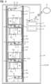
- the relay circuit of these known EBÜT80 level crossing safety systemshas electrical connecting cables 1-21, at least a majority of which are guided at least in sections in a cable duct 40, the access long side of which is provided with a detachable cover 41.
- the respective cover 141is designed to accommodate several current sensors 161-164 of the diagnostic system 130 or 230.
- the current sensors 161-164 together with the cover 141form a current sensor device 160 or 260.
- the current sensors 161-164are, for example, Hall effect sensors, which in a known manner have a sensor core SK (cf. Figure 7 ).
- the inventionis not limited to Hall effect sensors.
- sensorscan also be used that are not based on the Hall effect but on other operating principles.
- the plurality of current sensors 161-164are arranged next to one another in the longitudinal direction R1 of the cover 141 in this cover 141.
- the two embodiments 130 and 230 of the diagnostic system according to the inventiondiffer only in that the current sensors 161-164 in the first embodiment 130 are all aligned the same, while in the second embodiment 230 they are alternately rotated by 180°.
- the current sensors 161-164are preferably glued to the bottom of the cover 141 by means of double-sided adhesive strips K or are attached by means of screw connections (or comparable connections; for example plug or snap connections) that pass through the holding webs H of the current sensors 161-164.
- the width B of the cover 141corresponds to the width b of the cable duct 140. In the embodiments shown it is 50 mm.
- the depth T of the coveris less than or equal to the depth t of the cable duct.
- the diagnostic system 130 or 230comprises a data collection device 171.
- the current sensors 161-164each have a first connection A1 designed as a socket and a second connection A2 designed as a plug.
- the first connection A1is designed as a micro USB socket at one end of a first cable K1 (USB cable), in particular at least 15 cm long.
- the second connection A2is designed as a micro USB plug at one end of a second cable (USB cable), in particular at least 15 cm long.
- the multiple current sensors 161-164are connected to the data collection device 171 to form a communication bus 180 and output their measurement data to the data collection device 171 via the communication bus 180. For this purpose, they are connected to one another in series.
- the data collection device 171is designed as an Internet of Things (IoT) box, which is designed as part of a data collection arrangement 170.
- the data collection arrangement 170also includes a power supply device 172, which feeds the Internet of Things box 171 and, via the connected USB cables, also the plurality of current sensors 161-164.
- the data collection device 171(Internet of Things box) has a micro USB interface A3 - here in the form of a micro USB socket. It also has a communication interface A4, in particular an antenna, for communication with a higher-level information technology infrastructure W, which here is formed by a so-called cloud.
- the micro USB plug A2 of the first current sensor 161is plugged into a micro USB socket A5 of a USB connection cable VK.
- a micro USB plug A6 of the USB connection cable VKis plugged into the micro USB socket A3 of the Internet of Things box 171.
- the micro USB plug A2 of the second current sensor 162is plugged into the micro USB socket A1 of the first current sensor 161.
- the micro USB plug A2 of the third current sensor 163is plugged into the micro USB socket A1 of the second current sensor 162.
- the micro USB plug A2 of the fourth current sensor 164is plugged into the micro USB socket A1 of the third current sensor 163.
- the micro USB plug of the last current sensoris plugged into the micro USB socket of the penultimate current sensor, also not shown here.
- the plurality of current sensors 161-164are each designed to transmit the measurement data to the data collection device 171 by means of a Modbus transmission protocol via the communication bus 180 (Modbus RTU).
- a section 161a-164a of a respective one of the current sensors 161-164can be opened in the manner of a clamp in order to grip around one of the electrical connecting cables 1-4 assigned to it.
- the part 161a-164a of the respective current sensor 161-164which is designed in the manner of a clamp, forms together with another part of the current sensor 161b-164b a
- the respective part 161a-164a of the current sensorsprotrudes at least partially into the cable duct (see in particular the Figures 2 and 5 to 7 ).
- Each of the current sensors 161-164is a maximum of 50mm wide, a maximum of 50mm deep and a maximum of 70mm long.
- the embodiment of the current sensor shownis 45mm wide, 37.5mm deep. Its section between the retaining webs is 44mm long.
- Each of the current sensorsis designed as a direct current sensor with a measuring range of 10 to 200mA.
- the sensorsare divided into at least two sensor groups and assigned to separate cable ducts.
- several current sensorsform a first sensor group and several further current sensors form at least one further sensor group.
- one sensor groupis arranged in a cover of a cable duct and the at least one further sensor group is arranged in a further cover of a further cable duct.
- the several current sensors and the further several current sensorsare connected to a data collection device - here also forming a communication bus - and output their measurement data to the data collection device via the communication bus.
- the current sensorseach have a first connection designed as a USB socket and a second connection designed as a USB plug.
- the plug/socket combinations usedmake it possible to bridge larger distances between spatially separated sensor groups with standard micro USB cables, which have a USB socket at one end and a USB plug at the other end.
- the cover 141is provided, which is designed to accommodate several current sensors 161-164 of the diagnostic system.
- the Part 161a-164a of each of the current sensors 161-164is opened like a clamp to grip one of the electrical connecting cables 1-4 assigned to it and is closed again after the respective connecting cable 1-4 has been inserted.
- the multiple current sensors 161-164are arranged next to one another in the longitudinal direction R1 of the cover 141 and are attached using the adhesive strips K.
- the multiple current sensors 161-164output their measurement data to the data collection device 171 via the communication bus 180.
Landscapes
- Engineering & Computer Science (AREA)
- Structural Engineering (AREA)
- Civil Engineering (AREA)
- Architecture (AREA)
- Mechanical Engineering (AREA)
- Economics (AREA)
- Computing Systems (AREA)
- General Business, Economics & Management (AREA)
- Business, Economics & Management (AREA)
- Development Economics (AREA)
- Accounting & Taxation (AREA)
- Health & Medical Sciences (AREA)
- Biomedical Technology (AREA)
- General Health & Medical Sciences (AREA)
- Arrangements For Transmission Of Measured Signals (AREA)
Description
Translated fromGermanDie Erfindung betrifft ein Diagnosesystem für eine Bahnübergangssicherungsanlage.The invention relates to a diagnostic system for a level crossing safety system.
Ein derartiges Diagnosesystem ist beispielsweise aus dem Artikel "IDIS plus W95 - ein modernes Diagnosesystem für EBÜT 80", Signal + Draht (90) 11/98, Seiten 14-19 bekannt. Bei diesem Diagnosesystem ist eine spezielle Relaisschnittstelle vorgesehen, um Informationen ausgewählter Adaptionspunkte der Relaisschaltung zu erfassen und an einen Diagnose-PC auszugeben. Derartige Relaisschnittstellen erfordern hohen Entwicklungsaufwand.Such a diagnostic system is known, for example, from the article "IDIS plus W95 - a modern diagnostic system for EBÜT 80", Signal + Draht (90) 11/98, pages 14-19. This diagnostic system has a special relay interface to record information from selected adaptation points of the relay circuit and output it to a diagnostic PC. Such relay interfaces require a high level of development effort.
Die erwähnte EBÜT 80 (Einheits-Bahnübergangstechnik) beherrscht beispielsweise eine Vielzahl (bis zu 21) Schaltfälle, zu denen es wünschenswert ist, Informationen zu erfassen (vgl. "Bahnübergangs-Sicherungstechnik RBÜT realisierungsnah planen", Signal + Draht (94) 5/2002, Seiten 14-17 bekannt.The aforementioned EBÜT 80 (standard level crossing technology), for example, handles a large number (up to 21) switching cases for which it is desirable to record information (cf. "Planning level crossing safety technology RBÜT in a realistic manner", Signal + Draht (94) 5/2002, pages 14-17).
Aus der Praxis ist außerdem bekannt, dass bei einer EBÜT 80 die Relaisschaltung elektrische Verbindungskabel aufweist, von denen zumindest eine Mehrzahl zumindest abschnittsweise in einem Kabelkanal geführt ist, dessen Zugangslängsseite mit einer lösbaren Abdeckung versehen ist.It is also known from practice that in an EBÜT 80 the relay circuit has electrical connecting cables, at least a majority of which are guided at least in sections in a cable duct, the access long side of which is provided with a detachable cover.
Ferner ist aus der Druckschrift
Aus der Druckschrift
Ausgehend von einem Diagnosesystem mit den Merkmalen des Oberbegriffes des Patentanspruches 1 liegt der Erfindung die Aufgabe zu Grunde, das Diagnosesystem, insbesondere im Hinblick auf den Entwicklungsaufwand und die damit verbundenen hohen Kosten, zu vereinfachen.Starting from a diagnostic system with the features of the preamble of
Gelöst wird diese Aufgabe durch ein erfindungsgemäßes Diagnosesystem gemäß Anspruch 1, bei dem die Abdeckung zur Aufnahme mehrerer Stromsensoren des Diagnosesystems geeignet ausgebildet ist und die mehreren Stromsensoren in Längsrichtung der Abdeckung nebeneinander in dieser Abdeckung angeordnet, insbesondere befestigt, sind.This object is achieved by a diagnostic system according to the invention according to
Somit ist es möglich die gewünschten Informationen hinsichtlich der Schaltfälle ohne Verwendung einer speziellen Relaisschnittstelle zu erfassen. Die Sensoren sind somit einfach installierbar, so dass das Diagnosesystem leicht in bestehenden Bahnübergangssicherungsanlagen nachgerüstet werden kann. Vorteilhaft ist insbesondere, dass das erfindungsgemäße Diagnosesystem im Hinblick einen erforderlichen Nachweis dessen, dass es nicht auf das zu diagnostizierende Primärsystem - hier die Bahnübergangssicherungsanlage - zurückwirkt, sehr einfach und damit kostengünstig ist.This makes it possible to record the desired information regarding the switching cases without using a special relay interface. The sensors are therefore easy to install, so that the diagnostic system can easily be retrofitted into existing level crossing safety systems. It is particularly advantageous that the diagnostic system according to the invention is very simple and therefore inexpensive with regard to the necessary proof that it does not affect the primary system to be diagnosed - in this case the level crossing safety system.
Es wird als vorteilhaft angesehen, wenn die Breite der Abdeckung im Wesentlichen der Breite des Kabelkanals entspricht. Dies hat den Vorteil, der Zugang zu anderen Teilen der Bahnübergangssicherungsanlage nicht erschwert wird.It is considered advantageous if the width of the cover is essentially the same as the width of the cable duct. This has the advantage that access to other parts of the level crossing safety system is not made more difficult.
Auch wird es als vorteilhaft angesehen, wenn die Tiefe der Abdeckung kleiner oder gleich der Tiefe des Kabelkanals ist. Dies hat den Vorteil, dass die Tragfähigkeit des Kabelkanals genutzt werden kann, ohne diesen speziell stärker fixieren zu müssen.It is also considered advantageous if the depth of the cover is less than or equal to the depth of the cable duct. This has the advantage that the load-bearing capacity of the cable duct can be used without having to fix it more firmly.
In einer bevorzugten Ausgestaltung der Erfindung ist vorgesehen, dass die mehreren Stromsensoren einen Kommunikationsbus bildend an die Datensammeleinrichtung angeschlossen sind und an diese ihre Messdaten ausgeben. Damit kann insbesondere sichergestellt werden, dass die Messdaten in ihrer zeitlichen Reihenfolge korrekt erfasst werden, wobei gerade das Wissen über die zeitliche Reihenfolge der Messdaten für eine genaue Diagnose der Schaltfälle von besonderem Vorteil ist.In a preferred embodiment of the invention, the multiple current sensors are connected to the data collection device to form a communication bus and output their measurement data to the data collection device. This ensures in particular that the measurement data are recorded correctly in their chronological order, with knowledge of the chronological order of the measurement data being particularly advantageous for an accurate diagnosis of the switching cases.
Es wird als vorteilhaft angesehen, wenn die Stromsensoren geeignet ausgebildet sind, die Messdaten mittels eines seriellen Übertragungsprotokolls über den Kommunikationsbus an die Datensammeleinrichtung zu übertragen. Als Kommunikationsbus kann beispielsweise ein Modbus, insbesondere ein Modbus RTU, zum Einsatz kommen.It is considered advantageous if the current sensors are designed to transmit the measurement data to the data collection device using a serial transmission protocol via the communication bus. A Modbus, in particular a Modbus RTU, can be used as the communication bus, for example.
Vorzugsweise ist die Datensammeleinrichtung als eine Internet-der-Dinge-Box (dem Fachmann bekannt unter der englischen Bezeichnung: Internet of Things Box, kurz IoT-Box) ausgebildet, welche eine Kommunikationsschnittstelle, insbesondere eine Antenne, zur Kommunikation mit einer übergeordneten Informationstechnik-Infrastruktur, welche beispielsweise in Form einer Cloud vorliegt, aufweist.Preferably, the data collection device is designed as an Internet of Things box (known to those skilled in the art by the English name: Internet of Things box, or IoT box for short), which has a communication interface, in particular an antenna, for communication with a higher-level information technology infrastructure, which is in the form of a cloud, for example.
Die Erfindung betrifft auch einen Stromsensor gemäß Anspruch 7 für ein erfindungsgemäßes Diagnosesystem, bei welchem ein Abschnitt zum Umgreifen eines ihm zugeordneten der elektrischen Verbindungskabel nach Art einer Schelle öffenbar ist.The invention also relates to a current sensor according to
Es wird als vorteilhaft angesehen, wenn der Teil des Stromsensors, welcher nach Art einer Schelle ausgebildet ist, einen Teil eines Sensorkerns bildet und zumindest teilweise in den Kabelkanal hineinragt.It is considered advantageous if the part of the current sensor which is designed in the manner of a clamp forms part of a sensor core and at least partially projects into the cable duct.
Es ist vorgesehen, dass der Stromsensor maximal 50mm breit, maximal 50mm tief und maximal 70mm lang ist, um möglichst wenig Bauraum zu beanspruchen.The current sensor is intended to be a maximum of 50mm wide, 50mm deep and 70mm long in order to use as little installation space as possible.
Vorzugsweise ist der Stromsensor weniger als 45mm breit, weniger als 40mm tief und weniger als 45mm lang.Preferably, the current sensor is less than 45mm wide, less than 40mm deep and less than 45mm long.
Vorzugsweise ist der Stromsensor als Gleichstromsensor mit einem Messbereich von 10 bis 200mA ausgebildet.Preferably, the current sensor is designed as a direct current sensor with a measuring range of 10 to 200 mA.
Es wird ferner als vorteilhaft angesehen, wenn der Stromsensor jeweils einen als Buchse ausgebildeten ersten Anschluss und einen als Stecker ausgebildeten zweiten Anschluss aufweist, wobei der erste Anschluss an einem Kabelende eines, insbesondere zumindest 15 cm langen, ersten Kabels als Micro USB-Buchse ausgebildet ist und wobei der zweite Anschluss an einem Kabelende eines, insbesondere zumindest 15 cm langen, zweiten Kabels als Micro USB-Stecker ausgebildet ist.It is further considered advantageous if the current sensor has a first connection designed as a socket and a second connection designed as a plug, wherein the first connection is designed as a micro USB socket at one cable end of a first cable, in particular at least 15 cm long, and wherein the second connection is designed as a micro USB plug at one cable end of a second cable, in particular at least 15 cm long.
Die Erfindung betrifft außerdem ein Verfahren gemäß Anspruch 14 zur Installation eines Diagnosesystems in einer Bahnübergangssicherungsanlage, deren Relaisschaltung elektrische Verbindungskabel aufweist, von denen zumindest eine Mehrzahl zumindest abschnittsweise in einem Kabelkanal geführt ist, dessen Zugangslängsseite mit einer lösbaren Abdeckung versehen ist. Erfindungsgemäß wird die Abdeckung zur Aufnahme mehrerer Stromsensoren des Diagnosesystems geeignet bereitgestellt und es werden mehrere Stromsensoren in Längsrichtung der Abdeckung nebeneinander in dieser Abdeckung angeordnet, insbesondere befestigt, wobei ein Abschnitt eines jeweiligen der Stromsensoren zum Umgreifen eines ihm zugeordneten der elektrischen Verbindungskabel nach Art einer Schelle geöffnet und nach dem Einlegen des Verbindungskabels wieder geschlossen wird.The invention also relates to a method according to
Vorzugsweise werden die mehreren Stromsensoren einen Kommunikationsbus bildend an eine Datensammeleinrichtung angeschlossen und geben ihre Messdaten, insbesondere mittels eines seriellen Übertragungsprotokolls, an diese Datensammeleinrichtung aus. Wie bereits erwähnt, kann als Kommunikationsbus beispielsweise ein Modbus, insbesondere ein Modbus RTU, zum Einsatz kommen.Preferably, the multiple current sensors are connected to a data collection device to form a communication bus and output their measurement data to this data collection device, in particular by means of a serial transmission protocol. As already mentioned, a Modbus, in particular a Modbus RTU, can be used as the communication bus.
Die Erfindung ist im Weiteren anhand der
Figur 1- eine schematische Darstellung einer Bahnübergangssicherungsanlage mit Diagnosesystem nach dem Stand der Technik, die
Figur 2- eine schematische Darstellung einer Bahnübergangssicherungsanlage mit einer ersten Ausführungsform des erfindungsgemäßen Diagnosesystems, die
Figur 3- eine Schnittdarstellung der ersten Ausführungsform des erfindungsgemäßen Diagnosesystems entlang der Linie III-III in
Figur 2 Figur 4- eine Schnittdarstellung einer zweiten Ausführungsform des erfindungsgemäßen Diagnosesystems und die
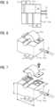
Figuren 5 bis 7- verschiedene Ansichten eines Stromsensors des erfindungsgemäßen Diagnosesystems.
- Figure 1
- a schematic representation of a level crossing safety system with diagnostic system according to the state of the art, the
- Figure 2
- a schematic representation of a level crossing safety system with a first embodiment of the diagnostic system according to the invention, the
- Figure 3
- a sectional view of the first embodiment of the diagnostic system according to the invention along the line III-III in
Figure 2 , the - Figure 4
- a sectional view of a second embodiment of the diagnostic system according to the invention and the
- Figures 5 to 7
- different views of a current sensor of the diagnostic system according to the invention.
Gemäß der
Bei der in den
Die Stromsensoren 161-164 sind beispielsweise Hall-Effekt-Sensoren, welche in bekannter Weise einen Sensorkern SK (vgl.
Gemäß den
Die beiden Ausführungsformen 130 und 230 des erfindungsgemäßen Diagnosesystems unterscheiden sich lediglich dahingehend, dass die Stromsensoren 161-164 bei der ersten Ausführungsform 130 alle gleich ausgerichtet sind, während sie bei der zweiten Ausführungsformen 230 wechselweise um 180° gedreht sind.The two
Die Stromsensoren 161-164 sind vorzugsweise mittels doppelseitiger Klebestreifen K am Boden der Abdeckung 141 angeklebt oder aber mittels Schraubverbindungen (bzw. damit vergleichbarer Verbindungen; beispielsweise Steck- oder Rastverbindungen), die Haltestege H der Stromsensoren 161-164 durchgreifen befestigt.The current sensors 161-164 are preferably glued to the bottom of the
Die Breite B der Abdeckung 141 entspricht der Breite b des Kabelkanals 140 Sie beträgt bei den gezeigten Ausführungsformen 50mm.The width B of the
Die Tiefe T der Abdeckung ist kleiner oder gleich der Tiefe t des Kabelkanals ist.The depth T of the cover is less than or equal to the depth t of the cable duct.
Das Diagnosesystem 130 bzw. 230 umfasst eine Datensammeleinrichtung 171.The
Die Stromsensoren 161-164 weisen jeweils einen als Buchse ausgebildeten ersten Anschluss A1 und einen als Stecker ausgebildeten zweiten Anschluss A2 auf. Der erste Anschluss A1 ist an einem Kabelende eines, insbesondere zumindest 15 cm langen, ersten Kabels K1 (USB-Kabel) als Micro USB-Buchse ausgebildet ist. Der zweite Anschluss A2 ist an einem Kabelende eines, insbesondere zumindest 15 cm langen, zweiten Kabels (USB-Kabel) K2 als Micro USB-Stecker ausgebildet ist.The current sensors 161-164 each have a first connection A1 designed as a socket and a second connection A2 designed as a plug. The first connection A1 is designed as a micro USB socket at one end of a first cable K1 (USB cable), in particular at least 15 cm long. The second connection A2 is designed as a micro USB plug at one end of a second cable (USB cable), in particular at least 15 cm long.
Die mehreren Stromsensoren 161-164 sind einen Kommunikationsbus 180 bildend an die Datensammeleinrichtung 171 angeschlossen und geben über den Kommunikationsbus 180 ihre Messdaten an die Datensammeleinrichtung 171 aus. Hierzu sie in Reihe miteinander verbunden.The multiple current sensors 161-164 are connected to the
Die Datensammeleinrichtung 171 ist als eine Internet-der-Dinge-Box (IoT-Box) ausgebildet, welche als Teil einer Datensammelanordnung 170 ausgebildet ist. Zu der Datensammelanordnung 170 gehört auch eine Stromversorgungseinrichtung 172, welche die Internet-der-Dinge-Box 171 und über die verbundenen USB-Kabel auch die mehreren Stromsensoren 161-164 speist.The
Die Datensammeleinrichtung 171 (Internet-der-Dinge-Box) weist eine Micro-USB-Schnittstelle A3 - hier in Form einer Micro USB-Buchse - auf. Außerdem weist sie eine Kommunikationsschnittstelle A4, insbesondere eine Antenne, zur Kommunikation mit einer übergeordneten Informationstechnik-Infrastruktur W auf, welche hier von einer sogenannten Cloud gebildet ist.The data collection device 171 (Internet of Things box) has a micro USB interface A3 - here in the form of a micro USB socket. It also has a communication interface A4, in particular an antenna, for communication with a higher-level information technology infrastructure W, which here is formed by a so-called cloud.
Wie gezeigt ist der Micro USB-Stecker A2 des ersten Stromsensors 161 in eine die Micro USB-Buchse A5 eines USB-Verbindungskabels VK eingesteckt. Ein Micro USB-Stecker A6 des USB-Verbindungskabels VK ist in die Micro USB-Buchse A3 der Internet-der-Dinge-Box 171 eingesteckt.As shown, the micro USB plug A2 of the first
Der Micro USB-Stecker A2 des zweiten Stromsensors 162 ist in die Micro USB-Buchse A1 des ersten Stromsensors 161 eingesteckt. Der Micro USB-Stecker A2 des dritten Stromsensors 163 ist in die Micro USB-Buchse A1 des zweiten Stromsensors 162 eingesteckt. Der Micro USB-Stecker A2 des vierten Stromsensors 164 ist in die Micro USB-Buchse A1 des dritten Stromsensors 163 eingesteckt. Und der Micro USB-Stecker des hier nicht gezeigte letzten Stromsensor ist in die Micro USB-Buchse des hier ebenfalls nicht gezeigten vorletzten Stromsensors eingesteckt.The micro USB plug A2 of the second
Die mehreren Stromsensoren 161-164 sind jeweils geeignet ausgebildet die Messdaten mittels eines Modbus Übertragungsprotokolls über den Kommunikationsbus 180 (Modbus RTU) an die Datensammeleinrichtung 171 zu übertragen.The plurality of current sensors 161-164 are each designed to transmit the measurement data to the
Wie die Figuren zeigen, ist ein Abschnitt 161a-164a eines jeweiligen der Stromsensoren 161-164 zum Umgreifen eines ihm zugeordneten der elektrischen Verbindungskabel 1-4 nach Art einer Schelle öffenbar.As the figures show, a
Der Teil 161a-164a des jeweiligen Stromsensors 161-164, welcher nach Art einer Schelle ausgebildet ist, bildet zusammen mit einem weiteren Teil des Stromsensors 161b-164b einen zu schließenden Sensorkern. Der jeweilige Teil 161a-164a der Stromsensoren ragt zumindest teilweise in den Kabelkanal hinein (siehe insbesondere die
Jeder der Stromsensoren 161-164 ist maximal 50mm breit, maximal 50mm tief und maximal 70mm lang. Die gezeigte Ausführungsform des Stromsensors ist 45mm breit, 37,5 mm tief. Sein Abschnitt zwischen den Haltestegen ist 44mm lang.Each of the current sensors 161-164 is a maximum of 50mm wide, a maximum of 50mm deep and a maximum of 70mm long. The embodiment of the current sensor shown is 45mm wide, 37.5mm deep. Its section between the retaining webs is 44mm long.
Jeder der Stromsensoren ist als Gleichstromsensor mit einem Messbereich von 10 bis 200mA ausgebildet.Each of the current sensors is designed as a direct current sensor with a measuring range of 10 to 200mA.
Bei einer weiteren, hier nicht dargestellten Ausführungsform des erfindungsgemäßen Diagnosesystems sind die Sensoren in zumindest zwei Sensorgruppen aufgeteilt und separaten Kabelkanälen zugeordnet. Es bilden also mehrere Stromsensoren eine erste Sensorgruppe und mehrere weitere Stromsensoren bilden zumindest eine weitere Sensorgruppe. Dabei ist die eine Sensorgruppe wie bei den beiden ersten Ausführungsformen des erfindungsgemäßen Diagnosesystems in einer Abdeckung eines Kabelkanals angeordnet und die zumindest eine weitere Sensorgruppe ist in einer weiteren Abdeckung eines weiteren Kabelkanals angeordnet. Die mehreren Stromsensoren und die weiteren mehreren Stromsensoren sind - auch hier einen Kommunikationsbus bildend - an eine Datensammeleinrichtung angeschlossen und geben über den Kommunikationsbus ihre Messdaten an die Datensammeleinrichtung aus. Die Stromsensoren weisen auch hierbei jeweils einen als USB-Buchse ausgebildeten ersten Anschluss und einen als USB-Stecker ausgebildeten zweiten Anschluss auf. Durch die verwendeten Stecker-/Buchse-Kombinationen ist es möglich, größere Abstände zwischen den räumlich abgesetzten Sensorgruppen mit standard-Micro-USB-Kabeln, welche an einem Ende eine USB-Buchse und am anderen Ende einen USB-Stecker ausweisen, zu überbrücken.In a further embodiment of the diagnostic system according to the invention, not shown here, the sensors are divided into at least two sensor groups and assigned to separate cable ducts. Thus, several current sensors form a first sensor group and several further current sensors form at least one further sensor group. As in the first two embodiments of the diagnostic system according to the invention, one sensor group is arranged in a cover of a cable duct and the at least one further sensor group is arranged in a further cover of a further cable duct. The several current sensors and the further several current sensors are connected to a data collection device - here also forming a communication bus - and output their measurement data to the data collection device via the communication bus. Here, too, the current sensors each have a first connection designed as a USB socket and a second connection designed as a USB plug. The plug/socket combinations used make it possible to bridge larger distances between spatially separated sensor groups with standard micro USB cables, which have a USB socket at one end and a USB plug at the other end.
Zur Installation der Stromsensoren wird die Abdeckung 141 bereitgestellt, welche zur Aufnahme der mehrerer Stromsensoren 161-164 des Diagnosesystems geeignet ausgebildet ist. Der Teil 161a-164a eines jeweiligen der Stromsensoren 161-164 wird zum Umgreifen eines ihm zugeordneten der elektrischen Verbindungskabel 1-4 nach Art einer Schelle geöffnet und nach dem Einlegen des jeweiligen Verbindungskabels 1-4 wieder geschlossen. Die mehreren Stromsensoren 161-164 werden in Längsrichtung R1 der Abdeckung 141 nebeneinander in dieser Abdeckung 141 angeordnet und mittels der Klebestreifen K befestigt. Die mehreren Stromsensoren 161-164 geben über den Kommunikationsbus 180 ihre Messdaten an die Datensammeleinrichtung 171 aus.For installation of the current sensors, the
Claims (15)
- Diagnostic system (130;230) for a level crossing safeguarding system (EBÜT80), of which the relay circuit has electrical connection cables (1-21), of which at least a plurality are guided in a cable duct (140), at least in sections, of which the access longitudinal side is provided with a detachable covering (141),
characterised in thatthe cover (141) is suitably embodied for accommodating a plurality of current sensors (161-164) of the diagnostic system (130;230) andthe plurality of current sensors (161-164) are arranged, in particular fastened, adjacent to one another in the longitudinal direction (R1) of the covering (141) in said covering. - Diagnostic system (130;230) according to claim 1,
characterised in that
the width (B) of the covering (141) corresponds to the width (b) of the cable duct. - Diagnostic system (130;230) according to one of claims 1 or 2,
characterised in that
the depth (T) of the covering is less than or equal to the depth (t) of the cable duct. - Diagnostic system (130;230) according to one of claims 1 to 3,
characterised bya data collection facility (171),wherein the plurality of current sensors (161-164), forming a communication bus (180), are connected to the data collection facility (171) and output their measurement data to said data collection facility. - Diagnostic system (130;230) according to claim 4,
characterised in that
the current sensors (161-164) are suitably embodied to transfer the measurement data to the data collection facility (171) by means of a serial transfer protocol via the communication bus (180). - Diagnostic system (130;230) according to one of claims 4 or 5,
characterised in that
the data collection facility (171) is embodied as an Internet of Things box, which has a communication interface (A4), in particular an antenna, for communicating with a higher-level information technology infrastructure (W). - Current sensor (161-164) for a diagnostic system (130;230) according to one of claims 1 to 6,
characterised in that
a section (161a-164a) of the current sensor can be opened in order to encompass one of the electrical connection cables (1-4) that is assigned to it in the manner of a clamp. - Current sensor (161-164) according to claim 7,
characterised in that
the part of the current sensor that is embodied in the manner of a clamp forms a part of a sensor core (SK) and protrudes at least partially into the cable duct (140). - Current sensor (161-164) according to one of claims 7 or 8,characterised in that
the current sensor is at most 50mm wide, preferably less than 45mm wide. - Current sensor (161-164) according to one of claims 7 to 9,
characterised in that
the current sensor is at most 50mm deep, preferably less than 40mm deep. - Current sensor (161-164) according to one of claims 7 to 10,
characterised in that
the current sensor is at most 70mm long, preferably less than 45mm long. - Current sensor (161-164) according to one of claims 7 to 11,
characterised in that
the current sensor is embodied as a direct current sensor with a measurement range from 10 to 200mA. - Current sensor (161-164) according to one of claims 7 to 12,
characterised in thatthe current sensor in each case has a first connection (A1) embodied as a socket and a second connection (A2) embodied as a plug,wherein the first connection is embodied as a Micro USB socket at one cable end of a first cable (K1), which in particular is at least 15 cm long, andwherein the second connection is embodied as a Micro USB plug at one cable end of a second cable (K2), which in particular is at least 15 cm long. - Method for installing a diagnostic system in a level crossing safeguarding system, of which the relay circuit has electrical connection cables, of which at least a plurality are guided in a cable duct, at least in sections, of which the access longitudinal side is provided with a detachable covering,
characterised in thatthe covering is suitably provided to accommodate a plurality of current sensors of the diagnostic system, and a plurality of current sensors are arranged, in particular fastened, adjacent to one another in the longitudinal direction of the covering in said covering,wherein a section of a respective one of the current sensors is opened in order to encompass one of the electrical connection cables that is assigned to it in the manner of a clamp, and is closed again once the connection cable has been inserted. - Method according to claim 14,
characterised in that
the plurality of current sensors, forming a communication bus, are connected to a data collection facility and output their measurement data to said data collection facility, in particular by means of a serial transfer protocol.
Applications Claiming Priority (3)
| Application Number | Priority Date | Filing Date | Title |
|---|---|---|---|
| DE102019208017 | 2019-05-31 | ||
| DE102019209237.3ADE102019209237A1 (en) | 2019-05-31 | 2019-06-26 | Diagnostic system for a level crossing safety system, current sensor for such a diagnostic system and method for installing such a diagnostic system |
| PCT/EP2020/063034WO2020239419A1 (en) | 2019-05-31 | 2020-05-11 | Diagnostic system for a level-crossing safeguarding system, current sensor for such a diagnostic system, and method for installing such a diagnostic system |
Publications (3)
| Publication Number | Publication Date |
|---|---|
| EP3956197A1 EP3956197A1 (en) | 2022-02-23 |
| EP3956197B1true EP3956197B1 (en) | 2024-10-30 |
| EP3956197C0 EP3956197C0 (en) | 2024-10-30 |
Family
ID=73264833
Family Applications (1)
| Application Number | Title | Priority Date | Filing Date |
|---|---|---|---|
| EP20728959.6AActiveEP3956197B1 (en) | 2019-05-31 | 2020-05-11 | Diagnostic system for a level-crossing safeguarding system, current sensor for such a diagnostic system, and method for installing such a diagnostic system |
Country Status (5)
| Country | Link |
|---|---|
| US (1) | US12095246B2 (en) |
| EP (1) | EP3956197B1 (en) |
| DE (1) | DE102019209237A1 (en) |
| ES (1) | ES3007860T3 (en) |
| WO (1) | WO2020239419A1 (en) |
Family Cites Families (6)
| Publication number | Priority date | Publication date | Assignee | Title |
|---|---|---|---|---|
| US5735492A (en) | 1991-02-04 | 1998-04-07 | Pace; Joseph A. | Railroad crossing traffic warning system apparatus and method therefore |
| NO178559C (en) | 1993-06-01 | 1996-04-17 | Nkt Holding As | Feed device with connecting means |
| WO2009137817A1 (en)* | 2008-05-08 | 2009-11-12 | Outsmart Power Systems Llc | Device and method for measuring current and power in a plug or receptacle |
| US20130256466A1 (en)* | 2012-04-03 | 2013-10-03 | Metrom Rail, Llc | Rail crossing remote diagnostics |
| WO2014059487A1 (en) | 2012-10-18 | 2014-04-24 | Siemens Ltd. | Supplementary warning system for level crossing activated by train |
| DE102015201440A1 (en) | 2015-01-28 | 2016-07-28 | Bayerische Motoren Werke Aktiengesellschaft | Supply rail for a motor vehicle |
- 2019
- 2019-06-26DEDE102019209237.3Apatent/DE102019209237A1/ennot_activeWithdrawn
- 2020
- 2020-05-11WOPCT/EP2020/063034patent/WO2020239419A1/ennot_activeCeased
- 2020-05-11EPEP20728959.6Apatent/EP3956197B1/enactiveActive
- 2020-05-11USUS17/615,250patent/US12095246B2/enactiveActive
- 2020-05-11ESES20728959Tpatent/ES3007860T3/enactiveActive
Also Published As
| Publication number | Publication date |
|---|---|
| ES3007860T3 (en) | 2025-03-20 |
| EP3956197A1 (en) | 2022-02-23 |
| WO2020239419A1 (en) | 2020-12-03 |
| US20220239079A1 (en) | 2022-07-28 |
| DE102019209237A1 (en) | 2020-12-03 |
| EP3956197C0 (en) | 2024-10-30 |
| US12095246B2 (en) | 2024-09-17 |
Similar Documents
| Publication | Publication Date | Title |
|---|---|---|
| DE2414566C2 (en) | Electric automatic system | |
| EP1174781B1 (en) | Signal transmission apparatus | |
| EP0015309A1 (en) | Device for pressing an optical waveguide against a photoelectrical element | |
| EP0436804A2 (en) | Electrical installation unit for domestic applications | |
| WO2021083734A1 (en) | Measurement system for electrical conductors, in particular hv conductors | |
| DE102017108183B4 (en) | Electronic module for coupling to a module arrangement and module arrangement | |
| DE69115402T2 (en) | Wiring structure for interior structures | |
| EP0909121B1 (en) | Electronic I/O module | |
| EP3956197B1 (en) | Diagnostic system for a level-crossing safeguarding system, current sensor for such a diagnostic system, and method for installing such a diagnostic system | |
| DE6908176U (en) | DEVICE FOR THE PRODUCTION OF INTERMEDIATE CONNECTIONS | |
| EP2693280B1 (en) | Street construction machine with measuring system and measuring method | |
| DE29723752U1 (en) | Electronic device | |
| DE102015105548A1 (en) | Rangierwabe | |
| DE2340773A1 (en) | Transfer plug connector for wiring system with spring strip - has terminal pins protruding above wiring plane for connection to respective cct. boards | |
| DE102011004873B4 (en) | Ribbon cable sheath for AS-Interface systems | |
| EP4080691A1 (en) | Mounting rail for lights or electrical units | |
| DE2654317C3 (en) | Arrangement of electrical communications equipment, especially radio relay technology | |
| WO2004021059A1 (en) | Connector plug | |
| EP2214416B1 (en) | Patch panel and method for its installation | |
| DE202011107955U1 (en) | Electrohydraulic actuator | |
| DE202018106893U1 (en) | Busbar adapter | |
| DE102020202209B4 (en) | Arrangement of electronic modules | |
| DE102007028643A1 (en) | Series integrated device ensemble is made of multiple series integrated devices connected to bus line, which is guided on one of device collars | |
| DE60200782T2 (en) | Comb and method for branching for an existing line | |
| DE10331441A1 (en) | Contact insert for connecting multi-core cable conductor, uses recess, especially slot, for locking movably arranged latching element for fixing contact insert in housing |
Legal Events
| Date | Code | Title | Description |
|---|---|---|---|
| STAA | Information on the status of an ep patent application or granted ep patent | Free format text:STATUS: UNKNOWN | |
| STAA | Information on the status of an ep patent application or granted ep patent | Free format text:STATUS: THE INTERNATIONAL PUBLICATION HAS BEEN MADE | |
| PUAI | Public reference made under article 153(3) epc to a published international application that has entered the european phase | Free format text:ORIGINAL CODE: 0009012 | |
| STAA | Information on the status of an ep patent application or granted ep patent | Free format text:STATUS: REQUEST FOR EXAMINATION WAS MADE | |
| 17P | Request for examination filed | Effective date:20211118 | |
| AK | Designated contracting states | Kind code of ref document:A1 Designated state(s):AL AT BE BG CH CY CZ DE DK EE ES FI FR GB GR HR HU IE IS IT LI LT LU LV MC MK MT NL NO PL PT RO RS SE SI SK SM TR | |
| DAV | Request for validation of the european patent (deleted) | ||
| DAX | Request for extension of the european patent (deleted) | ||
| REG | Reference to a national code | Ref country code:DE Ref legal event code:R079 Free format text:PREVIOUS MAIN CLASS: B61L0027000000 Ipc:B61L0029300000 Ref country code:DE Ref legal event code:R079 Ref document number:502020009628 Country of ref document:DE Free format text:PREVIOUS MAIN CLASS: B61L0027000000 Ipc:B61L0029300000 | |
| GRAP | Despatch of communication of intention to grant a patent | Free format text:ORIGINAL CODE: EPIDOSNIGR1 | |
| STAA | Information on the status of an ep patent application or granted ep patent | Free format text:STATUS: GRANT OF PATENT IS INTENDED | |
| RIC1 | Information provided on ipc code assigned before grant | Ipc:H02G 3/04 20060101ALN20240514BHEP Ipc:B61L 27/53 20220101ALI20240514BHEP Ipc:B61L 29/30 20060101AFI20240514BHEP | |
| INTG | Intention to grant announced | Effective date:20240605 | |
| GRAS | Grant fee paid | Free format text:ORIGINAL CODE: EPIDOSNIGR3 | |
| GRAA | (expected) grant | Free format text:ORIGINAL CODE: 0009210 | |
| STAA | Information on the status of an ep patent application or granted ep patent | Free format text:STATUS: THE PATENT HAS BEEN GRANTED | |
| AK | Designated contracting states | Kind code of ref document:B1 Designated state(s):AL AT BE BG CH CY CZ DE DK EE ES FI FR GB GR HR HU IE IS IT LI LT LU LV MC MK MT NL NO PL PT RO RS SE SI SK SM TR | |
| REG | Reference to a national code | Ref country code:GB Ref legal event code:FG4D Free format text:NOT ENGLISH | |
| REG | Reference to a national code | Ref country code:CH Ref legal event code:EP | |
| REG | Reference to a national code | Ref country code:IE Ref legal event code:FG4D Free format text:LANGUAGE OF EP DOCUMENT: GERMAN | |
| REG | Reference to a national code | Ref country code:DE Ref legal event code:R096 Ref document number:502020009628 Country of ref document:DE | |
| U01 | Request for unitary effect filed | Effective date:20241115 | |
| U07 | Unitary effect registered | Designated state(s):AT BE BG DE DK EE FI FR IT LT LU LV MT NL PT RO SE SI Effective date:20241122 | |
| REG | Reference to a national code | Ref country code:ES Ref legal event code:FG2A Ref document number:3007860 Country of ref document:ES Kind code of ref document:T3 Effective date:20250320 | |
| PG25 | Lapsed in a contracting state [announced via postgrant information from national office to epo] | Ref country code:IS Free format text:LAPSE BECAUSE OF FAILURE TO SUBMIT A TRANSLATION OF THE DESCRIPTION OR TO PAY THE FEE WITHIN THE PRESCRIBED TIME-LIMIT Effective date:20250228 Ref country code:HR Free format text:LAPSE BECAUSE OF FAILURE TO SUBMIT A TRANSLATION OF THE DESCRIPTION OR TO PAY THE FEE WITHIN THE PRESCRIBED TIME-LIMIT Effective date:20241030 | |
| PG25 | Lapsed in a contracting state [announced via postgrant information from national office to epo] | Ref country code:NO Free format text:LAPSE BECAUSE OF FAILURE TO SUBMIT A TRANSLATION OF THE DESCRIPTION OR TO PAY THE FEE WITHIN THE PRESCRIBED TIME-LIMIT Effective date:20250130 | |
| PG25 | Lapsed in a contracting state [announced via postgrant information from national office to epo] | Ref country code:GR Free format text:LAPSE BECAUSE OF FAILURE TO SUBMIT A TRANSLATION OF THE DESCRIPTION OR TO PAY THE FEE WITHIN THE PRESCRIBED TIME-LIMIT Effective date:20250131 | |
| PG25 | Lapsed in a contracting state [announced via postgrant information from national office to epo] | Ref country code:PL Free format text:LAPSE BECAUSE OF FAILURE TO SUBMIT A TRANSLATION OF THE DESCRIPTION OR TO PAY THE FEE WITHIN THE PRESCRIBED TIME-LIMIT Effective date:20241030 | |
| PG25 | Lapsed in a contracting state [announced via postgrant information from national office to epo] | Ref country code:RS Free format text:LAPSE BECAUSE OF FAILURE TO SUBMIT A TRANSLATION OF THE DESCRIPTION OR TO PAY THE FEE WITHIN THE PRESCRIBED TIME-LIMIT Effective date:20250130 | |
| U20 | Renewal fee for the european patent with unitary effect paid | Year of fee payment:6 Effective date:20250520 | |
| PG25 | Lapsed in a contracting state [announced via postgrant information from national office to epo] | Ref country code:SM Free format text:LAPSE BECAUSE OF FAILURE TO SUBMIT A TRANSLATION OF THE DESCRIPTION OR TO PAY THE FEE WITHIN THE PRESCRIBED TIME-LIMIT Effective date:20241030 | |
| PGFP | Annual fee paid to national office [announced via postgrant information from national office to epo] | Ref country code:GB Payment date:20250610 Year of fee payment:6 | |
| PG25 | Lapsed in a contracting state [announced via postgrant information from national office to epo] | Ref country code:SK Free format text:LAPSE BECAUSE OF FAILURE TO SUBMIT A TRANSLATION OF THE DESCRIPTION OR TO PAY THE FEE WITHIN THE PRESCRIBED TIME-LIMIT Effective date:20241030 | |
| PG25 | Lapsed in a contracting state [announced via postgrant information from national office to epo] | Ref country code:CZ Free format text:LAPSE BECAUSE OF FAILURE TO SUBMIT A TRANSLATION OF THE DESCRIPTION OR TO PAY THE FEE WITHIN THE PRESCRIBED TIME-LIMIT Effective date:20241030 | |
| PLBE | No opposition filed within time limit | Free format text:ORIGINAL CODE: 0009261 | |
| STAA | Information on the status of an ep patent application or granted ep patent | Free format text:STATUS: NO OPPOSITION FILED WITHIN TIME LIMIT | |
| 26N | No opposition filed | Effective date:20250731 | |
| PGFP | Annual fee paid to national office [announced via postgrant information from national office to epo] | Ref country code:ES Payment date:20250825 Year of fee payment:6 |