EP3953009B1 - Suspended theater edge actuated seat moving machine - Google Patents
Suspended theater edge actuated seat moving machineDownload PDFInfo
- Publication number
- EP3953009B1 EP3953009B1EP20787615.2AEP20787615AEP3953009B1EP 3953009 B1EP3953009 B1EP 3953009B1EP 20787615 AEP20787615 AEP 20787615AEP 3953009 B1EP3953009 B1EP 3953009B1
- Authority
- EP
- European Patent Office
- Prior art keywords
- lift arm
- passenger seat
- seat
- passenger
- actuator
- Prior art date
- Legal status (The legal status is an assumption and is not a legal conclusion. Google has not performed a legal analysis and makes no representation as to the accuracy of the status listed.)
- Active
Links
Images


Classifications
- A—HUMAN NECESSITIES
- A63—SPORTS; GAMES; AMUSEMENTS
- A63J—DEVICES FOR THEATRES, CIRCUSES, OR THE LIKE; CONJURING APPLIANCES OR THE LIKE
- A63J5/00—Auxiliaries for producing special effects on stages, or in circuses or arenas
- A—HUMAN NECESSITIES
- A47—FURNITURE; DOMESTIC ARTICLES OR APPLIANCES; COFFEE MILLS; SPICE MILLS; SUCTION CLEANERS IN GENERAL
- A47C—CHAIRS; SOFAS; BEDS
- A47C1/00—Chairs adapted for special purposes
- A47C1/12—Theatre, auditorium or similar chairs
- A—HUMAN NECESSITIES
- A47—FURNITURE; DOMESTIC ARTICLES OR APPLIANCES; COFFEE MILLS; SPICE MILLS; SUCTION CLEANERS IN GENERAL
- A47C—CHAIRS; SOFAS; BEDS
- A47C1/00—Chairs adapted for special purposes
- A47C1/12—Theatre, auditorium or similar chairs
- A47C1/124—Separate chairs, connectible together into a row
- A—HUMAN NECESSITIES
- A63—SPORTS; GAMES; AMUSEMENTS
- A63G—MERRY-GO-ROUNDS; SWINGS; ROCKING-HORSES; CHUTES; SWITCHBACKS; SIMILAR DEVICES FOR PUBLIC AMUSEMENT
- A63G31/00—Amusement arrangements
- A63G31/02—Amusement arrangements with moving substructures
- A—HUMAN NECESSITIES
- A63—SPORTS; GAMES; AMUSEMENTS
- A63G—MERRY-GO-ROUNDS; SWINGS; ROCKING-HORSES; CHUTES; SWITCHBACKS; SIMILAR DEVICES FOR PUBLIC AMUSEMENT
- A63G31/00—Amusement arrangements
- A63G31/16—Amusement arrangements creating illusions of travel
- A—HUMAN NECESSITIES
- A63—SPORTS; GAMES; AMUSEMENTS
- A63J—DEVICES FOR THEATRES, CIRCUSES, OR THE LIKE; CONJURING APPLIANCES OR THE LIKE
- A63J25/00—Equipment specially adapted for cinemas
- A—HUMAN NECESSITIES
- A63—SPORTS; GAMES; AMUSEMENTS
- A63J—DEVICES FOR THEATRES, CIRCUSES, OR THE LIKE; CONJURING APPLIANCES OR THE LIKE
- A63J3/00—Equipment for, or arrangement of, circuses or arenas
- A—HUMAN NECESSITIES
- A63—SPORTS; GAMES; AMUSEMENTS
- A63J—DEVICES FOR THEATRES, CIRCUSES, OR THE LIKE; CONJURING APPLIANCES OR THE LIKE
- A63J5/00—Auxiliaries for producing special effects on stages, or in circuses or arenas
- A63J5/12—Apparatus for raising or lowering persons
- E—FIXED CONSTRUCTIONS
- E04—BUILDING
- E04H—BUILDINGS OR LIKE STRUCTURES FOR PARTICULAR PURPOSES; SWIMMING OR SPLASH BATHS OR POOLS; MASTS; FENCING; TENTS OR CANOPIES, IN GENERAL
- E04H3/00—Buildings or groups of buildings for public or similar purposes; Institutions, e.g. infirmaries or prisons
- E04H3/10—Buildings or groups of buildings for public or similar purposes; Institutions, e.g. infirmaries or prisons for meetings, entertainments, or sports
- E04H3/22—Theatres; Concert halls; Studios for broadcasting, cinematography, television or similar purposes
- E04H3/30—Constructional features of auditoriums
- A—HUMAN NECESSITIES
- A63—SPORTS; GAMES; AMUSEMENTS
- A63G—MERRY-GO-ROUNDS; SWINGS; ROCKING-HORSES; CHUTES; SWITCHBACKS; SIMILAR DEVICES FOR PUBLIC AMUSEMENT
- A63G27/00—Russian swings; Great wheels, e.g. Ferris wheels
- A63G27/02—Russian swings; Great wheels, e.g. Ferris wheels with special movements of the seat-carriers
- A—HUMAN NECESSITIES
- A63—SPORTS; GAMES; AMUSEMENTS
- A63J—DEVICES FOR THEATRES, CIRCUSES, OR THE LIKE; CONJURING APPLIANCES OR THE LIKE
- A63J5/00—Auxiliaries for producing special effects on stages, or in circuses or arenas
- A63J2005/001—Auxiliaries for producing special effects on stages, or in circuses or arenas enhancing the performance by involving senses complementary to sight or hearing
- A63J2005/002—Auxiliaries for producing special effects on stages, or in circuses or arenas enhancing the performance by involving senses complementary to sight or hearing moving the spectator's body
Definitions
- Motion theatersof many design forms, physically move the guest from a starting/loading position into a projected show environment, with the objective primarily being the sensation of immersion into that environment.
- the theater seating assemblies claimed hereinlift left and right sides of seat rows by using left and right versions of two otherwise identical machines, as described herein. The result of this arrangement can minimize facility height.
- a second functionalters their mutual positions relative to one another while the lift function is taking place such as by rotation.
- This rotate functionbrings the back seat rows up and over the front seat rows, allowing control over mutual row position during lift and in the show.
- the rotate functioncan also allow the seat rows to flatten out, front to back, in order to "hop" over a lower theater screen or wall during lift, and then achieve their final vertical relationship once past that hurdle.
- theater seating assembly 1typically comprises one or more seat support bases 210a, 210b,210c,210d; first seat support 200a; second seat support 200b disposed distally from the first seat support 200a along seat support bases 210a, 210b,210c,210d in a mirror configuration with respect to a seat axis defined by a longitudinal distance between first seat support 200a and second seat support 200b; passenger seat assembly 260 operatively connected to first passenger seat beam rotator 240a and to second passenger seat beam rotator 240b where passenger seat assembly 260 is disposed substantially parallel to the seat axis and comprises a passenger seating area (such as callout 163 in Fig. 2 ); and one or more system controllers 201,202 operatively in communication with first lift arm actuator 221a, second lift arm actuator 221b, first passenger seat beam rotator actuator 241a, and second passenger seat beam rotator actuator 241b.
- First seat support 200acomprises first lift arm 220a pivotally connected to seat support base 210a,210b; first lift arm actuator 221a operatively, and typically pivotally, connected to first lift arm 220a and to seat support base 210a,210b, typically pivotally; first passenger seat beam rotator 240a operatively, and typically pivotally, connected to first lift arm 220a distally from seat support base 210a,210b,210c,210d; and first passenger seat beam rotator actuator 241a operatively connected to first passenger seat beam rotator 240a.
- First passenger seat beam rotator actuator 241ais operative to effect a change in passenger seat row pitch independently of rotation of first lift arm 220a.
- Second seat support 200btypically mirrors first seat support 200a and comprises second lift arm 220b which is pivotally connected to seat support base 210c,210d; second lift arm actuator 221b which is operatively, and typically pivotally, connected to second lift arm 220b and to seat support base 210c, 210d, and typically pivotally, where second lift arm actuator 221b is configured to coordinate movement of second lift arm 220b with movement of first lift arm 220a; second passenger seat beam rotator 240b which is operatively connected to second lift arm 220b, typically pivotally; and second passenger seat beam rotator actuator 241b which is operatively connected to second passenger seat beam rotator 240b distally from the seat support base 210c,210d. Second passenger seat beam rotator actuator 241b is also operative to effect a change in passenger seat row pitch independently of rotation of second lift arm 220b cooperatively with first passenger seat beam rotator actuator 241a.
- a first X-Y planeis defined by seat support base 210a, 210b and first lift arm 220a and a second X-Y plane is defined by seat support base 210c,210d and second lift arm 220b where the second X-Y plane is substantially parallel to the first X-Y plane.
- first lift arm 220amay comprise a lower portion and an upper portion disposed at an angular offset from the lower portion and second lift arm 220b is substantially identical to first lift arm 220a.
- first passenger seat beam rotator 240ais pivotally connected to first lift arm 220a at a pivot point located substantially at a center of first passenger seat beam rotator 240a and second passenger seat beam rotator 240b is similarly pivotally connected to second lift arm 220b at a pivot point substantially located at a center of second passenger seat beam rotator 240b.
- the pivotcan be part of first lift arm 220a or second lift arm 220b and fit into a corresponding void in first lift arm 220a or second lift arm 220b, respectively, or can be a part of first lift arm 220a and second lift arm 220b and fit into a corresponding void in first passenger seat beam rotator 240a and second passenger seat beam rotator 240b, respectively.
- passenger seat beam rotator actuator 241a,241btypically comprises one or more rotary motors which move passenger seat assembly 260 via passenger seat beam rotators 240a,240b to directly impart pitch to seat beams 260a,260b relative to pitch rotators 240a,240b so that pitching the upper row, e.g. 260a, causes the front row, e.g. 260b, to synchronously pitch.
- pitch rotators 240a,240bmay further comprise a chain or sprocket set 242a,242b.
- each row 260a,260bmay be pitched by its own pair of motors, obviating the mechanical interconnection.
- System controller 201,202is operative to control and coordinate movement of first lift arm 220a and second lift arm 220b in their respective X-Y planes while simultaneously effecting a change to a pitch angle of passenger seat assembly 260.
- passenger seat assembly 260typically comprises one or more seat beams 260a operatively connected to first passenger seat beam rotator 240a at a first end of first passenger seat beam rotator 240a and to second passenger seat beam rotator 240b at a corresponding first end of second passenger seat beam rotator 240b substantially parallel to the seat axis and one or more seat beams 260b operatively connected to first passenger seat beam rotator 240a at a second end of first passenger seat beam rotator 240a distally from the first end and to second passenger seat beam rotator 240b at a corresponding second end of second passenger seat beam rotator 240b substantially parallel to the first seat beam 260a.
- passenger seat assembly 260further typically comprises one or more passenger seats 163 ( Fig. 2 ) connected to each seat beam 260a,260b. Further, passenger seat assembly 260 may further comprise canopy (not shown in the figures) and/or shield (not shown in the figures).
- one or more safety encoders 280may be present and operatively in communication with system controller 201,202 where safety encoder 280 is operative to provide a measurement of an offset of first passenger seat beam rotator 240a or second passenger seat beam rotator 240a from the seat axis.
- safety encoders 280are disposed at predetermined locations, typically at or near joints of seat beam rotator 240a,240b.
- one or more sensors 281,282may be present and operatively in communication with system controller 201,202 where sensors 281,282 are operative to provide a measurement of a predetermined physical characteristic of first lift arm 220a or second lift arm 220b such as pressure transducer 281, linear transducer 282, or the like, or a combination thereof.
- sensors 281,282are used to monitor and report lift arm positions to help ensure that they are in sync with each other.
- eachmay be safety encoders 280 and/or sensors 281,282 may be used to help monitor the rotation output of an associated motor 241a,242b and/or 221a,221b.
- one or more brakesmay be present and operatively connected to first lift arm 220a or second lift arm 220b, where the brake is operative to impede motion of first lift arm 220a and/or second lift arm 220b.
- Brakesmay impart braking action to a motor, a shaft rotated or translated by a motor, or a disk or other feature designed to receive such action.
- brakingmay more-or-less passive and be accomplished by the normal state of electrical motors with power removed, or the physical characteristics of hydraulic properties when under pressure.
- one or more motion dampers 221a, 221bmay be present and operatively connected to seat support base 210a,210b,210c,210d, first lift arm 220a, and/or second lift arm 220b.
- Motion dampers 221c, 221dtypically comprise first motion damper 221c operatively connected to first lift arm 220a and second motion damper 221d operatively connected to second lift arm 220b.
- seat support base 210a,210b,210c,210dmay be a singular piece or multiple pieces.
- seat support base 210a,210b,210c,210dmay comprise first seat support base 210a,210b connected to first lift arm 220a and second seat support base 210c,210d connected to second lift arm 220b.
- seat support base 210a, 210b, 210c, 210dmay further comprise first seat support base 210a operatively connected to first motion damper 221c; second seat support base 210b connected to first lift arm 220a; third seat support base 210c connected to second motion damper 221d; and fourth seat support base 210d connected to second lift arm 220b.
- seat support base 110comprises first edge 110a and second edge 110b disposed opposite first edge 110a.
- first seat support 200a( Fig. 1 ) comprises first lift arm 120a pivotally connected to first edge 110a at first lift arm seat support base end 121a and second seat support 200b comprises second lift arm 120b pivotally connected to second edge 110b at second lift arm seat support base end 121c.
- first lift arm actuator 130ais operatively connected to seat support base 110, such as at first edge 110a, and operative to effect movement of first lift arm 120a in a first X-Y plane defined by seat support base 110 and first lift arm 120a.
- Second seat support 200bcomprises second lift arm actuator 130b operatively connected to seat support base 110 and operative to cooperatively effect substantially identical movement of second lift arm 120b in a second X-Y plane defined by seat support base 110 and second lift arm 120b to the movement of first lift arm 120a in the first X-Y plane, the second X-Y plane substantially parallel to the first X-Y plane; passenger seat assembly 160 movably disposed intermediate first lift arm 120a at attachment arm end 121b disposed opposite first lift arm seat support base end 121a and to second lift arm 120b at attachment arm end 121d disposed opposite second lift arm seat support base end 121c, the passenger seat assembly 160 defining a passenger seat row axis disposed longitudinally between first lift arm 120a and second lift arm 120b; and first passenger seat beam rotator 140a and second passenger seat rotator 140b which are operative to change a pitch angle of passenger seat assembly 160 about the passenger seat row axis.
- first edge 110amay extend at an angle from seat support base 110 and second edge 110b
- first lift arm 120ais limited to movement within the first X-Y plane and movement of second lift arm 120b is limited to movement within the second X-Y plane.
- arm actuator 130comprises first lift arm actuator 130a which is pivotally connected to first lift arm 120a and further pivotally connected to first edge 110a and second lift arm actuator 130b which is pivotally connected to second lift arm 120b and further pivotally connected to second edge 110b.
- first lift arm actuator 130atypically comprises a plurality of arm actuators, each pivotally connected to first edge 110a and to first lift arm 120a
- second lift arm actuator 130afurther comprises a plurality of arm actuators, each pivotally connected to second seat support base edge 110b and to second lift arm 120b.
- first passenger seat beam rotator actuator 140ais pivotally connected to seat support base 110 proximate the first lift arm seat support base end 121a and further comprises pitch link 145, lower crank 142 pivotally connected to first passenger seat row rotator 140a at a first lower crank end and pivotally connected to pitch link 145 at second lower crank end, and upper crank 143 pivotally connected to attachment arm end 121b at a first upper crank end and pivotally connected to pitch link 145 at a second upper crank end.
- second passenger seat beam rotator actuator 140bis generally identical to first passenger seat beam rotator actuator 140a and pivotally connected to the seat support base 110 proximate second lift arm seat support base end 121b.
- First passenger seat pitch actuator 140a and the plurality of arm actuators 130are operative to cooperatively effect changes to the pitch angle of passenger seat assembly 160 an maintain the same pitch angle of passenger seat assembly 160 at first lift arm 120a relative to seat support base 110 with respect to the pitch angle of passenger seat assembly 160 at second lift arm 120b relative to seat support base 110.
- passenger seat row rotator 150further comprises one or more passenger seat row rotator pitch cranks 152 pivotally connected to at least one of first lift arm 120a and second lift arm 120b proximate attachment arm ends 121b, 121d of its respective arm and to passenger seat row rotator actuator 151 pivotally connected to at least one of first lift arm 120a and second lift arm 120b at a first end of passenger seat row rotator actuator 151 and pivotally connected to passenger seat row rotator pitch crank 152 at a second end of passenger seat row rotator actuator 151.
- passenger seat assembly 160is similar to that which was described above and further comprises one or more seat beams 161 and at least one passenger seat 162 connected to seat beam 161.
- passenger seat assembly 160further comprises first seat beam hanger 600 pivotally connected to first lift arm 120a proximate first lift arm attachment end 121b at an upper seat beam hanger end 601 and to an end of seat beam 161 closest to first lift arm 120a as well as second seat beam hanger 600 pivotally connected to second lift arm 120b proximate second lift arm attachment end 121d at an upper seat beam hanger end 601 and to an end of seat beam 161 closest to second lift arm 120b.
- each seat beam hanger 600 of the seat beam hangers 600typically further comprises upper seat beam hanger crank 602 pivotally connected to arm attachment end 121b, 121d of its respective arm; lower seat beam hanger crank 604; and seat beam hanger link 605 pivotally connected at a first seat beam hanger link end to the upper seat beam hanger crank and pivotally connected at a second seat beam hanger link end to the lower seat beam hanger crank, where the upper seat beam hanger crank and the lower seat beam hanger crank are operative to maintain substantially identical rotation of each seat beam 161 with respect to each other about their respective passenger seat row axis.
- theater system 1may further comprise first lift arm travel limiter 131 disposed on first edge 110a proximate where arm actuator 130 is operatively connected to first edge 141, where first lift arm travel limiter 131 is configured to stop movement of first lift arm 120a in the first X-Y plane.
- first lift arm travel limiter 131may be present and disposed on second edge 110b for limiting movement of second lift arm 120b.
- each of first passenger seat beam rotator 140a ( Fig. 2 ) and second passenger seat rotator 140b ( Fig. 2 )may comprise rotator arm 32 and rotator arm limiter 32e configured limit angular travel of rotator arm 32 about its rotator arm actuator joint 32c in a plane defined by lift arm 120a, 120b such as their respective X-Y planes.
- rotator arm limiter 32ecomprises a channel or feature of the joint, such that over-rotation is mechanically prevented by a surface on the rotator arm coming into contact with an opposing surface on lift arm 140, near the pivotal joint by which they are connected.
- the limitercomprises a feature within the actuator, such as a mechanical hard stop at ends of travel, or a limit switch or sensor which detects a limit in motion.
- a limit switch or sensorwhich detects a limit in motion.
- the first method of controlwill be through programming limits.
- a limit switchmight also be used to trigger the end of travel.
- theater system 1comprises one or more seat support base platforms 10; one or more seat actuators 1; first side lift 20; second side lift 20 substantially identical to first side lift 20 but arranged in a mirror orientation with respect to the first side life on seat support base platform 10; first seat row beam hanger 31 pivotally connected to the rotator pitch crank joint 32a at a beam hanger joint 27e; second seat row beam hanger 31 disposed proximate the upper end of the second side lift's lift arm in a mirror orientation with respect to the first seat row beam hanger; seat row beam 30 disposed intermediate the first seat row beam hanger and the second seat beam hanger and rigidly connected to the first seat row beam hanger and the second seat beam hanger; one or more passenger seats 162 operatively connected to the seat row beam 30; and system controller operatively in communication with and configured to control a predetermined set of functions of the rotate actuators 40, pitch actuators 28, and lift actuators 22.
- seat support base 10may comprise first seat support base 10a connected to the first lift arm 20a at the first lift arm seat support base end 21a and second seat support base 10b connected to the second lift arm 20b at the second lift arm seat support base end 21c.
- First side lift 20comprises one or more first lift arms 20a disposed at a first side of seat support base platform 10 where first lift arm 20a comprises first end 21a pivotally connected to seat support base platform 10 and pitch link end 21b distally located from first end 21a; one or more rotator arms 32, pivotally connected to lift arm 20 proximate pitch link end 21b at rotator arm middle joint 32b, rotator arm 32 further comprising upper beam arm joint 32a, lower rotator arm joint 32d, and rotator arm actuator joint 32c disposed intermediate upper rotator arm joint 32a and lower rotator arm joint 32d; one or more rotate actuators 40 pivotally connected to rotator arm 32 at upper rotator arm joint 32a and lower rotator arm joint 32d; one or more upper pitch links 27 comprising upper pitch link crank 27a pivotally connected to upper rotator arm joint 32a, lower pitch link crank 27c pivotally connected to lower rotator arm joint 32d, and pitch link 27d pivotally disposed intermediate upper pitch link crank 27a and lower
- Second side lift 20is typically substantially identical to first side lift 20 and therefore its description and callouts are the same or highly similar.
- rotator arm 32may further comprise rotator arm limiter 32e configured limit angular travel of rotator arm 32 about its rotator arm actuator joint 32c in a plane defined by its associated lift arm 20.
- passenger seat row rotator 50is operative to effect a change in passenger seat row rotation independently of movement of first lift arm 20a and second lift arm 20b.
- each of first seat row beam hanger 31 and second seat row beam hanger 31may further comprise a link clevis.
- rotate actuators 40, pitch actuators 28, and lift actuators 22are cooperatively operative to control an angular relationship between lift arm 20 and its associated rotator arm 32 by adjusting an angular relationship between the two between a first lift arm lowered position to a second lift arm raised show position.
- rotate actuators 40, pitch actuators 28, and lift actuators 22comprise linear actuators configured to motivate the lift arm 20 between a lowered position and a raised position.
- seat row beam hanger 31comprises a plurality of seat row beam hangers 31 and the seat row beam 30 comprises a plurality of seat row beams 30 linearly displaced from each other intermediate first end 21a and second end 21b of lift arms 20, each seat row beam 30 of the plurality of seat row beams 30 operatively connected to a corresponding set of seat row beam hangers 31 of the plurality of seat row beam hangers 31, each seat row beam hanger 31 of the plurality of seat row beam hangers 31 linked to at least one other seat row beam hanger 31 of the plurality of seat row beam hangers 31 and configured to create synchronous pitch between the plurality of seat row beams 30.
- one or more massesmay be associated with each lift arm and disposed on a side of the lift arm's seat support base bearing axis as a counterbalance.
- mechanical assistancemay be incorporated with lift arm actuators 22,221 so as to reduce energy consumption, e.g. one or more spring assemblies, pneumatic cylinders, or hydraulic cylinders (which communicate with one or more nitrogen-filled vessels) disposed proximate to, and configured to act in association with and for the alleviation of load upon, the lift arm actuators 22,221.
- energy consumptione.g. one or more spring assemblies, pneumatic cylinders, or hydraulic cylinders (which communicate with one or more nitrogen-filled vessels) disposed proximate to, and configured to act in association with and for the alleviation of load upon, the lift arm actuators 22,221.
- immersive theater system 100comprises theater housing 102; theater seating assembly 1, as described in any of the embodiments above, disposed at least partially within theater housing 102, and one or more audiovisual projectors 103 operatively in communication with system controller 70,201,202 ( Fig. 1 ).
- seat row beams 161,261Fig.1 , Fig. 2
- an audiovisual projectormay be a video projector, a combined video-sound system with speakers, or the like, or a combination thereof.
- immersive theater system 100comprises floor 101 where a portion of floor 101 may be configured to be elevated with respect to one or more seat row beams 161,261 ( Fig.1 , Fig. 2 ) such as to promote shielding of dropped objects from an upper passenger seat to a lower passenger seat.
- a canopy(not shown in the figures) may be present and fixed over each passenger seat 162 which moves with its associated passenger seat 162.
- floor 101may comprise nesting slot or channel 105 which can accommodate all or a portion of seat row beams 161,261 ( Fig.1 , Fig. 2 ).
- a theater experiencemay be accomplished using theater system 1 as described above by positioning first seat support 200a and second seat support 200b and rotating passenger seat assembly 260 to a passenger boarding position sufficient to allow a passenger to sit in passenger seat assembly 260 ( Fig. 13 ).
- System controller 70,201,202substantially synchronously controls first seat support 200a and second seat support 200b and their associated passenger seat beam rotators 240a,240a via their associated seat beam rotator actuator 241a,241b to effect a motion between each lift arm 220a,220b and its associated actuator 221a,221b such as by adjusting the angular relationship between a lift arm lowered position ( Fig.
- arm actuators 221a,221bare as described above and operative to effect movement in first lift arm 220a in a first X-Y plane defined by seat support base 210a,210b and first lift arm 220a and cooperatively effect substantially identical movement of second lift arm 220b in a second X-Y plane defined by seat support base 210c,210d and second lift arm 220b where the second X-Y plane is substantially parallel to the first X-Y plane.
- Movement effected by passenger seat beam rotators 240a,240bis operative to change a pitch angle of passenger seat 260 about the passenger seat row axis.
- system controller 70,201,202is operatively in communication with arm actuators 221a,221b and passenger seat beam rotators 240a,240b and coordinates movement of first lift arm 220a and second lift arm 220b in their respective X-Y planes while simultaneously effecting a change to the pitch angle.
- floor 101further comprises nesting slot or channel 105 ( Fig. 13 ) configured to accept seat row beam 260a,260b therein
- seat row beam 260a,260b closest to nesting slot 105may be nested into nesting slot 105 in a first position, thereby hiding that seat row beam 260a,260b from audience view while in this lowered load/unload first position.
- immersive theater system 100typically further comprises one or more audiovisual projectors 103 as described above and movement of first seat support 200a and second seat support 200b, as well as rotation of passenger seat assembly 260, is coordinated with audiovisual projector 103.
- the first predetermined set of times and the second predetermined set of timesare typically programmed to coincide with a human perceptive presentation such as from or in coordination with projection from audiovisual projector 103.
- a surge front to back translationmay be provided or imparted while seat supports 200a,220b are in a raised show position by combining the motions of lift and rotate.
- the pitch functionmay be used to maintain passenger seat assembly 260 at a predetermined position with positive and negative pitch available in a raised or show position.
- passenger seat assembly 260comprises a plurality of seat beams, e.g. first seat beam 260a and second seat beam 260b as described above
- a rotate functionmay be controlled using system controller 70,201,202 to bring one seat beam of seat row beams 260a,260b and its associated passenger seats 163 ( Fig. 2 ) up and over a second set of seat row beams 260a,260b and its associated passenger seats 163, thereby allowing control over mutual row position during lift and during a show.
- the rotate functionmay be used to allow seat row beams 260a,206b and their associated passenger seats rows 163 to flatten out, such as from front to back, in order to "hop" over a lower theater screen or wall during lift and achieve a predetermined final vertical relationship once past that hurdle.
- a second functionmay be performed, e.g. via command from system controller 70,201,202, to alter mutual positions of seat row beams 260a and their associated passenger seats 163 relative to one another while a lift function is taking place.
- pitch of individual seat row beams 260a,260b and their associated passenger seats 163may be controlled in both a forward and a backward motion by forcing rotation of seat row beam hangers 600 on each seat row beam's ends relative to floor, if seat row beam hangers 600 are present.
- an immersive theater experience for an immersive theater systemmay be provided by using the system controller to command the rotate actuators 40, pitch actuators 28, and lift actuators 22 to position the seat actuator to a first position; controlling left and right lift arm rotator arms 32 via their associated actuators 40 to effect a motion between each lift arm 20 and its associated rotator arm 32 to adjust an angular relationship between the two by adjusting the angular relationship between a first lift arm lowered position to a second lift arm raised show position ( Figs.
- the rotate function provided by rotator arms 32may be used to allow the sets of seat row beams 161 and their associated passenger seats 162 to flatten out, front to back, in order to "hop" over a lower theater screen or wall during lift and achieve a predetermined final vertical relationship once past that hurdle.
- a second functionmay be performed to alter mutual positions of the sets of the seat row beams 161 and their associated passenger seats 162 relative to one another while the lift function is taking place.
- floor 101( Fig. 13 ) further comprises nesting slot 105 configured to accept seat row beam 161
- seat row beam 161may be nested or otherwise received into nesting slot 105 in a first position, thereby hiding seat row beam 161 from audience view while in a lowered load/unload first position.
- pitch of individual seat row beams 161 and their associated passenger seats 162may be controlled, typically in both forward and backward directions, by forcing rotation of seat row beam hangers 31 on each seat row beam's ends relative to facility floor 101. This is typically accomplished using system controller 70,201,202 and may be further in conjunction with projectors 103 such as during a show.
- a surge front to back translationmay be imparted while lift arms 20 are in a raised show position by combining the motions of lift and rotate.
- the pitch functionbe used to maintain passenger seats 162 at a predetermined position with positive and negative pitch available in the raised show position.
- the first and second lift armshave a pivotal joint with a passenger seat beam rotator which is controlled by one or more, preferably linear, actuators or rotary motors.
- the action of these actuators/motorsis between the arms and their associated passenger seat beam rotator, adjusting the angular relationship between the two.
- the theater seating assembly described hereinstill employs seating that is suspended, by way of the seat beams to which each passenger seat is attached.
- the theater seating assemblycan provide controlled pitch of individual seat rows, both forward and backward, such as by forcing rotation of the hangers on each seat row beam's ends. This rotation is relative to the facility floor, and not the lift arm or rotator.
- Most embodimentsare agnostic of seating type placed upon its beams. For example, it can support individual or banks of motion-seat support base seats or rows of static seats having no further motion.
Landscapes
- Engineering & Computer Science (AREA)
- Architecture (AREA)
- Health & Medical Sciences (AREA)
- Dentistry (AREA)
- General Health & Medical Sciences (AREA)
- Multimedia (AREA)
- Civil Engineering (AREA)
- Structural Engineering (AREA)
- Seats For Vehicles (AREA)
- Chairs For Special Purposes, Such As Reclining Chairs (AREA)
- Chairs Characterized By Structure (AREA)
Description
- This application claims priority through
U.S. Provisional Application 62/832,763 filed on Apr. 11, 2019 - Motion theaters, of many design forms, physically move the guest from a starting/loading position into a projected show environment, with the objective primarily being the sensation of immersion into that environment.
- Many suspended theater designs, up to this point, have been based on a literal suspension of seating apparatus, usually by way of cables, counterweights and winches, and usually from an overhead framework and set of sheaves. Other related products, commonly referred to as "flying theaters," frequently rely on a moving overhead frame or pivoting floor which translates the seats into the theater environment.
- Reference in made to
US 2015/068132 A1 , which discloses a multipurpose hall equipped with a set of beams supporting seats (1) bearing independent load-bearing units (3) equipped with a group of seats (4) which can be arranged in a stepped configuration or a flat configuration, characterised in that it comprises means for tilting the groups of seats (4) which for each of the load-bearing units (3) comprises at least one pantograph mechanism (9) comprising a fixed support (10) of one piece with the load-bearing beam (1) and a movable support (11) of one piece with the load-bearing unit (3) and the group of seats, as well as a control linkage whereby the group of seats (4) can be moved between a deployed position and a retracted position by rotation around the fixed support (10). - Various figures are included herein which illustrate aspects of embodiments of the disclosed inventions.
Fig. 1 is a block diagram of a first embodiment of the invention;Fig. 2 is a view in partial perspective of a second embodiment of the invention;Fig. 3 is a closer view in partial perspective of the second embodiment of the invention;Fig. 4 is a closer view in partial perspective of the second embodiment of the invention;Fig. 5 is a view in partial perspective of a theater using an embodiment of the invention;Fig. 6 is a view in partial perspective of a theater using an embodiment of the invention;Fig. 7 is a side view in partial perspective of the second embodiment of the invention;Fig. 8 is a side view in partial perspective of the second embodiment of the invention;Fig. 9 is a side view in partial perspective of the second embodiment of the invention without seats;Fig. 10 is a front view in partial perspective of the second embodiment of the invention;Fig. 11 is a side view in partial perspective of the second embodiment of the invention in a lowered position;Fig. 12 is a close-up side view in partial perspective of the second embodiment of the invention in a lowered position; andFig. 13 is a side view in partial perspective of the second embodiment of the invention in a lowered position illustrating a floor channel.- In general, as will be understood by one of ordinary skill in theater seating arts especially for immersive theaters, instead of equipment being above guests, which increases facility height and safety issues, or beneath guests, which also increases facility height, the theater seating assemblies claimed herein lift left and right sides of seat rows by using left and right versions of two otherwise identical machines, as described herein. The result of this arrangement can minimize facility height.
- Moreover, in the described embodiments, rather than the seat rows being pivoted up with a rotating floor, a second function alters their mutual positions relative to one another while the lift function is taking place such as by rotation. This rotate function brings the back seat rows up and over the front seat rows, allowing control over mutual row position during lift and in the show. The rotate function can also allow the seat rows to flatten out, front to back, in order to "hop" over a lower theater screen or wall during lift, and then achieve their final vertical relationship once past that hurdle.
- In a first embodiment, referring generally to
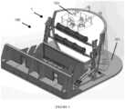
Fig. 1 ,theater seating assembly 1 typically comprises one or moreseat support bases seat support bases passenger seat assembly 260 operatively connected to first passenger seat beam rotator 240a and to second passengerseat beam rotator 240b wherepassenger seat assembly 260 is disposed substantially parallel to the seat axis and comprises a passenger seating area (such ascallout 163 inFig. 2 ); and one or more system controllers 201,202 operatively in communication with firstlift arm actuator 221a, second lift arm actuator 221b, first passenger seatbeam rotator actuator 241a, and second passenger seat beam rotator actuator 241b. - First seat support 200a comprises
first lift arm 220a pivotally connected toseat support base 210a,210b; firstlift arm actuator 221a operatively, and typically pivotally, connected tofirst lift arm 220a and toseat support base 210a,210b, typically pivotally; first passenger seat beam rotator 240a operatively, and typically pivotally, connected tofirst lift arm 220a distally fromseat support base beam rotator actuator 241a operatively connected to first passenger seat beam rotator 240a. First passenger seatbeam rotator actuator 241a is operative to effect a change in passenger seat row pitch independently of rotation offirst lift arm 220a. - Second seat support 200b typically mirrors first seat support 200a and comprises second lift arm 220b which is pivotally connected to
seat support base 210c,210d; second lift arm actuator 221b which is operatively, and typically pivotally, connected to second lift arm 220b and toseat support base 210c, 210d, and typically pivotally, where second lift arm actuator 221b is configured to coordinate movement of second lift arm 220b with movement offirst lift arm 220a; second passengerseat beam rotator 240b which is operatively connected to second lift arm 220b, typically pivotally; and second passenger seat beam rotator actuator 241b which is operatively connected to second passengerseat beam rotator 240b distally from theseat support base 210c,210d. Second passenger seat beam rotator actuator 241b is also operative to effect a change in passenger seat row pitch independently of rotation of second lift arm 220b cooperatively with first passenger seatbeam rotator actuator 241a. - A first X-Y plane is defined by
seat support base 210a, 210b andfirst lift arm 220a and a second X-Y plane is defined byseat support base 210c,210d and second lift arm 220b where the second X-Y plane is substantially parallel to the first X-Y plane. - In this first embodiment,
first lift arm 220a may comprise a lower portion and an upper portion disposed at an angular offset from the lower portion and second lift arm 220b is substantially identical tofirst lift arm 220a. - Typically, in this first embodiment, first passenger seat beam rotator 240a is pivotally connected to
first lift arm 220a at a pivot point located substantially at a center of first passenger seat beam rotator 240a and second passengerseat beam rotator 240b is similarly pivotally connected to second lift arm 220b at a pivot point substantially located at a center of second passengerseat beam rotator 240b. The pivot can be part offirst lift arm 220a or second lift arm 220b and fit into a corresponding void infirst lift arm 220a or second lift arm 220b, respectively, or can be a part offirst lift arm 220a and second lift arm 220b and fit into a corresponding void in first passenger seat beam rotator 240a and second passengerseat beam rotator 240b, respectively. - In this embodiment, passenger seat
beam rotator actuator 241a,241b typically comprises one or more rotary motors which movepassenger seat assembly 260 via passengerseat beam rotators 240a,240b to directly impart pitch toseat beams 260a,260b relative topitch rotators 240a,240b so that pitching the upper row, e.g. 260a, causes the front row, e.g. 260b, to synchronously pitch. Where rotary motors are used,pitch rotators 240a,240b may further comprise a chain or sprocket set 242a,242b. In certain contemplated embodiments, eachrow 260a,260b may be pitched by its own pair of motors, obviating the mechanical interconnection. - System controller 201,202 is operative to control and coordinate movement of
first lift arm 220a and second lift arm 220b in their respective X-Y planes while simultaneously effecting a change to a pitch angle ofpassenger seat assembly 260. - In contemplated versions of this embodiment,
passenger seat assembly 260 typically comprises one ormore seat beams 260a operatively connected to first passenger seat beam rotator 240a at a first end of first passenger seat beam rotator 240a and to second passengerseat beam rotator 240b at a corresponding first end of second passengerseat beam rotator 240b substantially parallel to the seat axis and one or more seat beams 260b operatively connected to first passenger seat beam rotator 240a at a second end of first passenger seat beam rotator 240a distally from the first end and to second passengerseat beam rotator 240b at a corresponding second end of second passengerseat beam rotator 240b substantially parallel to thefirst seat beam 260a. In addition,passenger seat assembly 260 further typically comprises one or more passenger seats 163 (Fig. 2 ) connected to eachseat beam 260a,260b. Further,passenger seat assembly 260 may further comprise canopy (not shown in the figures) and/or shield (not shown in the figures). - In some configurations of this embodiment, one or
more safety encoders 280 may be present and operatively in communication with system controller 201,202 wheresafety encoder 280 is operative to provide a measurement of an offset of first passenger seat beam rotator 240a or second passenger seat beam rotator 240a from the seat axis. Typically, one ormore safety encoders 280 are disposed at predetermined locations, typically at or near joints ofseat beam rotator 240a,240b. - Further, in this embodiment one or more sensors 281,282 may be present and operatively in communication with system controller 201,202 where sensors 281,282 are operative to provide a measurement of a predetermined physical characteristic of
first lift arm 220a or second lift arm 220b such aspressure transducer 281,linear transducer 282, or the like, or a combination thereof. Typically, sensors 281,282 are used to monitor and report lift arm positions to help ensure that they are in sync with each other. - Where
motors 241a,242b and/or 221a,221b are used, each may besafety encoders 280 and/or sensors 281,282 may be used to help monitor the rotation output of an associatedmotor 241a,242b and/or 221a,221b. - In contemplated versions of this embodiment, one or more brakes (not shown in the figures) may be present and operatively connected to
first lift arm 220a or second lift arm 220b, where the brake is operative to impede motion offirst lift arm 220a and/or second lift arm 220b. Brakes may impart braking action to a motor, a shaft rotated or translated by a motor, or a disk or other feature designed to receive such action. In other embodiments, braking may more-or-less passive and be accomplished by the normal state of electrical motors with power removed, or the physical characteristics of hydraulic properties when under pressure. - In contemplated versions of this embodiment, one or
more motion dampers 221a, 221b may be present and operatively connected toseat support base first lift arm 220a, and/or second lift arm 220b.Motion dampers 221c, 221d typically comprise first motion damper 221c operatively connected tofirst lift arm 220a andsecond motion damper 221d operatively connected to second lift arm 220b. - In contemplated versions of this embodiment,
seat support base seat support base seat support base 210a,210b connected tofirst lift arm 220a and secondseat support base 210c,210d connected to second lift arm 220b. Ifmotion dampers 221c, 221d are present,seat support base seat support base 210b connected tofirst lift arm 220a; thirdseat support base 210c connected tosecond motion damper 221d; and fourth seat support base 210d connected to second lift arm 220b. - Referring now to
Fig. 2 , in a further embodiment,seat support base 110 comprisesfirst edge 110a andsecond edge 110b disposed oppositefirst edge 110a. In this embodiment, first seat support 200a (Fig. 1 ) comprisesfirst lift arm 120a pivotally connected tofirst edge 110a at first lift arm seatsupport base end 121a and second seat support 200b comprisessecond lift arm 120b pivotally connected tosecond edge 110b at second lift arm seat support base end 121c. In this embodiment, firstlift arm actuator 130a is operatively connected toseat support base 110, such as atfirst edge 110a, and operative to effect movement offirst lift arm 120a in a first X-Y plane defined byseat support base 110 andfirst lift arm 120a. Second seat support 200b comprises secondlift arm actuator 130b operatively connected toseat support base 110 and operative to cooperatively effect substantially identical movement ofsecond lift arm 120b in a second X-Y plane defined byseat support base 110 andsecond lift arm 120b to the movement offirst lift arm 120a in the first X-Y plane, the second X-Y plane substantially parallel to the first X-Y plane;passenger seat assembly 160 movably disposed intermediatefirst lift arm 120a at attachment arm end 121b disposed opposite first lift arm seatsupport base end 121a and tosecond lift arm 120b atattachment arm end 121d disposed opposite second lift arm seat support base end 121c, thepassenger seat assembly 160 defining a passenger seat row axis disposed longitudinally betweenfirst lift arm 120a andsecond lift arm 120b; and first passenger seat beam rotator 140a and secondpassenger seat rotator 140b which are operative to change a pitch angle ofpassenger seat assembly 160 about the passenger seat row axis. In this embodiment,first edge 110a may extend at an angle fromseat support base 110 andsecond edge 110b may also extend at an angle fromseat support base 110. - In this embodiment, movement of
first lift arm 120a is limited to movement within the first X-Y plane and movement ofsecond lift arm 120b is limited to movement within the second X-Y plane. - In this embodiment, arm actuator 130 comprises first
lift arm actuator 130a which is pivotally connected tofirst lift arm 120a and further pivotally connected tofirst edge 110a and secondlift arm actuator 130b which is pivotally connected tosecond lift arm 120b and further pivotally connected tosecond edge 110b. In this embodiment, firstlift arm actuator 130a typically comprises a plurality of arm actuators, each pivotally connected tofirst edge 110a and tofirst lift arm 120a, and secondlift arm actuator 130a further comprises a plurality of arm actuators, each pivotally connected to second seatsupport base edge 110b and tosecond lift arm 120b. - In this embodiment, first passenger seat beam rotator actuator 140a is pivotally connected to
seat support base 110 proximate the first lift arm seatsupport base end 121a and further comprisespitch link 145, lower crank 142 pivotally connected to first passenger seat row rotator 140a at a first lower crank end and pivotally connected to pitch link 145 at second lower crank end, and upper crank 143 pivotally connected to attachment arm end 121b at a first upper crank end and pivotally connected to pitch link 145 at a second upper crank end. Further, second passenger seatbeam rotator actuator 140b is generally identical to first passenger seat beam rotator actuator 140a and pivotally connected to theseat support base 110 proximate second lift arm seat support base end 121b. First passenger seat pitch actuator 140a and the plurality of arm actuators 130, if present, are operative to cooperatively effect changes to the pitch angle ofpassenger seat assembly 160 an maintain the same pitch angle ofpassenger seat assembly 160 atfirst lift arm 120a relative toseat support base 110 with respect to the pitch angle ofpassenger seat assembly 160 atsecond lift arm 120b relative toseat support base 110. - Moreover, in this embodiment passenger
seat row rotator 150 further comprises one or more passenger seat row rotator pitch cranks 152 pivotally connected to at least one offirst lift arm 120a andsecond lift arm 120b proximate attachment arm ends 121b, 121d of its respective arm and to passenger seat row rotator actuator 151 pivotally connected to at least one offirst lift arm 120a andsecond lift arm 120b at a first end of passenger seat row rotator actuator 151 and pivotally connected to passenger seat row rotator pitch crank 152 at a second end of passenger seat row rotator actuator 151. - In this embodiment,
passenger seat assembly 160 is similar to that which was described above and further comprises one ormore seat beams 161 and at least onepassenger seat 162 connected toseat beam 161. In this embodiment, however,passenger seat assembly 160 further comprises firstseat beam hanger 600 pivotally connected tofirst lift arm 120a proximate first lift arm attachment end 121b at an upper seatbeam hanger end 601 and to an end ofseat beam 161 closest tofirst lift arm 120a as well as secondseat beam hanger 600 pivotally connected tosecond lift arm 120b proximate second liftarm attachment end 121d at an upper seatbeam hanger end 601 and to an end ofseat beam 161 closest tosecond lift arm 120b. Wherepassenger seat assembly 160 comprises twoseat beams 161, eachseat beam hanger 600 of theseat beam hangers 600 typically further comprises upper seat beam hanger crank 602 pivotally connected to armattachment end 121b, 121d of its respective arm; lower seat beam hanger crank 604; and seatbeam hanger link 605 pivotally connected at a first seat beam hanger link end to the upper seat beam hanger crank and pivotally connected at a second seat beam hanger link end to the lower seat beam hanger crank, where the upper seat beam hanger crank and the lower seat beam hanger crank are operative to maintain substantially identical rotation of eachseat beam 161 with respect to each other about their respective passenger seat row axis. - In this embodiment,
theater system 1 may further comprise first liftarm travel limiter 131 disposed onfirst edge 110a proximate where arm actuator 130 is operatively connected to first edge 141, where first liftarm travel limiter 131 is configured to stop movement offirst lift arm 120a in the first X-Y plane. A similar liftarm travel limiter 131 may be present and disposed onsecond edge 110b for limiting movement ofsecond lift arm 120b. - Referring additionally to
Fig. 3 andFig. 4 , in a similar embodiment each of first passenger seat beam rotator 140a (Fig. 2 ) and secondpassenger seat rotator 140b (Fig. 2 ) may compriserotator arm 32 androtator arm limiter 32e configured limit angular travel ofrotator arm 32 about its rotator arm actuator joint 32c in a plane defined bylift arm rotator arm limiter 32e comprises a channel or feature of the joint, such that over-rotation is mechanically prevented by a surface on the rotator arm coming into contact with an opposing surface on lift arm 140, near the pivotal joint by which they are connected. Alternatively, the limiter comprises a feature within the actuator, such as a mechanical hard stop at ends of travel, or a limit switch or sensor which detects a limit in motion. There is a plan to include physical hard tops as a redundant safety measure. The first method of control will be through programming limits. A limit switch might also be used to trigger the end of travel. - In this further embodiment, referring still to
Figs. 2-4 ,theater system 1 comprises one or more seatsupport base platforms 10; one ormore seat actuators 1;first side lift 20;second side lift 20 substantially identical tofirst side lift 20 but arranged in a mirror orientation with respect to the first side life on seatsupport base platform 10; first seatrow beam hanger 31 pivotally connected to the rotator pitch crank joint 32a at a beam hanger joint 27e; second seatrow beam hanger 31 disposed proximate the upper end of the second side lift's lift arm in a mirror orientation with respect to the first seat row beam hanger; seat row beam 30 disposed intermediate the first seat row beam hanger and the second seat beam hanger and rigidly connected to the first seat row beam hanger and the second seat beam hanger; one ormore passenger seats 162 operatively connected to the seat row beam 30; and system controller operatively in communication with and configured to control a predetermined set of functions of the rotateactuators 40,pitch actuators 28, and liftactuators 22. - In this embodiment,
seat support base 10 may comprise first seat support base 10a connected to thefirst lift arm 20a at the first lift arm seatsupport base end 21a and second seat support base 10b connected to the second lift arm 20b at the second lift arm seat support base end 21c. - First side lift 20, in this embodiment, comprises one or more first lift arms 20a disposed at a first side of seat support base platform 10 where first lift arm 20a comprises first end 21a pivotally connected to seat support base platform 10 and pitch link end 21b distally located from first end 21a; one or more rotator arms 32, pivotally connected to lift arm 20 proximate pitch link end 21b at rotator arm middle joint 32b, rotator arm 32 further comprising upper beam arm joint 32a, lower rotator arm joint 32d, and rotator arm actuator joint 32c disposed intermediate upper rotator arm joint 32a and lower rotator arm joint 32d; one or more rotate actuators 40 pivotally connected to rotator arm 32 at upper rotator arm joint 32a and lower rotator arm joint 32d; one or more upper pitch links 27 comprising upper pitch link crank 27a pivotally connected to upper rotator arm joint 32a, lower pitch link crank 27c pivotally connected to lower rotator arm joint 32d, and pitch link 27d pivotally disposed intermediate upper pitch link crank 27a and lower pitch link crank 27c; lower pitch link 29 pivotally connected to first end 21a of lift arm 20a, lower pitch joint comprising arm joint 29c, lower pitch link joint 29b disposed distally from arm joint 29c, and actuator joint 29a disposed intermediate arm joint 29c and lower pitch link joint 29b; pitch crank 25 comprising first pitch crank end 25a pivotally connected to pitch link end 21b and second pitch crank end 25b; pitch link 24 comprising upper pitch link joint 24a pivotally connected to second pitch crank end 25b and lower pitch link joint 24b pivotally connected to lower pitch link joint 29b; pitch actuator 28 pivotally connected to seat support base platform 10 and pivotally connected to actuator joint 29a; and lift actuator 22 pivotally connected to seat support base platform 10 distally from pitch actuator 28 and pivotally connected to lift arm 20 at lift actuator joint 22a disposed proximate first end 21a of lift arm 20a intermediate seat support base platform 10 and rotator pitch crank 29.
Second side lift 20 is typically substantially identical tofirst side lift 20 and therefore its description and callouts are the same or highly similar.- In this embodiment,
rotator arm 32 may further compriserotator arm limiter 32e configured limit angular travel ofrotator arm 32 about its rotator arm actuator joint 32c in a plane defined by its associatedlift arm 20. Additionally, passenger seat row rotator 50 is operative to effect a change in passenger seat row rotation independently of movement offirst lift arm 20a and second lift arm 20b. - In this embodiment, each of first seat
row beam hanger 31 and second seatrow beam hanger 31 may further comprise a link clevis. - In this embodiment, referring additionally to
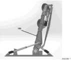
Figs. 7-9 andFigs. 11-12 , rotateactuators 40,pitch actuators 28, and liftactuators 22 are cooperatively operative to control an angular relationship betweenlift arm 20 and its associatedrotator arm 32 by adjusting an angular relationship between the two between a first lift arm lowered position to a second lift arm raised show position. Further, rotateactuators 40,pitch actuators 28, and liftactuators 22 comprise linear actuators configured to motivate thelift arm 20 between a lowered position and a raised position. - In certain configurations of this embodiment, seat
row beam hanger 31 comprises a plurality of seatrow beam hangers 31 and the seat row beam 30 comprises a plurality of seat row beams 30 linearly displaced from each other intermediatefirst end 21a andsecond end 21b oflift arms 20, each seat row beam 30 of the plurality of seat row beams 30 operatively connected to a corresponding set of seatrow beam hangers 31 of the plurality of seatrow beam hangers 31, each seatrow beam hanger 31 of the plurality of seatrow beam hangers 31 linked to at least one other seatrow beam hanger 31 of the plurality of seatrow beam hangers 31 and configured to create synchronous pitch between the plurality of seat row beams 30. - In any of these embodiments, one or more masses may be associated with each lift arm and disposed on a side of the lift arm's seat support base bearing axis as a counterbalance.
- In any of these embodiments, mechanical assistance may be incorporated with lift arm actuators 22,221 so as to reduce energy consumption, e.g. one or more spring assemblies, pneumatic cylinders, or hydraulic cylinders (which communicate with one or more nitrogen-filled vessels) disposed proximate to, and configured to act in association with and for the alleviation of load upon, the lift arm actuators 22,221.
- Referring now to
Figs. 5 and6 ,immersive theater system 100 comprisestheater housing 102;theater seating assembly 1, as described in any of the embodiments above, disposed at least partially withintheater housing 102, and one or moreaudiovisual projectors 103 operatively in communication with system controller 70,201,202 (Fig. 1 ). Typically, seat row beams 161,261 (Fig.1 ,Fig. 2 ) extend outward and throughaisle area 107 on each side oftheater seating assembly 1 into left andright equipment spaces 104 where they then attach to their respective rotators 140,240 (Fig.1 ,Fig. 2 ). As used herein, an audiovisual projector may be a video projector, a combined video-sound system with speakers, or the like, or a combination thereof. - Referring additionally to
Fig. 13 , in certain configurations of this embodiment,immersive theater system 100 comprisesfloor 101 where a portion offloor 101 may be configured to be elevated with respect to one or more seat row beams 161,261 (Fig.1 ,Fig. 2 ) such as to promote shielding of dropped objects from an upper passenger seat to a lower passenger seat. As also noted above, a canopy (not shown in the figures) may be present and fixed over eachpassenger seat 162 which moves with its associatedpassenger seat 162. Additionally,floor 101 may comprise nesting slot orchannel 105 which can accommodate all or a portion of seat row beams 161,261 (Fig.1 ,Fig. 2 ). - In the operation of exemplary methods, as will be understood by one of ordinary skill in theater seating art, reference below to "an" embodiment, unless noted otherwise, is applicable, but not limited to, to other embodiments discussed above.
- Referring back to
Fig. 1 andFigs. 5 -6, a theater experience, typically an immersive theater experience, may be accomplished usingtheater system 1 as described above by positioning first seat support 200a and second seat support 200b and rotatingpassenger seat assembly 260 to a passenger boarding position sufficient to allow a passenger to sit in passenger seat assembly 260 (Fig. 13 ). System controller 70,201,202 substantially synchronously controls first seat support 200a and second seat support 200b and their associated passenger seat beam rotators 240a,240a via their associated seatbeam rotator actuator 241a,241b to effect a motion between eachlift arm 220a,220b and its associatedactuator 221a,221b such as by adjusting the angular relationship between a lift arm lowered position (Fig. 11 ,13 ) to a lift arm raised position (Figs. 7-10 ) at a first predetermined set of times. Rather than pivotingpassenger seat assembly 260 with a rotating floor, positions ofpassenger seat assembly 260 are thus altered while a raising and/or lowering function is taking place. Effecting the pitch change typically occurs at a time from the second predetermined set of times whenfirst lift arm 220a and second lift arm 220b are being raised or lowered. - Typically,
arm actuators 221a,221b are as described above and operative to effect movement infirst lift arm 220a in a first X-Y plane defined byseat support base 210a,210b andfirst lift arm 220a and cooperatively effect substantially identical movement of second lift arm 220b in a second X-Y plane defined byseat support base 210c,210d and second lift arm 220b where the second X-Y plane is substantially parallel to the first X-Y plane. Movement effected by passengerseat beam rotators 240a,240b is operative to change a pitch angle ofpassenger seat 260 about the passenger seat row axis. In most embodiments, system controller 70,201,202 is operatively in communication witharm actuators 221a,221b and passengerseat beam rotators 240a,240b and coordinates movement offirst lift arm 220a and second lift arm 220b in their respective X-Y planes while simultaneously effecting a change to the pitch angle. - In embodiments wherein floor 101 (
Fig. 13 ) further comprises nesting slot or channel 105 (Fig. 13 ) configured to acceptseat row beam 260a,260b therein,seat row beam 260a,260b closest tonesting slot 105 may be nested intonesting slot 105 in a first position, thereby hiding thatseat row beam 260a,260b from audience view while in this lowered load/unload first position. - Referring again to
Fig. 6 ,immersive theater system 100 typically further comprises one or moreaudiovisual projectors 103 as described above and movement of first seat support 200a and second seat support 200b, as well as rotation ofpassenger seat assembly 260, is coordinated withaudiovisual projector 103. Thus, the first predetermined set of times and the second predetermined set of times are typically programmed to coincide with a human perceptive presentation such as from or in coordination with projection fromaudiovisual projector 103. - At times, a surge front to back translation may be provided or imparted while seat supports 200a,220b are in a raised show position by combining the motions of lift and rotate. Further, the pitch function may be used to maintain
passenger seat assembly 260 at a predetermined position with positive and negative pitch available in a raised or show position. - If
passenger seat assembly 260 comprises a plurality of seat beams, e.g.first seat beam 260a and second seat beam 260b as described above, a rotate function may be controlled using system controller 70,201,202 to bring one seat beam ofseat row beams 260a,260b and its associated passenger seats 163 (Fig. 2 ) up and over a second set ofseat row beams 260a,260b and its associatedpassenger seats 163, thereby allowing control over mutual row position during lift and during a show. Additionally, as illustrated inFigs. 7-12 , the rotate function may be used to allowseat row beams 260a,206b and their associatedpassenger seats rows 163 to flatten out, such as from front to back, in order to "hop" over a lower theater screen or wall during lift and achieve a predetermined final vertical relationship once past that hurdle. Also, a second function may be performed, e.g. via command from system controller 70,201,202, to alter mutual positions ofseat row beams 260a and their associatedpassenger seats 163 relative to one another while a lift function is taking place. - In certain of the embodiments discussed above, pitch of individual
seat row beams 260a,260b and their associatedpassenger seats 163 may be controlled in both a forward and a backward motion by forcing rotation of seatrow beam hangers 600 on each seat row beam's ends relative to floor, if seatrow beam hangers 600 are present. - In a further embodiment, referring now generally to
Figs. 7-10 , an immersive theater experience for an immersive theater system may be provided by using the system controller to command the rotateactuators 40,pitch actuators 28, and liftactuators 22 to position the seat actuator to a first position; controlling left and right liftarm rotator arms 32 via their associatedactuators 40 to effect a motion between eachlift arm 20 and its associatedrotator arm 32 to adjust an angular relationship between the two by adjusting the angular relationship between a first lift arm lowered position to a second lift arm raised show position (Figs. 7-10 ); and, rather than pivoting seat row beams 161 and their associatedpassenger seats 162 with a rotating floor, altering mutual positions of seat row beams 161 and their associatedpassenger seats 162 relative to one another while a lift function is taking place with respect to liftarms 20 such that a rotate function brings a second set of seat row beams 161 of seat row beams 161 and its associatedpassenger seats 162 up and over a second set of seat row beams 161 and its associatedpassenger seats 162, thereby allowing control over mutual row position during lift and during a show. The rotate function provided byrotator arms 32 may be used to allow the sets of seat row beams 161 and their associatedpassenger seats 162 to flatten out, front to back, in order to "hop" over a lower theater screen or wall during lift and achieve a predetermined final vertical relationship once past that hurdle. - In addition, a second function may be performed to alter mutual positions of the sets of the seat row beams 161 and their associated
passenger seats 162 relative to one another while the lift function is taking place. - As with other methods, where floor 101 (
Fig. 13 ) further comprisesnesting slot 105 configured to acceptseat row beam 161,seat row beam 161 may be nested or otherwise received intonesting slot 105 in a first position, thereby hidingseat row beam 161 from audience view while in a lowered load/unload first position. - In addition, pitch of individual seat row beams 161 and their associated
passenger seats 162 may be controlled, typically in both forward and backward directions, by forcing rotation of seatrow beam hangers 31 on each seat row beam's ends relative tofacility floor 101. This is typically accomplished using system controller 70,201,202 and may be further in conjunction withprojectors 103 such as during a show. - Other functions may be controlled as well. By way of example and not limitation, a surge front to back translation may be imparted while
lift arms 20 are in a raised show position by combining the motions of lift and rotate. By way of further example and not limitation, the pitch function be used to maintainpassenger seats 162 at a predetermined position with positive and negative pitch available in the raised show position. - As described herein, in embodiments the first and second lift arms, e.g. 20, have a pivotal joint with a passenger seat beam rotator which is controlled by one or more, preferably linear, actuators or rotary motors. The action of these actuators/motors is between the arms and their associated passenger seat beam rotator, adjusting the angular relationship between the two.
- Though no cables are involved, the theater seating assembly described herein still employs seating that is suspended, by way of the seat beams to which each passenger seat is attached. In embodiments, as also described herein, the theater seating assembly can provide controlled pitch of individual seat rows, both forward and backward, such as by forcing rotation of the hangers on each seat row beam's ends. This rotation is relative to the facility floor, and not the lift arm or rotator. Most embodiments are agnostic of seating type placed upon its beams. For example, it can support individual or banks of motion-seat support base seats or rows of static seats having no further motion.
- The foregoing disclosure and description of the inventions are illustrative and explanatory. Various changes in the size, shape, and materials, as well as in the details of the illustrative construction and/or an illustrative method may be made without departing from the scope of the appended claims.
Claims (15)
- A theater seating assembly (2), comprising:a. a seat support base (210a, 210b, 210c, 210d);b. a first seat support (200a), comprising:i. a first lift arm (220a) pivotally connected to the seat support base (210a, 210b), the first lift arm (220a) comprising:1. a lower portion; and2. an upper portion disposed at an angular offset from the lower portion;ii. a first lift arm actuator (221a) operatively connected to the first lift arm (220a);iii. a first passenger seat beam rotator (240a) operatively connected to the first lift arm (220a) distally from the seat support base (210a, 210b, 210c, 210d); andiv. a first passenger seat beam rotator actuator (241a) operatively connected to the first passenger seat beam rotator (240a), the first passenger seat beam rotator actuator (241a) operative to effect a change in passenger seat row pitch independently of rotation of the first lift arm (220a);c. a second seat support (200b) disposed distally from the first seat support (200a) in a mirror configuration with respect to a seat axis defined by a longitudinal distance between the first seat support (200a) and the second seat support (200b), comprising:i. a second lift arm (220b) pivotally connected to the seat support base (210a, 210b, 210c, 210d), the second lift arm (220a) comprising:1. a lower portion; and2. an upper portion disposed at an angular offset from the lower portion;ii. a second lift arm actuator (221b) operatively connected to the second lift arm (220b) and configured to coordinate movement of the second lift arm with the first lift arm;iii. a second passenger seat beam rotator (240b) operatively connected to the second lift arm (220b); andiv. a second passenger seat beam rotator actuator (241b) operatively connected to the second passenger seat beam rotator (240b) distally from the seat support base (210a, 210b, 210c, 210d), the second passenger seat beam rotator actuator (241b) operative to effect a change in passenger seat row pitch independently of rotation of the second lift arm (220b) cooperatively with the first passenger seat beam rotator actuator (241a);d. a passenger seat assembly (260) operatively connected to the first passenger seat beam rotator (240a) and to the second passenger seat beam rotator (240b), the passenger seat assembly (260) disposed substantially parallel to the seat axis, the passenger seat assembly comprising a passenger seating area (162); ande. a system controller (201, 202) operatively in communication with the first lift arm actuator (221a), the second lift arm actuator (221b), the first passenger seat beam rotator actuator (241a), and the second passenger seat beam rotator actuator (241b), the system controller operative to coordinate movement of the first lift arm with the second lift arm in their respective X-Y planes while simultaneously effecting a change to the pitch angle and to coordinate movement of the first passenger seat beam rotator actuator (241a) with the second passenger seat beam rotator actuator (241b).
- The theater seating assembly of Claim 1, wherein the seat support base (210a, 210b, 210c, 210d) comprises a first seat support base (210a, 210b) connected to the first lift arm (220a) and a second seat support base (210c, 210d) connected to the second lift arm (220b).
- The theater seating assembly of Claim 1, further comprising a safety encoder (280) operatively in communication with the system controller (201, 202), the safety encoder operative to provide a measurement of an offset of the first passenger seat beam rotator (240a) or the second passenger seat beam rotator (240a) from the seat axis.
- The theater seating assembly of Claim 1, further comprising a sensor (281, 282) operatively in communication with the system controller (201, 202), the sensor operative to provide a measurement of a predetermined physical characteristic of the first lift arm (220a) or the second (220b); and, optionally,
wherein the sensor (281, 282) comprises a pressure transducer (281) or a linear transducer (282). - The theater seating assembly of Claim 1, wherein each lift arm actuator (221a, 221b) further comprises a motion damper (221c, 221d) operatively connected to the seat support base (210a, 210b, 210c, 210d) and the first lift arm (220a) or the second lift arm (220b).
- The theater seating assembly of Claim 5, wherein the motion damper (221c, 221d) comprises:a. a first motion damper (221c) operatively connected to the first lift arm (220a); andb. a second motion damper (221d) operatively connected to the second lift arm (220b).
- The theater seating assembly of Claim 6, wherein the seat support base (210a, 210b, 210c, 210d) comprises:a. a first seat support base (210a) operatively connected to the first motion damper (221c);b. a second seat support base (210b) connected to the first lift arm (220d);c. a third seat support base (210c) connected to the second motion damper (221b); andd. a fourth seat support base (210d) connected to the second lift arm (220b).
- The theater seating assembly of Claim 1, further comprising a brake operatively connected to the first lift arm (220a) or the second lift arm (220b), the brake operative to impede motion of the first lift arm (220a) or the second lift arm (220b).
- The theater seating assembly of Claim 1, wherein:a. the first passenger seat beam rotator (240a) is pivotally connected to the first lift arm (220a) at a pivot substantially located at a center of the first passenger seat beam rotator (240a); andb. the second passenger seat beam rotator (240b) is pivotally connected to the second lift arm (220b) at a pivot substantially located at a center of the second passenger seat beam rotator (240b).
- The theater seating assembly of Claim 1, wherein the passenger seat assembly (260) comprises:a. a first seat beam (260a) operatively connected to the first passenger seat beam rotator (240a) at a first end of the first passenger seat beam rotator (240a) and the second passenger seat beam rotator (240b) at a corresponding first end of the second passenger seat beam rotator (240b) substantially parallel to the seat axis; andb. a second seat beam (260b) operatively connected to the first passenger seat beam rotator (240a) at a second end of the first passenger seat beam rotator (240a) distally from the first end and the second passenger seat beam rotator (240b) at a corresponding second end of the second passenger seat beam rotator (240b) substantially parallel to the first seat beam (260a).
- The theater seating assembly of Claim 1, wherein the passenger seat assembly (260) further comprises:a. a seat beam (260a, 260b); andb. a passenger seating area (162) connected to the seat beam.
- The theater seating assembly of Claim 1, wherein each of the rotator actuators (241a, 241b) comprises:a. a rotary motor; andb. a chain or sprocket set operatively in communication with the rotary motor.
- The theater seating assembly of Claim 1, wherein the passenger seat assembly (160) further comprises a canopy.
- The theater seating assembly of Claim 1, wherein the passenger seat assembly (160) further comprises a shield.
- A method of providing a theater experience using a theater seating assembly comprising a seat support base (210a, 210b, 210c, 210d); a first seat support (200a) comprising a first lift arm (220a) pivotally connected to the seat support base (210a, 210b) where the first lift arm (220a) comprises a lower portion and an upper portion disposed at an angular offset from the lower portion, a first lift arm actuator (221a) operatively connected to the first lift arm (220a), a first passenger seat beam rotator (240a) operatively connected to the first lift arm (220a) distally from the seat support base (210a, 210b, 210c, 210d), and a first passenger seat beam rotator actuator (241a) operatively connected to the first passenger seat beam rotator (240a) where the first passenger seat beam rotator actuator (241a) is operative to effect a change in passenger seat row pitch independently of rotation of the first lift arm (220a); a second seat support (200b) disposed distally from the first seat support (200a) in a mirror configuration with respect to a seat axis defined by a longitudinal distance between the first seat support (200a) and the second seat support (200b), comprising a second lift arm (220b) pivotally connected to the seat support base (210a, 210b, 210c, 210d) where the second lift arm (220a) comprises a lower portion and an upper portion disposed at an angular offset from the lower portion; and a second lift arm actuator (221b) operatively connected to the second lift arm (220b) and configured to coordinate movement of the second lift arm with the first lift arm; a second passenger seat beam rotator (240b) operatively connected to the second lift arm (220b), and a second passenger seat beam rotator actuator (241b) operatively connected to the second passenger seat beam rotator (240b) distally from the seat support base (210a, 210b, 210c, 210d) where the second passenger seat beam rotator actuator (241b) is operative to effect a change in passenger seat row pitch independently of rotation of the second lift arm (220b) cooperatively with the first passenger seat beam rotator actuator (241a); a passenger seat assembly (260) operatively connected to the first passenger seat beam rotator (240a) and to the second passenger seat beam rotator (240b), the passenger seat assembly (260) disposed substantially parallel to the seat axis, the passenger seat assembly comprising a passenger seating area; and a system controller (201, 202) operatively in communication with the first lift arm actuator (221a), the second lift arm actuator (221b), the first passenger seatbeam rotator actuator (241a), and the second passenger seat beam rotator actuator (241b), the system controller operative to coordinate movement of the first lift arm with the second lift arm in their respective X-Y planes while simultaneously effecting a change to the pitch angle and to coordinate movement of the first passenger seat beam rotator actuator (241a) with the second passenger seat beam rotator actuator (241b), the method comprising:a. positioning the first lift arm and the second lift arm and rotating the passenger seat assembly to a passenger boarding position sufficient to allow a passenger to sit in the passenger seat assembly;b. using the system controller to substantially synchronously control the left and right lift arms and rotator arms via their associated actuators to effect a motion between each lift arm and its associated rotator to adjust an angular relationship between the two by adjusting an angular relationship between a first lift arm lowered position to a second lift arm raised position at a first predetermined set of times; andc. rather than pivoting the passenger seat assembly with a rotating floor, altering positions of the passenger seat assembly while a raising and lowering function is taking place.
Applications Claiming Priority (2)
| Application Number | Priority Date | Filing Date | Title |
|---|---|---|---|
| US201962832763P | 2019-04-11 | 2019-04-11 | |
| PCT/US2020/027765WO2020210699A1 (en) | 2019-04-11 | 2020-04-10 | Suspended theater edge actuated seat moving machine |
Publications (3)
| Publication Number | Publication Date |
|---|---|
| EP3953009A1 EP3953009A1 (en) | 2022-02-16 |
| EP3953009A4 EP3953009A4 (en) | 2022-12-28 |
| EP3953009B1true EP3953009B1 (en) | 2024-06-26 |
Family
ID=72748763
Family Applications (3)
| Application Number | Title | Priority Date | Filing Date |
|---|---|---|---|
| EP20787615.2AActiveEP3953009B1 (en) | 2019-04-11 | 2020-04-10 | Suspended theater edge actuated seat moving machine |
| EP20787837.2AActiveEP3953545B1 (en) | 2019-04-11 | 2020-04-10 | Suspended theater edge actuated seat moving machine |
| EP20787584.0AActiveEP3953544B1 (en) | 2019-04-11 | 2020-04-10 | Suspended theater with edge actuators |
Family Applications After (2)
| Application Number | Title | Priority Date | Filing Date |
|---|---|---|---|
| EP20787837.2AActiveEP3953545B1 (en) | 2019-04-11 | 2020-04-10 | Suspended theater edge actuated seat moving machine |
| EP20787584.0AActiveEP3953544B1 (en) | 2019-04-11 | 2020-04-10 | Suspended theater with edge actuators |
Country Status (9)
| Country | Link |
|---|---|
| US (3) | US11058966B2 (en) |
| EP (3) | EP3953009B1 (en) |
| JP (3) | JP7550788B2 (en) |
| KR (3) | KR102762489B1 (en) |
| CN (3) | CN113939351B (en) |
| AU (3) | AU2020272051A1 (en) |
| CA (3) | CA3136669A1 (en) |
| SG (3) | SG11202111224SA (en) |
| WO (3) | WO2020210699A1 (en) |
Families Citing this family (4)
| Publication number | Priority date | Publication date | Assignee | Title |
|---|---|---|---|---|
| WO2020210699A1 (en)* | 2019-04-11 | 2020-10-15 | Oceaneering International, Inc. | Suspended theater edge actuated seat moving machine |
| AT525245B1 (en)* | 2021-09-06 | 2023-02-15 | Attraktion! GmbH | Seat unit for an extended cinematic experience |
| US20230098299A1 (en)* | 2021-09-29 | 2023-03-30 | Dynamic Structures Ltd | Flying theater motion base and related methods |
| CN115025500B (en)* | 2022-04-21 | 2025-05-13 | 江苏博人文化科技有限公司 | A multi-degree-of-freedom riding-type flight experience device based on special effects simulation |
Family Cites Families (46)
| Publication number | Priority date | Publication date | Assignee | Title |
|---|---|---|---|---|
| US1789680A (en)* | 1928-10-01 | 1931-01-20 | James E Gwinnett | Amusement device |
| US3967387A (en)* | 1974-10-21 | 1976-07-06 | Daniel Marchegiani | Motion simulator |
| US4066256A (en)* | 1975-11-17 | 1978-01-03 | Future General Corporation | Amusement ride |
| US5388991A (en)* | 1992-10-20 | 1995-02-14 | Magic Edge, Inc. | Simulation device and system |
| US5558582A (en)* | 1994-10-14 | 1996-09-24 | Enhanced Simulation, Inc. | Rotating motion simulator |
| IT232096Y1 (en)* | 1994-11-29 | 1999-08-16 | Soriani & Moser Manufacturers | CAROUSEL OF FUN PERFECTED |
| JPH0947580A (en)* | 1995-08-10 | 1997-02-18 | Masamichi Kitou | Play tool |
| JPH10207338A (en)* | 1997-01-20 | 1998-08-07 | Hitachi Ltd | Simulated experience passenger movement device |
| JP3216625B2 (en)* | 1999-01-19 | 2001-10-09 | コクヨ株式会社 | Chair |
| US6533670B1 (en)* | 2000-08-14 | 2003-03-18 | Universal City Studio, Inc. | Amusement ride with pivotable motion base |
| US6354954B1 (en)* | 2000-12-28 | 2002-03-12 | Disney Enterprises, Inc. | Amusement apparatus and method |
| CN1297329C (en)* | 2003-04-15 | 2007-01-31 | 李明 | Action imitation equipment for amusement and its method |
| NL1026349C1 (en)* | 2004-06-07 | 2005-12-08 | Kig Heerenveen Bv | Fairground attraction with a person carrier suspended from two mutually parallel rotatable arms. |
| WO2007057171A2 (en)* | 2005-11-15 | 2007-05-24 | Huss Park Attractions Gmbh | Device for accommodating at least one spectator of an image projection |
| DE102009022567B4 (en)* | 2009-05-25 | 2013-05-23 | Stanzwerk Wetter Sichelschmidt Gmbh & Co. Kg | Seating furniture with stand-up aid |
| CN201492022U (en)* | 2009-07-17 | 2010-06-02 | 梁秀芬 | Dynamic movie theatre chair device |
| CA2678573C (en)* | 2009-09-14 | 2017-09-19 | Simex Inc. | Seat assembly such as for an amusement ride |
| CN201676517U (en)* | 2010-02-08 | 2010-12-22 | 温州南方游乐设备工程有限公司 | Super wave billowing amusement machine |
| US8308228B2 (en)* | 2010-02-11 | 2012-11-13 | L & P Property Management Company | Zero-wall clearance linkage mechanism for a lifting recliner |
| US8225555B2 (en)* | 2010-02-25 | 2012-07-24 | Falcon's Treehouse, L.L.C. | Motion simulator theater with suspended seating |
| CN201775967U (en)* | 2010-08-04 | 2011-03-30 | 诺华特控股有限公司 | Dynamic simulation cinema simulation system |
| CN101912689B (en) | 2010-08-04 | 2012-10-17 | 诺华特控股有限公司 | Dynamic simulation cinema simulation system, method and equipment |
| US9162150B2 (en)* | 2010-09-23 | 2015-10-20 | Vekoma Rides Engineering B.V. | Pivotable passenger carrier |
| CN102535893B (en)* | 2012-01-20 | 2014-02-26 | 万达商业规划研究院有限公司 | A movable stand with variable viewing angle |
| US8721464B2 (en)* | 2012-02-02 | 2014-05-13 | Brogent Technologies Inc. | Biaxial suspension type dynamic simulator |
| CA2793598C (en)* | 2012-10-26 | 2015-10-20 | Dynamic Structures, Ltd. | Flying theatre |
| CN202920999U (en)* | 2012-11-23 | 2013-05-08 | 刘彬 | Five-dimensional (5D) interaction theatre |
| US9536446B2 (en)* | 2012-12-03 | 2017-01-03 | Dynamic Motion Group Gmbh | Motion simulation system controller and associated methods |
| WO2014130459A1 (en)* | 2013-02-19 | 2014-08-28 | Dreamlight Holdings Inc., Formerly Known As A Thousand Miles Llc | Rotating performance stage |
| FR3002778B1 (en) | 2013-03-04 | 2015-04-03 | Sti Serapid Group | ROOM, IN PARTICULAR VERSATILE SPECTACLE ROOM |
| DK2967216T3 (en)* | 2013-03-15 | 2018-05-28 | Oceaneering Int Inc | REVERSE MOVEMENT BASE WITH SUSPENDED SEAT AND ENTERTAINMENT PROCEDURE IMPLEMENTED WITH SUCH AN REVERSED MOVEMENT BASIS |
| CN105074567A (en) | 2013-05-31 | 2015-11-18 | Cjcgv株式会社 | Multi-projection system |
| CN203736837U (en)* | 2013-12-06 | 2014-07-30 | 深圳市一品红文化传播有限公司 | Four-dimensional dynamic movie roller coaster experiencing platform |
| CN203710707U (en)* | 2013-12-06 | 2014-07-16 | 深圳市一品红文化传播有限公司 | Dynamic-movie experiencing platform |
| CN103691134B (en)* | 2013-12-30 | 2015-09-09 | 深圳华侨城文化旅游科技股份有限公司 | A kind of Platform-type kinetic car |
| CN103711335B (en)* | 2013-12-30 | 2016-05-04 | 深圳华侨城文化旅游科技股份有限公司 | A kind of comprehensive dynamic tracking viewing system |
| US9540831B2 (en)* | 2014-07-23 | 2017-01-10 | Rogers Athletic Company, Inc. | Seating system |
| EP3212299B1 (en)* | 2014-10-28 | 2020-05-27 | Oceaneering International, Inc. | Suspended amusement ride system |
| AU2016262623A1 (en)* | 2015-05-14 | 2017-11-09 | VIP Cinema LLC | Dual motion sloped floor recline mechanism for a theater |
| US9523209B2 (en)* | 2015-05-15 | 2016-12-20 | Vision 3 Experiential, Llc | Immersive theater |
| NL2016150B1 (en)* | 2016-01-25 | 2017-07-31 | Kig Heerenveen Bv | Attraction for amusement rides with improved support structure. |
| US9511299B1 (en)* | 2016-03-02 | 2016-12-06 | Brogent Technologies Inc. | Rotary dynamic simulation device and audiovisual apparatus using the same |
| CN206762295U (en)* | 2017-03-29 | 2017-12-19 | 河北智跑游乐设备制造有限公司 | A kind of new flight movie theatre |
| CN107537158B (en)* | 2017-08-28 | 2020-01-21 | 上海恒润文化科技有限公司 | Rotary interactive shooting system |
| US10366625B1 (en)* | 2018-01-17 | 2019-07-30 | Brogent Technologies Inc. | Kinesthetic device that simulates flight |
| WO2020210699A1 (en)* | 2019-04-11 | 2020-10-15 | Oceaneering International, Inc. | Suspended theater edge actuated seat moving machine |
- 2020
- 2020-04-10WOPCT/US2020/027765patent/WO2020210699A1/ennot_activeCeased
- 2020-04-10AUAU2020272051Apatent/AU2020272051A1/enactivePending
- 2020-04-10SGSG11202111224SApatent/SG11202111224SA/enunknown
- 2020-04-10KRKR1020217036667Apatent/KR102762489B1/enactiveActive
- 2020-04-10EPEP20787615.2Apatent/EP3953009B1/enactiveActive
- 2020-04-10AUAU2020272050Apatent/AU2020272050B2/enactiveActive
- 2020-04-10CNCN202080042508.1Apatent/CN113939351B/enactiveActive
- 2020-04-10WOPCT/US2020/027769patent/WO2020210702A1/ennot_activeCeased
- 2020-04-10JPJP2021559898Apatent/JP7550788B2/enactiveActive
- 2020-04-10JPJP2021559785Apatent/JP7525508B2/enactiveActive
- 2020-04-10JPJP2021559861Apatent/JP7629864B2/enactiveActive
- 2020-04-10AUAU2020271548Apatent/AU2020271548B2/enactiveActive
- 2020-04-10CACA3136669Apatent/CA3136669A1/enactivePending
- 2020-04-10SGSG11202111226RApatent/SG11202111226RA/enunknown
- 2020-04-10USUS16/846,044patent/US11058966B2/enactiveActive
- 2020-04-10USUS16/846,022patent/US11571632B2/enactiveActive
- 2020-04-10KRKR1020217036666Apatent/KR102762485B1/enactiveActive
- 2020-04-10CACA3136555Apatent/CA3136555A1/enactivePending
- 2020-04-10KRKR1020217036668Apatent/KR102762493B1/enactiveActive
- 2020-04-10CNCN202080042500.5Apatent/CN114008281B/enactiveActive
- 2020-04-10SGSG11202111223UApatent/SG11202111223UA/enunknown
- 2020-04-10CNCN202080042307.1Apatent/CN113950560B/enactiveActive
- 2020-04-10WOPCT/US2020/027761patent/WO2020210696A1/ennot_activeCeased
- 2020-04-10USUS16/846,035patent/US11058965B2/enactiveActive
- 2020-04-10EPEP20787837.2Apatent/EP3953545B1/enactiveActive
- 2020-04-10CACA3136667Apatent/CA3136667A1/enactivePending
- 2020-04-10EPEP20787584.0Apatent/EP3953544B1/enactiveActive
Also Published As
Similar Documents
| Publication | Publication Date | Title |
|---|---|---|
| EP3953009B1 (en) | Suspended theater edge actuated seat moving machine | |
| EP3453668B1 (en) | Suspended theatre ride system | |
| HK40004657A (en) | Suspended theater ride system | |
| HK40004657B (en) | Suspended theater ride system |
Legal Events
| Date | Code | Title | Description |
|---|---|---|---|
| STAA | Information on the status of an ep patent application or granted ep patent | Free format text:STATUS: THE INTERNATIONAL PUBLICATION HAS BEEN MADE | |
| PUAI | Public reference made under article 153(3) epc to a published international application that has entered the european phase | Free format text:ORIGINAL CODE: 0009012 | |
| STAA | Information on the status of an ep patent application or granted ep patent | Free format text:STATUS: REQUEST FOR EXAMINATION WAS MADE | |
| 17P | Request for examination filed | Effective date:20210924 | |
| AK | Designated contracting states | Kind code of ref document:A1 Designated state(s):AL AT BE BG CH CY CZ DE DK EE ES FI FR GB GR HR HU IE IS IT LI LT LU LV MC MK MT NL NO PL PT RO RS SE SI SK SM TR | |
| DAV | Request for validation of the european patent (deleted) | ||
| DAX | Request for extension of the european patent (deleted) | ||
| REG | Reference to a national code | Ref country code:DE Ref legal event code:R079 Free format text:PREVIOUS MAIN CLASS: A63G0009080000 Ipc:A47C0001120000 Ref document number:602020033056 Country of ref document:DE | |
| A4 | Supplementary search report drawn up and despatched | Effective date:20221125 | |
| RIC1 | Information provided on ipc code assigned before grant | Ipc:E04H 3/30 20060101ALI20221121BHEP Ipc:A63J 5/00 20060101ALI20221121BHEP Ipc:A63J 25/00 20090101ALI20221121BHEP Ipc:A63G 27/02 20060101ALI20221121BHEP Ipc:A47C 1/12 20060101AFI20221121BHEP | |
| P01 | Opt-out of the competence of the unified patent court (upc) registered | Effective date:20230526 | |
| GRAP | Despatch of communication of intention to grant a patent | Free format text:ORIGINAL CODE: EPIDOSNIGR1 | |
| STAA | Information on the status of an ep patent application or granted ep patent | Free format text:STATUS: GRANT OF PATENT IS INTENDED | |
| INTG | Intention to grant announced | Effective date:20231109 | |
| GRAS | Grant fee paid | Free format text:ORIGINAL CODE: EPIDOSNIGR3 | |
| GRAA | (expected) grant | Free format text:ORIGINAL CODE: 0009210 | |
| STAA | Information on the status of an ep patent application or granted ep patent | Free format text:STATUS: THE PATENT HAS BEEN GRANTED | |
| RAP3 | Party data changed (applicant data changed or rights of an application transferred) | Owner name:OCEANEERING INTERNATIONAL, INC. | |
| AK | Designated contracting states | Kind code of ref document:B1 Designated state(s):AL AT BE BG CH CY CZ DE DK EE ES FI FR GB GR HR HU IE IS IT LI LT LU LV MC MK MT NL NO PL PT RO RS SE SI SK SM TR | |
| REG | Reference to a national code | Ref country code:GB Ref legal event code:FG4D | |
| REG | Reference to a national code | Ref country code:CH Ref legal event code:EP | |
| REG | Reference to a national code | Ref country code:DE Ref legal event code:R096 Ref document number:602020033056 Country of ref document:DE | |
| REG | Reference to a national code | Ref country code:NL Ref legal event code:FP | |
| PG25 | Lapsed in a contracting state [announced via postgrant information from national office to epo] | Ref country code:BG Free format text:LAPSE BECAUSE OF FAILURE TO SUBMIT A TRANSLATION OF THE DESCRIPTION OR TO PAY THE FEE WITHIN THE PRESCRIBED TIME-LIMIT Effective date:20240626 | |
| PG25 | Lapsed in a contracting state [announced via postgrant information from national office to epo] | Ref country code:FI Free format text:LAPSE BECAUSE OF FAILURE TO SUBMIT A TRANSLATION OF THE DESCRIPTION OR TO PAY THE FEE WITHIN THE PRESCRIBED TIME-LIMIT Effective date:20240626 Ref country code:HR Free format text:LAPSE BECAUSE OF FAILURE TO SUBMIT A TRANSLATION OF THE DESCRIPTION OR TO PAY THE FEE WITHIN THE PRESCRIBED TIME-LIMIT Effective date:20240626 | |
| REG | Reference to a national code | Ref country code:LT Ref legal event code:MG9D | |
| PG25 | Lapsed in a contracting state [announced via postgrant information from national office to epo] | Ref country code:GR Free format text:LAPSE BECAUSE OF FAILURE TO SUBMIT A TRANSLATION OF THE DESCRIPTION OR TO PAY THE FEE WITHIN THE PRESCRIBED TIME-LIMIT Effective date:20240927 | |
| PG25 | Lapsed in a contracting state [announced via postgrant information from national office to epo] | Ref country code:LV Free format text:LAPSE BECAUSE OF FAILURE TO SUBMIT A TRANSLATION OF THE DESCRIPTION OR TO PAY THE FEE WITHIN THE PRESCRIBED TIME-LIMIT Effective date:20240626 | |
| PG25 | Lapsed in a contracting state [announced via postgrant information from national office to epo] | Ref country code:LV Free format text:LAPSE BECAUSE OF FAILURE TO SUBMIT A TRANSLATION OF THE DESCRIPTION OR TO PAY THE FEE WITHIN THE PRESCRIBED TIME-LIMIT Effective date:20240626 Ref country code:HR Free format text:LAPSE BECAUSE OF FAILURE TO SUBMIT A TRANSLATION OF THE DESCRIPTION OR TO PAY THE FEE WITHIN THE PRESCRIBED TIME-LIMIT Effective date:20240626 Ref country code:GR Free format text:LAPSE BECAUSE OF FAILURE TO SUBMIT A TRANSLATION OF THE DESCRIPTION OR TO PAY THE FEE WITHIN THE PRESCRIBED TIME-LIMIT Effective date:20240927 Ref country code:FI Free format text:LAPSE BECAUSE OF FAILURE TO SUBMIT A TRANSLATION OF THE DESCRIPTION OR TO PAY THE FEE WITHIN THE PRESCRIBED TIME-LIMIT Effective date:20240626 Ref country code:BG Free format text:LAPSE BECAUSE OF FAILURE TO SUBMIT A TRANSLATION OF THE DESCRIPTION OR TO PAY THE FEE WITHIN THE PRESCRIBED TIME-LIMIT Effective date:20240626 Ref country code:RS Free format text:LAPSE BECAUSE OF FAILURE TO SUBMIT A TRANSLATION OF THE DESCRIPTION OR TO PAY THE FEE WITHIN THE PRESCRIBED TIME-LIMIT Effective date:20240926 | |
| REG | Reference to a national code | Ref country code:AT Ref legal event code:MK05 Ref document number:1696939 Country of ref document:AT Kind code of ref document:T Effective date:20240626 | |
| PG25 | Lapsed in a contracting state [announced via postgrant information from national office to epo] | Ref country code:PT Free format text:LAPSE BECAUSE OF FAILURE TO SUBMIT A TRANSLATION OF THE DESCRIPTION OR TO PAY THE FEE WITHIN THE PRESCRIBED TIME-LIMIT Effective date:20241028 | |
| PG25 | Lapsed in a contracting state [announced via postgrant information from national office to epo] | Ref country code:PT Free format text:LAPSE BECAUSE OF FAILURE TO SUBMIT A TRANSLATION OF THE DESCRIPTION OR TO PAY THE FEE WITHIN THE PRESCRIBED TIME-LIMIT Effective date:20241028 | |
| PG25 | Lapsed in a contracting state [announced via postgrant information from national office to epo] | Ref country code:PL Free format text:LAPSE BECAUSE OF FAILURE TO SUBMIT A TRANSLATION OF THE DESCRIPTION OR TO PAY THE FEE WITHIN THE PRESCRIBED TIME-LIMIT Effective date:20240626 | |
| PG25 | Lapsed in a contracting state [announced via postgrant information from national office to epo] | Ref country code:EE Free format text:LAPSE BECAUSE OF FAILURE TO SUBMIT A TRANSLATION OF THE DESCRIPTION OR TO PAY THE FEE WITHIN THE PRESCRIBED TIME-LIMIT Effective date:20240626 | |
| PG25 | Lapsed in a contracting state [announced via postgrant information from national office to epo] | Ref country code:AT Free format text:LAPSE BECAUSE OF FAILURE TO SUBMIT A TRANSLATION OF THE DESCRIPTION OR TO PAY THE FEE WITHIN THE PRESCRIBED TIME-LIMIT Effective date:20240626 Ref country code:IS Free format text:LAPSE BECAUSE OF FAILURE TO SUBMIT A TRANSLATION OF THE DESCRIPTION OR TO PAY THE FEE WITHIN THE PRESCRIBED TIME-LIMIT Effective date:20241026 | |
| PG25 | Lapsed in a contracting state [announced via postgrant information from national office to epo] | Ref country code:CZ Free format text:LAPSE BECAUSE OF FAILURE TO SUBMIT A TRANSLATION OF THE DESCRIPTION OR TO PAY THE FEE WITHIN THE PRESCRIBED TIME-LIMIT Effective date:20240626 | |
| PG25 | Lapsed in a contracting state [announced via postgrant information from national office to epo] | Ref country code:RO Free format text:LAPSE BECAUSE OF FAILURE TO SUBMIT A TRANSLATION OF THE DESCRIPTION OR TO PAY THE FEE WITHIN THE PRESCRIBED TIME-LIMIT Effective date:20240626 Ref country code:SK Free format text:LAPSE BECAUSE OF FAILURE TO SUBMIT A TRANSLATION OF THE DESCRIPTION OR TO PAY THE FEE WITHIN THE PRESCRIBED TIME-LIMIT Effective date:20240626 | |
| PG25 | Lapsed in a contracting state [announced via postgrant information from national office to epo] | Ref country code:SM Free format text:LAPSE BECAUSE OF FAILURE TO SUBMIT A TRANSLATION OF THE DESCRIPTION OR TO PAY THE FEE WITHIN THE PRESCRIBED TIME-LIMIT Effective date:20240626 Ref country code:ES Free format text:LAPSE BECAUSE OF FAILURE TO SUBMIT A TRANSLATION OF THE DESCRIPTION OR TO PAY THE FEE WITHIN THE PRESCRIBED TIME-LIMIT Effective date:20240626 | |
| PG25 | Lapsed in a contracting state [announced via postgrant information from national office to epo] | Ref country code:SM Free format text:LAPSE BECAUSE OF FAILURE TO SUBMIT A TRANSLATION OF THE DESCRIPTION OR TO PAY THE FEE WITHIN THE PRESCRIBED TIME-LIMIT Effective date:20240626 Ref country code:SK Free format text:LAPSE BECAUSE OF FAILURE TO SUBMIT A TRANSLATION OF THE DESCRIPTION OR TO PAY THE FEE WITHIN THE PRESCRIBED TIME-LIMIT Effective date:20240626 Ref country code:RO Free format text:LAPSE BECAUSE OF FAILURE TO SUBMIT A TRANSLATION OF THE DESCRIPTION OR TO PAY THE FEE WITHIN THE PRESCRIBED TIME-LIMIT Effective date:20240626 Ref country code:PL Free format text:LAPSE BECAUSE OF FAILURE TO SUBMIT A TRANSLATION OF THE DESCRIPTION OR TO PAY THE FEE WITHIN THE PRESCRIBED TIME-LIMIT Effective date:20240626 Ref country code:IS Free format text:LAPSE BECAUSE OF FAILURE TO SUBMIT A TRANSLATION OF THE DESCRIPTION OR TO PAY THE FEE WITHIN THE PRESCRIBED TIME-LIMIT Effective date:20241026 Ref country code:ES Free format text:LAPSE BECAUSE OF FAILURE TO SUBMIT A TRANSLATION OF THE DESCRIPTION OR TO PAY THE FEE WITHIN THE PRESCRIBED TIME-LIMIT Effective date:20240626 Ref country code:EE Free format text:LAPSE BECAUSE OF FAILURE TO SUBMIT A TRANSLATION OF THE DESCRIPTION OR TO PAY THE FEE WITHIN THE PRESCRIBED TIME-LIMIT Effective date:20240626 Ref country code:CZ Free format text:LAPSE BECAUSE OF FAILURE TO SUBMIT A TRANSLATION OF THE DESCRIPTION OR TO PAY THE FEE WITHIN THE PRESCRIBED TIME-LIMIT Effective date:20240626 Ref country code:AT Free format text:LAPSE BECAUSE OF FAILURE TO SUBMIT A TRANSLATION OF THE DESCRIPTION OR TO PAY THE FEE WITHIN THE PRESCRIBED TIME-LIMIT Effective date:20240626 | |
| PG25 | Lapsed in a contracting state [announced via postgrant information from national office to epo] | Ref country code:IT Free format text:LAPSE BECAUSE OF FAILURE TO SUBMIT A TRANSLATION OF THE DESCRIPTION OR TO PAY THE FEE WITHIN THE PRESCRIBED TIME-LIMIT Effective date:20240626 | |
| REG | Reference to a national code | Ref country code:DE Ref legal event code:R097 Ref document number:602020033056 Country of ref document:DE | |
| PG25 | Lapsed in a contracting state [announced via postgrant information from national office to epo] | Ref country code:DK Free format text:LAPSE BECAUSE OF FAILURE TO SUBMIT A TRANSLATION OF THE DESCRIPTION OR TO PAY THE FEE WITHIN THE PRESCRIBED TIME-LIMIT Effective date:20240626 | |
| PLBE | No opposition filed within time limit | Free format text:ORIGINAL CODE: 0009261 | |
| STAA | Information on the status of an ep patent application or granted ep patent | Free format text:STATUS: NO OPPOSITION FILED WITHIN TIME LIMIT | |
| 26N | No opposition filed | Effective date:20250327 | |
| PGFP | Annual fee paid to national office [announced via postgrant information from national office to epo] | Ref country code:NL Payment date:20250526 Year of fee payment:6 | |
| PGFP | Annual fee paid to national office [announced via postgrant information from national office to epo] | Ref country code:DE Payment date:20250521 Year of fee payment:6 | |
| PGFP | Annual fee paid to national office [announced via postgrant information from national office to epo] | Ref country code:GB Payment date:20250522 Year of fee payment:6 | |
| PGFP | Annual fee paid to national office [announced via postgrant information from national office to epo] | Ref country code:NO Payment date:20250528 Year of fee payment:6 | |
| PGFP | Annual fee paid to national office [announced via postgrant information from national office to epo] | Ref country code:FR Payment date:20250530 Year of fee payment:6 | |
| PG25 | Lapsed in a contracting state [announced via postgrant information from national office to epo] | Ref country code:SE Free format text:LAPSE BECAUSE OF FAILURE TO SUBMIT A TRANSLATION OF THE DESCRIPTION OR TO PAY THE FEE WITHIN THE PRESCRIBED TIME-LIMIT Effective date:20240626 |