EP3949903B1 - System for crimping a prosthetic valve - Google Patents
System for crimping a prosthetic valveDownload PDFInfo
- Publication number
- EP3949903B1 EP3949903B1EP21152339.4AEP21152339AEP3949903B1EP 3949903 B1EP3949903 B1EP 3949903B1EP 21152339 AEP21152339 AEP 21152339AEP 3949903 B1EP3949903 B1EP 3949903B1
- Authority
- EP
- European Patent Office
- Prior art keywords
- prosthetic valve
- housing
- crimping device
- valve
- pusher member
- Prior art date
- Legal status (The legal status is an assumption and is not a legal conclusion. Google has not performed a legal analysis and makes no representation as to the accuracy of the status listed.)
- Active
Links
Images


Classifications
- A—HUMAN NECESSITIES
- A61—MEDICAL OR VETERINARY SCIENCE; HYGIENE
- A61F—FILTERS IMPLANTABLE INTO BLOOD VESSELS; PROSTHESES; DEVICES PROVIDING PATENCY TO, OR PREVENTING COLLAPSING OF, TUBULAR STRUCTURES OF THE BODY, e.g. STENTS; ORTHOPAEDIC, NURSING OR CONTRACEPTIVE DEVICES; FOMENTATION; TREATMENT OR PROTECTION OF EYES OR EARS; BANDAGES, DRESSINGS OR ABSORBENT PADS; FIRST-AID KITS
- A61F2/00—Filters implantable into blood vessels; Prostheses, i.e. artificial substitutes or replacements for parts of the body; Appliances for connecting them with the body; Devices providing patency to, or preventing collapsing of, tubular structures of the body, e.g. stents
- A61F2/02—Prostheses implantable into the body
- A61F2/24—Heart valves ; Vascular valves, e.g. venous valves; Heart implants, e.g. passive devices for improving the function of the native valve or the heart muscle; Transmyocardial revascularisation [TMR] devices; Valves implantable in the body
- A61F2/2412—Heart valves ; Vascular valves, e.g. venous valves; Heart implants, e.g. passive devices for improving the function of the native valve or the heart muscle; Transmyocardial revascularisation [TMR] devices; Valves implantable in the body with soft flexible valve members, e.g. tissue valves shaped like natural valves
- A61F2/2418—Scaffolds therefor, e.g. support stents
- A—HUMAN NECESSITIES
- A61—MEDICAL OR VETERINARY SCIENCE; HYGIENE
- A61F—FILTERS IMPLANTABLE INTO BLOOD VESSELS; PROSTHESES; DEVICES PROVIDING PATENCY TO, OR PREVENTING COLLAPSING OF, TUBULAR STRUCTURES OF THE BODY, e.g. STENTS; ORTHOPAEDIC, NURSING OR CONTRACEPTIVE DEVICES; FOMENTATION; TREATMENT OR PROTECTION OF EYES OR EARS; BANDAGES, DRESSINGS OR ABSORBENT PADS; FIRST-AID KITS
- A61F2/00—Filters implantable into blood vessels; Prostheses, i.e. artificial substitutes or replacements for parts of the body; Appliances for connecting them with the body; Devices providing patency to, or preventing collapsing of, tubular structures of the body, e.g. stents
- A61F2/02—Prostheses implantable into the body
- A61F2/24—Heart valves ; Vascular valves, e.g. venous valves; Heart implants, e.g. passive devices for improving the function of the native valve or the heart muscle; Transmyocardial revascularisation [TMR] devices; Valves implantable in the body
- A61F2/2412—Heart valves ; Vascular valves, e.g. venous valves; Heart implants, e.g. passive devices for improving the function of the native valve or the heart muscle; Transmyocardial revascularisation [TMR] devices; Valves implantable in the body with soft flexible valve members, e.g. tissue valves shaped like natural valves
- A—HUMAN NECESSITIES
- A61—MEDICAL OR VETERINARY SCIENCE; HYGIENE
- A61F—FILTERS IMPLANTABLE INTO BLOOD VESSELS; PROSTHESES; DEVICES PROVIDING PATENCY TO, OR PREVENTING COLLAPSING OF, TUBULAR STRUCTURES OF THE BODY, e.g. STENTS; ORTHOPAEDIC, NURSING OR CONTRACEPTIVE DEVICES; FOMENTATION; TREATMENT OR PROTECTION OF EYES OR EARS; BANDAGES, DRESSINGS OR ABSORBENT PADS; FIRST-AID KITS
- A61F2/00—Filters implantable into blood vessels; Prostheses, i.e. artificial substitutes or replacements for parts of the body; Appliances for connecting them with the body; Devices providing patency to, or preventing collapsing of, tubular structures of the body, e.g. stents
- A61F2/95—Instruments specially adapted for placement or removal of stents or stent-grafts
- A61F2/9522—Means for mounting a stent or stent-graft onto or into a placement instrument
- A61F2/9525—Means for mounting a stent or stent-graft onto or into a placement instrument using a funnel
- B—PERFORMING OPERATIONS; TRANSPORTING
- B21—MECHANICAL METAL-WORKING WITHOUT ESSENTIALLY REMOVING MATERIAL; PUNCHING METAL
- B21D—WORKING OR PROCESSING OF SHEET METAL OR METAL TUBES, RODS OR PROFILES WITHOUT ESSENTIALLY REMOVING MATERIAL; PUNCHING METAL
- B21D39/00—Application of procedures in order to connect objects or parts, e.g. coating with sheet metal otherwise than by plating; Tube expanders
- B21D39/04—Application of procedures in order to connect objects or parts, e.g. coating with sheet metal otherwise than by plating; Tube expanders of tubes with tubes; of tubes with rods
- A—HUMAN NECESSITIES
- A61—MEDICAL OR VETERINARY SCIENCE; HYGIENE
- A61F—FILTERS IMPLANTABLE INTO BLOOD VESSELS; PROSTHESES; DEVICES PROVIDING PATENCY TO, OR PREVENTING COLLAPSING OF, TUBULAR STRUCTURES OF THE BODY, e.g. STENTS; ORTHOPAEDIC, NURSING OR CONTRACEPTIVE DEVICES; FOMENTATION; TREATMENT OR PROTECTION OF EYES OR EARS; BANDAGES, DRESSINGS OR ABSORBENT PADS; FIRST-AID KITS
- A61F2/00—Filters implantable into blood vessels; Prostheses, i.e. artificial substitutes or replacements for parts of the body; Appliances for connecting them with the body; Devices providing patency to, or preventing collapsing of, tubular structures of the body, e.g. stents
- A61F2/02—Prostheses implantable into the body
- A61F2/24—Heart valves ; Vascular valves, e.g. venous valves; Heart implants, e.g. passive devices for improving the function of the native valve or the heart muscle; Transmyocardial revascularisation [TMR] devices; Valves implantable in the body
- A61F2/2427—Devices for manipulating or deploying heart valves during implantation
- A61F2/2436—Deployment by retracting a sheath
- A—HUMAN NECESSITIES
- A61—MEDICAL OR VETERINARY SCIENCE; HYGIENE
- A61F—FILTERS IMPLANTABLE INTO BLOOD VESSELS; PROSTHESES; DEVICES PROVIDING PATENCY TO, OR PREVENTING COLLAPSING OF, TUBULAR STRUCTURES OF THE BODY, e.g. STENTS; ORTHOPAEDIC, NURSING OR CONTRACEPTIVE DEVICES; FOMENTATION; TREATMENT OR PROTECTION OF EYES OR EARS; BANDAGES, DRESSINGS OR ABSORBENT PADS; FIRST-AID KITS
- A61F2/00—Filters implantable into blood vessels; Prostheses, i.e. artificial substitutes or replacements for parts of the body; Appliances for connecting them with the body; Devices providing patency to, or preventing collapsing of, tubular structures of the body, e.g. stents
- A61F2/95—Instruments specially adapted for placement or removal of stents or stent-grafts
- A61F2/9522—Means for mounting a stent or stent-graft onto or into a placement instrument
- A—HUMAN NECESSITIES
- A61—MEDICAL OR VETERINARY SCIENCE; HYGIENE
- A61F—FILTERS IMPLANTABLE INTO BLOOD VESSELS; PROSTHESES; DEVICES PROVIDING PATENCY TO, OR PREVENTING COLLAPSING OF, TUBULAR STRUCTURES OF THE BODY, e.g. STENTS; ORTHOPAEDIC, NURSING OR CONTRACEPTIVE DEVICES; FOMENTATION; TREATMENT OR PROTECTION OF EYES OR EARS; BANDAGES, DRESSINGS OR ABSORBENT PADS; FIRST-AID KITS
- A61F2210/00—Particular material properties of prostheses classified in groups A61F2/00 - A61F2/26 or A61F2/82 or A61F9/00 or A61F11/00 or subgroups thereof
- A61F2210/0014—Particular material properties of prostheses classified in groups A61F2/00 - A61F2/26 or A61F2/82 or A61F9/00 or A61F11/00 or subgroups thereof using shape memory or superelastic materials, e.g. nitinol
- A—HUMAN NECESSITIES
- A61—MEDICAL OR VETERINARY SCIENCE; HYGIENE
- A61F—FILTERS IMPLANTABLE INTO BLOOD VESSELS; PROSTHESES; DEVICES PROVIDING PATENCY TO, OR PREVENTING COLLAPSING OF, TUBULAR STRUCTURES OF THE BODY, e.g. STENTS; ORTHOPAEDIC, NURSING OR CONTRACEPTIVE DEVICES; FOMENTATION; TREATMENT OR PROTECTION OF EYES OR EARS; BANDAGES, DRESSINGS OR ABSORBENT PADS; FIRST-AID KITS
- A61F2250/00—Special features of prostheses classified in groups A61F2/00 - A61F2/26 or A61F2/82 or A61F9/00 or A61F11/00 or subgroups thereof
- A61F2250/0058—Additional features; Implant or prostheses properties not otherwise provided for
- A61F2250/0069—Sealing means
Definitions
- This disclosurerelates to systems and methods for crimping a prosthetic valve for delivery into a body.
- the human heartcan suffer from various valvular diseases. These valvular diseases can result in significant malfunctioning of the heart and ultimately require replacement of the native valve with an artificial valve.
- valvular diseasescan result in significant malfunctioning of the heart and ultimately require replacement of the native valve with an artificial valve.
- a prosthetic valveis configured to be implanted in a much less invasive procedure by way of catheterization.
- collapsible transcatheter prosthetic heart valvescan be crimped to a compressed state and percutaneously introduced in the compressed state on a catheter and expanded to a functional size at the desired position by balloon inflation or by utilization of a self-expanding frame or stent.
- a prosthetic valve for use in such a procedurecan include a radially collapsible and expandable frame to which leaflets of the prosthetic valve can be coupled.
- the leafletstypically are made of biological materials such as pericardium valves or harvested valves.
- pericardium valves or harvested valvesFor improved function after deployment, it is often desirable to package and store such valves in the open ( i.e ., expanded) diameter inside a preserving solution up until the time the valve is mounted on a delivery device for implantation.
- many crimping devicesare now shipped as a disposable accessory along with the valve and delivery system, thus increasing the importance of portability of such crimping devices.
- crimping devicesoperate by one of two methods.
- a stentis driven through a cone-like surface, which compresses the stent to a smaller diameter.
- a static conical tubecan be passed over a stent, thereby reducing its diameter.
- This methodtypically is used for crimping prosthetic valves having self-expanding metal frames (e.g ., frames made of Nitinol), which are easily deformable.
- Self-expandable prosthetic valvestypically are pushed from the conical tube of the crimping device into a sheath of a delivery apparatus, which retains the prosthetic valve in a radially compressed state.
- the second crimping methoduses crimping jaws to create a cylinder-like surface that can change diameter.
- This methodtypically is used for crimping prosthetic valves having plastically-expandable frames (e.g ., frames made of stainless steel or cobalt chromium alloys).
- Self-expandable prosthetic valvestypically have multiple connection features extending from the frame that form a releasable connection with the distal end of the delivery apparatus. Once the prosthetic valve has been deployed from the sheath inside the patient's body, the physician can release the connection between the delivery apparatus and the connection features of the prosthetic valve.
- a challenge in crimping self-expandable prosthetic valvesinvolves the ability of the physician to easily and quickly crimp and load a prosthetic valve into a sheath of a delivery apparatus while aligning and connecting the connection features of the prosthetic with mating connection features of the delivery apparatus.
- US 2015/297381discloses a method and apparatus for compressing a stent to a compressed condition and/or for loading a stent for a delivery catheter.
- An exemplary embodiment of a crimping device for crimping a radially expandable and compressible prosthetic valvecan include a housing configured to receive a prosthetic valve in a radially expanded state.
- the housing membercan include a funnel segment and an outlet in communication with the funnel segment.
- the crimping devicecan further include an actuator rotatably coupled to the housing, wherein rotation of the actuator relative to the housing causes the prosthetic valve to move axially through the funnel segment such that at least a portion of the prosthetic valve compresses radially by engagement with the funnel segment and exits the crimping device via the outlet. Rotation of the actuator can cause the actuator to move axially over the housing.
- the crimping devicecan further comprise a pusher member configured to abut the prosthetic valve within the housing, wherein rotation of the actuator causes axial movement of the pusher member relative to the housing, thereby pushing the prosthetic valve through the housing.
- the pusher membercan comprise an internal cavity, the internal cavity comprising a plurality of ribs configured to contact the prosthetic valve during radial compression. Additionally and/or alternatively, the pusher member can include an annular groove configured to receive an end portion of the prosthetic valve.
- the pusher membercan be rotatably coupled to the actuator such that the actuator is rotatable relative to the pusher member.
- the pusher membercan comprise releasable locking features for releasable engagement with the actuator.
- the housingcan comprise two or more housing components that form a generally cylindrical shape when assembled to form the housing.
- a retaining membercan be configured to releasably retain the two or more housing components together.
- an exemplary crimping device for crimping a radially expandable and compressible prosthetic valvecan comprise a housing having an outlet, the housing member configured to receive a prosthetic valve in a radially expanded state, and a pusher member that is axially movable relative to the housing, wherein the pusher member is configured to abut an end of the prosthetic valve and axial movement of the pusher member relative to the housing causes radial compression of the prosthetic valve and axial movement of the prosthetic valve through the outlet in a radially compressed, delivery configuration.
- the crimping devicecan further comprise an actuator that is rotatable relative to the housing and the pusher member to cause axial movement of the pusher member relative to the housing.
- an internal surface of the housingcan include a plurality of ribs configured to receive a prosthetic valve in a radially expanded state.
- the pusher membercan further include a plurality of fins disposed between the plurality of ribs and configured to slidingly engage the plurality of ribs during axial movement of the pusher member.
- the housing membercan further comprise a tapered internal wall that terminates at the outlet. The internal wall can cause radial compression of the prosthetic valve during axial movement of the pusher member relative to the housing.
- the pusher membercan be rotatably coupled to the actuator such that the actuator is rotatable relative to the pusher member.
- An exemplary method for crimping a prosthetic valvecan comprise rotating an actuator of a crimping device relative to a housing of the crimping device, wherein the housing includes a funnel in communication with an outlet of the crimping device, and slidingly engaging the prosthetic valve with the funnel such that at least a portion of the prosthetic valve compresses radially and exits the crimping device via the outlet.
- the methodcan further comprise advancing the prosthetic valve out of an outlet of the crimping device and into a sheath of a delivery apparatus.
- the funnelcan comprise a plurality of ribs extending radially inward toward a longitudinal axis of the crimping device and the method for crimping can further comprise aligning at least a portion of a frame of the prosthetic valve within the plurality of ribs.
- the housingcan comprise two or more housing components, wherein each housing component comprises a portion of the funnel.
- the methodcan further comprise assembling the two or more housing components and placing the housing co-axially around a delivery apparatus prior to crimping of the prosthetic valve. Additionally and/or alternatively, the method can comprise disassembling the two or more housing components and removing them from the delivery apparatus.
- the terms “a”, “an”, and “at least one”encompass one or more of the specified element. That is, if two of a particular element are present, one of these elements is also present and thus “an” element is present.
- the terms “a plurality of” and “plural”mean two or more of the specified element.
- the term “and/or” used between the last two of a list of elementsmeans any one or more of the listed elements.
- the phrase “A, B, and/or C”means “A”, “B,”, “C”, “A and B”, “A and C”, “B and C”, or "A, B, and C.”
- Coupledgenerally means physically coupled or linked and does not exclude the presence of intermediate elements between the coupled items absent specific contrary language.
- FIG. 1shows an exemplary system for crimping a prosthetic valve and other crimpable, implantable medical devices, such as stents, grafts, etc.
- the illustrated systemcomprises a crimping device 10 and a radially expandable and compressible prosthetic valve 12, shown positioned within the crimping device 10.
- the crimping device 10is configured to reduce the diameter of the prosthetic valve 12 from a fully expanded configuration to a radially compressed, delivery configuration for delivery into a patient.
- the prosthetic valve 12is shown schematically in FIG. 1 for purposes of illustration.
- FIG. 20is a more detailed illustration of an exemplary prosthetic valve that can be used with any of the crimping devices disclosed herein.
- the exemplary system shown in FIG. 1can further comprise a delivery apparatus 14 or a portion thereof.
- the delivery apparatuscan comprise an inner shaft or catheter 15 and an outer sheath 16, which is sized to retain the prosthetic valve 12 in the radially compressed configuration for delivery into a patient.
- the prosthetic valve 12can comprise any radially collapsible and expandable prosthetic valve, such as a prosthetic heart valve.
- the prosthetic valve 12can be radially collapsible and expandable between an expanded configuration and a delivery configuration.
- the prosthetic valve 12can be self-expandable or plastically expandable.
- a self-expandable valvecan have a frame formed from a self-expanding metal (e.g., Nitinol).
- a plastically expandable valvecan have a frame formed from a plastically deformable metal (e.g., stainless steel or cobalt chromium alloy).
- the prosthetic valve 12can be removed from the crimping device 10.
- the prosthetic valve 12 and the delivery apparatus 14can be advanced through an outlet of the crimping device 10 such that the crimping device 10 remains positioned around a portion of the delivery apparatus 14 that is distal to the prosthetic valve 12.
- the crimping device 10 or components thereofcan be configured to separate into pieces or open, such as like a clam shell, such that the crimping device 10 can be removed laterally from the delivery apparatus 14 and prosthetic valve 12, as further describe below.
- portions of the crimping device 10can be removably coupled to each other, for example via a threaded engagement.
- the crimping device 10 in the illustrated embodimentcomprise a housing 18 threadably coupled to an actuator 20 in the form of a rotatable knob.
- the crimping device 10can further comprise a pusher member or valve holder 22 (also referred to as a pedestal member 22) axially movable with respect to the housing member 18.
- FIGS. 3-6show the generally rigid housing 18 within which the prosthetic valve 12 can be positioned.
- the housing 18 in the illustrated embodimentcomprises an assembly comprising first and second separable housing component 19a and 19b, respectively.
- Each housing component 19a, 19bcan include an externally threaded portion 24 comprising external threads on an outer surface of the housing component adjacent a distal end 26, an outlet 28 at a proximal end 30, and an internal funnel segment 32.
- the funnel 32 segment of each housing component 19a, 19bcomprises an internal tapered wall 34 that terminates at the outlet 28.
- each funnel segment 32can taper from a first, greater diameter adjacent an intermediate portion 36 of the housing component 19a, 19b to a second, smaller diameter adjacent the outlet 28.
- the diameter of the outlet 28can be approximately the desired diameter of the prosthetic valve 12 in the radially compressed, delivery configuration.
- the outlet 28can be flush with an outer rim portion 29 at the proximal end 30 but in other embodiments the outlet 28 can be recessed with respect to or extend beyond the rim portion 29.
- Each housing component 19a, 19bcan comprise a half cylinder. When placed together, the housing components 19a, 19b form a generally cylindrical or tubular shape.
- the housing components 19a, 19bcan include mating features that assist the user in assembling the housing components 19a, 19b.
- the first housing component 19ahas diametrically opposed recesses 62 formed in the longitudinal edges of the first housing component 19a ( FIG. 5 ), while the second housing component 19b has diametrically opposed protrusions 64 formed in the longitudinal edges of the second housing component 19b ( FIG. 6 ).
- the recesses 62are sized to receive corresponding protrusions 64 when the housing components 19a, 19b are placed together.
- the external threads 24 of the housing components 19a, 19bare aligned with each other to form continuous threads that extend around the outer surface of the housing assembly 18.
- the external threads of the housing assembly 18are configured to mate with internal threads 54 of the actuator 20 to produce relative axial motion between the actuator 20 and the housing assembly 18 upon rotation of the actuator 20 relative to the housing assembly 18, as further described below.
- the first and second housing components 19a, 19bcan be held or locked together in the assembled state while a prosthetic valve is being crimped and then separated from each other to facilitate removal of the crimping device 10 from the delivery apparatus 14 after the prosthetic valve is loaded onto the delivery apparatus.
- the crimping device 10can further comprise a retaining member 38 (also referred to as a retaining ring) configured to encircle the housing components 19a, 19b, for example at their proximal ends 30, and releasably lock or retain the housing components 19a, 19b together.
- the retaining member 38can include a gripping interface 40 for easy gripping and use by a user.
- the gripping interface 40can include, for example, a plurality of circumferentially spaced ribs 41.
- the retaining member 38can include an internal annular surface 56 that can be sized to slide over and form a frictional fit with the proximal end portions of the housing components 19a, 19b, such that retaining member can hold the housing components 19a, 19b together during use but can be easily removed from the housing components 19a, 19b by a user when it is desired to disassemble the housing assembly 18 and remove it from the delivery apparatus 14.
- the retaining member 38can include one or more notches 58, such as two diametrically opposed notches 58 as shown in FIG. 7 .
- the notches 58can be configured to receive corresponding protrusions 60 extending from the outer surfaces of the housing components 19a, 19b to assist in retaining the retaining member 38 in place during use.
- FIG. 4shows a protrusion 60 extending from the outer cylindrical surface of first housing component 19a.
- the second housing component 19bcan include an identical protrusion 60 located diametrically opposed to the one on the first housing component 19a.
- the notches 58 or other portions of the retaining member 38can be configured to form a snap-fit connection with corresponding portions of the housing components 19a, 19b.
- the retaining member 38can be have a threaded portion (e.g ., internal threads) that engage corresponding threads ( e.g ., external threads) on the housing components 19a, 19b.
- the housing components 19a, 19bcan include releasable, mating locking features that are configured engage each other and retain the housing components 19a, 19b in their assembled state without the use of a separate retaining member 38.
- the first housing component 19acan have features that form a releasable snap-fit connection with corresponding mating features of the second housing component 19b.
- the housing assembly 18can comprise a single cylindrical housing component or member rather than multiple, separable components. In such alternative embodiments, the retaining member 38 would not be required. In still alternative embodiments, the housing assembly 18 can comprise more than two housing components, for example, three, four, or more separable housing components that can be assembled into a cylindrical form.
- the crimping device 10can further comprise an actuator 20 and a valve holder 22.
- the engagement of the inner threads 54 of the actuator 20 with the external threads 24 of the housing assembly 18is such that rotation of the actuator 20 in one direction relative to the housing assembly 18 causes the actuator 20 to move proximally relative to the housing assembly 18 in the direction indicated by arrow 88 in FIG. 1 .
- Rotation of the actuator 20 in the opposite directioncauses the actuator 20 to move distally relative to the housing assembly 18 in the direction indicated by arrow 90 in FIG. 1 .
- proximalor “proximally” means closer to or in a direction toward the user using the delivery apparatus 14.
- proximal direction indicated by arrow 88is toward a handle (not shown) of the delivery apparatus 14 and the user.
- distalor “distally” means farther or in a direction away from the user using the delivery apparatus 14.
- distal direction indicated by arrow 90extends away from the handle of the delivery apparatus 14 and the user.
- the crimping device 10is arranged on the delivery apparatus 14 at a location distal to the sheath 16 and such that the actuator 20 defines the distal end of the crimping device 10 and the retaining member 38 defines the proximal end of the crimping device 10.
- the crimping device 10can be placed on the delivery apparatus 14 in a reverse position at a location proximal to a proximal opening of a sheath with the actuator 20 defining a proximal end of the crimping device 10 and the retaining member 38 defining the distal end of the crimping device 10.
- proximal and distalwhen used to describe components of the crimping device and their operation, these terms are used as a matter of convenience and not require a certain orientation of the crimping device relative to the delivery apparatus or the user.
- the valve holder 22can be generally cylindrical and sized to fit within an axially extending bore 42 of the housing assembly 18.
- the valve holder 22is configured to hold at least a portion of the prosthetic valve 12 and push the prosthetic valve 12 axially through the bore 42 and the funnel segment 32 to effect crimping of the prosthetic valve 12.
- the valve holder 22can comprise an internal annular recess 44 that is configured to engage, abut, or receive a first end portion 46 of the prosthetic valve 12.
- the annular recess 44can include an annular lip 48 configured to hold the first end portion 46 of the prosthetic valve 12 within the recess 44.
- the annular recess 44can be in communication with a larger internal cavity or bore 66 formed within a proximal end portion 68 of the valve holder 22.
- the wall of the cavity 66is formed with a plurality of circumferentially spaced ribs 70 that extend longitudinally along and radially inwardly from the inner surface of the cavity 66.
- the ribs 70can help support the prosthetic valve 12 such that there is less axial deformation of the prosthetic valve 12 during radial compression of the prosthetic valve 12.
- the ribs 70can further assist in the proper placement of the prosthetic valve 12 in the crimping device 10.
- the number of plurality of ribs 70can vary depending on the type and/or size of prosthetic valve to be crimped.
- a distal end portion 72 of the valve holder 22can have an axially extending bore 82 that is in communication with the cavity 66 within the proximal end portion 68 of the valve holder.
- the bore 82 and the cavity 66form an axially extending passageway or lumen extending completely through the valve holder 22 to permit the delivery catheter 14 to be inserted through the valve holder 22.
- the valve holder 22can be rotatably coupled to the actuator 20 so as to permit rotation of the actuator 20 relative to the valve holder 22 and effect axial movement of the actuator 20 and the valve holder 22 relative to the housing assembly 18 upon rotation of the actuator.
- the distal end portion 72 of the valve holder 22can be formed with one or more releasable locking features 74 (e.g ., two diametrically opposed locking features 74 in the illustrated embodiment) configured to releasably engage the actuator 20.
- each locking feature 74can comprise a deflectable lip 76 and a notch or groove 78 that is sized to receive an inwardly turned annular ledge 80 of the actuator 20.
- the lips 76can be deflected inwardly when pressed against the ledge 80, which allows the ledge 80 to slide into the grooves 78, thereby forming a snap-fit connection between the ledge 80 and the locking features 74.
- the grooves 78can be slightly oversized relative to the ledge 80 to permit rotation of the ledge 80 within the grooves 78 upon rotation of the actuator 20 relative to the valve holder 22. Due to the threaded engagement of the actuator 20 and the housing assembly 18, rotation of the actuator 20 is effective to cause relative axial movement between the actuator 20 and the housing assembly 18.
- the ledge 80 in engagement with the grooves 78transfers axial movement of the actuator 20 to the valve holder 22 such that axial movement of the actuator 20 is effective to move the valve holder 22 axially relative to the housing assembly 18 in the same direction.
- the valve holder 22in turn pushes the prosthetic valve 12 axially though the housing assembly 18.
- rotation of the actuator 20 relative to the housing assembly 18can urge the valve holder 22 against the first end 46 of the prosthetic valve 12 thereby forcing the prosthetic valve 12 against the tapered walls 34 of the funnel 32, thereby causing the prosthetic valve 12 to radially compress as it is pushed through the funnel 32 and outwardly through the outlet opening 28.
- the actuator 20can be removed from the valve holder 22 by pressing the lips 76 of the locking features inwardly past the radial innermost edge of the ledge 80, which allows the actuator 20 to be slid axially away from and out of engagement with the distal end portion 72 of the valve holder 22.
- the actuator 20need not be removable from the valve holder 22 and instead can be permanently coupled to the valve holder 22 but otherwise allows for relative rotation of the actuator 20 and the valve holder 22 as previously described above.
- the valve holder 22can have one or more longitudinally extending, external ribs or protrusions 84 (two diametrically opposed ribs 84 in the illustrated embodiment).
- the external ribs 84are sized to be received in respective longitudinal slots 86 in each housing component 19a, 19b (see FIG. 3 ).
- the second housing component 19bhas an identical slot 86 diametrically opposed to the one in the first housing component 19a.
- the engagement of the ribs 84 within the slots 86can be used to align the valve holder 22 within the housing assembly 18 and prevents any rotation of the valve holder 22 relative to the actuator 20 and the housing assembly 18 upon rotation of the actuator 20.
- the threaded engagement of the actuator 20 and the housing assembly 18can allow a user to precisely control the advancement of the prosthetic valve 12 out of the crimping device 10 and/or radial compression of the prosthetic valve 12.
- the crimping device 10further allows for a one-person operation of the crimping device 10 and a repeatable, predictable procedure for crimping and loading a prosthetic valve 12.
- Some embodiments of the prosthetic valve 12can include connection features that form a releasable connection with mating features of the delivery apparatus 14 (the connection features are located at the end of the prosthetic valve opposite the end in engagement with the valve holder 22) (e.g ., see connecting arms 312 of prosthetic valve 300, described in further detail below).
- connection features of the prosthetic valvehave to be radially compressed while maintaining rotational alignment with the mating features of the delivery apparatus.
- the crimping device 10allows a single operator to control crimping of the prosthetic valve while maintaining the rotational alignment of the connection features of the prosthetic valve with the mating features of the delivery apparatus. As the prosthetic valve is advanced out of the outlet 28 of the crimping device 10, the operator can connect the connection features of the prosthetic valve to the mating features of the delivery apparatus.
- the prosthetic valve 12can be advanced through the outlet 28 of the crimping device 10 and into the sheath 16 of the delivery apparatus 14.
- the sheath 16can be a tubular structure configured to contain the prosthetic valve 12 in the delivery configuration.
- the crimping device 10can then be removed from the delivery apparatus 14 by sliding it distally off the inner shaft 15 (in the direction of arrow 90).
- the delivery apparatus 14can include a nose cone or tip portion at the distal end of the inner shaft 15, which can prevent removal of the crimping device 10 by sliding it distally off the inner shaft 15.
- the crimping device 10can be disassembled by rotating the actuator 20 in the opposite direction to cause the actuator 20 to move distally relative to the housing assembly 18 (in the direction of arrow 90) until the actuator 20 is disengaged and removed from the housing assembly 18.
- the retaining member 38can be slid off of the proximal end of the housing assembly 18, which then allows the first and second housing components 19a, 19b to be separated laterally away from each other and the delivery apparatus 14.
- the valve holder 22desirably has a large enough lumen to be slid off the delivery apparatus 14, such as by sliding the valve holder 22 distally relative to the inner shaft 15 until it is removed from the distal end of the delivery apparatus.
- the delivery apparatus 14can then be inserted into the vasculature of a patient and used to deliver the prosthetic valve 12 percutaneously to the desired implantation location using conventional techniques.
- the distal end of the delivery apparatus 14can be inserted into another device, such as an introducer sheath, which has been already inserted into a patient, to facilitate insertion of the delivery apparatus 14 into the patient.
- a systemcomprising a crimping device 10, a delivery apparatus 14, and a prosthetic valve 12 can be packaged and shipped from the manufacturer to the end user with the prosthetic valve 12 pre-loaded inside of the fully assembled crimping device 10 coaxially mounted on the delivery apparatus.
- the systemcan further comprise a sterile package enclosing the crimping device 10 mounted on the distal end portion of the delivery apparatus, the prosthetic valve 12 pre-loaded in the crimping device, and the entire the delivery apparatus 14 or just the distal end portion of the delivery apparatus on which the crimping device and the prosthetic valve are mounted.
- the systemcan further comprise another device, such as an introducer sheath, to assist in inserting the delivery apparatus 14 into a patient once the prosthetic valve has been loaded into the sheath 16.
- the prosthetic valve 12can be in a partially crimped configuration prior to being assembled within the crimping device 10.
- the prosthetic valve 12can be pre-crimped to the partially crimped configuration using another crimping instrument, prior to being assembled into crimping device 10.
- the prosthetic valve 12has an outer diameter that is between that of the expanded configuration and that of the delivery configuration.
- the prosthetic valve 12can have an outer diameter in the partially crimped configuration that is closer to the outer diameter in the delivery configuration than to the outer diameter in the expanded configuration.
- the prosthetic valve 12 in the partially crimped configurationcan be crimped about 75% of the way from the expanded configuration to the delivery configuration.
- the crimping device 10can also be configured to crimp the prosthetic valve 12 to the delivery configuration from the expanded configuration without first pre-crimping the prosthetic valve 12 to an intermediate partially crimped configuration.
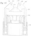
- FIG. 13shows an alternative embodiment of a crimping device 100 comprising a housing, a valve holder or pusher member 104 and an actuator or knob 106.
- the housingcan comprise a unitary, generally cylindrical structure.
- the housingcan comprise or two or more separable housing components as described above.
- the housingcan include a first housing component 102 and a second housing component (not shown). When assembled together, the first housing component 102 and the second housing component can form a generally cylindrical or tubular shape. Both the first and the second housing components can include releasable, mating locking features that are configured to engage each other and retain the housing components in their assembled state.
- each housing componentcan include one or more fins 108 extending from the proximal end of the housing component (shown on the first housing component 102 in FIG. 13 ), for example two such fins 108 on diametrically opposed sides of an outlet 110.
- One of the fins 108 on the first housing component 102can include a threaded hole 112 and the other fin 108 can include a non-threaded hole 114.
- the non-threaded 114 holemay have a larger diameter of the threaded hole 112.
- the threaded hole 112can be configured to align up with a non-threaded hole on a fin of the second housing component and the non-threaded hole 114 can be configured to align with a threaded hole on a fin of the second housing component (not shown).
- a threaded screw or knob(not shown) can be passed through first a non-threaded hole and then through the threaded hole of the first and second housing components to join and releasably retain the first and second housing components together.
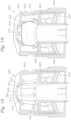
- FIGS. 14-19show an alternative embodiment of a crimping device 200 comprising a housing 202, a valve holder or pusher member 204 and a rotatable actuator or knob 206.
- FIG. 14is an exploded view of the crimping device 200.
- FIG. 15is a cross-sectional, assembled view of the crimping device 200.
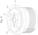
- the housing 202can have a generally cylindrical shape having an externally threaded portion 208 along a distal end portion 210 and a funnel segment 214 along a proximal end portion 220 in communication with an outlet opening 212.
- the housing 202comprises a unitary, generally cylindrical structure.
- the housingcan comprise an assembly of a plurality of separable housing components, as described above in connection with the crimping device 10.
- the funnel segment 214comprises a conical or funnel shaped wall 216 that is tapered from a first, greater diameter adjacent an intermediate portion 218 of the housing 202 to a second, smaller diameter at the outlet 212.
- the housing 202can further comprise internal tapered wall 222 extending from the distal end portion 210 of the housing 202 to approximately adjacent the distal end of the funnel segment 214.
- the internal tapered wall 222tapers from a first larger diameter to a second, smaller diameter moving in a direction from the distal end portion 210 to the proximal end portion 220.
- the wall 222is tapered at a smaller angle relative to a longitudinal axis A of the crimping device than the funnel segment, which is tapered at a steeper angle relative to the longitudinal axis A.
- the wall 222can be tapered at the same angle as the funnel segment 214, or at a greater angle than the funnel segment 214.
- the wall 222includes a plurality of circumferentially spaced ribs 224 extending longitudinally along a portion or the entire length of the wall 222 and radially inwardly extending toward the longitudinal axis A.
- the width of the ribs(the width being the dimension extending from the wall 222 toward the longitudinal axis A) can increase along their length from a smaller width adjacent the distal end portion 210 to a greater width adjacent the proximal end portion 220.
- the ribs 224function to prevent or at least minimize axial deformation of a prosthetic valve 250 (see FIG. 19 ) during radial compression and/or assist in alignment of the connection features of the prosthetic valve with mating features of the delivery apparatus.
- the ribs 224can also begin to radial compress a prosthetic valve 250 from the fully expanded diameter to a partially crimped diameter before it enters the funnel segment 214 where it is then crimped from the partially crimped diameter to the fully crimped diameter for loading into a delivery apparatus.
- the housing 202can have two crimping sections that can crimp the prosthetic valve at different rates due to the different tapering angles of the two sections.
- the wall 222 and the ribs 224are tapered at a smaller angle relative to the longitudinal axis A than is the funnel segment 214, in which case the first crimping section (defined by the ribs 224) initially crimps the prosthetic valve a first amount and then is further crimped by the second crimping section (defined by the funnel segment 214) a second amount greater than the first amount.
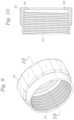
- the pusher member 204can comprise a generally cylindrical or tubular main body 226, an annular ledge 230 at the proximal end of the main body, and a plurality of circumferentially spaced, radially extending fins 228 extending from the ledge 230.
- the fins 228can be configured to be slidably disposed between the ribs 224 of the housing 202 such that as the pusher member 204 moves axially with respect to the housing 202, the fins 228 slide between the ribs 224.
- Each of the fins 228can have the shape of an angular segment that flares or widens in width extending in a radial direction away from the annular ledge 230 so as to generally correspond to the shape of the spaces between the ribs 224, as best shown in FIG. 18 .
- the annular ledge 230is configured to abut an adjacent end 232 of the prosthetic valve 250 when pushing the prosthetic valve through the housing 202.
- the pusher member 204can have an annular recess (similar to the recess 44 of the valve holder 22) or a similar feature that is configured to hold or retain an end portion of a prosthetic valve as it is pushed through the housing 202.
- the actuator 206can have internal threads 234 configured to engage the external threads 208 of the housing 202 such that rotation of the actuator 206 causes the actuator 206 to move axially along the length of the housing 202.
- the actuator 206can surround the pusher member 204 and can be coupled to the pusher member 204 such that axial movement of the actuator 206 (through rotation of the actuator 206 relative to the pusher member 204 and the housing 202) causes corresponding axial movement of the pusher member 204 through the housing 202.
- the main body of the pusher member 204can be formed with resilient locking features 238 configured to form a snap fit connection with an inwardly turned radial ledge 240 of the actuator 206.
- the crimping device 200can be used to crimp a prosthetic valve 250 in the manner described above in connection with the crimping device 10.
- the prosthetic valve 250can be inserted into the housing 202.
- the pusher member 204(which can be preassembled to the actuator 206) is inserted into the housing 202 so as to engage an adjacent end 232 of the prosthetic valve 250 while the actuator 206 is screwed onto the outside of the housing 202.
- the housing 202, the prosthetic valve 250, the pusher member 204, and the actuator 206can be positioned co-axially around the shaft of a delivery apparatus.
- the actuator 206As the actuator 206 is rotated relative to the housing 202, the actuator 206 moves axially along the housing 202, pushing the pusher member 204 through the housing 202, which in turn pushes the prosthetic valve 250 through the housing 202. As prosthetic valve 250 is pushed through the tapered wall segment 222 and the funnel segment 214, the prosthetic valve is radially compressed and pushed outwardly through the outlet 212. In particular embodiments, the prosthetic valve 250 can be pushed directly from the crimping device 200 into a sheath of a delivery apparatus (not shown).
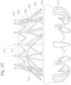
- FIG. 20is a side elevation view of an exemplary prosthetic valve 300 that can be crimped using any of the crimping devices disclosed herein.
- the prosthetic valve 300comprises a radially expandable and compressible metal frame 302 supporting a plurality of leaflets 304 inside of the frame.
- the prosthetic valve 300can also include a sealing member 306 (e.g., a fabric skirt) secured on the outside of the frame 302 and configured to create a seal against a native valve annulus.
- the prosthetic valve 300is self-expandable with the frame 302 being formed from a self-expanding metal (e.g ., Nitinol).
- the frame 302can comprise a main body 303 and a first set of anchors 308 and a second set of anchors 310 extending toward each other from opposing portions of the main body 303.
- the prosthetic valve 300is a prosthetic mitral valve and the anchors 308 are configured to help anchor the prosthetic valve 300 in the left atrium and the anchors 310 are configured to help anchor the prosthetic valve 300 in the left ventricle.
- the end of the frame 302 opposite the anchors 310can include a plurality of connecting arms 312 having enlarged end portions 314.
- the end portions 314are configured to engage mating features of a delivery apparatus to form a releasable connection between the prosthetic valve and the delivery apparatus.
- the plurality of ribs 224can aid in the alignment of the prosthetic valve 300.
- the prosthetic valve 300can be aligned within the crimping device such that one or both of the first and second set of anchors 308 and 310 are disposed between the plurality of ribs (as shown in FIG. 19 with respect to the second set of anchors 310), thereby ensuring that the enlarged end portions 314 are positioned for engagement with the mating features of the delivery apparatus to form a releasable connection between the prosthetic valve and the delivery apparatus.
- the second set of anchors 310can be radially compressed against the main body 303 of the frame 302 of the prosthetic valve 300.
- leading end 241 ( FIG. 19 ) of the funnel segment 214can be adapted to cause the anchors 310 to bend away from the main body 303 into a substantially straightened configuration extending 180 degrees from the main body 303 as the prosthetic valve 300 moves through the funnel segment 214.
- FIG. 21shows the distal end portion of an exemplary delivery apparatus 400 that can be used to deliver and implant the prosthetic valve 300 in a patient's body. Any of the crimping devices disclosed herein can be used to crimp the prosthetic valve 300 and load it onto the delivery apparatus 400.
- the delivery apparatus 400generally comprises an outer sheath 402, a first shaft 404 extending coaxially through the sheath 402, and a second shaft 406 extending coaxially through the first shaft 404.
- a nose cone 408can be attached to the distal end portion of the second shaft 406.
- the proximal end portions of the sheath 402, the first shaft 404, and the second shaft 406can be coupled to a handle and each of these components can be moveable axially relative to each other.
- a valve-retaining member 410can be connected to the distal end portion of the first shaft 404 and can include a plurality of circumferentially spaced slots 412 sized to receive the connecting arms 312 of the prosthetic valve 300.
- the valve-retaining member 410initially can be outside of the sheath 402.
- the connecting arms 312can be placed within respective slots 412 of the valve-retaining member 410.
- the enlarged end portions 314can be positioned within an annular slot 414 proximal to slots 412 to prevent axial separation of the prosthetic valve from the valve-retaining member.
- the sheath 402can be advanced distally over the valve-retaining member 410 and the prosthetic valve 300 so that the prosthetic valve can be delivered and implanted in a patient's body using the delivery apparatus 400.
- the delivery apparatus 400is inserted into a patient's vasculature and the distal end portion is positioned at or adjacent the desired implantation site ( e.g ., the native mitral valve)
- the sheath 402can be retracted proximally to deploy the prosthetic valve 300 from the sheath 402, allowing the prosthetic valve to expand under its own resiliency.
- the connecting arms 312can expand radially away from their engagement with the slots 412, thereby de-coupling the prosthetic valve from the delivery apparatus.
Landscapes
- Health & Medical Sciences (AREA)
- Engineering & Computer Science (AREA)
- Biomedical Technology (AREA)
- Cardiology (AREA)
- Oral & Maxillofacial Surgery (AREA)
- Transplantation (AREA)
- Heart & Thoracic Surgery (AREA)
- Vascular Medicine (AREA)
- Life Sciences & Earth Sciences (AREA)
- Animal Behavior & Ethology (AREA)
- General Health & Medical Sciences (AREA)
- Public Health (AREA)
- Veterinary Medicine (AREA)
- Mechanical Engineering (AREA)
- Prostheses (AREA)
Description
- This disclosure relates to systems and methods for crimping a prosthetic valve for delivery into a body.
- The human heart can suffer from various valvular diseases. These valvular diseases can result in significant malfunctioning of the heart and ultimately require replacement of the native valve with an artificial valve. There are a number of known artificial valves and a number of known methods of implanting these artificial valves in humans. Because of the drawbacks associated with conventional open-heart surgery, percutaneous and minimally-invasive surgical approaches are garnering intense attention. In one technique, a prosthetic valve is configured to be implanted in a much less invasive procedure by way of catheterization. For example, collapsible transcatheter prosthetic heart valves can be crimped to a compressed state and percutaneously introduced in the compressed state on a catheter and expanded to a functional size at the desired position by balloon inflation or by utilization of a self-expanding frame or stent.
- A prosthetic valve for use in such a procedure can include a radially collapsible and expandable frame to which leaflets of the prosthetic valve can be coupled. The leaflets typically are made of biological materials such as pericardium valves or harvested valves. For improved function after deployment, it is often desirable to package and store such valves in the open (i.e., expanded) diameter inside a preserving solution up until the time the valve is mounted on a delivery device for implantation. Using this procedure, it may be necessary to crimp the valve in the operation room a few minutes before implantation, therefore precluding pre-crimping by the manufacturer. Thus many crimping devices are now shipped as a disposable accessory along with the valve and delivery system, thus increasing the importance of portability of such crimping devices.
- Generally, conventional crimping devices operate by one of two methods. In one method, a stent is driven through a cone-like surface, which compresses the stent to a smaller diameter. For example, a static conical tube can be passed over a stent, thereby reducing its diameter. This method typically is used for crimping prosthetic valves having self-expanding metal frames (e.g., frames made of Nitinol), which are easily deformable. Self-expandable prosthetic valves typically are pushed from the conical tube of the crimping device into a sheath of a delivery apparatus, which retains the prosthetic valve in a radially compressed state. The second crimping method uses crimping jaws to create a cylinder-like surface that can change diameter. This method typically is used for crimping prosthetic valves having plastically-expandable frames (e.g., frames made of stainless steel or cobalt chromium alloys).
- Self-expandable prosthetic valves typically have multiple connection features extending from the frame that form a releasable connection with the distal end of the delivery apparatus. Once the prosthetic valve has been deployed from the sheath inside the patient's body, the physician can release the connection between the delivery apparatus and the connection features of the prosthetic valve. A challenge in crimping self-expandable prosthetic valves involves the ability of the physician to easily and quickly crimp and load a prosthetic valve into a sheath of a delivery apparatus while aligning and connecting the connection features of the prosthetic with mating connection features of the delivery apparatus. There thus remains a need for an improved crimping device that addresses these and other disadvantages in the prior art.
US 2015/297381 discloses a method and apparatus for compressing a stent to a compressed condition and/or for loading a stent for a delivery catheter.- The invention relates to a crimping device as defined by claim 1. An exemplary embodiment of a crimping device for crimping a radially expandable and compressible prosthetic valve can include a housing configured to receive a prosthetic valve in a radially expanded state. The housing member can include a funnel segment and an outlet in communication with the funnel segment. The crimping device can further include an actuator rotatably coupled to the housing, wherein rotation of the actuator relative to the housing causes the prosthetic valve to move axially through the funnel segment such that at least a portion of the prosthetic valve compresses radially by engagement with the funnel segment and exits the crimping device via the outlet. Rotation of the actuator can cause the actuator to move axially over the housing.
- Some embodiments of the crimping device can further comprise a pusher member configured to abut the prosthetic valve within the housing, wherein rotation of the actuator causes axial movement of the pusher member relative to the housing, thereby pushing the prosthetic valve through the housing. The pusher member can comprise an internal cavity, the internal cavity comprising a plurality of ribs configured to contact the prosthetic valve during radial compression. Additionally and/or alternatively, the pusher member can include an annular groove configured to receive an end portion of the prosthetic valve. The pusher member can be rotatably coupled to the actuator such that the actuator is rotatable relative to the pusher member. The pusher member can comprise releasable locking features for releasable engagement with the actuator.
- In some embodiments of the crimping device, the housing can comprise two or more housing components that form a generally cylindrical shape when assembled to form the housing. A retaining member can be configured to releasably retain the two or more housing components together.
- Additionally and/or alternatively, an exemplary crimping device for crimping a radially expandable and compressible prosthetic valve can comprise a housing having an outlet, the housing member configured to receive a prosthetic valve in a radially expanded state, and a pusher member that is axially movable relative to the housing, wherein the pusher member is configured to abut an end of the prosthetic valve and axial movement of the pusher member relative to the housing causes radial compression of the prosthetic valve and axial movement of the prosthetic valve through the outlet in a radially compressed, delivery configuration. The crimping device can further comprise an actuator that is rotatable relative to the housing and the pusher member to cause axial movement of the pusher member relative to the housing.
- In some embodiments, an internal surface of the housing can include a plurality of ribs configured to receive a prosthetic valve in a radially expanded state. Additionally and/or alternatively, the pusher member can further include a plurality of fins disposed between the plurality of ribs and configured to slidingly engage the plurality of ribs during axial movement of the pusher member. The housing member can further comprise a tapered internal wall that terminates at the outlet. The internal wall can cause radial compression of the prosthetic valve during axial movement of the pusher member relative to the housing. In some embodiments, the pusher member can be rotatably coupled to the actuator such that the actuator is rotatable relative to the pusher member.
- An exemplary method for crimping a prosthetic valve can comprise rotating an actuator of a crimping device relative to a housing of the crimping device, wherein the housing includes a funnel in communication with an outlet of the crimping device, and slidingly engaging the prosthetic valve with the funnel such that at least a portion of the prosthetic valve compresses radially and exits the crimping device via the outlet. In some embodiments, the method can further comprise advancing the prosthetic valve out of an outlet of the crimping device and into a sheath of a delivery apparatus.
- In some embodiments, the funnel can comprise a plurality of ribs extending radially inward toward a longitudinal axis of the crimping device and the method for crimping can further comprise aligning at least a portion of a frame of the prosthetic valve within the plurality of ribs. The housing can comprise two or more housing components, wherein each housing component comprises a portion of the funnel. In some embodiments the method can further comprise assembling the two or more housing components and placing the housing co-axially around a delivery apparatus prior to crimping of the prosthetic valve. Additionally and/or alternatively, the method can comprise disassembling the two or more housing components and removing them from the delivery apparatus.
- The foregoing and other objects, features, and advantages of the invention will become more apparent from the following detailed description, which proceeds with reference to the accompanying figures.
FIG. 1 is a cross-sectional view of an exemplary crimping device and a prosthetic valve shown being crimped and loaded onto a delivery apparatus.FIG. 2 is a cross-sectional, partially exploded view of the crimping device ofFIG. 1 .FIG. 3 is a side view of a housing component of the crimping device ofFIG. 1 .FIG. 4 is a cross-sectional view of the housing component ofFIG. 3 taken along line 4-4 ofFIG. 3 .FIG. 5 is a perspective view of the housing component ofFIG. 3 .FIG. 6 is a perspective view of another housing component that is complimentary to the one shown inFIG. 5 .FIG. 7 is a perspective view of a retaining ring of the crimping device ofFIG. 1 .FIG. 8 is a perspective view of a housing assembly of the crimping device ofFIG. 1 comprising the components shown inFIGS. 5-7 .FIG. 9 is a perspective view of an actuator of the crimping device ofFIG. 1 .FIG. 10 is a cross-sectional view of the actuator ofFIG. 9 taken alone line 10-10.FIG. 11 is a perspective view of a valve holder of the crimping device ofFIG. 1 .FIG. 12 is a cross-sectional view of the valve holder ofFIG. 11 taken along line 12-12.FIG. 13 is a cross-sectional view of a crimping device, according to another embodiment.FIG. 14 is a cross-sectional, exploded view of a crimping device, according to another embodiment.FIG. 15 is a cross-sectional, assembled view of the crimping device ofFIG. 14 .FIG. 16 is a top perspective view of a housing of the crimping device ofFIG. 14 .FIG. 17 is a top perspective view of a pusher member of the crimping device ofFIG. 14 .FIG. 18 is a cross-sectional perspective view of the crimping device ofFIG. 14 .FIG. 19 is a cross-sectional perspective view of the crimping device ofFIG. 14 and a prosthetic valve being crimped by the crimping device.FIG. 20 is a side elevation view of an exemplary prosthetic valve that can be crimped using any of the crimping devices disclosed herein.FIG. 21 is a side elevation view of the distal end portion of an exemplary delivery apparatus that can be used to the deliver and implant the prosthetic valve ofFIG. 20 .- For purposes of this description, certain aspects, advantages, and novel features of the embodiments of this disclosure are described herein. Features, integers, characteristics, compounds, chemical moieties or groups described in conjunction with a particular aspect, embodiment or example of the invention are to be understood to be applicable to any other aspect, embodiment or example described herein unless incompatible therewith. All of the features disclosed in this specification (including any accompanying claims, abstract and drawings), and/or all of the steps of any method or process so disclosed, may be combined in any combination, except combinations where at least some of such features and/or steps are mutually exclusive. The invention extends to any novel one, or any novel combination, of the features disclosed in this specification (including any accompanying claims, abstract and drawings), or to any novel one, or any novel combination, of the steps of any method or process so disclosed.
- Although the operations of some of the disclosed methods are described in a particular, sequential order for convenient presentation, it should be understood that this manner of description encompasses rearrangement, unless a particular ordering is required by specific language. For example, operations described sequentially may in some cases be rearranged or performed concurrently. Moreover, for the sake of simplicity, the attached figures may not show the various ways in which the disclosed methods can be used in conjunction with other methods.
- As used herein, the terms "a", "an", and "at least one" encompass one or more of the specified element. That is, if two of a particular element are present, one of these elements is also present and thus "an" element is present. The terms "a plurality of" and "plural" mean two or more of the specified element.
- As used herein, the term "and/or" used between the last two of a list of elements means any one or more of the listed elements. For example, the phrase "A, B, and/or C" means "A", "B,", "C", "A and B", "A and C", "B and C", or "A, B, and C."
- As used herein, the term "coupled" generally means physically coupled or linked and does not exclude the presence of intermediate elements between the coupled items absent specific contrary language.
FIG. 1 shows an exemplary system for crimping a prosthetic valve and other crimpable, implantable medical devices, such as stents, grafts, etc. The illustrated system comprises a crimpingdevice 10 and a radially expandable and compressibleprosthetic valve 12, shown positioned within the crimpingdevice 10. The crimpingdevice 10 is configured to reduce the diameter of theprosthetic valve 12 from a fully expanded configuration to a radially compressed, delivery configuration for delivery into a patient. Theprosthetic valve 12 is shown schematically inFIG. 1 for purposes of illustration.FIG. 20 is a more detailed illustration of an exemplary prosthetic valve that can be used with any of the crimping devices disclosed herein.- The exemplary system shown in
FIG. 1 can further comprise adelivery apparatus 14 or a portion thereof. The delivery apparatus can comprise an inner shaft orcatheter 15 and anouter sheath 16, which is sized to retain theprosthetic valve 12 in the radially compressed configuration for delivery into a patient. Theprosthetic valve 12 can comprise any radially collapsible and expandable prosthetic valve, such as a prosthetic heart valve. Theprosthetic valve 12 can be radially collapsible and expandable between an expanded configuration and a delivery configuration. Theprosthetic valve 12 can be self-expandable or plastically expandable. A self-expandable valve can have a frame formed from a self-expanding metal (e.g., Nitinol). A plastically expandable valve can have a frame formed from a plastically deformable metal (e.g., stainless steel or cobalt chromium alloy). - After the
prosthetic valve 12 is crimped onto thedelivery apparatus 14 in the delivery configuration, theprosthetic valve 12 can be removed from the crimpingdevice 10. In some embodiments, theprosthetic valve 12 and thedelivery apparatus 14 can be advanced through an outlet of the crimpingdevice 10 such that the crimpingdevice 10 remains positioned around a portion of thedelivery apparatus 14 that is distal to theprosthetic valve 12. In other embodiments, the crimpingdevice 10 or components thereof can be configured to separate into pieces or open, such as like a clam shell, such that the crimpingdevice 10 can be removed laterally from thedelivery apparatus 14 andprosthetic valve 12, as further describe below. After theprosthetic valve 12 is removed from the crimpingdevice 10, theprosthetic valve 12 and thedelivery apparatus 14 can be introduced into a patient. - As shown in
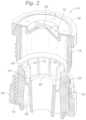
FIG. 2 , portions of the crimpingdevice 10 can be removably coupled to each other, for example via a threaded engagement. For example, the crimpingdevice 10 in the illustrated embodiment comprise ahousing 18 threadably coupled to anactuator 20 in the form of a rotatable knob. The crimpingdevice 10 can further comprise a pusher member or valve holder 22 (also referred to as a pedestal member 22) axially movable with respect to thehousing member 18. FIGS. 3-6 show the generallyrigid housing 18 within which theprosthetic valve 12 can be positioned. Thehousing 18 in the illustrated embodiment comprises an assembly comprising first and secondseparable housing component housing component portion 24 comprising external threads on an outer surface of the housing component adjacent adistal end 26, anoutlet 28 at aproximal end 30, and aninternal funnel segment 32. Thefunnel 32 segment of eachhousing component wall 34 that terminates at theoutlet 28. For example, eachfunnel segment 32 can taper from a first, greater diameter adjacent anintermediate portion 36 of thehousing component outlet 28. The diameter of theoutlet 28 can be approximately the desired diameter of theprosthetic valve 12 in the radially compressed, delivery configuration. In some embodiments, theoutlet 28 can be flush with anouter rim portion 29 at theproximal end 30 but in other embodiments theoutlet 28 can be recessed with respect to or extend beyond therim portion 29.- Each
housing component housing components housing components housing components first housing component 19a has diametrically opposed recesses 62 formed in the longitudinal edges of thefirst housing component 19a (FIG. 5 ), while thesecond housing component 19b has diametrically opposedprotrusions 64 formed in the longitudinal edges of thesecond housing component 19b (FIG. 6 ). Therecesses 62 are sized to receive correspondingprotrusions 64 when thehousing components - In the assembled stated, the
external threads 24 of thehousing components housing assembly 18. The external threads of thehousing assembly 18 are configured to mate withinternal threads 54 of theactuator 20 to produce relative axial motion between the actuator 20 and thehousing assembly 18 upon rotation of theactuator 20 relative to thehousing assembly 18, as further described below. - The first and
second housing components device 10 from thedelivery apparatus 14 after the prosthetic valve is loaded onto the delivery apparatus. For example, as shown inFIGS. 2 and7 , the crimpingdevice 10 can further comprise a retaining member 38 (also referred to as a retaining ring) configured to encircle thehousing components housing components member 38 can include a grippinginterface 40 for easy gripping and use by a user. The grippinginterface 40 can include, for example, a plurality of circumferentially spacedribs 41. - The retaining
member 38 can include an internalannular surface 56 that can be sized to slide over and form a frictional fit with the proximal end portions of thehousing components housing components housing components housing assembly 18 and remove it from thedelivery apparatus 14. The retainingmember 38 can include one ormore notches 58, such as two diametricallyopposed notches 58 as shown inFIG. 7 . Thenotches 58 can be configured to receive corresponding protrusions 60 extending from the outer surfaces of thehousing components member 38 in place during use.FIG. 4 shows a protrusion 60 extending from the outer cylindrical surface offirst housing component 19a. Thesecond housing component 19b can include an identical protrusion 60 located diametrically opposed to the one on thefirst housing component 19a. - In certain embodiments, other techniques or mechanisms can be used to secure the retaining
member 38 on thehousing components notches 58 or other portions of the retainingmember 38 can be configured to form a snap-fit connection with corresponding portions of thehousing components member 38 can be have a threaded portion (e.g., internal threads) that engage corresponding threads (e.g., external threads) on thehousing components - In alternative embodiments, the
housing components housing components member 38. For example, thefirst housing component 19a can have features that form a releasable snap-fit connection with corresponding mating features of thesecond housing component 19b. - In alternative embodiments, the
housing assembly 18 can comprise a single cylindrical housing component or member rather than multiple, separable components. In such alternative embodiments, the retainingmember 38 would not be required. In still alternative embodiments, thehousing assembly 18 can comprise more than two housing components, for example, three, four, or more separable housing components that can be assembled into a cylindrical form. - As noted above, the crimping
device 10 can further comprise anactuator 20 and avalve holder 22. The engagement of theinner threads 54 of theactuator 20 with theexternal threads 24 of thehousing assembly 18 is such that rotation of theactuator 20 in one direction relative to thehousing assembly 18 causes theactuator 20 to move proximally relative to thehousing assembly 18 in the direction indicated byarrow 88 inFIG. 1 . Rotation of theactuator 20 in the opposite direction causes theactuator 20 to move distally relative to thehousing assembly 18 in the direction indicated byarrow 90 inFIG. 1 . - As used herein, the term "proximal" or "proximally" means closer to or in a direction toward the user using the
delivery apparatus 14. Thus, the proximal direction indicated byarrow 88 is toward a handle (not shown) of thedelivery apparatus 14 and the user. As used herein, the term "distal" or "distally" means farther or in a direction away from the user using thedelivery apparatus 14. Thus, the distal direction indicated byarrow 90 extends away from the handle of thedelivery apparatus 14 and the user. - In the illustrated embodiment, the crimping
device 10 is arranged on thedelivery apparatus 14 at a location distal to thesheath 16 and such that theactuator 20 defines the distal end of the crimpingdevice 10 and the retainingmember 38 defines the proximal end of the crimpingdevice 10. However, it should be understood that the crimpingdevice 10 can be placed on thedelivery apparatus 14 in a reverse position at a location proximal to a proximal opening of a sheath with theactuator 20 defining a proximal end of the crimpingdevice 10 and the retainingmember 38 defining the distal end of the crimpingdevice 10. Thus, it can be appreciated that the terms "proximal" and "distal" when used to describe components of the crimping device and their operation, these terms are used as a matter of convenience and not require a certain orientation of the crimping device relative to the delivery apparatus or the user. - As best shown in
FIGS. 11 and 12 , thevalve holder 22 can be generally cylindrical and sized to fit within an axially extending bore 42 of thehousing assembly 18. Thevalve holder 22 is configured to hold at least a portion of theprosthetic valve 12 and push theprosthetic valve 12 axially through thebore 42 and thefunnel segment 32 to effect crimping of theprosthetic valve 12. As shown, thevalve holder 22 can comprise an internalannular recess 44 that is configured to engage, abut, or receive afirst end portion 46 of theprosthetic valve 12. Theannular recess 44 can include anannular lip 48 configured to hold thefirst end portion 46 of theprosthetic valve 12 within therecess 44. - The
annular recess 44 can be in communication with a larger internal cavity or bore 66 formed within aproximal end portion 68 of thevalve holder 22. The wall of thecavity 66 is formed with a plurality of circumferentially spacedribs 70 that extend longitudinally along and radially inwardly from the inner surface of thecavity 66. Theribs 70 can help support theprosthetic valve 12 such that there is less axial deformation of theprosthetic valve 12 during radial compression of theprosthetic valve 12. Theribs 70 can further assist in the proper placement of theprosthetic valve 12 in the crimpingdevice 10. The number of plurality ofribs 70 can vary depending on the type and/or size of prosthetic valve to be crimped. - As further shown in
FIGS. 1 and12 , adistal end portion 72 of thevalve holder 22 can have anaxially extending bore 82 that is in communication with thecavity 66 within theproximal end portion 68 of the valve holder. In this manner, thebore 82 and thecavity 66 form an axially extending passageway or lumen extending completely through thevalve holder 22 to permit thedelivery catheter 14 to be inserted through thevalve holder 22. - The
valve holder 22 can be rotatably coupled to theactuator 20 so as to permit rotation of theactuator 20 relative to thevalve holder 22 and effect axial movement of theactuator 20 and thevalve holder 22 relative to thehousing assembly 18 upon rotation of the actuator. To such ends, thedistal end portion 72 of thevalve holder 22 can be formed with one or more releasable locking features 74 (e.g., two diametrically opposed locking features 74 in the illustrated embodiment) configured to releasably engage theactuator 20. For example, as best shown inFIG. 1 , each lockingfeature 74 can comprise adeflectable lip 76 and a notch or groove 78 that is sized to receive an inwardly turnedannular ledge 80 of theactuator 20. Thelips 76 can be deflected inwardly when pressed against theledge 80, which allows theledge 80 to slide into thegrooves 78, thereby forming a snap-fit connection between theledge 80 and the locking features 74. - The
grooves 78 can be slightly oversized relative to theledge 80 to permit rotation of theledge 80 within thegrooves 78 upon rotation of theactuator 20 relative to thevalve holder 22. Due to the threaded engagement of theactuator 20 and thehousing assembly 18, rotation of theactuator 20 is effective to cause relative axial movement between the actuator 20 and thehousing assembly 18. Theledge 80 in engagement with thegrooves 78 transfers axial movement of theactuator 20 to thevalve holder 22 such that axial movement of theactuator 20 is effective to move thevalve holder 22 axially relative to thehousing assembly 18 in the same direction. Thevalve holder 22 in turn pushes theprosthetic valve 12 axially though thehousing assembly 18. Thus, rotation of theactuator 20 relative to thehousing assembly 18 can urge thevalve holder 22 against thefirst end 46 of theprosthetic valve 12 thereby forcing theprosthetic valve 12 against the taperedwalls 34 of thefunnel 32, thereby causing theprosthetic valve 12 to radially compress as it is pushed through thefunnel 32 and outwardly through theoutlet opening 28. - If desired, the
actuator 20 can be removed from thevalve holder 22 by pressing thelips 76 of the locking features inwardly past the radial innermost edge of theledge 80, which allows theactuator 20 to be slid axially away from and out of engagement with thedistal end portion 72 of thevalve holder 22. In other embodiments, theactuator 20 need not be removable from thevalve holder 22 and instead can be permanently coupled to thevalve holder 22 but otherwise allows for relative rotation of theactuator 20 and thevalve holder 22 as previously described above. - As shown in
FIG. 11 , thevalve holder 22 can have one or more longitudinally extending, external ribs or protrusions 84 (two diametricallyopposed ribs 84 in the illustrated embodiment). Theexternal ribs 84 are sized to be received in respective longitudinal slots 86 in eachhousing component FIG. 3 ). Although only the slot 86 of thefirst housing component 19a is shown inFIG. 3 , thesecond housing component 19b has an identical slot 86 diametrically opposed to the one in thefirst housing component 19a. The engagement of theribs 84 within the slots 86 can be used to align thevalve holder 22 within thehousing assembly 18 and prevents any rotation of thevalve holder 22 relative to theactuator 20 and thehousing assembly 18 upon rotation of theactuator 20. - The threaded engagement of the
actuator 20 and thehousing assembly 18 can allow a user to precisely control the advancement of theprosthetic valve 12 out of the crimpingdevice 10 and/or radial compression of theprosthetic valve 12. The crimpingdevice 10 further allows for a one-person operation of the crimpingdevice 10 and a repeatable, predictable procedure for crimping and loading aprosthetic valve 12. Some embodiments of theprosthetic valve 12 can include connection features that form a releasable connection with mating features of the delivery apparatus 14 (the connection features are located at the end of the prosthetic valve opposite the end in engagement with the valve holder 22) (e.g., see connectingarms 312 ofprosthetic valve 300, described in further detail below). The connection features of the prosthetic valve have to be radially compressed while maintaining rotational alignment with the mating features of the delivery apparatus. The crimpingdevice 10 allows a single operator to control crimping of the prosthetic valve while maintaining the rotational alignment of the connection features of the prosthetic valve with the mating features of the delivery apparatus. As the prosthetic valve is advanced out of theoutlet 28 of the crimpingdevice 10, the operator can connect the connection features of the prosthetic valve to the mating features of the delivery apparatus. - In the embodiment shown in
FIG. 3 , for example, theprosthetic valve 12 can be advanced through theoutlet 28 of the crimpingdevice 10 and into thesheath 16 of thedelivery apparatus 14. Thesheath 16 can be a tubular structure configured to contain theprosthetic valve 12 in the delivery configuration. The crimpingdevice 10 can then be removed from thedelivery apparatus 14 by sliding it distally off the inner shaft 15 (in the direction of arrow 90). - In some embodiments, the
delivery apparatus 14 can include a nose cone or tip portion at the distal end of theinner shaft 15, which can prevent removal of the crimpingdevice 10 by sliding it distally off theinner shaft 15. In such cases, the crimpingdevice 10 can be disassembled by rotating the actuator 20 in the opposite direction to cause theactuator 20 to move distally relative to the housing assembly 18 (in the direction of arrow 90) until theactuator 20 is disengaged and removed from thehousing assembly 18. The retainingmember 38 can be slid off of the proximal end of thehousing assembly 18, which then allows the first andsecond housing components delivery apparatus 14. Thevalve holder 22 desirably has a large enough lumen to be slid off thedelivery apparatus 14, such as by sliding thevalve holder 22 distally relative to theinner shaft 15 until it is removed from the distal end of the delivery apparatus. - The
delivery apparatus 14 can then be inserted into the vasculature of a patient and used to deliver theprosthetic valve 12 percutaneously to the desired implantation location using conventional techniques. The distal end of thedelivery apparatus 14 can be inserted into another device, such as an introducer sheath, which has been already inserted into a patient, to facilitate insertion of thedelivery apparatus 14 into the patient. - In some embodiments, a system comprising a crimping
device 10, adelivery apparatus 14, and aprosthetic valve 12 can be packaged and shipped from the manufacturer to the end user with theprosthetic valve 12 pre-loaded inside of the fully assembled crimpingdevice 10 coaxially mounted on the delivery apparatus. In some embodiments, the system can further comprise a sterile package enclosing the crimpingdevice 10 mounted on the distal end portion of the delivery apparatus, theprosthetic valve 12 pre-loaded in the crimping device, and the entire thedelivery apparatus 14 or just the distal end portion of the delivery apparatus on which the crimping device and the prosthetic valve are mounted. In other embodiments, the system can further comprise another device, such as an introducer sheath, to assist in inserting thedelivery apparatus 14 into a patient once the prosthetic valve has been loaded into thesheath 16. - In some embodiments, the
prosthetic valve 12 can be in a partially crimped configuration prior to being assembled within the crimpingdevice 10. For example, theprosthetic valve 12 can be pre-crimped to the partially crimped configuration using another crimping instrument, prior to being assembled into crimpingdevice 10. In the partially crimped configuration, theprosthetic valve 12 has an outer diameter that is between that of the expanded configuration and that of the delivery configuration. In some embodiments, theprosthetic valve 12 can have an outer diameter in the partially crimped configuration that is closer to the outer diameter in the delivery configuration than to the outer diameter in the expanded configuration. For example, theprosthetic valve 12 in the partially crimped configuration can be crimped about 75% of the way from the expanded configuration to the delivery configuration. The crimpingdevice 10 can also be configured to crimp theprosthetic valve 12 to the delivery configuration from the expanded configuration without first pre-crimping theprosthetic valve 12 to an intermediate partially crimped configuration. FIG. 13 shows an alternative embodiment of a crimping device 100 comprising a housing, a valve holder or pusher member 104 and an actuator or knob 106. The housing can comprise a unitary, generally cylindrical structure. Alternatively, the housing can comprise or two or more separable housing components as described above. For example, the housing can include a first housing component 102 and a second housing component (not shown). When assembled together, the first housing component 102 and the second housing component can form a generally cylindrical or tubular shape. Both the first and the second housing components can include releasable, mating locking features that are configured to engage each other and retain the housing components in their assembled state. For example, each housing component can include one or more fins 108 extending from the proximal end of the housing component (shown on the first housing component 102 inFIG. 13 ), for example two such fins 108 on diametrically opposed sides of an outlet 110. One of the fins 108 on the first housing component 102 can include a threaded hole 112 and the other fin 108 can include a non-threaded hole 114. The non-threaded 114 hole may have a larger diameter of the threaded hole 112. The threaded hole 112 can be configured to align up with a non-threaded hole on a fin of the second housing component and the non-threaded hole 114 can be configured to align with a threaded hole on a fin of the second housing component (not shown). A threaded screw or knob (not shown) can be passed through first a non-threaded hole and then through the threaded hole of the first and second housing components to join and releasably retain the first and second housing components together.FIGS. 14-19 show an alternative embodiment of a crimpingdevice 200 comprising ahousing 202, a valve holder orpusher member 204 and a rotatable actuator orknob 206.FIG. 14 is an exploded view of the crimpingdevice 200.FIG. 15 is a cross-sectional, assembled view of the crimpingdevice 200. Thehousing 202 can have a generally cylindrical shape having an externally threadedportion 208 along adistal end portion 210 and afunnel segment 214 along aproximal end portion 220 in communication with anoutlet opening 212. In the illustrated embodiment, thehousing 202 comprises a unitary, generally cylindrical structure. However, in other embodiments, the housing can comprise an assembly of a plurality of separable housing components, as described above in connection with the crimpingdevice 10.- The
funnel segment 214 comprises a conical or funnel shapedwall 216 that is tapered from a first, greater diameter adjacent anintermediate portion 218 of thehousing 202 to a second, smaller diameter at theoutlet 212. Thehousing 202 can further comprise internal taperedwall 222 extending from thedistal end portion 210 of thehousing 202 to approximately adjacent the distal end of thefunnel segment 214. The internaltapered wall 222 tapers from a first larger diameter to a second, smaller diameter moving in a direction from thedistal end portion 210 to theproximal end portion 220. In the illustrated embodiment, thewall 222 is tapered at a smaller angle relative to a longitudinal axis A of the crimping device than the funnel segment, which is tapered at a steeper angle relative to the longitudinal axis A. In other embodiments, thewall 222 can be tapered at the same angle as thefunnel segment 214, or at a greater angle than thefunnel segment 214. - The
wall 222 includes a plurality of circumferentially spacedribs 224 extending longitudinally along a portion or the entire length of thewall 222 and radially inwardly extending toward the longitudinal axis A. The width of the ribs (the width being the dimension extending from thewall 222 toward the longitudinal axis A) can increase along their length from a smaller width adjacent thedistal end portion 210 to a greater width adjacent theproximal end portion 220. Theribs 224 function to prevent or at least minimize axial deformation of a prosthetic valve 250 (seeFIG. 19 ) during radial compression and/or assist in alignment of the connection features of the prosthetic valve with mating features of the delivery apparatus. - In particular embodiments, the
ribs 224 can also begin to radial compress aprosthetic valve 250 from the fully expanded diameter to a partially crimped diameter before it enters thefunnel segment 214 where it is then crimped from the partially crimped diameter to the fully crimped diameter for loading into a delivery apparatus. Thus, in this manner, thehousing 202 can have two crimping sections that can crimp the prosthetic valve at different rates due to the different tapering angles of the two sections. In the illustrated embodiment, for example, thewall 222 and theribs 224 are tapered at a smaller angle relative to the longitudinal axis A than is thefunnel segment 214, in which case the first crimping section (defined by the ribs 224) initially crimps the prosthetic valve a first amount and then is further crimped by the second crimping section (defined by the funnel segment 214) a second amount greater than the first amount. - As best shown in
FIG. 17 , thepusher member 204 can comprise a generally cylindrical or tubularmain body 226, anannular ledge 230 at the proximal end of the main body, and a plurality of circumferentially spaced, radially extendingfins 228 extending from theledge 230. Thefins 228 can be configured to be slidably disposed between theribs 224 of thehousing 202 such that as thepusher member 204 moves axially with respect to thehousing 202, thefins 228 slide between theribs 224. Each of thefins 228 can have the shape of an angular segment that flares or widens in width extending in a radial direction away from theannular ledge 230 so as to generally correspond to the shape of the spaces between theribs 224, as best shown inFIG. 18 . Theannular ledge 230 is configured to abut anadjacent end 232 of theprosthetic valve 250 when pushing the prosthetic valve through thehousing 202. - In alternative embodiments, the
pusher member 204 can have an annular recess (similar to therecess 44 of the valve holder 22) or a similar feature that is configured to hold or retain an end portion of a prosthetic valve as it is pushed through thehousing 202. - The
actuator 206 can haveinternal threads 234 configured to engage theexternal threads 208 of thehousing 202 such that rotation of theactuator 206 causes theactuator 206 to move axially along the length of thehousing 202. Theactuator 206 can surround thepusher member 204 and can be coupled to thepusher member 204 such that axial movement of the actuator 206 (through rotation of theactuator 206 relative to thepusher member 204 and the housing 202) causes corresponding axial movement of thepusher member 204 through thehousing 202. For example, the main body of thepusher member 204 can be formed with resilient locking features 238 configured to form a snap fit connection with an inwardly turnedradial ledge 240 of theactuator 206. - The crimping
device 200 can be used to crimp aprosthetic valve 250 in the manner described above in connection with the crimpingdevice 10. Briefly, theprosthetic valve 250 can be inserted into thehousing 202. The pusher member 204 (which can be preassembled to the actuator 206) is inserted into thehousing 202 so as to engage anadjacent end 232 of theprosthetic valve 250 while theactuator 206 is screwed onto the outside of thehousing 202. Although not shown, thehousing 202, theprosthetic valve 250, thepusher member 204, and theactuator 206 can be positioned co-axially around the shaft of a delivery apparatus. As theactuator 206 is rotated relative to thehousing 202, theactuator 206 moves axially along thehousing 202, pushing thepusher member 204 through thehousing 202, which in turn pushes theprosthetic valve 250 through thehousing 202. Asprosthetic valve 250 is pushed through thetapered wall segment 222 and thefunnel segment 214, the prosthetic valve is radially compressed and pushed outwardly through theoutlet 212. In particular embodiments, theprosthetic valve 250 can be pushed directly from the crimpingdevice 200 into a sheath of a delivery apparatus (not shown). FIG. 20 is a side elevation view of an exemplaryprosthetic valve 300 that can be crimped using any of the crimping devices disclosed herein. Theprosthetic valve 300 comprises a radially expandable andcompressible metal frame 302 supporting a plurality ofleaflets 304 inside of the frame. Theprosthetic valve 300 can also include a sealing member 306 (e.g., a fabric skirt) secured on the outside of theframe 302 and configured to create a seal against a native valve annulus. In certain embodiments, theprosthetic valve 300 is self-expandable with theframe 302 being formed from a self-expanding metal (e.g., Nitinol).- The
frame 302 can comprise amain body 303 and a first set of anchors 308 and a second set ofanchors 310 extending toward each other from opposing portions of themain body 303. In particular embodiments, theprosthetic valve 300 is a prosthetic mitral valve and the anchors 308 are configured to help anchor theprosthetic valve 300 in the left atrium and theanchors 310 are configured to help anchor theprosthetic valve 300 in the left ventricle. The end of theframe 302 opposite theanchors 310 can include a plurality of connectingarms 312 having enlargedend portions 314. Theend portions 314 are configured to engage mating features of a delivery apparatus to form a releasable connection between the prosthetic valve and the delivery apparatus. - As noted above, the plurality of
ribs 224 can aid in the alignment of theprosthetic valve 300. For example, theprosthetic valve 300 can be aligned within the crimping device such that one or both of the first and second set ofanchors 308 and 310 are disposed between the plurality of ribs (as shown inFIG. 19 with respect to the second set of anchors 310), thereby ensuring that theenlarged end portions 314 are positioned for engagement with the mating features of the delivery apparatus to form a releasable connection between the prosthetic valve and the delivery apparatus. As the prosthetic valve is pushed out of theoutlet 212, the second set ofanchors 310 can be radially compressed against themain body 303 of theframe 302 of theprosthetic valve 300. In alternative embodiments, the leading end 241 (FIG. 19 ) of thefunnel segment 214 can be adapted to cause theanchors 310 to bend away from themain body 303 into a substantially straightened configuration extending 180 degrees from themain body 303 as theprosthetic valve 300 moves through thefunnel segment 214. FIG. 21 shows the distal end portion of anexemplary delivery apparatus 400 that can be used to deliver and implant theprosthetic valve 300 in a patient's body. Any of the crimping devices disclosed herein can be used to crimp theprosthetic valve 300 and load it onto thedelivery apparatus 400. As shown, thedelivery apparatus 400 generally comprises anouter sheath 402, afirst shaft 404 extending coaxially through thesheath 402, and asecond shaft 406 extending coaxially through thefirst shaft 404. Anose cone 408 can be attached to the distal end portion of thesecond shaft 406. Although not shown, the proximal end portions of thesheath 402, thefirst shaft 404, and thesecond shaft 406 can be coupled to a handle and each of these components can be moveable axially relative to each other.- A valve-retaining
member 410 can be connected to the distal end portion of thefirst shaft 404 and can include a plurality of circumferentially spacedslots 412 sized to receive the connectingarms 312 of theprosthetic valve 300. During the crimping process, the valve-retainingmember 410 initially can be outside of thesheath 402. As theprosthetic valve 300 is initially pushed out of theoutlet 212 of the crimpingdevice 200, the connectingarms 312 can be placed withinrespective slots 412 of the valve-retainingmember 410. Theenlarged end portions 314 can be positioned within anannular slot 414 proximal toslots 412 to prevent axial separation of the prosthetic valve from the valve-retaining member. - As the prosthetic valve is further advanced from the crimping device, the
sheath 402 can be advanced distally over the valve-retainingmember 410 and theprosthetic valve 300 so that the prosthetic valve can be delivered and implanted in a patient's body using thedelivery apparatus 400. After thedelivery apparatus 400 is inserted into a patient's vasculature and the distal end portion is positioned at or adjacent the desired implantation site (e.g., the native mitral valve), thesheath 402 can be retracted proximally to deploy theprosthetic valve 300 from thesheath 402, allowing the prosthetic valve to expand under its own resiliency. When thesheath 402 is retracted proximally beyond the valve-retainingmember 410, the connectingarms 312 can expand radially away from their engagement with theslots 412, thereby de-coupling the prosthetic valve from the delivery apparatus. - In view of the many possible embodiments to which the principles of the disclosed invention can be applied, it should be recognized that the illustrated embodiments are only preferred examples of the invention and should not be taken as limiting the scope of the invention. Rather, the scope of the invention is defined by the following claims. We therefore claim as our invention all that comes within the scope of these claims.
Claims (15)
- A crimping device (10, 100, 200) for crimping a radially expandable and compressible prosthetic valve (12, 250, 300), the crimping device (10, 100, 200) comprising:a housing (18, 202) having an outlet (28, 212) and an internal surface, the internal surface having a plurality circumferentially spaced ribs (224) extending longitudinally along at least a portion of an inner wall (222) of the housing (18, 202) and radially inwardly from the internal surface, said plurality of ribs (224) configured to receive a prosthetic valve (12, 250, 300) in a radially expanded state;a pusher member (22, 104, 204) that is axially movable relative to the housing (18, 202), wherein the pusher member (22, 104, 204) is configured to abut an end of the prosthetic valve (12, 250, 300) and axial movement of the pusher member (22, 104, 204) relative to the housing (18, 202) causes radial compression of the prosthetic valve (12, 250, 300) and axial movement of the prosthetic valve (12, 250, 300) through the outlet in a radially compressed, delivery configuration; andan actuator (20) that is rotatable relative to the housing (18, 202) and the pusher member (22, 104, 204) to cause axial movement of the pusher member (22, 104, 204) relative to the housing (18, 202).
- The crimping device (10, 100, 200) of claim 1, wherein the pusher member (204) further includes a plurality of fins (228) disposed between the plurality of ribs (224) and configured to slidingly engage the plurality of ribs (224) during axial movement of the pusher member (204).
- The crimping device (10, 100, 200) of any one of claims 1 to 2, wherein the housing (18, 202) further comprises a tapered internal wall (34, 222) that terminates at the outlet (28, 212).
- The crimping device (10, 100, 200) of claim 3, wherein the internal wall (34, 222) causes radial compression of the prosthetic valve during axial movement of the pusher member (22, 104, 204) relative to the housing (18, 202).
- The crimping device (10, 100, 200) of any one of claims 1 to 3, wherein the pusher member (22, 104, 204) is rotatably coupled to the actuator (20) such that the actuator (20) is rotatable relative to the pusher member (22, 104, 204).
- The crimping device (10, 100, 200) of any one of claims 1 to 5, wherein the housing (18, 202) includes a funnel segment (32, 214) in communication with the outlet (28, 212), and two or more housing components (19a, 19b), wherein each housing component (19a, 19b) comprises a portion of the funnel (32, 214).
- The crimping device (10, 100, 200) of claim 6, further comprising a retaining member (38) configured to releasably retain the two or more housing components (19a, 19b) together.
- The crimping device (10, 100, 200) of any one of claims 1 to 7, wherein the pusher member (22, 104, 204) comprises releasable locking features (74) for releasable engagement with the actuator (20).
- A system for crimping a prosthetic valve comprising:a crimping device (10, 100, 200) of any one of claims 1 to 8; anda radially expandable and compressible prosthetic valve (12, 250, 300), the prosthetic valve (12, 250, 300) comprising a plurality of connection features to form a releasable connection with respective mating features of a delivery apparatus (14, 400);wherein the crimping device (10, 100, 200) is configured to radially compress the connection features while maintaining rotational alignment of the connection features with the mating features of the delivery apparatus.
- The system of claim 9, further including the delivery apparatus (14, 400).
- The system of any one of claims 9 and 10, wherein the prosthetic valve (12, 250, 300) comprises a frame (302) including a plurality of connecting arms (312) as the connection features, the connecting arms (312) having enlarged end portions (314) configured to engage the mating features of the delivery apparatus (14, 400).
- The system of claim 11, wherein the enlarged end portions (314) are configured to be pushed together as the prosthetic valve (12, 250, 300) is advanced through the crimping device (10, 100, 200).
- The system of any one of claims 11 and 12, wherein the delivery apparatus (14, 400) comprises a valve-retaining member (410) comprising a plurality of circumferentially spaced slots (412) configured to receive the connecting arms (312) of the prosthetic valve (12, 250, 300).
- The system of any one of claims 11 to 13, wherein the frame (302) comprises a main body (303), a first set of anchors (308) and a second set of anchors (310) extending toward one another from opposing portions of the main body (303);wherein the connecting arms (312) are arranged at an end of the frame (302) opposite the second set of anchors (310);wherein the second set of anchors (310) is configured to be radially compressed against the main body (303) of the frame (302) as the prosthetic valve (12, 250, 300) is advanced through the crimping device (10, 100, 200).
- The system of claim 14, wherein the delivery apparatus (14, 400) further comprises an outer sheath (402), a first shaft (404) extending coaxially through the sheath (402) and a second shaft (406) extending coaxially through the first shaft (404);wherein the valve-retaining member (410) is configured to be connected to the distal end portion of the first shaft (404) and is initially provided outside of the sheath (402);wherein the sheath (402) is configured to be advanced distally over the valve-retaining member (410) and the prosthetic valve (10, 250, 300) as the prosthetic valve (12, 250, 300) is advanced through the crimping device (10, 100, 200).
Priority Applications (1)
| Application Number | Priority Date | Filing Date | Title |
|---|---|---|---|
| EP24218744.1AEP4494610A3 (en) | 2016-06-24 | 2017-05-12 | System for crimping a prosthetic valve |
Applications Claiming Priority (4)
| Application Number | Priority Date | Filing Date | Title |
|---|---|---|---|
| US201662354371P | 2016-06-24 | 2016-06-24 | |
| US15/487,881US10639147B2 (en) | 2016-06-24 | 2017-04-14 | System and method for crimping a prosthetic valve |
| PCT/US2017/032338WO2017222669A1 (en) | 2016-06-24 | 2017-05-12 | System and method for crimping a prosthetic valve |
| EP17815864.8AEP3474778B1 (en) | 2016-06-24 | 2017-05-12 | System and method for crimping a prosthetic valve |
Related Parent Applications (1)
| Application Number | Title | Priority Date | Filing Date |
|---|---|---|---|
| EP17815864.8ADivisionEP3474778B1 (en) | 2016-06-24 | 2017-05-12 | System and method for crimping a prosthetic valve |
Related Child Applications (1)
| Application Number | Title | Priority Date | Filing Date |
|---|---|---|---|
| EP24218744.1ADivisionEP4494610A3 (en) | 2016-06-24 | 2017-05-12 | System for crimping a prosthetic valve |
Publications (3)
| Publication Number | Publication Date |
|---|---|
| EP3949903A1 EP3949903A1 (en) | 2022-02-09 |
| EP3949903C0 EP3949903C0 (en) | 2024-12-11 |
| EP3949903B1true EP3949903B1 (en) | 2024-12-11 |
Family
ID=60675145
Family Applications (3)
| Application Number | Title | Priority Date | Filing Date |
|---|---|---|---|
| EP17815864.8AActiveEP3474778B1 (en) | 2016-06-24 | 2017-05-12 | System and method for crimping a prosthetic valve |
| EP21152339.4AActiveEP3949903B1 (en) | 2016-06-24 | 2017-05-12 | System for crimping a prosthetic valve |
| EP24218744.1APendingEP4494610A3 (en) | 2016-06-24 | 2017-05-12 | System for crimping a prosthetic valve |
Family Applications Before (1)
| Application Number | Title | Priority Date | Filing Date |
|---|---|---|---|
| EP17815864.8AActiveEP3474778B1 (en) | 2016-06-24 | 2017-05-12 | System and method for crimping a prosthetic valve |
Family Applications After (1)
| Application Number | Title | Priority Date | Filing Date |
|---|---|---|---|
| EP24218744.1APendingEP4494610A3 (en) | 2016-06-24 | 2017-05-12 | System for crimping a prosthetic valve |
Country Status (6)
| Country | Link |
|---|---|
| US (3) | US10639147B2 (en) |
| EP (3) | EP3474778B1 (en) |
| CN (1) | CN109475414B (en) |
| CA (1) | CA3027699C (en) |
| ES (1) | ES3009949T3 (en) |
| WO (1) | WO2017222669A1 (en) |
Families Citing this family (47)
| Publication number | Priority date | Publication date | Assignee | Title |
|---|---|---|---|---|
| US20090276040A1 (en) | 2008-05-01 | 2009-11-05 | Edwards Lifesciences Corporation | Device and method for replacing mitral valve |
| CA2961053C (en) | 2009-04-15 | 2019-04-30 | Edwards Lifesciences Cardiaq Llc | Vascular implant and delivery system |
| NZ596179A (en) | 2009-04-29 | 2014-05-30 | Cleveland Clinic Foundation | Apparatus and method for replacing a diseased cardiac valve |
| US8652203B2 (en) | 2010-09-23 | 2014-02-18 | Cardiaq Valve Technologies, Inc. | Replacement heart valves, delivery devices and methods |
| US8449599B2 (en) | 2009-12-04 | 2013-05-28 | Edwards Lifesciences Corporation | Prosthetic valve for replacing mitral valve |
| US8579964B2 (en) | 2010-05-05 | 2013-11-12 | Neovasc Inc. | Transcatheter mitral valve prosthesis |
| US9308087B2 (en) | 2011-04-28 | 2016-04-12 | Neovasc Tiara Inc. | Sequentially deployed transcatheter mitral valve prosthesis |
| US9554897B2 (en) | 2011-04-28 | 2017-01-31 | Neovasc Tiara Inc. | Methods and apparatus for engaging a valve prosthesis with tissue |
| US9345573B2 (en) | 2012-05-30 | 2016-05-24 | Neovasc Tiara Inc. | Methods and apparatus for loading a prosthesis onto a delivery system |
| US9439763B2 (en) | 2013-02-04 | 2016-09-13 | Edwards Lifesciences Corporation | Prosthetic valve for replacing mitral valve |
| US20140277427A1 (en) | 2013-03-14 | 2014-09-18 | Cardiaq Valve Technologies, Inc. | Prosthesis for atraumatically grasping intralumenal tissue and methods of delivery |
| US9572665B2 (en) | 2013-04-04 | 2017-02-21 | Neovasc Tiara Inc. | Methods and apparatus for delivering a prosthetic valve to a beating heart |
| US10188515B2 (en)* | 2013-05-13 | 2019-01-29 | Medtronic Vascular Inc. | Devices and methods for crimping a medical device |
| US9532870B2 (en) | 2014-06-06 | 2017-01-03 | Edwards Lifesciences Corporation | Prosthetic valve for replacing a mitral valve |
| KR20170066470A (en) | 2014-09-28 | 2017-06-14 | 카디오키네틱스 인크. | Apparatuses for treating cardiac dysfunction |
| US10531951B2 (en) | 2014-11-26 | 2020-01-14 | Edwards Lifesciences Corporation | Transcatheter prosthetic heart valve and delivery system |
| WO2016153918A1 (en) | 2015-03-20 | 2016-09-29 | Cardiokinetix, Inc. | Systems and methods for delivering an implantable device |
| CA3007660A1 (en) | 2015-12-15 | 2017-06-22 | Neovasc Tiara Inc. | Transseptal delivery system |
| US10433952B2 (en) | 2016-01-29 | 2019-10-08 | Neovasc Tiara Inc. | Prosthetic valve for avoiding obstruction of outflow |
| CA3042588A1 (en) | 2016-11-21 | 2018-05-24 | Neovasc Tiara Inc. | Methods and systems for rapid retraction of a transcatheter heart valve delivery system |
| US10918473B2 (en)* | 2017-07-18 | 2021-02-16 | Edwards Lifesciences Corporation | Transcatheter heart valve storage container and crimping mechanism |
| CA3073834A1 (en) | 2017-08-25 | 2019-02-28 | Neovasc Tiara Inc. | Sequentially deployed transcatheter mitral valve prosthesis |
| CN110292463B (en)* | 2018-03-22 | 2024-08-23 | 上海微创心通医疗科技有限公司 | Implant loading device |
| CN113271890B (en) | 2018-11-08 | 2024-08-30 | 内奥瓦斯克迪亚拉公司 | Ventricular deployment of transcatheter mitral valve prosthesis |
| CA3132873A1 (en) | 2019-03-08 | 2020-09-17 | Neovasc Tiara Inc. | Retrievable prosthesis delivery system |
| CA3135753C (en) | 2019-04-01 | 2023-10-24 | Neovasc Tiara Inc. | Controllably deployable prosthetic valve |
| US11491006B2 (en) | 2019-04-10 | 2022-11-08 | Neovasc Tiara Inc. | Prosthetic valve with natural blood flow |
| ES2982566T3 (en) | 2019-04-23 | 2024-10-16 | Edwards Lifesciences Corp | Motorized implant delivery system |
| US11779742B2 (en) | 2019-05-20 | 2023-10-10 | Neovasc Tiara Inc. | Introducer with hemostasis mechanism |
| CN110251273B (en)* | 2019-05-23 | 2022-09-13 | 沛嘉医疗科技(苏州)有限公司 | Transcatheter valve delivery preloading system device |
| JP7520897B2 (en) | 2019-06-20 | 2024-07-23 | ニオバスク ティアラ インコーポレイテッド | Thin prosthetic mitral valve |
| WO2021113395A1 (en)* | 2019-12-02 | 2021-06-10 | Venarum Medical, Llc | Process for catheter loading an implantable venous valve and apparatus |
| EP4096589A1 (en)* | 2020-01-28 | 2022-12-07 | Edwards Lifesciences Corporation | Apparatus and methods for loading and deploying implants from delivery apparatuses |
| EP4247297A1 (en) | 2020-12-18 | 2023-09-27 | Edwards Lifesciences Corporation | Storage jar assembly for aprosthetic heart valve |
| CN113332000B (en)* | 2021-07-12 | 2024-04-26 | 上海臻亿医疗科技有限公司 | Bracket loading system and method |
| JP7730980B2 (en)* | 2021-07-13 | 2025-08-28 | ボストン サイエンティフィック サイムド,インコーポレイテッド | Apparatus for compressing a replacement heart valve implant - Patent Application 20070122997 |
| WO2023064362A1 (en)* | 2021-10-13 | 2023-04-20 | Boston Scientific Scimed, Inc. | Device and method for compressing and loading a stent |
| EP4422552A1 (en)* | 2021-10-27 | 2024-09-04 | Edwards Lifesciences Corporation | System and method for crimping and loading a prosthetic heart valve |
| US20250275845A1 (en)* | 2021-12-15 | 2025-09-04 | Cephea Valve Technologies, Inc. | Prosthetic Heart Valve Packaging and Attachment Assembly |
| CN119744152A (en)* | 2022-08-22 | 2025-04-01 | 美敦力公司 | Loading system for implantable medical devices |
| CN116019532B (en)* | 2022-12-13 | 2024-12-03 | 北京泰杰伟业科技股份有限公司 | Diameter-variable tissue expanding device |
| WO2024132115A1 (en)* | 2022-12-20 | 2024-06-27 | T-Heart SAS | Loading system for a stent device |
| CN118986590A (en)* | 2023-05-22 | 2024-11-22 | 上海微创心通医疗科技有限公司 | Stent assembly structure, catheter assembly and delivery system |
| CN119302779A (en)* | 2023-07-13 | 2025-01-14 | 沛嘉医疗科技(苏州)有限公司 | Storage and transfer devices for cardiac interventional valves |
| US12303388B1 (en) | 2023-11-14 | 2025-05-20 | Nanjing Drum Tower Hospital | Valve compression apparatus |
| CN117323065B (en)* | 2023-11-14 | 2024-02-23 | 南京鼓楼医院 | A valve compression device |
| WO2025117321A1 (en) | 2023-11-27 | 2025-06-05 | Edwards Lifesciences Corporation | Transcatheter heart valve delivery system solutions |
Family Cites Families (81)
| Publication number | Priority date | Publication date | Assignee | Title |
|---|---|---|---|---|
| US1438681A (en) | 1920-03-31 | 1922-12-12 | John Bath & Co Inc | Ring gauge |
| US1493515A (en) | 1923-04-07 | 1924-05-13 | Rajah Auto Supply Co | Crimping machine |
| US2079498A (en) | 1934-06-28 | 1937-05-04 | Harry A Douglas | Compressing tool |
| US2787925A (en) | 1954-06-08 | 1957-04-09 | Buchanan Electrical Prod Corp | Wire crimping tool with cam-slot actuating means |
| US2974367A (en) | 1954-09-29 | 1961-03-14 | Western Electric Co | Apparatus for making splicing-sleeve assemblies |
| US4350036A (en) | 1980-02-07 | 1982-09-21 | Vale Industries Inc. | Apparatus for pointing work pieces |
| US5230352A (en) | 1992-03-04 | 1993-07-27 | American Cyanamid Company | Medical suturing device, a single-strike die mechanism, and a method of using said die mechanism for forming the medical suturing device |
| US5626604A (en) | 1995-12-05 | 1997-05-06 | Cordis Corporation | Hand held stent crimping device |
| US5749921A (en) | 1996-02-20 | 1998-05-12 | Medtronic, Inc. | Apparatus and methods for compression of endoluminal prostheses |
| US5836952A (en) | 1996-08-21 | 1998-11-17 | Cordis Corporation | Hand-held stent crimper |
| US5913871A (en) | 1996-09-25 | 1999-06-22 | Medtronic, Inc. | Balloon modification for improved stent fixation and deployment |
| US7748248B2 (en) | 2005-03-23 | 2010-07-06 | Boston Scientific Scimed, Inc. | Stent crimping mechanisms |
| US5810873A (en) | 1997-07-15 | 1998-09-22 | Advanced Cardiovascular Systems, Inc. | Stent crimping tool and method of use |
| US6167605B1 (en) | 1997-09-12 | 2001-01-02 | Advanced Cardiovascular Systems, Inc. | Collet type crimping tool |
| US5992000A (en) | 1997-10-16 | 1999-11-30 | Scimed Life Systems, Inc. | Stent crimper |
| US6769161B2 (en) | 1997-10-16 | 2004-08-03 | Scimed Life Systems, Inc. | Radial stent crimper |
| US6082990A (en) | 1998-02-17 | 2000-07-04 | Advanced Cardiovascular Systems, Inc. | Stent crimping tool |
| DE59812219D1 (en)* | 1998-03-04 | 2004-12-09 | Schneider Europ Gmbh Buelach | Device for inserting an endoprosthesis into a catheter shaft |
| US6009614A (en) | 1998-04-21 | 2000-01-04 | Advanced Cardiovascular Systems, Inc. | Stent crimping tool and method of use |
| US6074381A (en) | 1998-10-22 | 2000-06-13 | Isostent, Inc. | Cylindrical roller stent crimper apparatus with radiation shield |
| US6558418B2 (en) | 1999-01-26 | 2003-05-06 | Edwards Lifesciences Corporation | Flexible heart valve |
| US6360577B2 (en) | 1999-09-22 | 2002-03-26 | Scimed Life Systems, Inc. | Apparatus for contracting, or crimping stents |
| US6387117B1 (en) | 1999-09-22 | 2002-05-14 | Scimed Life Systems, Inc. | Stent crimping system |
| US6352547B1 (en) | 1999-09-22 | 2002-03-05 | Scimed Life Systems, Inc. | Stent crimping system |
| US6309383B1 (en) | 2000-01-20 | 2001-10-30 | Isostent, Inc. | Stent crimper apparatus with radiation shied |
| US6629350B2 (en) | 2000-06-08 | 2003-10-07 | Tom Motsenbocker | Stent crimping apparatus and method |
| US6568235B1 (en) | 2000-08-10 | 2003-05-27 | Advanced Cardiovascular Systems, Inc. | Assembly for crimping an intraluminal device or measuring the radial strength of the intraluminal device and method of use |
| US6840081B2 (en) | 2000-08-10 | 2005-01-11 | Advanced Cardiovascular Systems, Inc. | Assembly for crimping an intraluminal device or measuring the radial strength of the intraluminal device and method of use |
| US6618921B1 (en) | 2000-11-16 | 2003-09-16 | Scimed Life Systems, Inc. | Bare stent ship and crimp device |
| US6682553B1 (en) | 2000-12-28 | 2004-01-27 | Advanced Cardiovascular Systems, Inc. | System and method for stent retention |
| WO2002076700A1 (en) | 2001-03-26 | 2002-10-03 | Machine Solutions, Inc. | Balloon folding technology |
| US6893460B2 (en) | 2001-10-11 | 2005-05-17 | Percutaneous Valve Technologies Inc. | Implantable prosthetic valve |
| US6931899B2 (en) | 2002-08-16 | 2005-08-23 | Machine Solutions, Inc. | Swaging technology |
| AU2003270056A1 (en) | 2002-08-31 | 2004-03-19 | Machine Solutions, Inc. | Hand held stent crimping apparatus and method |
| US7152452B2 (en) | 2002-12-26 | 2006-12-26 | Advanced Cardiovascular Systems, Inc. | Assembly for crimping an intraluminal device and method of use |
| US7010953B2 (en) | 2003-02-04 | 2006-03-14 | Interface Associates, Inc. | Swaging machine and method of use |
| US7487579B2 (en) | 2003-03-12 | 2009-02-10 | Boston Scientific Scimed, Inc. | Methods of making medical devices |
| US7096554B2 (en) | 2003-04-04 | 2006-08-29 | Boston Scientific Scimed, Inc. | Protective loading of stents |
| US7069794B2 (en) | 2003-11-10 | 2006-07-04 | Machine Solutions, Inc. | Radial expansion force measurement technology |
| US7284401B2 (en) | 2004-01-12 | 2007-10-23 | Boston Scientific Scimed, Inc. | Stent reducing system and device |
| US6889579B1 (en) | 2004-01-23 | 2005-05-10 | Loggerhead Tools Llc | Adjustable gripping tool |
| US7316147B2 (en) | 2004-01-29 | 2008-01-08 | Boston Scientific Scimed, Inc. | Apparatuses for crimping and loading of intraluminal medical devices |
| US7225518B2 (en) | 2004-02-23 | 2007-06-05 | Boston Scientific Scimed, Inc. | Apparatus for crimping a stent assembly |
| US7207204B2 (en) | 2004-02-26 | 2007-04-24 | Boston Scientific Scimed, Inc. | Crimper |
| US7021114B2 (en) | 2004-04-16 | 2006-04-04 | Boston Scientific Scimed, Inc. | Stent crimper |
| US7143625B2 (en) | 2004-04-16 | 2006-12-05 | Boston Scientific Scimed, Inc. | Stent crimper |
| CA2569876C (en) | 2004-06-16 | 2013-10-08 | Machine Solutions, Inc. | Tissue prosthesis processing technology |
| US7389670B1 (en) | 2004-07-26 | 2008-06-24 | Abbott Laboratories | Stent crimping system |
| US7681430B2 (en) | 2005-05-25 | 2010-03-23 | Boston Scientific Scimed, Inc. | Method and apparatus for reducing a stent |
| US7530253B2 (en) | 2005-09-09 | 2009-05-12 | Edwards Lifesciences Corporation | Prosthetic valve crimping device |
| US8006535B2 (en) | 2007-07-12 | 2011-08-30 | Sorin Biomedica Cardio S.R.L. | Expandable prosthetic valve crimping device |
| US8652202B2 (en)* | 2008-08-22 | 2014-02-18 | Edwards Lifesciences Corporation | Prosthetic heart valve and delivery apparatus |
| US8112857B2 (en) | 2009-01-20 | 2012-02-14 | Abbott Laboratories Vascular Enterprises Limited | Stent crimping device |
| US9066785B2 (en) | 2009-04-06 | 2015-06-30 | Medtronic Vascular, Inc. | Packaging systems for percutaneously deliverable bioprosthetic valves |
| US20100292779A1 (en) | 2009-05-15 | 2010-11-18 | Helmut Straubinger | Device for compressing a stent and a system as well as a method for loading a stent into a medical delivery system |
| JP5866668B2 (en) | 2009-08-28 | 2016-02-17 | メドトロニック 3エフ セラピュティックス インコーポレイテッド | Crimping device and method of use |
| US8333800B2 (en)* | 2010-04-29 | 2012-12-18 | Medtronic Vascular, Inc. | Mobile external coupling with internal sealing cuff for branch vessel connection |
| EP2605729A2 (en)* | 2010-08-17 | 2013-06-26 | St. Jude Medical, Cardiology Division, Inc. | A device for collapsing and loading a heart valve into a minimally invasive delivery system |
| WO2012036742A2 (en)* | 2010-09-17 | 2012-03-22 | St. Jude Medical, Cardiology Division, Inc. | Assembly and method for loading a self-expanding collapsible heart valve |
| WO2012106491A1 (en)* | 2011-02-02 | 2012-08-09 | St. Jude Medical, Inc. | System and method for loading a collapsile heart valve into a delivery device |
| US9155619B2 (en) | 2011-02-25 | 2015-10-13 | Edwards Lifesciences Corporation | Prosthetic heart valve delivery apparatus |
| EP2520251A1 (en)* | 2011-05-05 | 2012-11-07 | Symetis SA | Method and Apparatus for Compressing Stent-Valves |
| WO2012177777A1 (en)* | 2011-06-20 | 2012-12-27 | Machine Solutions, Inc. | Device for and method of loading stents into delivery tubes |
| US10010412B2 (en) | 2011-07-27 | 2018-07-03 | Edwards Lifesciences Corporation | Conical crimper |
| BR112014002002A2 (en)* | 2011-07-28 | 2017-02-21 | St Jude Medical Cardiology Div Inc | unit and method for charging a self-expanding prosthetic device to a delivery device |
| US8652145B2 (en)* | 2011-12-14 | 2014-02-18 | Edwards Lifesciences Corporation | System and method for crimping a prosthetic valve |
| EP2628469A3 (en)* | 2012-02-16 | 2017-07-05 | Biotronik AG | Crimping device and method for mounting a vascular stent |
| US9192738B2 (en) | 2012-04-25 | 2015-11-24 | Medtronic Vascular Galway | Devices and methods for crimping medical devices |
| US9345573B2 (en)* | 2012-05-30 | 2016-05-24 | Neovasc Tiara Inc. | Methods and apparatus for loading a prosthesis onto a delivery system |
| CA2881535A1 (en)* | 2012-08-10 | 2014-02-13 | Altura Medical, Inc. | Stent delivery systems and associated methods |
| EP2906147A1 (en)* | 2012-10-09 | 2015-08-19 | Biotronik AG | Crimping tool for a prosthetic device and method for crimping a prosthetic device with a crimping tool |
| US9199348B2 (en)* | 2012-11-27 | 2015-12-01 | Medtronic, Inc. | Prosthetic valve crimping |
| US10188515B2 (en)* | 2013-05-13 | 2019-01-29 | Medtronic Vascular Inc. | Devices and methods for crimping a medical device |
| EP4000560B1 (en)* | 2013-09-16 | 2024-08-21 | Boston Scientific Medical Device Limited | A loading tube apparatus for compressing/loading stent-valves |
| US10182910B2 (en) | 2013-10-23 | 2019-01-22 | Biotronik Ag | Method for fitting an implant to a catheter |
| US9757232B2 (en) | 2014-05-22 | 2017-09-12 | Edwards Lifesciences Corporation | Crimping apparatus for crimping prosthetic valve with protruding anchors |
| EP3054893B1 (en)* | 2014-09-24 | 2017-04-12 | Sorin Group Italia S.r.l. | A holder for heart valve prostheses, corresponding storage arrangement, delivery instrument and kit |
| US10973664B2 (en)* | 2015-12-30 | 2021-04-13 | Lyra Therapeutics, Inc. | Scaffold loading and delivery systems |
| US10245136B2 (en)* | 2016-05-13 | 2019-04-02 | Boston Scientific Scimed Inc. | Containment vessel with implant sheathing guide |
| US10918473B2 (en)* | 2017-07-18 | 2021-02-16 | Edwards Lifesciences Corporation | Transcatheter heart valve storage container and crimping mechanism |
| WO2019040357A1 (en)* | 2017-08-21 | 2019-02-28 | St. Jude Medical, Cardiology Division, Inc. | Apparatus and methods for improved loading of a transcatheter heart valve |
- 2017
- 2017-04-14USUS15/487,881patent/US10639147B2/enactiveActive
- 2017-05-12EPEP17815864.8Apatent/EP3474778B1/enactiveActive
- 2017-05-12EPEP21152339.4Apatent/EP3949903B1/enactiveActive
- 2017-05-12CACA3027699Apatent/CA3027699C/enactiveActive
- 2017-05-12WOPCT/US2017/032338patent/WO2017222669A1/ennot_activeCeased
- 2017-05-12ESES21152339Tpatent/ES3009949T3/enactiveActive
- 2017-05-12CNCN201780045868.5Apatent/CN109475414B/enactiveActive
- 2017-05-12EPEP24218744.1Apatent/EP4494610A3/enactivePending
- 2020
- 2020-04-17USUS16/851,959patent/US11344409B2/enactiveActive
- 2022
- 2022-05-26USUS17/825,071patent/US11833040B2/enactiveActive
Also Published As
| Publication number | Publication date |
|---|---|
| EP3474778B1 (en) | 2021-01-20 |
| CN109475414B (en) | 2021-01-15 |
| EP3474778A4 (en) | 2019-06-26 |
| EP3949903C0 (en) | 2024-12-11 |
| US11833040B2 (en) | 2023-12-05 |
| EP3474778A1 (en) | 2019-05-01 |
| US20200237509A1 (en) | 2020-07-30 |
| WO2017222669A1 (en) | 2017-12-28 |
| US11344409B2 (en) | 2022-05-31 |
| US20170367821A1 (en) | 2017-12-28 |
| EP4494610A3 (en) | 2025-05-14 |
| EP3949903A1 (en) | 2022-02-09 |
| US10639147B2 (en) | 2020-05-05 |
| EP4494610A2 (en) | 2025-01-22 |
| CN109475414A (en) | 2019-03-15 |
| CA3027699C (en) | 2023-12-19 |
| CA3027699A1 (en) | 2017-12-28 |
| US20220287833A1 (en) | 2022-09-15 |
| ES3009949T3 (en) | 2025-03-31 |
Similar Documents
| Publication | Publication Date | Title |
|---|---|---|
| US11833040B2 (en) | System and method for crimping a prosthetic valve | |
| US12138162B2 (en) | Method and apparatus for compressing/loading stent-valves | |
| US12004982B2 (en) | Devices and methods for crimping a medical device | |
| US12083012B2 (en) | Mechanically expanding heart valve and delivery apparatus therefor | |
| US11666436B2 (en) | System and method for crimping a prosthetic valve | |
| US11369470B2 (en) | Mitral valve loading tool | |
| US10646341B2 (en) | Basket delivery system | |
| WO2015164284A1 (en) | Delivery system for a retractable outer sheath |
Legal Events
| Date | Code | Title | Description |
|---|---|---|---|
| PUAI | Public reference made under article 153(3) epc to a published international application that has entered the european phase | Free format text:ORIGINAL CODE: 0009012 | |
| STAA | Information on the status of an ep patent application or granted ep patent | Free format text:STATUS: THE APPLICATION HAS BEEN PUBLISHED | |
| AC | Divisional application: reference to earlier application | Ref document number:3474778 Country of ref document:EP Kind code of ref document:P | |
| AK | Designated contracting states | Kind code of ref document:A1 Designated state(s):AL AT BE BG CH CY CZ DE DK EE ES FI FR GB GR HR HU IE IS IT LI LT LU LV MC MK MT NL NO PL PT RO RS SE SI SK SM TR | |
| STAA | Information on the status of an ep patent application or granted ep patent | Free format text:STATUS: REQUEST FOR EXAMINATION WAS MADE | |
| 17P | Request for examination filed | Effective date:20220809 | |
| RBV | Designated contracting states (corrected) | Designated state(s):AL AT BE BG CH CY CZ DE DK EE ES FI FR GB GR HR HU IE IS IT LI LT LU LV MC MK MT NL NO PL PT RO RS SE SI SK SM TR | |
| P01 | Opt-out of the competence of the unified patent court (upc) registered | Effective date:20230922 | |
| GRAP | Despatch of communication of intention to grant a patent | Free format text:ORIGINAL CODE: EPIDOSNIGR1 | |
| STAA | Information on the status of an ep patent application or granted ep patent | Free format text:STATUS: GRANT OF PATENT IS INTENDED | |
| RIC1 | Information provided on ipc code assigned before grant | Ipc:A61F 2/95 20130101ALI20240619BHEP Ipc:A61B 17/00 20060101ALI20240619BHEP Ipc:A61B 17/34 20060101ALI20240619BHEP Ipc:A61F 2/24 20060101AFI20240619BHEP | |
| INTG | Intention to grant announced | Effective date:20240705 | |
| RIN1 | Information on inventor provided before grant (corrected) | Inventor name:LUONG, HIEU MINH Inventor name:RABITO, GLEN T. Inventor name:LANDON, DAVID ROBERT | |
| GRAS | Grant fee paid | Free format text:ORIGINAL CODE: EPIDOSNIGR3 | |
| GRAA | (expected) grant | Free format text:ORIGINAL CODE: 0009210 | |
| STAA | Information on the status of an ep patent application or granted ep patent | Free format text:STATUS: THE PATENT HAS BEEN GRANTED | |
| AC | Divisional application: reference to earlier application | Ref document number:3474778 Country of ref document:EP Kind code of ref document:P | |
| AK | Designated contracting states | Kind code of ref document:B1 Designated state(s):AL AT BE BG CH CY CZ DE DK EE ES FI FR GB GR HR HU IE IS IT LI LT LU LV MC MK MT NL NO PL PT RO RS SE SI SK SM TR | |
| REG | Reference to a national code | Ref country code:GB Ref legal event code:FG4D | |
| REG | Reference to a national code | Ref country code:CH Ref legal event code:EP | |
| REG | Reference to a national code | Ref country code:IE Ref legal event code:FG4D | |
| REG | Reference to a national code | Ref country code:DE Ref legal event code:R096 Ref document number:602017086778 Country of ref document:DE | |
| P04 | Withdrawal of opt-out of the competence of the unified patent court (upc) registered | Free format text:CASE NUMBER: APP_2461/2025 Effective date:20250115 | |
| U01 | Request for unitary effect filed | Effective date:20250110 | |
| U07 | Unitary effect registered | Designated state(s):AT BE BG DE DK EE FI FR IT LT LU LV MT NL PT RO SE SI Effective date:20250117 | |
| REG | Reference to a national code | Ref country code:ES Ref legal event code:FG2A Ref document number:3009949 Country of ref document:ES Kind code of ref document:T3 Effective date:20250331 | |
| PG25 | Lapsed in a contracting state [announced via postgrant information from national office to epo] | Ref country code:HR Free format text:LAPSE BECAUSE OF FAILURE TO SUBMIT A TRANSLATION OF THE DESCRIPTION OR TO PAY THE FEE WITHIN THE PRESCRIBED TIME-LIMIT Effective date:20241211 | |
| PGFP | Annual fee paid to national office [announced via postgrant information from national office to epo] | Ref country code:IE Payment date:20250310 Year of fee payment:9 | |
| PG25 | Lapsed in a contracting state [announced via postgrant information from national office to epo] | Ref country code:NO Free format text:LAPSE BECAUSE OF FAILURE TO SUBMIT A TRANSLATION OF THE DESCRIPTION OR TO PAY THE FEE WITHIN THE PRESCRIBED TIME-LIMIT Effective date:20250311 | |
| PG25 | Lapsed in a contracting state [announced via postgrant information from national office to epo] | Ref country code:GR Free format text:LAPSE BECAUSE OF FAILURE TO SUBMIT A TRANSLATION OF THE DESCRIPTION OR TO PAY THE FEE WITHIN THE PRESCRIBED TIME-LIMIT Effective date:20250312 | |
| PGFP | Annual fee paid to national office [announced via postgrant information from national office to epo] | Ref country code:GB Payment date:20250320 Year of fee payment:9 | |
| PG25 | Lapsed in a contracting state [announced via postgrant information from national office to epo] | Ref country code:RS Free format text:LAPSE BECAUSE OF FAILURE TO SUBMIT A TRANSLATION OF THE DESCRIPTION OR TO PAY THE FEE WITHIN THE PRESCRIBED TIME-LIMIT Effective date:20250311 | |
| U20 | Renewal fee for the european patent with unitary effect paid | Year of fee payment:9 Effective date:20250407 | |
| PG25 | Lapsed in a contracting state [announced via postgrant information from national office to epo] | Ref country code:SM Free format text:LAPSE BECAUSE OF FAILURE TO SUBMIT A TRANSLATION OF THE DESCRIPTION OR TO PAY THE FEE WITHIN THE PRESCRIBED TIME-LIMIT Effective date:20241211 | |
| PG25 | Lapsed in a contracting state [announced via postgrant information from national office to epo] | Ref country code:PL Free format text:LAPSE BECAUSE OF FAILURE TO SUBMIT A TRANSLATION OF THE DESCRIPTION OR TO PAY THE FEE WITHIN THE PRESCRIBED TIME-LIMIT Effective date:20241211 | |
| PGFP | Annual fee paid to national office [announced via postgrant information from national office to epo] | Ref country code:ES Payment date:20250603 Year of fee payment:9 | |
| PG25 | Lapsed in a contracting state [announced via postgrant information from national office to epo] | Ref country code:IS Free format text:LAPSE BECAUSE OF FAILURE TO SUBMIT A TRANSLATION OF THE DESCRIPTION OR TO PAY THE FEE WITHIN THE PRESCRIBED TIME-LIMIT Effective date:20250411 | |
| PGFP | Annual fee paid to national office [announced via postgrant information from national office to epo] | Ref country code:CH Payment date:20250601 Year of fee payment:9 | |
| PG25 | Lapsed in a contracting state [announced via postgrant information from national office to epo] | Ref country code:SK Free format text:LAPSE BECAUSE OF FAILURE TO SUBMIT A TRANSLATION OF THE DESCRIPTION OR TO PAY THE FEE WITHIN THE PRESCRIBED TIME-LIMIT Effective date:20241211 | |
| PG25 | Lapsed in a contracting state [announced via postgrant information from national office to epo] | Ref country code:CZ Free format text:LAPSE BECAUSE OF FAILURE TO SUBMIT A TRANSLATION OF THE DESCRIPTION OR TO PAY THE FEE WITHIN THE PRESCRIBED TIME-LIMIT Effective date:20241211 |