EP3937062B1 - Electronic tag for data management - Google Patents
Electronic tag for data managementDownload PDFInfo
- Publication number
- EP3937062B1 EP3937062B1EP21175442.9AEP21175442AEP3937062B1EP 3937062 B1EP3937062 B1EP 3937062B1EP 21175442 AEP21175442 AEP 21175442AEP 3937062 B1EP3937062 B1EP 3937062B1
- Authority
- EP
- European Patent Office
- Prior art keywords
- identifier
- electronic tag
- data packets
- tag
- electronic device
- Prior art date
- Legal status (The legal status is an assumption and is not a legal conclusion. Google has not performed a legal analysis and makes no representation as to the accuracy of the status listed.)
- Active
Links
Images


Classifications
- H—ELECTRICITY
- H04—ELECTRIC COMMUNICATION TECHNIQUE
- H04W—WIRELESS COMMUNICATION NETWORKS
- H04W4/00—Services specially adapted for wireless communication networks; Facilities therefor
- H04W4/80—Services using short range communication, e.g. near-field communication [NFC], radio-frequency identification [RFID] or low energy communication
- G—PHYSICS
- G06—COMPUTING OR CALCULATING; COUNTING
- G06K—GRAPHICAL DATA READING; PRESENTATION OF DATA; RECORD CARRIERS; HANDLING RECORD CARRIERS
- G06K7/00—Methods or arrangements for sensing record carriers, e.g. for reading patterns
- G06K7/0008—General problems related to the reading of electronic memory record carriers, independent of its reading method, e.g. power transfer
- G—PHYSICS
- G06—COMPUTING OR CALCULATING; COUNTING
- G06K—GRAPHICAL DATA READING; PRESENTATION OF DATA; RECORD CARRIERS; HANDLING RECORD CARRIERS
- G06K19/00—Record carriers for use with machines and with at least a part designed to carry digital markings
- G06K19/06—Record carriers for use with machines and with at least a part designed to carry digital markings characterised by the kind of the digital marking, e.g. shape, nature, code
- G06K19/067—Record carriers with conductive marks, printed circuits or semiconductor circuit elements, e.g. credit or identity cards also with resonating or responding marks without active components
- G06K19/07—Record carriers with conductive marks, printed circuits or semiconductor circuit elements, e.g. credit or identity cards also with resonating or responding marks without active components with integrated circuit chips
- G06K19/077—Constructional details, e.g. mounting of circuits in the carrier
- G06K19/07749—Constructional details, e.g. mounting of circuits in the carrier the record carrier being capable of non-contact communication, e.g. constructional details of the antenna of a non-contact smart card
- G06K19/07766—Constructional details, e.g. mounting of circuits in the carrier the record carrier being capable of non-contact communication, e.g. constructional details of the antenna of a non-contact smart card comprising at least a second communication arrangement in addition to a first non-contact communication arrangement
- G—PHYSICS
- G06—COMPUTING OR CALCULATING; COUNTING
- G06K—GRAPHICAL DATA READING; PRESENTATION OF DATA; RECORD CARRIERS; HANDLING RECORD CARRIERS
- G06K7/00—Methods or arrangements for sensing record carriers, e.g. for reading patterns
- G06K7/10—Methods or arrangements for sensing record carriers, e.g. for reading patterns by electromagnetic radiation, e.g. optical sensing; by corpuscular radiation
- G06K7/10009—Methods or arrangements for sensing record carriers, e.g. for reading patterns by electromagnetic radiation, e.g. optical sensing; by corpuscular radiation sensing by radiation using wavelengths larger than 0.1 mm, e.g. radio-waves or microwaves
- G06K7/10237—Methods or arrangements for sensing record carriers, e.g. for reading patterns by electromagnetic radiation, e.g. optical sensing; by corpuscular radiation sensing by radiation using wavelengths larger than 0.1 mm, e.g. radio-waves or microwaves the reader and the record carrier being capable of selectively switching between reader and record carrier appearance, e.g. in near field communication [NFC] devices where the NFC device may function as an RFID reader or as an RFID tag
- G—PHYSICS
- G06—COMPUTING OR CALCULATING; COUNTING
- G06K—GRAPHICAL DATA READING; PRESENTATION OF DATA; RECORD CARRIERS; HANDLING RECORD CARRIERS
- G06K7/00—Methods or arrangements for sensing record carriers, e.g. for reading patterns
- G06K7/10—Methods or arrangements for sensing record carriers, e.g. for reading patterns by electromagnetic radiation, e.g. optical sensing; by corpuscular radiation
- G06K7/10009—Methods or arrangements for sensing record carriers, e.g. for reading patterns by electromagnetic radiation, e.g. optical sensing; by corpuscular radiation sensing by radiation using wavelengths larger than 0.1 mm, e.g. radio-waves or microwaves
- G06K7/10297—Methods or arrangements for sensing record carriers, e.g. for reading patterns by electromagnetic radiation, e.g. optical sensing; by corpuscular radiation sensing by radiation using wavelengths larger than 0.1 mm, e.g. radio-waves or microwaves arrangements for handling protocols designed for non-contact record carriers such as RFIDs NFCs, e.g. ISO/IEC 14443 and 18092
- G—PHYSICS
- G06—COMPUTING OR CALCULATING; COUNTING
- G06K—GRAPHICAL DATA READING; PRESENTATION OF DATA; RECORD CARRIERS; HANDLING RECORD CARRIERS
- G06K7/00—Methods or arrangements for sensing record carriers, e.g. for reading patterns
- G06K7/10—Methods or arrangements for sensing record carriers, e.g. for reading patterns by electromagnetic radiation, e.g. optical sensing; by corpuscular radiation
- G06K7/10009—Methods or arrangements for sensing record carriers, e.g. for reading patterns by electromagnetic radiation, e.g. optical sensing; by corpuscular radiation sensing by radiation using wavelengths larger than 0.1 mm, e.g. radio-waves or microwaves
- G06K7/10366—Methods or arrangements for sensing record carriers, e.g. for reading patterns by electromagnetic radiation, e.g. optical sensing; by corpuscular radiation sensing by radiation using wavelengths larger than 0.1 mm, e.g. radio-waves or microwaves the interrogation device being adapted for miscellaneous applications
- G06K7/10376—Methods or arrangements for sensing record carriers, e.g. for reading patterns by electromagnetic radiation, e.g. optical sensing; by corpuscular radiation sensing by radiation using wavelengths larger than 0.1 mm, e.g. radio-waves or microwaves the interrogation device being adapted for miscellaneous applications the interrogation device being adapted for being moveable
- G06K7/10386—Methods or arrangements for sensing record carriers, e.g. for reading patterns by electromagnetic radiation, e.g. optical sensing; by corpuscular radiation sensing by radiation using wavelengths larger than 0.1 mm, e.g. radio-waves or microwaves the interrogation device being adapted for miscellaneous applications the interrogation device being adapted for being moveable the interrogation device being of the portable or hand-handheld type, e.g. incorporated in ubiquitous hand-held devices such as PDA or mobile phone, or in the form of a portable dedicated RFID reader
- H—ELECTRICITY
- H04—ELECTRIC COMMUNICATION TECHNIQUE
- H04B—TRANSMISSION
- H04B5/00—Near-field transmission systems, e.g. inductive or capacitive transmission systems
- H04B5/70—Near-field transmission systems, e.g. inductive or capacitive transmission systems specially adapted for specific purposes
- H04B5/77—Near-field transmission systems, e.g. inductive or capacitive transmission systems specially adapted for specific purposes for interrogation
- H—ELECTRICITY
- H04—ELECTRIC COMMUNICATION TECHNIQUE
- H04W—WIRELESS COMMUNICATION NETWORKS
- H04W4/00—Services specially adapted for wireless communication networks; Facilities therefor
- H04W4/02—Services making use of location information
- H04W4/029—Location-based management or tracking services
Definitions
- the present disclosurerelates generally to electronic tags configured for short-range wireless transfer of an identifier to a receiving electronic device, as well as data management by use of such electronic tags.
- Electronic tagsare well-known and may be used for various identification purposes.
- the electronic tagmay be based on radio-frequency identification (RFID) technology, in which radio waves are used to automatically identify electronic tags attached to objects.
- RFID tagsare read by dedicated RFID readers.
- the RFID readersends an interrogating signal to the tag, and the tag responds with its unique information.
- RFIDnear-field communication
- NFCis a branch of high-frequency (HF) RFID.
- HFhigh-frequency
- US10699177An alternative to using RFID technology is disclosed in US10699177 , in which the electronic tag comprises a Bluetooth transmitter which is configured to broadcast data packets with an identifier. The transmission of data packets is triggered whenever a proximity sensor in the electronic tag signals presence of an object within a detection zone of the proximity sensor. This reduces power consumption of the electronic tag and prevents filling the air with data packets.
- a data collection systemis exemplified in a gym environment, where electronic tags are attached to exercise devices, which are configured to transmit workout data to a server.
- a userchecks in to an exercise device by bringing a user device within the detection zone, whereby the user device automatically receives data packets from the tag, extracts the identifier and transmits it to the server, which may thereby associate the user device with workout data generated and transmitted by the exercise device.
- US 10699177the data packets may have limited space for the identifier, typically a few bytes, for example in low-power implementations of the tag using BLE advertisements according to the iBeacon TM protocol.
- the limited spacemay unfavorably restrict the number of unique identifiers that are available for use in the data collection system and may also preclude the use of certain standard identifier systems for assigning identifiers.
- the prior artcomprises electronic tags that have both an RFID component and a Bluetooth component.
- US2003/0104848discloses a hybrid tag which is awakened by presence of a pre-determined intensity RF signal from an RFID interrogator and is operated, based on demodulated data, to communicate by either RFID communication or by Bluetooth communication.
- US2012/0007712discloses an electronic tag which activates its Bluetooth transceiver when its RFID transceiver receives a low-frequency start signal, to thereby initiate encrypted communication over Bluetooth.
- US9864882discloses a battery-less tag which comprises an RF interface for harvesting energy from an incoming RF signal, for example a Bluetooth signal, cellular signal or Wi-Fi signal, to power an RFID transceiver in the tag, and optionally a Bluetooth transceiver.
- an RF interfacefor harvesting energy from an incoming RF signal, for example a Bluetooth signal, cellular signal or Wi-Fi signal, to power an RFID transceiver in the tag, and optionally a Bluetooth transceiver.
- US2002/0126013discloses a reader device that comprises an RFID radio interface and a Bluetooth radio interface to enable location determination of both RFID tags and Bluetooth devices.
- One objectiveis to enable a user device to automatically and wirelessly receive an identifier from an electronic tag.
- One objectiveis to expand the available identifier systems that may be used for assigning identifiers to electronic tags, for example for use in a data management system.
- Bluetooth and RFID transmissionssize limitations of Bluetooth transmissions are overcome and automatic transfer of an identifier from an electronic tag to a portable device is enabled.
- the available space for the identifieris increased by including the identifier in the RFID transmission (second data packet), and automatic operation may be achieved by automatically activating an RFID receiver in the portable device upon receipt of a Bluetooth transmission (first data packet).
- any of the advantages, features, functions, devices, and/or operational aspects of any of the embodiments described and/or contemplated hereinmay be included in any of the other embodiments described and/or contemplated herein, and/or vice versa.
- any terms expressed in the singular form hereinare meant to also include the plural form and/or vice versa, unless explicitly stated otherwise.
- “at least one”shall mean “one or more” and these phrases are intended to be interchangeable. Accordingly, the terms “a” and/or “an” shall mean “at least one” or “one or more,” even though the phrase “one or more” or “at least one” is also used herein.
- first, second, etc.may be used herein to describe various elements, these elements should not be limited by these terms. These terms are only used to distinguish one element from another. For example, a first element could be termed a second element, and, similarly, a second element could be termed a first element, without departing the scope of the present disclosure.
- electronic tagrefers to any device capable of being attached to another device and containing electronic circuitry for wireless transmission of data.
- transmitterrefers to any device capable of transmitting data.
- transmitteralso encompasses a transceiver.
- receiveriverrefers to any device capable of receiving data. Thus, the term “receiver” also encompasses a transceiver.
- Bluetoothrefers to wireless communication in compliance with a Bluetooth SIG standard in any version.
- Bluetoothalso includes the Bluetooth Low Energy standard, also known as Bluetooth LE and Bluetooth Smart.
- RFIDRadio-Frequency IDentification
- RFID readeruses radio frequency waves to transmit an interrogating signal that activates the RFID tag. Once activated, the RFID tag sends a return wave back to the RFID reader, where it is translated into data, for example an identifier of the RFID tag.
- the RFID tagcomprises a transponder, denoted “transmitter” herein, which is configured to generate the return wave.
- the RFID tagmay be active or passive. An active RFID tag has its own power source, often a battery. A passive RFID tag is powered by the interrogating signal from the RFID reader, by the interrogating signal inducing an electrical current in the transponder of the RFID tag.
- NFCNear-Field Communication
- HFHigh-Frequency
- NFCis, for example, standardized in ECMA-340 and ISO/IEC 18092 and in a plurality of standards defined by the NFC Forum.
- NFChas a maximum transmission range of about 20 cm, but the transmission range is typically a few cm in practice.
- datamay be transferred from a first device ("NFC tag") to a second device ("NFC reader").
- transmission range of a transmitterrefers to the reach of a signal transmitted by the transmitter, where the reach may be given by the average distance at which the strength of the signal equals a detection threshold for reliable detection by a receiver.
- portable electronic deviceis synonymous with “user equipment” (“UE”) and comprises any electronic device which is capable of being carried, held or worn by a user.
- portable electronic devicesinclude handheld devices, such as mobile phones, smartphones, tablets, laptops, gaming consoles, etc., as well as wearable computers (“wearables”), such as smart glasses, smart watches, headsets, badges, bracelets, fitness trackers, etc.
- the portable electronic devicesmay be generic devices capable of performing different tasks, for example by executing different application programs, or specialized devices tailored to perform a single task.
- proximity sensorrefers to any device capable of detecting presence of an object within a certain distance, without requiring physical contact with the object.
- a region in which the proximity sensor is capable of detecting presence of objectsis denoted “detection zone”.
- the proximity sensormay implement any conceivable technique for detecting the object, for example by emitting a beam or field of electromagnetic radiation (including infrared radiation) or sound waves (including ultrasound) and analyzing the field or a return signal.
- the proximity sensormay be configured to detect all objects within the detection zone (indiscriminate detection), or only objects having a specific property (discriminate detection).
- Embodiments described in the followingare directed to ensuring proper "docking" of a PED to an electronic tag, with the docking involving a wireless transfer of a tag identifier (tag ID) from the electronic tag to the PED when the PED is brought in sufficient proximity of the electronic tag.
- tag IDtag identifier
- Such a docking operationconstitutes an intuitive and user-friendly way for a user to interact with electronic tags and may be implemented to trigger, based on the tag ID, any dedicated function in the PED and/or in a computer device connected to the PED.
- US10699177which is configured to enable a docking operation as described hereinabove.
- the dominating platformsinclude Android TM and iOS TM .
- US 10699177proposes to transfer a tag ID from the electronic tag by transmission (broadcasting) of BLE packets to the PED, which is possible on both platforms.
- iOSonly allows the PED to automatically scan for BLE packets that comply with the iBeacon standard that is defined by Apple, Inc. This means that only BLE packets that comply with the iBeacon standard may be received without user intervention.
- the size of the tag IDis limited to 4 bytes in the BLE packet according to the iBeacon standard. This means that the number of unique tag IDs in the data collection system in US 10699177 is limited to about 4 billon (2 32 ), which may be a limiting factor for development, deployment and dissemination of the system.
- the tag IDsare based on a standardized identifier system comprising a huge number of unique identifiers and if a subset of the standardized identifier system is assigned for tag IDs.
- NFC systemscurrently supported by Android and iOS
- the available space for the tag ID in the data packetsis not so limited.
- another limitation of iOSis that it requires the NFC reader on the PED to be manually activated via a user interface on the PED. This means that the PED is unable to complete the docking operation without user intervention.
- FIG. 1illustrates an example combination of an electronic tag 10 and a PED 20 in accordance with an embodiment.
- the tag 10comprises a BLE transmitter 11 and an NFC transmitter 12.
- the BLE transmitter 11is operable to transmit a first signal S1 comprising data packets ("BLE packets") that include a first identifier ID1, for example in compliance with the iBeacon protocol.
- the NFC transmitter 12is operable to transmit a second signal S2 comprising data packets ("NFC packets") that include a second identifier ID2.
- the PED 20comprises a BLE receiver 21, an NFC receiver 22 and a control unit 23 which is connected to the receivers 21, 22.
- the control unit 23comprises logic for controlling the operation of the receiver 21, 22.
- This configuration of the tag 10enables the PED 20 to be designed to overcome the above-described obstacles when using iOS.
- the tag IDas ID2, that is in the NFC packets, the limitation on size of the tag ID is overcome and ID2 may uniquely identify a much larger number of individual tags.
- ID1 in the BLE packetsthe PED 20 may be configured to automatically simulate a user activation of the NFC receiver 22 to overcome the need for user intervention on the PED 20 to manually activate the NFC receiver 22.
- ID1may be a generic identifier that may be transmitted by several or even all tags 10 to trigger the PED 20 to activate its NFC receiver 22 and that the available space for ID1 in BLE packets, even those complying with the iBeacon protocol, is sufficient to accommodate such a generic identifier.
- ID2may comprise a MAC address, which has been assigned to the respective tag.
- MAC addressesare given by a 48-bit address space (EUI-48) or a 64-bit address space (EUI-64).
- EUI-4848-bit address space
- EUI-6464-bit address space
- ID2may be required to comprise 48 or 64 bits, which if not possible with BLE packets, is enabled by the tag 10 in FIG. 1 .
- FIGS 2A-2Cillustrate a docking operation of the PED 20 in which the PED 20 is brought in proximity of the tag 10, which is attached to a device 100.
- the device 100may, for example, be an exercise device as disclosed in aforesaid US10699177 .
- filled squaresindicate activated transmitters/receivers and open squares indicate disabled transmitters/receivers.
- FIG. 2Apresumes that the tag 10 comprises a proximity detector 16 with a detection zone DZ and that the default state of the tag 10 is a low-power state in which both transmitters 11, 12 are deactivated and neither signal S1 nor signal S2 is transmitted by the tag 10.
- the PED 20may be operated, by default or through user selection, with its BLE receiver 21 activated to intercept BLE packets.
- the tag 10is in its low-power state and does not transmit any signals.
- the detection zone DZmay extend to a distance of 1-100 cm from the tag 10, or even longer.
- the PED 20is moved into the detection zone DZ, as indicated by an arrow, causing the tag 10 to activate its BLE transmitter 11 to transmit the first signal S1 with ID1.
- the antenna of the BLE receiver 21is within the transmission range of the BLE transmitter 11, the BLE receiver 21 intercepts S1.
- the PED 20extracts and evaluates ID1. Depending on ID1, the PED 20 may then activate the NFC receiver 22, as indicated in FIG. 2C . The NFC receiver 22 thereby transmits an interrogation signal.
- the NFC transmitter 12on the other hand, is inherently operable to transmit S2 at all times and, as shown in FIG. 2C , is automatically activated to transmit S2 when receiving the interrogation signal from the NFC receiver 22.
- the PED 20then extracts and evaluates ID2, and the docking operation is complete. Subject to the evaluation, the PED 20 may perform a predefined action, as exemplified further below.
- TR1the transmission range of the BLE transmitter 11 in relation to the transmission range TR2 of the NFC transmitter 12.
- TR2is typically less than 10 cm, and often less than 5 cm.
- TR1may be several hundreds of meters for a BLE transmitter. It is understood from FIGS 2A-2C that if TR1 is too large, for example much larger than TR2, the NFC receiver 22 may be activated even if there is no intention of the user of the PED 20 to perform a docking operation. This will increase the computational load on the PED 20 and increase its power consumption.
- the tag 10is configured with a transmission range TR1 of the same order of magnitude as the transmission range TR2.
- TR1is set to be less than about 20, 15, 10 or 5 times TR2. In a practical setting, it may be desirable for both TR1 and TR2 to be less than about 60, 50, 40, 30, 20, or 10 centimeters. For smaller TR1 and TR2, the docking operation becomes more spatially and temporally precise. It may also be noted that reducing the output power of the BLE transmitter 11 has the additional benefit of reducing the power consumption of the tag 10.
- FIG. 3is a block diagram of an example electronic tag 10 in accordance with an embodiment.
- the tag 10comprises a Bluetooth (BT) module 11', which includes the BLE transmitter 11 and, for example, an antenna (not shown).
- the BT module 11'may, but need not, also be or include a BLE receiver (not shown).
- the tag 10further comprises an NFC module 12', which includes the NFC transmitter 12, for example implemented as a passive or active NFC transponder.
- the tag 10further comprises a control unit 13, which is configured to implement logic for controlling the tag 10.
- the control unit 13comprises a combination of a processor 13A and a memory 13B.
- the memory 13Bmay store program instructions for execution by the processor 13A for implementing the operation of the control unit 13.
- the program instructionsmay be supplied to the processor 13A on a computer-readable medium, which may be a tangible (non-transitory) product (for example, magnetic medium, optical disk, read-only memory, flash memory, etc.) or a propagating signal.
- the processor 13Amay be a generic processor, for example a microprocessor, microcontroller, CPU, DSP (digital signal processor), GPU (graphics processing unit), etc., or a specialized processor, such as an ASIC (application specific integrated circuit) or an FPGA (field programmable gate array), or any combination thereof.
- the memory 13Bmay include volatile and/or non-volatile memory such as read only memory (ROM), random access memory (RAM) or flash memory.
- the control unit 13is electrically connected by wiring 14 to the BT module 11' and is operable to cause the BT module 11' to transmit signal S1.
- the control unit 13may also, for example if the NFC transmitter 12 is of the active type, be electrically connected by wiring 15 to the NFC module 12'.
- the identifiers ID1, ID2may be stored in the respective module 11', 12' or in the memory 13B of the control unit 13.
- the tag 10further comprises a proximity detector or sensor 16, which is electrically connected by wiring 17 to the control unit 13.
- the control unit 13may be configured to cause the BT module 11' to activate the BLE transmitter 11, whenever a signal from the proximity sensor 16 indicate an object within the detection zone (cf. DZ in FIG. 2A ). While the provision of the proximity sensor 16 may reduce the power consumption of the tag 10, it is conceivable to omit the proximity sensor 16 and instead configure the tag 10 to repeatedly and continuously transmit the signal S1.
- the tag 10further comprises a power source 18, for example a battery or a fuel cell, for supplying power to the control unit 13 and the BT module 11', and possibly to the NFC module 12' and the proximity sensor 16.
- FIG. 4is a block diagram of an example PED 20 for use in embodiments.
- the PED 20comprises the BLE receiver 21, for example implemented on a BT chip, and the NFC receiver 22, for example implemented as an NFC reader.
- the PED 20further comprises a control unit 23, which is configured to implement logic for controlling the PED 20.
- the control unit 23comprises a combination of a processor 23A and a memory 23B.
- the memory 23Bmay store program instructions for execution by the processor 23A for implementing the operation of the control unit 23.
- the program instructionsmay be supplied to the processor 23A on a computer-readable medium, which may be a tangible (non-transitory) product (for example magnetic medium, optical disk, read-only memory, flash memory, etc.) or a propagating signal.
- the processor 23Amay be a generic processor, for example a microprocessor, microcontroller, CPU, DSP (digital signal processor), GPU (graphics processing unit), etc., or a specialized processor, such as an ASIC (application specific integrated circuit) or an FPGA (field programmable gate array), or any combination thereof.
- the memory 23Bmay include volatile and/or non-volatile memory such as read only memory (ROM), random access memory (RAM) or flash memory.
- the PED 20further comprises a feedback unit 24 for providing one or more of audible, visible or tactile feedback to the user.
- a feedback unit 24may comprise one or more of a speaker, a buzzer, a vibrator, a display, a touch screen, an indicator lamp, etc.
- the PED 20may also comprise a communication device 25 for wireless or wired data transfer over a network, such as a WAN, LAN, PAN or any combination thereof.
- any one of the transmitters 11, 12 in the tag 10, and correspondingly the receivers 21, 22 in the PED 20,may be configured for communication by Zigbee, Z-wave, ambient backscatter communication (ABC), WiFi, etc.
- both of the transmitters 11, 12may be activated by the control unit 13 to transmit the respective signal S1, S2.
- the transmitter 12may be activated to transmit S2 concurrent with or subsequent to the transmitter 11 being activated to transmit S1.
- the electronic tag 10comprises a first transmitter 11 configured in accordance with a first short-range wireless technology and operable to transmit first data packets comprising a first identifier ID1, and a second transmitter 12 configured in accordance with a second short-range wireless technology, which is different from the first short-range wireless technology.
- the second transmitter 21is operable to transmit second data packets comprising a second identifier ID2, which is different from the first identifier ID1
- the PED 20comprises a first receiver 21 configured to receive one or more of the first data packets transmitted by the electronic tag 10, and a second receiver 22 configured to receive one or more of the second data packets transmitted by the electronic tag 10.
- FIG. 5Ais a flowchart of a method 500 for operating the PED 20 in accordance with an embodiment.
- the method 500may be performed by the control unit 23 ( FIG. 1 ) and may be applied irrespective of the combination of wireless short-range technologies. The method will therefore be described with respect to the above-mentioned generic embodiment.
- the first receiver 21 on the PED 20is operated to receive one or more first data packets transmitted by the first transmitter 11 in the tag 10.
- the PED 20is operated to selectively activate the second receiver 22.
- the term "selectively activate”may imply that the second receiver 22 is activated provided that at least one first data packet is accepted by a validation process in the PED 20.
- step 503which is performed when the PED 20 has received one or more second data packets through the second receiver 22, the PED 20 is operated to perform a predefined action.
- the predefined actionmay be selected based on ID2 in the second data packet(s) or may be a default action performed by the PED 20 whenever ID2 is received.
- the PED 20may deactivate the second receiver 22.
- Step 504may be performed when the PED 20 has received the second data packet(s) and/or has performed the predefined action, or after expiry of a predefined time period ("time-out period") from the activation of the second receiver 22 in step 502.
- FIG. 5Bis a flowchart of step 502 in accordance with an embodiment.
- the first receiver 21receives a first data packet.
- the PED 20processes the first data packet to extract ID1 and then evaluates ID1 in relation to a first validation criterion.
- the first validation criterionmay stipulate that ID1 should have a specific value or fall within a specific range of values.
- the first validation criterionmay stipulate that a first evaluation function, when operated on ID1, should return a value in a specific range.
- the first validation criterionmay further stipulate that the strength of signal S1, when the first data packet is received, should exceed a threshold value.
- step 512may proceed to wait for another first data packet. Otherwise, step 512 may proceed to step 513, in which the PED 20 activates the second receiver 22. In step 514, the second receiver 22 receives a second data packet. In step 515, the PED 20 processes the second data packet to extract ID2 and then evaluates ID2 in relation to a second validation criterion.
- the second validation criterionmay stipulate that ID2 should fall within a specific range of values and/or that a second evaluation function, when operated on ID2, should return a value in a specific range. If the second validation criterion is not satisfied, step 515 may proceed to wait for another second data packet. Otherwise, step 512 may proceed to step 503. In a variant, the second validation by step 515 is omitted and all second data packets are presumed to contain a valid ID2.
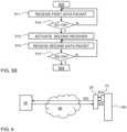
- FIG. 6is a schematic view of an example data management system in accordance with embodiments.
- the data management systemcomprises one or more electronic tags 10 (one shown), which may be attached to a respective device 100 as shown, one or more PEDs 20 (one shown), and one or more computer devices 30 (one shown).
- the PED 20is operable to communicate with the computer device 30 over a network 40 by use of a communication device (cf. 25 in FIG. 4 ).
- the PED 20receives ID1 and ID2 from the tag 10.
- the PED 20may perform any of a plurality of action upon receipt of ID2. Such actions may include providing a confirmation message to the user via a feedback device (cf. 24 in FIG.
- the PED 20may wait for the computer device 30 to return a confirmation.
- the computer device 30may also return one or more files, which may then be executed or opened by the PED 20.
- the filesmay, for example, include one or more media files comprising any one or pictures, music, audios, videos, documents etc.
- tags 10may be attached to exercise devices 100 in a gym environment, and the data management system may be configured to collect workout data associated with exercise devices and users/PEDs.
- tags 10may be attached to devices 100 in an office environment, and the data management system may be configured to collect information about the need for service or maintenance of the respective device.
- tags 10may be attached to labels or signs at a museum, monument, historical site or other attraction, to allow the user of a PED 20 to be presented with further information on the PED 20 by docking the PED 20 to the tag 10.
- tags 10may be arranged at entrance points to a confined space such as a building, an office space, etc., to allow the user to check in to the confined space by performing the docking operation.
- checking inmay comprise the PED 20 transmitting ID2, or part thereof, together with an identifier of the PED 20 or its user to the computer device 30.
- checking inmay comprise validating a ticket purchased by the user and stored in the PED 20 or in the computer device 30.
- tags 10may be arranged on signs with names and/or photographs of staff, to allow the user to be presented with further information about, for example, the skills or experience of a specific individual by performing the docking operation on one of the tags.
- the staffmay be personal trainers in a gym environment.
Landscapes
- Engineering & Computer Science (AREA)
- Physics & Mathematics (AREA)
- Health & Medical Sciences (AREA)
- Toxicology (AREA)
- Computer Networks & Wireless Communication (AREA)
- Theoretical Computer Science (AREA)
- General Physics & Mathematics (AREA)
- Artificial Intelligence (AREA)
- Computer Vision & Pattern Recognition (AREA)
- Signal Processing (AREA)
- General Health & Medical Sciences (AREA)
- Electromagnetism (AREA)
- Computer Security & Cryptography (AREA)
- Computer Hardware Design (AREA)
- Microelectronics & Electronic Packaging (AREA)
- Mobile Radio Communication Systems (AREA)
Description
- The present disclosure relates generally to electronic tags configured for short-range wireless transfer of an identifier to a receiving electronic device, as well as data management by use of such electronic tags.
- Electronic tags are well-known and may be used for various identification purposes. The electronic tag may be based on radio-frequency identification (RFID) technology, in which radio waves are used to automatically identify electronic tags attached to objects. Such RFID tags are read by dedicated RFID readers. The RFID reader sends an interrogating signal to the tag, and the tag responds with its unique information. A specialized subset within the family of RFID technology is denoted near-field communication (NFC). Specifically, NFC is a branch of high-frequency (HF) RFID. NFC is designed to be a secure form of data exchange.
- An alternative to using RFID technology is disclosed in
US10699177 - One shortcoming of
US 10699177 - The prior art comprises electronic tags that have both an RFID component and a Bluetooth component.
US2003/0104848 discloses a hybrid tag which is awakened by presence of a pre-determined intensity RF signal from an RFID interrogator and is operated, based on demodulated data, to communicate by either RFID communication or by Bluetooth communication.US2012/0007712 discloses an electronic tag which activates its Bluetooth transceiver when its RFID transceiver receives a low-frequency start signal, to thereby initiate encrypted communication over Bluetooth.US9864882 US2002/0126013 discloses a reader device that comprises an RFID radio interface and a Bluetooth radio interface to enable location determination of both RFID tags and Bluetooth devices.- It is an objective to at least partly overcome one or more limitations of the prior art.
- One objective is to enable a user device to automatically and wirelessly receive an identifier from an electronic tag.
- One objective is to expand the available identifier systems that may be used for assigning identifiers to electronic tags, for example for use in a data management system.
- The invention is defined by the independent claims, embodiments thereof being defined by the dependent claims.
- According to some aspects of the present disclosure, by combining Bluetooth and RFID transmissions, size limitations of Bluetooth transmissions are overcome and automatic transfer of an identifier from an electronic tag to a portable device is enabled. The available space for the identifier is increased by including the identifier in the RFID transmission (second data packet), and automatic operation may be achieved by automatically activating an RFID receiver in the portable device upon receipt of a Bluetooth transmission (first data packet).
- Still other objectives, aspects and technical effects, as well as embodiments and features will appear from the following detailed description, from the attached claims as well as from the drawings.
- Embodiments will now be described in more detail with reference to the accompanying schematic drawings.
FIG. 1 illustrates an example electronic tag that separately transmits first and second data packets for receipt by an example user equipment.FIGS 2A-2C illustrates an example docking operation of user equipment onto an electronic tag.FIG. 3 is a block diagram of an example electronic tag.FIG. 4 is a block diagram of example user equipment.FIGS 5A-5B are flow charts of example methods of operating user equipment based on data from an electronic tag.FIG. 6 illustrates data flow in an example data management system comprising user equipment and an electronic tag.- Embodiments will now be described more fully hereinafter with reference to the accompanying drawings, in which some, but not all, embodiments are shown. Indeed, the subject of the present disclosure may be embodied in many different forms and should not be construed as limited to the embodiments set forth herein; rather, these embodiments are provided so that this disclosure may satisfy applicable legal requirements.
- It will be understood that, where possible, any of the advantages, features, functions, devices, and/or operational aspects of any of the embodiments described and/or contemplated herein may be included in any of the other embodiments described and/or contemplated herein, and/or vice versa. In addition, where possible, any terms expressed in the singular form herein are meant to also include the plural form and/or vice versa, unless explicitly stated otherwise. As used herein, "at least one" shall mean "one or more" and these phrases are intended to be interchangeable. Accordingly, the terms "a" and/or "an" shall mean "at least one" or "one or more," even though the phrase "one or more" or "at least one" is also used herein. As used herein, except where the context requires otherwise owing to express language or necessary implication, the word "comprise" or variations such as "comprises" or "comprising" is used in an inclusive sense, that is, to specify the presence of the stated features but not to preclude the presence or addition of further features in various embodiments. The term "and/or" comprises any and all combinations of one or more of the associated listed elements.
- It will furthermore be understood that although the terms first, second, etc. may be used herein to describe various elements, these elements should not be limited by these terms. These terms are only used to distinguish one element from another. For example, a first element could be termed a second element, and, similarly, a second element could be termed a first element, without departing the scope of the present disclosure.
- Well-known functions or constructions may not be described in detail for brevity and/or clarity. Unless otherwise defined, all terms (including technical and scientific terms) used herein have the same meaning as commonly understood by one of ordinary skill in the art to which this disclosure belongs.
- Like numerals refer to like elements throughout.
- Before describing embodiments in more detail, a few definitions will be given.
- As used herein, "electronic tag" refers to any device capable of being attached to another device and containing electronic circuitry for wireless transmission of data.
- As used herein, "transmitter" refers to any device capable of transmitting data. Thus, the term "transmitter" also encompasses a transceiver.
- As used herein, "receiver" refers to any device capable of receiving data. Thus, the term "receiver" also encompasses a transceiver.
- As used herein, Bluetooth or "BT" refers to wireless communication in compliance with a Bluetooth SIG standard in any version. For the avoidance of doubt, Bluetooth also includes the Bluetooth Low Energy standard, also known as Bluetooth LE and Bluetooth Smart.
- As used herein, RFID (Radio-Frequency IDentification) refers to the established and well-known technique of using electromagnetic or electrostatic coupling in the radio frequency portion of the electromagnetic spectrum to transfer an identifier from a first device (RFID tag) to a second device (RFID reader). The RFID reader, denoted "receiver" herein, uses radio frequency waves to transmit an interrogating signal that activates the RFID tag. Once activated, the RFID tag sends a return wave back to the RFID reader, where it is translated into data, for example an identifier of the RFID tag. The RFID tag comprises a transponder, denoted "transmitter" herein, which is configured to generate the return wave. The RFID tag may be active or passive. An active RFID tag has its own power source, often a battery. A passive RFID tag is powered by the interrogating signal from the RFID reader, by the interrogating signal inducing an electrical current in the transponder of the RFID tag.
- As used herein, NFC (Near-Field Communication) refers to a subset of RFID technology, specifically High-Frequency (HF) RFID. NFC is, for example, standardized in ECMA-340 and ISO/IEC 18092 and in a plurality of standards defined by the NFC Forum. NFC has a maximum transmission range of about 20 cm, but the transmission range is typically a few cm in practice. By analogy with RFID, data may be transferred from a first device ("NFC tag") to a second device ("NFC reader").
- As used herein, "transmission range" of a transmitter refers to the reach of a signal transmitted by the transmitter, where the reach may be given by the average distance at which the strength of the signal equals a detection threshold for reliable detection by a receiver.
- As used herein, "portable electronic device" ("PED") is synonymous with "user equipment" ("UE") and comprises any electronic device which is capable of being carried, held or worn by a user. Such portable electronic devices include handheld devices, such as mobile phones, smartphones, tablets, laptops, gaming consoles, etc., as well as wearable computers ("wearables"), such as smart glasses, smart watches, headsets, badges, bracelets, fitness trackers, etc. The portable electronic devices may be generic devices capable of performing different tasks, for example by executing different application programs, or specialized devices tailored to perform a single task.
- As used herein, "proximity sensor" refers to any device capable of detecting presence of an object within a certain distance, without requiring physical contact with the object. As used herein, a region in which the proximity sensor is capable of detecting presence of objects is denoted "detection zone". The proximity sensor may implement any conceivable technique for detecting the object, for example by emitting a beam or field of electromagnetic radiation (including infrared radiation) or sound waves (including ultrasound) and analyzing the field or a return signal. The proximity sensor may be configured to detect all objects within the detection zone (indiscriminate detection), or only objects having a specific property (discriminate detection).
- Embodiments described in the following are directed to ensuring proper "docking" of a PED to an electronic tag, with the docking involving a wireless transfer of a tag identifier (tag ID) from the electronic tag to the PED when the PED is brought in sufficient proximity of the electronic tag. Such a docking operation constitutes an intuitive and user-friendly way for a user to interact with electronic tags and may be implemented to trigger, based on the tag ID, any dedicated function in the PED and/or in a computer device connected to the PED.
- The embodiments will be motivated with reference to the proposed data collection system in
US10699177 US 10699177 US 10699177 FIG. 1 illustrates an example combination of anelectronic tag 10 and aPED 20 in accordance with an embodiment. Thetag 10 comprises aBLE transmitter 11 and anNFC transmitter 12. TheBLE transmitter 11 is operable to transmit a first signal S1 comprising data packets ("BLE packets") that include a first identifier ID1, for example in compliance with the iBeacon protocol. TheNFC transmitter 12 is operable to transmit a second signal S2 comprising data packets ("NFC packets") that include a second identifier ID2. ThePED 20 comprises aBLE receiver 21, anNFC receiver 22 and acontrol unit 23 which is connected to thereceivers control unit 23 comprises logic for controlling the operation of thereceiver tag 10 enables thePED 20 to be designed to overcome the above-described obstacles when using iOS. By transmitting the tag ID as ID2, that is in the NFC packets, the limitation on size of the tag ID is overcome and ID2 may uniquely identify a much larger number of individual tags. By transmitting ID1 in the BLE packets, thePED 20 may be configured to automatically simulate a user activation of theNFC receiver 22 to overcome the need for user intervention on thePED 20 to manually activate theNFC receiver 22. It is realized that ID1 may be a generic identifier that may be transmitted by several or even alltags 10 to trigger thePED 20 to activate itsNFC receiver 22 and that the available space for ID1 in BLE packets, even those complying with the iBeacon protocol, is sufficient to accommodate such a generic identifier.- In some embodiments, ID2 may comprise a MAC address, which has been assigned to the respective tag. MAC addresses are given by a 48-bit address space (EUI-48) or a 64-bit address space (EUI-64). To represent a MAC address, ID2 may be required to comprise 48 or 64 bits, which if not possible with BLE packets, is enabled by the
tag 10 inFIG. 1 . FIGS 2A-2C illustrate a docking operation of thePED 20 in which thePED 20 is brought in proximity of thetag 10, which is attached to adevice 100. Thedevice 100 may, for example, be an exercise device as disclosed in aforesaidUS10699177 FIGS 2A-2C , filled squares indicate activated transmitters/receivers and open squares indicate disabled transmitters/receivers.FIG. 2A presumes that thetag 10 comprises aproximity detector 16 with a detection zone DZ and that the default state of thetag 10 is a low-power state in which bothtransmitters tag 10. To minimize the need for user intervention during the docking operation, thePED 20 may be operated, by default or through user selection, with itsBLE receiver 21 activated to intercept BLE packets. Thus, inFIG. 2A , with thePED 20 being located outside the detection zone DZ, thetag 10 is in its low-power state and does not transmit any signals. Depending on implementation, the detection zone DZ may extend to a distance of 1-100 cm from thetag 10, or even longer. InFIG. 2B , thePED 20 is moved into the detection zone DZ, as indicated by an arrow, causing thetag 10 to activate itsBLE transmitter 11 to transmit the first signal S1 with ID1. When the antenna of theBLE receiver 21 is within the transmission range of theBLE transmitter 11, theBLE receiver 21 intercepts S1. ThePED 20 extracts and evaluates ID1. Depending on ID1, thePED 20 may then activate theNFC receiver 22, as indicated inFIG. 2C . TheNFC receiver 22 thereby transmits an interrogation signal. TheNFC transmitter 12, on the other hand, is inherently operable to transmit S2 at all times and, as shown inFIG. 2C , is automatically activated to transmit S2 when receiving the interrogation signal from theNFC receiver 22. ThePED 20 then extracts and evaluates ID2, and the docking operation is complete. Subject to the evaluation, thePED 20 may perform a predefined action, as exemplified further below.- Reverting to
FIG. 1 , it may be advantageous to set the transmission range TR1 of theBLE transmitter 11 in relation to the transmission range TR2 of theNFC transmitter 12. In practice, TR2 is typically less than 10 cm, and often less than 5 cm. On the other hand, TR1 may be several hundreds of meters for a BLE transmitter. It is understood fromFIGS 2A-2C that if TR1 is too large, for example much larger than TR2, theNFC receiver 22 may be activated even if there is no intention of the user of thePED 20 to perform a docking operation. This will increase the computational load on thePED 20 and increase its power consumption. In some embodiments, thetag 10 is configured with a transmission range TR1 of the same order of magnitude as the transmission range TR2. This may be achieved by controlling theBLE transmitter 11 to reduce the power of the first signal S1. In some embodiments, TR1 is set to be less than about 20, 15, 10 or 5 times TR2. In a practical setting, it may be desirable for both TR1 and TR2 to be less than about 60, 50, 40, 30, 20, or 10 centimeters. For smaller TR1 and TR2, the docking operation becomes more spatially and temporally precise. It may also be noted that reducing the output power of theBLE transmitter 11 has the additional benefit of reducing the power consumption of thetag 10. FIG. 3 is a block diagram of an exampleelectronic tag 10 in accordance with an embodiment. The components illustrated inFIG. 3 may be located in a housing which is indicated by dashed lines. In the illustrated example, thetag 10 comprises a Bluetooth (BT) module 11', which includes theBLE transmitter 11 and, for example, an antenna (not shown). The BT module 11' may, but need not, also be or include a BLE receiver (not shown). Thetag 10 further comprises an NFC module 12', which includes theNFC transmitter 12, for example implemented as a passive or active NFC transponder. Thetag 10 further comprises acontrol unit 13, which is configured to implement logic for controlling thetag 10. In the illustrated example, thecontrol unit 13 comprises a combination of aprocessor 13A and amemory 13B. Thememory 13B may store program instructions for execution by theprocessor 13A for implementing the operation of thecontrol unit 13. The program instructions may be supplied to theprocessor 13A on a computer-readable medium, which may be a tangible (non-transitory) product (for example, magnetic medium, optical disk, read-only memory, flash memory, etc.) or a propagating signal. Theprocessor 13A may be a generic processor, for example a microprocessor, microcontroller, CPU, DSP (digital signal processor), GPU (graphics processing unit), etc., or a specialized processor, such as an ASIC (application specific integrated circuit) or an FPGA (field programmable gate array), or any combination thereof. Thememory 13B may include volatile and/or non-volatile memory such as read only memory (ROM), random access memory (RAM) or flash memory.- The
control unit 13 is electrically connected by wiring 14 to the BT module 11' and is operable to cause the BT module 11' to transmit signal S1. Thecontrol unit 13 may also, for example if theNFC transmitter 12 is of the active type, be electrically connected by wiring 15 to the NFC module 12'. Depending on implementation, the identifiers ID1, ID2 may be stored in the respective module 11', 12' or in thememory 13B of thecontrol unit 13. - In the illustrated example, the
tag 10 further comprises a proximity detector orsensor 16, which is electrically connected by wiring 17 to thecontrol unit 13. Thecontrol unit 13 may be configured to cause the BT module 11' to activate theBLE transmitter 11, whenever a signal from theproximity sensor 16 indicate an object within the detection zone (cf. DZ inFIG. 2A ). While the provision of theproximity sensor 16 may reduce the power consumption of thetag 10, it is conceivable to omit theproximity sensor 16 and instead configure thetag 10 to repeatedly and continuously transmit the signal S1. Thetag 10 further comprises apower source 18, for example a battery or a fuel cell, for supplying power to thecontrol unit 13 and the BT module 11', and possibly to the NFC module 12' and theproximity sensor 16. FIG. 4 is a block diagram of anexample PED 20 for use in embodiments. ThePED 20 comprises theBLE receiver 21, for example implemented on a BT chip, and theNFC receiver 22, for example implemented as an NFC reader. ThePED 20 further comprises acontrol unit 23, which is configured to implement logic for controlling thePED 20. In the illustrated example, thecontrol unit 23 comprises a combination of aprocessor 23A and amemory 23B. Thememory 23B may store program instructions for execution by theprocessor 23A for implementing the operation of thecontrol unit 23. The program instructions may be supplied to theprocessor 23A on a computer-readable medium, which may be a tangible (non-transitory) product (for example magnetic medium, optical disk, read-only memory, flash memory, etc.) or a propagating signal. Theprocessor 23A may be a generic processor, for example a microprocessor, microcontroller, CPU, DSP (digital signal processor), GPU (graphics processing unit), etc., or a specialized processor, such as an ASIC (application specific integrated circuit) or an FPGA (field programmable gate array), or any combination thereof. Thememory 23B may include volatile and/or non-volatile memory such as read only memory (ROM), random access memory (RAM) or flash memory. In the illustrated example, thePED 20 further comprises afeedback unit 24 for providing one or more of audible, visible or tactile feedback to the user. Such afeedback unit 24 may comprise one or more of a speaker, a buzzer, a vibrator, a display, a touch screen, an indicator lamp, etc. As shown, thePED 20 may also comprise acommunication device 25 for wireless or wired data transfer over a network, such as a WAN, LAN, PAN or any combination thereof.- Although embodiments have been described with reference to BLE and NFC, the present disclosure is not limited to these specific wireless technologies. Corresponding technical advantages may be achieved for other combinations of wireless short-range technologies, including but not limited to a combination of any Bluetooth technology with any RFID technology. In further examples, any one of the
transmitters tag 10, and correspondingly thereceivers PED 20, may be configured for communication by Zigbee, Z-wave, ambient backscatter communication (ABC), WiFi, etc. Thus, in some embodiments, both of thetransmitters control unit 13 to transmit the respective signal S1, S2. To limit the power consumption of thetag 10, thetransmitter 12 may be activated to transmit S2 concurrent with or subsequent to thetransmitter 11 being activated to transmit S1. - With further reference to
FIG. 1 , in a generic embodiment, theelectronic tag 10 comprises afirst transmitter 11 configured in accordance with a first short-range wireless technology and operable to transmit first data packets comprising a first identifier ID1, and asecond transmitter 12 configured in accordance with a second short-range wireless technology, which is different from the first short-range wireless technology. Thesecond transmitter 21 is operable to transmit second data packets comprising a second identifier ID2, which is different from the first identifier ID1 Similarly, in a generic embodiment, thePED 20 comprises afirst receiver 21 configured to receive one or more of the first data packets transmitted by theelectronic tag 10, and asecond receiver 22 configured to receive one or more of the second data packets transmitted by theelectronic tag 10. The skilled person understands that the embodiments and examples described in the foregoing are equally applicable for other combinations of first and second short-range wireless technologies. FIG. 5A is a flowchart of amethod 500 for operating thePED 20 in accordance with an embodiment. Themethod 500 may be performed by the control unit 23 (FIG. 1 ) and may be applied irrespective of the combination of wireless short-range technologies. The method will therefore be described with respect to the above-mentioned generic embodiment. Instep 501, thefirst receiver 21 on thePED 20 is operated to receive one or more first data packets transmitted by thefirst transmitter 11 in thetag 10. Instep 502, thePED 20 is operated to selectively activate thesecond receiver 22. The term "selectively activate" may imply that thesecond receiver 22 is activated provided that at least one first data packet is accepted by a validation process in thePED 20. Instep 503, which is performed when thePED 20 has received one or more second data packets through thesecond receiver 22, thePED 20 is operated to perform a predefined action. The predefined action may be selected based on ID2 in the second data packet(s) or may be a default action performed by thePED 20 whenever ID2 is received. Instep 504, thePED 20 may deactivate thesecond receiver 22. Step 504 may be performed when thePED 20 has received the second data packet(s) and/or has performed the predefined action, or after expiry of a predefined time period ("time-out period") from the activation of thesecond receiver 22 instep 502.FIG. 5B is a flowchart ofstep 502 in accordance with an embodiment. Instep 511, thefirst receiver 21 receives a first data packet. Instep 512, thePED 20 processes the first data packet to extract ID1 and then evaluates ID1 in relation to a first validation criterion. In one example, the first validation criterion may stipulate that ID1 should have a specific value or fall within a specific range of values. In another example, the first validation criterion may stipulate that a first evaluation function, when operated on ID1, should return a value in a specific range. The first validation criterion may further stipulate that the strength of signal S1, when the first data packet is received, should exceed a threshold value. If the first validation criterion is not satisfied, step 512 may proceed to wait for another first data packet. Otherwise, step 512 may proceed to step 513, in which thePED 20 activates thesecond receiver 22. Instep 514, thesecond receiver 22 receives a second data packet. Instep 515, thePED 20 processes the second data packet to extract ID2 and then evaluates ID2 in relation to a second validation criterion. The second validation criterion may stipulate that ID2 should fall within a specific range of values and/or that a second evaluation function, when operated on ID2, should return a value in a specific range. If the second validation criterion is not satisfied, step 515 may proceed to wait for another second data packet. Otherwise, step 512 may proceed to step 503. In a variant, the second validation bystep 515 is omitted and all second data packets are presumed to contain a valid ID2.FIG. 6 is a schematic view of an example data management system in accordance with embodiments. The data management system comprises one or more electronic tags 10 (one shown), which may be attached to arespective device 100 as shown, one or more PEDs 20 (one shown), and one or more computer devices 30 (one shown). ThePED 20 is operable to communicate with thecomputer device 30 over anetwork 40 by use of a communication device (cf. 25 inFIG. 4 ). As described in the foregoing, thePED 20 receives ID1 and ID2 from thetag 10. Depending on implementation, thePED 20 may perform any of a plurality of action upon receipt of ID2. Such actions may include providing a confirmation message to the user via a feedback device (cf. 24 inFIG. 4 ), store ID2 or part thereof in internal memory (cf. 23B inFIG. 4 ), open or execute one or more files stored in internal memory, open a specific web page in a browser on thePED 20, or transmit ID2 or part thereof to thecomputer device 30 over thenetwork 40. After transmitting ID2 or part thereof, thePED 20 may wait for thecomputer device 30 to return a confirmation. Thecomputer device 30 may also return one or more files, which may then be executed or opened by thePED 20. The files may, for example, include one or more media files comprising any one or pictures, music, audios, videos, documents etc.- The data management system in
FIG. 6 may be applied in a variety of use cases. In one example, described in aforesaidUS 10699177 devices 100 in a gym environment, and the data management system may be configured to collect workout data associated with exercise devices and users/PEDs. In another example, also described in aforesaidUS 10699177 devices 100 in an office environment, and the data management system may be configured to collect information about the need for service or maintenance of the respective device. In another example, tags 10 may be attached to labels or signs at a museum, monument, historical site or other attraction, to allow the user of aPED 20 to be presented with further information on thePED 20 by docking thePED 20 to thetag 10. In another example, tags 10 may be arranged at entrance points to a confined space such as a building, an office space, etc., to allow the user to check in to the confined space by performing the docking operation. In one example, checking in may comprise thePED 20 transmitting ID2, or part thereof, together with an identifier of thePED 20 or its user to thecomputer device 30. In another example, checking in may comprise validating a ticket purchased by the user and stored in thePED 20 or in thecomputer device 30. In a service environment, tags 10 may be arranged on signs with names and/or photographs of staff, to allow the user to be presented with further information about, for example, the skills or experience of a specific individual by performing the docking operation on one of the tags. For example, the staff may be personal trainers in a gym environment. - While the subject of the present disclosure has been described in connection with what is presently considered to be the most practical embodiments, it is to be understood that the subject of the present disclosure is not to be limited to the disclosed embodiments, but on the contrary, is intended to cover various modifications and equivalent arrangements.
- Further, while operations are depicted in the drawings in a particular order, this should not be understood as requiring that such operations be performed in the particular order shown or in sequential order, or that all illustrated operations be performed, to achieve desirable results.
Claims (14)
- An electronic tag, comprising:a Bluetooth transmitter (11) which is operable to transmit first data packets;an RFID transmitter (12) which is operable to transmit second data packets;wherein the first data packets comprise a first identifier (ID1) and the second data packets comprise a second identifier (ID2), andwherein the first identifier (ID1) is smaller in size, given by number of bits, than the second identifier (ID2),characterized in that the second identifier (ID2) is not included in the first data packets.
- The electronic tag of claim 1, wherein the first identifier (ID1) is a generic identifier for a plurality of electronic tags, and the second identifier (ID1) is a dedicated identifier for the electronic tag.
- The electronic tag of any preceding claim, wherein the second identifier (ID2) comprises a MAC address.
- The electronic tag of any preceding claim, wherein the Bluetooth transmitter (11) has a first wireless transmission range (TR1), and the RFID transmitter has a second wireless transmission range (TR2), and wherein the first wireless transmission range (TR1) is less than 20 times the second wireless transmission range (TR2).
- The electronic tag of claim 4, wherein the first and second wireless transmission ranges (TR1, TR2) are less than 60 centimeters.
- The electronic tag of any preceding claim, wherein the RFID transmitter (12) is operated to transmit the second data packets concurrent with or subsequent to the electronic tag operating the Bluetooth transmitter (11) to transmit the first data packets.
- The electronic tag of any preceding claim, further comprising a proximity sensor (18) configured to detect presence of an object within a detection zone (DZ), wherein the electronic tag comprises a control unit (13), which is connected to the proximity sensor (18) and the Bluetooth transmitter (11) and is configured to selectively, when the proximity sensor (18) detects presence of the object within the detection zone (DZ), activate the Bluetooth transmitter (11) to transmit the first data packages.
- A portable electronic device, comprising:a Bluetooth receiver (21) which is operable to receive a first data packet transmitted by an electronic tag (10);an RFID receiver (22) which is operable to receive a second data packet transmitted by the electronic tag (10); anda control unit (23) connected to the Bluetooth receiver (21) and the RFID receiver (22)characterized in that the control unit (23) is configured to selectively activate the RFID receiver (22) upon receiving the first data packet, wherein the control unit (23) is configured to, upon said receiving the first data packet, process the first data packet to extract a first identifier (ID1), and determine, based on the first identifier (ID1), whether to activate the RFID receiver (22).
- The portable electronic device of claim 8, wherein the control unit (23) is configured to deactivate the RFID receiver (22) at a time period after activation and/or when the RFID receiver (22) has received the second data packet.
- The portable electronic device of claim 8 or 9, wherein the control unit (23) is configured to, upon receiving the second data packet, perform a predefined action as a function of the second data packet.
- The portable electronic device of claim 10, wherein the control unit (23) is configured to, upon receiving the second data packet, process the second data packet to extract a second identifier (ID2) and perform the predefined action as a function of the second identifier (ID2).
- The portable electronic device of claim 11, wherein the predefined action comprises one or more of: operating a feedback device (24) on the portable electronic device to present content associated with the second identifier (ID2), or operating a communication device (25) to transmit at least part of the second identifier (ID2) to a computer system (30) over a network (40).
- A system comprising the portable electronic device of any one of claims 8-12, and the electronic tag (10) of any one of claims 1-7.
- A method of controlling a portable electronic device, comprising:operating (501) a Bluetooth receiver on the portable electronic device to receive first data packets transmitted by an electronic tag in accordance with a first wireless short-range communication protocol;characterized by operating (502) the portable electronic device, upon receipt of at least one of the first data packets, to selectively activate an RFID receiver on the portable electronic device for receipt of second data packets transmitted by the electronic tag in accordance with a second wireless short-range communication protocol;and operating (503) the portable electronic device to perform, upon receipt of at least one of the second data packets, a predefined action as a function of the at least one of the second data packets, wherein the portable electronic device, upon said receipt of said at least one of the first data packets, is operated to process said at least one of the first data packets to extract a first identifier, and determine, based on the first identifier, whether to activate the RFID receiver.
Applications Claiming Priority (1)
| Application Number | Priority Date | Filing Date | Title |
|---|---|---|---|
| SE2050864 | 2020-07-09 |
Publications (2)
| Publication Number | Publication Date |
|---|---|
| EP3937062A1 EP3937062A1 (en) | 2022-01-12 |
| EP3937062B1true EP3937062B1 (en) | 2024-04-10 |
Family
ID=76076229
Family Applications (1)
| Application Number | Title | Priority Date | Filing Date |
|---|---|---|---|
| EP21175442.9AActiveEP3937062B1 (en) | 2020-07-09 | 2021-05-21 | Electronic tag for data management |
Country Status (2)
| Country | Link |
|---|---|
| US (1) | US20220014892A1 (en) |
| EP (1) | EP3937062B1 (en) |
Families Citing this family (3)
| Publication number | Priority date | Publication date | Assignee | Title |
|---|---|---|---|---|
| US11847519B2 (en)* | 2022-05-16 | 2023-12-19 | Bluicity Inc. | System and method for tracking tags over bluetooth low energy |
| US12340641B2 (en)* | 2022-03-10 | 2025-06-24 | Honeywell International Inc. | System and method for activating lockbox when authenticating device is in range |
| US20240346268A1 (en) | 2023-04-13 | 2024-10-17 | Bruce Walter Wilkinson | Session Control Broadcaster for RFID Systems |
Family Cites Families (8)
| Publication number | Priority date | Publication date | Assignee | Title |
|---|---|---|---|---|
| US6717516B2 (en)* | 2001-03-08 | 2004-04-06 | Symbol Technologies, Inc. | Hybrid bluetooth/RFID based real time location tracking |
| US7215976B2 (en)* | 2001-11-30 | 2007-05-08 | Symbol Technologies, Inc. | RFID device, system and method of operation including a hybrid backscatter-based RFID tag protocol compatible with RFID, bluetooth and/or IEEE 802.11x infrastructure |
| US20120007712A1 (en)* | 2010-07-09 | 2012-01-12 | Deutron Electronics Corp | Non-contact control method and device |
| US10209946B2 (en)* | 2012-08-23 | 2019-02-19 | Red Hat, Inc. | Augmented reality personal identification |
| US9864882B1 (en)* | 2013-07-19 | 2018-01-09 | Geotoll, Inc. | Energy harvesting for battery-less RFID tag devices with internal transmitters |
| US9700669B2 (en)* | 2015-04-16 | 2017-07-11 | Flowonix Medical Incorporated | Patient programmer for implantable drug delivery device |
| JP6801375B2 (en)* | 2016-11-01 | 2020-12-16 | セイコーエプソン株式会社 | Wireless communication device, its control method and control program |
| EP3373190B1 (en) | 2017-03-10 | 2021-08-18 | Sony Group Corporation | Electronic tag |
- 2021
- 2021-05-21EPEP21175442.9Apatent/EP3937062B1/enactiveActive
- 2021-05-23USUS17/327,722patent/US20220014892A1/ennot_activeAbandoned
Also Published As
| Publication number | Publication date |
|---|---|
| US20220014892A1 (en) | 2022-01-13 |
| EP3937062A1 (en) | 2022-01-12 |
Similar Documents
| Publication | Publication Date | Title |
|---|---|---|
| EP3937062B1 (en) | Electronic tag for data management | |
| CN107257979B (en) | Method and apparatus for energy harvesting from proximity coupling devices | |
| EP2770782B1 (en) | Wireless data communication | |
| US9881190B2 (en) | Detector logic and radio identification device and method for enhancing terminal operations | |
| US20140229246A1 (en) | RFID Frequency Translator | |
| US9351322B2 (en) | Wireless communication link establishment | |
| JP2016042693A (en) | Method for detecting manipulation by user of device provided with communication tag, corresponding computer program product, user terminal, device and system | |
| JP4090808B2 (en) | Method and system for controlling proximity transactions | |
| EP3058792B1 (en) | Wireless protocol message conversion method and corresponding device | |
| US9615196B2 (en) | NFC device configuration after device power up | |
| US10482458B2 (en) | User equipment, service providing device, payment system comprising the same, control method thereof and non-transitory computer-readable storage medium storing computer program recorded thereon | |
| KR100857825B1 (en) | System and method for automatically running an application and mobile communication terminal therefor | |
| KR101281832B1 (en) | System for notifying location of missing dog | |
| US9697396B2 (en) | Interactive processing method and device and electronic apparatus | |
| CN105099514A (en) | Method for discovering multiple NFC-B devices by NFC-B reader and corresponding NFC-B reader | |
| KR20140120931A (en) | Methods and apparatus for improving resolution among devices with different size nfc identifiers | |
| KR20120068646A (en) | Id recognition method and device using bluetooth feature in smart phone | |
| EP2518982A1 (en) | Mobile device, transponder, near field communication system and method for configuring a mobile device | |
| Proehl et al. | An introduction to near field communications | |
| KR101839942B1 (en) | Mobile Pay Methode Using BLE | |
| CN102136855B (en) | System and method for searching mobile phone | |
| JP2008182579A (en) | Radio authentication system, and entry/exit control system using the same | |
| KR102718721B1 (en) | Wireless tag apparatus | |
| KR101717231B1 (en) | Anti-collision method considering p2p communication between nfc devices in coexistence with rfid system | |
| KR20160060445A (en) | Method for user location recognition by identity confirmation card, method for beacon signal generation by identity confirmation card and appilcation for identity confirmation card or server |
Legal Events
| Date | Code | Title | Description |
|---|---|---|---|
| PUAI | Public reference made under article 153(3) epc to a published international application that has entered the european phase | Free format text:ORIGINAL CODE: 0009012 | |
| STAA | Information on the status of an ep patent application or granted ep patent | Free format text:STATUS: THE APPLICATION HAS BEEN PUBLISHED | |
| AK | Designated contracting states | Kind code of ref document:A1 Designated state(s):AL AT BE BG CH CY CZ DE DK EE ES FI FR GB GR HR HU IE IS IT LI LT LU LV MC MK MT NL NO PL PT RO RS SE SI SK SM TR | |
| B565 | Issuance of search results under rule 164(2) epc | Effective date:20211029 | |
| STAA | Information on the status of an ep patent application or granted ep patent | Free format text:STATUS: REQUEST FOR EXAMINATION WAS MADE | |
| 17P | Request for examination filed | Effective date:20220609 | |
| RBV | Designated contracting states (corrected) | Designated state(s):AL AT BE BG CH CY CZ DE DK EE ES FI FR GB GR HR HU IE IS IT LI LT LU LV MC MK MT NL NO PL PT RO RS SE SI SK SM TR | |
| STAA | Information on the status of an ep patent application or granted ep patent | Free format text:STATUS: EXAMINATION IS IN PROGRESS | |
| 17Q | First examination report despatched | Effective date:20221209 | |
| GRAP | Despatch of communication of intention to grant a patent | Free format text:ORIGINAL CODE: EPIDOSNIGR1 | |
| STAA | Information on the status of an ep patent application or granted ep patent | Free format text:STATUS: GRANT OF PATENT IS INTENDED | |
| INTG | Intention to grant announced | Effective date:20231006 | |
| GRAS | Grant fee paid | Free format text:ORIGINAL CODE: EPIDOSNIGR3 | |
| GRAA | (expected) grant | Free format text:ORIGINAL CODE: 0009210 | |
| STAA | Information on the status of an ep patent application or granted ep patent | Free format text:STATUS: THE PATENT HAS BEEN GRANTED | |
| RAP1 | Party data changed (applicant data changed or rights of an application transferred) | Owner name:LUMOS HOLDINGS US ACQUISITION CO. | |
| AK | Designated contracting states | Kind code of ref document:B1 Designated state(s):AL AT BE BG CH CY CZ DE DK EE ES FI FR GB GR HR HU IE IS IT LI LT LU LV MC MK MT NL NO PL PT RO RS SE SI SK SM TR | |
| REG | Reference to a national code | Ref country code:GB Ref legal event code:FG4D | |
| REG | Reference to a national code | Ref country code:CH Ref legal event code:EP | |
| REG | Reference to a national code | Ref country code:DE Ref legal event code:R096 Ref document number:602021011487 Country of ref document:DE | |
| REG | Reference to a national code | Ref country code:IE Ref legal event code:FG4D | |
| P01 | Opt-out of the competence of the unified patent court (upc) registered | Effective date:20240517 | |
| RAP4 | Party data changed (patent owner data changed or rights of a patent transferred) | Owner name:LUMOS HOLDINGS US ACQUISITION CO. | |
| REG | Reference to a national code | Ref country code:LT Ref legal event code:MG9D | |
| REG | Reference to a national code | Ref country code:NL Ref legal event code:MP Effective date:20240410 | |
| REG | Reference to a national code | Ref country code:AT Ref legal event code:MK05 Ref document number:1675644 Country of ref document:AT Kind code of ref document:T Effective date:20240410 | |
| PG25 | Lapsed in a contracting state [announced via postgrant information from national office to epo] | Ref country code:NL Free format text:LAPSE BECAUSE OF FAILURE TO SUBMIT A TRANSLATION OF THE DESCRIPTION OR TO PAY THE FEE WITHIN THE PRESCRIBED TIME-LIMIT Effective date:20240410 | |
| PG25 | Lapsed in a contracting state [announced via postgrant information from national office to epo] | Ref country code:NL Free format text:LAPSE BECAUSE OF FAILURE TO SUBMIT A TRANSLATION OF THE DESCRIPTION OR TO PAY THE FEE WITHIN THE PRESCRIBED TIME-LIMIT Effective date:20240410 | |
| PG25 | Lapsed in a contracting state [announced via postgrant information from national office to epo] | Ref country code:IS Free format text:LAPSE BECAUSE OF FAILURE TO SUBMIT A TRANSLATION OF THE DESCRIPTION OR TO PAY THE FEE WITHIN THE PRESCRIBED TIME-LIMIT Effective date:20240810 | |
| PG25 | Lapsed in a contracting state [announced via postgrant information from national office to epo] | Ref country code:BG Free format text:LAPSE BECAUSE OF FAILURE TO SUBMIT A TRANSLATION OF THE DESCRIPTION OR TO PAY THE FEE WITHIN THE PRESCRIBED TIME-LIMIT Effective date:20240410 | |
| PG25 | Lapsed in a contracting state [announced via postgrant information from national office to epo] | Ref country code:HR Free format text:LAPSE BECAUSE OF FAILURE TO SUBMIT A TRANSLATION OF THE DESCRIPTION OR TO PAY THE FEE WITHIN THE PRESCRIBED TIME-LIMIT Effective date:20240410 Ref country code:FI Free format text:LAPSE BECAUSE OF FAILURE TO SUBMIT A TRANSLATION OF THE DESCRIPTION OR TO PAY THE FEE WITHIN THE PRESCRIBED TIME-LIMIT Effective date:20240410 | |
| PG25 | Lapsed in a contracting state [announced via postgrant information from national office to epo] | Ref country code:GR Free format text:LAPSE BECAUSE OF FAILURE TO SUBMIT A TRANSLATION OF THE DESCRIPTION OR TO PAY THE FEE WITHIN THE PRESCRIBED TIME-LIMIT Effective date:20240711 | |
| PG25 | Lapsed in a contracting state [announced via postgrant information from national office to epo] | Ref country code:PT Free format text:LAPSE BECAUSE OF FAILURE TO SUBMIT A TRANSLATION OF THE DESCRIPTION OR TO PAY THE FEE WITHIN THE PRESCRIBED TIME-LIMIT Effective date:20240812 | |
| PG25 | Lapsed in a contracting state [announced via postgrant information from national office to epo] | Ref country code:ES Free format text:LAPSE BECAUSE OF FAILURE TO SUBMIT A TRANSLATION OF THE DESCRIPTION OR TO PAY THE FEE WITHIN THE PRESCRIBED TIME-LIMIT Effective date:20240410 | |
| PG25 | Lapsed in a contracting state [announced via postgrant information from national office to epo] | Ref country code:AT Free format text:LAPSE BECAUSE OF FAILURE TO SUBMIT A TRANSLATION OF THE DESCRIPTION OR TO PAY THE FEE WITHIN THE PRESCRIBED TIME-LIMIT Effective date:20240410 | |
| PG25 | Lapsed in a contracting state [announced via postgrant information from national office to epo] | Ref country code:PL Free format text:LAPSE BECAUSE OF FAILURE TO SUBMIT A TRANSLATION OF THE DESCRIPTION OR TO PAY THE FEE WITHIN THE PRESCRIBED TIME-LIMIT Effective date:20240410 | |
| PG25 | Lapsed in a contracting state [announced via postgrant information from national office to epo] | Ref country code:LV Free format text:LAPSE BECAUSE OF FAILURE TO SUBMIT A TRANSLATION OF THE DESCRIPTION OR TO PAY THE FEE WITHIN THE PRESCRIBED TIME-LIMIT Effective date:20240410 | |
| PG25 | Lapsed in a contracting state [announced via postgrant information from national office to epo] | Ref country code:PT Free format text:LAPSE BECAUSE OF FAILURE TO SUBMIT A TRANSLATION OF THE DESCRIPTION OR TO PAY THE FEE WITHIN THE PRESCRIBED TIME-LIMIT Effective date:20240812 Ref country code:PL Free format text:LAPSE BECAUSE OF FAILURE TO SUBMIT A TRANSLATION OF THE DESCRIPTION OR TO PAY THE FEE WITHIN THE PRESCRIBED TIME-LIMIT Effective date:20240410 Ref country code:NO Free format text:LAPSE BECAUSE OF FAILURE TO SUBMIT A TRANSLATION OF THE DESCRIPTION OR TO PAY THE FEE WITHIN THE PRESCRIBED TIME-LIMIT Effective date:20240710 Ref country code:LV Free format text:LAPSE BECAUSE OF FAILURE TO SUBMIT A TRANSLATION OF THE DESCRIPTION OR TO PAY THE FEE WITHIN THE PRESCRIBED TIME-LIMIT Effective date:20240410 Ref country code:IS Free format text:LAPSE BECAUSE OF FAILURE TO SUBMIT A TRANSLATION OF THE DESCRIPTION OR TO PAY THE FEE WITHIN THE PRESCRIBED TIME-LIMIT Effective date:20240810 Ref country code:HR Free format text:LAPSE BECAUSE OF FAILURE TO SUBMIT A TRANSLATION OF THE DESCRIPTION OR TO PAY THE FEE WITHIN THE PRESCRIBED TIME-LIMIT Effective date:20240410 Ref country code:GR Free format text:LAPSE BECAUSE OF FAILURE TO SUBMIT A TRANSLATION OF THE DESCRIPTION OR TO PAY THE FEE WITHIN THE PRESCRIBED TIME-LIMIT Effective date:20240711 Ref country code:FI Free format text:LAPSE BECAUSE OF FAILURE TO SUBMIT A TRANSLATION OF THE DESCRIPTION OR TO PAY THE FEE WITHIN THE PRESCRIBED TIME-LIMIT Effective date:20240410 Ref country code:ES Free format text:LAPSE BECAUSE OF FAILURE TO SUBMIT A TRANSLATION OF THE DESCRIPTION OR TO PAY THE FEE WITHIN THE PRESCRIBED TIME-LIMIT Effective date:20240410 Ref country code:BG Free format text:LAPSE BECAUSE OF FAILURE TO SUBMIT A TRANSLATION OF THE DESCRIPTION OR TO PAY THE FEE WITHIN THE PRESCRIBED TIME-LIMIT Effective date:20240410 Ref country code:AT Free format text:LAPSE BECAUSE OF FAILURE TO SUBMIT A TRANSLATION OF THE DESCRIPTION OR TO PAY THE FEE WITHIN THE PRESCRIBED TIME-LIMIT Effective date:20240410 Ref country code:RS Free format text:LAPSE BECAUSE OF FAILURE TO SUBMIT A TRANSLATION OF THE DESCRIPTION OR TO PAY THE FEE WITHIN THE PRESCRIBED TIME-LIMIT Effective date:20240710 | |
| REG | Reference to a national code | Ref country code:CH Ref legal event code:PL | |
| REG | Reference to a national code | Ref country code:DE Ref legal event code:R097 Ref document number:602021011487 Country of ref document:DE | |
| PG25 | Lapsed in a contracting state [announced via postgrant information from national office to epo] | Ref country code:DK Free format text:LAPSE BECAUSE OF FAILURE TO SUBMIT A TRANSLATION OF THE DESCRIPTION OR TO PAY THE FEE WITHIN THE PRESCRIBED TIME-LIMIT Effective date:20240410 | |
| PG25 | Lapsed in a contracting state [announced via postgrant information from national office to epo] | Ref country code:LU Free format text:LAPSE BECAUSE OF NON-PAYMENT OF DUE FEES Effective date:20240521 | |
| PG25 | Lapsed in a contracting state [announced via postgrant information from national office to epo] | Ref country code:EE Free format text:LAPSE BECAUSE OF FAILURE TO SUBMIT A TRANSLATION OF THE DESCRIPTION OR TO PAY THE FEE WITHIN THE PRESCRIBED TIME-LIMIT Effective date:20240410 | |
| PG25 | Lapsed in a contracting state [announced via postgrant information from national office to epo] | Ref country code:CZ Free format text:LAPSE BECAUSE OF FAILURE TO SUBMIT A TRANSLATION OF THE DESCRIPTION OR TO PAY THE FEE WITHIN THE PRESCRIBED TIME-LIMIT Effective date:20240410 | |
| PG25 | Lapsed in a contracting state [announced via postgrant information from national office to epo] | Ref country code:SK Free format text:LAPSE BECAUSE OF FAILURE TO SUBMIT A TRANSLATION OF THE DESCRIPTION OR TO PAY THE FEE WITHIN THE PRESCRIBED TIME-LIMIT Effective date:20240410 Ref country code:RO Free format text:LAPSE BECAUSE OF FAILURE TO SUBMIT A TRANSLATION OF THE DESCRIPTION OR TO PAY THE FEE WITHIN THE PRESCRIBED TIME-LIMIT Effective date:20240410 | |
| PG25 | Lapsed in a contracting state [announced via postgrant information from national office to epo] | Ref country code:SM Free format text:LAPSE BECAUSE OF FAILURE TO SUBMIT A TRANSLATION OF THE DESCRIPTION OR TO PAY THE FEE WITHIN THE PRESCRIBED TIME-LIMIT Effective date:20240410 | |
| PG25 | Lapsed in a contracting state [announced via postgrant information from national office to epo] | Ref country code:SM Free format text:LAPSE BECAUSE OF FAILURE TO SUBMIT A TRANSLATION OF THE DESCRIPTION OR TO PAY THE FEE WITHIN THE PRESCRIBED TIME-LIMIT Effective date:20240410 Ref country code:SK Free format text:LAPSE BECAUSE OF FAILURE TO SUBMIT A TRANSLATION OF THE DESCRIPTION OR TO PAY THE FEE WITHIN THE PRESCRIBED TIME-LIMIT Effective date:20240410 Ref country code:RO Free format text:LAPSE BECAUSE OF FAILURE TO SUBMIT A TRANSLATION OF THE DESCRIPTION OR TO PAY THE FEE WITHIN THE PRESCRIBED TIME-LIMIT Effective date:20240410 Ref country code:LU Free format text:LAPSE BECAUSE OF NON-PAYMENT OF DUE FEES Effective date:20240521 Ref country code:EE Free format text:LAPSE BECAUSE OF FAILURE TO SUBMIT A TRANSLATION OF THE DESCRIPTION OR TO PAY THE FEE WITHIN THE PRESCRIBED TIME-LIMIT Effective date:20240410 Ref country code:DK Free format text:LAPSE BECAUSE OF FAILURE TO SUBMIT A TRANSLATION OF THE DESCRIPTION OR TO PAY THE FEE WITHIN THE PRESCRIBED TIME-LIMIT Effective date:20240410 Ref country code:CZ Free format text:LAPSE BECAUSE OF FAILURE TO SUBMIT A TRANSLATION OF THE DESCRIPTION OR TO PAY THE FEE WITHIN THE PRESCRIBED TIME-LIMIT Effective date:20240410 Ref country code:CH Free format text:LAPSE BECAUSE OF NON-PAYMENT OF DUE FEES Effective date:20240531 Ref country code:MC Free format text:LAPSE BECAUSE OF FAILURE TO SUBMIT A TRANSLATION OF THE DESCRIPTION OR TO PAY THE FEE WITHIN THE PRESCRIBED TIME-LIMIT Effective date:20240410 | |
| PG25 | Lapsed in a contracting state [announced via postgrant information from national office to epo] | Ref country code:IT Free format text:LAPSE BECAUSE OF FAILURE TO SUBMIT A TRANSLATION OF THE DESCRIPTION OR TO PAY THE FEE WITHIN THE PRESCRIBED TIME-LIMIT Effective date:20240410 | |
| PLBE | No opposition filed within time limit | Free format text:ORIGINAL CODE: 0009261 | |
| STAA | Information on the status of an ep patent application or granted ep patent | Free format text:STATUS: NO OPPOSITION FILED WITHIN TIME LIMIT | |
| REG | Reference to a national code | Ref country code:BE Ref legal event code:MM Effective date:20240531 | |
| 26N | No opposition filed | Effective date:20250113 | |
| PG25 | Lapsed in a contracting state [announced via postgrant information from national office to epo] | Ref country code:IE Free format text:LAPSE BECAUSE OF NON-PAYMENT OF DUE FEES Effective date:20240521 | |
| PG25 | Lapsed in a contracting state [announced via postgrant information from national office to epo] | Ref country code:SI Free format text:LAPSE BECAUSE OF FAILURE TO SUBMIT A TRANSLATION OF THE DESCRIPTION OR TO PAY THE FEE WITHIN THE PRESCRIBED TIME-LIMIT Effective date:20240410 Ref country code:BE Free format text:LAPSE BECAUSE OF NON-PAYMENT OF DUE FEES Effective date:20240531 | |
| PG25 | Lapsed in a contracting state [announced via postgrant information from national office to epo] | Ref country code:FR Free format text:LAPSE BECAUSE OF NON-PAYMENT OF DUE FEES Effective date:20240610 | |
| PGFP | Annual fee paid to national office [announced via postgrant information from national office to epo] | Ref country code:DE Payment date:20250423 Year of fee payment:5 | |
| PGFP | Annual fee paid to national office [announced via postgrant information from national office to epo] | Ref country code:GB Payment date:20250423 Year of fee payment:5 | |
| PG25 | Lapsed in a contracting state [announced via postgrant information from national office to epo] | Ref country code:CY Free format text:LAPSE BECAUSE OF FAILURE TO SUBMIT A TRANSLATION OF THE DESCRIPTION OR TO PAY THE FEE WITHIN THE PRESCRIBED TIME-LIMIT; INVALID AB INITIO Effective date:20210521 | |
| PG25 | Lapsed in a contracting state [announced via postgrant information from national office to epo] | Ref country code:HU Free format text:LAPSE BECAUSE OF FAILURE TO SUBMIT A TRANSLATION OF THE DESCRIPTION OR TO PAY THE FEE WITHIN THE PRESCRIBED TIME-LIMIT; INVALID AB INITIO Effective date:20210521 | |
| PG25 | Lapsed in a contracting state [announced via postgrant information from national office to epo] | Ref country code:SE Free format text:LAPSE BECAUSE OF FAILURE TO SUBMIT A TRANSLATION OF THE DESCRIPTION OR TO PAY THE FEE WITHIN THE PRESCRIBED TIME-LIMIT Effective date:20240410 |