EP3935280B1 - Electrical connection device for a wind turbine, wind turbine and method for producing an electrical connection device - Google Patents
Electrical connection device for a wind turbine, wind turbine and method for producing an electrical connection deviceDownload PDFInfo
- Publication number
- EP3935280B1 EP3935280B1EP20714914.7AEP20714914AEP3935280B1EP 3935280 B1EP3935280 B1EP 3935280B1EP 20714914 AEP20714914 AEP 20714914AEP 3935280 B1EP3935280 B1EP 3935280B1
- Authority
- EP
- European Patent Office
- Prior art keywords
- electrical connection
- spark gap
- connection device
- wind turbine
- holder
- Prior art date
- Legal status (The legal status is an assumption and is not a legal conclusion. Google has not performed a legal analysis and makes no representation as to the accuracy of the status listed.)
- Active
Links
Images


Classifications
- F—MECHANICAL ENGINEERING; LIGHTING; HEATING; WEAPONS; BLASTING
- F03—MACHINES OR ENGINES FOR LIQUIDS; WIND, SPRING, OR WEIGHT MOTORS; PRODUCING MECHANICAL POWER OR A REACTIVE PROPULSIVE THRUST, NOT OTHERWISE PROVIDED FOR
- F03D—WIND MOTORS
- F03D80/00—Details, components or accessories not provided for in groups F03D1/00 - F03D17/00
- F03D80/30—Lightning protection
- Y—GENERAL TAGGING OF NEW TECHNOLOGICAL DEVELOPMENTS; GENERAL TAGGING OF CROSS-SECTIONAL TECHNOLOGIES SPANNING OVER SEVERAL SECTIONS OF THE IPC; TECHNICAL SUBJECTS COVERED BY FORMER USPC CROSS-REFERENCE ART COLLECTIONS [XRACs] AND DIGESTS
- Y02—TECHNOLOGIES OR APPLICATIONS FOR MITIGATION OR ADAPTATION AGAINST CLIMATE CHANGE
- Y02E—REDUCTION OF GREENHOUSE GAS [GHG] EMISSIONS, RELATED TO ENERGY GENERATION, TRANSMISSION OR DISTRIBUTION
- Y02E10/00—Energy generation through renewable energy sources
- Y02E10/70—Wind energy
- Y02E10/72—Wind turbines with rotation axis in wind direction
Definitions
- the inventionconcerns an electrical connection device for a lightning protection system in a wind turbine, the electrical connection device being mountable to a first component of the wind turbine and comprising a sliding connection assembly providing an electrical connection between the electrical connection device and a respective electrical connector of a second component of the wind turbine, wherein the first and second components are movable relative to each other, and a spark gap element providing a spark gap between the first and second components, wherein the sliding connection assembly comprises a holder and a sliding connector mounted, in particular spring-loadedly, to the holder.
- the inventionfurther concerns a method for producing such an electrical connection device and a wind turbine.
- Wind turbinesas tall, erect structures, may be subject to lightning strike.
- the lightningmay use a path from a blade through a rotor hub, a nacelle and a tower to the ground.
- Components of the wind turbinefor example the blade and the rotor hub or the nacelle and the tower, are movable relative to each other, such that they are connected by, for example, a bearing.
- very high lightning currentshave to be conducted by the respective components of the wind turbine, which may cause damage, in particular to the mentioned bearings or other connection devices.
- lightning protection systemsTo protect these elements of a wind turbine, lightning protection systems have been proposed in the state of the art. Those lightning protection systems usually comprise down-conductors in the blades of the wind turbine themselves and electrical connection devices for pairs of components relatively movable against each other, for example, a respective pitchable blade and the rotor hub, and/or the nacelle and the tower. These electrical connection devices serve to provide an alternate path for the lightning current, in this manner protecting the more damageable parts in the connection area, for example bearings.
- EP 1 561 030 B1it has been proposed to provide an improved lightning down-conducting arrangement for a wind turbine, in which a sliding contact connection is provided parallel to the spark gap between the lightning down-conductor and the rotor hub, said sliding contact connection ensuring an electrical contact between said lightning down-conductor and said rotor hub irrespective of the pitch angle of the blade, since, in the embodiment described therein, a pitch-controlled wind turbine is discussed. In this manner, a permanent electrical connection can be obtained between the lightning down-conductor of the blade and the rotor hub.
- upward leaderscan be generated from the receptors of the blade or the outer lightning down-conductors with the result that the probability of lightning strike in the receptor or in the outer lightning conductors is optimized.
- the so-called return strokewhere very strong current flows within a very short period of time, an electric arc is simultaneously generated in the spark gap due to the very strong electrical potential applying after the short-circuiting of the leaders.
- the electrical resistanceis very weak in the spark gap with the result that the lightning current passes through the spark gap to the ground.
- the electrical resistance in the spark gapis much weaker than the contact resistance in the sliding contact connection, only a small non-destructive portion of the lightning current passes through the sliding contact connection.
- a contact unitincludes a mounting plate, a spark gap member and a collector shoe being mounted on said mounting plate.
- the collector shoecan be made of a carbon brush or may be shaped as a brush or a spring-loaded shoe and be made of, for example, graphite, bronze, brass or carbon fibre.
- a brush or, in general, sliding connection assemblycomprises a holder and a sliding connector mounted to the holder.
- the sliding connectorwhich may be a brush or shoe, is spring-loaded using a spring of the sliding connection assembly.
- a first path to guide the electrical current, in particular from a rotating component to a static component,is provided by a sliding connector, in particular a brush, wherein a second path is provided by a spark gap.
- the spark gapmay, in particular, be produced as a separate blade and mounted, together with the sliding connection assembly, to the mounting plate.
- EP 3 080 447 A1An example of a prior art device is known from EP 3 080 447 A1 .
- This objectis achieved in an electrical connection device as initially described by providing the spark gap element as a part of the holder.
- the spark gap elementwhich may also be named spark gap member
- the spark gap elementis incorporated in the holder of the sliding connection assembly, such that a mounting plate is no longer needed.
- less partsare required to be mounted to ensure the function of the electrical connection device, in particular the spark gap.
- a spark gap memberneeded to be mounted to the mounting plate using bolts and washers, which is no longer necessary. Therefore, savings regarding effort and cost are achieved.
- the spark gap elementis an integral part of the holder.
- the holder and the at least one spark gap elementare one moulded piece. In this manner, there is no need to attach or mount the spark gap element to the holder since both elements/members are produced as a single piece, in particular by moulding.
- a mouldcan be used which is enhanced such that a piece is formed which incorporates the spark gap element in addition to the usual structural parts of the holder.
- the holdercomprises a receiving portion for the sliding connector at one side, wherein the receiving portion and thus the sliding connector is flanked by two spark gap elements. That is, according to the invention, a spark gap is provided on opposing sides of the sliding connector, such that a symmetrical arrangement is provided, wherein, in the case of a lightning current during the main discharge, electrical arcs may be created on both sides of the sliding connector, such that the portion of the lightning current passing through the sliding connector can be further minimized.
- the holderalso comprises at least one spacer, in particular provided on the connection side and/or between the spark gap element and the sliding connector.
- spacersmay prevent the spark gap element from coming into direct contact with the respective electrical connector of the second component of the wind turbine.
- Such spacerswhich are in principle known in the state of the art, may in particular be arranged on a wall section of the holder which is positioned in an area between the spark gap element and the sliding connector. In the preferred case of two spark gap elements flanking the sliding connector, also two spacers may be provided on each respective side of the sliding connector.
- the sliding connectoris a brush, in particular a spring-loaded brush.
- the sliding connectormay also be an electrical shoe or the like.
- the inventionfurther concerns a wind turbine, comprising at least one first and at least one second component and a lightning protection system, the lightning protection system comprising at least one electrical connection device according to the current invention for electrical connection of at least one pair of first and second components. All features and remarks regarding the electrical connection device of the lightning protection system correspondingly apply to the wind turbine according to the invention, such that the same advantages can be achieved.
- the pairs of componentscomprise at least one blade and a rotor hub, usually multiple pairs of blades and the rotor hub.
- a wind turbinemay have three blades rotatably mounted on the rotor hub, wherein each of the blades as second components may comprise an electrical connector and the rotor hub may comprise at least one corresponding electrical connection device.
- the electrical connection device according to the inventionmay also be applied to other pairs of first and second components, for example a nacelle and a tower.
- the holder and the at least one spark gap elementare moulded as one piece.
- the at least one spark gap elementforms an integral part of the holder, such that no attachment means and no attachment step is required and no mounting plate is to be provided.
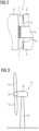
- Fig. 1shows main components of an electrical connection device 1.
- the sliding connectorin this case a brush, is not shown in fig. 1 .
- the electrical connection device 1comprises a holder 2 made of metal, in this case a brush holder. Installed on the holder 2 is a spring 3 for spring-loading the brush, which is not shown in fig. 1 and is to be inserted into a receiving portion 4 of the holder 2.
- the holder 2consists of electrically conducting metal and integrally comprises two spark gap elements 5, one on each side of the receiving portion 4.
- the holder and the spark gap elements 5are one integral piece, since they have been moulded using a shared mould. In other words, the spark gap elements 5 are incorporated into the holder 2 such that neither a mounting plate nor any attachment means are required.
- each spark gap element 5is serrated such that the flux lines around the tips of the spark gap elements 5 are reinforced, facilitating the ignition of an electric arc in the spark gap formed between each spark gap element 5 and the respective electrical connector 6 of a second component of the wind turbine, while the electrical connection device 1 is attached or connected to a first component of the wind turbine.
- Fig. 2shows the spark gaps 7 and also the direct, permanent electrically conductive connection between the electrical connector 6 and the electrical connection device 1 established by the brush 8. This direct, permanent electrically conductive connection is established over a range of relative positions by virtue of the spring 3.
- Figs. 1 and 2also show optional spacers 9 preventing direct contact of the spark gap elements 5 with the electrical connector 6. These spacers 9 may, for example, be placed adjacent to the spark gap elements 5 on a wall section 10 of the holder 2.
- Fig. 3shows an exemplary wind turbine 11 according to the current invention.
- the wind turbine 11comprises a tower 12 carrying a nacelle 13 to which a rotor hub 14 having, in this case, three blades 15 (of which only two are visible) is mounted.
- the wind turbine 11also comprises a lightning protection system employing at least one of the electrical connection devices 1 as explained with respect to figs. 1 and 2 .
- each blade 15comprises a lightning down-conductor 17 electrically connected to the electrical connector 6.
- an electrical connection device 1is mounted to the rotor hub 14 using a conductor 18, such that, in case of a lightning strike, currents due to the lightning pass along the lightning down-conductor 17 through the electrical connector 6, the electrical connection device 1 and the conductor 18 into the rotor hub 14, bypassing the pitching device 16, in particular its bearing elements.
- the electrical connection device 1may also be mounted to the blade 15. Further, additional electrical connection devices 1 as described with respect to figs. 1 and 2 may also be used in the wind turbine 11, for example regarding the tower 12 and the nacelle 13 as pair of first and second components.
Landscapes
- Engineering & Computer Science (AREA)
- Life Sciences & Earth Sciences (AREA)
- Sustainable Development (AREA)
- Sustainable Energy (AREA)
- Chemical & Material Sciences (AREA)
- Combustion & Propulsion (AREA)
- Mechanical Engineering (AREA)
- General Engineering & Computer Science (AREA)
- Wind Motors (AREA)
Description
- The invention concerns an electrical connection device for a lightning protection system in a wind turbine, the electrical connection device being mountable to a first component of the wind turbine and comprising a sliding connection assembly providing an electrical connection between the electrical connection device and a respective electrical connector of a second component of the wind turbine, wherein the first and second components are movable relative to each other, and a spark gap element providing a spark gap between the first and second components, wherein the sliding connection assembly comprises a holder and a sliding connector mounted, in particular spring-loadedly, to the holder. The invention further concerns a method for producing such an electrical connection device and a wind turbine.
- Wind turbines, as tall, erect structures, may be subject to lightning strike. For example, the lightning may use a path from a blade through a rotor hub, a nacelle and a tower to the ground. Components of the wind turbine, for example the blade and the rotor hub or the nacelle and the tower, are movable relative to each other, such that they are connected by, for example, a bearing. During a lightning strike, very high lightning currents have to be conducted by the respective components of the wind turbine, which may cause damage, in particular to the mentioned bearings or other connection devices.
- To protect these elements of a wind turbine, lightning protection systems have been proposed in the state of the art. Those lightning protection systems usually comprise down-conductors in the blades of the wind turbine themselves and electrical connection devices for pairs of components relatively movable against each other, for example, a respective pitchable blade and the rotor hub, and/or the nacelle and the tower. These electrical connection devices serve to provide an alternate path for the lightning current, in this manner protecting the more damageable parts in the connection area, for example bearings.
- Early lightning protection systems used a spark gap element providing a spark gap as a connector in the electrical connection means. During the main discharge of a lightning, where a very strong lightning current flows within a very short period of time, an electric arc is generated in the spark gap due to the strong electrical fields. In the electric arc, due to the low electrical resistance, the lightning current, apart from a small portion, passes through the spark gap and flows to the ground. Such a spark gap, however, provides no protection regarding the lower so-called leaders or leading currents occurring before the actual resistance.
- Regarding this problem, in
EP 1 561 030 B1 , it has been proposed to provide an improved lightning down-conducting arrangement for a wind turbine, in which a sliding contact connection is provided parallel to the spark gap between the lightning down-conductor and the rotor hub, said sliding contact connection ensuring an electrical contact between said lightning down-conductor and said rotor hub irrespective of the pitch angle of the blade, since, in the embodiment described therein, a pitch-controlled wind turbine is discussed. In this manner, a permanent electrical connection can be obtained between the lightning down-conductor of the blade and the rotor hub. Furthermore, upward leaders can be generated from the receptors of the blade or the outer lightning down-conductors with the result that the probability of lightning strike in the receptor or in the outer lightning conductors is optimized. During the actual main discharge, the so-called return stroke, where very strong current flows within a very short period of time, an electric arc is simultaneously generated in the spark gap due to the very strong electrical potential applying after the short-circuiting of the leaders. As a result, the electrical resistance is very weak in the spark gap with the result that the lightning current passes through the spark gap to the ground. As the electrical resistance in the spark gap is much weaker than the contact resistance in the sliding contact connection, only a small non-destructive portion of the lightning current passes through the sliding contact connection. - In an embodiment of
EP 1 561 030 B1 , the collector shoe and the spark gap member are combined in one contact unit, thereby obtaining a particularly simple and compact structure which is easily maintained or replaced. To achieve this, a contact unit includes a mounting plate, a spark gap member and a collector shoe being mounted on said mounting plate. The collector shoe can be made of a carbon brush or may be shaped as a brush or a spring-loaded shoe and be made of, for example, graphite, bronze, brass or carbon fibre. Usually, such a brush or, in general, sliding connection assembly comprises a holder and a sliding connector mounted to the holder. In many cases, the sliding connector, which may be a brush or shoe, is spring-loaded using a spring of the sliding connection assembly. - In summary, in current lightning protection systems for a wind turbine, a first path to guide the electrical current, in particular from a rotating component to a static component, is provided by a sliding connector, in particular a brush, wherein a second path is provided by a spark gap. The spark gap may, in particular, be produced as a separate blade and mounted, together with the sliding connection assembly, to the mounting plate.
- An example of a prior art device is known from
EP 3 080 447 A1 - It is an object of the current invention to provide an improved electrical connection device for a lightning protection system in a wind turbine, which is, in particular, easier to handle and more cost-efficient.
- This object is achieved in an electrical connection device as initially described by providing the spark gap element as a part of the holder.
- In other words, the spark gap element, which may also be named spark gap member, is incorporated in the holder of the sliding connection assembly, such that a mounting plate is no longer needed. In consequence, less parts are required to be mounted to ensure the function of the electrical connection device, in particular the spark gap. According to the state of the art, a spark gap member needed to be mounted to the mounting plate using bolts and washers, which is no longer necessary. Therefore, savings regarding effort and cost are achieved.
- Preferably, the spark gap element is an integral part of the holder. In particular, in especially preferred embodiments, the holder and the at least one spark gap element are one moulded piece. In this manner, there is no need to attach or mount the spark gap element to the holder since both elements/members are produced as a single piece, in particular by moulding. For example, a mould can be used which is enhanced such that a piece is formed which incorporates the spark gap element in addition to the usual structural parts of the holder.
- According to the invention, the holder comprises a receiving portion for the sliding connector at one side, wherein the receiving portion and thus the sliding connector is flanked by two spark gap elements. That is, according to the invention, a spark gap is provided on opposing sides of the sliding connector, such that a symmetrical arrangement is provided, wherein, in the case of a lightning current during the main discharge, electrical arcs may be created on both sides of the sliding connector, such that the portion of the lightning current passing through the sliding connector can be further minimized.
- In embodiments, the holder also comprises at least one spacer, in particular provided on the connection side and/or between the spark gap element and the sliding connector. Such spacers may prevent the spark gap element from coming into direct contact with the respective electrical connector of the second component of the wind turbine. Such spacers, which are in principle known in the state of the art, may in particular be arranged on a wall section of the holder which is positioned in an area between the spark gap element and the sliding connector. In the preferred case of two spark gap elements flanking the sliding connector, also two spacers may be provided on each respective side of the sliding connector.
- Preferably, the sliding connector is a brush, in particular a spring-loaded brush. Alternatively, the sliding connector may also be an electrical shoe or the like.
- The invention further concerns a wind turbine, comprising at least one first and at least one second component and a lightning protection system, the lightning protection system comprising at least one electrical connection device according to the current invention for electrical connection of at least one pair of first and second components. All features and remarks regarding the electrical connection device of the lightning protection system correspondingly apply to the wind turbine according to the invention, such that the same advantages can be achieved.
- In particular, the pairs of components comprise at least one blade and a rotor hub, usually multiple pairs of blades and the rotor hub. For example, a wind turbine may have three blades rotatably mounted on the rotor hub, wherein each of the blades as second components may comprise an electrical connector and the rotor hub may comprise at least one corresponding electrical connection device. However, the electrical connection device according to the invention may also be applied to other pairs of first and second components, for example a nacelle and a tower.
- In a method for producing an electrical connection device according to the current invention, the holder and the at least one spark gap element are moulded as one piece. In this manner, the at least one spark gap element forms an integral part of the holder, such that no attachment means and no attachment step is required and no mounting plate is to be provided.
- Further details and advantages of the current invention become apparent from the following description of preferred embodiments taken in conjunction with the drawings, in which:
- Fig. 1
- is a perspective view of an electrical connection device according to the invention,
- Fig. 2
- shows a cross-sectional view of the electrical connection device in a wind turbine,
- Fig. 3
- shows a wind turbine according to the invention, and
- Fig. 4
- shows a detail of a blade and a rotor hub of the wind turbine.
Fig. 1 shows main components of an electrical connection device 1. To provide for a better understanding, the sliding connector, in this case a brush, is not shown infig. 1 .- The electrical connection device 1 comprises a
holder 2 made of metal, in this case a brush holder. Installed on theholder 2 is aspring 3 for spring-loading the brush, which is not shown infig. 1 and is to be inserted into a receivingportion 4 of theholder 2. Theholder 2 consists of electrically conducting metal and integrally comprises twospark gap elements 5, one on each side of the receivingportion 4. The holder and thespark gap elements 5 are one integral piece, since they have been moulded using a shared mould. In other words, thespark gap elements 5 are incorporated into theholder 2 such that neither a mounting plate nor any attachment means are required. - The surface of each
spark gap element 5 is serrated such that the flux lines around the tips of thespark gap elements 5 are reinforced, facilitating the ignition of an electric arc in the spark gap formed between eachspark gap element 5 and the respectiveelectrical connector 6 of a second component of the wind turbine, while the electrical connection device 1 is attached or connected to a first component of the wind turbine. Fig. 2 shows thespark gaps 7 and also the direct, permanent electrically conductive connection between theelectrical connector 6 and the electrical connection device 1 established by thebrush 8. This direct, permanent electrically conductive connection is established over a range of relative positions by virtue of thespring 3.Figs. 1 and2 also showoptional spacers 9 preventing direct contact of thespark gap elements 5 with theelectrical connector 6. Thesespacers 9 may, for example, be placed adjacent to thespark gap elements 5 on awall section 10 of theholder 2.Fig. 3 shows anexemplary wind turbine 11 according to the current invention. Thewind turbine 11 comprises atower 12 carrying anacelle 13 to which arotor hub 14 having, in this case, three blades 15 (of which only two are visible) is mounted. Thewind turbine 11 also comprises a lightning protection system employing at least one of the electrical connection devices 1 as explained with respect tofigs. 1 and2 . As illustrated regarding the example of therotor hub 14 as a first component and ablade 15 as a second component, wherein, in this case, theblade 15 is pitchable using arespective pitch device 16, eachblade 15 comprises a lightning down-conductor 17 electrically connected to theelectrical connector 6. On the other hand, an electrical connection device 1 according to the invention is mounted to therotor hub 14 using aconductor 18, such that, in case of a lightning strike, currents due to the lightning pass along the lightning down-conductor 17 through theelectrical connector 6, the electrical connection device 1 and theconductor 18 into therotor hub 14, bypassing thepitching device 16, in particular its bearing elements.- It is noted that, in another embodiment, the electrical connection device 1 may also be mounted to the
blade 15. Further, additional electrical connection devices 1 as described with respect tofigs. 1 and2 may also be used in thewind turbine 11, for example regarding thetower 12 and thenacelle 13 as pair of first and second components. - Although the present invention has been described in detail with reference to the preferred embodiment, the present invention is not limited by the disclosed examples from which the skilled person is able to derive other variations without departing from the scope of the invention.
Claims (8)
- Electrical connection device (1) for a lightning protection system in a wind turbine (11), the electrical connection device (1) being mountable to a first component of the wind turbine (11) and comprising a sliding connection assembly providing when mounted to a wind turbine an electrical connection between the electrical connection device (1) and a respective electrical connector (6) of a second component of the wind turbine (11), wherein the first and second components are movable relative to each other, and a spark gap element (5) providing a spark gap (7) between the first and second components, wherein the sliding connection assembly comprises a holder (2) and a sliding connector mounted, in particular spring-loadedly, to the holder (2),wherein the spark gap element (5) is provided as a part of the holder (2); andcharacterised in that the holder (2) comprises a receiving portion (4) for the sliding connector at one side, wherein the receiving portion (4) and thus the sliding connector is flanked by two spark gap elements (5).
- Electrical connection device according to claim 1,characterised in that the spark gap element (5) is an integral part of the holder (2).
- Electrical connection device according to claim 1 or 2,characterised in that the holder (2) and the spark gap element (5) are one moulded piece.
- Electrical connection device according to one of the preceding claims,characterized in that the holder (2) also comprises at least one spacer (9), in particular provided on the connection side and/or between the spark gap element (5) and the sliding connector.
- Electrical connection device according to one of the preceding claims,characterised in that the sliding connector is a brush (8).
- Wind turbine (11), comprising at least one first and at least one second component and a lightning protection system, the lightning protection system comprising at least one electrical connection device (1) according to one of the preceding claims for electrical connection of at least one pair of first and second components.
- Wind turbine according to claim 6,characterised in that the pairs of components comprise at least one blade (15) and a rotor hub (14), and/or a nacelle (13) and a tower (12).
- Method for producing an electrical connection device (1) according to any of the claims 1 to 5, wherein the holder (2) and the at least one spark gap element (5) are moulded as one piece.
Applications Claiming Priority (2)
| Application Number | Priority Date | Filing Date | Title |
|---|---|---|---|
| EP19169874.5AEP3726051A1 (en) | 2019-04-17 | 2019-04-17 | Electrical connection device for a wind turbine, wind turbine and method for producing an electrical connection device |
| PCT/EP2020/057074WO2020212043A1 (en) | 2019-04-17 | 2020-03-16 | Electrical connection device for a wind turbine, wind turbine and method for producing an electrical connection device |
Publications (2)
| Publication Number | Publication Date |
|---|---|
| EP3935280A1 EP3935280A1 (en) | 2022-01-12 |
| EP3935280B1true EP3935280B1 (en) | 2024-04-03 |
Family
ID=66217963
Family Applications (2)
| Application Number | Title | Priority Date | Filing Date |
|---|---|---|---|
| EP19169874.5AWithdrawnEP3726051A1 (en) | 2019-04-17 | 2019-04-17 | Electrical connection device for a wind turbine, wind turbine and method for producing an electrical connection device |
| EP20714914.7AActiveEP3935280B1 (en) | 2019-04-17 | 2020-03-16 | Electrical connection device for a wind turbine, wind turbine and method for producing an electrical connection device |
Family Applications Before (1)
| Application Number | Title | Priority Date | Filing Date |
|---|---|---|---|
| EP19169874.5AWithdrawnEP3726051A1 (en) | 2019-04-17 | 2019-04-17 | Electrical connection device for a wind turbine, wind turbine and method for producing an electrical connection device |
Country Status (3)
| Country | Link |
|---|---|
| EP (2) | EP3726051A1 (en) |
| DK (1) | DK3935280T3 (en) |
| WO (1) | WO2020212043A1 (en) |
Families Citing this family (1)
| Publication number | Priority date | Publication date | Assignee | Title |
|---|---|---|---|---|
| CN113757054B (en)* | 2021-10-27 | 2023-03-28 | 上海电气风电集团股份有限公司 | Down-lead sliding connection device of wind generating set |
Citations (2)
| Publication number | Priority date | Publication date | Assignee | Title |
|---|---|---|---|---|
| EP1561030B1 (en)* | 2002-11-12 | 2006-08-02 | Lm Glasfiber A/S | Lightning protection of a pitch-controlled wind turbine blade |
| EP3080447B1 (en)* | 2013-12-09 | 2019-06-12 | Vestas Wind Systems A/S | Rotor-blade discharge unit for wind turbines |
Family Cites Families (1)
| Publication number | Priority date | Publication date | Assignee | Title |
|---|---|---|---|---|
| EP2336560A1 (en)* | 2009-12-15 | 2011-06-22 | Vestas Wind Systems A/S | Lightning current transfer assembly for a wind turbine |
- 2019
- 2019-04-17EPEP19169874.5Apatent/EP3726051A1/ennot_activeWithdrawn
- 2020
- 2020-03-16DKDK20714914.7Tpatent/DK3935280T3/enactive
- 2020-03-16EPEP20714914.7Apatent/EP3935280B1/enactiveActive
- 2020-03-16WOPCT/EP2020/057074patent/WO2020212043A1/ennot_activeCeased
Patent Citations (2)
| Publication number | Priority date | Publication date | Assignee | Title |
|---|---|---|---|---|
| EP1561030B1 (en)* | 2002-11-12 | 2006-08-02 | Lm Glasfiber A/S | Lightning protection of a pitch-controlled wind turbine blade |
| EP3080447B1 (en)* | 2013-12-09 | 2019-06-12 | Vestas Wind Systems A/S | Rotor-blade discharge unit for wind turbines |
Also Published As
| Publication number | Publication date |
|---|---|
| EP3935280A1 (en) | 2022-01-12 |
| WO2020212043A1 (en) | 2020-10-22 |
| DK3935280T3 (en) | 2024-05-21 |
| EP3726051A1 (en) | 2020-10-21 |
Similar Documents
| Publication | Publication Date | Title |
|---|---|---|
| US11225949B2 (en) | Lightning protection systems for wind turbine blades | |
| US7377750B1 (en) | Lightning protection system for a wind turbine | |
| EP2510229B1 (en) | Wind turbine with a lightning protection system | |
| US7390169B2 (en) | Lightning protection of a pitch-controlled wind turbine blade | |
| EP2789067B1 (en) | Lightning current transfer system for a wind turbine generator | |
| EP1514024B1 (en) | Lightning protection means for a wind turbine | |
| US10215163B2 (en) | Lightning current transfer system with spark gap and wind turbine using the lightning current transfer system | |
| CN111911345B (en) | Blade for a wind turbine and wind turbine | |
| GB2519332A (en) | Improvements relating to lightning protection systems for wind turbine blades | |
| CA2852598A1 (en) | Wind turbine rotor blade having an electrical heating device and a plurality of lightning conductors | |
| EP3093487B1 (en) | Lightning protection system for wind turbine rotor blades | |
| EP3744972B1 (en) | Rotor for a wind turbine and wind turbine | |
| EP3935280B1 (en) | Electrical connection device for a wind turbine, wind turbine and method for producing an electrical connection device | |
| CN105386943A (en) | Wind driven generator blade point lightning protection device | |
| WO2021180389A1 (en) | Wind turbine blade assembly and method for manufacturing | |
| EP3786451A1 (en) | Wind turbine | |
| EP3775544B1 (en) | Electrical protection system for wind turbines | |
| EP3628864B1 (en) | Wind turbine | |
| CN111033033B (en) | Wind turbine rotor blade and lightning protection system for a wind turbine rotor blade | |
| EP4293222A1 (en) | Rotor blade with lightning protection system, wind turbine and assembly method | |
| EP4556711A1 (en) | Wind turbine rotor blade improved for lightning protection |
Legal Events
| Date | Code | Title | Description |
|---|---|---|---|
| STAA | Information on the status of an ep patent application or granted ep patent | Free format text:STATUS: UNKNOWN | |
| STAA | Information on the status of an ep patent application or granted ep patent | Free format text:STATUS: THE INTERNATIONAL PUBLICATION HAS BEEN MADE | |
| PUAI | Public reference made under article 153(3) epc to a published international application that has entered the european phase | Free format text:ORIGINAL CODE: 0009012 | |
| STAA | Information on the status of an ep patent application or granted ep patent | Free format text:STATUS: REQUEST FOR EXAMINATION WAS MADE | |
| 17P | Request for examination filed | Effective date:20211008 | |
| AK | Designated contracting states | Kind code of ref document:A1 Designated state(s):AL AT BE BG CH CY CZ DE DK EE ES FI FR GB GR HR HU IE IS IT LI LT LU LV MC MK MT NL NO PL PT RO RS SE SI SK SM TR | |
| DAV | Request for validation of the european patent (deleted) | ||
| DAX | Request for extension of the european patent (deleted) | ||
| GRAP | Despatch of communication of intention to grant a patent | Free format text:ORIGINAL CODE: EPIDOSNIGR1 | |
| STAA | Information on the status of an ep patent application or granted ep patent | Free format text:STATUS: GRANT OF PATENT IS INTENDED | |
| INTG | Intention to grant announced | Effective date:20231106 | |
| GRAS | Grant fee paid | Free format text:ORIGINAL CODE: EPIDOSNIGR3 | |
| GRAA | (expected) grant | Free format text:ORIGINAL CODE: 0009210 | |
| STAA | Information on the status of an ep patent application or granted ep patent | Free format text:STATUS: THE PATENT HAS BEEN GRANTED | |
| AK | Designated contracting states | Kind code of ref document:B1 Designated state(s):AL AT BE BG CH CY CZ DE DK EE ES FI FR GB GR HR HU IE IS IT LI LT LU LV MC MK MT NL NO PL PT RO RS SE SI SK SM TR | |
| REG | Reference to a national code | Ref country code:CH Ref legal event code:EP | |
| REG | Reference to a national code | Ref country code:IE Ref legal event code:FG4D | |
| REG | Reference to a national code | Ref country code:DE Ref legal event code:R096 Ref document number:602020028310 Country of ref document:DE | |
| REG | Reference to a national code | Ref country code:DK Ref legal event code:T3 Effective date:20240517 | |
| REG | Reference to a national code | Ref country code:LT Ref legal event code:MG9D | |
| REG | Reference to a national code | Ref country code:NL Ref legal event code:MP Effective date:20240403 | |
| REG | Reference to a national code | Ref country code:AT Ref legal event code:MK05 Ref document number:1672580 Country of ref document:AT Kind code of ref document:T Effective date:20240403 | |
| PG25 | Lapsed in a contracting state [announced via postgrant information from national office to epo] | Ref country code:NL Free format text:LAPSE BECAUSE OF FAILURE TO SUBMIT A TRANSLATION OF THE DESCRIPTION OR TO PAY THE FEE WITHIN THE PRESCRIBED TIME-LIMIT Effective date:20240403 | |
| PG25 | Lapsed in a contracting state [announced via postgrant information from national office to epo] | Ref country code:NL Free format text:LAPSE BECAUSE OF FAILURE TO SUBMIT A TRANSLATION OF THE DESCRIPTION OR TO PAY THE FEE WITHIN THE PRESCRIBED TIME-LIMIT Effective date:20240403 | |
| PG25 | Lapsed in a contracting state [announced via postgrant information from national office to epo] | Ref country code:IS Free format text:LAPSE BECAUSE OF FAILURE TO SUBMIT A TRANSLATION OF THE DESCRIPTION OR TO PAY THE FEE WITHIN THE PRESCRIBED TIME-LIMIT Effective date:20240803 | |
| PG25 | Lapsed in a contracting state [announced via postgrant information from national office to epo] | Ref country code:BG Free format text:LAPSE BECAUSE OF FAILURE TO SUBMIT A TRANSLATION OF THE DESCRIPTION OR TO PAY THE FEE WITHIN THE PRESCRIBED TIME-LIMIT Effective date:20240403 | |
| PG25 | Lapsed in a contracting state [announced via postgrant information from national office to epo] | Ref country code:HR Free format text:LAPSE BECAUSE OF FAILURE TO SUBMIT A TRANSLATION OF THE DESCRIPTION OR TO PAY THE FEE WITHIN THE PRESCRIBED TIME-LIMIT Effective date:20240403 Ref country code:FI Free format text:LAPSE BECAUSE OF FAILURE TO SUBMIT A TRANSLATION OF THE DESCRIPTION OR TO PAY THE FEE WITHIN THE PRESCRIBED TIME-LIMIT Effective date:20240403 | |
| PG25 | Lapsed in a contracting state [announced via postgrant information from national office to epo] | Ref country code:GR Free format text:LAPSE BECAUSE OF FAILURE TO SUBMIT A TRANSLATION OF THE DESCRIPTION OR TO PAY THE FEE WITHIN THE PRESCRIBED TIME-LIMIT Effective date:20240704 | |
| PG25 | Lapsed in a contracting state [announced via postgrant information from national office to epo] | Ref country code:PT Free format text:LAPSE BECAUSE OF FAILURE TO SUBMIT A TRANSLATION OF THE DESCRIPTION OR TO PAY THE FEE WITHIN THE PRESCRIBED TIME-LIMIT Effective date:20240805 | |
| PG25 | Lapsed in a contracting state [announced via postgrant information from national office to epo] | Ref country code:ES Free format text:LAPSE BECAUSE OF FAILURE TO SUBMIT A TRANSLATION OF THE DESCRIPTION OR TO PAY THE FEE WITHIN THE PRESCRIBED TIME-LIMIT Effective date:20240403 | |
| PG25 | Lapsed in a contracting state [announced via postgrant information from national office to epo] | Ref country code:CZ Free format text:LAPSE BECAUSE OF FAILURE TO SUBMIT A TRANSLATION OF THE DESCRIPTION OR TO PAY THE FEE WITHIN THE PRESCRIBED TIME-LIMIT Effective date:20240403 | |
| PG25 | Lapsed in a contracting state [announced via postgrant information from national office to epo] | Ref country code:AT Free format text:LAPSE BECAUSE OF FAILURE TO SUBMIT A TRANSLATION OF THE DESCRIPTION OR TO PAY THE FEE WITHIN THE PRESCRIBED TIME-LIMIT Effective date:20240403 | |
| PG25 | Lapsed in a contracting state [announced via postgrant information from national office to epo] | Ref country code:PL Free format text:LAPSE BECAUSE OF FAILURE TO SUBMIT A TRANSLATION OF THE DESCRIPTION OR TO PAY THE FEE WITHIN THE PRESCRIBED TIME-LIMIT Effective date:20240403 | |
| PG25 | Lapsed in a contracting state [announced via postgrant information from national office to epo] | Ref country code:LV Free format text:LAPSE BECAUSE OF FAILURE TO SUBMIT A TRANSLATION OF THE DESCRIPTION OR TO PAY THE FEE WITHIN THE PRESCRIBED TIME-LIMIT Effective date:20240403 | |
| PG25 | Lapsed in a contracting state [announced via postgrant information from national office to epo] | Ref country code:PT Free format text:LAPSE BECAUSE OF FAILURE TO SUBMIT A TRANSLATION OF THE DESCRIPTION OR TO PAY THE FEE WITHIN THE PRESCRIBED TIME-LIMIT Effective date:20240805 Ref country code:PL Free format text:LAPSE BECAUSE OF FAILURE TO SUBMIT A TRANSLATION OF THE DESCRIPTION OR TO PAY THE FEE WITHIN THE PRESCRIBED TIME-LIMIT Effective date:20240403 Ref country code:NO Free format text:LAPSE BECAUSE OF FAILURE TO SUBMIT A TRANSLATION OF THE DESCRIPTION OR TO PAY THE FEE WITHIN THE PRESCRIBED TIME-LIMIT Effective date:20240703 Ref country code:LV Free format text:LAPSE BECAUSE OF FAILURE TO SUBMIT A TRANSLATION OF THE DESCRIPTION OR TO PAY THE FEE WITHIN THE PRESCRIBED TIME-LIMIT Effective date:20240403 Ref country code:IS Free format text:LAPSE BECAUSE OF FAILURE TO SUBMIT A TRANSLATION OF THE DESCRIPTION OR TO PAY THE FEE WITHIN THE PRESCRIBED TIME-LIMIT Effective date:20240803 Ref country code:HR Free format text:LAPSE BECAUSE OF FAILURE TO SUBMIT A TRANSLATION OF THE DESCRIPTION OR TO PAY THE FEE WITHIN THE PRESCRIBED TIME-LIMIT Effective date:20240403 Ref country code:GR Free format text:LAPSE BECAUSE OF FAILURE TO SUBMIT A TRANSLATION OF THE DESCRIPTION OR TO PAY THE FEE WITHIN THE PRESCRIBED TIME-LIMIT Effective date:20240704 Ref country code:FI Free format text:LAPSE BECAUSE OF FAILURE TO SUBMIT A TRANSLATION OF THE DESCRIPTION OR TO PAY THE FEE WITHIN THE PRESCRIBED TIME-LIMIT Effective date:20240403 Ref country code:ES Free format text:LAPSE BECAUSE OF FAILURE TO SUBMIT A TRANSLATION OF THE DESCRIPTION OR TO PAY THE FEE WITHIN THE PRESCRIBED TIME-LIMIT Effective date:20240403 Ref country code:CZ Free format text:LAPSE BECAUSE OF FAILURE TO SUBMIT A TRANSLATION OF THE DESCRIPTION OR TO PAY THE FEE WITHIN THE PRESCRIBED TIME-LIMIT Effective date:20240403 Ref country code:BG Free format text:LAPSE BECAUSE OF FAILURE TO SUBMIT A TRANSLATION OF THE DESCRIPTION OR TO PAY THE FEE WITHIN THE PRESCRIBED TIME-LIMIT Effective date:20240403 Ref country code:AT Free format text:LAPSE BECAUSE OF FAILURE TO SUBMIT A TRANSLATION OF THE DESCRIPTION OR TO PAY THE FEE WITHIN THE PRESCRIBED TIME-LIMIT Effective date:20240403 Ref country code:RS Free format text:LAPSE BECAUSE OF FAILURE TO SUBMIT A TRANSLATION OF THE DESCRIPTION OR TO PAY THE FEE WITHIN THE PRESCRIBED TIME-LIMIT Effective date:20240703 | |
| REG | Reference to a national code | Ref country code:DE Ref legal event code:R097 Ref document number:602020028310 Country of ref document:DE | |
| PG25 | Lapsed in a contracting state [announced via postgrant information from national office to epo] | Ref country code:EE Free format text:LAPSE BECAUSE OF FAILURE TO SUBMIT A TRANSLATION OF THE DESCRIPTION OR TO PAY THE FEE WITHIN THE PRESCRIBED TIME-LIMIT Effective date:20240403 | |
| PG25 | Lapsed in a contracting state [announced via postgrant information from national office to epo] | Ref country code:SK Free format text:LAPSE BECAUSE OF FAILURE TO SUBMIT A TRANSLATION OF THE DESCRIPTION OR TO PAY THE FEE WITHIN THE PRESCRIBED TIME-LIMIT Effective date:20240403 Ref country code:RO Free format text:LAPSE BECAUSE OF FAILURE TO SUBMIT A TRANSLATION OF THE DESCRIPTION OR TO PAY THE FEE WITHIN THE PRESCRIBED TIME-LIMIT Effective date:20240403 | |
| PG25 | Lapsed in a contracting state [announced via postgrant information from national office to epo] | Ref country code:SM Free format text:LAPSE BECAUSE OF FAILURE TO SUBMIT A TRANSLATION OF THE DESCRIPTION OR TO PAY THE FEE WITHIN THE PRESCRIBED TIME-LIMIT Effective date:20240403 | |
| PG25 | Lapsed in a contracting state [announced via postgrant information from national office to epo] | Ref country code:SM Free format text:LAPSE BECAUSE OF FAILURE TO SUBMIT A TRANSLATION OF THE DESCRIPTION OR TO PAY THE FEE WITHIN THE PRESCRIBED TIME-LIMIT Effective date:20240403 Ref country code:SK Free format text:LAPSE BECAUSE OF FAILURE TO SUBMIT A TRANSLATION OF THE DESCRIPTION OR TO PAY THE FEE WITHIN THE PRESCRIBED TIME-LIMIT Effective date:20240403 Ref country code:RO Free format text:LAPSE BECAUSE OF FAILURE TO SUBMIT A TRANSLATION OF THE DESCRIPTION OR TO PAY THE FEE WITHIN THE PRESCRIBED TIME-LIMIT Effective date:20240403 Ref country code:EE Free format text:LAPSE BECAUSE OF FAILURE TO SUBMIT A TRANSLATION OF THE DESCRIPTION OR TO PAY THE FEE WITHIN THE PRESCRIBED TIME-LIMIT Effective date:20240403 | |
| PLBE | No opposition filed within time limit | Free format text:ORIGINAL CODE: 0009261 | |
| STAA | Information on the status of an ep patent application or granted ep patent | Free format text:STATUS: NO OPPOSITION FILED WITHIN TIME LIMIT | |
| 26N | No opposition filed | Effective date:20250106 | |
| PGFP | Annual fee paid to national office [announced via postgrant information from national office to epo] | Ref country code:DE Payment date:20250327 Year of fee payment:6 | |
| PGFP | Annual fee paid to national office [announced via postgrant information from national office to epo] | Ref country code:DK Payment date:20250325 Year of fee payment:6 | |
| PG25 | Lapsed in a contracting state [announced via postgrant information from national office to epo] | Ref country code:SI Free format text:LAPSE BECAUSE OF FAILURE TO SUBMIT A TRANSLATION OF THE DESCRIPTION OR TO PAY THE FEE WITHIN THE PRESCRIBED TIME-LIMIT Effective date:20240403 | |
| PGFP | Annual fee paid to national office [announced via postgrant information from national office to epo] | Ref country code:FR Payment date:20250324 Year of fee payment:6 | |
| PGFP | Annual fee paid to national office [announced via postgrant information from national office to epo] | Ref country code:GB Payment date:20250325 Year of fee payment:6 | |
| PG25 | Lapsed in a contracting state [announced via postgrant information from national office to epo] | Ref country code:SE Free format text:LAPSE BECAUSE OF FAILURE TO SUBMIT A TRANSLATION OF THE DESCRIPTION OR TO PAY THE FEE WITHIN THE PRESCRIBED TIME-LIMIT Effective date:20240403 |