EP3927215B1 - Body support member - Google Patents
Body support memberDownload PDFInfo
- Publication number
- EP3927215B1 EP3927215B1EP20759280.9AEP20759280AEP3927215B1EP 3927215 B1EP3927215 B1EP 3927215B1EP 20759280 AEP20759280 AEP 20759280AEP 3927215 B1EP3927215 B1EP 3927215B1
- Authority
- EP
- European Patent Office
- Prior art keywords
- support
- textile material
- edge
- peripheral edge
- carrier frame
- Prior art date
- Legal status (The legal status is an assumption and is not a legal conclusion. Google has not performed a legal analysis and makes no representation as to the accuracy of the status listed.)
- Active
Links
Images


Classifications
- A—HUMAN NECESSITIES
- A47—FURNITURE; DOMESTIC ARTICLES OR APPLIANCES; COFFEE MILLS; SPICE MILLS; SUCTION CLEANERS IN GENERAL
- A47C—CHAIRS; SOFAS; BEDS
- A47C7/00—Parts, details, or accessories of chairs or stools
- A47C7/02—Seat parts
- A47C7/28—Seat parts with tensioned springs, e.g. of flat type
- A47C7/282—Seat parts with tensioned springs, e.g. of flat type with mesh-like supports, e.g. elastomeric membranes
- A—HUMAN NECESSITIES
- A47—FURNITURE; DOMESTIC ARTICLES OR APPLIANCES; COFFEE MILLS; SPICE MILLS; SUCTION CLEANERS IN GENERAL
- A47C—CHAIRS; SOFAS; BEDS
- A47C31/00—Details or accessories for chairs, beds, or the like, not provided for in other groups of this subclass, e.g. upholstery fasteners, mattress protectors, stretching devices for mattress nets
- A47C31/02—Upholstery attaching means
- A47C31/023—Upholstery attaching means connecting upholstery to frames, e.g. by hooks, clips, snap fasteners, clamping means or the like
- A—HUMAN NECESSITIES
- A47—FURNITURE; DOMESTIC ARTICLES OR APPLIANCES; COFFEE MILLS; SPICE MILLS; SUCTION CLEANERS IN GENERAL
- A47C—CHAIRS; SOFAS; BEDS
- A47C7/00—Parts, details, or accessories of chairs or stools
- A47C7/02—Seat parts
- A47C7/025—Springs not otherwise provided for in A47C7/22 - A47C7/35
- A—HUMAN NECESSITIES
- A47—FURNITURE; DOMESTIC ARTICLES OR APPLIANCES; COFFEE MILLS; SPICE MILLS; SUCTION CLEANERS IN GENERAL
- A47C—CHAIRS; SOFAS; BEDS
- A47C7/00—Parts, details, or accessories of chairs or stools
- A47C7/02—Seat parts
- A47C7/029—Seat parts of non-adjustable shape adapted to a user contour or ergonomic seating positions
- A—HUMAN NECESSITIES
- A47—FURNITURE; DOMESTIC ARTICLES OR APPLIANCES; COFFEE MILLS; SPICE MILLS; SUCTION CLEANERS IN GENERAL
- A47C—CHAIRS; SOFAS; BEDS
- A47C7/00—Parts, details, or accessories of chairs or stools
- A47C7/36—Supports for the head or the back
- A47C7/40—Supports for the head or the back for the back
Definitions
- the present applicationrelates generally to a body support assembly, for example a chair, and in particular to a body support member.
- Chairsmay have a body support member configured with a suspension material, such as a mesh fabric, that is stretched across a frame.
- suspension materialsconform to the body of the user, providing micro compliance along with improved air circulation, and the attendant cooling benefit.
- the framemust be rigid in order to maintain an appropriate level of tension in the suspension material.
- Such rigiditymay limit, however, the flexibility of the body support member, and introduce unforgiving pressure points around the perimeter of the frame.
- suspension materials installed on a seat of a chairare typically required to sustain higher tensions due to the load being applied thereto by a seated user, which may exacerbate the limited flexibility and rigidity of the supporting structure.
- such tilt mechanismstypically include one or more rigid links, and mechanical connections, which are rigid and non-compliant, which result in a more rigid and less forgiving ride, and which may lead to a less desirable user experience.
- systems relying on the materiality of the seating structure to introduce the appropriate kinematics and flexibilitymay not be suitable to support a suspension material.
- body support surfacesmay be defined by one or more foam cushions, foam materials may limit air circulation and often do not provide localized support.
- body support members configured with plastic shells, supported for example by peripheral framestypically do not provide a comfortable body-conforming support surface.
- a body support memberis known for example from US 6 910 741 B2 .
- the present inventionprovides a body support member as defined in claim 1.
- the term “plurality,” as used herein,means two or more.
- the term “longitudinal,” as used hereinmeans of or relating to a length or lengthwise direction 2, 2', for example a direction running from the bottom of a backrest assembly 6 to the top thereof, or vice versa, or from the front of a seat assembly 8 to the rear thereof, or vice versa.
- the term “lateral,” as used herein,means situated on, directed toward or running in a side-to-side direction 4 of a body support assembly 10, shown in one embodiment as an office chair including the backrest assembly 6 and seat assembly 8.
- the body support assemblymay be configured as any structure that supports a body, including without limitation automotive, aircraft and mass-transit seating, beds, home furnishings (including sofas and chairs), and other similar and suitable structures.
- a lateral direction 4corresponds to a horizontal direction and a longitudinal direction 2 corresponds to a vertical direction
- the longitudinal direction 2'corresponds to a horizontal direction.
- the lateral direction 4may be referred to as an X direction
- the longitudinal direction 2, 2'refers to a Y direction
- a Z directionis orthogonal to the body support surface of both the backrest and seat assemblies 6, 8.
- Coupledmeans connected to or engaged with, whether directly or indirectly, for example with an intervening member, and does not require the engagement to be fixed or permanent, although it may be fixed or permanent.
- first, second, and so on, as used hereinare not meant to be assigned to a particular component so designated, but rather are simply referring to such components in the numerical order as addressed, meaning that a component designated as “first” may later be a “second” such component, depending on the order in which it is referred. It should also be understood that designation of "first” and “second” does not necessarily mean that the two components or values so designated are different, meaning for example a first direction may be the same as a second direction, with each simply being applicable to different components.
- the terms “upper,” “lower,” “rear,” “front,” “fore,” “aft,” “vertical,” “horizontal,” “right,” “left,” and variations or derivatives thereof,refer to the orientations of an exemplary body support assembly 10, shown as a chair in FIGS. 1-6 , from the perspective of a user seated therein.
- the term “transverse”means non-parallel.
- the term “outwardly”refers to a direction facing away from a centralized location, for example the phrase “radially outwardly” refers to a feature diverging away from a centralized location, for example the middle or interior region of a seat or backrest, and lies generally in the X Y plane defined by the lateral and longitudinal directions 2, 2', 4.
- textile materialrefers to a flexible material made of a network of natural or artificial fibers (yarn, monofilaments, thread, etc.). Textile materials may be formed by weaving, knitting, crocheting, knotting, felting, or braiding. Textile materials may include various furniture upholstery materials, which may be used for example to cover a foam cushion, and/or suspension materials, which may be stretched or put in tension across an opening to support a user.
- the body support assembly 10is shown as including a tilt control assembly 18, also referred to as a lower support structure, a base structure 12 and the backrest and seat assemblies 6, 8.
- the base structure 12includes a leg assembly 14 and a support column 16 coupled to and extending upwardly from the leg assembly.
- the tilt control assembly 18is supported by and coupled to a top of the support column 16.
- the leg assemblymay alternatively be configured as a fixed structure, for example a four legged base, a sled base or other configuration.
- the support column 16may be height adjustable, including for example and without limitation a telescopic column with a pneumatic, hydraulic or electro-mechanical actuator.
- the leg assembly 14includes a plurality of support legs 22 extending radially outwardly from a hub 24 surrounding the support column. Ends of each support leg may be outfitted with a caster, glide or other floor interface member 20.
- a pair of armrest assemblies 26are coupled to the tilt control assembly 18.
- Various user interface controls 28are provided to actuate and/or adjust the height of the seat, including for example an actuation lever pivotally coupled to the armrest assembly, or to control the tension and/or return force of the tilt control assembly 18.
- the backrest and seat assemblies 6, 8are operably coupled to the tilt control assembly 18, or lower support structure, which controls the movement thereof, for example during recline.
- the tilt control assemblymay include a plurality of rigid control links, which may be mechanically connected, for example via pivot pins, to form a linkage assembly, including for example a four-bar linkage.
- the tilt control assemblyinclude integrally formed links 23, 25, 33, configured for example with strategic deformable locations that allow for predetermined deformations and define "flex regions,” otherwise referred to as "flex joints,” or virtual pivot locations.
- the various configurations of the links and flex regionsmay be configured as shown and disclosed in U.S. Pub. No. 2016/0296026 A1 , entitled “Seating Arrangement,” and in U.S. Pub. No. 2018/0352961 , entitled “Seating Arrangement and Method of Construction".
- the tilt control assembly 18may be configured as a four-bar mechanism as shown in FIG. 21 , with a bottom, or base link 33 connected to the base structure 12 at a first location, and front and rear links 23, 25 connected between the base link and the seat assembly 8.
- the base, front and rear links 33, 23, 25define the lower support structure.
- the front and rear links 23, 25may be pivotally or bendably connected to the base link 33 at flex regions 29, 31, whether integrally formed or otherwise.
- the front and rear links 23, 25may also be pivotally, or bendably connected to the seat assembly 8 at flex regions 27, 53, with the portion 57 of the seat assembly extending between the flex regions 27, 53 defining a link of the four-bar mechanism.
- the flex region 53is formed in the support platform 30 portion of the seat assembly.
- the various flex regions 27, 29, 31, 53may be formed as living hinges, or thin flexible hinges made from the same material as the two more rigid pieces the living hinge connects, so as provide for relative rotation or pivoting between the more rigid pieces by bending of the living hinge.
- the links and bars of the mechanismmay also be configured as rigid links and bars connected at fixed hinge points.
- a usercan move or recline the backrest and seat assemblies 6, 8 from an upright position to a reclined position by flexing the four bar mechanism, including portions of the seat assembly.
- the four-bar linkage arrangement as used and described hereinis inclusive of linkage arrangements comprising additional linkage members, such as five-bar linkage arrangements, six-bar linkage arrangements, and the like.
- the thickness of one or more links 23, 25, 33, 57, and especially the front, base and seat links 23, 33, 57, and predetermined flex regions thereof,may be located to achieve a desired performance characteristic, including for example, the flexibility of the link.
- the thickness of a linkmay vary along the length of the link to achieve a desired flexibility or rigidity across the link or in a localized portion of the link, for example at flex regions 27, 28, 31 and 53.
- the front links and seat assembly linkmay be more flexible than the rear link 25 to achieve the desired flexibility of the four-bar linkage.
- the various linksmay be more flexible in a particular portion or localized area of the link such that the links are generally flexible in the localized area and are generally not flexible or less flexible in any other area of the link. It is noted that the relative areas of reduced thickness may extend along a short distance or the majority of the length of the associated link depending upon the support and bending characteristics desired.
- the seat assembly 8is operably coupled to the tilt control assembly 18 and supports a seating surface 28.
- the seathas opposite sides spaced apart in a lateral direction and a front and rear spaced apart in a first longitudinal direction.
- the seat assemblyincludes a lower support platform 30 having a peripheral edge 32, an upper surface 34 and a lower surface 36.
- the lower support platformhas a generally isosceles trapezoidal shape in plan view (see FIG. 13 ) with a front edge 38, rear edge 40 and side edges 42 joining the front and rear edges.
- the rear edgeis shorter than the front edge.
- the peripheral edge 32may be stepped, meaning a peripheral edge portion 66 thereof is thinner than a central portion 68 thereof.
- the support platform 30has a pair of laterally spaced pads 44 positioned at a forward portion of the support platform. As shown in FIGS. 28A-D , the platform 30 includes a raised portion 970 defining a recess 974 and an opening 972.
- the padsare each defined as a hinge portion 976 with a front edge 978 secured to a front edge 980 of the platform defining the opening 972 in the platform.
- the hinge portionmay be formed by overmolding a more flexible material to the support platform.
- the hinge portion 976extends rearwardly in the opening with a rear edge 982 spaced apart from a rear edge 984 of the platform defining the opening 972.
- Each of the pads 44includes at least one mounting component, shown as openings 46 shaped and dimensioned to receive mounting members (e.g. fasteners or studs 988) for securing the platform to the tilt control assembly, which may include a flange 990 extending forwardly from the link 23 to support the platforms.
- the flange 990is received in the recess 972 and includes bosses extending upwardly into the openings 46 such that the flange 990 may be secured to a bottom surface of the pad, and hinge portion 976 in particular, with the plurality of fasteners 988.
- the flexible hinge portion 976defines the flex region 27.
- the mounting component, and connection to the link 23,allows for pivoting of the support platform and the front link 23 relative to the base link 33 about a flex region 29, and for pivoting of the seat assembly 8 relative to the front link 23 about flex region 27, executed in both cases for example by elastic deformation or bending of portions of the front links at the flex regions 27, 29, or alternatively by bending or flexing of the pads or hinge portion 976.
- the spacing between the pads, and front linksprovides relative stability to the front portion of the seat, which resists rotation or torsional movement about a longitudinal axis.
- a boss structure 49extends downwardly from a rear portion of the support platform.
- the boss structure 49defines at least one mounting component that is connected to the tilt control assembly 18, and/or defines a portion of a rear link 25 forming in part the tilt control assembly and allows for pivoting of the support platform and the rear link 25 relative to the base link 33 about a flex region 31, which may be executed for example by elastic deformation or bending of portions of the base link 33 at flex region 31.
- the boss structure 49has a tubular configuration defining a cavity that surrounds or receives an insert portion of the rear link 25, configured with features from the connector 479, the 219.
- the centrally located rear linkwhich is the only support for the rear of the seat, allows for rotation or torsional movement of the rear of the seat relative to the front of the seat about a longitudinal axis, with the rotation or torsional movement of the front being restricted as previously explained.
- the support platform 30has a generally concave upper surface 34, with front and rear portions 35, 37 extending upwardly from the boss structure.
- the support platformmay be made of a flexibly resilient polymer material such as any thermoplastic, including, for example, nylon, glass-filled nylon, polypropylene, acetyl, or polycarbonate; any thermal set material, including, for example, epoxies; or any resin-based composites, including, for example, carbon fiber or fiberglass, thereby allowing the support platform to conforms and move in response to forces exerted by a user.
- a suitable materialsmay be also be utilized, such as metals, including, for example, steel or titanium; plwood; or composite material including plastics, resin-based composites, metals and/or plywood.
- the support platformmay have strategically positioned tensile substrates, made for example of glass reinforced tape, to accommodate bending and deformation of the structure. Strategic locations on the lower support platform also are provided with specific geometries that allow for predetermined deformations and define "flex regions,” otherwise referred to as "flex joints,” or virtual pivot locations.
- the support platformmay include an area of reduced thickness defining a laterally extending flex region or flexing zone 53 located in front of the boss structure 49, which divides or bifurcates the support platform into front and rear portions, which may have different lengths or dimensions, with the rear portion being downwardly deflectable relative to the front portion during recline as the flex region bends.
- the portion of the support platform extending between the flex region 53 and the flex region 27defines a link of a four-bar mechanism, while a portion of the support platform rearward of the flex region 53 defines in part a portion of the rear link 25.
- the relative areas of reduced thicknessmay extend along a short distance or the majority of the width of the support platform depending upon the support and bending characteristics desired.
- flex regionrefers to a portion of the structure that allows for flexing or bending in the designated region, thereby allowing or providing for relative movement (e.g., pivoting) of the component or structure on opposite sides of the flex region, thereby defining a virtual pivot location, for example a horizontal pivot axis, with the understanding that the virtual pivot axis may move during the flexing, rather than being defined as a hard fixed axis.
- the various configurations and materials of the support platformmay correspond to the configuration and materials of various components as shown and disclosed in U.S. Pub. No. 2016/0296026 A1 , entitled “Seating Arrangement," and in U.S. Pub. No. 2018/0352961 , entitled “Seating Arrangement and Method of Construction".
- a support ring 48has an inner ring 50 with an interior peripheral edge 52 that defines a central opening 54.
- the interior peripheral edge 52surrounds and is coupled to the outer peripheral edge 32 of the support platform, namely the rear edge 40, front edge 38 and side edges 42, of the support platform 30, which is received in the opening 54.
- the inner ring 50has a trapezoidal shape defined by a front member 56, a rear member 58 and a pair of side members 60 defining the opening 54.
- the interior peripheral edge 52may be stepped, meaning a peripheral edge portion 70 thereof is thinner than a central portion 72 thereof, with the edge portion 70 overlapping and mating with the edge portion 66 of the lower support platform. As shown in FIG.
- the edge portion 70is positioned above the edge portion 66, with an upper surface of the peripheral edge 52 lying flush with the upper surface of the support platform 30.
- the edge portions 70, 66may be secured with fasteners, such as screws and/or adhesive. It should be understood that the support platform 30 and support ring 48 in combination define a support frame 62.
- the support ring 48further includes an outer ring 74 with side members 76 joined to side members 60 of the inner ring with a pair of front connectors 78 and a pair of intermediate connectors 80.
- a pair of rear three-sided openings 81are defined between an inner edge of the outer ring 74, an edge of the side member and the edges of the connectors 80.
- the openings 81each have an inner side 85, a longer, outer curved side 87, with the sides 87 and 85 converging along the rear of the opening 81 to define a nose 89, and a third side 91 extending along and defining the connector 80 and joining the sides 85, 87.
- a pair of front three-sided openings 83are defined between an inner edge of the outer ring 74, an edge of the side member 60 and the edges of the connectors 80.
- the openings 83each have an inner side 93, a longer, outer curved side 95, with the sides 93. 95 converging along the front of the opening 83 to define a nose 99, and a third side 97 extending along and defining the connector 80 and joining the sides 93, 95.
- the intermediate connectors 80may be omitted.
- the outer ringhas a front cross member 82 and a rear member 58, which it shares with the inner ring, and which are connected to the side members 76.
- the front cross member 82is spaced apart from the front member 56, which define an elongated and laterally extending U-shaped opening 84 therebetween.
- a flexible membrane 55covers the opening 84, is connected to the support ring around the perimeter of the opening, and maintains the spacing between the cross member 82 and front member 56 when the cross member 82 flexes relative to the front member 56, for example when undergoing a load applied by a user's thighs.
- the membrane 55may also serve as a limiter by limiting the amount of deflection of the cross member 82 when the load is applied thereto.
- the membrane 55may be made of urethane, and may be over molded on the support ring 48 to cover the opening 84.
- Side slots 86allow for front portions 88 of the side members 76 to flex or bend such that the front member 82 may deflect when loaded by the user's legs, while the connectors 78, 80 provide greater rigidity to the outer ring 74.
- An outer peripheral edge 90is stepped, meaning a peripheral edge portion 92 thereof is thinner than the central portion 72 thereof.
- a pair of lugs 94extend downwardly from the inner ring and are disposed along the sides of the boss structure, where they are supported by the tilt control assembly 18.
- the support ring 48extends radially outwardly from the lower support platform 30.
- the support ringincluding the outer ring, the inner ring and connectors, defines an upper surface 96 and a concave cavity 98.
- the support ring 48is made of a compliant flexible material, which is configured to position and hold the flexible edge member 162, described in more detail below.
- the support ring 48is less stiff than the support platform, and has a modulus of elasticity that is less than a modulus of elasticity of the support platform.
- the support ringmay be made, for example, of polyester urethane, or a thermoplastic polyester elastomer.
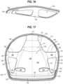
- An upper shellalso referred to as a carrier frame 100, has a central portion 102 overlying the inner ring 52 of the support ring and the lower support platform 30, and an outer ring 104 overlying the outer ring 74 of the support ring and the upper surface 34 of the support platform.
- the outer ring 104 and central portion 102 of the upper shellare coupled with at least two connectors, including a pair of front connectors 106 and a pair of intermediate connectors 108, which are curved with an upwardly facing concave curvature such that is rigid and resists outward/downward deflection/deformation.
- a pair of rear three-sided openings 109are defined between an inner edge of the outer ring 104, an edge of the central portion 102 and the edges of the connectors 108.
- the openings 109each have an inner side 111, a longer, outer curved side 113, with the sides 111, 113 converging along the rear of the opening 109 to define a nose 115, and a third side 117 extending along and defining the connector 108 and joining the sides 111, 113.
- a pair of front three-sided openings 119are defined between an inner edge of the outer ring 104, an edge of the central portion 102 and the edges of the connectors 108.
- the openings 119each have an inner side 121, a longer, outer curved side 123, with the sides 121, 123 converging along the front of the opening 119 to define a nose 125, and a third side 127 extending along and defining the connector 108 and joining the sides 121, 123.
- the outer ring 104has a front cross member 110 and a rear member 112 that are connected to side members 114.
- the outer ringhas a peripheral length defined around the perimeter thereof, with the length being fixed or maintained as a relative constant during recline of the seat.
- the outer ring 104defined by the side members 114, front cross member 110 and rear member 112, does not elongate during recline, or does not undergo elastic deformation along a tangent or length thereof in response to tensile forces, although the outer ring 104 is capable of bending or flexing as described in more detail below.
- the front cross member 110is spaced apart from a front edge 116 of the central portion 102, which define an elongated and laterally extending U-shaped opening 118 therebetween.
- Side slots 120allow for front portions 122 of the side members 114 to flex or bend such that the front cross member 110 may deflect when loaded by the user's legs, while the connectors 106, 108 provide greater rigidity to the outer ring 104.
- the connectors 106, 108overlie the connectors 78, 80, with openings 84 and 118, along with membrane 53, being aligned.
- the upper shellincludes pads 124 that overlie the pads 46.
- the upper shell 100is secured to the support platform with fasteners, including for example hooks and screws.
- the upper shell, or carrier frame 100is flexible, but stiffer than the support ring 48, and has a modulus of elasticity that is greater than the modulus of elasticity of the support ring, but the carrier frame is less stiff than, and has a modulus of elasticity less than a modulus of elasticity of the support platform 30.
- the upper shell, or carrier frame 100may be made of a flexibly resilient polymer material such as any thermoplastic, including, for example, nylon, glass-filled nylon, polypropylene, acetyl, or polycarbonate; any thermal set material, including, for example, epoxies; or any resin-based composites, including, for example, carbon fiber or fiberglass, thereby allowing the support platform to conform and move in response to forces exerted by a user.
- Suitable materialsmay be also be utilized, such as metals, including, for example, steel or titanium; plywood; or composite material including plastics, resin-based composites, metals and/or plywood.
- the intermediate connectors 108 of the upper shell 100may include an area of reduced thickness defining flex regions or flexing zones 155.
- the upper shell 100also may have an area of reduced thickness defining a flex region or flexing zone 153 that overlies the flex region 53 of the underlying support platform, located in front of the boss structure 48,
- the upper shell, or carrier frame 100has a body facing upper surface 126, a lower surface 128 opposite the upper surface 126 and a peripheral edge surface 130, or side edge face, extending between the first and second surfaces 126, 128.
- the peripheral edge surface 130is substantially planar and has a vertical orientation, although it should be understood that the edge surface may be curved, curvilinear, or non-planar, and/or may be oriented at angles other than a vertical plane.
- the carrier frame 100defines a concave cavity 132 with the outer ring defining a central opening 134.
- a peripheral groove 136is formed in and opens outwardly from the peripheral edge surface 130 or face.
- the groove 136extends around at least a portion of the carrier frame, and in one embodiment, extends continuously around the entire periphery of the carrier frame 100.
- the peripheral edge portion 92 of the support frame 62extends outwardly beyond the face 130 of the carrier frame as shown in FIGS. 7A-C .
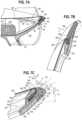
- the peripheral groove 136defines an insertion plane 137 oriented at an angle ⁇ relative to the peripheral edge surface 130, and relative to a gap G adjacent thereto.
- ⁇is greater than 0 degrees and less than 180 degrees, and is preferably between 30 and 120 degrees, and more preferably between 45 and 90 degrees .
- the insertion plane 137is preferably oriented relative to a landing portion 144, or tangent of a textile material 150 supported thereby, such that the insertion plane is parallel to the landing portion and tangent, or forms an angle ⁇ that is preferably between 135 and 180 degrees.
- the peripheral groove 136has a pair of spaced apart surfaces, e.g., upper and lower surfaces 138, 140, and a bottom 142 connecting the surfaces 138, 140.
- the upper surface 126 of the upper shellhas a landing portion 144, which is substantially horizontal, and an angled portion 146 that extends away from the landing portion and defines the cavity.
- the landing portion 144may have a width (W) approaching 0, with the landing portion defined simply by an upper corner of the edge surface 130.
- a textile material 150is secured to the carrier frame 100 across the central opening 134 such that it covers the concave cavity 132.
- the textile materialmay be a suspension material, or may cover a cushion supported by the support and/or carrier frames 64, 100.
- the textile materialcovers the upper surface 126 of the upper shell, and engages the landing portion 144.
- the textile material 150wraps around and engages a portion of the outer peripheral edge surface 130, and in particular an upper portion 152 of the peripheral edge surface extending between the groove 136 and the upper surface 126, or landing portion 144 thereof.
- a peripheral edge portion 154 of the textile material 150is coupled to the peripheral edge of the upper shell, for example with the edge portion 154 of the textile material being disposed in the groove 136.
- a stay 156(shown in FIG. 20 without the textile material), formed for example by a ring (e.g., a plastic or polyester), may be secured to the edge portion of the textile material, for example with adhesives, sewing/stitching, fasteners and other devices, or by forming a loop disposed around the stay.
- the stayhas one surface 158 facing and engaged with the textile material and an opposite surface 160 that remains uncovered.
- the stay 156 and edge portion 154 of the textile materialwhich is configured as a suspension material, are disposed in the groove 136 to secure the suspension material in tension across the opening.
- the stay 156is formed as a continuous ring having a fixed length, with the stay 156 being relatively inelastic and resistant to elongation along a length thereof, but which may be flexible and bendable so as to move with the side members 114 and outer ring 104 during recline of the seat.
- the exposed or uncovered surface 160 of the stay 156directly engages the surface 138 of the groove, without any textile material or other substrate disposed therebetween. The angular orientation of the groove 136 and stay 156 relative to the edge surface helps to ensure that the stay 156 does not become dislodged from the groove.
- the stay 156 and textile material 150are inserted into the groove 136 without any auxiliary fastening systems, such as adhesive or mechanical fasteners, but rather are engaged only by friction as the textile/suspension material is put in tension as explained hereinafter.
- the support frame 62includes a bottom wall 518 defining a body facing surface and a peripheral edge wall 520 having an outer surface 522.
- a lip 524, or catch, defined in one embodiment by a tab,extends laterally inwardly from the peripheral edge wall 520 and defines a channel 526 with the bottom wall.
- the lip or catchhas an engagement surface 528 that angles upwardly and inwardly from the peripheral edge wall while an upper surface of the wall is substantially horizontal.
- the upper surface of the lipis angled downwardly and inwardly, while the engagement surface 528 is substantially horizontal.
- a carrier frame 100has a body portion 530 with a bottom surface 532 overlying and engaging the bottom wall and an insert portion 534 that is received in the channel 526 and engages the engagement surface 528.
- the carrier framehas an upper surface 536 that is angled downwardly and inwardly, matching the top surface of the lip or catch, such that suspension material may deform against the angled surface.
- the insert portion 534is angled downwardly and outwardly so as to mate with the engagement surface. The orientation of the insert portion 534 facilitates installation as the insert portion may be more easily inserted into the channel when oriented at an angle such that the insert portion is underlying the lip 524.
- Tension applied by the textile material 150thereafter applies a moment to the carrier frame causing it to bear up against the bottom surface of the support frame and the engagement surface 528.
- a flexible edge member 162is coupled to the outer surface 522 of the peripheral edge wall of the support frame, with a lip portion 538 overlying a top surface of the support frame.
- the flexible edge member 162has an inner surface spaced apart from and facing inwardly toward the peripheral edge wall of the carrier frame, with the inner surface and the peripheral edge wall of the carrier frame defining a gap therebetween.
- a portion of the textile materialis disposed in the gap, with the textile material covering the body facing surface of the carrier frame.
- the carrier framehas a peripheral edge 540 facing outwardly, and includes a groove 542 opening laterally outwardly therefrom.
- the peripheral edge of the textile materialis secured to a stay 156, with the edge portion of the textile material and the stay disposed in the groove 542.
- the textile materialis made of an elastomeric woven or knitted material, and may be configured as a suspension material having heat-shrinkable yarns and heat shrinkable elastomeric monofilaments, which shrink in response to the application of energy, for example heat, whether applied by radiation or convection.
- a suspension materialhaving heat-shrinkable yarns and heat shrinkable elastomeric monofilaments, which shrink in response to the application of energy, for example heat, whether applied by radiation or convection.
- Various suitable suspension materialsare disclosed in U.S. Patent No. 7,851,390 , entitled "Two-Dimensional Textile Material, Especially Textile Fabric, Having Shrink Properties and Products Manufacture Therefrom".
- One commercially suitable heat-shrink suspension materialis a SHRINX fabric available from Krall + Roth, Germany.
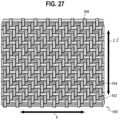
- the suspension materialis made from a fabric blank 500 having a plurality of heat shrinkable, elastic (elastomeric) threads 552, configured as monofilaments in one embodiment, running in a first, lateral direction 4, or warp direction, and a plurality of non-extensible threads 554, configured as yarns or monofilaments in various embodiments, running in the same lateral/warp direction 4.
- heat shrinkable, elastic threadse.g., monofilaments
- non-extensible threadse.g., monofilaments
- the heat shrinkable, elastic threads 552 and the plurality of non-extensible threads 554alternate 1:1 or 2:1, or are disposed side-by-side as shown in FIG. 27 , with various embodiments having a weave density of 4-10 elastic threads/cm, more preferably 7-9 elastic threads/cm, and a weave density of 8 elastic threads/cm in one embodiment.
- the ratio of threadsmay be altered, with more or less elastomeric threads than non-extensible threads.
- the elastic threadsare about 0.40 mm in diameter, with the understanding that the elastic threads may be made thicker or thinner depending on the desired spring rate.
- the weave densitymay be defined by a total cross-sectional area of the combined elastic thread(s) per cm (measured longitudinally), including for example elastic thread(s) having a combined cross-sectional area (whether a single thread or a plurality of threads) between 0.502 mm 2 /cm and 1.256 mm 2 /cm in various embodiments, more preferably between 0.879 mm 2 /cm and 1.130 mm 2 /cm, and a combined cross-sectional area of 1.005 mm 2 /cm in one embodiment.
- a plurality of yarn strands 556are interwoven with the elastomeric and non-extensible threads 552, 554 in the weft direction, or longitudinal direction 2, 2' in one embodiment.
- the non-extensible threads 554 and the yarn strands 556do not shrink when exposed to heat or energy, and are not elastomeric. Rather, the yarn strands 556 provide shape control to the overall suspension material in a final configuration after heat shrinking.
- the yarn strands 556may be made of various colors, e.g., blue, to provide color to the textile material. The overall color of the blank is thereby easily changed simply by introducing different yarns in the weft direction.
- the elastomeric threadsare preferably transparent or black.
- annular stay 156is secured to the fabric blank for example by sewing or with staples or other fastening systems, with the annular stay having first and second annular edges 558, 560.
- the annular stayis rotatable 180 degrees between a first configuration, wherein the first annular edge 558 is disposed radially inwardly from the second annular edge 560, and a second configuration, wherein the first annular edge 558 is disposed radially outwardly from the second annular edge 560 as shown in FIGS. 22 and 23 .
- the first annular edge 558 on opposite sides of the staydefine first and second dimensions therebetween in the first lateral direction 2, 2' when the stay is in the first and second configurations, wherein the first and second dimensions are substantially the same in one embodiment, meaning as the stay is rotated, the first annular edge remains stationary, albeit rotated 180 degrees.
- the stay 156includes open notches 157 in the second annular edge, which close and allow for the stay to be rotated from the first to second configurations.
- the fabric blank 500is initially configured with pockets of extra material at the corners to accommodate the rotation of the stays at those corners. After rotation, the stay 156 may be installed in the carrier frame 100, with the carrier frame and fabric then installed or coupled to the support frame 62, with the flexible edge 162 connected to the support frame 62 and disposed around the periphery of the textile material.
- the textile materialis wrapped around or covers a cushion or underlying substrate such as a plastic or metal web, which supports the user, with the edge of the textile material secured to the carrier frame as described herein.
- the textile material 150may be, but is not necessarily, put in tension around the cushion or across the opening 134.
- the flexible edge member 162is configured as a ring surrounding and coupled to the peripheral edge 92 of the support frame. It should be understood that the ring may be continuous, or that the flexible edge member may extend only partially around the periphery of the carrier frame 100.
- the flexible edge member 162extends upwardly from the support frame 64 and has an inner peripheral surface 164, or face, facing inwardly toward, and spaced apart from, the peripheral edge surface 130 of the carrier frame so as to form a gap G, for example and without limitation having a width of between 0.50 to 1.00 mm that is communication with the groove 136, meaning the groove and gap form a continuous, but non-linear slotted opening or pathway that receives the textile material 150.
- the inner surface 164is substantially planar and has a vertical orientation and extends in the Z direction, although it should be understood that the edge surface may be curved, curvilinear, or non-planar, and/or may be oriented at angles other than a vertical plane.
- the inner surface 164has substantially the same shape as the peripheral edge surface 130 such that the gap G is maintained constant, regardless of whether either surface or the gap G is linear.
- the gap Gis the same or slightly larger than the thickness of the textile material, which may have a thickness of about 0.75 to 1.00 mm, while in other embodiments, there is no gap (i.e.
- the gap Gis less than the thickness of the textile material, with the surfaces 130, 164 abutting, and/or squeezing or slightly compressing the textile material 150 therebetween.
- the inner surface 164faces and covers the groove 136 and textile material 150.
- the flexible edge member 162further entraps the stay 156 and textile material 150, thereby further helping to ensure that the stay 156 does not become dislodged from the groove 136.
- the flexible edge member 162is made of a thermoplastic olefin or thermoplastic elastomer, and may be made of the same material as the membrane 53, such that the flexible edge member may be compressed, for example if impacted.
- the flexible edge member 162has a greater resilience, or is more flexible and has a substantially lower modulus of elasticity less than the support frame 62, with a durometer in the shore D range, with one embodiment having a durometer of 80-90.
- the flexible edge member 162protects the textile material 150 from inadvertent impact and wear and has an upper surface 166 substantially flush with, or slightly lower than, an upper surface 168 of the textile material 150, thereby preventing snags and providing a pleasing appearance.
- the flexible edge member 162abuts, or is slightly spaced from, the portion of the textile material 150 disposed between the flexible edge member 162 and carrier frame 100.
- the flexible edge memberhas a groove 170, with the peripheral edge 92 of the support ring being disposed in the groove 170.
- the flexible edge member 162is over molded onto the peripheral edge 92 of the support frame 62, or support ring, and may be made of the same material as the membrane 53.
- the flexible edge membermay be secured to the support frame by friction, or with adhesives, mechanical fasteners, such as staples or screws, or combinations thereof.
- the geometry of the flexible edge member 162further promotes the protective and elastic properties thereof.
- the flexible edge member 162may be tapered from a first thickness T1 along the inner surface 164 to a second thickness T2 at an outermost peripheral edge thereof, with the thickness being measured parallel to the inner surface 164, or in substantially the Z direction.
- the flexible edge member 162 in cross-sectionhas a rounded nose shape.
- the flexible edge member 162may be compressed in response to a load applied in the X and/or Y directions, or may deflect in response to a load applied in the Z direction as shown in FIG. 7B .
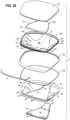
- an auxiliary support member 200shown as a cushion, is disposed between the upper surface 126 of the carrier frame 100 and a bottom surface 190 of the textile material 150, configured as a suspension material, or the space defined therebetween.
- An upper surface 202 of the auxiliary support member 200is spaced apart from the bottom surface 190 of the suspension material such that a gap G2 or space is defined therebetween when the suspension material is in an unloaded configuration (i.e., without a user disposed on the suspension material).
- the gap G2may be maintained as a constant, with the cushion having a contoured upper surface 202 that matches the contour of the bottom surface 190 of the suspension material.
- the gap G2is greater than 0 and less than 5 mm, and in one embodiment is 3 mm, such that the suspension material contacts the auxiliary support member 200 as soon as the user engages, or sits on, the suspension material.
- the auxiliary support member 200may have a generally trapezoidal shape in plan view that matches the shape of the central portion 102 of the carrier frame or the support platform 30.
- the auxiliary support member 200extends forwardly to cover the opening 118 and support the thighs of the user.
- the auxiliary support membermay be made of foam.
- the auxiliary support member 200may be secured to the support platform 30 and/or carrier frame 100 with fasteners, including mechanical fasteners such as screws or adhesive.
- the auxiliary support member 200has a bottom substrate 201, for example a plastic or wood sheet, that may be engaged with fasteners and which is connected to, or embedded in, an upper foam cushion 203 as shown in FIG. 20 .
- the load applied to the suspension material 150causes it to deflect downwardly toward the auxiliary support member 200. If the load is such that the suspension material deflects across the distance G2 and comes into contact with the auxiliary support member 200, the auxiliary support member 200 thereafter may absorb the additional loading and support the user.
- the auxiliary support member 200abuts and supports the textile material in an unloaded condition.
- the textile materialmay simply cover a cushion, which fills the space of the cavity 132 of the carrier frame, with the textile material forming an upholstery cover over the top of the cushion.
- a method of manufacturing or assembling a body support member 10includes positioning and securing the auxiliary support member 200 on top of the carrier frame 100. The method further includes disposing the peripheral edge portion 154, 252 of the textile material 150, 234 into the peripheral groove 136, 244 formed in the peripheral edge surface 130, 246 of the frame, with the stay 156, 250 engaging one surface of the groove. As the stay 156, 250 is rolled over for insertion into the groove, the suspension material covers the portion of the peripheral edge surface 130, 246 between the groove and the upper (or front) surface 126 (i.e., body-facing first surface of the frame).
- the carrier frame 100, 242is then connected to the support frame 62, 236, which has a flexible edge member 162, 240 secured thereto for example by way of support ring 48.
- the flexible edge member 162may first be connected to the carrier frame 100, for example by way of the support ring 48, with those components thereafter being coupled to the support platform 30.
- the flexible edge member 162, 240is secured to the support frame 62, or support ring 48, by over molding the flexible edge member 162 onto the peripheral edge 92 of the support frame/support ring.
- the flexible edge membermay be secured in other ways, including with adhesive or mechanical fasteners.
- Energyfor example thermal energy or heat applied by radiation or convection, may be applied to the suspension material 150, 234, causing the suspension material to shrink and create tension therein.
- the energymay be applied to the suspension material either before or after the carrier frame 100, 242 is secured to the support frame 62, 212.
- the suspension materialshrinks, the suspension material is put in tension across the opening 134 and the stays 250, 156 are anchored in the grooves 136, 244.
- the backrest assembly 6includes a back frame 210 and a back support 212, otherwise referred to as a support frame.
- the back frameis relative rigid, meaning it does not substantially flex/bend or otherwise elastically deform during recline.
- the back frame 210has a lower portion 214 that is connected to the rear portion of the tilt control assembly 18.
- the lower portion 214, or lower support arm,extends generally horizontally in the longitudinal direction 2' along a central axis of the seating structure.
- the back frame 210is pivotable rearwardly relative to the base 12 during recline.
- a transition portion 216which is a curved and defines a rearwardly facing convex bow shape in one embodiment, extends rearwardly and upwardly from the lower portion 214.
- a pair of laterally spaced uprights 218extend upwardly from the transition portion 216.
- the back frame 210further includes an upper cross member 220 extending between and connecting upper ends of the uprights 218, with the cross member 220, upright 218 and lower portion 214 defining a central opening.
- the back support 212otherwise referred to as a support frame, is flexible, and includes flex regions 225, 233 allowing it to bend and deflect in response to the user reclining in the body support structure.
- the back support, or support frame 212includes a pair of laterally spaced uprights 222, each having a forwardly facing convex bow shaped portion 223 at a first location proximate a lumbar region of the back support, with each bow shaped portion including and defining a flex region.
- a bottom portion 224extends between and connects the uprights.
- the back support 212further includes a lower portion or support arm 226 that extends forwardly from the bottom portion, with the support arm or lower portion coupled to the control assembly.
- the uprights 222 of the back supportare coupled to the uprights 218 of the back frame with connectors 228.
- the back support 212is pivotable with the back frame 210.
- the uprights 218, 222may be pivotally connected with a mechanical pivot joint, including for example the pivot structure disclosed in U.S. Patent No. 9,826,839 .
- the back support 212includes an upper member 230 extending between and connected to upper ends of the pair of second uprights 222, and the bottom portion 224 extends between and is connected to the lower ends of the pair of second uprights.
- the upper member 230, uprights 222 and the bottom portion 224define a central opening 232.
- a suspension material 234is stretched across the central opening 232 and is secured to the back support 212 in a similar fashion as the seat.
- the upper member 230, the bottom portion 224 and the pair of second uprights 222define a support frame 236 having a peripheral edge 238 as shown in FIG. 7B .
- a flexible edge member 240is secured to the peripheral edge of the upper member 230 and uprights 222, or along a face of the bottom portion 224.
- a carrier frame 242is coupled to the support frame 236 and includes a peripheral groove 244 facing outwardly from a peripheral edge surface or face 246, oriented horizontally between the front and rear surfaces of the carrier frame, which is spaced apart from an inner surface or inwardly facing face 248 of the flexible edge member 240 and defines a space or gap G therebetween as disclosed above with respect to the seat assembly.
- the groove 244opens outwardly from the carrier frame 242 along the peripheral edge 246 thereof.
- the suspension material 234includes at least one stay 250, configured as a ring in one embodiment, secured along a peripheral edge portion 252 of the suspension member, wherein the at least one stay is disposed in the groove 244.
- the stay 250may be held by friction alone, without any auxiliary support material such as adhesive.
- the staydirectly 250 engages one surface, e.g., a front surface, of the groove 244, while the fabric engages the rear surface. In this way, as with the seat, the stay engages the surface of the groove 244 closest to the surface of the carrier frame covered by the fabric.
- the stay 250is formed as a continuous ring having a fixed length, with the stay 250 being relatively inelastic and resistant to elongation along a length thereof, but which may be flexible and bendable.
- the support frame 236includes a rear wall 800 defining a body facing surface 802, an outer peripheral edge wall 804 having an outer surface 806 and an inner peripheral edge 808 wall, with the walls 804, 808 defining a forwardly facing channel 810.
- a lip 812, or catchextends laterally inwardly from the outer peripheral edge wall and defines a channel 816 with the rear wall 800, with a rear surface of the lip defining an engagement surface 814.
- a carrier frame 820has a body with a rear flange 822 defining a rear surface overlying and engaging the rear wall and an insert portion 824, defined by a plurality of tabs 825 spaced apart around the periphery of the carrier frame 820 in one embodiment.
- the insert portion 824is received in the channel 816 and engages the engagement surface 814.
- the carrier frame 820further includes upper and lower pairs of lugs 827 that are aligned with lug 829 on the support frame 236, with fasteners 831 securing the lugs 827, 829 to further connect the support frame 236 and carrier frame 820.
- the carrier frame 820includes a second flange 826 that forms an outwardly facing groove 830 with the flange 822 and defines an outer peripheral edge wall 827.
- the flange 826extends across the channel 810 with an edge 832 positioned adjacent the inner peripheral edge wall 808 and closing the channel.
- a flexible edge member 240is coupled to the outer surface of the peripheral edge wall 804 of the support frame, with a lip portion overlying a top surface of the support frame.
- the flexible edge member 240has an inner surface spaced apart from and facing inwardly toward the peripheral edge wall of the carrier frame, with the inner surface and the peripheral edge wall 827 of the carrier frame defining a gap therebetween. A portion of the textile material is disposed in the gap, with the textile material covering the peripheral edge wall 827 and body facing surface of the carrier frame. The peripheral edge of the textile material is secured to a stay 156, with the edge portion of the textile material and the stay disposed in the groove 830.
- the carrier frame 242may be secured to the support frame with the overlapping tabs 815, 825 and fasteners 831, including mechanical fasteners and/or adhesive.
- a user 101may sit in the body support structure 10.
- the suspension materialmay engage the upper surface 202 of the auxiliary support member 200, or cushion 203, which thereafter assists in absorbing the load of the user.
- the side portionsare inwardly deflectable a first amount from a first unloaded configuration to a first loaded configuration in response to a load applied to the elastic material, and define in essence a first spring to absorb the load of the user.
- the elastic textile material, or suspension material 150, coupled to the side portions 114 across the openingis downwardly deflectable a second amount from a second unloaded configuration to a second loaded configuration in response to the load applied thereto, and defines a second spring to absorb the load of the user.
- the deflection of the frame, or side portions, and the deflection of the suspension materialact in combination to provide a first amount of support to the user.
- the cushion disposed beneath the textile materialengages and provides auxiliary support to the elastic material when the first and second amounts of deflection, or first amount of support, result in the elastic material contacting the cushion, which defines a third spring to absorb the load of the user.
- the upper surface of the cushion 203is spaced apart from the textile material when the side portions 114 are in the first unloaded configuration and the elastic suspension material 150 is in the second unloaded configuration.
- the flexible support/carrier frame, elastic suspension material and cushionprovide first, second and third amounts of resilient support to a user engaging and supported by the textile material, with the suspension material and flexible frame working in combination.
- the elastic suspension material 150is downwardly deflectable a first amount in response to the deflection of the at least one side portion 114, or both side portions depending on where the load is applied.
- the resilience and deflection of the side portions 114is primarily a function of the deflection of the at least one connector 80, 108 extending between the central portion 102 and support platform 30 and the side portions 114.
- the connectors 80, 108extend upwardly and outwardly from the central portion, and curved with an upwardly facing concave surface such that is rigid and resists outward/downward deflection/deformation.
- the connectors 80, 108includes a pair of opposite side connectors that are inwardly deflectable from the first unloaded configuration to the first loaded configuration in response to the load applied to the elastic material.
- the user 101may recline, with the tilt control assembly 18 providing for the seat and/or backrest assemblies 8, 6 to move rearwardly, whether by pivoting, rotation, translation or a combination thereof, for example by way of a four-bar mechanism including links 8, 23, 25 and 33.
- the support platform 30 and the carrier frame 100flex or bend about the flex regions 53, 153, such that the rear portion 121 of the seat assembly, and rear portion of the support platform, rotates or deflects downwardly relative to the front portion 123 of the seat assembly, and front portion of the support platform, about the flex region.
- the intermediate connectors 108flex or bend upwardly about flex regions 155, such that the side member 114 of the outer ring 104 move upwardly relative to the support platform and inwardly toward each other to a new configuration or shape of the side member 114', with the textile material 150 assuming a more concavely configured textile material 150' that slightly hammocks and hugs the user.
- the connectors 108 and outer ring 104deflect, the overall length of the outer ring 104 is maintained, and is not increased.
- the support ring 48is sufficiently flexible and compliant that the support ring 48 does not interfere with the flexing of the carrier frame 100, but rather provides a decorative and tactile skin covering a bottom surface of the carrier frame. If needed, the support ring 48 may also be provided with flex regions to allow such flexing.
- the side members 114 and connectors 108Due to the geometry of the seat assembly, including the configuration of the outer ring 104, the geometry (e.g., upwardly concavity) of the curved connectors 108, the concavity of the carrier frame 100, and the configuration of the openings 109, 119, the side members 114 and connectors 108 are relatively rigid, and resist/avoid a downward deformation, in response to downward load applied along the sides of the seat at the perimeter of the chair.
- the four-bar linkageprovides a weight activated system, meaning the weight of the user is taken into account when reclining since the increase in potential energy is offset by the kinetic energy required to recline.
- the four-bar mechanismwill provide more resistance to a heavier user and automatically counterbalance the user.
- the amount of reclinemay be limited by the recline limiter, while energy may supplied to boost the resistance to recline and return the body support assembly to the upright, nominal position.
Landscapes
- Chair Legs, Seat Parts, And Backrests (AREA)
- Mattresses And Other Support Structures For Chairs And Beds (AREA)
- Chairs For Special Purposes, Such As Reclining Chairs (AREA)
- Chairs Characterized By Structure (AREA)
Description
- This application claims the benefit of
U.S. Provisional Application No. 62/808,579, filed February 21, 2019 U.S. Provisional Application No. 62/947,914, filed December 13, 2019 - The present application relates generally to a body support assembly, for example a chair, and in particular to a body support member.
- Chairs, and in particular office chairs, may have a body support member configured with a suspension material, such as a mesh fabric, that is stretched across a frame. Such suspension materials conform to the body of the user, providing micro compliance along with improved air circulation, and the attendant cooling benefit. Typically, the frame must be rigid in order to maintain an appropriate level of tension in the suspension material. Such rigidity may limit, however, the flexibility of the body support member, and introduce unforgiving pressure points around the perimeter of the frame. In addition, suspension materials installed on a seat of a chair are typically required to sustain higher tensions due to the load being applied thereto by a seated user, which may exacerbate the limited flexibility and rigidity of the supporting structure.
- While various mechanical systems, such as lumbar supports and tilt control mechanisms, may be introduced to mitigate the limited flexibility and provide additional adjustment capabilities, such systems are relatively expensive to manufacture, require additional maintenance, are susceptible to wear and tear over time, and may not be appropriately exploited by the user due to the requirement for individual adjustments. In addition, such tilt mechanisms typically include one or more rigid links, and mechanical connections, which are rigid and non-compliant, which result in a more rigid and less forgiving ride, and which may lead to a less desirable user experience. Conversely, systems relying on the materiality of the seating structure to introduce the appropriate kinematics and flexibility may not be suitable to support a suspension material. While body support surfaces may be defined by one or more foam cushions, foam materials may limit air circulation and often do not provide localized support. In addition, body support members configured with plastic shells, supported for example by peripheral frames, typically do not provide a comfortable body-conforming support surface. A body support member is known for example from
US 6 910 741 B2 . - The present invention is defined by the following claim, and nothing in this section should be considered to be a limitation on that claim.
- The present invention provides a body support member as defined in claim 1.
- The foregoing paragraphs have been provided by way of general introduction, and are not intended to limit the scope of the claims presented below. The various preferred embodiments, together with further advantages, will be best understood by reference to the following detailed description taken in conjunction with the accompanying drawings.
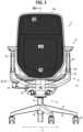
FIG. 1 is a perspective view of one embodiment of a body support assembly.FIG. 2 is a right side view of the body support assembly shown inFigure 1 , with the left side view being a mirror image thereof.FIG. 3 is front view of the body support assembly shown inFigure 1 .FIG. 4 is a rear view of the body support assembly shown inFigure 1 .FIG. 5 is a bottom view of the body support assembly shown inFigure 1 .FIG. 6 is a top view of the body support assembly shown inFigure 1 .FIGS. 7A , B and C are partial cross-sectional views of a body support member according to the invention.FIG. 8 is a partial perspective view of a seat without the textile material shown for the sake of illustrating the underlying components.FIG. 9 is a top view of one embodiment of a seat support structure without the textile material or carrier frame shown for the sake of illustrating the underlying components.FIG. 10 is a bottom perspective view of one embodiment of a lower seat support platform.FIG. 11 is a right side view of the support platform shown inFigure 10 with a left side view being a mirror image thereof.FIG. 12 is a rear view of the support platform shown inFigure 10 .FIG. 13 is a top view of the support platform shown inFigure 10 .FIG. 14 is a left side view of one embodiment of a support ring, with a right side view being a mirror image thereof.FIG. 15 is a top view of the support ring shown inFigure 14 .FIG. 16 is a side view of one embodiment of an upper seat shell.FIG. 17 is a top view of the upper shell shown inFigure 16 .FIG. 18 is a schematic side view illustrating flexing of the seat assembly during recline.FIG. 19 is a schematic front view illustrating flexing of the seat assembly during recline.FIG. 20 is an exploded view of a seat assembly, comprising the body support member according to the invention.FIG. 21 is a schematic view showing a four-bar mechanism supporting a seat assembly.FIG. 22 is a partial, cross-sectional view of a front portion of a seat assembly.FIG. 23 is a partial, cross-sectional view of a side portion of a seat assembly.FIG. 24 is a partial, cross-sectional view of a top portion of a back support.FIG. 25 is a partial, cross-sectional view of a side portion of a back support.FIG. 26 is a flow diagram illustrating the assembly of the seat assembly.FIG. 27 is a partial, plan view of a textile material installed on the seat assembly and back support.FIGS. 28A-D are a bottom, top, exploded and enlarged cross-sectional views showing the connection between a front link and the seat assembly.FIG. 29 is a partial view of one embodiment of a stay.FIG. 30 is a partial cut-away view of a seat assembly.- It should be understood that the term "plurality," as used herein, means two or more. The term "longitudinal," as used herein means of or relating to a length or lengthwise
direction 2, 2', for example a direction running from the bottom of a backrest assembly 6 to the top thereof, or vice versa, or from the front of aseat assembly 8 to the rear thereof, or vice versa. The term "lateral," as used herein, means situated on, directed toward or running in a side-to-side direction 4 of abody support assembly 10, shown in one embodiment as an office chair including the backrest assembly 6 andseat assembly 8. It should be understood that the body support assembly may be configured as any structure that supports a body, including without limitation automotive, aircraft and mass-transit seating, beds, home furnishings (including sofas and chairs), and other similar and suitable structures. In one embodiment of a backrest assembly disclosed below, a lateral direction 4 corresponds to a horizontal direction and alongitudinal direction 2 corresponds to a vertical direction, while in one embodiment of a seat assembly, the longitudinal direction 2' corresponds to a horizontal direction. The lateral direction 4 may be referred to as an X direction, while thelongitudinal direction 2, 2' refers to a Y direction and a Z direction is orthogonal to the body support surface of both the backrest andseat assemblies 6, 8. - The term "coupled" means connected to or engaged with, whether directly or indirectly, for example with an intervening member, and does not require the engagement to be fixed or permanent, although it may be fixed or permanent. The terms "first," "second," and so on, as used herein are not meant to be assigned to a particular component so designated, but rather are simply referring to such components in the numerical order as addressed, meaning that a component designated as "first" may later be a "second" such component, depending on the order in which it is referred. It should also be understood that designation of "first" and "second" does not necessarily mean that the two components or values so designated are different, meaning for example a first direction may be the same as a second direction, with each simply being applicable to different components. The terms "upper," "lower," "rear," "front," "fore," "aft," "vertical," "horizontal," "right," "left," and variations or derivatives thereof, refer to the orientations of an exemplary
body support assembly 10, shown as a chair inFIGS. 1-6 , from the perspective of a user seated therein. The term "transverse" means non-parallel. The term "outwardly" refers to a direction facing away from a centralized location, for example the phrase "radially outwardly" refers to a feature diverging away from a centralized location, for example the middle or interior region of a seat or backrest, and lies generally in the X Y plane defined by the lateral andlongitudinal directions 2, 2', 4. It should be understood that features or components facing or extending "outwardly" do not necessarily originate from the same centralized point, but rather generally emanate outwardly and exteriorly along a non-tangential vector. Conversely, the term "inwardly" refers to a direction facing toward the centralized or interior location. - The term "textile material" refers to a flexible material made of a network of natural or artificial fibers (yarn, monofilaments, thread, etc.). Textile materials may be formed by weaving, knitting, crocheting, knotting, felting, or braiding. Textile materials may include various furniture upholstery materials, which may be used for example to cover a foam cushion, and/or suspension materials, which may be stretched or put in tension across an opening to support a user.
- Referring to
FIGS. 1-6 , thebody support assembly 10 is shown as including atilt control assembly 18, also referred to as a lower support structure, abase structure 12 and the backrest andseat assemblies 6, 8. In one embodiment, thebase structure 12 includes aleg assembly 14 and asupport column 16 coupled to and extending upwardly from the leg assembly. Thetilt control assembly 18 is supported by and coupled to a top of thesupport column 16. The leg assembly may alternatively be configured as a fixed structure, for example a four legged base, a sled base or other configuration. In one embodiment, thesupport column 16 may be height adjustable, including for example and without limitation a telescopic column with a pneumatic, hydraulic or electro-mechanical actuator. Theleg assembly 14 includes a plurality ofsupport legs 22 extending radially outwardly from ahub 24 surrounding the support column. Ends of each support leg may be outfitted with a caster, glide or otherfloor interface member 20. - In the embodiment of
FIGS. 1-6 , a pair ofarmrest assemblies 26 are coupled to thetilt control assembly 18. Various user interface controls 28 are provided to actuate and/or adjust the height of the seat, including for example an actuation lever pivotally coupled to the armrest assembly, or to control the tension and/or return force of thetilt control assembly 18. - Referring to
FIGS. 1-6 and28A-D , the backrest andseat assemblies 6, 8 are operably coupled to thetilt control assembly 18, or lower support structure, which controls the movement thereof, for example during recline. One embodiment of a suitable tilt control assembly is disclosed inU.S. Patent No. 9,826,839 - In other embodiments, the tilt control assembly include integrally formed
links U.S. Pub. No. 2016/0296026 A1 , entitled "Seating Arrangement," and inU.S. Pub. No. 2018/0352961 , entitled "Seating Arrangement and Method of Construction". - For example, the
tilt control assembly 18 may be configured as a four-bar mechanism as shown inFIG. 21 , with a bottom, orbase link 33 connected to thebase structure 12 at a first location, and front andrear links seat assembly 8. The base, front andrear links rear links base link 33 atflex regions rear links seat assembly 8 atflex regions flex regions flex region 53 is formed in thesupport platform 30 portion of the seat assembly. Thevarious flex regions - In operation, a user can move or recline the backrest and
seat assemblies 6, 8 from an upright position to a reclined position by flexing the four bar mechanism, including portions of the seat assembly. It is contemplated that the four-bar linkage arrangement as used and described herein is inclusive of linkage arrangements comprising additional linkage members, such as five-bar linkage arrangements, six-bar linkage arrangements, and the like. In various embodiments, the thickness of one ormore links seat links flex regions rear link 25 to achieve the desired flexibility of the four-bar linkage. In some embodiments, the various links may be more flexible in a particular portion or localized area of the link such that the links are generally flexible in the localized area and are generally not flexible or less flexible in any other area of the link. It is noted that the relative areas of reduced thickness may extend along a short distance or the majority of the length of the associated link depending upon the support and bending characteristics desired. - Referring to
FIGS. 1-7C ,8-25 and28A-D , theseat assembly 8 is operably coupled to thetilt control assembly 18 and supports aseating surface 28. The seat has opposite sides spaced apart in a lateral direction and a front and rear spaced apart in a first longitudinal direction. The seat assembly includes alower support platform 30 having aperipheral edge 32, anupper surface 34 and alower surface 36. In one embodiment, the lower support platform has a generally isosceles trapezoidal shape in plan view (seeFIG. 13 ) with afront edge 38,rear edge 40 and side edges 42 joining the front and rear edges. The rear edge is shorter than the front edge. Theperipheral edge 32 may be stepped, meaning aperipheral edge portion 66 thereof is thinner than acentral portion 68 thereof. - The
support platform 30 has a pair of laterally spacedpads 44 positioned at a forward portion of the support platform. As shown inFIGS. 28A-D , theplatform 30 includes a raisedportion 970 defining arecess 974 and anopening 972. The pads are each defined as ahinge portion 976 with afront edge 978 secured to afront edge 980 of the platform defining theopening 972 in the platform. The hinge portion may be formed by overmolding a more flexible material to the support platform. Thehinge portion 976 extends rearwardly in the opening with arear edge 982 spaced apart from arear edge 984 of the platform defining theopening 972. Each of thepads 44 includes at least one mounting component, shown asopenings 46 shaped and dimensioned to receive mounting members (e.g. fasteners or studs 988) for securing the platform to the tilt control assembly, which may include aflange 990 extending forwardly from thelink 23 to support the platforms. Theflange 990 is received in therecess 972 and includes bosses extending upwardly into theopenings 46 such that theflange 990 may be secured to a bottom surface of the pad, and hingeportion 976 in particular, with the plurality offasteners 988. Theflexible hinge portion 976 defines theflex region 27. The mounting component, and connection to thelink 23, allows for pivoting of the support platform and thefront link 23 relative to thebase link 33 about aflex region 29, and for pivoting of theseat assembly 8 relative to thefront link 23 aboutflex region 27, executed in both cases for example by elastic deformation or bending of portions of the front links at theflex regions hinge portion 976. At the same time, the spacing between the pads, and front links, provides relative stability to the front portion of the seat, which resists rotation or torsional movement about a longitudinal axis. A boss structure 49 extends downwardly from a rear portion of the support platform. The boss structure 49 defines at least one mounting component that is connected to thetilt control assembly 18, and/or defines a portion of arear link 25 forming in part the tilt control assembly and allows for pivoting of the support platform and therear link 25 relative to thebase link 33 about aflex region 31, which may be executed for example by elastic deformation or bending of portions of thebase link 33 atflex region 31. In one embodiment, the boss structure 49 has a tubular configuration defining a cavity that surrounds or receives an insert portion of therear link 25, configured with features from the connector 479, the 219. The centrally located rear link, which is the only support for the rear of the seat, allows for rotation or torsional movement of the rear of the seat relative to the front of the seat about a longitudinal axis, with the rotation or torsional movement of the front being restricted as previously explained. Thesupport platform 30 has a generally concaveupper surface 34, with front andrear portions - The support platform may be made of a flexibly resilient polymer material such as any thermoplastic, including, for example, nylon, glass-filled nylon, polypropylene, acetyl, or polycarbonate; any thermal set material, including, for example, epoxies; or any resin-based composites, including, for example, carbon fiber or fiberglass, thereby allowing the support platform to conforms and move in response to forces exerted by a user. Other suitable materials may be also be utilized, such as metals, including, for example, steel or titanium; plwood; or composite material including plastics, resin-based composites, metals and/or plywood. The support platform may have strategically positioned tensile substrates, made for example of glass reinforced tape, to accommodate bending and deformation of the structure. Strategic locations on the lower support platform also are provided with specific geometries that allow for predetermined deformations and define "flex regions," otherwise referred to as "flex joints," or virtual pivot locations.
- For example, the support platform may include an area of reduced thickness defining a laterally extending flex region or flexing
zone 53 located in front of the boss structure 49, which divides or bifurcates the support platform into front and rear portions, which may have different lengths or dimensions, with the rear portion being downwardly deflectable relative to the front portion during recline as the flex region bends. The portion of the support platform extending between theflex region 53 and theflex region 27 defines a link of a four-bar mechanism, while a portion of the support platform rearward of theflex region 53 defines in part a portion of therear link 25. It is noted that the relative areas of reduced thickness may extend along a short distance or the majority of the width of the support platform depending upon the support and bending characteristics desired. The phrase "flex region" refers to a portion of the structure that allows for flexing or bending in the designated region, thereby allowing or providing for relative movement (e.g., pivoting) of the component or structure on opposite sides of the flex region, thereby defining a virtual pivot location, for example a horizontal pivot axis, with the understanding that the virtual pivot axis may move during the flexing, rather than being defined as a hard fixed axis. The various configurations and materials of the support platform may correspond to the configuration and materials of various components as shown and disclosed inU.S. Pub. No. 2016/0296026 A1 , entitled "Seating Arrangement," and inU.S. Pub. No. 2018/0352961 , entitled "Seating Arrangement and Method of Construction". - A
support ring 48 has aninner ring 50 with an interiorperipheral edge 52 that defines acentral opening 54. The interiorperipheral edge 52 surrounds and is coupled to the outerperipheral edge 32 of the support platform, namely therear edge 40,front edge 38 and side edges 42, of thesupport platform 30, which is received in theopening 54. Theinner ring 50 has a trapezoidal shape defined by afront member 56, arear member 58 and a pair ofside members 60 defining theopening 54. The interiorperipheral edge 52 may be stepped, meaning aperipheral edge portion 70 thereof is thinner than acentral portion 72 thereof, with theedge portion 70 overlapping and mating with theedge portion 66 of the lower support platform. As shown inFIG. 7A , theedge portion 70 is positioned above theedge portion 66, with an upper surface of theperipheral edge 52 lying flush with the upper surface of thesupport platform 30. Theedge portions support platform 30 andsupport ring 48 in combination define asupport frame 62. - In one embodiment, the
support ring 48 further includes anouter ring 74 withside members 76 joined toside members 60 of the inner ring with a pair offront connectors 78 and a pair ofintermediate connectors 80. A pair of rear three-sided openings 81 are defined between an inner edge of theouter ring 74, an edge of the side member and the edges of theconnectors 80. Theopenings 81 each have aninner side 85, a longer, outercurved side 87, with thesides opening 81 to define anose 89, and athird side 91 extending along and defining theconnector 80 and joining thesides sided openings 83 are defined between an inner edge of theouter ring 74, an edge of theside member 60 and the edges of theconnectors 80. Theopenings 83 each have aninner side 93, a longer, outercurved side 95, with thesides 93. 95 converging along the front of theopening 83 to define anose 99, and athird side 97 extending along and defining theconnector 80 and joining thesides - It should be understood that in one embodiment, the
intermediate connectors 80 may be omitted. The outer ring has afront cross member 82 and arear member 58, which it shares with the inner ring, and which are connected to theside members 76. Thefront cross member 82 is spaced apart from thefront member 56, which define an elongated and laterally extendingU-shaped opening 84 therebetween. Aflexible membrane 55 covers theopening 84, is connected to the support ring around the perimeter of the opening, and maintains the spacing between thecross member 82 andfront member 56 when thecross member 82 flexes relative to thefront member 56, for example when undergoing a load applied by a user's thighs. Themembrane 55 may also serve as a limiter by limiting the amount of deflection of thecross member 82 when the load is applied thereto. Themembrane 55 may be made of urethane, and may be over molded on thesupport ring 48 to cover theopening 84.Side slots 86 allow forfront portions 88 of theside members 76 to flex or bend such that thefront member 82 may deflect when loaded by the user's legs, while theconnectors outer ring 74. An outerperipheral edge 90 is stepped, meaning aperipheral edge portion 92 thereof is thinner than thecentral portion 72 thereof. A pair oflugs 94 extend downwardly from the inner ring and are disposed along the sides of the boss structure, where they are supported by thetilt control assembly 18. Thesupport ring 48 extends radially outwardly from thelower support platform 30. The support ring, including the outer ring, the inner ring and connectors, defines anupper surface 96 and aconcave cavity 98. Thesupport ring 48 is made of a compliant flexible material, which is configured to position and hold theflexible edge member 162, described in more detail below. Thesupport ring 48 is less stiff than the support platform, and has a modulus of elasticity that is less than a modulus of elasticity of the support platform. The support ring may be made, for example, of polyester urethane, or a thermoplastic polyester elastomer. - An upper shell, also referred to as a
carrier frame 100, has acentral portion 102 overlying theinner ring 52 of the support ring and thelower support platform 30, and anouter ring 104 overlying theouter ring 74 of the support ring and theupper surface 34 of the support platform. Theouter ring 104 andcentral portion 102 of the upper shell are coupled with at least two connectors, including a pair offront connectors 106 and a pair ofintermediate connectors 108, which are curved with an upwardly facing concave curvature such that is rigid and resists outward/downward deflection/deformation. - A pair of rear three-
sided openings 109 are defined between an inner edge of theouter ring 104, an edge of thecentral portion 102 and the edges of theconnectors 108. Theopenings 109 each have aninner side 111, a longer, outercurved side 113, with thesides opening 109 to define anose 115, and athird side 117 extending along and defining theconnector 108 and joining thesides sided openings 119 are defined between an inner edge of theouter ring 104, an edge of thecentral portion 102 and the edges of theconnectors 108. Theopenings 119 each have aninner side 121, a longer, outercurved side 123, with thesides opening 119 to define anose 125, and athird side 127 extending along and defining theconnector 108 and joining thesides - The
outer ring 104 has a front cross member 110 and arear member 112 that are connected to sidemembers 114. The outer ring has a peripheral length defined around the perimeter thereof, with the length being fixed or maintained as a relative constant during recline of the seat. In other words, in one embodiment, theouter ring 104, defined by theside members 114, front cross member 110 andrear member 112, does not elongate during recline, or does not undergo elastic deformation along a tangent or length thereof in response to tensile forces, although theouter ring 104 is capable of bending or flexing as described in more detail below. The front cross member 110 is spaced apart from afront edge 116 of thecentral portion 102, which define an elongated and laterally extendingU-shaped opening 118 therebetween. Side slots 120 allow forfront portions 122 of theside members 114 to flex or bend such that the front cross member 110 may deflect when loaded by the user's legs, while theconnectors outer ring 104. Theconnectors connectors openings membrane 53, being aligned. The upper shell includespads 124 that overlie thepads 46. Theupper shell 100 is secured to the support platform with fasteners, including for example hooks and screws. - The upper shell, or
carrier frame 100, is flexible, but stiffer than thesupport ring 48, and has a modulus of elasticity that is greater than the modulus of elasticity of the support ring, but the carrier frame is less stiff than, and has a modulus of elasticity less than a modulus of elasticity of thesupport platform 30. The upper shell, orcarrier frame 100, may be made of a flexibly resilient polymer material such as any thermoplastic, including, for example, nylon, glass-filled nylon, polypropylene, acetyl, or polycarbonate; any thermal set material, including, for example, epoxies; or any resin-based composites, including, for example, carbon fiber or fiberglass, thereby allowing the support platform to conform and move in response to forces exerted by a user. Other suitable materials may be also be utilized, such as metals, including, for example, steel or titanium; plywood; or composite material including plastics, resin-based composites, metals and/or plywood. - The
intermediate connectors 108 of theupper shell 100 may include an area of reduced thickness defining flex regions or flexingzones 155. Theupper shell 100 also may have an area of reduced thickness defining a flex region or flexingzone 153 that overlies theflex region 53 of the underlying support platform, located in front of theboss structure 48, - The upper shell, or
carrier frame 100, has a body facingupper surface 126, alower surface 128 opposite theupper surface 126 and aperipheral edge surface 130, or side edge face, extending between the first andsecond surfaces peripheral edge surface 130 is substantially planar and has a vertical orientation, although it should be understood that the edge surface may be curved, curvilinear, or non-planar, and/or may be oriented at angles other than a vertical plane. Thecarrier frame 100 defines aconcave cavity 132 with the outer ring defining acentral opening 134. - A
peripheral groove 136 is formed in and opens outwardly from theperipheral edge surface 130 or face. Thegroove 136 extends around at least a portion of the carrier frame, and in one embodiment, extends continuously around the entire periphery of thecarrier frame 100. Theperipheral edge portion 92 of thesupport frame 62 extends outwardly beyond theface 130 of the carrier frame as shown inFIGS. 7A-C . Theperipheral groove 136 defines aninsertion plane 137 oriented at an angle α relative to theperipheral edge surface 130, and relative to a gap G adjacent thereto. In various embodiments, α is greater than 0 degrees and less than 180 degrees, and is preferably between 30 and 120 degrees, and more preferably between 45 and 90 degrees . Defined another way, theinsertion plane 137 is preferably oriented relative to alanding portion 144, or tangent of atextile material 150 supported thereby, such that the insertion plane is parallel to the landing portion and tangent, or forms an angle β that is preferably between 135 and 180 degrees. Theperipheral groove 136 has a pair of spaced apart surfaces, e.g., upper andlower surfaces surfaces upper surface 126 of the upper shell has alanding portion 144, which is substantially horizontal, and anangled portion 146 that extends away from the landing portion and defines the cavity. Thelanding portion 144 may have a width (W) approaching 0, with the landing portion defined simply by an upper corner of theedge surface 130. - A
textile material 150 is secured to thecarrier frame 100 across thecentral opening 134 such that it covers theconcave cavity 132. The textile material may be a suspension material, or may cover a cushion supported by the support and/or carrier frames 64, 100. The textile material covers theupper surface 126 of the upper shell, and engages thelanding portion 144. Thetextile material 150 wraps around and engages a portion of the outerperipheral edge surface 130, and in particular an upper portion 152 of the peripheral edge surface extending between thegroove 136 and theupper surface 126, or landingportion 144 thereof. Aperipheral edge portion 154 of thetextile material 150 is coupled to the peripheral edge of the upper shell, for example with theedge portion 154 of the textile material being disposed in thegroove 136. In one embodiment, a stay 156 (shown inFIG. 20 without the textile material), formed for example by a ring (e.g., a plastic or polyester), may be secured to the edge portion of the textile material, for example with adhesives, sewing/stitching, fasteners and other devices, or by forming a loop disposed around the stay. In one embodiment, the stay has onesurface 158 facing and engaged with the textile material and anopposite surface 160 that remains uncovered. Thestay 156 andedge portion 154 of the textile material, which is configured as a suspension material, are disposed in thegroove 136 to secure the suspension material in tension across the opening. In one embodiment, thestay 156 is formed as a continuous ring having a fixed length, with thestay 156 being relatively inelastic and resistant to elongation along a length thereof, but which may be flexible and bendable so as to move with theside members 114 andouter ring 104 during recline of the seat. In one embodiment, as shown inFIGS. 7A-7C , the exposed or uncoveredsurface 160 of thestay 156 directly engages thesurface 138 of the groove, without any textile material or other substrate disposed therebetween. The angular orientation of thegroove 136 and stay 156 relative to the edge surface helps to ensure that thestay 156 does not become dislodged from the groove. In one embodiment, thestay 156 andtextile material 150 are inserted into thegroove 136 without any auxiliary fastening systems, such as adhesive or mechanical fasteners, but rather are engaged only by friction as the textile/suspension material is put in tension as explained hereinafter. - In another embodiment, and referring to
FIGS. 22 and 23 , thesupport frame 62 includes abottom wall 518 defining a body facing surface and aperipheral edge wall 520 having anouter surface 522. Alip 524, or catch, defined in one embodiment by a tab, extends laterally inwardly from theperipheral edge wall 520 and defines achannel 526 with the bottom wall. Along a side portion of the seat, shown inFIG. 23 , the lip or catch has anengagement surface 528 that angles upwardly and inwardly from the peripheral edge wall while an upper surface of the wall is substantially horizontal. Along a front portion of the seat, shown in FIG. 44, the upper surface of the lip is angled downwardly and inwardly, while theengagement surface 528 is substantially horizontal. - A
carrier frame 100 has a body portion 530 with abottom surface 532 overlying and engaging the bottom wall and aninsert portion 534 that is received in thechannel 526 and engages theengagement surface 528. As shown in FIG. 44, the carrier frame has anupper surface 536 that is angled downwardly and inwardly, matching the top surface of the lip or catch, such that suspension material may deform against the angled surface. As shown inFIG. 23 , theinsert portion 534 is angled downwardly and outwardly so as to mate with the engagement surface. The orientation of theinsert portion 534 facilitates installation as the insert portion may be more easily inserted into the channel when oriented at an angle such that the insert portion is underlying thelip 524. Tension applied by thetextile material 150, configured as a suspension material in one embodiment, thereafter applies a moment to the carrier frame causing it to bear up against the bottom surface of the support frame and theengagement surface 528. Aflexible edge member 162 is coupled to theouter surface 522 of the peripheral edge wall of the support frame, with alip portion 538 overlying a top surface of the support frame. Theflexible edge member 162 has an inner surface spaced apart from and facing inwardly toward the peripheral edge wall of the carrier frame, with the inner surface and the peripheral edge wall of the carrier frame defining a gap therebetween. A portion of the textile material is disposed in the gap, with the textile material covering the body facing surface of the carrier frame. The carrier frame has aperipheral edge 540 facing outwardly, and includes agroove 542 opening laterally outwardly therefrom. The peripheral edge of the textile material is secured to astay 156, with the edge portion of the textile material and the stay disposed in thegroove 542. - In one embodiment, the textile material is made of an elastomeric woven or knitted material, and may be configured as a suspension material having heat-shrinkable yarns and heat shrinkable elastomeric monofilaments, which shrink in response to the application of energy, for example heat, whether applied by radiation or convection. Various suitable suspension materials are disclosed in
U.S. Patent No. 7,851,390 , entitled "Two-Dimensional Textile Material, Especially Textile Fabric, Having Shrink Properties and Products Manufacture Therefrom". One commercially suitable heat-shrink suspension material is a SHRINX fabric available from Krall + Roth, Germany. - Referring to
FIG. 27 , in one embodiment, the suspension material is made from a fabric blank 500 having a plurality of heat shrinkable, elastic (elastomeric)threads 552, configured as monofilaments in one embodiment, running in a first, lateral direction 4, or warp direction, and a plurality ofnon-extensible threads 554, configured as yarns or monofilaments in various embodiments, running in the same lateral/warp direction 4. It should be understood that the heat shrinkable, elastic threads (e.g., monofilaments) and non-extensible threads (e.g., monofilaments) may also run in thelongitudinal direction 2, 2'. In one embodiment, the heat shrinkable,elastic threads 552 and the plurality ofnon-extensible threads 554 alternate 1:1 or 2:1, or are disposed side-by-side as shown inFIG. 27 , with various embodiments having a weave density of 4-10 elastic threads/cm, more preferably 7-9 elastic threads/cm, and a weave density of 8 elastic threads/cm in one embodiment. In other embodiments, the ratio of threads may be altered, with more or less elastomeric threads than non-extensible threads. In one embodiment, the elastic threads are about 0.40 mm in diameter, with the understanding that the elastic threads may be made thicker or thinner depending on the desired spring rate. It should be understood that more or less elastic threads may be used depending on the cross-sectional area of the thread. For example, the weave density may be defined by a total cross-sectional area of the combined elastic thread(s) per cm (measured longitudinally), including for example elastic thread(s) having a combined cross-sectional area (whether a single thread or a plurality of threads) between 0.502 mm2/cm and 1.256 mm2/cm in various embodiments, more preferably between 0.879 mm2/cm and 1.130 mm2/cm, and a combined cross-sectional area of 1.005 mm2/cm in one embodiment. - A plurality of
yarn strands 556 are interwoven with the elastomeric andnon-extensible threads longitudinal direction 2, 2' in one embodiment. Thenon-extensible threads 554 and theyarn strands 556 do not shrink when exposed to heat or energy, and are not elastomeric. Rather, theyarn strands 556 provide shape control to the overall suspension material in a final configuration after heat shrinking. Theyarn strands 556 may be made of various colors, e.g., blue, to provide color to the textile material. The overall color of the blank is thereby easily changed simply by introducing different yarns in the weft direction. In contrast, the elastomeric threads are preferably transparent or black. - Referring to
FIGS. 26 and29 , anannular stay 156 is secured to the fabric blank for example by sewing or with staples or other fastening systems, with the annular stay having first and secondannular edges annular edge 558 is disposed radially inwardly from the secondannular edge 560, and a second configuration, wherein the firstannular edge 558 is disposed radially outwardly from the secondannular edge 560 as shown inFIGS. 22 and 23 . The firstannular edge 558 on opposite sides of the stay define first and second dimensions therebetween in the firstlateral direction 2, 2' when the stay is in the first and second configurations, wherein the first and second dimensions are substantially the same in one embodiment, meaning as the stay is rotated, the first annular edge remains stationary, albeit rotated 180 degrees. Thestay 156 includesopen notches 157 in the second annular edge, which close and allow for the stay to be rotated from the first to second configurations. The fabric blank 500 is initially configured with pockets of extra material at the corners to accommodate the rotation of the stays at those corners. After rotation, thestay 156 may be installed in thecarrier frame 100, with the carrier frame and fabric then installed or coupled to thesupport frame 62, with theflexible edge 162 connected to thesupport frame 62 and disposed around the periphery of the textile material. - Energy, such as heat, may be applied to the fabric blank from an energy source, causing the heat shrinkable
elastomeric threads 552 to shrink. In other embodiments, the textile material is wrapped around or covers a cushion or underlying substrate such as a plastic or metal web, which supports the user, with the edge of the textile material secured to the carrier frame as described herein. In those embodiments, thetextile material 150 may be, but is not necessarily, put in tension around the cushion or across theopening 134. - The
flexible edge member 162 is configured as a ring surrounding and coupled to theperipheral edge 92 of the support frame. It should be understood that the ring may be continuous, or that the flexible edge member may extend only partially around the periphery of thecarrier frame 100. Theflexible edge member 162 extends upwardly from thesupport frame 64 and has an innerperipheral surface 164, or face, facing inwardly toward, and spaced apart from, theperipheral edge surface 130 of the carrier frame so as to form a gap G, for example and without limitation having a width of between 0.50 to 1.00 mm that is communication with thegroove 136, meaning the groove and gap form a continuous, but non-linear slotted opening or pathway that receives thetextile material 150. In one embodiment, theinner surface 164 is substantially planar and has a vertical orientation and extends in the Z direction, although it should be understood that the edge surface may be curved, curvilinear, or non-planar, and/or may be oriented at angles other than a vertical plane. In one embodiment, theinner surface 164 has substantially the same shape as theperipheral edge surface 130 such that the gap G is maintained constant, regardless of whether either surface or the gap G is linear. In one embodiment, the gap G is the same or slightly larger than the thickness of the textile material, which may have a thickness of about 0.75 to 1.00 mm, while in other embodiments, there is no gap (i.e. G=0), or the gap G is less than the thickness of the textile material, with thesurfaces textile material 150 therebetween. Theinner surface 164 faces and covers thegroove 136 andtextile material 150. In addition, theflexible edge member 162 further entraps thestay 156 andtextile material 150, thereby further helping to ensure that thestay 156 does not become dislodged from thegroove 136. - The
flexible edge member 162 is made of a thermoplastic olefin or thermoplastic elastomer, and may be made of the same material as themembrane 53, such that the flexible edge member may be compressed, for example if impacted. Theflexible edge member 162 has a greater resilience, or is more flexible and has a substantially lower modulus of elasticity less than thesupport frame 62, with a durometer in the shore D range, with one embodiment having a durometer of 80-90. Theflexible edge member 162 protects thetextile material 150 from inadvertent impact and wear and has anupper surface 166 substantially flush with, or slightly lower than, anupper surface 168 of thetextile material 150, thereby preventing snags and providing a pleasing appearance. As mentioned, theflexible edge member 162 abuts, or is slightly spaced from, the portion of thetextile material 150 disposed between theflexible edge member 162 andcarrier frame 100. The flexible edge member has agroove 170, with theperipheral edge 92 of the support ring being disposed in thegroove 170. In one embodiment, theflexible edge member 162 is over molded onto theperipheral edge 92 of thesupport frame 62, or support ring, and may be made of the same material as themembrane 53. In other embodiments, the flexible edge member may be secured to the support frame by friction, or with adhesives, mechanical fasteners, such as staples or screws, or combinations thereof. The geometry of theflexible edge member 162 further promotes the protective and elastic properties thereof. For example, theflexible edge member 162 may be tapered from a first thickness T1 along theinner surface 164 to a second thickness T2 at an outermost peripheral edge thereof, with the thickness being measured parallel to theinner surface 164, or in substantially the Z direction. In one embodiment, the nose tapers to a point where T2=0. In one embodiment, theflexible edge member 162 in cross-section has a rounded nose shape. Theflexible edge member 162 may be compressed in response to a load applied in the X and/or Y directions, or may deflect in response to a load applied in the Z direction as shown inFIG. 7B . - In one embodiment, an
auxiliary support member 200, shown as a cushion, is disposed between theupper surface 126 of thecarrier frame 100 and abottom surface 190 of thetextile material 150, configured as a suspension material, or the space defined therebetween. Anupper surface 202 of theauxiliary support member 200 is spaced apart from thebottom surface 190 of the suspension material such that a gap G2 or space is defined therebetween when the suspension material is in an unloaded configuration (i.e., without a user disposed on the suspension material). In various embodiments, the gap G2 may be maintained as a constant, with the cushion having a contouredupper surface 202 that matches the contour of thebottom surface 190 of the suspension material. In various embodiments, the gap G2 is greater than 0 and less than 5 mm, and in one embodiment is 3 mm, such that the suspension material contacts theauxiliary support member 200 as soon as the user engages, or sits on, the suspension material. Theauxiliary support member 200 may have a generally trapezoidal shape in plan view that matches the shape of thecentral portion 102 of the carrier frame or thesupport platform 30. Theauxiliary support member 200 extends forwardly to cover theopening 118 and support the thighs of the user. The auxiliary support member may be made of foam. Theauxiliary support member 200 may be secured to thesupport platform 30 and/orcarrier frame 100 with fasteners, including mechanical fasteners such as screws or adhesive. In one embodiment, theauxiliary support member 200 has abottom substrate 201, for example a plastic or wood sheet, that may be engaged with fasteners and which is connected to, or embedded in, anupper foam cushion 203 as shown inFIG. 20 . - In operation, and referring to
FIGS. 18, 19 , and30 , as a user sits on thesuspension material 150, the load applied to thesuspension material 150 causes it to deflect downwardly toward theauxiliary support member 200. If the load is such that the suspension material deflects across the distance G2 and comes into contact with theauxiliary support member 200, theauxiliary support member 200 thereafter may absorb the additional loading and support the user. - It should be understood that in other embodiments, the
auxiliary support member 200 abuts and supports the textile material in an unloaded condition. For example, the textile material may simply cover a cushion, which fills the space of thecavity 132 of the carrier frame, with the textile material forming an upholstery cover over the top of the cushion. - In one embodiment, a method of manufacturing or assembling a
body support member 10 includes positioning and securing theauxiliary support member 200 on top of thecarrier frame 100. The method further includes disposing theperipheral edge portion textile material peripheral groove peripheral edge surface stay stay peripheral edge surface carrier frame support frame flexible edge member support ring 48. Conversely, theflexible edge member 162 may first be connected to thecarrier frame 100, for example by way of thesupport ring 48, with those components thereafter being coupled to thesupport platform 30. In one embodiment, theflexible edge member support frame 62, orsupport ring 48, by over molding theflexible edge member 162 onto theperipheral edge 92 of the support frame/support ring. The flexible edge member may be secured in other ways, including with adhesive or mechanical fasteners. Energy, for example thermal energy or heat applied by radiation or convection, may be applied to thesuspension material carrier frame support frame opening 134 and thestays grooves - Referring to
FIGS. 1-6 and7B , the backrest assembly 6 includes aback frame 210 and aback support 212, otherwise referred to as a support frame. The back frame is relative rigid, meaning it does not substantially flex/bend or otherwise elastically deform during recline. Theback frame 210 has alower portion 214 that is connected to the rear portion of thetilt control assembly 18. Thelower portion 214, or lower support arm, extends generally horizontally in the longitudinal direction 2' along a central axis of the seating structure. Theback frame 210 is pivotable rearwardly relative to the base 12 during recline. - A
transition portion 216, which is a curved and defines a rearwardly facing convex bow shape in one embodiment, extends rearwardly and upwardly from thelower portion 214. A pair of laterally spaceduprights 218 extend upwardly from thetransition portion 216. Theback frame 210 further includes anupper cross member 220 extending between and connecting upper ends of theuprights 218, with thecross member 220, upright 218 andlower portion 214 defining a central opening. Theback support 212, otherwise referred to as a support frame, is flexible, and includes flex regions 225, 233 allowing it to bend and deflect in response to the user reclining in the body support structure. The back support, orsupport frame 212, includes a pair of laterally spaceduprights 222, each having a forwardly facing convex bow shaped portion 223 at a first location proximate a lumbar region of the back support, with each bow shaped portion including and defining a flex region. - A
bottom portion 224 extends between and connects the uprights. Theback support 212 further includes a lower portion orsupport arm 226 that extends forwardly from the bottom portion, with the support arm or lower portion coupled to the control assembly. Theuprights 222 of the back support are coupled to theuprights 218 of the back frame withconnectors 228. Theback support 212 is pivotable with theback frame 210. In one embodiment, theuprights U.S. Patent No. 9,826,839 - The
back support 212 includes anupper member 230 extending between and connected to upper ends of the pair ofsecond uprights 222, and thebottom portion 224 extends between and is connected to the lower ends of the pair of second uprights. Theupper member 230,uprights 222 and thebottom portion 224 define acentral opening 232. Asuspension material 234 is stretched across thecentral opening 232 and is secured to theback support 212 in a similar fashion as the seat. - Specifically, the
upper member 230, thebottom portion 224 and the pair ofsecond uprights 222 define asupport frame 236 having aperipheral edge 238 as shown inFIG. 7B . Aflexible edge member 240 is secured to the peripheral edge of theupper member 230 anduprights 222, or along a face of thebottom portion 224. Acarrier frame 242 is coupled to thesupport frame 236 and includes aperipheral groove 244 facing outwardly from a peripheral edge surface orface 246, oriented horizontally between the front and rear surfaces of the carrier frame, which is spaced apart from an inner surface or inwardly facingface 248 of theflexible edge member 240 and defines a space or gap G therebetween as disclosed above with respect to the seat assembly. Thegroove 244 opens outwardly from thecarrier frame 242 along theperipheral edge 246 thereof. Thesuspension material 234 includes at least onestay 250, configured as a ring in one embodiment, secured along aperipheral edge portion 252 of the suspension member, wherein the at least one stay is disposed in thegroove 244. Thestay 250 may be held by friction alone, without any auxiliary support material such as adhesive. In one embodiment, the stay directly 250 engages one surface, e.g., a front surface, of thegroove 244, while the fabric engages the rear surface. In this way, as with the seat, the stay engages the surface of thegroove 244 closest to the surface of the carrier frame covered by the fabric. In one embodiment, thestay 250 is formed as a continuous ring having a fixed length, with thestay 250 being relatively inelastic and resistant to elongation along a length thereof, but which may be flexible and bendable. - In another embodiment, and referring to
FIGS. 24 and 25 , thesupport frame 236 includes arear wall 800 defining abody facing surface 802, an outerperipheral edge wall 804 having anouter surface 806 and an innerperipheral edge 808 wall, with thewalls channel 810. Alip 812, or catch, extends laterally inwardly from the outer peripheral edge wall and defines achannel 816 with therear wall 800, with a rear surface of the lip defining anengagement surface 814. Acarrier frame 820 has a body with arear flange 822 defining a rear surface overlying and engaging the rear wall and aninsert portion 824, defined by a plurality of tabs 825 spaced apart around the periphery of thecarrier frame 820 in one embodiment. Theinsert portion 824 is received in thechannel 816 and engages theengagement surface 814. Thecarrier frame 820 further includes upper and lower pairs oflugs 827 that are aligned with lug 829 on thesupport frame 236, with fasteners 831 securing thelugs 827, 829 to further connect thesupport frame 236 andcarrier frame 820. Thecarrier frame 820 includes asecond flange 826 that forms an outwardly facinggroove 830 with theflange 822 and defines an outerperipheral edge wall 827. Theflange 826 extends across thechannel 810 with anedge 832 positioned adjacent the innerperipheral edge wall 808 and closing the channel. Tension applied by the textile material, configured as asuspension material 150 in one embodiment, thereafter applies a moment to thecarrier frame 820 causing it to bear up against the bottom surface of the support frame and the engagement surface. Aflexible edge member 240 is coupled to the outer surface of theperipheral edge wall 804 of the support frame, with a lip portion overlying a top surface of the support frame. Theflexible edge member 240 has an inner surface spaced apart from and facing inwardly toward the peripheral edge wall of the carrier frame, with the inner surface and theperipheral edge wall 827 of the carrier frame defining a gap therebetween. A portion of the textile material is disposed in the gap, with the textile material covering theperipheral edge wall 827 and body facing surface of the carrier frame. The peripheral edge of the textile material is secured to astay 156, with the edge portion of the textile material and the stay disposed in thegroove 830. Thecarrier frame 242 may be secured to the support frame with the overlapping tabs 815, 825 and fasteners 831, including mechanical fasteners and/or adhesive. - In operation, and referring to
FIGS. 18, 19 ,21 and26 , auser 101 may sit in thebody support structure 10. Depending on the weight of the user, and the amount of deflection of thesuspension material 150, and the deflection of the side portions of the support/carrier frames coupled to the suspension material, the suspension material may engage theupper surface 202 of theauxiliary support member 200, or cushion 203, which thereafter assists in absorbing the load of the user. In essence, the side portions are inwardly deflectable a first amount from a first unloaded configuration to a first loaded configuration in response to a load applied to the elastic material, and define in essence a first spring to absorb the load of the user. The elastic textile material, orsuspension material 150, coupled to theside portions 114 across the opening is downwardly deflectable a second amount from a second unloaded configuration to a second loaded configuration in response to the load applied thereto, and defines a second spring to absorb the load of the user. Stated another way, the deflection of the frame, or side portions, and the deflection of the suspension material act in combination to provide a first amount of support to the user. The cushion disposed beneath the textile material engages and provides auxiliary support to the elastic material when the first and second amounts of deflection, or first amount of support, result in the elastic material contacting the cushion, which defines a third spring to absorb the load of the user. The upper surface of thecushion 203 is spaced apart from the textile material when theside portions 114 are in the first unloaded configuration and theelastic suspension material 150 is in the second unloaded configuration. In this way, the flexible support/carrier frame, elastic suspension material and cushion provide first, second and third amounts of resilient support to a user engaging and supported by the textile material, with the suspension material and flexible frame working in combination. It should be understood that theelastic suspension material 150 is downwardly deflectable a first amount in response to the deflection of the at least oneside portion 114, or both side portions depending on where the load is applied. - The resilience and deflection of the
side portions 114 is primarily a function of the deflection of the at least oneconnector central portion 102 andsupport platform 30 and theside portions 114. Theconnectors connectors - The
user 101 may recline, with thetilt control assembly 18 providing for the seat and/orbackrest assemblies 8, 6 to move rearwardly, whether by pivoting, rotation, translation or a combination thereof, for example by way of a four-barmechanism including links - Referring to
FIGS. 18, 19 and21 , as theseat assembly 8 tilts or reclines rearwardly, thesupport platform 30 and thecarrier frame 100 flex or bend about theflex regions rear portion 121 of the seat assembly, and rear portion of the support platform, rotates or deflects downwardly relative to thefront portion 123 of the seat assembly, and front portion of the support platform, about the flex region. At the same time, and due to the geometry of the seat assembly, including the configuration of theouter ring 104, the geometry of theconnectors 108, the concavity of thecarrier frame 100, and the configuration of theopenings intermediate connectors 108 flex or bend upwardly aboutflex regions 155, such that theside member 114 of theouter ring 104 move upwardly relative to the support platform and inwardly toward each other to a new configuration or shape of the side member 114', with thetextile material 150 assuming a more concavely configured textile material 150' that slightly hammocks and hugs the user. As theconnectors 108 andouter ring 104 deflect, the overall length of theouter ring 104 is maintained, and is not increased. It should be understood that referring to theside members 114 moving upwardly is relative to thesupport platform 30, which in part may be moving downwardly, such that the overall or absolute movement of the side members relative to ground is negligible. Thesupport ring 48 is sufficiently flexible and compliant that thesupport ring 48 does not interfere with the flexing of thecarrier frame 100, but rather provides a decorative and tactile skin covering a bottom surface of the carrier frame. If needed, thesupport ring 48 may also be provided with flex regions to allow such flexing. Due to the geometry of the seat assembly, including the configuration of theouter ring 104, the geometry (e.g., upwardly concavity) of thecurved connectors 108, the concavity of thecarrier frame 100, and the configuration of theopenings side members 114 andconnectors 108 are relatively rigid, and resist/avoid a downward deformation, in response to downward load applied along the sides of the seat at the perimeter of the chair. - Due to the orientation of the front and rear links, and relative positioning of the
flex regions flex regions
Claims (1)
- A body support member (10) comprisinga carrier frame (100) comprising a central portion (102) and a peripheral ring (104) connected to the central portion (102) with a plurality of connectors (106, 108) each comprising a flex region (155), the peripheral ring (104) defining a central opening (134);an elastic textile material (150) coupled to the peripheral ring (104) across the central opening (134); anda cushion (200) disposed between the central portion and the textile material (150) wherein the cushion comprises an upper surface (202) spaced apart from the textile material (150) when the connectors (106, 108) are in a first unloaded configuration and the elastic textile material (150) is in a second unloaded configuration;wherein at least one of the plurality of connectors (106, 108) is inwardly deflectable a first amount from the first unloaded configuration to a first loaded configuration in response to a load applied to the elastic textile material (150), and wherein the elastic textile material (150) is downwardly deflectable a second amount from the second unloaded configuration to a second loaded configuration in response to the load applied thereto and wherein the cushion (200) engages and provides auxiliary support to the elastic textile material (150) when the first and second amounts of deflection of the elastic textile material (150) result in the elastic textile material (150) contacting the cushion (200).
Priority Applications (1)
| Application Number | Priority Date | Filing Date | Title |
|---|---|---|---|
| EP23196524.5AEP4268676A3 (en) | 2019-02-21 | 2020-02-19 | Body support assembly and methods for the use and assembly thereof |
Applications Claiming Priority (3)
| Application Number | Priority Date | Filing Date | Title |
|---|---|---|---|
| US201962808579P | 2019-02-21 | 2019-02-21 | |
| US201962947914P | 2019-12-13 | 2019-12-13 | |
| PCT/US2020/018785WO2020172243A1 (en) | 2019-02-21 | 2020-02-19 | Body support assembly and methods for the use and assembly thereof |
Related Child Applications (2)
| Application Number | Title | Priority Date | Filing Date |
|---|---|---|---|
| EP23196524.5ADivision-IntoEP4268676A3 (en) | 2019-02-21 | 2020-02-19 | Body support assembly and methods for the use and assembly thereof |
| EP23196524.5ADivisionEP4268676A3 (en) | 2019-02-21 | 2020-02-19 | Body support assembly and methods for the use and assembly thereof |
Publications (3)
| Publication Number | Publication Date |
|---|---|
| EP3927215A1 EP3927215A1 (en) | 2021-12-29 |
| EP3927215A4 EP3927215A4 (en) | 2023-03-15 |
| EP3927215B1true EP3927215B1 (en) | 2025-06-11 |
Family
ID=72143900
Family Applications (2)
| Application Number | Title | Priority Date | Filing Date |
|---|---|---|---|
| EP23196524.5APendingEP4268676A3 (en) | 2019-02-21 | 2020-02-19 | Body support assembly and methods for the use and assembly thereof |
| EP20759280.9AActiveEP3927215B1 (en) | 2019-02-21 | 2020-02-19 | Body support member |
Family Applications Before (1)
| Application Number | Title | Priority Date | Filing Date |
|---|---|---|---|
| EP23196524.5APendingEP4268676A3 (en) | 2019-02-21 | 2020-02-19 | Body support assembly and methods for the use and assembly thereof |
Country Status (6)
| Country | Link |
|---|---|
| US (5) | US11109683B2 (en) |
| EP (2) | EP4268676A3 (en) |
| CN (1) | CN113507865A (en) |
| AU (2) | AU2020224628B2 (en) |
| ES (1) | ES3035683T3 (en) |
| WO (1) | WO2020172243A1 (en) |
Families Citing this family (11)
| Publication number | Priority date | Publication date | Assignee | Title |
|---|---|---|---|---|
| JP7251944B2 (en)* | 2018-10-19 | 2023-04-04 | 株式会社オカムラ | backrest and chair |
| CN113507865A (en)* | 2019-02-21 | 2021-10-15 | 斯特尔凯斯公司 | Body support assembly and methods for use and assembly thereof |
| USD946932S1 (en)* | 2019-04-17 | 2022-03-29 | Studio Aroma Ltd. | Cushion |
| AU2020400058A1 (en)* | 2019-12-13 | 2022-06-16 | Steelcase Inc. | Body support assembly and methods for the use and assembly thereof |
| US11357329B2 (en) | 2019-12-13 | 2022-06-14 | Steelcase Inc. | Body support assembly and methods for the use and assembly thereof |
| US11690457B2 (en)* | 2020-02-04 | 2023-07-04 | Hni Technologies Inc. | Chair with flexible internal support |
| IT202000002332A1 (en)* | 2020-02-06 | 2021-08-06 | Donati Spa | SWINGING MECHANISM FOR A CHAIR OR ARMCHAIR |
| US20240306818A1 (en)* | 2021-03-04 | 2024-09-19 | Hni Technologies Inc. | Chair with dynamic motion features |
| USD1041979S1 (en)* | 2021-10-18 | 2024-09-17 | Orangebox Limited | Seat and back unit for a task chair |
| USD1041935S1 (en)* | 2021-10-18 | 2024-09-17 | Orangebox Limited | Task chair |
| WO2024054583A1 (en) | 2022-09-09 | 2024-03-14 | MillerKnoll, Inc. | Seating structure having a knitted suspension material |
Citations (1)
| Publication number | Priority date | Publication date | Assignee | Title |
|---|---|---|---|---|
| US20080122285A1 (en)* | 2006-11-29 | 2008-05-29 | Peter Lin | Chair |
Family Cites Families (866)
| Publication number | Priority date | Publication date | Assignee | Title |
|---|---|---|---|---|
| BE519252A (en) | ||||
| US217169A (en) | 1879-07-01 | Improvement in head-rests for car-seats | ||
| US258338A (en) | 1882-05-23 | Head-rest | ||
| US480822A (en) | 1892-08-16 | David mutilfelder adminis | ||
| US171356A (en) | 1875-12-21 | Improvement in head-rests | ||
| US409389A (en) | 1889-08-20 | John worth campbell | ||
| US363723A (en) | 1887-05-24 | Combined shawl-strap and head-rest | ||
| US248342A (en) | 1881-10-18 | Head-rest | ||
| US136531A (en) | 1873-03-04 | Improvement in head-rests | ||
| US447854A (en) | 1891-03-10 | Cash register and indicator | ||
| US662647A (en)* | 1900-05-21 | 1900-11-27 | Martin V B Howe | Chair-seat. |
| US827693A (en) | 1904-06-27 | 1906-07-31 | Us Dental Mfg Company | Hypodermic syringe. |
| US1597355A (en) | 1925-05-13 | 1926-08-24 | Thomas E Fussell | Chair attachment |
| FR680533A (en) | 1928-08-24 | 1930-05-01 | Elastic chopstick seat | |
| US1789337A (en) | 1929-01-24 | 1931-01-20 | Floral City Furniture Company | Reclining chair |
| US2028633A (en) | 1933-02-10 | 1936-01-21 | Quicktho 1928 Ltd | Seat |
| US2083838A (en) | 1934-05-19 | 1937-06-15 | Fritz Cross Company | Chair |
| US2087254A (en) | 1935-05-16 | 1937-07-20 | Bassick Co | Tilting mechanism for chairs |
| FR820791A (en) | 1937-04-19 | 1937-11-18 | Advanced seat | |
| US2271925A (en) | 1939-06-12 | 1942-02-03 | Harry F Niles | Chair |
| US2355635A (en) | 1940-03-16 | 1944-08-15 | Dubilier William | Screen or webbing material |
| US2347859A (en) | 1940-12-03 | 1944-05-02 | Louise N Williams | Adjustable headrest |
| US2321385A (en) | 1941-06-16 | 1943-06-08 | Sikes Company | Tilting chair |
| US2343739A (en) | 1942-09-09 | 1944-03-07 | Kalmus Golden Inc | Weight action for chair backs |
| US2414978A (en) | 1942-12-02 | 1947-01-28 | Robert A Richardson | Box springs and method for making same |
| US2433521A (en) | 1945-03-01 | 1947-12-30 | Lorenz Anton | Reclining article of furniture |
| NL62657C (en) | 1945-04-13 | 1949-03-15 | ||
| US2487502A (en) | 1945-09-26 | 1949-11-08 | American Cystoscope Makers Inc | Instrument for electrosurgical resection |
| US2579502A (en) | 1946-01-31 | 1951-12-25 | Lorenz Anton | Reclining article of furniture |
| GB611651A (en) | 1946-05-02 | 1948-11-02 | Maximilian Heller | Adjustable chair or the like |
| GB629965A (en) | 1947-05-02 | 1949-10-03 | Harris & Tyler Ltd | Improvements in or relating to seats or the like |
| US2615496A (en) | 1949-05-26 | 1952-10-28 | Lorenz | Reclining article of furniture |
| US2613731A (en) | 1949-11-30 | 1952-10-14 | John S Roginski | Headrest |
| US2560925A (en) | 1950-04-24 | 1951-07-17 | Clayton W Brown | Adjustable head rest |
| GB724329A (en) | 1952-04-25 | 1955-02-16 | Albert Ducrot | Improvements in or relating to convertible chairs |
| GB770169A (en) | 1953-10-14 | 1957-03-20 | Anton Lorenz | Adjustable reclining chairs or like articles of furniture |
| US2830650A (en) | 1953-10-23 | 1958-04-15 | Lorenz Anton | Article of repose for supporting the body of a person |
| US2818911A (en) | 1954-11-05 | 1958-01-07 | Trumbull Dev Corp | Tiltable office chair |
| US3330251A (en) | 1955-11-02 | 1967-07-11 | Siemens Ag | Apparatus for producing highest-purity silicon for electric semiconductor devices |
| US2878860A (en) | 1957-04-01 | 1959-03-24 | Robert L Brattrud | Seat construction |
| US2921622A (en) | 1958-04-14 | 1960-01-19 | American Seating Co | Chair |
| GB857033A (en) | 1958-06-05 | 1960-12-29 | Cinnamon Ltd J | Improvements in and relating to chair and like seating |
| US3041109A (en) | 1958-09-29 | 1962-06-26 | Miller Herman Inc | Web and spreader furniture construction |
| DE1221772B (en) | 1960-04-13 | 1966-07-28 | Dr Otto Alfred Becker | Seating |
| DE1779854A1 (en) | 1960-05-17 | 1971-10-28 | Schliephacke Fridtjof F | Gear for reclining reclining chair |
| CA721090A (en) | 1961-06-05 | 1965-11-09 | L. Propst Robert | Net seating |
| US3121590A (en) | 1961-10-04 | 1964-02-18 | Anton Lorenz | Reclining chair |
| US3117819A (en) | 1962-03-05 | 1964-01-14 | Acushnet Process Company | Resilient chair support |
| DE1203434B (en)* | 1962-09-08 | 1965-10-21 | Fritzmeier Kg Georg | Flexible strip for attaching upholstery covers |
| US3179469A (en)* | 1963-03-18 | 1965-04-20 | Acushnet Process Company | Elastomer furniture support |
| US3284131A (en) | 1963-10-28 | 1966-11-08 | Anton Lorenz | Reclining chair with a secondary mounting linkage |
| FR1383559A (en) | 1964-02-28 | 1964-12-24 | Sable Freres Int | Elastically deformable support method for vehicle seat backs or furniture |
| US3298742A (en) | 1964-05-15 | 1967-01-17 | Citroen Sa Andre | Bench seat |
| US3300251A (en)* | 1965-06-10 | 1967-01-24 | Knoll Associates | Upholstery cover-frame connection |
| US3298743A (en)* | 1965-06-10 | 1967-01-17 | Knoll Associates | Connector means for upholstery-frame connection |
| US3271072A (en) | 1965-06-14 | 1966-09-06 | Donald E Barker | Head rest for motor vehicles |
| GB1131107A (en) | 1965-12-17 | 1968-10-23 | Bostrom Mfg Company Ltd | Improvements in and relating to seats and seat cover fixing means |
| US3337267A (en) | 1966-01-27 | 1967-08-22 | Royal Dev Co | Positionable chair |
| US3370885A (en) | 1966-03-14 | 1968-02-27 | John Gale Company | Contour lounge chair |
| FR1531798A (en) | 1966-07-28 | 1968-07-05 | Peitz & Co Stanzwerk | Adjustable seat |
| BE702816A (en) | 1966-07-28 | 1968-01-15 | ||
| DE1270621C2 (en) | 1966-11-24 | 1975-01-23 | Siemens AG, 1000 Berlin und 8000 München | CIRCUIT ARRANGEMENTS FOR REMOTE INDICATORS, IN PARTICULAR TELEPHONE SYSTEMS, WITH A TELEPHONE NUMBER TRANSMITTER FOR INDEPENDENT SETUP OF CONNECTIONS |
| FR1518777A (en) | 1967-01-26 | 1968-03-29 | Royal Dev Co | Advanced chair with adjustable position |
| US3463547A (en) | 1967-10-20 | 1969-08-26 | John M Brennan | Flexible chair seat |
| DE1902670C3 (en) | 1968-02-01 | 1975-11-27 | Gerdi Kerstholt Geb. Spaeth | Seat with adjustable seat part and adjustable backrest |
| US3565482A (en) | 1968-06-24 | 1971-02-23 | Leif Blodee | Adjustable contour chair |
| US3576704A (en) | 1968-07-03 | 1971-04-27 | Burlington Industries Inc | Pleat stuffed upholstery fabric |
| DE1945583C3 (en) | 1968-11-21 | 1974-02-07 | Expo-Nord Ab, Hoerby (Schweden) | Seating or reclining furniture with a support part for supporting the human body |
| GB1284650A (en) | 1970-04-22 | 1972-08-09 | British Railways Board | Improvements relating to support systems for the seated human body |
| US3560048A (en) | 1968-12-05 | 1971-02-02 | Hyland C Flint | Suspension safety seat |
| US3606464A (en) | 1969-03-24 | 1971-09-20 | Theodore K Arbuthnot | Chair |
| FR2045120A5 (en) | 1969-06-03 | 1971-02-26 | Dupart Jean | |
| DE6925165U (en) | 1969-06-24 | 1969-10-30 | Lusch Kg Ferd | ADJUSTABLE CHAIR |
| US3583759A (en) | 1969-10-16 | 1971-06-08 | American Desk Mfg Co | Molded chair shell |
| BE760088A (en) | 1969-12-17 | 1971-05-17 | Giroflex Entwicklungs Ag | Rocking chair |
| US3643308A (en) | 1970-06-24 | 1972-02-22 | France Bed Co | Method for manufacturing mattresses |
| US3741607A (en) | 1970-10-05 | 1973-06-26 | H Cramer | Chair |
| US3819229A (en) | 1970-11-05 | 1974-06-25 | Lane Co Inc | Rocker recliner chair |
| GB1343305A (en) | 1971-04-01 | 1974-01-10 | Werner P G | Adjustable resiliently hinged device for chairs and the like |
| AT316050B (en) | 1971-08-23 | 1974-06-25 | Reinhold Adolf | Rocking chair |
| BE793846A (en) | 1972-01-13 | 1973-05-02 | Tecno Spa | SUPPORT FOR THE SEAT OF CHAIRS, SMALL ARMCHAIRS OR SIMILAR, SINGLE-PIECE AND CORRESPONDING CHAIR |
| SE372878B (en) | 1972-03-14 | 1975-01-20 | K Borggren | |
| US3930565A (en) | 1972-03-23 | 1976-01-06 | Stabilus Gmbh | Column of adjustable height |
| DE2222840C2 (en) | 1972-05-10 | 1984-05-17 | Baresel-Bofinger, Rudolf, 7129 Ilsfeld | chair |
| DE2223886C3 (en) | 1972-05-17 | 1979-07-19 | Stabilus Gmbh, 5400 Koblenz | Chair with height and backrest adjustment operated by a lever |
| DE2238675A1 (en) | 1972-08-05 | 1974-02-14 | Porsche Ag | REST FURNITURE |
| IT964304B (en) | 1972-08-26 | 1974-01-21 | Icf De Padova S R L | SOFA WITH CATENARY SURFACE WITH VARIABLE STRUCTURE UP TO HORIZONTAL ARRANGEMENT |
| FR2233799A5 (en) | 1973-06-13 | 1975-01-10 | Cimond Acon | Easy chair of three formed plastic sheets - two sheets from base and strengthener and third forms seat and back |
| USRE32594E (en) | 1974-06-14 | 1987-02-09 | Krall & Roth Weberei, Kg | Bi-elastic textile fabric |
| US3948702A (en) | 1974-06-14 | 1976-04-06 | Krall & Roth Weberei, Kg | Bi-elastic textile fabric |
| DE2454471B2 (en) | 1974-11-16 | 1978-02-09 | Veyhl, Wolf, 7261 Zwerenberg | UPHOLSTERED FURNITURE |
| GB1487497A (en) | 1975-04-10 | 1977-09-28 | Otaco Ltd | Transportation seating construction and system |
| DE2525752C2 (en) | 1975-06-10 | 1984-06-07 | Stabilus Gmbh, 5400 Koblenz | Height-adjustable chair with a change in the angle of the backrest or seat |
| US3981534A (en)* | 1975-06-27 | 1976-09-21 | Universal Oil Products Company | Seat cover fastening system |
| US4018415A (en) | 1976-01-13 | 1977-04-19 | Herman Miller, Inc. | Mechanism for tilting chairs |
| GB1568368A (en) | 1976-12-21 | 1980-05-29 | Hayward W | Chairs and like body-supporting articles |
| US4157203A (en) | 1977-05-09 | 1979-06-05 | Center For Design Research And Development N.V. | Articulated double back for chairs |
| USD255183S (en) | 1977-07-15 | 1980-06-03 | Giroflex-Entwicklungs-Ag | Chair or similar article |
| DE2733322C3 (en) | 1977-07-23 | 1980-08-07 | Protoned B.V., Amsterdam | Work chair |
| US4143910A (en) | 1977-09-12 | 1979-03-13 | Klaus Geffers | Chair having synchronously coupled tiltable seat and back rest |
| US4161337A (en) | 1977-12-15 | 1979-07-17 | Albert Ross | Portable folding orthopedic chair |
| DE2757652A1 (en) | 1977-12-23 | 1979-06-28 | Josef Steltemeier Fa | Mounting for chair and foot rest - is adjustable between sitting and reclining position and has metal frame with links |
| US4226473A (en) | 1978-03-13 | 1980-10-07 | Pontiac Furniture Industries, Inc. | Reclining chair |
| AT358767B (en) | 1978-06-23 | 1980-09-25 | Schuster Wilhelm | BENDABLE ELASTIC SUPPORT |
| IL55298A (en) | 1978-08-07 | 1981-07-31 | Samson Ilan | Chari convertible into sitting or reclining position |
| WO1980001534A1 (en) | 1979-01-29 | 1980-08-07 | Kusch Co Sitzmoebel | Chair |
| US4380352A (en) | 1979-06-11 | 1983-04-19 | Knoll International, Inc. | Reclining chair |
| CH645795A5 (en) | 1979-07-23 | 1984-10-31 | Drabert Soehne | Chair, in particular visual display unit chair |
| DE3012753C2 (en) | 1980-04-02 | 1983-11-03 | Krall & Roth Weberei GmbH & Co KG, 4050 Mönchengladbach | Method and device for producing an elastic twist |
| US4373692A (en) | 1980-05-01 | 1983-02-15 | Steelcase Inc. | Chair control with height adjustment actuator |
| US4370002A (en) | 1980-06-12 | 1983-01-25 | Kimball International, Inc. | Attachment for chair arm |
| USD276576S (en) | 1980-09-29 | 1984-12-04 | Haworth Mfg., Inc. | Chair |
| USD276575S (en) | 1980-09-29 | 1984-12-04 | Haworth Mfg., Inc. | Chair |
| DE3036993A1 (en) | 1980-10-01 | 1982-05-13 | Wilkhahn Wilkening + Hahne GmbH + Co, 3252 Bad Münder | WORK SEAT |
| US4331360A (en) | 1980-10-27 | 1982-05-25 | Magee Plastics Company | Resilient accessory for seat or the like |
| DE3103752A1 (en) | 1981-02-04 | 1982-09-02 | Kurt J. 6680 Neunkirchen Kuhn | "TILT ADJUSTABLE OFFICE CHAIR" |
| AT367992B (en) | 1981-03-17 | 1982-08-25 | Zuend & Co Ag K | SEAT FURNITURE |
| DE3116459A1 (en) | 1981-04-25 | 1982-11-11 | Sitag Sitzmöbel AG, 9430 St. Margrethen | Chair |
| US4429917A (en) | 1981-04-29 | 1984-02-07 | Hauserman Inc. Int. Furniture & Textile Division | Chair |
| US4479679A (en) | 1981-06-08 | 1984-10-30 | Steelcase Inc. | Body weight chair control |
| US4478454A (en) | 1981-06-08 | 1984-10-23 | Steelcase Inc. | Weight-actuated chair control |
| NL190276C (en)* | 1981-07-23 | 1994-01-03 | Daimler Benz Ag | PLASTIC SHELL FOR A SEAT IN A MOTOR VEHICLE. |
| ATE12168T1 (en) | 1981-08-19 | 1985-04-15 | Giroflex Entwicklungs Ag | CHAIR. |
| DE3139448C2 (en) | 1981-10-03 | 1984-06-07 | Kusch & Co Sitzmöbelwerke KG, 5789 Hallenberg | chair |
| DE8135614U1 (en) | 1981-12-07 | 1983-11-10 | Gebr. Thonet GmbH, 6000 Frankfurt | SEAT FURNITURE |
| US4432582A (en) | 1981-12-17 | 1984-02-21 | Wilkhahn-Wilkening & Hahne Gmbh & Company | Chair with means for adjusting the inclination of the backrest |
| DE3203401A1 (en) | 1982-02-02 | 1983-08-11 | Röder GmbH Sitzmöbelwerke, 6000 Frankfurt | Chair, in particular office chair |
| AT155606B (en) | 1982-02-25 | 1939-02-25 | Hans Luckhardt | Adjustable seat and deck chair consisting of a stand part and parts that are articulated to one another. |
| SE440443B (en) | 1982-03-30 | 1985-08-05 | Jan Dranger | Furniture design |
| US4555139A (en) | 1982-04-15 | 1985-11-26 | Leib Roger K | Patient's defined-motion chair |
| FR2533428A1 (en) | 1982-09-23 | 1984-03-30 | Strafor Sa | Seat mechanism with a differential movement for tip-up seat |
| US4819458A (en) | 1982-09-30 | 1989-04-11 | Allied-Signal Inc. | Heat shrunk fabrics provided from ultra-high tenacity and modulus fibers and methods for producing same |
| DE3361727D1 (en) | 1982-10-22 | 1986-02-13 | Castelli Spa | Chair having a back comprising a plurality of articulated segments |
| US4536029A (en) | 1983-03-30 | 1985-08-20 | Parma Corporation | Rocking chair |
| JPS59207112A (en) | 1983-05-10 | 1984-11-24 | メ−コ−工業株式会社 | Chair |
| DE3322450A1 (en) | 1983-06-22 | 1985-01-10 | August Fröscher GmbH & Co KG, 7141 Steinheim | Device for adjusting the seat and the backrest of chairs |
| CH661190A5 (en) | 1983-07-12 | 1987-07-15 | Bigla Ag | ADJUSTABLE CHAIR. |
| CH662257A5 (en) | 1983-07-20 | 1987-09-30 | Syntech Sa | WORK CHAIR. |
| US4552405A (en) | 1983-10-06 | 1985-11-12 | Rockwell International Corporation | Support for seat adjusting device |
| IT8420506U1 (en) | 1984-01-13 | 1985-07-13 | Poltrona Frau Spa | ADJUSTMENT AND POSITIONING DEVICE FOR AN ARMCHAIR. |
| US4545614A (en) | 1984-02-09 | 1985-10-08 | General Motors Corporation | Thin elastomeric seat |
| USD289120S (en) | 1984-02-17 | 1987-04-07 | Herman Miller, Inc. | Chair shell |
| US4865284A (en) | 1984-03-13 | 1989-09-12 | Siemens Gammasonics, Inc. | Collimator storage device in particular a collimator cart |
| CA1184108A (en) | 1984-04-09 | 1985-03-19 | David W. Smith | Suspension arrangement for a tilting chair |
| AU4316385A (en) | 1984-06-08 | 1985-12-12 | Hauserman Inc. | Office chair |
| US4577907A (en) | 1984-10-19 | 1986-03-25 | Air-Lock Plastics, Inc. | Seat assembly |
| DE3537203A1 (en) | 1984-10-24 | 1986-04-24 | Klöber GmbH & Co, 7770 Überlingen | Work chair with inclination mechanism for seat and back |
| JPS61131785A (en) | 1984-11-30 | 1986-06-19 | 株式会社タチエス | Production of seat |
| US4609225A (en) | 1985-01-17 | 1986-09-02 | Loucks Harry D | Folding chair with membrane shell |
| US4597566A (en) | 1985-04-10 | 1986-07-01 | Flex-O-Lators, Inc. | Spring deck for upholstered seating |
| IT8521854U1 (en) | 1985-05-17 | 1986-11-17 | Zani Collezione Poltrone | ARMCHAIR STRUCTURE, WITH VARIABLE ANATOMICAL CONFORMATION |
| DE3530868A1 (en) | 1985-08-29 | 1987-03-05 | Kusch Co Sitzmoebel | Rocking mechanism for chairs |
| DE3605809A1 (en) | 1986-02-22 | 1987-08-27 | Koenig & Neurath Kg | Piece of seating furniture |
| NO160896C (en) | 1986-05-09 | 1989-06-14 | Jurek Buchacz | ADJUSTABLE SEATING DEVICE. |
| DE3616475C1 (en) | 1986-05-15 | 1987-06-11 | Kusch Co Sitzmoebel | Height-adjustable swivel chair equipped with gas pressure spring, in particular office chair or armchair |
| DE3617624A1 (en) | 1986-05-26 | 1987-12-03 | Drabert Soehne | CHAIR |
| DE3617623A1 (en) | 1986-05-26 | 1987-12-03 | Drabert Soehne | CHAIR |
| US4707026A (en) | 1986-06-02 | 1987-11-17 | Johansson Paul J | Mobile rocking wheelchair with position locking means |
| DE3618705C2 (en) | 1986-06-04 | 2002-04-11 | Hartmut S Engel | Function seating |
| DE3632131C2 (en) | 1986-06-04 | 2001-12-13 | Hartmut S Engel | Functional seating |
| US4711491A (en) | 1986-06-09 | 1987-12-08 | Jonathan Ginat | Swivel tilt mechanism for chair |
| JPS62203043U (en) | 1986-06-16 | 1987-12-24 | ||
| DE3630503A1 (en) | 1986-09-08 | 1988-03-10 | Girsberger Holding Ag | CHAIR |
| US4709963A (en) | 1986-12-12 | 1987-12-01 | Milsco Manufacturing Company | Adjustable office chair |
| US4712834A (en) | 1986-12-18 | 1987-12-15 | Simula, Inc. | Adjustable seat cushion with tension limiting means |
| DE3700447A1 (en) | 1987-01-09 | 1988-07-21 | Vogt Bueromoebel | SEAT FURNITURE |
| US4757854B1 (en)* | 1987-02-26 | 1998-06-23 | Bestop Inc | Apparatus for detachably fastening a stretchable fabric panel to a rigid frame |
| USD307221S (en) | 1987-03-02 | 1990-04-17 | Mudge William E | Orthopedic chair seat |
| GB8706806D0 (en) | 1987-03-23 | 1987-04-29 | Mines & West Group Ltd | Chairs |
| US4752101A (en) | 1987-06-12 | 1988-06-21 | Allsteel Inc. | Tilt control arrangement for office furniture chair |
| EP0298928A3 (en) | 1987-07-09 | 1989-08-16 | Castelli S.P.A. | A chair with a forwardly pivotable seat |
| DE3735256A1 (en) | 1987-10-17 | 1989-04-27 | Ljubomir Nikov | Chair or armchair with synchronously adjustable inclination of backrest and seat |
| NO168985C (en) | 1987-10-19 | 1992-04-29 | Ekornes Fabrikker As J E | DEVICE AT CHAIR. |
| WO1989003649A1 (en) | 1987-10-24 | 1989-05-05 | Kokuyo Co., Ltd. | Reclining chair |
| DE3737491C2 (en) | 1987-11-05 | 2003-03-20 | Wilkhahn Wilkening & Hahne | chair |
| DE3844102A1 (en) | 1988-12-28 | 1990-07-05 | Sondergeld Horst Dipl Designer | SEAT FOR AN OFFICE CHAIR OD. DGL. |
| US4826249A (en) | 1988-02-22 | 1989-05-02 | General Motors Corporation | Thin inflatable elastomeric seat |
| US4889385A (en)* | 1988-03-09 | 1989-12-26 | American Seating Company | Chair seat-and-back support |
| US4869554A (en) | 1988-05-17 | 1989-09-26 | General Motors Corporation | Elastomeric woven mat seat suspension |
| DE3817761A1 (en) | 1988-05-19 | 1989-11-30 | Roeder Gmbh | Chair, in particular work or office chair |
| DE8808022U1 (en) | 1988-06-22 | 1988-08-11 | Bürositzmöbelfabrik Friedrich-W. Dauphin GmbH & Co, 8561 Offenhausen | Chair, especially office chair |
| US4889384A (en) | 1988-07-10 | 1989-12-26 | Leggett & Platt, Incorporated | Knee-action chair control |
| US4892356A (en) | 1988-07-27 | 1990-01-09 | Chromcraft Furniture Corp. | Chair shell |
| JP2592108B2 (en) | 1988-08-31 | 1997-03-19 | コクヨ株式会社 | Chair with backrest |
| US4962964A (en) | 1988-11-03 | 1990-10-16 | Warren Snodgrass | Flexible plastic seating shell |
| DE3841532A1 (en) | 1988-12-09 | 1990-06-13 | Bayer Ag | BACKREST SUPPORT STRUCTURE FOR A VEHICLE SEAT AND VEHICLE SEAT BACKREST WITH THIS BACKREST SUPPORT STRUCTURE |
| DE3900220A1 (en) | 1989-01-05 | 1990-07-12 | Wilkhahn Wilkening & Hahne | CHAIR |
| US4979778A (en) | 1989-01-17 | 1990-12-25 | Brayton International, Inc. | Synchrotilt chair |
| US4854641A (en) | 1989-01-23 | 1989-08-08 | Reineman Richard G | Adjustable chair |
| DE3916474A1 (en) | 1989-05-20 | 1990-11-22 | Roeder Soehne Sitzmoebelfab | CHAIR, ESPECIALLY WORK OR OFFICE CHAIR |
| US4911501A (en) | 1989-06-09 | 1990-03-27 | Harter Corporation | Suspension mechanism for connecting chair backs and seats to a pedestal |
| US5013089A (en) | 1989-09-15 | 1991-05-07 | General Motors Corporation | Thin profile integrated suspension and seat trim cover |
| JPH03222907A (en) | 1989-11-30 | 1991-10-01 | Itoki Kosakusho Co Ltd | Elastic force regulator of desk |
| US5224758A (en) | 1989-12-27 | 1993-07-06 | Itoki Crebio Corporation | Tilting control assembly for chair |
| DK0461228T3 (en) | 1989-12-29 | 1994-12-19 | Wilkhahn Wilkening & Hahne | Synchronous setting device for office chairs and the like |
| US5029940A (en) | 1990-01-16 | 1991-07-09 | Westinghouse Electric Corporation | Chair tilt and chair height control apparatus |
| DE9003589U1 (en) | 1990-03-28 | 1991-07-25 | Fritz Hansens Eft. A/S, Alleroed | Seat mechanism |
| FR2663829A1 (en) | 1990-06-27 | 1992-01-03 | De Gelis Alain | BEDDING SUMMER. |
| DE4023607A1 (en) | 1990-07-25 | 1992-01-30 | Koolwijk Jan | Tilt mechanism for office swivel chair - provides synchronous movement of seat and backrest in angle ratio of 1 to 2 |
| US5269777A (en) | 1990-11-01 | 1993-12-14 | Pdt Systems, Inc. | Diffusion tip for optical fibers |
| US5209035A (en) | 1991-01-10 | 1993-05-11 | Steelcase Inc. | Utility panel system |
| CA2061688C (en) | 1991-02-28 | 1998-10-20 | Lear Corporation | Fabric |
| GB9104895D0 (en) | 1991-03-08 | 1991-04-24 | Gen Motors Corp | Upholstery fabric |
| USD345867S (en) | 1991-05-20 | 1994-04-12 | Okamura Corporation | Chair |
| EP0540711B1 (en) | 1991-05-24 | 1996-09-18 | Equus Marketing Ag | Working chair, especially office chair |
| US5318346A (en) | 1991-05-30 | 1994-06-07 | Steelcase Inc. | Chair with zero front rise control |
| DE4121768C1 (en) | 1991-07-02 | 1992-10-08 | Grammer Ag, 8450 Amberg, De | Car seat backrest cushion - has support plate with adjustable curvature set by stays fastened to baseplate |
| JP2919131B2 (en) | 1991-10-22 | 1999-07-12 | 株式会社イトーキクレビオ | Chair tilt control device |
| US5249839A (en) | 1991-11-12 | 1993-10-05 | Steelcase Inc. | Split back chair |
| US5320410A (en) | 1992-01-14 | 1994-06-14 | Steelcase Inc. | Chair control |
| US5267777A (en) | 1992-01-15 | 1993-12-07 | Lavaco Industries, Inc. | Resilient chair support |
| EP0552388B1 (en) | 1992-01-20 | 1993-09-08 | Christof Stoll GmbH & Co KG | Backrest for an office chair |
| US5386728A (en) | 1992-02-24 | 1995-02-07 | Automotive Technologies International, Inc. | Vibrator for subjecting an object to vibration |
| EP0559185A1 (en) | 1992-03-03 | 1993-09-08 | Sdm Hansen Ag | Synchronized adjustment device for office-chairs |
| DE4209066C1 (en) | 1992-03-20 | 1993-04-08 | Simon 4807 Borgholzhausen De Desanta | |
| KR100279488B1 (en) | 1992-05-13 | 2001-02-01 | 콘 게리 엠 | Child Integrated Seat Module |
| DE4216159A1 (en) | 1992-05-15 | 1993-11-18 | Kloeber Gmbh | Office chair with synchronised backrest adjustment - has several parts connected together horizontally making up backrest and coupled to adjustable pelvic support. |
| KR100334315B1 (en) | 1992-06-15 | 2002-10-11 | 헤르만밀러인코퍼레이티드 | Slope control device for office |
| DE9211244U1 (en) | 1992-08-21 | 1992-10-29 | Friedrich W. Dauphin GmbH & Co, Entwicklungs- und Beteiligungs-KG, 8561 Offenhausen | Chair |
| US5333368A (en) | 1992-09-08 | 1994-08-02 | Haworth, Inc. | Chair control with forward tilt |
| DE4233628A1 (en) | 1992-10-06 | 1994-04-07 | Comforto Gmbh | Chair, especially office or work chair |
| CH685277A5 (en) | 1992-10-08 | 1995-05-31 | Syntech Sa | Chair mechanism. |
| IL103477A0 (en) | 1992-10-20 | 1993-03-15 | Paltechnica Nitzanim | Office and like chairs |
| US5288127A (en) | 1993-01-19 | 1994-02-22 | Berg Joseph A | Rocking seat |
| US5345120A (en) | 1993-01-21 | 1994-09-06 | Intel Corporation | Swing limiting circuit for BiCMOS sense amplifiers |
| DE4303021A1 (en) | 1993-02-03 | 1994-08-04 | Markus Brodmerkel | Adjustable work chair esp. office chair |
| US5518294A (en) | 1993-04-05 | 1996-05-21 | Ligon Brothers Manufacturing Company | Variable apex back support |
| USD351744S (en) | 1993-05-07 | 1994-10-25 | Jerome Caruso | Chair |
| AU7244294A (en) | 1993-06-02 | 1994-12-20 | Sava Cvek | Articulated support chair |
| DE9313841U1 (en) | 1993-09-13 | 1993-12-16 | Zapf, Otto, 61462 Königstein | Backrest of a piece of furniture |
| USD358514S (en) | 1993-09-30 | 1995-05-23 | Westinghouse Electric Corporation | Chair shell |
| US5457968A (en) | 1993-10-06 | 1995-10-17 | Shakespeare | Seating support |
| US5558398A (en) | 1993-11-08 | 1996-09-24 | Santos; James P. | Self-adjusting seating system |
| USD360316S (en) | 1993-11-16 | 1995-07-18 | Steelcase Inc. | Chair |
| US5464274A (en) | 1994-01-13 | 1995-11-07 | Westinghouse Electric Corporation | Chair seat tilt adjustment and locking mechanism |
| US5405179A (en) | 1994-03-07 | 1995-04-11 | Jih; Jong-Shyong | Elastic seat pad |
| ES2110874B1 (en) | 1994-04-21 | 1998-11-16 | Jevit Manufact Metalicas Sa | SEAT FURNITURE. |
| US5558171A (en) | 1994-04-25 | 1996-09-24 | M-I Drilling Fluids L.L.C. | Well drilling process and clay stabilizing agent |
| WO1995034233A1 (en) | 1994-06-10 | 1995-12-21 | Haworth, Inc. | Ergonomic chair |
| JP2713169B2 (en) | 1994-06-22 | 1998-02-16 | コクヨ株式会社 | Chair |
| DE4424096A1 (en) | 1994-07-12 | 1996-01-18 | Gotthard Bresch | Chair with lower frame, support and seat |
| US5486035A (en) | 1994-08-01 | 1996-01-23 | Koepke; Marcus C. | Occupant weight operated chair |
| DE4433663A1 (en) | 1994-09-21 | 1996-03-28 | Gotthard Bresch | Chair with subframe seat and backrest |
| JPH0889359A (en) | 1994-09-22 | 1996-04-09 | Inoue Assoc:Kk | Rocking mechanism for seat plate and backrest of chair |
| ES2115189T3 (en) | 1994-11-04 | 1998-06-16 | Matra Ag | Slatted slatted for a bed. |
| DE4442246C2 (en) | 1994-11-28 | 2003-03-27 | Alstom Lhb Gmbh | Seat for vehicles in local public transport |
| USD378480S (en) | 1994-12-07 | 1997-03-18 | Doerner Products Ltd. | Lateral adjustment mechanism for a chair armrest support |
| KR960030854A (en) | 1995-02-15 | 1996-09-17 | 김명숙 | Chair with separate backrest |
| US5782536A (en) | 1995-02-17 | 1998-07-21 | Steelcase Inc. | Modular chair construction and method of assembly |
| AT402602B (en) | 1995-02-28 | 1997-07-25 | Eckhard Hansen Dipl Ing | CHAIR CHAIR |
| US5647638A (en) | 1995-06-07 | 1997-07-15 | Haworth, Inc. | Height-adjustable chair arm assembly |
| US5582463A (en) | 1995-07-10 | 1996-12-10 | Hoover Universal, Inc. | Seat assembly with improved attachment of a suspension mat to a seat frame |
| US5899530A (en) | 1995-08-23 | 1999-05-04 | Global Upholstery Company | Control mechanism for a chair |
| USD376982S (en) | 1995-12-05 | 1996-12-31 | Michael Otto | Camera slate clock |
| DE19611345C2 (en) | 1996-03-22 | 2002-11-14 | Guenter Betz | vibrating chair |
| ES2110859T3 (en) | 1996-04-22 | 1998-02-16 | Steelcase Strafor Sa | IMPROVEMENT IN THE REGULATION AND CONTROL SYSTEMS OF THE VARIOUS MOBILE AND / OR DEFORMABLE ELEMENTS OF AN OFFICE CHAIR. |
| US6219097B1 (en) | 1996-05-08 | 2001-04-17 | Olympus Optical Co., Ltd. | Image pickup with expanded dynamic range where the first exposure is adjustable and second exposure is predetermined |
| US5810439A (en) | 1996-05-09 | 1998-09-22 | Haworth, Inc. | Forward-rearward tilt control for chair |
| DE19620260A1 (en) | 1996-05-21 | 1997-11-27 | Sigurd Rothe | Seat with support, connection, sitting part, backrest, control and bottom frame |
| EP0815778B1 (en) | 1996-06-28 | 1998-02-04 | Steelcase Strafor (S.A.) | Improvements for systems with differential shaping of back supports of office chairs |
| US5775774A (en) | 1996-08-12 | 1998-07-07 | Okano; Hiroshi | Tilt mechanism for chairs |
| DE19634665A1 (en) | 1996-08-28 | 1998-03-05 | Jungjohann Thomas | Seating furniture element, in particular upholstered furniture element, with a coupled backrest and seat adjustment |
| DE19640564A1 (en) | 1996-10-01 | 1998-04-02 | Stoll Sedus Ag | Seating with reclining seat and backrest |
| JP3325783B2 (en) | 1996-10-09 | 2002-09-17 | センター フォア デザイン リサーチ アンド ディベロプメント ナームローゼフェンノートチャップ | Adjustable chair |
| ES2182017T3 (en) | 1996-10-14 | 2003-03-01 | Vitra Patente Ag | MECHANISM FOR CHAIRS. |
| US5855991A (en) | 1996-11-05 | 1999-01-05 | Milliken Research Corporation | Composite textile structure |
| JP2001503300A (en) | 1996-11-07 | 2001-03-13 | ペリー、チャールズ・オーエン | Flexible chair with adjustable support frame |
| DE19646470B4 (en) | 1996-11-11 | 2005-06-09 | C. Rob. Hammerstein Gmbh & Co. Kg | Motor vehicle seat with a backrest and a seat |
| US5769492A (en) | 1996-12-10 | 1998-06-23 | Jensen; Robert J. | Back saver sport seat |
| DE19707392A1 (en) | 1997-02-25 | 1998-08-27 | Deutsch Zentr Luft & Raumfahrt | Aerodynamic component, such as a flap, wing, elevator or vertical tail, with variable curvature |
| US6139103A (en) | 1997-03-12 | 2000-10-31 | Leggett & Platt, Inc. | Synchronized chair seat and backrest tilt control mechanism |
| DE29704906U1 (en) | 1997-03-18 | 1997-05-22 | Interstuhl Büromöbel GmbH & Co. KG, 72469 Meßstetten | Chair, especially office chair |
| DE19714546A1 (en) | 1997-04-09 | 1998-10-15 | Klaus Lackner | Chair, especially office chair |
| JP4221764B2 (en) | 1997-04-25 | 2009-02-12 | 沖電気工業株式会社 | Semiconductor memory device |
| JP3136280B2 (en) | 1997-04-28 | 2001-02-19 | 株式会社いのうえアソシエーツ | Chair |
| US5934758A (en) | 1997-04-30 | 1999-08-10 | Haworth, Inc. | Membrane chair |
| US5909924A (en) | 1997-04-30 | 1999-06-08 | Haworth, Inc. | Tilt control for chair |
| US6059363A (en) | 1997-04-30 | 2000-05-09 | Haworth, Inc. | Chairback with side torsional movement |
| US5951109A (en) | 1997-04-30 | 1999-09-14 | Haworth, Inc. | Chairback with side torsional movement |
| US5795026A (en) | 1997-06-06 | 1998-08-18 | Haworth, Inc. | Height adjustable chair arm |
| DE19726160A1 (en) | 1997-06-20 | 1998-12-24 | Johannes Uhlenbrock | Seating, in particular office swivel chair |
| DE29717573U1 (en) | 1997-10-02 | 1998-01-02 | Rolf Benz AG, 72202 Nagold | Seating, in particular chair |
| US5909923A (en) | 1997-10-24 | 1999-06-08 | Steelcase Inc. | Chair with novel pivot mounts and method of assembly |
| DE19754817A1 (en) | 1997-12-10 | 1999-06-17 | Stoll Sedus Ag | backrest |
| US6224160B1 (en)* | 1997-12-25 | 2001-05-01 | Itoki Crebio Corporation | Body supporting apparatus |
| US6231125B1 (en) | 1997-12-26 | 2001-05-15 | Ts Tech Co., Ltd. | Seat with resilient sheet-formed seat cushion |
| JPH11206504A (en) | 1998-01-07 | 1999-08-03 | Sha Heikan | Jaw resting tool |
| ITTO980034A1 (en) | 1998-01-16 | 1999-07-16 | Miotto Int Comp | MECHANICAL DEVICE FOR THE CONTROL OF THE SYNCHRONOUS MOVEMENT OF THE SEAT AND BACKREST OF A SEAT. |
| USD408161S (en) | 1998-01-21 | 1999-04-20 | Herman Miller, Inc. | Chair |
| US6250715B1 (en) | 1998-01-21 | 2001-06-26 | Herman Miller, Inc. | Chair |
| GB9802447D0 (en) | 1998-02-04 | 1998-04-01 | Unit Press Limited | Mechanism for chair |
| US6062649A (en) | 1998-03-03 | 2000-05-16 | Steelcase Development Inc. | Chair back construction |
| CA2331879A1 (en) | 1998-05-11 | 1999-11-18 | Takeda Chemical Industries, Ltd. | Oxyiminoalkanoic acid derivatives |
| DE19823632C1 (en) | 1998-05-27 | 1999-09-30 | Roeder Peter | Office chair |
| US6279998B1 (en) | 1998-06-05 | 2001-08-28 | Teknion Furniture Systems, Inc. | Seat mounting mechanism |
| JP3884186B2 (en) | 1998-07-09 | 2007-02-21 | 株式会社岡村製作所 | Chair |
| DE19839326C2 (en) | 1998-08-28 | 2002-06-06 | Vogel Ind Gmbh | Passenger seat with stiffened backrest |
| DE19839325C2 (en) | 1998-08-28 | 2003-12-18 | Streuber Sulo Eisenwerk F | Passenger seat with cavities |
| WO2000022959A1 (en) | 1998-10-20 | 2000-04-27 | Protoned B.V. | Chair mechanism |
| USD437497S1 (en) | 1998-10-21 | 2001-02-13 | Vitra Patente Ag | Chair |
| EP1039815B1 (en) | 1998-10-21 | 2003-09-17 | Vitra Patente AG | Chair with adjustment mechanism |
| US6176548B1 (en) | 1998-10-23 | 2001-01-23 | Haworth, Inc. | Tilt mechanism for chair having adjustable spring characteristics |
| US6209958B1 (en) | 1998-10-23 | 2001-04-03 | Haworth, Inc. | Universal tilt mechanism for a chair |
| US6079785A (en) | 1999-01-12 | 2000-06-27 | Steelcase Development Inc. | Chair having adjustable lumbar support |
| US6224155B1 (en) | 1999-01-12 | 2001-05-01 | Steelcase Development Inc. | Vertical height adjustment mechanism for chairs |
| US6632756B1 (en) | 1999-02-17 | 2003-10-14 | Milliken & Company | Automotive fabric composite |
| DE19916411A1 (en) | 1999-04-01 | 2000-11-16 | Leif Kniese | Dynamic lever to improve power transmission |
| US6709058B1 (en) | 1999-04-09 | 2004-03-23 | Humanscale Corp. | Ergonomic chair |
| USD446954S1 (en) | 1999-04-12 | 2001-08-28 | Icf S.P.A. | Swiveling office armchair |
| DE19921153A1 (en) | 1999-05-07 | 2000-11-09 | Bock 1 Gmbh & Co | Adjustment mechanism for swivel chair, comprising specific arrangement of springs and joint elements for synchronized motion of seat and back |
| US6021712A (en) | 1999-05-12 | 2000-02-08 | J.V. Manufacturing, Inc. | Control system for trash compaction apparatus including operator identification and authorization features |
| US6412869B1 (en) | 1999-05-27 | 2002-07-02 | Steelcase Development Corporation | Nestable synchrotilt chair |
| US6109694A (en) | 1999-06-01 | 2000-08-29 | Hon Technololgy, Inc. | Chair with four-bar linkage for self-adjusting back tension |
| AR026126A1 (en) | 1999-06-04 | 2003-01-29 | Softview Comp Products Corp | A RECLINABLE CHAIR |
| CA2371901A1 (en) | 1999-06-17 | 2000-12-28 | Steelcase Inc. | Chair construction |
| EP1066776A1 (en) | 1999-07-08 | 2001-01-10 | Pascal Berger | Adjustable chair |
| JP4932983B2 (en) | 1999-07-15 | 2012-05-16 | タカノ株式会社 | Manufacturing method of structure that functions as chair seat or backrest and structure using the same |
| US6345428B2 (en) | 1999-08-13 | 2002-02-12 | Homecrest Industries Incorporated | Chair construction and method of making same |
| EP1086852B1 (en) | 1999-09-21 | 2004-01-28 | Johnson Controls GmbH | Seat cushion for vehicle seats |
| US6254190B1 (en) | 1999-09-29 | 2001-07-03 | Peter G. G. Gregory | Chair having a seat with differential front and rear support portions |
| DE29917813U1 (en) | 1999-10-08 | 2001-02-22 | Westmont Technik GmbH & Co. KG, 40474 Düsseldorf | Adjustment device for beds, mattresses, armchairs and the like |
| US6478381B1 (en) | 1999-10-29 | 2002-11-12 | Lear Corporation | Elastomeric seat back and slide-over head rest assembly for a vehicle seat |
| US6526823B2 (en) | 1999-11-30 | 2003-03-04 | California Institute Of Technology | Microelectromechanical system sensor assembly |
| US6279999B1 (en) | 1999-12-08 | 2001-08-28 | Collins & Aikman Products Co. | Heat shrinkable fabric panels for facilitating seat cover installation |
| DE10007103B4 (en) | 2000-02-16 | 2004-01-29 | Wolfgang Deisig | Adjustable work chair, especially office chair |
| DE10012034A1 (en) | 2000-03-03 | 2001-09-27 | Volkswagen Ag | Seat particularly for motor vehicle has cover formed from prestretchable plastic shrinkable by thermal action and with edge sections fitting in hollow profile of frame |
| AU2001240399A1 (en) | 2000-03-24 | 2001-10-03 | Giroflex Entwicklungs Ag | Seat and backrest assembly for seating, in particular office chairs |
| DE20005818U1 (en) | 2000-03-29 | 2001-08-02 | König + Neurath AG, 61184 Karben | Seat and / or backrest covering of a chair |
| ITPD20000076A1 (en) | 2000-03-31 | 2001-10-01 | Cazzaro Spa | CHAIR STRUCTURE |
| CH694547A5 (en) | 2000-04-03 | 2005-03-31 | D Li Florin Baeriswyl | Slatted for reclining furniture. |
| US6361117B1 (en) | 2000-04-21 | 2002-03-26 | Seats Incorporated | Elastic suspension bucket seat |
| GB0010238D0 (en) | 2000-04-28 | 2000-06-14 | Northeastern Components Intern | Locking mechanism for chair and pushbutton control therefor |
| NZ515698A (en) | 2000-05-22 | 2003-03-28 | Miller Herman Inc | Office chair characterised by pivotal and slidable members for restricting forward and rearward movements |
| USD449172S1 (en) | 2000-05-22 | 2001-10-16 | Herman Miller, Inc. | Chair |
| USD449938S1 (en) | 2000-05-22 | 2001-11-06 | Herman Miller, Inc. | Chair |
| USD457739S1 (en) | 2000-05-25 | 2002-05-28 | Steelcase Development Corporation | Chair |
| DE10026475A1 (en) | 2000-05-27 | 2001-12-06 | Haworth Bueroeinrichtung Gmbh | chair |
| IT1320403B1 (en) | 2000-06-06 | 2003-11-26 | Pro Cord Srl | CHAIR WITH SEAT AND BACKREST OSCILLATING IN A SYNCHRONIZED WAY. |
| IT1320421B1 (en)* | 2000-06-09 | 2003-11-26 | Pro Cord Srl | CHAIR WITH SEAT AND BACKREST OSCILLATING IN A SYNCHRONIZED WAY. |
| US20020000745A1 (en) | 2000-06-16 | 2002-01-03 | Conte Samuel S. | Patient chair with quaternary spring motion |
| DE10030065B4 (en) | 2000-06-19 | 2005-10-13 | Fico Cables, Lda. | lumbar support |
| US6755467B1 (en) | 2000-06-20 | 2004-06-29 | Global Total Office | Conformable backrest for a chair |
| US6726285B2 (en) | 2000-07-03 | 2004-04-27 | Herman Miller, Inc. | Cellular chair construction |
| US6447063B1 (en) | 2000-07-07 | 2002-09-10 | Leggett & Platt Ltd. | Chair seat tilt mechanism |
| US7036881B1 (en) | 2000-07-07 | 2006-05-02 | Leggett & Platt Ltd. | Chair seat tilt mechanism |
| US6540950B1 (en) | 2000-09-20 | 2003-04-01 | Dahti, Inc. | Carrier and attachment method for load bearing fabric |
| USD445580S1 (en) | 2000-09-28 | 2001-07-31 | Formway Furniture Limited | Chair |
| AU783829B2 (en) | 2000-09-28 | 2005-12-08 | Formway Furniture Limited | A reclinable chair |
| DE10048783A1 (en) | 2000-09-29 | 2002-05-29 | Stoll Sedus Ag | Chair with reclining seat |
| GB0024840D0 (en) | 2000-10-10 | 2000-11-22 | Rodd Engineering Ltd | Chair tilting mechanism and a chair incorporating such a mechanism |
| JP3999454B2 (en) | 2000-10-16 | 2007-10-31 | コクヨ株式会社 | Bending link mechanism |
| JP3999453B2 (en) | 2000-10-16 | 2007-10-31 | コクヨ株式会社 | Chair |
| US6945605B2 (en) | 2000-10-16 | 2005-09-20 | Kokuyo Co., Ltd. | Chair having a slide mechanism for the seat |
| JP4674952B2 (en) | 2000-10-16 | 2011-04-20 | コクヨ株式会社 | Chair |
| JP3993375B2 (en) | 2000-10-16 | 2007-10-17 | コクヨ株式会社 | Chair |
| IT1315528B1 (en) | 2000-10-18 | 2003-02-18 | Enrico Cioncada | VARIABLE TRIM ARMCHAIR |
| DE10051840B4 (en) | 2000-10-19 | 2006-02-09 | Armin Sander | Chair, in particular conference chair |
| JP4477766B2 (en) | 2000-10-30 | 2010-06-09 | 株式会社岡村製作所 | Chair backboard |
| CN100420482C (en) | 2000-11-03 | 2008-09-24 | 精达制药公司 | Use of omega interferon in preparing medicine for treating hepatitis C |
| US6820934B2 (en) | 2000-11-09 | 2004-11-23 | Michigan Tube Swagers & Fabricators, Inc. | Chair having flexible back support |
| US6755473B2 (en) | 2000-11-22 | 2004-06-29 | Herman Miller, Inc. | Fluid control system for an office furniture device |
| US6669301B1 (en) | 2000-11-28 | 2003-12-30 | Steelcase Development Corporation | Furniture article having panel and integral perimeter frame |
| US6450577B1 (en) | 2000-12-04 | 2002-09-17 | Haworth, Inc. | Multifunction tilt control with single actuator |
| JP2002172036A (en) | 2000-12-07 | 2002-06-18 | Itoki Crebio Corp | Body supporting device for chair or the like |
| GB0100388D0 (en) | 2001-01-06 | 2001-02-14 | Unit Press Ltd | Chairs |
| USD463149S1 (en) | 2001-01-09 | 2002-09-24 | Roset S.A. | Chair |
| CA2525902A1 (en) | 2001-01-25 | 2002-07-25 | Jsj Seating Company Texas, L.P. | Office chair |
| USD474346S1 (en) | 2001-01-25 | 2003-05-13 | Jsj Furniture Corporation | Chair |
| US6842959B2 (en) | 2001-01-25 | 2005-01-18 | Dahti, Inc. | Load bearing fabric attachment and associated method |
| US6729085B2 (en) | 2001-02-09 | 2004-05-04 | Herman Miller, Inc. | Wall panel system |
| DE10106792A1 (en) | 2001-02-12 | 2002-08-14 | Interstuhl Bueromoebel Gmbh | seating |
| US6739663B2 (en) | 2001-02-23 | 2004-05-25 | Krueger International, Inc. | Flexible bar-type back pivot mounting arrangement for a chair |
| DE10109624C1 (en) | 2001-02-28 | 2002-09-12 | Interstuhl Bueromoebel Gmbh | Chair, especially office chair |
| GB0106247D0 (en) | 2001-03-14 | 2001-05-02 | Williams David N L | Improvements relating to supports |
| US6523897B2 (en) | 2001-03-27 | 2003-02-25 | Toung Chun Pan | Chair adjustable to different heights and angles |
| US6598936B1 (en) | 2001-04-11 | 2003-07-29 | Michael N. Klein | Multi-task mid-pivot chair control mechanism |
| US6722735B2 (en) | 2001-04-16 | 2004-04-20 | Ditto Sales, Inc. | Chair with synchronously moving seat and seat back |
| DE10122945A1 (en) | 2001-05-11 | 2002-12-12 | Armin Sander | Chair, especially office chair |
| DE10122946C1 (en) | 2001-05-11 | 2003-01-30 | Armin Sander | Chair, especially office chair |
| DE10122948C1 (en) | 2001-05-11 | 2003-03-13 | Armin Sander | Chair, especially office chair |
| DE10123231C2 (en) | 2001-05-12 | 2003-05-15 | Roeder Haworth Buero Sitzmoebe | office chair |
| EP1393657B1 (en) | 2001-05-16 | 2008-06-11 | Delta Tooling Co., Ltd. | Seat |
| US6695410B2 (en) | 2001-05-23 | 2004-02-24 | Ben M. Hsia | Adjustable support system of seat structure |
| GB0114581D0 (en) | 2001-06-14 | 2001-08-08 | White Adam | Twister seat |
| US6598251B2 (en) | 2001-06-15 | 2003-07-29 | Hon Technology Inc. | Body support system |
| US6609755B2 (en) | 2001-06-15 | 2003-08-26 | Hon Technology Inc. | Ergonomic chair |
| USD461661S1 (en) | 2001-06-15 | 2002-08-20 | Hon Technology Inc. | Chair seat and back |
| US6634711B2 (en) | 2001-06-15 | 2003-10-21 | Hon Technology Inc. | Adjustable chair seat with locking mechanism |
| USD461660S1 (en) | 2001-06-15 | 2002-08-20 | Hon Technology Inc. | Chair seat framework |
| US7014269B2 (en) | 2001-06-15 | 2006-03-21 | Hon Technology Inc. | Chair back construction |
| US6616228B2 (en) | 2001-06-20 | 2003-09-09 | Steelcase Development Corporation | Compliant back for seating unit |
| US6983997B2 (en) | 2001-06-29 | 2006-01-10 | Haworth, Inc. | Chair having a suspension seat assembly |
| US6398309B1 (en) | 2001-07-05 | 2002-06-04 | Su-Jan Chen | Level-adjustable and swivelable armrest assembly |
| US6890030B2 (en) | 2001-07-31 | 2005-05-10 | Haworth, Inc. | Chair having a seat with adjustable front edge |
| US6644741B2 (en) | 2001-09-20 | 2003-11-11 | Haworth, Inc. | Chair |
| DE10147021B4 (en) | 2001-09-25 | 2004-12-23 | Heyde, Marcus, Dipl.-Designer | Frame for seating |
| DE10148645A1 (en) | 2001-10-02 | 2003-04-10 | Dauphin Friedrich W Gmbh | Backrest for a chair |
| CA2359154A1 (en)* | 2001-10-16 | 2003-04-16 | Allseating Corporation | Plastic frame assembly for bearing weight and method of assembly |
| US20030132653A1 (en) | 2001-10-18 | 2003-07-17 | Doug Thole | Tension control mechanism for a chair |
| US20030085607A1 (en) | 2001-11-06 | 2003-05-08 | Diane Jones | Suspension fabric for seating |
| USD463174S1 (en) | 2001-11-30 | 2002-09-24 | First Source Furniture Group, Llc | Chair |
| US6935383B2 (en) | 2001-12-05 | 2005-08-30 | Sun Isle Casual Furniture, Llc | Combination weave using twisted and nontwisted yarn |
| US6811218B2 (en) | 2001-12-14 | 2004-11-02 | Kimball International, Inc. | Chair with conforming seat |
| DE10200355A1 (en) | 2002-01-08 | 2003-07-17 | Dauphin Friedrich W Gmbh | chair |
| US6783184B2 (en) | 2002-01-17 | 2004-08-31 | Bayer Polymers Llc | Molded article having a rigid support and a flexible hollow member |
| US6733084B2 (en) | 2002-02-06 | 2004-05-11 | Moeller Marine Products | Boat comfort seat assembly |
| CA2626453C (en) | 2002-02-13 | 2011-02-01 | Herman Miller, Inc. | Tilt chair having a flexible back, adjustable armrests and adjustable seat depth, and methods for the use thereof |
| USD474926S1 (en) | 2002-02-15 | 2003-05-27 | Hon Technology Inc. | Chair frame |
| USD476821S1 (en) | 2002-02-15 | 2003-07-08 | Hon Technology Inc. | Ergonomic chair |
| US6679553B2 (en) | 2002-03-01 | 2004-01-20 | Steelcase Development Corporation | Energy system assembly for seating unit |
| EP1350447A1 (en) | 2002-04-02 | 2003-10-08 | André Leguen | Ergonomic seating module and seat provided therewith |
| DE10215285A1 (en) | 2002-04-07 | 2003-10-16 | Christian Erker | Seat shell with tilt-contour coupling mechanism |
| DE10314709A1 (en) | 2002-04-07 | 2003-11-20 | Erker Christian | Mechanism for redirecting support surfaces |
| US7234775B2 (en) | 2002-06-18 | 2007-06-26 | Hector Serber | Dynamically balanced seat assembly having independently and arcuately movable seat and backrest and method |
| JP4159316B2 (en) | 2002-07-17 | 2008-10-01 | タカノ株式会社 | Backrest mounting structure |
| JP4149755B2 (en) | 2002-07-22 | 2008-09-17 | 株式会社岡村製作所 | Chair backrest device |
| CN100569146C (en) | 2002-07-23 | 2009-12-16 | 株式会社冈村制作所 | Chair |
| WO2004008913A1 (en) | 2002-07-23 | 2004-01-29 | Okamura Corporation | Construction for attaching net member to chair seat or backrest frame |
| US6779846B2 (en) | 2002-08-06 | 2004-08-24 | Mity-Lite, Inc. | Chair with flexible, resilient back support |
| GB0219745D0 (en) | 2002-08-23 | 2002-10-02 | Fast Technology Ag | Torque sensor adaptor |
| ITTO20020775A1 (en) | 2002-09-06 | 2004-03-07 | Pro Cord Spa | BACK OF CHAIR. |
| US6869142B2 (en) | 2002-09-12 | 2005-03-22 | Steelcase Development Corporation | Seating unit having motion control |
| US7334845B2 (en) | 2002-09-12 | 2008-02-26 | Steelcase Development Corporation | Comfort surface for seating |
| US6880886B2 (en) | 2002-09-12 | 2005-04-19 | Steelcase Development Corporation | Combined tension and back stop function for seating unit |
| US7070242B2 (en) | 2002-10-02 | 2006-07-04 | Simula, Inc. | Armor system with monolithic ceramic shell |
| US6710244B1 (en) | 2002-10-08 | 2004-03-23 | James S. Pferschy | Base board system for installing wiring and method therefor |
| USD499564S1 (en) | 2002-10-22 | 2004-12-14 | Vitra Patente Ag | Chair |
| US7021718B2 (en) | 2002-12-02 | 2006-04-04 | Dahti, Inc. | Method and apparatus for attaching accessories to load-bearing fabric |
| US6896328B2 (en) | 2002-12-18 | 2005-05-24 | Hon Technology Inc. | Steel wire chair with springs |
| CA103268S (en) | 2002-12-20 | 2004-11-24 | Olav Eldøy | Chair |
| NO319640B1 (en) | 2002-12-20 | 2005-09-05 | Varier Furniture As | Movable link with spring resistance to a seating device |
| JP4176462B2 (en) | 2002-12-26 | 2008-11-05 | 株式会社内田洋行 | Chair headrest device |
| USD487197S1 (en) | 2003-02-13 | 2004-03-02 | First Source Furniture Group | Chair |
| US7250091B2 (en) | 2003-02-13 | 2007-07-31 | Dow Global Technologies Inc | Method of forming a seating system |
| DE50304649D1 (en) | 2003-02-16 | 2006-09-28 | Stoll Sedus Ag | backrest |
| US20040160109A1 (en) | 2003-02-19 | 2004-08-19 | Homecrest Industries, Inc. | Chair seat with firm but resilient front edge |
| ITTO20030152A1 (en) | 2003-03-04 | 2004-09-05 | Pro Cord Spa | CHAIR WITH OSCILLATING SEAT. |
| TW563479U (en) | 2003-03-05 | 2003-11-21 | Ting-Kuo Chou | Height of chair armrest |
| US6986549B2 (en) | 2003-03-19 | 2006-01-17 | Leif Kniese | Seating element |
| US6692077B1 (en) | 2003-03-27 | 2004-02-17 | Leggett & Platt Ltd. | Height adjustment chair control |
| WO2004089162A2 (en) | 2003-04-02 | 2004-10-21 | Wells Harold G | Articulated seating mechanism |
| USD501333S1 (en) | 2003-04-14 | 2005-02-01 | Pro Cord S.P.A. | Chair |
| DE20306685U1 (en) | 2003-04-29 | 2003-07-03 | Härle, Dirk, 80797 München | Folding chair, comprising movable joints at all corners in order to facilitate extremely flat folding |
| US7055911B2 (en) | 2003-05-08 | 2006-06-06 | Haworth, Inc. | Mesh chair |
| US7396081B2 (en) | 2003-05-16 | 2008-07-08 | Leggett & Platt Canada Co. | Chair height adjustment mechanism |
| AU2003234076A1 (en) | 2003-05-21 | 2004-12-13 | Co.Fe.Mo. S.P.A. | Modular mechanism for office chairs and the like |
| US7097247B2 (en) | 2003-06-05 | 2006-08-29 | Steelcase Development Corporation | Seating unit with adjustable lumbar device |
| US7048335B2 (en) | 2003-06-05 | 2006-05-23 | Steelcase Development Corporation | Seating unit with crossbar seat support |
| US7251917B2 (en) | 2003-06-11 | 2007-08-07 | Sava Cvek | Methods and arrangements for securing fabric |
| US8695306B2 (en) | 2003-06-11 | 2014-04-15 | Sava Cvek | Methods and arrangements for securing fabric |
| US7322653B2 (en) | 2003-06-13 | 2008-01-29 | Vlad Dragusin | Integrated videogaming and computer workstation |
| US6932431B2 (en) | 2003-06-13 | 2005-08-23 | Hni Technologies Inc. | Chair having novel tilt control mechanism |
| JP4238081B2 (en)* | 2003-07-18 | 2009-03-11 | 株式会社岡村製作所 | Chair seat structure |
| WO2005020757A1 (en) | 2003-08-28 | 2005-03-10 | Peter Doricko | Seat area |
| AU2003262026A1 (en) | 2003-09-09 | 2005-04-06 | Takano Co., Ltd. | Method of producing structural body that functions as seat, backrest, partition, etc., and structural body produced by the method |
| US20050057085A1 (en)* | 2003-09-12 | 2005-03-17 | Hsiu-Hsueh Wu | Backrest and method for making backrest |
| US6957862B2 (en) | 2003-10-09 | 2005-10-25 | Su-Ming Chen | Chair with a seat-inclination adjusting device |
| US7566099B2 (en) | 2003-10-22 | 2009-07-28 | Lord Corporation | Furniture seatback tilt recline angle limiter and method |
| US20050116526A1 (en) | 2003-10-23 | 2005-06-02 | Herman Miller, Inc. | Pixelated support structures and elements |
| US6786544B1 (en) | 2003-11-07 | 2004-09-07 | Tachi-S Co., Ltd. | Seat back structure of vehicle seat |
| US20050116525A1 (en) | 2003-12-01 | 2005-06-02 | Holcomb Malin E. | Adjustable seat back for a wheelchair |
| US7185910B2 (en) | 2003-12-03 | 2007-03-06 | Positech Innovation Inc. | Multi adjustable chair |
| US6945602B2 (en) | 2003-12-18 | 2005-09-20 | Haworth, Inc. | Tilt control mechanism for chair |
| US6945601B1 (en) | 2003-12-23 | 2005-09-20 | Yao-Chuan Wu | Multi-stage backrest assembly |
| US6974189B2 (en) | 2003-12-30 | 2005-12-13 | Hni Technologies Inc. | Vertically adjustable chair armrest |
| US7066538B2 (en) | 2003-12-30 | 2006-06-27 | Hni Technologies, Inc. | Chair with tilt lock mechanism |
| USD509388S1 (en) | 2003-12-30 | 2005-09-13 | Hni Technologies Inc. | Chair |
| US7147285B2 (en) | 2004-01-20 | 2006-12-12 | Tung Yu Oa Co., Ltd. | Reclining apparatus for chair |
| US7243997B1 (en) | 2004-01-20 | 2007-07-17 | Tornero Lino E | Positioning device for furniture |
| ES2282833T3 (en) | 2004-01-26 | 2007-10-16 | Pro-Cord S.P.A. | CHAIR WITH INCLINABLE BACKUP. |
| JP2005211250A (en) | 2004-01-28 | 2005-08-11 | Okamura Corp | Seat for chair |
| US20050194823A1 (en) | 2004-01-29 | 2005-09-08 | Perry Marco C. | Flexible chair with post base |
| USD500211S1 (en) | 2004-01-30 | 2004-12-28 | Hon Technology Inc. | Chair |
| CN1942122A (en) | 2004-02-12 | 2007-04-04 | 布罗德赛恩斯公司 | Adjustable cross-leg support chair |
| ES1057119Y (en) | 2004-03-24 | 2004-10-01 | Metalseat Srl | ADJUSTABLE OFFICE ARMCHAIR STRUCTURE WITH ARTICULATION FOR THE SYNCHRONIC MOVEMENT OF THE SEAT AND BACK. |
| US7207630B1 (en) | 2004-03-26 | 2007-04-24 | Robert Reynolds | Removable adjustable headrest for wheelchairs having a neck roll |
| US6896327B1 (en) | 2004-03-30 | 2005-05-24 | Daniel Paul Chairs, Llc | Flexible back mechanism for stackable chairs |
| USD552368S1 (en) | 2004-06-07 | 2007-10-09 | Steelcase Development Corporation | Chair |
| US7273253B2 (en) | 2004-06-09 | 2007-09-25 | Kimball International, Inc. | Chair ride mechanism with tension assembly |
| US7237841B2 (en) | 2004-06-10 | 2007-07-03 | Steelcase Development Corporation | Back construction with flexible lumbar |
| CN1984583A (en) | 2004-06-14 | 2007-06-20 | 维特拉专利股份公司 | Seat with synchronous mechanism |
| US7441758B2 (en) | 2004-06-17 | 2008-10-28 | Illinois Tool Works Inc. | Load bearing surface |
| DE102004032765C9 (en) | 2004-07-06 | 2009-02-26 | Volker Wilhelm Eysing | Office chair with flexible backrest |
| NZ552467A (en) | 2004-07-08 | 2010-10-29 | Knoll Inc | Office chair |
| US7275788B2 (en) | 2004-08-05 | 2007-10-02 | Wenger Corporation | Music posture chairs |
| JP4652767B2 (en) | 2004-10-13 | 2011-03-16 | 株式会社岡村製作所 | Tensioning structure for upholstery for chair backrest, etc. |
| JP4491318B2 (en) | 2004-10-13 | 2010-06-30 | 株式会社岡村製作所 | Chair backrest device |
| US20060080817A1 (en) | 2004-10-19 | 2006-04-20 | Scott Klinker | Method of forming a furniture article using heat-shrinkable material, and article formed therefrom |
| US20060101724A1 (en) | 2004-11-18 | 2006-05-18 | Steelcase Development Corporation | Lay-in skin and method for partition panels |
| US7262371B2 (en) | 2005-01-13 | 2007-08-28 | The Wiremold Company | Modular raceway with base and integral divider |
| KR20060087336A (en) | 2005-01-29 | 2006-08-02 | 이준구 | Mesh support plate and manufacturing method of the mesh support plate |
| US7293833B2 (en) | 2005-02-02 | 2007-11-13 | Itoki Corporation | Chair and support mechanism unit thereof |
| TWI260977B (en) | 2005-02-05 | 2006-09-01 | Tung Yu O A Co Ltd | Chair seat with slipping function |
| US7585028B2 (en) | 2005-02-09 | 2009-09-08 | Jenkins Jeffrey B | Mobile ergonomic rotating adjustable chair with lumbar support |
| EP1693248B1 (en) | 2005-02-16 | 2008-02-06 | Volker Wilhelm Eysing | Support element |
| ES2409348T3 (en) | 2005-03-01 | 2013-06-26 | Haworth, Inc. | Chair back |
| CA2829902C (en) | 2005-03-01 | 2014-07-15 | Haworth, Inc. | Chair back with lumbar and pelvic supports |
| CA2600310C (en) | 2005-03-01 | 2014-07-08 | Haworth, Inc. | Tilt control mechanism for a chair |
| US8235468B2 (en) | 2005-03-01 | 2012-08-07 | Haworth, Inc. | Arm assembly for a chair |
| DE102005009419A1 (en) | 2005-03-02 | 2006-09-07 | Recaro Aircraft Seating Gmbh & Co. Kg | Seat |
| US7422287B2 (en) | 2005-03-08 | 2008-09-09 | Steelcase Inc. | Seating with shape-changing back support frame |
| ITMI20050116U1 (en) | 2005-04-06 | 2006-10-07 | Donati Spa | SYNCHRONIZATION MECHANISM FOR CHAIRS OR ARMCHAIRS |
| US7152929B2 (en) | 2005-04-20 | 2006-12-26 | Comfordy Co., Ltd. | Structure of a double-mesh seat of a chair |
| ITMI20050751A1 (en) | 2005-04-27 | 2006-10-28 | Donati Spa | MECHANISM OF ADJUSTMENT OF THE INCLINATION OF BACKRESTS IN OFFICE CHAIRS AND POLTEONS |
| SE531407C2 (en) | 2005-05-04 | 2009-03-24 | Bock Otto Scandinavia Ab | Chair seat with resilient seat / backrest, method of making such and carbon fiber material used as spring |
| US7066550B1 (en) | 2005-05-10 | 2006-06-27 | Tung-Hua Su | Seat assembly for chair |
| JP2006314437A (en) | 2005-05-11 | 2006-11-24 | T S Tec Kk | Vehicle seat |
| US7406733B2 (en) | 2005-05-13 | 2008-08-05 | Illinois Tool Works Inc. | Elastomeric fabric load bearing surface |
| USD554386S1 (en) | 2005-05-18 | 2007-11-06 | Steelcase Development Corporation | Seating unit |
| JP4611130B2 (en) | 2005-06-13 | 2011-01-12 | 株式会社デルタツーリング | Base net support mechanism and seat structure for seat |
| US8061775B2 (en) | 2005-06-20 | 2011-11-22 | Humanscale Corporation | Seating apparatus with reclining movement |
| DE202005011725U1 (en) | 2005-07-27 | 2006-12-07 | Sander, Armin | Chair, especially office chair |
| DE602006017384D1 (en) | 2005-08-18 | 2010-11-18 | Itoki Corp | CHAIR |
| US7408114B2 (en) | 2005-08-23 | 2008-08-05 | Panduit Corp. | Metal raceway system |
| US7388163B2 (en) | 2005-08-23 | 2008-06-17 | Panduit Corp. | Metal raceway system |
| EP1939033B1 (en) | 2005-08-30 | 2011-04-20 | TS Tech Co., Ltd. | Vehicle seat and method of assembling vehicle seat |
| US7607738B2 (en) | 2005-09-15 | 2009-10-27 | Matthew Wayne Gregory | Contoured seat and method |
| DE502005010192D1 (en) | 2005-10-03 | 2010-10-14 | Vitra Patente Ag | CHAIR |
| JP4719905B2 (en) | 2005-10-27 | 2011-07-06 | コクヨ株式会社 | Chair |
| JP5002835B2 (en) | 2005-10-27 | 2012-08-15 | コクヨ株式会社 | Member connection structure |
| US20070102987A1 (en) | 2005-11-04 | 2007-05-10 | Su-Ming Chen | Meshed seat cushion for chair |
| US20070101490A1 (en) | 2005-11-10 | 2007-05-10 | Undercover Innovations Inc. | Cover for use with bathing tub |
| JP4721183B2 (en) | 2005-11-11 | 2011-07-13 | コクヨ株式会社 | Spring mounting structure |
| JP4945781B2 (en) | 2005-11-11 | 2012-06-06 | コクヨ株式会社 | Chair |
| JP4747311B2 (en) | 2005-11-11 | 2011-08-17 | コクヨ株式会社 | Chair |
| JP4718975B2 (en) | 2005-11-14 | 2011-07-06 | 株式会社岡村製作所 | Chair headrest device |
| DE102005054125B3 (en) | 2005-11-14 | 2007-05-16 | Grammer Ag | Person seat e.g. vehicle seat, has swivelable bars arranged between front and rear walls, where angles between bars and vertical line are changeable in direction of longitudinal extension |
| USD525445S1 (en) | 2005-11-14 | 2006-07-25 | Free-Free Industrial Corp. | Chair |
| JP2007130364A (en) | 2005-11-14 | 2007-05-31 | Okamura Corp | Base plate for chair |
| JP4704892B2 (en) | 2005-11-14 | 2011-06-22 | 株式会社岡村製作所 | Chair headrest device |
| WO2007055201A1 (en) | 2005-11-14 | 2007-05-18 | Okamura Corporation | Headrest device of chair |
| USD560918S1 (en) | 2005-12-05 | 2008-02-05 | Luxy S.R.L. | Chair |
| USD525446S1 (en) | 2005-12-20 | 2006-07-25 | Gsc Technology Corporation | Stacking chair |
| CN101351356A (en) | 2005-12-29 | 2009-01-21 | 哥瑞考儿童产品公司 | Car seat |
| US7806478B1 (en) | 2006-01-04 | 2010-10-05 | Sava Cvek | Task chair with dual tilting capabilities |
| EP1971245B1 (en) | 2006-01-12 | 2012-01-18 | Bock 1 GmbH & Co. KG | Permanent-contact mechanism |
| WO2007092822A2 (en) | 2006-02-03 | 2007-08-16 | Sava Cvek | Post-assembly tension adjustment in elastomeric material applications |
| EP1825780A1 (en) | 2006-02-24 | 2007-08-29 | Ideassociates (IOM) Limited | A hinge device for joining two objects in an articulated, spring-loaded manner |
| US7806481B2 (en) | 2006-02-27 | 2010-10-05 | Steelcase Inc. | Seating unit with adjustable components |
| DE102006012618A1 (en) | 2006-03-20 | 2007-09-27 | Sedus Stoll Ag | Lumbar support device |
| US7971935B2 (en) | 2006-03-24 | 2011-07-05 | Humanscale Corporation | Ergonomic side chair |
| EP2004020B1 (en) | 2006-03-24 | 2014-11-19 | Herman Miller Inc. | Seating arrangement |
| US7837265B2 (en) | 2006-03-24 | 2010-11-23 | Hni Corporation | Reclining chair with enhanced adjustability |
| EP1998649B1 (en) | 2006-03-24 | 2013-03-13 | Herman Miller Inc. | Ergonomic seat |
| EP2001338B1 (en) | 2006-03-24 | 2016-10-26 | Herman Miller Inc. | Body support structure |
| JP5263802B2 (en) | 2006-03-28 | 2013-08-14 | コクヨ株式会社 | Chair |
| CA2541583A1 (en) | 2006-03-31 | 2007-09-30 | 155124 Canada Inc. | Seat structure with elastic suspension |
| DE202006005645U1 (en) | 2006-04-06 | 2007-08-09 | Sander, Armin | Office chair, has seat guided by seat guides to backrest support according to type of coupling drive, and support coupled with one of guides such that backward directed tilting movement of support is transferred into upward pivoting of seat |
| US20070241599A1 (en) | 2006-04-17 | 2007-10-18 | Dewey Hodgdon | Chair flexpad support arrangement |
| DE202006006678U1 (en) | 2006-04-26 | 2006-06-22 | Stanzwerk Wetter Sichelschmidt Gmbh & Co. Kg | Recliner chair, comprising foot and lower leg rest assembled of two individually movable parts |
| CN101384195A (en) | 2006-04-27 | 2009-03-11 | 维特拉专利股份公司 | Mechanisms for chairs |
| WO2007127937A2 (en) | 2006-04-28 | 2007-11-08 | Steelcase Development Corporation | Seat suspension and method of manufacture |
| USD564264S1 (en) | 2006-04-28 | 2008-03-18 | Steelcase Development Corporation | Seating unit |
| EP1854378A1 (en) | 2006-05-12 | 2007-11-14 | Pro-Cord S.P.A. | Chair with tiltable backrest |
| US7740321B2 (en) | 2006-05-12 | 2010-06-22 | Herman Miller, Inc. | Suspended pixelated seating structure |
| DE102006023982A1 (en) | 2006-05-22 | 2007-12-06 | Wilkhahn Wilkening + Hahne Gmbh & Co. Kg | chair |
| DE102006023981A1 (en) | 2006-05-22 | 2007-12-06 | Wilkhahn Wilkening + Hahne Gmbh & Co. Kg | chair |
| US7393057B2 (en) | 2006-05-26 | 2008-07-01 | Lorraine Fraser | Portable adjustable headrest |
| CA116963S (en) | 2006-06-07 | 2008-01-04 | Plus Kk | Chair |
| USD571568S1 (en) | 2006-06-07 | 2008-06-24 | Steelcase Inc. | Seating unit |
| USD660056S1 (en) | 2006-06-20 | 2012-05-22 | Humanscale Corporation | Chair |
| US7204557B1 (en) | 2006-06-29 | 2007-04-17 | Darryl Burton | Portable adjustable headrest for seats |
| WO2008000295A1 (en) | 2006-06-30 | 2008-01-03 | Eckhard Hansen | Seating |
| USD543399S1 (en) | 2006-07-05 | 2007-05-29 | True Seating Concepts, Llc | Seat and back rest for a chair |
| USD542574S1 (en) | 2006-07-05 | 2007-05-15 | True Seating Concepts, Llc | Seat and back rest for a chair |
| DE202006013633U1 (en) | 2006-08-11 | 2007-09-20 | Sks Sitzkomponenten Gmbh & Co. Kg | Three-dimensional cavity molding with multi-layered construction |
| EP2057034A1 (en) | 2006-08-14 | 2009-05-13 | Basf Se | Composite component |
| DE202006012654U1 (en) | 2006-08-17 | 2006-12-14 | Bock 1 Gmbh & Co. Kg | Release mechanism for an adjustable pillar and the like, e.g. for an office chair seat, has an operating unit to release the gas spring blocking the pillar setting to give a new height level |
| JP5007444B2 (en) | 2006-08-28 | 2012-08-22 | コクヨ株式会社 | Backrest and chair |
| US7896439B2 (en) | 2006-08-30 | 2011-03-01 | Itoki Corporation | Chair |
| CN200953958Y (en) | 2006-09-30 | 2007-10-03 | 苏同华 | seat back |
| US7278688B1 (en) | 2006-10-04 | 2007-10-09 | Hsiang-Lin Hung | Elastic support structure for a human body to lean against |
| CA2665176C (en) | 2006-10-04 | 2016-01-19 | Formway Furniture Limited | A back portion for a chair with a moveable upper section |
| EP1911374B1 (en) | 2006-10-10 | 2010-08-11 | Provenda Marketing AG | Seat with ergonomic backrest |
| US7753447B2 (en) | 2006-10-13 | 2010-07-13 | L&P Property Management Company | Casual control tilt lockout |
| DE102007028052B4 (en) | 2006-11-09 | 2020-09-24 | Adient Luxembourg Holding S.À R.L. | Vehicle seat |
| EP2092855B1 (en) | 2006-11-10 | 2012-05-02 | Okamura Corporation | Backrest device for chair |
| US7731295B2 (en) | 2006-11-29 | 2010-06-08 | Peter Lin | Chair having adjustable weight proportion accepting elements |
| DE202006018268U1 (en) | 2006-12-04 | 2007-02-08 | Sato Office Gmbh | Seat for office chair, has connecting device comprising rod units that are attached in pivotable and linearly movable manner at seat plate, where rod units are pivotably connected with bent extension of rear sided connecting lever |
| US7716797B2 (en) | 2006-12-22 | 2010-05-18 | The Boeing Company | Composite seat pan structure for a lightweight aircraft seat assembly |
| US7425039B2 (en)* | 2006-12-29 | 2008-09-16 | Peter Lin | Body-supporting device |
| CN104305754A (en) | 2007-01-29 | 2015-01-28 | 赫尔曼米勒有限公司 | Seating structure and methods for the use thereof |
| DE202007001395U1 (en) | 2007-01-31 | 2008-06-05 | Sander, Armin | Chair, especially office chair |
| USD553380S1 (en) | 2007-02-19 | 2007-10-23 | Ilpo-Divisione Integrali - S.P.A. | Seat-body |
| US7695067B2 (en) | 2007-03-02 | 2010-04-13 | Goetz Mark W | Ergonomic adjustable chair |
| CN101677688B (en) | 2007-03-13 | 2011-09-07 | Hni技术公司 | Six bar mechanism and control for chair |
| ITMI20070718A1 (en) | 2007-04-06 | 2008-10-07 | L & P Property Management Co | ADJUSTMENT DEVICE FOR ADJUSTABLE AND SIMILAR CHAIRS. |
| AT505892B1 (en) | 2007-04-06 | 2009-11-15 | Mayr Schulmoebel Ges M B H | METHOD FOR PRODUCING A SEAT WITH ONE SEATING PART AND A PLASTIC BOWL COMPRISING IT |
| AT505223A1 (en) | 2007-04-13 | 2008-11-15 | Greiner Purtec Gmbh | SEAT, ESPECIALLY FOR PUBLIC TRANSPORT |
| AT505212B1 (en) | 2007-04-13 | 2010-11-15 | Greiner Purtec Gmbh | SEAT, ESPECIALLY FOR PUBLIC TRANSPORT |
| USD557025S1 (en) | 2007-04-23 | 2007-12-11 | Chen Yung-Hua | Office chair |
| US20080258531A1 (en) | 2007-04-23 | 2008-10-23 | Wu-Chin Lu | Chair having a seat whose position is adjustable |
| US7708349B2 (en) | 2007-05-04 | 2010-05-04 | Kate Chen | Knock down chair |
| JP5013969B2 (en) | 2007-05-29 | 2012-08-29 | 株式会社イトーキ | Rocking chair |
| US7857388B2 (en) | 2007-06-01 | 2010-12-28 | Steelcase Inc. | Seating unit with adjustable lumbar device |
| US7841665B2 (en) | 2007-06-01 | 2010-11-30 | Steelcase Inc. | Height adjustable armrest |
| ITTO20070398A1 (en) | 2007-06-06 | 2008-12-07 | Malenotti S R L | "CHAIR WITH OSCILLATING BACKREST" |
| ATE505977T1 (en) | 2007-06-20 | 2011-05-15 | Steelcase Sa | SYSTEM FOR ADJUSTING THE HEIGHT OF THE BACKREST OF A CHAIR |
| USD596871S1 (en) | 2007-07-06 | 2009-07-28 | Gsc Technologies Corporation | Stacking chair |
| US8275615B2 (en) | 2007-07-13 | 2012-09-25 | International Business Machines Corporation | Model weighting, selection and hypotheses combination for automatic speech recognition and machine translation |
| US7896023B2 (en) | 2007-07-17 | 2011-03-01 | GM Global Technology Operations LLC | Fuel leakage vent for fuel source and valve interface |
| US7673942B2 (en) | 2007-08-10 | 2010-03-09 | Wonderland Nurserygoods Co., Ltd. | High chair with swivel feature and height adjustment |
| DE102007044130A1 (en) | 2007-09-15 | 2009-03-19 | König + Neurath AG | Backrest, in particular, of an office chair |
| MX2010003141A (en) | 2007-09-20 | 2010-06-01 | Miller Herman Inc | Load support structure. |
| US7992937B2 (en) | 2007-09-20 | 2011-08-09 | Herman Miller, Inc. | Body support structure |
| DE202007019457U1 (en) | 2007-09-21 | 2012-10-01 | K&R Textil Gmbh & Co. Kg | Textile sheet material, in particular textile fabric, having shrink properties |
| CH700928B1 (en) | 2007-10-12 | 2010-11-15 | Sitag Ag | People sitting at a Wippfeder. |
| KR20100095548A (en) | 2007-11-02 | 2010-08-31 | 가부시끼가이샤 오까무라세이사꾸쇼 | Backrest of chair and its fixing device |
| DE102007059984B4 (en) | 2007-12-11 | 2014-05-15 | Sedus Stoll Ag | Office chair with tilting backrest and means for tilting the backrest |
| DE102007060327B4 (en) | 2007-12-12 | 2012-04-12 | Sedus Stoll Ag | Horizontal adjustable armrest and chair with such an armrest |
| FR2926194B1 (en) | 2008-01-14 | 2010-02-12 | Steelcase Sa | SUPPORT FOR ATTACHING A HEADREST TO A BACKREST OF A SEAT |
| US8857033B2 (en) | 2008-02-04 | 2014-10-14 | Illinois Tool Works Inc. | Oriented package combination for a molded elastomeric product |
| US7600820B2 (en) | 2008-02-05 | 2009-10-13 | Krueger International, Inc. | Chair shell with integral hollow contoured support |
| DE102008009509B4 (en) | 2008-02-15 | 2014-02-20 | Volker Eysing | office chair |
| US20090211194A1 (en) | 2008-02-25 | 2009-08-27 | Fyfe Edward R | System and method for reinforcing structures |
| NO328092B1 (en) | 2008-03-10 | 2009-12-07 | Efg Europ Furniture Group Ab | Rygge Stott device |
| USD579695S1 (en) | 2008-03-17 | 2008-11-04 | Yao-Chuan Wu | Chair frame |
| USD604535S1 (en) | 2008-04-09 | 2009-11-24 | Formway Furniture Limited | Chair |
| TWM340761U (en)* | 2008-04-11 | 2008-09-21 | zheng-hong Lin | Mesh chair frame, and its assembly structure |
| ITMI20080685A1 (en) | 2008-04-15 | 2009-10-16 | Unioffice S R L | ERGONOMIC CHAIR |
| ATE511369T1 (en) | 2008-04-18 | 2011-06-15 | Sitag Ag | BACKREST PART FOR A PERSONAL SEAT |
| EP2110051A1 (en) | 2008-04-18 | 2009-10-21 | Pro-Cord S.P.A. | Chair |
| CN102098945B (en) | 2008-05-02 | 2013-11-06 | 霍沃思公司 | Tension mechanism for a weight-responsive chair |
| NO328997B1 (en) | 2008-05-06 | 2010-07-12 | Hag As | Adjustment device for the chair arms |
| JP5521206B2 (en) | 2008-05-09 | 2014-06-11 | コクヨ株式会社 | Chair backrest |
| AU2009258164A1 (en) | 2008-05-26 | 2009-12-17 | Steelcase Inc. | Conforming back for a seating unit |
| USD654291S1 (en) | 2008-05-26 | 2012-02-21 | Steelcase Inc. | Seating unit |
| US7841664B2 (en) | 2008-06-04 | 2010-11-30 | Steelcase Inc. | Chair with control system |
| WO2009149004A1 (en) | 2008-06-04 | 2009-12-10 | Herman Miller, Inc. | Suspension seating |
| USD599125S1 (en) | 2008-06-04 | 2009-09-01 | Pro-Cord S.P.A. | Task chair |
| US7681952B2 (en) | 2008-06-06 | 2010-03-23 | Pro-Cord S.P.A. | Chair with tiltable backrest |
| USD642819S1 (en) | 2008-06-06 | 2011-08-09 | Pro-Cord S.P.A. | Chair |
| US8246117B2 (en) | 2008-06-06 | 2012-08-21 | Knoll, Inc. | Armrest apparatus |
| US7654617B2 (en) | 2008-06-06 | 2010-02-02 | Mity-Lite, Inc. | Flexible chair seat |
| TWM355061U (en) | 2008-06-12 | 2009-04-21 | Huang-Chang Liu | Structure of backrest cushion |
| WO2009153811A1 (en) | 2008-06-17 | 2009-12-23 | Co.Fe.Mo. S.P.A. | Adjustment device for chairs |
| TWI360400B (en)* | 2008-06-24 | 2012-03-21 | Teng Hsu Yang | Chair and chair covering |
| US7568768B1 (en) | 2008-07-15 | 2009-08-04 | Chueng Shine Co., Ltd. | Chair having elastic cords |
| WO2010011633A1 (en) | 2008-07-25 | 2010-01-28 | Herman Miller, Inc. | Multi-layered support structure |
| JP5328014B2 (en) | 2008-09-12 | 2013-10-30 | コクヨ株式会社 | Chair |
| JP5453633B2 (en) | 2008-09-12 | 2014-03-26 | コクヨ株式会社 | Chair |
| USD604527S1 (en) | 2008-09-16 | 2009-11-24 | Kokuyo Co., Ltd. | Chair |
| US8616655B2 (en) | 2008-09-19 | 2013-12-31 | Duoback Korea Co., Ltd. | Assembly of mesh cushion in a mesh chair and assembling method thereof |
| JP2010082021A (en) | 2008-09-30 | 2010-04-15 | Tachi S Co Ltd | Net seat back used for vehicle seat |
| US20100078975A1 (en) | 2008-09-30 | 2010-04-01 | Ming-Shiang Kang | Structure of a single-part elastic waist support |
| KR101163376B1 (en) | 2008-10-10 | 2012-07-12 | 주식회사 시디즈 | Seat and/or Backrest with Elastic Fiber Membrane and Manutacturing Method thereof |
| JP2010094301A (en) | 2008-10-16 | 2010-04-30 | Okamura Corp | Chair |
| CN102176847B (en) | 2008-10-16 | 2014-04-09 | 株式会社冈村制作所 | Chair |
| JP5290695B2 (en) | 2008-10-16 | 2013-09-18 | 株式会社岡村製作所 | Chair |
| CN102202546A (en) | 2008-10-29 | 2011-09-28 | 株式会社冈村制作所 | Chair backrest |
| US8162397B2 (en) | 2008-10-31 | 2012-04-24 | GM Global Technology Operations LLC | Adjustable seat assembly |
| NZ613957A (en) | 2008-12-12 | 2015-03-27 | Formway Furniture Ltd | A chair, a support, and components |
| US8226167B2 (en) | 2008-12-15 | 2012-07-24 | Bae Industries, Inc. | Linear recliner assembly with threaded linear drive rod and rotatably engaged gear stop |
| KR100940190B1 (en) | 2008-12-19 | 2010-02-10 | 주식회사 체어로 | A chair |
| IT1392844B1 (en) | 2009-01-14 | 2012-03-23 | Gianetti Ruote Spa | TUBELESS-TYPE SPOKE WHEEL FOR VEHICLES, IN PARTICULAR FOR MOTORCYCLES |
| US10034548B2 (en) | 2009-01-23 | 2018-07-31 | Backjoy Orthotics, Llc | Apparatus and system for dynamically correcting posture |
| CA2856870A1 (en) | 2009-01-23 | 2010-07-29 | Backjoy Orthotics, Llc | Method and apparatus for dynamically correcting posture |
| US7887138B2 (en) | 2009-01-23 | 2011-02-15 | Chen Yung-Hua | Integrally formed base arrangement of an office chair |
| US8002351B2 (en)* | 2009-01-26 | 2011-08-23 | Knoll, Inc. | Support member |
| CA2751696C (en) | 2009-02-25 | 2016-11-08 | Donati S.P.A. | Device for synchronizing the tilt of a chair back and seat |
| CN201360764Y (en) | 2009-03-13 | 2009-12-16 | 上海震旦家具有限公司 | Office chair back leaning adjustment structure |
| USD609482S1 (en) | 2009-04-01 | 2010-02-09 | Wilkhahn Wilkening + Hahne Gmbh & Co. | Seating furniture |
| JP5434211B2 (en) | 2009-04-09 | 2014-03-05 | トヨタ紡織株式会社 | Assembly structure of sheet-like elastic body for vehicle seat |
| DE202009006921U1 (en) | 2009-05-13 | 2009-08-20 | Bock 1 Gmbh & Co. Kg | Office chair or office chair element with a flat covering element |
| CN201436914U (en) | 2009-05-26 | 2010-04-14 | 侯升助 | Chair seat capable of automatically adjusting tilting angle of backrest |
| KR101028369B1 (en) | 2009-08-06 | 2011-04-11 | 최경자 | Spine Backrest Adjustable Chair |
| CH701715A2 (en) | 2009-08-26 | 2011-02-28 | Vitra Patente Ag | Chair mechanism. |
| EP2298131B1 (en) | 2009-09-16 | 2015-04-08 | Haworth GmbH | Seating furniture with seat depth adjustment |
| US8029066B2 (en) | 2009-09-28 | 2011-10-04 | Tung-Hua Su | Backrest assembly |
| US8944507B2 (en) | 2009-10-13 | 2015-02-03 | Herman Miller, Inc. | Ergonomic adjustable chair mechanisms |
| JP5524564B2 (en) | 2009-10-19 | 2014-06-18 | 株式会社岡村製作所 | Chair back |
| JP5514509B2 (en) | 2009-10-26 | 2014-06-04 | 株式会社イトーキ | Rocking chair |
| DE102009051867A1 (en) | 2009-11-04 | 2011-05-05 | H.R. Rathgeber Gmbh & Co. Kg | Covering, in particular for sitting or lying furniture |
| US8104838B2 (en) | 2009-12-15 | 2012-01-31 | Po-Chuan Tsai | Armrest assembly that can adjust its leftward and rightward positions |
| FR2953699B1 (en) | 2009-12-15 | 2012-03-23 | Creations Andre Renault | SOMMIER WITH SURFACE OF RELEVABLE SLEEPING |
| EP2347676B1 (en) | 2010-01-22 | 2012-08-22 | Stoll Giroflex AG | Support structure for a back part and/or the seat of a sitting device and sitting device with such a support structure |
| US8109576B2 (en) | 2010-01-25 | 2012-02-07 | Uei Yuang Enterprise Co., Ltd. | Seat assembly |
| US8714645B2 (en) | 2010-01-28 | 2014-05-06 | Sava Cvek | Pivoting mechanism with gross and fine resistance adjustment |
| EP2534978B1 (en)* | 2010-02-10 | 2016-07-20 | Okamura Corporation | Stretching structure of chair upholstery material |
| KR101661949B1 (en) | 2010-02-26 | 2016-10-04 | 도나티 에스.피.에이. | Device for synchronizing the seat and backrest of a chair |
| US20110215623A1 (en) | 2010-03-04 | 2011-09-08 | Hsuan-Chin Tsai | Height-Adjusting Assembly for Office Chair Backrest |
| US8602494B2 (en) | 2010-03-16 | 2013-12-10 | Sava Cvek | Pivoting task chair |
| US8550564B1 (en) | 2010-04-01 | 2013-10-08 | The Boeing Company | Composite seat pan structure for a lightweight aircraft seat assembly |
| CN201658054U (en) | 2010-04-03 | 2010-12-01 | 邓伟群 | Elastic back |
| USD653061S1 (en) | 2010-04-13 | 2012-01-31 | Herman Miller, Inc. | Chair |
| US8449037B2 (en) | 2010-04-13 | 2013-05-28 | Herman Miller, Inc. | Seating structure with a contoured flexible backrest |
| USD652657S1 (en) | 2010-04-13 | 2012-01-24 | Herman Miller, Inc. | Chair |
| USD637423S1 (en) | 2010-04-13 | 2011-05-10 | Herman Miller, Inc. | Chair |
| USD639091S1 (en) | 2010-04-13 | 2011-06-07 | Herman Miller, Inc. | Backrest |
| USD657166S1 (en) | 2010-04-13 | 2012-04-10 | Herman Miller, Inc. | Chair |
| USD646074S1 (en) | 2010-04-19 | 2011-10-04 | Fast S.P.A. | Armchair |
| KR20130028742A (en) | 2010-04-26 | 2013-03-19 | 하워쓰, 인크. | Seat assembly for an office chair |
| US8388064B2 (en) | 2010-04-30 | 2013-03-05 | Bertolini Corporation | Stackable chair with flexible back |
| US8459746B2 (en) | 2010-05-12 | 2013-06-11 | Yu-Shan Lai | Adjustable armrest structure for a chair |
| US8616640B2 (en) | 2010-05-20 | 2013-12-31 | Knoll, Inc. | Chair |
| DE202010007073U1 (en) | 2010-05-21 | 2010-10-07 | K + R Sax Gmbh | Yarn system, textile sheet material and spatial structures with a textile surface material |
| US8408647B2 (en) | 2010-05-21 | 2013-04-02 | Yao-Chuan Wu | Movable chair backrest |
| WO2011148414A1 (en) | 2010-05-26 | 2011-12-01 | タカノ株式会社 | Counterforce mechanism for backrest of chair and chair incorporating the said |
| TWM390712U (en) | 2010-05-31 | 2010-10-21 | Wen-Shan Ke | Chair adjustment device |
| WO2011156536A2 (en) | 2010-06-10 | 2011-12-15 | Office Master | Chair with seat depth adjustment and back support |
| US20130169017A1 (en) | 2010-06-11 | 2013-07-04 | Okamura Corporation | Chair |
| SG186286A1 (en) | 2010-06-15 | 2013-02-28 | Claudia Plikat | Chair |
| US8967737B2 (en) | 2010-06-30 | 2015-03-03 | Camoplast Solideal Inc. | Wheel of a track assembly of a tracked vehicle |
| EP2407059B1 (en) | 2010-07-15 | 2013-01-02 | Pro-Cord S.p.A. | A chair with tilting backrest |
| TW201204292A (en) | 2010-07-30 | 2012-02-01 | guo-xiong Lin | Office chair with hidden switch |
| JP5544247B2 (en) | 2010-08-20 | 2014-07-09 | 日本発條株式会社 | Seat cushion shell unit for vehicle shell type seat and vehicle shell type seat |
| USD647738S1 (en) | 2010-08-27 | 2011-11-01 | Su-Ming Chen | Chair |
| DE102010040225B4 (en) | 2010-09-03 | 2013-05-23 | Lear Corporation | Retractable headrest for a vehicle seat |
| DE102010044830B4 (en) | 2010-09-09 | 2014-05-08 | Grammer Aktiengesellschaft | neck pillow |
| WO2012034009A1 (en) | 2010-09-10 | 2012-03-15 | Georgia Tech Research Corporation | Suspension seat for use on wheelchair |
| US8602501B2 (en) | 2010-09-14 | 2013-12-10 | Herman Miller, Inc. | Backrest |
| CN103124507B (en) | 2010-09-27 | 2015-11-25 | 宫本诚三 | The chair sheet material that chair with backrest and this chair with backrest adopt |
| DE202010008739U1 (en) | 2010-10-06 | 2011-11-10 | Wilkhahn Wilkening + Hahne Gmbh + Co. Kg | seat |
| EP2630894A4 (en) | 2010-10-19 | 2014-11-12 | Okamura Corp | Chair with armrest |
| US9022475B2 (en) | 2010-11-11 | 2015-05-05 | Faurecia Automotive Seating, Inc. | Compliant shell for vehicle seat |
| CN102476448A (en) | 2010-11-23 | 2012-05-30 | 陈玉美 | Fabrication method of combining chair mesh and frame |
| US20120139321A1 (en) | 2010-12-07 | 2012-06-07 | Yao-Chuan Wu | Headrest for A Chair |
| US20130278025A1 (en) | 2010-12-27 | 2013-10-24 | Yamaha Hatsudoki Kabushiki Kaisha | Motorcycle seat frame |
| JP2012135398A (en) | 2010-12-27 | 2012-07-19 | Kokuyo Co Ltd | Chair |
| US9049936B2 (en) | 2011-01-14 | 2015-06-09 | Currier Plastics | Integral coccyx and lumbar support system |
| CN201958277U (en) | 2011-01-28 | 2011-09-07 | 陈育成 | Multistage seatback frame |
| US8579376B2 (en) | 2011-02-01 | 2013-11-12 | Ching-Ming Chen | Device for adjusting the height of the backrest of an office chair |
| JP5647025B2 (en) | 2011-02-02 | 2014-12-24 | 株式会社岡村製作所 | Extension structure of chair upholstery |
| ITTO20110204A1 (en) | 2011-03-08 | 2012-09-09 | Pro Cord Spa | CHAIR WITH OSCILLATING BACKREST |
| AT12867U1 (en) | 2011-05-04 | 2013-01-15 | Eckhard Dipl Ing Hansen | seating |
| DE102011100708B4 (en)* | 2011-05-06 | 2013-07-11 | Haworth, Inc. | Seating furniture, in particular office chair |
| DE102011101388B3 (en) | 2011-05-12 | 2012-11-15 | Stephan Meyer | Seating furniture e.g. office chair, has tilting portion that is formed as separate structure on seat plate to perform tilting movement around pivot point in seat portion |
| DE202011100998U1 (en) | 2011-05-20 | 2011-08-03 | Ass-Einrichtungssysteme Gmbh | Seat shell for seating |
| ITRM20110624A1 (en) | 2011-05-26 | 2012-11-27 | Optimares S P A | SEAT FOR TRANSPORT VEHICLES, IN PARTICULAR FOR AIRPLANES. |
| DE102011104972B4 (en) | 2011-06-08 | 2015-03-05 | Haworth, Inc. | Seating furniture, in particular office chair |
| EP2717742B1 (en) | 2011-06-09 | 2015-12-16 | Haworth, Inc | Forward sliding reclining chair |
| GB201110748D0 (en) | 2011-06-24 | 2011-08-10 | Freedman Simon A | A seat |
| TWM414875U (en) | 2011-06-24 | 2011-11-01 | Fuh Shyan Co Ltd | Elastic leaning and restoration device of lifting back of office chair |
| JP5958826B2 (en) | 2011-07-13 | 2016-08-02 | 東レ株式会社 | Frame structure for backrest and manufacturing method thereof |
| TW201311188A (en)* | 2011-07-15 | 2013-03-16 | Itoki Corp | Rocking chair and spring unit used therefor |
| US9132760B2 (en) | 2011-07-15 | 2015-09-15 | Toray Industries, Inc. | Frame structure for backrest and method for manufacturing the same |
| WO2013020088A2 (en) | 2011-08-04 | 2013-02-07 | Cramer Llc | Ergonomic seating assemblies and methods |
| DE102011109374A1 (en) | 2011-08-04 | 2013-02-07 | Bock 1 Gmbh & Co. Kg | Chair with rocking mechanism |
| US8567864B2 (en) | 2011-08-12 | 2013-10-29 | Hni Corporation | Flexible back support member with integrated recline stop notches |
| TWM421756U (en) | 2011-09-20 | 2012-02-01 | Wen-Shan Ke | Supporting body structure capable of being used for seat cushion or seat back of chair |
| USD673385S1 (en) | 2011-09-21 | 2013-01-01 | Chueng Shine Co., Ltd. | Chair |
| CN107048788A (en) | 2011-10-04 | 2017-08-18 | 佛姆维家具有限公司 | Seat and support member |
| JP5859265B2 (en) | 2011-10-05 | 2016-02-10 | 日本発條株式会社 | Vehicle seat |
| US9004596B2 (en) | 2011-10-19 | 2015-04-14 | Daniel Paul Chairs, Llc | Chair with improved back spring |
| US10165862B2 (en) | 2011-10-31 | 2019-01-01 | Johann Burkhard Schmitz | Support structure for saddle-form seat surface |
| CN104023593B (en) | 2011-11-04 | 2016-04-27 | 株式会社冈村制作所 | Chair |
| JP6009891B2 (en) | 2011-11-04 | 2016-10-19 | 株式会社岡村製作所 | Chair |
| JP5881239B2 (en) | 2011-11-24 | 2016-03-09 | 株式会社イトーキ | Chair and gas cylinder device thereof |
| DE102011120753A1 (en) | 2011-12-05 | 2013-06-06 | Joachim Rainer Brüske | Seating furniture with a resiliently formed connecting element |
| WO2013094501A1 (en) | 2011-12-22 | 2013-06-27 | 東レ株式会社 | Frame structure for seat back |
| JP2013132403A (en) | 2011-12-27 | 2013-07-08 | Kokuyo Co Ltd | Chair |
| JP2013132402A (en) | 2011-12-27 | 2013-07-08 | Kokuyo Co Ltd | Chair |
| JP5849729B2 (en) | 2012-01-26 | 2016-02-03 | トヨタ紡織株式会社 | Vehicle seat |
| ITVE20120004A1 (en) | 2012-02-01 | 2013-08-02 | Imarc Spa | ARMREST, IN PARTICULAR FOR OFFICE CHAIRS. |
| DE202012002288U1 (en) | 2012-03-08 | 2012-05-11 | Walter Knoll Ag & Co. Kg | functional chair |
| WO2013142773A1 (en) | 2012-03-23 | 2013-09-26 | Cutting Dynamics, Inc. | Composite structural component |
| JP6015485B2 (en) | 2012-03-29 | 2016-10-26 | トヨタ紡織株式会社 | Vehicle seat and method for manufacturing the vehicle seat |
| JP6015070B2 (en) | 2012-03-30 | 2016-10-26 | 三菱化学株式会社 | Automotive interior and exterior parts |
| USD669279S1 (en) | 2012-04-18 | 2012-10-23 | Varier Furniture As | Chair |
| CN104470404B (en) | 2012-05-04 | 2019-07-05 | 株式会社伊藤喜 | Office chair |
| USD680345S1 (en) | 2012-05-07 | 2013-04-23 | Yang Xingchang | Chair |
| EP2848461B1 (en) | 2012-05-11 | 2017-07-05 | Toray Industries, Inc. | Seat cushion frame for vehicle |
| DE202012005465U1 (en) | 2012-05-18 | 2013-08-20 | K&R Textil Gmbh & Co. Kg | Textile fabric and furniture element |
| WO2013170869A1 (en) | 2012-05-18 | 2013-11-21 | K&R Textil Gmbh & Co. Kg | Textile fabric, use and production of a textile fabric and furniture element |
| DE102012208725A1 (en) | 2012-05-24 | 2013-11-28 | Lufthansa Technik Ag | Backrest for a vehicle seat |
| US20130313878A1 (en) | 2012-05-27 | 2013-11-28 | Chang Chen Lin | Angle adjusting/positioning device for a backrest of a chair |
| TW201350058A (en) | 2012-06-01 | 2013-12-16 | Atec Internat Team Co Ltd | Height adjustment structure of chair armrest |
| US9693632B2 (en) | 2012-06-01 | 2017-07-04 | Aaron Duke | Chair and chair tilt control assembly |
| US8740303B2 (en) | 2012-06-22 | 2014-06-03 | Michael V. Halliday | Customizable chair with multipoint adjustment |
| JP5639618B2 (en) | 2012-07-04 | 2014-12-10 | 本田技研工業株式会社 | Vehicle with tailgate |
| DE102012219227B4 (en) | 2012-08-17 | 2015-02-05 | Sedus Stoll Ag | Frame arrangement of office furniture, office seating |
| USD678690S1 (en) | 2012-08-22 | 2013-03-26 | Varier Furniture As | Chair |
| US20140054947A1 (en) | 2012-08-22 | 2014-02-27 | Tung-Hua Su | Backrest assembly with front and rear frames |
| US8820835B2 (en) | 2012-08-29 | 2014-09-02 | Hni Technologies Inc. | Resilient chair incorporating multiple flex zones |
| USD697726S1 (en) | 2012-09-20 | 2014-01-21 | Steelcase Inc. | Chair |
| USD683150S1 (en) | 2012-09-20 | 2013-05-28 | Steelcase Inc. | Chair |
| US8998339B2 (en) | 2012-09-20 | 2015-04-07 | Steelcase Inc. | Chair assembly with upholstery covering |
| US9458905B2 (en) | 2012-09-20 | 2016-10-04 | Steelcase Inc. | Spring assembly and method |
| US9661930B2 (en) | 2012-09-21 | 2017-05-30 | Steelcase Inc. | Chair construction |
| USD706547S1 (en) | 2013-06-07 | 2014-06-10 | Steelcase Inc. | Chair |
| WO2014061299A1 (en) | 2012-10-18 | 2014-04-24 | 株式会社岡村製作所 | Chair |
| WO2014061732A1 (en) | 2012-10-18 | 2014-04-24 | 株式会社岡村製作所 | Chair |
| DE102012020726A1 (en) | 2012-10-23 | 2014-04-24 | Sedus Stoll Ag | Chair, in particular office swivel chair |
| US9010839B2 (en) | 2012-10-24 | 2015-04-21 | Sabic Global Technologies B.V. | Vehicle side door structure and method of making and using the same |
| USD724367S1 (en) | 2012-10-31 | 2015-03-17 | Armin Sander | Swivel chair |
| USD703459S1 (en) | 2012-11-14 | 2014-04-29 | Itoki Corporation | Chair |
| USD703458S1 (en) | 2012-11-14 | 2014-04-29 | Itoki Corporation | Chair |
| US9480339B2 (en) | 2012-12-31 | 2016-11-01 | Sava Cvek | Seat with pelvic support |
| DE102013001912A1 (en) | 2013-02-05 | 2014-08-07 | Burkhard Schmitz | Method for producing a covering for furniture and furniture, in particular a chair |
| ITRM20130034U1 (en) | 2013-02-14 | 2014-08-15 | Seda Suisse A G | CONTAINER WITH EASY OPENING |
| US9072384B2 (en) | 2013-03-08 | 2015-07-07 | Smith System | Multi-directional body motion stack chair |
| CN105101845B (en) | 2013-03-15 | 2018-11-09 | Hni技术公司 | Chair with curved backrest |
| JP2016512738A (en) | 2013-03-15 | 2016-05-09 | ハワース、インク.Haworth Incorporated | Office chair |
| US9414673B2 (en) | 2013-03-15 | 2016-08-16 | Herman Miller, Inc. | Suspension chair, modular furniture arrangement and modular furniture kit |
| JP6002315B2 (en) | 2013-03-21 | 2016-10-05 | タカノ株式会社 | Office chair |
| DE102013205784A1 (en) | 2013-04-02 | 2014-10-02 | Siemens Aktiengesellschaft | Adjustable vehicle seat |
| USD708466S1 (en) | 2013-05-16 | 2014-07-08 | Steelcase Inc. | Chair |
| USD704945S1 (en) | 2013-05-16 | 2014-05-20 | Steelcase Inc. | Chair |
| USD705561S1 (en) | 2013-05-16 | 2014-05-27 | Steelcase Inc. | Chair |
| USD717555S1 (en) | 2013-05-16 | 2014-11-18 | Steelcase Inc. | Lounge chair |
| USD704466S1 (en) | 2013-05-16 | 2014-05-13 | Steelcase Inc. | Lounge chair |
| CN105263367A (en) | 2013-06-06 | 2016-01-20 | 株式会社伊藤喜 | Chair |
| USD727076S1 (en) | 2013-06-07 | 2015-04-21 | Itoki Corporation | Chair |
| US9480340B1 (en) | 2013-09-17 | 2016-11-01 | Corecentric LLC | Systems and methods for providing ergonomic exercise chairs |
| USD711127S1 (en) | 2013-09-20 | 2014-08-19 | Formway Furniture Limited | Chair |
| USD714563S1 (en) | 2013-09-27 | 2014-10-07 | Scandinavian Business Seating AS | Chair |
| USD728292S1 (en) | 2013-11-12 | 2015-05-05 | Kokuyo Furniture Co., Ltd. | Chair |
| EP2886015B1 (en) | 2013-12-17 | 2016-07-13 | Donati S.p.A. | Chair with adjustable backrest |
| JP6244900B2 (en) | 2013-12-27 | 2017-12-13 | トヨタ紡織株式会社 | Vehicle seat |
| DE102013022122A1 (en) | 2013-12-28 | 2015-07-02 | Klöber GmbH | Work chair with synchronous mechanism and spiral spring |
| CN203662373U (en) | 2014-01-22 | 2014-06-25 | 安吉富和家具有限公司 | Chair with detachable back mesh |
| JP2015143067A (en) | 2014-01-31 | 2015-08-06 | 株式会社タチエス | Vehicle seat and method for manufacturing vehicle seat |
| DE102014103780B3 (en) | 2014-03-19 | 2015-06-18 | Wilkhahn Wilkening + Hahne Gmbh + Co. | chair |
| CN103876498B (en) | 2014-03-26 | 2016-08-24 | 汕头市丽时家具有限公司 | Chair underframe and the seat with this Chair underframe |
| KR20160141740A (en) | 2014-03-28 | 2016-12-09 | 도나티 에스.피.에이. | Device for synchronizing the tilt of the backrest and the seat of a chair |
| US9592757B2 (en) | 2014-04-17 | 2017-03-14 | Hni Technologies Inc. | Armrest |
| US10064493B2 (en) | 2014-04-17 | 2018-09-04 | Hni Technologies Inc. | Flex lumbar support |
| US9950797B2 (en) | 2014-05-02 | 2018-04-24 | Reliant Worldwide Plastics, Llc | Method and system for homogenous thermoplastic seat back assembly |
| USD773872S1 (en) | 2014-05-23 | 2016-12-13 | Sidiz, Inc. | Armrest |
| US20150343747A1 (en) | 2014-05-29 | 2015-12-03 | Ticona Llc | Polyethylene composite members and methods for forming the same |
| EP3169582B1 (en) | 2014-06-06 | 2019-11-20 | Paul Francis Zwaan | A shock mitigation apparatus |
| US10173567B2 (en) | 2014-06-16 | 2019-01-08 | Zodiac Seats Us Llc | Lightweight headrests with suspension mesh and supporting frame |
| EP3160303A1 (en) | 2014-06-30 | 2017-05-03 | Donati S.p.A. | Mechanism for changing the tilt of the backrest having regard to the seat of a chair |
| GB201412733D0 (en) | 2014-07-17 | 2014-09-03 | Boss Design Ltd | Chair |
| JP6435688B2 (en) | 2014-07-24 | 2018-12-12 | 富士ゼロックス株式会社 | Electrostatic image developing toner, electrostatic image developer, toner cartridge, process cartridge, image forming apparatus, and image forming method |
| US10172464B2 (en) | 2014-08-13 | 2019-01-08 | Terry Cassaday | Chair |
| US10111535B2 (en) | 2014-09-22 | 2018-10-30 | Dahti, Inc. | Edge structure for body support surface |
| US9883746B2 (en)* | 2014-11-11 | 2018-02-06 | Pro-Cord S.P.A. | Chair with seat and backrest movable in a synchronized way |
| US20160128481A1 (en)* | 2014-11-11 | 2016-05-12 | Pro-Cord S.P.A. | Chair with seat and backrest movable in a synchronized way |
| US9560917B2 (en) | 2014-11-26 | 2017-02-07 | Steelcase Inc. | Recline adjustment system for chair |
| USD763612S1 (en) | 2014-12-22 | 2016-08-16 | Herman Miller, Inc. | Chair |
| JP6537827B2 (en) | 2015-01-05 | 2019-07-03 | 株式会社オカムラ | Chair |
| DE102015200664B4 (en) | 2015-01-16 | 2020-10-01 | Topstar Gmbh | Back or seat element |
| DE202015100511U1 (en) | 2015-02-03 | 2016-05-04 | Bock 1 Gmbh & Co. Kg | synchronous mechanism |
| DE102015202079A1 (en) | 2015-02-05 | 2016-03-10 | H.R. Rathgeber Gmbh & Co. Kg | Process for dyeing a textile shrink covering |
| USD767318S1 (en) | 2015-03-17 | 2016-09-27 | Global Allies, Llc | Task chair |
| EP3282899B1 (en) | 2015-04-13 | 2021-11-03 | Steelcase Inc. | Seating arrangement |
| US10194750B2 (en) | 2015-04-13 | 2019-02-05 | Steelcase Inc. | Seating arrangement |
| US10966527B2 (en) | 2017-06-09 | 2021-04-06 | Steelcase Inc. | Seating arrangement and method of construction |
| USD789129S1 (en) | 2015-04-30 | 2017-06-13 | Froli Kunststoffwerk Heinrich Fromme Inhaberin Margret Fromme-Ruthmann e. Kfr. | Seat and backrest for stool |
| AU2016287487B2 (en) | 2015-06-29 | 2020-11-26 | MillerKnoll, Inc | Attachment structure for suspension seating |
| US9648957B2 (en) | 2015-08-05 | 2017-05-16 | Dongguan Kentec Office Seating Co., Ltd. | Chair with back tilt adjustment structure |
| US20170102987A1 (en) | 2015-10-07 | 2017-04-13 | Unisys Corporation | Device expected state monitoring and remediation |
| JP6817694B2 (en) | 2015-11-09 | 2021-01-20 | 株式会社イトーキ | Chair |
| USD786326S1 (en) | 2015-11-23 | 2017-05-09 | Taegutec Ltd. | Cutting insert |
| USD785353S1 (en) | 2015-11-24 | 2017-05-02 | Zhejiang Botai Furniture Co., Ltd. | Chair |
| US10182657B2 (en) | 2016-02-12 | 2019-01-22 | Haworth, Inc. | Back support for a chair |
| DE102016104638A1 (en) | 2016-03-14 | 2017-09-14 | Burkhard Schmitz | chair |
| WO2017162310A1 (en) | 2016-03-23 | 2017-09-28 | K & R Textil Gmbh & Co. Kg | Method for producing a textile composite material and textile composite material produced according to said method |
| EP3468417A4 (en) | 2016-06-11 | 2019-10-30 | Humanscale Corporation | Chair with articulating backrest |
| CN107788732A (en) | 2016-09-01 | 2018-03-13 | 永艺家具股份有限公司 | A kind of armchair structure and seat |
| USD847880S1 (en) | 2016-09-23 | 2019-05-07 | Linsheng Walter Tien | Circular disc magnetic stirrer |
| TWI685317B (en) | 2016-10-07 | 2020-02-21 | 堡勝企業股份有限公司 | Chair back cushion adjustment device and chair with chair back cushion adjustment device |
| JP6538020B2 (en) | 2016-11-14 | 2019-07-03 | 株式会社ナイキ | Chair backrest height adjustment structure |
| US10178823B2 (en) | 2016-12-12 | 2019-01-15 | Cnh Industrial Canada, Ltd. | Agricultural implement with automatic shank depth control |
| DE102017209041A1 (en) | 2017-05-30 | 2018-12-06 | Sedus Stoll Ag | Chair, in particular conference or office chair and method for producing a chair |
| CA3072085A1 (en) | 2017-08-10 | 2019-02-14 | Hni Corporation | Chairs including flexible frames |
| USD874860S1 (en) | 2017-10-20 | 2020-02-11 | Herman Miller, Inc. | Chair |
| US10159351B1 (en) | 2017-12-26 | 2018-12-25 | GM Global Technology Operations LLC | Variable stiffness textile panel assembly |
| US10477972B2 (en)* | 2018-03-24 | 2019-11-19 | Dongguan Kentec Office Seating Co., Ltd. | Assembling structure of support device of a chair |
| WO2020028678A1 (en)* | 2018-08-03 | 2020-02-06 | Illinois Tool Works Inc. | Suspension seating surface edge encapsulation method, seating surface carrier and seat made therewith |
| US10820703B2 (en) | 2018-09-17 | 2020-11-03 | Sedus Stoll Ag | Chair, particularly conference or office chair, and method for manufacturing a chair |
| CN113507865A (en)* | 2019-02-21 | 2021-10-15 | 斯特尔凯斯公司 | Body support assembly and methods for use and assembly thereof |
| GB201915785D0 (en)* | 2019-10-30 | 2019-12-11 | Blue Cube Gb Ltd | Chair |
| US11357329B2 (en)* | 2019-12-13 | 2022-06-14 | Steelcase Inc. | Body support assembly and methods for the use and assembly thereof |
| US11172765B1 (en)* | 2020-09-01 | 2021-11-16 | B/E Aerospace, lac. | Aircraft seat cover attachment system |
- 2020
- 2020-02-19CNCN202080015989.7Apatent/CN113507865A/enactivePending
- 2020-02-19EPEP23196524.5Apatent/EP4268676A3/enactivePending
- 2020-02-19USUS16/794,946patent/US11109683B2/enactiveActive
- 2020-02-19WOPCT/US2020/018785patent/WO2020172243A1/ennot_activeCeased
- 2020-02-19ESES20759280Tpatent/ES3035683T3/enactiveActive
- 2020-02-19EPEP20759280.9Apatent/EP3927215B1/enactiveActive
- 2020-02-19AUAU2020224628Apatent/AU2020224628B2/enactiveActive
- 2021
- 2021-08-06USUS17/396,383patent/US11602223B2/enactiveActive
- 2023
- 2023-02-09USUS18/107,864patent/US11910934B2/enactiveActive
- 2024
- 2024-01-16USUS18/413,657patent/US12226025B2/enactiveActive
- 2025
- 2025-01-10USUS19/016,299patent/US20250213045A1/enactivePending
- 2025-07-18AUAU2025205611Apatent/AU2025205611A1/enactivePending
Patent Citations (1)
| Publication number | Priority date | Publication date | Assignee | Title |
|---|---|---|---|---|
| US20080122285A1 (en)* | 2006-11-29 | 2008-05-29 | Peter Lin | Chair |
Also Published As
| Publication number | Publication date |
|---|---|
| US20250213045A1 (en) | 2025-07-03 |
| US20220015546A1 (en) | 2022-01-20 |
| EP3927215A1 (en) | 2021-12-29 |
| AU2020224628B2 (en) | 2025-04-24 |
| EP4268676A3 (en) | 2024-02-07 |
| EP4268676A2 (en) | 2023-11-01 |
| AU2025205611A1 (en) | 2025-08-07 |
| US11602223B2 (en) | 2023-03-14 |
| US20230189999A1 (en) | 2023-06-22 |
| EP3927215A4 (en) | 2023-03-15 |
| WO2020172243A1 (en) | 2020-08-27 |
| US11109683B2 (en) | 2021-09-07 |
| AU2020224628A1 (en) | 2021-08-26 |
| CN113507865A (en) | 2021-10-15 |
| US12226025B2 (en) | 2025-02-18 |
| US20200288871A1 (en) | 2020-09-17 |
| US20240225291A1 (en) | 2024-07-11 |
| ES3035683T3 (en) | 2025-09-08 |
| US11910934B2 (en) | 2024-02-27 |
Similar Documents
| Publication | Publication Date | Title |
|---|---|---|
| EP3927215B1 (en) | Body support member | |
| US11786039B2 (en) | Body support assembly and methods for the use and assembly thereof | |
| US10856662B2 (en) | Load support structure | |
| HK40056614A (en) | Body support assembly and method for the use and assembly thereof | |
| EP4072379A1 (en) | Body support assembly and methods for the use and assembly thereof | |
| HK1193955B (en) | Load support structure | |
| HK1193955A (en) | Load support structure |
Legal Events
| Date | Code | Title | Description |
|---|---|---|---|
| STAA | Information on the status of an ep patent application or granted ep patent | Free format text:STATUS: THE INTERNATIONAL PUBLICATION HAS BEEN MADE | |
| PUAI | Public reference made under article 153(3) epc to a published international application that has entered the european phase | Free format text:ORIGINAL CODE: 0009012 | |
| STAA | Information on the status of an ep patent application or granted ep patent | Free format text:STATUS: REQUEST FOR EXAMINATION WAS MADE | |
| 17P | Request for examination filed | Effective date:20210804 | |
| AK | Designated contracting states | Kind code of ref document:A1 Designated state(s):AL AT BE BG CH CY CZ DE DK EE ES FI FR GB GR HR HU IE IS IT LI LT LU LV MC MK MT NL NO PL PT RO RS SE SI SK SM TR | |
| RIN1 | Information on inventor provided before grant (corrected) | Inventor name:PETERSON, GORDON J. Inventor name:HEIDMANN, KURT R. Inventor name:DEEVERS, NICKOLAUS WILLIAM CHARLES | |
| DAV | Request for validation of the european patent (deleted) | ||
| DAX | Request for extension of the european patent (deleted) | ||
| RIC1 | Information provided on ipc code assigned before grant | Ipc:A47C 31/02 20060101ALI20221014BHEP Ipc:A47C 7/40 20060101ALI20221014BHEP Ipc:A47C 7/28 20060101AFI20221014BHEP | |
| REG | Reference to a national code | Ref legal event code:R079 Ipc:A47C0007280000 Ref country code:DE Ref legal event code:R079 Ref document number:602020052625 Country of ref document:DE Free format text:PREVIOUS MAIN CLASS: A47C0001032000 Ipc:A47C0007280000 | |
| A4 | Supplementary search report drawn up and despatched | Effective date:20230213 | |
| RIC1 | Information provided on ipc code assigned before grant | Ipc:A47C 31/02 20060101ALI20230207BHEP Ipc:A47C 7/40 20060101ALI20230207BHEP Ipc:A47C 7/28 20060101AFI20230207BHEP | |
| STAA | Information on the status of an ep patent application or granted ep patent | Free format text:STATUS: EXAMINATION IS IN PROGRESS | |
| 17Q | First examination report despatched | Effective date:20240313 | |
| GRAP | Despatch of communication of intention to grant a patent | Free format text:ORIGINAL CODE: EPIDOSNIGR1 | |
| STAA | Information on the status of an ep patent application or granted ep patent | Free format text:STATUS: GRANT OF PATENT IS INTENDED | |
| RIC1 | Information provided on ipc code assigned before grant | Ipc:A47C 7/02 20060101ALI20241212BHEP Ipc:A47C 31/02 20060101ALI20241212BHEP Ipc:A47C 7/40 20060101ALI20241212BHEP Ipc:A47C 7/28 20060101AFI20241212BHEP | |
| INTG | Intention to grant announced | Effective date:20250114 | |
| GRAS | Grant fee paid | Free format text:ORIGINAL CODE: EPIDOSNIGR3 | |
| GRAA | (expected) grant | Free format text:ORIGINAL CODE: 0009210 | |
| STAA | Information on the status of an ep patent application or granted ep patent | Free format text:STATUS: THE PATENT HAS BEEN GRANTED | |
| AK | Designated contracting states | Kind code of ref document:B1 Designated state(s):AL AT BE BG CH CY CZ DE DK EE ES FI FR GB GR HR HU IE IS IT LI LT LU LV MC MK MT NL NO PL PT RO RS SE SI SK SM TR | |
| REG | Reference to a national code | Ref country code:GB Ref legal event code:FG4D | |
| REG | Reference to a national code | Ref country code:CH Ref legal event code:EP | |
| P01 | Opt-out of the competence of the unified patent court (upc) registered | Free format text:CASE NUMBER: APP_23484/2025 Effective date:20250516 | |
| REG | Reference to a national code | Ref country code:IE Ref legal event code:FG4D | |
| REG | Reference to a national code | Ref country code:DE Ref legal event code:R096 Ref document number:602020052625 Country of ref document:DE | |
| REG | Reference to a national code | Ref country code:ES Ref legal event code:FG2A Ref document number:3035683 Country of ref document:ES Kind code of ref document:T3 Effective date:20250908 | |
| PG25 | Lapsed in a contracting state [announced via postgrant information from national office to epo] | Ref country code:FI Free format text:LAPSE BECAUSE OF FAILURE TO SUBMIT A TRANSLATION OF THE DESCRIPTION OR TO PAY THE FEE WITHIN THE PRESCRIBED TIME-LIMIT Effective date:20250611 | |
| REG | Reference to a national code | Ref country code:LT Ref legal event code:MG9D |