EP3922417B1 - Gripping system for an autonomous guided vehicle - Google Patents
Gripping system for an autonomous guided vehicleDownload PDFInfo
- Publication number
- EP3922417B1 EP3922417B1EP20178999.7AEP20178999AEP3922417B1EP 3922417 B1EP3922417 B1EP 3922417B1EP 20178999 AEP20178999 AEP 20178999AEP 3922417 B1EP3922417 B1EP 3922417B1
- Authority
- EP
- European Patent Office
- Prior art keywords
- arm
- end effector
- cart
- gripping system
- agv
- Prior art date
- Legal status (The legal status is an assumption and is not a legal conclusion. Google has not performed a legal analysis and makes no representation as to the accuracy of the status listed.)
- Active
Links
Images

Classifications
- B—PERFORMING OPERATIONS; TRANSPORTING
- B25—HAND TOOLS; PORTABLE POWER-DRIVEN TOOLS; MANIPULATORS
- B25J—MANIPULATORS; CHAMBERS PROVIDED WITH MANIPULATION DEVICES
- B25J9/00—Programme-controlled manipulators
- B25J9/16—Programme controls
- B25J9/1615—Programme controls characterised by special kind of manipulator, e.g. planar, scara, gantry, cantilever, space, closed chain, passive/active joints and tendon driven manipulators
- B25J9/162—Mobile manipulator, movable base with manipulator arm mounted on it
- B—PERFORMING OPERATIONS; TRANSPORTING
- B25—HAND TOOLS; PORTABLE POWER-DRIVEN TOOLS; MANIPULATORS
- B25J—MANIPULATORS; CHAMBERS PROVIDED WITH MANIPULATION DEVICES
- B25J5/00—Manipulators mounted on wheels or on carriages
- B25J5/007—Manipulators mounted on wheels or on carriages mounted on wheels
- B—PERFORMING OPERATIONS; TRANSPORTING
- B25—HAND TOOLS; PORTABLE POWER-DRIVEN TOOLS; MANIPULATORS
- B25J—MANIPULATORS; CHAMBERS PROVIDED WITH MANIPULATION DEVICES
- B25J11/00—Manipulators not otherwise provided for
- B25J11/008—Manipulators for service tasks
- B—PERFORMING OPERATIONS; TRANSPORTING
- B25—HAND TOOLS; PORTABLE POWER-DRIVEN TOOLS; MANIPULATORS
- B25J—MANIPULATORS; CHAMBERS PROVIDED WITH MANIPULATION DEVICES
- B25J13/00—Controls for manipulators
- B25J13/08—Controls for manipulators by means of sensing devices, e.g. viewing or touching devices
- B25J13/081—Touching devices, e.g. pressure-sensitive
- B—PERFORMING OPERATIONS; TRANSPORTING
- B25—HAND TOOLS; PORTABLE POWER-DRIVEN TOOLS; MANIPULATORS
- B25J—MANIPULATORS; CHAMBERS PROVIDED WITH MANIPULATION DEVICES
- B25J13/00—Controls for manipulators
- B25J13/08—Controls for manipulators by means of sensing devices, e.g. viewing or touching devices
- B25J13/086—Proximity sensors
- B—PERFORMING OPERATIONS; TRANSPORTING
- B25—HAND TOOLS; PORTABLE POWER-DRIVEN TOOLS; MANIPULATORS
- B25J—MANIPULATORS; CHAMBERS PROVIDED WITH MANIPULATION DEVICES
- B25J15/00—Gripping heads and other end effectors
- B25J15/02—Gripping heads and other end effectors servo-actuated
- B25J15/0206—Gripping heads and other end effectors servo-actuated comprising articulated grippers
- B—PERFORMING OPERATIONS; TRANSPORTING
- B25—HAND TOOLS; PORTABLE POWER-DRIVEN TOOLS; MANIPULATORS
- B25J—MANIPULATORS; CHAMBERS PROVIDED WITH MANIPULATION DEVICES
- B25J15/00—Gripping heads and other end effectors
- B25J15/02—Gripping heads and other end effectors servo-actuated
- B25J15/0253—Gripping heads and other end effectors servo-actuated comprising parallel grippers
- B—PERFORMING OPERATIONS; TRANSPORTING
- B25—HAND TOOLS; PORTABLE POWER-DRIVEN TOOLS; MANIPULATORS
- B25J—MANIPULATORS; CHAMBERS PROVIDED WITH MANIPULATION DEVICES
- B25J18/00—Arms
- B25J18/007—Arms the end effector rotating around a fixed point
- B—PERFORMING OPERATIONS; TRANSPORTING
- B25—HAND TOOLS; PORTABLE POWER-DRIVEN TOOLS; MANIPULATORS
- B25J—MANIPULATORS; CHAMBERS PROVIDED WITH MANIPULATION DEVICES
- B25J9/00—Programme-controlled manipulators
- B25J9/0009—Constructional details, e.g. manipulator supports, bases
- B—PERFORMING OPERATIONS; TRANSPORTING
- B25—HAND TOOLS; PORTABLE POWER-DRIVEN TOOLS; MANIPULATORS
- B25J—MANIPULATORS; CHAMBERS PROVIDED WITH MANIPULATION DEVICES
- B25J9/00—Programme-controlled manipulators
- B25J9/16—Programme controls
- B25J9/1656—Programme controls characterised by programming, planning systems for manipulators
- B25J9/1669—Programme controls characterised by programming, planning systems for manipulators characterised by special application, e.g. multi-arm co-operation, assembly, grasping
- A—HUMAN NECESSITIES
- A61—MEDICAL OR VETERINARY SCIENCE; HYGIENE
- A61G—TRANSPORT, PERSONAL CONVEYANCES, OR ACCOMMODATION SPECIALLY ADAPTED FOR PATIENTS OR DISABLED PERSONS; OPERATING TABLES OR CHAIRS; CHAIRS FOR DENTISTRY; FUNERAL DEVICES
- A61G2203/00—General characteristics of devices
- A61G2203/10—General characteristics of devices characterised by specific control means, e.g. for adjustment or steering
- A61G2203/22—General characteristics of devices characterised by specific control means, e.g. for adjustment or steering for automatically guiding movable devices, e.g. stretchers or wheelchairs in a hospital
- B—PERFORMING OPERATIONS; TRANSPORTING
- B60—VEHICLES IN GENERAL
- B60D—VEHICLE CONNECTIONS
- B60D1/00—Traction couplings; Hitches; Draw-gear; Towing devices
- B60D2001/001—Traction couplings; Hitches; Draw-gear; Towing devices specially adapted for use on vehicles other than cars
- B60D2001/005—Traction couplings; Hitches; Draw-gear; Towing devices specially adapted for use on vehicles other than cars for carts, scooters, or the like
Definitions
- the present inventionrelates to a gripping system for an autonomous guided vehicle for docking and undocking with a cart and for pulling and pushing the cart. More specifically the invention relates to a manipulator type gripping system.
- AGVAutonomous Guided Vehicles
- Towing of carts with a rear mounted towing apparatus on AGV'sare well known in the art.
- a commercial hitch and ballare mounted at one end of the AGV, usually the rear, whereat a cart comprising a releasable socket and a tow bar is connected.
- Another challenge of the prior artis that there is no safe indication of whether the gripper is in a correct alignment with to the connecting part of the cart before and/or while the gripping mechanism is activated. This can lead to an incorrect/weak coupling between the gripping device and the cart, and may lead to necessity of additional coupling attempts, increased wear and tear of the coupling mechanism, and to a situation where the cart is lost during transport.
- a further challenge with the prior art solutionsis that there is no safe indication of whether a cart is correctly decoupled from the cart-pulling vehicle. This can lead to situations where a cart is accidently still attached to the cart-pulling vehicle while the vehicle is in a "no-cart" driving mode and does not consider the extra foot print of the accidently attached cart while navigating around obstacles and structural elements.
- US 6,113,343describes a robot adapted for use in hazardous environments, and particularly adapted for explosives disposal.
- the robotincludes a wheeled platform carrying a winder mechanism which ensures that the remote control cable will not be fouled by the robot or its attachments.
- Coaxial with the winder mechanismis a turret mechanism that can rotate indefinitely and which carries thereon a manipulator arm section which, includes a first arm pivotable through about 110 DEG and which carries thereon a second arm which is pivotable through about 120 DEG and carries a bulkhead to which any of a plurality of end effectors can be connected by way of a quick connect and disconnect mechanism.
- the end effectorsinclude a set of links having different lengths, one or two extension links, a wrist and gripper mechanism, an aiming and disruptor mechanism, and a relocatable surveillance camera.
- the sensor arms 20a, 20bmay be further adapted to activate sensors 22a, 22b and when pressed against a connecting part of the cart, whereby signals are send to a control system of the gripping device, in order to indicate whether the end effector is in a correct position for the clamp force to be applied against the connecting part of the cart.
- the end effector 8may be provided with a hook 11 and a plurality of brackets 13a, 13b adapted for applying a clamping force on a part of the cart frame by moving the hook 11 in the direction of the brackets 13a, 13b.
- a further sensor activating element 11amay be attached to the hook 11 for activating a further sensor 23 attached to a front face 21. When the sensor 23 is activated, it sends a signal to the control system of the gripping device, indicating a fully contracted hook 11.
- an autonomous guided vehiclecomprising the gripping system 1
- the autonomous guided vehiclemay comprise drive wheels, a robot body 4 mounted on said drive wheels, a control system utilizing a navigational system, and a gripping system 1 mounted on said robot body 4 for coupling the cart to said vehicle.
- the AGVmay further comprise at least one proximity sensor 4.1, 4.2 mounted on the robot body 4.
- the control systemmay be coupled to said at least one proximity sensor 4.1, 4.2 for adjusting calculated robotic position and detecting any obstacles.
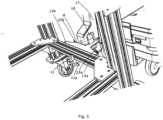
- Figure 1shows a gripping system 1 for an AGV.
- the gripping system 1comprises a base 2, an arm 6 and an end effector 8 with sensors 23, 22a, 22b.
- the base 2comprises means, for example bolt holes, for attaching the base 2 to the AGV, an electrical interface (not shown) for connecting the gripping system to the AGV for the AGV to be able to control the gripping system.
- the base 2may comprise a section 5, for example a recess or an opening, for interaction with the gripping system arm's 6 securing means 9 for securing the arm 6 in a fixed position when such position is needed.
- the base 2further comprises means 7 for attaching the arm 6 to the base 2, for example a vertical shaft.
- the arm's attachment means 7is configured to receive the arm 6 for it to be able to at least partly swivel around the vertical axis of the attachment point i.e. yaw relatively to the body 4 of the AGV.
- the arm 6comprises securing means 9 for locking the arm 6 in a sideways stationary and stable position with respect to the body 4 of the AGV.
- the locking means 9may be any electrically controllable mechanism.
- the securing means 9preferably comprises a locking actuator 9a and a pin 9b which, when actuated protrudes from the frame 16 of the arm 6 towards the base 2 of the gripping system and into an opening 5 in the base 2 and/or in the frame of the AGV.
- the actuator 9ais preferably secured at a first end to the upper frame element 16a and at a second end to the lower frame element 16b, and is preferably situated between lifting bars 18a, 18b.
- the end effector 8is connected to the sliding element 17 via a pivoting connection 10 for a substantially free pivoting motion at a pivoting connection 10.
- the vertical position of the end effector 8, relatively to the sliding bar 16cis adjusted by sliding the sliding element 17 on the sliding bar 16c.
- the end effector 8further comprises a hook 11 for gripping a part of a cart frame and is attached to one end of an elongated element 11.1.
- the elongated element 11.1is movable linearly by actuation means 12, such as a linear actuator, so that part of the cart frame when hooked is secured between the hook 11 and front face 21 of the end effector 8.
- Each of the side sensors 22a, 22bare activated by a respective sensor arm 20a, 20b pivotally attached under the frame 15 of the end effector 8 and positioned between a respective bracket 13a, 13b and a centerline of linear motion of the hook 11.
- First end 20a.1, 20b.1 of each sensor arm 20a, 20bis protruding from the front face 21 of the end effector 8 so that when the end effector 8 starts gripping a connecting part of the cart each sensor arm 20a, 20b is pressed downwards by the connecting part of the cart when the end effector 8 is lifted upwards against the connecting part of the cart.
- the AGV and/or the cartWhile being in the operational mode with a cart attached, the AGV and/or the cart may drive on an uneven surface and roll relatively to each other. Had the connection between the frame of the cart and the gripping system been stiff in all directions, there would have been a risk of twisting between the hook/brackets and the connecting part of the cart and thereby a risk of losing the cart and/or damaging the hook/brackets and/or the connecting part of the cart.
- the constructionensures that the substantially same pulling forces can be transferred at different heights of the gripping portion, so that different type of cart can be pulled. Further the risk of tipping of the AGV is minimized.
- the AGV for towing or pushing a wheeled cart using the gripping system 1comprises drive wheels, a robot body 4 mounted on said drive wheels, a control system utilizing a navigational system.
- the AGVfurther comprises proximity sensors 4.1, 4.2 mounted on the robot body 4 for 270 degrees observation around the robot body 4.
- One proximity sensor 4.1is positioned at the back of the robot body 4, in a corner.
- the other proximity sensor 4.2is positioned in the front of the robot body 4 in a corner.
- the back partis where the cart is attached, and the front part is on the opposite side of the robot body 4.
- the control systemis coupled to the proximity sensors 4.1, 4.2 for adjusting the calculated robotic position and for detecting any obstacles.
Landscapes
- Engineering & Computer Science (AREA)
- Robotics (AREA)
- Mechanical Engineering (AREA)
- Human Computer Interaction (AREA)
- Health & Medical Sciences (AREA)
- General Health & Medical Sciences (AREA)
- Orthopedic Medicine & Surgery (AREA)
- Manipulator (AREA)
Description
- The present invention relates to a gripping system for an autonomous guided vehicle for docking and undocking with a cart and for pulling and pushing the cart. More specifically the invention relates to a manipulator type gripping system.
- Transportation of articles within a structure or between multiple structures has posed, to some degree, a problem. For example, hospitals with over 500 beds, need to use a considerable number of working hours on physical movement of linen, medical specimens, pharmaceuticals, blood products, patient charts, x-rays, and meals.
- Many transportation options exist today as commercially available products, for example, conveyor belts, pneumatic tubes, gimbled carts, and mobile robots. Mobile robots and in particular Autonomous Guided Vehicles (AGV) have been equipped with a drive system under computer control, which allows autonomous guidance between multiple locations. Towing of carts with a rear mounted towing apparatus on AGV's are well known in the art. Commonly a commercial hitch and ball are mounted at one end of the AGV, usually the rear, whereat a cart comprising a releasable socket and a tow bar is connected.
US patent application No. 15/566,516 (publication numberUS2018/0281178 ) discloses a mobile robot system comprising an AGV and a gripping device mounted on the AGV. The AGV comprises a wheel-driving motor, an on-board computer, means for navigation, orientation and maneuvering in an environment with moving obstacles, a sensor system, and a wireless communication system for receiving and sending signals. The gripping system comprises a base for attaching the gripping system to the AGV, an arm and a gripper for gripping a cart. Main challenge for such gripping system is that position of the cart pulling AGV relative to the cart must be very precise in order to be able to grip the cart. This may require several attempts of docking and re-docking, and/or it is required that the docking be done at a slow speed. Another challenge of the prior art is that there is no safe indication of whether the gripper is in a correct alignment with to the connecting part of the cart before and/or while the gripping mechanism is activated. This can lead to an incorrect/weak coupling between the gripping device and the cart, and may lead to necessity of additional coupling attempts, increased wear and tear of the coupling mechanism, and to a situation where the cart is lost during transport.- A further challenge with the prior art solutions is that there is no safe indication of whether a cart is correctly decoupled from the cart-pulling vehicle. This can lead to situations where a cart is accidently still attached to the cart-pulling vehicle while the vehicle is in a "no-cart" driving mode and does not consider the extra foot print of the accidently attached cart while navigating around obstacles and structural elements.
- It is the object of the present invention to improve upon the prior art and provide vehicle gripping system for an AGV with a safe, reliable and quick gripping mechanism and an AGV with such a system. A further object of the invention is to improve the possibility to grip a variety of carts, which may or may-not be specifically designed for automatic transport, in a smooth manner for a safe pulling or pushing operation. A further object is to provide a safer operation of the AGV with the gripper system when no cart is supposed to be attached.
US 2019/0033837 describes a robot that is adapted to pick up and transport objects and comprises a base plate, a drive unit, a pick up unit and a shelf unit, wherein the drive unit, the pick up unit and the shelf unit are positioned on the base plate.US 6,113,343 describes a robot adapted for use in hazardous environments, and particularly adapted for explosives disposal. The robot includes a wheeled platform carrying a winder mechanism which ensures that the remote control cable will not be fouled by the robot or its attachments. Coaxial with the winder mechanism is a turret mechanism that can rotate indefinitely and which carries thereon a manipulator arm section which, includes a first arm pivotable through about 110 DEG and which carries thereon a second arm which is pivotable through about 120 DEG and carries a bulkhead to which any of a plurality of end effectors can be connected by way of a quick connect and disconnect mechanism. The end effectors include a set of links having different lengths, one or two extension links, a wrist and gripper mechanism, an aiming and disruptor mechanism, and a relocatable surveillance camera.- According to
claim 1, agripping system 1 for an autonomous guided vehicle (AGV) is disclosed. Thegripping system 1 comprises abase 2 for attaching thegripping system 1 to abody 4 of the AGV, anarm 6 for manipulating anend effector 8 for gripping a cart for towing or pushing by the AGV. Thearm 6 at one end is pivotally attached to thebase 2, allowing a yaw motion of thearm 6 relatively to the AGV. At the other end, thearm 6 is provided with anend effector 8 being attached to thearm 6. Height of theend effector 8 is adjusted by theactuator 14 of thearm 6. - The
end effector 8 is attached to thearm 6 via apivoting connection 10 that provides a substantially free pivoting motion for allowing a roll motion, while limiting a yaw motion, of theend effector 8 relatively to thearm 6 as the cart and the AGV drive on an uneven surface. Twosensor arms end effector 8 may be adapted to cause theend effector 8 to pivot around itspivoting connection 10 if only one of thesensors arms sensor arms sensors end effector 8 may be provided with ahook 11 and a plurality ofbrackets hook 11 in the direction of thebrackets sensor activating element 11a may be attached to thehook 11 for activating afurther sensor 23 attached to afront face 21. When thesensor 23 is activated, it sends a signal to the control system of the gripping device, indicating a fully contractedhook 11. - According to
claim 11 an autonomous guided vehicle comprising thegripping system 1 is disclosed. The autonomous guided vehicle may comprise drive wheels, arobot body 4 mounted on said drive wheels, a control system utilizing a navigational system, and agripping system 1 mounted on saidrobot body 4 for coupling the cart to said vehicle. The AGV may further comprise at least one proximity sensor 4.1, 4.2 mounted on therobot body 4. The control system may be coupled to said at least one proximity sensor 4.1, 4.2 for adjusting calculated robotic position and detecting any obstacles. - Features of the invention believed to be novel and inventive are set forth with particularity in the appended claims. The invention itself, however, may be best understood by reference to the following detailed description of the invention, which describes exemplary embodiments, given in non-restrictive examples of the invention, taken in conjunction with the accompanying drawings, in which:
Figure 1 shows the gripping system according to the invention mounted on an AGV.Figure 2 shows the end effector of the gripping system according to the invention.Figure 3 shows the end effector of the gripping system according to the invention gripping an element of a cart frame.- Preferred embodiments of the invention will be described herein below with reference to the drawings. Each figure contains the same numbering for the same or equivalent element.
- Numerous specific details are presented in order to provide a complete and comprehensible description of the invention embodiment. However, the person skilled in art will understand that the embodiment examples do not limit the application of the invention which can be implemented without these specific instructions. Well-known methods, procedures and components have not been described in detail for the embodiment in order to avoid any misleading. Furthermore, this description should not be constraining the invention to the given embodiment examples but only be considered as one of possible implementations of the invention.
Figure 1 shows agripping system 1 for an AGV. Thegripping system 1 comprises abase 2, anarm 6 and anend effector 8 withsensors - The
base 2 comprises means, for example bolt holes, for attaching thebase 2 to the AGV, an electrical interface (not shown) for connecting the gripping system to the AGV for the AGV to be able to control the gripping system. Thebase 2 may comprise asection 5, for example a recess or an opening, for interaction with the gripping system arm's 6 securing means 9 for securing thearm 6 in a fixed position when such position is needed. Thebase 2 further comprises means 7 for attaching thearm 6 to thebase 2, for example a vertical shaft. The arm's attachment means 7 is configured to receive thearm 6 for it to be able to at least partly swivel around the vertical axis of the attachment point i.e. yaw relatively to thebody 4 of the AGV. - The
arm 6 further comprises aframe 16. Theframe 16 at one end is attached to themeans 7 for attaching thearm 6 to thebase 2. Opposite end of theframe 16 has anend effector 8 attached thereto. Theframe 16 may comprise anupper frame element 16a andlower frame element 16b. Theupper frame element 16a and/or thelower frame element 16b at one end are attached to themeans 7 for attaching thearm 6 to thebase 2 and at the opposing end are attached to a slidingbar 16c. Theframe 16 is preferably rigid. Thearm 6 further comprises anactuator 14 adapted to adjust the angle of a liftingbar element 17 as well as the height of theend effector 8. Thearm actuator 14 at one end is fixed to thelower frame element 16b and at another end is fixed to the liftingbar 18a or a set of liftingbars respective support bars attachment points 19c. Each of the support bars 19a, 19b at a second end pivotally attached to thelower frame element 16b atattachment points 19d. The lifting bars 18a, 18b are at a respective second end pivotally attached to the slidingelement 17. The slidingelement 17 is sliding up and down the slidingbar 16c when thearm 6actuator 14 acts upon the lifting bars 18a, 18b. The slidingelement 17 is connected to theend effector 8 via apivoting connection 10. The pivotingconnection 10 allows theend effector 8 to partly roll relatively to thebase 2 and thebody 4 of the AGV. - The
arm 6 comprises securing means 9 for locking thearm 6 in a sideways stationary and stable position with respect to thebody 4 of the AGV. The locking means 9 may be any electrically controllable mechanism. The securing means 9 preferably comprises a lockingactuator 9a and a pin 9b which, when actuated protrudes from theframe 16 of thearm 6 towards thebase 2 of the gripping system and into anopening 5 in thebase 2 and/or in the frame of the AGV. Theactuator 9a is preferably secured at a first end to theupper frame element 16a and at a second end to thelower frame element 16b, and is preferably situated between liftingbars actuator 9a is secured to thelower frame element 16b via a pin 9b by inserting the pin 9b into an opening 3 in thelower frame element 16b. While thearm 6 is not locked by the locking means the pin 9b remains inserted into the opening 3 in a retracted position. During locking of thearm 6, theactuator 9a extends the pin 9b through the opening 3 and further into theopening 5 in thebase 2 and/or in the frame of the AGV. When locked, thearm 6 is in parallel to the centerline of thebody 4 of the AGV. During unlocking of thearm 6, theactuator 9a retracts the pin 9b from theopening 5 in thebase 2 and/or in the frame of the AGV. - The
arm 6 may further comprise protectingshields 30 on both sides of thearm 6. - The
end effector 8 is connected to the slidingelement 17 via apivoting connection 10 for a substantially free pivoting motion at apivoting connection 10. The vertical position of theend effector 8, relatively to the slidingbar 16c is adjusted by sliding the slidingelement 17 on the slidingbar 16c. Theend effector 8 further comprises ahook 11 for gripping a part of a cart frame and is attached to one end of an elongated element 11.1. The elongated element 11.1 is movable linearly by actuation means 12, such as a linear actuator, so that part of the cart frame when hooked is secured between thehook 11 andfront face 21 of theend effector 8. The actuation means 12 of thehook 11 preferably comprises a driving part 12.1 and a guiding part 12.2 for accommodating, moving and guiding the elongated element 11.1 for moving thehook 11. The guiding part 12.2 is preferably disposed inside bottom part of aframe 15 of theend effector 8. The driving part 12.1, such as a motor for driving the actuator is preferably positioned near the slidingmember 17 and upwards relatively from the guiding part 12.2. Thehook 11 further comprises asensor activating element 11a. Thesensor activating element 11a activates asensor 23 positioned essentially on thefront face 21 of theend effector 8, approximately opposite thehook 11. Thesensor 11a is activated whenever thehook 11 is moved into a completely closed position by the hook actuation means 12. This ensure that the control system of AGV receives information that thehook 11 has moved into a completely closed position when there is no cart or other element accidentally attached to thehook 11. Accordingly, the AGV can safely switch to a no-cart operation mode. Two supportingbrackets front face 21, right and left of thehook 11, respectively. Together with thehook 11, the supportingbrackets end effector 8 is further provided withside sensors frame 15 of theend effector 8. Theside sensors side sensors respective bracket hook 11. Each of theside sensors respective sensor arm frame 15 of theend effector 8 and positioned between arespective bracket hook 11. First end 20a.1, 20b.1 of eachsensor arm front face 21 of theend effector 8 so that when theend effector 8 starts gripping a connecting part of the cart eachsensor arm end effector 8 is lifted upwards against the connecting part of the cart. Pivoting motion of eachsensor arm respective sensor arm respective pressure sensor end effector 8 is entirely disengaged from the connecting part of the cart the activatingelements end effector sensors sensors end effector 8 is disengaged from the cart frame. - During engagement of the
end effector 8 and the cart frame, theend effector 8 is lifted against the cart connecting part of the cart. If the plane of thebrackets sensor arms end effector 8 to pivot around its pivot point at thepivoting connection 10 and thereby to align with the plane of the connecting part of the frame of the cart until bothsensor arms side sensors side sensors end effector 8 when bothside sensors - While the
end effector 8 and the connecting part of the frame of the cart are aligned, the control-system sends a signal to thehook 11 actuation means 12 to move thehook 11 into a closing position and thereby pressing the connecting part of the cart against thebrackets - While being in the operational mode with a cart attached, the AGV and/or the cart may drive on an uneven surface and roll relatively to each other. Had the connection between the frame of the cart and the gripping system been stiff in all directions, there would have been a risk of twisting between the hook/brackets and the connecting part of the cart and thereby a risk of losing the cart and/or damaging the hook/brackets and/or the connecting part of the cart.
- On the other hand, had the connection between the gripping system and the frame of the cart been flexible in all directions (e.g. a ball coupling), the ability of precise steering of the cart had been lost.
- With the
end effector 8 being pivotally connected to the slidingelement 17 at thepivoting connection 10, the cart and thebody 4 of the AGV can partly roll relatively to each other without the mechanical connection between them being twisted or stressed. - When the cart is attached to the
gripping system 1 thearm 6 is preferably in its center position relative to the AGV. The control system of the AGV identifies the cart by help of a camera/sensor and has stored information about of height and position of the connecting part/ frame of the identified cart. The control system adjusts the height of theend effector 8 so that thehook 11 is at a height, which is low enough to let thehook 11 pass under the cart frame/attachment part. The AGV drives itself to a position in front of the cart so that theend effector 8 is close to the frame/attachment part. Thehook 11 is driven outwards. Theend effector 8 is lifted and thehook 11 is driven inwards until it together with thebrackets - The construction ensures that the substantially same pulling forces can be transferred at different heights of the gripping portion, so that different type of cart can be pulled. Further the risk of tipping of the AGV is minimized.
- Another aspect of the invention is to provide an AGV with the
gripping system 1 as disclosed above. The AGV for towing or pushing a wheeled cart using thegripping system 1 according to the first aspect of the invention comprises drive wheels, arobot body 4 mounted on said drive wheels, a control system utilizing a navigational system. The AGV further comprises proximity sensors 4.1, 4.2 mounted on therobot body 4 for 270 degrees observation around therobot body 4. One proximity sensor 4.1 is positioned at the back of therobot body 4, in a corner. The other proximity sensor 4.2 is positioned in the front of therobot body 4 in a corner. The back part is where the cart is attached, and the front part is on the opposite side of therobot body 4. The control system is coupled to the proximity sensors 4.1, 4.2 for adjusting the calculated robotic position and for detecting any obstacles. - In a particularly preferred embodiment of the present invention, the navigational system includes an automatic control and guide system for reaching a given target and at the same time avoid collision with the surroundings.
- Through the disclosure AGV stands for Autonomous Guided Vehicle.
- Although numerous characteristics and advantages together with structural details and features have been listed in the present description of the invention, the description is provided as an example fulfilment of the invention. Without departing from the scope of the invention as defined by the appended claims, there may be changes in the details, especially in the form, size and layout, in accordance with most widely understood meanings of the concepts and definitions used in claims.
Claims (12)
- Gripping system (1) for an autonomous guided vehicle, i.e., "AGV," wherein the gripping system (1) comprises a base (2) for attaching the gripping system (1) to the AGV, an arm (6) for manipulating an end effector (8) and the end effector (8) for gripping a cart for towing or pushing by the AGV, where the arm (6) at one end is pivotally attached to the base (2) for yaw motion of the arm (6) relatively to the AGV, and at another end is provided with the end effector (8) attached to the arm (6), and comprises an arm actuator (14) adapted to adjust height of the end effector (8),
characterized in that the end effector (8) is attached to the arm (6) via a pivoting connection (10) that provides a substantially free pivoting motion for allowing a roll motion, while limiting a yaw motion, of the end effector (8) relatively to the arm (6) as the cart and the AGV drive on an uneven surface. - The gripping system according to claim 1characterized in that the end effector (8) comprises two sensor arms (20a, 20b) adapted to cause the end effector (8) to pivot around its pivoting connection (10) as long as only one of the sensors arms (20a, 20b) is pressed against the connecting part of the frame of the cart and where the sensor arms (20a, 20b) are arranged to activate first sensors (22a, 22b) for indicating that the end effector (8) is in a correct position in order to apply a clamp force against the connecting part of the frame of the cart.
- The gripping system according to claim 2,characterized in that each sensor arm (20a, 20b) for activating the first sensors (22a, 22b) has a first end (20a.1, 20b.1) protruding from a front face (21) of the end effector (8) for interaction with a cart's frame and a second end (20a.2, 20b.2) for interacting with the respective first sensor (22a, 22b).
- The gripping system according to claim 1 to 2,characterized in that end effector (8) comprises a hook (11) and a plurality of brackets (13a, 13b) adapted for applying a clamping force on the connecting part of the frame of the cart by moving the hook (11) in direction of the brackets (13a, 13b) and a front face (21) of the end effector (8) using hook actuation means (12).
- The gripping system according to claim 4,characterized in that the end effector (8) comprises:a second sensor (23) configured to sense a fully contracted hook (11) and attached to the front face (21) of a frame (15) of the end effector (8); andan activating element (11a) of the second sensor (23) attached to the hook (11) and configured to activate the second sensor (23).
- The gripping system according to any previous claim,characterized in that the arm (6) comprises securing means (9) for restricting sideways motion of the arm (6), and the base (2) comprises a section (5) for interaction with the securing means (9) for securing the arm (6) relatively to the base (2).
- The gripping system according to claim 6,characterized in that the section (5) for interaction with the securing means (9) for securing the arm (6) relatively to the base (2) is a recess or an opening and the securing means (9) comprises a locking actuator (9a) and a pin (9b) for interaction with the recess or an opening (5).
- The gripping system according to any previous claim,characterized in that the arm (6) comprises a rigid frame (16) comprising an upper frame element (16a), a lower frame element (16b) and sliding bar (16c), connecting the upper and lower frame elements (16a, 16b) and being a guiding element for height adjustment of the end effector (8) by sliding element (17) with the end effector (8) attached thereto.
- The gripping system according to claim 8,characterized in that the arm (6) further comprises a set of lifting bars (18a, 18b) and support bars (19a, 19b) where the lifting bars (18a, 18b) at one end of each bar (18a, 18b) are pivotally attached to first end of respective support bars (19a, 19b) and each of the support bars (19a, 19b) at second end of each support bar are pivotally attached to the lower frame element (16b) and the lifting bars (18a, 18b) at their second ends are pivotally attached to the sliding element (17).
- The gripping system according to claim 8,characterized in that the actuator (14) of the arm (6) at one end is fixed to the lower frame element (16b) and at another end is fixed to a set of lifting bars (18a, 18b).
- An autonomous guided vehicle comprising the gripping system (1) according to any of the previous claims.
- A system comprising:the autonomous guided vehicle of claim 11; andthe cart.
Priority Applications (4)
| Application Number | Priority Date | Filing Date | Title |
|---|---|---|---|
| EP20178999.7AEP3922417B1 (en) | 2020-06-09 | 2020-06-09 | Gripping system for an autonomous guided vehicle |
| PCT/EP2021/064668WO2021249827A1 (en) | 2020-06-09 | 2021-06-01 | Gripping system for an autonomous guided vehicle |
| CN202180041000.4ACN115697639A (en) | 2020-06-09 | 2021-06-01 | Gripping systems for automated guided vehicles |
| US17/927,213US12403591B2 (en) | 2020-06-09 | 2021-06-01 | Gripping system for an autonomous guided vehicle |
Applications Claiming Priority (1)
| Application Number | Priority Date | Filing Date | Title |
|---|---|---|---|
| EP20178999.7AEP3922417B1 (en) | 2020-06-09 | 2020-06-09 | Gripping system for an autonomous guided vehicle |
Publications (3)
| Publication Number | Publication Date |
|---|---|
| EP3922417A1 EP3922417A1 (en) | 2021-12-15 |
| EP3922417B1true EP3922417B1 (en) | 2023-06-07 |
| EP3922417C0 EP3922417C0 (en) | 2023-06-07 |
Family
ID=71083388
Family Applications (1)
| Application Number | Title | Priority Date | Filing Date |
|---|---|---|---|
| EP20178999.7AActiveEP3922417B1 (en) | 2020-06-09 | 2020-06-09 | Gripping system for an autonomous guided vehicle |
Country Status (4)
| Country | Link |
|---|---|
| US (1) | US12403591B2 (en) |
| EP (1) | EP3922417B1 (en) |
| CN (1) | CN115697639A (en) |
| WO (1) | WO2021249827A1 (en) |
Families Citing this family (2)
| Publication number | Priority date | Publication date | Assignee | Title |
|---|---|---|---|---|
| EP3922417B1 (en)* | 2020-06-09 | 2023-06-07 | Mobile Industrial Robots A/S | Gripping system for an autonomous guided vehicle |
| CN118322215B (en)* | 2024-05-20 | 2024-12-06 | 薛有红 | A robot vision automated grasping system |
Family Cites Families (61)
| Publication number | Priority date | Publication date | Assignee | Title |
|---|---|---|---|---|
| US4305601A (en) | 1980-03-17 | 1981-12-15 | Kermit Berge | Shopping cart for the handicapped |
| US5518260A (en) | 1994-12-12 | 1996-05-21 | Chrysler Corporation | Disabled vehicle mover |
| US6113343A (en)* | 1996-12-16 | 2000-09-05 | Goldenberg; Andrew | Explosives disposal robot |
| US6244366B1 (en)* | 1997-08-07 | 2001-06-12 | Smarte Carte, Inc. | Cart transporter |
| NL1007225C2 (en) | 1997-10-08 | 1999-04-09 | Maasland Nv | Vehicle combination. |
| US6435803B1 (en) | 1998-07-02 | 2002-08-20 | Coy J. Robinson | Shopping cart collection vehicle and method |
| SE0004465D0 (en) | 2000-12-04 | 2000-12-04 | Abb Ab | Robot system |
| WO2003034970A1 (en)* | 2001-10-26 | 2003-05-01 | Daniel Johnson | Hospital bed power-assist |
| US7134515B2 (en)* | 2002-01-07 | 2006-11-14 | Lenkman Thomas E | Utility transport system |
| US7503510B2 (en) | 2002-10-30 | 2009-03-17 | Deere & Company | Sprayer docking station and monitoring system |
| AU2004236214A1 (en) | 2003-05-03 | 2004-11-18 | Dane Industries | Cart mover |
| US6880652B2 (en)* | 2003-06-09 | 2005-04-19 | Dane Industries, Inc. | Cart pulling vehicle with dual cable drums and dual torsion springs |
| US7571914B2 (en) | 2003-10-15 | 2009-08-11 | Dane Industries, Inc. | Push-pull cart collection device and conversion assembly |
| DE102004040065A1 (en)* | 2004-08-18 | 2006-02-23 | Jungheinrich Aktiengesellschaft | Industrial truck with pallet gripper |
| US7395886B2 (en) | 2004-08-31 | 2008-07-08 | Gatekeeper Systems (Hk) Limited | Dual row cart collector and method |
| WO2006089071A2 (en) | 2005-02-17 | 2006-08-24 | Dane Industries, Inc. | Push-pull cart collection device and conversion assembly |
| JP2006298087A (en)* | 2005-04-19 | 2006-11-02 | Yamaha Motor Co Ltd | Traction device for vehicle |
| US7857342B2 (en)* | 2005-06-07 | 2010-12-28 | Dane Technologies, Inc. | Hitch assembly |
| US7996109B2 (en) | 2005-10-14 | 2011-08-09 | Aethon, Inc. | Robotic ordering and delivery apparatuses, systems and methods |
| DE102006014338B4 (en) | 2006-03-28 | 2019-08-22 | Linde Material Handling Gmbh | Tractor for transporting mobile transport containers |
| AT503295B1 (en) | 2006-06-16 | 2007-09-15 | Scharmueller Josef Ing | Lifting coupler has mounting support, which has locking device for locking carriage element in maximum pivoting condition of pivoted support, and carriage element is lockable in two different positions by locking device |
| US8413752B2 (en) | 2006-10-06 | 2013-04-09 | Irobot Corporation | Robotic vehicle |
| US7878277B2 (en) | 2007-03-23 | 2011-02-01 | Assembled Products Corporation | Motorized wheeled vehicle caddy |
| JP4280940B2 (en) | 2007-09-06 | 2009-06-17 | トヨタ自動車株式会社 | Automatic transfer device |
| US7898470B2 (en) | 2008-03-25 | 2011-03-01 | Trimble Navigation Limited | Method and system for monitoring the positions of multiple towed vehicles using a single high accuracy receiver |
| US8360459B2 (en) | 2008-04-11 | 2013-01-29 | Dane Technologies, Inc. | Cart transporting apparatus |
| US8684373B2 (en)* | 2008-09-23 | 2014-04-01 | Dane Technologies, Inc. | Cart moving machine |
| CN101795141B (en) | 2010-02-22 | 2013-11-27 | 北京航空航天大学 | Applied to the distribution method of the third-order intermodulation distortion parameters in the circuit of the radio frequency system of the receiver |
| US8864164B2 (en) | 2010-12-06 | 2014-10-21 | Seegrid Corporation | Tugger attachment |
| US9004846B2 (en)* | 2011-02-11 | 2015-04-14 | The Procter & Gamble Company | Gripper assembly for moving device |
| EP2728363B1 (en)* | 2011-06-28 | 2021-06-02 | Kabushiki Kaisha Yaskawa Denki | Robot hand and robot |
| US9288938B2 (en) | 2012-06-01 | 2016-03-22 | Rowbot Systems Llc | Robotic platform and method for performing multiple functions in agricultural systems |
| US10807805B2 (en) | 2013-05-17 | 2020-10-20 | Intelligrated Headquarters, Llc | Robotic carton unloader |
| US9650215B2 (en) | 2013-05-17 | 2017-05-16 | Intelligrated Headquarters Llc | Robotic carton unloader |
| SG2013071808A (en) | 2013-09-24 | 2015-04-29 | Ctrlworks Pte Ltd | Offboard navigation apparatus capable of being coupled to a movable platform |
| CN203844860U (en) | 2014-05-04 | 2014-09-24 | 中山明杰自动化科技有限公司 | A self-navigating logistics tractor |
| DK178498B1 (en) | 2015-04-13 | 2016-04-18 | Mobile Ind Robots Aps | ROBOT-BASED VEHICLE TO TOUGH A CAR |
| US9656394B2 (en)* | 2015-05-21 | 2017-05-23 | GM Global Technology Operations LLC | Robotic system with reconfigurable end-effector assembly |
| US9669857B1 (en) | 2015-07-01 | 2017-06-06 | Randall D Rainey | Propulsion device for hand-pushed equipment |
| US10233056B1 (en)* | 2015-08-05 | 2019-03-19 | Jeffery L. Brauer | Grasping apparatus and methods for transporting rolling racks |
| EP3192616B1 (en)* | 2016-01-14 | 2024-09-25 | Jungheinrich AG | Robot to pick up and transport objects and method using such a robot |
| CA2961938A1 (en) | 2016-04-01 | 2017-10-01 | Wal-Mart Stores, Inc. | Systems and methods for moving pallets via unmanned motorized unit-guided forklifts |
| US10960717B2 (en)* | 2016-05-12 | 2021-03-30 | Aichikikai Technosystem Co., Ltd. | Towing device of automatic guided vehicle and automatic guided vehicle having the same |
| EP3541219B1 (en)* | 2016-11-16 | 2024-01-24 | Wink Robotics | Eyelid covering and stabilization for automatic eyelash extension |
| CN107032141B (en)* | 2017-05-26 | 2020-06-26 | 华中科技大学 | A mobile robot for automatic loading and unloading of goods |
| US11008033B2 (en)* | 2018-01-26 | 2021-05-18 | Toyota Research Institute, Inc. | Hitch-mounted robot systems |
| US11331796B2 (en)* | 2018-02-12 | 2022-05-17 | Brain Corporation | Autonomous multi-tasking modular robotic system |
| US10751888B2 (en)* | 2018-10-04 | 2020-08-25 | Advanced Intelligent Systems Inc. | Manipulator apparatus for operating on articles |
| US10645882B1 (en)* | 2018-10-29 | 2020-05-12 | Advanced Intelligent Systems Inc. | Method and apparatus for performing pruning operations using an autonomous vehicle |
| US10966374B2 (en)* | 2018-10-29 | 2021-04-06 | Advanced Intelligent Systems Inc. | Method and apparatus for performing pruning operations using an autonomous vehicle |
| US12415268B2 (en)* | 2019-01-03 | 2025-09-16 | Lucomm Technologies, Inc. | Robotic cart |
| CN110666815A (en)* | 2019-11-05 | 2020-01-10 | 新疆大学 | A snow sweeping robot based on a compressed snow block collecting device |
| EP3922417B1 (en)* | 2020-06-09 | 2023-06-07 | Mobile Industrial Robots A/S | Gripping system for an autonomous guided vehicle |
| EP3960691B1 (en)* | 2020-09-01 | 2023-12-27 | Tractonomy Robotics BV | Autonomous mobile robot system for improved docking with a wheeled cart |
| EP3971001B1 (en)* | 2020-09-16 | 2024-01-31 | Tata Consultancy Services Limited | Automated carrier tugger mounted on an autonomous mobile robot for tugging a carrier |
| CN112295134B (en)* | 2020-10-13 | 2021-08-24 | 三峡大学 | A kind of narrow space rescue equipment and using method |
| EP4433326A4 (en)* | 2021-11-15 | 2025-04-02 | ST Engineering Aethon, Inc. | ADAPTIVE MOBILE ROBOT BEHAVIOR BASED ON PAYLOAD |
| WO2023115068A1 (en)* | 2021-12-17 | 2023-06-22 | Hall Labs, Llc | Self-propelled cart |
| CN114800425B (en)* | 2022-04-19 | 2023-06-02 | 南华大学 | Garbage container transfer robot and method |
| US12134286B1 (en)* | 2023-07-30 | 2024-11-05 | James Stephen Adams | Device for quickly attaching and detaching equipment |
| KR102729338B1 (en)* | 2024-05-02 | 2024-11-14 | 주식회사 유에이로보틱스 | Coupling device for mobile robot and battery cart |
- 2020
- 2020-06-09EPEP20178999.7Apatent/EP3922417B1/enactiveActive
- 2021
- 2021-06-01CNCN202180041000.4Apatent/CN115697639A/enactivePending
- 2021-06-01WOPCT/EP2021/064668patent/WO2021249827A1/ennot_activeCeased
- 2021-06-01USUS17/927,213patent/US12403591B2/enactiveActive
Also Published As
| Publication number | Publication date |
|---|---|
| US20230202032A1 (en) | 2023-06-29 |
| CN115697639A (en) | 2023-02-03 |
| WO2021249827A1 (en) | 2021-12-16 |
| EP3922417C0 (en) | 2023-06-07 |
| US12403591B2 (en) | 2025-09-02 |
| EP3922417A1 (en) | 2021-12-15 |
Similar Documents
| Publication | Publication Date | Title |
|---|---|---|
| US10668617B2 (en) | Robotic cart pulling vehicle for automated pulling of carts | |
| CN110340862B (en) | Autonomous mobile transfer robot | |
| CN110340863B (en) | Autonomous Mobile Handling Robot | |
| EP3922417B1 (en) | Gripping system for an autonomous guided vehicle | |
| US6738691B1 (en) | Control handle for intelligent assist devices | |
| US7314103B2 (en) | Re-locatable operator station | |
| US12150721B2 (en) | Controlling a surgical instrument | |
| CN110340868B (en) | Work mechanism and autonomous mobile transfer robot | |
| CN110340861B (en) | Autonomous mobile transfer robot, jig thereof and operation mechanism | |
| KR102568404B1 (en) | Trailer coupling assemblies and vehicles with trailer coupling assemblies | |
| EP4273029A2 (en) | Navigator | |
| CN110712693A (en) | Work platform mover system | |
| JP4958069B2 (en) | Transport robot and 3-DOF parallel link mechanism | |
| CN114191097A (en) | Portal frame convenient to adjust and interventional operation robot system with portal frame | |
| US12110050B2 (en) | Navigator | |
| US20240409142A1 (en) | Navigator | |
| US20240225943A1 (en) | Conveyance Systems for A Maneuverable Walk-About Platform for A Robotic Upper Exoskeleton | |
| US20240227162A1 (en) | Walk-About Exoskeleton | |
| US20250169387A1 (en) | Connection system | |
| US20240225942A1 (en) | Convertible Ride-On and Walk-About Platform for A Robotic Upper Exoskeleton |
Legal Events
| Date | Code | Title | Description |
|---|---|---|---|
| PUAI | Public reference made under article 153(3) epc to a published international application that has entered the european phase | Free format text:ORIGINAL CODE: 0009012 | |
| STAA | Information on the status of an ep patent application or granted ep patent | Free format text:STATUS: THE APPLICATION HAS BEEN PUBLISHED | |
| AK | Designated contracting states | Kind code of ref document:A1 Designated state(s):AL AT BE BG CH CY CZ DE DK EE ES FI FR GB GR HR HU IE IS IT LI LT LU LV MC MK MT NL NO PL PT RO RS SE SI SK SM TR | |
| B565 | Issuance of search results under rule 164(2) epc | Effective date:20201216 | |
| STAA | Information on the status of an ep patent application or granted ep patent | Free format text:STATUS: REQUEST FOR EXAMINATION WAS MADE | |
| 17P | Request for examination filed | Effective date:20220530 | |
| RBV | Designated contracting states (corrected) | Designated state(s):AL AT BE BG CH CY CZ DE DK EE ES FI FR GB GR HR HU IE IS IT LI LT LU LV MC MK MT NL NO PL PT RO RS SE SI SK SM TR | |
| GRAP | Despatch of communication of intention to grant a patent | Free format text:ORIGINAL CODE: EPIDOSNIGR1 | |
| STAA | Information on the status of an ep patent application or granted ep patent | Free format text:STATUS: GRANT OF PATENT IS INTENDED | |
| INTG | Intention to grant announced | Effective date:20230110 | |
| GRAS | Grant fee paid | Free format text:ORIGINAL CODE: EPIDOSNIGR3 | |
| GRAA | (expected) grant | Free format text:ORIGINAL CODE: 0009210 | |
| STAA | Information on the status of an ep patent application or granted ep patent | Free format text:STATUS: THE PATENT HAS BEEN GRANTED | |
| AK | Designated contracting states | Kind code of ref document:B1 Designated state(s):AL AT BE BG CH CY CZ DE DK EE ES FI FR GB GR HR HU IE IS IT LI LT LU LV MC MK MT NL NO PL PT RO RS SE SI SK SM TR | |
| REG | Reference to a national code | Ref country code:GB Ref legal event code:FG4D | |
| REG | Reference to a national code | Ref country code:CH Ref legal event code:EP Ref country code:AT Ref legal event code:REF Ref document number:1573594 Country of ref document:AT Kind code of ref document:T Effective date:20230615 | |
| REG | Reference to a national code | Ref country code:DE Ref legal event code:R096 Ref document number:602020011562 Country of ref document:DE | |
| U01 | Request for unitary effect filed | Effective date:20230623 | |
| U07 | Unitary effect registered | Designated state(s):AT BE BG DE DK EE FI FR IT LT LU LV MT NL PT SE SI Effective date:20230630 | |
| REG | Reference to a national code | Ref country code:LT Ref legal event code:MG9D | |
| PG25 | Lapsed in a contracting state [announced via postgrant information from national office to epo] | Ref country code:NO Free format text:LAPSE BECAUSE OF FAILURE TO SUBMIT A TRANSLATION OF THE DESCRIPTION OR TO PAY THE FEE WITHIN THE PRESCRIBED TIME-LIMIT Effective date:20230907 Ref country code:ES Free format text:LAPSE BECAUSE OF FAILURE TO SUBMIT A TRANSLATION OF THE DESCRIPTION OR TO PAY THE FEE WITHIN THE PRESCRIBED TIME-LIMIT Effective date:20230607 | |
| PG25 | Lapsed in a contracting state [announced via postgrant information from national office to epo] | Ref country code:RS Free format text:LAPSE BECAUSE OF FAILURE TO SUBMIT A TRANSLATION OF THE DESCRIPTION OR TO PAY THE FEE WITHIN THE PRESCRIBED TIME-LIMIT Effective date:20230607 Ref country code:HR Free format text:LAPSE BECAUSE OF FAILURE TO SUBMIT A TRANSLATION OF THE DESCRIPTION OR TO PAY THE FEE WITHIN THE PRESCRIBED TIME-LIMIT Effective date:20230607 Ref country code:GR Free format text:LAPSE BECAUSE OF FAILURE TO SUBMIT A TRANSLATION OF THE DESCRIPTION OR TO PAY THE FEE WITHIN THE PRESCRIBED TIME-LIMIT Effective date:20230908 | |
| PG25 | Lapsed in a contracting state [announced via postgrant information from national office to epo] | Ref country code:SK Free format text:LAPSE BECAUSE OF FAILURE TO SUBMIT A TRANSLATION OF THE DESCRIPTION OR TO PAY THE FEE WITHIN THE PRESCRIBED TIME-LIMIT Effective date:20230607 | |
| PG25 | Lapsed in a contracting state [announced via postgrant information from national office to epo] | Ref country code:IS Free format text:LAPSE BECAUSE OF FAILURE TO SUBMIT A TRANSLATION OF THE DESCRIPTION OR TO PAY THE FEE WITHIN THE PRESCRIBED TIME-LIMIT Effective date:20231007 | |
| U21 | Renewal fee for the european patent with unitary effect paid with additional fee | Year of fee payment:4 Effective date:20231219 | |
| PG25 | Lapsed in a contracting state [announced via postgrant information from national office to epo] | Ref country code:SM Free format text:LAPSE BECAUSE OF FAILURE TO SUBMIT A TRANSLATION OF THE DESCRIPTION OR TO PAY THE FEE WITHIN THE PRESCRIBED TIME-LIMIT Effective date:20230607 Ref country code:SK Free format text:LAPSE BECAUSE OF FAILURE TO SUBMIT A TRANSLATION OF THE DESCRIPTION OR TO PAY THE FEE WITHIN THE PRESCRIBED TIME-LIMIT Effective date:20230607 Ref country code:RO Free format text:LAPSE BECAUSE OF FAILURE TO SUBMIT A TRANSLATION OF THE DESCRIPTION OR TO PAY THE FEE WITHIN THE PRESCRIBED TIME-LIMIT Effective date:20230607 Ref country code:IS Free format text:LAPSE BECAUSE OF FAILURE TO SUBMIT A TRANSLATION OF THE DESCRIPTION OR TO PAY THE FEE WITHIN THE PRESCRIBED TIME-LIMIT Effective date:20231007 Ref country code:CZ Free format text:LAPSE BECAUSE OF FAILURE TO SUBMIT A TRANSLATION OF THE DESCRIPTION OR TO PAY THE FEE WITHIN THE PRESCRIBED TIME-LIMIT Effective date:20230607 | |
| REG | Reference to a national code | Ref country code:CH Ref legal event code:PL | |
| PG25 | Lapsed in a contracting state [announced via postgrant information from national office to epo] | Ref country code:PL Free format text:LAPSE BECAUSE OF FAILURE TO SUBMIT A TRANSLATION OF THE DESCRIPTION OR TO PAY THE FEE WITHIN THE PRESCRIBED TIME-LIMIT Effective date:20230607 | |
| REG | Reference to a national code | Ref country code:DE Ref legal event code:R097 Ref document number:602020011562 Country of ref document:DE | |
| PG25 | Lapsed in a contracting state [announced via postgrant information from national office to epo] | Ref country code:MC Free format text:LAPSE BECAUSE OF FAILURE TO SUBMIT A TRANSLATION OF THE DESCRIPTION OR TO PAY THE FEE WITHIN THE PRESCRIBED TIME-LIMIT Effective date:20230607 | |
| REG | Reference to a national code | Ref country code:IE Ref legal event code:MM4A | |
| PG25 | Lapsed in a contracting state [announced via postgrant information from national office to epo] | Ref country code:MC Free format text:LAPSE BECAUSE OF FAILURE TO SUBMIT A TRANSLATION OF THE DESCRIPTION OR TO PAY THE FEE WITHIN THE PRESCRIBED TIME-LIMIT Effective date:20230607 | |
| PLBE | No opposition filed within time limit | Free format text:ORIGINAL CODE: 0009261 | |
| STAA | Information on the status of an ep patent application or granted ep patent | Free format text:STATUS: NO OPPOSITION FILED WITHIN TIME LIMIT | |
| PG25 | Lapsed in a contracting state [announced via postgrant information from national office to epo] | Ref country code:IE Free format text:LAPSE BECAUSE OF NON-PAYMENT OF DUE FEES Effective date:20230609 | |
| PG25 | Lapsed in a contracting state [announced via postgrant information from national office to epo] | Ref country code:IE Free format text:LAPSE BECAUSE OF NON-PAYMENT OF DUE FEES Effective date:20230609 Ref country code:CH Free format text:LAPSE BECAUSE OF NON-PAYMENT OF DUE FEES Effective date:20230630 | |
| 26N | No opposition filed | Effective date:20240308 | |
| U20 | Renewal fee for the european patent with unitary effect paid | Year of fee payment:5 Effective date:20240509 | |
| GBPC | Gb: european patent ceased through non-payment of renewal fee | Effective date:20240609 | |
| PG25 | Lapsed in a contracting state [announced via postgrant information from national office to epo] | Ref country code:GB Free format text:LAPSE BECAUSE OF NON-PAYMENT OF DUE FEES Effective date:20240609 | |
| U20 | Renewal fee for the european patent with unitary effect paid | Year of fee payment:6 Effective date:20250509 | |
| PG25 | Lapsed in a contracting state [announced via postgrant information from national office to epo] | Ref country code:CY Free format text:LAPSE BECAUSE OF FAILURE TO SUBMIT A TRANSLATION OF THE DESCRIPTION OR TO PAY THE FEE WITHIN THE PRESCRIBED TIME-LIMIT; INVALID AB INITIO Effective date:20200609 | |
| PG25 | Lapsed in a contracting state [announced via postgrant information from national office to epo] | Ref country code:HU Free format text:LAPSE BECAUSE OF FAILURE TO SUBMIT A TRANSLATION OF THE DESCRIPTION OR TO PAY THE FEE WITHIN THE PRESCRIBED TIME-LIMIT; INVALID AB INITIO Effective date:20200609 |