EP3922196B1 - Intraoperative clip loading device - Google Patents
Intraoperative clip loading deviceDownload PDFInfo
- Publication number
- EP3922196B1 EP3922196B1EP21164196.4AEP21164196AEP3922196B1EP 3922196 B1EP3922196 B1EP 3922196B1EP 21164196 AEP21164196 AEP 21164196AEP 3922196 B1EP3922196 B1EP 3922196B1
- Authority
- EP
- European Patent Office
- Prior art keywords
- clip
- ligation
- outer tube
- retainers
- loading device
- Prior art date
- Legal status (The legal status is an assumption and is not a legal conclusion. Google has not performed a legal analysis and makes no representation as to the accuracy of the status listed.)
- Active
Links
Images


Classifications
- A—HUMAN NECESSITIES
- A61—MEDICAL OR VETERINARY SCIENCE; HYGIENE
- A61B—DIAGNOSIS; SURGERY; IDENTIFICATION
- A61B17/00—Surgical instruments, devices or methods
- A61B17/12—Surgical instruments, devices or methods for ligaturing or otherwise compressing tubular parts of the body, e.g. blood vessels or umbilical cord
- A61B17/128—Surgical instruments, devices or methods for ligaturing or otherwise compressing tubular parts of the body, e.g. blood vessels or umbilical cord for applying or removing clamps or clips
- A61B17/1285—Surgical instruments, devices or methods for ligaturing or otherwise compressing tubular parts of the body, e.g. blood vessels or umbilical cord for applying or removing clamps or clips for minimally invasive surgery
- A—HUMAN NECESSITIES
- A61—MEDICAL OR VETERINARY SCIENCE; HYGIENE
- A61B—DIAGNOSIS; SURGERY; IDENTIFICATION
- A61B17/00—Surgical instruments, devices or methods
- A61B17/12—Surgical instruments, devices or methods for ligaturing or otherwise compressing tubular parts of the body, e.g. blood vessels or umbilical cord
- A61B17/122—Clamps or clips, e.g. for the umbilical cord
- A61B17/1222—Packages or dispensers therefor
- A—HUMAN NECESSITIES
- A61—MEDICAL OR VETERINARY SCIENCE; HYGIENE
- A61B—DIAGNOSIS; SURGERY; IDENTIFICATION
- A61B17/00—Surgical instruments, devices or methods
- A61B17/12—Surgical instruments, devices or methods for ligaturing or otherwise compressing tubular parts of the body, e.g. blood vessels or umbilical cord
- A61B17/122—Clamps or clips, e.g. for the umbilical cord
- A61B17/1227—Spring clips
- A—HUMAN NECESSITIES
- A61—MEDICAL OR VETERINARY SCIENCE; HYGIENE
- A61B—DIAGNOSIS; SURGERY; IDENTIFICATION
- A61B17/00—Surgical instruments, devices or methods
- A61B2017/00367—Details of actuation of instruments, e.g. relations between pushing buttons, or the like, and activation of the tool, working tip, or the like
- A61B2017/00407—Ratchet means
- A—HUMAN NECESSITIES
- A61—MEDICAL OR VETERINARY SCIENCE; HYGIENE
- A61B—DIAGNOSIS; SURGERY; IDENTIFICATION
- A61B17/00—Surgical instruments, devices or methods
- A61B2017/0042—Surgical instruments, devices or methods with special provisions for gripping
- A—HUMAN NECESSITIES
- A61—MEDICAL OR VETERINARY SCIENCE; HYGIENE
- A61B—DIAGNOSIS; SURGERY; IDENTIFICATION
- A61B17/00—Surgical instruments, devices or methods
- A61B2017/00526—Methods of manufacturing
- A61B2017/0053—Loading magazines or sutures into applying tools
Definitions
- This technologyis generally related to surgical clip appliers and, more particularly, to a clip loading device for intraoperatively loading ligation clips into a ligation clip applier.
- Endoscopic ligation clip appliersare used to apply ligation clips to body vessels during surgical procedures to occlude or partially occlude the body vessels. These clip appliers are inserted through small diameter cannulas or small incisions in a patient's body to access a surgical site within a body cavity. Performing a surgical procedure endoscopically reduces the amount of trauma inflicted on a patient during a surgical procedure to minimize patient discomfort and reduce patient recovery times.
- Surgical clip appliersinclude single-fire clip appliers and multi-fire clip appliers.
- single-fire clip appliersa ligation clip is loaded into the clip applier after each use.
- the clip applieris used to withdraw a single clip from a clip package to load the clip into jaws of the clip applier prior to each use of the clip applier.
- the clip applieris removed from a body cavity after each use to reload a ligation clip into the clip applier. This process is time consuming and increases the possibility of infection, thus increasing trauma to the patient.
- Multi-fire clip appliersinclude a clip cartridge that is coupled to an elongate body of the clip applier that includes a plurality of ligation clips that are sequentially supplied to the jaws of the clip applier to facilitate placement of multiple clips on a body vessel or on body vessels without withdrawing the clip applier from within a body cavity.
- United States Patent Application US 2004/0097971 A1discloses a surgical clip applying apparatus comprising an actuator device, a ratchet mechanism, a locking mechanism, and a clip driving device.
- International Patent Application WO 2017/019865 A1discloses a surgical clip cartridge including a base portion extending in a longitudinal direction, the base portion having a bottom surface and defining a mounting groove for attaching the base portion onto a surgical instrument shaft.
- United States Patent Application US 2014/0309677 A1discloses a clip holder configured to retain one or more clips or staples.
- proximalis used generally to refer to that portion of the device that is closer to a clinician
- distalis used generally to refer to that portion of the device that is farther from the clinician
- endoscopicis used generally to refer to endoscopic, laparoscopic, arthroscopic, and/or any other procedure conducted through a small diameter incision or cannula.
- clinicianis used generally to refer to medical personnel including doctors, nurses, and support personnel.
- the disclosed intraoperative clip loading deviceincludes an elongate body that supports a plurality of ligation clips and a clip advancing member for advancing the plurality of ligation clips towards a distal portion of the elongate body.
- the distal portion of the elongate bodydefines an opening that is accessible to a ligation clip applier to facilitate loading of the ligation clip applier through the distal portion of the elongate body of the intraoperative clip loading device.
- the elongate bodyis dimensioned to be positioned through a standard size port of a cannula to access a surgical site.
- the loading devicecan be positioned within a body cavity during an endoscopic surgical procedure to facilitate intraoperative loading of the ligation clip applier in vivo.
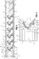
- FIG. 1illustrates exemplary aspects of the disclosed intraoperative clip loading device shown generally as loading device 10.
- the loading device 10includes a handle assembly 12 and an elongate body 14.
- the elongate body 14includes a distal portion 14a and a proximal portion 14b that is fixedly coupled to the handle 12.
- the handle assembly 12includes a handle grip 16 and an actuator 18.
- the handle grip 16is illustrated as a pistol-type grip, it is envisioned that the handle grip 16 may have a variety of configurations that are ergonomically pleasing to a clinician.
- FIG. 2illustrates a ligation clip 20, a plurality of which is received within the elongate body 14 of the loading device 10.
- Each of the ligation clips 20includes a first beam 22, a second beam 24, and a hinge portion 26 that interconnects the first beam 22 to the second beam 24 and allows the ligation clip 20 to pivot between open and clamped positions.
- Each of the beamsincludes bosses 28 that are positioned on opposite sides of the respective beams 22 and 24. The bosses 28, as known in the art, provide engagement surfaces that facilitate securement of the ligation clip 20 onto to a ligation clip applier 100 ( FIG. 8A ).
- FIGS. 3-5Billustrate the elongate body 14 of the loading device 10 which includes an outer tube 30, a clip advancing member 32, clip retainers 34, clip locking arms 36, and a guide member 38.
- the outer tube 30is hollow and houses each of the components of the elongate body 14 listed above as well as a plurality of ligation clips 20.
- the outer tube 30includes a distal portion 30a that receives or supports the guide member 38.
- the outer tube 30 and the guide member 38are integrally formed although it is envisioned that the guide member 38 could be formed separately from the outer tube 30 and secured to the outer tube 30.
- the guide member 38defines a through bore 40 and includes diametrically opposed rectangular guide channels 42 that extend from the outwardly from the through bore 40.
- the guide channels 42receive jaws 112 ( FIG. 8A ) of an end effector 114 of a clip applier 100 to guide the jaws 112 into engagement with a distal-most clip 20a of the plurality of clips 20 supported within the outer tube 30 as described in further detail below.
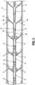
- the clip retainers 34are formed of a resilient material and include a base portion 50 and flexible arms 52.
- the flexible arms 52extend from the base portion and include a transverse portion 52a and a longitudinal portion 52b.
- the base portion 50 of each of the clip retainers 34is secured to an inner wall 44 of the outer tube 30.
- Each of the clip retainers 34is positioned in opposition to another one of the clip retainers 34 to define a clip retention pocket 56 between the two opposed clip retainers 34.
- the clip retention pockets 56are defined between respective opposed clip retainers 34 along the outer tube 30 from a proximal end portion of the outer tube 30 to a distal end portion of the outer tube 30.
- the flexible arms 52 of the clip retainers 34flex outwardly and apply an inwardly directed force onto the hinge portion 26 and beams 22 and 24 of the ligation clip 20 to support the ligation clip 20 within the outer tube 30 of the elongate body 14 of the loading device 10 ( FIG. 5B ).
- Each of the longitudinal portions 52b of the flexible arms 52 of the clip retainers 34includes a flexible tab 58 that has a proximal end that is secured to the flexible arm 52 in cantilevered fashion and a distal end that defines a distal stop surface 60.
- the tabs 58are deformed inwardly to allow the ligation clip 20 to move distally by the tab 58.
- the tab 58springs outwardly such that the stop surface 60 of the tab 58 is aligned with the hinge portion 26 of a respective one of the ligation clips 20 to obstruct proximal movement of the ligation clip 20 within the outer tube 30.
- FIGS. 3 and 4illustrate the clip advancing member 32 which is movable within the outer tube 30 between retracted and advanced positions and includes an elongate member 64 and a plurality of resilient fingers 66.
- Each of the plurality of resilient fingers 66extends from the elongate member 64 in a distal direction at an acute angle into the outer tube 30 and engages the second beam 24 of one of the ligation clips 20.
- the elongate member 64has a proximal portion (not shown) that is coupled to the actuator 18 of the handle assembly 12 such that actuation of the actuator 18 moves the clip advancing member 32 between its retracted and advanced positions.
- each of the ligation clips 20is advanced within the outer tube 30 from a first retention pocket 56 between two opposed clip retainers 34 to the next distally located retention pocket 56 within the outer tube 30.
- the clip locking arms 36are secured in cantilevered fashion within the distal portion of the outer tube 30 and are formed of a resilient material.
- Each of the clip locking arms 36has a proximal portion 70 that is secured to the inner wall 44 of the outer tube 30 and a distal portion 72 that includes a concavity 74.
- the concavities 74 of the clip locking arms 36receive the bosses 28 of a respective ligation clip 20 when the ligation clip 20 is delivered to a position between the clip locking arms 36 by the clip advancing member 32.
- the distal portion 72 of each of the clip locking arms 36is positioned adjacent to a cutout 76 formed in the outer tube 30 of the elongate body 14.
- the cutouts 76accommodate the distal portions of the clip locking arms 36 as a ligation clip 30 is advanced to a position between the clip locking arms 36. More specifically, the cutouts 76 allow the clip locking arms 36 to flex outwardly when a ligation clip 20 is delivered to the clip locking arms 36 by the clip advancing member 32 and when a ligation clip 20 is removed from the elongate body 14 by a clip applier 100 ( FIG. 8A ) as described in further detail below.
- the clip locking arms 36are longitudinally aligned with guide channels 42 formed in the guide member 38 and with the clip retention pockets 56 defined by the clip retainers 34 positioned along the length of the outer tube 30.
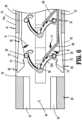
- FIG. 6illustrates the distal portion 14a of the elongate body 14 as the clip advancing member 32 is moved towards its advanced position to advance the plurality of clips 20 within the outer tube 30 of the elongate body 14.
- each of the resilient fingers 66 of the clip advancing member 32engages a respective ligation clip 20 and advances a respective ligation clip 20 from a clip retention pocket 56 to the next distally located clip retention pocket 56 defined between two opposed clip retainers 34.
- the distal-most clip 20a of the plurality of ligation clips 20is advanced to a position between the clip locking arms 36.
- the bosses 28 on the distal-most clip 20aengage the clip locking arms 36 to deflect the distal portions 72 of the clip locking arms 36 in the direction of arrow "B" into the cutouts 76 formed in the outer tube 30.
- the clip locking arms 36snap inwardly to position the bosses 28 within the concavities 74 to grip the ligation clip 20a between the clip locking arms 36.
- the ligation clips 20pass over one of the flexible tabs 58 of the clip retainers 34. As the ligation clips 20 pass over the flexible tabs 58, the flexible tabs 58 are deformed inwardly until the hinge portion 26 of the ligation clips 20 pass distally over the flexible tabs 58. Once the ligation clips 20 pass over the flexible tabs 58, the flexible tabs 58 return to a positon in which the stop surfaces 60 of the tabs 58 are aligned with the hinge portions 26 of the ligation clips 20 to prevent proximal movement of the ligation clips 20 within the outer tube 30.
- FIG. 7illustrates the clip advancing member 32 as the clip advancing member 32 moves in the direction of arrow "C" from its advanced position back towards its retracted position.
- the resilient fingers 66which are angled towards the distal end of the outer tube 30, engage the ligation clips 30 positioned proximally of the respective resilient fingers 66.
- the ligation clips 20are prevented from moving proximally within the outer tube 30 by the flexible tabs 58.
- the resilient fingers 66 of the clip advancing membersare deformed inwardly towards the elongate member 64 in the direction indicated by arrows "D” and pass beneath the respective ligation clips 20.
- the resilient fingers 66return to their undeformed positions shown in FIG. 3 located proximally of the respective ligation clips 20.
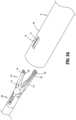
- FIGS. 8-11illustrate the loading device 10 as a ligation clip applier 100 is inserted into the distal portion 14a of the elongate body 14 to remove the distal-most ligation clip 20a ( FIG. 10 ) from the loading device 10.
- the clip applier 100includes an end effector 114 that includes jaws 112.
- the jaws 112are movable in relation to each other to move a ligation clip 20 from an open position to a clamped position as known in the art.
- Each of the jaws 112 of the end effector 114includes a distal portion including a hook portion 118 that defines a recess 120 that receives the bosses 28 of a ligation clip 20 to secure the ligation clip 20 to the clip applier 100.
- the jaws 112 of the clip applier 100are inserted into the channels 42 of the guide member 38 in the distal portion 14a of the loading device 100.
- the channels 42are aligned with the clip retention pockets 56 defined by the clip retainers 34 and with the clip locking arms 36 such that the jaws 112 of the clip applier 100 are aligned with the first and second beams 22 and 24 of the distal-most ligation clip 20a.
- the clip locking arms 36are deflected outwardly in the direction of arrows "E" in FIG.
- the jaws 112 of the clip applier 100move further distally into the outer tube 30 of the loading device 10, the jaws 112 engage the beams 22 and 24 of the ligation clip 20a such that the bosses 28 are received in the recesses 120 of the hook portions 118 of the jaws 112.
- the stop surface 60 of the tab 58 of the clip retainers 34engage the ligation clip 20a to prevent proximal movement of the ligation clip 20a within the outer tube 30.
- the actuator 18 of the handle assembly 12 of the loading device 10can be actuated to advance the ligation clips 20 within the elongate body 14 to position the distal-most clip 20a in position between the clip locking arms 36 of the loading device 10.
- the disclosed loading device 10can be inserted through a cannula (not shown) to a surgical site within a body cavity to facilitate reloading of a single-use clip applier 100 during a surgical procedure at the surgical site.
- the elongate body 14has a length to access the surgical site and to house a plurality of ligation clips 20, e.g., 5 or more ligation clips 20.
- the loading device 10obviates any need to remove a single-use clip applier from a body cavity through a cannula to facilitate reloading of the clip applier 100.
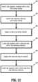
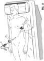
- FIGS. 12-16illustrate use of the loading device 10 and the clip applier 100 during a surgical procedure that requires more than one ligation clip 20 to ligate a body vessel 200.
- the clip applier 100 and the loading device 10are inserted through separate incisions "I" into a patient "P” to access a body cavity "BC" ( FIG. 14 ).
- Steps 300 and 302 in FIG. 12 .It is envisioned that cannulas 202a and 202b can be positioned within the incisions "I” and the clip applier 100 and the loading device 10 can be inserted through the cannulas 202a and 202b.
- the clip applier 100is loaded with a first clip 20a ( FIG.
- the clip applier 100is manipulated to position the jaws 112 of the clip applier 100 about the body vessel 200 ( FIG. 14 ) and the clip applier 100 is actuated to close the ligation clip 20a about the body vessel 200. (Step 304 in FIG. 12 .) After the ligation clip 20a is closed about the body vessel 200, the jaws 112 of the clip applier 100 are removed from about the closed ligation clip 20a and are inserted into the distal end of the loading device 10 ( FIG. 15 ) in the manner described above to retrieve a second ligation clip 20b ( FIG.
- the clip applier 10can be inserted through the cannula 202a without a ligation clip 20 supported between the jaws 112 of the clip applier 10.
- the jaws 112 of the clip applier 100can be inserted into the loading device 10 to retrieve a clip 20a-b prior to placement of the first ligation clip 20a about the body vessel 200. Inserting the clip applier 100 through the cannula 202a without a clip 20a-b loaded between the jaws 112 may allow the clip applier 100 to be inserted through a smaller diameter cannula.
Landscapes
- Health & Medical Sciences (AREA)
- Surgery (AREA)
- Life Sciences & Earth Sciences (AREA)
- Heart & Thoracic Surgery (AREA)
- Nuclear Medicine, Radiotherapy & Molecular Imaging (AREA)
- Vascular Medicine (AREA)
- Engineering & Computer Science (AREA)
- Biomedical Technology (AREA)
- Reproductive Health (AREA)
- Medical Informatics (AREA)
- Molecular Biology (AREA)
- Animal Behavior & Ethology (AREA)
- General Health & Medical Sciences (AREA)
- Public Health (AREA)
- Veterinary Medicine (AREA)
- Surgical Instruments (AREA)
Description
- This application claims the benefit of and priority to
U.S. Provisional Patent Application Serial No. 63/000,091, filed March 26, 2020 - This technology is generally related to surgical clip appliers and, more particularly, to a clip loading device for intraoperatively loading ligation clips into a ligation clip applier.
- Endoscopic ligation clip appliers are used to apply ligation clips to body vessels during surgical procedures to occlude or partially occlude the body vessels. These clip appliers are inserted through small diameter cannulas or small incisions in a patient's body to access a surgical site within a body cavity. Performing a surgical procedure endoscopically reduces the amount of trauma inflicted on a patient during a surgical procedure to minimize patient discomfort and reduce patient recovery times.
- Surgical clip appliers include single-fire clip appliers and multi-fire clip appliers. In single-fire clip appliers, a ligation clip is loaded into the clip applier after each use. Typically, the clip applier is used to withdraw a single clip from a clip package to load the clip into jaws of the clip applier prior to each use of the clip applier. During an endoscopic procedure in which a single-fire clip applier is used, the clip applier is removed from a body cavity after each use to reload a ligation clip into the clip applier. This process is time consuming and increases the possibility of infection, thus increasing trauma to the patient.
- Multi-fire clip appliers include a clip cartridge that is coupled to an elongate body of the clip applier that includes a plurality of ligation clips that are sequentially supplied to the jaws of the clip applier to facilitate placement of multiple clips on a body vessel or on body vessels without withdrawing the clip applier from within a body cavity.
- These clip appliers are complex especially where articulation of the distal portion of the clip applier is desired.
- United States Patent Application
US 2004/0097971 A1 discloses a surgical clip applying apparatus comprising an actuator device, a ratchet mechanism, a locking mechanism, and a clip driving device. International Patent ApplicationWO 2017/019865 A1 discloses a surgical clip cartridge including a base portion extending in a longitudinal direction, the base portion having a bottom surface and defining a mounting groove for attaching the base portion onto a surgical instrument shaft. - United States Patent Application
US 2014/0309677 A1 discloses a clip holder configured to retain one or more clips or staples. - The present invention is defined by the features of the independent claim. Preferred embodiments are given in the dependent claims.
- Any methods described herein do not form part of the claimed invention.
- Other features of the disclosure will be appreciated from the following description.
- Various aspects of the disclosed intraoperative ligation clip loading device are described herein below with reference to the drawings, wherein:
FIG. 1 is a side perspective view of an intraoperative ligation clip loading device according to aspects of the present disclosure;FIG. 2 is a side perspective view of an exemplary ligation clip of the intraoperative ligation clip loading device shown inFIG. 1 ;FIG. 3 is a cross-sectional view of a distal portion an elongate body of the intraoperative ligation clip loading device taken along section line 3-3 ofFIG. 1 including a plurality of ligation clips;FIG. 4 is an enlarged view of the indicated area of detail shown inFIG. 3 ;FIG. 5 is a cross-sectional, cutaway view of a central portion of the elongate body of the intraoperative ligation clip loading device shown inFIG. 1 including a plurality of ligation clips;FIG. 5A is a side perspective view of clip retainers supported within a portion of the elongate body of the intraoperative ligation clip loading device shown inFIG. 1 with the portion of the elongate body shown in phantom;FIG. 5B is a side perspective view of the clip retainers supported within a portion of the elongate body of the intraoperative ligation clip loading device shown inFIG. 1 with the portion of the elongate body shown in phantom and a clip supported between the clip retainers;FIG. 6 is a cross-sectional view of the distal portion of the intraoperative ligation clip loading device shown inFIG. 1 as the plurality of ligation clips are advanced within the body of the intraoperative ligation clip loading device;FIG. 7 is a cross-sectional, cutaway view of the central portion of the body of the intraoperative ligation clip loading device shown inFIG. 1 as the plurality of ligation clips are advanced within the body of the intraoperative ligation clip loading device;FIG. 8 is a side perspective view of the distal portion of the intraoperative ligation clip loading device shown inFIG. 8A as the ligation clip applier is inserted into the distal portion of the intraoperative ligation clip loading device;FIG. 8A is a side perspective view of the intraoperative ligation clip loading device shown inFIG. 1 with a ligation clip applier positioned adjacent a distal portion of the loading device;FIG. 9 is a cross-sectional view taken along section line 9-9 ofFIG. 8 illustrating the ligation clip applier positioned within the distal portion of the intraoperative ligation clip loading device;FIG. 10 is a cross-sectional view taken along section line 10-10 ofFIG. 9 ; andFIG. 11 is a side perspective view from a distal end of a ligation clip applier supporting a ligation clip removed from the distal portion of the intraoperative ligation clip loading device;FIG. 12 is a flowchart of the method for using the intraoperative clip loading device shown inFIG. 1 ;FIG. 13 is a perspective view of a patient with the intraoperative device shown inFIG.1 and the clip applier shown inFIG. 11 positioned within a patient;FIG. 14 is a perspective view of a body cavity of the patient shown inFIG. 13 with the intraoperative device shown inFIG. 1 and the clip applier shown inFIG. 11 positioned within the patient as a clip is applied to tissue;FIG. 15 is a perspective view of the body cavity of the patient shown inFIG. 14 with the intraoperative device shown inFIG. 1 and the clip applier shown inFIG. 11 positioned within the patient as a second clip is loaded into the clip applier; andFIG. 16 is a perspective view of a body cavity of the patient shown inFIG. 13 with the intraoperative device shown inFIG. 1 and the clip applier shown inFIG. 11 positioned within a patient as the second clip is applied to tissue.- The disclosed intraoperative clip loading device will now be described in detail with reference to the drawings in which like reference numerals designate identical or corresponding elements in each of the several views. However, it is to be understood that aspects of the disclosure included herein are merely exemplary of the disclosure and may be embodied in various forms. Well-known functions or constructions are not described in detail to avoid obscuring the disclosure in unnecessary detail. Therefore, specific structural and functional details disclosed herein are not to be interpreted as limiting, but merely as a basis for the claims and as a representative basis for teaching one skilled in the art to variously employ the disclosure in virtually any appropriately detailed structure. In addition, directional terms such as front, rear, upper, lower, top, bottom, distal, proximal, and similar terms are used to assist in understanding the description and are not intended to limit the disclosure.
- In this description, the term "proximal" is used generally to refer to that portion of the device that is closer to a clinician, while the term "distal" is used generally to refer to that portion of the device that is farther from the clinician. In addition, the term "endoscopic" is used generally to refer to endoscopic, laparoscopic, arthroscopic, and/or any other procedure conducted through a small diameter incision or cannula. Further, the term "clinician" is used generally to refer to medical personnel including doctors, nurses, and support personnel.
- The disclosed intraoperative clip loading device includes an elongate body that supports a plurality of ligation clips and a clip advancing member for advancing the plurality of ligation clips towards a distal portion of the elongate body. The distal portion of the elongate body defines an opening that is accessible to a ligation clip applier to facilitate loading of the ligation clip applier through the distal portion of the elongate body of the intraoperative clip loading device. The elongate body is dimensioned to be positioned through a standard size port of a cannula to access a surgical site. The loading device can be positioned within a body cavity during an endoscopic surgical procedure to facilitate intraoperative loading of the ligation clip applierin vivo.
FIG. 1 illustrates exemplary aspects of the disclosed intraoperative clip loading device shown generally asloading device 10. Theloading device 10 includes ahandle assembly 12 and anelongate body 14. Theelongate body 14 includes adistal portion 14a and aproximal portion 14b that is fixedly coupled to thehandle 12. Thehandle assembly 12 includes ahandle grip 16 and anactuator 18. Although thehandle grip 16 is illustrated as a pistol-type grip, it is envisioned that thehandle grip 16 may have a variety of configurations that are ergonomically pleasing to a clinician.FIG. 2 illustrates aligation clip 20, a plurality of which is received within theelongate body 14 of theloading device 10. Each of the ligation clips 20 includes afirst beam 22, asecond beam 24, and ahinge portion 26 that interconnects thefirst beam 22 to thesecond beam 24 and allows theligation clip 20 to pivot between open and clamped positions. Each of the beams includesbosses 28 that are positioned on opposite sides of therespective beams bosses 28, as known in the art, provide engagement surfaces that facilitate securement of theligation clip 20 onto to a ligation clip applier 100 (FIG. 8A ).FIGS. 3-5B illustrate theelongate body 14 of theloading device 10 which includes anouter tube 30, aclip advancing member 32,clip retainers 34,clip locking arms 36, and aguide member 38. Theouter tube 30 is hollow and houses each of the components of theelongate body 14 listed above as well as a plurality of ligation clips 20. Theouter tube 30 includes adistal portion 30a that receives or supports theguide member 38. In aspects of the disclosure, theouter tube 30 and theguide member 38 are integrally formed although it is envisioned that theguide member 38 could be formed separately from theouter tube 30 and secured to theouter tube 30. Theguide member 38 defines a throughbore 40 and includes diametrically opposedrectangular guide channels 42 that extend from the outwardly from the throughbore 40. Theguide channels 42 receive jaws 112 (FIG. 8A ) of anend effector 114 of aclip applier 100 to guide thejaws 112 into engagement with adistal-most clip 20a of the plurality ofclips 20 supported within theouter tube 30 as described in further detail below.- The clip retainers 34, best shown in
FIGS. 5-5B , are formed of a resilient material and include abase portion 50 andflexible arms 52. Theflexible arms 52 extend from the base portion and include atransverse portion 52a and alongitudinal portion 52b. Thebase portion 50 of each of theclip retainers 34 is secured to aninner wall 44 of theouter tube 30. Each of theclip retainers 34 is positioned in opposition to another one of theclip retainers 34 to define aclip retention pocket 56 between the twoopposed clip retainers 34. The clip retention pockets 56 are defined between respectiveopposed clip retainers 34 along theouter tube 30 from a proximal end portion of theouter tube 30 to a distal end portion of theouter tube 30. When aligation clip 20 is received between thelongitudinal portions 52b of the twoopposed clip retainers 34, theflexible arms 52 of theclip retainers 34 flex outwardly and apply an inwardly directed force onto thehinge portion 26 andbeams ligation clip 20 to support theligation clip 20 within theouter tube 30 of theelongate body 14 of the loading device 10 (FIG. 5B ). - Each of the
longitudinal portions 52b of theflexible arms 52 of theclip retainers 34 includes aflexible tab 58 that has a proximal end that is secured to theflexible arm 52 in cantilevered fashion and a distal end that defines adistal stop surface 60. When aligation clip 20 is received between theflexible arms 52, thetabs 58 are deformed inwardly to allow theligation clip 20 to move distally by thetab 58. When theligation clip 20 moves past thetab 58, thetab 58 springs outwardly such that thestop surface 60 of thetab 58 is aligned with thehinge portion 26 of a respective one of the ligation clips 20 to obstruct proximal movement of theligation clip 20 within theouter tube 30. FIGS. 3 and 4 illustrate theclip advancing member 32 which is movable within theouter tube 30 between retracted and advanced positions and includes anelongate member 64 and a plurality ofresilient fingers 66. Each of the plurality ofresilient fingers 66 extends from theelongate member 64 in a distal direction at an acute angle into theouter tube 30 and engages thesecond beam 24 of one of the ligation clips 20. Theelongate member 64 has a proximal portion (not shown) that is coupled to theactuator 18 of thehandle assembly 12 such that actuation of theactuator 18 moves theclip advancing member 32 between its retracted and advanced positions. When theclip advancing member 32 is moved from its retracted position to its advanced position, each of the ligation clips 20 is advanced within theouter tube 30 from afirst retention pocket 56 between twoopposed clip retainers 34 to the next distally locatedretention pocket 56 within theouter tube 30.- The
clip locking arms 36 are secured in cantilevered fashion within the distal portion of theouter tube 30 and are formed of a resilient material. Each of theclip locking arms 36 has aproximal portion 70 that is secured to theinner wall 44 of theouter tube 30 and adistal portion 72 that includes aconcavity 74. Theconcavities 74 of theclip locking arms 36 receive thebosses 28 of arespective ligation clip 20 when theligation clip 20 is delivered to a position between theclip locking arms 36 by theclip advancing member 32. Thedistal portion 72 of each of theclip locking arms 36 is positioned adjacent to acutout 76 formed in theouter tube 30 of theelongate body 14. Thecutouts 76 accommodate the distal portions of theclip locking arms 36 as aligation clip 30 is advanced to a position between theclip locking arms 36. More specifically, thecutouts 76 allow theclip locking arms 36 to flex outwardly when aligation clip 20 is delivered to theclip locking arms 36 by theclip advancing member 32 and when aligation clip 20 is removed from theelongate body 14 by a clip applier 100 (FIG. 8A ) as described in further detail below. Theclip locking arms 36 are longitudinally aligned withguide channels 42 formed in theguide member 38 and with the clip retention pockets 56 defined by theclip retainers 34 positioned along the length of theouter tube 30. FIG. 6 illustrates thedistal portion 14a of theelongate body 14 as theclip advancing member 32 is moved towards its advanced position to advance the plurality ofclips 20 within theouter tube 30 of theelongate body 14. When theclip advancing member 32 is moved towards its advanced position in the direction indicated by arrow "A" inFIG. 6 , each of theresilient fingers 66 of theclip advancing member 32 engages arespective ligation clip 20 and advances arespective ligation clip 20 from aclip retention pocket 56 to the next distally locatedclip retention pocket 56 defined between twoopposed clip retainers 34. Thedistal-most clip 20a of the plurality of ligation clips 20 is advanced to a position between theclip locking arms 36. As thedistal-most clip 20a is moved between theclip locking arms 36, thebosses 28 on thedistal-most clip 20a engage theclip locking arms 36 to deflect thedistal portions 72 of theclip locking arms 36 in the direction of arrow "B" into thecutouts 76 formed in theouter tube 30. As thedistal-most ligation clip 20a moves to a position in which thebosses 28 of theligation clip 20a are aligned with theconcavities 74 in theclip locking arms 36, theclip locking arms 36 snap inwardly to position thebosses 28 within theconcavities 74 to grip theligation clip 20a between theclip locking arms 36.- As the
clip advancing member 32 moves towards it advanced position, and the ligation clips 20 are received in the next distalclip retention pocket 56, the ligation clips 20 pass over one of theflexible tabs 58 of theclip retainers 34. As the ligation clips 20 pass over theflexible tabs 58, theflexible tabs 58 are deformed inwardly until thehinge portion 26 of the ligation clips 20 pass distally over theflexible tabs 58. Once the ligation clips 20 pass over theflexible tabs 58, theflexible tabs 58 return to a positon in which the stop surfaces 60 of thetabs 58 are aligned with thehinge portions 26 of the ligation clips 20 to prevent proximal movement of the ligation clips 20 within theouter tube 30. FIG. 7 illustrates theclip advancing member 32 as theclip advancing member 32 moves in the direction of arrow "C" from its advanced position back towards its retracted position. As theclip advancing member 32 returns to its retracted position, theresilient fingers 66, which are angled towards the distal end of theouter tube 30, engage the ligation clips 30 positioned proximally of the respectiveresilient fingers 66. As described above, the ligation clips 20 are prevented from moving proximally within theouter tube 30 by theflexible tabs 58. As such, theresilient fingers 66 of the clip advancing members are deformed inwardly towards theelongate member 64 in the direction indicated by arrows "D" and pass beneath the respective ligation clips 20. In the retracted position of theclip advancing member 32, theresilient fingers 66 return to their undeformed positions shown inFIG. 3 located proximally of the respective ligation clips 20.FIGS. 8-11 illustrate theloading device 10 as aligation clip applier 100 is inserted into thedistal portion 14a of theelongate body 14 to remove thedistal-most ligation clip 20a (FIG. 10 ) from theloading device 10. Theclip applier 100 includes anend effector 114 that includesjaws 112. Thejaws 112 are movable in relation to each other to move aligation clip 20 from an open position to a clamped position as known in the art. Each of thejaws 112 of theend effector 114 includes a distal portion including ahook portion 118 that defines arecess 120 that receives thebosses 28 of aligation clip 20 to secure theligation clip 20 to theclip applier 100.- In order to load a
ligation clip 20 onto theclip applier 100, thejaws 112 of theclip applier 100 are inserted into thechannels 42 of theguide member 38 in thedistal portion 14a of theloading device 100. Thechannels 42 are aligned with the clip retention pockets 56 defined by theclip retainers 34 and with theclip locking arms 36 such that thejaws 112 of theclip applier 100 are aligned with the first andsecond beams distal-most ligation clip 20a. When thejaws 112 engage thedistal portion 72 of theclip locking arms 36, theclip locking arms 36 are deflected outwardly in the direction of arrows "E" inFIG. 10 to release thedistal-most ligation clip 20a from theconcavities 74 of theclip locking arms 36. As thejaws 112 of theclip applier 100 move further distally into theouter tube 30 of theloading device 10, thejaws 112 engage thebeams ligation clip 20a such that thebosses 28 are received in therecesses 120 of thehook portions 118 of thejaws 112. Thestop surface 60 of thetab 58 of theclip retainers 34 engage theligation clip 20a to prevent proximal movement of theligation clip 20a within theouter tube 30. Once thebosses 28 are received within therecesses 120 of thejaw members 112, theend effector 114 of theclip applier 100 can be removed from the loading device 10 (FIG. 11 ) with theligation clip 20 supported on thejaws 112. After thedistal-most ligation clip 20a is removed from theelongate body 14 of theloading device 10, theactuator 18 of thehandle assembly 12 of theloading device 10 can be actuated to advance the ligation clips 20 within theelongate body 14 to position thedistal-most clip 20a in position between theclip locking arms 36 of theloading device 10. - The disclosed
loading device 10 can be inserted through a cannula (not shown) to a surgical site within a body cavity to facilitate reloading of a single-use clip applier 100 during a surgical procedure at the surgical site. Theelongate body 14 has a length to access the surgical site and to house a plurality of ligation clips 20, e.g., 5 or more ligation clips 20. Theloading device 10 obviates any need to remove a single-use clip applier from a body cavity through a cannula to facilitate reloading of theclip applier 100. FIGS. 12-16 illustrate use of theloading device 10 and theclip applier 100 during a surgical procedure that requires more than oneligation clip 20 to ligate abody vessel 200. During the surgical procedure, theclip applier 100 and theloading device 10 are inserted through separate incisions "I" into a patient "P" to access a body cavity "BC" (FIG. 14 ). (Steps FIG. 12 .) It is envisioned thatcannulas clip applier 100 and theloading device 10 can be inserted through thecannulas clip applier 100 is loaded with afirst clip 20a (FIG. 14 ) when theclip applier 100 is inserted through thecannula 202a. After theclip applier 100 is inserted through thecannula 202a, theclip applier 100 is manipulated to position thejaws 112 of theclip applier 100 about the body vessel 200 (FIG. 14 ) and theclip applier 100 is actuated to close theligation clip 20a about thebody vessel 200. (Step 304 inFIG. 12 .) After theligation clip 20a is closed about thebody vessel 200, thejaws 112 of theclip applier 100 are removed from about theclosed ligation clip 20a and are inserted into the distal end of the loading device 10 (FIG. 15 ) in the manner described above to retrieve asecond ligation clip 20b (FIG. 16 ) from theloading device 10. (Step 306 inFIG. 12 .) Once thesecond ligation clip 20b is supported between thejaws 112 of theclip applier 100, thejaws 112 of theclip applier 100 are withdrawn from theloading device 10 and theclip applier 100 is manipulated to reposition thejaws 112 of theclip applier 100 about the body vessel 200 (FIG. 16 ) (or about a different body vessel). (Step 308 inFIG. 12 .) Theclip applier 100 can now be actuated to close thesecond ligation clip 20b about thebody vessel 200. This process can be repeated to reload theclip applier 100 after placement of eachligation clip 20. (Step 310 inFIG. 12 .) In order to advance theclips 20a-b within theloading device 10 to allow theclips 20 within theloading device 10 to be retrieved by theclip applier 100, theactuator 18 of theloading device 10 must be operated to advance theclips 20a-b within theloading device 10.- It is envisioned that the
clip applier 10 can be inserted through thecannula 202a without aligation clip 20 supported between thejaws 112 of theclip applier 10. In such a case, thejaws 112 of theclip applier 100 can be inserted into theloading device 10 to retrieve aclip 20a-b prior to placement of thefirst ligation clip 20a about thebody vessel 200. Inserting theclip applier 100 through thecannula 202a without aclip 20a-b loaded between thejaws 112 may allow theclip applier 100 to be inserted through a smaller diameter cannula. - Persons skilled in the art will understand that the devices and methods specifically described herein and illustrated in the accompanying drawings are nonlimiting exemplary aspects of the disclosure. It is envisioned that the elements and features illustrated or described in connection with one exemplary embodiment may be combined with the elements and features of another without departing from the scope of the present disclosure. As well, one skilled in the art will appreciate further features and advantages of the disclosure based on the above-described aspects of the disclosure. Accordingly, the disclosure is not to be limited by what has been particularly shown and described, except as indicated by the appended claims.
Claims (5)
- An intraoperative clip loading device (10) comprising:an elongate body (14) having a proximal portion (14b) and a distal portion (14a) and defining a longitudinal axis, the elongate body (14) including an outer tube (30) having a distal portion (30a) defining an opening and including an inner wall(44);clip retainers (34) supported on the inner wall (44) of the outer tube (30), the clip retainers (34) defining clip retention pockets (56) along the longitudinal axis of the elongate body (14), wherein each of the clip retainers (34) includes a longitudinal portion (52b), wherein each of the longitudinal portions (52b) includes a flexible tab (58) having a stop surface (60);a plurality of ligation clips (20), each of the plurality of ligation clips (20) being supported within one of the clip retention pockets (56) and including a first beam (22), a second beam (24), and a hinge portion (26) coupling the first beam (22) to the second beam (24), each of the first and second beams (22, 24) including spaced bosses (28), wherein the stop surfaces (60) of the flexible tabs (58) of the clip retainers (34) are positioned to engage the hinge portions (26) of the plurality of ligation clips (20) to prevent proximal movement of the plurality of ligation clips (20) within the outer tube (30);clip locking arms (36) supported within the distal portion (30a) of the outer tube (30), the clip locking arms (36) formed of a resilient material, the clip locking arms (36) each including a concavity (74) configured to receive the spaced bosses (28) of a respective one of the first and second beams (22, 24) of the ligation clips (20);a clip advancing member (32) including an elongate member (64) and a plurality of resilient fingers (66), each resilient finger (66) of the plurality of resilient fingers (66) engaging a respective one of the plurality of ligation clips (20), the clip advancing member (32) movable within the outer tube (30) from a retracted position to an advanced position to move the plurality of clips (20) distally within the outer tube (30); anda guide member (38) positioned on the distal portion (30a) of the outer tube (30), the guide member (38) including diametrically opposed channels (42) configured to receive jaws (112) of a clip applier (100), wherein the clip locking arms (36) are aligned with the opposed channels (42) in the guide member (38), wherein the clip retainers (34) are formed of a resilient material,characterised in that each of the clip retainers (34) includes a base portion (50) secured to the inner wall (44) of the outer tube (30), the clip retainers (34) positioned along opposite sides of the outer tube (30), each of the clip retainers (34) aligned with another of the clip retainers (34) such that two diametrically opposed clip retainers (34) cooperate to define one of the clip retention pockets (56),wherein each of the clip retainers (34) includes a transverse portion (52a) that interconnects the base portion (50) of the clip retainers (34) and the longitudinal portion (52b) of the clip retainers (34).
- The intraoperative loading device of claim 1, further including a handle assembly (12) including a handle grip (16) and an actuator (18), the actuator (18) being coupled to the clip advancing member (32) such that movement of the actuator (18) moves the clip advancing member (32) between its retracted and advanced positions.
- The intraoperative loading device of claim 1 or 2, wherein each of the flexible tabs (58) is secured to the longitudinal portion (52b) of a respective one of the clip retainers (34) in cantilevered fashion; and/or wherein the clip locking arms (36) are secured to the inner wall (44) of the outer tube (30) in cantilevered fashion, each of the clip locking arms (36) including a proximal portion (70) and a distal portion (72), the concavities (74) being formed in the distal portion (72) of the clip locking arms (36).
- The intraoperative loading device of claim 3, wherein the outer tube (30) defines cutouts (76) that are aligned with the distal portions (72) of the clip locking arms (36), the distal portions (72) of the clip locking arms (36) being deflectable outwardly into the cutouts (76) to receive one of the plurality of ligation clips (20).
- The intraoperative loading device of any of claims 1 to 4, wherein the resilient fingers (66) of the clip advancing member (32) extend inwardly in a distal direction from the elongate member (64) of the clip advancing member (32) into engagement with one of the first and second beam (22, 24) of a respective one of the plurality of ligation clips (20).
Applications Claiming Priority (2)
| Application Number | Priority Date | Filing Date | Title |
|---|---|---|---|
| US202063000091P | 2020-03-26 | 2020-03-26 | |
| US17/146,585US12114866B2 (en) | 2020-03-26 | 2021-01-12 | Interoperative clip loading device |
Publications (3)
| Publication Number | Publication Date |
|---|---|
| EP3922196A2 EP3922196A2 (en) | 2021-12-15 |
| EP3922196A3 EP3922196A3 (en) | 2022-01-19 |
| EP3922196B1true EP3922196B1 (en) | 2024-05-22 |
Family
ID=75173099
Family Applications (1)
| Application Number | Title | Priority Date | Filing Date |
|---|---|---|---|
| EP21164196.4AActiveEP3922196B1 (en) | 2020-03-26 | 2021-03-23 | Intraoperative clip loading device |
Country Status (2)
| Country | Link |
|---|---|
| EP (1) | EP3922196B1 (en) |
| CN (1) | CN113440206A (en) |
Family Cites Families (4)
| Publication number | Priority date | Publication date | Assignee | Title |
|---|---|---|---|---|
| US7211092B2 (en)* | 2002-11-19 | 2007-05-01 | Pilling Weck Incorporated | Automated-feed surgical clip applier and related methods |
| CN100522081C (en)* | 2003-03-17 | 2009-08-05 | 住友电木株式会社 | Clip and clipping instrument for biological tissues |
| AU2014250896B2 (en)* | 2013-04-11 | 2018-11-15 | Faculty Physicians And Surgeons Of Loma Linda University School Of Medicine | Minimally invasive surgical devices and methods |
| US10383637B2 (en)* | 2015-07-30 | 2019-08-20 | Teleflex Medical Incorporated | Snap-on surgical clip cartridge |
- 2021
- 2021-03-17CNCN202110283636.1Apatent/CN113440206A/enactivePending
- 2021-03-23EPEP21164196.4Apatent/EP3922196B1/enactiveActive
Also Published As
| Publication number | Publication date |
|---|---|
| EP3922196A2 (en) | 2021-12-15 |
| CN113440206A (en) | 2021-09-28 |
| EP3922196A3 (en) | 2022-01-19 |
Similar Documents
| Publication | Publication Date | Title |
|---|---|---|
| US12114866B2 (en) | Interoperative clip loading device | |
| US11058432B2 (en) | Endoscopic reposable surgical clip applier | |
| EP3066995B1 (en) | Endoscopic reposable surgical clip applier | |
| EP3120783B1 (en) | Small diameter cartridge design for a surgical stapling instrument | |
| EP2517652B1 (en) | Surgical clip applier including clip relief feature | |
| EP3215023B1 (en) | Clips and applicator for tissue closure | |
| JP3609751B2 (en) | Surgical clip operating device | |
| EP2659842B1 (en) | Surgical clip applier with dissector | |
| JP3524101B2 (en) | Endoscopic microsurgical instruments | |
| EP3366237A2 (en) | Endoscopic surgical clip applier | |
| US5527319A (en) | Surgical fastener applying instrument for ligating and dividing tissue | |
| EP3210546A1 (en) | Endoscopic reposable surgical clip applier | |
| CN110856662A (en) | Surgical clip applier and ligating clip | |
| EP3064143A1 (en) | Surgical stapling loading unit having articulating jaws | |
| WO2008109876A1 (en) | Surgical stapler | |
| JPH06189970A (en) | Aseptic clip and arrangement equipment | |
| US20130172685A1 (en) | Deployable jaws retraction device | |
| CN112315537B (en) | Stackable ligature clips | |
| US20200345342A1 (en) | Surgical end effectors | |
| WO2022182759A1 (en) | End effector for multi-fire clip applier | |
| EP3922196B1 (en) | Intraoperative clip loading device | |
| US12426886B2 (en) | Atrial appendage excluder | |
| US20220265278A1 (en) | End effector for multi-fire clip applier |
Legal Events
| Date | Code | Title | Description |
|---|---|---|---|
| PUAI | Public reference made under article 153(3) epc to a published international application that has entered the european phase | Free format text:ORIGINAL CODE: 0009012 | |
| STAA | Information on the status of an ep patent application or granted ep patent | Free format text:STATUS: THE APPLICATION HAS BEEN PUBLISHED | |
| AK | Designated contracting states | Kind code of ref document:A2 Designated state(s):AL AT BE BG CH CY CZ DE DK EE ES FI FR GB GR HR HU IE IS IT LI LT LU LV MC MK MT NL NO PL PT RO RS SE SI SK SM TR | |
| PUAL | Search report despatched | Free format text:ORIGINAL CODE: 0009013 | |
| AK | Designated contracting states | Kind code of ref document:A3 Designated state(s):AL AT BE BG CH CY CZ DE DK EE ES FI FR GB GR HR HU IE IS IT LI LT LU LV MC MK MT NL NO PL PT RO RS SE SI SK SM TR | |
| RIC1 | Information provided on ipc code assigned before grant | Ipc:A61B 17/00 20060101ALN20211213BHEP Ipc:A61B 17/128 20060101ALI20211213BHEP Ipc:A61B 17/122 20060101AFI20211213BHEP | |
| STAA | Information on the status of an ep patent application or granted ep patent | Free format text:STATUS: REQUEST FOR EXAMINATION WAS MADE | |
| 17P | Request for examination filed | Effective date:20220714 | |
| RBV | Designated contracting states (corrected) | Designated state(s):AL AT BE BG CH CY CZ DE DK EE ES FI FR GB GR HR HU IE IS IT LI LT LU LV MC MK MT NL NO PL PT RO RS SE SI SK SM TR | |
| GRAP | Despatch of communication of intention to grant a patent | Free format text:ORIGINAL CODE: EPIDOSNIGR1 | |
| STAA | Information on the status of an ep patent application or granted ep patent | Free format text:STATUS: GRANT OF PATENT IS INTENDED | |
| RIC1 | Information provided on ipc code assigned before grant | Ipc:A61B 17/00 20060101ALN20231230BHEP Ipc:A61B 17/128 20060101ALI20231230BHEP Ipc:A61B 17/122 20060101AFI20231230BHEP | |
| INTG | Intention to grant announced | Effective date:20240118 | |
| RIC1 | Information provided on ipc code assigned before grant | Ipc:A61B 17/00 20060101ALN20240110BHEP Ipc:A61B 17/128 20060101ALI20240110BHEP Ipc:A61B 17/122 20060101AFI20240110BHEP | |
| RIN1 | Information on inventor provided before grant (corrected) | Inventor name:PILLETERE, ROY J. Inventor name:DININO, MATTHEW A. Inventor name:BARIL, JACOB C. Inventor name:THOMAS, JUSTIN | |
| GRAS | Grant fee paid | Free format text:ORIGINAL CODE: EPIDOSNIGR3 | |
| GRAA | (expected) grant | Free format text:ORIGINAL CODE: 0009210 | |
| STAA | Information on the status of an ep patent application or granted ep patent | Free format text:STATUS: THE PATENT HAS BEEN GRANTED | |
| AK | Designated contracting states | Kind code of ref document:B1 Designated state(s):AL AT BE BG CH CY CZ DE DK EE ES FI FR GB GR HR HU IE IS IT LI LT LU LV MC MK MT NL NO PL PT RO RS SE SI SK SM TR | |
| REG | Reference to a national code | Ref country code:GB Ref legal event code:FG4D | |
| REG | Reference to a national code | Ref country code:CH Ref legal event code:EP | |
| REG | Reference to a national code | Ref country code:IE Ref legal event code:FG4D | |
| REG | Reference to a national code | Ref country code:DE Ref legal event code:R096 Ref document number:602021013456 Country of ref document:DE | |
| REG | Reference to a national code | Ref country code:LT Ref legal event code:MG9D | |
| REG | Reference to a national code | Ref country code:NL Ref legal event code:MP Effective date:20240522 | |
| PG25 | Lapsed in a contracting state [announced via postgrant information from national office to epo] | Ref country code:IS Free format text:LAPSE BECAUSE OF FAILURE TO SUBMIT A TRANSLATION OF THE DESCRIPTION OR TO PAY THE FEE WITHIN THE PRESCRIBED TIME-LIMIT Effective date:20240922 | |
| PG25 | Lapsed in a contracting state [announced via postgrant information from national office to epo] | Ref country code:BG Free format text:LAPSE BECAUSE OF FAILURE TO SUBMIT A TRANSLATION OF THE DESCRIPTION OR TO PAY THE FEE WITHIN THE PRESCRIBED TIME-LIMIT Effective date:20240522 | |
| PG25 | Lapsed in a contracting state [announced via postgrant information from national office to epo] | Ref country code:FI Free format text:LAPSE BECAUSE OF FAILURE TO SUBMIT A TRANSLATION OF THE DESCRIPTION OR TO PAY THE FEE WITHIN THE PRESCRIBED TIME-LIMIT Effective date:20240522 Ref country code:HR Free format text:LAPSE BECAUSE OF FAILURE TO SUBMIT A TRANSLATION OF THE DESCRIPTION OR TO PAY THE FEE WITHIN THE PRESCRIBED TIME-LIMIT Effective date:20240522 | |
| PG25 | Lapsed in a contracting state [announced via postgrant information from national office to epo] | Ref country code:GR Free format text:LAPSE BECAUSE OF FAILURE TO SUBMIT A TRANSLATION OF THE DESCRIPTION OR TO PAY THE FEE WITHIN THE PRESCRIBED TIME-LIMIT Effective date:20240823 | |
| PG25 | Lapsed in a contracting state [announced via postgrant information from national office to epo] | Ref country code:PT Free format text:LAPSE BECAUSE OF FAILURE TO SUBMIT A TRANSLATION OF THE DESCRIPTION OR TO PAY THE FEE WITHIN THE PRESCRIBED TIME-LIMIT Effective date:20240923 | |
| REG | Reference to a national code | Ref country code:AT Ref legal event code:MK05 Ref document number:1688129 Country of ref document:AT Kind code of ref document:T Effective date:20240522 | |
| PG25 | Lapsed in a contracting state [announced via postgrant information from national office to epo] | Ref country code:NL Free format text:LAPSE BECAUSE OF FAILURE TO SUBMIT A TRANSLATION OF THE DESCRIPTION OR TO PAY THE FEE WITHIN THE PRESCRIBED TIME-LIMIT Effective date:20240522 | |
| PG25 | Lapsed in a contracting state [announced via postgrant information from national office to epo] | Ref country code:ES Free format text:LAPSE BECAUSE OF FAILURE TO SUBMIT A TRANSLATION OF THE DESCRIPTION OR TO PAY THE FEE WITHIN THE PRESCRIBED TIME-LIMIT Effective date:20240522 | |
| PG25 | Lapsed in a contracting state [announced via postgrant information from national office to epo] | Ref country code:AT Free format text:LAPSE BECAUSE OF FAILURE TO SUBMIT A TRANSLATION OF THE DESCRIPTION OR TO PAY THE FEE WITHIN THE PRESCRIBED TIME-LIMIT Effective date:20240522 | |
| PG25 | Lapsed in a contracting state [announced via postgrant information from national office to epo] | Ref country code:PL Free format text:LAPSE BECAUSE OF FAILURE TO SUBMIT A TRANSLATION OF THE DESCRIPTION OR TO PAY THE FEE WITHIN THE PRESCRIBED TIME-LIMIT Effective date:20240522 | |
| PG25 | Lapsed in a contracting state [announced via postgrant information from national office to epo] | Ref country code:LV Free format text:LAPSE BECAUSE OF FAILURE TO SUBMIT A TRANSLATION OF THE DESCRIPTION OR TO PAY THE FEE WITHIN THE PRESCRIBED TIME-LIMIT Effective date:20240522 | |
| PG25 | Lapsed in a contracting state [announced via postgrant information from national office to epo] | Ref country code:PT Free format text:LAPSE BECAUSE OF FAILURE TO SUBMIT A TRANSLATION OF THE DESCRIPTION OR TO PAY THE FEE WITHIN THE PRESCRIBED TIME-LIMIT Effective date:20240923 Ref country code:PL Free format text:LAPSE BECAUSE OF FAILURE TO SUBMIT A TRANSLATION OF THE DESCRIPTION OR TO PAY THE FEE WITHIN THE PRESCRIBED TIME-LIMIT Effective date:20240522 Ref country code:NO Free format text:LAPSE BECAUSE OF FAILURE TO SUBMIT A TRANSLATION OF THE DESCRIPTION OR TO PAY THE FEE WITHIN THE PRESCRIBED TIME-LIMIT Effective date:20240822 Ref country code:NL Free format text:LAPSE BECAUSE OF FAILURE TO SUBMIT A TRANSLATION OF THE DESCRIPTION OR TO PAY THE FEE WITHIN THE PRESCRIBED TIME-LIMIT Effective date:20240522 Ref country code:LV Free format text:LAPSE BECAUSE OF FAILURE TO SUBMIT A TRANSLATION OF THE DESCRIPTION OR TO PAY THE FEE WITHIN THE PRESCRIBED TIME-LIMIT Effective date:20240522 Ref country code:IS Free format text:LAPSE BECAUSE OF FAILURE TO SUBMIT A TRANSLATION OF THE DESCRIPTION OR TO PAY THE FEE WITHIN THE PRESCRIBED TIME-LIMIT Effective date:20240922 Ref country code:HR Free format text:LAPSE BECAUSE OF FAILURE TO SUBMIT A TRANSLATION OF THE DESCRIPTION OR TO PAY THE FEE WITHIN THE PRESCRIBED TIME-LIMIT Effective date:20240522 Ref country code:GR Free format text:LAPSE BECAUSE OF FAILURE TO SUBMIT A TRANSLATION OF THE DESCRIPTION OR TO PAY THE FEE WITHIN THE PRESCRIBED TIME-LIMIT Effective date:20240823 Ref country code:FI Free format text:LAPSE BECAUSE OF FAILURE TO SUBMIT A TRANSLATION OF THE DESCRIPTION OR TO PAY THE FEE WITHIN THE PRESCRIBED TIME-LIMIT Effective date:20240522 Ref country code:ES Free format text:LAPSE BECAUSE OF FAILURE TO SUBMIT A TRANSLATION OF THE DESCRIPTION OR TO PAY THE FEE WITHIN THE PRESCRIBED TIME-LIMIT Effective date:20240522 Ref country code:BG Free format text:LAPSE BECAUSE OF FAILURE TO SUBMIT A TRANSLATION OF THE DESCRIPTION OR TO PAY THE FEE WITHIN THE PRESCRIBED TIME-LIMIT Effective date:20240522 Ref country code:AT Free format text:LAPSE BECAUSE OF FAILURE TO SUBMIT A TRANSLATION OF THE DESCRIPTION OR TO PAY THE FEE WITHIN THE PRESCRIBED TIME-LIMIT Effective date:20240522 Ref country code:RS Free format text:LAPSE BECAUSE OF FAILURE TO SUBMIT A TRANSLATION OF THE DESCRIPTION OR TO PAY THE FEE WITHIN THE PRESCRIBED TIME-LIMIT Effective date:20240822 | |
| PG25 | Lapsed in a contracting state [announced via postgrant information from national office to epo] | Ref country code:DK Free format text:LAPSE BECAUSE OF FAILURE TO SUBMIT A TRANSLATION OF THE DESCRIPTION OR TO PAY THE FEE WITHIN THE PRESCRIBED TIME-LIMIT Effective date:20240522 | |
| PG25 | Lapsed in a contracting state [announced via postgrant information from national office to epo] | Ref country code:EE Free format text:LAPSE BECAUSE OF FAILURE TO SUBMIT A TRANSLATION OF THE DESCRIPTION OR TO PAY THE FEE WITHIN THE PRESCRIBED TIME-LIMIT Effective date:20240522 | |
| PG25 | Lapsed in a contracting state [announced via postgrant information from national office to epo] | Ref country code:CZ Free format text:LAPSE BECAUSE OF FAILURE TO SUBMIT A TRANSLATION OF THE DESCRIPTION OR TO PAY THE FEE WITHIN THE PRESCRIBED TIME-LIMIT Effective date:20240522 | |
| PG25 | Lapsed in a contracting state [announced via postgrant information from national office to epo] | Ref country code:RO Free format text:LAPSE BECAUSE OF FAILURE TO SUBMIT A TRANSLATION OF THE DESCRIPTION OR TO PAY THE FEE WITHIN THE PRESCRIBED TIME-LIMIT Effective date:20240522 Ref country code:SK Free format text:LAPSE BECAUSE OF FAILURE TO SUBMIT A TRANSLATION OF THE DESCRIPTION OR TO PAY THE FEE WITHIN THE PRESCRIBED TIME-LIMIT Effective date:20240522 | |
| PG25 | Lapsed in a contracting state [announced via postgrant information from national office to epo] | Ref country code:SK Free format text:LAPSE BECAUSE OF FAILURE TO SUBMIT A TRANSLATION OF THE DESCRIPTION OR TO PAY THE FEE WITHIN THE PRESCRIBED TIME-LIMIT Effective date:20240522 Ref country code:RO Free format text:LAPSE BECAUSE OF FAILURE TO SUBMIT A TRANSLATION OF THE DESCRIPTION OR TO PAY THE FEE WITHIN THE PRESCRIBED TIME-LIMIT Effective date:20240522 Ref country code:EE Free format text:LAPSE BECAUSE OF FAILURE TO SUBMIT A TRANSLATION OF THE DESCRIPTION OR TO PAY THE FEE WITHIN THE PRESCRIBED TIME-LIMIT Effective date:20240522 Ref country code:DK Free format text:LAPSE BECAUSE OF FAILURE TO SUBMIT A TRANSLATION OF THE DESCRIPTION OR TO PAY THE FEE WITHIN THE PRESCRIBED TIME-LIMIT Effective date:20240522 Ref country code:CZ Free format text:LAPSE BECAUSE OF FAILURE TO SUBMIT A TRANSLATION OF THE DESCRIPTION OR TO PAY THE FEE WITHIN THE PRESCRIBED TIME-LIMIT Effective date:20240522 | |
| PG25 | Lapsed in a contracting state [announced via postgrant information from national office to epo] | Ref country code:IT Free format text:LAPSE BECAUSE OF FAILURE TO SUBMIT A TRANSLATION OF THE DESCRIPTION OR TO PAY THE FEE WITHIN THE PRESCRIBED TIME-LIMIT Effective date:20240522 | |
| REG | Reference to a national code | Ref country code:DE Ref legal event code:R097 Ref document number:602021013456 Country of ref document:DE | |
| PLBE | No opposition filed within time limit | Free format text:ORIGINAL CODE: 0009261 | |
| STAA | Information on the status of an ep patent application or granted ep patent | Free format text:STATUS: NO OPPOSITION FILED WITHIN TIME LIMIT | |
| PGFP | Annual fee paid to national office [announced via postgrant information from national office to epo] | Ref country code:DE Payment date:20250218 Year of fee payment:5 | |
| PG25 | Lapsed in a contracting state [announced via postgrant information from national office to epo] | Ref country code:SI Free format text:LAPSE BECAUSE OF FAILURE TO SUBMIT A TRANSLATION OF THE DESCRIPTION OR TO PAY THE FEE WITHIN THE PRESCRIBED TIME-LIMIT Effective date:20240522 | |
| 26N | No opposition filed | Effective date:20250225 | |
| PG25 | Lapsed in a contracting state [announced via postgrant information from national office to epo] | Ref country code:SE Free format text:LAPSE BECAUSE OF FAILURE TO SUBMIT A TRANSLATION OF THE DESCRIPTION OR TO PAY THE FEE WITHIN THE PRESCRIBED TIME-LIMIT Effective date:20240522 |