EP3922193B1 - Sealed electrical connection between surgical loading unit and adapter - Google Patents
Sealed electrical connection between surgical loading unit and adapterDownload PDFInfo
- Publication number
- EP3922193B1 EP3922193B1EP21178601.7AEP21178601AEP3922193B1EP 3922193 B1EP3922193 B1EP 3922193B1EP 21178601 AEP21178601 AEP 21178601AEP 3922193 B1EP3922193 B1EP 3922193B1
- Authority
- EP
- European Patent Office
- Prior art keywords
- assembly
- adapter
- loading unit
- electrical connector
- housing
- Prior art date
- Legal status (The legal status is an assumption and is not a legal conclusion. Google has not performed a legal analysis and makes no representation as to the accuracy of the status listed.)
- Active
Links
Images


Classifications
- A—HUMAN NECESSITIES
- A61—MEDICAL OR VETERINARY SCIENCE; HYGIENE
- A61B—DIAGNOSIS; SURGERY; IDENTIFICATION
- A61B17/00—Surgical instruments, devices or methods
- A61B17/068—Surgical staplers, e.g. containing multiple staples or clamps
- A61B17/072—Surgical staplers, e.g. containing multiple staples or clamps for applying a row of staples in a single action, e.g. the staples being applied simultaneously
- A61B17/07207—Surgical staplers, e.g. containing multiple staples or clamps for applying a row of staples in a single action, e.g. the staples being applied simultaneously the staples being applied sequentially
- A—HUMAN NECESSITIES
- A61—MEDICAL OR VETERINARY SCIENCE; HYGIENE
- A61B—DIAGNOSIS; SURGERY; IDENTIFICATION
- A61B17/00—Surgical instruments, devices or methods
- A61B17/068—Surgical staplers, e.g. containing multiple staples or clamps
- A—HUMAN NECESSITIES
- A61—MEDICAL OR VETERINARY SCIENCE; HYGIENE
- A61B—DIAGNOSIS; SURGERY; IDENTIFICATION
- A61B17/00—Surgical instruments, devices or methods
- A61B17/068—Surgical staplers, e.g. containing multiple staples or clamps
- A61B17/072—Surgical staplers, e.g. containing multiple staples or clamps for applying a row of staples in a single action, e.g. the staples being applied simultaneously
- A—HUMAN NECESSITIES
- A61—MEDICAL OR VETERINARY SCIENCE; HYGIENE
- A61B—DIAGNOSIS; SURGERY; IDENTIFICATION
- A61B17/00—Surgical instruments, devices or methods
- A61B2017/00017—Electrical control of surgical instruments
- A—HUMAN NECESSITIES
- A61—MEDICAL OR VETERINARY SCIENCE; HYGIENE
- A61B—DIAGNOSIS; SURGERY; IDENTIFICATION
- A61B17/00—Surgical instruments, devices or methods
- A61B2017/00017—Electrical control of surgical instruments
- A61B2017/00022—Sensing or detecting at the treatment site
- A—HUMAN NECESSITIES
- A61—MEDICAL OR VETERINARY SCIENCE; HYGIENE
- A61B—DIAGNOSIS; SURGERY; IDENTIFICATION
- A61B17/00—Surgical instruments, devices or methods
- A61B2017/00017—Electrical control of surgical instruments
- A61B2017/00115—Electrical control of surgical instruments with audible or visual output
- A—HUMAN NECESSITIES
- A61—MEDICAL OR VETERINARY SCIENCE; HYGIENE
- A61B—DIAGNOSIS; SURGERY; IDENTIFICATION
- A61B17/00—Surgical instruments, devices or methods
- A61B2017/00017—Electrical control of surgical instruments
- A61B2017/00221—Electrical control of surgical instruments with wireless transmission of data, e.g. by infrared radiation or radiowaves
- A—HUMAN NECESSITIES
- A61—MEDICAL OR VETERINARY SCIENCE; HYGIENE
- A61B—DIAGNOSIS; SURGERY; IDENTIFICATION
- A61B17/00—Surgical instruments, devices or methods
- A61B2017/00367—Details of actuation of instruments, e.g. relations between pushing buttons, or the like, and activation of the tool, working tip, or the like
- A61B2017/00398—Details of actuation of instruments, e.g. relations between pushing buttons, or the like, and activation of the tool, working tip, or the like using powered actuators, e.g. stepper motors, solenoids
- A—HUMAN NECESSITIES
- A61—MEDICAL OR VETERINARY SCIENCE; HYGIENE
- A61B—DIAGNOSIS; SURGERY; IDENTIFICATION
- A61B17/00—Surgical instruments, devices or methods
- A61B2017/0046—Surgical instruments, devices or methods with a releasable handle; with handle and operating part separable
- A—HUMAN NECESSITIES
- A61—MEDICAL OR VETERINARY SCIENCE; HYGIENE
- A61B—DIAGNOSIS; SURGERY; IDENTIFICATION
- A61B17/00—Surgical instruments, devices or methods
- A61B2017/0046—Surgical instruments, devices or methods with a releasable handle; with handle and operating part separable
- A61B2017/00473—Distal part, e.g. tip or head
- A—HUMAN NECESSITIES
- A61—MEDICAL OR VETERINARY SCIENCE; HYGIENE
- A61B—DIAGNOSIS; SURGERY; IDENTIFICATION
- A61B17/00—Surgical instruments, devices or methods
- A61B2017/00477—Coupling
- A—HUMAN NECESSITIES
- A61—MEDICAL OR VETERINARY SCIENCE; HYGIENE
- A61B—DIAGNOSIS; SURGERY; IDENTIFICATION
- A61B17/00—Surgical instruments, devices or methods
- A61B2017/00477—Coupling
- A61B2017/00486—Adaptors for coupling parts with incompatible geometries
- A—HUMAN NECESSITIES
- A61—MEDICAL OR VETERINARY SCIENCE; HYGIENE
- A61B—DIAGNOSIS; SURGERY; IDENTIFICATION
- A61B17/00—Surgical instruments, devices or methods
- A61B17/068—Surgical staplers, e.g. containing multiple staples or clamps
- A61B17/072—Surgical staplers, e.g. containing multiple staples or clamps for applying a row of staples in a single action, e.g. the staples being applied simultaneously
- A61B2017/07214—Stapler heads
- A61B2017/07228—Arrangement of the staples
- A—HUMAN NECESSITIES
- A61—MEDICAL OR VETERINARY SCIENCE; HYGIENE
- A61B—DIAGNOSIS; SURGERY; IDENTIFICATION
- A61B17/00—Surgical instruments, devices or methods
- A61B17/068—Surgical staplers, e.g. containing multiple staples or clamps
- A61B17/072—Surgical staplers, e.g. containing multiple staples or clamps for applying a row of staples in a single action, e.g. the staples being applied simultaneously
- A61B2017/07214—Stapler heads
- A61B2017/07257—Stapler heads characterised by its anvil
- A—HUMAN NECESSITIES
- A61—MEDICAL OR VETERINARY SCIENCE; HYGIENE
- A61B—DIAGNOSIS; SURGERY; IDENTIFICATION
- A61B17/00—Surgical instruments, devices or methods
- A61B17/068—Surgical staplers, e.g. containing multiple staples or clamps
- A61B17/072—Surgical staplers, e.g. containing multiple staples or clamps for applying a row of staples in a single action, e.g. the staples being applied simultaneously
- A61B2017/07214—Stapler heads
- A61B2017/07271—Stapler heads characterised by its cartridge
- A—HUMAN NECESSITIES
- A61—MEDICAL OR VETERINARY SCIENCE; HYGIENE
- A61B—DIAGNOSIS; SURGERY; IDENTIFICATION
- A61B90/00—Instruments, implements or accessories specially adapted for surgery or diagnosis and not covered by any of the groups A61B1/00 - A61B50/00, e.g. for luxation treatment or for protecting wound edges
- A61B90/06—Measuring instruments not otherwise provided for
- A61B2090/061—Measuring instruments not otherwise provided for for measuring dimensions, e.g. length
- A—HUMAN NECESSITIES
- A61—MEDICAL OR VETERINARY SCIENCE; HYGIENE
- A61B—DIAGNOSIS; SURGERY; IDENTIFICATION
- A61B90/00—Instruments, implements or accessories specially adapted for surgery or diagnosis and not covered by any of the groups A61B1/00 - A61B50/00, e.g. for luxation treatment or for protecting wound edges
- A61B90/06—Measuring instruments not otherwise provided for
- A61B2090/064—Measuring instruments not otherwise provided for for measuring force, pressure or mechanical tension
- A—HUMAN NECESSITIES
- A61—MEDICAL OR VETERINARY SCIENCE; HYGIENE
- A61B—DIAGNOSIS; SURGERY; IDENTIFICATION
- A61B90/00—Instruments, implements or accessories specially adapted for surgery or diagnosis and not covered by any of the groups A61B1/00 - A61B50/00, e.g. for luxation treatment or for protecting wound edges
- A61B90/90—Identification means for patients or instruments, e.g. tags
- A61B90/98—Identification means for patients or instruments, e.g. tags using electromagnetic means, e.g. transponders
- H—ELECTRICITY
- H01—ELECTRIC ELEMENTS
- H01R—ELECTRICALLY-CONDUCTIVE CONNECTIONS; STRUCTURAL ASSOCIATIONS OF A PLURALITY OF MUTUALLY-INSULATED ELECTRICAL CONNECTING ELEMENTS; COUPLING DEVICES; CURRENT COLLECTORS
- H01R35/00—Flexible or turnable line connectors, i.e. the rotation angle being limited
- H01R35/04—Turnable line connectors with limited rotation angle with frictional contact members
Definitions
- This disclosurerelates to surgical stapling apparatus and, more particularly, to structures and methods for establishing a sealed electrical connection between a surgical loading unit and an adapter of a powered surgical stapling apparatus.
- Surgical stapling apparatusemployed to apply these fasteners are generally designed to simultaneously cut and seal tissue to reduce the time and risks involved with surgical procedures.
- Surgical stapling apparatusthat clamp, cut and/or staple tissue are well known in the art.
- Such surgical stapling apparatusinclude end effectors having two elongated jaw members used to capture or clamp tissue. These end effectors can be provided in the form of an elongate loading unit removably attachable to a housing assembly via an adapter to enable drive components of the housing assembly to operate the end effector in vivo, for instance, laparoscopically.
- one of the two jaw members of the end effectorusually carries a staple cartridge that houses a plurality of staples positioned in rows, while the other of the two jaw members has an anvil for forming the staples as the staples are driven from the staple cartridge.
- a stapling operationis effectuated by a cam bar, a drive sled or other similar mechanism having a cam member that travels longitudinally through channels defined in the staple cartridge and acts upon staple pushers in the channels to sequentially eject linear rows of staples from the staple cartridge.
- a knifeis movably positioned between the linear rows of staples such that when the surgical stapling apparatus is positioned about tissue and actuated, the tissue is joined and/or simultaneously or nearly simultaneously cut.
- US 2019/388091 A1relates to a surgical stapling device including a handle assembly, an adapter assembly and a tool assembly or end effector which are configured for selective electrical connection.
- US 2019/201027 A1relates to a modular surgical instrument comprising a flex circuit in a shaft component forming an electrical connection interface.
- a surgical stapling apparatusincludes a housing assembly and an elongated shaft assembly.
- the elongated shaft assemblyis selectively attachable to the housing assembly.
- the elongated shaft assemblyincludes an adapter assembly and a loading unit.
- the adapter assemblyextends distally to a distal tip housing.
- the distal tip housingsupports an adapter electrical connector assembly therein.
- the loading unitis selectively attachable to the adapter assembly and extends distally to an end effector supporting one or more sensors therein.
- the loading unitsupports a loading unit electrical connector assembly therein.
- the loading unit electrical connector assemblyis positioned to contact the adapter electrical connector assembly when the adapter assembly and the loading unit are coupled together to electrically couple the one or more sensors to the housing assembly.
- the one or more sensorsmay be configured to measure data including thickness of tissue clamped by the end effector, clamp force of the end effector, or firing force of the end effector.
- the adapter electrical connector assemblymay include an adapter connector housing that rotatably supports a firing rod therethrough.
- the adapter electrical connector assemblymay include an electronic ring assembly that is supported on the adapter connector housing.
- the adapter connector housingmay include a connector shaft that supports the electronic ring assembly thereon.
- the connector shaftmay define a plurality of annular ribs and a plurality of ring recesses disposed between the annular ribs.
- the plurality of ring recesses and the plurality of annual ribsmay be positioned to support a plurality of contact rings of the electronic ring assembly.
- the plurality of contact ringsmay be electrically coupled to a flex cable supported by a channel defined within the adapter connector housing.
- the loading unit electrical connector assemblymay include a loading unit connector housing that supports a plurality of spring contacts positioned to contact the plurality of contact rings of the electronic ring assembly.
- the plurality of spring contactsmay be electrically coupled to the one or more sensors.
- the adapter electrical connector assembly and the loading unit electrical connector assemblymay be sealed within elongated shaft assembly when electrically coupled together.
- a surgical stapling apparatusincludes a housing assembly, an adapter assembly, and a loading unit.
- the adapter assemblyis removably secured to the housing assembly and supports an adapter electrical connector assembly therein.
- the loading unitis selectively electrically connectable to the adapter assembly by relative translating and rotating movement between the loading unit and the adapter assembly.
- the loading unitsupports a loading unit electrical connector assembly.
- the loading unit electrical connector assemblyis positioned to receive the adapter electrical connector assembly to cause the adapter assembly and the loading unit to electrically couple together in response to the translating and rotating movement.
- the loading unitmay extend to an end effector.
- the end effectormay support one or more sensors disposed in electrical communication with the adapter electrical connector assembly when the loading unit and the adapter assembly are coupled together.
- the loading unitmay define a lug channel positioned to receive a lug of the adapter assembly.
- the lug channelmay have a longitudinally-extending portion to enable translating movement of the lug therethrough and a transverse portion to enable rotating movement of the lug therethrough.
- the surgical instrument described hereinis provided in connection with a powered laparoscopic surgical stapling apparatus for brevity
- the disclosed surgical instrumentcan include any powered, manual, or robotically-controlled surgical instruments such as a clip applier, stitching device, energy-based device (e.g., a bipolar or monopolar forceps) or the like, and/or other surgical stapling apparatus such as a circular stapler, a transverse stapler, or an open stapler.
- a clip appliersuch as a clip applier, stitching device, energy-based device (e.g., a bipolar or monopolar forceps) or the like
- other surgical stapling apparatussuch as a circular stapler, a transverse stapler, or an open stapler.
- bodily fluidscan be electrically conductive.
- This disclosuredetails mechanical structure and methods for securing (and sealing) an electrical connection that resists contamination from body fluids and saline to prevent electronics of the disclosed surgical stapling apparatus from short circuiting. More specifically, this disclosure details structure and methods for effectively relaying information/data (e.g., continuously) from one or more sensors in an end effector of a surgical stapling apparatus at a distal end portion thereof to a housing or handle assembly at a proximal end portion thereof to accurately determine and/or analyze, for example, tissue thickness, clamp force, firing force, etc. using high speed data transfer speeds and a robust sensor signal (e.g., a strain gauge signal).
- a robust sensor signale.g., a strain gauge signal
- a surgical stapling apparatus 10 of this disclosureincludes a housing assembly 12 (which may include one or more handles that may be manually actuatable to fire surgical stapling apparatus 10) and an elongated shaft assembly 14 that is removably secured to housing assembly 12.
- Elongated shaft assembly 14extends distally to housing assembly 12 and defines a longitudinal axis "X" therealong.
- Elongated shaft assembly 14includes an adapter assembly 100 having a proximal end portion removably secured to housing assembly 12.
- Elongated shaft assembly 14further includes a loading unit 200 that is removably secured to a distal end portion of adapter assembly 100 and which extends distally from adapter assembly 100 to an end effector 300.
- Loading unit 200may be disposable and/or include one or more disposable components.
- End effector 300 of loading unit 200includes an anvil assembly 302 and a cartridge assembly 304 that houses a plurality of staples (not shown) in a reload or cartridge 306 thereof that may be selectively replaceable.
- Anvil assembly 302includes an anvil 302a against which the plurality of staples is formed upon a firing of surgical stapling apparatus 10.
- End effector 300further includes one or more sensors 308 disposed in electrical communication with housing assembly 12.
- Sensors 308may include, for example, a strain gauge, a cartridge ID sensor, a near field communications (NFC) antenna, etc.
- Sensors 308may be disposed within one or both of anvil assembly 302 and cartridge assembly 304.
- Sensors 308are configured to electrically communicate with housing assembly 12 regarding data/information regarding the end effector 300 and/or tissue engaged by end effector 300. For instance, such data/information may relate to tissue thickness, clamp force, firing force, etc.
- Housing assembly 12 of surgical stapling apparatus 10includes a housing 12a configured for selective removable receipt of a rechargeable battery 12b.
- Battery 12bis configured to supply power to electrical components of surgical stapling apparatus 10.
- Housing 12asupports a controller 12c (e.g., a circuit board) therein that is configured to control various operations of surgical stapling apparatus 10, and which includes any number of electronic components such as memory 12d, a processor 12e, a network interface 12f, and/or other input/output modules 12g.
- Controller 12cmay be coupled to a local or remote display device (not shown) for outputting information and/or data such as a condition of components of surgical stapling apparatus 10 and/or tissue grasped by end effector 300.
- Surgical stapling apparatus 10further includes a drive mechanism 12h configured to drive mechanical and/or electrical components such as rotatable shafts and/or gear components (not shown) within housing 12a in order to perform various operations of surgical stapling apparatus 10.
- drive mechanism 12hmay be operable to selectively rotate and/or articulate end effector 300 about, and/or relative to, the longitudinal axis "X" of surgical stapling apparatus 10, as indicated by arrows "A" and "B,” respectively; to selectively move anvil assembly 302 relative to the cartridge assembly 301 and/or vice versa, as indicated by arrows "C" to selectively clamp tissue; and/or to fire surgical stapling apparatus 10 for fastening and/or cutting the clamped tissue.
- Battery 12b, controller 12c, and/or drive mechanism 12hmay be operably coupled to one or more actuators 13a, 13b, and 13c such as finger-actuated control buttons, rocker devices, and/or the like to effectuate various functions of surgical stapling apparatus 10 such as those described above.
- actuators 13a, 13b, and 13csuch as finger-actuated control buttons, rocker devices, and/or the like to effectuate various functions of surgical stapling apparatus 10 such as those described above.
- adapter assembly 100 of elongated shaft assembly 14includes an outer housing 110 and supports a drive assembly 112 therein.
- Outer housing 110has a proximal outer housing 110a and a tubular outer housing 110b that extends distally from proximal outer housing 110a to a distal tip housing 110c.
- Proximal outer housing 110asupports an electrical assembly 110d and a plurality of drive couplers 110c that electromechanically couple to drive mechanism 12h of housing assembly 12.
- electrical assembly 110dincludes, for example, an electrical port 110z and a printed circuit board assembly 110y in electrical communication with one another (see FIG. 2 ).
- Electrical assembly 110dis configured to electrically communicate with, for example, controller 12c of housing assembly 12 when adapter 100 is coupled to housing assembly 12 while drive couplers 110c mechanically engage drive mechanism 12h, which may include, for instance, a plurality of rotatable actuators (shown) to impart mechanical force (e.g., rotational force) through drive assembly 112 of adapter assembly 100.
- drive assembly 112 of adapter assembly 100includes a firing rod 112a that extends distal to distal tip housing 110c and is mechanically engageable with the proximal end portion of loading unit 200 to impart mechanical force (e.g., linear and/or rotational) onto end effector 300 for firing end effector 300 when drive mechanism 12h of housing assembly 12 is actuated.
- Distal tip housing 110cincludes lugs 110e (see FIG. 6 ) extending radially inward from an inner surface of distal tip housing 110c and positioned to facilitate locking engagement with a proximal end portion of loading unit 200. Lugs 110e may be disposed in diametrically opposed relationship to one another.
- Adapter assembly 100further supports an adapter electrical connector assembly 120 that is disposed in electrical communication with electrical assembly 110d of proximal outer housing 110a.
- Adapter electrical connector assembly 120includes an adapter connector housing 122 that is positioned to receive firing rod 112a therethrough so that firing rod 112a is rotatable relative to adapter connector housing 122.
- Adapter electrical connector assembly 120further includes an electronic ring assembly 124 and a seal 126 (e.g., an annular seal or gasket such as an O-ring) that are secured to adapter connector housing 122.
- adapter connector housing 122 of adapter electrical connector assembly 120is supported within tubular outer housing 110b of adapter assembly 100.
- Adapter connector housing 122includes a proximal base 122a having a distal ledge 122b recessed from proximal base 122a to enable adapter connector housing 122 to couple to a proximal end portion of distal tip housing 110c of adapter assembly 100.
- Adapter connector housing 122which may be wholly or partially non-conductive, further includes a connector shaft 122c that extends distally from proximal base 122a for supporting electronic ring assembly 124 and seal 126.
- Connector shaft 122c and proximal base 122adefine a flex channel 122x (see FIG. 7 ) along an outer surface thereof for supporting electronic ring assembly 124 and a central lumen 123 therethrough for rotatably receiving firing rod 112a therethrough.
- Connector shaft 122cincludes a mounting finger 122d having a plurality of annular ribs 122e that are longitudinally spaced apart along an outer surface of mounting finger 122d to define ring recesses 122f between adjacent annular ribs 122e for receiving electronic ring assembly 124.
- Connector shaft 122cfurther defines a pair alignment notches 122g disposed in diametrical opposed relation to one another (see FIGS.
- Connector shaft 122cfurther defines an annular seal channel 122h for mounting seal 126 to adapter connector housing 122 over electronic ring assembly 124 (e.g., overmolded or assembled).
- Electronic ring assembly 124includes a plurality of longitudinally spaced apart contact rings 124a, which are conductive (e.g., metallic), that are secured within ring recesses 122f of mounting finger 122d (e.g., insert molded) and are coupled to a connector flex assembly 124b (e.g., soldered) that is supported within flex channel 122x of adapter connector housing 122.
- Connector flex assembly 124bwhich may be in the form of a flex cable for electrically communicating data and/or power, extends proximally from adapter connector housing 122 and is disposed in electrical communication with electrical assembly 110d of adapter assembly 100.
- loading unit 200 of elongated shaft assembly 14has a tubular shaft 202 that supports a loading unit drive assembly 205 therein that is configured to couple to drive assembly 112 of adapter assembly 100 to operate end effector 300.
- a proximal portion of tubular shaft 202 of loading unit 200has a pair of curved tines 204 disposed in mirrored relationship with one another (e.g., diametrically opposed) and which extend to a proximal end of loading unit 200.
- Tines 204 of tubular shaft 202are receivable within distal tip housing 110c of adapter assembly 100.
- the curved tines 204define a pair of outer lug channels 206 for receiving lugs 110e of adapter assembly 100 (see FIG. 6 ) therein to secure loading unit 200 and adapter assembly 100 together.
- Outer lug channels 206 of loading unit 200include a longitudinally-extending portion 206a for longitudinally receiving lugs 110e, as indicated by arrows "L” in FIG. 8 , and a transverse portion 206b at a distal end of longitudinally-extending portion 206a for rotatably receiving lugs 110e therein, as indicated by arrows "R” in FIG. 8 , to lock loading unit 200 and adapter assembly 100 together.
- Loading unit 200 of elongated shaft assembly 14supports a loading unit electrical connector assembly 210 between the pair of curved tines 204.
- Loading unit electrical connector assembly 210extends distally through tubular shaft 202 for electrically coupling to sensors 308 supported within end effector 300, and 210 includes a loading unit connector housing 212 (wholly or partially non-conductive) having a tubular body 212a that supports an outer rail 212b.
- Outer rail 212bdefines a series of spring contact recesses 212c therein.
- the spring contact recesses 212care longitudinally spaced apart from one another. Spring contact recesses 212c support a series of spring contacts 212d, which are electrically conductive (e.g., metallic).
- Outer rail 212bfurther defines rail channel 212x therein that extends longitudinally along outer rail 212b.
- Tubular body 212adefines a central passage 212e therethrough and which is configured to receive adapter electrical connector assembly 120 of adapter assembly 100 therein and firing rod 112a of adapter assembly 100 therethrough.
- Tubular body 212afurther includes a pair of tabs 212f (see FIGS. 9 and 12 ) extending radially inward from an inner surface of tubular body 212a. Tabs 212f are positioned to engage the pair alignment notches 122g defined in connector shaft 122c of adapter connector housing 122 (see FIG. 4 ) to facilitate securement of loading unit 200 and adapter assembly 100 together.
- Tubular body 212afurther includes a distal tooth 212g which functions as a rotational stop for lugs 110e of adapter assembly 100 (see FIG. 8 ) and a retention feature that keeps loading unit connector housing 212 engaged with loading unit 200.
- Loading unit electrical connector assembly 210further includes a seal cap 214, a loading unit flex assembly 216, which may be in the form of a flex cable, and a seal ring 218 (e.g., an O-ring).
- Seal cap 214is mounted in rail channel 212x of outer rail 212b over a backside of loading unit flex assembly 216 and is configured to secure spring contacts 212d within outer rail 212b and to stiffen and seal the backside of loading unit flex assembly 216.
- Loading unit flex assembly 216extends distally through loading unit 200 to electrically couple to sensors 308 within end effector 300.
- Seal ring 218seats in a distal portion of central passage 212e of tubular body 212a of loading unit electrical connector assembly 210 to seal the central passage 212e of tubular body 212a.
- the curved tines 204 of tubular shaft 202 of loading unit 200is inserted within distal tip housing 110c of adapter assembly 100 so that lugs 110e of distal tip housing 110c translate distally along outer lug channels 206.
- Lugs 110eare advanced distally along longitudinally-extending portion 206a of outer lug channel 206, as indicated by arrows "L" (see FIG. 8 ) until longitudinally aligned with transverse portion 206b of outer lug channel 206, and tabs 212f of tubular body 212a are longitudinally aligned with alignment notches 122g of connector shaft 122c.
- adapter assembly 100 and loading unit 200causes lugs 110e to rotate into transverse portion 206b of outer lug channel 206, as indicated by arrows "R” in FIG. 8 and tabs 212f to rotate into alignment notches 122g.
- adapter assembly 100 and loading unit 200are mechanical locked together and electrically coupled together via contact between adapter electrical connector assembly 120 and loading unit electrical connector assembly 210 as seen in FIG.
- adapter electrical connector assembly 120 and loading unit electrical assembly 210are sealed via seal ring 218 and seal 126.
- surgical stapling apparatus 10can be used to effectuate a surgical procedure, whereby the electrical circuit can determine and/or analyze data/information may relate to tissue thickness, clamp force, firing force, etc. to help facilitate the efficiency and effectiveness of the surgical procedure.
- Loading unit 200can be separated and removed from adapter assembly 100 as desired, for example, to dispose of and/or replace the loading unit 200 with another loading unit 200.
- Adapter assembly 100is likewise removable and replaceable with respect to loading unit 200 and/or housing assembly 12.
- adapter assembly 400 and a loading unit 500can also be removably, electromechanically coupled together similar to adapter 100 and loading unit 200.
- Adapter assembly 400includes adapter electrical connector assembly 410 and loading unit 500 includes loading unit electrical connector assembly 510.
- Adapter electrical connector assembly 410 of adapter assembly 400couples to electrical assembly 110d at the proximal end portion of adapter assembly 400 and loading unit electrical connector assembly 510 couples to sensors 308 supported in end effector 300.
- Adapter assembly 400supports a firing rod 402 and defines lug slots 404 therein for receiving lugs 502 extending radially outward from the proximal end portion of loading unit 500.
- Adapter assembly 400further includes seal ring 415 supported about firing rod 402 proximal to adapter electrical connector assembly 410.
- adapter electrical connector assembly 410includes a connector housing 412 and a peripheral seal 414 secured onto connector housing 412 (e.g., overmolded).
- Adapter electrical connector assembly 410further includes a plurality of spring contacts 416, which are electrically conductive, supported in connector housing 412 and longitudinally spaced apart from one another. Spring contacts 416 are coupled to a flex cable 418 (e.g., soldered thereto).
- loading unit electrical connector assembly 510includes a connector housing 512 that has a tubular body 512a.
- Tubular body 512defines snap-fit apertures 512b through a sidewall of tubular body 512a.
- Tubular body 512further defines a cable channel 512c along an outer surface of tubular body 512a.
- Loading unit electrical connector assembly 510further includes a seal 514 (e.g., an O-ring), an electrical coupler 516 onto which seal 514 mounts, and a flex cable 518.
- Electrical coupler 516includes a plurality of longitudinally spaced apart contract rings 516a, each of which is electrically conductive, and a pair of snap-fit arms 516b flexibly mounted thereto. Snap-fit arms 516b are configured to snap-fit into snap-fit apertures 512b of tubular body 512 to secure electrical coupler 516 to tubular body 512 as seen in FIG. 22 .
- loading unit 500is axially inserted into adapter assembly 400 and rotated similar to loading unit 200 and adapter assembly 400, as detailed above, so that loading unit electrical connector assembly 510 and adapter electrical connector assembly 410 electrically couple together.
- a loading unit electrical connector assembly 600can be electrically coupled to an adapter electrical connector assembly 700.
- Loading unit electrical connector assembly 600includes a plurality of sheet metal contacts 610, each of which is electrically conductive, angularly spaced about a tubular body 602 of loading unit electrical connector assembly 600 and seal 604 supported on tubular body 602.
- Sheet metal contacts 610may be angularly and/or longitudinally spaced apart from one another.
- sheet metal contacts 610may be disposed in a spiral arrangement about tubular body 602.
- Adapter electrical connector assembly 700includes a plurality of annular contact rings 702, each of which is electrically conductive.
- the annular contact rings 702are longitudinally spaced apart along an inner surface of a tubular body 701 of adapter electrical connector assembly 700.
- Adapter electrical connector assembly 700further includes a seal 704 supported therein.
- a loading unit electrical connector assembly 800can be electrically coupled to an adapter electrical connector assembly 900.
- Loading unit electrical connector assembly 800includes a tubular body 802 supporting a plurality of contact rings 804, each of which is electrically conductive, at longitudinally spaced apart locations and a seal 806.
- Adapter electrical connector assembly 900includes a tubular body 902 defining a cutout 904 that extends longitudinally along sidewall 902a of tubular body 902.
- Adapter electrical connector assembly 900further includes a seal 906 and a contact insert assembly 908 that is receivable in cutout 907 of tubular body 902.
- Contact insert assembly 908includes an elongate leg 908a and a plurality of arched contacts 908b, each of which is electrically conductive, longitudinally spaced apart along elongate leg 908a and receivable within tubular body 902 when elongate leg 908a is seated in cutout 904 of tubular body 902.
- robotic surgical systemsand what is commonly referred to as "Telesurgery.”
- Such systemsemploy various robotic elements to assist the clinician and allow remote operation (or partial remote operation) of surgical instrumentation.
- Various robotic arms, gears, cams, pulleys, electric and mechanical motors, etc.may be employed for this purpose and may be designed with a robotic surgical system to assist the clinician during the course of an operation or treatment.
- Such robotic systemsmay include remotely steerable systems, automatically flexible surgical systems, remotely flexible surgical systems, remotely articulating surgical systems, wireless surgical systems, modular or selectively configurable remotely operated surgical systems, etc.
- the robotic surgical systemsmay be employed with one or more consoles that are next to the operating theater or located in a remote location.
- one team of cliniciansmay prep the patient for surgery and configure the robotic surgical system with one or more of the instruments disclosed herein while another clinician (or group of clinicians) remotely controls the instruments via the robotic surgical system.
- another clinicianor group of clinicians
- a highly skilled clinicianmay perform multiple operations in multiple locations without leaving his/her remote console which can be both economically advantageous and a benefit to the patient or a series of patients.
- U.S. Patent Application Publication No. 2012/0116416and PCT Application Publication No. WO2016/025132 .
- the disclosed electronic structuresuch as the electronic assembly and/or controllers, can include any suitable electrical components for operating the disclosed surgical stapling apparatus or components thereof.
- electrical componentscan include, for example, one or more controllers and/or circuitry, which may include or be coupled to one or more printed circuit boards.
- controllerincludes "processor,” “digital processing device” and like terms, and are used to indicate a microprocessor or central processing unit (CPU).
- the CPUis the electronic circuitry within a computer that carries out the instructions of a computer program by performing the basic arithmetic, logical, control and input/output (I/O) operations specified by the instructions, and by way of non-limiting examples, include server computers.
- the controllerincludes an operating system configured to perform executable instructions.
- the operating systemis, for example, software, including programs and data, which manages hardware of the disclosed surgical stapling apparatus and provides services for execution of applications for use with the disclosed surgical stapling apparatus.
- suitable server operating systemsinclude, by way of non-limiting examples, FreeBSD, OpenBSD, NetBSD ® , Linux, Apple ® Mac OS X Server ® , Oracle ® Solaris ® , Windows Server ® , and Novell ® NetWare ® .
- the operating systemis provided by cloud computing.
- controllermay be used to indicate a device that controls the transfer of data from a computer or computing device to a peripheral or separate device and vice versa, and/or a mechanical and/or electromechanical device (e.g., a lever, knob, etc.) that mechanically operates and/or actuates a peripheral or separate device.
- a mechanical and/or electromechanical devicee.g., a lever, knob, etc.
- the controllerincludes a storage and/or memory device.
- the storage and/or memory deviceis one or more physical apparatus used to store data or programs on a temporary or permanent basis.
- the controllerincludes volatile memory and requires power to maintain stored information.
- the controllerincludes non-volatile memory and retains stored information when it is not powered.
- the non-volatile memoryincludes flash memory.
- the non-volatile memoryincludes dynamic random-access memory (DRAM).
- the non-volatile memoryincludes ferroelectric random access memory (FRAM).
- the non-volatile memoryincludes phase-change random access memory (PRAM).
- the controlleris a storage device including, by way of non-limiting examples, CD-ROMs, DVDs, flash memory devices, magnetic disk drives, magnetic tapes drives, optical disk drives, and cloud computing based storage.
- the storage and/or memory deviceis a combination of devices such as those disclosed herein.
- the controllerincludes a display to send visual information to a user.
- the displayis a cathode ray tube (CRT).
- the displayis a liquid crystal display (LCD).
- the displayis a thin film transistor liquid crystal display (TFT-LCD).
- the displayis an organic light emitting diode (OLED) display.
- OLEDorganic light emitting diode
- on OLED displayis a passive-matrix OLED (PMOLED) or active-matrix OLED (AMOLED) display.
- the displayis a plasma display.
- the displayis a video projector.
- the displayis interactive (e.g., having a touch screen or a sensor such as a camera, a 3D sensor, a LiDAR, a radar, etc.) that can detect user interactions/gestures/responses and the like.
- the displayis a combination of devices such as those disclosed herein.
- the controllermay include or be coupled to a server and/or a network.
- serverincludes “computer server,” “central server,” “main server,” and like terms to indicate a computer or device on a network that manages the surgical stapling apparatus, components thereof, and/or resources thereof.
- networkcan include any network technology including, for instance, a cellular data network, a wired network, a fiber optic network, a satellite network, and/or an IEEE 802.11a/b/g/n/ac wireless network, among others.
- the controllercan be coupled to a mesh network.
- a “mesh network”is a network topology in which each node relays data for the network. All mesh nodes cooperate in the distribution of data in the network. It can be applied to both wired and wireless networks.
- Wireless mesh networkscan be considered a type of "Wireless ad hoc" network.
- wireless mesh networksare closely related to Mobile ad hoc networks (MANETs).
- MANETsare not restricted to a specific mesh network topology, Wireless ad hoc networks or MANETs can take any form of network topology.
- Mesh networkscan relay messages using either a flooding technique or a routing technique.
- the messageWith routing, the message is propagated along a path by hopping from node to node until it reaches its destination.
- the networkmust allow for continuous connections and must reconfigure itself around broken paths, using self-healing algorithms such as Shortest Path Bridging.
- Self-healingallows a routing-based network to operate when a node breaks down or when a connection becomes unreliable.
- the networkis typically quite reliable, as there is often more than one path between a source and a destination in the network. This concept can also apply to wired networks and to software interaction.
- a mesh networkwhose nodes are all connected to each other is a fully connected network.
- the controllermay include one or more modules.
- moduleand like terms are used to indicate a self-contained hardware component of the central server, which in turn includes software modules.
- a moduleis a part of a program. Programs are composed of one or more independently developed modules that are not combined until the program is linked. A single module can contain one or several routines, or sections of programs that perform a particular task.
- the controllerincludes software modules for managing various aspects and functions of the disclosed surgical stapling apparatus or components thereof.
- the disclosed surgical stapling apparatusmay also utilize one or more controllers to receive various information and transform the received information to generate an output.
- the controllermay include any type of computing device, computational circuit, or any type of processor or processing circuit capable of executing a series of instructions that are stored in memory.
- the controllermay include multiple processors and/or multicore central processing units (CPUs) and may include any type of processor, such as a microprocessor, digital signal processor, microcontroller, programmable logic device (PLD), field programmable gate array (FPGA), or the like.
- the controllermay also include a memory to store data and/or instructions that, when executed by the one or more processors, cause the one or more processors to perform one or more methods and/or algorithms.
- programming languageand "computer program,” as used herein, each include any language used to specify instructions to a computer, and include (but is not limited to) the following languages and their derivatives: Assembler, Basic, Batch files, BCPL, C, C+, C++, Delphi, Fortran, Java, JavaScript, machine code, operating system command languages, Pascal, Perl, PL1, scripting languages, Visual Basic, metalanguages which themselves specify programs, and all first, second, third, fourth, fifth, or further generation computer languages. Also included are database and other data schemas, and any other meta-languages.
- any of the components of the disclosed apparatuscan be effectuated using known securement techniques such welding, crimping, gluing, fastening, etc.
- any of the disclosed structurecan include any suitable conductive material (e.g., metallic), semi-conductive material (e.g., silicone), and/or non-conductive/insulative material (e.g., plastic).
Landscapes
- Health & Medical Sciences (AREA)
- Life Sciences & Earth Sciences (AREA)
- Surgery (AREA)
- Heart & Thoracic Surgery (AREA)
- Engineering & Computer Science (AREA)
- Biomedical Technology (AREA)
- Nuclear Medicine, Radiotherapy & Molecular Imaging (AREA)
- Medical Informatics (AREA)
- Molecular Biology (AREA)
- Animal Behavior & Ethology (AREA)
- General Health & Medical Sciences (AREA)
- Public Health (AREA)
- Veterinary Medicine (AREA)
- Surgical Instruments (AREA)
Description
- This application claims the benefit of
U.S. Provisional Patent Application Serial No. 63/037,274, filed June 10, 2020 - This disclosure relates to surgical stapling apparatus and, more particularly, to structures and methods for establishing a sealed electrical connection between a surgical loading unit and an adapter of a powered surgical stapling apparatus.
- Fasteners have traditionally been used to replace suturing when joining various body structures. Surgical stapling apparatus employed to apply these fasteners are generally designed to simultaneously cut and seal tissue to reduce the time and risks involved with surgical procedures. Surgical stapling apparatus that clamp, cut and/or staple tissue are well known in the art. Such surgical stapling apparatus include end effectors having two elongated jaw members used to capture or clamp tissue. These end effectors can be provided in the form of an elongate loading unit removably attachable to a housing assembly via an adapter to enable drive components of the housing assembly to operate the end effector in vivo, for instance, laparoscopically. In particular, one of the two jaw members of the end effector usually carries a staple cartridge that houses a plurality of staples positioned in rows, while the other of the two jaw members has an anvil for forming the staples as the staples are driven from the staple cartridge. In linear surgical stapling apparatus, for example, a stapling operation is effectuated by a cam bar, a drive sled or other similar mechanism having a cam member that travels longitudinally through channels defined in the staple cartridge and acts upon staple pushers in the channels to sequentially eject linear rows of staples from the staple cartridge. A knife is movably positioned between the linear rows of staples such that when the surgical stapling apparatus is positioned about tissue and actuated, the tissue is joined and/or simultaneously or nearly simultaneously cut.
US 2019/388091 A1 relates to a surgical stapling device including a handle assembly, an adapter assembly and a tool assembly or end effector which are configured for selective electrical connection.US 2019/201027 A1 relates to a modular surgical instrument comprising a flex circuit in a shaft component forming an electrical connection interface.- The present invention is defined by the features of the independent claim. Embodiments of the invention are defined in the dependent claims.
- According to one aspect, a surgical stapling apparatus includes a housing assembly and an elongated shaft assembly. The elongated shaft assembly is selectively attachable to the housing assembly. The elongated shaft assembly includes an adapter assembly and a loading unit. The adapter assembly extends distally to a distal tip housing. The distal tip housing supports an adapter electrical connector assembly therein. The loading unit is selectively attachable to the adapter assembly and extends distally to an end effector supporting one or more sensors therein. The loading unit supports a loading unit electrical connector assembly therein. The loading unit electrical connector assembly is positioned to contact the adapter electrical connector assembly when the adapter assembly and the loading unit are coupled together to electrically couple the one or more sensors to the housing assembly.
- In aspects, the one or more sensors may be configured to measure data including thickness of tissue clamped by the end effector, clamp force of the end effector, or firing force of the end effector.
- In various aspects, the adapter electrical connector assembly may include an adapter connector housing that rotatably supports a firing rod therethrough. The adapter electrical connector assembly may include an electronic ring assembly that is supported on the adapter connector housing. The adapter connector housing may include a connector shaft that supports the electronic ring assembly thereon. The connector shaft may define a plurality of annular ribs and a plurality of ring recesses disposed between the annular ribs. The plurality of ring recesses and the plurality of annual ribs may be positioned to support a plurality of contact rings of the electronic ring assembly. The plurality of contact rings may be electrically coupled to a flex cable supported by a channel defined within the adapter connector housing. The loading unit electrical connector assembly may include a loading unit connector housing that supports a plurality of spring contacts positioned to contact the plurality of contact rings of the electronic ring assembly. The plurality of spring contacts may be electrically coupled to the one or more sensors.
- In aspects, the adapter electrical connector assembly and the loading unit electrical connector assembly may be sealed within elongated shaft assembly when electrically coupled together.
- According to yet another aspect, a surgical stapling apparatus includes a housing assembly, an adapter assembly, and a loading unit. The adapter assembly is removably secured to the housing assembly and supports an adapter electrical connector assembly therein. The loading unit is selectively electrically connectable to the adapter assembly by relative translating and rotating movement between the loading unit and the adapter assembly. The loading unit supports a loading unit electrical connector assembly. The loading unit electrical connector assembly is positioned to receive the adapter electrical connector assembly to cause the adapter assembly and the loading unit to electrically couple together in response to the translating and rotating movement.
- In aspects, the loading unit may extend to an end effector. The end effector may support one or more sensors disposed in electrical communication with the adapter electrical connector assembly when the loading unit and the adapter assembly are coupled together.
- In various aspects, the loading unit may define a lug channel positioned to receive a lug of the adapter assembly. The lug channel may have a longitudinally-extending portion to enable translating movement of the lug therethrough and a transverse portion to enable rotating movement of the lug therethrough.
- Other aspects, features, and advantages will be apparent from the description, the drawings, and the claims that follow.
- The accompanying drawings, which are incorporated in and constitute a part of this specification, illustrate aspects of the disclosure and, together with a general description of the disclosure given above and the detailed description given below, serve to explain the principles of this disclosure, wherein:
FIG. 1A is a perspective view of an exemplary surgical stapling apparatus in accordance with the principles of this disclosure;FIG. 1B is a perspective view of an elongated shaft assembly of the surgical stapling apparatus ofFIG. 1A , the elongated shaft assembly including a loading unit and an adapter shown coupled together;FIG. 2 is a perspective view of the elongated shaft assembly ofFIG. 1B with the loading unit and the adapter thereof shown separated from one another;FIG. 3 is an enlarged, perspective view of a proximal end portion of the loading unit and a distal end portion of the adapter, the proximal end portion of the loading unit and the distal end portion of the adapter shown with portions thereof removed and/or in phantom for clarity;FIG. 4 is an enlarged, perspective view, with parts separated, of a firing rod and an electrical connector assembly of the distal end portion of the adapter;FIG. 5 is an enlarged, perspective view, with parts separated, of portions of the electrical connector assembly ofFIG. 4 ;FIGS. 6 and 7 are enlarged, perspective views of the distal end portion of the adapter with portions thereof removed and/or in phantom for clarity;FIG. 8 is an enlarged, perspective view of the proximal end portion of the loading unit with portions thereof removed and/or in phantom for clarity;FIG. 9 is an enlarged, perspective view of an electrical connection assembly of the loading unit with portions thereof in phantom for clarity;FIG. 10 is a perspective view, with parts separated, of the electrical connection assembly ofFIG. 9 and a proximal end portion of an outer tube of the loading unit;FIGS. 11-15 are enlarged, progressive cross-sectional views of the elongated shaft assembly as taken along respective section lines 11-11, 12-12, 13-13, 14-14, and 15-15 shown inFIG. 1B , these views illustrating the loading unit and the adapter being coupled together;FIG. 16 is a perspective view of a proximal end portion of another loading unit of the of the elongated shaft assembly ofFIG. 1B and a distal end portion of another adapter of the elongated shaft assembly ofFIG. 1B with portions thereof removed and/or in phantom for clarity;FIG. 17 is an enlarged, perspective view, in partial cross-section, of the distal end portion of the adapter ofFIG. 16 ;FIG. 18 is a perspective view of the distal end portion of the adapter ofFIG. 16 ;FIG. 19 is an enlarged, perspective view of an electrical connector assembly of the adapter ofFIG. 16 with portions of the electrical connector assembly in phantom for clarity;FIG. 20 is another perspective view of the electrical connector assembly ofFIG. 19 ;FIG. 21 is an enlarged, perspective view, with parts separated, of an electrical connector assembly of the loading unit ofFIG. 16 ;FIG. 22 is a perspective view of the electrical connector assembly ofFIG. 21 , with parts assembled;FIGS. 23-26 are enlarged, progressive cross-sectional views of the adapter and loading unit ofFIG. 16 as taken along respective section lines 23-23, 24-24, 25-25 and 26-26 shown inFIG. 27 , these views illustrating the loading unit and the adapter ofFIG. 16 being coupled together;FIG. 27 is an enlarged, perspective view illustrating the loading unit and the adapter ofFIG. 16 coupled together;FIG. 28 is an enlarged view of the indicated area of detail shown inFIG. 17 when the adapter and loading unit ofFIG. 16 are coupled together as seen inFIG. 27 ;FIG. 29 is a perspective view, with parts separated, of yet another proximal end portion of a loading unit and yet another distal end portion of an adapter of the elongated shaft assembly ofFIG. 1B ;FIG. 30 is a front view of the proximal end portion of the loading unit ofFIG. 29 with portions thereof removed and/or in phantom for clarity;FIG. 31 is a perspective view of a portion of the adapter ofFIG. 29 with portions thereof removed and/or in phantom for clarity;FIG. 32 is an enlarged, cross-sectional view of portions of the adapter and loading unit ofFIG. 29 as taken along section line 32-32 shown inFIG. 31 when the adapter and loading unit are coupled together;FIG. 33 is a perspective view, with parts separated, of still another proximal end portion of a loading unit of the elongated shaft assembly ofFIG. 1B and still another distal end portion of an adapter of the elongated shaft assembly ofFIG. 1B with portions thereof removed and/or in phantom for clarity;FIG. 34 is a perspective view, with parts separated, of an electrical assembly of the adapter ofFIG. 33 ;FIG. 35 is an enlarged, perspective view illustrating the loading unit and the adapter ofFIG. 33 coupled together; andFIG. 36 is a cross-sectional view of the proximal end portion of the loading unit ofFIG. 33 and the distal end portion of the adapter ofFIG. 33 coupled together as taken along section line 36-36 shown inFIG. 35 .- Aspects of the disclosed surgical stapling apparatus are described in detail with reference to the drawings, in which like reference numerals designate identical or corresponding elements in each of the several views. As commonly known, the term "clinician" refers to a doctor, a nurse, or any other care provider and may include support personnel. Additionally, the term "proximal" refers to the portion of structure that is closer to the clinician and the term "distal" refers to the portion of structure that is farther from the clinician. In addition, directional terms such as front, rear, upper, lower, top, bottom, and the like are used simply for convenience of description and are not intended to limit the disclosure attached hereto.
- In the following description, well-known functions or constructions are not described in detail to avoid obscuring the present disclosure in unnecessary detail.
- Further, although the surgical instrument described herein is provided in connection with a powered laparoscopic surgical stapling apparatus for brevity, the disclosed surgical instrument can include any powered, manual, or robotically-controlled surgical instruments such as a clip applier, stitching device, energy-based device (e.g., a bipolar or monopolar forceps) or the like, and/or other surgical stapling apparatus such as a circular stapler, a transverse stapler, or an open stapler. For a detailed description of the structure and function of exemplary surgical stapling apparatus, one or more components of which may be included, or modified for use with the disclosed aspects, reference may be made to
U.S. Patent Nos. 9,713,470 8,806,973 ;8,256,656 ;8,157,152 ;8,070,033 7,819,896 ;7,770,774 ;7,334,717 ;7,128,253 ;5,964,394 ; and5,915,616 . - Briefly, due to minerals, ions, etc. in bodily fluids, bodily fluids can be electrically conductive. This disclosure details mechanical structure and methods for securing (and sealing) an electrical connection that resists contamination from body fluids and saline to prevent electronics of the disclosed surgical stapling apparatus from short circuiting. More specifically, this disclosure details structure and methods for effectively relaying information/data (e.g., continuously) from one or more sensors in an end effector of a surgical stapling apparatus at a distal end portion thereof to a housing or handle assembly at a proximal end portion thereof to accurately determine and/or analyze, for example, tissue thickness, clamp force, firing force, etc. using high speed data transfer speeds and a robust sensor signal (e.g., a strain gauge signal).
- With reference to
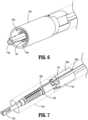
FIGS. 1A and1B , asurgical stapling apparatus 10 of this disclosure includes a housing assembly 12 (which may include one or more handles that may be manually actuatable to fire surgical stapling apparatus 10) and anelongated shaft assembly 14 that is removably secured tohousing assembly 12.Elongated shaft assembly 14 extends distally tohousing assembly 12 and defines a longitudinal axis "X" therealong.Elongated shaft assembly 14 includes anadapter assembly 100 having a proximal end portion removably secured tohousing assembly 12.Elongated shaft assembly 14 further includes aloading unit 200 that is removably secured to a distal end portion ofadapter assembly 100 and which extends distally fromadapter assembly 100 to anend effector 300.Loading unit 200 may be disposable and/or include one or more disposable components.End effector 300 ofloading unit 200 includes ananvil assembly 302 and acartridge assembly 304 that houses a plurality of staples (not shown) in a reload orcartridge 306 thereof that may be selectively replaceable.Anvil assembly 302 includes ananvil 302a against which the plurality of staples is formed upon a firing ofsurgical stapling apparatus 10.End effector 300 further includes one ormore sensors 308 disposed in electrical communication withhousing assembly 12.Sensors 308 may include, for example, a strain gauge, a cartridge ID sensor, a near field communications (NFC) antenna, etc.Sensors 308 may be disposed within one or both ofanvil assembly 302 andcartridge assembly 304.Sensors 308 are configured to electrically communicate withhousing assembly 12 regarding data/information regarding theend effector 300 and/or tissue engaged byend effector 300. For instance, such data/information may relate to tissue thickness, clamp force, firing force, etc. Housing assembly 12 ofsurgical stapling apparatus 10 includes ahousing 12a configured for selective removable receipt of arechargeable battery 12b.Battery 12b is configured to supply power to electrical components ofsurgical stapling apparatus 10.Housing 12a supports acontroller 12c (e.g., a circuit board) therein that is configured to control various operations ofsurgical stapling apparatus 10, and which includes any number of electronic components such asmemory 12d, aprocessor 12e, anetwork interface 12f, and/or other input/output modules 12g.Controller 12c may be coupled to a local or remote display device (not shown) for outputting information and/or data such as a condition of components ofsurgical stapling apparatus 10 and/or tissue grasped byend effector 300.Surgical stapling apparatus 10 further includes adrive mechanism 12h configured to drive mechanical and/or electrical components such as rotatable shafts and/or gear components (not shown) withinhousing 12a in order to perform various operations ofsurgical stapling apparatus 10. For instance,drive mechanism 12h may be operable to selectively rotate and/orarticulate end effector 300 about, and/or relative to, the longitudinal axis "X" ofsurgical stapling apparatus 10, as indicated by arrows "A" and "B," respectively; to selectively moveanvil assembly 302 relative to the cartridge assembly 301 and/or vice versa, as indicated by arrows "C" to selectively clamp tissue; and/or to firesurgical stapling apparatus 10 for fastening and/or cutting the clamped tissue.Battery 12b,controller 12c, and/or drivemechanism 12h may be operably coupled to one ormore actuators surgical stapling apparatus 10 such as those described above.- Turning now to
FIGS. 2-15 ,adapter assembly 100 ofelongated shaft assembly 14 includes anouter housing 110 and supports adrive assembly 112 therein.Outer housing 110 has a proximalouter housing 110a and a tubularouter housing 110b that extends distally from proximalouter housing 110a to adistal tip housing 110c. Proximalouter housing 110a supports anelectrical assembly 110d and a plurality ofdrive couplers 110c that electromechanically couple to drivemechanism 12h ofhousing assembly 12. More specifically,electrical assembly 110d includes, for example, anelectrical port 110z and a printedcircuit board assembly 110y in electrical communication with one another (seeFIG. 2 ).Electrical assembly 110d is configured to electrically communicate with, for example,controller 12c ofhousing assembly 12 whenadapter 100 is coupled tohousing assembly 12 whiledrive couplers 110c mechanically engagedrive mechanism 12h, which may include, for instance, a plurality of rotatable actuators (shown) to impart mechanical force (e.g., rotational force) throughdrive assembly 112 ofadapter assembly 100. For example, drive assembly 112 ofadapter assembly 100 includes afiring rod 112a that extends distal todistal tip housing 110c and is mechanically engageable with the proximal end portion ofloading unit 200 to impart mechanical force (e.g., linear and/or rotational) ontoend effector 300 for firingend effector 300 whendrive mechanism 12h ofhousing assembly 12 is actuated.Distal tip housing 110c includeslugs 110e (seeFIG. 6 ) extending radially inward from an inner surface ofdistal tip housing 110c and positioned to facilitate locking engagement with a proximal end portion ofloading unit 200.Lugs 110e may be disposed in diametrically opposed relationship to one another. Adapter assembly 100 further supports an adapterelectrical connector assembly 120 that is disposed in electrical communication withelectrical assembly 110d of proximalouter housing 110a. Adapterelectrical connector assembly 120 includes anadapter connector housing 122 that is positioned to receivefiring rod 112a therethrough so that firingrod 112a is rotatable relative toadapter connector housing 122. Adapterelectrical connector assembly 120 further includes anelectronic ring assembly 124 and a seal 126 (e.g., an annular seal or gasket such as an O-ring) that are secured toadapter connector housing 122.- As best seen in
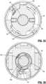
FIGS. 2-7 ,adapter connector housing 122 of adapterelectrical connector assembly 120 is supported within tubularouter housing 110b ofadapter assembly 100.Adapter connector housing 122 includes aproximal base 122a having adistal ledge 122b recessed fromproximal base 122a to enableadapter connector housing 122 to couple to a proximal end portion ofdistal tip housing 110c ofadapter assembly 100.Adapter connector housing 122, which may be wholly or partially non-conductive, further includes aconnector shaft 122c that extends distally fromproximal base 122a for supportingelectronic ring assembly 124 andseal 126.Connector shaft 122c andproximal base 122a define aflex channel 122x (seeFIG. 7 ) along an outer surface thereof for supportingelectronic ring assembly 124 and acentral lumen 123 therethrough for rotatably receivingfiring rod 112a therethrough.Connector shaft 122c includes a mountingfinger 122d having a plurality ofannular ribs 122e that are longitudinally spaced apart along an outer surface of mountingfinger 122d to define ring recesses 122f between adjacentannular ribs 122e for receivingelectronic ring assembly 124.Connector shaft 122c further defines apair alignment notches 122g disposed in diametrical opposed relation to one another (seeFIGS. 4 and12 ) on the outer surface ofconnector shaft 122c and distal to the plurality ofannular ribs 122e to facilitate engagement with loading unit 200 (and to help maintain proper positioning ofribs 122e for isolating electrical contacts).Connector shaft 122c further defines anannular seal channel 122h for mountingseal 126 toadapter connector housing 122 over electronic ring assembly 124 (e.g., overmolded or assembled).Electronic ring assembly 124 includes a plurality of longitudinally spaced apart contact rings 124a, which are conductive (e.g., metallic), that are secured within ring recesses 122f of mountingfinger 122d (e.g., insert molded) and are coupled to aconnector flex assembly 124b (e.g., soldered) that is supported withinflex channel 122x ofadapter connector housing 122.Connector flex assembly 124b, which may be in the form of a flex cable for electrically communicating data and/or power, extends proximally fromadapter connector housing 122 and is disposed in electrical communication withelectrical assembly 110d ofadapter assembly 100. - With reference to
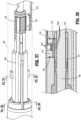
FIGS. 2, 3 , and8-11 ,loading unit 200 ofelongated shaft assembly 14 has atubular shaft 202 that supports a loadingunit drive assembly 205 therein that is configured to couple to drive assembly 112 ofadapter assembly 100 to operateend effector 300. A proximal portion oftubular shaft 202 ofloading unit 200 has a pair ofcurved tines 204 disposed in mirrored relationship with one another (e.g., diametrically opposed) and which extend to a proximal end ofloading unit 200.Tines 204 oftubular shaft 202 are receivable withindistal tip housing 110c ofadapter assembly 100. Thecurved tines 204 define a pair ofouter lug channels 206 for receivinglugs 110e of adapter assembly 100 (seeFIG. 6 ) therein to secureloading unit 200 andadapter assembly 100 together.Outer lug channels 206 ofloading unit 200 include a longitudinally-extendingportion 206a for longitudinally receivinglugs 110e, as indicated by arrows "L" inFIG. 8 , and atransverse portion 206b at a distal end of longitudinally-extendingportion 206a for rotatably receivinglugs 110e therein, as indicated by arrows "R" inFIG. 8 , to lockloading unit 200 andadapter assembly 100 together. Loading unit 200 ofelongated shaft assembly 14 supports a loading unitelectrical connector assembly 210 between the pair ofcurved tines 204. Loading unitelectrical connector assembly 210 extends distally throughtubular shaft 202 for electrically coupling tosensors 308 supported withinend effector tubular body 212a that supports anouter rail 212b.Outer rail 212b defines a series of spring contact recesses 212c therein. The spring contact recesses 212c are longitudinally spaced apart from one another. Spring contact recesses 212c support a series ofspring contacts 212d, which are electrically conductive (e.g., metallic).Outer rail 212b further definesrail channel 212x therein that extends longitudinally alongouter rail 212b.Tubular body 212a defines acentral passage 212e therethrough and which is configured to receive adapterelectrical connector assembly 120 ofadapter assembly 100 therein and firingrod 112a ofadapter assembly 100 therethrough.Tubular body 212a further includes a pair oftabs 212f (seeFIGS. 9 and12 ) extending radially inward from an inner surface oftubular body 212a.Tabs 212f are positioned to engage thepair alignment notches 122g defined inconnector shaft 122c of adapter connector housing 122 (seeFIG. 4 ) to facilitate securement ofloading unit 200 andadapter assembly 100 together.Tubular body 212a further includes adistal tooth 212g which functions as a rotational stop forlugs 110e of adapter assembly 100 (seeFIG. 8 ) and a retention feature that keeps loadingunit connector housing 212 engaged withloading unit 200. Loading unitelectrical connector assembly 210 further includes aseal cap 214, a loadingunit flex assembly 216, which may be in the form of a flex cable, and a seal ring 218 (e.g., an O-ring).Seal cap 214 is mounted inrail channel 212x ofouter rail 212b over a backside of loadingunit flex assembly 216 and is configured to securespring contacts 212d withinouter rail 212b and to stiffen and seal the backside of loadingunit flex assembly 216. Loadingunit flex assembly 216 extends distally throughloading unit 200 to electrically couple tosensors 308 withinend effector 300.Seal ring 218 seats in a distal portion ofcentral passage 212e oftubular body 212a of loading unitelectrical connector assembly 210 to seal thecentral passage 212e oftubular body 212a.- With reference to
FIGS. 8 and11-15 , to mechanical and electricallycouple adapter assembly 100 andloading unit 200 together, thecurved tines 204 oftubular shaft 202 ofloading unit 200 is inserted withindistal tip housing 110c ofadapter assembly 100 so thatlugs 110e ofdistal tip housing 110c translate distally alongouter lug channels 206.Lugs 110e are advanced distally along longitudinally-extendingportion 206a ofouter lug channel 206, as indicated by arrows "L" (seeFIG. 8 ) until longitudinally aligned withtransverse portion 206b ofouter lug channel 206, andtabs 212f oftubular body 212a are longitudinally aligned withalignment notches 122g ofconnector shaft 122c. Then, relative rotation betweenadapter assembly 100 andloading unit 200, as indicated by arrows "RR" shown inFIGS. 13 and 14 , causeslugs 110e to rotate intotransverse portion 206b ofouter lug channel 206, as indicated by arrows "R" inFIG. 8 andtabs 212f to rotate intoalignment notches 122g. In this position,adapter assembly 100 andloading unit 200 are mechanical locked together and electrically coupled together via contact between adapterelectrical connector assembly 120 and loading unitelectrical connector assembly 210 as seen inFIG. 15 so that an electrical circuit is formed fromsensors 308 inend effector 300 throughelongated shaft assembly 14, and to housing assembly 12 (e.g.,controller 12c,battery 12b, etc., thereof.) In this position, adapterelectrical connector assembly 120 and loading unitelectrical assembly 210 are sealed viaseal ring 218 andseal 126. - Once the electrical circuit is created,
surgical stapling apparatus 10 can be used to effectuate a surgical procedure, whereby the electrical circuit can determine and/or analyze data/information may relate to tissue thickness, clamp force, firing force, etc. to help facilitate the efficiency and effectiveness of the surgical procedure.Loading unit 200 can be separated and removed fromadapter assembly 100 as desired, for example, to dispose of and/or replace theloading unit 200 with anotherloading unit 200.Adapter assembly 100 is likewise removable and replaceable with respect toloading unit 200 and/orhousing assembly 12. - Turning now to
FIGS. 16-28 , according to another aspect,adapter assembly 400 and aloading unit 500 can also be removably, electromechanically coupled together similar toadapter 100 andloading unit 200.Adapter assembly 400 includes adapterelectrical connector assembly 410 andloading unit 500 includes loading unitelectrical connector assembly 510. Adapterelectrical connector assembly 410 ofadapter assembly 400 couples toelectrical assembly 110d at the proximal end portion ofadapter assembly 400 and loading unitelectrical connector assembly 510 couples tosensors 308 supported inend effector 300.Adapter assembly 400 supports afiring rod 402 and defines lugslots 404 therein for receivinglugs 502 extending radially outward from the proximal end portion ofloading unit 500.Adapter assembly 400 further includesseal ring 415 supported about firingrod 402 proximal to adapterelectrical connector assembly 410. - As best seen in
FIGS. 19 and 20 , adapterelectrical connector assembly 410 includes aconnector housing 412 and aperipheral seal 414 secured onto connector housing 412 (e.g., overmolded). Adapterelectrical connector assembly 410 further includes a plurality ofspring contacts 416, which are electrically conductive, supported inconnector housing 412 and longitudinally spaced apart from one another.Spring contacts 416 are coupled to a flex cable 418 (e.g., soldered thereto). - With reference to
FIGS. 21 and 22 , loading unitelectrical connector assembly 510 includes aconnector housing 512 that has atubular body 512a.Tubular body 512 defines snap-fit apertures 512b through a sidewall oftubular body 512a.Tubular body 512 further defines acable channel 512c along an outer surface oftubular body 512a. Loading unitelectrical connector assembly 510 further includes a seal 514 (e.g., an O-ring), anelectrical coupler 516 onto which seal 514 mounts, and aflex cable 518.Electrical coupler 516 includes a plurality of longitudinally spaced apartcontract rings 516a, each of which is electrically conductive, and a pair of snap-fit arms 516b flexibly mounted thereto. Snap-fit arms 516b are configured to snap-fit into snap-fit apertures 512b oftubular body 512 to secureelectrical coupler 516 totubular body 512 as seen inFIG. 22 . - With reference to
FIGS. 23-28 , to electromechanicallycouple loading unit 500 toadapter assembly 400,loading unit 500 is axially inserted intoadapter assembly 400 and rotated similar toloading unit 200 andadapter assembly 400, as detailed above, so that loading unitelectrical connector assembly 510 and adapterelectrical connector assembly 410 electrically couple together. - Turning now to
FIGS. 29-32 , according to yet another aspect, a loading unitelectrical connector assembly 600 can be electrically coupled to an adapterelectrical connector assembly 700. Loading unitelectrical connector assembly 600 includes a plurality ofsheet metal contacts 610, each of which is electrically conductive, angularly spaced about atubular body 602 of loading unitelectrical connector assembly 600 and seal 604 supported ontubular body 602.Sheet metal contacts 610 may be angularly and/or longitudinally spaced apart from one another. In aspects,sheet metal contacts 610 may be disposed in a spiral arrangement abouttubular body 602. Adapterelectrical connector assembly 700 includes a plurality of annular contact rings 702, each of which is electrically conductive. The annular contact rings 702 are longitudinally spaced apart along an inner surface of atubular body 701 of adapterelectrical connector assembly 700. Adapterelectrical connector assembly 700 further includes aseal 704 supported therein. - With reference to
FIGS. 33-36 , according to still another aspect, a loading unitelectrical connector assembly 800 can be electrically coupled to an adapterelectrical connector assembly 900. Loading unitelectrical connector assembly 800 includes atubular body 802 supporting a plurality of contact rings 804, each of which is electrically conductive, at longitudinally spaced apart locations and aseal 806. Adapterelectrical connector assembly 900 includes atubular body 902 defining acutout 904 that extends longitudinally alongsidewall 902a oftubular body 902. Adapterelectrical connector assembly 900 further includes aseal 906 and acontact insert assembly 908 that is receivable in cutout 907 oftubular body 902. Contactinsert assembly 908 includes anelongate leg 908a and a plurality ofarched contacts 908b, each of which is electrically conductive, longitudinally spaced apart alongelongate leg 908a and receivable withintubular body 902 whenelongate leg 908a is seated incutout 904 oftubular body 902. - Further, the various aspects disclosed herein may also be configured to work with robotic surgical systems and what is commonly referred to as "Telesurgery." Such systems employ various robotic elements to assist the clinician and allow remote operation (or partial remote operation) of surgical instrumentation. Various robotic arms, gears, cams, pulleys, electric and mechanical motors, etc. may be employed for this purpose and may be designed with a robotic surgical system to assist the clinician during the course of an operation or treatment. Such robotic systems may include remotely steerable systems, automatically flexible surgical systems, remotely flexible surgical systems, remotely articulating surgical systems, wireless surgical systems, modular or selectively configurable remotely operated surgical systems, etc.
- The robotic surgical systems may be employed with one or more consoles that are next to the operating theater or located in a remote location. In this instance, one team of clinicians may prep the patient for surgery and configure the robotic surgical system with one or more of the instruments disclosed herein while another clinician (or group of clinicians) remotely controls the instruments via the robotic surgical system. As can be appreciated, a highly skilled clinician may perform multiple operations in multiple locations without leaving his/her remote console which can be both economically advantageous and a benefit to the patient or a series of patients. For a detailed description of exemplary medical work stations and/or components thereof, reference may be made to
U.S. Patent Application Publication No. 2012/0116416 , andPCT Application Publication No. WO2016/025132 . - Moreover, the disclosed electronic structure such as the electronic assembly and/or controllers, can include any suitable electrical components for operating the disclosed surgical stapling apparatus or components thereof. Such electrical components can include, for example, one or more controllers and/or circuitry, which may include or be coupled to one or more printed circuit boards. As used herein, the term "controller" includes "processor," "digital processing device" and like terms, and are used to indicate a microprocessor or central processing unit (CPU). The CPU is the electronic circuitry within a computer that carries out the instructions of a computer program by performing the basic arithmetic, logical, control and input/output (I/O) operations specified by the instructions, and by way of non-limiting examples, include server computers. In some aspects, the controller includes an operating system configured to perform executable instructions. The operating system is, for example, software, including programs and data, which manages hardware of the disclosed surgical stapling apparatus and provides services for execution of applications for use with the disclosed surgical stapling apparatus. Those of skill in the art will recognize that suitable server operating systems include, by way of non-limiting examples, FreeBSD, OpenBSD, NetBSD®, Linux, Apple® Mac OS X Server®, Oracle® Solaris®, Windows Server®, and Novell® NetWare®. In some aspects, the operating system is provided by cloud computing.
- In some aspects, the term "controller" may be used to indicate a device that controls the transfer of data from a computer or computing device to a peripheral or separate device and vice versa, and/or a mechanical and/or electromechanical device (e.g., a lever, knob, etc.) that mechanically operates and/or actuates a peripheral or separate device.
- In aspects, the controller includes a storage and/or memory device. The storage and/or memory device is one or more physical apparatus used to store data or programs on a temporary or permanent basis. In some aspects, the controller includes volatile memory and requires power to maintain stored information. In various aspects, the controller includes non-volatile memory and retains stored information when it is not powered. In some aspects, the non-volatile memory includes flash memory. In certain aspects, the non-volatile memory includes dynamic random-access memory (DRAM). In some aspects, the non-volatile memory includes ferroelectric random access memory (FRAM). In various aspects, the non-volatile memory includes phase-change random access memory (PRAM). In certain aspects, the controller is a storage device including, by way of non-limiting examples, CD-ROMs, DVDs, flash memory devices, magnetic disk drives, magnetic tapes drives, optical disk drives, and cloud computing based storage. In various aspects, the storage and/or memory device is a combination of devices such as those disclosed herein.
- In some aspects, the controller includes a display to send visual information to a user. In various aspects, the display is a cathode ray tube (CRT). In various aspects, the display is a liquid crystal display (LCD). In certain aspects, the display is a thin film transistor liquid crystal display (TFT-LCD). In aspects, the display is an organic light emitting diode (OLED) display. In certain aspects, on OLED display is a passive-matrix OLED (PMOLED) or active-matrix OLED (AMOLED) display. In aspects, the display is a plasma display. In certain aspects, the display is a video projector. In various aspects, the display is interactive (e.g., having a touch screen or a sensor such as a camera, a 3D sensor, a LiDAR, a radar, etc.) that can detect user interactions/gestures/responses and the like. In some aspects, the display is a combination of devices such as those disclosed herein.
- The controller may include or be coupled to a server and/or a network. As used herein, the term "server" includes "computer server," "central server," "main server," and like terms to indicate a computer or device on a network that manages the surgical stapling apparatus, components thereof, and/or resources thereof. As used herein, the term "network" can include any network technology including, for instance, a cellular data network, a wired network, a fiber optic network, a satellite network, and/or an IEEE 802.11a/b/g/n/ac wireless network, among others.
- In various aspects, the controller can be coupled to a mesh network. As used herein, a "mesh network" is a network topology in which each node relays data for the network. All mesh nodes cooperate in the distribution of data in the network. It can be applied to both wired and wireless networks. Wireless mesh networks can be considered a type of "Wireless ad hoc" network. Thus, wireless mesh networks are closely related to Mobile ad hoc networks (MANETs). Although MANETs are not restricted to a specific mesh network topology, Wireless ad hoc networks or MANETs can take any form of network topology. Mesh networks can relay messages using either a flooding technique or a routing technique. With routing, the message is propagated along a path by hopping from node to node until it reaches its destination. To ensure that all its paths are available, the network must allow for continuous connections and must reconfigure itself around broken paths, using self-healing algorithms such as Shortest Path Bridging. Self-healing allows a routing-based network to operate when a node breaks down or when a connection becomes unreliable. As a result, the network is typically quite reliable, as there is often more than one path between a source and a destination in the network. This concept can also apply to wired networks and to software interaction. A mesh network whose nodes are all connected to each other is a fully connected network.
- In some aspects, the controller may include one or more modules. As used herein, the term "module" and like terms are used to indicate a self-contained hardware component of the central server, which in turn includes software modules. In software, a module is a part of a program. Programs are composed of one or more independently developed modules that are not combined until the program is linked. A single module can contain one or several routines, or sections of programs that perform a particular task.
- As used herein, the controller includes software modules for managing various aspects and functions of the disclosed surgical stapling apparatus or components thereof.
- The disclosed surgical stapling apparatus may also utilize one or more controllers to receive various information and transform the received information to generate an output. The controller may include any type of computing device, computational circuit, or any type of processor or processing circuit capable of executing a series of instructions that are stored in memory. The controller may include multiple processors and/or multicore central processing units (CPUs) and may include any type of processor, such as a microprocessor, digital signal processor, microcontroller, programmable logic device (PLD), field programmable gate array (FPGA), or the like. The controller may also include a memory to store data and/or instructions that, when executed by the one or more processors, cause the one or more processors to perform one or more methods and/or algorithms.
- Any of the herein described methods, programs, algorithms or codes may be converted to, or expressed in, a programming language or computer program. The terms "programming language" and "computer program," as used herein, each include any language used to specify instructions to a computer, and include (but is not limited to) the following languages and their derivatives: Assembler, Basic, Batch files, BCPL, C, C+, C++, Delphi, Fortran, Java, JavaScript, machine code, operating system command languages, Pascal, Perl, PL1, scripting languages, Visual Basic, metalanguages which themselves specify programs, and all first, second, third, fourth, fifth, or further generation computer languages. Also included are database and other data schemas, and any other meta-languages. No distinction is made between languages which are interpreted, compiled, or use both compiled and interpreted approaches. No distinction is made between compiled and source versions of a program. Thus, reference to a program, where the programming language could exist in more than one state (such as source, compiled, object, or linked) is a reference to any and all such states. Reference to a program may encompass the actual instructions and/or the intent of those instructions.
- As can be appreciated, securement of any of the components of the disclosed apparatus can be effectuated using known securement techniques such welding, crimping, gluing, fastening, etc. Also, any of the disclosed structure can include any suitable conductive material (e.g., metallic), semi-conductive material (e.g., silicone), and/or non-conductive/insulative material (e.g., plastic).
- Persons skilled in the art will understand that the structures and methods specifically described herein and illustrated in the accompanying figures are non-limiting exemplary aspects, and that the description, disclosure, and figures should be construed merely as exemplary of particular aspects. It is to be understood, therefore, that this disclosure is not limited to the precise aspects described, and that various other changes and modifications may be effectuated by one skilled in the art without departing from the scope of the disclosure. Additionally, it is envisioned that the elements and features illustrated or described in connection with one exemplary aspect may be combined with the elements and features of another without departing from the scope of this disclosure, and that such modifications and variations are also intended to be included within the scope of this disclosure. Indeed, any combination of any of the disclosed elements and features is within the scope of this disclosure. Accordingly, the subject matter of this disclosure is not to be limited by what has been particularly shown and described.
Claims (7)
- A surgical stapling apparatus (10), comprising:a housing assembly (12); andan elongated shaft assembly (14) selectively attachable to the housing assembly, the elongated shaft assembly including:an adapter assembly (100) extending distally to a distal tip Z housing (110c), the distal tip housing supporting an adapter electrical connector assembly (120) therein; anda loading unit (200) selectively attachable to the adapter assembly and extending distally to an end effector (300) supporting at least one sensor (308) therein, the loading unit supporting a loading unit electrical connector assembly (210) therein, the loading unit electrical connector assembly positioned to contact the adapter electrical connector assembly when the adapter assembly and the loading unit are coupled together to electrically couple the at least one sensor to the housing assembly wherein the adapter electrical connector assembly includes an adapter connector housing (122) that rotatably supports a firing rod (112a) therethrough; wherein the adapter electrical connector assembly includes an electronic ring assembly (124) that is supported on the adapter connector housing;charaterized in thatthe adapter connector housing includes a connector shaft (122c) that supports the electronic ring assembly thereon; wherein the connector shaft defines a plurality of annular ribs (122e) and a plurality of ring recesses (122f) disposed between the annular ribs, the plurality of ring recesses and the plurality of annual ribs positioned to support a plurality of contact rings of the electronic ring assembly.
- The surgical stapling apparatus of claim 1, wherein the at least one sensor configured to measure data including thickness of tissue clamped by the end effector, clamp force of the end effector, or firing force of the end effector.
- The surgical stapling apparatus of claim 1, wherein the plurality of contact rings is electrically coupled to a flex cable (418) supported by a channel defined within the adapter connector housing:
and/or wherein the loading unit electrical connector assembly includes a loading unit connector housing that supports a plurality of spring contacts (212d) positioned to contact the plurality of contact rings of the electronic ring assembly; preferably wherein the plurality of spring contacts is electrically coupled to the at least one sensor. - The surgical stapling apparatus of any preceding claim, wherein the adapter electrical connector assembly and the loading unit electrical connector assembly are sealed within elongated shaft assembly when electrically coupled together.
- A surgical stapling apparatus, as claimed in claim 1 wherein :
wherein the loading unit is selectively electrically connectable to the adapter assembly by relative translating and rotating movement between the loading unit and the adapter assembly, the loading unit electrical connector assembly positioned to receive the adapter electrical connector assembly to cause the adapter assembly and the loading unit to electrically couple together in response to the translating and rotating movement. - The surgical stapling apparatus of claim 5, wherein the at least one sensor is configured to measure data including thickness of tissue clamped by the end effector, clamp force of the end effector, or firing force of the end effector.
- The surgical stapling apparatus of claim 6, wherein the loading unit defines a lug channel (206) positioned to receive a lug of the adapter assembly, the lug channel having a longitudinally-extending portion to enable translating movement of the lug therethrough and a transverse portion to enable rotating movement of the lug therethrough.
Applications Claiming Priority (2)
| Application Number | Priority Date | Filing Date | Title |
|---|---|---|---|
| US202063037274P | 2020-06-10 | 2020-06-10 | |
| US17/321,855US12016557B2 (en) | 2020-06-10 | 2021-05-17 | Sealed electrical connection between surgical loading unit and adapter |
Publications (2)
| Publication Number | Publication Date |
|---|---|
| EP3922193A1 EP3922193A1 (en) | 2021-12-15 |
| EP3922193B1true EP3922193B1 (en) | 2025-01-22 |
Family
ID=78822791
Family Applications (1)
| Application Number | Title | Priority Date | Filing Date |
|---|---|---|---|
| EP21178601.7AActiveEP3922193B1 (en) | 2020-06-10 | 2021-06-09 | Sealed electrical connection between surgical loading unit and adapter |
Country Status (5)
| Country | Link |
|---|---|
| US (2) | US12016557B2 (en) |
| EP (1) | EP3922193B1 (en) |
| JP (1) | JP7685880B2 (en) |
| CN (1) | CN113768567A (en) |
| CA (1) | CA3120753A1 (en) |
Families Citing this family (3)
| Publication number | Priority date | Publication date | Assignee | Title |
|---|---|---|---|---|
| US11684362B2 (en)* | 2021-06-07 | 2023-06-27 | Covidien Lp | Handheld electromechanical surgical system |
| US11862884B2 (en) | 2021-08-16 | 2024-01-02 | Covidien Lp | Surgical instrument with electrical connection |
| US12390219B2 (en)* | 2023-11-06 | 2025-08-19 | Cilag Gmbh International | Surgical stapler with clamp force sensor |
Family Cites Families (389)
| Publication number | Priority date | Publication date | Assignee | Title |
|---|---|---|---|---|
| US2957353A (en) | 1958-08-26 | 1960-10-25 | Teleflex Inc | Connector |
| US3111328A (en) | 1961-07-03 | 1963-11-19 | Rito Vincent L J Di | Multiuse adapter for manipulators |
| US3734515A (en) | 1971-01-29 | 1973-05-22 | Thor Power Tool Co | Power wrench with interchangeable adapters |
| US3695058A (en) | 1971-05-26 | 1972-10-03 | Marvin W Keith Jr | Flexible link rotatable drive coupling |
| US3759336A (en) | 1972-01-21 | 1973-09-18 | D Marcovitz | Interchangeable power operated tools |
| US4162399A (en) | 1977-09-16 | 1979-07-24 | Bei Electronics, Inc. | Optical encoder with fiber optics |
| US4606343A (en) | 1980-08-18 | 1986-08-19 | United States Surgical Corporation | Self-powered surgical fastening instrument |
| US4705038A (en) | 1985-01-23 | 1987-11-10 | Dyonics, Inc. | Surgical system for powered instruments |
| US4722685A (en) | 1985-05-30 | 1988-02-02 | Estrada Juan M De | Tool for adapting a portable lathe to treat the back molar teeth of horses |
| US4823807A (en) | 1988-02-11 | 1989-04-25 | Board Of Regents, Univ. Of Texas System | Device for non-invasive diagnosis and monitoring of articular and periarticular pathology |
| US4874181A (en) | 1988-05-31 | 1989-10-17 | Hsu Shing Wang | Coupling member for securing a drilling head to the rotatable rod of a pneumatic tool body |
| US5301061A (en) | 1989-07-27 | 1994-04-05 | Olympus Optical Co., Ltd. | Endoscope system |
| US5152744A (en) | 1990-02-07 | 1992-10-06 | Smith & Nephew Dyonics | Surgical instrument |
| JP3034019B2 (en) | 1990-11-26 | 2000-04-17 | 旭光学工業株式会社 | Endoscope tip |
| US5129570A (en) | 1990-11-30 | 1992-07-14 | Ethicon, Inc. | Surgical stapler |
| US5413267A (en) | 1991-05-14 | 1995-05-09 | United States Surgical Corporation | Surgical stapler with spent cartridge sensing and lockout means |
| US5129118A (en) | 1991-07-29 | 1992-07-14 | Walmesley Mark W | Accessory tool apparatus for use on power drills |
| US5326013A (en) | 1991-10-18 | 1994-07-05 | United States Surgical Corporation | Self contained gas powered surgical apparatus |
| US5443198A (en) | 1991-10-18 | 1995-08-22 | United States Surgical Corporation | Surgical fastener applying apparatus |
| US5478003A (en) | 1991-10-18 | 1995-12-26 | United States Surgical Corporation | Surgical apparatus |
| US5312023A (en) | 1991-10-18 | 1994-05-17 | United States Surgical Corporation | Self contained gas powered surgical apparatus |
| US5197649A (en) | 1991-10-29 | 1993-03-30 | The Trustees Of Columbia University In The City Of New York | Gastrointestinal endoscoptic stapler |
| US5383874A (en) | 1991-11-08 | 1995-01-24 | Ep Technologies, Inc. | Systems for identifying catheters and monitoring their use |
| US5433721A (en) | 1992-01-17 | 1995-07-18 | Ethicon, Inc. | Endoscopic instrument having a torsionally stiff drive shaft for applying fasteners to tissue |
| US5383880A (en) | 1992-01-17 | 1995-01-24 | Ethicon, Inc. | Endoscopic surgical system with sensing means |
| US5350355A (en) | 1992-02-14 | 1994-09-27 | Automated Medical Instruments, Inc. | Automated surgical instrument |
| US5389098A (en) | 1992-05-19 | 1995-02-14 | Olympus Optical Co., Ltd. | Surgical device for stapling and/or fastening body tissues |
| US5658300A (en) | 1992-06-04 | 1997-08-19 | Olympus Optical Co., Ltd. | Tissue fixing surgical instrument, tissue-fixing device, and method of fixing tissues |
| US5609560A (en) | 1992-08-19 | 1997-03-11 | Olympus Optical Co., Ltd. | Medical operation device control system for controlling a operation devices accessed respectively by ID codes |
| US5601224A (en) | 1992-10-09 | 1997-02-11 | Ethicon, Inc. | Surgical instrument |
| US5662662A (en) | 1992-10-09 | 1997-09-02 | Ethicon Endo-Surgery, Inc. | Surgical instrument and method |
| US5431323A (en) | 1992-10-09 | 1995-07-11 | Ethicon, Inc. | Endoscopic surgical instrument with pivotable and rotatable staple cartridge |
| US5626587A (en) | 1992-10-09 | 1997-05-06 | Ethicon Endo-Surgery, Inc. | Method for operating a surgical instrument |
| US5400267A (en) | 1992-12-08 | 1995-03-21 | Hemostatix Corporation | Local in-device memory feature for electrically powered medical equipment |
| US5540706A (en) | 1993-01-25 | 1996-07-30 | Aust; Gilbert M. | Surgical instrument |
| US5540375A (en) | 1993-04-20 | 1996-07-30 | United States Surgical Corporation | Endoscopic stapler |
| US5467911A (en) | 1993-04-27 | 1995-11-21 | Olympus Optical Co., Ltd. | Surgical device for stapling and fastening body tissues |
| CA2124109A1 (en) | 1993-05-24 | 1994-11-25 | Mark T. Byrne | Endoscopic surgical instrument with electromagnetic sensor |
| US5542594A (en) | 1993-10-06 | 1996-08-06 | United States Surgical Corporation | Surgical stapling apparatus with biocompatible surgical fabric |
| US5487499A (en) | 1993-10-08 | 1996-01-30 | United States Surgical Corporation | Surgical apparatus for applying surgical fasteners including a counter |
| US5476379A (en) | 1993-11-04 | 1995-12-19 | Disel; Jimmy D. | Illumination system and connector assembly for a dental handpiece |
| US5782397A (en) | 1994-01-04 | 1998-07-21 | Alpha Surgical Technologies, Inc. | Stapling device |
| US6165169A (en) | 1994-03-04 | 2000-12-26 | Ep Technologies, Inc. | Systems and methods for identifying the physical, mechanical, and functional attributes of multiple electrode arrays |
| US5526822A (en) | 1994-03-24 | 1996-06-18 | Biopsys Medical, Inc. | Method and apparatus for automated biopsy and collection of soft tissue |
| US5529235A (en) | 1994-04-28 | 1996-06-25 | Ethicon Endo-Surgery, Inc. | Identification device for surgical instrument |
| US5553675A (en) | 1994-06-10 | 1996-09-10 | Minnesota Mining And Manufacturing Company | Orthopedic surgical device |
| EP0699418A1 (en) | 1994-08-05 | 1996-03-06 | United States Surgical Corporation | Self-contained powered surgical apparatus |
| US5779130A (en) | 1994-08-05 | 1998-07-14 | United States Surgical Corporation | Self-contained powered surgical apparatus |
| EP0705571A1 (en) | 1994-10-07 | 1996-04-10 | United States Surgical Corporation | Self-contained powered surgical apparatus |
| US5549637A (en) | 1994-11-10 | 1996-08-27 | Crainich; Lawrence | Articulated medical instrument |
| US5868760A (en) | 1994-12-07 | 1999-02-09 | Mcguckin, Jr.; James F. | Method and apparatus for endolumenally resectioning tissue |
| US5632432A (en) | 1994-12-19 | 1997-05-27 | Ethicon Endo-Surgery, Inc. | Surgical instrument |
| US5713505A (en) | 1996-05-13 | 1998-02-03 | Ethicon Endo-Surgery, Inc. | Articulation transmission mechanism for surgical instruments |
| US5704534A (en) | 1994-12-19 | 1998-01-06 | Ethicon Endo-Surgery, Inc. | Articulation assembly for surgical instruments |
| US6321855B1 (en) | 1994-12-29 | 2001-11-27 | George Edward Barnes | Anti-vibration adaptor |
| US5649956A (en) | 1995-06-07 | 1997-07-22 | Sri International | System and method for releasably holding a surgical instrument |
| US5782396A (en) | 1995-08-28 | 1998-07-21 | United States Surgical Corporation | Surgical stapler |
| US6032849A (en) | 1995-08-28 | 2000-03-07 | United States Surgical | Surgical stapler |
| US5762256A (en) | 1995-08-28 | 1998-06-09 | United States Surgical Corporation | Surgical stapler |
| CA2206156A1 (en) | 1995-09-15 | 1997-04-03 | Robert Lee Thompson | Surgical/diagnostic imaging device |
| US7141049B2 (en) | 1999-03-09 | 2006-11-28 | Thermage, Inc. | Handpiece for treatment of tissue |
| US5820009A (en) | 1996-02-20 | 1998-10-13 | Richard-Allan Medical Industries, Inc. | Articulated surgical instrument with improved jaw closure mechanism |
| US6010054A (en) | 1996-02-20 | 2000-01-04 | Imagyn Medical Technologies | Linear stapling instrument with improved staple cartridge |
| US6699177B1 (en) | 1996-02-20 | 2004-03-02 | Computer Motion, Inc. | Method and apparatus for performing minimally invasive surgical procedures |
| US5810240A (en) | 1996-03-15 | 1998-09-22 | United States Surgical Corporation | Surgical fastener applying device |
| US6119913A (en) | 1996-06-14 | 2000-09-19 | Boston Scientific Corporation | Endoscopic stapler |
| US6017354A (en) | 1996-08-15 | 2000-01-25 | Stryker Corporation | Integrated system for powered surgical tools |
| US6129547A (en) | 1997-05-06 | 2000-10-10 | Ballard Medical Products | Oral care system |
| WO1999007441A1 (en) | 1997-08-11 | 1999-02-18 | Mayer Paul W | Motorized motion-canceling suture tool holder |
| US6434507B1 (en) | 1997-09-05 | 2002-08-13 | Surgical Navigation Technologies, Inc. | Medical instrument and method for use with computer-assisted image guided surgery |
| US5865361A (en) | 1997-09-23 | 1999-02-02 | United States Surgical Corporation | Surgical stapling apparatus |
| US5863159A (en) | 1997-12-12 | 1999-01-26 | Lasko; Leonard J. | Drill angle attachment coupling |
| EP1056388B1 (en) | 1998-02-19 | 2004-12-22 | California Institute Of Technology | Apparatus for providing spherical viewing during endoscopic procedures |
| US6239732B1 (en) | 1998-04-13 | 2001-05-29 | Dallas Semiconductor Corporation | One-wire device with A-to-D converter |
| US6126058A (en) | 1998-06-19 | 2000-10-03 | Scimed Life Systems, Inc. | Method and device for full thickness resectioning of an organ |
| US6256859B1 (en) | 1998-09-25 | 2001-07-10 | Sherwood Services Ag | Method of manufacturing an aspiring tool |
| US5993454A (en) | 1998-09-29 | 1999-11-30 | Stryker Corporation | Drill attachment for a surgical drill |
| US7238021B1 (en) | 1998-12-03 | 2007-07-03 | Johnson Gary E | Powered cutting surface with protective guard for equine teeth |
| US6860892B1 (en) | 1999-05-28 | 2005-03-01 | General Surgical Innovations, Inc. | Specially shaped balloon device for use in surgery and method of use |
| US6443973B1 (en) | 1999-06-02 | 2002-09-03 | Power Medical Interventions, Inc. | Electromechanical driver device for use with anastomosing, stapling, and resecting instruments |
| US6793652B1 (en) | 1999-06-02 | 2004-09-21 | Power Medical Interventions, Inc. | Electro-mechanical surgical device |
| US8025199B2 (en) | 2004-02-23 | 2011-09-27 | Tyco Healthcare Group Lp | Surgical cutting and stapling device |
| US6716233B1 (en) | 1999-06-02 | 2004-04-06 | Power Medical Interventions, Inc. | Electromechanical driver and remote surgical instrument attachment having computer assisted control capabilities |
| US8241322B2 (en) | 2005-07-27 | 2012-08-14 | Tyco Healthcare Group Lp | Surgical device |
| US7951071B2 (en) | 1999-06-02 | 2011-05-31 | Tyco Healthcare Group Lp | Moisture-detecting shaft for use with an electro-mechanical surgical device |
| US6264087B1 (en) | 1999-07-12 | 2001-07-24 | Powermed, Inc. | Expanding parallel jaw device for use with an electromechanical driver device |
| US7032798B2 (en) | 1999-06-02 | 2006-04-25 | Power Medical Interventions, Inc. | Electro-mechanical surgical device |
| US6981941B2 (en) | 1999-06-02 | 2006-01-03 | Power Medical Interventions | Electro-mechanical surgical device |
| US6491201B1 (en) | 2000-02-22 | 2002-12-10 | Power Medical Interventions, Inc. | Fluid delivery mechanism for use with anastomosing, stapling, and resecting instruments |
| US6315184B1 (en) | 1999-06-02 | 2001-11-13 | Powermed, Inc. | Stapling device for use with an electromechanical driver device for use with anastomosing, stapling, and resecting instruments |
| US6451007B1 (en) | 1999-07-29 | 2002-09-17 | Dale E. Koop | Thermal quenching of tissue |
| US6611793B1 (en) | 1999-09-07 | 2003-08-26 | Scimed Life Systems, Inc. | Systems and methods to identify and disable re-use single use devices based on detecting environmental changes |
| US6368324B1 (en) | 1999-09-24 | 2002-04-09 | Medtronic Xomed, Inc. | Powered surgical handpiece assemblies and handpiece adapter assemblies |
| US6348061B1 (en) | 2000-02-22 | 2002-02-19 | Powermed, Inc. | Vessel and lumen expander attachment for use with an electromechanical driver device |
| US6488197B1 (en) | 2000-02-22 | 2002-12-03 | Power Medical Interventions, Inc. | Fluid delivery device for use with anastomosing resecting and stapling instruments |
| US7770773B2 (en) | 2005-07-27 | 2010-08-10 | Power Medical Interventions, Llc | Surgical device |
| US6533157B1 (en) | 2000-02-22 | 2003-03-18 | Power Medical Interventions, Inc. | Tissue stapling attachment for use with an electromechanical driver device |
| US8016855B2 (en) | 2002-01-08 | 2011-09-13 | Tyco Healthcare Group Lp | Surgical device |
| JP3897962B2 (en) | 2000-07-19 | 2007-03-28 | 株式会社モリタ製作所 | Identification-type instrument body, identification-type adapter, identification-type tube, and medical device using these |
| AU2001288462A1 (en) | 2000-08-30 | 2002-03-13 | Cerebral Vascular Applications Inc. | Medical instrument |
| US6817508B1 (en) | 2000-10-13 | 2004-11-16 | Tyco Healthcare Group, Lp | Surgical stapling device |
| US7334717B2 (en) | 2001-10-05 | 2008-02-26 | Tyco Healthcare Group Lp | Surgical fastener applying apparatus |
| US6716226B2 (en) | 2001-06-25 | 2004-04-06 | Inscope Development, Llc | Surgical clip |
| US20050004559A1 (en) | 2003-06-03 | 2005-01-06 | Senorx, Inc. | Universal medical device control console |
| US8313496B2 (en) | 2001-02-02 | 2012-11-20 | Lsi Solutions, Inc. | System for endoscopic suturing |
| US7699835B2 (en) | 2001-02-15 | 2010-04-20 | Hansen Medical, Inc. | Robotically controlled surgical instruments |
| US7905897B2 (en) | 2001-03-14 | 2011-03-15 | Tyco Healthcare Group Lp | Trocar device |
| ATE551955T1 (en) | 2001-04-20 | 2012-04-15 | Tyco Healthcare | SURGICAL DEVICE HAVING BIPOLAR OR ULTRASONIC FEATURES |
| AU2002315397A1 (en) | 2001-06-20 | 2003-01-08 | Power Medical Interventions, Inc. | A method and system for integrated medical tracking |
| CA2814279C (en) | 2001-06-22 | 2015-12-29 | Tyco Healthcare Group Lp | Electro-mechanical surgical device with data memory unit |
| US7044911B2 (en) | 2001-06-29 | 2006-05-16 | Philometron, Inc. | Gateway platform for biological monitoring and delivery of therapeutic compounds |
| EP2314233B1 (en) | 2001-08-08 | 2013-06-12 | Stryker Corporation | A surgical tool system with an intermediate attachment located between the handpiece and an accessory or an implant, the attachment able to transmit energy from the handpiece to the accessory or the implant and the transmission of data signals from the accessory or implant to the handpiece |
| DE10147145C2 (en) | 2001-09-25 | 2003-12-18 | Kunz Reiner | Multi-function instrument for micro-invasive surgery |
| EP1432358B1 (en) | 2001-10-05 | 2015-08-12 | Covidien LP | Surgical stapling device |
| US10285694B2 (en) | 2001-10-20 | 2019-05-14 | Covidien Lp | Surgical stapler with timer and feedback display |
| US7464847B2 (en) | 2005-06-03 | 2008-12-16 | Tyco Healthcare Group Lp | Surgical stapler with timer and feedback display |
| US6783533B2 (en) | 2001-11-21 | 2004-08-31 | Sythes Ag Chur | Attachable/detachable reaming head for surgical reamer |
| EP1453432B1 (en) | 2001-12-04 | 2012-08-01 | Tyco Healthcare Group LP | System and method for calibrating a surgical instrument |
| IL148702A (en) | 2002-03-14 | 2008-04-13 | Innoventions Inc | Insertion and retrieval system for inflatable devices |
| WO2003090630A2 (en) | 2002-04-25 | 2003-11-06 | Tyco Healthcare Group, Lp | Surgical instruments including micro-electromechanical systems (mems) |
| CA2489727C (en) | 2002-06-14 | 2011-04-26 | Power Medical Interventions, Inc. | Surgical device |
| US20030038938A1 (en) | 2002-06-20 | 2003-02-27 | Jung Wayne D. | Apparatus and method for measuring optical characteristics of an object or material |
| US8182494B1 (en) | 2002-07-31 | 2012-05-22 | Cardica, Inc. | Minimally-invasive surgical system |
| US6645218B1 (en) | 2002-08-05 | 2003-11-11 | Endius Incorporated | Surgical instrument |
| US20040176751A1 (en) | 2002-08-14 | 2004-09-09 | Endovia Medical, Inc. | Robotic medical instrument system |
| AU2003275336A1 (en) | 2002-09-30 | 2004-04-23 | Power Medical Interventions, Inc. | Self-contained sterilizable surgical system |
| AU2003279854B2 (en) | 2002-10-04 | 2008-12-18 | Covidien Lp | Tool assembly for a surgical stapling device |
| CA2500785C (en) | 2002-10-04 | 2011-04-26 | Philip C. Roy | Pneumatic powered surgical stapling device |
| US7559927B2 (en) | 2002-12-20 | 2009-07-14 | Medtronic Xomed, Inc. | Surgical instrument with telescoping attachment |
| JP2004208922A (en) | 2002-12-27 | 2004-07-29 | Olympus Corp | Medical apparatus, medical manipulator and control process for medical apparatus |
| US20040243151A1 (en) | 2003-04-29 | 2004-12-02 | Demmy Todd L. | Surgical stapling device with dissecting tip |
| US20070084897A1 (en) | 2003-05-20 | 2007-04-19 | Shelton Frederick E Iv | Articulating surgical stapling instrument incorporating a two-piece e-beam firing mechanism |
| US7380696B2 (en) | 2003-05-20 | 2008-06-03 | Ethicon Endo-Surgery, Inc. | Articulating surgical stapling instrument incorporating a two-piece E-beam firing mechanism |
| US7143923B2 (en) | 2003-05-20 | 2006-12-05 | Ethicon Endo-Surgery, Inc. | Surgical stapling instrument having a firing lockout for an unclosed anvil |
| US7140528B2 (en) | 2003-05-20 | 2006-11-28 | Ethicon Endo-Surgery, Inc. | Surgical stapling instrument having an electroactive polymer actuated single lockout mechanism for prevention of firing |
| US7380695B2 (en) | 2003-05-20 | 2008-06-03 | Ethicon Endo-Surgery, Inc. | Surgical stapling instrument having a single lockout mechanism for prevention of firing |
| US6988649B2 (en) | 2003-05-20 | 2006-01-24 | Ethicon Endo-Surgery, Inc. | Surgical stapling instrument having a spent cartridge lockout |
| US7044352B2 (en) | 2003-05-20 | 2006-05-16 | Ethicon Endo-Surgery, Inc. | Surgical stapling instrument having a single lockout mechanism for prevention of firing |
| EP2591820B1 (en) | 2003-05-21 | 2015-02-18 | The Johns Hopkins University | Devices and systems for minimally invasive surgery of the throat and other portions of mammalian body |
| EP1635712B1 (en) | 2003-06-20 | 2015-09-30 | Covidien LP | Surgical stapling device |
| US7111769B2 (en) | 2003-07-09 | 2006-09-26 | Ethicon Endo-Surgery, Inc. | Surgical instrument incorporating an articulation mechanism having rotation about the longitudinal axis |
| US6964363B2 (en) | 2003-07-09 | 2005-11-15 | Ethicon Endo-Surgery, Inc. | Surgical stapling instrument having articulation joint support plates for supporting a firing bar |
| US6981628B2 (en) | 2003-07-09 | 2006-01-03 | Ethicon Endo-Surgery, Inc. | Surgical instrument with a lateral-moving articulation control |
| US7055731B2 (en) | 2003-07-09 | 2006-06-06 | Ethicon Endo-Surgery Inc. | Surgical stapling instrument incorporating a tapered firing bar for increased flexibility around the articulation joint |
| JP4398813B2 (en) | 2003-07-18 | 2010-01-13 | ヤーマン株式会社 | Skin care equipment |
| US6959852B2 (en) | 2003-09-29 | 2005-11-01 | Ethicon Endo-Surgery, Inc. | Surgical stapling instrument with multistroke firing incorporating an anti-backup mechanism |
| US6905057B2 (en) | 2003-09-29 | 2005-06-14 | Ethicon Endo-Surgery, Inc. | Surgical stapling instrument incorporating a firing mechanism having a linked rack transmission |
| US7364061B2 (en) | 2003-09-29 | 2008-04-29 | Ethicon Endo-Surgery, Inc. | Surgical stapling instrument incorporating a multistroke firing position indicator and retraction mechanism |
| US8770459B2 (en) | 2003-10-17 | 2014-07-08 | Covidien Lp | Surgical stapling device with independent tip rotation |
| US10022123B2 (en) | 2012-07-09 | 2018-07-17 | Covidien Lp | Surgical adapter assemblies for use between surgical handle assembly and surgical end effectors |
| US9113880B2 (en) | 2007-10-05 | 2015-08-25 | Covidien Lp | Internal backbone structural chassis for a surgical device |
| US9055943B2 (en) | 2007-09-21 | 2015-06-16 | Covidien Lp | Hand held surgical handle assembly, surgical adapters for use between surgical handle assembly and surgical end effectors, and methods of use |
| US20090090763A1 (en) | 2007-10-05 | 2009-04-09 | Tyco Healthcare Group Lp | Powered surgical stapling device |
| US8968276B2 (en) | 2007-09-21 | 2015-03-03 | Covidien Lp | Hand held surgical handle assembly, surgical adapters for use between surgical handle assembly and surgical end effectors, and methods of use |
| US8806973B2 (en) | 2009-12-02 | 2014-08-19 | Covidien Lp | Adapters for use between surgical handle assembly and surgical end effector |
| US10105140B2 (en) | 2009-11-20 | 2018-10-23 | Covidien Lp | Surgical console and hand-held surgical device |
| US10588629B2 (en) | 2009-11-20 | 2020-03-17 | Covidien Lp | Surgical console and hand-held surgical device |
| US7641655B2 (en) | 2003-10-31 | 2010-01-05 | Medtronic, Inc. | Coupling system for surgical instrument |
| US7172415B2 (en) | 2003-11-22 | 2007-02-06 | Flexi-Float, Llc | Equine dental grinding apparatus |
| DE10357105B3 (en) | 2003-12-06 | 2005-04-07 | Richard Wolf Gmbh | Medical instrument for medical applications comprises an insert and a handle detachedly connected to each other |
| DE602005001328T2 (en) | 2004-02-17 | 2008-02-14 | Tyco Healthcare Group Lp, Norwalk | Surgical stapler |
| WO2005084556A1 (en) | 2004-03-10 | 2005-09-15 | Olympus Corporation | Treatment tool for surgery |
| US7059508B2 (en) | 2004-06-30 | 2006-06-13 | Ethicon Endo-Surgery, Inc. | Surgical stapling instrument incorporating an uneven multistroke firing mechanism having a rotary transmission |
| US20060142744A1 (en) | 2004-07-27 | 2006-06-29 | Dmitri Boutoussov | Identification connector for a medical laser handpiece |
| US7487899B2 (en) | 2004-07-28 | 2009-02-10 | Ethicon Endo-Surgery, Inc. | Surgical instrument incorporating EAP complete firing system lockout mechanism |
| US7143925B2 (en) | 2004-07-28 | 2006-12-05 | Ethicon Endo-Surgery, Inc. | Surgical instrument incorporating EAP blocking lockout mechanism |
| US7143926B2 (en) | 2005-02-07 | 2006-12-05 | Ethicon Endo-Surgery, Inc. | Surgical stapling instrument incorporating a multi-stroke firing mechanism with return spring rotary manual retraction system |
| US7147138B2 (en) | 2004-07-28 | 2006-12-12 | Ethicon Endo-Surgery, Inc. | Surgical stapling instrument having an electroactive polymer actuated buttress deployment mechanism |
| US7947034B2 (en) | 2004-07-30 | 2011-05-24 | Tyco Healthcare Group Lp | Flexible shaft extender and method of using same |
| US7922719B2 (en) | 2004-10-06 | 2011-04-12 | Biodynamics, Llc | Adjustable angle pawl handle for surgical instruments |
| US20060079879A1 (en) | 2004-10-08 | 2006-04-13 | Faller Craig N | Actuation mechanism for use with an ultrasonic surgical instrument |
| EP1833390B1 (en) | 2004-12-09 | 2010-05-12 | Stryker Corporation | Wireless system for providing instrument and implant data to a surgical navigation unit |
| US20060142740A1 (en) | 2004-12-29 | 2006-06-29 | Sherman Jason T | Method and apparatus for performing a voice-assisted orthopaedic surgical procedure |
| US7822458B2 (en) | 2005-05-19 | 2010-10-26 | The Johns Hopkins University | Distal bevel-tip needle control device and algorithm |
| EP1736112B1 (en) | 2005-06-20 | 2011-08-17 | Heribert Schmid | Medical device |
| US8573462B2 (en) | 2006-05-19 | 2013-11-05 | Ethicon Endo-Surgery, Inc. | Electrical surgical instrument with optimized power supply and drive |
| US8579176B2 (en) | 2005-07-26 | 2013-11-12 | Ethicon Endo-Surgery, Inc. | Surgical stapling and cutting device and method for using the device |
| US8627995B2 (en) | 2006-05-19 | 2014-01-14 | Ethicon Endo-Sugery, Inc. | Electrically self-powered surgical instrument with cryptographic identification of interchangeable part |
| CN101495046B (en) | 2005-07-27 | 2012-12-12 | Tyco医疗健康集团 | e.g. shafts for electromechanical surgical equipment |
| US20070029363A1 (en) | 2005-08-07 | 2007-02-08 | Sergey Popov | Surgical apparatus with remote drive |
| US7398908B2 (en) | 2005-08-15 | 2008-07-15 | Tyco Healthcare Group Lp | Surgical stapling instruments including a cartridge having multiple staple sizes |
| WO2007026354A1 (en) | 2005-08-29 | 2007-03-08 | Galil Medical Ltd. | Multiple sensor device for measuring tissue temperature during thermal treatment |
| JP4125311B2 (en) | 2005-08-30 | 2008-07-30 | 株式会社東芝 | Robots and manipulators |
| US9237891B2 (en)* | 2005-08-31 | 2016-01-19 | Ethicon Endo-Surgery, Inc. | Robotically-controlled surgical stapling devices that produce formed staples having different lengths |
| US7407078B2 (en) | 2005-09-21 | 2008-08-05 | Ehthicon Endo-Surgery, Inc. | Surgical stapling instrument having force controlled spacing end effector |
| AU2006222753B2 (en) | 2005-09-30 | 2012-09-27 | Ethicon Endo-Surgery, Inc. | Electroactive polymer-based actuation mechanism for linear surgical stapler |
| US7641091B2 (en) | 2005-10-04 | 2010-01-05 | Tyco Healthcare Group Lp | Staple drive assembly |
| US20070102472A1 (en) | 2005-11-04 | 2007-05-10 | Ethicon Endo-Surgery, Inc. | Electrosurgical stapling instrument with disposable severing / stapling unit |
| US7328828B2 (en) | 2005-11-04 | 2008-02-12 | Ethicon Endo-Surgery, Inc, | Lockout mechanisms and surgical instruments including same |
| US7673780B2 (en) | 2005-11-09 | 2010-03-09 | Ethicon Endo-Surgery, Inc. | Articulation joint with improved moment arm extension for articulating an end effector of a surgical instrument |
| US20070106317A1 (en) | 2005-11-09 | 2007-05-10 | Shelton Frederick E Iv | Hydraulically and electrically actuated articulation joints for surgical instruments |
| US7799039B2 (en) | 2005-11-09 | 2010-09-21 | Ethicon Endo-Surgery, Inc. | Surgical instrument having a hydraulically actuated end effector |
| US7246734B2 (en) | 2005-12-05 | 2007-07-24 | Ethicon Endo-Surgery, Inc. | Rotary hydraulic pump actuated multi-stroke surgical instrument |
| US8672922B2 (en) | 2005-12-20 | 2014-03-18 | Intuitive Surgical Operations, Inc. | Wireless communication in a robotic surgical system |
| US7481824B2 (en) | 2005-12-30 | 2009-01-27 | Ethicon Endo-Surgery, Inc. | Surgical instrument with bending articulation controlled articulation pivot joint |
| US7670334B2 (en) | 2006-01-10 | 2010-03-02 | Ethicon Endo-Surgery, Inc. | Surgical instrument having an articulating end effector |
| US20070175950A1 (en) | 2006-01-31 | 2007-08-02 | Shelton Frederick E Iv | Disposable staple cartridge having an anvil with tissue locator for use with a surgical cutting and fastening instrument and modular end effector system therefor |
| US8186555B2 (en) | 2006-01-31 | 2012-05-29 | Ethicon Endo-Surgery, Inc. | Motor-driven surgical cutting and fastening instrument with mechanical closure system |
| US7464846B2 (en) | 2006-01-31 | 2008-12-16 | Ethicon Endo-Surgery, Inc. | Surgical instrument having a removable battery |
| US7575144B2 (en) | 2006-01-31 | 2009-08-18 | Ethicon Endo-Surgery, Inc. | Surgical fastener and cutter with single cable actuator |
| US20070175951A1 (en) | 2006-01-31 | 2007-08-02 | Shelton Frederick E Iv | Gearing selector for a powered surgical cutting and fastening instrument |
| US7422139B2 (en) | 2006-01-31 | 2008-09-09 | Ethicon Endo-Surgery, Inc. | Motor-driven surgical cutting fastening instrument with tactile position feedback |
| US7416101B2 (en) | 2006-01-31 | 2008-08-26 | Ethicon Endo-Surgery, Inc. | Motor-driven surgical cutting and fastening instrument with loading force feedback |
| US7845537B2 (en) | 2006-01-31 | 2010-12-07 | Ethicon Endo-Surgery, Inc. | Surgical instrument having recording capabilities |
| US7770775B2 (en) | 2006-01-31 | 2010-08-10 | Ethicon Endo-Surgery, Inc. | Motor-driven surgical cutting and fastening instrument with adaptive user feedback |
| US8708213B2 (en) | 2006-01-31 | 2014-04-29 | Ethicon Endo-Surgery, Inc. | Surgical instrument having a feedback system |
| US7766210B2 (en) | 2006-01-31 | 2010-08-03 | Ethicon Endo-Surgery, Inc. | Motor-driven surgical cutting and fastening instrument with user feedback system |
| US7568603B2 (en) | 2006-01-31 | 2009-08-04 | Ethicon Endo-Surgery, Inc. | Motor-driven surgical cutting and fastening instrument with articulatable end effector |
| US7644848B2 (en) | 2006-01-31 | 2010-01-12 | Ethicon Endo-Surgery, Inc. | Electronic lockouts and surgical instrument including same |
| US20070175955A1 (en) | 2006-01-31 | 2007-08-02 | Shelton Frederick E Iv | Surgical cutting and fastening instrument with closure trigger locking mechanism |
| US7464849B2 (en) | 2006-01-31 | 2008-12-16 | Ethicon Endo-Surgery, Inc. | Electro-mechanical surgical instrument with closure system and anvil alignment components |
| US8992422B2 (en) | 2006-03-23 | 2015-03-31 | Ethicon Endo-Surgery, Inc. | Robotically-controlled endoscopic accessory channel |
| US8551076B2 (en) | 2006-06-13 | 2013-10-08 | Intuitive Surgical Operations, Inc. | Retrograde instrument |
| US7740159B2 (en) | 2006-08-02 | 2010-06-22 | Ethicon Endo-Surgery, Inc. | Pneumatically powered surgical cutting and fastening instrument with a variable control of the actuating rate of firing with mechanical power assist |
| US20080029574A1 (en) | 2006-08-02 | 2008-02-07 | Shelton Frederick E | Pneumatically powered surgical cutting and fastening instrument with actuator at distal end |
| US7431189B2 (en) | 2006-08-02 | 2008-10-07 | Ethicon Endo-Surgery, Inc. | Pneumatically powered surgical cutting and fastening instrument with mechanical linkage coupling end effector and trigger motion |
| US9554843B2 (en) | 2006-09-01 | 2017-01-31 | Conmed Corporation | Adapter and method for converting gas-enhanced electrosurgical coagulation instrument for cutting |
| US8733614B2 (en) | 2006-10-06 | 2014-05-27 | Covidien Lp | End effector identification by mechanical features |
| US7967178B2 (en) | 2006-10-06 | 2011-06-28 | Tyco Healthcare Group Lp | Grasping jaw mechanism |
| US8584921B2 (en) | 2006-10-06 | 2013-11-19 | Covidien Lp | Surgical instrument with articulating tool assembly |
| JP5085996B2 (en) | 2006-10-25 | 2012-11-28 | テルモ株式会社 | Manipulator system |
| US20080109012A1 (en) | 2006-11-03 | 2008-05-08 | General Electric Company | System, method and apparatus for tableside remote connections of medical instruments and systems using wireless communications |
| JP2008114339A (en) | 2006-11-06 | 2008-05-22 | Terumo Corp | manipulator |
| US7721930B2 (en) | 2006-11-10 | 2010-05-25 | Thicon Endo-Surgery, Inc. | Disposable cartridge with adhesive for use with a stapling device |
| WO2008061313A1 (en) | 2006-11-24 | 2008-05-29 | Mems-Id Pty Ltd | Tagging methods and apparatus |
| US7954682B2 (en) | 2007-01-10 | 2011-06-07 | Ethicon Endo-Surgery, Inc. | Surgical instrument with elements to communicate between control unit and end effector |
| US7738971B2 (en) | 2007-01-10 | 2010-06-15 | Ethicon Endo-Surgery, Inc. | Post-sterilization programming of surgical instruments |
| US7721931B2 (en) | 2007-01-10 | 2010-05-25 | Ethicon Endo-Surgery, Inc. | Prevention of cartridge reuse in a surgical instrument |
| US7900805B2 (en) | 2007-01-10 | 2011-03-08 | Ethicon Endo-Surgery, Inc. | Surgical instrument with enhanced battery performance |
| US7950562B2 (en) | 2007-01-31 | 2011-05-31 | Tyco Healthcare Group Lp | Surgical instrument with replaceable loading unit |
| US8979829B2 (en) | 2007-02-05 | 2015-03-17 | Novian Health, Inc. | Interstitial laser therapy kits |
| US8011550B2 (en) | 2009-03-31 | 2011-09-06 | Tyco Healthcare Group Lp | Surgical stapling apparatus |
| EP3087929B1 (en) | 2007-03-06 | 2020-04-29 | Covidien LP | Surgical stapling apparatus |
| US7422136B1 (en) | 2007-03-15 | 2008-09-09 | Tyco Healthcare Group Lp | Powered surgical stapling device |
| WO2008118481A2 (en) | 2007-03-26 | 2008-10-02 | Hansen Medical, Inc. | Robotic catheter systems and methods |
| US8893946B2 (en) | 2007-03-28 | 2014-11-25 | Ethicon Endo-Surgery, Inc. | Laparoscopic tissue thickness and clamp load measuring devices |
| US8056787B2 (en) | 2007-03-28 | 2011-11-15 | Ethicon Endo-Surgery, Inc. | Surgical stapling and cutting instrument with travel-indicating retraction member |
| US20080255413A1 (en) | 2007-04-13 | 2008-10-16 | Michael Zemlok | Powered surgical instrument |
| US20080251561A1 (en) | 2007-04-13 | 2008-10-16 | Chad Eades | Quick connect base plate for powder actuated tool |
| US8800837B2 (en) | 2007-04-13 | 2014-08-12 | Covidien Lp | Powered surgical instrument |
| CN101765414B (en) | 2007-04-20 | 2013-09-25 | 多汉尼眼科研究所 | Independent surgical center |
| US20080281301A1 (en) | 2007-04-20 | 2008-11-13 | Deboer Charles | Personal Surgical Center |
| WO2008133956A2 (en) | 2007-04-23 | 2008-11-06 | Hansen Medical, Inc. | Robotic instrument control system |
| US7549564B2 (en) | 2007-06-22 | 2009-06-23 | Ethicon Endo-Surgery, Inc. | Surgical stapling instrument with an articulating end effector |
| US8931682B2 (en) | 2007-06-04 | 2015-01-13 | Ethicon Endo-Surgery, Inc. | Robotically-controlled shaft based rotary drive systems for surgical instruments |
| US8534528B2 (en) | 2007-06-04 | 2013-09-17 | Ethicon Endo-Surgery, Inc. | Surgical instrument having a multiple rate directional switching mechanism |
| US7731072B2 (en) | 2007-06-18 | 2010-06-08 | Ethicon Endo-Surgery, Inc. | Surgical stapling and cutting instrument with improved anvil opening features |
| US9023014B2 (en) | 2007-09-21 | 2015-05-05 | Covidien Lp | Quick connect assembly for use between surgical handle assembly and surgical accessories |
| AU2008302043B2 (en) | 2007-09-21 | 2013-06-27 | Covidien Lp | Surgical device |
| CN102793571B (en) | 2007-09-21 | 2014-12-17 | 柯惠Lp公司 | Surgical device |
| US20130214025A1 (en) | 2007-10-05 | 2013-08-22 | Covidien Lp | Powered surgical stapling device |
| US8012170B2 (en) | 2009-04-27 | 2011-09-06 | Tyco Healthcare Group Lp | Device and method for controlling compression of tissue |
| US8967443B2 (en) | 2007-10-05 | 2015-03-03 | Covidien Lp | Method and apparatus for determining parameters of linear motion in a surgical instrument |
| US10779818B2 (en) | 2007-10-05 | 2020-09-22 | Covidien Lp | Powered surgical stapling device |
| US8517241B2 (en) | 2010-04-16 | 2013-08-27 | Covidien Lp | Hand-held surgical devices |
| EP2044888B1 (en) | 2007-10-05 | 2016-12-07 | Covidien LP | Articulation mechanism for a surgical instrument |
| US8960520B2 (en) | 2007-10-05 | 2015-02-24 | Covidien Lp | Method and apparatus for determining parameters of linear motion in a surgical instrument |
| US7922063B2 (en) | 2007-10-31 | 2011-04-12 | Tyco Healthcare Group, Lp | Powered surgical instrument |
| US8758342B2 (en) | 2007-11-28 | 2014-06-24 | Covidien Ag | Cordless power-assisted medical cauterization and cutting device |
| WO2009073577A2 (en) | 2007-11-29 | 2009-06-11 | Surgiquest, Inc. | Surgical instruments with improved dexterity for use in minimally invasive surgical procedures |
| US20090143800A1 (en) | 2007-12-03 | 2009-06-04 | Derek Dee Deville | Cordless Hand-Held Ultrasonic Cautery Cutting Device |
| US20090171147A1 (en) | 2007-12-31 | 2009-07-02 | Woojin Lee | Surgical instrument |
| US8647258B2 (en) | 2008-01-10 | 2014-02-11 | Covidien Lp | Apparatus for endoscopic procedures |
| EP2240083B8 (en) | 2008-01-10 | 2015-08-19 | Covidien LP | Imaging system for a surgical device |
| TW200934621A (en) | 2008-02-01 | 2009-08-16 | Mobiletron Electronics Co Ltd | Extended transmission rod for power tool |
| US7793812B2 (en)* | 2008-02-14 | 2010-09-14 | Ethicon Endo-Surgery, Inc. | Disposable motor-driven loading unit for use with a surgical cutting and stapling apparatus |
| US8752749B2 (en) | 2008-02-14 | 2014-06-17 | Ethicon Endo-Surgery, Inc. | Robotically-controlled disposable motor-driven loading unit |
| US7857185B2 (en) | 2008-02-14 | 2010-12-28 | Ethicon Endo-Surgery, Inc. | Disposable loading unit for surgical stapling apparatus |
| US7819298B2 (en) | 2008-02-14 | 2010-10-26 | Ethicon Endo-Surgery, Inc. | Surgical stapling apparatus with control features operable with one hand |
| US8657174B2 (en) | 2008-02-14 | 2014-02-25 | Ethicon Endo-Surgery, Inc. | Motorized surgical cutting and fastening instrument having handle based power source |
| US8758391B2 (en) | 2008-02-14 | 2014-06-24 | Ethicon Endo-Surgery, Inc. | Interchangeable tools for surgical instruments |
| US20090206131A1 (en) | 2008-02-15 | 2009-08-20 | Ethicon Endo-Surgery, Inc. | End effector coupling arrangements for a surgical cutting and stapling instrument |
| US7959051B2 (en) | 2008-02-15 | 2011-06-14 | Ethicon Endo-Surgery, Inc. | Closure systems for a surgical cutting and stapling instrument |
| US9585657B2 (en)* | 2008-02-15 | 2017-03-07 | Ethicon Endo-Surgery, Llc | Actuator for releasing a layer of material from a surgical end effector |
| US8733611B2 (en) | 2008-03-12 | 2014-05-27 | Covidien Lp | Ratcheting mechanism for surgical stapling device |
| US20090254094A1 (en) | 2008-04-08 | 2009-10-08 | Knapp Troy D | Ratcheting mechanical driver for cannulated surgical systems |
| US20090299141A1 (en) | 2008-04-25 | 2009-12-03 | Downey Earl C | Laparoscopic Surgical Instrument |
| US7922061B2 (en) | 2008-05-21 | 2011-04-12 | Ethicon Endo-Surgery, Inc. | Surgical instrument with automatically reconfigurable articulating end effector |
| US8403926B2 (en) | 2008-06-05 | 2013-03-26 | Ethicon Endo-Surgery, Inc. | Manually articulating devices |
| JP5575379B2 (en) | 2008-07-25 | 2014-08-20 | 東京電力株式会社 | Compressor and refrigerator |
| US20100023022A1 (en) | 2008-07-25 | 2010-01-28 | Zeiner Mark S | Reloadable laparoscopic fastener deploying device with disposable cartridge use in a gastric volume reduction procedure |
| US8303581B2 (en) | 2008-09-02 | 2012-11-06 | Covidien Lp | Catheter with remotely extendible instruments |
| KR101056232B1 (en) | 2008-09-12 | 2011-08-11 | 정창욱 | Minimally invasive surgical instruments and how to use them |
| US20100069942A1 (en) | 2008-09-18 | 2010-03-18 | Ethicon Endo-Surgery, Inc. | Surgical instrument with apparatus for measuring elapsed time between actions |
| US8210411B2 (en) | 2008-09-23 | 2012-07-03 | Ethicon Endo-Surgery, Inc. | Motor-driven surgical cutting instrument |
| US9386983B2 (en) | 2008-09-23 | 2016-07-12 | Ethicon Endo-Surgery, Llc | Robotically-controlled motorized surgical instrument |
| US8372057B2 (en) | 2008-10-10 | 2013-02-12 | Coeur, Inc. | Luer lock adapter |
| US8020743B2 (en) | 2008-10-15 | 2011-09-20 | Ethicon Endo-Surgery, Inc. | Powered articulatable surgical cutting and fastening instrument with flexible drive member |
| DE102008053842B4 (en) | 2008-10-30 | 2010-08-26 | Kirchner, Hilmar O. | Surgical cutting device |
| US8517239B2 (en) | 2009-02-05 | 2013-08-27 | Ethicon Endo-Surgery, Inc. | Surgical stapling instrument comprising a magnetic element driver |
| US8453907B2 (en) | 2009-02-06 | 2013-06-04 | Ethicon Endo-Surgery, Inc. | Motor driven surgical fastener device with cutting member reversing mechanism |
| WO2010102062A1 (en) | 2009-03-03 | 2010-09-10 | Westport Medical, Inc. | Bit holders |
| US7967179B2 (en) | 2009-03-31 | 2011-06-28 | Tyco Healthcare Group Lp | Center cinch and release of buttress material |
| US8365972B2 (en) | 2009-03-31 | 2013-02-05 | Covidien Lp | Surgical stapling apparatus |
| US8016178B2 (en) | 2009-03-31 | 2011-09-13 | Tyco Healthcare Group Lp | Surgical stapling apparatus |
| US8348126B2 (en) | 2009-03-31 | 2013-01-08 | Covidien Lp | Crimp and release of suture holding buttress material |
| US8827134B2 (en) | 2009-06-19 | 2014-09-09 | Covidien Lp | Flexible surgical stapler with motor in the head |
| US8146790B2 (en) | 2009-07-11 | 2012-04-03 | Tyco Healthcare Group Lp | Surgical instrument with safety mechanism |
| US8314354B2 (en) | 2009-07-27 | 2012-11-20 | Apple Inc. | Accessory controller for electronic devices |
| US20110077673A1 (en) | 2009-09-29 | 2011-03-31 | Cardiovascular Systems, Inc. | Rotational atherectomy device with frictional clutch having magnetic normal force |
| ES2333509B2 (en) | 2009-10-07 | 2011-01-03 | Universidad De Cantabria | INSTRUMENT FOR ENDOSCOPIC SURGERY. |
| US8157151B2 (en) | 2009-10-15 | 2012-04-17 | Tyco Healthcare Group Lp | Staple line reinforcement for anvil and cartridge |
| US8322590B2 (en) | 2009-10-28 | 2012-12-04 | Covidien Lp | Surgical stapling instrument |
| US8561871B2 (en) | 2009-12-31 | 2013-10-22 | Covidien Lp | Indicators for surgical staplers |
| US8376937B2 (en) | 2010-01-28 | 2013-02-19 | Warsaw Orhtopedic, Inc. | Tissue monitoring surgical retractor system |
| WO2011108840A2 (en) | 2010-03-05 | 2011-09-09 | 주식회사 이턴 | Surgical instrument, coupling structure of the surgical instrument, and method for adjusting origin point |
| KR101765727B1 (en) | 2010-09-01 | 2017-08-08 | (주)미래컴퍼니 | Coupling structure and zero point calibration method of surgical instrument |
| US8562592B2 (en) | 2010-05-07 | 2013-10-22 | Ethicon Endo-Surgery, Inc. | Compound angle laparoscopic methods and devices |
| CN101856251B (en) | 2010-06-07 | 2011-10-05 | 常州威克医疗器械有限公司 | Disposable linear anastomat |
| US8968337B2 (en) | 2010-07-28 | 2015-03-03 | Covidien Lp | Articulating clip applier |
| CN101966093B (en) | 2010-09-28 | 2012-01-11 | 常州市康迪医用吻合器有限公司 | Cavity mirror surgical incision anastomat with replaceable nail bin |
| US8292150B2 (en) | 2010-11-02 | 2012-10-23 | Tyco Healthcare Group Lp | Adapter for powered surgical devices |
| DE102010043584A1 (en) | 2010-11-08 | 2012-05-10 | Kuka Laboratories Gmbh | Medical workstation |
| US20120116368A1 (en) | 2010-11-10 | 2012-05-10 | Viola Frank J | Surgical instrument with add-on power adapter for accessory |
| US8523043B2 (en) | 2010-12-07 | 2013-09-03 | Immersion Corporation | Surgical stapler having haptic feedback |
| US8348130B2 (en) | 2010-12-10 | 2013-01-08 | Covidien Lp | Surgical apparatus including surgical buttress |
| US8936614B2 (en) | 2010-12-30 | 2015-01-20 | Covidien Lp | Combined unilateral/bilateral jaws on a surgical instrument |
| US20120211542A1 (en) | 2011-02-23 | 2012-08-23 | Tyco Healthcare Group I.P | Controlled tissue compression systems and methods |
| US9549758B2 (en) | 2011-03-23 | 2017-01-24 | Covidien Lp | Surgical access assembly with adapter |
| CN102247182A (en) | 2011-04-29 | 2011-11-23 | 常州市康迪医用吻合器有限公司 | Electric anastomat for surgical department |
| US9017314B2 (en) | 2011-06-01 | 2015-04-28 | Covidien Lp | Surgical articulation assembly |
| US9381010B2 (en) | 2011-06-27 | 2016-07-05 | Covidien Lp | Surgical instrument with adapter for facilitating multi-direction end effector articulation |
| DE102011084499A1 (en) | 2011-10-14 | 2013-04-18 | Robert Bosch Gmbh | tool attachment |
| US8657177B2 (en) | 2011-10-25 | 2014-02-25 | Covidien Lp | Surgical apparatus and method for endoscopic surgery |
| US9480492B2 (en) | 2011-10-25 | 2016-11-01 | Covidien Lp | Apparatus for endoscopic procedures |
| US9492146B2 (en) | 2011-10-25 | 2016-11-15 | Covidien Lp | Apparatus for endoscopic procedures |
| US8672206B2 (en) | 2011-10-25 | 2014-03-18 | Covidien Lp | Apparatus for endoscopic procedures |
| US8899462B2 (en) | 2011-10-25 | 2014-12-02 | Covidien Lp | Apparatus for endoscopic procedures |
| US9113899B2 (en) | 2011-11-29 | 2015-08-25 | Covidien Lp | Coupling mechanisms for surgical instruments |
| US9168042B2 (en) | 2012-01-12 | 2015-10-27 | Covidien Lp | Circular stapling instruments |
| US9241757B2 (en) | 2012-01-13 | 2016-01-26 | Covidien Lp | System and method for performing surgical procedures with a reusable instrument module |
| AU2013203675B2 (en) | 2012-05-31 | 2014-11-27 | Covidien Lp | Hand held surgical handle assembly, surgical adapters for use between surgical handle assembly and surgical end effectors, and methods of use |
| US10080563B2 (en) | 2012-06-01 | 2018-09-25 | Covidien Lp | Loading unit detection assembly and surgical device for use therewith |
| US9597104B2 (en) | 2012-06-01 | 2017-03-21 | Covidien Lp | Handheld surgical handle assembly, surgical adapters for use between surgical handle assembly and surgical end effectors, and methods of use |
| US9868198B2 (en) | 2012-06-01 | 2018-01-16 | Covidien Lp | Hand held surgical handle assembly, surgical adapters for use between surgical handle assembly and surgical loading units, and methods of use |
| US9364220B2 (en) | 2012-06-19 | 2016-06-14 | Covidien Lp | Apparatus for endoscopic procedures |
| US10492814B2 (en) | 2012-07-09 | 2019-12-03 | Covidien Lp | Apparatus for endoscopic procedures |
| US9839480B2 (en) | 2012-07-09 | 2017-12-12 | Covidien Lp | Surgical adapter assemblies for use between surgical handle assembly and surgical end effectors |
| US9402604B2 (en) | 2012-07-20 | 2016-08-02 | Covidien Lp | Apparatus for endoscopic procedures |
| US9421014B2 (en) | 2012-10-18 | 2016-08-23 | Covidien Lp | Loading unit velocity and position feedback |
| US10828019B2 (en) | 2013-01-18 | 2020-11-10 | W.L. Gore & Associates, Inc. | Sealing device and delivery system |
| US9782187B2 (en) | 2013-01-18 | 2017-10-10 | Covidien Lp | Adapter load button lockout |
| US10918364B2 (en) | 2013-01-24 | 2021-02-16 | Covidien Lp | Intelligent adapter assembly for use with an electromechanical surgical system |
| US9421003B2 (en) | 2013-02-18 | 2016-08-23 | Covidien Lp | Apparatus for endoscopic procedures |
| US9216013B2 (en) | 2013-02-18 | 2015-12-22 | Covidien Lp | Apparatus for endoscopic procedures |
| BR112015021082B1 (en)* | 2013-03-01 | 2022-05-10 | Ethicon Endo-Surgery, Inc | surgical instrument |
| US9468438B2 (en) | 2013-03-01 | 2016-10-18 | Eticon Endo-Surgery, LLC | Sensor straightened end effector during removal through trocar |
| US9492189B2 (en) | 2013-03-13 | 2016-11-15 | Covidien Lp | Apparatus for endoscopic procedures |
| US9775610B2 (en) | 2013-04-09 | 2017-10-03 | Covidien Lp | Apparatus for endoscopic procedures |
| US9700318B2 (en) | 2013-04-09 | 2017-07-11 | Covidien Lp | Apparatus for endoscopic procedures |
| US9826976B2 (en)* | 2013-04-16 | 2017-11-28 | Ethicon Llc | Motor driven surgical instruments with lockable dual drive shafts |
| US9801646B2 (en) | 2013-05-30 | 2017-10-31 | Covidien Lp | Adapter load button decoupled from loading unit sensor |
| US9797486B2 (en) | 2013-06-20 | 2017-10-24 | Covidien Lp | Adapter direct drive with manual retraction, lockout and connection mechanisms |
| US9629633B2 (en) | 2013-07-09 | 2017-04-25 | Covidien Lp | Surgical device, surgical adapters for use between surgical handle assembly and surgical loading units, and methods of use |
| US9955966B2 (en) | 2013-09-17 | 2018-05-01 | Covidien Lp | Adapter direct drive with manual retraction, lockout, and connection mechanisms for improper use prevention |
| US9962157B2 (en) | 2013-09-18 | 2018-05-08 | Covidien Lp | Apparatus and method for differentiating between tissue and mechanical obstruction in a surgical instrument |
| US9974540B2 (en) | 2013-10-18 | 2018-05-22 | Covidien Lp | Adapter direct drive twist-lock retention mechanism |
| US9295522B2 (en) | 2013-11-08 | 2016-03-29 | Covidien Lp | Medical device adapter with wrist mechanism |
| US20150150574A1 (en) | 2013-12-04 | 2015-06-04 | Covidien Lp | Adapter direct drive push button retention mechanism |
| US10236616B2 (en) | 2013-12-04 | 2019-03-19 | Covidien Lp | Adapter assembly for interconnecting surgical devices and surgical attachments, and surgical systems thereof |
| US9918713B2 (en) | 2013-12-09 | 2018-03-20 | Covidien Lp | Adapter assembly for interconnecting electromechanical surgical devices and surgical loading units, and surgical systems thereof |
| US9808245B2 (en) | 2013-12-13 | 2017-11-07 | Covidien Lp | Coupling assembly for interconnecting an adapter assembly and a surgical device, and surgical systems thereof |
| US9839424B2 (en) | 2014-01-17 | 2017-12-12 | Covidien Lp | Electromechanical surgical assembly |
| US10164466B2 (en) | 2014-04-17 | 2018-12-25 | Covidien Lp | Non-contact surgical adapter electrical interface |
| US10080552B2 (en) | 2014-04-21 | 2018-09-25 | Covidien Lp | Adapter assembly with gimbal for interconnecting electromechanical surgical devices and surgical loading units, and surgical systems thereof |
| US9913643B2 (en) | 2014-05-09 | 2018-03-13 | Covidien Lp | Interlock assemblies for replaceable loading unit |
| US9713466B2 (en) | 2014-05-16 | 2017-07-25 | Covidien Lp | Adaptor for surgical instrument for converting rotary input to linear output |
| US9987095B2 (en) | 2014-06-26 | 2018-06-05 | Covidien Lp | Adapter assemblies for interconnecting electromechanical handle assemblies and surgical loading units |
| US9839425B2 (en) | 2014-06-26 | 2017-12-12 | Covidien Lp | Adapter assembly for interconnecting electromechanical surgical devices and surgical loading units, and surgical systems thereof |
| US10163589B2 (en) | 2014-06-26 | 2018-12-25 | Covidien Lp | Adapter assemblies for interconnecting surgical loading units and handle assemblies |
| US9763661B2 (en) | 2014-06-26 | 2017-09-19 | Covidien Lp | Adapter assembly for interconnecting electromechanical surgical devices and surgical loading units, and surgical systems thereof |
| US20150374372A1 (en) | 2014-06-26 | 2015-12-31 | Covidien Lp | Hand held surgical handle assembly, surgical adapters for use between surgical handle assembly and surgical end effectors, and methods of use |
| US10561418B2 (en) | 2014-06-26 | 2020-02-18 | Covidien Lp | Adapter assemblies for interconnecting surgical loading units and handle assemblies |
| EP3179952B1 (en) | 2014-08-13 | 2019-03-20 | Covidien LP | Robotically controlled mechanical advantage gripper |
| US10603128B2 (en) | 2014-10-07 | 2020-03-31 | Covidien Lp | Handheld electromechanical surgical system |
| US10226254B2 (en) | 2014-10-21 | 2019-03-12 | Covidien Lp | Adapter, extension, and connector assemblies for surgical devices |
| US10085750B2 (en) | 2014-10-22 | 2018-10-02 | Covidien Lp | Adapter with fire rod J-hook lockout |
| US9949737B2 (en) | 2014-10-22 | 2018-04-24 | Covidien Lp | Adapter assemblies for interconnecting surgical loading units and handle assemblies |
| US10413297B2 (en)* | 2016-04-01 | 2019-09-17 | Ethicon Llc | Surgical stapling system configured to apply annular rows of staples having different heights |
| US11129666B2 (en)* | 2017-06-28 | 2021-09-28 | Cilag Gmbh International | Shaft module circuitry arrangements |
| US11484310B2 (en)* | 2017-06-28 | 2022-11-01 | Cilag Gmbh International | Surgical instrument comprising a shaft including a closure tube profile |
| US10743875B2 (en)* | 2017-12-15 | 2020-08-18 | Ethicon Llc | Surgical end effectors with jaw stiffener arrangements configured to permit monitoring of firing member |
| US10869666B2 (en)* | 2017-12-15 | 2020-12-22 | Ethicon Llc | Adapters with control systems for controlling multiple motors of an electromechanical surgical instrument |
| US10687813B2 (en)* | 2017-12-15 | 2020-06-23 | Ethicon Llc | Adapters with firing stroke sensing arrangements for use in connection with electromechanical surgical instruments |
| US10743874B2 (en)* | 2017-12-15 | 2020-08-18 | Ethicon Llc | Sealed adapters for use with electromechanical surgical instruments |
| US20190201027A1 (en) | 2017-12-28 | 2019-07-04 | Ethicon Llc | Surgical instrument with acoustic-based motor control |
| US10799257B2 (en)* | 2018-03-23 | 2020-10-13 | Ethicon Llc | Seal for surgical instrument |
| US10639038B2 (en)* | 2018-03-23 | 2020-05-05 | Ethicon Llc | Staple cartridge with short circuit prevention features |
| US20190388091A1 (en) | 2018-06-21 | 2019-12-26 | Covidien Lp | Powered surgical devices including strain gauges incorporated into flex circuits |
- 2021
- 2021-05-17USUS17/321,855patent/US12016557B2/enactiveActive
- 2021-06-03CACA3120753Apatent/CA3120753A1/enactivePending
- 2021-06-07CNCN202110631391.7Apatent/CN113768567A/enactivePending
- 2021-06-08JPJP2021095589Apatent/JP7685880B2/enactiveActive
- 2021-06-09EPEP21178601.7Apatent/EP3922193B1/enactiveActive
- 2024
- 2024-06-18USUS18/746,628patent/US20240335196A1/enactivePending
Also Published As
| Publication number | Publication date |
|---|---|
| CA3120753A1 (en) | 2021-12-10 |
| US12016557B2 (en) | 2024-06-25 |
| JP2021194534A (en) | 2021-12-27 |
| JP7685880B2 (en) | 2025-05-30 |
| US20210386424A1 (en) | 2021-12-16 |
| US20240335196A1 (en) | 2024-10-10 |
| EP3922193A1 (en) | 2021-12-15 |
| CN113768567A (en) | 2021-12-10 |
Similar Documents
| Publication | Publication Date | Title |
|---|---|---|
| EP3922193B1 (en) | Sealed electrical connection between surgical loading unit and adapter | |
| US11576671B1 (en) | Small diameter linear surgical stapling apparatus | |
| CN108601593B (en) | Surgical instrument battery pack with power specification emulation | |
| EP2298216B1 (en) | Surgical robotic tools and data architecture | |
| WO2018034965A1 (en) | Modular surgical robotic tools | |
| JP2020533077A (en) | Energy cutting for robotic surgical assembly | |
| US20250114155A1 (en) | Robotic surgical system with control drive assembly for single port surgical techniques | |
| US12029428B2 (en) | Methods and structure for confirming proper assembly of powered surgical stapling systems | |
| EP1897511B1 (en) | Surgical robotic tools, data architecture, and use | |
| EP4304494B1 (en) | Surgical stapling apparatus with integrated visualization | |
| US11553913B2 (en) | Electrically-determining tissue cut with surgical stapling apparatus | |
| US20220378533A1 (en) | Control drive assemblies for robotic surgical systems | |
| US11717300B2 (en) | Surgical stapling apparatus with integrated visualization | |
| US20240237976A1 (en) | Sterile adapter assemblies for robotic surgical systems | |
| US20240065538A1 (en) | Endoscopic lens cleaning in a robotic surgical procedure | |
| WO2024171016A1 (en) | Torque sensors for robotic surgical systems | |
| WO2023215982A1 (en) | Robotic surgical system with control drive assembly for single port surgical techniques |
Legal Events
| Date | Code | Title | Description |
|---|---|---|---|
| PUAI | Public reference made under article 153(3) epc to a published international application that has entered the european phase | Free format text:ORIGINAL CODE: 0009012 | |
| STAA | Information on the status of an ep patent application or granted ep patent | Free format text:STATUS: THE APPLICATION HAS BEEN PUBLISHED | |
| AK | Designated contracting states | Kind code of ref document:A1 Designated state(s):AL AT BE BG CH CY CZ DE DK EE ES FI FR GB GR HR HU IE IS IT LI LT LU LV MC MK MT NL NO PL PT RO RS SE SI SK SM TR | |
| B565 | Issuance of search results under rule 164(2) epc | Effective date:20211108 | |
| STAA | Information on the status of an ep patent application or granted ep patent | Free format text:STATUS: REQUEST FOR EXAMINATION WAS MADE | |
| 17P | Request for examination filed | Effective date:20220614 | |
| RBV | Designated contracting states (corrected) | Designated state(s):AL AT BE BG CH CY CZ DE DK EE ES FI FR GB GR HR HU IE IS IT LI LT LU LV MC MK MT NL NO PL PT RO RS SE SI SK SM TR | |
| GRAP | Despatch of communication of intention to grant a patent | Free format text:ORIGINAL CODE: EPIDOSNIGR1 | |
| STAA | Information on the status of an ep patent application or granted ep patent | Free format text:STATUS: GRANT OF PATENT IS INTENDED | |
| RIC1 | Information provided on ipc code assigned before grant | Ipc:H01R 35/04 20060101ALN20240806BHEP Ipc:A61B 90/00 20160101ALN20240806BHEP Ipc:A61B 17/00 20060101ALN20240806BHEP Ipc:A61B 17/072 20060101AFI20240806BHEP | |
| RIC1 | Information provided on ipc code assigned before grant | Ipc:H01R 35/04 20060101ALN20240821BHEP Ipc:A61B 90/00 20160101ALN20240821BHEP Ipc:A61B 17/00 20060101ALN20240821BHEP Ipc:A61B 17/072 20060101AFI20240821BHEP | |
| INTG | Intention to grant announced | Effective date:20240828 | |
| GRAS | Grant fee paid | Free format text:ORIGINAL CODE: EPIDOSNIGR3 | |
| GRAA | (expected) grant | Free format text:ORIGINAL CODE: 0009210 | |
| STAA | Information on the status of an ep patent application or granted ep patent | Free format text:STATUS: THE PATENT HAS BEEN GRANTED | |
| AK | Designated contracting states | Kind code of ref document:B1 Designated state(s):AL AT BE BG CH CY CZ DE DK EE ES FI FR GB GR HR HU IE IS IT LI LT LU LV MC MK MT NL NO PL PT RO RS SE SI SK SM TR | |
| REG | Reference to a national code | Ref country code:GB Ref legal event code:FG4D | |
| REG | Reference to a national code | Ref country code:CH Ref legal event code:EP | |
| REG | Reference to a national code | Ref country code:IE Ref legal event code:FG4D | |
| REG | Reference to a national code | Ref country code:DE Ref legal event code:R096 Ref document number:602021025064 Country of ref document:DE | |
| REG | Reference to a national code | Ref country code:NL Ref legal event code:MP Effective date:20250122 | |
| PG25 | Lapsed in a contracting state [announced via postgrant information from national office to epo] | Ref country code:NL Free format text:LAPSE BECAUSE OF FAILURE TO SUBMIT A TRANSLATION OF THE DESCRIPTION OR TO PAY THE FEE WITHIN THE PRESCRIBED TIME-LIMIT Effective date:20250122 | |
| PG25 | Lapsed in a contracting state [announced via postgrant information from national office to epo] | Ref country code:RS Free format text:LAPSE BECAUSE OF FAILURE TO SUBMIT A TRANSLATION OF THE DESCRIPTION OR TO PAY THE FEE WITHIN THE PRESCRIBED TIME-LIMIT Effective date:20250422 | |
| PG25 | Lapsed in a contracting state [announced via postgrant information from national office to epo] | Ref country code:FI Free format text:LAPSE BECAUSE OF FAILURE TO SUBMIT A TRANSLATION OF THE DESCRIPTION OR TO PAY THE FEE WITHIN THE PRESCRIBED TIME-LIMIT Effective date:20250122 | |
| PG25 | Lapsed in a contracting state [announced via postgrant information from national office to epo] | Ref country code:PL Free format text:LAPSE BECAUSE OF FAILURE TO SUBMIT A TRANSLATION OF THE DESCRIPTION OR TO PAY THE FEE WITHIN THE PRESCRIBED TIME-LIMIT Effective date:20250122 | |
| PGFP | Annual fee paid to national office [announced via postgrant information from national office to epo] | Ref country code:DE Payment date:20250520 Year of fee payment:5 | |
| PG25 | Lapsed in a contracting state [announced via postgrant information from national office to epo] | Ref country code:ES Free format text:LAPSE BECAUSE OF FAILURE TO SUBMIT A TRANSLATION OF THE DESCRIPTION OR TO PAY THE FEE WITHIN THE PRESCRIBED TIME-LIMIT Effective date:20250122 | |
| REG | Reference to a national code | Ref country code:LT Ref legal event code:MG9D | |
| PG25 | Lapsed in a contracting state [announced via postgrant information from national office to epo] | Ref country code:NO Free format text:LAPSE BECAUSE OF FAILURE TO SUBMIT A TRANSLATION OF THE DESCRIPTION OR TO PAY THE FEE WITHIN THE PRESCRIBED TIME-LIMIT Effective date:20250422 Ref country code:IS Free format text:LAPSE BECAUSE OF FAILURE TO SUBMIT A TRANSLATION OF THE DESCRIPTION OR TO PAY THE FEE WITHIN THE PRESCRIBED TIME-LIMIT Effective date:20250522 | |
| REG | Reference to a national code | Ref country code:AT Ref legal event code:MK05 Ref document number:1760845 Country of ref document:AT Kind code of ref document:T Effective date:20250122 | |
| PG25 | Lapsed in a contracting state [announced via postgrant information from national office to epo] | Ref country code:HR Free format text:LAPSE BECAUSE OF FAILURE TO SUBMIT A TRANSLATION OF THE DESCRIPTION OR TO PAY THE FEE WITHIN THE PRESCRIBED TIME-LIMIT Effective date:20250122 | |
| PG25 | Lapsed in a contracting state [announced via postgrant information from national office to epo] | Ref country code:LV Free format text:LAPSE BECAUSE OF FAILURE TO SUBMIT A TRANSLATION OF THE DESCRIPTION OR TO PAY THE FEE WITHIN THE PRESCRIBED TIME-LIMIT Effective date:20250122 Ref country code:PT Free format text:LAPSE BECAUSE OF FAILURE TO SUBMIT A TRANSLATION OF THE DESCRIPTION OR TO PAY THE FEE WITHIN THE PRESCRIBED TIME-LIMIT Effective date:20250522 | |
| PGFP | Annual fee paid to national office [announced via postgrant information from national office to epo] | Ref country code:FR Payment date:20250521 Year of fee payment:5 | |
| PG25 | Lapsed in a contracting state [announced via postgrant information from national office to epo] | Ref country code:BG Free format text:LAPSE BECAUSE OF FAILURE TO SUBMIT A TRANSLATION OF THE DESCRIPTION OR TO PAY THE FEE WITHIN THE PRESCRIBED TIME-LIMIT Effective date:20250122 Ref country code:GR Free format text:LAPSE BECAUSE OF FAILURE TO SUBMIT A TRANSLATION OF THE DESCRIPTION OR TO PAY THE FEE WITHIN THE PRESCRIBED TIME-LIMIT Effective date:20250423 | |
| PG25 | Lapsed in a contracting state [announced via postgrant information from national office to epo] | Ref country code:AT Free format text:LAPSE BECAUSE OF FAILURE TO SUBMIT A TRANSLATION OF THE DESCRIPTION OR TO PAY THE FEE WITHIN THE PRESCRIBED TIME-LIMIT Effective date:20250122 | |
| PG25 | Lapsed in a contracting state [announced via postgrant information from national office to epo] | Ref country code:SE Free format text:LAPSE BECAUSE OF FAILURE TO SUBMIT A TRANSLATION OF THE DESCRIPTION OR TO PAY THE FEE WITHIN THE PRESCRIBED TIME-LIMIT Effective date:20250122 | |
| PG25 | Lapsed in a contracting state [announced via postgrant information from national office to epo] | Ref country code:SM Free format text:LAPSE BECAUSE OF FAILURE TO SUBMIT A TRANSLATION OF THE DESCRIPTION OR TO PAY THE FEE WITHIN THE PRESCRIBED TIME-LIMIT Effective date:20250122 |