EP3914166B1 - A set of tools for installing an implant - Google Patents
A set of tools for installing an implantDownload PDFInfo
- Publication number
- EP3914166B1 EP3914166B1EP20722294.4AEP20722294AEP3914166B1EP 3914166 B1EP3914166 B1EP 3914166B1EP 20722294 AEP20722294 AEP 20722294AEP 3914166 B1EP3914166 B1EP 3914166B1
- Authority
- EP
- European Patent Office
- Prior art keywords
- stem
- tools
- implant
- head
- tool
- Prior art date
- Legal status (The legal status is an assumption and is not a legal conclusion. Google has not performed a legal analysis and makes no representation as to the accuracy of the status listed.)
- Active
Links
Images


Classifications
- A—HUMAN NECESSITIES
- A61—MEDICAL OR VETERINARY SCIENCE; HYGIENE
- A61F—FILTERS IMPLANTABLE INTO BLOOD VESSELS; PROSTHESES; DEVICES PROVIDING PATENCY TO, OR PREVENTING COLLAPSING OF, TUBULAR STRUCTURES OF THE BODY, e.g. STENTS; ORTHOPAEDIC, NURSING OR CONTRACEPTIVE DEVICES; FOMENTATION; TREATMENT OR PROTECTION OF EYES OR EARS; BANDAGES, DRESSINGS OR ABSORBENT PADS; FIRST-AID KITS
- A61F2/00—Filters implantable into blood vessels; Prostheses, i.e. artificial substitutes or replacements for parts of the body; Appliances for connecting them with the body; Devices providing patency to, or preventing collapsing of, tubular structures of the body, e.g. stents
- A61F2/02—Prostheses implantable into the body
- A61F2/30—Joints
- A61F2/46—Special tools for implanting artificial joints
- A61F2/4603—Special tools for implanting artificial joints for insertion or extraction of endoprosthetic joints or of accessories thereof
- A61F2/4606—Special tools for implanting artificial joints for insertion or extraction of endoprosthetic joints or of accessories thereof of wrists or ankles; of hands, e.g. fingers; of feet, e.g. toes
- A—HUMAN NECESSITIES
- A61—MEDICAL OR VETERINARY SCIENCE; HYGIENE
- A61F—FILTERS IMPLANTABLE INTO BLOOD VESSELS; PROSTHESES; DEVICES PROVIDING PATENCY TO, OR PREVENTING COLLAPSING OF, TUBULAR STRUCTURES OF THE BODY, e.g. STENTS; ORTHOPAEDIC, NURSING OR CONTRACEPTIVE DEVICES; FOMENTATION; TREATMENT OR PROTECTION OF EYES OR EARS; BANDAGES, DRESSINGS OR ABSORBENT PADS; FIRST-AID KITS
- A61F2/00—Filters implantable into blood vessels; Prostheses, i.e. artificial substitutes or replacements for parts of the body; Appliances for connecting them with the body; Devices providing patency to, or preventing collapsing of, tubular structures of the body, e.g. stents
- A61F2/02—Prostheses implantable into the body
- A61F2/30—Joints
- A61F2/46—Special tools for implanting artificial joints
- A—HUMAN NECESSITIES
- A61—MEDICAL OR VETERINARY SCIENCE; HYGIENE
- A61B—DIAGNOSIS; SURGERY; IDENTIFICATION
- A61B17/00—Surgical instruments, devices or methods
- A61B17/16—Instruments for performing osteoclasis; Drills or chisels for bones; Trepans
- A61B17/164—Instruments for performing osteoclasis; Drills or chisels for bones; Trepans intramedullary
- A—HUMAN NECESSITIES
- A61—MEDICAL OR VETERINARY SCIENCE; HYGIENE
- A61B—DIAGNOSIS; SURGERY; IDENTIFICATION
- A61B17/00—Surgical instruments, devices or methods
- A61B17/16—Instruments for performing osteoclasis; Drills or chisels for bones; Trepans
- A61B17/1659—Surgical rasps, files, planes, or scrapers
- A—HUMAN NECESSITIES
- A61—MEDICAL OR VETERINARY SCIENCE; HYGIENE
- A61B—DIAGNOSIS; SURGERY; IDENTIFICATION
- A61B17/00—Surgical instruments, devices or methods
- A61B17/16—Instruments for performing osteoclasis; Drills or chisels for bones; Trepans
- A61B17/1662—Instruments for performing osteoclasis; Drills or chisels for bones; Trepans for particular parts of the body
- A61B17/1686—Instruments for performing osteoclasis; Drills or chisels for bones; Trepans for particular parts of the body for the hand or wrist
- A—HUMAN NECESSITIES
- A61—MEDICAL OR VETERINARY SCIENCE; HYGIENE
- A61B—DIAGNOSIS; SURGERY; IDENTIFICATION
- A61B17/00—Surgical instruments, devices or methods
- A61B17/56—Surgical instruments or methods for treatment of bones or joints; Devices specially adapted therefor
- A61B17/58—Surgical instruments or methods for treatment of bones or joints; Devices specially adapted therefor for osteosynthesis, e.g. bone plates, screws or setting implements
- A61B17/88—Osteosynthesis instruments; Methods or means for implanting or extracting internal or external fixation devices
- A61B17/92—Impactors or extractors, e.g. for removing intramedullary devices
- A61B17/921—Impactors or extractors, e.g. for removing intramedullary devices for intramedullary devices
- A—HUMAN NECESSITIES
- A61—MEDICAL OR VETERINARY SCIENCE; HYGIENE
- A61B—DIAGNOSIS; SURGERY; IDENTIFICATION
- A61B50/00—Containers, covers, furniture or holders specially adapted for surgical or diagnostic appliances or instruments, e.g. sterile covers
- A61B50/20—Holders specially adapted for surgical or diagnostic appliances or instruments
- A—HUMAN NECESSITIES
- A61—MEDICAL OR VETERINARY SCIENCE; HYGIENE
- A61F—FILTERS IMPLANTABLE INTO BLOOD VESSELS; PROSTHESES; DEVICES PROVIDING PATENCY TO, OR PREVENTING COLLAPSING OF, TUBULAR STRUCTURES OF THE BODY, e.g. STENTS; ORTHOPAEDIC, NURSING OR CONTRACEPTIVE DEVICES; FOMENTATION; TREATMENT OR PROTECTION OF EYES OR EARS; BANDAGES, DRESSINGS OR ABSORBENT PADS; FIRST-AID KITS
- A61F2/00—Filters implantable into blood vessels; Prostheses, i.e. artificial substitutes or replacements for parts of the body; Appliances for connecting them with the body; Devices providing patency to, or preventing collapsing of, tubular structures of the body, e.g. stents
- A61F2/02—Prostheses implantable into the body
- A61F2/30—Joints
- A61F2/46—Special tools for implanting artificial joints
- A61F2/4644—Preparation of bone graft, bone plugs or bone dowels, e.g. grinding or milling bone material
- A—HUMAN NECESSITIES
- A61—MEDICAL OR VETERINARY SCIENCE; HYGIENE
- A61F—FILTERS IMPLANTABLE INTO BLOOD VESSELS; PROSTHESES; DEVICES PROVIDING PATENCY TO, OR PREVENTING COLLAPSING OF, TUBULAR STRUCTURES OF THE BODY, e.g. STENTS; ORTHOPAEDIC, NURSING OR CONTRACEPTIVE DEVICES; FOMENTATION; TREATMENT OR PROTECTION OF EYES OR EARS; BANDAGES, DRESSINGS OR ABSORBENT PADS; FIRST-AID KITS
- A61F2/00—Filters implantable into blood vessels; Prostheses, i.e. artificial substitutes or replacements for parts of the body; Appliances for connecting them with the body; Devices providing patency to, or preventing collapsing of, tubular structures of the body, e.g. stents
- A61F2/02—Prostheses implantable into the body
- A61F2/30—Joints
- A61F2/46—Special tools for implanting artificial joints
- A61F2/4684—Trial or dummy prostheses
- A—HUMAN NECESSITIES
- A61—MEDICAL OR VETERINARY SCIENCE; HYGIENE
- A61B—DIAGNOSIS; SURGERY; IDENTIFICATION
- A61B17/00—Surgical instruments, devices or methods
- A61B2017/0042—Surgical instruments, devices or methods with special provisions for gripping
- A61B2017/00429—Surgical instruments, devices or methods with special provisions for gripping with a roughened portion
- A—HUMAN NECESSITIES
- A61—MEDICAL OR VETERINARY SCIENCE; HYGIENE
- A61B—DIAGNOSIS; SURGERY; IDENTIFICATION
- A61B17/00—Surgical instruments, devices or methods
- A61B2017/0046—Surgical instruments, devices or methods with a releasable handle; with handle and operating part separable
- A61B2017/00464—Surgical instruments, devices or methods with a releasable handle; with handle and operating part separable for use with different instruments
- A—HUMAN NECESSITIES
- A61—MEDICAL OR VETERINARY SCIENCE; HYGIENE
- A61B—DIAGNOSIS; SURGERY; IDENTIFICATION
- A61B17/00—Surgical instruments, devices or methods
- A61B2017/00477—Coupling
- A—HUMAN NECESSITIES
- A61—MEDICAL OR VETERINARY SCIENCE; HYGIENE
- A61B—DIAGNOSIS; SURGERY; IDENTIFICATION
- A61B50/00—Containers, covers, furniture or holders specially adapted for surgical or diagnostic appliances or instruments, e.g. sterile covers
- A61B2050/005—Containers, covers, furniture or holders specially adapted for surgical or diagnostic appliances or instruments, e.g. sterile covers with a lid or cover
- A—HUMAN NECESSITIES
- A61—MEDICAL OR VETERINARY SCIENCE; HYGIENE
- A61B—DIAGNOSIS; SURGERY; IDENTIFICATION
- A61B50/00—Containers, covers, furniture or holders specially adapted for surgical or diagnostic appliances or instruments, e.g. sterile covers
- A61B50/30—Containers specially adapted for packaging, protecting, dispensing, collecting or disposing of surgical or diagnostic appliances or instruments
- A61B50/33—Trays
- A—HUMAN NECESSITIES
- A61—MEDICAL OR VETERINARY SCIENCE; HYGIENE
- A61F—FILTERS IMPLANTABLE INTO BLOOD VESSELS; PROSTHESES; DEVICES PROVIDING PATENCY TO, OR PREVENTING COLLAPSING OF, TUBULAR STRUCTURES OF THE BODY, e.g. STENTS; ORTHOPAEDIC, NURSING OR CONTRACEPTIVE DEVICES; FOMENTATION; TREATMENT OR PROTECTION OF EYES OR EARS; BANDAGES, DRESSINGS OR ABSORBENT PADS; FIRST-AID KITS
- A61F2/00—Filters implantable into blood vessels; Prostheses, i.e. artificial substitutes or replacements for parts of the body; Appliances for connecting them with the body; Devices providing patency to, or preventing collapsing of, tubular structures of the body, e.g. stents
- A61F2/02—Prostheses implantable into the body
- A61F2/30—Joints
- A61F2/46—Special tools for implanting artificial joints
- A61F2/4637—Special tools for implanting artificial joints for connecting or disconnecting two parts of a prosthesis
- A—HUMAN NECESSITIES
- A61—MEDICAL OR VETERINARY SCIENCE; HYGIENE
- A61F—FILTERS IMPLANTABLE INTO BLOOD VESSELS; PROSTHESES; DEVICES PROVIDING PATENCY TO, OR PREVENTING COLLAPSING OF, TUBULAR STRUCTURES OF THE BODY, e.g. STENTS; ORTHOPAEDIC, NURSING OR CONTRACEPTIVE DEVICES; FOMENTATION; TREATMENT OR PROTECTION OF EYES OR EARS; BANDAGES, DRESSINGS OR ABSORBENT PADS; FIRST-AID KITS
- A61F2/00—Filters implantable into blood vessels; Prostheses, i.e. artificial substitutes or replacements for parts of the body; Appliances for connecting them with the body; Devices providing patency to, or preventing collapsing of, tubular structures of the body, e.g. stents
- A61F2/02—Prostheses implantable into the body
- A61F2/30—Joints
- A61F2002/30001—Additional features of subject-matter classified in A61F2/28, A61F2/30 and subgroups thereof
- A61F2002/30316—The prosthesis having different structural features at different locations within the same prosthesis; Connections between prosthetic parts; Special structural features of bone or joint prostheses not otherwise provided for
- A61F2002/30535—Special structural features of bone or joint prostheses not otherwise provided for
- A61F2002/30604—Special structural features of bone or joint prostheses not otherwise provided for modular
- A61F2002/30607—Kits of prosthetic parts to be assembled in various combinations for forming different prostheses
- A—HUMAN NECESSITIES
- A61—MEDICAL OR VETERINARY SCIENCE; HYGIENE
- A61F—FILTERS IMPLANTABLE INTO BLOOD VESSELS; PROSTHESES; DEVICES PROVIDING PATENCY TO, OR PREVENTING COLLAPSING OF, TUBULAR STRUCTURES OF THE BODY, e.g. STENTS; ORTHOPAEDIC, NURSING OR CONTRACEPTIVE DEVICES; FOMENTATION; TREATMENT OR PROTECTION OF EYES OR EARS; BANDAGES, DRESSINGS OR ABSORBENT PADS; FIRST-AID KITS
- A61F2/00—Filters implantable into blood vessels; Prostheses, i.e. artificial substitutes or replacements for parts of the body; Appliances for connecting them with the body; Devices providing patency to, or preventing collapsing of, tubular structures of the body, e.g. stents
- A61F2/02—Prostheses implantable into the body
- A61F2/30—Joints
- A61F2/42—Joints for wrists or ankles; for hands, e.g. fingers; for feet, e.g. toes
- A61F2/4241—Joints for wrists or ankles; for hands, e.g. fingers; for feet, e.g. toes for hands, e.g. fingers
- A61F2002/4256—Joints for wrists or ankles; for hands, e.g. fingers; for feet, e.g. toes for hands, e.g. fingers for carpo-metacarpal joints, i.e. CMC joints
- A61F2002/4258—Joints for wrists or ankles; for hands, e.g. fingers; for feet, e.g. toes for hands, e.g. fingers for carpo-metacarpal joints, i.e. CMC joints for trapezo-metacarpal joints of thumbs
- A—HUMAN NECESSITIES
- A61—MEDICAL OR VETERINARY SCIENCE; HYGIENE
- A61F—FILTERS IMPLANTABLE INTO BLOOD VESSELS; PROSTHESES; DEVICES PROVIDING PATENCY TO, OR PREVENTING COLLAPSING OF, TUBULAR STRUCTURES OF THE BODY, e.g. STENTS; ORTHOPAEDIC, NURSING OR CONTRACEPTIVE DEVICES; FOMENTATION; TREATMENT OR PROTECTION OF EYES OR EARS; BANDAGES, DRESSINGS OR ABSORBENT PADS; FIRST-AID KITS
- A61F2/00—Filters implantable into blood vessels; Prostheses, i.e. artificial substitutes or replacements for parts of the body; Appliances for connecting them with the body; Devices providing patency to, or preventing collapsing of, tubular structures of the body, e.g. stents
- A61F2/02—Prostheses implantable into the body
- A61F2/30—Joints
- A61F2/46—Special tools for implanting artificial joints
- A61F2002/4635—Special tools for implanting artificial joints using minimally invasive surgery
Definitions
- the inventionrelates to tools for use by a surgeon in implant surgery.
- All orthopaedic implantsrequire a set of tools to enable installation of implant components.
- the setwill comprise several trial fittings to establish the implant component sizes required for the patient, as well as a number of specific tools to facilitate the fixing of the implant in the patient's joint.
- the implant tool setwill often be augmented in theatre by generic tools, readily found in orthopaedic surgical environments, such as impactors of various weights, osteotomes of various sizes, retractors of various types, K-wires and oscillating saws.
- WO2017/034845(Hip Innovation Tech .) describes a set of tools with broaches.
- WO2018/183168(DEPUY ) describes an osteotome which includes a curved guide member extending distally from its medial side.
- EP3413843(NUIG ) describes an implant for a mammalian bone joint for spacing a first bone of the joint from a second bone of the joint while allowing translational movement of the second bone in relation to the first bone
- the inventionis directed towards achieving improved efficiency in implant surgery.
- the inventionprovides a set of tools as set out in claim 1.
- Optional aspectsare set out in the dependent claims 2 to 17.
- the priming tool and the broachescomprise a plain proximal handle end having flutes to aid grip.
- the priming tool and the broachesmay comprise a flange distal of the proximal handle of the tool.
- the flangemay be truncated on one side of the handle.
- the distal head of the priming tool and the broachesare curved in a volar direction and are substantially flat in a dorsal direction.
- the set of toolsmay further comprise at least one further tool which is a dual-purpose tool.
- the dual-purpose toolin one case has a head which provides both a rasp and a broach.
- the dual-purpose toolcomprises a lever for elevation of a bone.
- the levermay comprise a distal engagement slot.
- the set of tools as claimedmay further comprise a stem exchange tool.
- the set of toolsmay further comprise at least one trial head for temporary placement in a bone during preparation of the bone to receive an implant head.
- the trial headin one case has some dimensions that are smaller than those of an implant head. There may be a plurality of different sized trial heads.
- a stem implantmay be provided for intramedullary engagement with an end of the first metacarpal bone.
- the implantin one case comprises an insert for a proximal end of the stem.
- the implantis for a first carpometacarpal joint for spacing a trapezium bone from a first metacarpal bone
- the implantcomprising a proximal implant part having a saddle-shaped surface for translational movement over the trapezium and the stem is mountable to the proximal part in an articulated coupling such as a ball and socket joint.
- the proximal partmay comprise a head for mounting to the stem.
- the traymay comprise a base, side walls upstanding from the base, and tool support strips mounted to the base.
- the traycomprises two support strips extending across the tray, each of the support strips comprising spaced-apart recesses to accommodate portion of the tools.
- the toolsmay be mounted to the strips in the order in which the tools are to be used in a surgical procedure.
- a lid for the traymay have a single strip projecting inwardly therefrom to engage the tools and retain their position in the tray.
- a broach for use in preparing a bone to receive an implantcomprising a proximal handle, a shaft extending from the handle, and a flange between the handle and the shaft.
- the flangeis truncated on one side of the handle.
- the handlemay comprise a plurality of generally flat sides having flutes to enhance grip.
- the distal headmay be curved in the volar direction and substantially flat in a dorsal direction.
- a dual purpose tool for remodelling bone to receive an implantcomprising a handle, a shaft extending from the handle and a distal cutting head having a first side and a second side opposite to the first side, the first side of the cutting head having rasp features and the second side of the head having broach features.
- the first sidein one case is of concave shape and the second side is of convex shape.
- the distal end of the toolmay be of circular, square, flat or toroidal shape.
- the handlecomprises a plurality of generally flat sides and comprises flutes to aid grip.
- a dual-purpose toolcomprising a handle, a shaft extending from the handle and a distal tip, the shaft being angled with respect to the handle to facilitate manipulation of small bones and the distal tip having a slot to engage an element to facilitate leverage of the element.
- the shaftmay be generally flat.
- the handlemay comprise a plurality of generally flat sides and comprises flutes to aid grip.
- the tool setcontains specific tools, and tool features. These tools have been specifically designed for a particular implant, but their novel features also have applications in other areas of orthopaedic surgery.
- an implant 1which may be installed using the set of tools of the invention is shown in Figs. 1 to 3 .
- an implant 1has a distal part with an insert 100 in a stem 110, and a proximal part 120.
- the implant 1is for a mammalian first carpometacarpal joint for spacing a trapezium bone of the joint from a first metacarpal bone of the joint while allowing translational and rotational movement of the first metacarpal bone in relation to the trapezium bone.
- the distal part 110is configured for intramedullary engagement with an end of the first metacarpal bone.
- the proximal part 120has a curved saddle-shaped platform 122 with a proximal-facing surface 124 for sliding on or traversing the trapezium bone.
- An articulating couplingcomprises a neck 123 bridging the saddle 122 to a ball 121, as is known. This allows controlled articulation of the trapezium and first metacarpal bones.
- the insert 100may have a buffer interface feature, in this case a flange 105 with a contoured proximally-facing surface 101. Distally of this surface there is a shoulder 102 which acts as a key for engaging the insert 100 in the stem 111 and preventing rotation of the insert in the stem, and surrounding a socket 103 with a rim 106 to receive the articulated coupler ball 121. There is snap-fit engagement of the ball 121 (see especially Fig. 2(d) ) in the socket 103, behind the socket's rim 106, to enable the assembly of an articulating hemiarthroplasty intra-operatively, and it may also prevent disassembly of the device in vivo.
- the socketcan be central or offset in any direction or angle as needed.
- the insert 100comprises an annular locking rim 104 for snap-fitting into a corresponding groove of the stem 111 recess 115 which accommodates the insert 100.
- Engagement of the insert 100 into the stem 111is effective due to the resilience of the insert material and the fact that there is comprehensive surface-to-surface contact in a snap-fitting manner between the rim 104 and its corresponding engagement surface within the stem 111.
- the insertis keyed by the shoulder 102 to prevent rotation and potential consequent back side wear.
- Fig. 4there is illustrated a set of tools for use in installing an implant such as the implant of Figs. 1 to 3 .
- the set of tools in this examplecomprises:
- the primer 1has a cutting head 30 and facilitates the first incision into the metacarpal and eliminates the need for an awl or similar by the surgeon prior to deployment of the first broach 2.
- the geometry of the cutting head 30 of the primer 1is modelled on the geometry of the smallest broach in the tooling set, broach 2.
- the primer 1has less bulk, is shorter, has more cutting teeth 31 per unit length and has a much sharper point 32, but has the requisite curved volar, flat dorsal geometry of the broaches and the implant.
- the primer distal tipdoes not have a non-toothed bone marrow compacting distal end which is a feature of the broaches.
- the head 30has 17 cutting teeth 31, and in general it is preferred that there are in the range of 12 to 22, and more preferably 14 to 20 teeth.
- the net effectis that the primer 1 penetrates much farther than an awl or similar, can be used to more precisely locate the initial incision, and most significantly, reduces the effort required with the first broach 2. This is a particularly significant benefit for surgeons with low or reduced hand strength.
- broaches 2, 3, 4, 5, 6are a geometrical match for the implant stems 111. Therefore, the end user can utilize the broaches as trial stems. When the surgeon has completed broaching the metacarpal cavity, there is no need for a separate trial stem to be put in place to assess stem fit as the broach itself will have provided this clinical information.
- a trial implant head 70may also be used during the procedure, as described in more detail below.
- the primer 1is used to make the first incision into the metacarpal.
- the primerBy virtue of its cutting teeth density and the fact that the primer geometry closely mimics that of the smallest broach (size A, 2), the primer also aids the surgeon in creating accurate location and orientation of broaches, and hence the stem implant within the metacarpal.
- One or more of the broaches 2, 3, 4, 5, 6are then used to broach the metacarpal cavity. Broaches are used in order of increasing size. Thus, size A (2) follows after use of the primer. For any given metacarpal, based on surgeon feel when broaching and/or using X-ray images, the surgeon decides whether successive broach sizes are required.
- the stem insertion tool 9is used to insert the stem part 110 of the implant into the metacarpal cavity until the metacarpal stem implant 110 is located flush or just proud of the resected metacarpal. This is facilitated by the close relationship of broaches to stem implants, and the surgeon being able to gauge where the base of the stem will end up in relation to the resected metacarpal based on the position of the final broach he or she uses.
- the First Dual Purpose Tool 7(Fig. 8 and Fig. 9)
- the first dual purpose tool 7has both rasp 52 and broach 53 features.
- the rasp 52 on the concave sidemay be used to sculpt the trapezium bone to the exact radius of the implant head 120.
- the convex side of the tool 7carries broach-like teeth 53 which may be used to remove incidental osteophytes or other protuberances encountered in the course of sculpting the trapezium.
- the head 50 of this toolhas dual purpose capability. It has a shaft 51 which is tapered, or otherwise reduced in diameter for ease of access to the small joint.
- the concave side 52 of the head 50has rasp construction and is designed for sculpting the trapezium to the shape of the implant head.
- the convex side 53has broach construction for removal of osteophytes and is designed to cut on the pull stroke rather than the push.
- the first dual purpose tool 7may be inserted into a body cavity and used for rasping function, left in situ but rotated 180 degrees, and then be used for broaching or bone remodeling functions.
- the tool 7may be used to modify the geometry of any bone's external or internal surface depending on the geometry of the bone, the cutting surfaces, and the distal end of the tool, with the novel dual function head facilitating ease of use.
- the distal end of the tool 7may be circular, square, flat, or toroidal in shape in accordance with the desired anatomical geometry to be produced by its use.
- the distal cross-section above and below the center-linemay be of one geometry on one side and another on the other side i.e. toroidal on one side and flat on the other.
- the second dual purpose tool 8is used as a metacarpal elevator to move tissue aside and to present the metacarpal to the surgeon for resection. It comprises a stem 60 and a head 64 with a keyhole feature 63.
- the keyhole feature 63is at the distal end of the head 64 of the second dual purpose tool 8 and may be used to separate the trial head (70) from the implant stem as illustrated in Fig. 12 .
- This tool 8may for example serve as a metacarpal elevator and be used to present the metacarpal to the surgeon for resection.
- the shaft 60is flat and is angled with respect to the handle 61 and provides optimum access to both the metacarpal and a fulcrum point location.
- the head 64is curved to match the curvature of the metacarpal bone.
- a keyhole slot 63 at the distal end of the head 64matches the radius of the neck of the implant stem 111 and can be used to lever out a trial head 70 from the liner 100 as illustrated in Fig. 12 , when the surgeon is ready to fit the implant head 120.
- the head of the tool 8is a claw with a variety of uses as a holder or a gripping lever for remoting an item.
- the second dual purpose tool 8uses for the second dual purpose tool 8 include: a) manipulation of any small bone such as the second through fifth metacarpals during surgery; b) removal of plates in small joint surgery by using the tool to leverage the plate off the bone; c) removal of plates with screws in situ where the keyhole can sit around a nail or screw while the plate is leveraged away from the bone; d) removal of screws out of bones where the slot/keyhole 63 is used to leverage screws out of bone which may be of poor quality but where the screw has some fixation.
- the internal features of a head 40 of the stem insertion tool 9captures both the outline and the depth of the liner flange 100 and these features permit the distal portion of the tool head to bottom out on the base of the metacarpal stem implant 111.
- the distal head 40 of the tool 9sits on the base of the stem 111.
- the liner 100will not be damaged because the forces are transmitted from the metal head of the stem insertion tool 9 to the metal base of the stem 111, should an impactor be used in conjunction with the stem insertion tool 9.
- the profile of the distal portion of the tool head 40exceeds that of the base of the metacarpal stem implant 111.
- the bullnose at the distal end of the stem insertion tool 9is less than the internal diameter of the liner 100 at the snap fit location, and because the stem insertion tool 9 closely envelops the exterior of the liner 110, no damage occurs to the snap fit of the liner 110 with the ball of the head 121.
- the stem 110may be removed from the metacarpal cavity using the stem exchange tool 10. If the liner 100 is removed from the stem 110, a fine metric threaded thread 45 of this tool may be engaged with the fine metric threaded thread 47 (see Fig. 13(b) ) in the stem 111, and if so desired, the stem 111 may be removed.
- the stem exchange tool 10has a full round flange 46 for impactor use to aid stem withdrawal, regardless of how deep the threads are engaged with each other.
- the stem exchange tool 10may be used to position the stem 111 and facilitate impaction of the stem 111 into place. The same would hold true for a stem without a polymeric liner, having instead a metal socket with mating threads for the stem exchange tool 10 distal to the socket.
- Fig. 15illustrates a circular indented handwheel which is at the proximal shaft ends of many prior art orthopaedic broaches.
- the prior art circular proximal shaft ends(used with impactors for tool removal) are gripped by the surgeon and can promote twisting of the tooling which can lead to larger apertures in the bone than intended.
- the aperture created by a broach cutting headshould correspond to the geometry of the implant.
- Prior art broaches with the circular type of handlesare twisted to gain purchase in the bone.
- the toolshave plain elongate proximal handles 20 which are fluted 21 to aid grip as illustrated in Figs. 16 and 17 .
- the toolingtherefore promotes axial motion, and this leads to aperture creation in the bone which conforms more exactly to the geometry of the broach cutting head and thus the implant.
- the primer 1, the broaches 2, 3, 4, 5, 6 and the stem exchange tool 10all have flanges 25, 46 at the distal end of the handle 20 as illustrated in Figs. 16 to 18 .
- the flanges 25 (and 46 on the tool 10)enable an impactor to be used, if required, for tool extraction purposes. They also serve as a stop for the surgeon's hand and, coupled with the flat on the handle which carries the tool identification 26 and serves as a thumb grip, the primer 1 and broaches 2, 3, 4, 5, 6 promote firm axial forward motion.
- the tooling of the inventionrequires little or no impacting. This reduces potential fracture damage of the bone during surgery which has been observed in clinical practice with conventional tools.
- the flanges 25 of the primer 1 and all broaches 2, 3, 4, 5, 6are truncated to provide a non-circumferential side edge 27 on the volar aspect at 270° as illustrated in Fig. 18 .
- An alternative stem insertion tool 90incorporates a ball 91 where the diameter is less than that of the implant head ball diameter, but is just sufficient to provide a light snap-fit.
- This light snap-fitprovides attachment between the tool 90 and the implant stem-liner assembly 110, such that the surgeon may use the tool to transport the implant from the preparation area directly to the implant site.
- the tool setmay additionally include a tool 95 to withdraw a liner 100 which has been assembled in a stem 111, which in turn has been implanted in a metacarpal. There may be occasion to withdraw a liner when access to the threaded portion 47 of the stem is required in order to withdraw or exchange the stem.
- a threaded head 96 of the tool 95is configured as a double-start tapered thread where the helices of the thread engage with the snap-fit diameter of the socket within the liner 100. The tool 95 is threaded into the liner 100 until resistance is felt at which point the liner 100 is readily levered out of the stem housing 112 (illustrated in Fig. 20(a) ).
- the trial head 70conforms to the geometries of the associated implant head 120, except for having two through holes 71 through the saddle, and having two letter identifications appropriate to each of the four trial head types laser etched onto the base.
- the through holes 71aid in differentiating the trial heads 70 from the implant's components 120.
- the ball diameter of the trial head 70is also slightly smaller than the ball diameter of the implant head 120, so that the snap-fit of the liner 100 is not stressed. Although the ball diameter is slightly reduced, the metacarpal to trapezium distraction distance is maintained the same as that of the implant heads 120, by increasing the neck lengths of the trial heads 70.
- trial heads 70in conjunction with the implant stem 111 decreases the number of surgical steps to be successfully completed by the end user. It avoids need for the surgeon to open and use an implant on a trial-and-error bases, by using the trial head 70 to check size firstly before choosing the implant to use.
- the instrument trayis advantageous in that, rather than containing multiple stand-offs to house individual tools 85, all the tools are located by two strips 81, 82 which may be of the polymer PPSU (polyphenylsulfone), mounted, such as screwed into a base 83 or integrally moulded with the base.
- the tools(only the tool 85 is shown) are further secured by a single strip 86 attached to the underside of a lid 87, which acts on the thumb grip flats of the handles of the tools. Correct orientation of the lid 87 (and thus the securing strip 86) is ensured by locating two latches closer together on one side of the lid than the other (not shown).
- An assembly fixture 140may be used in a surgical setting to assemble a liner 100 into a stem 111.
- a base 141 of the fixture 140has separate retainers 142 for each of the implant stem sizes.
- Each retainer 142has a socket 143 for cradling the distal (narrow) end of the stem 111 to retain it in an upright position.
- the retainers 141also have aligned upper through holes for retaining the wider (proximal) ends of the stems 111.
- Each retaineris sized in increasing size order from left to right for a particular stem size, called Stem A, B, C, D, and E respectively.
- the assemblyalso comprises a pusher 148 with a knurled thumbwheel 149 for rotating a screw 150 with a lower pusher face 151.
- the screw 150extends through a pusher body with a pair of parallel dovetails 152 for engaging in corresponding dovetail grooves 145.
- a stem 111is placed vertically in the appropriate retainer 141, a liner 100 is aligned with the universal cap formed by the body 152 of the pusher 148, incorporating a light snap fit as it is fitted to the liner.
- the pusher 148when pushed fully home in any one of the sets of slots 145, is positioned such that the centre of the screw 150 is centered over the stem.
- the screw 150is then turned to fully push the liner 100 into the stem 111, thereby seating the liner 100 in the stem 111.
Landscapes
- Health & Medical Sciences (AREA)
- Life Sciences & Earth Sciences (AREA)
- Orthopedic Medicine & Surgery (AREA)
- Surgery (AREA)
- Animal Behavior & Ethology (AREA)
- General Health & Medical Sciences (AREA)
- Veterinary Medicine (AREA)
- Engineering & Computer Science (AREA)
- Biomedical Technology (AREA)
- Heart & Thoracic Surgery (AREA)
- Public Health (AREA)
- Oral & Maxillofacial Surgery (AREA)
- Transplantation (AREA)
- Medical Informatics (AREA)
- Molecular Biology (AREA)
- Nuclear Medicine, Radiotherapy & Molecular Imaging (AREA)
- Dentistry (AREA)
- Physical Education & Sports Medicine (AREA)
- Cardiology (AREA)
- Vascular Medicine (AREA)
- Prostheses (AREA)
- Surgical Instruments (AREA)
- Dental Prosthetics (AREA)
- Dental Tools And Instruments Or Auxiliary Dental Instruments (AREA)
Description
- The invention relates to tools for use by a surgeon in implant surgery.
- All orthopaedic implants require a set of tools to enable installation of implant components. The set will comprise several trial fittings to establish the implant component sizes required for the patient, as well as a number of specific tools to facilitate the fixing of the implant in the patient's joint. The implant tool set will often be augmented in theatre by generic tools, readily found in orthopaedic surgical environments, such as impactors of various weights, osteotomes of various sizes, retractors of various types, K-wires and oscillating saws.
WO2017/034845 (Hip Innovation Tech .) describes a set of tools with broaches.WO2018/183168 (DEPUY ) describes an osteotome which includes a curved guide member extending distally from its medial side.EP3413843 (NUIG ) describes an implant for a mammalian bone joint for spacing a first bone of the joint from a second bone of the joint while allowing translational movement of the second bone in relation to the first bone- The invention is directed towards achieving improved efficiency in implant surgery.
- The invention provides a set of tools as set out in
claim 1. Optional aspects are set out in thedependent claims 2 to 17. - In one case the priming tool and the broaches comprise a plain proximal handle end having flutes to aid grip.
- The priming tool and the broaches may comprise a flange distal of the proximal handle of the tool. The flange may be truncated on one side of the handle.
- In some cases the distal head of the priming tool and the broaches are curved in a volar direction and are substantially flat in a dorsal direction.
- The set of tools may further comprise at least one further tool which is a dual-purpose tool. The dual-purpose tool in one case has a head which provides both a rasp and a broach. In another case the dual-purpose tool comprises a lever for elevation of a bone. The lever may comprise a distal engagement slot.
- The set of tools as claimed may further comprise a stem exchange tool.
- The set of tools may further comprise at least one trial head for temporary placement in a bone during preparation of the bone to receive an implant head. The trial head in one case has some dimensions that are smaller than those of an implant head. There may be a plurality of different sized trial heads.
- A stem implant may be provided for intramedullary engagement with an end of the first metacarpal bone. The implant in one case comprises an insert for a proximal end of the stem.
- In one case the implant is for a first carpometacarpal joint for spacing a trapezium bone from a first metacarpal bone, the implant comprising a proximal implant part having a saddle-shaped surface for translational movement over the trapezium and the stem is mountable to the proximal part in an articulated coupling such as a ball and socket joint. The proximal part may comprise a head for mounting to the stem.
- We also describe an apparatus for use in installing an implant comprising a set of tools and a tray to house the tools. The tray may comprise a base, side walls upstanding from the base, and tool support strips mounted to the base. In one case the tray comprises two support strips extending across the tray, each of the support strips comprising spaced-apart recesses to accommodate portion of the tools. The tools may be mounted to the strips in the order in which the tools are to be used in a surgical procedure. A lid for the tray may have a single strip projecting inwardly therefrom to engage the tools and retain their position in the tray.
- Also described is a broach for use in preparing a bone to receive an implant comprising a proximal handle, a shaft extending from the handle, and a flange between the handle and the shaft. In one case the flange is truncated on one side of the handle. The handle may comprise a plurality of generally flat sides having flutes to enhance grip. The distal head may be curved in the volar direction and substantially flat in a dorsal direction.
- We also describe a dual purpose tool for remodelling bone to receive an implant comprising a handle, a shaft extending from the handle and a distal cutting head having a first side and a second side opposite to the first side, the first side of the cutting head having rasp features and the second side of the head having broach features. The first side in one case is of concave shape and the second side is of convex shape. The distal end of the tool may be of circular, square, flat or toroidal shape. In some cases, the handle comprises a plurality of generally flat sides and comprises flutes to aid grip.
- We also describe a dual-purpose tool comprising a handle, a shaft extending from the handle and a distal tip, the shaft being angled with respect to the handle to facilitate manipulation of small bones and the distal tip having a slot to engage an element to facilitate leverage of the element. The shaft may be generally flat. The handle may comprise a plurality of generally flat sides and comprises flutes to aid grip.
- The tool set contains specific tools, and tool features. These tools have been specifically designed for a particular implant, but their novel features also have applications in other areas of orthopaedic surgery.
- The invention will be more clearly understood from the following description thereof, given by way of example only, in which:
Fig. 1 is an image showing in perspective an implant comprising proximal and distal parts;Figs. 2(a) is a cross-sectional view through the implant distal part, andFig. 2(b) is a perspective view of the stem of the distal part,Fig. 2(c) is a perspective view of the complete distal part, andFig. 2(d) is a perspective view of the proximal part;Fig. 3 is a set of views showing a portion of the distal part of the implant, including top plan, end, perspective, and cross-sectional views;Fig. 4 illustrates a set of tools according to the invention in one example;Fig. 5 is a view of a primer tool of the invention, andFig. 6 is an enlarged view of a distal end of the primer tool;Fig. 7 is a pair of side views of a broach, and different positions of rotation;Fig. 8 is a side view of a first dual purpose tool, andFig. 9 are side and plan views of head of the first dual purpose tool;Fig. 10 is a pair of side views of a second dual purpose tool, at different angles of orientation about its axis,Fig. 11 is an enlarged side view of the head of this tool, andFig. 12 is a perspective view of the tool in use holding a head and stem construct;Fig. 13(a) to 13(c) a full side view, an enlarged side view of a head, and an on-axis end view of a stem insertion tool;Figs. 13(b) is a cross-sectional side view andFig. 13(c) is a diagrammatic enlarged sectional side view illustrating the stem insertion tool, in use;Fig. 14(a) is a side view of a stem exchange tool,Fig. 14(b) is a plan view of this tool, andFig. 14(c) 14(c) is an enlarged side view of the head of the stem exchange tool;Fig. 15 is an image of a prior art tool;Fig. 16 is an enlarged view of a handle end of some of the tools;Fig. 17 is an enlarged view of a flange of some of the tools;Fig. 18 is a set of detailed images of the flange of some of the tools;Figs. 19(a), 19(b), and 19(c) illustrate an alternative stem insertion tool in use;Fig. 20(a) is a side views of a liner exchange tool, andFig. 20(b) shows a head of the tool engaging a liner; andFig. 21 is a view of a trial head used during an implant installation procedure;Fig. 22 is a view of an instrument tray, andFig. 23 is a view of a lid for the instrument tray ofFig. 22 ; andFig 24(a) is a perspective view of an intraoperative assembly, andFig. 24(b) is an end view of a component of the assembly.- One example of an implant which may be installed using the set of tools of the invention is shown in
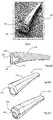
Figs. 1 to 3 . Referring toFigs. 1 to 3 animplant 1 has a distal part with aninsert 100 in astem 110, and aproximal part 120. In this case theimplant 1 is for a mammalian first carpometacarpal joint for spacing a trapezium bone of the joint from a first metacarpal bone of the joint while allowing translational and rotational movement of the first metacarpal bone in relation to the trapezium bone. Thedistal part 110 is configured for intramedullary engagement with an end of the first metacarpal bone. Theproximal part 120 has a curved saddle-shapedplatform 122 with a proximal-facing surface 124 for sliding on or traversing the trapezium bone. An articulating coupling comprises aneck 123 bridging thesaddle 122 to aball 121, as is known. This allows controlled articulation of the trapezium and first metacarpal bones. - The
insert 100 may have a buffer interface feature, in this case aflange 105 with a contoured proximally-facingsurface 101. Distally of this surface there is ashoulder 102 which acts as a key for engaging theinsert 100 in thestem 111 and preventing rotation of the insert in the stem, and surrounding asocket 103 with arim 106 to receive the articulatedcoupler ball 121. There is snap-fit engagement of the ball 121 (see especiallyFig. 2(d) ) in thesocket 103, behind the socket'srim 106, to enable the assembly of an articulating hemiarthroplasty intra-operatively, and it may also prevent disassembly of the devicein vivo. The socket can be central or offset in any direction or angle as needed. - Further distally, the
insert 100 comprises anannular locking rim 104 for snap-fitting into a corresponding groove of thestem 111recess 115 which accommodates theinsert 100. Engagement of theinsert 100 into thestem 111 is effective due to the resilience of the insert material and the fact that there is comprehensive surface-to-surface contact in a snap-fitting manner between therim 104 and its corresponding engagement surface within thestem 111. The insert is keyed by theshoulder 102 to prevent rotation and potential consequent back side wear. - Referring to
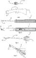
Fig. 4 there is illustrated a set of tools for use in installing an implant such as the implant ofFigs. 1 to 3 . The set of tools in this example comprises: - a primer 1 (
Figs. 5 and 6 ); - a set of five
broaches Fig. 7 ); - a first dual purpose tool 7 (
Figs. 8 and9 ); - a second dual purpose tool 8 (
Figs. 10, 11 and 12 ); - a stem insertion tool 9 (
Figs. 13(a), 13(b), 13(c) ); and - a stem exchange tool 10 (
Fig. 14 |(a), 14(b), 14(c)). - Referring to
Fig. 5 and Fig. 6 theprimer 1 has a cuttinghead 30 and facilitates the first incision into the metacarpal and eliminates the need for an awl or similar by the surgeon prior to deployment of thefirst broach 2. In addition, the geometry of the cuttinghead 30 of theprimer 1 is modelled on the geometry of the smallest broach in the tooling set,broach 2. Theprimer 1 has less bulk, is shorter, has morecutting teeth 31 per unit length and has a muchsharper point 32, but has the requisite curved volar, flat dorsal geometry of the broaches and the implant. The primer distal tip does not have a non-toothed bone marrow compacting distal end which is a feature of the broaches. In this case thehead 30 has 17 cuttingteeth 31, and in general it is preferred that there are in the range of 12 to 22, and more preferably 14 to 20 teeth. - The net effect is that the
primer 1 penetrates much farther than an awl or similar, can be used to more precisely locate the initial incision, and most significantly, reduces the effort required with thefirst broach 2. This is a particularly significant benefit for surgeons with low or reduced hand strength. - The
broaches - In addition to the tools described, a trial implant head 70 (
Fig. 22 ) may also be used during the procedure, as described in more detail below. - To install the implant, the
primer 1 is used to make the first incision into the metacarpal. By virtue of its cutting teeth density and the fact that the primer geometry closely mimics that of the smallest broach (size A, 2), the primer also aids the surgeon in creating accurate location and orientation of broaches, and hence the stem implant within the metacarpal. One or more of thebroaches stem insertion tool 9 is used to insert thestem part 110 of the implant into the metacarpal cavity until themetacarpal stem implant 110 is located flush or just proud of the resected metacarpal. This is facilitated by the close relationship of broaches to stem implants, and the surgeon being able to gauge where the base of the stem will end up in relation to the resected metacarpal based on the position of the final broach he or she uses. - Referring to
Figs. 8 and9 , the firstdual purpose tool 7 has bothrasp 52 and broach 53 features. Therasp 52 on the concave side may be used to sculpt the trapezium bone to the exact radius of theimplant head 120. The convex side of thetool 7 carries broach-like teeth 53 which may be used to remove incidental osteophytes or other protuberances encountered in the course of sculpting the trapezium. - As noted above the
head 50 of this tool has dual purpose capability. It has ashaft 51 which is tapered, or otherwise reduced in diameter for ease of access to the small joint. - The
concave side 52 of thehead 50 has rasp construction and is designed for sculpting the trapezium to the shape of the implant head. Theconvex side 53 has broach construction for removal of osteophytes and is designed to cut on the pull stroke rather than the push. - Other uses include maxillofacial surgery where bone remodeling is required but a surgeon does not want to have to remove and replace tools in succession. For example, the first
dual purpose tool 7 may be inserted into a body cavity and used for rasping function, left in situ but rotated 180 degrees, and then be used for broaching or bone remodeling functions. - The
tool 7 may be used to modify the geometry of any bone's external or internal surface depending on the geometry of the bone, the cutting surfaces, and the distal end of the tool, with the novel dual function head facilitating ease of use. - The distal end of the
tool 7 may be circular, square, flat, or toroidal in shape in accordance with the desired anatomical geometry to be produced by its use. - The distal cross-section above and below the center-line may be of one geometry on one side and another on the other side i.e. toroidal on one side and flat on the other.
- Referring to
Figs. 10, 11, and 12 , the seconddual purpose tool 8 is used as a metacarpal elevator to move tissue aside and to present the metacarpal to the surgeon for resection. It comprises astem 60 and ahead 64 with akeyhole feature 63. Thekeyhole feature 63 is at the distal end of thehead 64 of the seconddual purpose tool 8 and may be used to separate the trial head (70) from the implant stem as illustrated inFig. 12 . - This
tool 8 may for example serve as a metacarpal elevator and be used to present the metacarpal to the surgeon for resection. Theshaft 60 is flat and is angled with respect to thehandle 61 and provides optimum access to both the metacarpal and a fulcrum point location. Thehead 64 is curved to match the curvature of the metacarpal bone. - In addition, a
keyhole slot 63 at the distal end of thehead 64 matches the radius of the neck of theimplant stem 111 and can be used to lever out atrial head 70 from theliner 100 as illustrated inFig. 12 , when the surgeon is ready to fit theimplant head 120. In general, the head of thetool 8 is a claw with a variety of uses as a holder or a gripping lever for remoting an item. - Other uses for the second
dual purpose tool 8 include: a) manipulation of any small bone such as the second through fifth metacarpals during surgery; b) removal of plates in small joint surgery by using the tool to leverage the plate off the bone; c) removal of plates with screws in situ where the keyhole can sit around a nail or screw while the plate is leveraged away from the bone; d) removal of screws out of bones where the slot/keyhole 63 is used to leverage screws out of bone which may be of poor quality but where the screw has some fixation. - The internal features of a
head 40 of thestem insertion tool 9 captures both the outline and the depth of theliner flange 100 and these features permit the distal portion of the tool head to bottom out on the base of themetacarpal stem implant 111. Thedistal head 40 of thetool 9 sits on the base of thestem 111. As the surgeon manipulates thestem 111 into the bone, theliner 100 will not be damaged because the forces are transmitted from the metal head of thestem insertion tool 9 to the metal base of thestem 111, should an impactor be used in conjunction with thestem insertion tool 9. - The profile of the distal portion of the
tool head 40 exceeds that of the base of themetacarpal stem implant 111. When themetacarpal stem implant 111 has been located flush or just proud of the resected metacarpal, these design features then ensure that theliner 100 cannot be inserted below flush in the bone. - The bullnose at the distal end of the
stem insertion tool 9 is less than the internal diameter of theliner 100 at the snap fit location, and because thestem insertion tool 9 closely envelops the exterior of theliner 110, no damage occurs to the snap fit of theliner 110 with the ball of thehead 121. - If necessary, the
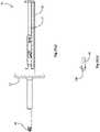
stem 110 may be removed from the metacarpal cavity using thestem exchange tool 10. If theliner 100 is removed from thestem 110, a fine metric threadedthread 45 of this tool may be engaged with the fine metric threaded thread 47 (seeFig. 13(b) ) in thestem 111, and if so desired, thestem 111 may be removed. Thestem exchange tool 10 has afull round flange 46 for impactor use to aid stem withdrawal, regardless of how deep the threads are engaged with each other. - If a
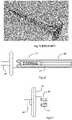
stem 111 is being implanted without apolymeric liner 100, then thestem exchange tool 10 may be used to position thestem 111 and facilitate impaction of thestem 111 into place. The same would hold true for a stem without a polymeric liner, having instead a metal socket with mating threads for thestem exchange tool 10 distal to the socket. Fig. 15 illustrates a circular indented handwheel which is at the proximal shaft ends of many prior art orthopaedic broaches. The prior art circular proximal shaft ends (used with impactors for tool removal) are gripped by the surgeon and can promote twisting of the tooling which can lead to larger apertures in the bone than intended. The aperture created by a broach cutting head should correspond to the geometry of the implant. Prior art broaches with the circular type of handles are twisted to gain purchase in the bone.- In the tool set, the tools have plain elongate
proximal handles 20 which are fluted 21 to aid grip as illustrated inFigs. 16 and 17 . The tooling therefore promotes axial motion, and this leads to aperture creation in the bone which conforms more exactly to the geometry of the broach cutting head and thus the implant. - The
primer 1, thebroaches stem exchange tool 10 all haveflanges handle 20 as illustrated inFigs. 16 to 18 . The flanges 25 (and 46 on the tool 10) enable an impactor to be used, if required, for tool extraction purposes. They also serve as a stop for the surgeon's hand and, coupled with the flat on the handle which carries thetool identification 26 and serves as a thumb grip, theprimer 1 and broaches 2, 3, 4, 5, 6 promote firm axial forward motion. - This means that, in contrast to other tooling, the tooling of the invention requires little or no impacting. This reduces potential fracture damage of the bone during surgery which has been observed in clinical practice with conventional tools.
- The
flanges 25 of theprimer 1 and allbroaches non-circumferential side edge 27 on the volar aspect at 270° as illustrated inFig. 18 . - This facilitates the surgeon, by enabling the tools to be used at an angle very much in line with the axis of the metacarpal during surgery. This feature also further reduces any tendency for the surgeon to twist the tool, and it also permits ample space on the distal side of the flange for an impactor to aid withdrawal of the tool, should that be required.
- An alternative
stem insertion tool 90 incorporates aball 91 where the diameter is less than that of the implant head ball diameter, but is just sufficient to provide a light snap-fit. This light snap-fit provides attachment between thetool 90 and the implant stem-liner assembly 110, such that the surgeon may use the tool to transport the implant from the preparation area directly to the implant site. - The tool set may additionally include a
tool 95 to withdraw aliner 100 which has been assembled in astem 111, which in turn has been implanted in a metacarpal. There may be occasion to withdraw a liner when access to the threadedportion 47 of the stem is required in order to withdraw or exchange the stem. A threadedhead 96 of thetool 95 is configured as a double-start tapered thread where the helices of the thread engage with the snap-fit diameter of the socket within theliner 100. Thetool 95 is threaded into theliner 100 until resistance is felt at which point theliner 100 is readily levered out of the stem housing 112 (illustrated inFig. 20(a) ). - The
trial head 70 conforms to the geometries of the associatedimplant head 120, except for having two throughholes 71 through the saddle, and having two letter identifications appropriate to each of the four trial head types laser etched onto the base. The through holes 71 aid in differentiating the trial heads 70 from the implant'scomponents 120. - The ball diameter of the
trial head 70 is also slightly smaller than the ball diameter of theimplant head 120, so that the snap-fit of theliner 100 is not stressed. Although the ball diameter is slightly reduced, the metacarpal to trapezium distraction distance is maintained the same as that of the implant heads 120, by increasing the neck lengths of the trial heads 70. - The use of trial heads 70 in conjunction with the
implant stem 111 decreases the number of surgical steps to be successfully completed by the end user. It avoids need for the surgeon to open and use an implant on a trial-and-error bases, by using thetrial head 70 to check size firstly before choosing the implant to use. - The instrument tray is advantageous in that, rather than containing multiple stand-offs to house
individual tools 85, all the tools are located by twostrips tool 85 is shown) are further secured by asingle strip 86 attached to the underside of alid 87, which acts on the thumb grip flats of the handles of the tools. Correct orientation of the lid 87 (and thus the securing strip 86) is ensured by locating two latches closer together on one side of the lid than the other (not shown). - An
assembly fixture 140 may be used in a surgical setting to assemble aliner 100 into astem 111. Abase 141 of thefixture 140 hasseparate retainers 142 for each of the implant stem sizes. Eachretainer 142 has asocket 143 for cradling the distal (narrow) end of thestem 111 to retain it in an upright position. Theretainers 141 also have aligned upper through holes for retaining the wider (proximal) ends of the stems 111. Each retainer is sized in increasing size order from left to right for a particular stem size, called Stem A, B, C, D, and E respectively. - The assembly also comprises a
pusher 148 with aknurled thumbwheel 149 for rotating ascrew 150 with alower pusher face 151. Thescrew 150 extends through a pusher body with a pair of parallel dovetails 152 for engaging in correspondingdovetail grooves 145. - A
stem 111 is placed vertically in theappropriate retainer 141, aliner 100 is aligned with the universal cap formed by thebody 152 of thepusher 148, incorporating a light snap fit as it is fitted to the liner. Thepusher 148, when pushed fully home in any one of the sets ofslots 145, is positioned such that the centre of thescrew 150 is centered over the stem. Thescrew 150 is then turned to fully push theliner 100 into thestem 111, thereby seating theliner 100 in thestem 111. - The following is a listing of all components of a full tool-set apparatus in one example.
1 Primer 2 Broach A 3 Broach B 4 Broach C 5 Broach D 6 Broach E 7 Rasp 8 Metacarpal Elevator 9 Stem Insertion Tool 10 Stem Exchange Tool 95 Liner Exchange Tool 70 Trial Head: Short Neck, Regular 70 Trial Head: Short Neck, Flat 70 Trial Head: Long Neck, Regular 70 Trial Head: Long Neck, Flat 140 Intra Operative Assembly 141 Fixture Base 148 Slider 149/150 Press Screw 152 Liner Cap 80 Assembled Tray 80 Empty Tray - It will be appreciated that the apparatus described provides major assistance to a surgeon for performing an operation, both in terms of accuracy and reduced time.
- The invention is not limited to the embodiments hereinbefore described, which may be varied in construction and detail within the scope of the claims.
Claims (17)
- A set of tools for installation of a stem implant into a bone, comprising:a plurality of stem-shaped broaches (2-6) of different size, each of the broaches having a distal head and a plurality of cutting teeth along a length thereof,a stem-shaped priming tool (1) having a distal head (30) and a plurality of cutting teeth (31) along a length thereof;characterized in that,the priming tool is shorter than, has more cutting teeth per unit length, and has a sharper distal tip than the smallest broach; andthe set of tools further comprises a stem insertion tool (9) having implant stem engagement features (40) for engaging with corresponding engagement features of an implant stem (100, 111) for transmission of forces applied to the stem insertion tool to the stem implant, and wherein said engagement features comprise:a bull nose feature (40), ora ball (91) configured for snap-fitting into an implant, such as an implant liner (100) of a stem (111).
- A set of tools as claimed in claim 1, wherein the priming tool and the broaches each comprises a proximal handle (20) having flutes (21) to aid grip, and a flange (25) distal of the proximal handle, and optionally the flange (25) is truncated (27) on one side of the handle.
- A set of tools as claimed in either of claims 1 or 2, wherein distal heads (30) of the priming tool (1) and of the broaches (2-6) are each curved in a volar direction and are substantially flat in a dorsal direction.
- A set of tools as claimed in any of claims 1 to 3, further comprising a first dual-purpose tool (7)
comprising a head which provides both a rasp (52) and a broach (53), the head having a first side and a second side opposite to the first side, the first side having a concave shape and comprising rasp features and the second side having a convex shape and comprising broach features. - A set of tools as claimed in any preceding claim, further comprising a second dual-purpose tool (8) comprising a stem (60) and a head (64) in the shape of a claw for elevation of a bone and said head (64) further comprises a distal engagement slot (63).
- A set of tools as claimed in any preceding claim, further comprising a stem exchange tool (10) comprising a threaded thread (45) for engagement with a threaded socket (47) of an implant stem.
- A set of tools as claimed in any preceding claim, including a liner removal tool (95) to withdraw a liner (100) which has been assembled in a stem (111), which in turn has been implanted in a metacarpal, said tool comprising a threaded head (96) configured to engage a liner by tool rotation.
- A set of tools as claimed in any of claims 1 to 7, further comprising at least one trial head (70) for temporary placement in or on a bone or implant part during preparation of the bone to receive an implant head, wherein the trial head (70) has some dimensions that are smaller than those of an implant head, and optionally the set of tools further comprises a dual purpose tool comprising a stem (60) and a head (64) in the shape of a claw for elevation of bone and the head has a slot (63) configured to separate the trial head from an implant stem.
- A set of tools as claimed in claim 8, wherein said trial head comprises a ball for insertion in an implant socket on a trial basis, and said ball is smaller than an implant ball for said socket, and optionally said trial head comprises at least one aperture (71) which is not functional but identifies the trial head as a such.
- A set of tools as claimed in any of claims 1 to 9 further comprising an implant comprising a stem-liner assembly (110) to provide a kit.
- A set of tools as claimed in claim 10, wherein the stem (111) is configured for intramedullary engagement with an end of the first metacarpal bone, and the implant comprises a liner (100) for a proximal end of the stem.
- A set of tools as claimed in either of claims 10 or 11, wherein the implant (120, 100, 110) is for a first carpometacarpal joint for spacing a trapezium bone from a first metacarpal bone, the implant comprising a head (120) having a saddle-shaped surface (122) for translational movement over the trapezium and the stem-liner assembly (110) is mountable to the head in an articulated coupling (121, 103) such as a ball and socket joint, and wherein the head (120) comprises a ball of the head (121) for mounting to the stem.
- A set of tools as claimed in any of claims 1 to 9 and a tray (80) to house the tools, wherein the tray comprises a base, side walls upstanding from the base, and tool support strips (81, 82) mounted to the base, wherein the tools are mounted to the strips in the order in which the tools are to be used in a surgical procedure.
- A set of tools as claimed in claim 13, comprising a lid (87) for the tray, the lid having a strip (86) projecting inwardly therefrom to engage the tools and retain their position in the tray, wherein the lid strip (86) is configured to engage flats of tool handles for a correct closing of the lid and tools.
- A set of tools as claimed in any preceding claim further comprising an assembly fixture (140) to assemble a liner (100) into an implant stem (111), the fixture comprising a plurality of stem retainers (142) for each of a plurality of the implant stem sizes, and a pusher device (148) arranged to push a liner (100) into a stem (111) upon rotation of a handle (147).
- A set of tools as claimed in claim 15, wherein each retainer (142) has a socket (143) for cradling a distal end of a stem (111) and an aligned through hole (144) to retain it in a liner (100) insertion position.
- A set of tools as claimed in either of claims 15 or 16, wherein the pusher device (148) comprises a screw (150) with a pusher face (151) extending through a pusher body, and wherein the pusher body comprises a pair of parallel dovetails (152) for engaging in corresponding dovetail grooves (145) for positioning the pusher screw in alignment with a stem in the retainer.
Priority Applications (1)
| Application Number | Priority Date | Filing Date | Title |
|---|---|---|---|
| EP22191814.7AEP4111989B1 (en) | 2019-05-14 | 2020-04-24 | A set of tools for installing an implant |
Applications Claiming Priority (2)
| Application Number | Priority Date | Filing Date | Title |
|---|---|---|---|
| US201962847689P | 2019-05-14 | 2019-05-14 | |
| PCT/EP2020/061558WO2020229143A2 (en) | 2019-05-14 | 2020-04-24 | A set of tools for installing an implant |
Related Child Applications (2)
| Application Number | Title | Priority Date | Filing Date |
|---|---|---|---|
| EP22191814.7ADivision-IntoEP4111989B1 (en) | 2019-05-14 | 2020-04-24 | A set of tools for installing an implant |
| EP22191814.7ADivisionEP4111989B1 (en) | 2019-05-14 | 2020-04-24 | A set of tools for installing an implant |
Publications (2)
| Publication Number | Publication Date |
|---|---|
| EP3914166A2 EP3914166A2 (en) | 2021-12-01 |
| EP3914166B1true EP3914166B1 (en) | 2022-10-05 |
Family
ID=70471035
Family Applications (2)
| Application Number | Title | Priority Date | Filing Date |
|---|---|---|---|
| EP22191814.7AActiveEP4111989B1 (en) | 2019-05-14 | 2020-04-24 | A set of tools for installing an implant |
| EP20722294.4AActiveEP3914166B1 (en) | 2019-05-14 | 2020-04-24 | A set of tools for installing an implant |
Family Applications Before (1)
| Application Number | Title | Priority Date | Filing Date |
|---|---|---|---|
| EP22191814.7AActiveEP4111989B1 (en) | 2019-05-14 | 2020-04-24 | A set of tools for installing an implant |
Country Status (8)
| Country | Link |
|---|---|
| US (3) | US12161566B2 (en) |
| EP (2) | EP4111989B1 (en) |
| JP (1) | JP7270063B2 (en) |
| CN (1) | CN113645925B (en) |
| AU (1) | AU2020276042B2 (en) |
| CA (1) | CA3132788C (en) |
| DK (1) | DK3914166T3 (en) |
| WO (1) | WO2020229143A2 (en) |
Cited By (1)
| Publication number | Priority date | Publication date | Assignee | Title |
|---|---|---|---|---|
| EP4552616A1 (en)* | 2023-11-09 | 2025-05-14 | LOCI Orthopaedics Limited | A surgical broaching tool |
Families Citing this family (8)
| Publication number | Priority date | Publication date | Assignee | Title |
|---|---|---|---|---|
| BE1027082B1 (en)* | 2019-02-27 | 2020-09-21 | Zimmer Inc | Tool for clearing a carpal bone |
| JP7270063B2 (en)* | 2019-05-14 | 2023-05-09 | ローサイ・オーソペディックス・リミテッド | A set of tools for introducing implants |
| US11992412B2 (en)* | 2020-03-18 | 2024-05-28 | In2Bones Usa, Llc | Radial head fracture treatment system |
| US11642226B2 (en)* | 2020-05-01 | 2023-05-09 | Ensemble Orthopedics, Inc. | Implantable interpositional orthopedic pain management |
| US12290443B2 (en) | 2020-05-01 | 2025-05-06 | Ensemble Orthopedics, Inc. | Implantable interpositional orthopedic pain management |
| WO2024041771A1 (en) | 2022-08-23 | 2024-02-29 | Loci Orthopaedics Limited | Bone joint implant especially suitable for a carpometacarpal (cmc) joint |
| WO2024200544A1 (en)* | 2023-03-31 | 2024-10-03 | Loci Orthopaedics Limited | A distraction spacer for a joint implant |
| US20250152186A1 (en)* | 2023-11-09 | 2025-05-15 | Loci Orthopaedics Limited | Broaching tool |
Family Cites Families (54)
| Publication number | Priority date | Publication date | Assignee | Title |
|---|---|---|---|---|
| DE7146205U (en)* | 1971-12-08 | 1972-03-16 | Aesculap Werke Ag | Bone lever |
| US4995875A (en) | 1988-05-27 | 1991-02-26 | Cecil Coes | Femoral elevating tool |
| US5324293A (en) | 1992-11-13 | 1994-06-28 | U.S. Medical Products, Inc. | Surgical broach and broach holder |
| US5702470A (en)* | 1996-02-23 | 1997-12-30 | Kinetikos Medical Incorporated | Prosthetic wrist implant and related method of implantation |
| US6206884B1 (en)* | 1998-07-15 | 2001-03-27 | Medidea, Llc | Reduction-based joint replacement apparatus and methods |
| US6270529B1 (en)* | 1999-09-01 | 2001-08-07 | Wright Medical Technology, Inc. | Modular implant for replacing end of radius and having drainage passage for trapped fluid |
| WO2001028469A2 (en) | 1999-10-21 | 2001-04-26 | Sdgi Holdings, Inc. | Devices and techniques for a posterior lateral disc space approach |
| AU769391C (en)* | 1999-10-21 | 2008-01-17 | Warsaw Orthopedic, Inc. | Devices and techniques for a posterior lateral disc space approach |
| US20020016634A1 (en)* | 2000-07-28 | 2002-02-07 | Brian Maroney | Device and method for positioning an eccentric humeral head of a humerus prothesis for a shoulder arthroplasty |
| US6355045B1 (en)* | 2000-12-28 | 2002-03-12 | Depuy Orthopaedics, Inc. | Method and apparatus for surgically preparing a tibia for implantation of a prosthetic implant component which has an offset stem |
| ES2254574T3 (en) | 2002-08-30 | 2006-06-16 | Zimmer Gmbh | OPERATING SYSTEM. |
| US6656187B1 (en)* | 2002-09-03 | 2003-12-02 | Depuy Products, Inc. | Adjustable orthopaedic instrument |
| US7074224B2 (en)* | 2003-06-25 | 2006-07-11 | Depuy Products, Inc. | Modular tapered reamer for bone preparation and associated method |
| US8657824B2 (en)* | 2003-11-18 | 2014-02-25 | Smith & Nephew, Inc. | Universal double offset surgical instrument |
| US7588590B2 (en)* | 2003-12-10 | 2009-09-15 | Facet Solutions, Inc | Spinal facet implant with spherical implant apposition surface and bone bed and methods of use |
| US7833228B1 (en)* | 2004-01-05 | 2010-11-16 | Biomet Manufacturing Corp. | Method and instrumentation for performing minimally invasive hip arthroplasty |
| US9451990B2 (en)* | 2004-02-17 | 2016-09-27 | Globus Medical, Inc. | Facet joint replacement instruments and methods |
| US7632273B2 (en)* | 2004-06-29 | 2009-12-15 | Depuy Products, Inc. | Minimally invasive bone broach |
| US7854768B2 (en) | 2006-01-20 | 2010-12-21 | Zimmer Technology, Inc. | Shoulder arthroplasty system |
| US7935125B2 (en)* | 2006-03-06 | 2011-05-03 | Howmedica Osteonics Corp. | Compound offset handle |
| US8579985B2 (en)* | 2006-12-07 | 2013-11-12 | Ihip Surgical, Llc | Method and apparatus for hip replacement |
| US7875082B2 (en) | 2008-05-09 | 2011-01-25 | Remi Sciences, Inc. | Ulnar head prosthesis system |
| US8870875B2 (en) | 2008-07-25 | 2014-10-28 | Zimmer Gmbh | Gender specific femoral rasps |
| US9241798B2 (en)* | 2009-03-20 | 2016-01-26 | David A. Petersen | Surgical methods and tools |
| US20110015634A1 (en) | 2009-07-14 | 2011-01-20 | Biomet Manufacturing Corp. | Modular Reaming System for Femoral Revision |
| US9381045B2 (en)* | 2010-01-13 | 2016-07-05 | Jcbd, Llc | Sacroiliac joint implant and sacroiliac joint instrument for fusing a sacroiliac joint |
| US20140194999A1 (en) | 2010-05-24 | 2014-07-10 | Skeletal Dynamics Llc | Devices, implements and methods for the treatment of a multi-axis joint |
| US9072564B2 (en)* | 2010-06-02 | 2015-07-07 | Wright Medical Technology, Inc. | Hammer toe implant and method |
| AU2011302221A1 (en)* | 2010-09-14 | 2013-03-07 | Imds Llc | Reciprocating surgical instrument |
| ES2635496T3 (en) | 2011-04-06 | 2017-10-04 | Depuy Synthes Products Llc | Modular Orthopedic Hip Prosthesis |
| US20120265319A1 (en)* | 2011-04-13 | 2012-10-18 | Total Joint Orthopedics | Total hip arthroplasty |
| EP2514372A1 (en)* | 2011-04-21 | 2012-10-24 | Deru GmbH | Set of instruments for inserting a joint prosthetic, in particular knee prosthetic |
| US9113915B2 (en)* | 2012-05-30 | 2015-08-25 | Depuy (Ireland) | Method of surgically preparing a patient's tibia |
| US9456828B2 (en)* | 2013-01-18 | 2016-10-04 | Symmetry Medical Manufacturing, Inc. | Medical instrument handle |
| DE102013101651A1 (en)* | 2013-02-20 | 2014-09-04 | Karl Storz Gmbh & Co. Kg | Endoscopic instrument and shaft for an endoscopic instrument |
| USD730522S1 (en)* | 2013-03-11 | 2015-05-26 | Catalyst Orthopaedics Llc | Implant |
| US9113918B2 (en)* | 2013-03-15 | 2015-08-25 | Depuy (Ireland) | Femoral surgical instrument and method of using same |
| US11172939B2 (en)* | 2013-03-15 | 2021-11-16 | Jcbd, Llc | Systems for and methods of preparing a sacroiliac joint for fusion |
| US9826986B2 (en)* | 2013-07-30 | 2017-11-28 | Jcbd, Llc | Systems for and methods of preparing a sacroiliac joint for fusion |
| US10166031B2 (en)* | 2013-10-29 | 2019-01-01 | Biomet Manufacturing, Llc | Method and apparatus for preparing an implantation site |
| US9474561B2 (en)* | 2013-11-19 | 2016-10-25 | Wright Medical Technology, Inc. | Two-wire technique for installing hammertoe implant |
| US10258484B2 (en)* | 2014-06-12 | 2019-04-16 | Limacorporate S.P.A. | Instrument for the removal of a bone insert and corresponding method |
| JP6246083B2 (en)* | 2014-06-30 | 2017-12-13 | 京セラ株式会社 | Surgical unit for joint replacement |
| JP6407619B2 (en)* | 2014-08-11 | 2018-10-17 | 京セラ株式会社 | Grip and shell positioner for prosthetic surgical instruments |
| US10245149B2 (en)* | 2015-08-03 | 2019-04-02 | Nicholas John Loffredo | Reverse total hip replacement |
| EP3337429B1 (en)* | 2015-08-21 | 2023-02-15 | HIP Innovation Technology, LLC | Surgical trays and instruments for implanting a hip replacement prosthesis |
| EP3135254B1 (en)* | 2015-08-26 | 2019-01-02 | Biedermann Technologies GmbH & Co. KG | Intervertebral implant and device for inserting an intervertebral implant |
| CA3100061A1 (en) | 2015-09-02 | 2017-03-09 | Wright Medical Technology, Inc. | Chevron osteotomy tools and methods |
| EP3205311A1 (en) | 2016-02-10 | 2017-08-16 | National University of Ireland, Galway | An implant for a bone joint |
| US10729550B2 (en)* | 2016-07-28 | 2020-08-04 | Corentec Co., Ltd | Dual mobility acetabular cup assembly for artificial hip joint |
| AU2018243709A1 (en)* | 2017-03-29 | 2019-10-03 | Depuy Ireland Unlimited Company | Guided osteotome |
| US20190099191A1 (en) | 2017-09-29 | 2019-04-04 | DePuy Synthes Products, Inc. | Distally reaming broach |
| US10478262B2 (en)* | 2017-12-04 | 2019-11-19 | Depuy Ireland Unlimited Company | Orthopaedic instrument system including an instrument caddy and method for assembling a surgical instrument |
| JP7270063B2 (en)* | 2019-05-14 | 2023-05-09 | ローサイ・オーソペディックス・リミテッド | A set of tools for introducing implants |
- 2020
- 2020-04-24JPJP2021560158Apatent/JP7270063B2/enactiveActive
- 2020-04-24CACA3132788Apatent/CA3132788C/enactiveActive
- 2020-04-24WOPCT/EP2020/061558patent/WO2020229143A2/ennot_activeCeased
- 2020-04-24AUAU2020276042Apatent/AU2020276042B2/enactiveActive
- 2020-04-24EPEP22191814.7Apatent/EP4111989B1/enactiveActive
- 2020-04-24USUS17/604,300patent/US12161566B2/enactiveActive
- 2020-04-24CNCN202080023992.3Apatent/CN113645925B/enactiveActive
- 2020-04-24EPEP20722294.4Apatent/EP3914166B1/enactiveActive
- 2020-04-24DKDK20722294.4Tpatent/DK3914166T3/enactive
- 2022
- 2022-06-06USUS17/833,246patent/US11612500B2/enactiveActive
- 2024
- 2024-11-06USUS18/938,779patent/US20250134677A1/enactivePending
Cited By (1)
| Publication number | Priority date | Publication date | Assignee | Title |
|---|---|---|---|---|
| EP4552616A1 (en)* | 2023-11-09 | 2025-05-14 | LOCI Orthopaedics Limited | A surgical broaching tool |
Also Published As
| Publication number | Publication date |
|---|---|
| JP2022540539A (en) | 2022-09-16 |
| WO2020229143A3 (en) | 2020-12-24 |
| DK3914166T3 (en) | 2023-01-09 |
| WO2020229143A2 (en) | 2020-11-19 |
| US12161566B2 (en) | 2024-12-10 |
| EP3914166A2 (en) | 2021-12-01 |
| US20220202592A1 (en) | 2022-06-30 |
| JP7270063B2 (en) | 2023-05-09 |
| EP4111989B1 (en) | 2025-07-02 |
| EP4111989A1 (en) | 2023-01-04 |
| US20220296389A1 (en) | 2022-09-22 |
| AU2020276042B2 (en) | 2023-07-13 |
| US20250134677A1 (en) | 2025-05-01 |
| CN113645925B (en) | 2025-08-01 |
| EP4111989C0 (en) | 2025-07-02 |
| AU2020276042A1 (en) | 2021-09-16 |
| CA3132788A1 (en) | 2020-11-19 |
| US11612500B2 (en) | 2023-03-28 |
| CN113645925A (en) | 2021-11-12 |
| CA3132788C (en) | 2024-06-11 |
Similar Documents
| Publication | Publication Date | Title |
|---|---|---|
| EP3914166B1 (en) | A set of tools for installing an implant | |
| US20250281300A1 (en) | Convertible stem/fracture stem | |
| US11612501B2 (en) | Hip and knee joint stem explant system and methods of using the same | |
| US7608110B2 (en) | Systems for bone replacement | |
| EP2340787B1 (en) | Reciprocating rasp surgical instrument | |
| AU2023202032B2 (en) | Surgical trays, instruments and methods for implanting a hip replacement prosthesis | |
| EP2340773A1 (en) | Reciprocating rasp surgical instrument | |
| US20210353432A1 (en) | Prosthetic implant removal tool and tool set | |
| AU2003204784A1 (en) | Prosthesis removal cutting guide, cutting tool and method | |
| EP4093339A1 (en) | Prosthetic implant removal tool and tool set | |
| CN110709034A (en) | Radius head implant | |
| US20250073046A1 (en) | Systems and methods for total ankle arthroplasty |
Legal Events
| Date | Code | Title | Description |
|---|---|---|---|
| STAA | Information on the status of an ep patent application or granted ep patent | Free format text:STATUS: UNKNOWN | |
| STAA | Information on the status of an ep patent application or granted ep patent | Free format text:STATUS: THE INTERNATIONAL PUBLICATION HAS BEEN MADE | |
| PUAI | Public reference made under article 153(3) epc to a published international application that has entered the european phase | Free format text:ORIGINAL CODE: 0009012 | |
| STAA | Information on the status of an ep patent application or granted ep patent | Free format text:STATUS: REQUEST FOR EXAMINATION WAS MADE | |
| 17P | Request for examination filed | Effective date:20210822 | |
| AK | Designated contracting states | Kind code of ref document:A2 Designated state(s):AL AT BE BG CH CY CZ DE DK EE ES FI FR GB GR HR HU IE IS IT LI LT LU LV MC MK MT NL NO PL PT RO RS SE SI SK SM TR | |
| GRAP | Despatch of communication of intention to grant a patent | Free format text:ORIGINAL CODE: EPIDOSNIGR1 | |
| STAA | Information on the status of an ep patent application or granted ep patent | Free format text:STATUS: GRANT OF PATENT IS INTENDED | |
| DAV | Request for validation of the european patent (deleted) | ||
| DAX | Request for extension of the european patent (deleted) | ||
| GRAS | Grant fee paid | Free format text:ORIGINAL CODE: EPIDOSNIGR3 | |
| INTG | Intention to grant announced | Effective date:20220802 | |
| GRAA | (expected) grant | Free format text:ORIGINAL CODE: 0009210 | |
| STAA | Information on the status of an ep patent application or granted ep patent | Free format text:STATUS: THE PATENT HAS BEEN GRANTED | |
| AK | Designated contracting states | Kind code of ref document:B1 Designated state(s):AL AT BE BG CH CY CZ DE DK EE ES FI FR GB GR HR HU IE IS IT LI LT LU LV MC MK MT NL NO PL PT RO RS SE SI SK SM TR | |
| REG | Reference to a national code | Ref country code:GB Ref legal event code:FG4D | |
| REG | Reference to a national code | Ref country code:CH Ref legal event code:EP | |
| REG | Reference to a national code | Ref country code:AT Ref legal event code:REF Ref document number:1522251 Country of ref document:AT Kind code of ref document:T Effective date:20221015 | |
| REG | Reference to a national code | Ref country code:IE Ref legal event code:FG4D | |
| REG | Reference to a national code | Ref country code:DE Ref legal event code:R096 Ref document number:602020005497 Country of ref document:DE | |
| REG | Reference to a national code | Ref country code:NL Ref legal event code:FP | |
| REG | Reference to a national code | Ref country code:DK Ref legal event code:T3 Effective date:20230103 | |
| REG | Reference to a national code | Ref country code:LT Ref legal event code:MG9D | |
| REG | Reference to a national code | Ref country code:AT Ref legal event code:MK05 Ref document number:1522251 Country of ref document:AT Kind code of ref document:T Effective date:20221005 | |
| PG25 | Lapsed in a contracting state [announced via postgrant information from national office to epo] | Ref country code:SE Free format text:LAPSE BECAUSE OF FAILURE TO SUBMIT A TRANSLATION OF THE DESCRIPTION OR TO PAY THE FEE WITHIN THE PRESCRIBED TIME-LIMIT Effective date:20221005 Ref country code:PT Free format text:LAPSE BECAUSE OF FAILURE TO SUBMIT A TRANSLATION OF THE DESCRIPTION OR TO PAY THE FEE WITHIN THE PRESCRIBED TIME-LIMIT Effective date:20230206 Ref country code:NO Free format text:LAPSE BECAUSE OF FAILURE TO SUBMIT A TRANSLATION OF THE DESCRIPTION OR TO PAY THE FEE WITHIN THE PRESCRIBED TIME-LIMIT Effective date:20230105 Ref country code:LT Free format text:LAPSE BECAUSE OF FAILURE TO SUBMIT A TRANSLATION OF THE DESCRIPTION OR TO PAY THE FEE WITHIN THE PRESCRIBED TIME-LIMIT Effective date:20221005 Ref country code:FI Free format text:LAPSE BECAUSE OF FAILURE TO SUBMIT A TRANSLATION OF THE DESCRIPTION OR TO PAY THE FEE WITHIN THE PRESCRIBED TIME-LIMIT Effective date:20221005 Ref country code:ES Free format text:LAPSE BECAUSE OF FAILURE TO SUBMIT A TRANSLATION OF THE DESCRIPTION OR TO PAY THE FEE WITHIN THE PRESCRIBED TIME-LIMIT Effective date:20221005 Ref country code:AT Free format text:LAPSE BECAUSE OF FAILURE TO SUBMIT A TRANSLATION OF THE DESCRIPTION OR TO PAY THE FEE WITHIN THE PRESCRIBED TIME-LIMIT Effective date:20221005 | |
| PG25 | Lapsed in a contracting state [announced via postgrant information from national office to epo] | Ref country code:RS Free format text:LAPSE BECAUSE OF FAILURE TO SUBMIT A TRANSLATION OF THE DESCRIPTION OR TO PAY THE FEE WITHIN THE PRESCRIBED TIME-LIMIT Effective date:20221005 Ref country code:PL Free format text:LAPSE BECAUSE OF FAILURE TO SUBMIT A TRANSLATION OF THE DESCRIPTION OR TO PAY THE FEE WITHIN THE PRESCRIBED TIME-LIMIT Effective date:20221005 Ref country code:LV Free format text:LAPSE BECAUSE OF FAILURE TO SUBMIT A TRANSLATION OF THE DESCRIPTION OR TO PAY THE FEE WITHIN THE PRESCRIBED TIME-LIMIT Effective date:20221005 Ref country code:IS Free format text:LAPSE BECAUSE OF FAILURE TO SUBMIT A TRANSLATION OF THE DESCRIPTION OR TO PAY THE FEE WITHIN THE PRESCRIBED TIME-LIMIT Effective date:20230205 Ref country code:HR Free format text:LAPSE BECAUSE OF FAILURE TO SUBMIT A TRANSLATION OF THE DESCRIPTION OR TO PAY THE FEE WITHIN THE PRESCRIBED TIME-LIMIT Effective date:20221005 Ref country code:GR Free format text:LAPSE BECAUSE OF FAILURE TO SUBMIT A TRANSLATION OF THE DESCRIPTION OR TO PAY THE FEE WITHIN THE PRESCRIBED TIME-LIMIT Effective date:20230106 | |
| P01 | Opt-out of the competence of the unified patent court (upc) registered | Effective date:20230413 | |
| REG | Reference to a national code | Ref country code:DE Ref legal event code:R097 Ref document number:602020005497 Country of ref document:DE | |
| PG25 | Lapsed in a contracting state [announced via postgrant information from national office to epo] | Ref country code:SM Free format text:LAPSE BECAUSE OF FAILURE TO SUBMIT A TRANSLATION OF THE DESCRIPTION OR TO PAY THE FEE WITHIN THE PRESCRIBED TIME-LIMIT Effective date:20221005 Ref country code:RO Free format text:LAPSE BECAUSE OF FAILURE TO SUBMIT A TRANSLATION OF THE DESCRIPTION OR TO PAY THE FEE WITHIN THE PRESCRIBED TIME-LIMIT Effective date:20221005 Ref country code:EE Free format text:LAPSE BECAUSE OF FAILURE TO SUBMIT A TRANSLATION OF THE DESCRIPTION OR TO PAY THE FEE WITHIN THE PRESCRIBED TIME-LIMIT Effective date:20221005 Ref country code:CZ Free format text:LAPSE BECAUSE OF FAILURE TO SUBMIT A TRANSLATION OF THE DESCRIPTION OR TO PAY THE FEE WITHIN THE PRESCRIBED TIME-LIMIT Effective date:20221005 | |
| PLBE | No opposition filed within time limit | Free format text:ORIGINAL CODE: 0009261 | |
| STAA | Information on the status of an ep patent application or granted ep patent | Free format text:STATUS: NO OPPOSITION FILED WITHIN TIME LIMIT | |
| PG25 | Lapsed in a contracting state [announced via postgrant information from national office to epo] | Ref country code:SK Free format text:LAPSE BECAUSE OF FAILURE TO SUBMIT A TRANSLATION OF THE DESCRIPTION OR TO PAY THE FEE WITHIN THE PRESCRIBED TIME-LIMIT Effective date:20221005 Ref country code:AL Free format text:LAPSE BECAUSE OF FAILURE TO SUBMIT A TRANSLATION OF THE DESCRIPTION OR TO PAY THE FEE WITHIN THE PRESCRIBED TIME-LIMIT Effective date:20221005 | |
| 26N | No opposition filed | Effective date:20230706 | |
| PG25 | Lapsed in a contracting state [announced via postgrant information from national office to epo] | Ref country code:SI Free format text:LAPSE BECAUSE OF FAILURE TO SUBMIT A TRANSLATION OF THE DESCRIPTION OR TO PAY THE FEE WITHIN THE PRESCRIBED TIME-LIMIT Effective date:20221005 | |
| PG25 | Lapsed in a contracting state [announced via postgrant information from national office to epo] | Ref country code:LU Free format text:LAPSE BECAUSE OF NON-PAYMENT OF DUE FEES Effective date:20230424 | |
| PG25 | Lapsed in a contracting state [announced via postgrant information from national office to epo] | Ref country code:MC Free format text:LAPSE BECAUSE OF FAILURE TO SUBMIT A TRANSLATION OF THE DESCRIPTION OR TO PAY THE FEE WITHIN THE PRESCRIBED TIME-LIMIT Effective date:20221005 | |
| PG25 | Lapsed in a contracting state [announced via postgrant information from national office to epo] | Ref country code:MC Free format text:LAPSE BECAUSE OF FAILURE TO SUBMIT A TRANSLATION OF THE DESCRIPTION OR TO PAY THE FEE WITHIN THE PRESCRIBED TIME-LIMIT Effective date:20221005 | |
| PG25 | Lapsed in a contracting state [announced via postgrant information from national office to epo] | Ref country code:BG Free format text:LAPSE BECAUSE OF FAILURE TO SUBMIT A TRANSLATION OF THE DESCRIPTION OR TO PAY THE FEE WITHIN THE PRESCRIBED TIME-LIMIT Effective date:20221005 | |
| PG25 | Lapsed in a contracting state [announced via postgrant information from national office to epo] | Ref country code:BG Free format text:LAPSE BECAUSE OF FAILURE TO SUBMIT A TRANSLATION OF THE DESCRIPTION OR TO PAY THE FEE WITHIN THE PRESCRIBED TIME-LIMIT Effective date:20221005 | |
| PGFP | Annual fee paid to national office [announced via postgrant information from national office to epo] | Ref country code:IE Payment date:20250306 Year of fee payment:6 | |
| PGFP | Annual fee paid to national office [announced via postgrant information from national office to epo] | Ref country code:FR Payment date:20250327 Year of fee payment:6 | |
| PGFP | Annual fee paid to national office [announced via postgrant information from national office to epo] | Ref country code:IT Payment date:20250306 Year of fee payment:6 Ref country code:GB Payment date:20250303 Year of fee payment:6 | |
| PGFP | Annual fee paid to national office [announced via postgrant information from national office to epo] | Ref country code:NL Payment date:20250423 Year of fee payment:6 | |
| PGFP | Annual fee paid to national office [announced via postgrant information from national office to epo] | Ref country code:DE Payment date:20250331 Year of fee payment:6 | |
| PGFP | Annual fee paid to national office [announced via postgrant information from national office to epo] | Ref country code:DK Payment date:20250422 Year of fee payment:6 | |
| PGFP | Annual fee paid to national office [announced via postgrant information from national office to epo] | Ref country code:BE Payment date:20250428 Year of fee payment:6 | |
| PGFP | Annual fee paid to national office [announced via postgrant information from national office to epo] | Ref country code:CH Payment date:20250501 Year of fee payment:6 | |
| PG25 | Lapsed in a contracting state [announced via postgrant information from national office to epo] | Ref country code:CY Free format text:LAPSE BECAUSE OF FAILURE TO SUBMIT A TRANSLATION OF THE DESCRIPTION OR TO PAY THE FEE WITHIN THE PRESCRIBED TIME-LIMIT; INVALID AB INITIO Effective date:20200424 | |
| PG25 | Lapsed in a contracting state [announced via postgrant information from national office to epo] | Ref country code:HU Free format text:LAPSE BECAUSE OF FAILURE TO SUBMIT A TRANSLATION OF THE DESCRIPTION OR TO PAY THE FEE WITHIN THE PRESCRIBED TIME-LIMIT; INVALID AB INITIO Effective date:20200424 |