EP3913180B1 - Bodywork part with integrated anti-pinching system - Google Patents
Bodywork part with integrated anti-pinching systemDownload PDFInfo
- Publication number
- EP3913180B1 EP3913180B1EP21174396.8AEP21174396AEP3913180B1EP 3913180 B1EP3913180 B1EP 3913180B1EP 21174396 AEP21174396 AEP 21174396AEP 3913180 B1EP3913180 B1EP 3913180B1
- Authority
- EP
- European Patent Office
- Prior art keywords
- main body
- conductive wire
- bodywork part
- flush
- capacitive sensor
- Prior art date
- Legal status (The legal status is an assumption and is not a legal conclusion. Google has not performed a legal analysis and makes no representation as to the accuracy of the status listed.)
- Active
Links
Images


Classifications
- E—FIXED CONSTRUCTIONS
- E05—LOCKS; KEYS; WINDOW OR DOOR FITTINGS; SAFES
- E05F—DEVICES FOR MOVING WINGS INTO OPEN OR CLOSED POSITION; CHECKS FOR WINGS; WING FITTINGS NOT OTHERWISE PROVIDED FOR, CONCERNED WITH THE FUNCTIONING OF THE WING
- E05F15/00—Power-operated mechanisms for wings
- E05F15/40—Safety devices, e.g. detection of obstructions or end positions
- E05F15/42—Detection using safety edges
- E05F15/44—Detection using safety edges responsive to changes in electrical conductivity
- G—PHYSICS
- G01—MEASURING; TESTING
- G01V—GEOPHYSICS; GRAVITATIONAL MEASUREMENTS; DETECTING MASSES OR OBJECTS; TAGS
- G01V3/00—Electric or magnetic prospecting or detecting; Measuring magnetic field characteristics of the earth, e.g. declination, deviation
- B—PERFORMING OPERATIONS; TRANSPORTING
- B29—WORKING OF PLASTICS; WORKING OF SUBSTANCES IN A PLASTIC STATE IN GENERAL
- B29C—SHAPING OR JOINING OF PLASTICS; SHAPING OF MATERIAL IN A PLASTIC STATE, NOT OTHERWISE PROVIDED FOR; AFTER-TREATMENT OF THE SHAPED PRODUCTS, e.g. REPAIRING
- B29C65/00—Joining or sealing of preformed parts, e.g. welding of plastics materials; Apparatus therefor
- B29C65/56—Joining or sealing of preformed parts, e.g. welding of plastics materials; Apparatus therefor using mechanical means or mechanical connections, e.g. form-fits
- B29C65/64—Joining a non-plastics element to a plastics element, e.g. by force
- B29C65/645—Joining a non-plastics element to a plastics element, e.g. by force using friction or ultrasonic vibrations
- B—PERFORMING OPERATIONS; TRANSPORTING
- B29—WORKING OF PLASTICS; WORKING OF SUBSTANCES IN A PLASTIC STATE IN GENERAL
- B29C—SHAPING OR JOINING OF PLASTICS; SHAPING OF MATERIAL IN A PLASTIC STATE, NOT OTHERWISE PROVIDED FOR; AFTER-TREATMENT OF THE SHAPED PRODUCTS, e.g. REPAIRING
- B29C70/00—Shaping composites, i.e. plastics material comprising reinforcements, fillers or preformed parts, e.g. inserts
- B29C70/68—Shaping composites, i.e. plastics material comprising reinforcements, fillers or preformed parts, e.g. inserts by incorporating or moulding on preformed parts, e.g. inserts or layers, e.g. foam blocks
- B29C70/82—Forcing wires, nets or the like partially or completely into the surface of an article, e.g. by cutting and pressing
- B—PERFORMING OPERATIONS; TRANSPORTING
- B29—WORKING OF PLASTICS; WORKING OF SUBSTANCES IN A PLASTIC STATE IN GENERAL
- B29C—SHAPING OR JOINING OF PLASTICS; SHAPING OF MATERIAL IN A PLASTIC STATE, NOT OTHERWISE PROVIDED FOR; AFTER-TREATMENT OF THE SHAPED PRODUCTS, e.g. REPAIRING
- B29C70/00—Shaping composites, i.e. plastics material comprising reinforcements, fillers or preformed parts, e.g. inserts
- B29C70/88—Shaping composites, i.e. plastics material comprising reinforcements, fillers or preformed parts, e.g. inserts characterised primarily by possessing specific properties, e.g. electrically conductive or locally reinforced
- B29C70/882—Shaping composites, i.e. plastics material comprising reinforcements, fillers or preformed parts, e.g. inserts characterised primarily by possessing specific properties, e.g. electrically conductive or locally reinforced partly or totally electrically conductive, e.g. for EMI shielding
- B29C70/885—Shaping composites, i.e. plastics material comprising reinforcements, fillers or preformed parts, e.g. inserts characterised primarily by possessing specific properties, e.g. electrically conductive or locally reinforced partly or totally electrically conductive, e.g. for EMI shielding with incorporated metallic wires, nets, films or plates
- E—FIXED CONSTRUCTIONS
- E05—LOCKS; KEYS; WINDOW OR DOOR FITTINGS; SAFES
- E05F—DEVICES FOR MOVING WINGS INTO OPEN OR CLOSED POSITION; CHECKS FOR WINGS; WING FITTINGS NOT OTHERWISE PROVIDED FOR, CONCERNED WITH THE FUNCTIONING OF THE WING
- E05F15/00—Power-operated mechanisms for wings
- E05F15/40—Safety devices, e.g. detection of obstructions or end positions
- E05F15/42—Detection using safety edges
- E05F15/46—Detection using safety edges responsive to changes in electrical capacitance
- G—PHYSICS
- G01—MEASURING; TESTING
- G01N—INVESTIGATING OR ANALYSING MATERIALS BY DETERMINING THEIR CHEMICAL OR PHYSICAL PROPERTIES
- G01N27/00—Investigating or analysing materials by the use of electric, electrochemical, or magnetic means
- G01N27/02—Investigating or analysing materials by the use of electric, electrochemical, or magnetic means by investigating impedance
- G01N27/22—Investigating or analysing materials by the use of electric, electrochemical, or magnetic means by investigating impedance by investigating capacitance
- B—PERFORMING OPERATIONS; TRANSPORTING
- B29—WORKING OF PLASTICS; WORKING OF SUBSTANCES IN A PLASTIC STATE IN GENERAL
- B29C—SHAPING OR JOINING OF PLASTICS; SHAPING OF MATERIAL IN A PLASTIC STATE, NOT OTHERWISE PROVIDED FOR; AFTER-TREATMENT OF THE SHAPED PRODUCTS, e.g. REPAIRING
- B29C65/00—Joining or sealing of preformed parts, e.g. welding of plastics materials; Apparatus therefor
- B29C65/02—Joining or sealing of preformed parts, e.g. welding of plastics materials; Apparatus therefor by heating, with or without pressure
- B29C65/08—Joining or sealing of preformed parts, e.g. welding of plastics materials; Apparatus therefor by heating, with or without pressure using ultrasonic vibrations
- B—PERFORMING OPERATIONS; TRANSPORTING
- B29—WORKING OF PLASTICS; WORKING OF SUBSTANCES IN A PLASTIC STATE IN GENERAL
- B29C—SHAPING OR JOINING OF PLASTICS; SHAPING OF MATERIAL IN A PLASTIC STATE, NOT OTHERWISE PROVIDED FOR; AFTER-TREATMENT OF THE SHAPED PRODUCTS, e.g. REPAIRING
- B29C66/00—General aspects of processes or apparatus for joining preformed parts
- B29C66/40—General aspects of joining substantially flat articles, e.g. plates, sheets or web-like materials; Making flat seams in tubular or hollow articles; Joining single elements to substantially flat surfaces
- B29C66/47—Joining single elements to sheets, plates or other substantially flat surfaces
- B—PERFORMING OPERATIONS; TRANSPORTING
- B29—WORKING OF PLASTICS; WORKING OF SUBSTANCES IN A PLASTIC STATE IN GENERAL
- B29C—SHAPING OR JOINING OF PLASTICS; SHAPING OF MATERIAL IN A PLASTIC STATE, NOT OTHERWISE PROVIDED FOR; AFTER-TREATMENT OF THE SHAPED PRODUCTS, e.g. REPAIRING
- B29C66/00—General aspects of processes or apparatus for joining preformed parts
- B29C66/69—General aspects of joining filaments
- B—PERFORMING OPERATIONS; TRANSPORTING
- B29—WORKING OF PLASTICS; WORKING OF SUBSTANCES IN A PLASTIC STATE IN GENERAL
- B29C—SHAPING OR JOINING OF PLASTICS; SHAPING OF MATERIAL IN A PLASTIC STATE, NOT OTHERWISE PROVIDED FOR; AFTER-TREATMENT OF THE SHAPED PRODUCTS, e.g. REPAIRING
- B29C66/00—General aspects of processes or apparatus for joining preformed parts
- B29C66/70—General aspects of processes or apparatus for joining preformed parts characterised by the composition, physical properties or the structure of the material of the parts to be joined; Joining with non-plastics material
- B29C66/71—General aspects of processes or apparatus for joining preformed parts characterised by the composition, physical properties or the structure of the material of the parts to be joined; Joining with non-plastics material characterised by the composition of the plastics material of the parts to be joined
- B—PERFORMING OPERATIONS; TRANSPORTING
- B29—WORKING OF PLASTICS; WORKING OF SUBSTANCES IN A PLASTIC STATE IN GENERAL
- B29C—SHAPING OR JOINING OF PLASTICS; SHAPING OF MATERIAL IN A PLASTIC STATE, NOT OTHERWISE PROVIDED FOR; AFTER-TREATMENT OF THE SHAPED PRODUCTS, e.g. REPAIRING
- B29C66/00—General aspects of processes or apparatus for joining preformed parts
- B29C66/70—General aspects of processes or apparatus for joining preformed parts characterised by the composition, physical properties or the structure of the material of the parts to be joined; Joining with non-plastics material
- B29C66/72—General aspects of processes or apparatus for joining preformed parts characterised by the composition, physical properties or the structure of the material of the parts to be joined; Joining with non-plastics material characterised by the structure of the material of the parts to be joined
- B29C66/723—General aspects of processes or apparatus for joining preformed parts characterised by the composition, physical properties or the structure of the material of the parts to be joined; Joining with non-plastics material characterised by the structure of the material of the parts to be joined being multi-layered
- B29C66/7232—General aspects of processes or apparatus for joining preformed parts characterised by the composition, physical properties or the structure of the material of the parts to be joined; Joining with non-plastics material characterised by the structure of the material of the parts to be joined being multi-layered comprising a non-plastics layer
- B29C66/72321—General aspects of processes or apparatus for joining preformed parts characterised by the composition, physical properties or the structure of the material of the parts to be joined; Joining with non-plastics material characterised by the structure of the material of the parts to be joined being multi-layered comprising a non-plastics layer consisting of metals or their alloys
- B—PERFORMING OPERATIONS; TRANSPORTING
- B29—WORKING OF PLASTICS; WORKING OF SUBSTANCES IN A PLASTIC STATE IN GENERAL
- B29C—SHAPING OR JOINING OF PLASTICS; SHAPING OF MATERIAL IN A PLASTIC STATE, NOT OTHERWISE PROVIDED FOR; AFTER-TREATMENT OF THE SHAPED PRODUCTS, e.g. REPAIRING
- B29C66/00—General aspects of processes or apparatus for joining preformed parts
- B29C66/80—General aspects of machine operations or constructions and parts thereof
- B29C66/81—General aspects of the pressing elements, i.e. the elements applying pressure on the parts to be joined in the area to be joined, e.g. the welding jaws or clamps
- B29C66/814—General aspects of the pressing elements, i.e. the elements applying pressure on the parts to be joined in the area to be joined, e.g. the welding jaws or clamps characterised by the design of the pressing elements, e.g. of the welding jaws or clamps
- B29C66/8141—General aspects of the pressing elements, i.e. the elements applying pressure on the parts to be joined in the area to be joined, e.g. the welding jaws or clamps characterised by the design of the pressing elements, e.g. of the welding jaws or clamps characterised by the surface geometry of the part of the pressing elements, e.g. welding jaws or clamps, coming into contact with the parts to be joined
- B29C66/81431—General aspects of the pressing elements, i.e. the elements applying pressure on the parts to be joined in the area to be joined, e.g. the welding jaws or clamps characterised by the design of the pressing elements, e.g. of the welding jaws or clamps characterised by the surface geometry of the part of the pressing elements, e.g. welding jaws or clamps, coming into contact with the parts to be joined comprising a single cavity, e.g. a groove
- B—PERFORMING OPERATIONS; TRANSPORTING
- B29—WORKING OF PLASTICS; WORKING OF SUBSTANCES IN A PLASTIC STATE IN GENERAL
- B29L—INDEXING SCHEME ASSOCIATED WITH SUBCLASS B29C, RELATING TO PARTICULAR ARTICLES
- B29L2031/00—Other particular articles
- B29L2031/34—Electrical apparatus, e.g. sparking plugs or parts thereof
- B29L2031/3456—Antennas, e.g. radomes
- B—PERFORMING OPERATIONS; TRANSPORTING
- B29—WORKING OF PLASTICS; WORKING OF SUBSTANCES IN A PLASTIC STATE IN GENERAL
- B29L—INDEXING SCHEME ASSOCIATED WITH SUBCLASS B29C, RELATING TO PARTICULAR ARTICLES
- B29L2031/00—Other particular articles
- B29L2031/34—Electrical apparatus, e.g. sparking plugs or parts thereof
- B29L2031/3462—Cables
- B—PERFORMING OPERATIONS; TRANSPORTING
- B60—VEHICLES IN GENERAL
- B60J—WINDOWS, WINDSCREENS, NON-FIXED ROOFS, DOORS, OR SIMILAR DEVICES FOR VEHICLES; REMOVABLE EXTERNAL PROTECTIVE COVERINGS SPECIALLY ADAPTED FOR VEHICLES
- B60J5/00—Doors
- B60J5/10—Doors arranged at the vehicle rear
- B60J5/101—Doors arranged at the vehicle rear for non-load transporting vehicles, i.e. family cars including vans
- B60J5/107—Doors arranged at the vehicle rear for non-load transporting vehicles, i.e. family cars including vans constructional details, e.g. about door frame, panels, materials used, reinforcements
- B—PERFORMING OPERATIONS; TRANSPORTING
- B60—VEHICLES IN GENERAL
- B60R—VEHICLES, VEHICLE FITTINGS, OR VEHICLE PARTS, NOT OTHERWISE PROVIDED FOR
- B60R16/00—Electric or fluid circuits specially adapted for vehicles and not otherwise provided for; Arrangement of elements of electric or fluid circuits specially adapted for vehicles and not otherwise provided for
- B60R16/02—Electric or fluid circuits specially adapted for vehicles and not otherwise provided for; Arrangement of elements of electric or fluid circuits specially adapted for vehicles and not otherwise provided for electric constitutive elements
- B60R16/0207—Wire harnesses
- B60R16/0215—Protecting, fastening and routing means therefor
- E—FIXED CONSTRUCTIONS
- E05—LOCKS; KEYS; WINDOW OR DOOR FITTINGS; SAFES
- E05Y—INDEXING SCHEME ASSOCIATED WITH SUBCLASSES E05D AND E05F, RELATING TO CONSTRUCTION ELEMENTS, ELECTRIC CONTROL, POWER SUPPLY, POWER SIGNAL OR TRANSMISSION, USER INTERFACES, MOUNTING OR COUPLING, DETAILS, ACCESSORIES, AUXILIARY OPERATIONS NOT OTHERWISE PROVIDED FOR, APPLICATION THEREOF
- E05Y2400/00—Electronic control; Electrical power; Power supply; Power or signal transmission; User interfaces
- E05Y2400/10—Electronic control
- E05Y2400/30—Electronic control of motors
- E05Y2400/3013—Electronic control of motors during manual wing operation
- E05Y2400/3017—Safety means therefor
- E—FIXED CONSTRUCTIONS
- E05—LOCKS; KEYS; WINDOW OR DOOR FITTINGS; SAFES
- E05Y—INDEXING SCHEME ASSOCIATED WITH SUBCLASSES E05D AND E05F, RELATING TO CONSTRUCTION ELEMENTS, ELECTRIC CONTROL, POWER SUPPLY, POWER SIGNAL OR TRANSMISSION, USER INTERFACES, MOUNTING OR COUPLING, DETAILS, ACCESSORIES, AUXILIARY OPERATIONS NOT OTHERWISE PROVIDED FOR, APPLICATION THEREOF
- E05Y2600/00—Mounting or coupling arrangements for elements provided for in this subclass
- E05Y2600/50—Mounting methods; Positioning
- E05Y2600/54—Welding
- E—FIXED CONSTRUCTIONS
- E05—LOCKS; KEYS; WINDOW OR DOOR FITTINGS; SAFES
- E05Y—INDEXING SCHEME ASSOCIATED WITH SUBCLASSES E05D AND E05F, RELATING TO CONSTRUCTION ELEMENTS, ELECTRIC CONTROL, POWER SUPPLY, POWER SIGNAL OR TRANSMISSION, USER INTERFACES, MOUNTING OR COUPLING, DETAILS, ACCESSORIES, AUXILIARY OPERATIONS NOT OTHERWISE PROVIDED FOR, APPLICATION THEREOF
- E05Y2800/00—Details, accessories and auxiliary operations not otherwise provided for
- E05Y2800/67—Materials; Strength alteration thereof
- E05Y2800/676—Plastics
- E—FIXED CONSTRUCTIONS
- E05—LOCKS; KEYS; WINDOW OR DOOR FITTINGS; SAFES
- E05Y—INDEXING SCHEME ASSOCIATED WITH SUBCLASSES E05D AND E05F, RELATING TO CONSTRUCTION ELEMENTS, ELECTRIC CONTROL, POWER SUPPLY, POWER SIGNAL OR TRANSMISSION, USER INTERFACES, MOUNTING OR COUPLING, DETAILS, ACCESSORIES, AUXILIARY OPERATIONS NOT OTHERWISE PROVIDED FOR, APPLICATION THEREOF
- E05Y2900/00—Application of doors, windows, wings or fittings thereof
- E05Y2900/50—Application of doors, windows, wings or fittings thereof for vehicles
- E05Y2900/53—Type of wing
- E05Y2900/531—Doors
- E—FIXED CONSTRUCTIONS
- E05—LOCKS; KEYS; WINDOW OR DOOR FITTINGS; SAFES
- E05Y—INDEXING SCHEME ASSOCIATED WITH SUBCLASSES E05D AND E05F, RELATING TO CONSTRUCTION ELEMENTS, ELECTRIC CONTROL, POWER SUPPLY, POWER SIGNAL OR TRANSMISSION, USER INTERFACES, MOUNTING OR COUPLING, DETAILS, ACCESSORIES, AUXILIARY OPERATIONS NOT OTHERWISE PROVIDED FOR, APPLICATION THEREOF
- E05Y2900/00—Application of doors, windows, wings or fittings thereof
- E05Y2900/50—Application of doors, windows, wings or fittings thereof for vehicles
- E05Y2900/53—Type of wing
- E05Y2900/536—Hoods
- E—FIXED CONSTRUCTIONS
- E05—LOCKS; KEYS; WINDOW OR DOOR FITTINGS; SAFES
- E05Y—INDEXING SCHEME ASSOCIATED WITH SUBCLASSES E05D AND E05F, RELATING TO CONSTRUCTION ELEMENTS, ELECTRIC CONTROL, POWER SUPPLY, POWER SIGNAL OR TRANSMISSION, USER INTERFACES, MOUNTING OR COUPLING, DETAILS, ACCESSORIES, AUXILIARY OPERATIONS NOT OTHERWISE PROVIDED FOR, APPLICATION THEREOF
- E05Y2900/00—Application of doors, windows, wings or fittings thereof
- E05Y2900/50—Application of doors, windows, wings or fittings thereof for vehicles
- E05Y2900/53—Type of wing
- E05Y2900/542—Roof panels
- E—FIXED CONSTRUCTIONS
- E05—LOCKS; KEYS; WINDOW OR DOOR FITTINGS; SAFES
- E05Y—INDEXING SCHEME ASSOCIATED WITH SUBCLASSES E05D AND E05F, RELATING TO CONSTRUCTION ELEMENTS, ELECTRIC CONTROL, POWER SUPPLY, POWER SIGNAL OR TRANSMISSION, USER INTERFACES, MOUNTING OR COUPLING, DETAILS, ACCESSORIES, AUXILIARY OPERATIONS NOT OTHERWISE PROVIDED FOR, APPLICATION THEREOF
- E05Y2900/00—Application of doors, windows, wings or fittings thereof
- E05Y2900/50—Application of doors, windows, wings or fittings thereof for vehicles
- E05Y2900/53—Type of wing
- E05Y2900/546—Tailboards, tailgates or sideboards opening upwards
- E—FIXED CONSTRUCTIONS
- E05—LOCKS; KEYS; WINDOW OR DOOR FITTINGS; SAFES
- E05Y—INDEXING SCHEME ASSOCIATED WITH SUBCLASSES E05D AND E05F, RELATING TO CONSTRUCTION ELEMENTS, ELECTRIC CONTROL, POWER SUPPLY, POWER SIGNAL OR TRANSMISSION, USER INTERFACES, MOUNTING OR COUPLING, DETAILS, ACCESSORIES, AUXILIARY OPERATIONS NOT OTHERWISE PROVIDED FOR, APPLICATION THEREOF
- E05Y2900/00—Application of doors, windows, wings or fittings thereof
- E05Y2900/50—Application of doors, windows, wings or fittings thereof for vehicles
- E05Y2900/53—Type of wing
- E05Y2900/548—Trunk lids
Definitions
- Such a body partis for example known from the document DE 10 2012 217086 B3 .
- openingssuch as tailgates or doors
- motorsintended to perform the opening and closing functions.
- openingscan be equipped with anti-pinch devices comprising capacitive sensors positioned on the periphery of the opening, at the lateral edges.
- a capacitive sensorcan detect at a short distance a variation in electrical capacitance due to the presence of an object or the presence of an object in the detection field of the sensor.
- such sensorstherefore detect, without the need for contact, the presence of an object entering the detection field, by detecting a variation in electrical capacity.
- the devicestops the tailgate from closing before the obstacle is pinched between the opening and the body of the vehicle.
- Such sensorscan be used to detect the presence of obstacles in many types of automotive closures such as power windows, sunroofs, side doors, sliding doors, tailgates.
- Such capacitive sensorshave the advantage of being able to detect the presence of all types of objects or materials at short distances, as they are sensitive to metals and non-metals.
- a capacitive sensoris based on the principle of the capacitor, whose capacitance depends in particular on the nature of the dielectric medium separating its electrodes and the distance separating them.
- this dielectric mediumis air.
- any object having a different dielectric constant or relative permittivity (that of air is 1) brought close to the electrodecauses a detectable variation (for example, the permittivity of the human body is very close to that of water which is 81). Detection of this variation makes it possible to detect the presence of the object.
- One of the electrodes of the capacitor forming the sensorcan be made of conductive wires or films, particularly metallic.
- the capacitive sensors currently used in the automotive industryare generally systems positioned on the openings, within the different sensitive areas.
- sensitive zonerefers to the area in which there is a risk of pinching. In particular, for a rear opening, this includes the area located between the periphery of the opening and the body.
- capacitive sensorsare systems that generally need to be positioned on the opening and are based on conductive wires fixed to a support, the latter being for example a flexible sheath forming a bundle or a plastic box.
- these systemsare generally housed in a visible area of the opening, i.e. an area that the user sees when the opening is in the open position.
- a visible area of the openingi.e. an area that the user sees when the opening is in the open position.
- Such positioningin addition to being unsightly, presents risks since the device can be bumped or clumsily snagged by the user.
- the inventionaims in particular to remedy all the disadvantages listed above.
- the inventionrelates to a body part for a motor vehicle comprising a main body made of plastic and an anti-pinch system, the anti-pinch system comprising a capacitive sensor comprising at least a first conductive wire integrated into the thickness of the main body by welding so as to be flush or uneven with the main body, the first conductive wire being located at least partially in a peripheral zone of said body.
- said capacitive sensorbeing capable of detecting the presence of an object or a user's hand in said peripheral zone.
- the bodywork part according to the inventionoffers detection as close as possible to the peripheral zone of the main body and as close as possible to a targeted sensitive zone. It therefore allows optimized detection by the capacitive sensor of the anti-pinch system, since the conductive wire of said sensor is integrated as close as possible to the edge of the main body of the part.
- the bodywork part according to the inventionhas the advantage of comprising an anti-pinch system while maintaining a small thickness of its main body.
- conductive wire “flush or not flush with the main body”it is meant that the conductive wire forms, respectively, a surface in continuity of shape or a relief with the neighboring surface of the main body.
- the capacitive sensorcomprises a second conductive wire integrated into the thickness of the main body by welding so as to be flush or uneven with the main body, the second conductive wire being located at least partially in a peripheral zone of said main body.
- the detection of an object in the sensitive area by the capacitive sensoris optimized taking into account the difference in capacitance between the two conductive wires generated by the presence of this object. More precisely, one of the two conductive wires is called the “transmitter wire” while the other is called the “receiver wire”.
- the peripheral zoneis a zone extending from the edge of the main body to 20 mm from said edge. It is thus possible to detect the presence of an object as close as possible to the sensitive zone.
- the peripheral zoneextends from the edge of the main body to 10 mm from said edge. Even more advantageously, the peripheral zone extends from the edge of the main body to 5 mm from said edge.
- the welding of the conductive wiresis carried out by applying ultrasonic vibrations.
- the partcomprises an element attached to the main body by a bead of glue, the bead of glue covering at least one of the conductive wires.
- the conductive wire (or wires) covered by the bead of glueis protected, which ensures the durability of the capacitive sensor and therefore provides security in the detection of objects in the sensitive area considered.
- the main body and the added elementform a sealed volume in which the first conductive wire and/or the second conductive wire is located.
- the inventionalso relates to a motor vehicle comprising at least one body part according to any one of the variants of the body part of the invention.
- the body partis an opening such as a rear hatch, a side door, a hood or a sunroof.
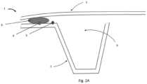
- the bodywork part 1comprises a main body 2 made of plastic and an anti-pinch system, the anti-pinch system comprising a capacitive sensor comprising at least a first conductive wire 4 integrated into the thickness of the main body 2 by welding so as to be flush or not flush with the main body 2, the first conductive wire 4 being located at least partially in a peripheral zone of said main body, said capacitive sensor being capable of detecting the presence of an object or a hand of a user (not shown) in said peripheral zone.
- Exhibit 1 as shown in Figures 1 to 3Bcomprises an added element 3, in this case an outer skin 3 added to the main body 2.
- the sensor capacitive of the anti-pinch system of the part of the invention described in these figurescomprises a second conductive wire 5, also integrated into the thickness of the main body 2 by welding so as to be flush or uneven with the main body 2.
- This second conductive wire 5is also located at least partially in a peripheral zone of said main body 2.
- the first conductive wire 4 and the second conductive wire 5are welded to the main body 2 by applying ultrasonic vibrations so as to be flush and form a relief with the neighboring surface of the main body 2.
- These two conductive wires 4 and 5are elements of the capacitive sensor which further comprises an electronic system (not shown) capable of processing the data received upon detection of an object or a user's hand.
- the capacitive sensoris a subassembly of the anti-pinch system which comprises a control system capable of controlling the actuator responsible for closing and opening the tailgate 1, so as to stop the closing or opening of the latter in the event of a risk of pinching.
- the conductive wires 4 and 5can be welded so as to be flush and thus form a flat surface with the neighboring surface of the main body 2, which further reduces the localized bulk of this specific portion of the main body 2 and protects them even more from any attack since they are then completely embedded in the plastic material.
- the conductive wires 4 and 5are located within the peripheral zone of the main body 2, which makes it possible to optimize the detection of a possible pinching in this sensitive zone of the vehicle, once the tailgate 1 is assembled.
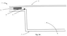
- the main body 2, shown in Figures 2A to 2Ccorresponds to a side pillar of the tailgate 1 while it corresponds to a lower part of the tailgate 1 at Figure 3A And 3B .
- the vehiclemay include other sensitive areas relating to the opening and closing of the tailgate 1 which may therefore include at least one other capacitive sensor, as shown in Figures 2C And 3B .
- This second capacitive sensorsimilar in design to the one previously described, is also a subassembly of the anti-pinch system and comprises a first conductive wire 7 and a second conductive wire 8 welded flush to the surface adjacent to the main body 2, as close as possible to another sensitive area.
- the anti-pinch systemhas several capacitive sensors, which allows it to ensure better detection of risky situations and to refine the instructions that it transmits to the actuator of the tailgate 1.
- the tailgate 1comprises an outer skin 3.
- the latteris attached to the main body 2 and is fixed by a bead of glue 6 located in the peripheral zone of the main body 2.
- one of the two conductive wires 4 or 5is covered by the bead of glue 6 which protects it completely and ensures the durability of said wire, and therefore ultimately of the capacitive sensor, over time.
- the two conductive wires 4 and 5are covered by the adhesive bead 6 and are therefore both protected by the latter.
- the main body 2 and the outer skin 3form a sealed volume 9 within which it is possible to weld the conductive wires 4 and 5, this sealed volume 9 being inaccessible to the user and closest to the edge.
- the wire or one of the conductive wiresmay be integrated on the internal face, facing the main body, of the outer skin.
- one of the conductive wiresmay preferably be integrated flush in the thickness of the main body and may thus be better protected.
- the sensoris provided with two conductive wires, the latter may be integrated simultaneously in the thickness of the main body, which allows, among other things, to be able to integrate them parallel within the thickness of the part, one relative to the other. They may also be integrated by the same device as the device carrying out the application of the bead of glue (to do this, the device may have a head provided with a nozzle for applying the bead of glue and a sonotrode for integrating said wires).
Landscapes
- Engineering & Computer Science (AREA)
- Chemical & Material Sciences (AREA)
- Mechanical Engineering (AREA)
- Life Sciences & Earth Sciences (AREA)
- General Physics & Mathematics (AREA)
- Composite Materials (AREA)
- Physics & Mathematics (AREA)
- General Life Sciences & Earth Sciences (AREA)
- Immunology (AREA)
- Remote Sensing (AREA)
- Chemical Kinetics & Catalysis (AREA)
- Electrochemistry (AREA)
- Health & Medical Sciences (AREA)
- Analytical Chemistry (AREA)
- Biochemistry (AREA)
- General Health & Medical Sciences (AREA)
- Geophysics (AREA)
- Pathology (AREA)
- Geology (AREA)
- Environmental & Geological Engineering (AREA)
- Power-Operated Mechanisms For Wings (AREA)
- Resistance Heating (AREA)
- Switches That Are Operated By Magnetic Or Electric Fields (AREA)
- Manipulator (AREA)
Description
Translated fromFrenchL'invention concerne le domaine de l'industrie automobile et plus spécifiquement les pièces de carrosserie en matière plastique destinées à être monté sur un véhicule automobile.The invention relates to the field of the automobile industry and more specifically to plastic body parts intended to be mounted on a motor vehicle.
Une telle pièce de carrosserie est par exemple connue du document
De nombreux véhicules modernes sont équipés de pièces de de carrosserie en matière plastique, par exemple des ouvrants tels que des hayons arrières ou des portières, équipées de moteur destiné à réaliser les fonctions d'ouverture et de fermeture. De tels ouvrants peuvent être équipés de dispositifs anti-pincement comportant des capteurs capacitifs positionnés en périphérie de l'ouvrant, au niveau des bords latéraux.Many modern vehicles are equipped with plastic body parts, for example openings such as tailgates or doors, equipped with motors intended to perform the opening and closing functions. Such openings can be equipped with anti-pinch devices comprising capacitive sensors positioned on the periphery of the opening, at the lateral edges.
Un capteur capacitif permet de détecter à faible distance une variation de capacité électrique due à la présence d'un objet ou la présence d'un objet dans le champ de détection du capteur.A capacitive sensor can detect at a short distance a variation in electrical capacitance due to the presence of an object or the presence of an object in the detection field of the sensor.
De façon générale, de tels capteurs détectent donc, sans nécessité de contact, la présence d'un objet entrant dans le champ de détection, par détection d'une variation de capacité électrique. Le dispositif stoppe alors la fermeture du hayon avant que l'obstacle soit pincé entre l'ouvrant et la caisse du véhicule.In general, such sensors therefore detect, without the need for contact, the presence of an object entering the detection field, by detecting a variation in electrical capacity. The device then stops the tailgate from closing before the obstacle is pinched between the opening and the body of the vehicle.
De tels capteurs peuvent être utilisés pour détecter la présence d'obstacles dans de nombreux types de fermetures automobiles telles que les lève-vitres électriques, les toits ouvrants, les portes latérales, les portes coulissantes, les hayons.Such sensors can be used to detect the presence of obstacles in many types of automotive closures such as power windows, sunroofs, side doors, sliding doors, tailgates.
De tels capteurs capacitifs présentent l'avantage de pouvoir détecter à courte distance la présence de tous types d'objets ou matériaux, car sensibles aux métaux et aux non-métaux.Such capacitive sensors have the advantage of being able to detect the presence of all types of objects or materials at short distances, as they are sensitive to metals and non-metals.
Un capteur capacitif est basé sur le principe du condensateur, dont la capacité dépend notamment de la nature du milieu diélectrique séparant ses électrodes et de la distance les séparant. De façon générale, ce milieu diélectrique est de l'air. Ainsi tout objet ayant une constante diélectrique ou permittivité relative différente (celle de l'air est de 1) amené à proximité de l'électrode provoque une variation détectable (par exemple, la permittivité du corps humain, est très proche de celle de l'eau qui est de 81). Une détection de cette variation permet de détecter la présence de l'objet.A capacitive sensor is based on the principle of the capacitor, whose capacitance depends in particular on the nature of the dielectric medium separating its electrodes and the distance separating them. Generally speaking, this dielectric medium is air. Thus any object having a different dielectric constant or relative permittivity (that of air is 1) brought close to the electrode causes a detectable variation (for example, the permittivity of the human body is very close to that of water which is 81). Detection of this variation makes it possible to detect the presence of the object.
Une des électrodes du condensateur formant le capteur peut être constituée de fils ou films conducteurs, en particulier métalliques.One of the electrodes of the capacitor forming the sensor can be made of conductive wires or films, particularly metallic.
Les capteurs capacitifs actuellement utilisés dans l'industrie automobile sont généralement des systèmes positionnés sur les ouvrants, au sein des différentes zones sensibles.The capacitive sensors currently used in the automotive industry are generally systems positioned on the openings, within the different sensitive areas.
On appelle « zone sensible » la zone dans laquelle il existe un risque de pincement. Il s'agit notamment, pour un ouvrant arrière, de la zone située entre la périphérie de l'ouvrant et la caisse.The term "sensitive zone" refers to the area in which there is a risk of pinching. In particular, for a rear opening, this includes the area located between the periphery of the opening and the body.
Il existe donc un réel besoin de positionner ces capteurs capacitifs au plus proche de la zone sensible de sorte à pouvoir y assurer la meilleure détection possible.There is therefore a real need to position these capacitive sensors as close as possible to the sensitive area so as to ensure the best possible detection.
Cependant, comme mentionné précédemment, les capteurs capacitifs sont des systèmes qui doivent généralement être positionnés sur l'ouvrant et sont basés sur des fils conducteurs fixés à un support, ce dernier étant par exemple une gaine souple formant un faisceau ou un boitier plastique.However, as mentioned above, capacitive sensors are systems that generally need to be positioned on the opening and are based on conductive wires fixed to a support, the latter being for example a flexible sheath forming a bundle or a plastic box.
Par conséquent, ces systèmes sont encombrants ou rigides et ils sont donc difficiles à intégrer au sein de l'environnement de l'ouvrant, ce qui complexifie, voire même empêche, un positionnement optimal au plus proche d'une zone sensible pour permettre une détection optimale.Consequently, these systems are bulky or rigid and are therefore difficult to integrate into the environment of the opening, which complicates, or even prevents, optimal positioning as close as possible to a sensitive area to allow optimal detection.
En outre, la fixation de ces systèmes capacitifs rapportés nécessite l'ajout d'éléments de fixation qui, en fonction de leur nature, augmentent l'encombrement total du système capacitif et/ou peuvent complexifier l'étape d'assemblage entre ce dernier et la pièce de carrosserie concernée.Furthermore, the fixing of these reported capacitive systems requires the addition of fixing elements which, depending on their nature, increase the total size of the capacitive system and/or can complicate the assembly step between the latter and the bodywork part concerned.
Enfin, ces systèmes sont généralement logés dans une zone visible de l'ouvrant, c'est-à-dire une zone que voit l'utilisateur, lorsque l'ouvrant est en position ouverte. Un tel positionnement, en plus d'être inesthétique, présente des risques puisque le dispositif peut être heurté ou accroché maladroitement par l'utilisateur.Finally, these systems are generally housed in a visible area of the opening, i.e. an area that the user sees when the opening is in the open position. Such positioning, in addition to being unsightly, presents risks since the device can be bumped or clumsily snagged by the user.
De plus, dans le cas d'un support sous la forme d'une gaine formant un faisceau, celui-ci est généralement fixé à l'ouvrant via différents points distants les uns des autres. Chaque point représente dès lors un point à risque puisqu'ils peuvent chacun se détacher sous l'effet des claquements ou des vibrations du véhicules, créant ainsi des bruits parasites désagréables pour l'utilisateur.In addition, in the case of a support in the form of a sheath forming a bundle, this is generally fixed to the opening via different points distant from each other. Each point therefore represents a risk point since they can each become detached under the effect of the slamming or vibrations of the vehicle, thus creating unpleasant parasitic noises for the user.
L'invention a notamment pour but de remédier à tous les désavantages précédemment listés.The invention aims in particular to remedy all the disadvantages listed above.
A cet effet l'invention a pour objet une pièce de carrosserie pour véhicule automobile comprenant un corps principal en matière plastique et un système anti-pincement, le système anti-pincement comprenant un capteur capacitif comprenant au moins un premier fil conducteur intégré dans l'épaisseur du corps principal par soudage de telle sorte à être affleurant ou désaffleurant du corps principal, le premier fil conducteur étant situé au moins partiellement dans une zone périphérique dudit corps principal, ledit capteur capacitif étant apte à détecter la présence d'un objet ou d'une main d'un utilisateur dans ladite zone périphérique.For this purpose, the invention relates to a body part for a motor vehicle comprising a main body made of plastic and an anti-pinch system, the anti-pinch system comprising a capacitive sensor comprising at least a first conductive wire integrated into the thickness of the main body by welding so as to be flush or uneven with the main body, the first conductive wire being located at least partially in a peripheral zone of said body. main, said capacitive sensor being capable of detecting the presence of an object or a user's hand in said peripheral zone.
Ainsi, la pièce de carrosserie selon l'invention offre une détection au plus proche de la zone périphérique du corps principal et au plus proche d'une zone sensible ciblée. Elle permet donc une détection optimisée par le capteur capacitif du système anti-pincement, et ce, puisque le fil conducteur dudit capteur est intégré au plus au plus près du bord du corps principal de la pièce. En outre, la pièce de carrosserie selon l'invention présente l'avantage de comprendre un système anti-pincement tout en maintenant un faible encombrement en épaisseur de son corps principal. A ce titre, par fil conducteur « affleurant ou désaffleurant au corps principal », on entend que le fil conducteur forme, respectivement, une surface en continuité de forme ou un relief avec la surface voisine du corps principal.Thus, the bodywork part according to the invention offers detection as close as possible to the peripheral zone of the main body and as close as possible to a targeted sensitive zone. It therefore allows optimized detection by the capacitive sensor of the anti-pinch system, since the conductive wire of said sensor is integrated as close as possible to the edge of the main body of the part. In addition, the bodywork part according to the invention has the advantage of comprising an anti-pinch system while maintaining a small thickness of its main body. In this respect, by conductive wire "flush or not flush with the main body", it is meant that the conductive wire forms, respectively, a surface in continuity of shape or a relief with the neighboring surface of the main body.
Avantageusement, le capteur capacitif comprend un deuxième fil conducteur intégré dans l'épaisseur du corps principal par soudage de telle sorte à être affleurant ou désaffleurant du corps principal, le deuxième fil conducteur étant situé au moins partiellement dans une zone périphérique dudit corps principal.Advantageously, the capacitive sensor comprises a second conductive wire integrated into the thickness of the main body by welding so as to be flush or uneven with the main body, the second conductive wire being located at least partially in a peripheral zone of said main body.
Dès lors la détection d'un objet dans la zone sensible par le capteur capacitif est optimisée compte tenu de la différence de capacité entre les deux fils conducteurs que génère la présence de cet objet. Plus précisément, l'un des deux fils conducteurs est qualifié de « fil émetteur » tandis que l'autre est qualifié de « fil récepteur ».Therefore, the detection of an object in the sensitive area by the capacitive sensor is optimized taking into account the difference in capacitance between the two conductive wires generated by the presence of this object. More precisely, one of the two conductive wires is called the "transmitter wire" while the other is called the "receiver wire".
Avantageusement, la zone périphérique est une zone s'étendant depuis le bord du corps principal jusqu' à 20 mm dudit bord. Il est ainsi possible de détecter la présence d'un objet au plus proche de la zone sensible. Avantageusement, la zone périphérique s'étend depuis le bord du corps principal jusqu'à 10 mm dudit bord. Encore plus avantageusement, la zone périphérique s'étend depuis le bord du corps principal jusqu'à 5 mm dudit bord.Advantageously, the peripheral zone is a zone extending from the edge of the main body to 20 mm from said edge. It is thus possible to detect the presence of an object as close as possible to the sensitive zone. Advantageously, the peripheral zone extends from the edge of the main body to 10 mm from said edge. Even more advantageously, the peripheral zone extends from the edge of the main body to 5 mm from said edge.
Avantageusement, la soudure des fils conducteurs est réalisée par application de vibrations ultrasoniques.Advantageously, the welding of the conductive wires is carried out by applying ultrasonic vibrations.
Ainsi, il est possible de créer un sillon dans le corps principal et d'y encastrer les fils conducteurs de façon presque simultanée, ce qui rend la soudure à la fois rapide et fiable. Une telle soudure peut être réalisée à l'aide d'une sonotrode via les étapes suivante :
- insertion d'une portion du fil conducteur dans une cavité d'une extrémité libre d'une sonotrode,
- application des vibrations ultrasoniques à la sonotrode et insertion du fil de sorte à créer le sillon dans l'épaisseur en plastique du corps principal et y encastrer le fil.
- inserting a portion of the conductive wire into a cavity of a free end of a sonotrode,
- application of ultrasonic vibrations to the sonotrode and insertion of the wire so as to create the groove in the plastic thickness of the main body and embed the wire there.
Avantageusement, la pièce comprend un élément rapporté sur le corps principal par un cordon de colle, le cordon de colle recouvrant au moins l'un des fils conducteurs.Advantageously, the part comprises an element attached to the main body by a bead of glue, the bead of glue covering at least one of the conductive wires.
Ainsi, le fil conducteur (ou les fils conducteurs) recouvert par le cordon de colle est protégé ce qui assure la pérennité du capteur capacitif et offre donc une sécurité dans la détection d'objet dans la zone sensible considérée.Thus, the conductive wire (or wires) covered by the bead of glue is protected, which ensures the durability of the capacitive sensor and therefore provides security in the detection of objects in the sensitive area considered.
Avantageusement, le corps principal et l'élément rapporté forment un volume étanche dans lequel est situé le premier fil conducteur et/ou le deuxième fil conducteur.Advantageously, the main body and the added element form a sealed volume in which the first conductive wire and/or the second conductive wire is located.
L'invention a également pour objet un véhicule automobile comprenant au moins une pièce de carrosserie selon l'une quelconque des variantes de la pièce de carrosserie de l'invention.The invention also relates to a motor vehicle comprising at least one body part according to any one of the variants of the body part of the invention.
Avantageusement, la pièce de carrosserie est un ouvrant tel qu'un hayon arrière, une porte latérale, un capot ou un toit ouvrant.Advantageously, the body part is an opening such as a rear hatch, a side door, a hood or a sunroof.
L'invention sera mieux comprise à la lecture de la description qui va suivre donnée uniquement à titre d'exemple et faite en se référant aux dessins annexés dans lesquels :
- [
Fig. 1 ] lafigure 1 est une vue en perspective d'un hayon de véhicule automobile selon un mode de réalisation de l'invention, - [
Fig. 2 ] lafigure 2 est un ensemble de vues en coupe (figure 2A ,2B et2C ) du hayon de lafigure 1 selon la coupe II-II, - [
Fig. 3 ] lafigure 3 est un ensemble de vues en coupe (figure 3A et3B ) du hayon de lafigure 1 selon la coupe III-III.
- [
Fig. 1 ] therefigure 1 is a perspective view of a motor vehicle tailgate according to one embodiment of the invention, - [
Fig. 2 ] therefigure 2 is a set of sectional views (Figure 2A ,2B And2C ) from the tailgate of thefigure 1 according to section II-II, - [
Fig. 3 ] therefigure 3 is a set of sectional views (Figure 3A And3B ) from the tailgate of thefigure 1 according to section III-III.
On a représenté sur les
La pièce de carrosserie 1 selon l'invention comprend un corps principal 2 en matière plastique et système anti-pincement, le système anti-pincement comprenant un capteur capacitif comprenant au moins un premier fil conducteur 4 intégré dans l'épaisseur du corps principal 2 par soudage de telle sorte à être affleurant ou désaffleurant du corps principal 2, le premier fil conducteur 4 étant situé au moins partiellement dans une zone périphérique dudit corps principal, ledit capteur capacitif étant apte à détecter la présence d'un objet ou d'une main d'un utilisateur (non représentés) dans ladite zone périphérique.The
La pièce 1 telle que représentée aux
Comme représenté aux
Les fils conducteurs 4 et 5 peuvent être soudés de manière à être affleurants et ainsi former une surface plane avec la surface voisine du corps principal 2, ce qui réduit encore l'encombrement localisé à cette portion spécifique du corps principal 2 et les protège d'autant plus de toute agression puisqu'ils sont alors enchâssés en totalité dans la matière plastique.The
Les fils conducteurs 4 et 5 sont situés au sein de la zone périphérique du corps principal 2 ce qui permet d'optimiser la détection d'un éventuel pincement dans cette zone sensible du véhicule, une fois le hayon 1 assemblé. Le corps principal 2, représenté aux
Néanmoins, le véhicule peut comporter d'autres zones sensibles relatives à l'ouverture et la fermeture du hayon 1 qui peut donc comprendre au moins un autre capteur capacitif, comme représenté aux
Comme mentionné précédemment, le hayon 1 comprend une peau extérieure 3. Cette dernière est rapportée sur le corps principal 2 et est fixée par un cordon de colle 6 situé dans la zone périphérique du corps principal 2.As mentioned above, the
Comme représenté aux
L'invention n'est pas limitée aux modes de réalisation présentés et d'autres modes de réalisation apparaîtront clairement à l'homme du métier. Par exemple, le fil ou l'un des fils conducteurs peut être intégré sur la face interne, en regard du corps principal, de la peau extérieure. Lorsque l'un des fils conducteurs n'est pas intégré au sein du volume étanche il peut de préférence être intégré de manière affleurante dans l'épaisseur du corps principal et peut ainsi être mieux protégé. Lorsque le capteur est pourvu de deux fils conducteurs, ces derniers peuvent être intégrés de manière simultanée dans l'épaisseur du corps principal, ce qui permet entre autres choses de pouvoir les intégrer parallèlement au sein de l'épaisseur de la pièce, l'un par rapport à l'autre. Ils peuvent également être intégrés par le même appareil que l'appareil réalisant la pose du cordon de colle (pour ce faire, l'appareil peut avoir une tête pourvue d'une buse de pose du cordon de colle et d'une sonotrode pour l'intégration desdits fils).The invention is not limited to the embodiments presented and other embodiments will be apparent to those skilled in the art. For example, the wire or one of the conductive wires may be integrated on the internal face, facing the main body, of the outer skin. When one of the conductive wires is not integrated within the sealed volume, it may preferably be integrated flush in the thickness of the main body and may thus be better protected. When the sensor is provided with two conductive wires, the latter may be integrated simultaneously in the thickness of the main body, which allows, among other things, to be able to integrate them parallel within the thickness of the part, one relative to the other. They may also be integrated by the same device as the device carrying out the application of the bead of glue (to do this, the device may have a head provided with a nozzle for applying the bead of glue and a sonotrode for integrating said wires).
- 1 : pièce de carrosserie - hayon1: body part - tailgate
- 2 : corps principal2: main body
- 3 : peau extérieure3: outer skin
- 4 : premier fil conducteur du capteur capacitif4: first conductive wire of the capacitive sensor
- 5 : deuxième fil conducteur du capteur capacitif5: second conductive wire of the capacitive sensor
- 6 : cordon de colle6: glue bead
- 7 : premier fil conducteur d'un second capteur capacitif7: first conductive wire of a second capacitive sensor
- 8 : deuxième fil conducteur du second capteur capacitif8: second conductive wire of the second capacitive sensor
- 9 : volume étanche9: waterproof volume
Claims (8)
- A bodywork part (1) for a motor vehicle comprising a main body (2) made from a plastic material and an anti-pinching system, the anti-pinching system comprising a capacitive sensor comprising at least a first conductive wire (4) integrated into the thickness of the main body by welding so as to be flush with or not flush with the main body (2), the first conductive wire (4) being located at least partially in a peripheral zone of said main body (2), said capacitive sensor being able to detect the presence of an object or a hand of a user in said peripheral zone.
- The bodywork part (1) according to the preceding claim, wherein the capacitive sensor comprises a second conductive wire (5) integrated into the thickness of the main body (2) by welding so as to be flush with or not flush with the main body (2), the second conductive wire (5) being located at least partially in a peripheral zone of said main body (2).
- The bodywork part (1) according to any one of the preceding claims, wherein the peripheral zone is a zone extending from the edge of the main body (2) to 20 mm from said edge.
- The bodywork part (1) according to any one of the preceding claims, wherein the welding of the conductive wires (4, 5) is carried out by applying ultrasonic vibrations.
- The bodywork part (1) according to any one of the preceding claims, comprising an attached element (3) attached to the main body (2) by a bead of adhesive (6), the bead of adhesive (6) covering at least one of the conductive wires (4, 5).
- The bodywork part (1) according to the preceding claim, wherein the main body (2) and the attached element (3) form a sealed volume (9) in which the first conductive wire (4) and/or the second conductive wire (5) is located.
- A motor vehicle comprising at least one bodywork part (1) according
to any one of the preceding claims. - The motor vehicle according to the preceding claim, wherein the
bodywork part (1) is an opening element such as a tailgate (1), a side door, a hood or a sunroof.
Applications Claiming Priority (2)
| Application Number | Priority Date | Filing Date | Title |
|---|---|---|---|
| FR1907967AFR3098785A1 (en) | 2019-07-15 | 2019-07-15 | Method of manufacturing a bodywork element provided with a conductive track |
| FR2005275AFR3098907B1 (en) | 2019-07-15 | 2020-05-20 | Body part with integrated anti-pinch system |
Publications (2)
| Publication Number | Publication Date |
|---|---|
| EP3913180A1 EP3913180A1 (en) | 2021-11-24 |
| EP3913180B1true EP3913180B1 (en) | 2024-10-09 |
Family
ID=69024297
Family Applications (2)
| Application Number | Title | Priority Date | Filing Date |
|---|---|---|---|
| EP20184138.4AActiveEP3766677B1 (en) | 2019-07-15 | 2020-07-06 | Method for manufacturing a bodywork element provided with a conductive track |
| EP21174396.8AActiveEP3913180B1 (en) | 2019-07-15 | 2021-05-18 | Bodywork part with integrated anti-pinching system |
Family Applications Before (1)
| Application Number | Title | Priority Date | Filing Date |
|---|---|---|---|
| EP20184138.4AActiveEP3766677B1 (en) | 2019-07-15 | 2020-07-06 | Method for manufacturing a bodywork element provided with a conductive track |
Country Status (5)
| Country | Link |
|---|---|
| US (1) | US12139952B2 (en) |
| EP (2) | EP3766677B1 (en) |
| JP (1) | JP2021183800A (en) |
| CN (3) | CN112222594A (en) |
| FR (2) | FR3098785A1 (en) |
Families Citing this family (5)
| Publication number | Priority date | Publication date | Assignee | Title |
|---|---|---|---|---|
| FR3098785A1 (en)* | 2019-07-15 | 2021-01-22 | Compagnie Plastic Omnium Se | Method of manufacturing a bodywork element provided with a conductive track |
| DE102021111342A1 (en)* | 2021-05-03 | 2022-11-03 | Kiekert Aktiengesellschaft | Motor vehicle skin component |
| DE102021211354A1 (en)* | 2021-10-07 | 2023-04-13 | Nissha Europe GmbH | Foil-wire assembly and a method for its manufacture |
| CN115067710B (en)* | 2022-07-19 | 2024-03-15 | 慕思健康睡眠股份有限公司 | Anti-pinch method and device applied to electric bed, electric bed and storage medium |
| DE102023121614A1 (en)* | 2023-08-11 | 2025-02-13 | Leonhard Kurz Stiftung & Co. Kg | Method for producing a plastic article and device for producing a plastic article |
Family Cites Families (22)
| Publication number | Priority date | Publication date | Assignee | Title |
|---|---|---|---|---|
| KR100373063B1 (en)* | 1996-02-12 | 2003-05-12 | 만프레트 리츨러 | Wire conductor connection method and device |
| FR2759030B1 (en) | 1997-02-04 | 1999-04-09 | Hutchinson | GUIDE PROFILE OF A MOTORIZED GLASS OR MOBILE PANEL |
| US5783008A (en)* | 1997-03-31 | 1998-07-21 | Ford Global Technologies, Inc. | Apparatus and method for embedding conductors in a non-planar substrate |
| US6377009B1 (en)* | 1999-09-08 | 2002-04-23 | Harald Philipp | Capacitive closure obstruction sensor |
| US6519835B1 (en)* | 2000-08-18 | 2003-02-18 | Watlow Polymer Technologies | Method of formable thermoplastic laminate heated element assembly |
| US8646675B2 (en)* | 2004-11-02 | 2014-02-11 | Hid Global Gmbh | Laying apparatus, contact-making apparatus, movement system, laying and contact-making unit, production system, method for production and a transponder unit |
| JP2006302605A (en)* | 2005-04-19 | 2006-11-02 | Koito Mfg Co Ltd | Manufacturing method of lighting fixture for vehicle, and lighting fixture for vehicle |
| DE102006009998B4 (en)* | 2006-03-03 | 2014-12-24 | Webasto Ag | Motor-actuated component with anti-pinch protection |
| DE102006060385A1 (en)* | 2006-05-01 | 2007-11-08 | Imasys Ag | Wire laying device for use during production of transponder unit , has wire guide for guiding wire in substrate, and melting mechanism for melting wire insulation in area of wire guide, where mechanism is integrated in device |
| US7546671B2 (en)* | 2006-09-26 | 2009-06-16 | Micromechanic And Automation Technology Ltd. | Method of forming an inlay substrate having an antenna wire |
| US20090000196A1 (en)* | 2007-06-27 | 2009-01-01 | Gmglobal Technology Operations, Inc. | Systems and methods for preventing motor vehicle doors from coming into contact with obstacles |
| DE102008035634B4 (en)* | 2008-07-31 | 2018-03-22 | Mayser Gmbh & Co. Kg | Safety edge for detection of obstacles and device for detecting obstacles |
| JP4915706B2 (en)* | 2009-04-15 | 2012-04-11 | 関東自動車工業株式会社 | Back door and disassembling method thereof |
| US9199608B2 (en) | 2009-08-21 | 2015-12-01 | Uusi, Llc | Keyless entry assembly having capacitance sensor operative for detecting objects |
| US10518490B2 (en)* | 2013-03-14 | 2019-12-31 | Board Of Regents, The University Of Texas System | Methods and systems for embedding filaments in 3D structures, structural components, and structural electronic, electromagnetic and electromechanical components/devices |
| DE102012107116A1 (en) | 2012-08-02 | 2014-02-06 | Brose Fahrzeugteile Gmbh & Co. Kommanditgesellschaft, Hallstadt | Method for controlling an adjustment movement of a vehicle closure element with collision avoidance for a lock area and anti-trap system |
| DE102012217086B3 (en)* | 2012-09-21 | 2014-03-20 | Mayser Gmbh & Co. Kg | Capacitive flat sensor for detecting obstacles in area of movable door or flap of motor car, has textile layers connected to edges in which conductors and intermediate layer are received, where layers are formed in leak proof manner |
| CN105051571A (en)* | 2013-03-15 | 2015-11-11 | 麦格纳覆盖件有限公司 | Combination capacitive and resistive obstacle sensor |
| FR3030342B1 (en)* | 2014-12-18 | 2017-05-19 | Renault Sas | DEVICE FOR THE INSTALLATION OF A CONDUCTIVE WIRE FOR WELDING |
| US10329823B2 (en)* | 2016-08-24 | 2019-06-25 | Ford Global Technologies, Llc | Anti-pinch control system for powered vehicle doors |
| FR3058439B1 (en)* | 2016-11-04 | 2018-12-07 | Compagnie Plastic Omnium | CAPACITIVE SENSOR-TYPE ANTI-PINCH DEVICE FOR OPENING A MOTOR VEHICLE |
| FR3098785A1 (en)* | 2019-07-15 | 2021-01-22 | Compagnie Plastic Omnium Se | Method of manufacturing a bodywork element provided with a conductive track |
- 2019
- 2019-07-15FRFR1907967Apatent/FR3098785A1/ennot_activeCeased
- 2020
- 2020-05-20FRFR2005275Apatent/FR3098907B1/enactiveActive
- 2020-07-06EPEP20184138.4Apatent/EP3766677B1/enactiveActive
- 2020-07-10CNCN202010666259.5Apatent/CN112222594A/enactivePending
- 2021
- 2021-02-19CNCN202110189597.9Apatent/CN113985483A/enactivePending
- 2021-02-19CNCN202120377537.5Upatent/CN215449618U/enactiveActive
- 2021-05-18EPEP21174396.8Apatent/EP3913180B1/enactiveActive
- 2021-05-20USUS17/325,536patent/US12139952B2/enactiveActive
- 2021-05-20JPJP2021085193Apatent/JP2021183800A/enactivePending
Also Published As
| Publication number | Publication date |
|---|---|
| CN112222594A (en) | 2021-01-15 |
| US12139952B2 (en) | 2024-11-12 |
| FR3098907B1 (en) | 2022-12-23 |
| JP2021183800A (en) | 2021-12-02 |
| FR3098785A1 (en) | 2021-01-22 |
| US20210363808A1 (en) | 2021-11-25 |
| CN215449618U (en) | 2022-01-07 |
| EP3913180A1 (en) | 2021-11-24 |
| EP3766677B1 (en) | 2021-12-15 |
| FR3098907A1 (en) | 2021-01-22 |
| CN113985483A (en) | 2022-01-28 |
| EP3766677A1 (en) | 2021-01-20 |
Similar Documents
| Publication | Publication Date | Title |
|---|---|---|
| EP3913180B1 (en) | Bodywork part with integrated anti-pinching system | |
| EP1415059B1 (en) | Motor vehicle door handle | |
| FR2781247A1 (en) | SECURITY SYSTEM FOR A MOTOR VEHICLE OPENING ELEMENT HAVING A PROTECTIVE COVER | |
| FR2817663A1 (en) | TACTILE DETECTION DEVICE FOR MOTOR VEHICLE | |
| WO2007134664A1 (en) | Device for detecting an event in a vehicle or in the surroundings of the vehicle | |
| FR2993384A1 (en) | DEVICE FOR DETECTING THE PRESENCE OF A USER, DOOR HANDLE COMPRISING SAID DEVICE AND METHOD FOR CONFIGURING THE ASSOCIATED HANDLE | |
| EP3713795B1 (en) | Fixation system of an obstacle sensing detector for an automobile | |
| WO2018083422A1 (en) | Anti-pinch device of capacitive-sensor type for a motor-vehicle opening | |
| EP1037758A1 (en) | Self-adhesive strip constituting for example a joint for motor vehicle | |
| EP1057673A1 (en) | Anti-nipping device for a sliding door of a motor vehicle | |
| EP1349280A1 (en) | Tight presence detection system, particularly for door handles | |
| EP3795327A1 (en) | Process for manufacturing an element of a coachwork | |
| EP1685997B1 (en) | Vehicle with a pressure-sensitive strip close to the edge of a wing | |
| EP1685996B1 (en) | Automotive vehicle with a wing side covered with a pressure sensitive sheet | |
| EP0390618B1 (en) | Obstacle detector | |
| FR3118608A1 (en) | Trim and/or sealing element for a vehicle provided with a control element for an electrical device | |
| FR2927352A1 (en) | Motorized casement's e.g. power window, opening and closing control method for motor vehicle, involves controlling acceleration of movement of casement for reducing opening time of casement, when casement is moved in opening direction | |
| FR2878998A1 (en) | Intrusion detection system installation method for e.g. door of home/room, involves cutting inert extension, which conceals free end of cable of detection system, for adjusting length of cable to size of casement or frame of opening | |
| WO2020239756A1 (en) | Inductive sensor for vehicle | |
| FR2802343A1 (en) | MOTOR VEHICLE WITH SELECTIVE "HANDS-FREE" ACCESS SYSTEM | |
| FR2828224A1 (en) | Door handle for motor vehicle has tactile sensor and detection electrode with metal blade mounted in handle | |
| FR2720781A1 (en) | Deformable seal for anti-pinch device. | |
| WO2020099057A1 (en) | Vehicle body part element comprising a heating film | |
| FR3044632A1 (en) | BODY COMPONENT OF A REAR OPENING OF A MOTOR VEHICLE CONSTITUTING AN ANTI-PINCH DEVICE | |
| FR2729425A1 (en) | DOOR CLOSING SYSTEM FOR A MOTOR VEHICLE |
Legal Events
| Date | Code | Title | Description |
|---|---|---|---|
| PUAI | Public reference made under article 153(3) epc to a published international application that has entered the european phase | Free format text:ORIGINAL CODE: 0009012 | |
| STAA | Information on the status of an ep patent application or granted ep patent | Free format text:STATUS: THE APPLICATION HAS BEEN PUBLISHED | |
| AK | Designated contracting states | Kind code of ref document:A1 Designated state(s):AL AT BE BG CH CY CZ DE DK EE ES FI FR GB GR HR HU IE IS IT LI LT LU LV MC MK MT NL NO PL PT RO RS SE SI SK SM TR | |
| B565 | Issuance of search results under rule 164(2) epc | Effective date:20211021 | |
| STAA | Information on the status of an ep patent application or granted ep patent | Free format text:STATUS: REQUEST FOR EXAMINATION WAS MADE | |
| 17P | Request for examination filed | Effective date:20220421 | |
| RBV | Designated contracting states (corrected) | Designated state(s):AL AT BE BG CH CY CZ DE DK EE ES FI FR GB GR HR HU IE IS IT LI LT LU LV MC MK MT NL NO PL PT RO RS SE SI SK SM TR | |
| P01 | Opt-out of the competence of the unified patent court (upc) registered | Effective date:20230517 | |
| GRAP | Despatch of communication of intention to grant a patent | Free format text:ORIGINAL CODE: EPIDOSNIGR1 | |
| STAA | Information on the status of an ep patent application or granted ep patent | Free format text:STATUS: GRANT OF PATENT IS INTENDED | |
| INTG | Intention to grant announced | Effective date:20240523 | |
| RAP3 | Party data changed (applicant data changed or rights of an application transferred) | Owner name:OPMOBILITY SE | |
| RAP3 | Party data changed (applicant data changed or rights of an application transferred) | Owner name:OPMOBILITY SE | |
| GRAS | Grant fee paid | Free format text:ORIGINAL CODE: EPIDOSNIGR3 | |
| GRAA | (expected) grant | Free format text:ORIGINAL CODE: 0009210 | |
| STAA | Information on the status of an ep patent application or granted ep patent | Free format text:STATUS: THE PATENT HAS BEEN GRANTED | |
| AK | Designated contracting states | Kind code of ref document:B1 Designated state(s):AL AT BE BG CH CY CZ DE DK EE ES FI FR GB GR HR HU IE IS IT LI LT LU LV MC MK MT NL NO PL PT RO RS SE SI SK SM TR | |
| REG | Reference to a national code | Ref country code:CH Ref legal event code:EP | |
| REG | Reference to a national code | Ref country code:DE Ref legal event code:R096 Ref document number:602021019782 Country of ref document:DE | |
| REG | Reference to a national code | Ref country code:IE Ref legal event code:FG4D Free format text:LANGUAGE OF EP DOCUMENT: FRENCH | |
| REG | Reference to a national code | Ref country code:LT Ref legal event code:MG9D | |
| REG | Reference to a national code | Ref country code:NL Ref legal event code:MP Effective date:20241009 | |
| REG | Reference to a national code | Ref country code:AT Ref legal event code:MK05 Ref document number:1730772 Country of ref document:AT Kind code of ref document:T Effective date:20241009 | |
| PG25 | Lapsed in a contracting state [announced via postgrant information from national office to epo] | Ref country code:NL Free format text:LAPSE BECAUSE OF FAILURE TO SUBMIT A TRANSLATION OF THE DESCRIPTION OR TO PAY THE FEE WITHIN THE PRESCRIBED TIME-LIMIT Effective date:20241009 | |
| PG25 | Lapsed in a contracting state [announced via postgrant information from national office to epo] | Ref country code:NL Free format text:LAPSE BECAUSE OF FAILURE TO SUBMIT A TRANSLATION OF THE DESCRIPTION OR TO PAY THE FEE WITHIN THE PRESCRIBED TIME-LIMIT Effective date:20241009 | |
| PG25 | Lapsed in a contracting state [announced via postgrant information from national office to epo] | Ref country code:PT Free format text:LAPSE BECAUSE OF FAILURE TO SUBMIT A TRANSLATION OF THE DESCRIPTION OR TO PAY THE FEE WITHIN THE PRESCRIBED TIME-LIMIT Effective date:20250210 Ref country code:IS Free format text:LAPSE BECAUSE OF FAILURE TO SUBMIT A TRANSLATION OF THE DESCRIPTION OR TO PAY THE FEE WITHIN THE PRESCRIBED TIME-LIMIT Effective date:20250209 Ref country code:HR Free format text:LAPSE BECAUSE OF FAILURE TO SUBMIT A TRANSLATION OF THE DESCRIPTION OR TO PAY THE FEE WITHIN THE PRESCRIBED TIME-LIMIT Effective date:20241009 | |
| PG25 | Lapsed in a contracting state [announced via postgrant information from national office to epo] | Ref country code:FI Free format text:LAPSE BECAUSE OF FAILURE TO SUBMIT A TRANSLATION OF THE DESCRIPTION OR TO PAY THE FEE WITHIN THE PRESCRIBED TIME-LIMIT Effective date:20241009 | |
| PG25 | Lapsed in a contracting state [announced via postgrant information from national office to epo] | Ref country code:BG Free format text:LAPSE BECAUSE OF FAILURE TO SUBMIT A TRANSLATION OF THE DESCRIPTION OR TO PAY THE FEE WITHIN THE PRESCRIBED TIME-LIMIT Effective date:20241009 | |
| PG25 | Lapsed in a contracting state [announced via postgrant information from national office to epo] | Ref country code:ES Free format text:LAPSE BECAUSE OF FAILURE TO SUBMIT A TRANSLATION OF THE DESCRIPTION OR TO PAY THE FEE WITHIN THE PRESCRIBED TIME-LIMIT Effective date:20241009 | |
| PG25 | Lapsed in a contracting state [announced via postgrant information from national office to epo] | Ref country code:NO Free format text:LAPSE BECAUSE OF FAILURE TO SUBMIT A TRANSLATION OF THE DESCRIPTION OR TO PAY THE FEE WITHIN THE PRESCRIBED TIME-LIMIT Effective date:20250109 | |
| PG25 | Lapsed in a contracting state [announced via postgrant information from national office to epo] | Ref country code:LV Free format text:LAPSE BECAUSE OF FAILURE TO SUBMIT A TRANSLATION OF THE DESCRIPTION OR TO PAY THE FEE WITHIN THE PRESCRIBED TIME-LIMIT Effective date:20241009 Ref country code:GR Free format text:LAPSE BECAUSE OF FAILURE TO SUBMIT A TRANSLATION OF THE DESCRIPTION OR TO PAY THE FEE WITHIN THE PRESCRIBED TIME-LIMIT Effective date:20250110 Ref country code:AT Free format text:LAPSE BECAUSE OF FAILURE TO SUBMIT A TRANSLATION OF THE DESCRIPTION OR TO PAY THE FEE WITHIN THE PRESCRIBED TIME-LIMIT Effective date:20241009 | |
| PG25 | Lapsed in a contracting state [announced via postgrant information from national office to epo] | Ref country code:PL Free format text:LAPSE BECAUSE OF FAILURE TO SUBMIT A TRANSLATION OF THE DESCRIPTION OR TO PAY THE FEE WITHIN THE PRESCRIBED TIME-LIMIT Effective date:20241009 | |
| PG25 | Lapsed in a contracting state [announced via postgrant information from national office to epo] | Ref country code:RS Free format text:LAPSE BECAUSE OF FAILURE TO SUBMIT A TRANSLATION OF THE DESCRIPTION OR TO PAY THE FEE WITHIN THE PRESCRIBED TIME-LIMIT Effective date:20250109 | |
| PG25 | Lapsed in a contracting state [announced via postgrant information from national office to epo] | Ref country code:SM Free format text:LAPSE BECAUSE OF FAILURE TO SUBMIT A TRANSLATION OF THE DESCRIPTION OR TO PAY THE FEE WITHIN THE PRESCRIBED TIME-LIMIT Effective date:20241009 | |
| PGFP | Annual fee paid to national office [announced via postgrant information from national office to epo] | Ref country code:DE Payment date:20250521 Year of fee payment:5 | |
| PG25 | Lapsed in a contracting state [announced via postgrant information from national office to epo] | Ref country code:DK Free format text:LAPSE BECAUSE OF FAILURE TO SUBMIT A TRANSLATION OF THE DESCRIPTION OR TO PAY THE FEE WITHIN THE PRESCRIBED TIME-LIMIT Effective date:20241009 | |
| PGFP | Annual fee paid to national office [announced via postgrant information from national office to epo] | Ref country code:GB Payment date:20250527 Year of fee payment:5 | |
| REG | Reference to a national code | Ref country code:DE Ref legal event code:R097 Ref document number:602021019782 Country of ref document:DE | |
| PG25 | Lapsed in a contracting state [announced via postgrant information from national office to epo] | Ref country code:EE Free format text:LAPSE BECAUSE OF FAILURE TO SUBMIT A TRANSLATION OF THE DESCRIPTION OR TO PAY THE FEE WITHIN THE PRESCRIBED TIME-LIMIT Effective date:20241009 | |
| PGFP | Annual fee paid to national office [announced via postgrant information from national office to epo] | Ref country code:FR Payment date:20250530 Year of fee payment:5 | |
| PG25 | Lapsed in a contracting state [announced via postgrant information from national office to epo] | Ref country code:RO Free format text:LAPSE BECAUSE OF FAILURE TO SUBMIT A TRANSLATION OF THE DESCRIPTION OR TO PAY THE FEE WITHIN THE PRESCRIBED TIME-LIMIT Effective date:20241009 | |
| PG25 | Lapsed in a contracting state [announced via postgrant information from national office to epo] | Ref country code:SK Free format text:LAPSE BECAUSE OF FAILURE TO SUBMIT A TRANSLATION OF THE DESCRIPTION OR TO PAY THE FEE WITHIN THE PRESCRIBED TIME-LIMIT Effective date:20241009 | |
| PG25 | Lapsed in a contracting state [announced via postgrant information from national office to epo] | Ref country code:CZ Free format text:LAPSE BECAUSE OF FAILURE TO SUBMIT A TRANSLATION OF THE DESCRIPTION OR TO PAY THE FEE WITHIN THE PRESCRIBED TIME-LIMIT Effective date:20241009 | |
| PG25 | Lapsed in a contracting state [announced via postgrant information from national office to epo] | Ref country code:IT Free format text:LAPSE BECAUSE OF FAILURE TO SUBMIT A TRANSLATION OF THE DESCRIPTION OR TO PAY THE FEE WITHIN THE PRESCRIBED TIME-LIMIT Effective date:20241009 | |
| PLBE | No opposition filed within time limit | Free format text:ORIGINAL CODE: 0009261 | |
| STAA | Information on the status of an ep patent application or granted ep patent | Free format text:STATUS: NO OPPOSITION FILED WITHIN TIME LIMIT | |
| PG25 | Lapsed in a contracting state [announced via postgrant information from national office to epo] | Ref country code:SE Free format text:LAPSE BECAUSE OF FAILURE TO SUBMIT A TRANSLATION OF THE DESCRIPTION OR TO PAY THE FEE WITHIN THE PRESCRIBED TIME-LIMIT Effective date:20241009 | |
| 26N | No opposition filed | Effective date:20250710 |