EP3911238B1 - Medical device in interventional radiology for real-time guiding of a medical operating needle in a volume - Google Patents
Medical device in interventional radiology for real-time guiding of a medical operating needle in a volumeDownload PDFInfo
- Publication number
- EP3911238B1 EP3911238B1EP20702412.6AEP20702412AEP3911238B1EP 3911238 B1EP3911238 B1EP 3911238B1EP 20702412 AEP20702412 AEP 20702412AEP 3911238 B1EP3911238 B1EP 3911238B1
- Authority
- EP
- European Patent Office
- Prior art keywords
- real
- needle
- virtual
- medical
- volume
- Prior art date
- Legal status (The legal status is an assumption and is not a legal conclusion. Google has not performed a legal analysis and makes no representation as to the accuracy of the status listed.)
- Active
Links
Images


Classifications
- A—HUMAN NECESSITIES
- A61—MEDICAL OR VETERINARY SCIENCE; HYGIENE
- A61B—DIAGNOSIS; SURGERY; IDENTIFICATION
- A61B6/00—Apparatus or devices for radiation diagnosis; Apparatus or devices for radiation diagnosis combined with radiation therapy equipment
- A61B6/46—Arrangements for interfacing with the operator or the patient
- A61B6/461—Displaying means of special interest
- A61B6/462—Displaying means of special interest characterised by constructional features of the display
- A—HUMAN NECESSITIES
- A61—MEDICAL OR VETERINARY SCIENCE; HYGIENE
- A61B—DIAGNOSIS; SURGERY; IDENTIFICATION
- A61B34/00—Computer-aided surgery; Manipulators or robots specially adapted for use in surgery
- A61B34/10—Computer-aided planning, simulation or modelling of surgical operations
- A—HUMAN NECESSITIES
- A61—MEDICAL OR VETERINARY SCIENCE; HYGIENE
- A61B—DIAGNOSIS; SURGERY; IDENTIFICATION
- A61B34/00—Computer-aided surgery; Manipulators or robots specially adapted for use in surgery
- A61B34/20—Surgical navigation systems; Devices for tracking or guiding surgical instruments, e.g. for frameless stereotaxis
- A—HUMAN NECESSITIES
- A61—MEDICAL OR VETERINARY SCIENCE; HYGIENE
- A61B—DIAGNOSIS; SURGERY; IDENTIFICATION
- A61B6/00—Apparatus or devices for radiation diagnosis; Apparatus or devices for radiation diagnosis combined with radiation therapy equipment
- A61B6/02—Arrangements for diagnosis sequentially in different planes; Stereoscopic radiation diagnosis
- A61B6/03—Computed tomography [CT]
- A61B6/032—Transmission computed tomography [CT]
- A—HUMAN NECESSITIES
- A61—MEDICAL OR VETERINARY SCIENCE; HYGIENE
- A61B—DIAGNOSIS; SURGERY; IDENTIFICATION
- A61B6/00—Apparatus or devices for radiation diagnosis; Apparatus or devices for radiation diagnosis combined with radiation therapy equipment
- A61B6/12—Arrangements for detecting or locating foreign bodies
- A—HUMAN NECESSITIES
- A61—MEDICAL OR VETERINARY SCIENCE; HYGIENE
- A61B—DIAGNOSIS; SURGERY; IDENTIFICATION
- A61B6/00—Apparatus or devices for radiation diagnosis; Apparatus or devices for radiation diagnosis combined with radiation therapy equipment
- A61B6/46—Arrangements for interfacing with the operator or the patient
- A61B6/461—Displaying means of special interest
- A61B6/463—Displaying means of special interest characterised by displaying multiple images or images and diagnostic data on one display
- A—HUMAN NECESSITIES
- A61—MEDICAL OR VETERINARY SCIENCE; HYGIENE
- A61B—DIAGNOSIS; SURGERY; IDENTIFICATION
- A61B6/00—Apparatus or devices for radiation diagnosis; Apparatus or devices for radiation diagnosis combined with radiation therapy equipment
- A61B6/46—Arrangements for interfacing with the operator or the patient
- A61B6/461—Displaying means of special interest
- A61B6/466—Displaying means of special interest adapted to display 3D data
- A—HUMAN NECESSITIES
- A61—MEDICAL OR VETERINARY SCIENCE; HYGIENE
- A61B—DIAGNOSIS; SURGERY; IDENTIFICATION
- A61B6/00—Apparatus or devices for radiation diagnosis; Apparatus or devices for radiation diagnosis combined with radiation therapy equipment
- A61B6/52—Devices using data or image processing specially adapted for radiation diagnosis
- A61B6/5211—Devices using data or image processing specially adapted for radiation diagnosis involving processing of medical diagnostic data
- A61B6/5229—Devices using data or image processing specially adapted for radiation diagnosis involving processing of medical diagnostic data combining image data of a patient, e.g. combining a functional image with an anatomical image
- G—PHYSICS
- G06—COMPUTING OR CALCULATING; COUNTING
- G06F—ELECTRIC DIGITAL DATA PROCESSING
- G06F3/00—Input arrangements for transferring data to be processed into a form capable of being handled by the computer; Output arrangements for transferring data from processing unit to output unit, e.g. interface arrangements
- G06F3/01—Input arrangements or combined input and output arrangements for interaction between user and computer
- G06F3/011—Arrangements for interaction with the human body, e.g. for user immersion in virtual reality
- G—PHYSICS
- G06—COMPUTING OR CALCULATING; COUNTING
- G06F—ELECTRIC DIGITAL DATA PROCESSING
- G06F3/00—Input arrangements for transferring data to be processed into a form capable of being handled by the computer; Output arrangements for transferring data from processing unit to output unit, e.g. interface arrangements
- G06F3/01—Input arrangements or combined input and output arrangements for interaction between user and computer
- G06F3/017—Gesture based interaction, e.g. based on a set of recognized hand gestures
- G—PHYSICS
- G06—COMPUTING OR CALCULATING; COUNTING
- G06F—ELECTRIC DIGITAL DATA PROCESSING
- G06F3/00—Input arrangements for transferring data to be processed into a form capable of being handled by the computer; Output arrangements for transferring data from processing unit to output unit, e.g. interface arrangements
- G06F3/01—Input arrangements or combined input and output arrangements for interaction between user and computer
- G06F3/03—Arrangements for converting the position or the displacement of a member into a coded form
- G06F3/033—Pointing devices displaced or positioned by the user, e.g. mice, trackballs, pens or joysticks; Accessories therefor
- G06F3/0346—Pointing devices displaced or positioned by the user, e.g. mice, trackballs, pens or joysticks; Accessories therefor with detection of the device orientation or free movement in a 3D space, e.g. 3D mice, 6-DOF [six degrees of freedom] pointers using gyroscopes, accelerometers or tilt-sensors
- G—PHYSICS
- G06—COMPUTING OR CALCULATING; COUNTING
- G06T—IMAGE DATA PROCESSING OR GENERATION, IN GENERAL
- G06T19/00—Manipulating 3D models or images for computer graphics
- G06T19/006—Mixed reality
- A—HUMAN NECESSITIES
- A61—MEDICAL OR VETERINARY SCIENCE; HYGIENE
- A61B—DIAGNOSIS; SURGERY; IDENTIFICATION
- A61B17/00—Surgical instruments, devices or methods
- A61B17/34—Trocars; Puncturing needles
- A61B17/3403—Needle locating or guiding means
- A—HUMAN NECESSITIES
- A61—MEDICAL OR VETERINARY SCIENCE; HYGIENE
- A61B—DIAGNOSIS; SURGERY; IDENTIFICATION
- A61B34/00—Computer-aided surgery; Manipulators or robots specially adapted for use in surgery
- A61B34/10—Computer-aided planning, simulation or modelling of surgical operations
- A61B2034/101—Computer-aided simulation of surgical operations
- A61B2034/105—Modelling of the patient, e.g. for ligaments or bones
- A—HUMAN NECESSITIES
- A61—MEDICAL OR VETERINARY SCIENCE; HYGIENE
- A61B—DIAGNOSIS; SURGERY; IDENTIFICATION
- A61B34/00—Computer-aided surgery; Manipulators or robots specially adapted for use in surgery
- A61B34/10—Computer-aided planning, simulation or modelling of surgical operations
- A61B2034/107—Visualisation of planned trajectories or target regions
- A—HUMAN NECESSITIES
- A61—MEDICAL OR VETERINARY SCIENCE; HYGIENE
- A61B—DIAGNOSIS; SURGERY; IDENTIFICATION
- A61B34/00—Computer-aided surgery; Manipulators or robots specially adapted for use in surgery
- A61B34/20—Surgical navigation systems; Devices for tracking or guiding surgical instruments, e.g. for frameless stereotaxis
- A61B2034/2046—Tracking techniques
- A61B2034/2051—Electromagnetic tracking systems
- A—HUMAN NECESSITIES
- A61—MEDICAL OR VETERINARY SCIENCE; HYGIENE
- A61B—DIAGNOSIS; SURGERY; IDENTIFICATION
- A61B34/00—Computer-aided surgery; Manipulators or robots specially adapted for use in surgery
- A61B34/20—Surgical navigation systems; Devices for tracking or guiding surgical instruments, e.g. for frameless stereotaxis
- A61B2034/2046—Tracking techniques
- A61B2034/2055—Optical tracking systems
- A—HUMAN NECESSITIES
- A61—MEDICAL OR VETERINARY SCIENCE; HYGIENE
- A61B—DIAGNOSIS; SURGERY; IDENTIFICATION
- A61B90/00—Instruments, implements or accessories specially adapted for surgery or diagnosis and not covered by any of the groups A61B1/00 - A61B50/00, e.g. for luxation treatment or for protecting wound edges
- A61B90/36—Image-producing devices or illumination devices not otherwise provided for
- A61B2090/364—Correlation of different images or relation of image positions in respect to the body
- A—HUMAN NECESSITIES
- A61—MEDICAL OR VETERINARY SCIENCE; HYGIENE
- A61B—DIAGNOSIS; SURGERY; IDENTIFICATION
- A61B90/00—Instruments, implements or accessories specially adapted for surgery or diagnosis and not covered by any of the groups A61B1/00 - A61B50/00, e.g. for luxation treatment or for protecting wound edges
- A61B90/36—Image-producing devices or illumination devices not otherwise provided for
- A61B90/37—Surgical systems with images on a monitor during operation
- A61B2090/376—Surgical systems with images on a monitor during operation using X-rays, e.g. fluoroscopy
- A61B2090/3762—Surgical systems with images on a monitor during operation using X-rays, e.g. fluoroscopy using computed tomography systems [CT]
- A—HUMAN NECESSITIES
- A61—MEDICAL OR VETERINARY SCIENCE; HYGIENE
- A61B—DIAGNOSIS; SURGERY; IDENTIFICATION
- A61B90/00—Instruments, implements or accessories specially adapted for surgery or diagnosis and not covered by any of the groups A61B1/00 - A61B50/00, e.g. for luxation treatment or for protecting wound edges
- A61B90/50—Supports for surgical instruments, e.g. articulated arms
- A61B2090/502—Headgear, e.g. helmet, spectacles
- A—HUMAN NECESSITIES
- A61—MEDICAL OR VETERINARY SCIENCE; HYGIENE
- A61B—DIAGNOSIS; SURGERY; IDENTIFICATION
- A61B6/00—Apparatus or devices for radiation diagnosis; Apparatus or devices for radiation diagnosis combined with radiation therapy equipment
- A61B6/54—Control of apparatus or devices for radiation diagnosis
- A61B6/547—Control of apparatus or devices for radiation diagnosis involving tracking of position of the device or parts of the device
- G—PHYSICS
- G06—COMPUTING OR CALCULATING; COUNTING
- G06T—IMAGE DATA PROCESSING OR GENERATION, IN GENERAL
- G06T2210/00—Indexing scheme for image generation or computer graphics
- G06T2210/41—Medical
Definitions
- the present inventionrelates to a medical device for use in interventional radiology making it possible to guide in real time, continuously and in three dimensions the advance of a needle in a human body towards a target, thanks to mixed reality.
- Image-guided medical interventionsare becoming more common due to technological advances in both sophisticated hardware and available imaging modalities. These interventions can be performed endovascularly or percutaneously and use various imaging modalities such as X-rays (scanner, or with tomography called “cone-beam computed tomography” (CBCT), fluoroscopy, subtracted angiography) , acoustic waves (ultrasound), magnetic resonance (magnetic resonance imaging (MRI)) or even multimodal imaging (or fusion of images from different image modalities mentioned above).
- CBCTcone-beam computed tomography
- acoustic wavesultrasound
- magnetic resonance imagingmagnetic resonance imaging
- multimodal imagingor fusion of images from different image modalities mentioned above.
- the goal of technological advancesis to guide these interventions precisely while limiting the use of iodinated contrast product or X-rays because of their harmful characteristics for the subject (nephrotoxicity and stochastic and deterministic effects on biological tissues, respectively ).
- Percutaneous gesturesare frequently performed by CT or CBCT guidance when they concern interior pulmonary, bone, or deep digestive structures (retroperitoneal or peritoneal).
- Gestures made with a scannerhave the disadvantage of using X-rays with their known deleterious effect on biological tissues and an angle limited to a few degrees (0-15°) from the approach according to the manufacturers. This thus limits the possibility of carrying out certain gestures with quasi-vertical axes and complicates the possibility of carrying out routes initially with more pronounced angles.
- the CBCTalso allows gestures to be performed percutaneously and is restricted by a limited field of view compared to the CT scan and lower image quality. However, the angles of the lanes first can go up to 45°.
- New means of guidancehave been developed, such as electromagnetic guidance using pre-intervention diagnostic images (eg scanner).
- This type of processmakes it possible to advance the needle by simultaneously following the path of the needle on two orthogonal planes within a volume of medical imaging resulting from a new planning imaging acquisition (e.g. scanner) performed immediately before the procedure. This makes it possible to reduce or even eliminate the use of the X-rays necessary during the progression of the needle (monitoring imaging).
- the disadvantages of the systemare the need on the one hand to carry out a preliminary imaging of irradiating planning by scanner and on the other hand to follow simultaneously on the same screen (divided in two) the advance of the needle according to two orthogonal planes. This simultaneous tracking on the two orthogonal planes requires effect training and sustained attention to mentally reconstruct the course, orientation and position of the needle.
- patent publication US2005/203380 A1discloses such an augmented reality navigation method.
- the inventors' devicemakes it possible to visualize in a virtual way the subject and its internal organs extracted from previously acquired and processed medical imaging, and to associate therewith an object such as a needle, itself guided (or localized) in three-dimensions and in real time, for example by electromagnetic waves.
- the operatorcan thus guide his needle until he reaches a target in the human body with a direct view of the subject, his organs, the target and the needle through mixed reality.
- the principleis to perform an intervention using a virtual projection of the subject's organs which are invisible from the outside in the real world due to the skin, tissues, muscles etc., of the human body, but made visible by mixed reality.
- This techniquewould eliminate or at least reduce the use of X-rays and facilitate any type of percutaneous gesture.
- the systemincludes an interface which makes it possible to configure the characteristics of the needle (or other tools) such as its length and its diameter and its virtual appearance.
- the object of the inventionis to allow the operator to guide in three dimensions - subsequently called 3D - and in real time a medical needle 1, 1A in the body 2 of a subject during a radiology session interventional, by mixed reality.
- Mixed realityis a projection of virtual objects representing real objects.
- the interventional radiology medical device with mixed realityallows real-time and 3D guidance of a medical needle 1.1A towards at least one real target 6 in a real volume 3 of body 2 of a subject .
- the target which is represented in all the figuresis the virtual target, but for reasons of simplification, as it visually coincides for the operator with the real target (thanks to the device according to the invention), it was chosen to put the same number 6.
- the mixed reality display means 8can be, for example, a helmet or mixed reality glasses.
- the headset or the mixed reality glasseshave a software interface which makes it possible to load the 3D volume of the subject reconstructed by post-processing from DICOM images (acronym for “Digital imaging and COmmunications in Median”).
- DICOM imagescan be taken from scanner, MRI, CBCT images.
- the imagesare post-processed in order to build a three-dimensional representation of what has been acquired.
- the post-processingconsists of a phase of selection and segmentation of the organs to be reconstructed, then a phase of volume reconstruction from these segmentations.
- a matching phase between the virtual 3D volume of the reconstructed subject and the real subjectis necessary. This fusion phase is called “real subject-virtual subject registration”.
- the dimensions of the virtual objectsare identical, by the glasses/helmet and the ocular projection, to those of the real objects.
- the calculation means 9make it possible to visualize in real time via the visualization means 8, during the intervention, the positioning and the displacement in 3D up to the 3D reconstructed target 6 of the virtual needle 1.1B in the volume 4 reconstructed in pre-recorded 3D; the virtual positioning and the virtual displacement merging through the display means 8 with the real positioning and the real 3D displacement of the medical needle 1.1A in the body 2 of the subject, to guide the displacement by the operator of the medical needle 1.1A in the actual volume 3 to the actual target 6.
- the imaging meansare capable of producing images at the start or during the intervention by scanner, CBCT, ultrasound, so as to allow registration with the medical images previously acquired before the intervention which present reconstructed interest volumes, including the target; in order to compensate for a possible registration defect induced by a movement, a deformation (under the constraint of the needle) of the patient's body.
- the calculation means 9can be configured to produce a second fixed virtual reference frame in the virtual reference frame close to the virtual needle 1.1B to quantify the displacement of the virtual needle 1.1B.
- the medical needle 1.1Ais suitable for use during biopsies, punctures, drainages and ablations for any type of target in the human body 2 (examples: skin, breast, bone, thoracic, abdominal or arterial and venous vascular) .
- the medical images usedare of the DICOM type (eg: scanner, MRI and CBCT) and are processed (eg: segmentation, thresholding, 3D volume modelling).
- the volume 4 reconstructed in 3Dpresents a reconstructed part such as the surface of the subject (example: the skin), organs of interest and the target(s).
- the medical devicemay comprise second means 10A, 10B for real-time 3D location and orientation of all or part of the subject to determine its position and its orientation in the real frame of reference, and the calculation means communicate to these second means and are configured to continuously recalculate the movements of the needle in order to ensure continuous readjustment between the virtual and real repositories.
- the virtual needle 1.1Bmay have visible markers such as a scale with segments 13A, 13B (example: color code) making it possible to indicate the length of the virtual needle 1.1B.
- the virtual needle 1.1Bmay have only an outline which coincides with the outline of the real needle in mixed reality.
- the calculation means 9can be connected to sound signaling means to indicate by a sound signal to the operator the distance which separates the right medical needle 1.1A from the interior structures of interest 5A, 5B, 5C and from the targets 6.
- This sound signalcan present an intensity or a frequency proportional to this distance or any other type of information: message etc.
- These sound signaling meanscan be connected to the display means.
- Figure 1Arepresents the real vision of the subject of the invention (here represented by a cube), and the Figure 1B represents a mixed view of the subject and its target through mixed reality glasses/headset. It is thus possible to see through the subject and to see the target and its location (ie it is possible to see through the skin and the organs).
- FIG. 1Crepresents a mixed view of the subject, its target as well as the needle on which the electromagnetic transmitter is fixed, itself being connected to the electromagnetic receiver.
- FIG. 1Drepresents a mixed view of the subject and its target as well as the needle which progresses in the subject to reach the target.
- the movement of the needleis visualized with its virtual counterpart in 3D and in real time.
- FIG. 1Erepresents a mixed view of the subject and its target as well as the needle that hit the target.
- the operatoruses a needle.
- an electromagnetic wave transmitterwhich makes it possible to know its position and its orientation in space.
- This needlewhose characteristics (length, diameter) have been predefined through the user interface of the mixed reality helmet/glasses, needs to be merged beforehand with its virtual counterpart. This fusion phase is called “virtual needle 1.1B real needle 1.1A realignment”.
- the localization systemcan use any kind of localization method (electromagnetic waves, optical, mechanical).
- an electromagnetic wave receiver boxis fixed on the table, close to the target.
- the needlecan be inserted at any position and follow any angle according to the choice of the operator.
- the operatorprogressively advances the needle thanks to mixed reality guidance of the position of the needle until reaching his target ( Figure 1D ).
- the position and orientation of the needleare obtained in real time by the electromagnetic localization system. From this information, the virtual needle 1.1B (previously merged with the real needle) is entirely and permanently visible thanks to mixed reality, even if the real needle is no longer completely visible since in the body 2 of the subject.
- the operator's handsare thus free, and his gaze is increased and directed towards the subject and his target.
- the reconstructed volumeis merged and statically keyed to the subject's body 2.
- the entire body 2 of the subject and its increased projection of its organsare thus merged and visible in its field of vision when the needle advances and the operator does not need a screen for guidance.
- the base of the needleis where the sensor 10a is located, it must be in the right position so that the real corresponds to the virtual, this is the role of the "virtual needle resetting" step 1.1B - real needle” seen previously.
- Selecting a model to loadis done through a graphical interface displayed in mixed reality.
- the 3D modelonce loaded, is merged with the subject's body 2 in the real world via a manual calibration process obtained by superimposing the 3D model and the subject's body 2.
- This calibration processis called “virtual subject-real subject registration”. It is performed using the graphical interface which displays virtual buttons but it can also be performed using a gamepad connected to the headset or using a wireless keyboard connected to the headset .
- the goalis to now calibrate the benchmarks of the virtual helmet, the real world and the real and virtual needles.
- the "virtual needle 1.1B - real needle” registrationcan be carried out in two ways.
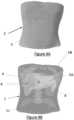
- FIG. 4Arepresents the actual external view of the subject's abdomen.
- THE figures 4B to 4Erepresent the view by the operator (doctor or other, etc.) wearing mixed reality glasses/headset of the subject's abdomen, who sees the 3D reconstructed volume projected and merged with and onto the real volume.
- FIG 4Brepresents the view of the subject's abdomen and its reconstructed volume (visualization of the liver 5A, of three hepatic nodules 6 including a target nodule, of the ribs 5B and of the spine 5C obtained after processing DICOM images of his abdominal scanner) by mixed reality through glasses/helmet.
- Fig. 4Crepresents the mixed reality view of the subject (real and virtual) with the needle and its virtual counterpart, the transmitter and the receiver.
- Needle 1is now in liver 5A and is directed by the operator in real time and in 3D to its target.
- FIG. 4Erepresents the needle 1 which has reached its target thanks to the device
- FIG. 4Frepresents the real vision (without helmet/glasses) of the subject and the medical needle 1A.
Landscapes
- Engineering & Computer Science (AREA)
- Health & Medical Sciences (AREA)
- Life Sciences & Earth Sciences (AREA)
- Medical Informatics (AREA)
- Physics & Mathematics (AREA)
- Surgery (AREA)
- Animal Behavior & Ethology (AREA)
- Veterinary Medicine (AREA)
- Nuclear Medicine, Radiotherapy & Molecular Imaging (AREA)
- Theoretical Computer Science (AREA)
- Public Health (AREA)
- General Health & Medical Sciences (AREA)
- Biomedical Technology (AREA)
- Heart & Thoracic Surgery (AREA)
- Molecular Biology (AREA)
- General Engineering & Computer Science (AREA)
- Human Computer Interaction (AREA)
- Radiology & Medical Imaging (AREA)
- Pathology (AREA)
- High Energy & Nuclear Physics (AREA)
- Biophysics (AREA)
- Optics & Photonics (AREA)
- General Physics & Mathematics (AREA)
- Robotics (AREA)
- Pulmonology (AREA)
- Computer Vision & Pattern Recognition (AREA)
- Computer Graphics (AREA)
- Computer Hardware Design (AREA)
- Software Systems (AREA)
- Apparatus For Radiation Diagnosis (AREA)
- Magnetic Resonance Imaging Apparatus (AREA)
- Surgical Instruments (AREA)
- Ultra Sonic Daignosis Equipment (AREA)
Description
Translated fromFrenchLa présente invention concerne un dispositif médical pour un usage en radiologie interventionnelle permettant de guider en temps réel, en continu et en trois dimensions l'avancée d'une aiguille dans un corps humain vers une cible, grâce à la réalité mixte.The present invention relates to a medical device for use in interventional radiology making it possible to guide in real time, continuously and in three dimensions the advance of a needle in a human body towards a target, thanks to mixed reality.
Les interventions médicales guidées par l'image sont de plus en plus fréquentes par les avancées technologiques qui concernent à la fois le matériel sophistiqué et les modalités d'imagerie disponibles. Ces interventions peuvent être effectuées par voie endovasculaire ou par voie percutanée et utilisent diverses modalités d'imagerie telles que les rayons X (scanner, ou avec la tomographie dite en anglais « cone-beam computed tomography » (CBCT), fluoroscopie, angiographie soustraite), les ondes acoustiques (échographie), la résonance magnétique (imagerie par résonance magnétique (IRM)) ou encore l'imagerie multimodale (ou fusion d'images issues de différentes modalités d'images citées ci-dessus). Le but des avancées technologiques est de guider ces interventions de façon précise tout en limitant l'usage de produit de contraste iodé ou des rayons X du fait de leurs caractères néfastes pour le sujet (néphrotoxicité et effets stochastiques et déterministes sur les tissus biologiques, respectivement).Image-guided medical interventions are becoming more common due to technological advances in both sophisticated hardware and available imaging modalities. These interventions can be performed endovascularly or percutaneously and use various imaging modalities such as X-rays (scanner, or with tomography called "cone-beam computed tomography" (CBCT), fluoroscopy, subtracted angiography) , acoustic waves (ultrasound), magnetic resonance (magnetic resonance imaging (MRI)) or even multimodal imaging (or fusion of images from different image modalities mentioned above). The goal of technological advances is to guide these interventions precisely while limiting the use of iodinated contrast product or X-rays because of their harmful characteristics for the subject (nephrotoxicity and stochastic and deterministic effects on biological tissues, respectively ).
Les gestes réalisés par voie percutanée permettent de réaliser des biopsies, des ponctions, des drainages et des ablations. Les gestes percutanés sont fréquemment réalisés par guidage scanner ou CBCT lorsqu'ils concernent des structures intérieures pulmonaires, osseuses, ou digestives profondes (rétropéritonéales ou péritonéales). Les gestes réalisés en scanner présentent pour inconvénient l'usage de rayons X avec leur effet délétère connu sur les tissus biologiques et un angle limité à quelques degrés (0-15°) de la voie d'abord selon les constructeurs. Ceci limite ainsi la possibilité de réaliser certains gestes avec des axes quasi-verticaux et compliquent la possibilité de réaliser des voies d'abord avec des angles plus prononcés.Procedures performed percutaneously allow biopsies, punctures, drainages and ablations to be performed. Percutaneous gestures are frequently performed by CT or CBCT guidance when they concern interior pulmonary, bone, or deep digestive structures (retroperitoneal or peritoneal). Gestures made with a scanner have the disadvantage of using X-rays with their known deleterious effect on biological tissues and an angle limited to a few degrees (0-15°) from the approach according to the manufacturers. This thus limits the possibility of carrying out certain gestures with quasi-vertical axes and complicates the possibility of carrying out routes initially with more pronounced angles.
Le CBCT permet également de réaliser des gestes par voie percutanée et est restreint par un champ de vue limité par rapport au scanner et une qualité d'images moindre. Cependant, les angles des voies d'abord peuvent aller jusqu'à 45°.The CBCT also allows gestures to be performed percutaneously and is restricted by a limited field of view compared to the CT scan and lower image quality. However, the angles of the lanes first can go up to 45°.
L'inconvénient majeur de ces moyens de guidage (scanner et CBCT) est en effet l'usage préalable des rayons X pour guider le geste (imagerie de planification réalisée immédiatement avant le geste) mais également pour réaliser des imageries de contrôle(s) lors de l'avancée progressive de l'aiguille afin de vérifier le bon positionnement de l'aiguille. Ces imageries de contrôle accroissent davantage les temps d'intervention avec des risques de complications inhérentes, de mouvements du sujet et donc d'échec de l'intervention et d'irradiation accrue.The major drawback of these means of guidance (scanner and CBCT) is in fact the prior use of X-rays to guide the gesture (planning imaging carried out immediately before the gesture) but also to carry out control imaging(s) during of the progressive advance of the needle in order to check the correct positioning of the needle. These control imagings further increase the intervention times with the risk of inherent complications, subject movements and therefore failure of the intervention and increased irradiation.
De nouveaux moyens de guidage ont été développés comme le guidage électromagnétique utilisant les images diagnostiques pré-interventions (ex : scanner). Ce type de procédé permet d'avancer l'aiguille en suivant simultanément le trajet de l'aiguille sur deux plans orthogonaux au sein d'un volume d'imagerie médicale issu d'une nouvelle acquisition d'imagerie de planification (ex : scanner) réalisée immédiatement avant le geste. Ceci permet de réduire voire de s'affranchir de l'usage des rayons X nécessaires lors de la progression de l'aiguille (imagerie de contrôle).New means of guidance have been developed, such as electromagnetic guidance using pre-intervention diagnostic images (eg scanner). This type of process makes it possible to advance the needle by simultaneously following the path of the needle on two orthogonal planes within a volume of medical imaging resulting from a new planning imaging acquisition (e.g. scanner) performed immediately before the procedure. This makes it possible to reduce or even eliminate the use of the X-rays necessary during the progression of the needle (monitoring imaging).
Les désavantages du système sont la nécessité d'une part de réaliser une imagerie préalable de planification irradiante par scanner et d'autre part de suivre simultanément sur un même écran (divisé en deux) l'avancée de l'aiguille selon deux plans orthogonaux. Ce suivi simultané sur les deux plans orthogonaux requiert en effet un entraînement et une attention soutenue pour reconstituer mentalement le parcours, l'orientation et la position de l'aiguille.The disadvantages of the system are the need on the one hand to carry out a preliminary imaging of irradiating planning by scanner and on the other hand to follow simultaneously on the same screen (divided in two) the advance of the needle according to two orthogonal planes. This simultaneous tracking on the two orthogonal planes requires effect training and sustained attention to mentally reconstruct the course, orientation and position of the needle.
La réalité mixte offre de nouveaux horizons en termes de guidage et s'introduit progressivement dans les salles opératoires et de radiologie interventionnelle. Celle-ci est aujourd'hui essentiellement utilisée pour la planification des interventions par la représentation en 3D d'images post-traitées issues d'imagerie médicale de type DICOM d'un sujet. Elle permet également de visualiser directement les images de fluoroscopie dynamique permettant le guidage directement dans le champ de vision de l'opérateur et non sur un écran.Mixed reality offers new horizons in terms of guidance and is gradually being introduced into operating rooms and interventional radiology. This is now mainly used for planning interventions by the 3D representation of post-processed images from DICOM-type medical imaging of a subject. It also allows direct visualization of dynamic fluoroscopy images allowing guidance directly in the operator's field of vision and not on a screen.
La publication de brevet
La présente invention présente un dispositif médical de radiologie interventionnelle avec réalité mixte, permettant un guidage en temps réel et en 3D d'une aiguille médicale droite pour réaliser une ponction, biopsie, drainage ou ablation, vers au moins une cible réelle dans un volume réel de corps d'un sujet, comprenant :
- des moyens d'imagerie (fichiers DICOM de type scanner, IRM, CBCT, Pet scanner ou IRM, échographie) ;
- un volume reconstruit en 3D du volume réel, à partir d'images médicales préalablement acquises avant l'intervention issues d'images DICOM, incluant le volume reconstruit en 3D avec des structures intérieures d'intérêt et une ou plusieurs cible reconstruite en 3D correspondant à la cible réelle;
- des moyens de stockage du volume reconstruit en 3D, pré-enregistré avant l'intervention, ces moyens de stockage étant reliés (communiquent avec ou sans fil) aux moyens d'imagerie ;
- des moyens de visualisation par réalité mixte pour visualiser le volume reconstruit en 3D dans un référentiel virtuel de référence, destinés à être portés par un opérateur ;
- les moyens de visualisation par réalité mixte étant reliés (communiquent avec ou sans fil) à des moyens de calcul qui permettent de fusionner le volume reconstruit en 3D avec le volume réel;
- le volume reconstruit en 3D, une fois fusionné, demeurant stable et figé dans l'espace et dans le temps sur le volume réel, la cible reconstruite 3D étant fusionnée avec la cible réelle,
- une aiguille médicale droite destinée à être manipulée par l'opérateur dans la partie du corps jusqu'à la cible réelle ;
- des moyens de localisation et d'orientation en 3D par ondes électromagnétiques, en temps réel, de l'aiguille médicale droite dans la partie du corps, reliés à l'aiguille médicale par un seul émetteur situé à la base de l'aiguille ; donnant sa position par rapport à un récepteur et dont la position est connue ;
- les moyens de calcul communiquant avec les moyens d'imagerie médicale, les moyens de stockage, les moyens de visualisation, et les moyens de localisation et d'orientation en 3D,
- et recevant les coordonnées des moyens de visualisation dans le repère réel, et le positionnement et l'orientation en 3D de l'aiguille médicale droite dans le référentiel réel,
les moyens de calcul étant configurés pour :- i) déterminer les déplacements et rotations en temps réel des moyens de visualisation (8) dans le référentiel réel,
- ii) déterminer la position du volume réel dans le référentiel réel,
- iii) créer une aiguille virtuelle droite fusionnée avec l'aiguille médicale réelle lors d'une étape de fusion, sur leur longueur, forme et positionnement, en tenant compte :
- du recalage en temps réel (synchronisation automatique avec correction manuelle possible) entre le référentiel virtuel de référence et le référentiel réel qui est fonction des déplacements et rotations en temps réel des moyens de visualisation dans le référentiel réel,
- du positionnement de l'aiguille médicale droite dans le référentiel réel et transmis aux moyens de calcul, par les moyens de localisation et d'orientation en 3D
- de la forme et de la longueur de l'aiguille médicale droite intégrés dans les moyens de calcul,
- afin de visualiser en temps réel à travers les moyens de visualisation, lors de l'intervention, le positionnement et le déplacement en 3D restant à parcourir jusqu'à la cible reconstruite 3D de l'aiguille virtuelle droite dans le volume reconstruit en 3D préenregistré ;
- le positionnement virtuel et le déplacement virtuel fusionnant en temps réel à travers le moyens de visualisation, avec le positionnement réel et le déplacement en 3D réel de l'aiguille médicale droite hors et dans le corps du sujet,
- pour guider en temps réel le déplacement par l'opérateur de l'aiguille médicale droite dans le volume réel du corps vers la cible réelle, jusqu'à ce que l'extrémité de l'aiguille médicale droite, atteigne la cible réelle du volume réel,
- en suivant le déplacement en 3D de l'aiguille virtuelle droite restant à parcourir jusqu'à la cible reconstruite 3D, dans le volume reconstruit en 3D préenregistré et fusionné sur le volume réel.
structures intérieures
- imaging means (DICOM scanner, MRI, CBCT, PET scanner or MRI, ultrasound files);
- a 3D reconstructed volume of the real volume, from medical images previously acquired before the intervention from DICOM images, including the 3D reconstructed volume with interior structures of interest and one or more 3D reconstructed targets corresponding to the actual target;
- means for storing the volume reconstructed in 3D, pre-recorded before the intervention, these storage means being connected (communicate with or without wire) to the imaging means;
- mixed reality visualization means for visualizing the reconstructed volume in 3D in a virtual reference repository, intended to be worn by an operator;
- the mixed reality display means being connected (communicate with or without wire) to calculation means which make it possible to merge the volume reconstructed in 3D with the real volume;
- the 3D reconstructed volume, once merged, remaining stable and frozen in space and time on the real volume, the 3D reconstructed target being merged with the real target,
- a straight medical needle to be manipulated by the operator in the body part to the actual target;
- means of location and orientation in 3D by electromagnetic waves, in real time, of the right medical needle in the part of the body, connected to the medical needle by a single transmitter located at the base of the needle; giving its position relative to a receiver and whose position is known;
- the calculation means communicating with the medical imaging means, the storage means, the visualization means, and the 3D localization and orientation means,
- and receiving the coordinates of the display means in the real frame of reference, and the 3D positioning and orientation of the right medical needle in the real frame of reference,
the calculation means being configured for:- i) determining the displacements and rotations in real time of the display means (8) in the real repository,
- ii) determine the position of the real volume in the real repository,
- iii) create a straight virtual needle fused with the real medical needle during a fusion step, on their length, shape and positioning, taking into account:
- real-time readjustment (automatic synchronization with possible manual correction) between the virtual reference repository and the real repository which depends on the real-time movements and rotations of the display means in the real repository,
- the positioning of the right medical needle in the real repository and transmitted to the calculation means, by the 3D localization and orientation means
- the shape and length of the straight medical needle integrated into the calculation means,
- in order to visualize in real time through the visualization means, during the intervention, the positioning and the 3D displacement remaining to be traversed as far as the 3D reconstructed target of the right virtual needle in the prerecorded 3D reconstructed volume;
- the virtual positioning and the virtual displacement merging in real time through the means of visualization, with the real positioning and the real 3D displacement of the right medical needle out and in the body of the subject,
- to guide the operator's movement of the straight medical needle in real time in the actual volume of the body to the actual target, until the end of the straight medical needle, reaches the actual target of the actual volume ,
- following the 3D displacement of the right virtual needle remaining to be traveled to the 3D reconstructed target, in the 3D reconstructed volume prerecorded and merged on the real volume.
interior structures
Le dispositif des inventeurs permet de visualiser de façon virtuelle le sujet et ses organes internes extraits d'imagerie médicale préalablement acquise et traitée, et d'y associer un objet comme une aiguille, elle-même guidée (ou localisée) en trois-dimensions et en temps réel par exemple par des ondes électromagnétiques.The inventors' device makes it possible to visualize in a virtual way the subject and its internal organs extracted from previously acquired and processed medical imaging, and to associate therewith an object such as a needle, itself guided (or localized) in three-dimensions and in real time, for example by electromagnetic waves.
L'opérateur peut ainsi guider son aiguille jusqu'à atteindre une cible dans le corps humain avec une vision directe du sujet, ses organes, la cible et l'aiguille par la réalité mixte. Le principe est de réaliser une intervention à l'aide d'une projection virtuelle des organes du sujet qui sont invisibles de l'extérieur dans le monde réel en raison de la peau, des tissus, des muscles etc.. , du corps humain, mais rendu visible par la réalité mixte.The operator can thus guide his needle until he reaches a target in the human body with a direct view of the subject, his organs, the target and the needle through mixed reality. The principle is to perform an intervention using a virtual projection of the subject's organs which are invisible from the outside in the real world due to the skin, tissues, muscles etc., of the human body, but made visible by mixed reality.
Cette technique permettrait de s'affranchir ou du moins de réduire l'usage des rayons X et de faciliter tout type de geste percutané.This technique would eliminate or at least reduce the use of X-rays and facilitate any type of percutaneous gesture.
Dans une réalisation, le dispositif médical selon l'invention présente :
- une aiguille qui doit être insérée dans le corps d'un sujet humain afin qu'elle atteigne une cible ;
- un émetteur électromagnétique fixé sur la base de l'aiguille ;
- des moyens d'imagerie médicale ;
- un casque/lunette de réalité mixte qui affiche en 3D :
- 1) les objets 3D (organes, tissus) obtenus par traitement des images DICOM (scanner, IRM ou CBCT) préalablement acquises et traitées du sujet et recalées avec la position réelle de celui-ci ;
- 2) l'aiguille virtuelle
- un récepteur électromagnétique local posé sur la table du sujet ;
- une interface utilisateur visualisée dans les lunettes de réalité mixte qui permet de fusionner préalablement le sujet avec son propre volume post-traité et d'associer en temps réel le positionnement et l'orientation spatiale de l'aiguille par le système électromagnétique.
- a needle that must be inserted into the body of a human subject in order for it to reach a target;
- an electromagnetic transmitter attached to the base of the needle;
- medical imaging means;
- a mixed reality headset/glasses that displays in 3D:
- 1) 3D objects (organs, tissues) obtained by processing DICOM images (scanner, MRI or CBCT) previously acquired and processed of the subject and registered with the latter's real position;
- 2) the virtual needle
- a local electromagnetic receiver placed on the subject's table;
- a user interface visualized in the mixed reality glasses that allows to pre-merge the subject with its own post-processed volume and to associate in real time the positioning and the spatial orientation of the needle by the electromagnetic system.
Le système comprend une interface qui permet de configurer les caractéristiques de l'aiguille (ou autre outils) comme sa longueur et son diamètre et son apparence virtuelle.The system includes an interface which makes it possible to configure the characteristics of the needle (or other tools) such as its length and its diameter and its virtual appearance.
D'autres objectifs, caractéristiques et avantages sortiront de la description détaillée qui suit en référence aux dessins donnés à titre illustratif et non limitatif parmi lesquels :
- les
figures 1A à 1F représentent le principe de l'invention ; - la
figure 2 représente l'aiguille virtuelle avec des indications de couleur (et de longueur) ; - la
figure 3 représente le casque avec les moyens de calcul et de stockage ; - les
figures 4A à 4G représentent une illustration d'application du prototype pour une biopsie d'un nodule hépatique chez un être humain.
- THE
figures 1A to 1F represent the principle of the invention; - there
picture 2 - there
picture 3 - THE
figures 4A to 4G represent an illustration of application of the prototype for a biopsy of a hepatic nodule in a human being.
Le but de l'invention est de permettre à l'opérateur de guider en trois dimensions - nommé par la suite 3D- et en temps réel une aiguille médicale 1, 1A dans le corps 2 d'un sujet lors d'une séance de radiologie interventionnelle, par réalité mixte.The object of the invention is to allow the operator to guide in three dimensions - subsequently called 3D - and in real time a
La réalité mixte est une projection d'objets virtuels représentant des objets réels.Mixed reality is a projection of virtual objects representing real objects.
La réalité mixte est une réalité augmentée.Mixed reality is augmented reality.
Sur les figures, par souci de simplification,
- l'aiguille médicale a été représentée par le numéro « 1 » quand elle est fusionnée avec l'aiguille virtuelle (vision avec les moyens de visualisation par réalité mixte ;
figures 4C, 4D ,4F ) et par le numéro « 1A » quand elle est seule (vision sans les moyens de visualisation par réalité mixte ;figure 4G ) ; - l'aiguille virtuelle a été représentée par le numéro « 1 » quand elle est fusionnée avec l'aiguille médicale (vision avec les moyens de visualisation par réalité mixte ;
figures 4C, 4D ,4F ) et par le numéro « 1B » quand elle est la seule visible avec le moyen de visualisation par réalité mixte (figures 2 ,4D ,4F , et même si elle est demeure fusionnée dans la réalité à l'aiguille médicale qui n'est pas visible).
- the medical needle was represented by the number "1" when it is merged with the virtual needle (vision with the means of visualization by mixed reality;
figures 4C, 4D ,4F ) and by the number "1A" when she is alone (vision without the means of visualization by mixed reality;figure 4G ); - the virtual needle was represented by the number "1" when it is merged with the medical needle (vision with the means of visualization by mixed reality;
figures 4C, 4D ,4F ) and by the number "1B" when it is the only one visible with the means of visualization by mixed reality (figure 2 ,4D ,4F , and even if it remains fused in reality to the medical needle which is not visible).
Le dispositif médical de radiologie interventionnelle avec réalité mixte, selon l'invention, permet un guidage en temps réel et 3D d'une aiguille médicale 1,1A vers au moins une cible 6 réelle dans un volume réel 3 de corps 2 d'un sujet.The interventional radiology medical device with mixed reality, according to the invention, allows real-time and 3D guidance of a medical needle 1.1A towards at least one
La cible qui est représentée sur l'ensemble des figures est la cible virtuelle, mais pour des raisons de simplification, comme elle coïncide visuellement pour l'opérateur avec la cible réelle (grâce au dispositif selon l'invention), il a été choisi de mettre le même numéro 6.The target which is represented in all the figures is the virtual target, but for reasons of simplification, as it visually coincides for the operator with the real target (thanks to the device according to the invention), it was chosen to put the
Il présente :
un volume 4 reconstruit en 3D duvolume réel 3, à partir d'images médicales préalablement acquises avant l'intervention, par des moyens d'imagerie 7a ;
- des moyens de stockage 7b du
volume 4 reconstruit en 3D, pré-enregistré avant l'intervention ; - des moyens de visualisation 8 par réalité mixte pour visualiser le
volume 4 reconstruit en 3D dans un référentiel virtuel de référence, destinés à être portés par un opérateur ;
- l es moyens de visualisation 8 par réalité mixte étant reliés (communiquent avec ou sans fil) à des moyens de calcul 9 qui permettent de fusionner le
volume 4 reconstruit en 3D avec levolume réel 3; l e volume 4 reconstruit en 3D, une fois fusionné, demeurant stable dans l'espace et dans le temps sur levolume réel 3,la cible 6 reconstruite 3D étant fusionnée avec la cible 6 réelle.
- a
volume 4 reconstructed in 3D of thereal volume 3, from medical images previously acquired before the operation, by imaging means 7a;
- storage means 7b of
volume 4 reconstructed in 3D, pre-recorded before the intervention; - means of
visualization 8 by mixed reality to visualize thevolume 4 reconstructed in 3D in a virtual reference frame, intended to be worn by an operator;
- the display means 8 by mixed reality being connected (communicate with or without wire) to calculation means 9 which make it possible to merge the
volume 4 reconstructed in 3D with thereal volume 3; - the
volume 4 reconstructed in 3D, once merged, remaining stable in space and in time on thereal volume 3, thetarget 6 reconstructed 3D being merged with thereal target 6.
Les moyens de visualisation 8 par réalité mixte peuvent être par exemple un casque ou des lunettes de réalité mixte.The mixed reality display means 8 can be, for example, a helmet or mixed reality glasses.
Le casque ou les lunettes de réalité mixte possèdent une interface logicielle qui permet de charger le volume 3D du sujet reconstruit par post traitement à partir d'images DICOM (acronyme en anglais de « Digital imaging and COmmunications in Médiane »). Les images DICOM peuvent être issues d'images de scanner, IRM, CBCT. Les images sont post-traitées afin de construire une représentation tridimensionnelle de ce qui a été acquis. Le post traitement consiste en une phase de sélection et de segmentation des organes à reconstruire, puis une phase de reconstruction volumique à partir de ces segmentations. Enfin, une phase de mise en correspondance entre le volume 3D virtuel du sujet reconstruit et le sujet réel est nécessaire. Cette phase de fusion est appelée « recalage sujet réel - sujet virtuel ».The headset or the mixed reality glasses have a software interface which makes it possible to load the 3D volume of the subject reconstructed by post-processing from DICOM images (acronym for “Digital imaging and COmmunications in Median”). DICOM images can be taken from scanner, MRI, CBCT images. The images are post-processed in order to build a three-dimensional representation of what has been acquired. The post-processing consists of a phase of selection and segmentation of the organs to be reconstructed, then a phase of volume reconstruction from these segmentations. Finally, a matching phase between the virtual 3D volume of the reconstructed subject and the real subject is necessary. This fusion phase is called “real subject-virtual subject registration”.
En d'autres termes, dans l'invention, les dimensions des objets virtuels sont identiques, par les lunettes/casque et la projection oculaire, à celles des objets réels.In other words, in the invention, the dimensions of the virtual objects are identical, by the glasses/helmet and the ocular projection, to those of the real objects.
Le dispositif médical présente également :
- des moyens 10A, 10B de localisation et d'orientation en 3D en temps réel de l'aiguille médicale 1,1A dans la partie du
corps 2, reliés à l'aiguille médicale 1,1A, dans un référentiel réel ; - les moyens de calcul 9 recevant les coordonnées du moyen de visualisation 8 par réalité mixte dans le repère réel, et reliés (communiquent avec ou sans fil) aux moyens 10A, 10b de localisation et d'orientation en 3D de façon à recevoir le positionnement et l'orientation en 3D de l'aiguille médicale 1,1A dans le référentiel réel.
- means 10A, 10B for real-time 3D location and orientation of the medical needle 1.1A in the part of the
body 2, connected to the medical needle 1.1A, in a real frame of reference; - the calculation means 9 receiving the coordinates of the display means 8 by mixed reality in the real reference, and connected (communicate with or without wire) to the
means 10A, 10b of localization and orientation in 3D so as to receive the positioning and the 3D orientation of the 1.1A medical needle in the real frame of reference.
Les moyens de calcul 9 sont configurés pour :
- i) déterminer les déplacements et rotations en temps réel des moyens de visualisation 8 dans le référentiel réel,
- ii) déterminer la position du
volume réel 3 dans le référentiel réel, - iii) créer une aiguille virtuelle 1,1B fusionnée avec l'aiguille médicale 1,1A réelle en tenant compte :
- du recalage en temps réel entre le référentiel virtuel de référence et le référentiel réel qui est fonction des déplacements et rotations en temps réel des moyens de visualisation 8 dans le référentiel réel
- du positionnement de l'aiguille médicale 1,1A dans le référentiel réel et transmis aux moyens de calcul 9,
- de la forme et de la longueur de l'aiguille médicale 1,1A intégrés dans les moyens de calcul 9.
- i) determining the displacements and rotations in real time of the display means 8 in the real repository,
- ii) determine the position of the
real volume 3 in the real repository, - iii) create a virtual 1.1B needle merged with the real 1.1A medical needle taking into account:
- real-time readjustment between the virtual reference repository and the real repository which is a function of the real-time displacements and rotations of the display means 8 in the real repository
- the positioning of the medical needle 1.1A in the real repository and transmitted to the calculation means 9,
- of the shape and length of the medical needle 1.1A integrated into the calculation means 9.
Les moyens de calcul 9 permettent de visualiser en temps réel via les moyens de visualisation 8, lors de l'intervention, le positionnement et le déplacement en 3D jusqu'à la cible 6 reconstruite 3D de l'aiguille virtuelle 1,1B dans le volume 4 reconstruit en 3D préenregistré ;
le positionnement virtuel et le déplacement virtuel fusionnant à travers les moyens de visualisation 8 avec le positionnement réel et le déplacement en 3D réel de l'aiguille médicale 1,1A dans le corps 2 du sujet, pour guider le déplacement par l'opérateur de l'aiguille médicale 1,1A dans le volume réel 3 vers la cible 6 réelle.The calculation means 9 make it possible to visualize in real time via the visualization means 8, during the intervention, the positioning and the displacement in 3D up to the 3D reconstructed
the virtual positioning and the virtual displacement merging through the display means 8 with the real positioning and the real 3D displacement of the medical needle 1.1A in the
Avantageusement, les moyens de calcul 9 déterminent automatiquement le recalage en temps réel entre le référentiel virtuel de référence et le référentiel réel,
- les moyens de calcul 9 ayant été configurés pour créer:
- un premier objet virtuel à sélectionner dans le référentiel virtuel de référence et dont les coordonnées sont acquises ;
- un second objet virtuel à sélectionner dans le référentiel virtuel de référence et dont les coordonnées sont acquises,
- afin de calculer le décalage entre les deux référentiels,
- et donc faire fusionner en permanence et en temps réel aiguille réelle 1, 1A et aiguille virtuelle 1,1B lors du recalage automatique.
- the calculation means 9 having been configured to create:
- a first virtual object to be selected from the reference virtual repository and whose coordinates are acquired;
- a second virtual object to be selected from the reference virtual repository and whose coordinates are acquired,
- in order to calculate the difference between the two reference frames,
- and therefore cause
real needle
Le dispositif médical peut présenter des moyens permettant de calculer le décalage entre les référentiels virtuel et réel, tels que :
- une imagerie pré-intervention (par scanner, IRM, CBCT, échographie, Pet scanner ou Pet-IRM) ;
- des QR codes métalliques disposés sur le sujet, destinés à être imagés en même temps que le sujet avec les moyens d'imagerie et reconstruits dans le référentiel virtuel,
- la surface de peau du sujet reconstruite dans le
volume 4 reconstruit en 3D ; exemple il peut être pris la surface de peau du pubis, sternum, nombril, épaules, etc..
- pre-intervention imaging (by scanner, MRI, CBCT, ultrasound, Pet scanner or Pet-MRI);
- metallic QR codes arranged on the subject, intended to be imaged at the same time as the subject with the imaging means and reconstructed in the virtual repository,
- the skin surface of the subject reconstructed in
volume 4 reconstructed in 3D; example it can be taken the skin surface of the pubis, sternum, navel, shoulders, etc.
Par exemple, les moyens de calcul permettent de calculer le décalage entre les référentiels virtuel et réel, par des objets virtuels choisis par exemple parmi la liste suivante :
- des reliefs cutanés (ombilic, mamelons) ou osseux palpables (côtes, crêtes iliaques, épaule, sternum, épines vertébrales...),
- la surface de la peau, reconstruite en 3D à partir de l'imagerie pré-opératoire.
- skin relief (umbilicus, nipples) or palpable bone (ribs, iliac crests, shoulder, sternum, vertebral spines, etc.),
- the surface of the skin, reconstructed in 3D from preoperative imaging.
Les moyens d'imagerie sont aptes à réaliser des images en début ou en cours d'intervention par scanner, CBCT, échographie, de façon à permettre le recalage avec les images médicales préalablement acquises avant l'intervention qui présentent
les volumes d'intérêts reconstruits, dont la cible ; afin de pallier à un éventuel défaut de recalage induit par un mouvement, une déformation (sous la contrainte de l'aiguille) du corps du patient.The imaging means are capable of producing images at the start or during the intervention by scanner, CBCT, ultrasound, so as to allow registration with the medical images previously acquired before the intervention which present
reconstructed interest volumes, including the target; in order to compensate for a possible registration defect induced by a movement, a deformation (under the constraint of the needle) of the patient's body.
Les moyens de calcul 9 peuvent être configurés pour réaliser un second repère virtuel fixe dans le référentiel virtuel de référence à proximité de l'aiguille virtuelle 1,1B pour quantifier le déplacement de l'aiguille virtuelle 1,1B.The calculation means 9 can be configured to produce a second fixed virtual reference frame in the virtual reference frame close to the virtual needle 1.1B to quantify the displacement of the virtual needle 1.1B.
Les moyens 10A, 10B de localisation et d'orientation en 3D présentent :
- au moins un capteur de
position 10A émettant des ondes électromagnétiques fixé sur l'aiguille médicale 1,1A ; - un dispositif de réception 10B des ondes électromagnétiques.
- at least one
position sensor 10A emitting electromagnetic waves attached to the medical needle 1.1A; - a
device 10B for receiving electromagnetic waves.
Avantageusement, l'aiguille médicale 1,1A est apte à être utilisée lors de biopsies, ponctions, drainages et ablations pour tout type de cibles du corps 2 humain (exemples : cutanées, mammaires, osseuses, thoraciques, abdominales ou vasculaires artériels et veineux).Advantageously, the medical needle 1.1A is suitable for use during biopsies, punctures, drainages and ablations for any type of target in the human body 2 (examples: skin, breast, bone, thoracic, abdominal or arterial and venous vascular) .
Les images médicales utilisées sont de type DICOM (ex : scanner, IRM et CBCT) et sont traitées (ex : segmentation, seuillage, modélisation en volume 3D).The medical images used are of the DICOM type (eg: scanner, MRI and CBCT) and are processed (eg: segmentation, thresholding, 3D volume modelling).
Avantageusement, le volume 4 reconstruit en 3D présente une partie reconstruite comme la surface du sujet (exemple : la peau), des organes d'intérêt et la ou les cible (s).Advantageously, the
Le dispositif médical peut comporter des seconds moyens 10A, 10B de localisation et d'orientation en 3D en temps réel, de tout ou partie du sujet pour déterminer sa position et son orientation dans le référentiel réel, et les moyens de calcul communiquent à ces seconds moyens et sont configurés pour recalculer en continu les mouvements de l'aiguille afin d'assurer un recalage en continu entre les référentiels virtuel et réel.The medical device may comprise second means 10A, 10B for real-time 3D location and orientation of all or part of the subject to determine its position and its orientation in the real frame of reference, and the calculation means communicate to these second means and are configured to continuously recalculate the movements of the needle in order to ensure continuous readjustment between the virtual and real repositories.
Avantageusement, l'aiguille virtuelle 1,1B peut présenter des repères visibles comme une échelle avec des segments 13A, 13B (exemple: code couleur) permettant d'indiquer la longueur d'aiguille virtuelle 1,1B.Advantageously, the virtual needle 1.1B may have visible markers such as a scale with
Dans une autre réalisation, l'aiguille virtuelle 1,1B peut présenter uniquement un contour qui coïncide avec le contour de l'aiguille réelle dans la réalité mixte.In another embodiment, the virtual needle 1.1B may have only an outline which coincides with the outline of the real needle in mixed reality.
Les moyens de calcul 9 peuvent être reliés à des moyens de signalisation sonore pour indiquer par un signal sonore à l'opérateur la distance qui sépare l'aiguille médicale droite 1,1A des structures intérieures d'intérêt 5A, 5B, 5C et des cibles 6. Ce signal sonore peut présenter une intensité ou une fréquence proportionnelle à cette distance ou tout autre type d'information : message etc..The calculation means 9 can be connected to sound signaling means to indicate by a sound signal to the operator the distance which separates the right medical needle 1.1A from the interior structures of
On peut aussi faire en sorte que la couleur des objets modélisés change en fonction de la proximité de l'aiguille : plus l'aiguille approche d'un organe plus celui-ci devient rouge vif etc.You can also make the color of the modeled objects change according to the proximity of the needle: the closer the needle approaches an organ, the more it becomes bright red, etc.
On peut aussi afficher en toute lettres dans le casque/lunettes de réalité mixte la distance entre l'aiguille et l'objet le plus proche. Cette valeur pourrait aussi être affichée sous la forme d'une barre horizontaleYou can also display in full in the helmet / mixed reality glasses the distance between the needle and the nearest object. This value could also be displayed as a horizontal bar
Ces moyens de signalisation sonore peuvent être reliés aux moyens de visualisation.These sound signaling means can be connected to the display means.
La
La
La
La
La
Pendant l'intervention, l'opérateur utilise une aiguille. Sur la base de cette aiguille est fixé un émetteur d'ondes électromagnétiques qui permet de connaître son positionnement et son orientation dans l'espace. Cette aiguille, dont les caractéristiques (longueur, diamètre) ont été prédéfinies par le biais de l'interface utilisateur du casque/lunettes de réalité mixte, nécessite d'être préalablement fusionnée avec son pendant virtuel. Cette phase de fusion est appelée « recalage aiguille virtuelle 1,1B - aiguille réelle 1, 1A ».During the intervention, the operator uses a needle. On the base of this needle is fixed an electromagnetic wave transmitter which makes it possible to know its position and its orientation in space. This needle, whose characteristics (length, diameter) have been predefined through the user interface of the mixed reality helmet/glasses, needs to be merged beforehand with its virtual counterpart. This fusion phase is called “virtual needle 1.1B real needle 1.1A realignment”.
Le système de localisation peut utiliser toute sorte de méthode de localisation (ondes électromagnétiques, optiques, mécanique).The localization system can use any kind of localization method (electromagnetic waves, optical, mechanical).
Dans le cas d'une localisation électromagnétique, un boitier récepteur d'ondes électromagnétiques est fixé sur la table, proche de la cible.In the case of electromagnetic localization, an electromagnetic wave receiver box is fixed on the table, close to the target.
L'aiguille peut être insérée à n'importe quelle position et suivre un quelconque angle selon le choix de l'opérateur.The needle can be inserted at any position and follow any angle according to the choice of the operator.
L'opérateur avance progressivement l'aiguille grâce au guidage par réalité mixte de la position de l'aiguille jusqu'à atteindre sa cible (
Les mains de l'opérateur sont ainsi libres, et son regard est augmenté et orienté vers le sujet et sa cible. Le volume reconstruit est fusionné et calé de façon statique sur le corps 2 du sujet. L'ensemble du corps 2 du sujet et sa projection augmentée de ses organes sont ainsi fusionnés et visibles sur son champ de vision lors de l'avancée de l'aiguille et l'opérateur n'a pas besoin d'écran pour se guider.The operator's hands are thus free, and his gaze is increased and directed towards the subject and his target. The reconstructed volume is merged and statically keyed to the subject's
Création de l'aiguille virtuelle 1,1B illustrée sur la
L'aiguille virtuelle 1,1B est un objet virtuel permettant de représenter virtuellement l'aiguille réelle afin de pouvoir suivre le déplacement de l'aiguille virtuelle 1,1B dans le volume 3D. L'aiguille virtuelle 1,1B est composée de 2 éléments :
- La base, qui représente la position du capteur 10A par rapport à l'émetteur 10B dans l'espace du casque ;
- Le corps multicolore représente le corps de l'aiguille, chaque couleur représente par exemple 5cm sur le corps réel (la taille et l'apparence est configurable par l'interface). Le contrôle de l'aiguille se fait via le récepteur du capteur de position 3D.
The virtual needle 1.1B is a virtual object making it possible to virtually represent the real needle in order to be able to follow the movement of the virtual needle 1.1B in the 3D volume. The 1.1B virtual needle is made up of 2 elements:
- The base, which represents the position of the
sensor 10A relative to thetransmitter 10B in the space of the helmet; - The multi-color body represents the needle body, each color represents for example 5cm on the real body (the size and appearance is configurable via the interface). The needle control is done via the receiver of the 3D position sensor.
Comme indiqué précédemment, la base de l'aiguille est l'endroit où se situe le capteur 10a, il doit être dans la bonne position pour que le réel corresponde au virtuel, c'est le rôle de l'étape de « recalage aiguille virtuelle 1,1B - aiguille réelle » vu précédemment.As indicated above, the base of the needle is where the sensor 10a is located, it must be in the right position so that the real corresponds to the virtual, this is the role of the "virtual needle resetting" step 1.1B - real needle” seen previously.
La sélection d'un modèle à charger se fait via une interface graphique affichée en réalité mixte. Le modèle 3D, une fois chargé est fusionné avec le corps 2 du sujet dans le monde réel via un processus de calibration manuelle obtenue grâce à la superposition du modèle 3D et du corps 2 du sujet. Ce processus de calibration est appelé « recalage sujet virtuel - sujet réel ». Il est réalisé à l'aide de l'interface graphique qui affiche des boutons virtuels mais il peut aussi être réalisé à l'aide d'une manette de jeux connectée au casque ou à l'aide d'un clavier sans fil connecté au casque.Selecting a model to load is done through a graphical interface displayed in mixed reality. The 3D model, once loaded, is merged with the subject's
L'objectif est d'étalonner maintenant les repères du casque virtuel, du monde réel et des aiguilles réelle et virtuelle.The goal is to now calibrate the benchmarks of the virtual helmet, the real world and the real and virtual needles.
Dans un premier temps, il est nécessaire de faire coïncider les repères virtuels du casque et ceux de l'aiguille réelle et virtuelle.Initially, it is necessary to make the virtual markers of the helmet coincide with those of the real and virtual needle.
Le recalage « aiguille virtuelle 1,1B - aiguille réelle » peut être réalisé de deux façons.The "virtual needle 1.1B - real needle" registration can be carried out in two ways.
Soit manuellement à l'aide de l'interface graphique (ou d'une manette de jeux ou d'un clavier sans fil connecté au casque).Either manually using the graphical interface (or a gamepad or wireless keyboard connected to the headset).
Soit semi-automatiquement : on fait apparaître des cubes virtuels à des positions 3D connues par le système. L'utilisateur doit alors amener la base de l'aiguille virtuelle 1,1B (pour le moment décalée de l'aiguille réelle puisque c'est le but de cette étape de les fusionner) tour à tour sur chacun de ces cubes. Un algorithme calcul ensuite automatiquement le décalage existant afin de le compenser et ainsi faire coïncider l'aiguille virtuelle 1,1B et l'aiguille réelle.Either semi-automatically: virtual cubes appear at 3D positions known by the system. The user must then bring the base of the virtual needle 1.1B (for the moment offset from the real needle since it is the goal of this step to merge them) in turn on each of these cubes. An algorithm then automatically calculates the existing offset in order to compensate for it and thus make the virtual needle 1.1B and the real needle coincide.
Il a été représenté sur les
La
Les
La
La
La
La figure 4E représente l'aiguille 1 qui a atteint sa cible grâce au dispositif ;FIG. 4E represents the
La
Claims (15)
- An interventional radiology medical device with mixed reality, enabling real-time and 3D guidance of a straight medical needle (1,1A) to perform a puncture, biopsy, drainage or ablation, to at least one real target (6) in a real volume (3) of a subject's body (2), comprising:- medical imaging means (7a);- a 3D reconstructed volume (4) of the real volume (3), from medical images previously acquired before the intervention and derived from medical imaging means (7a), including the 3D reconstructed volume (4) with internal structures of interest (5A, 5B, 5C) and one or more 3D reconstructed targets (6) corresponding to the real target(s) (6);- storage means (7b) for storing the 3D reconstructed volume (4), prerecorded before the intervention, these storage means (7b) being connected to the medical imaging means (7a);- viewing means (8) per mixed reality to view the 3D reconstructed volume (4) in a virtual reference frame, for being carried by an operator; the viewing means (8) per mixed reality communicating with calculation means (9) allowing to merge the 3D reconstructed volume (4) with the real volume (3); the 3D reconstructed volume (4), once merged, remaining stable and frozen in space and over time on the real volume (3), the 3D reconstructed target (6) being merged with the real target (6);- a straight medical needle (1,1 A) to be handled by the operator in the body part (2) up to the real target (6);- means (10A, 10B) for locating and 3D orienting, in real time, the straight medical needle (1,1A) in the body part (2), and connected to the medical needle, operating with electromagnetic waves;- the calculation means (9) communicating with the medical imaging means (7a), the storage means (7b), the viewing means (8), and the locating and 3D orienting means (10A, 10B), and receiving the coordinates of the viewing means (8) in the real reference frame, and the 3D positioning and orientation of the straight medical needle (1,1A) in the real reference frame,the calculation means (9) being configured to:i) determine real-time displacements and rotations of the viewing means (8) in the real reference frame,ii) determine the position of the real volume (3) in the real reference frame,iii) create a straight virtual needle (1,1B) merged with the real medical needle (1,1A) in a merging step, along their length, shape and positioning, taking account of;• the real-time resetting between the virtual reference frame and the real reference frame, which depends on the real-time movements and rotations of the viewing means (8) in the real reference frame,• the positioning of the straight medical needle (1,1A) in the real reference frame and transmitted to the calculation means (9), by the locating and 3D orienting means (10A, 10B),• the shape and length of the straight medical needle (1,1A) integrated into the calculation means (9),in order to view in real time through the viewing means (8), during the intervention, the positioning and 3D movement remaining to be travelled to the 3D reconstructed target (6) of the straight virtual needle (1,1B) in the 3D reconstructed volume (4) prerecorded;the virtual positioning and virtual displacement merging in real time through the viewing means (8), with the real positioning and real 3D movement of the straight medical needle (1,1A) out of and into the subject's body (2).to guide in real time the movement by the operator of the straight medical needle (1,1A) in the real volume (3) of the body (2) to the real target (6), until the end of the straight medical needle (1,1A) reaches the real target (6) of the real volume (3),the locating and 3D orienting means (10A, 10B), in real-time, of the medical needle (1,1A) in the body part (2), having:- at least one position sensor (10A) emitting electromagnetic waves, or respectively a device for receiving (10B) electromagnetic waves, situated on the medical needle (1,1A);- a device for receiving (10B) electromagnetic waves, or respectively at least one position sensor (10A) emitting electromagnetic waves, outside the medical needle (1,1A).
- The medical device according to claim 1, wherein the calculation means (9) determine resetting between the virtual reference frame and the real reference frame, by creating:- a first virtual object to be selected in the reference virtual reference frame and whose real coordinates are acquired in the real reference frame;- a second virtual object to be selected in the reference virtual reference frame and whose real coordinates are acquired in the real reference frame,in order to calculate the offset between both reference frames,to merge in real time medical needle (1,1A) and virtual needle (1,1B) upon resetting corresponding to the merging step.
- The medical device according to the preceding claim, wherein the medical device comprises:- the imaging means (7a) which are capable of producing images at the beginning or during the intervention so as to allow resetting with the medical images previously acquired before the intervention and which have the reconstructed volumes of interest (4), including the target(s).- the calculation means (9) which are able to calculate resetting and synchronise in real time the virtual and real reference frames, by virtual markers chosen and whose real coordinates are acquired in the real reference frame, for example from the following list; skin reliefs (umbilic, nipples) or palpable bones (ribs, iliac crests, shoulder, sternum, vertebral spines...), the surface of the skin, 3D reconstructed from pre-operative medical imaging.
- The medical device according to one of the preceding claims, wherein the calculation means (9) are configured to make a second fixed virtual marker in the virtual reference frame in proximity to the virtual needle (1,1B) to quantify movement of the virtual needle (1,1B).
- The medical device according to one of the preceding claims, wherein the medical images used are of DICOM-type and are processed by segmentation, thresholding, conversion to 3D volume by the volume rendering technique.
- The medical device according to one of the preceding claims, wherein the 3D reconstructed volume (4) has a part reconstructed as the surface of the subject, the internal structures of interest (5A, 5B, 5C) and the target(s) (6).
- The medical device according to one of the preceding claims, wherein the medical device comprises second means for locating and 3D orienting in real-time all or part of the subject to determine its position in the real reference frame and thus the real coordinates of the chosen markers, and the calculation means (9) communicate with these second means, and are configured to continuously recalculate resetting between the virtual and real reference frames and merge the movements of the real straight needle (1,1A) with those of the virtual straight needle (1,1B).
- The medical device according to one of the preceding claims, wherein the virtual needle (1,1B) has visible markers for indicating the length of the virtual needle (1,1B).
- The medical device according to one of the preceding claims, wherein the virtual needle (1,1B) has visible markers as a scale with segments (13A, 13B) for indicating the length of the virtual needle (1,1B).
- The medical device according to one of the preceding claims, wherein the virtual needle (1,1B) is comprised of 2 elements:- the base, which represents the position of the sensor (10A) in relation to the transmitter (10B) in the viewing means space;- the multi-coloured body represents the needle body.
- The medical device according to one of the preceding claims, wherein the virtual needle (1,1B) has only a contour intended to coincide with the contour of the real needle (1,1A) in mixed reality.
- The medical device according to one of the preceding claims, wherein the real volume (3) of the subject's body (2) is a part of the subject's body (2).
- The medical device according to one of the preceding claims, wherein the real volume (3) of the subject's body (2) is the whole subject's body (2).
- The medical device according to one of the preceding claims, wherein the imaging means (7a) are selected from the following list: scanner, MRI, CBCT, ultrasound, PET CT or PET-MRI.
- The medical device according to one of the preceding claims, wherein the calculation means (9) are connected to audible signalling means to indicate by an audible signal the distance that separates the straight medical needle (1,1A) and the internal structures of interest (5A, 5B, 5C) and the targets (6).
Applications Claiming Priority (2)
| Application Number | Priority Date | Filing Date | Title |
|---|---|---|---|
| EP19020031.1AEP3682808A1 (en) | 2019-01-17 | 2019-01-17 | Medical device in interventional radiology for real-time guiding of a medical operating needle in a volume |
| PCT/EP2020/050831WO2020148292A1 (en) | 2019-01-17 | 2020-01-14 | Interventional radiology medical device for real-time guidance of a medical operating needle in a volume |
Publications (2)
| Publication Number | Publication Date |
|---|---|
| EP3911238A1 EP3911238A1 (en) | 2021-11-24 |
| EP3911238B1true EP3911238B1 (en) | 2023-06-28 |
Family
ID=65041547
Family Applications (2)
| Application Number | Title | Priority Date | Filing Date |
|---|---|---|---|
| EP19020031.1AWithdrawnEP3682808A1 (en) | 2019-01-17 | 2019-01-17 | Medical device in interventional radiology for real-time guiding of a medical operating needle in a volume |
| EP20702412.6AActiveEP3911238B1 (en) | 2019-01-17 | 2020-01-14 | Medical device in interventional radiology for real-time guiding of a medical operating needle in a volume |
Family Applications Before (1)
| Application Number | Title | Priority Date | Filing Date |
|---|---|---|---|
| EP19020031.1AWithdrawnEP3682808A1 (en) | 2019-01-17 | 2019-01-17 | Medical device in interventional radiology for real-time guiding of a medical operating needle in a volume |
Country Status (4)
| Country | Link |
|---|---|
| EP (2) | EP3682808A1 (en) |
| ES (1) | ES2955701T3 (en) |
| FI (1) | FI3911238T3 (en) |
| WO (1) | WO2020148292A1 (en) |
Families Citing this family (2)
| Publication number | Priority date | Publication date | Assignee | Title |
|---|---|---|---|---|
| WO2019245865A1 (en) | 2018-06-19 | 2019-12-26 | Tornier, Inc. | Mixed reality indication of points at which 3d bone and implant models collide |
| CN117281484B (en)* | 2023-11-24 | 2024-03-01 | 深圳启脉科技有限公司 | Wearing position identification method of monitoring device |
Family Cites Families (5)
| Publication number | Priority date | Publication date | Assignee | Title |
|---|---|---|---|---|
| US7774044B2 (en)* | 2004-02-17 | 2010-08-10 | Siemens Medical Solutions Usa, Inc. | System and method for augmented reality navigation in a medical intervention procedure |
| US20160324580A1 (en)* | 2015-03-23 | 2016-11-10 | Justin Esterberg | Systems and methods for assisted surgical navigation |
| CN111329553B (en)* | 2016-03-12 | 2021-05-04 | P·K·朗 | Devices and methods for surgery |
| US20180116732A1 (en)* | 2016-10-18 | 2018-05-03 | The Board Of Trustees Of The Leland Stanford Junior University | Real-time Three Dimensional Display of Flexible Needles Using Augmented Reality |
| EP3612127A1 (en)* | 2017-04-20 | 2020-02-26 | The Cleveland Clinic Foundation | System and method for holographic image-guided percutaneous endovascular percutaneous procedures |
- 2019
- 2019-01-17EPEP19020031.1Apatent/EP3682808A1/ennot_activeWithdrawn
- 2020
- 2020-01-14EPEP20702412.6Apatent/EP3911238B1/enactiveActive
- 2020-01-14ESES20702412Tpatent/ES2955701T3/enactiveActive
- 2020-01-14FIFIEP20702412.6Tpatent/FI3911238T3/enactive
- 2020-01-14WOPCT/EP2020/050831patent/WO2020148292A1/ennot_activeCeased
Also Published As
| Publication number | Publication date |
|---|---|
| ES2955701T3 (en) | 2023-12-05 |
| WO2020148292A1 (en) | 2020-07-23 |
| EP3911238A1 (en) | 2021-11-24 |
| FI3911238T3 (en) | 2023-08-22 |
| EP3682808A1 (en) | 2020-07-22 |
Similar Documents
| Publication | Publication Date | Title |
|---|---|---|
| US11484365B2 (en) | Medical image guidance | |
| JP6395995B2 (en) | Medical video processing method and apparatus | |
| Bichlmeier et al. | The virtual mirror: a new interaction paradigm for augmented reality environments | |
| EP3634294B1 (en) | System for assistance in guiding an endovascular instrument and computer programme | |
| JP6463038B2 (en) | Image alignment apparatus, method and program | |
| CN102949199B (en) | Medical image display apparatus and radiographic apparatus | |
| US20180078316A1 (en) | System for Guided Procedures | |
| CN102713976B (en) | Navigating an interventional device | |
| CN108369736B (en) | Method and apparatus for calculating the volume of resected tissue from an intra-operative image stream | |
| US20180116613A1 (en) | Guiding system for positioning a patient for medical imaging | |
| EP2329786A2 (en) | Guided surgery | |
| JP2013526955A (en) | Determining the specific orientation of an object | |
| JP2006320722A (en) | Method for extending display range of 2D imaging of target area | |
| JP5961504B2 (en) | Virtual endoscopic image generating apparatus, operating method thereof, and program | |
| US10966688B2 (en) | Image registration for CT or MR imagery and ultrasound imagery using mobile device | |
| JP5934070B2 (en) | Virtual endoscopic image generating apparatus, operating method thereof, and program | |
| EP3911238B1 (en) | Medical device in interventional radiology for real-time guiding of a medical operating needle in a volume | |
| JP2014131552A (en) | Medical support device | |
| CN106456254A (en) | Imaging device for imaging a first object within a second object | |
| KR101988531B1 (en) | Navigation system for liver disease using augmented reality technology and method for organ image display | |
| CN116528752A (en) | Automatic segmentation and registration system and method | |
| JP5847163B2 (en) | Medical display system and method for generating an angled view of interest | |
| US11941765B2 (en) | Representation apparatus for displaying a graphical representation of an augmented reality | |
| US20230120638A1 (en) | Augmented reality soft tissue biopsy and surgery system | |
| KR20160042297A (en) | Medical mavigation apparatus |
Legal Events
| Date | Code | Title | Description |
|---|---|---|---|
| STAA | Information on the status of an ep patent application or granted ep patent | Free format text:STATUS: UNKNOWN | |
| STAA | Information on the status of an ep patent application or granted ep patent | Free format text:STATUS: THE INTERNATIONAL PUBLICATION HAS BEEN MADE | |
| PUAI | Public reference made under article 153(3) epc to a published international application that has entered the european phase | Free format text:ORIGINAL CODE: 0009012 | |
| STAA | Information on the status of an ep patent application or granted ep patent | Free format text:STATUS: REQUEST FOR EXAMINATION WAS MADE | |
| 17P | Request for examination filed | Effective date:20210624 | |
| AK | Designated contracting states | Kind code of ref document:A1 Designated state(s):AL AT BE BG CH CY CZ DE DK EE ES FI FR GB GR HR HU IE IS IT LI LT LU LV MC MK MT NL NO PL PT RO RS SE SI SK SM TR | |
| DAV | Request for validation of the european patent (deleted) | ||
| DAX | Request for extension of the european patent (deleted) | ||
| GRAP | Despatch of communication of intention to grant a patent | Free format text:ORIGINAL CODE: EPIDOSNIGR1 | |
| STAA | Information on the status of an ep patent application or granted ep patent | Free format text:STATUS: GRANT OF PATENT IS INTENDED | |
| INTG | Intention to grant announced | Effective date:20230209 | |
| GRAS | Grant fee paid | Free format text:ORIGINAL CODE: EPIDOSNIGR3 | |
| GRAA | (expected) grant | Free format text:ORIGINAL CODE: 0009210 | |
| STAA | Information on the status of an ep patent application or granted ep patent | Free format text:STATUS: THE PATENT HAS BEEN GRANTED | |
| AK | Designated contracting states | Kind code of ref document:B1 Designated state(s):AL AT BE BG CH CY CZ DE DK EE ES FI FR GB GR HR HU IE IS IT LI LT LU LV MC MK MT NL NO PL PT RO RS SE SI SK SM TR | |
| REG | Reference to a national code | Ref country code:CH Ref legal event code:EP | |
| REG | Reference to a national code | Ref country code:AT Ref legal event code:REF Ref document number:1581985 Country of ref document:AT Kind code of ref document:T Effective date:20230715 | |
| REG | Reference to a national code | Ref country code:IE Ref legal event code:FG4D Free format text:LANGUAGE OF EP DOCUMENT: FRENCH | |
| REG | Reference to a national code | Ref country code:DE Ref legal event code:R096 Ref document number:602020013001 Country of ref document:DE | |
| REG | Reference to a national code | Ref country code:FI Ref legal event code:FGE | |
| REG | Reference to a national code | Ref country code:NL Ref legal event code:FP | |
| REG | Reference to a national code | Ref country code:SE Ref legal event code:TRGR | |
| REG | Reference to a national code | Ref country code:LT Ref legal event code:MG9D | |
| REG | Reference to a national code | Ref country code:NO Ref legal event code:T2 Effective date:20230628 | |
| REG | Reference to a national code | Ref country code:AT Ref legal event code:MK05 Ref document number:1581985 Country of ref document:AT Kind code of ref document:T Effective date:20230628 | |
| PG25 | Lapsed in a contracting state [announced via postgrant information from national office to epo] | Ref country code:RS Free format text:LAPSE BECAUSE OF FAILURE TO SUBMIT A TRANSLATION OF THE DESCRIPTION OR TO PAY THE FEE WITHIN THE PRESCRIBED TIME-LIMIT Effective date:20230628 Ref country code:LV Free format text:LAPSE BECAUSE OF FAILURE TO SUBMIT A TRANSLATION OF THE DESCRIPTION OR TO PAY THE FEE WITHIN THE PRESCRIBED TIME-LIMIT Effective date:20230628 Ref country code:LT Free format text:LAPSE BECAUSE OF FAILURE TO SUBMIT A TRANSLATION OF THE DESCRIPTION OR TO PAY THE FEE WITHIN THE PRESCRIBED TIME-LIMIT Effective date:20230628 Ref country code:HR Free format text:LAPSE BECAUSE OF FAILURE TO SUBMIT A TRANSLATION OF THE DESCRIPTION OR TO PAY THE FEE WITHIN THE PRESCRIBED TIME-LIMIT Effective date:20230628 Ref country code:GR Free format text:LAPSE BECAUSE OF FAILURE TO SUBMIT A TRANSLATION OF THE DESCRIPTION OR TO PAY THE FEE WITHIN THE PRESCRIBED TIME-LIMIT Effective date:20230929 | |
| REG | Reference to a national code | Ref country code:ES Ref legal event code:FG2A Ref document number:2955701 Country of ref document:ES Kind code of ref document:T3 Effective date:20231205 | |
| PG25 | Lapsed in a contracting state [announced via postgrant information from national office to epo] | Ref country code:SK Free format text:LAPSE BECAUSE OF FAILURE TO SUBMIT A TRANSLATION OF THE DESCRIPTION OR TO PAY THE FEE WITHIN THE PRESCRIBED TIME-LIMIT Effective date:20230628 | |
| PG25 | Lapsed in a contracting state [announced via postgrant information from national office to epo] | Ref country code:IS Free format text:LAPSE BECAUSE OF FAILURE TO SUBMIT A TRANSLATION OF THE DESCRIPTION OR TO PAY THE FEE WITHIN THE PRESCRIBED TIME-LIMIT Effective date:20231028 | |
| PG25 | Lapsed in a contracting state [announced via postgrant information from national office to epo] | Ref country code:SM Free format text:LAPSE BECAUSE OF FAILURE TO SUBMIT A TRANSLATION OF THE DESCRIPTION OR TO PAY THE FEE WITHIN THE PRESCRIBED TIME-LIMIT Effective date:20230628 Ref country code:SK Free format text:LAPSE BECAUSE OF FAILURE TO SUBMIT A TRANSLATION OF THE DESCRIPTION OR TO PAY THE FEE WITHIN THE PRESCRIBED TIME-LIMIT Effective date:20230628 Ref country code:RO Free format text:LAPSE BECAUSE OF FAILURE TO SUBMIT A TRANSLATION OF THE DESCRIPTION OR TO PAY THE FEE WITHIN THE PRESCRIBED TIME-LIMIT Effective date:20230628 Ref country code:PT Free format text:LAPSE BECAUSE OF FAILURE TO SUBMIT A TRANSLATION OF THE DESCRIPTION OR TO PAY THE FEE WITHIN THE PRESCRIBED TIME-LIMIT Effective date:20231030 Ref country code:IS Free format text:LAPSE BECAUSE OF FAILURE TO SUBMIT A TRANSLATION OF THE DESCRIPTION OR TO PAY THE FEE WITHIN THE PRESCRIBED TIME-LIMIT Effective date:20231028 Ref country code:EE Free format text:LAPSE BECAUSE OF FAILURE TO SUBMIT A TRANSLATION OF THE DESCRIPTION OR TO PAY THE FEE WITHIN THE PRESCRIBED TIME-LIMIT Effective date:20230628 Ref country code:CZ Free format text:LAPSE BECAUSE OF FAILURE TO SUBMIT A TRANSLATION OF THE DESCRIPTION OR TO PAY THE FEE WITHIN THE PRESCRIBED TIME-LIMIT Effective date:20230628 Ref country code:AT Free format text:LAPSE BECAUSE OF FAILURE TO SUBMIT A TRANSLATION OF THE DESCRIPTION OR TO PAY THE FEE WITHIN THE PRESCRIBED TIME-LIMIT Effective date:20230628 | |
| PG25 | Lapsed in a contracting state [announced via postgrant information from national office to epo] | Ref country code:PL Free format text:LAPSE BECAUSE OF FAILURE TO SUBMIT A TRANSLATION OF THE DESCRIPTION OR TO PAY THE FEE WITHIN THE PRESCRIBED TIME-LIMIT Effective date:20230628 | |
| REG | Reference to a national code | Ref country code:DE Ref legal event code:R097 Ref document number:602020013001 Country of ref document:DE | |
| PG25 | Lapsed in a contracting state [announced via postgrant information from national office to epo] | Ref country code:DK Free format text:LAPSE BECAUSE OF FAILURE TO SUBMIT A TRANSLATION OF THE DESCRIPTION OR TO PAY THE FEE WITHIN THE PRESCRIBED TIME-LIMIT Effective date:20230628 | |
| PLBE | No opposition filed within time limit | Free format text:ORIGINAL CODE: 0009261 | |
| STAA | Information on the status of an ep patent application or granted ep patent | Free format text:STATUS: NO OPPOSITION FILED WITHIN TIME LIMIT | |
| 26N | No opposition filed | Effective date:20240402 | |
| PG25 | Lapsed in a contracting state [announced via postgrant information from national office to epo] | Ref country code:SI Free format text:LAPSE BECAUSE OF FAILURE TO SUBMIT A TRANSLATION OF THE DESCRIPTION OR TO PAY THE FEE WITHIN THE PRESCRIBED TIME-LIMIT Effective date:20230628 | |
| PG25 | Lapsed in a contracting state [announced via postgrant information from national office to epo] | Ref country code:MC Free format text:LAPSE BECAUSE OF FAILURE TO SUBMIT A TRANSLATION OF THE DESCRIPTION OR TO PAY THE FEE WITHIN THE PRESCRIBED TIME-LIMIT Effective date:20230628 | |
| PG25 | Lapsed in a contracting state [announced via postgrant information from national office to epo] | Ref country code:MC Free format text:LAPSE BECAUSE OF FAILURE TO SUBMIT A TRANSLATION OF THE DESCRIPTION OR TO PAY THE FEE WITHIN THE PRESCRIBED TIME-LIMIT Effective date:20230628 | |
| PG25 | Lapsed in a contracting state [announced via postgrant information from national office to epo] | Ref country code:LU Free format text:LAPSE BECAUSE OF NON-PAYMENT OF DUE FEES Effective date:20240114 | |
| PG25 | Lapsed in a contracting state [announced via postgrant information from national office to epo] | Ref country code:LU Free format text:LAPSE BECAUSE OF NON-PAYMENT OF DUE FEES Effective date:20240114 | |
| PG25 | Lapsed in a contracting state [announced via postgrant information from national office to epo] | Ref country code:BG Free format text:LAPSE BECAUSE OF FAILURE TO SUBMIT A TRANSLATION OF THE DESCRIPTION OR TO PAY THE FEE WITHIN THE PRESCRIBED TIME-LIMIT Effective date:20230628 | |
| PG25 | Lapsed in a contracting state [announced via postgrant information from national office to epo] | Ref country code:BG Free format text:LAPSE BECAUSE OF FAILURE TO SUBMIT A TRANSLATION OF THE DESCRIPTION OR TO PAY THE FEE WITHIN THE PRESCRIBED TIME-LIMIT Effective date:20230628 | |
| PGFP | Annual fee paid to national office [announced via postgrant information from national office to epo] | Ref country code:NO Payment date:20241227 Year of fee payment:6 | |
| PGFP | Annual fee paid to national office [announced via postgrant information from national office to epo] | Ref country code:NL Payment date:20241224 Year of fee payment:6 Ref country code:FI Payment date:20241219 Year of fee payment:6 | |
| PG25 | Lapsed in a contracting state [announced via postgrant information from national office to epo] | Ref country code:IE Free format text:LAPSE BECAUSE OF NON-PAYMENT OF DUE FEES Effective date:20240114 | |
| PG25 | Lapsed in a contracting state [announced via postgrant information from national office to epo] | Ref country code:IE Free format text:LAPSE BECAUSE OF NON-PAYMENT OF DUE FEES Effective date:20240114 | |
| PGFP | Annual fee paid to national office [announced via postgrant information from national office to epo] | Ref country code:DE Payment date:20250116 Year of fee payment:6 | |
| PGFP | Annual fee paid to national office [announced via postgrant information from national office to epo] | Ref country code:ES Payment date:20250213 Year of fee payment:6 | |
| PGFP | Annual fee paid to national office [announced via postgrant information from national office to epo] | Ref country code:SE Payment date:20250128 Year of fee payment:6 | |
| PGFP | Annual fee paid to national office [announced via postgrant information from national office to epo] | Ref country code:CH Payment date:20250201 Year of fee payment:6 Ref country code:BE Payment date:20250128 Year of fee payment:6 | |
| PGFP | Annual fee paid to national office [announced via postgrant information from national office to epo] | Ref country code:FR Payment date:20250130 Year of fee payment:6 | |
| PGFP | Annual fee paid to national office [announced via postgrant information from national office to epo] | Ref country code:GB Payment date:20250123 Year of fee payment:6 Ref country code:IT Payment date:20250108 Year of fee payment:6 | |
| PG25 | Lapsed in a contracting state [announced via postgrant information from national office to epo] | Ref country code:CY Free format text:LAPSE BECAUSE OF FAILURE TO SUBMIT A TRANSLATION OF THE DESCRIPTION OR TO PAY THE FEE WITHIN THE PRESCRIBED TIME-LIMIT; INVALID AB INITIO Effective date:20200114 | |
| PG25 | Lapsed in a contracting state [announced via postgrant information from national office to epo] | Ref country code:HU Free format text:LAPSE BECAUSE OF FAILURE TO SUBMIT A TRANSLATION OF THE DESCRIPTION OR TO PAY THE FEE WITHIN THE PRESCRIBED TIME-LIMIT; INVALID AB INITIO Effective date:20200114 |