EP3908215B1 - Micro-invasive surgical device - Google Patents
Micro-invasive surgical deviceDownload PDFInfo
- Publication number
- EP3908215B1 EP3908215B1EP20738258.1AEP20738258AEP3908215B1EP 3908215 B1EP3908215 B1EP 3908215B1EP 20738258 AEP20738258 AEP 20738258AEP 3908215 B1EP3908215 B1EP 3908215B1
- Authority
- EP
- European Patent Office
- Prior art keywords
- blade
- handle
- cutting device
- tissue cutting
- tissue
- Prior art date
- Legal status (The legal status is an assumption and is not a legal conclusion. Google has not performed a legal analysis and makes no representation as to the accuracy of the status listed.)
- Active
Links
Images


Classifications
- A—HUMAN NECESSITIES
- A61—MEDICAL OR VETERINARY SCIENCE; HYGIENE
- A61B—DIAGNOSIS; SURGERY; IDENTIFICATION
- A61B17/00—Surgical instruments, devices or methods
- A61B17/32—Surgical cutting instruments
- A61B17/320016—Endoscopic cutting instruments, e.g. arthroscopes, resectoscopes
- A61B17/320036—Endoscopic cutting instruments, e.g. arthroscopes, resectoscopes adapted for use within the carpal tunnel
- A—HUMAN NECESSITIES
- A61—MEDICAL OR VETERINARY SCIENCE; HYGIENE
- A61B—DIAGNOSIS; SURGERY; IDENTIFICATION
- A61B17/00—Surgical instruments, devices or methods
- A—HUMAN NECESSITIES
- A61—MEDICAL OR VETERINARY SCIENCE; HYGIENE
- A61B—DIAGNOSIS; SURGERY; IDENTIFICATION
- A61B17/00—Surgical instruments, devices or methods
- A61B17/32—Surgical cutting instruments
- A61B17/320016—Endoscopic cutting instruments, e.g. arthroscopes, resectoscopes
- A61B17/32002—Endoscopic cutting instruments, e.g. arthroscopes, resectoscopes with continuously rotating, oscillating or reciprocating cutting instruments
- A61B2017/320032—Details of the rotating or oscillating shaft, e.g. using a flexible shaft
Definitions
- the present inventionrelates generally to a micro-invasive surgical device. More specifically, the present invention relates to a micro-invasive tissue cutting device having a first blade and a second blade, wherein the second blade is rotatable relative to the first blade.
- the first annular (“A1”) pulleyis a small band of tissue on the palmar side of a person's hand.
- the flexor tendonthickens and a nodule can get caught on the A1 pulley and cause irritation.
- the flexor tendoncan then become locked in place when a person flexes his or her fingers. This condition is commonly referred to as "trigger finger.”
- the A1 pulleyis typically cut so as to release the tendon.
- certain devicesare known that use a hook blade to perform such a procedure. However, a hook blade tends to slide off the tendon.
- an additional, separate deviceis often required to introduce the hook blade into the person's skin.
- a tissue cutting devicehaving a first blade and a second blade, wherein the second blade is rotatable relative to the first blade.
- the first bladefacilitates introducing the tissue cutting device into and through a patient's skin.
- a second bladethat is protected by the first blade until the second blade is deployed for a cutting procedure.
- a tissue cutting devicethat is minimally invasive and that can be used to treat trigger finger.
- a tissue cutting devicehaving a lock for selectively controlling rotation of the second blade relative to the first blade.
- the inventionprovides a tissue cutting device comprising a handle, a first blade, and a second blade.
- the first blade and the second bladeare coupled to the handle.
- the second bladecomprises a cutting surface. Rotation of the handle causes the second blade to rotate from a first position in which the second blade lies in a same plane as the first blade to a second position, in which the second blade lies in a different plane than the first blade.
- the handle and the second bladecomprise a single integrated structure.
- the tissue cutting devicefurther comprises a break point positioned between the first blade and the handle. Rotating the second blade from the first position to the second position breaks the break point and separates the first blade from the handle..
- tissue cutting device 10can be used to cut any desired soft tissue structure in the body (e.g., of a human or non-human mammal). Such soft tissue structure includes, but is not limited to, a ligament, fascia, or tendon. In certain preferred embodiments, the tissue cutting device 10 is used to cut an A1 pulley.
- the tissue cutting device 10includes a handle 100, a first blade 200, and a second blade 300 that collectively define a blade assembly.
- the first blade 200is coupled to the second blade 300 and both blades 200, 300 are coupled to the handle 100.
- the first blade 200is an exposed blade.
- an exposed bladerefers to a blade that is not protected from contact with tissue.
- an unexposed bladerefers to a blade that is protected from coming into contact with tissue by another structure of the device 10.
- the handle 100, the first blade 200, and the second blade 300can have any desired size suitable for performing a particular cutting procedure.
- the handle 100can be formed of any desired medically acceptable material.
- the tissue cutting device 10can optionally include a housing 120.
- the handle 100is coupled to the housing 120 and extends outwardly (e.g., from a top end) of the housing 120.
- the handle 100can be either permanently or removably coupled to the housing 120. Any conventional fastener can be used to couple the handle 100 to the housing 120, including but not limited to, screws, glue, or the like.
- FIGS. 1-5 and 10show a non-limiting example of an embodiment where the handle 100 is screwed to the housing 120 via screws inserted into screw holes 121, 123.
- the handle 100is positionable within the housing 120.
- the handle 100is coupled to an exterior surface (e.g., top surface) of the housing 120 and does not extend into any portion of the housing 120.
- a housing 120is not required in all cases, and it is envisioned that the housing 120 can be omitted in certain embodiments.
- the housing 120has an ergonomic design configured to facilitate holding of the device 10.
- the housing 120can comprise a single-piece structure.
- the housing 120comprises multiple sections ( FIG. 10 ), such as a first section 122 and a second section 124 that are coupled together.
- the sections 122, 124 of the housing 120can be fixedly or removably coupled together.
- These sections 122, 124can be coupled together in any conventional manner, such as by screws, snaps, glue or other adhesive.
- Other types of fasteners not explicitly recited hereincan be used to couple together sections of the housing 120, and such alternative fasteners will be readily apparent to skilled artisans.
- an interior surface 126 of the housing 120has a recess 130 formed therein.
- the recess 130is sized and shaped such that the recess 130 is configured to receive the handle 100 when the handle 100 is coupled to the housing 120.
- the housing 120includes the first section 122 and the second section 124
- the recess 130is formed in at least one of the first section 122 and the second section 124 (and optionally, both sections) of the housing 120.
- the housing 120does not include a recess 130.
- the second blade 300 and the handle 100are integral structures.
- the handle 100, the first blade 200, and the second blade 300are all integral structures.
- the entire tissue cutting device 10can be a single integral structure so as to define a unibody construction.
- the entire device 10can comprise a single piece of metal (e.g., surgical grade stainless steel), plastic, or any other suitable material.
- the tissue cutting device 10can be manufactured by any conventional process. As non-limiting examples, the tissue cutting device 10 can be stamped or laser cut.
- the second blade 300is rotatable relative to the first blade 200 such that the second blade 300 is configured to rotate between a first (inactive) position 305 ( FIGS. 1-3 and 7-10 ) and a second (active) position 310 ( FIGS. 4-6 ).
- the second blade 300is in a same plane as the first blade 200 when the second blade 300 is in the first position 305.
- Fig. 3shows that the first blade 200 and the second blade 300 lie flat (i.e., parallel or substantially parallel) relative to each other when the second blade 300 is in the first position 305.
- This arrangement of the tissue cutting device 10provides a low-profile design that enables the tissue cutting device 10 to be inserted into tight spaces underneath a patient's skin, adjacent a desired tissue region.
- the second blade 300is rotated into a different plane from the first blade 200 as the second blade 300 is rotated from the first position 305 toward the second position 310.
- the second blade 300is an unexposed blade that is protected (at least in part) by the first blade 200.
- the second blade 300can remain in the first position 305 until needed for a cutting procedure. Then, when it is desired to cut tissue using the second blade 300, the second blade 300 is rotated into the second (active) position 310, thereby becoming an exposed blade.
- the tissue cutting device 10is hingeless.
- the material properties and design(including the shape of device 10, as well as the thickness and flexibility of the second blade 300) allow the second blade 300 to intrinsically bend relative to the first blade 200.
- the second blade 300should be thin enough to allow the second blade 300 to bend to permit its rotation between the first 305 and second 310 positions.
- the second blade 300is capable of being bent in a manner that is similar to bending of a paper clip (i.e., whereby twisting an inner portion of a metal paper clip allows the inner portion to be rotated and positioned outside of an outer portion of the paper clip).
- the tissue cutting device 10includes a hinge. Any type of conventional mechanical hinge can be used in tissue cutting device 10 to allow second blade 300 to rotate between its first 305 and second 310 positions.
- the second blade 300is provided with a virtual hinge, such as a seam that extends along a longitudinal axis of the second blade 300.
- the seamextends along the second blade 300 at a point where the second blade 300 is materially coupled to the first blade 200 such that the seam is provided at a junction 250 of the first blade 200 and the second blade 300.
- the second blade 300can be thinner in the region where the seam is located so as to reduce resistance of the second blade 300 to bending.
- the seamfacilitates folding and bending of the second blade 300 along its longitudinal axis for rotating the second blade 300 from its first position 305 toward its second position 310.
- the seamallows the second blade 300 to move from its first position 305 toward its second position 310 without separating the first blade 200 from the second blade 300.
- the second blade 300rotates between the first position 305 and the second position 310 in response to rotation of the handle 100.
- the first blade 200is configured to remain stationary or substantially stationary when the second blade 300 rotates from the first position 305 toward the second position 310.
- the second blade 300is configured to rotate along its longitudinal axis when the second blade 300 rotates between the first position 305 and the second position 310.
- the handle 100is aligned (or substantially aligned) with the longitudinal axis of the second blade 300 such that the second blade 300 defines a linear extension of the handle 100.
- the second blade 300can have any desired degree of rotation as needed to suit a particular cutting procedure. In some instances, the second blade 300 is configured to rotate in a range of between 0 to 180 degrees, including any degree therebetween. In other cases, the second blade 300 is configured to rotate in a range of between 0 and 90 degrees (including any degree therebetween).
- the first blade 200is configured to facilitate introduction of the tissue cutting device 10 through the dermis and into subcutaneous tissue of a patient. In this manner, the first blade 200 eliminates the need for the use of a separate, additional device to introduce the tissue cutting device 10 into the skin. Instead, the tissue cutting device 10 has both the first blade 200 to introduce the device 10 into the skin, and the second blade 300 that can be unexposed and protected until needed to cut or release the tissue of interest.
- the first blade 200has a distal end 205.
- the outer surface of the first blade 200includes one or more cutting surfaces.
- the distal end 205 of the first blade 200defines a tip intended for cutting tissue.
- the distal end 205defines a blunt tip (e.g., a rounded, convex end) not intended for cutting tissue.
- the distal end 205defines a tip intended for cutting tissue.
- the distal end 205defines a dissecting tip or a cutting tip.
- the configuration of the distal end 205 of the first blade 200is not particularly limited.
- the distal end 205 of the first blade 200can include a pointed tip ( FIG.
- the one or more cutting surfaces of the first blade 200can extend along the entire outer surface of the first blade 200, along a major length of the outer surface of the first blade 200 (i.e., along a length that is greater than 50% of a length of the outer surface), or along only a minor portion of the outer surface of the first blade 200, such as only at the distal end 205.
- the second blade 300also has at least one cutting surface 315.
- the cutting surface 315 of the second blade 300is less sharp than the cutting surface and/or distal end 205 of the first blade 200.
- the cutting surface 315 of the second blade 300is sharper than some (or all) of the outer surface of the first blade 200.
- the cutting surface 315 of the second blade 300has the same sharpness as the outer surface (or as the cutting surface) of the first blade 200.
- the configuration of the cutting surface 315 of the second blade 300is also not limited.
- the cutting surface 315can be a single cutting surface or one of many cutting surfaces.
- the cutting surface 315can be a curved surface, a straight surface (of uniform length), or an angled surface that is longer on one side than on the other side (e.g., a downward-angled cutting surface).
- the cutting surface 315can face toward or away from the handle 100, or can face toward either side of the tissue cutting device 10.
- the cutting surface 315is provided on an interior surface of the second blade 300.
- the cutting surface 315is provided on an outer surface of the second blade 300 (e.g., so as to provide a superficial cutting surface).
- the cutting surface 315 of the second blade 300is a retrograde cutting surface configured to facilitate cutting of tissue when the second blade 300 is moved in a retrograde manner.
- the cutting surface 315 of the second blade 300is an antegrade cutting surface configured to facilitate cutting of tissue when the second blade 300 is moved in an antegrade manner.
- the cutting surface 315is both a retrograde and antegrade cutting surface. Skilled artisans will understand that the examples identified herein are not limiting, and that any type of cutting surface can be used as cutting surface 315.
- the second blade 300can have any desired number of cutting surfaces 315, each having any desired configuration. In some cases, the second blade 300 is provided with a single cutting surface 315. In other cases, the second blade 300 has more than one cutting surface 315 to allow the tissue cutting device 10 to achieve cuts in multiple directions.
- the tissue cutting device 10further includes a first arm 400 and a second arm 405.
- the first arm 400 and the second arm 405define opposite sides of the first blade 200.
- the first arm 400is coupled to and extends between the first blade 200 and a first side 105 of the handle 100.
- the first arm 400is coupled directly to the handle 100.
- the second arm 405is coupled to the first blade 200 and extends from the first blade 200 toward a second side 110 of the handle 100.
- the second arm 405does not contact any portion of the handle 100 (or the second blade 300). This space between the second arm 405 relative to both the handle 100 and the second blade 300 defines a gap 415.
- the second arm 405is configured to stabilize the tissue cutting device 10 (particularly the first blade 200 and the first arm 400) when the second blade 300 is rotated from the first position 305 to the second position 310.
- the gap 415allows only a portion of the tissue cutting device to rotate (i.e., the handle 100 and the second blade 300), while a remainder of the device 10 is configured to remain stationary or substantially stationary.
- the cutting surface 315 of the second blade 300is positioned between (e.g., directly between) the handle 100 and the first blade 200.
- the second blade 300is located between the handle 100, the first blade 200, the first arm 400, and the second arm 405 when the second blade 300 is in the first position 305.
- the handle 100, the first blade 200, the first arm 400, and the second arm 405define an outer enclosure 410 surrounding the second blade 300 when the second blade 300 is in the first position 305. This outer enclosure 410 protects the second blade 300 from contacting tissue when the second blade 300 is in the first position 305.
- the second blade 300is configured to rotate outside of the outer enclosure 410 when the second blade 300 is rotated from the first position 305 toward the second position 310. Rotation to the second position 310 allows the second blade 300 to be exposed for cutting tissue, since the second blade 300 is no longer protected by the outer enclosure 410.
- the outer enclosure 410has a convex or substantially convex shape.
- alternative configurations for the outer enclosure 410are also contemplated and within the scope of the present disclosure.
- the second arm 405does not rotate (or at least remains stationary or substantially stationary). This is at least in part due to a greater surface area of the second arm 405 as compared to a surface area of the second blade 300.
- the second blade 300is thin enough to rotate when introduced subcutaneously into the skin near a tissue region of interest.
- the second arm 405, on the other hand,is held down by the tissue or other structure to be cut and therefore is restrained from rotating when the second blade 300 rotates from the first position 305 toward the second position 310.
- At least one tooth 420is coupled to an interior surface 425 of at least one of the first arm 400 and the second arm 405.
- the at least one tooth 420includes two or more teeth or a plurality of teeth.
- the at least one tooth 420can be coupled to the only the first arm 400, only the second arm 405, or to both the first arm 400 and the second arm 405.
- the at least one tooth 420is perhaps best shown in FIGS. 7 and 8 , where it is depicted as two teeth.
- the at least one tooth 420is configured to embed into the undersurface of the structure to be cut (e.g., the A1 pulley) to ensure that the device 10 will not slide during use.
- the cutting surface 315 of the second blade 300can extend outwardly toward the second arm 405 such that the at least one tooth 420 is positioned on an arm that is nearest the cutting surface 315.
- FIG. 21Another exemplary embodiment of a tissue cutting device 900 is shown in FIG. 21 .
- the tissue cutting device 900 of FIG. 21can optionally include any of the features previously described for FIGS. 1-10 .
- This embodimentincludes a first blade 200 and a second blade 300 and further includes a break point 450 between the first blade 200 and the handle 100.
- the break point 450is configured to be disrupted.
- the break point 450allows an operator to disrupt the break point 450 and separate the first blade 200 from the second blade 300.
- the break point 450When the break point 450 is intact, the second blade 300 is in its first position 305.
- forceis applied to the break point 450 to separate the first blade 200 from the second blade 300, the second blade 300 assumes its second position 310.
- the first blade 200is coupled to the handle 100 via the break point 450, which is configured to break the first blade 200 away from the handle 100.
- the second blade 300is also coupled to the handle 100 but does not include a break point. In other words, the second blade 300 is configured to remain connected to the handle 100 and does not break away from the handle 100. In some cases, the second blade 300 is integral to the handle 100.
- the break point 450allows an operator to break away or separate the first blade 200 from the handle 100, thus separating the first blade 200 from the second blade 300 and handle 100. In certain cases, the break point 450 is configured to be disrupted when the second blade is rotated from the first position 305 toward the second position 310.
- certain embodimentsinclude a first blade 200 that includes a distal end 205 and a proximal end 210.
- the first blade 200extends for a length "X" along its longitudinal axis from the distal end 205 to the proximal end 210.
- the first blade 200also includes a first arm 400 and a second arm 405.
- the first arm 400 and the second arm 405define opposite sides of the first blade 200.
- Each the first arm 400 and the second arm 405extend along the longitudinal axis between the distal end 205 and a proximal end 210.
- the first arm 400is coupled to the handle 100 at the break point 450.
- the second arm 405is not coupled to the handle 100. Rather, the second arm 405 does not contact any portion of the handle 100.
- a gap 415is provided between the second arm 405 and the handle 100.
- the break point 450can be provided anywhere along the first arm 400. In certain cases, the break point 450 is positioned on the first arm 400 such that it is adjacent to the proximal end 210.
- the break point 450is configured to break the first arm 400 from the handle 100 upon force. In other words, an operator applies force to the break point 450 to disrupt it and therefore separate the first arm 400 (and thus the first blade 200) from the handle 100 (and thus the second blade 300).
- the break point 450can include any mechanism that allows force to break away the first arm 400 from the handle 100.
- the break point 450is formed as a break-away seam. In other cases, the break point 450 is formed as a break away hinge. Such a break-away seam or hinge can include snap perforations or frangible bridges that allow force to break away the first arm 400 from the handle 100.
- an operatoruses rotational force to break away the first arm 400 from the handle 100.
- an operatorrotates the handle 100 in either a clockwise or counterclockwise direction to disrupt the break point 450.
- an operatoruses a pushing or pulling force. Any number of break away mechanisms are contemplated.
- Some embodimentsalso provide one or more flanges that extend outward from the first blade 200.
- the one or more flangesare sized and shaped to accommodate an operator's fingers. An operator can grasp the one or more flanges to assist in manipulating the first blade 200.
- the one or more flangesextend radially outward from the longitudinal axis of the first blade 200.
- the one or more flangesextend generally perpendicular from the longitudinal axis of the first blade 200.
- the one or more flangesare provided as a first flange and a second flange.
- the first flange and second flangecan extend outward as a pair of wings, similar to flanges of a medical syringe.
- the one or more flangesare provided as a single circular flange that surrounds the first blade 200. A variety of different types of flanges are contemplated.
- the first blade 200includes a first flange 425 and a second flange 430.
- the first flange 425extends from the first arm 400 and the second flange 430 extends from the second arm 405.
- the first flange 425extends radially outward from the first arm 400 and from the longitudinal axis of the first blade 200
- the second flange 430extends radially outward from the second arm 405 and from the longitudinal axis of the first blade 200.
- the first flange 425 and the second flange 430can each extend generally perpendicular to the longitudinal axis, although this is not required.
- both the first flange 425 and the second flange 430are positioned near a proximal end 210 of the first blade 200.
- the first blade 200is also provided with a length "X," which is the length between the distal end 205 and the proximal end 210.
- the length "X"is selected to be a maximum length of where the first blade 200 should be inserted into the body.
- the first flange 425 and the second flange 430therefore prevent the first blade 200 from being inserted beyond the selected maximum length and therefore prevent it from being inserted too deeply into the body.
- the flanges 425, 430also allow manipulation and stabilization of the whole device (including the handle 100, first blade 200 and second blade 300) before separation of the first blade 200 from the handle 100.
- an operatorcan move the second blade 300 independently of the first blade 200. In some cases, an operator can rotate the second blade 300 in a range of between 0 to 360 degrees. Any desired movement is possible since the second blade 300 is independent of the first blade 200.
- An operatorthen uses the handle 100 to manipulate the second blade 300 to perform the desired cutting. Once cutting is completed, the operator pulls the handle 100 and thus the second blade 300 out of the body.
- the flanges 425, 430also allow manipulation and stabilization of the first blade 200 after separation from the second blade 300. For example, an operator can grasp the flanges 425, 430 with fingers and pull the first blade 200 out of the body.
- the break point 450 shown in FIG. 21is omitted and replaced with a hinge.
- the hingeis provided in a location where the break point 450 would otherwise be located.
- the hingeenables the second blade 300 to rotate relative to the first blade 200, but does not allow the first blade 200 to be separated from the second blade 300.
- the first blade 200is configured to remain connected to the handle 100 and does not break away from the handle 100 (such that the first blade 200 and the second blade 300 also remain connected).
- any type of conventional mechanical hingecan be used to allow second blade 300 to rotate between its first 305 and second 310 positions.
- a virtual hingesuch as a seam
- the seamextends along the first blade 200 at a point where the first blade 200 is materially coupled to the handle 100.
- the second blade 300is able to rotate relative to the first blade 200 in a similar manner to the other hinge embodiments described herein (e.g. by rotating the handle 100).
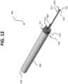
- tissue cutting device 500shown in FIGS. 11-20 .
- tissue cutting device 500can be used to cut any desired soft tissue structure in the body (e.g., of a human or non-human mammal).
- soft tissue structureincludes but is not limited to, a ligament, fascia, or tendon.
- the tissue cutting device 500is used to cut an A1 pulley.
- cutting device 500has a handle 600, a first blade 700, and a second blade 800.
- the first blade 700extends away from the handle 600.
- the second blade 800is coupled to and extends outwardly from the handle 600.
- the second blade 800is screwed to the handle 600.
- the handle 600 and the second blade 800can have screw holes 640, 803 formed therein for connecting the second blade 800 to the handle 600.
- any conventional fastenerincluding but not limited to, screws, glue or other adhesive, can be used to couple the second blade 800 to the handle 600.
- the handle 600preferably has an ergonomic design configured to facilitate holding of the device 500.
- the handle 600, the first blade 700, and the second blade 800 of cutting device 500can have any desired size suitable for performing a particular cutting procedure.
- the handle 600can be formed of any desired medically acceptable material.
- the first blade 700is similar to the first blade 200 of device 10.
- the first blade 700is configured to facilitate introduction of the tissue cutting device 500 through the dermis and into subcutaneous tissue of a patient.
- the first blade 700eliminates the need for the use of a separate, additional device to introduce the tissue cutting device 500 into the skin.
- the tissue cutting device 500has both the first blade 700 to introduce the device 500 into the skin, and the second blade 800 that can be unexposed and protected until needed to cut or release the tissue of interest.
- the first blade 700has a shaft 702.
- the shaft 702includes a distal end 705 provided on an outer surface of the first blade 700.
- the distal end 705 of the first blade 700includes one or more cutting surfaces.
- the distal end 705 of the first blade 700defines a blunt tip that is not intended for cutting tissue.
- the configuration of the distal end 705 of the first blade 700is not particularly limited.
- the distal end 705 of the first blade 700can include a pointed tip, a curved edge, a straight edge of uniform length, an angled surface that is longer on one side than on the other, or can have any other desired configuration.
- the one or more cutting surfaces of the first blade 700can extend along the entire outer surface of the first blade 700, along a major length of the outer surface (i.e., greater than 50% of a length of the outer surface) of the first blade 700, or along only a minor portion of the outer surface of the first blade 700, such as only at the distal end 705 of the outer surface of the first blade 700.
- the second blade 800is similar to the second blade 300 of device 10 and has a cutting surface 815.
- the cutting surface 815 of the second blade 800is less sharp than the cutting surface and/or distal end 705 of the first blade 700.
- the cutting surface 815 of the second blade 800is sharper than some (or all) of outer surface of the first blade 700.
- the cutting surface 815 of the second blade 800has the same sharpness as the outer surface (or as the cutting surface) of the first blade 700.
- the configuration of the cutting surface 815 of the second blade 800is also not limited. As shown, the cutting surface 815 can be a curved surface, a straight surface (or uniform length), an angled surface that is longer on one side than on the other side (e.g., a downward-angled cutting surface). In addition, the cutting surface 815 can face toward or away from the handle 600, or can face toward either side of the tissue cutting device 500. In some cases, the cutting surface 815 is provided on an interior surface of the second blade 800. In other cases, the cutting surface 815 is provided on an outer surface of the second blade 800 (e.g., so as to provide a superficial cutting surface).
- the cutting surface 815 of the second blade 800is a retrograde cutting surface configured to facilitate cutting of tissue when the second blade 800 is moved in a retrograde manner. In other cases, the cutting surface 815 of the second blade 800 is an antegrade cutting surface configured to facilitate cutting of tissue when the second blade 800 is moved in an antegrade manner. Skilled artisans will understand that the examples identified herein are not limiting, and that any type of cutting surface can be used as cutting surface 815.
- the second blade 800can have any desired number of cutting surfaces 815, each having any desired configuration. In some cases, the second blade 800 is provided with a single cutting surface 815. In other cases, the second blade 800 has more than one cutting surface 815 to allow the tissue cutting device 500 to achieve cuts in multiple directions.
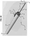
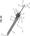
- the second blade 800is rotatable relative to the first blade 700 such that the second blade 800 is configured to rotate between a first (inactive) position 805 ( FIGS. 11 , 18 , and 19 ) and a second (active) position 810 ( FIGS. 12 and 20 ).
- the second blade 800is in a same plane as the first blade 700 when the second blade 800 is in the first position 805.
- the second blade 800is in a different plane from the first blade 700 when the second blade 800 is rotated from the first position 805 toward the second position 810. This can be appreciated by comparing FIG. 11 with FIG. 12 .
- FIGS. 11 , 18 and 19show that both the first blade 700 and the second blade 800 lie flat (i.e., parallel or substantially parallel) relative to each other when the second blade 800 is in the first position 805.
- This arrangement of the tissue cutting device 500provides a low-profile design that enables the tissue cutting device 500 to be inserted into tight spaces underneath a patient's skin, adjacent a desired tissue region.
- the second blade 800is rotated into a different plane from the first blade 700 as the second blade 800 is rotated from the first position 805 toward the second position 810.
- the second blade 800is an unexposed blade that is protected from contacting tissue.
- the second blade 800can remain in the first position 805 until needed for a cutting procedure.
- the second blade 800is rotated into the second (active) position 810, thereby becoming an exposed blade.
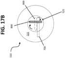
- the first blade 700is in contact (e.g., direct physical contact) with the second blade 800 when the second blade 800 is in the first position 805.
- This configurationis shown schematically in FIG. 17B .
- the shaft 702 of the first blade 700has a recessed area (not shown) in an upper surface 704 thereof configured to receive the shaft 802 of the second blade 800.
- This arrangementallows the second blade 800 to be recessed into the first blade 700.
- the depth of the recessed area in the shaft 702 of the first blade 700is variable such that the extent to which the first blade 700 is recessed into the second blade 800 is also variable.
- the recessed area in the shaft 702 of the first blade 700can be an imprint formed in any conventional manner, e.g., by stamping.
- the first blade 700is entirely recessed within the second blade 800 when the second blade 800 is in the first position 805. In such cases, when the second blade 800 is rotated from the first position 805 toward the second position 810, at least a portion of the second blade 800 rotates out of the recessed area of the first blade 700. In other cases, the shaft 702 of the first blade 700 does not include a recessed area. Instead, the second blade 800 is positioned so as to lie on top of, and directly contact, the upper surface 704 of the first blade 700.
- first blade 700 and the second blade 800are not in direct contact when the second blade 800 is in the first position 805 such that a gap is formed between the first 700 and second 800 blades.
- tissuemay become trapped within the gap, it is preferable that the gap (where present) be as small as possible.
- the tissue cutting device 500is hingeless.
- the material properties and designincluding the shape of device 500, as well as the thickness and flexibility of the second blade 800) allow the second blade 800 to intrinsically bend relative to the first blade 700.
- This optional hingeless feature of device 500is similar to certain hingeless embodiments of device 10.
- the tissue cutting device 500includes a hinge. Any type of conventional mechanical hinge can be used in tissue cutting device 500 to allow second blade 800 to rotate between its first 805 and second 810 positions.
- the second blade 800is provided with a virtual hinge, such as a seam that extends along a longitudinal axis of the second blade 800.
- the seamextends along the second blade 800 at a point where the second blade 800 is materially coupled to the first blade 200 such that the seam is provided at a junction of the first blade 700 and the second blade 800.
- the second blade 800can be thinner in the region where the seam is located so as to reduce resistance of the second blade 800 to bending. In this manner, the seam facilitates folding and bending of the second blade 800 along its longitudinal axis for rotating the second blade 800 from its first position 805 toward its second position 810.
- the second blade 800rotates between the first position 805 and the second position 810 in response to rotation of the handle 600.
- the first blade 700is configured to remain stationary or substantially stationary when the second blade 800 rotates from the first position 805 toward the second position 810.
- the second blade 800is configured to rotate along its longitudinal axis when the second blade 800 rotates between the first position 805 and the second position 810.
- the second blade 800can have any desired degree of rotation as needed to suit a particular cutting procedure. In some instances, the second blade 800 is configured to rotate in a range of between 0 and 360 degrees, including any degree therebetween. In other cases, the second blade 800 is configured to rotate in a range of between 0 and 180 degrees, including any degree therebetween. In still other cases, the second blade 800 is configured to rotate in a range of between 0 and 90 degrees, including any degree therebetween. In certain embodiments, the degree of rotation of the second blade 800 can be adjustable. Such adjustability can advantageously help account for anatomic variations between patients.
- the handle 600defines a housing having an interior surface 626.
- the handle 600comprises a single-piece structure.
- the handle 600comprises multiple sections, such as a first section 622 and a second section 624 that are coupled (e.g., molded) together.
- the interior surface 626 of the handle 600has a recess 630 formed therein.
- the recess 630is sized and shaped such that the recess 630 is configured to receive a shaft 802 of the second blade 800.
- the recess 630is formed in at least one of the first section 122 and the second section 124 (and in some cases, both sections) of the handle 600.
- the coupling of the second blade 800 and the handle 600ensures that the handle 600 and the second blade 800 rotate together.
- the handle 600has an interior 604.
- the interior 604 of the handle 600includes vertical side walls 606 and a medial wall 608 coupled to and extending horizontally between at least two of the vertical side walls 606.
- the vertical side walls 606 and the medial wall 608define a chamber 610 within the interior 604 of the handle 600.
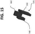
- the tissue cutting device 500further comprises a lock 860 ( FIGS. 13 , 14 , and 15 ).
- the lock 860has a locked configuration and an unlocked configuration.
- the lock 860is in the unlocked configuration, the second blade 800 is rotatable from the first position 805 toward the second position 810.
- the lock 860is configured to restrain the second blade 800 from rotating relative to the first blade 700.
- the second blade 800is locked in the first position 805 when the lock 860 is in the locked configuration.
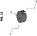
- the tissue cutting device 500also includes a cover 510.
- the cover 510is coupled to an upper end 605 of the handle 600.
- the handle 600is rotatable relative to the cover 510 to permit the second blade 800 to rotate from the first position 805 toward the second position 810.
- the handle 600is rotatable relative to the cover 510 when the lock 860 is in the unlocked configuration, whereas the handle 600 is restrained from rotating relative to the cover 510 when the lock 860 is in the locked configuration.
- the cover 510has a notch 512 formed therein (e.g., in a side surface thereof).
- the lock 860is received in the notch 512 when the lock 860 is in the locked configuration. Then, the lock 860 can be disengaged from the notch 512 when the operator desires to cut a desired tissue. This in turn disengages the cover 510 from the handle 600 and allows the handle 600 to rotate relative to the cover 510.
- the cover 510 and the handle 600are connected via snap fit notches that allow free rotation of the handle 600 relative to the cover 510 when the lock 860 is in the unlocked configuration.
- the cover 510includes more than one notch 512.
- the cover 510can include any desired number of notches 512. Multiple notches 512 allow the operator to control axial rotation of the second blade 800 within a specified range (i.e., between adjacent notches 512) that is dictated by the notches 512.
- the cover 510can include four notches 512, each spaced equally apart about a perimeter of the cover 510. In this non-limiting example, by rotating the second blade 800 between one or more adjacently positioned notches 512, the operator is able to lock the second blade 800 in place after rotating the second blade 800 exactly 90 degrees, exactly 180 degrees, exactly 270 degrees, or exactly 360 degrees.
- a top end 515 of the cover 510has both a first opening 520 and a second opening 525 formed therein.
- the first opening 520is configured to receive the first blade 700.
- the second opening 525is configured to receive the second blade 800.
- the first blade 700is mounted within a slot defined by the first opening 520. In some cases, the first blade 700 is glued within the slot. This, however, is by no means required. For instance, the first blade 700 can be mounted in the slot of the first opening 520 in any conventional manner.
- the first opening 520is laterally offset from the second opening 525 so as to arrange the blades 700, 800 in an L-shaped configuration. This arrangement, which is shown in FIG. 17A , helps prevent the entrapment of tissue, and allows the second blade 800 to rotate without interference from the first blade 700. In other cases, the first opening 520 is centered between opposite sides of the cover 510, such that the first 700 and second 800 blades are arranged in a T-shaped configuration.
- the tissue cutting device 500also includes a biasing member 530.
- the biasing member 530is positionable within the interior 604 of the handle 600, particularly within the chamber 610.
- the biasing member 530is operably coupled to the lock 860 so as to resiliently bias the lock 860 into the locked configuration.
- the biasing member 530merely biases the handle 600 toward the cover 510.
- the biasing member 530is a spring.
- tissue cutting device 500further include a projection 540.
- the projection 540is attached to the lock 860.
- the projection 540is also positionable within the interior 604 of the handle 600, particularly within the chamber 610.
- the biasing member 530is configured to urge against the projection 540 so as to provide upward force to the lock 860 to retain the lock 860 in the locked configuration.
- the projection 540is also configured to apply a counterforce to the biasing member 530 (so as to compress the biasing member 530) when the lock 860 is moved from the locked configuration to the unlocked configuration.
- the lock 860(whether in the locked or unlocked configuration) is positioned nearer to the cover 510 than is the projection 540.
- the tissue cutting device 500includes an actuator 550.
- the actuator 550is coupled to the lock 860 and is configured to move the lock 860 between the locked and unlocked configurations.
- the handle 600has a slot 602 formed in an outer surface 603 thereof.
- the actuator 550is slidably mounted in the slot 602 and is movable between a first position and a second position (e.g., using the operator's thumb or other finger). Slidable movement of the actuator 550 between its first and second positions causes the lock 860 to move between its locked and unlocked configurations.
- the actuator 550is in the first position
- the lock 860is in the locked configuration.
- the actuator 550is in the second position
- the lock 860is in the unlocked configuration.
- the lock 860is received in the notch 512 of the cover 510, the notch 512 is aligned with the slot 602.
- the lock 860is positioned between the projection 540 and the actuator 550.
- the lock 860 and the projection 540can be vertically aligned with respect to each other and each coupled to the actuator 550.
- the operatorpulls the actuator 550 toward a bottom end 680 of the handle 600 (i.e., a proximal end of the device 500). This in turn causes the lock 860 to be pulled away from (and out of) the notch 512. Thus, the actuator 550 can be pulled to disengage the lock 860, thus allowing the second blade 800 to rotate from the first position 805 toward the second position 810.
- An outer surface 570 of the actuator 550can optionally comprise a material, or include surface features, configured to facilitate gripping of the actuator 550.
- the outer surface 570 of the actuator 550comprises rubber or another suitable gripping material.
- the outer surface 570 of the actuator 550can include surface features, such as textured ridges, to facilitate sliding of the actuator 550 between its first and second positions.
- the cover 510is devoid of an actuator 550 and notches 512, and instead is merely activated by friction.
- the tissue cutting device 500can include at least one tooth (e.g., a plurality of teeth) or any high-friction surface (e.g., rubber).
- the teeth or high friction surface of device 500are configured to restrain the handle 600 from rotating relative to the cover 510 such that the handle 600, when rotated, can be locked into any position along a 360 degree arc about the cover 510.
- the teeth (or high-friction surface)can be provided on the cover 510, on the handle 600, or on both the handle 600 and the cover 510.
- the handle 600is restrained from rotating relative to the cover 510 when the teeth (or high-friction surface) are in contact with an adjacent surface of the handle 600.
- the handle 600is restrained from rotating relative to the cover 510 when the teeth (or high-friction surface) are in contact with an adjacent surface of the cover 510.
- the handle 600is pulled away from the cover 510 to compress the biasing member 530.
- the handle 600can then be rotated any desired degree relative to the cover 510 to rotate the second blade 300 any desired degree from the first position 805 toward the second position 810.
- tissue cutting device 10 and tissue cutting device 500are not limited to the particular dimensions shown, but instead, can have any dimensions needed to suit a particular cutting procedure. For instance, a width and/or length of the first blade 200, 700, the second blade 300, 800, the handle 100, 600, and/or the housing 120 can be varied as desired.
- the present disclosurealso provides an exemplary method, not forming part of the invention, of using the cutting devices 10, 500 to cut the soft tissue (e.g., ligament, fascia, or tendon) of a patient.
- the present disclosureprovides a method of performing an A1 pulley release procedure to treat trigger finger.
- the present methodscan be used to cut any soft tissue structure.
- the method of the present disclosureincludes the steps of (a) providing a soft tissue cutting device 10, 500; (b) advancing the tissue cutting device 10, 500 to a body region; (c) rotating the second blade 300, 800 from the first position 305, 805 to the second position 310, 810; and (d) cutting soft tissue in the body region using the second blade 300, 800 when the second blade 300, 800 is in the second position 310, 810.
- tissue cutting device 10 or 500can be used.
- the step of advancing the tissue cutting device 10, 500 to the body regioninvolves using the first blade 200, 700 to introduce the tissue cutting device 10, 500 into the body region.
- the methodincludes applying anesthetic to the patient's skin. Thereafter, the device 10, 500 is placed through and into the patient's skin adjacent a desired tissue plane. In some cases, the device 10, 500 is placed deep to the desired tissue plane such that the tissue to be cut is positioned above the cutting device 10, 500. However, the exact positioning of the device 10, 500 will depend on the configuration of the first blade 200, 700 and the second blade 300, 800, as well as on the type of cutting procedure to be performed.
- a small incisionis made in the patient's skin.
- this incisioncan be made by using the first blade 200, 700 where the outer surface of the first blade 200, 700 includes a cutting blade.
- a separate devicei.e., a device other than device 10 or 500 is used to make the incision.
- the first blade 200, 700is then placed into subcutaneous tissue of the patient such that the outer surface of the first blade 200, 700 is adjacent a desired tissue plane. Preferably, this placement is performed under ultrasound guidance.
- the second blade 300, 800remains in the first position 305, 805.
- the handle 100, 600is rotated to cause the second blade 300, 800 to rotate from its first position 305, 805 toward its second position 310, 810 so as to become an exposed blade.
- a cutting surface 315, 815 of the second blade 300, 800is then used to cut the tissue in a customary manner.
- the manner of cutting using the second blade 300, 800will vary depending on the particular type of cutting surface 315, 815, and its location on the second blade 300, 800.
- the second blade 300, 800may need to be pushed or pulled to cut the tissue. Once the tissue is cut, the device 10, 500 is pulled out of the incision to complete the surgical procedure. The device 10, 500 can optionally be discarded after use.
- Use of the device 900 having embodiments shown in FIG. 21may include steps in addition to those noted above.
- the flanges 425, 430help prevent the operator from inserting the device 900 too far into the body region.
- an operatorcan apply rotational force to the second blade 300 (for example by rotating the handle 100) to cause the break point 450 to disrupt, thereby separating the first blade 200 from the second blade 300.
- the first blade 200 and the second blade 300thereby become separate devices.
- the operatorcan then freely move and rotate the second blade 300 to perform cutting.
- the operatorcan grasp the handle 100 and pull the second blade 300 to remove it from the body region.
- the first blade 200can remain in the body until after the second blade 300 is removed.
- the operatorcan then grasp the flanges 425, 430 of the first blade 200 with fingers and then pull the first blade 200 to remove it from the body region.
- use of device 500may include steps in addition to those noted above.
- the operatorcan slide the actuator 550 from the first position to the second position to disengage the lock 860 from the notch 512.
- the operatorthen rotates the handle 600 to rotate the second blade 800 from the first position 805 toward the second position 810.
- Cutting of the tissue of intereste.g., the A1 pulley
- the handle 600is merely pulled away from the cover 510 to compress the biasing member 530, and the handle 600 is then rotated any desired degree relative to the cover 510.
- the methodis an A1 pulley release procedure for treating trigger finger.
- the distal end 205, 705 of the first blade 200, 700is placed deep to (i.e., below) the A1 pulley and superficial to (i.e., above) the flexor tendon group.
- the device 10, 500is initially flat (i.e., parallel to the patient's hand) and placed distal to proximal to the A1 pulley such that the distal end 205, 705 of the first blade 200, 700 faces toward the patient's wrist.
- the device 10, 500is properly positioned when the first blade 200, 700 is located above the tendon, the second blade 300, 800 is located above the first blade 200, 700 and below the A1 pulley, and the patient's skin is located above the A1 pulley.
- the handle 100, 600is rotated so as to rotate the second blade 300, 800 from its first position 305, 805 toward its second position 310, 810. This rotation exposes the second blade 300, 800 to the A1 pulley.
- the second blade 300, 800is then used to cut the A1 pulley, for example, by moving the second blade 300, 800 in a retrograde manner (i.e., proximal to distal) against the A1 pulley.
Landscapes
- Health & Medical Sciences (AREA)
- Surgery (AREA)
- Life Sciences & Earth Sciences (AREA)
- Biomedical Technology (AREA)
- Nuclear Medicine, Radiotherapy & Molecular Imaging (AREA)
- Engineering & Computer Science (AREA)
- Heart & Thoracic Surgery (AREA)
- Medical Informatics (AREA)
- Molecular Biology (AREA)
- Animal Behavior & Ethology (AREA)
- General Health & Medical Sciences (AREA)
- Public Health (AREA)
- Veterinary Medicine (AREA)
- Orthopedic Medicine & Surgery (AREA)
- Surgical Instruments (AREA)
Description
- The present invention relates generally to a micro-invasive surgical device. More specifically, the present invention relates to a micro-invasive tissue cutting device having a first blade and a second blade, wherein the second blade is rotatable relative to the first blade.
- The first annular ("A1") pulley is a small band of tissue on the palmar side of a person's hand. In some cases, the flexor tendon thickens and a nodule can get caught on the A1 pulley and cause irritation. The flexor tendon can then become locked in place when a person flexes his or her fingers. This condition is commonly referred to as "trigger finger." To treat trigger finger, the A1 pulley is typically cut so as to release the tendon. For this purpose, certain devices are known that use a hook blade to perform such a procedure. However, a hook blade tends to slide off the tendon. Moreover, with such conventional devices, an additional, separate device is often required to introduce the hook blade into the person's skin.
- As set forth in the present disclosure, it would be desirable to provide a tissue cutting device having a first blade and a second blade, wherein the second blade is rotatable relative to the first blade. In some cases, it would be desirable to provide such a device where the first blade facilitates introducing the tissue cutting device into and through a patient's skin. It would also be desirable to provide a second blade that is protected by the first blade until the second blade is deployed for a cutting procedure. Additionally, it would be desirable to provide a tissue cutting device that is minimally invasive and that can be used to treat trigger finger. Still further, it would be desirable to provide a tissue cutting device having a lock for selectively controlling rotation of the second blade relative to the first blade.
US 2017/042565 A1 ,US 2012/029543 A1 andEP 3278749 A1 provide examples of micro-invasive cutting devices of the prior art. - Claim 1 defines the invention and dependent claims disclose embodiments, No surgical methods form part of the invention. The invention provides a tissue cutting device comprising a handle, a first blade, and a second blade. The first blade and the second blade are coupled to the handle. The second blade comprises a cutting surface. Rotation of the handle causes the second blade to rotate from a first position in which the second blade lies in a same plane as the first blade to a second position, in which the second blade lies in a different plane than the first blade. The handle and the second blade comprise a single integrated structure. The tissue cutting device further comprises a break point positioned between the first blade and the handle. Rotating the second blade from the first position to the second position breaks the break point and separates the first blade from the handle..
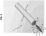
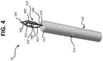
Figure 1 is a top perspective view of a tissue cutting device showing a handle coupled to a housing and a second blade in a first (inactive) position.Figure 2 is another top perspective view of the tissue cutting device ofFIG. 1 , showing the second blade in the first position.Figure 3 is a side perspective view of the tissue cutting device ofFIG. 1 , showing the first blade and the second blade lying in the same plane when the second blade is in the first position.Figure 4 is a top perspective of a tissue cutting device showing a handle coupled to a housing and a second blade in a second (active) position.Figure 5 is another top perspective view of the tissue cutting device ofFIG. 4 , showing the second blade in the second position.Figure 6 is a side view of a tissue cutting device showing a second blade in a second (active) position.Figure 7 is a schematic top perspective view of a tissue cutting device.Figure 8 is a schematic top perspective view of a tissue cutting device.Figure 9 is a top perspective view of a tissue cutting device.Figure 10 is an exploded view of a tissue cutting device showing a blade assembly separated from a handle.Figure 11 is a top perspective view of a tissue cutting device showing a second blade in a first (inactive) position.Figure 12 is a top perspective view of the tissue cutting device ofFIG. 11 , with both an actuator and a lock of the tissue cutting device removed, and showing the second blade in a second (active) position.Figure 13 is an exploded view of the tissue cutting device ofFIG. 11 .Figure 14 is another exploded view of the tissue cutting device ofFIG. 11 .Figure 15 is a side perspective view of a lock, an actuator, and a projection of a tissue cutting device in accordance with certain embodiments of the present disclosure.Figure 16 is a top perspective view of a cover of a tissue cutting device.Figure 17A is a top schematic view of a cover.Figure 17B is a top schematic view of a cover, schematically showing rotation of the second blade between the first and second positions, with the second blade resting on the first blade when the second blade is in the first position.Figure 18 is a top perspective view of the tissue cutting device ofFIG. 11 , with a top end of the cover removed, and the second blade in the first position.Figure 19 is a top perspective view of the cutting device ofFIG. 11 , with a portion of the cover removed and showing the second blade in the first position.Figure 20 is a top perspective view of the cutting device ofFIG. 11 , with a portion of the handle removed, and showing the second blade in the second position.Figure 21 is a schematic top perspective view of a tissue cutting device having a break point, in accordance with the invention.- The following detailed description is to be read with reference to the drawings, in which like elements in different drawings have like reference numerals. The drawings, which are not necessarily to scale, depict selected embodiments and are not intended to limit the scope of the invention. Skilled artisans will recognize that the examples provided herein have many useful alternatives that fall within the scope of the invention as defined by the claims.
- Referring to the drawings, and in particular,
FIGS. 1-10 , there is shown a tissue cutting device of the present disclosure generally represented byreference numeral 10. Thetissue cutting device 10 can be used to cut any desired soft tissue structure in the body (e.g., of a human or non-human mammal). Such soft tissue structure includes, but is not limited to, a ligament, fascia, or tendon. In certain preferred embodiments, thetissue cutting device 10 is used to cut an A1 pulley. - The
tissue cutting device 10 includes ahandle 100, afirst blade 200, and asecond blade 300 that collectively define a blade assembly. Thefirst blade 200 is coupled to thesecond blade 300 and bothblades handle 100. Thefirst blade 200 is an exposed blade. As used in the present disclosure, an exposed blade refers to a blade that is not protected from contact with tissue. In contrast, an unexposed blade, as used in the present disclosure, refers to a blade that is protected from coming into contact with tissue by another structure of thedevice 10. Thehandle 100, thefirst blade 200, and thesecond blade 300 can have any desired size suitable for performing a particular cutting procedure. In addition, thehandle 100 can be formed of any desired medically acceptable material. - As shown in
FIGS. 1-5 and10 , thetissue cutting device 10 can optionally include ahousing 120. In embodiments of this nature, thehandle 100 is coupled to thehousing 120 and extends outwardly (e.g., from a top end) of thehousing 120. Thehandle 100 can be either permanently or removably coupled to thehousing 120. Any conventional fastener can be used to couple thehandle 100 to thehousing 120, including but not limited to, screws, glue, or the like.FIGS. 1-5 and10 show a non-limiting example of an embodiment where thehandle 100 is screwed to thehousing 120 via screws inserted into screw holes 121, 123. - In certain cases, the
handle 100 is positionable within thehousing 120. In other embodiments, thehandle 100 is coupled to an exterior surface (e.g., top surface) of thehousing 120 and does not extend into any portion of thehousing 120. However, ahousing 120 is not required in all cases, and it is envisioned that thehousing 120 can be omitted in certain embodiments. In any embodiment of the present disclosure that includes thehousing 120, it is preferred that thehousing 120 has an ergonomic design configured to facilitate holding of thedevice 10. - Where the
housing 120 is provided, thehousing 120 can comprise a single-piece structure. In other instances, thehousing 120 comprises multiple sections (FIG. 10 ), such as afirst section 122 and asecond section 124 that are coupled together. Thesections housing 120 can be fixedly or removably coupled together. Thesesections housing 120, and such alternative fasteners will be readily apparent to skilled artisans. - In some embodiments, an
interior surface 126 of thehousing 120 has arecess 130 formed therein. As can be appreciated by referring toFIG. 10 , therecess 130 is sized and shaped such that therecess 130 is configured to receive thehandle 100 when thehandle 100 is coupled to thehousing 120. Where thehousing 120 includes thefirst section 122 and thesecond section 124, therecess 130 is formed in at least one of thefirst section 122 and the second section 124 (and optionally, both sections) of thehousing 120. In certain other embodiments, thehousing 120 does not include arecess 130. - In preferred embodiments, the
second blade 300 and thehandle 100 are integral structures. In some cases, thehandle 100, thefirst blade 200, and thesecond blade 300 are all integral structures. In still further embodiments, the entiretissue cutting device 10 can be a single integral structure so as to define a unibody construction. In such instances, for example, theentire device 10 can comprise a single piece of metal (e.g., surgical grade stainless steel), plastic, or any other suitable material. In addition, thetissue cutting device 10 can be manufactured by any conventional process. As non-limiting examples, thetissue cutting device 10 can be stamped or laser cut. - Advantageously, the
second blade 300 is rotatable relative to thefirst blade 200 such that thesecond blade 300 is configured to rotate between a first (inactive) position 305 (FIGS. 1-3 and7-10 ) and a second (active) position 310 (FIGS. 4-6 ). Thesecond blade 300 is in a same plane as thefirst blade 200 when thesecond blade 300 is in thefirst position 305. This is perhaps best illustrated inFig. 3 , which shows that thefirst blade 200 and thesecond blade 300 lie flat (i.e., parallel or substantially parallel) relative to each other when thesecond blade 300 is in thefirst position 305. This arrangement of thetissue cutting device 10 provides a low-profile design that enables thetissue cutting device 10 to be inserted into tight spaces underneath a patient's skin, adjacent a desired tissue region. - The
second blade 300 is rotated into a different plane from thefirst blade 200 as thesecond blade 300 is rotated from thefirst position 305 toward thesecond position 310. As described in greater detail below, when thesecond blade 300 is in the first (inactive)position 305, thesecond blade 300 is an unexposed blade that is protected (at least in part) by thefirst blade 200. Thesecond blade 300 can remain in thefirst position 305 until needed for a cutting procedure. Then, when it is desired to cut tissue using thesecond blade 300, thesecond blade 300 is rotated into the second (active)position 310, thereby becoming an exposed blade. - In certain embodiments, the
tissue cutting device 10 is hingeless. In such embodiments, as shown inFIGS. 1-10 , the material properties and design (including the shape ofdevice 10, as well as the thickness and flexibility of the second blade 300) allow thesecond blade 300 to intrinsically bend relative to thefirst blade 200. Thesecond blade 300 should be thin enough to allow thesecond blade 300 to bend to permit its rotation between the first 305 and second 310 positions. Thesecond blade 300 is capable of being bent in a manner that is similar to bending of a paper clip (i.e., whereby twisting an inner portion of a metal paper clip allows the inner portion to be rotated and positioned outside of an outer portion of the paper clip). - In other embodiments, the
tissue cutting device 10 includes a hinge. Any type of conventional mechanical hinge can be used intissue cutting device 10 to allowsecond blade 300 to rotate between its first 305 and second 310 positions. In other cases, thesecond blade 300 is provided with a virtual hinge, such as a seam that extends along a longitudinal axis of thesecond blade 300. In such instances, the seam extends along thesecond blade 300 at a point where thesecond blade 300 is materially coupled to thefirst blade 200 such that the seam is provided at ajunction 250 of thefirst blade 200 and thesecond blade 300. Thesecond blade 300 can be thinner in the region where the seam is located so as to reduce resistance of thesecond blade 300 to bending. In this manner, the seam facilitates folding and bending of thesecond blade 300 along its longitudinal axis for rotating thesecond blade 300 from itsfirst position 305 toward itssecond position 310. Thus, the seam allows thesecond blade 300 to move from itsfirst position 305 toward itssecond position 310 without separating thefirst blade 200 from thesecond blade 300. - The
second blade 300 rotates between thefirst position 305 and thesecond position 310 in response to rotation of thehandle 100. Thus, thesecond blade 300 and thehandle 100 rotate together. Thefirst blade 200 is configured to remain stationary or substantially stationary when thesecond blade 300 rotates from thefirst position 305 toward thesecond position 310. Thesecond blade 300 is configured to rotate along its longitudinal axis when thesecond blade 300 rotates between thefirst position 305 and thesecond position 310. In preferred embodiments, thehandle 100 is aligned (or substantially aligned) with the longitudinal axis of thesecond blade 300 such that thesecond blade 300 defines a linear extension of thehandle 100. - The
second blade 300 can have any desired degree of rotation as needed to suit a particular cutting procedure. In some instances, thesecond blade 300 is configured to rotate in a range of between 0 to 180 degrees, including any degree therebetween. In other cases, thesecond blade 300 is configured to rotate in a range of between 0 and 90 degrees (including any degree therebetween). - The
first blade 200 is configured to facilitate introduction of thetissue cutting device 10 through the dermis and into subcutaneous tissue of a patient. In this manner, thefirst blade 200 eliminates the need for the use of a separate, additional device to introduce thetissue cutting device 10 into the skin. Instead, thetissue cutting device 10 has both thefirst blade 200 to introduce thedevice 10 into the skin, and thesecond blade 300 that can be unexposed and protected until needed to cut or release the tissue of interest. - The
first blade 200 has adistal end 205. In some cases, the outer surface of thefirst blade 200 includes one or more cutting surfaces. In other cases, thedistal end 205 of thefirst blade 200 defines a tip intended for cutting tissue. For example, in certain cases, thedistal end 205 defines a blunt tip (e.g., a rounded, convex end) not intended for cutting tissue. In other cases, thedistal end 205 defines a tip intended for cutting tissue. For example, in some cases, thedistal end 205 defines a dissecting tip or a cutting tip. The configuration of thedistal end 205 of thefirst blade 200 is not particularly limited. For instance, thedistal end 205 of thefirst blade 200 can include a pointed tip (FIG. 7 ), a curved edge (FIG. 8 andFIG. 21 ), a straight edge of uniform length, an angled surface that is longer on one side than on the other, or can have any other desired configuration. In addition, the one or more cutting surfaces of thefirst blade 200 can extend along the entire outer surface of thefirst blade 200, along a major length of the outer surface of the first blade 200 (i.e., along a length that is greater than 50% of a length of the outer surface), or along only a minor portion of the outer surface of thefirst blade 200, such as only at thedistal end 205. - The
second blade 300 also has at least onecutting surface 315. In some embodiments, the cuttingsurface 315 of thesecond blade 300 is less sharp than the cutting surface and/ordistal end 205 of thefirst blade 200. In other cases, the cuttingsurface 315 of thesecond blade 300 is sharper than some (or all) of the outer surface of thefirst blade 200. In still yet other cases, the cuttingsurface 315 of thesecond blade 300 has the same sharpness as the outer surface (or as the cutting surface) of thefirst blade 200. - The configuration of the cutting
surface 315 of thesecond blade 300 is also not limited. The cuttingsurface 315 can be a single cutting surface or one of many cutting surfaces. Also the cuttingsurface 315 can be a curved surface, a straight surface (of uniform length), or an angled surface that is longer on one side than on the other side (e.g., a downward-angled cutting surface). In addition, the cuttingsurface 315 can face toward or away from thehandle 100, or can face toward either side of thetissue cutting device 10. In some cases, the cuttingsurface 315 is provided on an interior surface of thesecond blade 300. In other cases, the cuttingsurface 315 is provided on an outer surface of the second blade 300 (e.g., so as to provide a superficial cutting surface). In certain embodiments, the cuttingsurface 315 of thesecond blade 300 is a retrograde cutting surface configured to facilitate cutting of tissue when thesecond blade 300 is moved in a retrograde manner. In other cases, the cuttingsurface 315 of thesecond blade 300 is an antegrade cutting surface configured to facilitate cutting of tissue when thesecond blade 300 is moved in an antegrade manner. In yet other cases, the cuttingsurface 315 is both a retrograde and antegrade cutting surface. Skilled artisans will understand that the examples identified herein are not limiting, and that any type of cutting surface can be used as cuttingsurface 315. - Although only one
cutting surface 315 is shown in the drawings, thesecond blade 300 can have any desired number of cuttingsurfaces 315, each having any desired configuration. In some cases, thesecond blade 300 is provided with asingle cutting surface 315. In other cases, thesecond blade 300 has more than onecutting surface 315 to allow thetissue cutting device 10 to achieve cuts in multiple directions. - The
tissue cutting device 10 further includes afirst arm 400 and asecond arm 405. Thefirst arm 400 and thesecond arm 405 define opposite sides of thefirst blade 200. Thefirst arm 400 is coupled to and extends between thefirst blade 200 and afirst side 105 of thehandle 100. In preferred embodiments, thefirst arm 400 is coupled directly to thehandle 100. Thesecond arm 405 is coupled to thefirst blade 200 and extends from thefirst blade 200 toward asecond side 110 of thehandle 100. However, unlike thefirst arm 400, thesecond arm 405 does not contact any portion of the handle 100 (or the second blade 300). This space between thesecond arm 405 relative to both thehandle 100 and thesecond blade 300 defines agap 415. As described in greater detail below, thesecond arm 405 is configured to stabilize the tissue cutting device 10 (particularly thefirst blade 200 and the first arm 400) when thesecond blade 300 is rotated from thefirst position 305 to thesecond position 310. In particular, thegap 415 allows only a portion of the tissue cutting device to rotate (i.e., thehandle 100 and the second blade 300), while a remainder of thedevice 10 is configured to remain stationary or substantially stationary. - When the
second blade 300 is in thefirst position 305, the cuttingsurface 315 of thesecond blade 300 is positioned between (e.g., directly between) thehandle 100 and thefirst blade 200. In more detail, thesecond blade 300 is located between thehandle 100, thefirst blade 200, thefirst arm 400, and thesecond arm 405 when thesecond blade 300 is in thefirst position 305. Thus, thehandle 100, thefirst blade 200, thefirst arm 400, and thesecond arm 405 define anouter enclosure 410 surrounding thesecond blade 300 when thesecond blade 300 is in thefirst position 305. Thisouter enclosure 410 protects thesecond blade 300 from contacting tissue when thesecond blade 300 is in thefirst position 305. - The
second blade 300 is configured to rotate outside of theouter enclosure 410 when thesecond blade 300 is rotated from thefirst position 305 toward thesecond position 310. Rotation to thesecond position 310 allows thesecond blade 300 to be exposed for cutting tissue, since thesecond blade 300 is no longer protected by theouter enclosure 410. In some cases, as shown inFIGS. 1-10 , theouter enclosure 410 has a convex or substantially convex shape. However, alternative configurations for theouter enclosure 410 are also contemplated and within the scope of the present disclosure. - As the
second blade 300 rotates from thefirst position 305 toward thesecond position 310, thesecond arm 405 does not rotate (or at least remains stationary or substantially stationary). This is at least in part due to a greater surface area of thesecond arm 405 as compared to a surface area of thesecond blade 300. In particular, thesecond blade 300 is thin enough to rotate when introduced subcutaneously into the skin near a tissue region of interest. Thesecond arm 405, on the other hand, is held down by the tissue or other structure to be cut and therefore is restrained from rotating when thesecond blade 300 rotates from thefirst position 305 toward thesecond position 310. - In some cases, at least one
tooth 420 is coupled to aninterior surface 425 of at least one of thefirst arm 400 and thesecond arm 405. In some cases, the at least onetooth 420 includes two or more teeth or a plurality of teeth. The at least onetooth 420 can be coupled to the only thefirst arm 400, only thesecond arm 405, or to both thefirst arm 400 and thesecond arm 405. The at least onetooth 420 is perhaps best shown inFIGS. 7 and8 , where it is depicted as two teeth. The at least onetooth 420 is configured to embed into the undersurface of the structure to be cut (e.g., the A1 pulley) to ensure that thedevice 10 will not slide during use. The cuttingsurface 315 of thesecond blade 300 can extend outwardly toward thesecond arm 405 such that the at least onetooth 420 is positioned on an arm that is nearest the cuttingsurface 315. - Another exemplary embodiment of a
tissue cutting device 900 is shown inFIG. 21 . Thetissue cutting device 900 ofFIG. 21 can optionally include any of the features previously described forFIGS. 1-10 . This embodiment includes afirst blade 200 and asecond blade 300 and further includes abreak point 450 between thefirst blade 200 and thehandle 100. Thebreak point 450 is configured to be disrupted. Thebreak point 450 allows an operator to disrupt thebreak point 450 and separate thefirst blade 200 from thesecond blade 300. When thebreak point 450 is intact, thesecond blade 300 is in itsfirst position 305. When force is applied to thebreak point 450 to separate thefirst blade 200 from thesecond blade 300, thesecond blade 300 assumes itssecond position 310. - Generally, the
first blade 200 is coupled to thehandle 100 via thebreak point 450, which is configured to break thefirst blade 200 away from thehandle 100. Thesecond blade 300 is also coupled to thehandle 100 but does not include a break point. In other words, thesecond blade 300 is configured to remain connected to thehandle 100 and does not break away from thehandle 100. In some cases, thesecond blade 300 is integral to thehandle 100. Thebreak point 450 allows an operator to break away or separate thefirst blade 200 from thehandle 100, thus separating thefirst blade 200 from thesecond blade 300 and handle 100. In certain cases, thebreak point 450 is configured to be disrupted when the second blade is rotated from thefirst position 305 toward thesecond position 310. - Referring to
FIG. 21 , certain embodiments include afirst blade 200 that includes adistal end 205 and aproximal end 210. Thefirst blade 200 extends for a length "X" along its longitudinal axis from thedistal end 205 to theproximal end 210. Thefirst blade 200 also includes afirst arm 400 and asecond arm 405. Thefirst arm 400 and thesecond arm 405 define opposite sides of thefirst blade 200. Each thefirst arm 400 and thesecond arm 405 extend along the longitudinal axis between thedistal end 205 and aproximal end 210. - The
first arm 400 is coupled to thehandle 100 at thebreak point 450. Thesecond arm 405 is not coupled to thehandle 100. Rather, thesecond arm 405 does not contact any portion of thehandle 100. Agap 415 is provided between thesecond arm 405 and thehandle 100. Thebreak point 450 can be provided anywhere along thefirst arm 400. In certain cases, thebreak point 450 is positioned on thefirst arm 400 such that it is adjacent to theproximal end 210. - The
break point 450 is configured to break thefirst arm 400 from thehandle 100 upon force. In other words, an operator applies force to thebreak point 450 to disrupt it and therefore separate the first arm 400 (and thus the first blade 200) from the handle 100 (and thus the second blade 300). Thebreak point 450 can include any mechanism that allows force to break away thefirst arm 400 from thehandle 100. In certain cases, thebreak point 450 is formed as a break-away seam. In other cases, thebreak point 450 is formed as a break away hinge. Such a break-away seam or hinge can include snap perforations or frangible bridges that allow force to break away thefirst arm 400 from thehandle 100. - In certain embodiments, an operator uses rotational force to break away the
first arm 400 from thehandle 100. For example, an operator rotates thehandle 100 in either a clockwise or counterclockwise direction to disrupt thebreak point 450. In other embodiments, an operator uses a pushing or pulling force. Any number of break away mechanisms are contemplated. - Some embodiments also provide one or more flanges that extend outward from the
first blade 200. The one or more flanges are sized and shaped to accommodate an operator's fingers. An operator can grasp the one or more flanges to assist in manipulating thefirst blade 200. In certain cases, the one or more flanges extend radially outward from the longitudinal axis of thefirst blade 200. In some cases, the one or more flanges extend generally perpendicular from the longitudinal axis of thefirst blade 200. In some cases, the one or more flanges are provided as a first flange and a second flange. The first flange and second flange can extend outward as a pair of wings, similar to flanges of a medical syringe. In other cases, the one or more flanges are provided as a single circular flange that surrounds thefirst blade 200. A variety of different types of flanges are contemplated. - In the embodiment of
FIG. 21 , thefirst blade 200 includes afirst flange 425 and asecond flange 430. Thefirst flange 425 extends from thefirst arm 400 and thesecond flange 430 extends from thesecond arm 405. Also, thefirst flange 425 extends radially outward from thefirst arm 400 and from the longitudinal axis of thefirst blade 200, and thesecond flange 430 extends radially outward from thesecond arm 405 and from the longitudinal axis of thefirst blade 200. In some cases, thefirst flange 425 and thesecond flange 430 can each extend generally perpendicular to the longitudinal axis, although this is not required. - As shown in
FIG. 21 , both thefirst flange 425 and thesecond flange 430 are positioned near aproximal end 210 of thefirst blade 200. Thefirst blade 200 is also provided with a length "X," which is the length between thedistal end 205 and theproximal end 210. The length "X" is selected to be a maximum length of where thefirst blade 200 should be inserted into the body. Thefirst flange 425 and thesecond flange 430 therefore prevent thefirst blade 200 from being inserted beyond the selected maximum length and therefore prevent it from being inserted too deeply into the body. Theflanges handle 100,first blade 200 and second blade 300) before separation of thefirst blade 200 from thehandle 100. - Once the
first blade 200 is separated from thehandle 100, an operator can move thesecond blade 300 independently of thefirst blade 200. In some cases, an operator can rotate thesecond blade 300 in a range of between 0 to 360 degrees. Any desired movement is possible since thesecond blade 300 is independent of thefirst blade 200. An operator then uses thehandle 100 to manipulate thesecond blade 300 to perform the desired cutting. Once cutting is completed, the operator pulls thehandle 100 and thus thesecond blade 300 out of the body. Theflanges first blade 200 after separation from thesecond blade 300. For example, an operator can grasp theflanges first blade 200 out of the body. - Although certain embodiments describing a
break point 450 have been described, in some cases, thebreak point 450 shown inFIG. 21 is omitted and replaced with a hinge. In such cases, the hinge is provided in a location where thebreak point 450 would otherwise be located. In such instances, the hinge enables thesecond blade 300 to rotate relative to thefirst blade 200, but does not allow thefirst blade 200 to be separated from thesecond blade 300. In other words, thefirst blade 200 is configured to remain connected to thehandle 100 and does not break away from the handle 100 (such that thefirst blade 200 and thesecond blade 300 also remain connected). In embodiments of this nature, any type of conventional mechanical hinge can be used to allowsecond blade 300 to rotate between its first 305 and second 310 positions. In other cases, a virtual hinge, such as a seam, is provided. In such instances, the seam extends along thefirst blade 200 at a point where thefirst blade 200 is materially coupled to thehandle 100. In embodiments where a hinge is provided, thesecond blade 300 is able to rotate relative to thefirst blade 200 in a similar manner to the other hinge embodiments described herein (e.g. by rotating the handle 100). - The present disclosure also provides
tissue cutting device 500, shown inFIGS. 11-20 . As withtissue cutting device 10,tissue cutting device 500 can be used to cut any desired soft tissue structure in the body (e.g., of a human or non-human mammal). Such soft tissue structure includes but is not limited to, a ligament, fascia, or tendon. In certain embodiments, thetissue cutting device 500 is used to cut an A1 pulley. - Similar to cutting
device 10, cuttingdevice 500 has ahandle 600, afirst blade 700, and asecond blade 800. Thefirst blade 700 extends away from thehandle 600. Thesecond blade 800 is coupled to and extends outwardly from thehandle 600. In some cases, thesecond blade 800 is screwed to thehandle 600. For example, as shown inFIGS. 13 and14 , thehandle 600 and thesecond blade 800 can havescrew holes second blade 800 to thehandle 600. However, it will be appreciated that any conventional fastener, including but not limited to, screws, glue or other adhesive, can be used to couple thesecond blade 800 to thehandle 600. Furthermore, thehandle 600 preferably has an ergonomic design configured to facilitate holding of thedevice 500. - Similar to cutting
device 10, thehandle 600, thefirst blade 700, and thesecond blade 800 of cuttingdevice 500 can have any desired size suitable for performing a particular cutting procedure. In addition, thehandle 600 can be formed of any desired medically acceptable material. - The
first blade 700 is similar to thefirst blade 200 ofdevice 10. In particular, thefirst blade 700 is configured to facilitate introduction of thetissue cutting device 500 through the dermis and into subcutaneous tissue of a patient. In this manner, thefirst blade 700 eliminates the need for the use of a separate, additional device to introduce thetissue cutting device 500 into the skin. Instead, thetissue cutting device 500 has both thefirst blade 700 to introduce thedevice 500 into the skin, and thesecond blade 800 that can be unexposed and protected until needed to cut or release the tissue of interest. - The
first blade 700 has ashaft 702. Theshaft 702 includes adistal end 705 provided on an outer surface of thefirst blade 700. In some cases, thedistal end 705 of thefirst blade 700 includes one or more cutting surfaces. In other cases, thedistal end 705 of thefirst blade 700 defines a blunt tip that is not intended for cutting tissue. The configuration of thedistal end 705 of thefirst blade 700 is not particularly limited. For instance, thedistal end 705 of thefirst blade 700 can include a pointed tip, a curved edge, a straight edge of uniform length, an angled surface that is longer on one side than on the other, or can have any other desired configuration. In addition, the one or more cutting surfaces of thefirst blade 700 can extend along the entire outer surface of thefirst blade 700, along a major length of the outer surface (i.e., greater than 50% of a length of the outer surface) of thefirst blade 700, or along only a minor portion of the outer surface of thefirst blade 700, such as only at thedistal end 705 of the outer surface of thefirst blade 700. - The
second blade 800 is similar to thesecond blade 300 ofdevice 10 and has a cuttingsurface 815. In some embodiments, the cuttingsurface 815 of thesecond blade 800 is less sharp than the cutting surface and/ordistal end 705 of thefirst blade 700. In other cases, the cuttingsurface 815 of thesecond blade 800 is sharper than some (or all) of outer surface of thefirst blade 700. In still yet other cases, the cuttingsurface 815 of thesecond blade 800 has the same sharpness as the outer surface (or as the cutting surface) of thefirst blade 700. - The configuration of the cutting
surface 815 of thesecond blade 800 is also not limited. As shown, the cuttingsurface 815 can be a curved surface, a straight surface (or uniform length), an angled surface that is longer on one side than on the other side (e.g., a downward-angled cutting surface). In addition, the cuttingsurface 815 can face toward or away from thehandle 600, or can face toward either side of thetissue cutting device 500. In some cases, the cuttingsurface 815 is provided on an interior surface of thesecond blade 800. In other cases, the cuttingsurface 815 is provided on an outer surface of the second blade 800 (e.g., so as to provide a superficial cutting surface). In certain embodiments, the cuttingsurface 815 of thesecond blade 800 is a retrograde cutting surface configured to facilitate cutting of tissue when thesecond blade 800 is moved in a retrograde manner. In other cases, the cuttingsurface 815 of thesecond blade 800 is an antegrade cutting surface configured to facilitate cutting of tissue when thesecond blade 800 is moved in an antegrade manner. Skilled artisans will understand that the examples identified herein are not limiting, and that any type of cutting surface can be used as cuttingsurface 815. - Although only one
cutting surface 815 is shown in the drawings, thesecond blade 800 can have any desired number of cuttingsurfaces 815, each having any desired configuration. In some cases, thesecond blade 800 is provided with asingle cutting surface 815. In other cases, thesecond blade 800 has more than onecutting surface 815 to allow thetissue cutting device 500 to achieve cuts in multiple directions. - The
second blade 800 is rotatable relative to thefirst blade 700 such that thesecond blade 800 is configured to rotate between a first (inactive) position 805 (FIGS. 11 ,18 , and19 ) and a second (active) position 810 (FIGS. 12 and20 ). Thesecond blade 800 is in a same plane as thefirst blade 700 when thesecond blade 800 is in thefirst position 805. Thesecond blade 800 is in a different plane from thefirst blade 700 when thesecond blade 800 is rotated from thefirst position 805 toward thesecond position 810. This can be appreciated by comparingFIG. 11 withFIG. 12 . FIGS. 11 ,18 and19 show that both thefirst blade 700 and thesecond blade 800 lie flat (i.e., parallel or substantially parallel) relative to each other when thesecond blade 800 is in thefirst position 805. This arrangement of thetissue cutting device 500 provides a low-profile design that enables thetissue cutting device 500 to be inserted into tight spaces underneath a patient's skin, adjacent a desired tissue region.- The
second blade 800 is rotated into a different plane from thefirst blade 700 as thesecond blade 800 is rotated from thefirst position 805 toward thesecond position 810. As described in greater detail below, when thesecond blade 800 is in the first (inactive)position 805, thesecond blade 800 is an unexposed blade that is protected from contacting tissue. Thesecond blade 800 can remain in thefirst position 805 until needed for a cutting procedure. Then, when it is desired to cut tissue using thesecond blade 800, thesecond blade 800 is rotated into the second (active)position 810, thereby becoming an exposed blade. - In preferred embodiments, the
first blade 700 is in contact (e.g., direct physical contact) with thesecond blade 800 when thesecond blade 800 is in thefirst position 805. This configuration is shown schematically inFIG. 17B . In some cases, theshaft 702 of thefirst blade 700 has a recessed area (not shown) in anupper surface 704 thereof configured to receive theshaft 802 of thesecond blade 800. This arrangement allows thesecond blade 800 to be recessed into thefirst blade 700. The depth of the recessed area in theshaft 702 of thefirst blade 700 is variable such that the extent to which thefirst blade 700 is recessed into thesecond blade 800 is also variable. The recessed area in theshaft 702 of thefirst blade 700 can be an imprint formed in any conventional manner, e.g., by stamping. In certain embodiments, thefirst blade 700 is entirely recessed within thesecond blade 800 when thesecond blade 800 is in thefirst position 805. In such cases, when thesecond blade 800 is rotated from thefirst position 805 toward thesecond position 810, at least a portion of thesecond blade 800 rotates out of the recessed area of thefirst blade 700. In other cases, theshaft 702 of thefirst blade 700 does not include a recessed area. Instead, thesecond blade 800 is positioned so as to lie on top of, and directly contact, theupper surface 704 of thefirst blade 700. - In still yet other cases, the
first blade 700 and thesecond blade 800 are not in direct contact when thesecond blade 800 is in thefirst position 805 such that a gap is formed between the first 700 and second 800 blades. However, since tissue may become trapped within the gap, it is preferable that the gap (where present) be as small as possible. - In certain embodiments, the
tissue cutting device 500 is hingeless. In such embodiments, as shown inFIGS. 11-20 , the material properties and design (including the shape ofdevice 500, as well as the thickness and flexibility of the second blade 800) allow thesecond blade 800 to intrinsically bend relative to thefirst blade 700. This optional hingeless feature ofdevice 500 is similar to certain hingeless embodiments ofdevice 10. - In other embodiments, the
tissue cutting device 500 includes a hinge. Any type of conventional mechanical hinge can be used intissue cutting device 500 to allowsecond blade 800 to rotate between its first 805 and second 810 positions. In other cases, thesecond blade 800 is provided with a virtual hinge, such as a seam that extends along a longitudinal axis of thesecond blade 800. In such instances, the seam extends along thesecond blade 800 at a point where thesecond blade 800 is materially coupled to thefirst blade 200 such that the seam is provided at a junction of thefirst blade 700 and thesecond blade 800. Thesecond blade 800 can be thinner in the region where the seam is located so as to reduce resistance of thesecond blade 800 to bending. In this manner, the seam facilitates folding and bending of thesecond blade 800 along its longitudinal axis for rotating thesecond blade 800 from itsfirst position 805 toward itssecond position 810. - The
second blade 800 rotates between thefirst position 805 and thesecond position 810 in response to rotation of thehandle 600. Thus, thesecond blade 800 and thehandle 600 rotate together. Thefirst blade 700 is configured to remain stationary or substantially stationary when thesecond blade 800 rotates from thefirst position 805 toward thesecond position 810. Thesecond blade 800 is configured to rotate along its longitudinal axis when thesecond blade 800 rotates between thefirst position 805 and thesecond position 810. - The
second blade 800 can have any desired degree of rotation as needed to suit a particular cutting procedure. In some instances, thesecond blade 800 is configured to rotate in a range of between 0 and 360 degrees, including any degree therebetween. In other cases, thesecond blade 800 is configured to rotate in a range of between 0 and 180 degrees, including any degree therebetween. In still other cases, thesecond blade 800 is configured to rotate in a range of between 0 and 90 degrees, including any degree therebetween. In certain embodiments, the degree of rotation of thesecond blade 800 can be adjustable. Such adjustability can advantageously help account for anatomic variations between patients. - The
handle 600 defines a housing having aninterior surface 626. In some cases, thehandle 600 comprises a single-piece structure. In other instances, thehandle 600 comprises multiple sections, such as afirst section 622 and asecond section 624 that are coupled (e.g., molded) together. In some embodiments, theinterior surface 626 of thehandle 600 has arecess 630 formed therein. Therecess 630 is sized and shaped such that therecess 630 is configured to receive ashaft 802 of thesecond blade 800. Where thehandle 600 includes thefirst section 622 and thesecond section 624, therecess 630 is formed in at least one of thefirst section 122 and the second section 124 (and in some cases, both sections) of thehandle 600. The coupling of thesecond blade 800 and thehandle 600 ensures that thehandle 600 and thesecond blade 800 rotate together. - The
handle 600 has an interior 604. In some cases, theinterior 604 of thehandle 600 includesvertical side walls 606 and amedial wall 608 coupled to and extending horizontally between at least two of thevertical side walls 606. Thevertical side walls 606 and themedial wall 608 define achamber 610 within theinterior 604 of thehandle 600. - In certain embodiments, the
tissue cutting device 500 further comprises a lock 860 (FIGS. 13 ,14 , and15 ). Thelock 860 has a locked configuration and an unlocked configuration. When thelock 860 is in the unlocked configuration, thesecond blade 800 is rotatable from thefirst position 805 toward thesecond position 810. When thelock 860 is in the locked configuration, thelock 860 is configured to restrain thesecond blade 800 from rotating relative to thefirst blade 700. Thesecond blade 800 is locked in thefirst position 805 when thelock 860 is in the locked configuration. - The
tissue cutting device 500 also includes acover 510. Thecover 510 is coupled to anupper end 605 of thehandle 600. Thehandle 600 is rotatable relative to thecover 510 to permit thesecond blade 800 to rotate from thefirst position 805 toward thesecond position 810. In embodiments that include thelock 860, thehandle 600 is rotatable relative to thecover 510 when thelock 860 is in the unlocked configuration, whereas thehandle 600 is restrained from rotating relative to thecover 510 when thelock 860 is in the locked configuration. - In certain embodiments, the
cover 510 has anotch 512 formed therein (e.g., in a side surface thereof). Thelock 860 is received in thenotch 512 when thelock 860 is in the locked configuration. Then, thelock 860 can be disengaged from thenotch 512 when the operator desires to cut a desired tissue. This in turn disengages thecover 510 from thehandle 600 and allows thehandle 600 to rotate relative to thecover 510. In some cases, thecover 510 and thehandle 600 are connected via snap fit notches that allow free rotation of thehandle 600 relative to thecover 510 when thelock 860 is in the unlocked configuration. - In certain embodiments (not shown), the
cover 510 includes more than onenotch 512. Thecover 510 can include any desired number ofnotches 512.Multiple notches 512 allow the operator to control axial rotation of thesecond blade 800 within a specified range (i.e., between adjacent notches 512) that is dictated by thenotches 512. For example, thecover 510 can include fournotches 512, each spaced equally apart about a perimeter of thecover 510. In this non-limiting example, by rotating thesecond blade 800 between one or more adjacently positionednotches 512, the operator is able to lock thesecond blade 800 in place after rotating thesecond blade 800 exactly 90 degrees, exactly 180 degrees, exactly 270 degrees, or exactly 360 degrees. - A
top end 515 of thecover 510 has both afirst opening 520 and asecond opening 525 formed therein. Thefirst opening 520 is configured to receive thefirst blade 700. Thesecond opening 525 is configured to receive thesecond blade 800. In certain preferred embodiments, thefirst blade 700 is mounted within a slot defined by thefirst opening 520. In some cases, thefirst blade 700 is glued within the slot. This, however, is by no means required. For instance, thefirst blade 700 can be mounted in the slot of thefirst opening 520 in any conventional manner. - In preferred embodiments, the
first opening 520 is laterally offset from thesecond opening 525 so as to arrange theblades FIG. 17A , helps prevent the entrapment of tissue, and allows thesecond blade 800 to rotate without interference from thefirst blade 700. In other cases, thefirst opening 520 is centered between opposite sides of thecover 510, such that the first 700 and second 800 blades are arranged in a T-shaped configuration. - The
tissue cutting device 500 also includes a biasingmember 530. The biasingmember 530 is positionable within theinterior 604 of thehandle 600, particularly within thechamber 610. In certain embodiments, the biasingmember 530 is operably coupled to thelock 860 so as to resiliently bias thelock 860 into the locked configuration. In other cases (e.g., in embodiments where there is no lock 860), the biasingmember 530 merely biases thehandle 600 toward thecover 510. In some embodiments, as shown inFIGS. 13 ,14 , and20 , the biasingmember 530 is a spring. - Certain embodiments of the
tissue cutting device 500 further include aprojection 540. Theprojection 540 is attached to thelock 860. Theprojection 540 is also positionable within theinterior 604 of thehandle 600, particularly within thechamber 610. When in an uncompressed state, the biasingmember 530 is configured to urge against theprojection 540 so as to provide upward force to thelock 860 to retain thelock 860 in the locked configuration. Theprojection 540 is also configured to apply a counterforce to the biasing member 530 (so as to compress the biasing member 530) when thelock 860 is moved from the locked configuration to the unlocked configuration. In preferred cases, the lock 860 (whether in the locked or unlocked configuration) is positioned nearer to thecover 510 than is theprojection 540. - In some embodiments, the
tissue cutting device 500 includes anactuator 550. Theactuator 550 is coupled to thelock 860 and is configured to move thelock 860 between the locked and unlocked configurations. In certain embodiments, thehandle 600 has aslot 602 formed in anouter surface 603 thereof. Theactuator 550 is slidably mounted in theslot 602 and is movable between a first position and a second position (e.g., using the operator's thumb or other finger). Slidable movement of theactuator 550 between its first and second positions causes thelock 860 to move between its locked and unlocked configurations. In more detail, when theactuator 550 is in the first position, thelock 860 is in the locked configuration. When theactuator 550 is in the second position, thelock 860 is in the unlocked configuration. When thelock 860 is received in thenotch 512 of thecover 510, thenotch 512 is aligned with theslot 602. - In certain embodiments, the
lock 860 is positioned between theprojection 540 and theactuator 550. However, in alternative embodiments, thelock 860 and theprojection 540 can be vertically aligned with respect to each other and each coupled to theactuator 550. - In certain embodiments, to use
tissue cutting device 500, the operator pulls theactuator 550 toward abottom end 680 of the handle 600 (i.e., a proximal end of the device 500). This in turn causes thelock 860 to be pulled away from (and out of) thenotch 512. Thus, theactuator 550 can be pulled to disengage thelock 860, thus allowing thesecond blade 800 to rotate from thefirst position 805 toward thesecond position 810. - An
outer surface 570 of theactuator 550 can optionally comprise a material, or include surface features, configured to facilitate gripping of theactuator 550. For instance, in some embodiments, theouter surface 570 of theactuator 550 comprises rubber or another suitable gripping material. In addition or alternatively, theouter surface 570 of theactuator 550 can include surface features, such as textured ridges, to facilitate sliding of theactuator 550 between its first and second positions. - In alternative embodiments, the
cover 510 is devoid of anactuator 550 andnotches 512, and instead is merely activated by friction. In such cases, thetissue cutting device 500 can include at least one tooth (e.g., a plurality of teeth) or any high-friction surface (e.g., rubber). The teeth or high friction surface ofdevice 500 are configured to restrain thehandle 600 from rotating relative to thecover 510 such that thehandle 600, when rotated, can be locked into any position along a 360 degree arc about thecover 510. The teeth (or high-friction surface) can be provided on thecover 510, on thehandle 600, or on both thehandle 600 and thecover 510. Where the teeth (or high-friction surface) are provided on thecover 510, thehandle 600 is restrained from rotating relative to thecover 510 when the teeth (or high-friction surface) are in contact with an adjacent surface of thehandle 600. Where the teeth (or high-friction surface) are provided on thehandle 600, thehandle 600 is restrained from rotating relative to thecover 510 when the teeth (or high-friction surface) are in contact with an adjacent surface of thecover 510. In use, thehandle 600 is pulled away from thecover 510 to compress the biasingmember 530. Thehandle 600 can then be rotated any desired degree relative to thecover 510 to rotate thesecond blade 300 any desired degree from thefirst position 805 toward thesecond position 810. - The dimensions of
tissue cutting device 10 andtissue cutting device 500 are not limited to the particular dimensions shown, but instead, can have any dimensions needed to suit a particular cutting procedure. For instance, a width and/or length of thefirst blade second blade handle housing 120 can be varied as desired. - The present disclosure also provides an exemplary method, not forming part of the invention, of using the
cutting devices - Generally, the method of the present disclosure includes the steps of (a) providing a soft
tissue cutting device tissue cutting device second blade first position second position second blade second blade second position tissue cutting device tissue cutting device first blade tissue cutting device - In preferred embodiments, the method includes applying anesthetic to the patient's skin. Thereafter, the
device device device device first blade second blade - For the methods of the present disclosure, a small incision is made in the patient's skin. In some cases, this incision can be made by using the
first blade first blade first blade device 10 or 500) is used to make the incision. - The
first blade first blade device second blade first position handle second blade first position second position surface second blade second blade surface second blade second blade device device - Use of the
device 900 having embodiments shown inFIG. 21 may include steps in addition to those noted above. For example, when inserting thedevice 900, theflanges device 900 too far into the body region. Once thedevice 900 is poisoned, an operator can apply rotational force to the second blade 300 (for example by rotating the handle 100) to cause thebreak point 450 to disrupt, thereby separating thefirst blade 200 from thesecond blade 300. Thefirst blade 200 and thesecond blade 300 thereby become separate devices. The operator can then freely move and rotate thesecond blade 300 to perform cutting. After cutting, the operator can grasp thehandle 100 and pull thesecond blade 300 to remove it from the body region. Thefirst blade 200 can remain in the body until after thesecond blade 300 is removed. The operator can then grasp theflanges first blade 200 with fingers and then pull thefirst blade 200 to remove it from the body region. - Due to the presence of
actuator 550 in certain embodiments ofdevice 500, use ofdevice 500 may include steps in addition to those noted above. In particular, once the positioning ofdevice 500 is confirmed (e.g., under ultrasound), the operator can slide the actuator 550 from the first position to the second position to disengage thelock 860 from thenotch 512. The operator then rotates thehandle 600 to rotate thesecond blade 800 from thefirst position 805 toward thesecond position 810. Cutting of the tissue of interest (e.g., the A1 pulley) can then be performed by moving thesecond blade 800 in a conventional manner against the tissue. For embodiments that do not include theactuator 550 or notch(es) 512, thehandle 600 is merely pulled away from thecover 510 to compress the biasingmember 530, and thehandle 600 is then rotated any desired degree relative to thecover 510. - In some cases, the method is an A1 pulley release procedure for treating trigger finger. In such cases, the
distal end first blade device distal end first blade device first blade second blade first blade handle second blade first position second position second blade second blade second blade - For the above-described method, and with respect to
device 10 in particular, upward force from the tendon, as well as a counterforce from the A1 pulley, help keep thesecond arm 405 parallel to the plane of the A1 pulley while thesecond blade 300 rotates from thefirst position 305 to thesecond position 310. - While some preferred embodiments of the disclosure have been described, it should be understood that various changes, adaptations and modifications may be made therein without departing from the scope of the invention, which is defined solely by the appended claims.
Claims (15)
- A tissue cutting device (900) comprising:a handle (100);a first blade (200) coupled to the handle (100); anda second blade (300) coupled to the handle (100), the second blade (300) comprising a cutting surface (315), wherein rotation of the handle (100) causes the second blade (300) to rotate from a first position, in which the second blade (300) lies in a same plane as the first blade (200) to a second position, in which the second blade (300) lies in a different plane than the first blade (200),characterized in thatthe handle (100) and the second blade (300) comprise a single integral structure,the tissue cutting device (900) further comprising a break point (450) positioned between the first blade (200) and the handle (100), andin that rotating the second blade (300) from the first position to the second position breaks the break point and separates the first blade (200) from the handle (100).
- The tissue cutting device (900) of claim 1, wherein the break point (450) is formed as a seam that comprises snap perforations.
- The tissue cutting device (900) of claim 1, further comprising one or more flanges (425, 435) coupled to and extending outwardly from the first blade (200).
- The tissue cutting device (900) of claim 1, wherein the second blade (300) has a longitudinal axis, and wherein rotating the second blade (300) from the first position to the second position comprising rotating the second blade (300) along the longitudinal axis.
- The tissue cutting device (900) of claim 4, wherein the handle (100) is aligned with the longitudinal axis of the second blade (300) such that the second blade (300) defines a linear extension of the handle.
- The tissue cutting device (900) of claim 1, wherein the first blade (200) is configured to remain stationary when the second blade (300) rotates from the first position to the second position.
- The tissue cutting device (900) of claim 1, wherein the first blade (200) has a distal end (205) comprising a blunt tip.
- The tissue cutting device (900) of claim 1, wherein the first blade (200) has a distal end (205) comprising a cutting surface (315).
- The tissue cutting device (900) of claim 1, wherein the cutting surface (315) of the second blade (300) comprises a retrograde cutting surface or an anterograde cutting surface.
- The tissue cutting device (900) of claim 1, further comprising a first arm (400) and a second arm (405) that define opposite sides of the first blade (200), the first arm (400) being coupled to and extending between the first blade (200) and a first side of the handle (100), the second arm (405) being coupled to the first blade (200) and extending from the first blade (200) toward a second side of the handle (100), the second blade (300) being located between the handle (100), the first blade (200), the first arm (400), and the second arm (405) when the second blade (300) is in the first position, wherein the second blade (300) is configured to rotate outside of the outer enclosure when the second blade (300) is rotated to the second position.
- The tissue cutting device (900) of claim 10, wherein the outer enclosure has a convex shape.
- The tissue cutting device (900) of claim 10, further comprising at least one tooth (420) coupled to an interior surface of the second arm (405).
- The tissue cutting device (900) of claim 10, wherein a distal end of the second blade (300) extends outward toward the second arm (405).
- The tissue cutting device (900) of claim 1, wherein the tissue cutting device (900) does not include a hinge.
- The tissue cutting device (900) of claim 1, wherein the first blade (200) and the second blade (300) are sized and shaped to be advanced into a finger of a human patient, and wherein the second blade (300) is configured to cut a first annular pulley in the finger.
Applications Claiming Priority (3)
| Application Number | Priority Date | Filing Date | Title |
|---|---|---|---|
| US201962791269P | 2019-01-11 | 2019-01-11 | |
| US201962853930P | 2019-05-29 | 2019-05-29 | |
| PCT/US2020/012682WO2020146458A1 (en) | 2019-01-11 | 2020-01-08 | Micro-invasive surgical device and methods of use |
Publications (4)
| Publication Number | Publication Date |
|---|---|
| EP3908215A1 EP3908215A1 (en) | 2021-11-17 |
| EP3908215A4 EP3908215A4 (en) | 2022-03-23 |
| EP3908215B1true EP3908215B1 (en) | 2023-08-02 |
| EP3908215C0 EP3908215C0 (en) | 2023-08-02 |
Family
ID=71520482
Family Applications (1)
| Application Number | Title | Priority Date | Filing Date |
|---|---|---|---|
| EP20738258.1AActiveEP3908215B1 (en) | 2019-01-11 | 2020-01-08 | Micro-invasive surgical device |
Country Status (3)
| Country | Link |
|---|---|
| US (3) | US11937845B2 (en) |
| EP (1) | EP3908215B1 (en) |
| WO (1) | WO2020146458A1 (en) |
Families Citing this family (7)
| Publication number | Priority date | Publication date | Assignee | Title |
|---|---|---|---|---|
| WO2016044072A1 (en) | 2014-09-18 | 2016-03-24 | Mayo Foundation For Medical Education And Research | Soft tissue cutting device and methods of use |
| US10864055B2 (en) | 2017-10-13 | 2020-12-15 | Sonex Health, Inc. | Tray for a soft tissue cutting device and methods of use |
| EP3908215B1 (en) | 2019-01-11 | 2023-08-02 | Mayo Foundation for Medical Education and Research | Micro-invasive surgical device |
| US12426939B2 (en) | 2019-05-29 | 2025-09-30 | Mayo Foundation For Medical Education And Research | Micro-invasive surgical device and methods of use |
| WO2022150837A1 (en) | 2021-01-08 | 2022-07-14 | Sonex Health, Inc. | Surgical cutting device for ultrasonic guided soft tissue surgery |
| US12251122B2 (en) | 2021-04-30 | 2025-03-18 | Sonex Health, Inc. | Cutting device for trigger finger and other soft tissues |
| USD989961S1 (en) | 2021-04-30 | 2023-06-20 | Sonex Health, Inc. | Soft tissue cutting device |
Family Cites Families (222)
| Publication number | Priority date | Publication date | Assignee | Title |
|---|---|---|---|---|
| US1057867A (en) | 1912-10-07 | 1913-04-01 | John B Meadows | Fly-trap. |
| US2123768A (en) | 1936-06-18 | 1938-07-12 | Corsico-Piccolini Hector | Safety razor blade |
| US3435826A (en) | 1964-05-27 | 1969-04-01 | Edwards Lab Inc | Embolectomy catheter |
| US3448518A (en)* | 1967-07-27 | 1969-06-10 | Harry Sklar | Knife |
| US4610667A (en)* | 1984-05-11 | 1986-09-09 | Pedicano James J | Disposable safety needle sheath |
| US4979951A (en) | 1984-05-30 | 1990-12-25 | Simpson John B | Atherectomy device and method |
| US4963147A (en) | 1987-09-18 | 1990-10-16 | John M. Agee | Surgical instrument |
| US5089000A (en) | 1987-09-18 | 1992-02-18 | John M. Agee | Surgical method and instrument therefor |
| US4962770A (en) | 1987-09-18 | 1990-10-16 | John M. Agee | Surgical method |
| US5331975A (en) | 1990-03-02 | 1994-07-26 | Bonutti Peter M | Fluid operated retractors |
| US5345927A (en) | 1990-03-02 | 1994-09-13 | Bonutti Peter M | Arthroscopic retractors |
| US5954739A (en) | 1990-03-02 | 1999-09-21 | General Surgical Innovations, Inc. | Method of dissecting tissue layers |
| US5425355A (en) | 1991-01-28 | 1995-06-20 | Laserscope | Energy discharging surgical probe and surgical process having distal energy application without concomitant proximal movement |
| US5125927A (en)* | 1991-02-19 | 1992-06-30 | Belanger Neil F | Breakaway electrode for surgical cutting and cauterizing tool |
| US5217007A (en) | 1991-04-26 | 1993-06-08 | Cook Incorporated | Speculum for forming an ostomy in a trachea |
| ZA923086B (en) | 1991-04-29 | 1993-10-28 | South African Medical Research | A delivery system for biologicaly active growth or morphogenetic factors and a method for preparing such delivery system |
| US6361543B1 (en) | 1991-05-29 | 2002-03-26 | Sherwood Services Ag | Inflatable devices for separating layers of tissue, and methods of using |
| US7744617B2 (en) | 1991-05-29 | 2010-06-29 | Covidien Ag | Method and inflatable chamber apparatus for separating layers of tissue |
| US5865728A (en) | 1991-05-29 | 1999-02-02 | Origin Medsystems, Inc. | Method of using an endoscopic inflatable lifting apparatus to create an anatomic working space |
| US5325883A (en) | 1991-11-04 | 1994-07-05 | Orr Terrence R | Device and method for carpal tunnel release |
| US5655545A (en) | 1992-02-06 | 1997-08-12 | Johnson; Gerald W. | Dissection of tissue by tissue expander |
| US5306284A (en) | 1992-02-19 | 1994-04-26 | John Agee | Surgical instrument |
| US6312442B1 (en) | 1992-06-02 | 2001-11-06 | General Surgical Innovations, Inc. | Method for developing an anatomic space for laparoscopic hernia repair |
| US5540711A (en) | 1992-06-02 | 1996-07-30 | General Surgical Innovations, Inc. | Apparatus and method for developing an anatomic space for laparoscopic procedures with laparoscopic visualization |
| US5772680A (en) | 1992-06-02 | 1998-06-30 | General Surgical Innovations, Inc. | Apparatus and method for developing an anatomic space for laparoscopic procedures with laparoscopic visualization |
| US6540764B1 (en) | 1992-06-02 | 2003-04-01 | General Surgical Innovations, Inc. | Apparatus and method for dissecting tissue layers |
| US5620446A (en) | 1992-07-14 | 1997-04-15 | Endoscopic Heel Systems, Inc. | Surgical apparatus for performing endoscopic surgery at locations where tissue inserts into bone |
| US5569283A (en) | 1993-09-03 | 1996-10-29 | United States Surgical Corporation | Surgical cutting instrument with guarded blade |
| US5690664A (en) | 1993-09-13 | 1997-11-25 | United States Surgical Corporation | Trocar having movable blade |
| US5353812A (en) | 1993-10-12 | 1994-10-11 | Chow James C Y | Trigger finger release surgical method |
| US5480408A (en) | 1993-10-12 | 1996-01-02 | Chow; James C. Y. | Endoscopic surgical kit for release of trigger finger |
| US5620458A (en) | 1994-03-16 | 1997-04-15 | United States Surgical Corporation | Surgical instruments useful for endoscopic spinal procedures |
| US5690668A (en) | 1994-06-29 | 1997-11-25 | General Surgical Innovations, Inc. | Extraluminal balloon dissection |
| AU699844B2 (en) | 1994-08-25 | 1998-12-17 | Ethicon Endo-Surgery, Inc. | Safety trocar |
| US5547463A (en) | 1994-10-07 | 1996-08-20 | United States Surgical Corporation | Surgical hand support apparatus |
| US5782850A (en) | 1994-10-12 | 1998-07-21 | Ro; Man Tack | Method for treating trigger finger, and medical instrument therefor |
| DE4444166C2 (en) | 1994-12-12 | 1998-09-24 | Urotech Med Tech Gmbh | Flexible knife device for surgical purposes |
| US5649946A (en) | 1995-03-20 | 1997-07-22 | Bramlet; Dale G. | Carpal tunnel medical instrument |
| US5607441A (en) | 1995-03-24 | 1997-03-04 | Ethicon Endo-Surgery, Inc. | Surgical dissector |
| US5569300A (en) | 1995-04-12 | 1996-10-29 | Redmon; Henry A. | Dilating surgical forceps having illumination means on blade inner surface |
| US5702417A (en) | 1995-05-22 | 1997-12-30 | General Surgical Innovations, Inc. | Balloon loaded dissecting instruments |
| US7037317B2 (en) | 1995-05-22 | 2006-05-02 | United States Surgical Corporation | Balloon dissecting instruments |
| MX9601936A (en) | 1995-07-07 | 1997-01-31 | Becton Dickinson Co | An improved skin preparation tray for use in surgical procedures. |
| US6083177A (en) | 1995-09-14 | 2000-07-04 | Kobren; Myles S. | Cervical biopsy device and method |
| JP3736877B2 (en) | 1995-09-19 | 2006-01-18 | 義治 湯本 | Tendon sheath knife |
| US5957944A (en) | 1995-11-07 | 1999-09-28 | Biomet, Inc. | Method for treatment of trigger finger |
| BR9611737A (en)* | 1995-11-21 | 1999-02-23 | Harwill Ind Pty Ltd | Disposable scalpel |
| US5709697A (en) | 1995-11-22 | 1998-01-20 | United States Surgical Corporation | Apparatus and method for removing tissue |
| US5735865A (en) | 1995-12-19 | 1998-04-07 | Richard Wolf Gmbh | Instrument for endoscopic therapy |
| US5908433A (en) | 1996-05-10 | 1999-06-01 | Stryker Corporation | Carpal tunnel knife |
| US5766198A (en) | 1996-06-10 | 1998-06-16 | Li; Bing | Surgical knife employing a vacuum to ensure precise depth of incisions |
| US5810806A (en) | 1996-08-29 | 1998-09-22 | Ethicon Endo-Surgery | Methods and devices for collection of soft tissue |
| US6117153A (en) | 1996-10-03 | 2000-09-12 | Interventional Technologies, Inc. | Neovascularization catheter |
| US5769865A (en) | 1997-02-25 | 1998-06-23 | Surgical Insight, Inc. | Instrument and method for transection of a ligament |
| US5800449A (en) | 1997-03-11 | 1998-09-01 | Ethicon Endo-Surgery, Inc. | Knife shield for surgical instruments |
| US5827311A (en) | 1997-05-08 | 1998-10-27 | Biomet Inc | Carpal tunnel tome |
| US6015421A (en) | 1997-05-15 | 2000-01-18 | General Surgical Innovations, Inc. | Apparatus and method for developing an anatomic space for laparoscopic procedures |
| FR2764515B1 (en) | 1997-06-16 | 1999-09-03 | Sedat | BALLOON INFLATION DEVICE |
| NL1006944C2 (en) | 1997-09-04 | 1999-03-11 | Mark Hans Emanuel | Surgical endoscopic cutting device. |
| US6017356A (en) | 1997-09-19 | 2000-01-25 | Ethicon Endo-Surgery Inc. | Method for using a trocar for penetration and skin incision |
| US5904699A (en) | 1997-09-19 | 1999-05-18 | Ethicon Endo-Surgery, Inc. | Trocar for penetration and skin incision |
| US6012586A (en) | 1997-11-24 | 2000-01-11 | Maxxim Medical, Inc. | Medical procedure kit |
| US6875182B2 (en) | 1998-03-03 | 2005-04-05 | Senorx, Inc. | Electrosurgical specimen-collection system |
| US6758848B2 (en) | 1998-03-03 | 2004-07-06 | Senorx, Inc. | Apparatus and method for accessing a body site |
| US6030402A (en) | 1998-04-23 | 2000-02-29 | Thompson; Ronald J. | Apparatus and methods for the penetration of tissue, and the creation of an opening therein |
| US5968061A (en) | 1998-04-27 | 1999-10-19 | Theodor Esser | Endoscopic surgical instrument for the implementation of endoscopic surgical procedures |
| US6402770B1 (en) | 1998-06-01 | 2002-06-11 | Avatar Design & Development, Inc. | Method and apparatus for placing and maintaining a percutaneous tube into a body cavity |
| US6080175A (en) | 1998-07-29 | 2000-06-27 | Corvascular, Inc. | Surgical cutting instrument and method of use |
| US6007554A (en) | 1998-09-03 | 1999-12-28 | Van Ess; Lester Jay | Surgical cutter |
| US7329253B2 (en) | 2003-12-09 | 2008-02-12 | Rubicor Medical, Inc. | Suction sleeve and interventional devices having such a suction sleeve |
| US6099518A (en) | 1998-10-20 | 2000-08-08 | Boston Scientific Corporation | Needle herniorrhaphy devices |
| US6019774A (en) | 1998-12-10 | 2000-02-01 | Kinetikos Medical Incorporated | Carpal tunnel release apparatus and method |
| US6179852B1 (en) | 1999-02-01 | 2001-01-30 | Biomet, Inc. | Carpal tunnel device and method |
| AU3306500A (en) | 1999-03-19 | 2000-10-09 | Paul Cervi | Biopsy needle |
| US6592602B1 (en) | 1999-10-08 | 2003-07-15 | General Surgical Innovations, Inc. | Balloon dissection apparatus |
| US6358251B1 (en) | 2000-03-21 | 2002-03-19 | University Of Washington | Method and apparatus for forming a cavity in soft tissue or bone |
| US20020161387A1 (en) | 2000-06-22 | 2002-10-31 | Blanco Ernesto E. | Safety trocar with progressive cutting tip guards and gas jet tissue deflector |
| US6346085B1 (en) | 2000-06-27 | 2002-02-12 | Noah I. Schiffman | Soft tissue biopsy instrument |
| WO2002083021A1 (en) | 2001-04-13 | 2002-10-24 | I-Flow Corporation | Sterile container for medical applications |
| US6685717B1 (en) | 2001-08-15 | 2004-02-03 | Flovector, L.L.C. | Scalpel system for treating carpal tunnel syndrome |
| US6746465B2 (en) | 2001-12-14 | 2004-06-08 | The Regents Of The University Of California | Catheter based balloon for therapy modification and positioning of tissue |
| US6896141B2 (en) | 2002-02-28 | 2005-05-24 | Kimberly-Clark Worldwide, Inc. | Surgical kit with multiple planar recess surfaces |
| GB2385791B (en) | 2002-02-28 | 2005-03-30 | Alexander Craig Wille Campbell | Surgical device |
| US8105342B2 (en) | 2002-05-08 | 2012-01-31 | Apollo Endosurgery, Inc. | Apparatus for ligating/suturing living tissues and system for resecting/suturing living tissues |
| US20040143280A1 (en) | 2003-01-17 | 2004-07-22 | Loubert Suddaby | Flexible wire transection the transverse carpal ligament |
| US7481817B2 (en) | 2003-02-13 | 2009-01-27 | Lsi Soultions, Inc. | Instrument for surgically cutting tissue and method of use |
| US20040195131A1 (en) | 2003-04-03 | 2004-10-07 | Medical Components, Inc. | Snap tray for medical accessories |
| US8419728B2 (en) | 2003-06-30 | 2013-04-16 | Depuy Products, Inc. | Surgical scalpel and system particularly for use in a transverse carpal ligament surgical procedure |
| US8590764B2 (en) | 2003-12-24 | 2013-11-26 | Boston Scientific Scimed, Inc. | Circumferential full thickness resectioning device |
| US20050209624A1 (en) | 2004-03-22 | 2005-09-22 | Venkataramana Vijay | Scissors for piercing and cutting anatomical vessels |
| US20050222598A1 (en) | 2004-04-05 | 2005-10-06 | Manoa Medical, Inc., A Delaware Corporation | Tissue cutting device |
| US7708751B2 (en) | 2004-05-21 | 2010-05-04 | Ethicon Endo-Surgery, Inc. | MRI biopsy device |
| EP1616593B1 (en) | 2004-07-14 | 2008-08-27 | Terumo Kabushiki Kaisha | Package for medical tubes |
| US8613745B2 (en) | 2004-10-15 | 2013-12-24 | Baxano Surgical, Inc. | Methods, systems and devices for carpal tunnel release |
| US7331462B2 (en) | 2004-10-26 | 2008-02-19 | Alcon, Inc. | Kit management system |
| US20060149136A1 (en) | 2004-12-22 | 2006-07-06 | Kyphon Inc. | Elongating balloon device and method for soft tissue expansion |
| US7295057B2 (en) | 2005-01-18 | 2007-11-13 | International Business Machines Corporation | Methods and apparatus for characterizing electronic fuses used to personalize an integrated circuit |
| AU2006211174B2 (en) | 2005-01-27 | 2012-05-31 | Cook Medical Technologies Llc | Endoscopic cutting device |
| US20060190021A1 (en) | 2005-02-18 | 2006-08-24 | Michael Hausman | Cutting device for subcutaneous incisions |
| US8906040B2 (en) | 2005-07-13 | 2014-12-09 | Creighton University | Systems and techniques for minimally invasive gastrointestinal procedures |
| US7993359B1 (en) | 2005-07-27 | 2011-08-09 | The Spectrametics Corporation | Endocardial lead removing apparatus |
| US10433859B2 (en) | 2005-10-12 | 2019-10-08 | Atricure, Inc. | Diaphragm entry for posterior surgical access |
| EP1948045A2 (en) | 2005-11-10 | 2008-07-30 | T.A.G. Medical Products a Limited Partnership | Medical implement particularly useful in arthroscopic surgical procedures |
| US20070112366A1 (en) | 2005-11-14 | 2007-05-17 | Welborn Kenneth M | Apparatus and method for releasing tendon sheath |
| WO2007076463A2 (en) | 2005-12-27 | 2007-07-05 | Acist Medical Systems, Inc. | Balloon inflation device |
| US20070225740A1 (en) | 2006-02-22 | 2007-09-27 | Loubert Suddaby | Endoscopic Pulley Knife Instrument for Transecting Ligaments or Fascia |
| US20080033466A1 (en) | 2006-02-28 | 2008-02-07 | Trans1 Inc. | Surgical cutter with exchangeable cutter blades |
| US7731727B2 (en) | 2006-04-26 | 2010-06-08 | Lsi Solutions, Inc. | Medical instrument to place a pursestring suture, open a hole and pass a guidewire |
| US7780690B2 (en) | 2006-06-08 | 2010-08-24 | Recon Surgical, Inc. | Instruments and method for minimally invasive carpal tunnel release |
| US20110112563A1 (en) | 2006-06-30 | 2011-05-12 | Atheromed, Inc. | Atherectomy devices and methods |
| EP1875874B1 (en) | 2006-07-06 | 2013-02-27 | Covidien LP | Two mode trocar assembly |
| US20100010530A1 (en) | 2006-07-14 | 2010-01-14 | Ams Research Corporation | Balloon Dilation for Implantable Prosthesis |
| WO2008022087A2 (en) | 2006-08-11 | 2008-02-21 | Mynosys Cellular Devices, Inc. | Three-dimensional cutting instrument |
| US7918784B2 (en) | 2006-08-18 | 2011-04-05 | Microaire Surgical Instruments, Inc. | Endoscopic surgical tool with retractable blade for carpal tunnel release |
| US20080058846A1 (en) | 2006-08-31 | 2008-03-06 | Khashayar Vosough | Mechanical tissue morcellator |
| US20080109021A1 (en) | 2006-11-07 | 2008-05-08 | Medoff Robert J | Surgical tool with integral blade and self-centering tip |
| US8052710B2 (en) | 2006-12-15 | 2011-11-08 | Parviz Kambin | Endoscopic balloon tissue dissector and retractor |
| EP2126566B1 (en) | 2007-02-02 | 2017-03-29 | Albert Einstein College of Medicine, Inc. | Metastasis specific splice variants of mena and uses thereof in diagnosis, prognosis and treatment of tumors |
| US8992424B2 (en) | 2007-02-09 | 2015-03-31 | Skeletal Dynamics Llc | Endo-surgical device and method |
| US20080234713A1 (en) | 2007-03-19 | 2008-09-25 | Robert Bernardini | Shaver blade with depth markings |
| US8177064B2 (en) | 2007-04-20 | 2012-05-15 | Doheny Eye Institute | Surgical pack and tray |
| US7842056B2 (en) | 2007-05-18 | 2010-11-30 | Boston Scientific Scimed, Inc. | Cutting member for bifurcation catheter assembly |
| US20090048620A1 (en) | 2007-08-14 | 2009-02-19 | Illuminoss Medical, Inc. | Apparatus and methods for carpal tunnel release |
| US11191931B2 (en) | 2007-10-01 | 2021-12-07 | Pmt Partners, Llc | Methods for manually injecting/aspirating fluids through small diameter catheters and needles and manual injection/aspiration systems including small diameter catheters and needles |
| US8551129B2 (en) | 2007-11-14 | 2013-10-08 | Todd P. Lary | Treatment of coronary stenosis |
| WO2009076176A1 (en) | 2007-12-07 | 2009-06-18 | Edward Diao | Endoscopic system for accessing constrained surgical spaces |
| US8631935B2 (en) | 2009-06-03 | 2014-01-21 | Medline Industries, Inc. | Catheter tray, packaging system, and associated methods |
| CA2715895A1 (en) | 2008-02-20 | 2009-08-27 | Mayo Foundation For Medical Education And Research | Ultrasound guided systems and methods |
| US8202299B2 (en) | 2008-03-19 | 2012-06-19 | Collabcom II, LLC | Interspinous implant, tools and methods of implanting |
| US8252013B2 (en) | 2008-04-30 | 2012-08-28 | Kyphon Sarl | Expandable surgical access device and methods of use |
| US8449478B2 (en) | 2008-05-16 | 2013-05-28 | Conquest Medical Technologies | Biopsy device |
| US7967137B2 (en) | 2008-06-09 | 2011-06-28 | Fulbrook Jason D | Organizer of expendable supplies for medical patients (OESMP) |
| WO2009152470A1 (en) | 2008-06-13 | 2009-12-17 | The Foundry, Llc. | Methods and apparatus for joint distraction |
| US8579930B2 (en) | 2008-09-15 | 2013-11-12 | Del Palma Orthopedics, LLC | Surgical instrument and method of use for releasing soft tissue |
| US20100100114A1 (en) | 2008-10-20 | 2010-04-22 | Berger J Lee | Inflatable tissue elevator and expander |
| US20100125266A1 (en) | 2008-11-17 | 2010-05-20 | The Foundry, Llc | Methods and devices to treat compressive neuropathy and other diseases |
| US7628798B1 (en) | 2008-11-25 | 2009-12-08 | Microaire Surgical Instruments, Inc. | Hub and handle design for carpal tunnel release tool |
| US8523891B2 (en) | 2009-02-23 | 2013-09-03 | Microaire Surgical Instruments, Llc | Probe for carpal tunnel release tool or tissue dissection |
| US8911470B2 (en) | 2012-09-04 | 2014-12-16 | A.M. Surgical, Inc. | Compact endoscopic surgical blade assembly and method of use thereof |
| US11096710B2 (en) | 2012-09-04 | 2021-08-24 | A.M. Surgical, Inc. | Compact endoscopic surgical blade assembly and method of use thereof |
| US10492817B2 (en) | 2009-03-09 | 2019-12-03 | A.M. Surgical, Inc. | Endoscopic surgical blade and use thereof |
| US10849644B2 (en) | 2009-03-09 | 2020-12-01 | A.M. Surgical, Inc. | Surgical device |
| US9066746B2 (en) | 2012-09-04 | 2015-06-30 | A.M. Surgical, Inc. | Compact endoscopic surgical blade assembly and method of use thereof |
| US8827893B2 (en) | 2009-03-09 | 2014-09-09 | A. M. Surgical, Inc. | Slotted clear cannula |
| US8702654B2 (en) | 2009-03-25 | 2014-04-22 | John M. Agee | Treatment of carpal tunnel syndrome by injection of the flexor retinaculum |
| US8753364B2 (en) | 2009-08-07 | 2014-06-17 | Thayer Intellectual Property, Inc. | Systems and methods for treatment of compressed nerves |
| US8652157B2 (en) | 2009-08-07 | 2014-02-18 | Thayer Intellectual Property, Inc. | Systems and methods for treatment of compressed nerves |
| WO2011017665A2 (en) | 2009-08-07 | 2011-02-10 | Thayer Intellectual Property, Inc. | Systems and methods for treatment of compressed nerves |
| US8951273B1 (en) | 2009-09-25 | 2015-02-10 | Mike Fard | Surgical instrument for endoscopic surgical procedures |
| US20110087258A1 (en) | 2009-10-14 | 2011-04-14 | Sluss Robert K | Cannulated arthroscopic knife |
| US8608763B1 (en) | 2009-10-15 | 2013-12-17 | SonicSurg Innovations, LLC | Method for minimally invasive tendon sheath release |
| ES2874194T3 (en) | 2009-12-16 | 2021-11-04 | Boston Scient Scimed Inc | Arrangements for making an endoluminal anatomical structure |
| US9084593B2 (en) | 2009-12-27 | 2015-07-21 | Medline Industries, Inc. | Holding apparatus for medical implements |
| WO2011087462A1 (en) | 2010-01-14 | 2011-07-21 | Sunton Wongsiri | The surgical visual field enhancer apparatus and its method of use |
| US20110201881A1 (en) | 2010-02-16 | 2011-08-18 | Frederick Emch | Laser guided endoscopic surgical tool |
| SG184362A1 (en) | 2010-03-30 | 2012-11-29 | Singapore Health Serv Pte Ltd | Cutting device for cutting tissue |
| WO2011140206A1 (en) | 2010-05-04 | 2011-11-10 | The Ohio State University | Surgical device, method of performing surgery using same, and surgical device kit |
| US8672960B2 (en) | 2010-07-14 | 2014-03-18 | SEG-Way Orthopaedics, Inc | Method and apparatus for endoscopic ligament release |
| US9168057B2 (en) | 2010-07-15 | 2015-10-27 | Kebomed Ag | Surgical apparatus |
| US8273098B2 (en) | 2010-07-15 | 2012-09-25 | Del Palma Orthopedics, LLC | Carpal tunnel release tool |
| US20120029542A1 (en) | 2010-07-29 | 2012-02-02 | Chi-Yuen Huang | Micro-scalpel used to treat carpal tunnel syndrome |
| US8257379B2 (en) | 2010-07-29 | 2012-09-04 | Kyphon Sarl | Tissue structure perforation system and method |
| PT105255A (en) | 2010-08-18 | 2012-02-20 | Jose Dinis Carmo | SURGICAL CUTTING INSTRUMENT FOR PRECISION CUTTING |
| USD673683S1 (en) | 2010-09-15 | 2013-01-01 | Thayer Intellectual Property, Inc. | Medical device |
| USD674489S1 (en) | 2010-09-15 | 2013-01-15 | Thayer Intellectual Property, Inc. | Handle for a medical device |
| USD666725S1 (en) | 2010-09-15 | 2012-09-04 | Thayer Intellectual Property, Inc. | Handle for a medical device |
| US8876845B2 (en) | 2010-09-30 | 2014-11-04 | Loubert Suddaby | Sling blade transection of the transverse carpal ligament |
| USD645147S1 (en) | 2010-11-11 | 2011-09-13 | Facet Technologies, Llc | Safety lancet |
| US8603124B1 (en) | 2010-11-23 | 2013-12-10 | Robert Hatch | Modified surgical scalpel with polyurethane mated sheath for ultrasound assisted carpal tunnel surgery |
| US8608738B2 (en) | 2010-12-06 | 2013-12-17 | Soulor Surgical, Inc. | Apparatus for treating a portion of a reproductive system and related methods of use |
| ITPI20100032U1 (en) | 2010-12-30 | 2012-07-01 | Marcello Stampacchia | INNOVATIVE TENOTOMO CHARACTERIZED BY THE FACT THAT THANKS TO ITS PARTICULAR COMPLIANCE, IT CAN MAKE EXCELLENT PRECISION AND SAFETY THE CUTTING OF THE CARPO BONDAGE WITHOUT LIGHTING THE ADJACENT FABRICS MINIMUM. |
| US8377086B2 (en)* | 2011-01-25 | 2013-02-19 | Gyrus Ent L.L.C. | Surgical cutting instrument with distal suction passage forming member |
| US8413339B2 (en) | 2011-02-03 | 2013-04-09 | Stanley Black & Decker, Inc. | Quick change snap off knife |
| US9492190B2 (en) | 2011-02-09 | 2016-11-15 | Covidien Lp | Tissue dissectors |
| DE102011012014A1 (en) | 2011-02-22 | 2012-08-23 | Karl Storz Gmbh & Co. Kg | Medical cutting instrument for cutting muscles and tendons |
| EP4335393A3 (en) | 2011-04-20 | 2024-06-05 | The Board of Trustees of the Leland Stanford Junior University | Systems for endoluminal valve creation |
| US20120303018A1 (en) | 2011-05-23 | 2012-11-29 | Tyco Healthcare Group Lp | Tissue Dissectors |
| US20130046323A1 (en) | 2011-08-16 | 2013-02-21 | Medix Inc. | Surgical scissors and method of making and using the same |
| US20130066149A1 (en) | 2011-09-12 | 2013-03-14 | A.M. Surgical, Inc. | Endoscopic hook blade and use thereof |
| US9943324B2 (en) | 2011-10-10 | 2018-04-17 | Jong Ha PARK | Surgical instrument, and medical kit for treating carpal tunnel syndrome |
| USD745675S1 (en) | 2011-11-08 | 2015-12-15 | “HTL-STREFA” Spolka Akcyjna | Device for puncturing the patient's skin |
| US20130172895A1 (en) | 2011-12-29 | 2013-07-04 | Michael P. Wallace | Devices, systems and methods for tissue modification |
| US9028504B2 (en) | 2012-03-02 | 2015-05-12 | A.M. Surgical, Inc. | Endoscopic surgical blade and method of use thereof |
| WO2013147611A1 (en) | 2012-03-30 | 2013-10-03 | Mobisep B.V. | Cutting device, hysterectomy assembly for laparoscopic hysterectomy |
| US20150080878A1 (en) | 2012-04-13 | 2015-03-19 | Board Of Regents, The University Of Texas System | Device and method for tissue removal |
| US9381033B2 (en) | 2012-04-30 | 2016-07-05 | Joseph Guo | Method and apparatus for thread transection of a ligament |
| US20130289597A1 (en) | 2012-04-30 | 2013-10-31 | Joseph Guo | Method and apparatus for thread transection of a ligament |
| GB2517363B (en) | 2012-06-05 | 2016-02-24 | Mayank Goyal | Systems and methods for enhancing preparation and completion of surgical and medical procedures |
| US10448809B2 (en) | 2012-06-07 | 2019-10-22 | Michael James Fitzmaurice | Protective sheath for an endoscope |
| US20140031621A1 (en) | 2012-07-25 | 2014-01-30 | Jung-Tung Liu | Cutting apparatus with image capture arrangement for treating carpal tunnel syndrome |
| US9144433B2 (en) | 2012-07-26 | 2015-09-29 | A.M. Surgical, Inc. | Endoscopic surgical blade and method of use thereof |
| DK2948174T3 (en) | 2013-01-28 | 2019-12-02 | Univ New York | Methods of treatment using atoxic neurotoxin derivatives |
| ITRC20130001A1 (en) | 2013-02-01 | 2014-08-02 | Medi Line Srl | LAPAROSCOPIC TROCAR WITH HYBRID TIP |
| US9968240B2 (en) | 2013-03-06 | 2018-05-15 | John M. Agee And Karen K. Agee, Trustees Of The John M. Agee Trust | Method and apparatus for treatment of CTS using endoscopic carpal tunnel release |
| USD735332S1 (en) | 2013-03-06 | 2015-07-28 | C. R. Bard, Inc. | Biopsy device |
| WO2014165130A2 (en) | 2013-03-13 | 2014-10-09 | Boston Scientific Scimed, Inc. | Devices for tissue separation and related methods of use |
| US20140276741A1 (en) | 2013-03-15 | 2014-09-18 | Warsaw Orthopedic, Inc. | Peak plasma blade for soft tissue decompression |
| WO2014176206A2 (en) | 2013-04-24 | 2014-10-30 | Hologic, Inc. | Surgical system with expandable shield |
| US9532847B2 (en) | 2013-07-16 | 2017-01-03 | Gt Urological, Llc | Medical device package |
| WO2015048545A1 (en) | 2013-09-27 | 2015-04-02 | Release Medical, Inc. | Tissue incision device |
| CA2932082C (en) | 2013-11-27 | 2023-06-20 | Seg-Way Orthopaedics, Inc. | Surgical guide |
| US9884380B2 (en)* | 2014-06-20 | 2018-02-06 | Black & Decker Inc. | Saw blade with multiple tangs |
| USD735330S1 (en) | 2014-07-18 | 2015-07-28 | Cardiovascular Systems, Inc. | Atherectomy system handle |
| WO2016044072A1 (en) | 2014-09-18 | 2016-03-24 | Mayo Foundation For Medical Education And Research | Soft tissue cutting device and methods of use |
| EP3226783B1 (en) | 2014-12-03 | 2024-01-10 | PAVmed Inc. | Systems for percutaneous division of fibrous structures |
| WO2016103366A1 (en)* | 2014-12-24 | 2016-06-30 | 公立大学法人奈良県立医科大学 | Surgical instrument for making incisions |
| US20170042565A1 (en)* | 2015-08-11 | 2017-02-16 | Summit Medical Products, Inc. | Cannula guided surgical tool |
| US10575867B2 (en) | 2015-11-20 | 2020-03-03 | A.M. Surgical, Inc. | Shield for endoscopic surgical blade and method of use |
| EP3278749A1 (en)* | 2015-12-03 | 2018-02-07 | Next Medical SAGL | Surgical probe |
| USD864388S1 (en) | 2015-12-21 | 2019-10-22 | avateramedical GmBH | Instrument unit |
| US10201372B2 (en) | 2016-08-22 | 2019-02-12 | A.M. Surgical, Inc. | Cannula for a surgical instrument |
| EP3586776A1 (en) | 2018-06-29 | 2020-01-01 | Swibrace SA | Medical instrument for percutaneous release procedures |
| USD892320S1 (en) | 2018-08-21 | 2020-08-04 | Microvention, Inc. | Catheter hub with an electrical connector |
| US20200107850A1 (en) | 2018-10-09 | 2020-04-09 | A.M. Surgical, Inc. | Endoscopic sleeve blade |
| US20200197039A1 (en) | 2018-12-19 | 2020-06-25 | Robert S. Hatch | Dissecting device |
| EP3908215B1 (en) | 2019-01-11 | 2023-08-02 | Mayo Foundation for Medical Education and Research | Micro-invasive surgical device |
| USD974561S1 (en) | 2019-05-17 | 2023-01-03 | Boston Scientific Scimed Inc. | Radial ultrasound needle biopsy device |
| US12426939B2 (en) | 2019-05-29 | 2025-09-30 | Mayo Foundation For Medical Education And Research | Micro-invasive surgical device and methods of use |
| CA3141618A1 (en) | 2019-06-03 | 2020-12-10 | Great Plains Imaging Llc | Method of performing a minimally invasive carpal tunnel release using an interventional radiology procedure |
| US20220022909A1 (en) | 2020-07-21 | 2022-01-27 | Robert E. LINS | Method and device for the percutaneous release of the a1 pulley in the hand |
| US12251122B2 (en) | 2021-04-30 | 2025-03-18 | Sonex Health, Inc. | Cutting device for trigger finger and other soft tissues |
| US20220354527A1 (en) | 2021-05-10 | 2022-11-10 | Sonex Health, Inc. | Soft tissue cutting device with bowing mechanism |
- 2020
- 2020-01-08EPEP20738258.1Apatent/EP3908215B1/enactiveActive
- 2020-01-08WOPCT/US2020/012682patent/WO2020146458A1/ennot_activeCeased
- 2020-01-08USUS17/421,255patent/US11937845B2/enactiveActive
- 2024
- 2024-02-21USUS18/583,288patent/US12137929B2/enactiveActive
- 2024-10-07USUS18/908,319patent/US20250025197A1/enactivePending
Also Published As
| Publication number | Publication date |
|---|---|
| US20220117619A1 (en) | 2022-04-21 |
| EP3908215A1 (en) | 2021-11-17 |
| US11937845B2 (en) | 2024-03-26 |
| EP3908215A4 (en) | 2022-03-23 |
| WO2020146458A1 (en) | 2020-07-16 |
| US12137929B2 (en) | 2024-11-12 |
| US20250025197A1 (en) | 2025-01-23 |
| EP3908215C0 (en) | 2023-08-02 |
| US20240268852A1 (en) | 2024-08-15 |
Similar Documents
| Publication | Publication Date | Title |
|---|---|---|
| EP3908215B1 (en) | Micro-invasive surgical device | |
| EP3975889B1 (en) | Micro-invasive surgical device and methods of use | |
| JP5210857B2 (en) | Trigger lancet | |
| EP3120787B1 (en) | Surgical clip applier with dissector | |
| AU2022291553B2 (en) | Nasal delivery tools, systems, and methods of use | |
| CN101849830B (en) | Contact activated lancet device | |
| JPH07303626A (en) | Lancet assembly | |
| US20050267502A1 (en) | Disposable safety cutting tool | |
| US10376279B2 (en) | Device and method for improved surgical incisions | |
| EP1434529B1 (en) | Skin lesion exciser and skin-closure device therefor | |
| US11141187B2 (en) | Device and method for improved surgical incisions | |
| US20090240275A9 (en) | Surgical actuator and locking system | |
| HK40062404B (en) | Micro-invasive surgical device | |
| HK40062404A (en) | Micro-invasive surgical device | |
| WO2006029304A2 (en) | Surgical actuator and locking system |
Legal Events
| Date | Code | Title | Description |
|---|---|---|---|
| STAA | Information on the status of an ep patent application or granted ep patent | Free format text:STATUS: THE INTERNATIONAL PUBLICATION HAS BEEN MADE | |
| PUAI | Public reference made under article 153(3) epc to a published international application that has entered the european phase | Free format text:ORIGINAL CODE: 0009012 | |
| STAA | Information on the status of an ep patent application or granted ep patent | Free format text:STATUS: REQUEST FOR EXAMINATION WAS MADE | |
| 17P | Request for examination filed | Effective date:20210618 | |
| AK | Designated contracting states | Kind code of ref document:A1 Designated state(s):AL AT BE BG CH CY CZ DE DK EE ES FI FR GB GR HR HU IE IS IT LI LT LU LV MC MK MT NL NO PL PT RO RS SE SI SK SM TR | |
| A4 | Supplementary search report drawn up and despatched | Effective date:20220223 | |
| RIC1 | Information provided on ipc code assigned before grant | Ipc:A61B 17/00 20060101ALI20220217BHEP Ipc:A61B 17/32 20060101AFI20220217BHEP | |
| DAV | Request for validation of the european patent (deleted) | ||
| DAX | Request for extension of the european patent (deleted) | ||
| REG | Reference to a national code | Ref country code:HK Ref legal event code:DE Ref document number:40062404 Country of ref document:HK | |
| GRAP | Despatch of communication of intention to grant a patent | Free format text:ORIGINAL CODE: EPIDOSNIGR1 | |
| STAA | Information on the status of an ep patent application or granted ep patent | Free format text:STATUS: GRANT OF PATENT IS INTENDED | |
| INTG | Intention to grant announced | Effective date:20230228 | |
| GRAS | Grant fee paid | Free format text:ORIGINAL CODE: EPIDOSNIGR3 | |
| GRAA | (expected) grant | Free format text:ORIGINAL CODE: 0009210 | |
| STAA | Information on the status of an ep patent application or granted ep patent | Free format text:STATUS: THE PATENT HAS BEEN GRANTED | |
| AK | Designated contracting states | Kind code of ref document:B1 Designated state(s):AL AT BE BG CH CY CZ DE DK EE ES FI FR GB GR HR HU IE IS IT LI LT LU LV MC MK MT NL NO PL PT RO RS SE SI SK SM TR | |
| REG | Reference to a national code | Ref country code:GB Ref legal event code:FG4D | |
| REG | Reference to a national code | Ref country code:CH Ref legal event code:EP | |
| REG | Reference to a national code | Ref country code:DE Ref legal event code:R096 Ref document number:602020015015 Country of ref document:DE | |
| REG | Reference to a national code | Ref country code:IE Ref legal event code:FG4D | |
| U01 | Request for unitary effect filed | Effective date:20230802 | |
| U07 | Unitary effect registered | Designated state(s):AT BE BG DE DK EE FI FR IT LT LU LV MT NL PT SE SI Effective date:20230807 | |
| U20 | Renewal fee for the european patent with unitary effect paid | Year of fee payment:5 Effective date:20231208 | |
| PG25 | Lapsed in a contracting state [announced via postgrant information from national office to epo] | Ref country code:GR Free format text:LAPSE BECAUSE OF FAILURE TO SUBMIT A TRANSLATION OF THE DESCRIPTION OR TO PAY THE FEE WITHIN THE PRESCRIBED TIME-LIMIT Effective date:20231103 | |
| PG25 | Lapsed in a contracting state [announced via postgrant information from national office to epo] | Ref country code:IS Free format text:LAPSE BECAUSE OF FAILURE TO SUBMIT A TRANSLATION OF THE DESCRIPTION OR TO PAY THE FEE WITHIN THE PRESCRIBED TIME-LIMIT Effective date:20231202 | |
| PG25 | Lapsed in a contracting state [announced via postgrant information from national office to epo] | Ref country code:RS Free format text:LAPSE BECAUSE OF FAILURE TO SUBMIT A TRANSLATION OF THE DESCRIPTION OR TO PAY THE FEE WITHIN THE PRESCRIBED TIME-LIMIT Effective date:20230802 Ref country code:NO Free format text:LAPSE BECAUSE OF FAILURE TO SUBMIT A TRANSLATION OF THE DESCRIPTION OR TO PAY THE FEE WITHIN THE PRESCRIBED TIME-LIMIT Effective date:20231102 Ref country code:IS Free format text:LAPSE BECAUSE OF FAILURE TO SUBMIT A TRANSLATION OF THE DESCRIPTION OR TO PAY THE FEE WITHIN THE PRESCRIBED TIME-LIMIT Effective date:20231202 Ref country code:HR Free format text:LAPSE BECAUSE OF FAILURE TO SUBMIT A TRANSLATION OF THE DESCRIPTION OR TO PAY THE FEE WITHIN THE PRESCRIBED TIME-LIMIT Effective date:20230802 Ref country code:GR Free format text:LAPSE BECAUSE OF FAILURE TO SUBMIT A TRANSLATION OF THE DESCRIPTION OR TO PAY THE FEE WITHIN THE PRESCRIBED TIME-LIMIT Effective date:20231103 | |
| PG25 | Lapsed in a contracting state [announced via postgrant information from national office to epo] | Ref country code:PL Free format text:LAPSE BECAUSE OF FAILURE TO SUBMIT A TRANSLATION OF THE DESCRIPTION OR TO PAY THE FEE WITHIN THE PRESCRIBED TIME-LIMIT Effective date:20230802 | |
| PG25 | Lapsed in a contracting state [announced via postgrant information from national office to epo] | Ref country code:ES Free format text:LAPSE BECAUSE OF FAILURE TO SUBMIT A TRANSLATION OF THE DESCRIPTION OR TO PAY THE FEE WITHIN THE PRESCRIBED TIME-LIMIT Effective date:20230802 | |
| PG25 | Lapsed in a contracting state [announced via postgrant information from national office to epo] | Ref country code:SM Free format text:LAPSE BECAUSE OF FAILURE TO SUBMIT A TRANSLATION OF THE DESCRIPTION OR TO PAY THE FEE WITHIN THE PRESCRIBED TIME-LIMIT Effective date:20230802 Ref country code:RO Free format text:LAPSE BECAUSE OF FAILURE TO SUBMIT A TRANSLATION OF THE DESCRIPTION OR TO PAY THE FEE WITHIN THE PRESCRIBED TIME-LIMIT Effective date:20230802 Ref country code:ES Free format text:LAPSE BECAUSE OF FAILURE TO SUBMIT A TRANSLATION OF THE DESCRIPTION OR TO PAY THE FEE WITHIN THE PRESCRIBED TIME-LIMIT Effective date:20230802 Ref country code:CZ Free format text:LAPSE BECAUSE OF FAILURE TO SUBMIT A TRANSLATION OF THE DESCRIPTION OR TO PAY THE FEE WITHIN THE PRESCRIBED TIME-LIMIT Effective date:20230802 Ref country code:SK Free format text:LAPSE BECAUSE OF FAILURE TO SUBMIT A TRANSLATION OF THE DESCRIPTION OR TO PAY THE FEE WITHIN THE PRESCRIBED TIME-LIMIT Effective date:20230802 | |
| REG | Reference to a national code | Ref country code:DE Ref legal event code:R097 Ref document number:602020015015 Country of ref document:DE | |
| PLBE | No opposition filed within time limit | Free format text:ORIGINAL CODE: 0009261 | |
| STAA | Information on the status of an ep patent application or granted ep patent | Free format text:STATUS: NO OPPOSITION FILED WITHIN TIME LIMIT | |
| 26N | No opposition filed | Effective date:20240503 | |
| PG25 | Lapsed in a contracting state [announced via postgrant information from national office to epo] | Ref country code:MC Free format text:LAPSE BECAUSE OF FAILURE TO SUBMIT A TRANSLATION OF THE DESCRIPTION OR TO PAY THE FEE WITHIN THE PRESCRIBED TIME-LIMIT Effective date:20230802 | |
| U1N | Appointed representative for the unitary patent procedure changed after the registration of the unitary effect | Representative=s name:REDDIE & GROSE LLP; GB | |
| PG25 | Lapsed in a contracting state [announced via postgrant information from national office to epo] | Ref country code:MC Free format text:LAPSE BECAUSE OF FAILURE TO SUBMIT A TRANSLATION OF THE DESCRIPTION OR TO PAY THE FEE WITHIN THE PRESCRIBED TIME-LIMIT Effective date:20230802 | |
| REG | Reference to a national code | Ref country code:CH Ref legal event code:PL | |
| PG25 | Lapsed in a contracting state [announced via postgrant information from national office to epo] | Ref country code:CH Free format text:LAPSE BECAUSE OF NON-PAYMENT OF DUE FEES Effective date:20240131 | |
| PG25 | Lapsed in a contracting state [announced via postgrant information from national office to epo] | Ref country code:CH Free format text:LAPSE BECAUSE OF NON-PAYMENT OF DUE FEES Effective date:20240131 | |
| PG25 | Lapsed in a contracting state [announced via postgrant information from national office to epo] | Ref country code:IE Free format text:LAPSE BECAUSE OF NON-PAYMENT OF DUE FEES Effective date:20240108 | |
| PG25 | Lapsed in a contracting state [announced via postgrant information from national office to epo] | Ref country code:IE Free format text:LAPSE BECAUSE OF NON-PAYMENT OF DUE FEES Effective date:20240108 | |
| U20 | Renewal fee for the european patent with unitary effect paid | Year of fee payment:6 Effective date:20250102 | |
| PGFP | Annual fee paid to national office [announced via postgrant information from national office to epo] | Ref country code:GB Payment date:20250102 Year of fee payment:6 | |
| U1N | Appointed representative for the unitary patent procedure changed after the registration of the unitary effect | Representative=s name:IK-IP LTD; GB | |
| PG25 | Lapsed in a contracting state [announced via postgrant information from national office to epo] | Ref country code:CY Free format text:LAPSE BECAUSE OF FAILURE TO SUBMIT A TRANSLATION OF THE DESCRIPTION OR TO PAY THE FEE WITHIN THE PRESCRIBED TIME-LIMIT; INVALID AB INITIO Effective date:20200108 | |
| PG25 | Lapsed in a contracting state [announced via postgrant information from national office to epo] | Ref country code:HU Free format text:LAPSE BECAUSE OF FAILURE TO SUBMIT A TRANSLATION OF THE DESCRIPTION OR TO PAY THE FEE WITHIN THE PRESCRIBED TIME-LIMIT; INVALID AB INITIO Effective date:20200108 |