EP3906840B1 - Integrated tms coil paddle for brain function measurement and treatment - Google Patents
Integrated tms coil paddle for brain function measurement and treatmentDownload PDFInfo
- Publication number
- EP3906840B1 EP3906840B1EP19928235.1AEP19928235AEP3906840B1EP 3906840 B1EP3906840 B1EP 3906840B1EP 19928235 AEP19928235 AEP 19928235AEP 3906840 B1EP3906840 B1EP 3906840B1
- Authority
- EP
- European Patent Office
- Prior art keywords
- coil
- optical fiber
- tms
- mounting holes
- brain function
- Prior art date
- Legal status (The legal status is an assumption and is not a legal conclusion. Google has not performed a legal analysis and makes no representation as to the accuracy of the status listed.)
- Active
Links
Images


Classifications
- A—HUMAN NECESSITIES
- A61—MEDICAL OR VETERINARY SCIENCE; HYGIENE
- A61B—DIAGNOSIS; SURGERY; IDENTIFICATION
- A61B5/00—Measuring for diagnostic purposes; Identification of persons
- A61B5/0033—Features or image-related aspects of imaging apparatus, e.g. for MRI, optical tomography or impedance tomography apparatus; Arrangements of imaging apparatus in a room
- A61B5/004—Features or image-related aspects of imaging apparatus, e.g. for MRI, optical tomography or impedance tomography apparatus; Arrangements of imaging apparatus in a room adapted for image acquisition of a particular organ or body part
- A61B5/0042—Features or image-related aspects of imaging apparatus, e.g. for MRI, optical tomography or impedance tomography apparatus; Arrangements of imaging apparatus in a room adapted for image acquisition of a particular organ or body part for the brain
- A—HUMAN NECESSITIES
- A61—MEDICAL OR VETERINARY SCIENCE; HYGIENE
- A61B—DIAGNOSIS; SURGERY; IDENTIFICATION
- A61B5/00—Measuring for diagnostic purposes; Identification of persons
- A61B5/0059—Measuring for diagnostic purposes; Identification of persons using light, e.g. diagnosis by transillumination, diascopy, fluorescence
- A61B5/0075—Measuring for diagnostic purposes; Identification of persons using light, e.g. diagnosis by transillumination, diascopy, fluorescence by spectroscopy, i.e. measuring spectra, e.g. Raman spectroscopy, infrared absorption spectroscopy
- A—HUMAN NECESSITIES
- A61—MEDICAL OR VETERINARY SCIENCE; HYGIENE
- A61N—ELECTROTHERAPY; MAGNETOTHERAPY; RADIATION THERAPY; ULTRASOUND THERAPY
- A61N2/00—Magnetotherapy
- A61N2/004—Magnetotherapy specially adapted for a specific therapy
- A61N2/006—Magnetotherapy specially adapted for a specific therapy for magnetic stimulation of nerve tissue
- A—HUMAN NECESSITIES
- A61—MEDICAL OR VETERINARY SCIENCE; HYGIENE
- A61N—ELECTROTHERAPY; MAGNETOTHERAPY; RADIATION THERAPY; ULTRASOUND THERAPY
- A61N2/00—Magnetotherapy
- A61N2/02—Magnetotherapy using magnetic fields produced by coils, including single turn loops or electromagnets
- G—PHYSICS
- G02—OPTICS
- G02B—OPTICAL ELEMENTS, SYSTEMS OR APPARATUS
- G02B6/00—Light guides; Structural details of arrangements comprising light guides and other optical elements, e.g. couplings
- G02B6/24—Coupling light guides
- G02B6/36—Mechanical coupling means
- G02B6/3616—Holders, macro size fixtures for mechanically holding or positioning fibres, e.g. on an optical bench
- H—ELECTRICITY
- H05—ELECTRIC TECHNIQUES NOT OTHERWISE PROVIDED FOR
- H05K—PRINTED CIRCUITS; CASINGS OR CONSTRUCTIONAL DETAILS OF ELECTRIC APPARATUS; MANUFACTURE OF ASSEMBLAGES OF ELECTRICAL COMPONENTS
- H05K7/00—Constructional details common to different types of electric apparatus
- H05K7/20—Modifications to facilitate cooling, ventilating, or heating
- H05K7/20218—Modifications to facilitate cooling, ventilating, or heating using a liquid coolant without phase change in electronic enclosures
- H05K7/20272—Accessories for moving fluid, for expanding fluid, for connecting fluid conduits, for distributing fluid, for removing gas or for preventing leakage, e.g. pumps, tanks or manifolds
Definitions
- the present inventionrelates to the technical field of brain function testing and Transcranial Magnetic Stimulation (TMS) diagnosis and treatment devices, and in particular, to an integrated TMS coil for brain function testing and treatment.
- TMSTranscranial Magnetic Stimulation
- TMS diagnosis and treatment technologyis a new technology for non-invasive cerebral cortex stimulation and modulation that appeared after 1985. It has been widely used in brain science research and clinical diagnosis and treatment.
- TMSuses a pulsed transient magnetic field to pass through the skull without hindrance and pain, and induces currents in the skull to stimulate the cerebral cortical nerves to produce a series of physiological and biochemical reactions.
- TMSaffects all levels of molecules, synapses, cells, networks, functional areas, system structures, and decision-making behavior in neuroscience. In recent years, it has received increasing attention in the fields of physical medicine and rehabilitation, psychiatry, neuroscience, etc., and has been gradually promoted in clinical and scientific research.
- TMS modulating nerve functionis to use different stimulation modes and stimulation parameters to act on local nerves and networks, bidirectionally regulating the strength of synaptic connections of nerves, that is, modulating the long-term enhancement or long-term inhibition of the nerve function, and bidirectionally regulating the nerve excitability, regulating the local cerebral blood flow and metabolism, and using this to regulate the nerve function and treat neurological dysfunction diseases.
- TMSis often used to stimulate the motor area of the cerebral cortex, which can make the target muscle controlled by the motor nerve contract and shake.
- the amplitude of the motor evoked potential on the target muscleis often used to test the stimulation effect, determine the stimulation parameters, and artificially interfere with the nerve function according to a predetermined target to modulate the excitability of the motor nerve.
- stimulating the rest of the brainsuch as the dorsolateral frontal lobe, temporal lobe, and parietal lobe
- the stimulation effectcan be detected by stimulating these parts without target organs.
- the effect of conventional high-frequency stimulationis affected by a large variety of factors.
- the excitement and activity of the brainincrease metabolism and oxygen consumption. Therefore, at present, only functional magnetic resonance and positron emission tomography imaging systems are used to detect the changes in cerebral blood flow and biochemical metabolism of the non-motor area of the brain stimulated by TMS to determine the therapeutic effect after TMS stimulation.
- the two devicesare very expensive, the testing time is long, the head cannot move during the testing process, the therapeutic effect cannot be detected in real time during the treatment process, and the parameters of TMS magnetic stimulation treatment cannot be adjusted according to the real-time therapeutic effect, which reduces the therapeutic effect.
- a silica gel sleeveis sleeved on the surface of a TMS coil.
- Several holes at different distancesare provided on an inner ring and an outer ring of the silica gel sleeve for facilitating inserting near-infrared transmitting and receiving probes. Due to the elasticity of the silica gel sleeve, the probes can be firmly held and upper and lower positions of the probes can be freely adjusted to ensure that the probes are in close contact with the scalp of the detection site.
- a miniature near-infrared brain function testing deviceuses a processor to respectively set the transmitting and receiving frequencies of near-infrared rays having wavelengths of 690 nm and 830 nm.
- a time division multiplexing modeis used to sequentially light up several LD/LED transmitting light sources in turn distributed at the central part of a stimulation coil. Signals detected by surrounding probes are processed and display the changes in deoxygenated hemoglobin and blood flow on a liquid crystal screen to reflect the changes in the strength, range, and depth of functional activities of the brain regions corresponding to sites of each detection channel during TMS.
- the coil in the prior artstill has a large variety of problems that need to be solved urgently, such as the arrangement scheme of the probe of how to arrange the probes to perfectly integrate a detection region of the probe with a treatment region of the TMS coil to achieve an optimal therapeutic effect and testing effect while ensuring that the optical fiber probe and the structure of the TMS coil do not interfere with each other; how to improve the comfort of patients during treatment and testing; in addition, for the large heat generated during the TMS coil operation, how to arrange a heat-dissipation system to ensure a good heat-dissipation effect without affecting the internal structure of the TMS coil.
- WO 2010/127044 A1discloses spectroscopic methods and systems that determine thresholds at which neuronal target tissue sites respond detectably to various stimuli, and that determine and monitor appropriate stimuli parameters and stimulation protocols directed to neuronal target tissue sites. Spectroscopic methods and systems are used to target the administration of stimuli and stimulation protocols to desired neuronal target sites, to detect and monitor responses to stimuli at the desired neuronal target site(s). Stimuli producing undesirable and/or unsafe responses may be detected, and automated alarms or shut-off protocols may be implemented to enhance the safety of stimulation protocols.
- Nathan A Parks et AI“Examining cortical dynamics and connectivity with simultaneous single-pulse transcranial magnetic stimulation and fast optical imaging", Neuroimage, Elsevier, Amsterdam, NL, vol.
- EROSevent-related optical signal
- EROSmeasures changes in the scattering of near-infrared light that occur synchronously with electrical activity in cortical tissue.
- EROShas temporal and spatial resolution allowing the dynamics and spatial spread of a TMS pulse to be measured.
- CN 107 497 051 Adiscloses a near-infrared signal-controlled transcranial magnetic stimulation device, comprising a positioning cap, a fNIRS signal acquisition system arranged on the positioning cap, a TMS system and an analysis control device which is connected to the TMS system and the fNIRS signal acquisition system.
- the near-infrared signal-controlled transcranial magnetic stimulation deviceutilizes the near infrared signal of the subject to set personalized transcranial magnetic stimulation parameters, avoiding over stimulation or under stimulation. It is the object of the present invention to provide an improved integrated TMS coil. This object is solved by the subject matter of the independent claims. Embodiments are defined in the dependent claims.
- the purpose of the present inventionis to provide an integrated TMS coil for brain function testing and treatment for the existing problems in the prior art.
- Optical fiber probesare mounted on the TMS coil, a therapeutic effect is detected in real time by a near-infrared brain function imager, and stimulation parameters of the TMS coil are adjusted according to the therapeutic effect, so as to achieve an optimal therapeutic effect.
- an integrated TMS coil for brain function testing and treatmentincluding a coil housing, where a figure-eight coil is provided inside the coil housing, the coil housing is provided with two racetrack oval shaped bosses, and the two racetrack oval shaped bosses are embedded in two inner rings of the coil for limiting a position of the coil; the two racetrack oval shaped bosses are each formed with two mounting holes, and two mounting holes are formed at each of the upper and lower sides of an outer ring of the coil; the mounting holes are each provided with an optical fiber holder for mounting an optical fiber probe; a silica gel sheet is provided inside the coil housing, eight through holes are formed on the silica gel sheet, positions of the eight through holes respectively correspond to those of the eight mounting holes on the coil housing, and the through holes on the silica gel sheet are sleeved inside the optical fiber holders for limiting movement of the optical fiber holders; a lead-out of the coil passes through the bottom of the coil housing and is connected
- the positions of the eight mounting holes on the coil housingare defined as: a plane rectangular coordinate system is created by using the central point of the coil as an origin, the horizontal direction as X axis, and the vertical direction as Y axis; the coordinates of the mounting holes on the two racetrack oval shaped bosses from left to right are respectively: (-45, 0), (-15, 0), (15, 0), and (45, 0); the coordinates of the two mounting holes at the upper side of the outer ring of the coil from left to right are respectively: (-15, 30) and (15, 30); the coordinates of the two mounting holes at the lower side of the outer ring of the coil from left to right are respectively: (-15, -30) and (15, -30); the two mounting holes on the racetrack oval shaped boss are arranged close to the edges of the inner rings of the coil, and the four mounting holes at the upper and lower sides of the outer ring of the coil housing are arranged close to the edges of the outer rings of the coil.
- a therapeutic region of the coilcan overlap with a detection region of the optical fiber probe to the greatest extent so as to ensure the testing and therapeutic effects while making full use of the space inside the TMS coil, and the testing and treatment run independently and synchronously, and do not interfere with each other.
- the optical fiber probesinclude four transmitting optical fiber probes and four receiving optical fiber probes; the eight mounting holes are respectively used for mounting the four transmitting optical fiber probes and the four receiving optical fiber probes; the two mounting holes on the racetrack oval shaped boss are respectively used for mounting one transmitting optical fiber probe and one receiving optical fiber probe; and the two mounting holes at the upper side/lower left of the outer ring of the coil are respectively used for mounting one transmitting optical fiber probe and one receiving optical fiber probe.
- the coilis formed by winding a hollow copper tube, and the interior of the hollow copper tube is used for circulating a cooling liquid; a water inlet and a water outlet are formed at a position where the coil is connected to the TMS instrument, and the water inlet and the water outlet are respectively in communication with two ports of the hollow copper tube; a TMS host, a water pump, a water tank, and a radiator are provided inside the TMS instrument; the water pump is separately in communication with the water tank and the water inlet, and the radiator is separately in communication with the water outlet and the water tank; and the cooling liquid is circulated in the water tank, the hollow copper tube, and the radiator to cool the coil.
- the hollow copper tubeserves as a TMS coil and a cooling water tube simultaneously, which saves the space inside the TMS coil and improves the heat-dissipation effect.
- the optical fiber holderincludes an annular boss and a nut, and the nut is threadedly connected to the annular boss; the inner diameter of the annular boss is slightly less than the outer diameter of the optical fiber probe to facilitate sleeving of an optical fiber; the outer diameter of the upper part of the annular boss is greater than the caliber of the through hole on the silica gel sheet, and the through hole on the silica gel sheet is sleeved on the upper part of the annular boss.
- the optical fiber holdercan perform linear reciprocating motion within the elastic limit of the silica gel sheet along the hole passing direction of the mounting hole.
- the silica gel sheetplays a role of fixing the optical fiber holder, and allows the optical fiber holder to have a certain movement space, which makes it convenient for the optical fiber probe to be attached to the scalp of a patient more tightly and prevents the optical fiber probe from falling and affecting the testing result without causing damage to the scalp of the patient caused by the excessive compression.
- a buffer silica gel headis provided on the end of the optical fiber probe in contact with the scalp of the patient, and is used for buffering the damage of the optical fiber probe on the scalp of the patient, which improves the comfort of the patient.
- the optical fiber holderis made of non-metal, which has the purpose of preventing the interference of a magnetic field generated by the TMS coil to affect the therapeutic effect.
- several cable tie holesare formed on the side surface of the coil housing, which has the function of enabling a cable tie or a ribbon to pass through the cable tie hole to fix the TMS coil and the head of the patient and preventing the TMS coil from not tightly attaching to the head of the patient.
- the front of the coil housingis a concave arc surface, and the radius of the concave arc surface is 100 mm; and the front of the coil housing is configured as a concave arc surface to better attach the TMS coil to the head of the human body.
- the coil housingis made of an insulating and thermal insulating material.
- the beneficial effects of the present inventionare: (1) in the present invention, mounting holes are formed on the coil housing for mounting the optical fiber probes; the signal end of the optical fiber probe is connected to the near-infrared brain function imager so as to detect the therapeutic effect by the near-infrared brain function imager in real time in the process of performing magnetic stimulation treatment using the TMS coil, and then adjust parameters of the TMS coil according to the therapeutic effect, which greatly improves the therapeutic effect of the TMS coil; (2) in the present invention, the optical fiber probes arranged on the coil housing and the TMS coil do not interfere with each other, and independently and simultaneously work, which makes full use of the internal space of the coil, and greatly decreases the volume of the TMS coil; moreover, all the optical fiber probes are arranged close to the edges of the inner rings/outer rings of the TMS coil, so that the detection region of the optical fiber probe overlaps with the treatment region of the TMS coil to the greatest extent, and the testing and treatment are fed back in real time, and verify mutually
- this embodimentprovides an integrated TMS coil for brain function testing and treatment, including a coil housing 1.
- a figure-eight coil 2is provided inside the coil housing 1.
- the coil housing 1is provided with two racetrack oval shaped bosses 3.
- the two racetrack oval shaped bosses 3are embedded in two inner rings of the coil 2 for limiting a position of the coil, and are respectively provided with two mounting holes.
- Two mounting holesare respectively at upper and lower sides of an outer ring of the coil 2.
- the mounting holesare each provided with optical fiber holders 7 for mounting optical fiber probes 6.
- a silica gel sheet 12is provided inside the coil housing 1, and is provided with eight through holes 13. Positions of the eight through holes 13 respectively correspond to those of eight mounting holes on the coil housing 1.
- the through holes 13 on the silica gel sheet 12are sleeved inside the optical fiber holders 7 for limiting movement of the optical fiber holders, a lead-out of the coil 2 passes through the bottom of the coil housing 1 and is connected to a TMS instrument 14.
- a signal end of the optical fiber probe 6is connected to a near-infrared brain function imager 15.
- a probing end of the optical fiber probe 6passes through the back and the front of the coil housing 1.
- the movement of the optical fiber probe 6is limited by the optical fiber holder 7 and the silica gel sheet 12 provided inside the coil housing 1.
- the positions of the eight mounting holes on the coil housing 1are defined as: a plane rectangular coordinate system is created by using the central point of the coil 2 as an origin, the horizontal direction as X axis, and the vertical direction as Y axis.
- the coordinates of the mounting holes on the two racetrack oval shaped bosses 3 from left to rightare respectively: (-45, 0), (-15, 0), (15, 0), and (45, 0).
- the coordinates of the two mounting holes at the upper side of the outer ring of the coil 2 from left to rightare respectively: (-15, 30) and (15, 30).
- the coordinates of the two mounting holes at the lower side of the outer ring of the coil 2 from left to rightare respectively: (-15, -30) and (15, -30).
- the two mounting holes on the racetrack oval shaped boss 3are arranged close to the edges of the inner rings of the coil 2.
- the four mounting holes at the upper and lower sides of the outer ring of the coil housing 1are arranged close to the edges of the outer rings of the coil 2.
- the coordinates of edge extreme points of the coil 2 in left, right, up, and down directionsare respectively: (-65, 0), (65, 0), (-30, 32.5)/(30, 32.5) and (-30, -32.5)/(30, -32.5).
- a treatment region of the coil 2can overlap with a detection region of the optical fiber probe 6 to the greatest extent so as to ensure the testing and therapeutic effects while making full use of the space inside the TMS coil, and the testing and treatment run independently and synchronously, and do not interfere with each other.
- the optical fiber probe 6includes four transmitting optical fiber probes and four receiving optical fiber probes.
- the eight mounting holesinclude four first mounting holes 4 and four second mounting holes 5.
- the first mounting holes 4are used for mounting the transmitting optical fiber probes.
- the second mounting holes 5are used for mounting the receiving optical fiber probes.
- the mounting hole on the left of the racetrack oval shaped boss 3is the first mounting hole 4, which is used for mounting the transmitting optical fiber probe.
- the mounting hole on the right of the racetrack oval shaped boss 3is the second mounting hole 5, which is used for mounting the receiving optical fiber probe.
- the mounting holes on the left of the upper side/lower side of the outer ring of the coil 2are first mounting holes 4, which are used for mounting the transmitting optical fiber probes.
- the mounting holes on the right of the upper side/lower side of the outer ring of the coil 2are second mounting holes 5, which are used for mounting the receiving optical fiber probes.
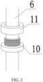
- the optical fiber holder 7includes an annular boss 10 and a nut 11.
- the nut 11is threadedly connected to the annular boss 10.
- the inner diameter of the annular boss 10is slightly less than the outer diameter of the optical fiber probe 6 to facilitate sleeving of an optical fiber.
- the outer diameter of the upper part of the annular boss 10is greater than the caliber of the through hole 13 on the silica gel sheet 12.
- the through hole 13 on the silica gel sheet 12is sleeved on the upper part of the annular boss 10.
- the optical fiber holder 7can perform linear reciprocating motion within the elastic limit of the silica gel sheet 12 along the hole passing direction of the mounting hole.
- the silica gel sheet 12plays a role of fixing the optical fiber holder 7, and allows the optical fiber holder 7 to have a certain movement space, which makes it convenient for the optical fiber probe 6 to be attached to the scalp of a patient more tightly and prevents the optical fiber probe 6 from falling and affecting the testing result without causing damage to the scalp of the patient caused by the excessive compression.
- the eight through holes 13 on the silica gel sheet 12are respectively sleeved on the annular boss 10 of eight optical fiber holders 7, and then the nut 11 is tightened; next, the coil 2 is placed inside the coil housing 1, and the two inner rings of the coil 2 are fastened by the two racetrack oval shaped bosses 3; the silica gel sheet 12 is placed onto the coil 2 to enable the eight through holes 13 on the silica gel sheet 12 to align with the eight mounting holes on the housing; the eight optical fiber probes 6 separately pass through a rear cover of the coil housing 1, are inserted into the optical fiber holders 7, and extracted from the front of the coil housing 1 about 3 cm; and then the rear cover of the coil housing 1 is covered.
- a buffer silica gel head 8is provided on the end of the optical fiber probe 6 in contact with the scalp of the patient, and is used for buffering the damage of the silica gel probe on the scalp of the patient, which improves the comfort of the patient.
- the buffer silica gel head 8is dark, which has the function of protecting from light, and prevents the interference of the external light so as to further improve the testing accuracy.
- the optical fiber holder 7is made of non-metal, which has the purpose of preventing the interference of a magnetic field generated by the TMS coil 2 to affect the therapeutic effect.
- several cable tie holes 9are provided on the side surface of the coil housing 1, which has the function of enabling a cable tie or a ribbon to pass through the cable tie hole 9 to fix the TMS coil and the head of the patient and preventing the TMS coil from not tightly attaching to the head of the patient.
- the front of the coil housing 1is a concave arc surface, and the radius of the concave arc surface is 100 ⁇ 10 mm.
- the front of the coil housing 1is configured as a concave arc surface to better attach the TMS coil to the head of the human body.
- This embodimentprovides an integrated TMS coil for brain function testing and treatment, and differ from embodiment 1 in that in this embodiment, the coil 2 is formed by winding a hollow copper tube.
- the interior of the hollow copper tubeis used for circulating a cooling liquid.
- a water inlet and a water outletare formed at a position where the coil 2 is connected to a TMS instrument 14. The water inlet and the water outlet are respectively in communication with two ports of the hollow copper tube.
- a TMS host, a water pump, a water tank, and a radiatorare provided inside the TMS instrument 14.
- the water pumpis separately in communication with the water tank and the water inlet.
- the radiatoris separately in communication with the water outlet and the water tank.
- the cooling liquidis circulated in the water tank, the hollow copper tube, and the radiator to cool the coil 2.
- the hollow copper tubeserves as a TMS coil and a cooling water tube simultaneously, which saves the space inside the TMS coil and improves the heat-dissipation effect.
- liquid drainage treatmentneeds to be performed first through the water pump, and the TMS coil can be removed after the cooling liquid inside the TMS coil is completed draining.
- the water pump, the radiator, and the TMS host in this embodimentrun synchronously.
- the cooling liquidstarts to be introduced for cooling the coil 2, which can effectively decrease the temperature during the TMS coil operation.
- the radiatorincludes a heat-dissipation tube and a heat-dissipation fan.
- the heat-dissipation fanis used for dissipating the heat inside the heat-dissipation tube into the external air.
Landscapes
- Health & Medical Sciences (AREA)
- Engineering & Computer Science (AREA)
- Life Sciences & Earth Sciences (AREA)
- Biomedical Technology (AREA)
- Physics & Mathematics (AREA)
- Radiology & Medical Imaging (AREA)
- Veterinary Medicine (AREA)
- Animal Behavior & Ethology (AREA)
- Nuclear Medicine, Radiotherapy & Molecular Imaging (AREA)
- Public Health (AREA)
- General Health & Medical Sciences (AREA)
- Microelectronics & Electronic Packaging (AREA)
- Neurology (AREA)
- Molecular Biology (AREA)
- Surgery (AREA)
- Medical Informatics (AREA)
- Heart & Thoracic Surgery (AREA)
- Pathology (AREA)
- Biophysics (AREA)
- Thermal Sciences (AREA)
- Spectroscopy & Molecular Physics (AREA)
- General Physics & Mathematics (AREA)
- Optics & Photonics (AREA)
- Radiation-Therapy Devices (AREA)
- Magnetic Treatment Devices (AREA)
Description
- The present invention relates to the technical field of brain function testing and Transcranial Magnetic Stimulation (TMS) diagnosis and treatment devices, and in particular, to an integrated TMS coil for brain function testing and treatment.
- TMS diagnosis and treatment technology is a new technology for non-invasive cerebral cortex stimulation and modulation that appeared after 1985. It has been widely used in brain science research and clinical diagnosis and treatment. TMS uses a pulsed transient magnetic field to pass through the skull without hindrance and pain, and induces currents in the skull to stimulate the cerebral cortical nerves to produce a series of physiological and biochemical reactions. TMS affects all levels of molecules, synapses, cells, networks, functional areas, system structures, and decision-making behavior in neuroscience. In recent years, it has received increasing attention in the fields of physical medicine and rehabilitation, psychiatry, neuroscience, etc., and has been gradually promoted in clinical and scientific research.
- The principle of TMS modulating nerve function is to use different stimulation modes and stimulation parameters to act on local nerves and networks, bidirectionally regulating the strength of synaptic connections of nerves, that is, modulating the long-term enhancement or long-term inhibition of the nerve function, and bidirectionally regulating the nerve excitability, regulating the local cerebral blood flow and metabolism, and using this to regulate the nerve function and treat neurological dysfunction diseases.
- TMS is often used to stimulate the motor area of the cerebral cortex, which can make the target muscle controlled by the motor nerve contract and shake. The amplitude of the motor evoked potential on the target muscle is often used to test the stimulation effect, determine the stimulation parameters, and artificially interfere with the nerve function according to a predetermined target to modulate the excitability of the motor nerve. Now it has been discovered that stimulating the rest of the brain (such as the dorsolateral frontal lobe, temporal lobe, and parietal lobe) can treat some neuropsychiatric dysfunction diseases such as depression and schizophrenia, but the stimulation effect can be detected by stimulating these parts without target organs. The effect of conventional high-frequency stimulation is affected by a large variety of factors. These uncertain factors require the correct selections of the stimulation modes and parameters. If the stimulation effect cannot be detected in real time, it is impossible to determine the change in the oxygen consumption of the stimulation site, and thus, it is difficult to determine the effect of TMS on the stimulation site and determine the therapeutic effect of TMS, which hinders the application, development, and promotion of TMS.
- The excitement and activity of the brain increase metabolism and oxygen consumption. Therefore, at present, only functional magnetic resonance and positron emission tomography imaging systems are used to detect the changes in cerebral blood flow and biochemical metabolism of the non-motor area of the brain stimulated by TMS to determine the therapeutic effect after TMS stimulation. However, the two devices are very expensive, the testing time is long, the head cannot move during the testing process, the therapeutic effect cannot be detected in real time during the treatment process, and the parameters of TMS magnetic stimulation treatment cannot be adjusted according to the real-time therapeutic effect, which reduces the therapeutic effect.
- Chinese patent having the application No.
CN103007432B discloses an integrated device for brain function modulation and testing on July 1, 2015. A silica gel sleeve is sleeved on the surface of a TMS coil. Several holes at different distances are provided on an inner ring and an outer ring of the silica gel sleeve for facilitating inserting near-infrared transmitting and receiving probes. Due to the elasticity of the silica gel sleeve, the probes can be firmly held and upper and lower positions of the probes can be freely adjusted to ensure that the probes are in close contact with the scalp of the detection site. A miniature near-infrared brain function testing device uses a processor to respectively set the transmitting and receiving frequencies of near-infrared rays having wavelengths of 690 nm and 830 nm. A time division multiplexing mode is used to sequentially light up several LD/LED transmitting light sources in turn distributed at the central part of a stimulation coil. Signals detected by surrounding probes are processed and display the changes in deoxygenated hemoglobin and blood flow on a liquid crystal screen to reflect the changes in the strength, range, and depth of functional activities of the brain regions corresponding to sites of each detection channel during TMS. The coil in the prior art still has a large variety of problems that need to be solved urgently, such as the arrangement scheme of the probe of how to arrange the probes to perfectly integrate a detection region of the probe with a treatment region of the TMS coil to achieve an optimal therapeutic effect and testing effect while ensuring that the optical fiber probe and the structure of the TMS coil do not interfere with each other; how to improve the comfort of patients during treatment and testing; in addition, for the large heat generated during the TMS coil operation, how to arrange a heat-dissipation system to ensure a good heat-dissipation effect without affecting the internal structure of the TMS coil.WO 2010/127044 A1 discloses spectroscopic methods and systems that determine thresholds at which neuronal target tissue sites respond detectably to various stimuli, and that determine and monitor appropriate stimuli parameters and stimulation protocols directed to neuronal target tissue sites. Spectroscopic methods and systems are used to target the administration of stimuli and stimulation protocols to desired neuronal target sites, to detect and monitor responses to stimuli at the desired neuronal target site(s). Stimuli producing undesirable and/or unsafe responses may be detected, and automated alarms or shut-off protocols may be implemented to enhance the safety of stimulation protocols.
Nathan A Parks et AI: "Examining cortical dynamics and connectivity with simultaneous single-pulse transcranial magnetic stimulation and fast optical imaging", Neuroimage, Elsevier, Amsterdam, NL, vol. 59, no. 3, 29 August 2011, discloses a method of imaging TMS-evoked activity using a non-invasive fast optical imaging tool, the event-related optical signal (EROS). EROS measures changes in the scattering of near-infrared light that occur synchronously with electrical activity in cortical tissue. EROS has temporal and spatial resolution allowing the dynamics and spatial spread of a TMS pulse to be measured.CN 107 497 051 A discloses a near-infrared signal-controlled transcranial magnetic stimulation device, comprising a positioning cap, a fNIRS signal acquisition system arranged on the positioning cap, a TMS system and an analysis control device which is connected to the TMS system and the fNIRS signal acquisition system. The near-infrared signal-controlled transcranial magnetic stimulation device utilizes the near infrared signal of the subject to set personalized transcranial magnetic stimulation parameters, avoiding over stimulation or under stimulation.
It is the object of the present invention to provide an improved integrated TMS coil.
This object is solved by the subject matter of the independent claims.
Embodiments are defined in the dependent claims. - The purpose of the present invention is to provide an integrated TMS coil for brain function testing and treatment for the existing problems in the prior art. Optical fiber probes are mounted on the TMS coil, a therapeutic effect is detected in real time by a near-infrared brain function imager, and stimulation parameters of the TMS coil are adjusted according to the therapeutic effect, so as to achieve an optimal therapeutic effect.
- In order to achieve the purpose above, the technical solution of the present invention is:
an integrated TMS coil for brain function testing and treatment, including a coil housing, where a figure-eight coil is provided inside the coil housing, the coil housing is provided with two racetrack oval shaped bosses, and the two racetrack oval shaped bosses are embedded in two inner rings of the coil for limiting a position of the coil; the two racetrack oval shaped bosses are each formed with two mounting holes, and two mounting holes are formed at each of the upper and lower sides of an outer ring of the coil; the mounting holes are each provided with an optical fiber holder for mounting an optical fiber probe; a silica gel sheet is provided inside the coil housing, eight through holes are formed on the silica gel sheet, positions of the eight through holes respectively correspond to those of the eight mounting holes on the coil housing, and the through holes on the silica gel sheet are sleeved inside the optical fiber holders for limiting movement of the optical fiber holders; a lead-out of the coil passes through the bottom of the coil housing and is connected to a TMS instrument; a signal end of the optical fiber probe is connected to a near-infrared brain function imager, a probing end of the optical fiber probe passes through the back and the front of the coil housing, and movement of the optical fiber probe is limited by the optical fiber holder and the silica gel sheet provided inside the coil housing. - Specifically, the positions of the eight mounting holes on the coil housing are defined as: a plane rectangular coordinate system is created by using the central point of the coil as an origin, the horizontal direction as X axis, and the vertical direction as Y axis; the coordinates of the mounting holes on the two racetrack oval shaped bosses from left to right are respectively: (-45, 0), (-15, 0), (15, 0), and (45, 0); the coordinates of the two mounting holes at the upper side of the outer ring of the coil from left to right are respectively: (-15, 30) and (15, 30); the coordinates of the two mounting holes at the lower side of the outer ring of the coil from left to right are respectively: (-15, -30) and (15, -30); the two mounting holes on the racetrack oval shaped boss are arranged close to the edges of the inner rings of the coil, and the four mounting holes at the upper and lower sides of the outer ring of the coil housing are arranged close to the edges of the outer rings of the coil. By using this arrangement approach, a therapeutic region of the coil can overlap with a detection region of the optical fiber probe to the greatest extent so as to ensure the testing and therapeutic effects while making full use of the space inside the TMS coil, and the testing and treatment run independently and synchronously, and do not interfere with each other.
- Specifically, the optical fiber probes include four transmitting optical fiber probes and four receiving optical fiber probes; the eight mounting holes are respectively used for mounting the four transmitting optical fiber probes and the four receiving optical fiber probes; the two mounting holes on the racetrack oval shaped boss are respectively used for mounting one transmitting optical fiber probe and one receiving optical fiber probe; and the two mounting holes at the upper side/lower left of the outer ring of the coil are respectively used for mounting one transmitting optical fiber probe and one receiving optical fiber probe.
- Specifically, the coil is formed by winding a hollow copper tube, and the interior of the hollow copper tube is used for circulating a cooling liquid; a water inlet and a water outlet are formed at a position where the coil is connected to the TMS instrument, and the water inlet and the water outlet are respectively in communication with two ports of the hollow copper tube; a TMS host, a water pump, a water tank, and a radiator are provided inside the TMS instrument; the water pump is separately in communication with the water tank and the water inlet, and the radiator is separately in communication with the water outlet and the water tank; and the cooling liquid is circulated in the water tank, the hollow copper tube, and the radiator to cool the coil. By introducing the cooling liquid into the hollow copper tube, the hollow copper tube serves as a TMS coil and a cooling water tube simultaneously, which saves the space inside the TMS coil and improves the heat-dissipation effect.
- Specifically, the optical fiber holder includes an annular boss and a nut, and the nut is threadedly connected to the annular boss; the inner diameter of the annular boss is slightly less than the outer diameter of the optical fiber probe to facilitate sleeving of an optical fiber; the outer diameter of the upper part of the annular boss is greater than the caliber of the through hole on the silica gel sheet, and the through hole on the silica gel sheet is sleeved on the upper part of the annular boss. The optical fiber holder can perform linear reciprocating motion within the elastic limit of the silica gel sheet along the hole passing direction of the mounting hole. The silica gel sheet plays a role of fixing the optical fiber holder, and allows the optical fiber holder to have a certain movement space, which makes it convenient for the optical fiber probe to be attached to the scalp of a patient more tightly and prevents the optical fiber probe from falling and affecting the testing result without causing damage to the scalp of the patient caused by the excessive compression.
- Specifically, a buffer silica gel head is provided on the end of the optical fiber probe in contact with the scalp of the patient, and is used for buffering the damage of the optical fiber probe on the scalp of the patient, which improves the comfort of the patient.
- Specifically, the optical fiber holder is made of non-metal, which has the purpose of preventing the interference of a magnetic field generated by the TMS coil to affect the therapeutic effect.
- Specifically, several cable tie holes are formed on the side surface of the coil housing, which has the function of enabling a cable tie or a ribbon to pass through the cable tie hole to fix the TMS coil and the head of the patient and preventing the TMS coil from not tightly attaching to the head of the patient.
- Specifically, the front of the coil housing is a concave arc surface, and the radius of the concave arc surface is 100 mm; and the front of the coil housing is configured as a concave arc surface to better attach the TMS coil to the head of the human body.
- Specifically, the coil housing is made of an insulating and thermal insulating material.
- Compared with the prior art, the beneficial effects of the present invention are: (1) in the present invention, mounting holes are formed on the coil housing for mounting the optical fiber probes; the signal end of the optical fiber probe is connected to the near-infrared brain function imager so as to detect the therapeutic effect by the near-infrared brain function imager in real time in the process of performing magnetic stimulation treatment using the TMS coil, and then adjust parameters of the TMS coil according to the therapeutic effect, which greatly improves the therapeutic effect of the TMS coil; (2) in the present invention, the optical fiber probes arranged on the coil housing and the TMS coil do not interfere with each other, and independently and simultaneously work, which makes full use of the internal space of the coil, and greatly decreases the volume of the TMS coil; moreover, all the optical fiber probes are arranged close to the edges of the inner rings/outer rings of the TMS coil, so that the detection region of the optical fiber probe overlaps with the treatment region of the TMS coil to the greatest extent, and the testing and treatment are fed back in real time, and verify mutually, which improves the accuracy of testing and the effectiveness of treatment; (3) in the present invention, the optical fiber probes are embedded inside the through holes on the silica gel sheet through the optical fiber holders, so that the optical fiber probes can perform linear reciprocating motion only within the elastic limit range of the silica gel sheet along the hole passing direction of the mounting holes on the coil housing, which makes it convenient for the optical fiber probe to be attached to the scalp of the patient more tightly and prevents the optical fiber probe from falling and affecting the testing result without causing damage to the scalp of the patient caused by the excessive compression; (4) in the present invention, the cooling liquid is introduced into the coil (the hollow copper tube) for cooling the TMS coil; the hollow copper tube serves as a TMS coil and a cooling water tube simultaneously, which saves the space inside the TMS coil and improves the heat-dissipation effect.
FIG. 1 is a schematic structural diagram of an entire integrated TMS coil for brain function testing and treatment of the present invention.FIG. 2 is a schematic structural diagram of optical fiber holders of the present invention.FIG. 3 is a schematic structural diagram of arrangements of mounting holes and a coil on a coil housing of the present invention.FIG. 4 is a schematic distribution diagram of through holes on a silica gel sheet of the present invention.FIG. 5 is a schematic diagram where a TMS coil is connected to a TMS instrument and a near-infrared brain function imager in embodiments of the present invention.- Reference numerals: 1. coil housing; 2. coil; 3. racetrack oval shaped boss; 4. first mounting hole; 5. second mounting hole; 6. optical fiber probe; 7. optical fiber holder; 8. buffer silica gel head; 9. cable tie hole; 10. annular boss; 11. nut; 12. silica gel sheet; 13. through hole; 14. TMS instrument; 15. near-infrared brain function imager.
- The technical solutions and exemplary embodiments of the present invention are clearly and fully described below with reference to the accompanying drawings. The scope of the invention is defined by the claims.
- As shown in
FIGS. 1 ,4 , and5 , this embodiment provides an integrated TMS coil for brain function testing and treatment, including acoil housing 1. A figure-eightcoil 2 is provided inside thecoil housing 1. Thecoil housing 1 is provided with two racetrack oval shapedbosses 3. The two racetrack oval shapedbosses 3 are embedded in two inner rings of thecoil 2 for limiting a position of the coil, and are respectively provided with two mounting holes. Two mounting holes are respectively at upper and lower sides of an outer ring of thecoil 2. The mounting holes are each provided withoptical fiber holders 7 for mounting optical fiber probes 6. Asilica gel sheet 12 is provided inside thecoil housing 1, and is provided with eight throughholes 13. Positions of the eight throughholes 13 respectively correspond to those of eight mounting holes on thecoil housing 1. The through holes 13 on thesilica gel sheet 12 are sleeved inside theoptical fiber holders 7 for limiting movement of the optical fiber holders, a lead-out of thecoil 2 passes through the bottom of thecoil housing 1 and is connected to aTMS instrument 14. A signal end of theoptical fiber probe 6 is connected to a near-infraredbrain function imager 15. A probing end of theoptical fiber probe 6 passes through the back and the front of thecoil housing 1. The movement of theoptical fiber probe 6 is limited by theoptical fiber holder 7 and thesilica gel sheet 12 provided inside thecoil housing 1. Both the testing principle of the near-infraredbrain function imager 15 and the working principle of a TMS diagnosis and treatment device are prior arts, and will not be illustrated here. - Specifically, as shown in
FIG. 3 , the positions of the eight mounting holes on thecoil housing 1 are defined as: a plane rectangular coordinate system is created by using the central point of thecoil 2 as an origin, the horizontal direction as X axis, and the vertical direction as Y axis. The coordinates of the mounting holes on the two racetrack oval shapedbosses 3 from left to right are respectively: (-45, 0), (-15, 0), (15, 0), and (45, 0). The coordinates of the two mounting holes at the upper side of the outer ring of thecoil 2 from left to right are respectively: (-15, 30) and (15, 30). The coordinates of the two mounting holes at the lower side of the outer ring of thecoil 2 from left to right are respectively: (-15, -30) and (15, -30). The two mounting holes on the racetrack oval shapedboss 3 are arranged close to the edges of the inner rings of thecoil 2. The four mounting holes at the upper and lower sides of the outer ring of thecoil housing 1 are arranged close to the edges of the outer rings of thecoil 2. The coordinates of edge extreme points of thecoil 2 in left, right, up, and down directions are respectively: (-65, 0), (65, 0), (-30, 32.5)/(30, 32.5) and (-30, -32.5)/(30, -32.5). By using this arrangement approach, a treatment region of thecoil 2 can overlap with a detection region of theoptical fiber probe 6 to the greatest extent so as to ensure the testing and therapeutic effects while making full use of the space inside the TMS coil, and the testing and treatment run independently and synchronously, and do not interfere with each other. - Specifically, the
optical fiber probe 6 includes four transmitting optical fiber probes and four receiving optical fiber probes. The eight mounting holes include four first mountingholes 4 and four second mounting holes 5. The first mountingholes 4 are used for mounting the transmitting optical fiber probes. The second mounting holes 5 are used for mounting the receiving optical fiber probes. The mounting hole on the left of the racetrack oval shapedboss 3 is the first mountinghole 4, which is used for mounting the transmitting optical fiber probe. The mounting hole on the right of the racetrack oval shapedboss 3 is thesecond mounting hole 5, which is used for mounting the receiving optical fiber probe. The mounting holes on the left of the upper side/lower side of the outer ring of thecoil 2 are first mountingholes 4, which are used for mounting the transmitting optical fiber probes. The mounting holes on the right of the upper side/lower side of the outer ring of thecoil 2 are second mountingholes 5, which are used for mounting the receiving optical fiber probes. - Specifically, as shown in
FIG. 2 , theoptical fiber holder 7 includes anannular boss 10 and anut 11. Thenut 11 is threadedly connected to theannular boss 10. The inner diameter of theannular boss 10 is slightly less than the outer diameter of theoptical fiber probe 6 to facilitate sleeving of an optical fiber. The outer diameter of the upper part of theannular boss 10 is greater than the caliber of the throughhole 13 on thesilica gel sheet 12. The throughhole 13 on thesilica gel sheet 12 is sleeved on the upper part of theannular boss 10. Theoptical fiber holder 7 can perform linear reciprocating motion within the elastic limit of thesilica gel sheet 12 along the hole passing direction of the mounting hole. Thesilica gel sheet 12 plays a role of fixing theoptical fiber holder 7, and allows theoptical fiber holder 7 to have a certain movement space, which makes it convenient for theoptical fiber probe 6 to be attached to the scalp of a patient more tightly and prevents theoptical fiber probe 6 from falling and affecting the testing result without causing damage to the scalp of the patient caused by the excessive compression. - Further, when the TMS coil in this embodiment is assembled, first, the eight through
holes 13 on thesilica gel sheet 12 are respectively sleeved on theannular boss 10 of eightoptical fiber holders 7, and then thenut 11 is tightened; next, thecoil 2 is placed inside thecoil housing 1, and the two inner rings of thecoil 2 are fastened by the two racetrack oval shapedbosses 3; thesilica gel sheet 12 is placed onto thecoil 2 to enable the eight throughholes 13 on thesilica gel sheet 12 to align with the eight mounting holes on the housing; the eightoptical fiber probes 6 separately pass through a rear cover of thecoil housing 1, are inserted into theoptical fiber holders 7, and extracted from the front of thecoil housing 1 about 3 cm; and then the rear cover of thecoil housing 1 is covered. - Specifically, a buffer
silica gel head 8 is provided on the end of theoptical fiber probe 6 in contact with the scalp of the patient, and is used for buffering the damage of the silica gel probe on the scalp of the patient, which improves the comfort of the patient. The buffersilica gel head 8 is dark, which has the function of protecting from light, and prevents the interference of the external light so as to further improve the testing accuracy. - Specifically, the
optical fiber holder 7 is made of non-metal, which has the purpose of preventing the interference of a magnetic field generated by theTMS coil 2 to affect the therapeutic effect. - Specifically, several cable tie holes 9 are provided on the side surface of the
coil housing 1, which has the function of enabling a cable tie or a ribbon to pass through thecable tie hole 9 to fix the TMS coil and the head of the patient and preventing the TMS coil from not tightly attaching to the head of the patient. - Specifically, the front of the
coil housing 1 is a concave arc surface, and the radius of the concave arc surface is 100±10 mm. The front of thecoil housing 1 is configured as a concave arc surface to better attach the TMS coil to the head of the human body. - This embodiment provides an integrated TMS coil for brain function testing and treatment, and differ from
embodiment 1 in that in this embodiment, thecoil 2 is formed by winding a hollow copper tube. The interior of the hollow copper tube is used for circulating a cooling liquid. A water inlet and a water outlet are formed at a position where thecoil 2 is connected to aTMS instrument 14. The water inlet and the water outlet are respectively in communication with two ports of the hollow copper tube. A TMS host, a water pump, a water tank, and a radiator are provided inside theTMS instrument 14. The water pump is separately in communication with the water tank and the water inlet. The radiator is separately in communication with the water outlet and the water tank. The cooling liquid is circulated in the water tank, the hollow copper tube, and the radiator to cool thecoil 2. By introducing the cooling liquid into the hollow copper tube, the hollow copper tube serves as a TMS coil and a cooling water tube simultaneously, which saves the space inside the TMS coil and improves the heat-dissipation effect. - When the TMS coil needs to be disassembled from the
TMS instrument 14, liquid drainage treatment needs to be performed first through the water pump, and the TMS coil can be removed after the cooling liquid inside the TMS coil is completed draining. The water pump, the radiator, and the TMS host in this embodiment run synchronously. When the TMS coil is powered on, the cooling liquid starts to be introduced for cooling thecoil 2, which can effectively decrease the temperature during the TMS coil operation. - Further, the radiator includes a heat-dissipation tube and a heat-dissipation fan. The heat-dissipation fan is used for dissipating the heat inside the heat-dissipation tube into the external air.
- Although the embodiments of the present invention are illustrated and described, it can be understood that persons of ordinary skill in the art can make various changes, modifications, substitutions and variations on these embodiments without departing the principle of the present invention. The scopes of the present invention are defined by the appended claims.
Claims (10)
- An integrated Transcranial Magnetic Stimulation (TMS) coil for brain function testing and treatment, comprising a coil housing (1) and optical fiber probes (6) configured for connecting, with a signal end of the optical fiber probes, to a near-infrared brain function imager (15), wherein a figure-eight coil (2) is provided inside the coil housing (1), the coil housing (1) is provided with two racetrack oval shaped bosses (3), and the two racetrack oval shaped bosses (3) are embedded in two inner rings of the coil (2) for limiting a position of the coil (2); the two racetrack oval shaped bosses (3) are each formed with two mounting holes (4, 5), and two mounting holes (4, 5) are formed at each of the upper and lower sides of an outer ring of the coil (2); the mounting holes (4, 5) are each provided with an optical fiber holder (7) for mounting an optical fiber probe (6); a silica gel sheet (12) is provided inside the coil housing (1), eight through holes (13) are formed on the silica gel sheet (12), positions of the eight through holes (13) respectively correspond to those of the eight mounting holes (4, 5) on the coil housing (1), and the through holes (13) on the silica gel sheet (12) are sleeved inside the optical fiber holders (7) for limiting movement of the optical fiber holders (7); a lead-out of the coil (2) passes through the bottom of the coil housing (1) and is configured for connecting to a TMS instrument (14), wherein a probing end of the optical fiber probes (6) passes through the back and the front of the coil housing (1), and movement of the optical fiber probes (6) is limited by the optical fiber holders (7) and the silica gel sheet (12) provided inside the coil housing (1).
- The integrated TMS coil for brain function testing and treatment according to claim 1, wherein the positions of the eight mounting holes (4, 5) on the coil housing (1) are defined as: a plane rectangular coordinate system is created by using the central point of the coil (2) as an origin, the horizontal direction as X axis, and the vertical direction as Y axis; the coordinates of the mounting holes (4, 5) on the two racetrack oval shaped bosses (3) from left to right are respectively: (-45, 0), (-15, 0), (15, 0), and (45, 0); the coordinates of the two mounting holes (4, 5) at the upper side of the outer ring of the coil (2) from left to right are respectively: (-15, 30) and (15, 30); and the coordinates of the two mounting holes (4, 5) at the lower side of the outer ring of the coil (2) from left to right are respectively: (-15, - 30) and (15, -30).
- The integrated TMS coil for brain function testing and treatment according to claim 2, wherein the optical fiber probes (6) comprise four transmitting optical fiber probes (6) and four receiving optical fiber probes (6); the eight mounting holes (4, 5) are respectively used for mounting the four transmitting optical fiber probes (6) and the four receiving optical fiber probes (6); the two mounting holes (4, 5) on the racetrack oval shaped boss (3) are respectively used for mounting one transmitting optical fiber probe (6) and one receiving optical fiber probe (6); and the two mounting holes (4, 5) at the upper side/lower left of the outer ring of the coil (2) are respectively used for mounting one transmitting optical fiber probe (6) and one receiving optical fiber probe (6).
- The integrated TMS coil for brain function testing and treatment according to claim 1, wherein the coil (2) is formed by winding a hollow copper tube, and the interior of the hollow copper tube is used for circulating a cooling liquid; a water inlet and a water outlet are formed at a position where the coil (2) is connected to the TMS instrument (14), and the water inlet and the water outlet are respectively in communication with two ports of the hollow copper tube; a TMS host, a water pump, a water tank, and a radiator are provided inside the TMS instrument (14); the water pump is separately in communication with the water tank and the water inlet, and the radiator is separately in communication with the water outlet and the water tank; and the cooling liquid is circulated in the water tank, the hollow copper tube, and the radiator to cool the coil (2).
- The integrated TMS coil for brain function testing and treatment according to claim 1, wherein the optical fiber holder (7) comprises an annular boss (10) and a nut (11), and the nut (11) is threadedly connected to the annular boss (10); the inner diameter of the annular boss (10) is slightly less than the outer diameter of the optical fiber probe (6) to facilitate sleeving of an optical fiber; and the outer diameter of the upper part of the annular boss (10) is greater than the caliber of the through hole (13) on the silica gel sheet (12), and the through hole (13) on the silica gel sheet (12) is sleeved on the upper part of the annular boss (10).
- The integrated TMS coil for brain function testing and treatment according to claim 1, wherein a buffer silica gel head (8) is provided on the end of the optical fiber probe (6) in contact with the scalp of a patient.
- The integrated TMS coil for brain function testing and treatment according to claim 1, wherein the optical fiber holder (7) is made of plastic.
- The integrated TMS coil for brain function testing and treatment according to claim 1, wherein several cable tie holes (9) are formed on the side surface of the coil housing (1).
- The integrated TMS coil for brain function testing and treatment according to claim 1, wherein the front of the coil housing (1) is a concave arc surface (100), and the radius of the concave arc surface is 100 mm.
- The integrated TMS coil for brain function testing and treatment according to claim 1, wherein the coil housing (1) is made of an insulating and thermal insulating material.
Applications Claiming Priority (1)
| Application Number | Priority Date | Filing Date | Title |
|---|---|---|---|
| PCT/CN2019/086108WO2020223942A1 (en) | 2019-05-09 | 2019-05-09 | Integrated tms coil paddle for brain function measurement and treatment |
Publications (3)
| Publication Number | Publication Date |
|---|---|
| EP3906840A1 EP3906840A1 (en) | 2021-11-10 |
| EP3906840A4 EP3906840A4 (en) | 2022-01-19 |
| EP3906840B1true EP3906840B1 (en) | 2024-09-04 |
Family
ID=68289726
Family Applications (1)
| Application Number | Title | Priority Date | Filing Date |
|---|---|---|---|
| EP19928235.1AActiveEP3906840B1 (en) | 2019-05-09 | 2019-05-09 | Integrated tms coil paddle for brain function measurement and treatment |
Country Status (4)
| Country | Link |
|---|---|
| US (1) | US12097381B2 (en) |
| EP (1) | EP3906840B1 (en) |
| CN (1) | CN110392594B (en) |
| WO (1) | WO2020223942A1 (en) |
Families Citing this family (14)
| Publication number | Priority date | Publication date | Assignee | Title |
|---|---|---|---|---|
| US20180001107A1 (en) | 2016-07-01 | 2018-01-04 | Btl Holdings Limited | Aesthetic method of biological structure treatment by magnetic field |
| US11247039B2 (en) | 2016-05-03 | 2022-02-15 | Btl Healthcare Technologies A.S. | Device including RF source of energy and vacuum system |
| US11534619B2 (en) | 2016-05-10 | 2022-12-27 | Btl Medical Solutions A.S. | Aesthetic method of biological structure treatment by magnetic field |
| US10583287B2 (en) | 2016-05-23 | 2020-03-10 | Btl Medical Technologies S.R.O. | Systems and methods for tissue treatment |
| US10556122B1 (en) | 2016-07-01 | 2020-02-11 | Btl Medical Technologies S.R.O. | Aesthetic method of biological structure treatment by magnetic field |
| US11141219B1 (en) | 2016-08-16 | 2021-10-12 | BTL Healthcare Technologies, a.s. | Self-operating belt |
| US12156689B2 (en) | 2019-04-11 | 2024-12-03 | Btl Medical Solutions A.S. | Methods and devices for aesthetic treatment of biological structures by radiofrequency and magnetic energy |
| ES2926904T3 (en) | 2019-04-11 | 2022-10-31 | Btl Medical Solutions A S | Device for the aesthetic treatment of biological structures using radiofrequency and magnetic energy |
| CN110947100B (en)* | 2019-12-20 | 2023-03-31 | 武汉资联虹康科技股份有限公司 | Method for positioning and correcting magnetic stimulation beat optical fiber |
| WO2021224678A1 (en) | 2020-05-04 | 2021-11-11 | Btl Medical Technologies S.R.O. | Device and method for unattended treatment of a patient |
| US11878167B2 (en) | 2020-05-04 | 2024-01-23 | Btl Healthcare Technologies A.S. | Device and method for unattended treatment of a patient |
| CN112274779B (en)* | 2020-10-28 | 2022-02-22 | 国家康复辅具研究中心 | Functional near-infrared guidance-based transcranial magnetic stimulation system and method |
| EP4415812A1 (en) | 2021-10-13 | 2024-08-21 | BTL Medical Solutions a.s. | Devices for aesthetic treatment of biological structures by radiofrequency and magnetic energy |
| US11896816B2 (en) | 2021-11-03 | 2024-02-13 | Btl Healthcare Technologies A.S. | Device and method for unattended treatment of a patient |
Family Cites Families (17)
| Publication number | Priority date | Publication date | Assignee | Title |
|---|---|---|---|---|
| JP3839202B2 (en)* | 1999-10-28 | 2006-11-01 | 株式会社日立製作所 | Biological light measuring device and program for causing this device to function |
| US7974671B2 (en)* | 2003-09-19 | 2011-07-05 | Hitachi Medical Corporation | Living body information signal processing system combining living body optical measurement apparatus and brain wave measurement apparatus and probe device used for the same |
| JP4625809B2 (en)* | 2004-07-20 | 2011-02-02 | 俊徳 加藤 | Biological function diagnostic apparatus, biological function diagnostic method, biological probe, biological probe mounting tool, biological probe support tool, and biological probe mounting support tool |
| US7976451B2 (en)* | 2005-06-16 | 2011-07-12 | The United States Of America As Represented By The Department Of Health And Human Services | Transcranial magnetic stimulation system and methods |
| US7998053B2 (en)* | 2006-08-30 | 2011-08-16 | Nexstim Oy | Transcranial magnetic stimulation induction coil device and method of manufacture |
| WO2010127044A1 (en)* | 2009-04-29 | 2010-11-04 | Biophysica Llc | Methods and systems for targeting, dosing and conducting neuronal stimulation protocols and detecting responses |
| JP5896109B2 (en)* | 2010-11-25 | 2016-03-30 | 国立大学法人大阪大学 | Magnetic coil unit for treatment |
| US9682249B2 (en)* | 2011-10-24 | 2017-06-20 | Teijin Pharma Limited | Transcranial magnetic stimulation system |
| RU145012U1 (en)* | 2012-11-23 | 2014-09-10 | Некстим Ой | HEAD TRACKING DEVICE |
| CN103007432B (en)* | 2012-12-21 | 2015-07-01 | 武汉碧萝金科技有限责任公司 | Integrated device for modulating and detecting brain functions |
| US9456784B2 (en)* | 2013-03-14 | 2016-10-04 | The Methodist Hospital | Method and apparatus for providing transcranial magnetic stimulation (TMS) to a patient |
| CN105597234B (en)* | 2015-07-09 | 2018-03-30 | 北京大学 | Multilayer bias figure-eight coil for deep position transcranial magnetic stimulation |
| CN105344012A (en)* | 2015-11-30 | 2016-02-24 | 燕山大学 | Transcranial magnetic stimulation and laser doppler velocity measurement integrated apparatus |
| US10639494B2 (en)* | 2016-09-20 | 2020-05-05 | Rhode Island Board Of Education | Time-varying magnetic field therapy using multistable latching mechanisms |
| CN206228772U (en)* | 2017-04-10 | 2017-06-09 | 甘景梨 | A kind of transcranial magnetic stimulation new coil device |
| CN208611598U (en)* | 2017-07-24 | 2019-03-19 | 深圳英智科技有限公司 | A kind of coil block and magnetic stimulator |
| CN107497051B (en)* | 2017-09-25 | 2024-07-12 | 深圳市浩天脑智科技有限公司 | Transcranial magnetic stimulation device controlled by near infrared signals |
- 2019
- 2019-05-09EPEP19928235.1Apatent/EP3906840B1/enactiveActive
- 2019-05-09USUS17/284,156patent/US12097381B2/enactiveActive
- 2019-05-09CNCN201980001075.2Apatent/CN110392594B/enactiveActive
- 2019-05-09WOPCT/CN2019/086108patent/WO2020223942A1/ennot_activeCeased
Also Published As
| Publication number | Publication date |
|---|---|
| CN110392594B (en) | 2023-05-02 |
| US20210330987A1 (en) | 2021-10-28 |
| US12097381B2 (en) | 2024-09-24 |
| EP3906840A4 (en) | 2022-01-19 |
| CN110392594A (en) | 2019-10-29 |
| EP3906840A1 (en) | 2021-11-10 |
| WO2020223942A1 (en) | 2020-11-12 |
Similar Documents
| Publication | Publication Date | Title |
|---|---|---|
| EP3906840B1 (en) | Integrated tms coil paddle for brain function measurement and treatment | |
| US11207540B2 (en) | Electromagnetic coil assembly | |
| Enatsu et al. | Connections of the limbic network: a corticocortical evoked potentials study | |
| Lobel et al. | Functional MRI of galvanic vestibular stimulation | |
| US20150174418A1 (en) | Device and Methods for Noninvasive Neuromodulation Using Targeted Transcranial Electrical Stimulation | |
| US20090099623A1 (en) | Systems and methods for treatment of medical conditions related to the central nervous system and for enhancing cognitive functions | |
| AU2013266017B2 (en) | Optimising current direction and intensity of transcranial magnetic stimulation | |
| US20200054414A1 (en) | Adjustable headpiece with anatomical markers and methods of use thereof | |
| CN109453453B (en) | A transcranial magnetic stimulation intelligent sleep aid system | |
| WO2009044271A2 (en) | Systems and methods for treatment of medical conditions related to the central nervous system and for enhancing cognitive functions | |
| JP2014502900A (en) | Device for noninvasive deep brain stimulation | |
| Parthoens et al. | Performance characterization of an actively cooled repetitive transcranial magnetic stimulation coil for the rat | |
| US20160030762A1 (en) | Device and method for transcranial magnetic stimulation coil positioning with data integration | |
| CN106137135A (en) | It is applied to the headgear of the electrical combined collection brain signal of transcranial magnetic stimulation | |
| CN114146315B (en) | A transcranial magnetic stimulation system and method | |
| KR101470588B1 (en) | Apparatus and method for brain-brain interfacing | |
| KR20210126835A (en) | Apparatus for improving brain disease and for controlling the same | |
| US20230149744A1 (en) | Therapeutic inhibition and stimulation with transcranial ultrasound | |
| Pérez-Cervera et al. | Mapping functional connectivity in the rodent brain using electric-stimulation fMRI | |
| CN222400001U (en) | An integrated device for transcranial magnetic stimulation and near-infrared brain functional imaging detection | |
| Gindrat et al. | Whole-scalp EEG mapping of somatosensory evoked potentials in macaque monkeys | |
| CN113546325B (en) | Transcranial magnetic stimulation intervention device | |
| CN114601430A (en) | Cortex function connection positioning device based on near-infrared light stimulation | |
| CN220110088U (en) | Near infrared brain function imaging acupuncture head cap | |
| Zhao et al. | Identification of the human cerebral cortical hemodynamic response to passive whole-body movements using near-infrared spectroscopy |
Legal Events
| Date | Code | Title | Description |
|---|---|---|---|
| STAA | Information on the status of an ep patent application or granted ep patent | Free format text:STATUS: THE INTERNATIONAL PUBLICATION HAS BEEN MADE | |
| PUAI | Public reference made under article 153(3) epc to a published international application that has entered the european phase | Free format text:ORIGINAL CODE: 0009012 | |
| STAA | Information on the status of an ep patent application or granted ep patent | Free format text:STATUS: REQUEST FOR EXAMINATION WAS MADE | |
| 17P | Request for examination filed | Effective date:20210802 | |
| AK | Designated contracting states | Kind code of ref document:A1 Designated state(s):AL AT BE BG CH CY CZ DE DK EE ES FI FR GB GR HR HU IE IS IT LI LT LU LV MC MK MT NL NO PL PT RO RS SE SI SK SM TR | |
| A4 | Supplementary search report drawn up and despatched | Effective date:20211217 | |
| RIC1 | Information provided on ipc code assigned before grant | Ipc:A61N 2/02 20060101ALI20211213BHEP Ipc:A61B 5/00 20060101AFI20211213BHEP | |
| DAV | Request for validation of the european patent (deleted) | ||
| DAX | Request for extension of the european patent (deleted) | ||
| GRAP | Despatch of communication of intention to grant a patent | Free format text:ORIGINAL CODE: EPIDOSNIGR1 | |
| STAA | Information on the status of an ep patent application or granted ep patent | Free format text:STATUS: GRANT OF PATENT IS INTENDED | |
| INTG | Intention to grant announced | Effective date:20240515 | |
| GRAS | Grant fee paid | Free format text:ORIGINAL CODE: EPIDOSNIGR3 | |
| GRAA | (expected) grant | Free format text:ORIGINAL CODE: 0009210 | |
| STAA | Information on the status of an ep patent application or granted ep patent | Free format text:STATUS: THE PATENT HAS BEEN GRANTED | |
| AK | Designated contracting states | Kind code of ref document:B1 Designated state(s):AL AT BE BG CH CY CZ DE DK EE ES FI FR GB GR HR HU IE IS IT LI LT LU LV MC MK MT NL NO PL PT RO RS SE SI SK SM TR | |
| P01 | Opt-out of the competence of the unified patent court (upc) registered | Free format text:CASE NUMBER: APP_44629/2024 Effective date:20240731 | |
| REG | Reference to a national code | Ref country code:GB Ref legal event code:FG4D | |
| REG | Reference to a national code | Ref country code:CH Ref legal event code:EP | |
| REG | Reference to a national code | Ref country code:IE Ref legal event code:FG4D | |
| REG | Reference to a national code | Ref country code:DE Ref legal event code:R096 Ref document number:602019058541 Country of ref document:DE | |
| REG | Reference to a national code | Ref country code:LT Ref legal event code:MG9D | |
| REG | Reference to a national code | Ref country code:NL Ref legal event code:MP Effective date:20240904 | |
| PG25 | Lapsed in a contracting state [announced via postgrant information from national office to epo] | Ref country code:NO Free format text:LAPSE BECAUSE OF FAILURE TO SUBMIT A TRANSLATION OF THE DESCRIPTION OR TO PAY THE FEE WITHIN THE PRESCRIBED TIME-LIMIT Effective date:20241204 | |
| PG25 | Lapsed in a contracting state [announced via postgrant information from national office to epo] | Ref country code:GR Free format text:LAPSE BECAUSE OF FAILURE TO SUBMIT A TRANSLATION OF THE DESCRIPTION OR TO PAY THE FEE WITHIN THE PRESCRIBED TIME-LIMIT Effective date:20241205 Ref country code:PL Free format text:LAPSE BECAUSE OF FAILURE TO SUBMIT A TRANSLATION OF THE DESCRIPTION OR TO PAY THE FEE WITHIN THE PRESCRIBED TIME-LIMIT Effective date:20240904 Ref country code:FI Free format text:LAPSE BECAUSE OF FAILURE TO SUBMIT A TRANSLATION OF THE DESCRIPTION OR TO PAY THE FEE WITHIN THE PRESCRIBED TIME-LIMIT Effective date:20240904 | |
| PG25 | Lapsed in a contracting state [announced via postgrant information from national office to epo] | Ref country code:BG Free format text:LAPSE BECAUSE OF FAILURE TO SUBMIT A TRANSLATION OF THE DESCRIPTION OR TO PAY THE FEE WITHIN THE PRESCRIBED TIME-LIMIT Effective date:20240904 | |
| PG25 | Lapsed in a contracting state [announced via postgrant information from national office to epo] | Ref country code:LV Free format text:LAPSE BECAUSE OF FAILURE TO SUBMIT A TRANSLATION OF THE DESCRIPTION OR TO PAY THE FEE WITHIN THE PRESCRIBED TIME-LIMIT Effective date:20240904 | |
| PG25 | Lapsed in a contracting state [announced via postgrant information from national office to epo] | Ref country code:HR Free format text:LAPSE BECAUSE OF FAILURE TO SUBMIT A TRANSLATION OF THE DESCRIPTION OR TO PAY THE FEE WITHIN THE PRESCRIBED TIME-LIMIT Effective date:20240904 | |
| PG25 | Lapsed in a contracting state [announced via postgrant information from national office to epo] | Ref country code:ES Free format text:LAPSE BECAUSE OF FAILURE TO SUBMIT A TRANSLATION OF THE DESCRIPTION OR TO PAY THE FEE WITHIN THE PRESCRIBED TIME-LIMIT Effective date:20240904 Ref country code:RS Free format text:LAPSE BECAUSE OF FAILURE TO SUBMIT A TRANSLATION OF THE DESCRIPTION OR TO PAY THE FEE WITHIN THE PRESCRIBED TIME-LIMIT Effective date:20241204 | |
| PG25 | Lapsed in a contracting state [announced via postgrant information from national office to epo] | Ref country code:RS Free format text:LAPSE BECAUSE OF FAILURE TO SUBMIT A TRANSLATION OF THE DESCRIPTION OR TO PAY THE FEE WITHIN THE PRESCRIBED TIME-LIMIT Effective date:20241204 Ref country code:PL Free format text:LAPSE BECAUSE OF FAILURE TO SUBMIT A TRANSLATION OF THE DESCRIPTION OR TO PAY THE FEE WITHIN THE PRESCRIBED TIME-LIMIT Effective date:20240904 Ref country code:NO Free format text:LAPSE BECAUSE OF FAILURE TO SUBMIT A TRANSLATION OF THE DESCRIPTION OR TO PAY THE FEE WITHIN THE PRESCRIBED TIME-LIMIT Effective date:20241204 Ref country code:LV Free format text:LAPSE BECAUSE OF FAILURE TO SUBMIT A TRANSLATION OF THE DESCRIPTION OR TO PAY THE FEE WITHIN THE PRESCRIBED TIME-LIMIT Effective date:20240904 Ref country code:HR Free format text:LAPSE BECAUSE OF FAILURE TO SUBMIT A TRANSLATION OF THE DESCRIPTION OR TO PAY THE FEE WITHIN THE PRESCRIBED TIME-LIMIT Effective date:20240904 Ref country code:GR Free format text:LAPSE BECAUSE OF FAILURE TO SUBMIT A TRANSLATION OF THE DESCRIPTION OR TO PAY THE FEE WITHIN THE PRESCRIBED TIME-LIMIT Effective date:20241205 Ref country code:FI Free format text:LAPSE BECAUSE OF FAILURE TO SUBMIT A TRANSLATION OF THE DESCRIPTION OR TO PAY THE FEE WITHIN THE PRESCRIBED TIME-LIMIT Effective date:20240904 Ref country code:ES Free format text:LAPSE BECAUSE OF FAILURE TO SUBMIT A TRANSLATION OF THE DESCRIPTION OR TO PAY THE FEE WITHIN THE PRESCRIBED TIME-LIMIT Effective date:20240904 Ref country code:BG Free format text:LAPSE BECAUSE OF FAILURE TO SUBMIT A TRANSLATION OF THE DESCRIPTION OR TO PAY THE FEE WITHIN THE PRESCRIBED TIME-LIMIT Effective date:20240904 | |
| REG | Reference to a national code | Ref country code:AT Ref legal event code:MK05 Ref document number:1719505 Country of ref document:AT Kind code of ref document:T Effective date:20240904 | |
| PG25 | Lapsed in a contracting state [announced via postgrant information from national office to epo] | Ref country code:NL Free format text:LAPSE BECAUSE OF FAILURE TO SUBMIT A TRANSLATION OF THE DESCRIPTION OR TO PAY THE FEE WITHIN THE PRESCRIBED TIME-LIMIT Effective date:20240904 | |
| PG25 | Lapsed in a contracting state [announced via postgrant information from national office to epo] | Ref country code:PT Free format text:LAPSE BECAUSE OF FAILURE TO SUBMIT A TRANSLATION OF THE DESCRIPTION OR TO PAY THE FEE WITHIN THE PRESCRIBED TIME-LIMIT Effective date:20250106 Ref country code:IS Free format text:LAPSE BECAUSE OF FAILURE TO SUBMIT A TRANSLATION OF THE DESCRIPTION OR TO PAY THE FEE WITHIN THE PRESCRIBED TIME-LIMIT Effective date:20250104 | |
| PG25 | Lapsed in a contracting state [announced via postgrant information from national office to epo] | Ref country code:SM Free format text:LAPSE BECAUSE OF FAILURE TO SUBMIT A TRANSLATION OF THE DESCRIPTION OR TO PAY THE FEE WITHIN THE PRESCRIBED TIME-LIMIT Effective date:20240904 Ref country code:RO Free format text:LAPSE BECAUSE OF FAILURE TO SUBMIT A TRANSLATION OF THE DESCRIPTION OR TO PAY THE FEE WITHIN THE PRESCRIBED TIME-LIMIT Effective date:20240904 | |
| PG25 | Lapsed in a contracting state [announced via postgrant information from national office to epo] | Ref country code:AT Free format text:LAPSE BECAUSE OF FAILURE TO SUBMIT A TRANSLATION OF THE DESCRIPTION OR TO PAY THE FEE WITHIN THE PRESCRIBED TIME-LIMIT Effective date:20240904 Ref country code:EE Free format text:LAPSE BECAUSE OF FAILURE TO SUBMIT A TRANSLATION OF THE DESCRIPTION OR TO PAY THE FEE WITHIN THE PRESCRIBED TIME-LIMIT Effective date:20240904 | |
| PG25 | Lapsed in a contracting state [announced via postgrant information from national office to epo] | Ref country code:CZ Free format text:LAPSE BECAUSE OF FAILURE TO SUBMIT A TRANSLATION OF THE DESCRIPTION OR TO PAY THE FEE WITHIN THE PRESCRIBED TIME-LIMIT Effective date:20240904 | |
| REG | Reference to a national code | Ref country code:DE Ref legal event code:R082 Ref document number:602019058541 Country of ref document:DE Representative=s name:BIOPATENTS IP CONSULTANCY, NL Ref country code:DE Ref legal event code:R081 Ref document number:602019058541 Country of ref document:DE Owner name:WUHAN YIRUIDE MEDICAL EQUIPMENT NEW TECHNOLOGY, CN Free format text:FORMER OWNER: WUHAN ZNION TECHNOLOGY CO., LTD, WUHAN, HUBEI, CN | |
| PG25 | Lapsed in a contracting state [announced via postgrant information from national office to epo] | Ref country code:IT Free format text:LAPSE BECAUSE OF FAILURE TO SUBMIT A TRANSLATION OF THE DESCRIPTION OR TO PAY THE FEE WITHIN THE PRESCRIBED TIME-LIMIT Effective date:20240904 Ref country code:SK Free format text:LAPSE BECAUSE OF FAILURE TO SUBMIT A TRANSLATION OF THE DESCRIPTION OR TO PAY THE FEE WITHIN THE PRESCRIBED TIME-LIMIT Effective date:20240904 | |
| REG | Reference to a national code | Ref country code:DE Ref legal event code:R097 Ref document number:602019058541 Country of ref document:DE | |
| REG | Reference to a national code | Ref country code:GB Ref legal event code:732E Free format text:REGISTERED BETWEEN 20250515 AND 20250521 | |
| PGFP | Annual fee paid to national office [announced via postgrant information from national office to epo] | Ref country code:DE Payment date:20250513 Year of fee payment:7 | |
| PG25 | Lapsed in a contracting state [announced via postgrant information from national office to epo] | Ref country code:DK Free format text:LAPSE BECAUSE OF FAILURE TO SUBMIT A TRANSLATION OF THE DESCRIPTION OR TO PAY THE FEE WITHIN THE PRESCRIBED TIME-LIMIT Effective date:20240904 | |
| PGFP | Annual fee paid to national office [announced via postgrant information from national office to epo] | Ref country code:GB Payment date:20250521 Year of fee payment:7 | |
| PLBE | No opposition filed within time limit | Free format text:ORIGINAL CODE: 0009261 | |
| STAA | Information on the status of an ep patent application or granted ep patent | Free format text:STATUS: NO OPPOSITION FILED WITHIN TIME LIMIT | |
| PGFP | Annual fee paid to national office [announced via postgrant information from national office to epo] | Ref country code:FR Payment date:20250530 Year of fee payment:7 | |
| 26N | No opposition filed | Effective date:20250605 | |
| PG25 | Lapsed in a contracting state [announced via postgrant information from national office to epo] | Ref country code:SE Free format text:LAPSE BECAUSE OF FAILURE TO SUBMIT A TRANSLATION OF THE DESCRIPTION OR TO PAY THE FEE WITHIN THE PRESCRIBED TIME-LIMIT Effective date:20240904 |