EP3902503B1 - Elevated outer cuff for reducing paravalvular leakage and increasing stent fatigue life - Google Patents
Elevated outer cuff for reducing paravalvular leakage and increasing stent fatigue lifeDownload PDFInfo
- Publication number
- EP3902503B1 EP3902503B1EP19839458.7AEP19839458AEP3902503B1EP 3902503 B1EP3902503 B1EP 3902503B1EP 19839458 AEP19839458 AEP 19839458AEP 3902503 B1EP3902503 B1EP 3902503B1
- Authority
- EP
- European Patent Office
- Prior art keywords
- cuff
- stent
- prosthetic heart
- heart valve
- valve
- Prior art date
- Legal status (The legal status is an assumption and is not a legal conclusion. Google has not performed a legal analysis and makes no representation as to the accuracy of the status listed.)
- Active
Links
Images


Classifications
- A—HUMAN NECESSITIES
- A61—MEDICAL OR VETERINARY SCIENCE; HYGIENE
- A61F—FILTERS IMPLANTABLE INTO BLOOD VESSELS; PROSTHESES; DEVICES PROVIDING PATENCY TO, OR PREVENTING COLLAPSING OF, TUBULAR STRUCTURES OF THE BODY, e.g. STENTS; ORTHOPAEDIC, NURSING OR CONTRACEPTIVE DEVICES; FOMENTATION; TREATMENT OR PROTECTION OF EYES OR EARS; BANDAGES, DRESSINGS OR ABSORBENT PADS; FIRST-AID KITS
- A61F2/00—Filters implantable into blood vessels; Prostheses, i.e. artificial substitutes or replacements for parts of the body; Appliances for connecting them with the body; Devices providing patency to, or preventing collapsing of, tubular structures of the body, e.g. stents
- A61F2/02—Prostheses implantable into the body
- A61F2/24—Heart valves ; Vascular valves, e.g. venous valves; Heart implants, e.g. passive devices for improving the function of the native valve or the heart muscle; Transmyocardial revascularisation [TMR] devices; Valves implantable in the body
- A61F2/2409—Support rings therefor, e.g. for connecting valves to tissue
- A—HUMAN NECESSITIES
- A61—MEDICAL OR VETERINARY SCIENCE; HYGIENE
- A61F—FILTERS IMPLANTABLE INTO BLOOD VESSELS; PROSTHESES; DEVICES PROVIDING PATENCY TO, OR PREVENTING COLLAPSING OF, TUBULAR STRUCTURES OF THE BODY, e.g. STENTS; ORTHOPAEDIC, NURSING OR CONTRACEPTIVE DEVICES; FOMENTATION; TREATMENT OR PROTECTION OF EYES OR EARS; BANDAGES, DRESSINGS OR ABSORBENT PADS; FIRST-AID KITS
- A61F2/00—Filters implantable into blood vessels; Prostheses, i.e. artificial substitutes or replacements for parts of the body; Appliances for connecting them with the body; Devices providing patency to, or preventing collapsing of, tubular structures of the body, e.g. stents
- A61F2/02—Prostheses implantable into the body
- A61F2/24—Heart valves ; Vascular valves, e.g. venous valves; Heart implants, e.g. passive devices for improving the function of the native valve or the heart muscle; Transmyocardial revascularisation [TMR] devices; Valves implantable in the body
- A61F2/2412—Heart valves ; Vascular valves, e.g. venous valves; Heart implants, e.g. passive devices for improving the function of the native valve or the heart muscle; Transmyocardial revascularisation [TMR] devices; Valves implantable in the body with soft flexible valve members, e.g. tissue valves shaped like natural valves
- A61F2/2418—Scaffolds therefor, e.g. support stents
- A—HUMAN NECESSITIES
- A61—MEDICAL OR VETERINARY SCIENCE; HYGIENE
- A61F—FILTERS IMPLANTABLE INTO BLOOD VESSELS; PROSTHESES; DEVICES PROVIDING PATENCY TO, OR PREVENTING COLLAPSING OF, TUBULAR STRUCTURES OF THE BODY, e.g. STENTS; ORTHOPAEDIC, NURSING OR CONTRACEPTIVE DEVICES; FOMENTATION; TREATMENT OR PROTECTION OF EYES OR EARS; BANDAGES, DRESSINGS OR ABSORBENT PADS; FIRST-AID KITS
- A61F2210/00—Particular material properties of prostheses classified in groups A61F2/00 - A61F2/26 or A61F2/82 or A61F9/00 or A61F11/00 or subgroups thereof
- A61F2210/0076—Particular material properties of prostheses classified in groups A61F2/00 - A61F2/26 or A61F2/82 or A61F9/00 or A61F11/00 or subgroups thereof multilayered, e.g. laminated structures
- A—HUMAN NECESSITIES
- A61—MEDICAL OR VETERINARY SCIENCE; HYGIENE
- A61F—FILTERS IMPLANTABLE INTO BLOOD VESSELS; PROSTHESES; DEVICES PROVIDING PATENCY TO, OR PREVENTING COLLAPSING OF, TUBULAR STRUCTURES OF THE BODY, e.g. STENTS; ORTHOPAEDIC, NURSING OR CONTRACEPTIVE DEVICES; FOMENTATION; TREATMENT OR PROTECTION OF EYES OR EARS; BANDAGES, DRESSINGS OR ABSORBENT PADS; FIRST-AID KITS
- A61F2220/00—Fixations or connections for prostheses classified in groups A61F2/00 - A61F2/26 or A61F2/82 or A61F9/00 or A61F11/00 or subgroups thereof
- A61F2220/0025—Connections or couplings between prosthetic parts, e.g. between modular parts; Connecting elements
- A61F2220/0075—Connections or couplings between prosthetic parts, e.g. between modular parts; Connecting elements sutured, ligatured or stitched, retained or tied with a rope, string, thread, wire or cable
- A—HUMAN NECESSITIES
- A61—MEDICAL OR VETERINARY SCIENCE; HYGIENE
- A61F—FILTERS IMPLANTABLE INTO BLOOD VESSELS; PROSTHESES; DEVICES PROVIDING PATENCY TO, OR PREVENTING COLLAPSING OF, TUBULAR STRUCTURES OF THE BODY, e.g. STENTS; ORTHOPAEDIC, NURSING OR CONTRACEPTIVE DEVICES; FOMENTATION; TREATMENT OR PROTECTION OF EYES OR EARS; BANDAGES, DRESSINGS OR ABSORBENT PADS; FIRST-AID KITS
- A61F2250/00—Special features of prostheses classified in groups A61F2/00 - A61F2/26 or A61F2/82 or A61F9/00 or A61F11/00 or subgroups thereof
- A61F2250/0014—Special features of prostheses classified in groups A61F2/00 - A61F2/26 or A61F2/82 or A61F9/00 or A61F11/00 or subgroups thereof having different values of a given property or geometrical feature, e.g. mechanical property or material property, at different locations within the same prosthesis
- A61F2250/0039—Special features of prostheses classified in groups A61F2/00 - A61F2/26 or A61F2/82 or A61F9/00 or A61F11/00 or subgroups thereof having different values of a given property or geometrical feature, e.g. mechanical property or material property, at different locations within the same prosthesis differing in diameter
- A—HUMAN NECESSITIES
- A61—MEDICAL OR VETERINARY SCIENCE; HYGIENE
- A61F—FILTERS IMPLANTABLE INTO BLOOD VESSELS; PROSTHESES; DEVICES PROVIDING PATENCY TO, OR PREVENTING COLLAPSING OF, TUBULAR STRUCTURES OF THE BODY, e.g. STENTS; ORTHOPAEDIC, NURSING OR CONTRACEPTIVE DEVICES; FOMENTATION; TREATMENT OR PROTECTION OF EYES OR EARS; BANDAGES, DRESSINGS OR ABSORBENT PADS; FIRST-AID KITS
- A61F2250/00—Special features of prostheses classified in groups A61F2/00 - A61F2/26 or A61F2/82 or A61F9/00 or A61F11/00 or subgroups thereof
- A61F2250/0058—Additional features; Implant or prostheses properties not otherwise provided for
- A61F2250/0069—Sealing means
- A61F2250/007—O-rings
Definitions
- the present disclosurerelates to heart valve replacement and, in particular, to collapsible prosthetic heart valves. More particularly, the present disclosure relates to collapsible prosthetic transcatheter heart valves that minimize or reduce paravalvular leaks.
- Prosthetic heart valves that are collapsible to a relatively small circumferential sizecan be delivered into a patient less invasively than valves that are not collapsible.
- a collapsible valvemay be delivered into a patient via a tube-like delivery apparatus such as a catheter, a trocar, a laparoscopic instrument, or the like. This collapsibility can avoid the need for a more invasive procedure such as full open-chest, open-heart surgery.
- Collapsible prosthetic heart valvestypically take the form of a valve structure mounted on a stent.
- a stentThere are two common types of stents on which the valve structures are ordinarily mounted: a self-expanding stent and a balloon-expandable stent.
- a self-expanding stentTo load such valves into a delivery apparatus and deliver them into a patient, the valve is first collapsed or crimped to reduce its circumferential size.
- An example of such valvesis disclosed in WO2015/175524A1 .
- the prosthetic valveWhen a collapsed prosthetic valve has reached the desired implant site in the patient (e.g., at or near the annulus of the patient's heart valve that is to be replaced by the prosthetic valve), the prosthetic valve can be deployed or released from the delivery apparatus and re-expanded to full operating size.
- thisgenerally involves releasing the valve, assuring its proper location, and then expanding a balloon positioned within the valve stent.
- the stentautomatically expands as a sheath covering the valve is withdrawn.
- PV leakparavalvular leakage
- a prosthetic heart valve for replacing a native valveincludes a stent extending in a longitudinal direction from an inflow end to an outflow end.
- a valve assemblymay be disposed within the stent.
- a first cuffmay be annularly disposed adjacent the stent.
- a second cuffmay have a proximal edge facing toward the inflow end of the stent and a distal edge facing toward the outflow end of the stent.
- the second cuffmay be annularly disposed about the stent radially outward of the first cuff.
- the distal edge of the second cuffmay be coupled to at least one of the first cuff and the stent at a plurality of locations spaced apart in a circumferential direction of the stent to form at least one pocket between the first cuff and the second cuff.
- the proximal edge of the second cuffmay be coupled to at least one of the first cuff and the stent at a spaced distance from the inflow end of the stent.
- a method of implanting a prosthetic heart valve into a valve annulus of a patientmay include introducing the prosthetic heart valve into the valve annulus of the patient.
- the prosthetic heart valvemay include a stent, a valve assembly disposed within the stent, a first cuff annularly disposed adjacent the stent, and a second cuff annularly disposed on an exterior of the stent radially outward of the first cuff.
- the methodmay include positioning the prosthetic heart valve in the valve annulus of the patient so that a sub-annular portion of the stent extends beyond the native valve annulus so that the sub-annular portion of the stent is not in direct contact with the native valve annulus.
- the sub-annular portion of the stentincludes an inflow end of the stent.
- a portion of the second cuffmay be in direct contact with the native valve annulus.
- the sub-annular portion of the stentis uncovered by the second cuff.
- the term “inflow end”refers to the end of the heart valve through which blood enters when the valve is functioning as intended
- the term “outflow end”refers to the end of the heart valve through which blood exits when the valve is functioning as intended.
- proximalrefers to the inflow end of a prosthetic heart valve or to elements of a prosthetic heart valve that are relatively close to the inflow end
- distalrefers to the outflow end of a prosthetic heart valve or to elements of a prosthetic heart valve that are relatively close to the outflow end.
- the terms “generally,” “substantially,” and “about”are intended to mean that slight deviations from absolute are included within the scope of the term so modified.
- Like numbersrefer to similar or identical elements throughout.
- the lengthwise or axial directionrefers to a direction parallel to a longitudinal axis passing through the center of the stent or heart valve from the inflow end to the outflow end.
- the circumferential directionrefers to a direction extending along the circumference of the prosthetic heart valve.
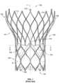
- Fig. 1shows a collapsible stent-supported prosthetic heart valve 100 according to the prior art, the prosthetic heart valve being shown in an expanded condition.
- Prosthetic heart valve 100is designed to replace the function of the native aortic valve of a patient.
- Prosthetic heart valve 100includes a stent 102 which serves as a frame for the valve elements.
- Stent 102extends along a lengthwise or longitudinal axis L from an inflow or annulus end 130 to an outflow or aortic end 132, and includes an annulus section 140 adjacent inflow end 130 and an aortic section 142 adjacent outflow end 132.
- Annulus section 140may be in the form of a cylinder having a substantially constant diameter along its length, and may have a relatively small transverse cross-section in the expanded condition in comparison to the transverse cross-section of aortic section 142.
- a transition section 141may taper outwardly from annulus section 140 to aortic section 142.
- Each of the sections of stent 102includes a plurality of cells 112 formed by interconnected struts 114.
- Each cell 112may include four struts 114 connected together generally in a diamond shape so as to form a cell that may be readily collapsed and expanded. It will be appreciated that a smaller or larger number of struts may be used to form cells having a different shape.
- the cells 112 in each section of stent 102may be connected to one another in one or more annular rows around the stent.
- annulus section 140may have two annular rows of complete cells 112, with the cells in one annular row offset by one-half cell width in the circumferential direction from the cells in the other annular row.
- Aortic section 142 and transition section 141may each have one or more annular rows of complete or partial cells 112.
- the cells in aortic section 142may be larger than the cells in annulus section 140 so as to better enable prosthetic valve 100 to be positioned within the aortic annulus without the structure of stent 102 interfering with blood flow to the coronary arteries.
- stent 102elongates in the direction of longitudinal axis L as the cells collapse when the stent transitions from the expanded condition to the collapsed condition, and shortens in the direction of longitudinal axis L as the stent transitions from the collapsed condition to the expanded condition.
- Stent 102may include one or more retaining elements 118 at outflow end 132, the retaining elements being sized and shaped to cooperate with retaining structures provided on a deployment device (not shown).
- the engagement of retaining elements 118 with the retaining structures on the deployment devicemay help maintain prosthetic heart valve 100 in assembled relationship with the deployment device, minimize longitudinal movement of the prosthetic heart valve relative to the deployment device during unsheathing or resheathing procedures, and help prevent rotation of the prosthetic heart valve relative to the deployment device as the deployment device is advanced to the target location and during deployment.
- One such deployment deviceis described in U.S. Patent Publication No. 2012/0078352 .
- Stent 102may also include a plurality of commissure attachment features 116 for mounting the commissures of the valve assembly to the stent.
- each commissure attachment feature 116may lie at the intersection of four cells 112, two of the cells being adjacent one another in the same annular row, and the other two cells being in different annular rows and lying in end-to-end relationship.
- Commissure attachment features 116may be positioned entirely within annulus section 140 or at the juncture of annulus section 140 and transition section 141, and may include one or more eyelets or apertures which facilitate the suturing of the leaflet commissures to stent 102.
- Stent 102may be formed as a unitary structure, for example, by laser cutting or etching a tube of a superelastic and/or shape-memory metal alloy, such as a nickel-titanium alloy of the type sold under the designation nitinol.
- a unitary structuremay be referred to as a "non-woven" structure in that it is not formed by weaving or winding one or more filaments.
- Prosthetic heart valve 100includes a valve assembly 104 positioned in the annulus section 140 of stent 102.
- Valve assembly 104includes a plurality of leaflets 108 that collectively function as a one way valve by coapting with one another, and a cuff 106 positioned on the luminal surface of stent 102 surrounding leaflets 108.
- As prosthetic heart valve 100is intended to replace the aortic valve (which ordinarily is a tri-leaflet valve), it is shown in Fig. 1 with three leaflets 108. Adjacent leaflets 108 join one another at leaflet commissures. Each of the leaflet commissures may be sutured to a respective one of the three commissure attachment features 116.
- each leaflet 108may be sutured to stent 102 and/or to cuff 106 along a leaflet belly B, indicated with broken lines in Fig. 1 .
- Leaflets 108may be joined to stent 102 and/or to cuff 106 by techniques known in the art other than suturing.
- Above belly Bleaflets 108 are free to move radially inward to coapt with one another along their free edges.
- prosthetic heart valvesmay have more or less than the three leaflets 108 and commissure attachment features 116 shown in Fig. 1 and described above.
- cuff 106is shown in Fig. 1 as being disposed on the luminal or inner surface of annulus section 140, the cuff may be disposed on the abluminal or outer surface of the annulus section, or may cover all or part of either or both of the luminal and abluminal surfaces of the annulus section.
- Cuff 106may be scalloped at the inflow end 130 of stent 102, and may have a zig-zag structure at its outflow end, following certain stent struts 114 up to commissure attachment features 116 and other stent struts closer to the inflow end of the stent at circumferential positions between the commissure attachment features. As is shown in Fig.
- valve assembly 104in one example, the entirety of valve assembly 104, including the leaflet commissures, is positioned in the annulus section 140 of stent 102. When open, leaflets 108 may remain substantially completely within annulus section 140, or they may be designed to extend into transition section 141. In the embodiment shown, substantially the entirety of valve assembly 104 is positioned between the inflow end 130 of stent 102 and commissure attachment features 116, and none of the valve assembly is positioned between the commissure attachment features and the outflow end 132 of the stent.
- prosthetic heart valve 100 described abovemay be used to replace a native heart valve, such as the aortic valve; a surgical heart valve; or a heart valve that has undergone a surgical procedure.
- Prosthetic heart valve 100may be delivered to the desired site (e.g., near the native aortic annulus) using any suitable delivery device.
- prosthetic heart valve 100is disposed inside the delivery device in the collapsed condition.
- the delivery devicemay be introduced into the patient using any known percutaneous procedure, such as a transfemoral, transapical, or transseptal delivery procedure.
- the usermay deploy prosthetic heart valve 100.
- prosthetic heart valve 100expands into secure engagement within the native aortic annulus.
- prosthetic heart valve 100When prosthetic heart valve 100 is properly positioned inside the heart, it works as a one-way valve, allowing blood to flow in one direction and preventing blood from flowing in the opposite direction.
- Fig. 2is a highly schematic transverse cross-sectional illustration taken along line 2-2 of Fig. 2 and showing prosthetic heart valve 100 with leaflets 108 disposed within native valve annulus 250.
- the substantially circular annulus section 140 of stent 102is disposed within a non-circular native valve annulus 250.
- gaps 200are formed between the heart valve and native valve annulus 250. Retrograde blood flow through these gaps and around the outside of the valve assembly 104 of prosthetic heart valve 100 can result in PV leak or regurgitation and other inefficiencies which can reduce cardiac performance.
- Such improper fitmentmay be due to suboptimal native valve annulus geometry, for example, as a result of the calcification of the tissue of native valve annulus 250 or the presence of unresected native leaflets.
- Fig. 3Aillustrates the stent 302 of a prosthetic heart valve according to an aspect of the disclosure.
- Fig. 3Billustrates a prosthetic heart valve 300 that includes the stent 302 of Fig. 3A .
- Stent 302may be similar or identical to stent 102 described above, with certain exceptions.
- the annulus section 340 of stent 302may include three rows of cells 312 instead of two rows, although in some embodiments stent 302 may include only two rows of cells in the annulus section, or any other number of rows of cells.
- commissure attachment features 316 of stent 302are illustrated schematically as open rectangles in Fig.
- the commissure attachment featuresmay have a form similar to commissure attachment features 116 shown in Fig. 1 , or any other suitable form having any number of rows or columns of eyelets and/or eyelets of different sizes and/or shapes positioned in any arrangement on the commissure attachment feature.
- commissure attachment features 316may include a single elongated eyelet extending in a circumferential direction on a proximal end portion of the commissure attachment feature, with two rows and two columns of substantially rectangular-shaped eyelets positioned distally of the elongated eyelet.
- a cuff 306 similar or identical to cuff 106may be positioned on the luminal and/or abluminal surface of stent 302.
- prosthetic heart valve 300may include a valve assembly 304 having a plurality of leaflets, similar or identical to those of valve assembly 104, positioned radially inwardly of cuff 306 and attached to that cuff.
- outer cuff 350may have a substantially rectangular shape and may be wrapped around the circumference of stent 302 at the inflow end of the stent so as to overlap in the longitudinal direction of the stent with cuff 306.
- Outer cuff 350may be a single piece of material having a proximal edge 352, two side edges 354, 356, and a distal edge 358.
- the proximal edge 352 of outer cuff 350is coupled to stent 302 and/or to inner cuff 306 at or near the inflow end of the stent, for example by a continuous line of sutures (not shown), with the side edges 354 and 356 of the outer cuff joined to one another so that retrograde blood flow entering the space between the outer cuff and the inner cuff cannot pass in the retrograde direction beyond the combined cuffs.
- the distal edge 358 of the outer cuffmay be attached to stent 302 and/or to inner cuff 306 at locations that are spaced apart in the circumferential direction.
- the distal edge 358 of outer cuff 350may, for example, be sutured to stent 302 at attachment points S1 located where each cell 312 in the proximalmost row of cells intersects with an adjacent cell in that same row.
- attachment points S1located where each cell 312 in the proximalmost row of cells intersects with an adjacent cell in that same row.
- Retrograde blood flow around the abluminal surface of stent 302may enter the pocket or space between outer cuff 350 and inner cuff 306 via the spaces between adjacent attachment points S1.
- outer cuff 350may tend to billow outwardly, helping to fill any of gaps 200 between the prosthetic heart valve and native valve annulus 250.
- inner cuff 306may be located either on the luminal or abluminal side of stent 302, or on both sides.
- outer cuff 350may comprise multiple pieces of material that, when joined together, form a similar shape and provide similar function as described above for the outer cuff. Also, rather than being formed of a single substantially rectangular piece of material that is wrapped around the circumference of stent 302, outer cuff 350 may be formed as a continuous annular web without side edges 354, 356. Preferably, outer cuff 350 has an axial height measured from its proximal edge 352 to its distal edge 358 that is approximately half the axial height of a cell 312 in the proximalmost row of cells in stent 302 as measured along the major axis of the cell between two of its apices when the cell is in an expanded condition.
- outer cuff 350may have other suitable heights, such as the full axial height of a cell 312 in the proximalmost row of cells, or more or less than the full axial height of a cell 312 in the proximalmost row of cells. Still further, although inner cuff 306 and outer cuff 350 are described above as separate pieces of material joined to stent 302 and to each other, the cuffs may be formed integrally with one another from a single piece of material that is wrapped around the proximal edge of the stent, with the distal edge 358 of the outer portion of the cuff joined to the stent and/or to the inner portion of the cuff at attachment points S1 as described above.
- Inner cuff 306 and outer cuff 350may be formed of the same or different materials, including any suitable biological material or polymer such as, for example, polytetrafluoroethylene (PTFE), ultra-high molecular weight polyethylene (UHMWPE), polyurethane, polyvinyl alcohol, silicone, or combinations thereof.
- PTFEpolytetrafluoroethylene
- UHMWPEultra-high molecular weight polyethylene
- polyurethanepolyvinyl alcohol
- siliconesilicone
- prosthetic heart valve 300may be transitioned into a collapsed condition and loaded onto a delivery device for delivery into a patient.
- Prosthetic heart valve 300may be advanced to the aortic valve of the patient while it is maintained in the collapsed condition, for example by an overlying sheath of the delivery device that radially constrains the prosthetic heart valve.
- the overlying sheathmay be removed from prosthetic heart valve 300, removing the constraining force.
- prosthetic heart valve 300returns to the expanded condition.
- any bloodflows in the retrograde direction around the outside of stent 302, that blood may flow into the space between outer cuff 350 and inner cuff 306.
- Blood flowing into the space between inner cuff 306 and outer cuff 350may result in the outer cuff billowing outwardly to some degree to further seal any remaining spaces between prosthetic heart valve 300 and the native aortic valve annulus, helping to mitigate or eliminate PV leak.
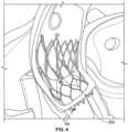
- Fig. 4illustrates a prosthetic heart valve, for example prosthetic heart valve 100 or prosthetic heart valve 300, implanted in the native valve annulus 250 of an aortic valve.
- the inflow end of the prosthetic heart valveis typically positioned between about 3 mm and about 6 mm below native valve annulus 250.
- the prosthetic heart valvewill typically have a sub-annular portion SA that includes about 3 mm to about 6 mm of structure that extends beyond native valve annulus 250 in a direction toward the left ventricle.
- sub-annular portion SAmay extend a distance beyond native valve annulus 250 to help assure full contact around the entire annulus section of the stent.
- the sub-annular portion SAmay not pose any particular problems with the operation of the prosthetic heart valve.
- the sub-annular portion SAmay cause certain undesirable results in the functioning of the prosthetic heart valve.
- outer cuff 350may tend to at least partially fill with blood and billow outwardly to help prevent PV leak.
- the terminal end of the stentwill tend to deflect inwardly more than portions of the stent farther away from the terminal end of the stent.
- the inward deflection of the sub-annular portion SA of stent 302creates an additional mode of loading which may contribute to concerns of stent fatigue. It should be understood that prosthetic heart valves of a particular design are often provided in various sizes to account for the natural variations in size of patients' native heart valves.
- the relatively large prosthetic valvemay experience greater deflection in the sub-annular portion SA of the prosthetic heart valve due to this additional mode of loading, which may result in a greater concern of stent fatigue compared to the relatively small prosthetic valve.
- FIGs. 5A-Billustrate a prosthetic heart valve 400 according to an embodiment of the disclosure which may be identical or substantially identical to prosthetic heart valve 300, with the exception that outer cuff 450 is positioned farther from the inflow end of stent 402 compared to the positioning of outer cuff 350 with respect to the inflow end of stent 302.
- Prosthetic heart valve 400may include a stent 402 forming a plurality of cells 412, and may include a valve assembly 404 including a plurality of leaflets attached to the stent at commissure attachment features 416, an inner cuff 406, and an outer cuff 450. It should be understood that, with the exception of outer cuff 450, the remaining components of prosthetic heart valve 400 may be identical to the corresponding components of prosthetic heart valve 300 described above and are not described in any further detail herein.
- outer cuff 450may have a substantially rectangular shape and may be wrapped around the perimeter of stent 402 near the inflow end of the stent so as to overlap in the longitudinal direction of the stent with inner cuff 406.
- Outer cuff 450may be a single piece of material having a proximal edge 452, a distal edge 458, and two side edges, although the side edges may be omitted if the outer cuff takes the form of a continuous wrap of material.
- outer cuff 450may comprise multiple separate pieces of material that, when joined together, form a similar shape and provide similar function as shown and described herein for the outer cuff.
- Inner cuff 406 and outer cuff 450may be formed of the same or different materials, including any of those described above in connection with inner cuff 306 and outer cuff 350.
- the proximal edge of the outer cuffis coupled to the stent and/or the inner cuff at a spaced distance from the inflow end of the stent toward the outflow end of the stent. As shown in Fig. 5A , this distance may be between about 3 mm and about 5 mm from the inflow edge, which is similar but not necessarily the same as the about 3 mm to about 6 mm length of the sub-annular portion SA.
- the proximal edge 452 of outer cuff 450may be coupled to stent 402 and/or to inner cuff 406, for example by a continuous line of sutures, so that retrograde blood flow entering the space between the outer cuff and the inner cuff cannot pass in the retrograde direction beyond the combined cuffs.
- outer cuff 450includes side edges, those side edges may be coupled to one another prior to, during, or after coupling the outer cuff to stent 402 and/or to inner cuff 406.
- the distal edge 458 of the outer cuffmay be attached to stent 402 and/or to inner cuff 406 at locations that are spaced apart in the circumferential direction, similar to how outer cuff 350 is described and shown in Fig. 3A as being coupled to stent 302 and/or to inner cuff 306.
- the distal edge 458 of outer cuff 450may be sutured to stent 402 at attachment points located where each cell 412 in the proximalmost row of cells intersects with an adjacent cell in that same row.
- the positions of the openings to the one or more pockets formed between outer cuff 450 and inner cuff 406 when prosthetic heart valve 400 is implantedare substantially identical to the positions of the openings to the one or more pockets formed between outer cuff 350 and inner cuff 306 when prosthetic heart valve 300 is implanted.
- the ability for retrograde blood flow around the abluminal surface of stent 402 to enter the pocket(s) or space(s) between outer cuff 450 and inner cuff 406is substantially unchanged compared to prosthetic heart valve 300.
- outer cuff 450 compared to inner cuff 350need not result in a significant change in the ability of the outer cuff of prosthetic heart valve 400 to billow open to mitigate PV leak compared to the outer cuff of prosthetic heart valve 300. At least one reason for this is that the sub-annular portion SA of outer cuff 350 does not significantly contribute to sealing upon entry of blood into the space between the outer cuff and inner cuff 306 when it is positioned beyond native valve annulus 250. In other words, eliminating the sub-annular portion SA of outer cuff 350, effectively resulting in the outer cuff 450 of prosthetic heart valve 400 shown in Figs. 5A-B , need not reduce the ability of the outer cuff to mitigate PV leak.
- outer cuff 450compared to outer cuff 350 need not reduce the ability to mitigate PV leak, but there may be a significant reduction in the forces and/or moments applied on the inflow end of stent 402 in the radially inward direction from blood flowing in the retrograde direction around the abluminal surface of the stent into the space(s) between outer cuff 450 and inner cuff 406.
- the reason for the reduction in thee forcescan be seen in the force diagrams in Figs. 6A and 7A , and the corresponding representations of the resulting stent deflections shown in Figs. 6B and 7B .
- Figs. 6A and 6Bshow that, as blood flows in the retrograde direction R into the space between inner cuff 306 and outer cuff 350, forces F1 act radially inwardly in that area on the inner cuff and thus also the adjacent portions of stent 302, causing an amount of deflection D1.
- Figs. 6Ashows that, as blood flows in the retrograde direction R into the space between inner cuff 306 and outer cuff 350, forces F1 act radially inwardly in that area on the inner cuff and thus also the adjacent portions of stent 302, causing an amount of deflection D1.
- the relatively large deflection of stent 302 in the sub-annular portion SAcaused at least in part by a cantilever effect on the
- Figs. 6A-7Bare not expected to be static due to the pulsatile nature of blood flow. Stated otherwise, as the prosthetic heart valves 300, 400 open and close during the cardiac cycle, the forces and deflections shown in Figs. 6A-7B would be cyclical, occurring while the prosthetic heart valve is in the closed condition and blood attempts to flow in the retrograde direction R between the abluminal surface of the prosthetic valve and the native valve annulus 250. This cyclical nature of the deflection may increase the stresses in stents 302, 402 and cause stent fatigue, which may reduce the overall amount of time during which the prosthetic heart valves 300, 400 are expected to function properly. The larger deflections D1 that may occur in prosthetic heart valve 300 may result in a corresponding shorter lifespan of the prosthetic heart valve compared to that of prosthetic heart valve 400.
- deflections D1 and D2 shown in Figs. 6A-7Bare not intended to be to scale or to otherwise represent actual amounts of deflection, but rather are intended to illustrate schematically that a smaller deflection D2 is expected in stent 402 compared to the larger deflection D1 expected in stent 302.
- a prosthetic heart valve 300'is illustrated that is identical to prosthetic heart valve 300 with one exception. It should be understood that the part numbers in Fig. 8 that are identical to the part numbers in Fig. 3B indicate a similar or identical structure, and thus are not described in any further detail.
- the difference in prosthetic heart valve 300'is found in outer cuff 350'.
- Outer cuff 350'may be generally identical in shape, size, and positioning to outer cuff 350, but may be modified to decrease the available space between the outer cuff 350' and inner cuff 306 that is available to receive retrograde blood flow therebetween. In the particular embodiment illustrated in Fig.
- one or more sutures (or other fasteners) 355'coupled the outer cuff 350' to the inner cuff 306 at positions near the terminal inflow end of the prosthetic heart valve 300'.
- one suture 355'(or one suture line) is provided for each cell 312 in the proximalmost row of cells.
- Each suture 355'(or each suture line) extends from the terminal inflow end of the outer cuff 350', and curves to reach its highest point near a circumferential center of the corresponding cell 312, at which point the suture 355' (or suture line) curves back down toward the terminal inflow end of the outer cuff 350'.
- the suture 355'couples the outer cuff 350' to the inner cuff 306, the space beneath the suture 355' (or suture line) is not available for blood to flow into.
- the suture 355'effectively reduces the available area in which blood may flow, achieving a similar or identical effect without altering the height of outer cuff 350.
- any retrograde blood flowing into the available space between outer cuff 350' and inner cuff 306will not be able to flow beyond the sutures 355', minimizing the amount of deflection that may be expected at the terminal inflow end of stent 302.
- a single suturemay form the entire suture line 355' extending around the circumference of the stent 302, although more than one suture may be used to form the entirety of the suture line 355'.
- each suture 355'may generally axially align with the proximal apex of a cell 312 in the proximalmost row of cells.
- the sutures 355'may be circumferentially offset compared to the embodiment illustrated in Fig. 8 . This curved or scalloped shape, however, is not required.
- a substantially straight suture or suture linemay extend circumferentially around stent 312, attaching the outer cuff 350' to the inner cuff 306 at a point between about 3 mm and about 5 mm or about 6 mm from the inflow end of stent 302.
- sutures 355'are illustrated in Fig. 8 as being substantially continuous around the circumference of stent 302, but this is not required either.
- sutures 355'may be strategically positioned to couple outer cuff 350' to inner cuff 306 at positions expected to be prone to the greatest amount of deflection.
- sutures 355'may be provided on the inflow end of outer cuff 350' in positions axially aligned with, or axially adjacent to, commissures attachment features 316.
- the areas of inner cuff 306 that are aligned with commissure attachment features 316may be relatively high pressure areas, and thus the portions of the terminal inflow end of stent 302 that are axially aligned with (or axially adjacent to) the commissure attachment features 316 may be most likely to experience the undesirable deflection described above.
- reducing the available space between outer cuff 350' and inner cuff 306 at positions axially aligned with, or axially adjacent to, commissure attachment features 316may provide similar functionality with fewer sutures 355' (or less total suture material) required.
- a prosthetic heart valve substantially similar to prosthetic heart valves 300' and/or 400may be used to replace the functioning of a native pulmonary valve.
- the concepts described above in connection with the structure of outer cuff 350' and/or the positioning of outer cuff 450 relative to a native valve annulusmay be applied to prosthetic heart valves intended to replace the functioning of either the native mitral valve or native tricuspid valve.
- the configuration of outer cuff 350' and/or outer cuff 450 described abovemay be most useful in prosthetic heart valves that replace the functioning of the native valve of the left heart, as pressures involved with pumping blood in the left heart are typically significantly larger than forces at the valves of the right heart.
Landscapes
- Health & Medical Sciences (AREA)
- Engineering & Computer Science (AREA)
- Biomedical Technology (AREA)
- Cardiology (AREA)
- Oral & Maxillofacial Surgery (AREA)
- Transplantation (AREA)
- Heart & Thoracic Surgery (AREA)
- Vascular Medicine (AREA)
- Life Sciences & Earth Sciences (AREA)
- Animal Behavior & Ethology (AREA)
- General Health & Medical Sciences (AREA)
- Public Health (AREA)
- Veterinary Medicine (AREA)
- Prostheses (AREA)
Description
- This application claims the benefit of the filing date of
United States Provisional Patent Application No. 62/784,923 filed December 26, 2018 - The present disclosure relates to heart valve replacement and, in particular, to collapsible prosthetic heart valves. More particularly, the present disclosure relates to collapsible prosthetic transcatheter heart valves that minimize or reduce paravalvular leaks.
- Prosthetic heart valves that are collapsible to a relatively small circumferential size can be delivered into a patient less invasively than valves that are not collapsible. For example, a collapsible valve may be delivered into a patient via a tube-like delivery apparatus such as a catheter, a trocar, a laparoscopic instrument, or the like. This collapsibility can avoid the need for a more invasive procedure such as full open-chest, open-heart surgery.
- Collapsible prosthetic heart valves typically take the form of a valve structure mounted on a stent. There are two common types of stents on which the valve structures are ordinarily mounted: a self-expanding stent and a balloon-expandable stent. To load such valves into a delivery apparatus and deliver them into a patient, the valve is first collapsed or crimped to reduce its circumferential size. An example of such valves is disclosed in
WO2015/175524A1 . - When a collapsed prosthetic valve has reached the desired implant site in the patient (e.g., at or near the annulus of the patient's heart valve that is to be replaced by the prosthetic valve), the prosthetic valve can be deployed or released from the delivery apparatus and re-expanded to full operating size. For balloon-expandable valves, this generally involves releasing the valve, assuring its proper location, and then expanding a balloon positioned within the valve stent. For self-expanding valves, on the other hand, the stent automatically expands as a sheath covering the valve is withdrawn.
- After implantation, imperfect sealing between the prosthetic valve and the native tissue at the site of implantation may cause complications such as paravalvular leakage ("PV leak") in which retrograde blood flows through one or more gaps formed between the structure of the implanted valve and cardiac tissue as a result of the imperfect sealing.
- According to one aspect of the disclosure, a prosthetic heart valve for replacing a native valve includes a stent extending in a longitudinal direction from an inflow end to an outflow end. A valve assembly may be disposed within the stent. A first cuff may be annularly disposed adjacent the stent. A second cuff may have a proximal edge facing toward the inflow end of the stent and a distal edge facing toward the outflow end of the stent. The second cuff may be annularly disposed about the stent radially outward of the first cuff. The distal edge of the second cuff may be coupled to at least one of the first cuff and the stent at a plurality of locations spaced apart in a circumferential direction of the stent to form at least one pocket between the first cuff and the second cuff. The proximal edge of the second cuff may be coupled to at least one of the first cuff and the stent at a spaced distance from the inflow end of the stent.
- According to another aspect of the disclosure, a method of implanting a prosthetic heart valve into a valve annulus of a patient may include introducing the prosthetic heart valve into the valve annulus of the patient. The prosthetic heart valve may include a stent, a valve assembly disposed within the stent, a first cuff annularly disposed adjacent the stent, and a second cuff annularly disposed on an exterior of the stent radially outward of the first cuff. The method may include positioning the prosthetic heart valve in the valve annulus of the patient so that a sub-annular portion of the stent extends beyond the native valve annulus so that the sub-annular portion of the stent is not in direct contact with the native valve annulus. The sub-annular portion of the stent includes an inflow end of the stent. A portion of the second cuff may be in direct contact with the native valve annulus. The sub-annular portion of the stent is uncovered by the second cuff.
- Various embodiments of the presently disclosed prosthetic heart valve may be more fully understood with reference to the following detailed description when read with the accompanying drawings, in which:
Fig. 1 is a front view of a collapsible prosthetic heart valve according to the prior art, shown in an expanded condition;Fig. 2 is a highly schematic transverse cross-sectional view of the prior art prosthetic heart valve taken along line 2-2 ofFig. 1 and implanted in a patient;Fig. 3A is a schematic developed view of a stent with an outer cuff in an expanded condition according to an embodiment of the disclosure;Fig. 3B is a perspective view of a prosthetic heart valve having the stent and outer cuff ofFig. 3A ;Fig. 4 is a cutaway schematic view of a prosthetic heart valve implanted in a native aortic valve;Fig. 5A is a schematic front view of a collapsible prosthetic heart valve according to another aspect of the disclosure;Fig. 5B is a schematic perspective view of the prosthetic heart valve ofFig. 5A ;Fig. 6A is a diagram of forces acting on the stent of the prosthetic heart valve ofFig. 3B ;Fig. 6B is a highly schematic representation of deflection of the stent of the prosthetic heart valve ofFig. 3B due to the forces diagrammed inFig. 6A ;Fig. 7A is a diagram of forces acting on the stent of the prosthetic heart valve ofFig. 5A ; andFig. 7B is a highly schematic representation of deflection of the stent of the prosthetic heart valve ofFig. 5A due to the forces diagrammed inFig. 7A .Fig. 8 is a perspective view of a prosthetic heart valve according to another aspect of the disclosure.- As used herein in connection with a prosthetic heart valve, the term "inflow end" refers to the end of the heart valve through which blood enters when the valve is functioning as intended, and the term "outflow end" refers to the end of the heart valve through which blood exits when the valve is functioning as intended. As used herein, the term "proximal" refers to the inflow end of a prosthetic heart valve or to elements of a prosthetic heart valve that are relatively close to the inflow end, and the term "distal" refers to the outflow end of a prosthetic heart valve or to elements of a prosthetic heart valve that are relatively close to the outflow end. As used herein, the terms "generally," "substantially," and "about" are intended to mean that slight deviations from absolute are included within the scope of the term so modified. Like numbers refer to similar or identical elements throughout. When used herein in the context of a prosthetic heart valve, or a component thereof, the lengthwise or axial direction refers to a direction parallel to a longitudinal axis passing through the center of the stent or heart valve from the inflow end to the outflow end. When used herein in the context of a prosthetic heart valve, or a component thereof, the circumferential direction refers to a direction extending along the circumference of the prosthetic heart valve.
Fig. 1 shows a collapsible stent-supportedprosthetic heart valve 100 according to the prior art, the prosthetic heart valve being shown in an expanded condition.Prosthetic heart valve 100 is designed to replace the function of the native aortic valve of a patient.Prosthetic heart valve 100 includes astent 102 which serves as a frame for the valve elements.Stent 102 extends along a lengthwise or longitudinal axis L from an inflow orannulus end 130 to an outflow oraortic end 132, and includes anannulus section 140adjacent inflow end 130 and anaortic section 142adjacent outflow end 132.Annulus section 140 may be in the form of a cylinder having a substantially constant diameter along its length, and may have a relatively small transverse cross-section in the expanded condition in comparison to the transverse cross-section ofaortic section 142. Atransition section 141 may taper outwardly fromannulus section 140 toaortic section 142. Each of the sections ofstent 102 includes a plurality ofcells 112 formed byinterconnected struts 114. Eachcell 112 may include fourstruts 114 connected together generally in a diamond shape so as to form a cell that may be readily collapsed and expanded. It will be appreciated that a smaller or larger number of struts may be used to form cells having a different shape. Thecells 112 in each section ofstent 102 may be connected to one another in one or more annular rows around the stent. For example, as shown inFig. 1 ,annulus section 140 may have two annular rows ofcomplete cells 112, with the cells in one annular row offset by one-half cell width in the circumferential direction from the cells in the other annular row.Aortic section 142 andtransition section 141 may each have one or more annular rows of complete orpartial cells 112. The cells inaortic section 142 may be larger than the cells inannulus section 140 so as to better enableprosthetic valve 100 to be positioned within the aortic annulus without the structure ofstent 102 interfering with blood flow to the coronary arteries. At least partly due to the shape ofcells 112,stent 102 elongates in the direction of longitudinal axis L as the cells collapse when the stent transitions from the expanded condition to the collapsed condition, and shortens in the direction of longitudinal axis L as the stent transitions from the collapsed condition to the expanded condition.Stent 102 may include one ormore retaining elements 118 atoutflow end 132, the retaining elements being sized and shaped to cooperate with retaining structures provided on a deployment device (not shown). The engagement of retainingelements 118 with the retaining structures on the deployment device may help maintainprosthetic heart valve 100 in assembled relationship with the deployment device, minimize longitudinal movement of the prosthetic heart valve relative to the deployment device during unsheathing or resheathing procedures, and help prevent rotation of the prosthetic heart valve relative to the deployment device as the deployment device is advanced to the target location and during deployment. One such deployment device is described inU.S. Patent Publication No. 2012/0078352 .Stent 102 may also include a plurality of commissure attachment features 116 for mounting the commissures of the valve assembly to the stent. As can be seen inFig. 1 , eachcommissure attachment feature 116 may lie at the intersection of fourcells 112, two of the cells being adjacent one another in the same annular row, and the other two cells being in different annular rows and lying in end-to-end relationship. Commissure attachment features 116 may be positioned entirely withinannulus section 140 or at the juncture ofannulus section 140 andtransition section 141, and may include one or more eyelets or apertures which facilitate the suturing of the leaflet commissures tostent 102.Stent 102 may be formed as a unitary structure, for example, by laser cutting or etching a tube of a superelastic and/or shape-memory metal alloy, such as a nickel-titanium alloy of the type sold under the designation nitinol. Such a unitary structure may be referred to as a "non-woven" structure in that it is not formed by weaving or winding one or more filaments.Prosthetic heart valve 100 includes avalve assembly 104 positioned in theannulus section 140 ofstent 102.Valve assembly 104 includes a plurality ofleaflets 108 that collectively function as a one way valve by coapting with one another, and acuff 106 positioned on the luminal surface ofstent 102 surroundingleaflets 108. Asprosthetic heart valve 100 is intended to replace the aortic valve (which ordinarily is a tri-leaflet valve), it is shown inFig. 1 with threeleaflets 108.Adjacent leaflets 108 join one another at leaflet commissures. Each of the leaflet commissures may be sutured to a respective one of the three commissure attachment features 116. Between the leaflet commissures, eachleaflet 108 may be sutured tostent 102 and/or to cuff 106 along a leaflet belly B, indicated with broken lines inFig. 1 .Leaflets 108 may be joined tostent 102 and/or to cuff 106 by techniques known in the art other than suturing. Above belly B,leaflets 108 are free to move radially inward to coapt with one another along their free edges. Whenprosthetic heart valve 100 is implanted in the native aortic valve annulus, blood flows in an antegrade direction frominflow end 130,past leaflets 108, and towardoutflow end 132. This occurs when the pressure in the left ventricle is greater than the pressure in the aorta, forcingleaflets 108 to open. When the pressure in the aorta is greater than the pressure in the left ventricle,leaflets 108 are forced closed and coapt with one another along their free edges, blocking blood from flowing throughprosthetic heart valve 100 in a retrograde direction fromoutflow end 132 toinflow end 130. It will be appreciated that prosthetic heart valves according to aspects of the present disclosure may have more or less than the threeleaflets 108 and commissure attachment features 116 shown inFig. 1 and described above.- Although
cuff 106 is shown inFig. 1 as being disposed on the luminal or inner surface ofannulus section 140, the cuff may be disposed on the abluminal or outer surface of the annulus section, or may cover all or part of either or both of the luminal and abluminal surfaces of the annulus section.Cuff 106 may be scalloped at theinflow end 130 ofstent 102, and may have a zig-zag structure at its outflow end, following certain stent struts 114 up to commissure attachment features 116 and other stent struts closer to the inflow end of the stent at circumferential positions between the commissure attachment features. As is shown inFig. 1 , in one example, the entirety ofvalve assembly 104, including the leaflet commissures, is positioned in theannulus section 140 ofstent 102. When open,leaflets 108 may remain substantially completely withinannulus section 140, or they may be designed to extend intotransition section 141. In the embodiment shown, substantially the entirety ofvalve assembly 104 is positioned between theinflow end 130 ofstent 102 and commissure attachment features 116, and none of the valve assembly is positioned between the commissure attachment features and theoutflow end 132 of the stent. - In operation,
prosthetic heart valve 100 described above may be used to replace a native heart valve, such as the aortic valve; a surgical heart valve; or a heart valve that has undergone a surgical procedure.Prosthetic heart valve 100 may be delivered to the desired site (e.g., near the native aortic annulus) using any suitable delivery device. During delivery,prosthetic heart valve 100 is disposed inside the delivery device in the collapsed condition. The delivery device may be introduced into the patient using any known percutaneous procedure, such as a transfemoral, transapical, or transseptal delivery procedure. Once the delivery device has reached the target site, the user may deployprosthetic heart valve 100. Upon deployment,prosthetic heart valve 100 expands into secure engagement within the native aortic annulus. Whenprosthetic heart valve 100 is properly positioned inside the heart, it works as a one-way valve, allowing blood to flow in one direction and preventing blood from flowing in the opposite direction. Fig. 2 is a highly schematic transverse cross-sectional illustration taken along line 2-2 ofFig. 2 and showingprosthetic heart valve 100 withleaflets 108 disposed withinnative valve annulus 250. As can be seen, the substantiallycircular annulus section 140 ofstent 102 is disposed within a non-circularnative valve annulus 250. At certain locations around the perimeter ofprosthetic heart valve 100,gaps 200 are formed between the heart valve andnative valve annulus 250. Retrograde blood flow through these gaps and around the outside of thevalve assembly 104 ofprosthetic heart valve 100 can result in PV leak or regurgitation and other inefficiencies which can reduce cardiac performance. Such improper fitment may be due to suboptimal native valve annulus geometry, for example, as a result of the calcification of the tissue ofnative valve annulus 250 or the presence of unresected native leaflets.Fig. 3A illustrates thestent 302 of a prosthetic heart valve according to an aspect of the disclosure.Fig. 3B illustrates aprosthetic heart valve 300 that includes thestent 302 ofFig. 3A .Stent 302 may be similar or identical tostent 102 described above, with certain exceptions. For example, theannulus section 340 ofstent 302 may include three rows ofcells 312 instead of two rows, although in someembodiments stent 302 may include only two rows of cells in the annulus section, or any other number of rows of cells. Although commissure attachment features 316 ofstent 302 are illustrated schematically as open rectangles inFig. 3A , the commissure attachment features may have a form similar to commissure attachment features 116 shown inFig. 1 , or any other suitable form having any number of rows or columns of eyelets and/or eyelets of different sizes and/or shapes positioned in any arrangement on the commissure attachment feature. For example, as shown inFig. 3B , commissure attachment features 316 may include a single elongated eyelet extending in a circumferential direction on a proximal end portion of the commissure attachment feature, with two rows and two columns of substantially rectangular-shaped eyelets positioned distally of the elongated eyelet. Acuff 306 similar or identical tocuff 106 may be positioned on the luminal and/or abluminal surface ofstent 302. Rather than a scalloped inflow end as withcuff 106, however,cuff 306 may have a straight inflow end. As shown inFig. 3B ,prosthetic heart valve 300 may include avalve assembly 304 having a plurality of leaflets, similar or identical to those ofvalve assembly 104, positioned radially inwardly ofcuff 306 and attached to that cuff.- In order to help minimize or eliminate PV leak, for example through the
gaps 200 shown inFig. 2 , additional material may be coupled to the exterior ofstent 302 as anouter cuff 350. In the illustrated example,outer cuff 350 may have a substantially rectangular shape and may be wrapped around the circumference ofstent 302 at the inflow end of the stent so as to overlap in the longitudinal direction of the stent withcuff 306.Outer cuff 350 may be a single piece of material having aproximal edge 352, twoside edges distal edge 358. Preferably, theproximal edge 352 ofouter cuff 350 is coupled tostent 302 and/or toinner cuff 306 at or near the inflow end of the stent, for example by a continuous line of sutures (not shown), with the side edges 354 and 356 of the outer cuff joined to one another so that retrograde blood flow entering the space between the outer cuff and the inner cuff cannot pass in the retrograde direction beyond the combined cuffs. In order to allow retrograde blood flow to enter the space betweenouter cuff 350 andinner cuff 306, thedistal edge 358 of the outer cuff may be attached tostent 302 and/or toinner cuff 306 at locations that are spaced apart in the circumferential direction. Thedistal edge 358 ofouter cuff 350 may, for example, be sutured tostent 302 at attachment points S1 located where eachcell 312 in the proximalmost row of cells intersects with an adjacent cell in that same row. In the illustrated example, since there are ninecells 312 in the proximalmost row, there are nine separate attachment points S1 at which thedistal edge 358 ofouter cuff 350 is sutured or otherwise attached tostent 302. Retrograde blood flow around the abluminal surface ofstent 302 may enter the pocket or space betweenouter cuff 350 andinner cuff 306 via the spaces between adjacent attachment points S1. Once retrograde blood flow enters this space,outer cuff 350 may tend to billow outwardly, helping to fill any ofgaps 200 between the prosthetic heart valve andnative valve annulus 250. Although the foregoing description uses the term "inner" in connection withcuff 306, that is merely intended to indicate thatcuff 306 is positioned radially inward ofouter cuff 350.Inner cuff 306 may be located either on the luminal or abluminal side ofstent 302, or on both sides. - Although described as a single piece of material above,
outer cuff 350 may comprise multiple pieces of material that, when joined together, form a similar shape and provide similar function as described above for the outer cuff. Also, rather than being formed of a single substantially rectangular piece of material that is wrapped around the circumference ofstent 302,outer cuff 350 may be formed as a continuous annular web without side edges 354, 356. Preferably,outer cuff 350 has an axial height measured from itsproximal edge 352 to itsdistal edge 358 that is approximately half the axial height of acell 312 in the proximalmost row of cells instent 302 as measured along the major axis of the cell between two of its apices when the cell is in an expanded condition. However,outer cuff 350 may have other suitable heights, such as the full axial height of acell 312 in the proximalmost row of cells, or more or less than the full axial height of acell 312 in the proximalmost row of cells. Still further, althoughinner cuff 306 andouter cuff 350 are described above as separate pieces of material joined tostent 302 and to each other, the cuffs may be formed integrally with one another from a single piece of material that is wrapped around the proximal edge of the stent, with thedistal edge 358 of the outer portion of the cuff joined to the stent and/or to the inner portion of the cuff at attachment points S1 as described above. With this configuration, theproximal edge 352 ofouter cuff 350 does not need to be sutured tostent 302, although it still may be preferable to provide such attachment.Inner cuff 306 andouter cuff 350 may be formed of the same or different materials, including any suitable biological material or polymer such as, for example, polytetrafluoroethylene (PTFE), ultra-high molecular weight polyethylene (UHMWPE), polyurethane, polyvinyl alcohol, silicone, or combinations thereof. - In operation,
prosthetic heart valve 300 may be transitioned into a collapsed condition and loaded onto a delivery device for delivery into a patient.Prosthetic heart valve 300 may be advanced to the aortic valve of the patient while it is maintained in the collapsed condition, for example by an overlying sheath of the delivery device that radially constrains the prosthetic heart valve. Once at the desired location, such as the native aortic valve, the overlying sheath may be removed fromprosthetic heart valve 300, removing the constraining force. In the absence of any constraining forces,prosthetic heart valve 300 returns to the expanded condition. During normal operation, if any blood flows in the retrograde direction around the outside ofstent 302, that blood may flow into the space betweenouter cuff 350 andinner cuff 306. Blood flowing into the space betweeninner cuff 306 andouter cuff 350 may result in the outer cuff billowing outwardly to some degree to further seal any remaining spaces betweenprosthetic heart valve 300 and the native aortic valve annulus, helping to mitigate or eliminate PV leak. Fig. 4 illustrates a prosthetic heart valve, for exampleprosthetic heart valve 100 orprosthetic heart valve 300, implanted in thenative valve annulus 250 of an aortic valve. As shown inFig. 4 , the inflow end of the prosthetic heart valve is typically positioned between about 3 mm and about 6 mm belownative valve annulus 250. In other words, when the prosthetic heart valve replaces the function of a native aortic valve, the prosthetic heart valve will typically have a sub-annular portion SA that includes about 3 mm to about 6 mm of structure that extends beyondnative valve annulus 250 in a direction toward the left ventricle. It may be desirable to have sub-annular portion SA extend a distance beyondnative valve annulus 250 to help assure full contact around the entire annulus section of the stent. Forprosthetic heart valve 100, which does not include a second outer cuff as described in connection withprosthetic heart valve 300, the sub-annular portion SA may not pose any particular problems with the operation of the prosthetic heart valve. However, forprosthetic heart valve 300, the sub-annular portion SA may cause certain undesirable results in the functioning of the prosthetic heart valve. As described above,outer cuff 350 may tend to at least partially fill with blood and billow outwardly to help prevent PV leak. However, as blood flows into the space betweenouter cuff 350 andinner cuff 306, that blood flow may apply pressure to the inner cuff in a direction radially inwardly toward the center longitudinal axis ofprosthetic heart valve 300. Because sub-annular portion SA is at the terminal (inflow) end of the stent, the portions ofinner cuff 306 andstent 302 that are within the sub-annular portion ofprosthetic heart valve 300 are essentially cantilevered. Thus, when retrograde blood flow enters betweenouter cuff 350 andinner cuff 306 and applies pressure in a radially inward direction on the inner cuff, the portion of sub-annular portion SA closest to the terminal (inflow) end of the stent is subject to the largest moment. Thus, the terminal end of the stent will tend to deflect inwardly more than portions of the stent farther away from the terminal end of the stent. The inward deflection of the sub-annular portion SA ofstent 302 creates an additional mode of loading which may contribute to concerns of stent fatigue. It should be understood that prosthetic heart valves of a particular design are often provided in various sizes to account for the natural variations in size of patients' native heart valves. Given two prosthetic heart valves having the same design asprosthetic heart valve 300, with the exception that one of the prosthetic heart valves is larger than the other, the relatively large prosthetic valve may experience greater deflection in the sub-annular portion SA of the prosthetic heart valve due to this additional mode of loading, which may result in a greater concern of stent fatigue compared to the relatively small prosthetic valve.- In order to reduce the concern of additional stent fatigue due to blood flowing in the retrograde direction into the space between
outer cuff 350 andinner cuff 306, without changing the positioning ofprosthetic heart valve 300 relative tonative valve annulus 250, the outer cuff may be provided in a modified or elevated position relative tostent 302.Figs. 5A-B illustrate aprosthetic heart valve 400 according to an embodiment of the disclosure which may be identical or substantially identical toprosthetic heart valve 300, with the exception thatouter cuff 450 is positioned farther from the inflow end ofstent 402 compared to the positioning ofouter cuff 350 with respect to the inflow end ofstent 302.Prosthetic heart valve 400 may include astent 402 forming a plurality ofcells 412, and may include avalve assembly 404 including a plurality of leaflets attached to the stent at commissure attachment features 416, aninner cuff 406, and anouter cuff 450. It should be understood that, with the exception ofouter cuff 450, the remaining components ofprosthetic heart valve 400 may be identical to the corresponding components ofprosthetic heart valve 300 described above and are not described in any further detail herein. - Although the position of
outer cuff 450 relative to the remainder ofprosthetic heart valve 400 is different than the position ofouter cuff 350 relative to the remainder ofprosthetic heart valve 300, the outer cuffs themselves may otherwise be substantially the same. For example,outer cuff 450 may have a substantially rectangular shape and may be wrapped around the perimeter ofstent 402 near the inflow end of the stent so as to overlap in the longitudinal direction of the stent withinner cuff 406.Outer cuff 450 may be a single piece of material having aproximal edge 452, adistal edge 458, and two side edges, although the side edges may be omitted if the outer cuff takes the form of a continuous wrap of material. However, as withouter cuff 350,outer cuff 450 may comprise multiple separate pieces of material that, when joined together, form a similar shape and provide similar function as shown and described herein for the outer cuff.Inner cuff 406 andouter cuff 450 may be formed of the same or different materials, including any of those described above in connection withinner cuff 306 andouter cuff 350. - Rather than coupling
proximal edge 452 tostent 402 and/orinner cuff 406 at or near the inflow edge of the stent, the proximal edge of the outer cuff is coupled to the stent and/or the inner cuff at a spaced distance from the inflow end of the stent toward the outflow end of the stent. As shown inFig. 5A , this distance may be between about 3 mm and about 5 mm from the inflow edge, which is similar but not necessarily the same as the about 3 mm to about 6 mm length of the sub-annular portion SA. - As with
outer cuff 350, theproximal edge 452 ofouter cuff 450 may be coupled tostent 402 and/or toinner cuff 406, for example by a continuous line of sutures, so that retrograde blood flow entering the space between the outer cuff and the inner cuff cannot pass in the retrograde direction beyond the combined cuffs. Ifouter cuff 450 includes side edges, those side edges may be coupled to one another prior to, during, or after coupling the outer cuff tostent 402 and/or toinner cuff 406. In order to allow retrograde blood flow to enter the space betweenouter cuff 450 andinner cuff 406, thedistal edge 458 of the outer cuff may be attached tostent 402 and/or toinner cuff 406 at locations that are spaced apart in the circumferential direction, similar to howouter cuff 350 is described and shown inFig. 3A as being coupled tostent 302 and/or toinner cuff 306. For example, thedistal edge 458 ofouter cuff 450 may be sutured tostent 402 at attachment points located where eachcell 412 in the proximalmost row of cells intersects with an adjacent cell in that same row. In the illustrated example, since there are ninecells 412 in the proximalmost row, there are nine separate attachment points at which thedistal edge 458 ofouter cuff 450 is sutured or otherwise attached tostent 402. Comparing theouter cuff 350 ofprosthetic heart valve 300 shown inFig. 3B to theouter cuff 450 ofprosthetic heart valve 400 shown inFigs. 5A-B , it should be understood that the attachment of the distal edges of the outer cuffs to the respective stents are substantially identical in terms of positioning, with the main difference being thatouter cuff 450 has a smaller dimension between itsproximal edge 452 and itsdistal edge 458 compared toouter cuff 350. As a result, the positions of the openings to the one or more pockets formed betweenouter cuff 450 andinner cuff 406 whenprosthetic heart valve 400 is implanted are substantially identical to the positions of the openings to the one or more pockets formed betweenouter cuff 350 andinner cuff 306 whenprosthetic heart valve 300 is implanted. Thus, the ability for retrograde blood flow around the abluminal surface ofstent 402 to enter the pocket(s) or space(s) betweenouter cuff 450 andinner cuff 406 is substantially unchanged compared toprosthetic heart valve 300. Further, it should be understood that the different dimensions and/or spacing ofouter cuff 450 compared toinner cuff 350 need not result in a significant change in the ability of the outer cuff ofprosthetic heart valve 400 to billow open to mitigate PV leak compared to the outer cuff ofprosthetic heart valve 300. At least one reason for this is that the sub-annular portion SA ofouter cuff 350 does not significantly contribute to sealing upon entry of blood into the space between the outer cuff andinner cuff 306 when it is positioned beyondnative valve annulus 250. In other words, eliminating the sub-annular portion SA ofouter cuff 350, effectively resulting in theouter cuff 450 ofprosthetic heart valve 400 shown inFigs. 5A-B , need not reduce the ability of the outer cuff to mitigate PV leak. - As noted above, the different position and/or geometry of
outer cuff 450 compared toouter cuff 350 need not reduce the ability to mitigate PV leak, but there may be a significant reduction in the forces and/or moments applied on the inflow end ofstent 402 in the radially inward direction from blood flowing in the retrograde direction around the abluminal surface of the stent into the space(s) betweenouter cuff 450 andinner cuff 406. The reason for the reduction in thee forces can be seen in the force diagrams inFigs. 6A and7A , and the corresponding representations of the resulting stent deflections shown inFigs. 6B and7B . Figs. 6A and 6B show that, as blood flows in the retrograde direction R into the space betweeninner cuff 306 andouter cuff 350, forces F1 act radially inwardly in that area on the inner cuff and thus also the adjacent portions ofstent 302, causing an amount of deflection D1. The relatively large deflection ofstent 302 in the sub-annular portion SA, caused at least in part by a cantilever effect on the free inflow end of the stent, is illustrated by the diagram ofFig. 6A . On the other hand, as shown inFigs. 7A-7B , the same retrograde blood flow applies radially inward force F2 over the portion ofstent 402 spaced away from the terminal inflow edge, resulting in a reduced moment and lessened cantilever effect. While forces F2 may still cause some amount of deflection D2 in the proximalmost end ofstent 402, the omission of radial inward forces being applied directly to the sub-annular portion SA of the stent results in a relatively small deflection compared to the deflection D1 expected instent 302 when the remaining conditions are the same.- It should be understood that the forces and deflections shown in
Figs. 6A-7B are not expected to be static due to the pulsatile nature of blood flow. Stated otherwise, as theprosthetic heart valves Figs. 6A-7B would be cyclical, occurring while the prosthetic heart valve is in the closed condition and blood attempts to flow in the retrograde direction R between the abluminal surface of the prosthetic valve and thenative valve annulus 250. This cyclical nature of the deflection may increase the stresses instents prosthetic heart valves prosthetic heart valve 300 may result in a corresponding shorter lifespan of the prosthetic heart valve compared to that ofprosthetic heart valve 400. - It should be understood that the deflections D1 and D2 shown in
Figs. 6A-7B are not intended to be to scale or to otherwise represent actual amounts of deflection, but rather are intended to illustrate schematically that a smaller deflection D2 is expected instent 402 compared to the larger deflection D1 expected instent 302. - It may be possible to achieve similar or the same results of maintaining a suitable level of PV leak mitigation while reducing deflection-induced stent fatigue in manners other than that described in connection with
Figs. 5A-B . - Referring now to
Fig. 8 , a prosthetic heart valve 300' is illustrated that is identical toprosthetic heart valve 300 with one exception. It should be understood that the part numbers inFig. 8 that are identical to the part numbers inFig. 3B indicate a similar or identical structure, and thus are not described in any further detail. The difference in prosthetic heart valve 300' is found in outer cuff 350'. Outer cuff 350' may be generally identical in shape, size, and positioning toouter cuff 350, but may be modified to decrease the available space between the outer cuff 350' andinner cuff 306 that is available to receive retrograde blood flow therebetween. In the particular embodiment illustrated inFig. 8 , one or more sutures (or other fasteners) 355' coupled the outer cuff 350' to theinner cuff 306 at positions near the terminal inflow end of the prosthetic heart valve 300'. As illustrated, one suture 355' (or one suture line) is provided for eachcell 312 in the proximalmost row of cells. Each suture 355' (or each suture line) extends from the terminal inflow end of the outer cuff 350', and curves to reach its highest point near a circumferential center of thecorresponding cell 312, at which point the suture 355' (or suture line) curves back down toward the terminal inflow end of the outer cuff 350'. Because the suture 355' couples the outer cuff 350' to theinner cuff 306, the space beneath the suture 355' (or suture line) is not available for blood to flow into. In other words, rather than physically shortening the outer cuff 350' to achieve a structure similar toouter cuff 450, the suture 355' effectively reduces the available area in which blood may flow, achieving a similar or identical effect without altering the height ofouter cuff 350. Thus, any retrograde blood flowing into the available space between outer cuff 350' andinner cuff 306 will not be able to flow beyond the sutures 355', minimizing the amount of deflection that may be expected at the terminal inflow end ofstent 302. It should be understood that a single suture may form the entire suture line 355' extending around the circumference of thestent 302, although more than one suture may be used to form the entirety of the suture line 355'. - In the particular embodiment of outer cuff 350' illustrated in
Fig. 8 , the peak of each suture 355' (or suture line) may generally axially align with the proximal apex of acell 312 in the proximalmost row of cells. However, such alignment is not required, and the sutures 355' (or suture line) may be circumferentially offset compared to the embodiment illustrated inFig. 8 . This curved or scalloped shape, however, is not required. For example, a substantially straight suture or suture line may extend circumferentially aroundstent 312, attaching the outer cuff 350' to theinner cuff 306 at a point between about 3 mm and about 5 mm or about 6 mm from the inflow end ofstent 302. Still further, sutures 355' are illustrated inFig. 8 as being substantially continuous around the circumference ofstent 302, but this is not required either. For example, sutures 355' may be strategically positioned to couple outer cuff 350' toinner cuff 306 at positions expected to be prone to the greatest amount of deflection. In one example, sutures 355' may be provided on the inflow end of outer cuff 350' in positions axially aligned with, or axially adjacent to, commissures attachment features 316. The areas ofinner cuff 306 that are aligned with commissure attachment features 316 may be relatively high pressure areas, and thus the portions of the terminal inflow end ofstent 302 that are axially aligned with (or axially adjacent to) the commissure attachment features 316 may be most likely to experience the undesirable deflection described above. Thus, reducing the available space between outer cuff 350' andinner cuff 306 at positions axially aligned with, or axially adjacent to, commissure attachment features 316 may provide similar functionality with fewer sutures 355' (or less total suture material) required. - A prosthetic heart valve substantially similar to prosthetic heart valves 300' and/or 400 may be used to replace the functioning of a native pulmonary valve. Similarly, the concepts described above in connection with the structure of outer cuff 350' and/or the positioning of
outer cuff 450 relative to a native valve annulus may be applied to prosthetic heart valves intended to replace the functioning of either the native mitral valve or native tricuspid valve. Despite these options, the configuration of outer cuff 350' and/orouter cuff 450 described above may be most useful in prosthetic heart valves that replace the functioning of the native valve of the left heart, as pressures involved with pumping blood in the left heart are typically significantly larger than forces at the valves of the right heart. However, it should also be understood that modifications may be appropriate if being used for a different valve. For example, if the concepts described above were implemented in a prosthetic mitral valve, certain elements may appropriately be modified to account for the different anatomy in the mitral valve compared to the aortic valve. - Features of one embodiment described above may be combined with features of other embodiments described above.
Claims (14)
- A prosthetic heart valve (400) for replacing a native valve, comprising:a stent (402) extending in a longitudinal direction from an inflow end to an outflow end;a valve assembly (404) disposed within the stent;a first cuff (406) annularly disposed adjacent the stent; anda second cuff (450) having a proximal edge (452) facing toward the inflow end of the stent and a distal edge (458) facing toward the outflow end of the stent, the second cuff being annularly disposed about the stent radially outward of the first cuff, the distal edge of the second cuff being coupled to at least one of the first cuff and the stent at a plurality of first locations spaced apart in a circumferential direction of the stent to form at least one pocket between the first cuff and the second cuff, the second cuff being coupled to the first cuff at a plurality of second locations positioned a spaced distance from the inflow end, such that areas proximal to the plurality of second locations between the first and second cuff are sealed against receiving retrograde blood flow therein and such that a sub-annular portion (SA) of the stent extending between the inflow end and the proximal edge of the second cuff is uncovered.
- The prosthetic heart valve of claim 1, wherein the first cuff is positioned on an interior surface of the stent and the second cuff is positioned on an exterior surface of the stent.
- The prosthetic heart valve of claim 1, wherein the first cuff is coupled to the stent via one or more sutures.
- The prosthetic heart valve of claim 1, wherein the second cuff is coupled to both the first cuff and the stent.
- The prosthetic heart valve of claim 1, wherein the second cuff is coupled to the first cuff and the stent via one or more sutures.
- The prosthetic heart valve of claim 1, wherein the first cuff and the second cuff together define openings between adjacent ones of the plurality of locations.
- The prosthetic heart valve of claim 6, wherein each of the openings is in fluid communication with the at least one pocket.
- The prosthetic heart valve of claim 1, wherein the proximal edge of the second cuff is coupled to the at least one of the first cuff and the stent via a continuous suture line.
- The prosthetic heart valve of claim 1, wherein a first surface of the stent positioned between the proximal edge of the second cuff and the inflow end of the stent is uncovered.
- The prosthetic heart valve of claim 9, wherein a second surface of the stent opposite the first surface is positioned between the proximal edge of the second cuff and the inflow end of the stent, and is at least partially covered by the first cuff.
- The prosthetic heart valve of claim 1, wherein the spaced distance is between about 3 mm and about 6 mm.
- The prosthetic heart valve of claim 1, wherein the second cuff is coupled to the first cuff at the plurality of second locations by a suture line.
- The prosthetic heart valve of claim 12, wherein the suture line includes a plurality of individual suture lines, each individual suture line being aligned with a corresponding cell of the stent.
- The prosthetic heart valve of claim 13, wherein each individual suture line is curved to form a central peak.
Applications Claiming Priority (2)
| Application Number | Priority Date | Filing Date | Title |
|---|---|---|---|
| US201862784923P | 2018-12-26 | 2018-12-26 | |
| PCT/US2019/065119WO2020139542A1 (en) | 2018-12-26 | 2019-12-09 | Elevated outer cuff for reducing paravalvular leakage and increasing stent fatigue life |
Publications (2)
| Publication Number | Publication Date |
|---|---|
| EP3902503A1 EP3902503A1 (en) | 2021-11-03 |
| EP3902503B1true EP3902503B1 (en) | 2025-01-29 |
Family
ID=69182592
Family Applications (1)
| Application Number | Title | Priority Date | Filing Date |
|---|---|---|---|
| EP19839458.7AActiveEP3902503B1 (en) | 2018-12-26 | 2019-12-09 | Elevated outer cuff for reducing paravalvular leakage and increasing stent fatigue life |
Country Status (3)
| Country | Link |
|---|---|
| US (1) | US11273030B2 (en) |
| EP (1) | EP3902503B1 (en) |
| WO (1) | WO2020139542A1 (en) |
Families Citing this family (2)
| Publication number | Priority date | Publication date | Assignee | Title |
|---|---|---|---|---|
| US12310848B2 (en)* | 2021-02-24 | 2025-05-27 | St. Jude Medical, Cardiology Division, Inc. | Leaflet attachment to prosthetic heart valve |
| WO2024186534A1 (en)* | 2023-03-03 | 2024-09-12 | Edwards Lifesciences Corporation | Sealing members for prosthetic heart valves |
Family Cites Families (231)
| Publication number | Priority date | Publication date | Assignee | Title |
|---|---|---|---|---|
| US3657744A (en) | 1970-05-08 | 1972-04-25 | Univ Minnesota | Method for fixing prosthetic implants in a living body |
| US4491986A (en) | 1976-05-12 | 1985-01-08 | Shlomo Gabbay | Heart valve |
| US4275469A (en) | 1979-12-13 | 1981-06-30 | Shelhigh Inc. | Prosthetic heart valve |
| US4759758A (en) | 1984-12-07 | 1988-07-26 | Shlomo Gabbay | Prosthetic heart valve |
| DE3640745A1 (en) | 1985-11-30 | 1987-06-04 | Ernst Peter Prof Dr M Strecker | Catheter for producing or extending connections to or between body cavities |
| US4878906A (en) | 1986-03-25 | 1989-11-07 | Servetus Partnership | Endoprosthesis for repairing a damaged vessel |
| US4994077A (en) | 1989-04-21 | 1991-02-19 | Dobben Richard L | Artificial heart valve for implantation in a blood vessel |
| DK124690D0 (en) | 1990-05-18 | 1990-05-18 | Henning Rud Andersen | FAT PROTECTION FOR IMPLEMENTATION IN THE BODY FOR REPLACEMENT OF NATURAL FLEET AND CATS FOR USE IN IMPLEMENTING A SUCH FAT PROTECTION |
| US5411552A (en) | 1990-05-18 | 1995-05-02 | Andersen; Henning R. | Valve prothesis for implantation in the body and a catheter for implanting such valve prothesis |
| US5843167A (en) | 1993-04-22 | 1998-12-01 | C. R. Bard, Inc. | Method and apparatus for recapture of hooked endoprosthesis |
| US5480423A (en) | 1993-05-20 | 1996-01-02 | Boston Scientific Corporation | Prosthesis delivery |
| US5713950A (en) | 1993-11-01 | 1998-02-03 | Cox; James L. | Method of replacing heart valves using flexible tubes |
| ES2135520T3 (en) | 1993-11-04 | 1999-11-01 | Bard Inc C R | NON-MIGRANT VASCULAR PROSTHESIS. |
| US5415664A (en) | 1994-03-30 | 1995-05-16 | Corvita Corporation | Method and apparatus for introducing a stent or a stent-graft |
| GB9522332D0 (en) | 1995-11-01 | 1996-01-03 | Biocompatibles Ltd | Braided stent |
| ATE218052T1 (en) | 1995-11-27 | 2002-06-15 | Schneider Europ Gmbh | STENT FOR USE IN A PHYSICAL PASSAGE |
| US7238197B2 (en) | 2000-05-30 | 2007-07-03 | Devax, Inc. | Endoprosthesis deployment system for treating vascular bifurcations |
| US5855601A (en) | 1996-06-21 | 1999-01-05 | The Trustees Of Columbia University In The City Of New York | Artificial heart valve and method and device for implanting the same |
| EP0850607A1 (en) | 1996-12-31 | 1998-07-01 | Cordis Corporation | Valve prosthesis for implantation in body channels |
| ATE306873T1 (en) | 1997-01-24 | 2005-11-15 | Kentucky Oil N V | BISTABLE SPRING STRUCTURE FOR A STENT |
| US5961549A (en) | 1997-04-03 | 1999-10-05 | Baxter International Inc. | Multi-leaflet bioprosthetic heart valve |
| US5954766A (en) | 1997-09-16 | 1999-09-21 | Zadno-Azizi; Gholam-Reza | Body fluid flow control device |
| US6045576A (en) | 1997-09-16 | 2000-04-04 | Baxter International Inc. | Sewing ring having increased annular coaptation |
| US5938697A (en) | 1998-03-04 | 1999-08-17 | Scimed Life Systems, Inc. | Stent having variable properties |
| US5935163A (en) | 1998-03-31 | 1999-08-10 | Shelhigh, Inc. | Natural tissue heart valve prosthesis |
| US7452371B2 (en) | 1999-06-02 | 2008-11-18 | Cook Incorporated | Implantable vascular device |
| US6254564B1 (en) | 1998-09-10 | 2001-07-03 | Percardia, Inc. | Left ventricular conduit with blood vessel graft |
| US6214036B1 (en) | 1998-11-09 | 2001-04-10 | Cordis Corporation | Stent which is easily recaptured and repositioned within the body |
| DE19857887B4 (en) | 1998-12-15 | 2005-05-04 | Fraunhofer-Gesellschaft zur Förderung der angewandten Forschung e.V. | Anchoring support for a heart valve prosthesis |
| US6558414B2 (en) | 1999-02-02 | 2003-05-06 | Impra, Inc. | Partial encapsulation of stents using strips and bands |
| US6090140A (en) | 1999-02-17 | 2000-07-18 | Shelhigh, Inc. | Extra-anatomic heart valve apparatus |
| US6264691B1 (en) | 1999-04-23 | 2001-07-24 | Shlomo Gabbay | Apparatus and method for supporting a heart valve |
| HK1050470A1 (en) | 1999-09-10 | 2003-06-27 | E. Thorpe Patricia | Endovascular treatment for chronic venous insufficiency |
| US6440164B1 (en) | 1999-10-21 | 2002-08-27 | Scimed Life Systems, Inc. | Implantable prosthetic valve |
| US20070043435A1 (en) | 1999-11-17 | 2007-02-22 | Jacques Seguin | Non-cylindrical prosthetic valve system for transluminal delivery |
| US8579966B2 (en) | 1999-11-17 | 2013-11-12 | Medtronic Corevalve Llc | Prosthetic valve for transluminal delivery |
| US8016877B2 (en) | 1999-11-17 | 2011-09-13 | Medtronic Corevalve Llc | Prosthetic valve for transluminal delivery |
| FR2800984B1 (en) | 1999-11-17 | 2001-12-14 | Jacques Seguin | DEVICE FOR REPLACING A HEART VALVE PERCUTANEOUSLY |
| FR2815844B1 (en) | 2000-10-31 | 2003-01-17 | Jacques Seguin | TUBULAR SUPPORT FOR THE PERCUTANEOUS POSITIONING OF A REPLACEMENT HEART VALVE |
| US7018406B2 (en) | 1999-11-17 | 2006-03-28 | Corevalve Sa | Prosthetic valve for transluminal delivery |
| US6458153B1 (en) | 1999-12-31 | 2002-10-01 | Abps Venture One, Ltd. | Endoluminal cardiac and venous valve prostheses and methods of manufacture and delivery thereof |
| US7195641B2 (en) | 1999-11-19 | 2007-03-27 | Advanced Bio Prosthetic Surfaces, Ltd. | Valvular prostheses having metal or pseudometallic construction and methods of manufacture |
| MXPA02007426A (en) | 2000-01-31 | 2003-10-14 | Cook Biotech Inc | Stent valves and uses of same. |
| CA2397746C (en) | 2000-02-03 | 2010-07-27 | Cook Incorporated | Implantable vascular device |
| US6454799B1 (en) | 2000-04-06 | 2002-09-24 | Edwards Lifesciences Corporation | Minimally-invasive heart valves and methods of use |
| US6610088B1 (en) | 2000-05-03 | 2003-08-26 | Shlomo Gabbay | Biologically covered heart valve prosthesis |
| US6368348B1 (en) | 2000-05-15 | 2002-04-09 | Shlomo Gabbay | Annuloplasty prosthesis for supporting an annulus of a heart valve |
| US6869444B2 (en) | 2000-05-22 | 2005-03-22 | Shlomo Gabbay | Low invasive implantable cardiac prosthesis and method for helping improve operation of a heart valve |
| US6419695B1 (en) | 2000-05-22 | 2002-07-16 | Shlomo Gabbay | Cardiac prosthesis for helping improve operation of a heart valve |
| US8366769B2 (en) | 2000-06-01 | 2013-02-05 | Edwards Lifesciences Corporation | Low-profile, pivotable heart valve sewing ring |
| WO2002022054A1 (en) | 2000-09-12 | 2002-03-21 | Gabbay S | Valvular prosthesis and method of using same |
| US7510572B2 (en) | 2000-09-12 | 2009-03-31 | Shlomo Gabbay | Implantation system for delivery of a heart valve prosthesis |
| US6685625B2 (en) | 2000-09-26 | 2004-02-03 | Shlomo Gabbay | Curved implantable sheath and method of making same |
| US6783556B1 (en) | 2000-09-26 | 2004-08-31 | Shlomo Gabbay | System and method for making a calotte-shaped implantable sheath |
| US20020036220A1 (en) | 2000-09-26 | 2002-03-28 | Shlomo Gabbay | Curved implantable sheath and method of making same |
| US6517576B2 (en) | 2000-12-11 | 2003-02-11 | Shlomo Gabbay | Implantable patch prosthesis having one or more cusps for improved competency |
| EP1341487B1 (en) | 2000-12-15 | 2005-11-23 | Angiomed GmbH & Co. Medizintechnik KG | Stent with valve |
| US6716244B2 (en) | 2000-12-20 | 2004-04-06 | Carbomedics, Inc. | Sewing cuff assembly for heart valves |
| US6468660B2 (en) | 2000-12-29 | 2002-10-22 | St. Jude Medical, Inc. | Biocompatible adhesives |
| WO2002067782A2 (en) | 2001-02-26 | 2002-09-06 | Ev3 Peripheral, Inc. | Implant delivery system with interlock |
| US6623518B2 (en) | 2001-02-26 | 2003-09-23 | Ev3 Peripheral, Inc. | Implant delivery system with interlock |
| US7556646B2 (en) | 2001-09-13 | 2009-07-07 | Edwards Lifesciences Corporation | Methods and apparatuses for deploying minimally-invasive heart valves |
| DE10121210B4 (en) | 2001-04-30 | 2005-11-17 | Universitätsklinikum Freiburg | Anchoring element for the intraluminal anchoring of a heart valve replacement and method for its production |
| FR2828091B1 (en) | 2001-07-31 | 2003-11-21 | Seguin Jacques | ASSEMBLY ALLOWING THE PLACEMENT OF A PROTHETIC VALVE IN A BODY DUCT |
| US20080021552A1 (en) | 2001-10-09 | 2008-01-24 | Shlomo Gabbay | Apparatus To Facilitate Implantation |
| US6893460B2 (en) | 2001-10-11 | 2005-05-17 | Percutaneous Valve Technologies Inc. | Implantable prosthetic valve |
| US6951573B1 (en) | 2001-12-22 | 2005-10-04 | Dilling Emery W | Prosthetic aortic valve |
| DE10221076A1 (en) | 2002-05-11 | 2003-11-27 | Ruesch Willy Gmbh | stent |
| US7137184B2 (en) | 2002-09-20 | 2006-11-21 | Edwards Lifesciences Corporation | Continuous heart valve support frame and method of manufacture |
| US6814746B2 (en) | 2002-11-01 | 2004-11-09 | Ev3 Peripheral, Inc. | Implant delivery system with marker interlock |
| FR2847800B1 (en) | 2002-11-28 | 2005-10-14 | Perouse Laboratoires | INTERCHANGEABLE PROTHETIC VALVE |
| US20040111111A1 (en) | 2002-12-10 | 2004-06-10 | Scimed Life Systems, Inc. | Intravascular filter membrane with shape memory |
| FR2850008A1 (en) | 2003-01-17 | 2004-07-23 | Daniel Roux | Vascular prosthesis has tube and collar for adapting to blood vessel ends of different diameters |
| WO2004082536A1 (en) | 2003-03-20 | 2004-09-30 | Aortech International Plc | Valve |
| AU2004233848B2 (en) | 2003-04-24 | 2010-03-04 | Cook Medical Technologies Llc | Artificial valve prosthesis with improved flow dynamics |
| US7717952B2 (en) | 2003-04-24 | 2010-05-18 | Cook Incorporated | Artificial prostheses with preferred geometries |
| US7201772B2 (en) | 2003-07-08 | 2007-04-10 | Ventor Technologies, Ltd. | Fluid flow prosthetic device |
| US7160322B2 (en) | 2003-08-13 | 2007-01-09 | Shlomo Gabbay | Implantable cardiac prosthesis for mitigating prolapse of a heart valve |
| US20060259137A1 (en) | 2003-10-06 | 2006-11-16 | Jason Artof | Minimally invasive valve replacement system |
| US10219899B2 (en) | 2004-04-23 | 2019-03-05 | Medtronic 3F Therapeutics, Inc. | Cardiac valve replacement systems |
| US7261732B2 (en) | 2003-12-22 | 2007-08-28 | Henri Justino | Stent mounted valve |
| US8182528B2 (en) | 2003-12-23 | 2012-05-22 | Sadra Medical, Inc. | Locking heart valve anchor |
| US7748389B2 (en) | 2003-12-23 | 2010-07-06 | Sadra Medical, Inc. | Leaflet engagement elements and methods for use thereof |
| US8828078B2 (en) | 2003-12-23 | 2014-09-09 | Sadra Medical, Inc. | Methods and apparatus for endovascular heart valve replacement comprising tissue grasping elements |
| US7959666B2 (en) | 2003-12-23 | 2011-06-14 | Sadra Medical, Inc. | Methods and apparatus for endovascularly replacing a heart valve |
| US8840663B2 (en) | 2003-12-23 | 2014-09-23 | Sadra Medical, Inc. | Repositionable heart valve method |
| US8579962B2 (en) | 2003-12-23 | 2013-11-12 | Sadra Medical, Inc. | Methods and apparatus for performing valvuloplasty |
| US7824442B2 (en) | 2003-12-23 | 2010-11-02 | Sadra Medical, Inc. | Methods and apparatus for endovascularly replacing a heart valve |
| US7381219B2 (en) | 2003-12-23 | 2008-06-03 | Sadra Medical, Inc. | Low profile heart valve and delivery system |
| EP2749254B2 (en) | 2003-12-23 | 2019-11-06 | Boston Scientific Scimed, Inc. | Repositionable heart valve |
| US9005273B2 (en) | 2003-12-23 | 2015-04-14 | Sadra Medical, Inc. | Assessing the location and performance of replacement heart valves |
| US8603160B2 (en) | 2003-12-23 | 2013-12-10 | Sadra Medical, Inc. | Method of using a retrievable heart valve anchor with a sheath |
| US20050137686A1 (en) | 2003-12-23 | 2005-06-23 | Sadra Medical, A Delaware Corporation | Externally expandable heart valve anchor and method |
| US7445631B2 (en) | 2003-12-23 | 2008-11-04 | Sadra Medical, Inc. | Methods and apparatus for endovascularly replacing a patient's heart valve |
| US8343213B2 (en) | 2003-12-23 | 2013-01-01 | Sadra Medical, Inc. | Leaflet engagement elements and methods for use thereof |
| US7780725B2 (en) | 2004-06-16 | 2010-08-24 | Sadra Medical, Inc. | Everting heart valve |
| AU2003299404A1 (en) | 2003-12-23 | 2005-08-11 | Laboratoires Perouse | Kit which is intended to be implanted in a conduit |
| US7311730B2 (en) | 2004-02-13 | 2007-12-25 | Shlomo Gabbay | Support apparatus and heart valve prosthesis for sutureless implantation |
| US7247167B2 (en) | 2004-02-19 | 2007-07-24 | Shlomo Gabbay | Low profile heart valve prosthesis |
| ITTO20040135A1 (en) | 2004-03-03 | 2004-06-03 | Sorin Biomedica Cardio Spa | CARDIAC VALVE PROSTHESIS |
| JP2007535342A (en) | 2004-03-11 | 2007-12-06 | パーキュテイニアス カルディオバスキュラー ソリューションズ ピー・ティー・ワイ リミテッド | Percutaneous prosthetic heart valve |
| JP2007529273A (en) | 2004-03-15 | 2007-10-25 | メドトロニック ヴァスキュラー インコーポレイテッド | Stent resistant to radial crush |
| US7374573B2 (en) | 2004-05-03 | 2008-05-20 | Shlomo Gabbay | System and method for improving ventricular function |
| US20050256566A1 (en) | 2004-05-03 | 2005-11-17 | Shlomo Gabbay | Apparatus and method for improving ventricular function |
| CA2563426C (en) | 2004-05-05 | 2013-12-24 | Direct Flow Medical, Inc. | Unstented heart valve with formed in place support structure |
| US20060122692A1 (en) | 2004-05-10 | 2006-06-08 | Ran Gilad | Stent valve and method of using same |
| US7276078B2 (en) | 2004-06-30 | 2007-10-02 | Edwards Lifesciences Pvt | Paravalvular leak detection, sealing, and prevention |
| US20060008497A1 (en) | 2004-07-09 | 2006-01-12 | Shlomo Gabbay | Implantable apparatus having improved biocompatibility and process of making the same |
| FR2874812B1 (en) | 2004-09-07 | 2007-06-15 | Perouse Soc Par Actions Simpli | INTERCHANGEABLE PROTHETIC VALVE |
| AU2004324043A1 (en) | 2004-10-02 | 2006-04-20 | Christoph Hans Huber | Methods and devices for repair or replacement of heart valves or adjacent tissue without the need for full cardiopulmonary support |
| US8562672B2 (en) | 2004-11-19 | 2013-10-22 | Medtronic, Inc. | Apparatus for treatment of cardiac valves and method of its manufacture |
| US20060161249A1 (en) | 2004-11-22 | 2006-07-20 | Fidel Realyvasquez | Ring-shaped valve prosthesis attachment device |
| WO2006069094A1 (en) | 2004-12-20 | 2006-06-29 | Cook Incorporated | Intraluminal support frame and medical devices including the support frame |
| JP4499163B2 (en) | 2005-01-05 | 2010-07-07 | ザ クリーブランド クリニック ファウンデーション | Tissue fixation method |
| DE102005003632A1 (en) | 2005-01-20 | 2006-08-17 | Fraunhofer-Gesellschaft zur Förderung der angewandten Forschung e.V. | Catheter for the transvascular implantation of heart valve prostheses |
| ITTO20050074A1 (en) | 2005-02-10 | 2006-08-11 | Sorin Biomedica Cardio Srl | CARDIAC VALVE PROSTHESIS |
| US7331991B2 (en) | 2005-02-25 | 2008-02-19 | California Institute Of Technology | Implantable small percutaneous valve and methods of delivery |
| EP3266414B1 (en) | 2005-05-12 | 2024-07-17 | Covidien LP | Implant delivery system with interlocked rx port orientation |
| US7914569B2 (en) | 2005-05-13 | 2011-03-29 | Medtronics Corevalve Llc | Heart valve prosthesis and methods of manufacture and use |
| WO2006127412A1 (en) | 2005-05-20 | 2006-11-30 | The Cleveland Clinic Foundation | Apparatus and methods for repairing the function of a diseased valve and method for making same |
| JP4912395B2 (en) | 2005-05-24 | 2012-04-11 | エドワーズ ライフサイエンシーズ コーポレイション | Rapid placement prosthetic heart valve |
| US8663312B2 (en) | 2005-05-27 | 2014-03-04 | Hlt, Inc. | Intravascular cuff |
| CN101991478B (en) | 2005-05-27 | 2013-04-24 | 心叶科技公司 | Stentless support structure |
| US20090112309A1 (en) | 2005-07-21 | 2009-04-30 | The Florida International University Board Of Trustees | Collapsible Heart Valve with Polymer Leaflets |
| WO2007016097A2 (en) | 2005-07-27 | 2007-02-08 | Georgia Tech Research Corporation | Implantable prosthetic vascular valve |
| US8790396B2 (en) | 2005-07-27 | 2014-07-29 | Medtronic 3F Therapeutics, Inc. | Methods and systems for cardiac valve delivery |
| US8702777B2 (en) | 2005-08-22 | 2014-04-22 | Incept, Llc | Steep-taper flared stents and apparatus and methods for delivering them |
| US20070067029A1 (en) | 2005-09-16 | 2007-03-22 | Shlomo Gabbay | Support apparatus to facilitate implantation of cardiac prosthesis |
| US8092525B2 (en) | 2005-10-26 | 2012-01-10 | Cardiosolutions, Inc. | Heart valve implant |
| DE102005052628B4 (en) | 2005-11-04 | 2014-06-05 | Jenavalve Technology Inc. | Self-expanding, flexible wire mesh with integrated valvular prosthesis for the transvascular heart valve replacement and a system with such a device and a delivery catheter |
| US8764820B2 (en) | 2005-11-16 | 2014-07-01 | Edwards Lifesciences Corporation | Transapical heart valve delivery system and method |
| EP1948088A2 (en) | 2005-11-18 | 2008-07-30 | Innovia LLC | Trileaflet heart valve |
| US20070142907A1 (en) | 2005-12-16 | 2007-06-21 | Micardia Corporation | Adjustable prosthetic valve implant |
| US20070213813A1 (en) | 2005-12-22 | 2007-09-13 | Symetis Sa | Stent-valves for valve replacement and associated methods and systems for surgery |
| KR20080103510A (en) | 2005-12-22 | 2008-11-27 | 시메티스 에스에이 | Stent-valve for valve replacement and associated methods and systems for surgery |
| EP1988851A2 (en) | 2006-02-14 | 2008-11-12 | Sadra Medical, Inc. | Systems and methods for delivering a medical implant |
| EP1991168B1 (en) | 2006-02-16 | 2016-01-27 | Transcatheter Technologies GmbH | Minimally invasive heart valve replacement |
| US8075615B2 (en) | 2006-03-28 | 2011-12-13 | Medtronic, Inc. | Prosthetic cardiac valve formed from pericardium material and methods of making same |
| US7524331B2 (en) | 2006-04-06 | 2009-04-28 | Medtronic Vascular, Inc. | Catheter delivered valve having a barrier to provide an enhanced seal |
| US20070244545A1 (en) | 2006-04-14 | 2007-10-18 | Medtronic Vascular, Inc. | Prosthetic Conduit With Radiopaque Symmetry Indicators |
| US8038710B2 (en) | 2006-05-30 | 2011-10-18 | Cook Medical Technologies Llc | Artificial valve prosthesis |
| US20080097595A1 (en) | 2006-08-22 | 2008-04-24 | Shlomo Gabbay | Intraventricular cardiac prosthesis |
| US8876894B2 (en) | 2006-09-19 | 2014-11-04 | Medtronic Ventor Technologies Ltd. | Leaflet-sensitive valve fixation member |
| US7534261B2 (en) | 2006-10-02 | 2009-05-19 | Edwards Lifesciences Corporation | Sutureless heart valve attachment |
| SE530568C2 (en) | 2006-11-13 | 2008-07-08 | Medtentia Ab | Device and method for improving the function of a heart valve |
| JP5593545B2 (en) | 2006-12-06 | 2014-09-24 | メドトロニック シーブイ ルクセンブルク エス.アー.エール.エル. | System and method for transapical delivery of a self-expanding valve secured to an annulus |
| FR2909857B1 (en) | 2006-12-14 | 2009-03-06 | Perouse Soc Par Actions Simpli | Endovalve. |
| US8236045B2 (en) | 2006-12-22 | 2012-08-07 | Edwards Lifesciences Corporation | Implantable prosthetic valve assembly and method of making the same |
| CA2676588A1 (en) | 2007-01-26 | 2008-07-31 | 3F Therapeutics, Inc. | Methods and systems for reducing paravalvular leakage in heart valves |
| WO2008101193A2 (en) | 2007-02-16 | 2008-08-21 | Emory University | Apparatus and methods for treating the aorta |
| EP2129332B1 (en) | 2007-02-16 | 2019-01-23 | Medtronic, Inc. | Replacement prosthetic heart valves |
| ES2788453T3 (en) | 2007-06-04 | 2020-10-21 | St Jude Medical Llc | Prosthetic heart valves |
| JP2010528760A (en) | 2007-06-08 | 2010-08-26 | セント ジュード メディカル インコーポレイテッド | Device for transcatheter prosthetic heart valve implantation and access closure |
| JP5248606B2 (en) | 2007-06-26 | 2013-07-31 | セント ジュード メディカル インコーポレイテッド | Device for implanting a collapsible / expandable prosthetic heart valve |
| US8728154B2 (en) | 2007-08-24 | 2014-05-20 | St. Jude Medical, Inc. | Prosthetic aortic heart valves |
| EP3443938B1 (en) | 2007-09-26 | 2024-01-24 | St. Jude Medical, LLC | Collapsible prosthetic heart valves |
| US9532868B2 (en) | 2007-09-28 | 2017-01-03 | St. Jude Medical, Inc. | Collapsible-expandable prosthetic heart valves with structures for clamping native tissue |
| WO2009045334A1 (en) | 2007-09-28 | 2009-04-09 | St. Jude Medical, Inc. | Collapsible/expandable prosthetic heart valves with native calcified leaflet retention features |
| WO2009045331A1 (en) | 2007-09-28 | 2009-04-09 | St. Jude Medical, Inc. | Two-stage collapsible/expandable prosthetic heart valves and anchoring systems |
| US20090138079A1 (en) | 2007-10-10 | 2009-05-28 | Vector Technologies Ltd. | Prosthetic heart valve for transfemoral delivery |
| US9848981B2 (en) | 2007-10-12 | 2017-12-26 | Mayo Foundation For Medical Education And Research | Expandable valve prosthesis with sealing mechanism |
| WO2009061389A2 (en) | 2007-11-05 | 2009-05-14 | St. Jude Medical, Inc. | Collapsible/expandable prosthetic heart valves with non-expanding stent posts and retrieval features |
| US20080114452A1 (en) | 2007-11-14 | 2008-05-15 | Shlomo Gabbay | Prosthesis exhibiting post-implantation size change |
| WO2009091509A1 (en) | 2008-01-16 | 2009-07-23 | St. Jude Medical, Inc. | Delivery and retrieval systems for collapsible/expandable prosthetic heart valves |
| CA2714062A1 (en) | 2008-01-24 | 2009-07-30 | Medtronic, Inc. | Stents for prosthetic heart valves |
| WO2009108615A1 (en) | 2008-02-25 | 2009-09-03 | Medtronic Vascular Inc. | Infundibular reducer devices |
| WO2009108355A1 (en) | 2008-02-28 | 2009-09-03 | Medtronic, Inc. | Prosthetic heart valve systems |
| US8313525B2 (en) | 2008-03-18 | 2012-11-20 | Medtronic Ventor Technologies, Ltd. | Valve suturing and implantation procedures |
| US8323336B2 (en) | 2008-04-23 | 2012-12-04 | Medtronic, Inc. | Prosthetic heart valve devices and methods of valve replacement |
| US20090276027A1 (en) | 2008-05-01 | 2009-11-05 | Medtronic Vasscular, Inc. | Stent Graft Delivery System and Method of Use |
| EP2119417B2 (en) | 2008-05-16 | 2020-04-29 | Sorin Group Italia S.r.l. | Atraumatic prosthetic heart valve prosthesis |
| PL4223257T3 (en) | 2008-06-06 | 2024-09-23 | Edwards Lifesciences Corporation | LOW-PROFILE TRANSCATHETIC HEART VALVE |
| US8323335B2 (en) | 2008-06-20 | 2012-12-04 | Edwards Lifesciences Corporation | Retaining mechanisms for prosthetic valves and methods for using |
| ES2792354T3 (en) | 2008-07-15 | 2020-11-11 | St Jude Medical Llc | Foldable and re-expandable prosthetic heart valves, with axial anchoring, for various disease states |
| EP2815724B2 (en) | 2008-07-15 | 2024-03-13 | St. Jude Medical, Inc. | Collapsible and re-expandable prosthetic heart valve cuff designs and complementary technological applications |
| DE202008009610U1 (en) | 2008-07-17 | 2008-12-11 | Nvt Ag | Prosthetic heart valve system |
| CN102245129B (en) | 2008-07-21 | 2015-03-18 | 詹妮弗·K·怀特 | Repositionable intraluminal support structures and their applications |
| CN102292053A (en) | 2008-09-29 | 2011-12-21 | 卡迪尔克阀门技术公司 | Heart valve |
| US8137398B2 (en) | 2008-10-13 | 2012-03-20 | Medtronic Ventor Technologies Ltd | Prosthetic valve having tapered tip when compressed for delivery |
| US8230717B2 (en) | 2008-12-18 | 2012-07-31 | Ethicon, Inc. | Paravalvular leak test apparatus and method |
| US8308798B2 (en) | 2008-12-19 | 2012-11-13 | Edwards Lifesciences Corporation | Quick-connect prosthetic heart valve and methods |
| EP2682072A1 (en) | 2008-12-23 | 2014-01-08 | Sorin Group Italia S.r.l. | Expandable prosthetic valve having anchoring appendages |
| AU2010216373B2 (en) | 2009-02-20 | 2015-04-30 | St. Jude Medical, Inc. | Devices and methods for collapsing prosthetic heart valves |
| US20100217382A1 (en) | 2009-02-25 | 2010-08-26 | Edwards Lifesciences | Mitral valve replacement with atrial anchoring |
| AU2010218384B2 (en) | 2009-02-27 | 2014-11-20 | St. Jude Medical, Inc. | Stent features for collapsible prosthetic heart valves |
| US8021420B2 (en) | 2009-03-12 | 2011-09-20 | Medtronic Vascular, Inc. | Prosthetic valve delivery system |
| US8052741B2 (en) | 2009-03-23 | 2011-11-08 | Medtronic Vascular, Inc. | Branch vessel prosthesis with a roll-up sealing assembly |
| CA2961053C (en) | 2009-04-15 | 2019-04-30 | Edwards Lifesciences Cardiaq Llc | Vascular implant and delivery system |
| US8075611B2 (en) | 2009-06-02 | 2011-12-13 | Medtronic, Inc. | Stented prosthetic heart valves |
| US8348998B2 (en) | 2009-06-26 | 2013-01-08 | Edwards Lifesciences Corporation | Unitary quick connect prosthetic heart valve and deployment system and methods |
| US8845722B2 (en) | 2009-08-03 | 2014-09-30 | Shlomo Gabbay | Heart valve prosthesis and method of implantation thereof |
| US8801706B2 (en) | 2009-08-27 | 2014-08-12 | Medtronic, Inc. | Paravalvular leak closure devices and methods |
| JP5685256B2 (en) | 2009-09-21 | 2015-03-18 | メドトロニック,インコーポレイテッド | Stented transcatheter prosthetic heart valve delivery system and method |
| CN102665612B (en) | 2009-11-05 | 2015-04-08 | 宾夕法尼亚大学理事会 | Valve prosthesis |
| US8449599B2 (en) | 2009-12-04 | 2013-05-28 | Edwards Lifesciences Corporation | Prosthetic valve for replacing mitral valve |
| US9226826B2 (en) | 2010-02-24 | 2016-01-05 | Medtronic, Inc. | Transcatheter valve structure and methods for valve delivery |
| US9522062B2 (en) | 2010-02-24 | 2016-12-20 | Medtronic Ventor Technologies, Ltd. | Mitral prosthesis and methods for implantation |
| US8652204B2 (en) | 2010-04-01 | 2014-02-18 | Medtronic, Inc. | Transcatheter valve with torsion spring fixation and related systems and methods |
| DK2560580T3 (en) | 2010-04-21 | 2019-08-12 | Medtronic Inc | PROTEST CLAP WITH SEALING ELEMENTS |
| US8568474B2 (en) | 2010-04-26 | 2013-10-29 | Medtronic, Inc. | Transcatheter prosthetic heart valve post-dilatation remodeling devices and methods |
| US8408214B2 (en) | 2010-07-08 | 2013-04-02 | Benjamin Spenser | Method for implanting prosthetic valve |
| US8814931B2 (en) | 2010-08-24 | 2014-08-26 | St. Jude Medical, Cardiology Division, Inc. | Staged deployment devices and methods for transcatheter heart valve delivery systems |
| USD653343S1 (en) | 2010-09-20 | 2012-01-31 | St. Jude Medical, Inc. | Surgical cuff |
| USD684692S1 (en) | 2010-09-20 | 2013-06-18 | St. Jude Medical, Inc. | Forked ends |
| USD654169S1 (en) | 2010-09-20 | 2012-02-14 | St. Jude Medical Inc. | Forked ends |
| USD648854S1 (en) | 2010-09-20 | 2011-11-15 | St. Jude Medical, Inc. | Commissure points |
| USD652926S1 (en) | 2010-09-20 | 2012-01-24 | St. Jude Medical, Inc. | Forked end |
| USD653342S1 (en) | 2010-09-20 | 2012-01-31 | St. Jude Medical, Inc. | Stent connections |
| USD660967S1 (en) | 2010-09-20 | 2012-05-29 | St. Jude Medical, Inc. | Surgical stent |
| USD660433S1 (en) | 2010-09-20 | 2012-05-22 | St. Jude Medical, Inc. | Surgical stent assembly |
| USD654170S1 (en) | 2010-09-20 | 2012-02-14 | St. Jude Medical, Inc. | Stent connections |
| USD652927S1 (en) | 2010-09-20 | 2012-01-24 | St. Jude Medical, Inc. | Surgical stent |
| USD653341S1 (en) | 2010-09-20 | 2012-01-31 | St. Jude Medical, Inc. | Surgical stent |
| USD660432S1 (en) | 2010-09-20 | 2012-05-22 | St. Jude Medical, Inc. | Commissure point |
| DK4233795T3 (en) | 2010-10-05 | 2024-08-26 | Edwards Lifesciences Corp | Prosthetic heart valve |
| EP2629699B1 (en) | 2010-10-21 | 2017-01-04 | Medtronic, Inc. | Mitral bioprosthesis with low ventricular profile |
| US8945209B2 (en) | 2011-05-20 | 2015-02-03 | Edwards Lifesciences Corporation | Encapsulated heart valve |
| US20140303719A1 (en) | 2011-06-24 | 2014-10-09 | Inceptus Medical, Llc | Percutaneously implantable artificial heart valve system and associated methods and devices |
| US8795357B2 (en) | 2011-07-15 | 2014-08-05 | Edwards Lifesciences Corporation | Perivalvular sealing for transcatheter heart valve |
| US20140324164A1 (en) | 2011-08-05 | 2014-10-30 | Mitraltech Ltd. | Techniques for percutaneous mitral valve replacement and sealing |
| EP4289398A3 (en) | 2011-08-11 | 2024-03-13 | Tendyne Holdings, Inc. | Improvements for prosthetic valves and related inventions |
| US20140350669A1 (en) | 2011-12-01 | 2014-11-27 | The Trustees if The University of Pennsylvania | Percutaneous valve replacement devices |
| CN103945793B (en) | 2011-12-06 | 2016-05-04 | 俄奥梯科创新有限公司 | For device and the using method thereof of repairing in aorta lumen |
| US20130274873A1 (en) | 2012-03-22 | 2013-10-17 | Symetis Sa | Transcatheter Stent-Valves and Methods, Systems and Devices for Addressing Para-Valve Leakage |
| US9023099B2 (en) | 2012-10-31 | 2015-05-05 | Medtronic Vascular Galway Limited | Prosthetic mitral valve and delivery method |
| US20140350668A1 (en) | 2013-03-13 | 2014-11-27 | Symetis Sa | Prosthesis Seals and Methods for Sealing an Expandable Prosthesis |
| US9326856B2 (en)* | 2013-03-14 | 2016-05-03 | St. Jude Medical, Cardiology Division, Inc. | Cuff configurations for prosthetic heart valve |
| US9913715B2 (en)* | 2013-11-06 | 2018-03-13 | St. Jude Medical, Cardiology Division, Inc. | Paravalvular leak sealing mechanism |
| US9820852B2 (en) | 2014-01-24 | 2017-11-21 | St. Jude Medical, Cardiology Division, Inc. | Stationary intra-annular halo designs for paravalvular leak (PVL) reduction—active channel filling cuff designs |
| ES2795358T3 (en)* | 2014-05-16 | 2020-11-23 | St Jude Medical Cardiology Div Inc | Subannular sealing for paravalvular leak protection |
| US10548722B2 (en)* | 2016-08-26 | 2020-02-04 | St. Jude Medical, Cardiology Division, Inc. | Prosthetic heart valve with paravalvular leak mitigation features |
- 2019
- 2019-12-09EPEP19839458.7Apatent/EP3902503B1/enactiveActive
- 2019-12-09WOPCT/US2019/065119patent/WO2020139542A1/ennot_activeCeased
- 2019-12-09USUS16/706,953patent/US11273030B2/enactiveActive
Also Published As
| Publication number | Publication date |
|---|---|
| US11273030B2 (en) | 2022-03-15 |
| EP3902503A1 (en) | 2021-11-03 |
| US20200205967A1 (en) | 2020-07-02 |
| WO2020139542A1 (en) | 2020-07-02 |
Similar Documents
| Publication | Publication Date | Title |
|---|---|---|
| US11571296B2 (en) | Prosthetic heart valve with paravalvular leak mitigation features | |
| US11382751B2 (en) | Self-expandable filler for mitigating paravalvular leak | |
| US10433957B2 (en) | Stent cell bridge for cuff attachment | |
| US11446143B2 (en) | Paravalvular leak sealing mechanism | |
| US20220354638A1 (en) | Prosthetic Heart Valve with Paravalvular Leak Mitigation Features | |
| US20210205081A1 (en) | Stent Designs For Prosthetic Heart Valves | |
| US20240225826A1 (en) | Stented prosthetic heart valve having a paravalvular sealing wrap | |
| US9668857B2 (en) | Paravalvular leak sealing mechanism | |
| CA2812536C (en) | Prosthetic heart valve frame with flexible commissures | |
| AU2009240565A1 (en) | Stented heart valve devices | |
| EP4467102A1 (en) | Method of assembling a prosthetic heart valve | |
| US20230355381A1 (en) | Detachable Cell Configuration for Valve in Valve | |
| EP3902503B1 (en) | Elevated outer cuff for reducing paravalvular leakage and increasing stent fatigue life | |
| EP3915522A1 (en) | Leaflet/cuff attachment compliance for improved durability | |
| WO2025090563A1 (en) | Frame for prosthetic heart valve |
Legal Events
| Date | Code | Title | Description |
|---|---|---|---|
| STAA | Information on the status of an ep patent application or granted ep patent | Free format text:STATUS: UNKNOWN | |
| STAA | Information on the status of an ep patent application or granted ep patent | Free format text:STATUS: THE INTERNATIONAL PUBLICATION HAS BEEN MADE | |
| PUAI | Public reference made under article 153(3) epc to a published international application that has entered the european phase | Free format text:ORIGINAL CODE: 0009012 | |
| STAA | Information on the status of an ep patent application or granted ep patent | Free format text:STATUS: REQUEST FOR EXAMINATION WAS MADE | |
| 17P | Request for examination filed | Effective date:20210616 | |
| AK | Designated contracting states | Kind code of ref document:A1 Designated state(s):AL AT BE BG CH CY CZ DE DK EE ES FI FR GB GR HR HU IE IS IT LI LT LU LV MC MK MT NL NO PL PT RO RS SE SI SK SM TR | |
| DAV | Request for validation of the european patent (deleted) | ||
| DAX | Request for extension of the european patent (deleted) | ||
| P01 | Opt-out of the competence of the unified patent court (upc) registered | Effective date:20230616 | |
| GRAP | Despatch of communication of intention to grant a patent | Free format text:ORIGINAL CODE: EPIDOSNIGR1 | |
| STAA | Information on the status of an ep patent application or granted ep patent | Free format text:STATUS: GRANT OF PATENT IS INTENDED | |
| INTG | Intention to grant announced | Effective date:20240902 | |
| GRAS | Grant fee paid | Free format text:ORIGINAL CODE: EPIDOSNIGR3 | |
| GRAA | (expected) grant | Free format text:ORIGINAL CODE: 0009210 | |
| STAA | Information on the status of an ep patent application or granted ep patent | Free format text:STATUS: THE PATENT HAS BEEN GRANTED | |
| AK | Designated contracting states | Kind code of ref document:B1 Designated state(s):AL AT BE BG CH CY CZ DE DK EE ES FI FR GB GR HR HU IE IS IT LI LT LU LV MC MK MT NL NO PL PT RO RS SE SI SK SM TR | |
| REG | Reference to a national code | Ref country code:GB Ref legal event code:FG4D | |
| REG | Reference to a national code | Ref country code:CH Ref legal event code:EP | |
| REG | Reference to a national code | Ref country code:DE Ref legal event code:R096 Ref document number:602019065475 Country of ref document:DE | |
| REG | Reference to a national code | Ref country code:IE Ref legal event code:FG4D | |
| REG | Reference to a national code | Ref country code:NL Ref legal event code:MP Effective date:20250129 | |
| PG25 | Lapsed in a contracting state [announced via postgrant information from national office to epo] | Ref country code:NL Free format text:LAPSE BECAUSE OF FAILURE TO SUBMIT A TRANSLATION OF THE DESCRIPTION OR TO PAY THE FEE WITHIN THE PRESCRIBED TIME-LIMIT Effective date:20250129 | |
| PG25 | Lapsed in a contracting state [announced via postgrant information from national office to epo] | Ref country code:RS Free format text:LAPSE BECAUSE OF FAILURE TO SUBMIT A TRANSLATION OF THE DESCRIPTION OR TO PAY THE FEE WITHIN THE PRESCRIBED TIME-LIMIT Effective date:20250429 | |
| PG25 | Lapsed in a contracting state [announced via postgrant information from national office to epo] | Ref country code:FI Free format text:LAPSE BECAUSE OF FAILURE TO SUBMIT A TRANSLATION OF THE DESCRIPTION OR TO PAY THE FEE WITHIN THE PRESCRIBED TIME-LIMIT Effective date:20250129 | |
| PG25 | Lapsed in a contracting state [announced via postgrant information from national office to epo] | Ref country code:PL Free format text:LAPSE BECAUSE OF FAILURE TO SUBMIT A TRANSLATION OF THE DESCRIPTION OR TO PAY THE FEE WITHIN THE PRESCRIBED TIME-LIMIT Effective date:20250129 | |
| PG25 | Lapsed in a contracting state [announced via postgrant information from national office to epo] | Ref country code:ES Free format text:LAPSE BECAUSE OF FAILURE TO SUBMIT A TRANSLATION OF THE DESCRIPTION OR TO PAY THE FEE WITHIN THE PRESCRIBED TIME-LIMIT Effective date:20250129 | |
| REG | Reference to a national code | Ref country code:LT Ref legal event code:MG9D | |
| PG25 | Lapsed in a contracting state [announced via postgrant information from national office to epo] | Ref country code:IS Free format text:LAPSE BECAUSE OF FAILURE TO SUBMIT A TRANSLATION OF THE DESCRIPTION OR TO PAY THE FEE WITHIN THE PRESCRIBED TIME-LIMIT Effective date:20250529 Ref country code:NO Free format text:LAPSE BECAUSE OF FAILURE TO SUBMIT A TRANSLATION OF THE DESCRIPTION OR TO PAY THE FEE WITHIN THE PRESCRIBED TIME-LIMIT Effective date:20250429 | |
| REG | Reference to a national code | Ref country code:AT Ref legal event code:MK05 Ref document number:1762730 Country of ref document:AT Kind code of ref document:T Effective date:20250129 | |
| PG25 | Lapsed in a contracting state [announced via postgrant information from national office to epo] | Ref country code:HR Free format text:LAPSE BECAUSE OF FAILURE TO SUBMIT A TRANSLATION OF THE DESCRIPTION OR TO PAY THE FEE WITHIN THE PRESCRIBED TIME-LIMIT Effective date:20250129 | |
| PG25 | Lapsed in a contracting state [announced via postgrant information from national office to epo] | Ref country code:LV Free format text:LAPSE BECAUSE OF FAILURE TO SUBMIT A TRANSLATION OF THE DESCRIPTION OR TO PAY THE FEE WITHIN THE PRESCRIBED TIME-LIMIT Effective date:20250129 Ref country code:PT Free format text:LAPSE BECAUSE OF FAILURE TO SUBMIT A TRANSLATION OF THE DESCRIPTION OR TO PAY THE FEE WITHIN THE PRESCRIBED TIME-LIMIT Effective date:20250529 | |
| PG25 | Lapsed in a contracting state [announced via postgrant information from national office to epo] | Ref country code:GR Free format text:LAPSE BECAUSE OF FAILURE TO SUBMIT A TRANSLATION OF THE DESCRIPTION OR TO PAY THE FEE WITHIN THE PRESCRIBED TIME-LIMIT Effective date:20250430 Ref country code:BG Free format text:LAPSE BECAUSE OF FAILURE TO SUBMIT A TRANSLATION OF THE DESCRIPTION OR TO PAY THE FEE WITHIN THE PRESCRIBED TIME-LIMIT Effective date:20250129 | |
| PG25 | Lapsed in a contracting state [announced via postgrant information from national office to epo] | Ref country code:AT Free format text:LAPSE BECAUSE OF FAILURE TO SUBMIT A TRANSLATION OF THE DESCRIPTION OR TO PAY THE FEE WITHIN THE PRESCRIBED TIME-LIMIT Effective date:20250129 | |
| PG25 | Lapsed in a contracting state [announced via postgrant information from national office to epo] | Ref country code:SE Free format text:LAPSE BECAUSE OF FAILURE TO SUBMIT A TRANSLATION OF THE DESCRIPTION OR TO PAY THE FEE WITHIN THE PRESCRIBED TIME-LIMIT Effective date:20250129 | |
| PG25 | Lapsed in a contracting state [announced via postgrant information from national office to epo] | Ref country code:SM Free format text:LAPSE BECAUSE OF FAILURE TO SUBMIT A TRANSLATION OF THE DESCRIPTION OR TO PAY THE FEE WITHIN THE PRESCRIBED TIME-LIMIT Effective date:20250129 |