EP3900614B1 - Device for measuring knee torque in bedridden humans and method for using the device - Google Patents
Device for measuring knee torque in bedridden humans and method for using the deviceDownload PDFInfo
- Publication number
- EP3900614B1 EP3900614B1EP20214543.9AEP20214543AEP3900614B1EP 3900614 B1EP3900614 B1EP 3900614B1EP 20214543 AEP20214543 AEP 20214543AEP 3900614 B1EP3900614 B1EP 3900614B1
- Authority
- EP
- European Patent Office
- Prior art keywords
- knee
- shorter
- base plate
- bedridden
- elements
- Prior art date
- Legal status (The legal status is an assumption and is not a legal conclusion. Google has not performed a legal analysis and makes no representation as to the accuracy of the status listed.)
- Active
Links
Images


Classifications
- A—HUMAN NECESSITIES
- A61—MEDICAL OR VETERINARY SCIENCE; HYGIENE
- A61B—DIAGNOSIS; SURGERY; IDENTIFICATION
- A61B5/00—Measuring for diagnostic purposes; Identification of persons
- A61B5/45—For evaluating or diagnosing the musculoskeletal system or teeth
- A61B5/4538—Evaluating a particular part of the muscoloskeletal system or a particular medical condition
- A61B5/4585—Evaluating the knee
- A—HUMAN NECESSITIES
- A61—MEDICAL OR VETERINARY SCIENCE; HYGIENE
- A61B—DIAGNOSIS; SURGERY; IDENTIFICATION
- A61B5/00—Measuring for diagnostic purposes; Identification of persons
- A61B5/103—Measuring devices for testing the shape, pattern, colour, size or movement of the body or parts thereof, for diagnostic purposes
- A61B5/11—Measuring movement of the entire body or parts thereof, e.g. head or hand tremor or mobility of a limb
- A61B5/1107—Measuring contraction of parts of the body, e.g. organ or muscle
- A—HUMAN NECESSITIES
- A61—MEDICAL OR VETERINARY SCIENCE; HYGIENE
- A61B—DIAGNOSIS; SURGERY; IDENTIFICATION
- A61B5/00—Measuring for diagnostic purposes; Identification of persons
- A61B5/68—Arrangements of detecting, measuring or recording means, e.g. sensors, in relation to patient
- A61B5/6801—Arrangements of detecting, measuring or recording means, e.g. sensors, in relation to patient specially adapted to be attached to or worn on the body surface
- A61B5/6813—Specially adapted to be attached to a specific body part
- A61B5/6828—Leg
- A—HUMAN NECESSITIES
- A61—MEDICAL OR VETERINARY SCIENCE; HYGIENE
- A61B—DIAGNOSIS; SURGERY; IDENTIFICATION
- A61B5/00—Measuring for diagnostic purposes; Identification of persons
- A61B5/70—Means for positioning the patient in relation to the detecting, measuring or recording means
- A61B5/702—Posture restraints
Definitions
- the present inventionbelongs to the field of medical devices, more precisely to the field of devices for measuring muscle function.
- the object of the inventionis a device for measuring knee torque during static contraction in bedridden humans.
- Musculoskeletal systemis an anatomical term that refers to an organ system that is formed by muscles and bones.
- the musculoskeletal systemgives humans the possibility to move through space and perform various physical activities, such as walking and running, and to maintain an upright posture.
- the ability of the human body to moveis largely dependent on the level motor abilities, such as muscle strength, postural balance and flexibility.
- Muscle strengthis defined as the maximum amount of force that a muscle can exert against a resistance.
- Sufficient level of strengthis paramount for the human to be able to perform physical activities.
- sportthe strength is developed to the highest possible level to maximize the performance of the athlete.
- the strengthIn physical therapy and rehabilitation, the strength is typically aimed to be restored (e.g. after an injury) or improved (e.g. to prevent subsequent injuries).
- Strengthis developed with a training that comprises of repetitions of specific activities, typically involving movements against an external resistance. Strengthening of the muscles is possible with the use of elastic resistance (e.g. elastic bands or tubes), exercise machines, based on pneumatic resistance, or by lifting/moving heavy objects, such as weights.
- elastic resistancee.g. elastic bands or tubes
- exercise machinese.g. exercise machines, based on pneumatic resistance, or by lifting/moving heavy objects, such as weights.
- the procedures for assessing individual's strengthinstead measure the torque that the muscles generate around a given joint.
- the extension torque generated in the knee jointis accepted as a measure of the strength of the muscles that generate forces that are translated to extension torque.
- Joint torqueis typically measured with devices called dynamometers, which are comprised of one or more torque or forces sensors and a mechanical structure that enable appropriate positioning of the person.
- the dynamometersmay enable assessing of static strength (i.e. produced torque while the body is not moving) or dynamic strength (i.e. produced torque while the body is moving).
- maximal voluntary torquewhich is defined as the torque that is produced by the subject with his/her maximal effort.
- another measure of interestincludes the involuntary torque (e.g., evoked by electrical stimulation).
- the knee jointis one of the most commonly assessed joints in terms of strength in sport sciences and medicine, rehabilitation, gerontology and other human health sciences. This is attributable to the convenience of the knee strength measurements, as well as the good validity and reliability.
- Various deviceshave been developed to enable knee torque measurements. Most devices are constructed in a way to allow the subject to be seated, such as devices disclosed in documents US4702108A , US4727860A and CA2883174A1 . Moreover, some of the devices allow for the measurements in lying (prone or supine) positions.
- One of the main limitations of the state-of-the-art dynamometerstheir weight and size, which makes their transport very limited.
- transportable devicessuch as hand-held dynamometers, are not highly reliable. Therefore, valid and reliable strength measurements are not accessible to some populations, notably for the patients who are hospitalized and are unable to get of their beds.
- the aim of the present inventionis to provide a transportable dynamometer device that enables the measurement of knee joint torque in a lying (supine) position.
- the design of the dynamometershould allow easy set-up of the patients without them leaving the bed.
- the device disclosed in US4702108Ais characterized by complex mechanical frame, which enables knee torque measurements in a seated position whilst the subject is fixated.
- the position of the leg within the devicecan be configured, which enables that the knee torque is assessed at different positions (i.e. different angles) of the knee.
- Another similar devicehas been disclosed in US4727860A .
- This devicecombines features that enable both exercise and testing, including the assessment of the knee torque, but not in the lying position.
- the device disclosed in CA2883174A1enables knee torque measurements and is relatively low-cost and easy-to-transport, however, the measurements cannot be performed in a lying position.
- dynamometersare designed in a way to enable measurements of the strength of more than one joint, such as the ones disclosed in documents US2590055A , US4727860A , US5722937A , US2006224087 , however, none of these enable measurements to be done in a lying position, let alone, none of these devices can be used with or integrated within a hospital bed.
- Patent application US2006224087discloses a complicated construction of a device for measuring knee-torque in a sitting position. Among other components necessary for the stability of the device, the latter has a base plate on which a tested person sits and a dynamometer framework comprising two elements with an intersection at the knee joint.
- the present inventionis functionally similar to the device disclosed in patent US2590055A .
- This deviceenables torque measurements for different joints, and enables the measurements to be performed in different positions, including lying.
- the said deviceis complex, heavy and non-transportable.
- the present inventionis based on a large body of scientific works that demonstrate the utility, validity and reliability of devices for measurement of knee joint torque.
- the main characteristic of the inventionis that its construction is arranged for measurements in lying position, which is particularly useful for patients not able to be seated or put in any other position. Reliable measurements of knee strength in bedridden patients are important to evaluate their status or rehabilitation progress, which enables hospital and/or nursing home staff to decide on further treatments and/or rehabilitation.
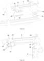
- the device for measuring knee torque during static contraction in bedridden patientsaccording to a possible embodiment as shown in figure 1 comprises the following components:
- the angles between the long 1 and shorter elements 4, 5 of the dynamometer frameworkmay be adjusted according to patient's body measurements. As the longer horizontal element 1 may be rotated with respect to the base plate 2, measurements on both legs are possible as shown in Figure 2 .
- the length and width of the base plate 2are 60 and 30 cm, respectively, with small deviations allowed ( ⁇ 5 cm).
- the long horizontal element 1is approximately 1 m long, while the shorter elements (4, 5) of the dynamometer framework are approximately 0.5 m in length.
- the long horizontal element 1is attached to the base plate 2 with a locking unit, which includes a rotatable mechanism 3 that can be unlocked with a screw to allow rotation of the long horizontal element 1 around the long axis of the base plate 2 to achieve the two opposite configurations shown in Figure 2 .
- the proximal short element 4attaches to the longer horizontal element, and the distal short element 5 attaches to the proximal short element.
- the proximal attachment block 6 between the horizontal long element 1 and the proximal short element 4is movable across the length of the horizontal long element 1. Specifically, the proximal attachment block 6 is inserted on the horizontal longer element 1 in the way that it can slide along it as on the rail. The proximal attachment block is unlocked by releasing the screw 7. The proximal shorter element 4 is attached to the proximal attachment block 6. This junction involves one of the screws and allows the rotation of the proximal shorter element. When the desired position is reached, the screw 8 is tightened to secure the short element in place. The proximal 4 and distal 5 short elements are attached together in the same way, enabling rotation and fixation. The said joints between the elements enable to change the configuration of the device between folded ( Figure 1b ) and unfolded state ( Figure 1a ).
- the fixation frameworkis attached to the base plate and consists of two vertical poles, one 9 on the side of the main dynamometer frame and one on the opposite side 10.
- the vertical polesare connected with the horizontal pole 11.
- the first vertical pole 9is attached to the long horizontal element 1 in the same manner as the proximal short element 4.
- the attachment block for the pole 12is the same as the proximal attachment block 6.
- the second vertical pole 10is not rotatable, but it can be removed from the base plate 2 when needed.
- the position of the second vertical polemay be fixed with a locking pin or a suitably shaped locking mechanism.
- the horizontal pole 11is positioned perpendicularly to the vertical poles 9,10.
- the horizontal pole 11must be padded to prevent discomfort of the patients. Namely, the horizontal pole 11 is pressed against the users hips to ensure the stability of the hip/pelvic area during the measurements.
- On the side of the first vertical pole 9, the horizontal pole 11is attached via a connecting holding element 15.
- the said connecting element 15is directly attached to the horizontal pole 11.
- the vertical pole 9passes through the opening that is cut into the holding element 15 with a locking pin.
- the second vertical pole 10has several intends, intended for securing of the horizontal element 11.
- an additional cylindrical element 16is provided that ensures the stability of the knee joint during the testing.
- An additional aluminium plate 17is attached at the inner side of the proximal short element 4.
- the aluminium plate 17covers the proximal short element 4 in its distal part, starting the junction of the short elements and covering additional 10 cm of the proximal short element 4.
- the cylindrical element 16is attached to the aluminium plate 17.
- the plateis removable and may be mounted also on the opposite side of the junction, which needs to be done when the testing leg is changed.
- the knee belt 18is provided to secure the leg against the cylindrical element 16.
- the shin braceis attached to the distal short element 5.
- the attachment point of the shin braceis movable along the distal short element 5.
- the shin braceconsists of a basic frame 19 and two fixation pads 20.
- the basic frame 19is in contact with the distal short element 5.
- the point attachment between the two structuresmay be changed, by releasing the screwing mechanism 21.
- Within the basic frame 19, two pads 20are positioned.
- the said pads 20are facing each other with their concave sides and are intended to grasp the subject's shin as shown in figure Figure 3a .
- Additional belt 22is provided, which makes possible to tightly fixate the pads 20 against the subject's shin.
- the main electronic unit 23is located at the end of the distal short element. It receives signal input from the torque sensor 24, which is located in the junction between the two short elements 4,5.
- the main electronic unitcomprises:
- Figure 5depicts the typical position of the patient when prepared for performing measurements, wherein the horizontal pole 11 of the fixation frame is placed on the patient's hips, patient's knee and shin are secured with the knee belt and the shin brace and the distal short element 5 of the dynamometer framework is parallel to the long element 1 of the dynamometer framework.
Landscapes
- Health & Medical Sciences (AREA)
- Life Sciences & Earth Sciences (AREA)
- Heart & Thoracic Surgery (AREA)
- Medical Informatics (AREA)
- Physics & Mathematics (AREA)
- Veterinary Medicine (AREA)
- Biophysics (AREA)
- Pathology (AREA)
- Engineering & Computer Science (AREA)
- Biomedical Technology (AREA)
- Public Health (AREA)
- General Health & Medical Sciences (AREA)
- Molecular Biology (AREA)
- Surgery (AREA)
- Animal Behavior & Ethology (AREA)
- Oral & Maxillofacial Surgery (AREA)
- Dentistry (AREA)
- Physical Education & Sports Medicine (AREA)
- Physiology (AREA)
- Orthopedic Medicine & Surgery (AREA)
- Rheumatology (AREA)
- Measurement Of The Respiration, Hearing Ability, Form, And Blood Characteristics Of Living Organisms (AREA)
Description
- The present invention belongs to the field of medical devices, more precisely to the field of devices for measuring muscle function. The object of the invention is a device for measuring knee torque during static contraction in bedridden humans.
- Musculoskeletal system is an anatomical term that refers to an organ system that is formed by muscles and bones. The musculoskeletal system gives humans the possibility to move through space and perform various physical activities, such as walking and running, and to maintain an upright posture. The ability of the human body to move is largely dependent on the level motor abilities, such as muscle strength, postural balance and flexibility. Muscle strength is defined as the maximum amount of force that a muscle can exert against a resistance. Sufficient level of strength is paramount for the human to be able to perform physical activities. In sport, the strength is developed to the highest possible level to maximize the performance of the athlete. In physical therapy and rehabilitation, the strength is typically aimed to be restored (e.g. after an injury) or improved (e.g. to prevent subsequent injuries). Strength is developed with a training that comprises of repetitions of specific activities, typically involving movements against an external resistance. Strengthening of the muscles is possible with the use of elastic resistance (e.g. elastic bands or tubes), exercise machines, based on pneumatic resistance, or by lifting/moving heavy objects, such as weights.
- Direct quantification of muscle strength is impossible in humans. Therefore, the procedures for assessing individual's strength instead measure the torque that the muscles generate around a given joint. For example, the extension torque generated in the knee joint is accepted as a measure of the strength of the muscles that generate forces that are translated to extension torque. Joint torque is typically measured with devices called dynamometers, which are comprised of one or more torque or forces sensors and a mechanical structure that enable appropriate positioning of the person. The dynamometers may enable assessing of static strength (i.e. produced torque while the body is not moving) or dynamic strength (i.e. produced torque while the body is moving). Most often, scientists and clinicians are interested in maximal voluntary torque, which is defined as the torque that is produced by the subject with his/her maximal effort. In some cases, another measure of interest includes the involuntary torque (e.g., evoked by electrical stimulation).
- The knee joint is one of the most commonly assessed joints in terms of strength in sport sciences and medicine, rehabilitation, gerontology and other human health sciences. This is attributable to the convenience of the knee strength measurements, as well as the good validity and reliability. Various devices have been developed to enable knee torque measurements. Most devices are constructed in a way to allow the subject to be seated, such as devices disclosed in documents
US4702108A ,US4727860A andCA2883174A1 . Moreover, some of the devices allow for the measurements in lying (prone or supine) positions. One of the main limitations of the state-of-the-art dynamometers their weight and size, which makes their transport very limited. On the other hand, transportable devices, such as hand-held dynamometers, are not highly reliable. Therefore, valid and reliable strength measurements are not accessible to some populations, notably for the patients who are hospitalized and are unable to get of their beds. - The aim of the present invention is to provide a transportable dynamometer device that enables the measurement of knee joint torque in a lying (supine) position. The design of the dynamometer should allow easy set-up of the patients without them leaving the bed.
- Several devices that allow knee torque measurements in the seated position have been developed and disclosed. The device disclosed in
US4702108A is characterized by complex mechanical frame, which enables knee torque measurements in a seated position whilst the subject is fixated. The position of the leg within the device can be configured, which enables that the knee torque is assessed at different positions (i.e. different angles) of the knee. Another similar device has been disclosed inUS4727860A . This device combines features that enable both exercise and testing, including the assessment of the knee torque, but not in the lying position. Similarly, the device disclosed inCA2883174A1 enables knee torque measurements and is relatively low-cost and easy-to-transport, however, the measurements cannot be performed in a lying position. - Several dynamometers are designed in a way to enable measurements of the strength of more than one joint, such as the ones disclosed in documents
US2590055A ,US4727860A ,US5722937A ,US2006224087 , however, none of these enable measurements to be done in a lying position, let alone, none of these devices can be used with or integrated within a hospital bed. Patent applicationUS2006224087 discloses a complicated construction of a device for measuring knee-torque in a sitting position. Among other components necessary for the stability of the device, the latter has a base plate on which a tested person sits and a dynamometer framework comprising two elements with an intersection at the knee joint. These two elements are pivotably connected and one is arranged to receive and fix the shin of the tested person, while the other element is arranged to be located at the side of the thigh of the tested person. The position of the user is fixed with a belt, however, this is not efficient in preventing movement of the hips, which is crucial for ensuring reliable measurement. - The present invention is functionally similar to the device disclosed in patent
US2590055A . This device enables torque measurements for different joints, and enables the measurements to be performed in different positions, including lying. However, the said device is complex, heavy and non-transportable. - The present invention is based on a large body of scientific works that demonstrate the utility, validity and reliability of devices for measurement of knee joint torque. The main characteristic of the invention is that its construction is arranged for measurements in lying position, which is particularly useful for patients not able to be seated or put in any other position. Reliable measurements of knee strength in bedridden patients are important to evaluate their status or rehabilitation progress, which enables hospital and/or nursing home staff to decide on further treatments and/or rehabilitation.
- The invention is best summarized by the device of
claim 1 and the method ofclaim 13. Advantageous variations are according to dependent claims 2-12, 14, 15. - The device for measuring knee torque during static contraction in bedridden humans will be described in further detail based on exemplary embodiments and figures, which show:
- Figure 1
- The device shown as folded (a) and unfolded (b)
- Figure 2
- The device shown as to be used for the measurement of the right (a and the left (b) leg
- Figure 3
- Close up of the shorter elements, showing how the leg is secured to the device (a), with the elements also depicted without the leg (b)
- Figure 4
- Close up of the electronic unit
- Figure 5
- A representative image of the suggested position for measurements
- The device for measuring knee torque during static contraction in bedridden patients according to a possible embodiment as shown in
figure 1 comprises the following components: - a
base plate 2, which is arranged to be positioned under the patient's hips, - a fixation frame, intended for fixating the device to the patient, comprising:
- two
vertical poles base plate 2; - a horizontal height-
adjustable pole 11 for forming a rectangle together with thebase plate 2 and thevertical poles
- two
- a mechanical dynamometer framework, comprising:
- a long horizontal element attached to any side on one end of the base plate,
- two shorter elements connected in series next to the longer horizontal element opposite from the base plate,
- a
torque sensor 24 installed at the junction of the two shorter elements; - a brace for fixation of the shin, located at the distal part of the second shorter element;
- a
fixation belt 18 for the knee, located at the junction of theshort elements - a
cylindrical element 16 for knee support, located at the junction of theshort elements - main
electronic unit 23 for controlling measurements and thetorque sensor 24 readings. - The angles between the long 1 and
shorter elements horizontal element 1 may be rotated with respect to thebase plate 2, measurements on both legs are possible as shown inFigure 2 . - The length and width of the
base plate 2 are 60 and 30 cm, respectively, with small deviations allowed (< 5 cm). The longhorizontal element 1 is approximately 1 m long, while the shorter elements (4, 5) of the dynamometer framework are approximately 0.5 m in length. The longhorizontal element 1 is attached to thebase plate 2 with a locking unit, which includes arotatable mechanism 3 that can be unlocked with a screw to allow rotation of the longhorizontal element 1 around the long axis of thebase plate 2 to achieve the two opposite configurations shown inFigure 2 . The proximalshort element 4 attaches to the longer horizontal element, and the distalshort element 5 attaches to the proximal short element. Theproximal attachment block 6 between the horizontallong element 1 and the proximalshort element 4 is movable across the length of the horizontallong element 1. Specifically, theproximal attachment block 6 is inserted on the horizontallonger element 1 in the way that it can slide along it as on the rail. The proximal attachment block is unlocked by releasing thescrew 7. The proximalshorter element 4 is attached to theproximal attachment block 6. This junction involves one of the screws and allows the rotation of the proximal shorter element. When the desired position is reached, thescrew 8 is tightened to secure the short element in place. The proximal 4 and distal 5 short elements are attached together in the same way, enabling rotation and fixation. The said joints between the elements enable to change the configuration of the device between folded (Figure 1b ) and unfolded state (Figure 1a ). - The fixation framework is attached to the base plate and consists of two vertical poles, one 9 on the side of the main dynamometer frame and one on the
opposite side 10. The vertical poles are connected with thehorizontal pole 11. The firstvertical pole 9 is attached to the longhorizontal element 1 in the same manner as the proximalshort element 4. The attachment block for thepole 12 is the same as theproximal attachment block 6. On the attachment block for thepole 12, there is an additional supportingelement 13, into which the fistvertical pole 9 is inserted. This enables the pole to be rotated in the transversal plane. This is necessary, similar to the rotation of the long horizontal element, to accommodate the configuration of the device for the measurement of the opposite leg. The secondvertical pole 10 is not rotatable, but it can be removed from thebase plate 2 when needed. The position of the second vertical pole may be fixed with a locking pin or a suitably shaped locking mechanism. Thehorizontal pole 11 is positioned perpendicularly to thevertical poles horizontal pole 11 must be padded to prevent discomfort of the patients. Namely, thehorizontal pole 11 is pressed against the users hips to ensure the stability of the hip/pelvic area during the measurements. On the side of the firstvertical pole 9, thehorizontal pole 11 is attached via a connecting holdingelement 15. The said connectingelement 15 is directly attached to thehorizontal pole 11. Thevertical pole 9 passes through the opening that is cut into the holdingelement 15 with a locking pin. The secondvertical pole 10 has several intends, intended for securing of thehorizontal element 11. - At the junction of the two
short elements cylindrical element 16 is provided that ensures the stability of the knee joint during the testing. Anadditional aluminium plate 17 is attached at the inner side of the proximalshort element 4. Thealuminium plate 17 covers the proximalshort element 4 in its distal part, starting the junction of the short elements and covering additional 10 cm of the proximalshort element 4. Thecylindrical element 16 is attached to thealuminium plate 17. The plate is removable and may be mounted also on the opposite side of the junction, which needs to be done when the testing leg is changed. Theknee belt 18 is provided to secure the leg against thecylindrical element 16. - The shin brace is attached to the distal
short element 5. The attachment point of the shin brace is movable along the distalshort element 5. The shin brace consists of abasic frame 19 and twofixation pads 20. Thebasic frame 19 is in contact with the distalshort element 5. The point attachment between the two structures may be changed, by releasing the screwingmechanism 21. Within thebasic frame 19, twopads 20 are positioned. The saidpads 20 are facing each other with their concave sides and are intended to grasp the subject's shin as shown in figureFigure 3a .Additional belt 22 is provided, which makes possible to tightly fixate thepads 20 against the subject's shin. - As shown in
Figure 4 the mainelectronic unit 23 is located at the end of the distal short element. It receives signal input from thetorque sensor 24, which is located in the junction between the twoshort elements - an on/off
switch 25, - input/
output ports 27 such as a USB port, - a
wireless antenna 26, which enables to transmit the data wirelessly, and - a raw signal out connector (28).
- The device as described above ensures high accuracy measurements of the joint torque, especially in patients constrained to their beds at hospitals or nursing homes, but also elsewhere.
Figure 5 depicts the typical position of the patient when prepared for performing measurements, wherein thehorizontal pole 11 of the fixation frame is placed on the patient's hips, patient's knee and shin are secured with the knee belt and the shin brace and the distalshort element 5 of the dynamometer framework is parallel to thelong element 1 of the dynamometer framework.
Claims (15)
- A device for measuring knee torque during static voluntary or stimulated contraction in bedridden humans, for performing measurements on a knee of a leg of a human placed in supine position, wherein the device comprises:- a base plate (2), which is arranged to be positioned under the patient's hips in the supine position, wherein further elements and their orientation are defined with respect to an orientation of the device in which the base plate is horizontally oriented;- fixation means connected to the base plate (2) for fixation of the device to the patient hips for ensuring reliable measurements;- a mechanical dynamometer framework, comprising:∘ a long element (1) attached at a first end to one side of the base plate (2), such that the long element extends away from the base plate,∘ two shorter elements (4,5) connected to the longer element (1) at the second end of the longer element, , wherein the first shorter element (4) is on one end slidably and rotatably mounted on the longer horizontal element (1) and the second shorter element (5) is rotatably mounted the other end of the first shorter element (4),wherein the long element (1) is arranged to be placed on the outer side of the tested leg;- a torque sensor installed at the junction of the two shorter elements (4,5);- a brace for fixation of the shin, located at the free end of the second shorter element (5);- a fixation belt (18) for the knee, located at the junction of the short elements (4,5);- a cylindrical element (16) for knee support, located at the junction of the short elements (4,5);- a main electronic unit (23) for processing data sent from the torque sensor.
- The device for measuring knee torque during static contraction in bedridden humans according to claim 1, wherein fixation means may be an adjustable belt or preferably a fixation frame, which comprises:- two vertical poles (9,10), one on both sides of the base plate (2);- a horizontal height-adjustable pole (11) for forming a rectangle together with the base plate (2) and the vertical poles (9,10), which is arranged to safely stabilize the patient's hips, wherein one of the vertical poles (9,10) can be reversibly removed and installed for easier positioning of the patient on the device,so that the three poles (9,10,11) form a rectangle parallel to transversal cross-section of the patient's body.
- The device for measuring knee torque during static contraction in bedridden humans according to claim 2, wherein the horizontal pole (11) is preferably equipped with two shorter vertical elements at the sides, said vertical elements being perpendicular to the horizontal pole and parallel to the vertical poles; the shorter vertical elements are slidably mounted in the horizontal pole (11), so that the distance between them can be adjusted; and wherein these shorter vertical elements are provided to fix the patient's hips but at the same time allow needed space in case flexion and extension of the knee have to be stimulated.
- The device for measuring knee torque during static contraction in bedridden humans according to any of the preceding claims,characterized in that angles between the long horizontal element (1) and the proximal shorter element (4) as well as between the two shorter elements (4,5) can be adjusted with suitable mountings.
- The device for measuring knee torque during static contraction in bedridden humans according to any of the preceding claims,characterized in that:- a first mounting is between the long horizontal element (1) and the proximal shorter element (4) is designed as a proximal attachment block (6), which can slide along at least one groove or rail provided in the long horizontal element (1), wherein movement of the said block (6) is controlled with a safety pin or screw (7) arranged to fall into a suitable hole in the long element (1), so that sliding motion of the proximal shorter element (4) is disabled when the pin (7) sits in the said hole; andin that- the proximal attachment block (6) also ensures rotation of the proximal short element (4) from the horizontal position into the vertical position needed for measurements, wherein the angle between the horizontal element (1) and the proximal shorter element (4) may be adjusted by rotating the shorter element (4) and locking its position with a second pin (8) corresponding to a second hole.
- The device for measuring knee torque during static contraction in bedridden humans according to any of the preceding claims,characterized in that the first and second short elements (4,5) are attached in a second mounting, enabling rotation and fixation with pins or screws.
- The device for measuring knee torque during static contraction in bedridden humans according to any of the preceding claims,characterized in that the longer horizontal element (1) is attached to the base plate (2) with a locking unit, which includes a rotatable mechanism that can be unlocked to allow rotation of the long horizontal element (1) around the long axis of the base plate (2).
- The device for measuring knee torque during static contraction in bedridden humans according to any of the preceding claims,characterized in that- the base plate (2) is made of hard, non-compliant material, such as aluminium or other metal materials, wherein the preferred length and width of the base plate (2) are between 50 and 70 cm, optimally 60 cm, and between 25 and 35 cm, optimally 30 cm, respectively; andin that- the long horizontal element (1) is approximately 1 m long and is made of a single aluminium profile, while the shorter elements (4,5) are aluminium profiles measuring 0.5 m in length.
- The device for measuring knee torque during static contraction in bedridden humans according to any of the preceding claims,characterized in that the knee support (16) may be fixed or may be preferably movable using known rotatable mountings so that a suitable knee angle can be set; andin that the knee support (16) is provided with the belt (18) attached near the junction of the two shorter elements (4,5) for securing the knee tightly against the cylindrical support element (16).
- The device for measuring knee torque during static contraction in bedridden humans according to any of the preceding claims,characterized in that the shin brace has two slightly curved surfaces, which are facing each other with their concave sides, wherein the distance between the surfaces is adjustable, which allows for the shin to be grasped at the distal part just above the ankle.
- The device for measuring knee torque during static contraction in bedridden humans according to any of the preceding claims,characterized in that the torque sensor can be any suitable to measure torque, which is arranged to send data to the main electronic unit during measurement, wherein the said main electronic (23) unit comprises:- an on/off switch (25),- input/output ports (27) such as a USB port,- a wireless antenna (26), which enables to transmit the data wirelessly, and- a raw signal out connector (28),and is arranged to amplify signals from the torque sensor, performing analogue-to-digital conversion, acquiring the data at 1000 Hz and transmitting the signals via a Bluetooth module to a computer.
- The device for measuring knee torque during static contraction in bedridden humans according to any of the preceding claims,characterized in that the device may further comprise additional plates connected to the long horizontal element of the dynamometer framework.
- A method for using the device according to any of the preceding claims,characterized in that a patient is positioned and fixated as follows:- the patient's hip/pelvic area is resting on the base plate (2), and the patient is lying supine,- the fixation frame (9,10,11) is tightly securing the patients hips against the base plate,- the longer horizontal element (1) continues horizontally from the end of the base plate (2) on the side of the tested leg,- the two shorter elements (4,5) are arranged in a triangle shape, wherein the first shorter element (4) starts at the distal part of the longer frame element, and points towards the patient's upper body and the junction of the two shorter elements is at the knee joint, while the second shorter element (5) is pointing away from the subject,- the distal part of the shin is secured within the fixation brace,- the knee is secured against the cylindrical element (16) with fixation belt (18),- patient's hip and knee joints are in a flexed position (around 45° each, with possible adjustments).
- A method using the device according to the preceding claim,characterized in that measurements are performed in the following way:- the patient flexes and extends the knee or muscle activity is triggered externally using known methods for stimulation of groin nerve or thigh muscle, wherein the sensor measures the created torque,- flexion and extension may be repeated several times in order to ensure a more reliable measurement,- the data from the sensor are sent to the main electronic unit and optionally a computer for processing and analysis.
- The device according to any of claims 1-12,characterized in that it is embedded into a frame of a bed.
Priority Applications (1)
| Application Number | Priority Date | Filing Date | Title |
|---|---|---|---|
| EP20214543.9AEP3900614B1 (en) | 2020-12-16 | 2020-12-16 | Device for measuring knee torque in bedridden humans and method for using the device |
Applications Claiming Priority (1)
| Application Number | Priority Date | Filing Date | Title |
|---|---|---|---|
| EP20214543.9AEP3900614B1 (en) | 2020-12-16 | 2020-12-16 | Device for measuring knee torque in bedridden humans and method for using the device |
Publications (2)
| Publication Number | Publication Date |
|---|---|
| EP3900614A1 EP3900614A1 (en) | 2021-10-27 |
| EP3900614B1true EP3900614B1 (en) | 2023-04-26 |
Family
ID=73855057
Family Applications (1)
| Application Number | Title | Priority Date | Filing Date |
|---|---|---|---|
| EP20214543.9AActiveEP3900614B1 (en) | 2020-12-16 | 2020-12-16 | Device for measuring knee torque in bedridden humans and method for using the device |
Country Status (1)
| Country | Link |
|---|---|
| EP (1) | EP3900614B1 (en) |
Family Cites Families (10)
| Publication number | Priority date | Publication date | Assignee | Title |
|---|---|---|---|---|
| US2590055A (en) | 1946-06-28 | 1952-03-18 | Timmerman Johannes | Apparatus for measuring muscular strength |
| US4702108A (en) | 1985-06-24 | 1987-10-27 | Regents Of The Univ. Of Minnesota | Method and apparatus for measuring the isometric muscle strength of multiple muscle groups in the human body |
| US4727860A (en) | 1986-06-06 | 1988-03-01 | Isotechnologies, Inc. | Exercise apparatus for the knee |
| WO1995026701A1 (en) | 1994-03-30 | 1995-10-12 | Lumex, Inc. | Exercise method and apparatus with cycloidal reducer |
| US6149550A (en) | 1999-09-30 | 2000-11-21 | Shteingold; David | Muscle strength testing apparatus |
| AU2003902868A0 (en)* | 2003-06-06 | 2003-06-26 | The University Of Queensland | Muscle assessment |
| US7412904B2 (en)* | 2005-04-05 | 2008-08-19 | Holder Thomas L | Isokinetic testing apparatus and system |
| US7493812B2 (en)* | 2007-03-07 | 2009-02-24 | The General Hospital Corporation | Isometric strength testing apparatus |
| RU2626872C2 (en) | 2012-09-03 | 2017-08-02 | Квинсленд Юниверсити Оф Текнолоджи | Device and method for knee flexor evaluation |
| CN109746940A (en)* | 2019-01-14 | 2019-05-14 | 电子科技大学 | A device for testing single-degree-of-freedom joint torque |
- 2020
- 2020-12-16EPEP20214543.9Apatent/EP3900614B1/enactiveActive
Also Published As
| Publication number | Publication date |
|---|---|
| EP3900614A1 (en) | 2021-10-27 |
Similar Documents
| Publication | Publication Date | Title |
|---|---|---|
| EP2892430B2 (en) | Apparatus and method for knee flexor assessment | |
| Pua et al. | Intrarater test-retest reliability of hip range of motion and hip muscle strength measurements in persons with hip osteoarthritis | |
| Abdoli-E et al. | An on-body personal lift augmentation device (PLAD) reduces EMG amplitude of erector spinae during lifting tasks | |
| Katoh et al. | Test-retest reliability of isometric leg muscle strength measurements made using a hand-held dynamometer restrained by a belt: comparisons during and between sessions | |
| CN101820845B (en) | Robot training system with multi-directional modules | |
| Li et al. | The development, validity, and reliability of a manual muscle testing device with integrated limb position sensors | |
| US20160271443A1 (en) | Leg stretcher | |
| Roebroeck et al. | Reliability assessment of isometric knee extension measurements with a computer-assisted hand-held dynamometer | |
| CA2624736A1 (en) | Isometric strength testing apparatus | |
| US20200275893A1 (en) | Apparatus for the analysis and measurement of maximum and expolsive strength of lower extremity muscles | |
| CA2857693C (en) | Limb strength measurement device | |
| AU2009250967A1 (en) | Comparing human muscle strength on opposite sides | |
| Maayah et al. | Test-retest strength reliability of the Electronic Push/Pull Dynamometer (EPPD) in the measurement of the quadriceps and hamstring muscles on a new chair | |
| EP3900614B1 (en) | Device for measuring knee torque in bedridden humans and method for using the device | |
| CN207101284U (en) | A kind of servicing unit of joint of vertebral column Weight carrying position medical imaging | |
| Seeds et al. | Abnormal patient data for the Isostation B100 | |
| Ammar | Inter-rater and test-retest reliability of hand held dynamometer in shoulder dysfunction | |
| CN113749612A (en) | Ankle joint evaluation device, ankle joint evaluation apparatus, ankle joint evaluation system, ankle joint evaluation method, and storage medium | |
| JP5594725B2 (en) | Simple muscle strength measuring instrument | |
| Landry et al. | A wearable sensor system for quantifying isometric elbow and knee joint strength | |
| RU2537783C2 (en) | Device for measurement of kinetic and force parameters of hand | |
| Phillips | Measuring flexibility | |
| RU2270649C2 (en) | Stationary vibration-decompression assembly | |
| Saadprai et al. | DESIGN AND DEVELOPMENT OF A CORE STRENGTHENING EXERCISE AND REHABILITATION MACHINE FOR ELDERLY. | |
| LT6949B (en) | Upper and lower limb isometric force measurement and training device |
Legal Events
| Date | Code | Title | Description |
|---|---|---|---|
| PUAI | Public reference made under article 153(3) epc to a published international application that has entered the european phase | Free format text:ORIGINAL CODE: 0009012 | |
| STAA | Information on the status of an ep patent application or granted ep patent | Free format text:STATUS: THE APPLICATION HAS BEEN PUBLISHED | |
| AK | Designated contracting states | Kind code of ref document:A1 Designated state(s):AL AT BE BG CH CY CZ DE DK EE ES FI FR GB GR HR HU IE IS IT LI LT LU LV MC MK MT NL NO PL PT RO RS SE SI SK SM TR | |
| B565 | Issuance of search results under rule 164(2) epc | Effective date:20210617 | |
| STAA | Information on the status of an ep patent application or granted ep patent | Free format text:STATUS: REQUEST FOR EXAMINATION WAS MADE | |
| 17P | Request for examination filed | Effective date:20220128 | |
| RBV | Designated contracting states (corrected) | Designated state(s):AL AT BE BG CH CY CZ DE DK EE ES FI FR GB GR HR HU IE IS IT LI LT LU LV MC MK MT NL NO PL PT RO RS SE SI SK SM TR | |
| STAA | Information on the status of an ep patent application or granted ep patent | Free format text:STATUS: EXAMINATION IS IN PROGRESS | |
| 17Q | First examination report despatched | Effective date:20220413 | |
| GRAP | Despatch of communication of intention to grant a patent | Free format text:ORIGINAL CODE: EPIDOSNIGR1 | |
| STAA | Information on the status of an ep patent application or granted ep patent | Free format text:STATUS: GRANT OF PATENT IS INTENDED | |
| INTG | Intention to grant announced | Effective date:20230103 | |
| GRAS | Grant fee paid | Free format text:ORIGINAL CODE: EPIDOSNIGR3 | |
| GRAA | (expected) grant | Free format text:ORIGINAL CODE: 0009210 | |
| STAA | Information on the status of an ep patent application or granted ep patent | Free format text:STATUS: THE PATENT HAS BEEN GRANTED | |
| AK | Designated contracting states | Kind code of ref document:B1 Designated state(s):AL AT BE BG CH CY CZ DE DK EE ES FI FR GB GR HR HU IE IS IT LI LT LU LV MC MK MT NL NO PL PT RO RS SE SI SK SM TR | |
| REG | Reference to a national code | Ref country code:GB Ref legal event code:FG4D | |
| REG | Reference to a national code | Ref country code:CH Ref legal event code:EP | |
| REG | Reference to a national code | Ref country code:DE Ref legal event code:R096 Ref document number:602020010095 Country of ref document:DE | |
| REG | Reference to a national code | Ref country code:AT Ref legal event code:REF Ref document number:1562259 Country of ref document:AT Kind code of ref document:T Effective date:20230515 | |
| REG | Reference to a national code | Ref country code:IE Ref legal event code:FG4D | |
| REG | Reference to a national code | Ref country code:LT Ref legal event code:MG9D | |
| REG | Reference to a national code | Ref country code:NL Ref legal event code:MP Effective date:20230426 | |
| REG | Reference to a national code | Ref country code:AT Ref legal event code:MK05 Ref document number:1562259 Country of ref document:AT Kind code of ref document:T Effective date:20230426 | |
| PG25 | Lapsed in a contracting state [announced via postgrant information from national office to epo] | Ref country code:NL Free format text:LAPSE BECAUSE OF FAILURE TO SUBMIT A TRANSLATION OF THE DESCRIPTION OR TO PAY THE FEE WITHIN THE PRESCRIBED TIME-LIMIT Effective date:20230426 | |
| PG25 | Lapsed in a contracting state [announced via postgrant information from national office to epo] | Ref country code:SE Free format text:LAPSE BECAUSE OF FAILURE TO SUBMIT A TRANSLATION OF THE DESCRIPTION OR TO PAY THE FEE WITHIN THE PRESCRIBED TIME-LIMIT Effective date:20230426 Ref country code:PT Free format text:LAPSE BECAUSE OF FAILURE TO SUBMIT A TRANSLATION OF THE DESCRIPTION OR TO PAY THE FEE WITHIN THE PRESCRIBED TIME-LIMIT Effective date:20230828 Ref country code:NO Free format text:LAPSE BECAUSE OF FAILURE TO SUBMIT A TRANSLATION OF THE DESCRIPTION OR TO PAY THE FEE WITHIN THE PRESCRIBED TIME-LIMIT Effective date:20230726 Ref country code:ES Free format text:LAPSE BECAUSE OF FAILURE TO SUBMIT A TRANSLATION OF THE DESCRIPTION OR TO PAY THE FEE WITHIN THE PRESCRIBED TIME-LIMIT Effective date:20230426 Ref country code:AT Free format text:LAPSE BECAUSE OF FAILURE TO SUBMIT A TRANSLATION OF THE DESCRIPTION OR TO PAY THE FEE WITHIN THE PRESCRIBED TIME-LIMIT Effective date:20230426 | |
| PG25 | Lapsed in a contracting state [announced via postgrant information from national office to epo] | Ref country code:RS Free format text:LAPSE BECAUSE OF FAILURE TO SUBMIT A TRANSLATION OF THE DESCRIPTION OR TO PAY THE FEE WITHIN THE PRESCRIBED TIME-LIMIT Effective date:20230426 Ref country code:PL Free format text:LAPSE BECAUSE OF FAILURE TO SUBMIT A TRANSLATION OF THE DESCRIPTION OR TO PAY THE FEE WITHIN THE PRESCRIBED TIME-LIMIT Effective date:20230426 Ref country code:LV Free format text:LAPSE BECAUSE OF FAILURE TO SUBMIT A TRANSLATION OF THE DESCRIPTION OR TO PAY THE FEE WITHIN THE PRESCRIBED TIME-LIMIT Effective date:20230426 Ref country code:LT Free format text:LAPSE BECAUSE OF FAILURE TO SUBMIT A TRANSLATION OF THE DESCRIPTION OR TO PAY THE FEE WITHIN THE PRESCRIBED TIME-LIMIT Effective date:20230426 Ref country code:IS Free format text:LAPSE BECAUSE OF FAILURE TO SUBMIT A TRANSLATION OF THE DESCRIPTION OR TO PAY THE FEE WITHIN THE PRESCRIBED TIME-LIMIT Effective date:20230826 Ref country code:HR Free format text:LAPSE BECAUSE OF FAILURE TO SUBMIT A TRANSLATION OF THE DESCRIPTION OR TO PAY THE FEE WITHIN THE PRESCRIBED TIME-LIMIT Effective date:20230426 Ref country code:GR Free format text:LAPSE BECAUSE OF FAILURE TO SUBMIT A TRANSLATION OF THE DESCRIPTION OR TO PAY THE FEE WITHIN THE PRESCRIBED TIME-LIMIT Effective date:20230727 | |
| PG25 | Lapsed in a contracting state [announced via postgrant information from national office to epo] | Ref country code:FI Free format text:LAPSE BECAUSE OF FAILURE TO SUBMIT A TRANSLATION OF THE DESCRIPTION OR TO PAY THE FEE WITHIN THE PRESCRIBED TIME-LIMIT Effective date:20230426 | |
| PG25 | Lapsed in a contracting state [announced via postgrant information from national office to epo] | Ref country code:SK Free format text:LAPSE BECAUSE OF FAILURE TO SUBMIT A TRANSLATION OF THE DESCRIPTION OR TO PAY THE FEE WITHIN THE PRESCRIBED TIME-LIMIT Effective date:20230426 | |
| REG | Reference to a national code | Ref country code:DE Ref legal event code:R097 Ref document number:602020010095 Country of ref document:DE | |
| PG25 | Lapsed in a contracting state [announced via postgrant information from national office to epo] | Ref country code:SM Free format text:LAPSE BECAUSE OF FAILURE TO SUBMIT A TRANSLATION OF THE DESCRIPTION OR TO PAY THE FEE WITHIN THE PRESCRIBED TIME-LIMIT Effective date:20230426 Ref country code:SK Free format text:LAPSE BECAUSE OF FAILURE TO SUBMIT A TRANSLATION OF THE DESCRIPTION OR TO PAY THE FEE WITHIN THE PRESCRIBED TIME-LIMIT Effective date:20230426 Ref country code:RO Free format text:LAPSE BECAUSE OF FAILURE TO SUBMIT A TRANSLATION OF THE DESCRIPTION OR TO PAY THE FEE WITHIN THE PRESCRIBED TIME-LIMIT Effective date:20230426 Ref country code:EE Free format text:LAPSE BECAUSE OF FAILURE TO SUBMIT A TRANSLATION OF THE DESCRIPTION OR TO PAY THE FEE WITHIN THE PRESCRIBED TIME-LIMIT Effective date:20230426 Ref country code:DK Free format text:LAPSE BECAUSE OF FAILURE TO SUBMIT A TRANSLATION OF THE DESCRIPTION OR TO PAY THE FEE WITHIN THE PRESCRIBED TIME-LIMIT Effective date:20230426 Ref country code:CZ Free format text:LAPSE BECAUSE OF FAILURE TO SUBMIT A TRANSLATION OF THE DESCRIPTION OR TO PAY THE FEE WITHIN THE PRESCRIBED TIME-LIMIT Effective date:20230426 | |
| PLBE | No opposition filed within time limit | Free format text:ORIGINAL CODE: 0009261 | |
| STAA | Information on the status of an ep patent application or granted ep patent | Free format text:STATUS: NO OPPOSITION FILED WITHIN TIME LIMIT | |
| 26N | No opposition filed | Effective date:20240129 | |
| PG25 | Lapsed in a contracting state [announced via postgrant information from national office to epo] | Ref country code:SI Free format text:LAPSE BECAUSE OF FAILURE TO SUBMIT A TRANSLATION OF THE DESCRIPTION OR TO PAY THE FEE WITHIN THE PRESCRIBED TIME-LIMIT Effective date:20230426 | |
| PG25 | Lapsed in a contracting state [announced via postgrant information from national office to epo] | Ref country code:SI Free format text:LAPSE BECAUSE OF FAILURE TO SUBMIT A TRANSLATION OF THE DESCRIPTION OR TO PAY THE FEE WITHIN THE PRESCRIBED TIME-LIMIT Effective date:20230426 Ref country code:IT Free format text:LAPSE BECAUSE OF FAILURE TO SUBMIT A TRANSLATION OF THE DESCRIPTION OR TO PAY THE FEE WITHIN THE PRESCRIBED TIME-LIMIT Effective date:20230426 | |
| REG | Reference to a national code | Ref country code:CH Ref legal event code:PL | |
| PG25 | Lapsed in a contracting state [announced via postgrant information from national office to epo] | Ref country code:LU Free format text:LAPSE BECAUSE OF NON-PAYMENT OF DUE FEES Effective date:20231216 | |
| PG25 | Lapsed in a contracting state [announced via postgrant information from national office to epo] | Ref country code:MC Free format text:LAPSE BECAUSE OF FAILURE TO SUBMIT A TRANSLATION OF THE DESCRIPTION OR TO PAY THE FEE WITHIN THE PRESCRIBED TIME-LIMIT Effective date:20230426 | |
| REG | Reference to a national code | Ref country code:BE Ref legal event code:MM Effective date:20231231 | |
| PG25 | Lapsed in a contracting state [announced via postgrant information from national office to epo] | Ref country code:MC Free format text:LAPSE BECAUSE OF FAILURE TO SUBMIT A TRANSLATION OF THE DESCRIPTION OR TO PAY THE FEE WITHIN THE PRESCRIBED TIME-LIMIT Effective date:20230426 Ref country code:LU Free format text:LAPSE BECAUSE OF NON-PAYMENT OF DUE FEES Effective date:20231216 | |
| REG | Reference to a national code | Ref country code:IE Ref legal event code:MM4A | |
| PG25 | Lapsed in a contracting state [announced via postgrant information from national office to epo] | Ref country code:IE Free format text:LAPSE BECAUSE OF NON-PAYMENT OF DUE FEES Effective date:20231216 | |
| PG25 | Lapsed in a contracting state [announced via postgrant information from national office to epo] | Ref country code:BE Free format text:LAPSE BECAUSE OF NON-PAYMENT OF DUE FEES Effective date:20231231 | |
| PG25 | Lapsed in a contracting state [announced via postgrant information from national office to epo] | Ref country code:FR Free format text:LAPSE BECAUSE OF NON-PAYMENT OF DUE FEES Effective date:20231231 | |
| PG25 | Lapsed in a contracting state [announced via postgrant information from national office to epo] | Ref country code:CH Free format text:LAPSE BECAUSE OF NON-PAYMENT OF DUE FEES Effective date:20231231 | |
| PG25 | Lapsed in a contracting state [announced via postgrant information from national office to epo] | Ref country code:IE Free format text:LAPSE BECAUSE OF NON-PAYMENT OF DUE FEES Effective date:20231216 Ref country code:FR Free format text:LAPSE BECAUSE OF NON-PAYMENT OF DUE FEES Effective date:20231231 Ref country code:CH Free format text:LAPSE BECAUSE OF NON-PAYMENT OF DUE FEES Effective date:20231231 Ref country code:BE Free format text:LAPSE BECAUSE OF NON-PAYMENT OF DUE FEES Effective date:20231231 | |
| PG25 | Lapsed in a contracting state [announced via postgrant information from national office to epo] | Ref country code:BG Free format text:LAPSE BECAUSE OF FAILURE TO SUBMIT A TRANSLATION OF THE DESCRIPTION OR TO PAY THE FEE WITHIN THE PRESCRIBED TIME-LIMIT Effective date:20230426 | |
| PG25 | Lapsed in a contracting state [announced via postgrant information from national office to epo] | Ref country code:BG Free format text:LAPSE BECAUSE OF FAILURE TO SUBMIT A TRANSLATION OF THE DESCRIPTION OR TO PAY THE FEE WITHIN THE PRESCRIBED TIME-LIMIT Effective date:20230426 | |
| PGFP | Annual fee paid to national office [announced via postgrant information from national office to epo] | Ref country code:DE Payment date:20241223 Year of fee payment:5 | |
| PG25 | Lapsed in a contracting state [announced via postgrant information from national office to epo] | Ref country code:CY Free format text:LAPSE BECAUSE OF FAILURE TO SUBMIT A TRANSLATION OF THE DESCRIPTION OR TO PAY THE FEE WITHIN THE PRESCRIBED TIME-LIMIT; INVALID AB INITIO Effective date:20201216 | |
| PG25 | Lapsed in a contracting state [announced via postgrant information from national office to epo] | Ref country code:HU Free format text:LAPSE BECAUSE OF FAILURE TO SUBMIT A TRANSLATION OF THE DESCRIPTION OR TO PAY THE FEE WITHIN THE PRESCRIBED TIME-LIMIT; INVALID AB INITIO Effective date:20201216 | |
| GBPC | Gb: european patent ceased through non-payment of renewal fee | Effective date:20241216 |