EP3900554B1 - Method of operating an aerosol-generating device - Google Patents
Method of operating an aerosol-generating deviceDownload PDFInfo
- Publication number
- EP3900554B1 EP3900554B1EP20171187.6AEP20171187AEP3900554B1EP 3900554 B1EP3900554 B1EP 3900554B1EP 20171187 AEP20171187 AEP 20171187AEP 3900554 B1EP3900554 B1EP 3900554B1
- Authority
- EP
- European Patent Office
- Prior art keywords
- user
- orientation
- mode
- usage
- threshold
- Prior art date
- Legal status (The legal status is an assumption and is not a legal conclusion. Google has not performed a legal analysis and makes no representation as to the accuracy of the status listed.)
- Active
Links
Images


Classifications
- A—HUMAN NECESSITIES
- A24—TOBACCO; CIGARS; CIGARETTES; SIMULATED SMOKING DEVICES; SMOKERS' REQUISITES
- A24F—SMOKERS' REQUISITES; MATCH BOXES; SIMULATED SMOKING DEVICES
- A24F40/00—Electrically operated smoking devices; Component parts thereof; Manufacture thereof; Maintenance or testing thereof; Charging means specially adapted therefor
- A24F40/50—Control or monitoring
- A24F40/53—Monitoring, e.g. fault detection
- A—HUMAN NECESSITIES
- A24—TOBACCO; CIGARS; CIGARETTES; SIMULATED SMOKING DEVICES; SMOKERS' REQUISITES
- A24F—SMOKERS' REQUISITES; MATCH BOXES; SIMULATED SMOKING DEVICES
- A24F40/00—Electrically operated smoking devices; Component parts thereof; Manufacture thereof; Maintenance or testing thereof; Charging means specially adapted therefor
- A24F40/50—Control or monitoring
- A24F40/51—Arrangement of sensors
- A—HUMAN NECESSITIES
- A24—TOBACCO; CIGARS; CIGARETTES; SIMULATED SMOKING DEVICES; SMOKERS' REQUISITES
- A24F—SMOKERS' REQUISITES; MATCH BOXES; SIMULATED SMOKING DEVICES
- A24F40/00—Electrically operated smoking devices; Component parts thereof; Manufacture thereof; Maintenance or testing thereof; Charging means specially adapted therefor
- A24F40/60—Devices with integrated user interfaces
Definitions
- the e-cig 100 facing up or downmay also be defined with respect to any visual pattern, such as a logo or a surface design, to act as a reference for the user. Activation button and LED may not be necessary to provide such reference. In any case, sensors on the device may not be reliant on these physical or visual elements.
Landscapes
- Engineering & Computer Science (AREA)
- Human Computer Interaction (AREA)
- User Interface Of Digital Computer (AREA)
- Containers And Packaging Bodies Having A Special Means To Remove Contents (AREA)
Description
- The present invention relates to a method of operating an aerosol generating device for enhanced user experience. More specifically, it relates to an aerosol generating device such as e-cigarettes, heat-not-burn devices, and the like which is capable of indicating aerosol intake to a user based on the position of the device.
- Inhalers or aerosol generating devices such as e-cigarettes or vaping devices are becoming increasingly popular. They generally heat or warm an aerosolisable substance to generate an aerosol for inhalation, as opposed to burning tobacco as in conventional tobacco products. The generated aerosol may contain a flavour and/or a stimulant (e.g., nicotine or other active component). Users of such inhalers may wish to monitor the amount of flavour or stimulant taken during use at times.
- Most aerosol generating devices incorporate some form of electronic control circuit, typically including a simple computer processor, allowing a user to control operation of the aerosol generation device. However, these devices can be quite restrictive in their settings and may not offer much flexibility to the user. Even in devices that allow a user to customise settings, it requires some effort from the user and may not be intuitive.
WO 2017/137512 A1 discloses an aerosol-generating device with a control system that may be configured to indicate to a user a counted number of detected puffs and to detect a user puff when the liquid aerosol-forming substrate held in the liquid storage portion is substantially perpendicular to the first and second electrodes, such as when the liquid storage portion is determined to be upright.- Therefore, there exists a need for a device that can be operated and controlled in accordance with the user's preference for aerosol monitoring without requiring much effort.
- According to an aspect of the present invention, there is provided a method of operating an aerosol-generating device comprising determining a positional orientation of the device when in use; monitoring usage of the device; activating a first mode of operation when the device is determined to be in a first orientation, wherein in the first mode providing a first indication to a user when the usage of the device reaches a first threshold; and activating a second mode of operation when the device is determined to be in a second orientation, wherein in the second mode providing no indication to the user.
- Advantageously, the user can choose to operate in two different modes by simply flipping the vaping device in a different orientation. It is possible to monitor the vaping usage in both modes but the user is provided an indication on reaching a usage threshold when operating in the first mode. In this way the user can have more control over his or her vaping habits.
- Preferably, the first indication is provided only when the usage of the device in the first orientation reaches the first threshold.
- Preferably, in the said method, the first mode is retained if the device is determined to be in the second orientation for less than a preset period of time and is returned to the first orientation within the preset period.
- Preferably, the first mode is retained if the usage of the device, when in the second orientation, is less than a preset number of puffs before the device is returned to the first orientation.
- Preferably, in the said method, it is determined whether the device is in the first orientation at least once during a predetermined period of use and if so, a second indication is provided to the user at the end of the predetermined period of use.
- Preferably, the second indication is provided to the user when the usage of the device during the predetermined period of use reaches a second threshold.
- Preferably, in the said method, an aerosol source is identified to automatically set the second threshold based on the aerosol source.
- Preferably, in the said method, an input is received from the user to set the second threshold.
- Preferably, in the said method, the second indication is provided to the user when the usage of the device reaches the second threshold after the predetermined period of use irrespective of active mode of operation.
- Preferably, in the said method, a number of puffs is counted to determine the usage of the device, wherein each puff is associated with a time stamp to analyse the usage over time.
- Preferably, the said method further includes receiving an input from the user setting a number of puffs in a session as the first threshold for the first mode and if during the session the setting is changed by the user then resetting the puff count to zero.
- Preferably, in the said method, the difference between the first orientation and the second orientation is 180 degrees along the longitudinal axis of the device.
- According to another aspect of the invention, there is provided an aerosol-generating device comprising a body having an inlet and an outlet with an air channel defined between the inlet and the outlet; an orientation sensor configured to detect a positional orientation of the device when in use; a controller configured to: monitor usage of the device; activate a first mode of operation when the device is detected to be in a first orientation, wherein in the first mode an indication is provided to a user when the usage of the device reaches a first threshold; and activate a second mode of operation when the device is detected to be in a second orientation, wherein in the second mode no indication is provided to the user.
- Embodiments of the invention are now described, by way of example, with reference to the drawings, in which:
Fig. 1 shows an aerosol generating device according to an aspect of the invention;Fig. 2 shows a block diagram of various components of the device ofFig. 1 ;Fig. 3 shows a flow diagram of a method of operating the device ofFig. 1 ; andFigs. 4 and5 show graphs illustrating a control operation of the device ofFig. 1 .Fig. 6 shows a vaping profile of a user displayed on a personal computing device linked with the aerosol generating device ofFig. 1 .- Next, various aspects of the invention will be described. Note that the same or similar portions are denoted with the same or similar reference signs in the descriptions of the drawings below. Note that the drawings are schematic and a ratio of each size is different from a real one. Therefore, specific sizes and the like should be judged in consideration of the following descriptions.
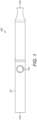
Fig. 1 shows a non-combustion-type aerosol generatingdevice 100, which is a device for inhaling an aerosol by heating or vaporisation without combustion. Thedevice 100 has a rod-like shape with amain body 101 extending from anon-mouthpiece end 102 to amouthpiece end 103. An air channel or path is defined in themain body 100 between theopposite ends generating device 100 in the present example is an electronic cigarette or a vaping device, and is referred to ase-cig 100 hereinafter. Thee-cig 100 works by vaporizing or heating an aerosol source inserted into thee-cig 100 to release a flavour and/or a stimulant for a user to inhale through themouthpiece end 103. The construction and operation of such a device to generate aerosol is well-known in the art and it will be understood by a skilled person that the invention disclosed herein can be applicable to aerosol generation devices in any shapes, configured with any aerosol generating techniques, not limited to the example.- The
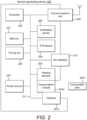
e-cig 100 may include anactivation switch 104 that may be configured to perform at least one of a turn-on and a turn-off of a power source of thee-cig 100. Theactivation switch 104 may be a push button or a touch button disposed at any convenient location on the surface of themain body 101 of thee-cig 100. Alternatively, thee-cig 100 does not rely on a switch button to activate power supply to heater, but rely on a puff sensor to detect air flow and trigger the device to start generating aerosol. Fig. 2 is a block diagram showing various components or modules of thee-cig 100. In one example, thee-cig 100 comprises aconsumables module 201a and aheating element 202 that vaporizes aconsumable item 201b received by theconsumables module 201a to release aerosol containing the flavour and/or stimulant for the user to inhale. In the present example, theconsumable item 201b is a substance containing nicotine. Presence of theconsumable item 201b in theconsumables module 201a may be detected by adetector 201c. Theconsumable item 201b may be in the form of solid or liquid and is heated by theheating element 202 to release the aerosol without combustion. In case theconsumable item 201b is a liquid store, more than one consumable items can be received at theconsumable module 201a. Theheating element 202 may be powered by apower source 203.- The
power source 203 is, for example, a lithium ion battery. Thepower source 203 supplies an electric power necessary for an action of thee-cig 100. For example, thepower source 203 supplies the electric power to all other components or modules included in thee-cig 100. - For the purposes of the present description, it will be understood that the terms vapour and aerosol are interchangeable. In some examples, the heating element is arranged within a capsule or cigarette-like aerosol generating material and connectable to the aerosol generation device, rather than being a component of the aerosol generation device itself.
- In one embodiment, a flavouring is present in the
consumable item 201b. The flavouring may include Ethylvanillin (vanilla), menthol, Isoamyl acetate (banana oil) or similar. In another embodiment, theconsumable item 201b may include an additional flavour source (not shown) provided on the side of themouthpiece end 103 beyond theconsumables module 201a theconsumable item 201b, and generates a flavour to be inhaled by the user together with the aerosol generated from theconsumable item 201b. In yet another embodiment, thee-cig 100 comprises more than one consumable item each comprising a flavouring and/or a certain level of active component (nicotine). In this case, each consumable item can be independently heated to generate aerosol. - The e-cig 100 also includes a
controller 204 that is configured to control various components in the e-cig. For example, thecontroller 204 may control a timing unit 205 (comprising a timer), acommunications unit 206, amemory 207, anorientation sensor 208, and apuff sensor 209 included in thee-cig 100. Thetiming unit 205 is configured to provide time information (e.g., time of the day) and generate timestamp for puff data or event data, which is helpful to analyse user's vaping preference. Thetiming unit 205 is further configured to monitor timing of each puff and breaks in between and provide this information to thecontroller 204 to monitor and potentially restrict the user's usage of thee-cig 100. For example, thetiming unit 205 may determine when to indicate the user on reaching a puff threshold. It is to be noted that the functions of thetiming unit 205 can be consolidated into thecontroller 204. - The
communications unit 206 is configured to manage communication with any personal computing device, a server, a tracking device, or other e-cigs in the vicinity of thee-cig 100. Thememory 207 is configured to store vaping usage history and information such as user settings and preferences. - The e-cig 100 may also include various sensors such as the
orientation sensor 208 and thepuff sensor 209. Theorientation sensor 208, such as a gyroscope, is configured to determine a positional orientation of the e-cig 100, for example, determining if thee-cig 100 is held face up or face down when in use. When thee-cig 100 is used with front face up (such that theactivation button 104 and/or an LED and/or a logo is facing upwards), a first mode of operation is activated in which the user is provided an indication on reaching a puff threshold. This mode is also referred to as the session mode. - When the e-cig is used with front face down (such that the
activation button 104 and/or an LED is facing downwards), a second mode of operation is activated in which the user is provided with no indication on reaching the puff threshold. This mode is also referred to as the free mode. In other words, thee-cig 100 is rotated or turned by 180 degrees along its longitudinal axis to switch between the session mode and the free mode. In the session mode, with the LED facing upwards, the user is indicated of the puff threshold by the means of the LED which is easily visible to the user. In the free mode, with the LED facing downwards, the puff threshold is not indicated to the user. - It is to be noted that the e-cig 100 facing up or down may also be defined with respect to any visual pattern, such as a logo or a surface design, to act as a reference for the user. Activation button and LED may not be necessary to provide such reference. In any case, sensors on the device may not be reliant on these physical or visual elements.
- The
puff sensor 209 is configured to determine the number of puff actions of inhaling the aerosol. Thepuff sensor 209 can also determine a time period required for one puff action of inhaling the aerosol. The recorded usage data can comprise puff duration (i.e., length of a puff), a puff interval (i.e., the time between consecutive puffs), and a fluid and/or nicotine consumption amount. - The e-cig 100 may also include a consumable recognition sensor (now shown) configured to identify the
consumable item 201b inserted in thee-cig 100. The recognition sensor may be included in theconsumables module 201a or thedetector 201c. The recognition sensor may use NFC, RFID or any other known technique to recognise the strength of the stimulant contained in theconsumable item 201b from an NFC/RFID tag disposed on the consumable 201b. - The e-cig 100 may also include an Input-Output (I/O) or
user interface 210 configured to provide indications to the user and to receive inputs from the user. The I/O interface 210 preferably comprises an indication device and an input device. The indication device may comprise a visual light emitting element including one or more Light Emitting Diodes (LEDs), a screen display, or a sound emitter, or other appropriate means to provide indication to users. The visual light-emitting element such as an LED may be disposed at the tip of thenon-mouthpiece end 102, or on a side surface of thee-cig 100. Such an LED may exhibit various light-emitting mode to provide to user within indication of a puff state where the aerosol is being inhaled, a non-puff state where the aerosol is not being inhaled, a pre-heating state when the heater is heating up, a ready-to vape state when the heater operates at target temperature to generate aerosol, a depletion state where LED bar shows depletion level of the aerosol source, and any other information related to the operation status of the e-cig. The input device can be one or more user operable buttons or sensible touch panel, responsible to depression, toggling, or touch. - All the elements described above transmit and/or receive command and/or data via
communication bus 211. - In one embodiment, the
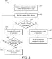
e-cig 100 is also configured to communicate with a personal computing device (now shown) owned by the user. The personal computing device may be a smartphone, tablet, or, a laptop. For the sake of simplicity, the personal computing device is referred to as smartphone hereinafter. Preferably, thee-cig 100 is configured to communicably connect or pair with the smartphone wirelessly using Wi-Fi, Bluetooth, or other wireless communication standards. The smartphone preferably runs a mobile application (commonly referred to as App) that allows the user to interact with the e-cig 100 through a user-friendly interface. The App may be hosted by the manufacturer of thee-cig 100 and compatible with different mobile platforms such as iOS™ and Android™. Fig. 3 shows a flow diagram for aprocess 300 of operating thee-cig 100. It is to be noted that steps in theprocess 300 may not necessarily be performed in the same sequence. Also, not all steps are shown and some of the steps may be optional and can be omitted.- At
step 301, a positional orientation of the device is determined when in use. In the present example, when the user starts to use thee-cig 100, theorientation sensor 208 in thee-cig 100 determines if thee-cig 100 is held in a position facing up or facing down. Optionally, theorientation sensor 208 may be activated when the user pushes theactivation switch 104. In addition, there may be a motion sensor which detects a movement of the e-cig 100 in addition to the activation of theactivation switch 104. Signals from theorientation sensor 208, theactivation switch 104, and the motion sensor may all be processed by thecontroller 204 to determine if one of the two modes of operation is to be activated. - At
step 302, usage of the device is monitored. In the present example, when it is determined that the device is in use, irrespective of the orientation, thecontroller 204 starts monitoring the usage of the e-cig 100 with the aid of thepuff sensor 209 and thetiming unit 205. Thepuff sensor 209 detects each puff inhaled by the user and thetiming unit 205 time stamps each puff as well as monitors the start and end of each puff. In the session mode, thetiming unit 205 starts and stops a timer between two consecutive puffs and monitors a break in a puff session. This is explained later in detail with reference toFigs. 4 and5 . Nonetheless, in both the session mode and the free mode, the number of puffs inhaled by the user is counted and recorded to analyse the user's vaping pattern over time. - At
step 303, it is determined if the device is in a first orientation. In the present example, if thecontroller 204 determines from the signal received from theorientation session 208 that thee-cig 100 is being held facing up, the process moves to step 304 or else it moves to step 307. - At
step 304, a first mode of operation is activated. In the present example, upon determining that thee-cig 100 is held in a position facing up, thecontroller 204 activates the session mode of operation. In the session mode, thetiming unit 205 actively monitors the timing and the count of each puff and communicates with thecontroller 204 to take necessary action as needed. In one embodiment, the user can set up the number of puffs in a session in the session mode based on the user preferences. For example, none, 5, 10, 15, or 20 puffs in one session and user is notified when the set number of puffs in a session are reached. When "none" is selected, no minimum number of puffs are set for a session. Moreover, when the user in the middle of a session and a new parameter or criteria is set, the number of puffs and vaped amount is reset to zero. - At
step 305, it is determined if the usage has reached a first threshold. In the present example, in the session mode, the timing unit continuously monitors the number of puffs taken by the user and compares the count with a predetermined threshold value (also referred to as the puff threshold). When the count reaches the puff threshold, thetiming unit 205 informs thecontroller 204 and the process moves to step 306, else it goes back to step 302 where thecontroller 204 continues to monitor the usage of thee-cig 100. - At
step 306, an indication is provided to the user. In the present example, upon determining that the count of number of puffs has reached the puff threshold, thecontroller 204 activates one or more indicators on the I/O interface 210. For instance, after reaching the 15th puff (e.g., 1 second after finishing the inhale), an upward facing LED on the I/O interface 210 is lit up with soft glow as well as thee-cig 100 is vibrated (such as two short vibrations) to provide both visual and haptic indication to the user to remind him or her of sustained continuous vaping. In addition, the user may also receive a notification on the app provided on the linked smartphone. If the user continues to vape after this, further indications may be provided to the user after further threshold or Nth puff, say after 30th puff, 45th puff, etc. is reached. - On the other hand, at
step 307, a second mode of operation is activated. In the present example, upon determined that thee-cig 100 is used while facing down, thecontroller 204 activates the free mode. While in the free mode, thecontroller 204 continues to monitor the number of counts and a change in the positional orientation of the e-cig 100, but no activate control is done. Therefore, no indication is provided to the user while operating in the free mode, as shown bystep 308. However, if during a predefined time period (e.g. during one day), the session mode is activated even once, thee-cig 100 enters a safety mode to provide an indication to the user when a safe threshold is reached in that predefined time period, irrespective of the current active mode of operation. For example, if the user is currently vaping in the free mode and has reached 50 puffs in that day and had at least once vaped with active session mode during that day, thecontroller 204 provides an indication to the user through the I/O interface 210 on reaching the 50th puff. - In one embodiment, the safe threshold may be based on the strength of the
consumable item 201b as identified by the recognition sensor. For example, if the nicotine strength of theconsumable item 201b is 12 mg/ml, then the safe threshold may be automatically set to 50 puffs per day and if the strength is 18 mg/ml, then the safe threshold is set to 40 puffs per day. In another embodiment, the safe threshold may be set based on a user input. Fig. 4 shows agraph 400 illustrating related responses of thetiming unit 205 and thepuff sensor 209 in thee-cig 100. The response of thetiming unit 205 is plotted on the X-axis against the response of thepuff sensor 209 on the Y-axis. Thepuff sensor 209 detects a first puff 400-1 taken by the user. As soon as the first puff 400-1 is ended, thetiming unit 205 starts a timer, i.e. at the trailing edge of the puff wave. Thetiming unit 205 keeps monitoring the time and the timer is ON until a next puff is detected. As soon as the next puff is detected, i.e. at the leading edge of the next puff wave, the timer is turned OFF. The timer is turned ON again at the trailing edge of this puff wave.- In the session mode, the
controller 204 uses this information from thetiming unit 205 to monitor breaks taken by the user between the puffs. If the period of break taken between two consecutive puffs, as determined by the timer being turned ON and OFF, is within a preset time period thecontroller 204 keeps counting the puffs in succession in the same session. When the number of puffs in that session reaches the puff threshold, thecontroller 204 triggers the I/O interface 210 to provide an indication to the user. On the other hand, when the period of break exceeds the preset time period, e.g. 7 minutes, thecontroller 204 restarts counting the puffs in a new session. As shown inFig. 4 , after the third puff 400-3 the user takes a long break and then takes the next puff 400-4. If this long break is shorter than 7 minutes, then thetiming unit 205 counts this as fourth puff in the same session. However, if this long break is longer than 7 minutes, thetiming unit 205 resets the counter and counts the puff 400-4 is the first puff in a new session. In this way, no unnecessary indication is provided to the user when he or she is taking long breaks in between and therefore not engaging in sustained continuous vaping at a time. Fig. 5 shows agraph 500 illustrating a puff counting correction methodology employed by thecontroller 204. The parameters of thegraph 500 are same as those of thegraph 400. In the present example, thecontroller 204 monitors a situation in which the user accidently holds the e-cig 100 with face down (hence operate in the free mode) when the user actually intended to continue holding the e-cig 100 with face up (hence operate in the session mode). Thecontroller 204 determines that thee-cig 100 is accidently held in the face down orientation if the user turns it back to the face up orientation within a correction threshold. Thecontroller 204 therefore continues counting the puffs in the session mode and triggers an indication when the puff count exceeds the puff threshold.- In a first scenario, consider the user holding the e-cig 100 with face up (activating the first/session mode) and taking ten puffs in one session up to the tenth puff 500-10 as shown in
Fig. 5 . Then, following a 2 minutes break period, the user accidently takes the next two puffs with the e-cig 100 facing down (activating the second/free mode). The user soon realises the mistake and turns the e-cig 100 facing up (within the correction threshold, e.g. three puffs) and takes three further puffs. In this scenario, thecontroller 204 would understand that the two puffs taken in the face down orientation were accidental, therefore would count those two puffs in the session mode and thus determine the total number of puffs taken to be 15 (puff threshold) and thus provide an indication to the user after the fifteenth puff 500-15. - In a second scenario, with other things being the same as in the first scenario, the user ends up taking five puffs with the e-cig 100 facing down (free mode) before turning the e-cig 100 face up. In this scenario, the
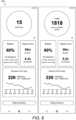
controller 204 would not count these five puffs in the session mode as the number of puffs exceeds the correction threshold. Therefore, even though the total number of puffs taken by the user is fifteen, no indication is provided to the user. Fig. 6 shows a graphical representation of a vaping profile of the user. In the present example, the app provided on the smartphone linked with thee-cig 100 generates avaping profile 600 of the user. As can be seen, thevaping profile 600 shows the total number of puffs taken by the user in the current puff session as well as the total quantity of steam or aerosol inhaled by the user in that day. In addition, there is information relating to vaping time and total number of sessions for that day with hourly analysis shown by a line graph. Theprofile 600 may also show the remaining battery level of thee-cig 100 and indicate the number of remaining sessions or vaping time left with the current battery usage. It is to be noted that the user's vaping history is monitored irrespective of the mode of operation.- Therefore, in both the session mode and the free mode, the user may be able to see the overall vaping profile on the app.
- It is to be understand that the above described device and the method may be modified according to design choices and manufacturer's preferences. For example, modes of operation may be changed based on other positional orientations of the device. Moreover, the timing control and puff counting sequence may be altered. In addition, various thresholds and preset values may be either hard coded or user configurable.
- The
controller 204 may also regulate aerosol delivery to increase or decrease the substance in the aerosol and/or add flavours to the aerosol depending on the user's preference. The amount of substance in the aerosol can be modified (increased or decreased) in a number of ways. In one example, the amount of aerosol released from theconsumable item 201b may be changed, thereby affecting the quantity of substance to be inhaled by the user. In another example, a multi-tank vaping device may be used which includes two or more liquid reservoirs each containing a liquid with different concentration of substance. By switching supply to the reservoir containing a different concentration liquid, it is possible to regulate the substance intake while maintaining the same aerosol amount. In yet another example, substance delivery can be modified by controlling the heating operation (e.g., by controlling the energy supplied to a heater) in heat-not-burn and vapour-based devices, or controlling a pressurized liquid source in vapour-based devices. - The processing steps described herein carried out by the main control unit, or controller, may be stored in a non-transitory computer-readable medium, or storage, associated with the main control unit. A computer-readable medium can include non-volatile media and volatile media. Volatile media can include semiconductor memories and dynamic memories, amongst others. Non-volatile media can include optical disks and magnetic disks, amongst others.
- The foregoing description of illustrative embodiments has been presented for purposes of illustration and of description. It is not intended to be exhaustive or limiting with respect to the precise form disclosed, and modifications and variations are possible in light of the above teachings or may be acquired from practice of the disclosed embodiments.
- As used herein, the term "non-transitory computer-readable media" is intended to be representative of any tangible computer-based device implemented in any method or technology for short-term and long-term storage of information, such as, computer-readable instructions, data structures, program modules and submodules, or other data in any device. Therefore, the methods described herein may be encoded as executable instructions embodied in a tangible, non-transitory, computer readable medium, including, without limitation, a storage device, and/or a memory device. Such instructions, when executed by a processor, cause the processor to perform at least a portion of the methods described herein. Moreover, as used herein, the term "non-transitory computer-readable media" includes all tangible, computer-readable media, including, without limitation, non-transitory computer storage devices, including, without limitation, volatile and non-volatile media, and removable and non-removable media such as a firmware, physical and virtual storage, CD-ROMs, DVDs, and any other digital source such as a network or the Internet, as well as yet to be developed digital means, with the sole exception being a transitory, propagating signal.
- As will be appreciated based on the foregoing specification, the above-described embodiments of the disclosure may be implemented using computer programming or engineering techniques including computer software, firmware, hardware or any combination or subset thereof. Any such resulting program, having computer-readable code means, may be embodied or provided within one or more computer-readable media, thereby making a computer program product, i.e., an article of manufacture, according to the discussed embodiments of the disclosure. The article of manufacture containing the computer code may be made and/or used by executing the code directly from one medium, by copying the code from one medium to another medium, or by transmitting the code over a network.
Claims (13)
- A method of operating an aerosol-generating device comprising:determining a positional orientation of the device when in use;monitoring usage of the device;activating a first mode of operation when the device is determined to be in a first orientation, wherein in the first mode providing a first indication to a user when the usage of the device reaches a first threshold; andactivating a second mode of operation when the device is determined to be in a second orientation, wherein in the second mode providing no indication to the user.
- The method of claim 1, wherein the first indication is provided only when the usage of the device in the first orientation reaches the first threshold.
- The method of claim 1, further comprising retaining the first mode if the device is determined to be in the second orientation for less than a preset period of time and is returned to the first orientation within the preset period.
- The method of claim 1, further comprising retaining the first mode if the usage of the device, when in the second orientation, is less than a preset number of puffs before the device is returned to the first orientation.
- The method of claim 1 or 2, further comprising determining whether the device is in the first orientation at least once during a predetermined period of use and if so, providing a second indication to the user at the end of the predetermined period of use.
- The method of claim 5, wherein the second indication is provided to the user when the usage of the device during the predetermined period of use reaches a second threshold.
- The method of claim 6, further comprising identifying an aerosol source to automatically set the second threshold based on the aerosol source.
- The method of claim 6, further comprising receiving an input from the user to set the second threshold.
- The method of any of claims 6 to 8, further comprising providing the second indication to the user when the usage of the device reaches the second threshold after the predetermined period of use irrespective of active mode of operation.
- The method of any preceding claim, further comprising counting a number of puffs to determine the usage of the device, wherein each puff is associated with a time stamp to analyse the usage over time.
- The method of claim 10, further comprising receiving an input from the user setting a number of puffs in a session as the first threshold for the first mode and if during the session the setting is changed by the user then resetting the puff count to zero.
- The method of any preceding claim, wherein the difference between the first orientation and the second orientation is 180 degrees along the longitudinal axis of the device.
- An aerosol-generating device (100) comprising:a body (101) having an inlet and an outlet with an air channel defined between the inlet and the outlet;an orientation sensor (208) configured to detect a positional orientation of the device when in use;a controller (204) configured to:monitor usage of the device;activate a first mode of operation when the device is detected to be in a first orientation, wherein in the first mode an indication is provided to a user when the usage of the device reaches a first threshold; andactivate a second mode of operation when the device is detected to be in a second orientation, wherein in the second mode no indication is provided to the user.
Priority Applications (15)
| Application Number | Priority Date | Filing Date | Title |
|---|---|---|---|
| PL20171187.6TPL3900554T3 (en) | 2020-04-23 | 2020-04-23 | How an aerosol-generating device works |
| EP20171187.6AEP3900554B1 (en) | 2020-04-23 | 2020-04-23 | Method of operating an aerosol-generating device |
| US17/919,633US20230172278A1 (en) | 2020-04-23 | 2021-04-20 | Method of Operating an Aerosol-Generating Device |
| JP2022552974AJP7645897B2 (en) | 2020-04-23 | 2021-04-20 | Method of operating an aerosol generating device |
| CA3171286ACA3171286A1 (en) | 2020-04-23 | 2021-04-20 | Method of operating an aerosol-generating device |
| EA202190829AEA202190829A3 (en) | 2020-04-23 | 2021-04-20 | METHOD OF OPERATION OF AEROSOL GENERATING DEVICE |
| CN202180021054.4ACN115297744B (en) | 2020-04-23 | 2021-04-20 | Method of operating an aerosol generating device |
| KR1020227040942AKR20230002984A (en) | 2020-04-23 | 2021-04-20 | How to operate an aerosol generating device |
| US17/918,800US20230144873A1 (en) | 2020-04-23 | 2021-04-20 | Method of Operating an Aerosol-Generating Device |
| JP2022564263AJP2023522277A (en) | 2020-04-23 | 2021-04-20 | Method of operating an aerosol generator |
| KR1020227035882AKR20230002422A (en) | 2020-04-23 | 2021-04-20 | How to operate an aerosol generating device |
| PCT/EP2021/060231WO2021214052A1 (en) | 2020-04-23 | 2021-04-20 | Method of operating an aerosol-generating device |
| PCT/EP2021/060230WO2021214051A1 (en) | 2020-04-23 | 2021-04-20 | Method of operating an aerosol-generating device |
| CN202180030262.0ACN115460944A (en) | 2020-04-23 | 2021-04-20 | A method of operating an aerosol generating device |
| CA3116017ACA3116017C (en) | 2020-04-23 | 2021-04-23 | Method of operating an aerosol-generating device |
Applications Claiming Priority (1)
| Application Number | Priority Date | Filing Date | Title |
|---|---|---|---|
| EP20171187.6AEP3900554B1 (en) | 2020-04-23 | 2020-04-23 | Method of operating an aerosol-generating device |
Publications (2)
| Publication Number | Publication Date |
|---|---|
| EP3900554A1 EP3900554A1 (en) | 2021-10-27 |
| EP3900554B1true EP3900554B1 (en) | 2023-08-23 |
Family
ID=70470797
Family Applications (1)
| Application Number | Title | Priority Date | Filing Date |
|---|---|---|---|
| EP20171187.6AActiveEP3900554B1 (en) | 2020-04-23 | 2020-04-23 | Method of operating an aerosol-generating device |
Country Status (9)
| Country | Link |
|---|---|
| US (1) | US20230172278A1 (en) |
| EP (1) | EP3900554B1 (en) |
| JP (1) | JP7645897B2 (en) |
| KR (1) | KR20230002422A (en) |
| CN (1) | CN115297744B (en) |
| CA (1) | CA3116017C (en) |
| EA (1) | EA202190829A3 (en) |
| PL (1) | PL3900554T3 (en) |
| WO (1) | WO2021214052A1 (en) |
Families Citing this family (4)
| Publication number | Priority date | Publication date | Assignee | Title |
|---|---|---|---|---|
| US20240206559A1 (en)* | 2021-07-23 | 2024-06-27 | Jt International Sa | Method of Operating an Aerosol Generating Device |
| EP4436422A1 (en)* | 2021-11-26 | 2024-10-02 | JT International SA | Aerosol generating device with an orientation sensor |
| GB202200785D0 (en)* | 2022-01-21 | 2022-03-09 | Nicoventures Trading Ltd | Aerosol provision system |
| CN118591311A (en)* | 2022-01-27 | 2024-09-03 | 日本烟草国际股份公司 | Aerosol generating device including an orientation sensor |
Family Cites Families (11)
| Publication number | Priority date | Publication date | Assignee | Title |
|---|---|---|---|---|
| US20070036348A1 (en)* | 2005-07-28 | 2007-02-15 | Research In Motion Limited | Movement-based mode switching of a handheld device |
| US9149589B2 (en)* | 2009-02-23 | 2015-10-06 | Trudell Medical International | Method and device for performing orientation dependent oscillating positive expiratory pressure therapy |
| KR102177660B1 (en)* | 2011-08-16 | 2020-11-12 | 쥴 랩스, 인크. | Low temperature electronic vaporization device and methods |
| US11696604B2 (en)* | 2014-03-13 | 2023-07-11 | Rai Strategic Holdings, Inc. | Aerosol delivery device and related method and computer program product for controlling an aerosol delivery device based on input characteristics |
| CN106302970A (en)* | 2015-06-03 | 2017-01-04 | 北京壹人壹本信息科技有限公司 | A kind of automatic mode switching method, system and communication terminal |
| MX2018009446A (en)* | 2016-02-12 | 2018-09-21 | Philip Morris Products Sa | Aerosol-generating system with puff detector. |
| FR3050618B1 (en)* | 2016-05-02 | 2023-12-15 | Sarl Gaiatrend | METHOD FOR CONTROLLING A VAPING DEVICE AND VAPING DEVICE FOR IMPLEMENTING THE METHOD |
| EP3610742A4 (en)* | 2017-04-11 | 2021-04-21 | KT & G Coporation | Aerosol generating device and method for providing smoking restriction function in aerosol generating device |
| CN110547505B (en) | 2018-05-30 | 2022-03-22 | 常州市派腾电子技术服务有限公司 | Electronic cigarette, cigarette liquid quantity obtaining method and device |
| TWI822798B (en)* | 2018-06-15 | 2023-11-21 | 美商尤爾實驗室有限公司 | Session control for a vaporizer device |
| US20200305511A1 (en)* | 2019-03-29 | 2020-10-01 | Loop Laboratories, LLC | Inhalant dispensing system and apparatus with binary dosing |
- 2020
- 2020-04-23EPEP20171187.6Apatent/EP3900554B1/enactiveActive
- 2020-04-23PLPL20171187.6Tpatent/PL3900554T3/enunknown
- 2021
- 2021-04-20EAEA202190829Apatent/EA202190829A3/enunknown
- 2021-04-20KRKR1020227035882Apatent/KR20230002422A/enactivePending
- 2021-04-20WOPCT/EP2021/060231patent/WO2021214052A1/ennot_activeCeased
- 2021-04-20USUS17/919,633patent/US20230172278A1/enactivePending
- 2021-04-20CNCN202180021054.4Apatent/CN115297744B/enactiveActive
- 2021-04-20JPJP2022552974Apatent/JP7645897B2/enactiveActive
- 2021-04-23CACA3116017Apatent/CA3116017C/enactiveActive
Also Published As
| Publication number | Publication date |
|---|---|
| US20230172278A1 (en) | 2023-06-08 |
| CA3116017C (en) | 2022-07-26 |
| CN115297744A (en) | 2022-11-04 |
| JP2023521944A (en) | 2023-05-26 |
| CN115297744B (en) | 2025-09-09 |
| EA202190829A2 (en) | 2021-10-29 |
| JP7645897B2 (en) | 2025-03-14 |
| KR20230002422A (en) | 2023-01-05 |
| EA202190829A3 (en) | 2021-12-31 |
| EP3900554A1 (en) | 2021-10-27 |
| WO2021214052A1 (en) | 2021-10-28 |
| PL3900554T3 (en) | 2024-04-08 |
| CA3116017A1 (en) | 2021-07-03 |
Similar Documents
| Publication | Publication Date | Title |
|---|---|---|
| EP3900554B1 (en) | Method of operating an aerosol-generating device | |
| KR102132466B1 (en) | Electronic inhalation device | |
| AU2020236492B2 (en) | Electronic aerosol provision system | |
| US20230144873A1 (en) | Method of Operating an Aerosol-Generating Device | |
| EP3900553B1 (en) | Method of operating an aerosol-generating device | |
| US20240206559A1 (en) | Method of Operating an Aerosol Generating Device | |
| EP4149302A1 (en) | Method of providing notifications on an aerosol-generating device | |
| EP4181713B1 (en) | Method of managing an aerosol-generating device | |
| US20230270176A1 (en) | Method of Managing an Aerosol-Generating Device | |
| EA042567B1 (en) | METHOD OF OPERATION OF AEROSOL GENERATING DEVICE | |
| EP4149301A1 (en) | Method of providing notifications on an aerosol-generating device |
Legal Events
| Date | Code | Title | Description |
|---|---|---|---|
| PUAI | Public reference made under article 153(3) epc to a published international application that has entered the european phase | Free format text:ORIGINAL CODE: 0009012 | |
| STAA | Information on the status of an ep patent application or granted ep patent | Free format text:STATUS: REQUEST FOR EXAMINATION WAS MADE | |
| 17P | Request for examination filed | Effective date:20210315 | |
| AK | Designated contracting states | Kind code of ref document:A1 Designated state(s):AL AT BE BG CH CY CZ DE DK EE ES FI FR GB GR HR HU IE IS IT LI LT LU LV MC MK MT NL NO PL PT RO RS SE SI SK SM TR | |
| B565 | Issuance of search results under rule 164(2) epc | Effective date:20200929 | |
| STAA | Information on the status of an ep patent application or granted ep patent | Free format text:STATUS: EXAMINATION IS IN PROGRESS | |
| 17Q | First examination report despatched | Effective date:20220114 | |
| GRAP | Despatch of communication of intention to grant a patent | Free format text:ORIGINAL CODE: EPIDOSNIGR1 | |
| STAA | Information on the status of an ep patent application or granted ep patent | Free format text:STATUS: GRANT OF PATENT IS INTENDED | |
| INTG | Intention to grant announced | Effective date:20230321 | |
| GRAS | Grant fee paid | Free format text:ORIGINAL CODE: EPIDOSNIGR3 | |
| GRAA | (expected) grant | Free format text:ORIGINAL CODE: 0009210 | |
| STAA | Information on the status of an ep patent application or granted ep patent | Free format text:STATUS: THE PATENT HAS BEEN GRANTED | |
| P01 | Opt-out of the competence of the unified patent court (upc) registered | Effective date:20230621 | |
| AK | Designated contracting states | Kind code of ref document:B1 Designated state(s):AL AT BE BG CH CY CZ DE DK EE ES FI FR GB GR HR HU IE IS IT LI LT LU LV MC MK MT NL NO PL PT RO RS SE SI SK SM TR | |
| REG | Reference to a national code | Ref country code:GB Ref legal event code:FG4D | |
| REG | Reference to a national code | Ref country code:CH Ref legal event code:EP | |
| REG | Reference to a national code | Ref country code:IE Ref legal event code:FG4D | |
| REG | Reference to a national code | Ref country code:DE Ref legal event code:R096 Ref document number:602020016053 Country of ref document:DE | |
| REG | Reference to a national code | Ref country code:RO Ref legal event code:EPE | |
| REG | Reference to a national code | Ref country code:LT Ref legal event code:MG9D | |
| REG | Reference to a national code | Ref country code:NL Ref legal event code:MP Effective date:20230823 | |
| REG | Reference to a national code | Ref country code:AT Ref legal event code:MK05 Ref document number:1601500 Country of ref document:AT Kind code of ref document:T Effective date:20230823 | |
| PG25 | Lapsed in a contracting state [announced via postgrant information from national office to epo] | Ref country code:IS Free format text:LAPSE BECAUSE OF FAILURE TO SUBMIT A TRANSLATION OF THE DESCRIPTION OR TO PAY THE FEE WITHIN THE PRESCRIBED TIME-LIMIT Effective date:20231223 | |
| REG | Reference to a national code | Ref country code:GR Ref legal event code:EP Ref document number:20230402255 Country of ref document:GR Effective date:20240110 | |
| PG25 | Lapsed in a contracting state [announced via postgrant information from national office to epo] | Ref country code:SE Free format text:LAPSE BECAUSE OF FAILURE TO SUBMIT A TRANSLATION OF THE DESCRIPTION OR TO PAY THE FEE WITHIN THE PRESCRIBED TIME-LIMIT Effective date:20230823 Ref country code:RS Free format text:LAPSE BECAUSE OF FAILURE TO SUBMIT A TRANSLATION OF THE DESCRIPTION OR TO PAY THE FEE WITHIN THE PRESCRIBED TIME-LIMIT Effective date:20230823 Ref country code:PT Free format text:LAPSE BECAUSE OF FAILURE TO SUBMIT A TRANSLATION OF THE DESCRIPTION OR TO PAY THE FEE WITHIN THE PRESCRIBED TIME-LIMIT Effective date:20231226 Ref country code:NO Free format text:LAPSE BECAUSE OF FAILURE TO SUBMIT A TRANSLATION OF THE DESCRIPTION OR TO PAY THE FEE WITHIN THE PRESCRIBED TIME-LIMIT Effective date:20231123 Ref country code:NL Free format text:LAPSE BECAUSE OF FAILURE TO SUBMIT A TRANSLATION OF THE DESCRIPTION OR TO PAY THE FEE WITHIN THE PRESCRIBED TIME-LIMIT Effective date:20230823 Ref country code:LV Free format text:LAPSE BECAUSE OF FAILURE TO SUBMIT A TRANSLATION OF THE DESCRIPTION OR TO PAY THE FEE WITHIN THE PRESCRIBED TIME-LIMIT Effective date:20230823 Ref country code:LT Free format text:LAPSE BECAUSE OF FAILURE TO SUBMIT A TRANSLATION OF THE DESCRIPTION OR TO PAY THE FEE WITHIN THE PRESCRIBED TIME-LIMIT Effective date:20230823 Ref country code:IS Free format text:LAPSE BECAUSE OF FAILURE TO SUBMIT A TRANSLATION OF THE DESCRIPTION OR TO PAY THE FEE WITHIN THE PRESCRIBED TIME-LIMIT Effective date:20231223 Ref country code:HR Free format text:LAPSE BECAUSE OF FAILURE TO SUBMIT A TRANSLATION OF THE DESCRIPTION OR TO PAY THE FEE WITHIN THE PRESCRIBED TIME-LIMIT Effective date:20230823 Ref country code:FI Free format text:LAPSE BECAUSE OF FAILURE TO SUBMIT A TRANSLATION OF THE DESCRIPTION OR TO PAY THE FEE WITHIN THE PRESCRIBED TIME-LIMIT Effective date:20230823 Ref country code:AT Free format text:LAPSE BECAUSE OF FAILURE TO SUBMIT A TRANSLATION OF THE DESCRIPTION OR TO PAY THE FEE WITHIN THE PRESCRIBED TIME-LIMIT Effective date:20230823 | |
| PG25 | Lapsed in a contracting state [announced via postgrant information from national office to epo] | Ref country code:ES Free format text:LAPSE BECAUSE OF FAILURE TO SUBMIT A TRANSLATION OF THE DESCRIPTION OR TO PAY THE FEE WITHIN THE PRESCRIBED TIME-LIMIT Effective date:20230823 | |
| PG25 | Lapsed in a contracting state [announced via postgrant information from national office to epo] | Ref country code:SM Free format text:LAPSE BECAUSE OF FAILURE TO SUBMIT A TRANSLATION OF THE DESCRIPTION OR TO PAY THE FEE WITHIN THE PRESCRIBED TIME-LIMIT Effective date:20230823 Ref country code:ES Free format text:LAPSE BECAUSE OF FAILURE TO SUBMIT A TRANSLATION OF THE DESCRIPTION OR TO PAY THE FEE WITHIN THE PRESCRIBED TIME-LIMIT Effective date:20230823 Ref country code:EE Free format text:LAPSE BECAUSE OF FAILURE TO SUBMIT A TRANSLATION OF THE DESCRIPTION OR TO PAY THE FEE WITHIN THE PRESCRIBED TIME-LIMIT Effective date:20230823 Ref country code:DK Free format text:LAPSE BECAUSE OF FAILURE TO SUBMIT A TRANSLATION OF THE DESCRIPTION OR TO PAY THE FEE WITHIN THE PRESCRIBED TIME-LIMIT Effective date:20230823 Ref country code:SK Free format text:LAPSE BECAUSE OF FAILURE TO SUBMIT A TRANSLATION OF THE DESCRIPTION OR TO PAY THE FEE WITHIN THE PRESCRIBED TIME-LIMIT Effective date:20230823 | |
| REG | Reference to a national code | Ref country code:DE Ref legal event code:R097 Ref document number:602020016053 Country of ref document:DE | |
| PLBE | No opposition filed within time limit | Free format text:ORIGINAL CODE: 0009261 | |
| STAA | Information on the status of an ep patent application or granted ep patent | Free format text:STATUS: NO OPPOSITION FILED WITHIN TIME LIMIT | |
| 26N | No opposition filed | Effective date:20240524 | |
| PG25 | Lapsed in a contracting state [announced via postgrant information from national office to epo] | Ref country code:SI Free format text:LAPSE BECAUSE OF FAILURE TO SUBMIT A TRANSLATION OF THE DESCRIPTION OR TO PAY THE FEE WITHIN THE PRESCRIBED TIME-LIMIT Effective date:20230823 | |
| PG25 | Lapsed in a contracting state [announced via postgrant information from national office to epo] | Ref country code:BG Free format text:LAPSE BECAUSE OF FAILURE TO SUBMIT A TRANSLATION OF THE DESCRIPTION OR TO PAY THE FEE WITHIN THE PRESCRIBED TIME-LIMIT Effective date:20230823 | |
| PG25 | Lapsed in a contracting state [announced via postgrant information from national office to epo] | Ref country code:MC Free format text:LAPSE BECAUSE OF FAILURE TO SUBMIT A TRANSLATION OF THE DESCRIPTION OR TO PAY THE FEE WITHIN THE PRESCRIBED TIME-LIMIT Effective date:20230823 | |
| PG25 | Lapsed in a contracting state [announced via postgrant information from national office to epo] | Ref country code:MC Free format text:LAPSE BECAUSE OF FAILURE TO SUBMIT A TRANSLATION OF THE DESCRIPTION OR TO PAY THE FEE WITHIN THE PRESCRIBED TIME-LIMIT Effective date:20230823 Ref country code:BG Free format text:LAPSE BECAUSE OF FAILURE TO SUBMIT A TRANSLATION OF THE DESCRIPTION OR TO PAY THE FEE WITHIN THE PRESCRIBED TIME-LIMIT Effective date:20230823 | |
| PG25 | Lapsed in a contracting state [announced via postgrant information from national office to epo] | Ref country code:LU Free format text:LAPSE BECAUSE OF NON-PAYMENT OF DUE FEES Effective date:20240423 | |
| REG | Reference to a national code | Ref country code:BE Ref legal event code:MM Effective date:20240430 | |
| PG25 | Lapsed in a contracting state [announced via postgrant information from national office to epo] | Ref country code:LU Free format text:LAPSE BECAUSE OF NON-PAYMENT OF DUE FEES Effective date:20240423 | |
| PG25 | Lapsed in a contracting state [announced via postgrant information from national office to epo] | Ref country code:BE Free format text:LAPSE BECAUSE OF NON-PAYMENT OF DUE FEES Effective date:20240430 | |
| PG25 | Lapsed in a contracting state [announced via postgrant information from national office to epo] | Ref country code:BE Free format text:LAPSE BECAUSE OF NON-PAYMENT OF DUE FEES Effective date:20240430 | |
| PG25 | Lapsed in a contracting state [announced via postgrant information from national office to epo] | Ref country code:IE Free format text:LAPSE BECAUSE OF NON-PAYMENT OF DUE FEES Effective date:20240423 | |
| PGFP | Annual fee paid to national office [announced via postgrant information from national office to epo] | Ref country code:PL Payment date:20250411 Year of fee payment:6 Ref country code:DE Payment date:20250422 Year of fee payment:6 | |
| PGFP | Annual fee paid to national office [announced via postgrant information from national office to epo] | Ref country code:GB Payment date:20250423 Year of fee payment:6 | |
| PGFP | Annual fee paid to national office [announced via postgrant information from national office to epo] | Ref country code:IT Payment date:20250424 Year of fee payment:6 | |
| PGFP | Annual fee paid to national office [announced via postgrant information from national office to epo] | Ref country code:FR Payment date:20250425 Year of fee payment:6 | |
| PGFP | Annual fee paid to national office [announced via postgrant information from national office to epo] | Ref country code:GR Payment date:20250423 Year of fee payment:6 | |
| PGFP | Annual fee paid to national office [announced via postgrant information from national office to epo] | Ref country code:CH Payment date:20250501 Year of fee payment:6 | |
| PGFP | Annual fee paid to national office [announced via postgrant information from national office to epo] | Ref country code:RO Payment date:20250414 Year of fee payment:6 | |
| PGFP | Annual fee paid to national office [announced via postgrant information from national office to epo] | Ref country code:CZ Payment date:20250414 Year of fee payment:6 | |
| PG25 | Lapsed in a contracting state [announced via postgrant information from national office to epo] | Ref country code:CY Free format text:LAPSE BECAUSE OF FAILURE TO SUBMIT A TRANSLATION OF THE DESCRIPTION OR TO PAY THE FEE WITHIN THE PRESCRIBED TIME-LIMIT; INVALID AB INITIO Effective date:20200423 | |
| PG25 | Lapsed in a contracting state [announced via postgrant information from national office to epo] | Ref country code:HU Free format text:LAPSE BECAUSE OF FAILURE TO SUBMIT A TRANSLATION OF THE DESCRIPTION OR TO PAY THE FEE WITHIN THE PRESCRIBED TIME-LIMIT; INVALID AB INITIO Effective date:20200423 |