EP3895627A1 - Surgical stapler cartridge comprising a lockout key - Google Patents
Surgical stapler cartridge comprising a lockout keyDownload PDFInfo
- Publication number
- EP3895627A1 EP3895627A1EP21172299.6AEP21172299AEP3895627A1EP 3895627 A1EP3895627 A1EP 3895627A1EP 21172299 AEP21172299 AEP 21172299AEP 3895627 A1EP3895627 A1EP 3895627A1
- Authority
- EP
- European Patent Office
- Prior art keywords
- anvil
- patent application
- surgical
- cartridge
- entitled
- Prior art date
- Legal status (The legal status is an assumption and is not a legal conclusion. Google has not performed a legal analysis and makes no representation as to the accuracy of the status listed.)
- Withdrawn
Links
Images


Classifications
- A—HUMAN NECESSITIES
- A61—MEDICAL OR VETERINARY SCIENCE; HYGIENE
- A61B—DIAGNOSIS; SURGERY; IDENTIFICATION
- A61B17/00—Surgical instruments, devices or methods
- A61B17/068—Surgical staplers, e.g. containing multiple staples or clamps
- A61B17/0682—Surgical staplers, e.g. containing multiple staples or clamps for applying U-shaped staples or clamps, e.g. without a forming anvil
- A—HUMAN NECESSITIES
- A61—MEDICAL OR VETERINARY SCIENCE; HYGIENE
- A61B—DIAGNOSIS; SURGERY; IDENTIFICATION
- A61B17/00—Surgical instruments, devices or methods
- A61B17/068—Surgical staplers, e.g. containing multiple staples or clamps
- A61B17/072—Surgical staplers, e.g. containing multiple staples or clamps for applying a row of staples in a single action, e.g. the staples being applied simultaneously
- A61B17/07207—Surgical staplers, e.g. containing multiple staples or clamps for applying a row of staples in a single action, e.g. the staples being applied simultaneously the staples being applied sequentially
- A—HUMAN NECESSITIES
- A61—MEDICAL OR VETERINARY SCIENCE; HYGIENE
- A61B—DIAGNOSIS; SURGERY; IDENTIFICATION
- A61B17/00—Surgical instruments, devices or methods
- A61B17/28—Surgical forceps
- A61B17/29—Forceps for use in minimally invasive surgery
- A—HUMAN NECESSITIES
- A61—MEDICAL OR VETERINARY SCIENCE; HYGIENE
- A61B—DIAGNOSIS; SURGERY; IDENTIFICATION
- A61B17/00—Surgical instruments, devices or methods
- A61B17/34—Trocars; Puncturing needles
- A—HUMAN NECESSITIES
- A61—MEDICAL OR VETERINARY SCIENCE; HYGIENE
- A61B—DIAGNOSIS; SURGERY; IDENTIFICATION
- A61B90/00—Instruments, implements or accessories specially adapted for surgery or diagnosis and not covered by any of the groups A61B1/00 - A61B50/00, e.g. for luxation treatment or for protecting wound edges
- A61B90/39—Markers, e.g. radio-opaque or breast lesions markers
- A—HUMAN NECESSITIES
- A61—MEDICAL OR VETERINARY SCIENCE; HYGIENE
- A61F—FILTERS IMPLANTABLE INTO BLOOD VESSELS; PROSTHESES; DEVICES PROVIDING PATENCY TO, OR PREVENTING COLLAPSING OF, TUBULAR STRUCTURES OF THE BODY, e.g. STENTS; ORTHOPAEDIC, NURSING OR CONTRACEPTIVE DEVICES; FOMENTATION; TREATMENT OR PROTECTION OF EYES OR EARS; BANDAGES, DRESSINGS OR ABSORBENT PADS; FIRST-AID KITS
- A61F2/00—Filters implantable into blood vessels; Prostheses, i.e. artificial substitutes or replacements for parts of the body; Appliances for connecting them with the body; Devices providing patency to, or preventing collapsing of, tubular structures of the body, e.g. stents
- A61F2/82—Devices providing patency to, or preventing collapsing of, tubular structures of the body, e.g. stents
- A—HUMAN NECESSITIES
- A61—MEDICAL OR VETERINARY SCIENCE; HYGIENE
- A61B—DIAGNOSIS; SURGERY; IDENTIFICATION
- A61B17/00—Surgical instruments, devices or methods
- A61B17/10—Surgical instruments, devices or methods for applying or removing wound clamps, e.g. containing only one clamp or staple; Wound clamp magazines
- A61B17/105—Wound clamp magazines
- A—HUMAN NECESSITIES
- A61—MEDICAL OR VETERINARY SCIENCE; HYGIENE
- A61B—DIAGNOSIS; SURGERY; IDENTIFICATION
- A61B17/00—Surgical instruments, devices or methods
- A61B17/32—Surgical cutting instruments
- A—HUMAN NECESSITIES
- A61—MEDICAL OR VETERINARY SCIENCE; HYGIENE
- A61B—DIAGNOSIS; SURGERY; IDENTIFICATION
- A61B17/00—Surgical instruments, devices or methods
- A61B2017/00017—Electrical control of surgical instruments
- A—HUMAN NECESSITIES
- A61—MEDICAL OR VETERINARY SCIENCE; HYGIENE
- A61B—DIAGNOSIS; SURGERY; IDENTIFICATION
- A61B17/00—Surgical instruments, devices or methods
- A61B2017/00367—Details of actuation of instruments, e.g. relations between pushing buttons, or the like, and activation of the tool, working tip, or the like
- A61B2017/00398—Details of actuation of instruments, e.g. relations between pushing buttons, or the like, and activation of the tool, working tip, or the like using powered actuators, e.g. stepper motors, solenoids
- A—HUMAN NECESSITIES
- A61—MEDICAL OR VETERINARY SCIENCE; HYGIENE
- A61B—DIAGNOSIS; SURGERY; IDENTIFICATION
- A61B17/00—Surgical instruments, devices or methods
- A61B2017/0046—Surgical instruments, devices or methods with a releasable handle; with handle and operating part separable
- A—HUMAN NECESSITIES
- A61—MEDICAL OR VETERINARY SCIENCE; HYGIENE
- A61B—DIAGNOSIS; SURGERY; IDENTIFICATION
- A61B17/00—Surgical instruments, devices or methods
- A61B2017/0046—Surgical instruments, devices or methods with a releasable handle; with handle and operating part separable
- A61B2017/00473—Distal part, e.g. tip or head
- A—HUMAN NECESSITIES
- A61—MEDICAL OR VETERINARY SCIENCE; HYGIENE
- A61B—DIAGNOSIS; SURGERY; IDENTIFICATION
- A61B17/00—Surgical instruments, devices or methods
- A61B2017/00477—Coupling
- A—HUMAN NECESSITIES
- A61—MEDICAL OR VETERINARY SCIENCE; HYGIENE
- A61B—DIAGNOSIS; SURGERY; IDENTIFICATION
- A61B17/00—Surgical instruments, devices or methods
- A61B2017/00681—Aspects not otherwise provided for
- A61B2017/00734—Aspects not otherwise provided for battery operated
- A—HUMAN NECESSITIES
- A61—MEDICAL OR VETERINARY SCIENCE; HYGIENE
- A61B—DIAGNOSIS; SURGERY; IDENTIFICATION
- A61B17/00—Surgical instruments, devices or methods
- A61B2017/00831—Material properties
- A61B2017/00862—Material properties elastic or resilient
- A—HUMAN NECESSITIES
- A61—MEDICAL OR VETERINARY SCIENCE; HYGIENE
- A61B—DIAGNOSIS; SURGERY; IDENTIFICATION
- A61B17/00—Surgical instruments, devices or methods
- A61B17/068—Surgical staplers, e.g. containing multiple staples or clamps
- A61B2017/0688—Packages or dispensers for surgical staplers
- A—HUMAN NECESSITIES
- A61—MEDICAL OR VETERINARY SCIENCE; HYGIENE
- A61B—DIAGNOSIS; SURGERY; IDENTIFICATION
- A61B17/00—Surgical instruments, devices or methods
- A61B17/068—Surgical staplers, e.g. containing multiple staples or clamps
- A61B17/072—Surgical staplers, e.g. containing multiple staples or clamps for applying a row of staples in a single action, e.g. the staples being applied simultaneously
- A61B2017/07214—Stapler heads
- A61B2017/07221—Stapler heads curved
- A—HUMAN NECESSITIES
- A61—MEDICAL OR VETERINARY SCIENCE; HYGIENE
- A61B—DIAGNOSIS; SURGERY; IDENTIFICATION
- A61B17/00—Surgical instruments, devices or methods
- A61B17/068—Surgical staplers, e.g. containing multiple staples or clamps
- A61B17/072—Surgical staplers, e.g. containing multiple staples or clamps for applying a row of staples in a single action, e.g. the staples being applied simultaneously
- A61B2017/07214—Stapler heads
- A61B2017/07228—Arrangement of the staples
- A—HUMAN NECESSITIES
- A61—MEDICAL OR VETERINARY SCIENCE; HYGIENE
- A61B—DIAGNOSIS; SURGERY; IDENTIFICATION
- A61B17/00—Surgical instruments, devices or methods
- A61B17/068—Surgical staplers, e.g. containing multiple staples or clamps
- A61B17/072—Surgical staplers, e.g. containing multiple staples or clamps for applying a row of staples in a single action, e.g. the staples being applied simultaneously
- A61B2017/07214—Stapler heads
- A61B2017/07257—Stapler heads characterised by its anvil
- A—HUMAN NECESSITIES
- A61—MEDICAL OR VETERINARY SCIENCE; HYGIENE
- A61B—DIAGNOSIS; SURGERY; IDENTIFICATION
- A61B17/00—Surgical instruments, devices or methods
- A61B17/068—Surgical staplers, e.g. containing multiple staples or clamps
- A61B17/072—Surgical staplers, e.g. containing multiple staples or clamps for applying a row of staples in a single action, e.g. the staples being applied simultaneously
- A61B2017/07214—Stapler heads
- A61B2017/07271—Stapler heads characterised by its cartridge
- A—HUMAN NECESSITIES
- A61—MEDICAL OR VETERINARY SCIENCE; HYGIENE
- A61B—DIAGNOSIS; SURGERY; IDENTIFICATION
- A61B17/00—Surgical instruments, devices or methods
- A61B17/068—Surgical staplers, e.g. containing multiple staples or clamps
- A61B17/072—Surgical staplers, e.g. containing multiple staples or clamps for applying a row of staples in a single action, e.g. the staples being applied simultaneously
- A61B2017/07214—Stapler heads
- A61B2017/07278—Stapler heads characterised by its sled or its staple holder
- A—HUMAN NECESSITIES
- A61—MEDICAL OR VETERINARY SCIENCE; HYGIENE
- A61B—DIAGNOSIS; SURGERY; IDENTIFICATION
- A61B17/00—Surgical instruments, devices or methods
- A61B17/068—Surgical staplers, e.g. containing multiple staples or clamps
- A61B17/072—Surgical staplers, e.g. containing multiple staples or clamps for applying a row of staples in a single action, e.g. the staples being applied simultaneously
- A61B2017/07214—Stapler heads
- A61B2017/07285—Stapler heads characterised by its cutter
- A—HUMAN NECESSITIES
- A61—MEDICAL OR VETERINARY SCIENCE; HYGIENE
- A61B—DIAGNOSIS; SURGERY; IDENTIFICATION
- A61B17/00—Surgical instruments, devices or methods
- A61B17/28—Surgical forceps
- A61B17/29—Forceps for use in minimally invasive surgery
- A61B17/2909—Handles
- A61B2017/2925—Pistol grips
- A—HUMAN NECESSITIES
- A61—MEDICAL OR VETERINARY SCIENCE; HYGIENE
- A61B—DIAGNOSIS; SURGERY; IDENTIFICATION
- A61B17/00—Surgical instruments, devices or methods
- A61B17/28—Surgical forceps
- A61B17/29—Forceps for use in minimally invasive surgery
- A61B2017/2926—Details of heads or jaws
- A—HUMAN NECESSITIES
- A61—MEDICAL OR VETERINARY SCIENCE; HYGIENE
- A61B—DIAGNOSIS; SURGERY; IDENTIFICATION
- A61B17/00—Surgical instruments, devices or methods
- A61B17/28—Surgical forceps
- A61B17/29—Forceps for use in minimally invasive surgery
- A61B2017/2926—Details of heads or jaws
- A61B2017/2927—Details of heads or jaws the angular position of the head being adjustable with respect to the shaft
- A—HUMAN NECESSITIES
- A61—MEDICAL OR VETERINARY SCIENCE; HYGIENE
- A61B—DIAGNOSIS; SURGERY; IDENTIFICATION
- A61B17/00—Surgical instruments, devices or methods
- A61B17/28—Surgical forceps
- A61B17/29—Forceps for use in minimally invasive surgery
- A61B2017/2926—Details of heads or jaws
- A61B2017/2932—Transmission of forces to jaw members
- A61B2017/2933—Transmission of forces to jaw members camming or guiding means
- A61B2017/2936—Pins in guiding slots
- A—HUMAN NECESSITIES
- A61—MEDICAL OR VETERINARY SCIENCE; HYGIENE
- A61B—DIAGNOSIS; SURGERY; IDENTIFICATION
- A61B17/00—Surgical instruments, devices or methods
- A61B17/28—Surgical forceps
- A61B17/29—Forceps for use in minimally invasive surgery
- A61B2017/2926—Details of heads or jaws
- A61B2017/2932—Transmission of forces to jaw members
- A61B2017/2939—Details of linkages or pivot points
- A—HUMAN NECESSITIES
- A61—MEDICAL OR VETERINARY SCIENCE; HYGIENE
- A61B—DIAGNOSIS; SURGERY; IDENTIFICATION
- A61B17/00—Surgical instruments, devices or methods
- A61B17/28—Surgical forceps
- A61B17/29—Forceps for use in minimally invasive surgery
- A61B2017/2946—Locking means
- A—HUMAN NECESSITIES
- A61—MEDICAL OR VETERINARY SCIENCE; HYGIENE
- A61B—DIAGNOSIS; SURGERY; IDENTIFICATION
- A61B90/00—Instruments, implements or accessories specially adapted for surgery or diagnosis and not covered by any of the groups A61B1/00 - A61B50/00, e.g. for luxation treatment or for protecting wound edges
- A61B90/03—Automatic limiting or abutting means, e.g. for safety
- A61B2090/033—Abutting means, stops, e.g. abutting on tissue or skin
- A61B2090/034—Abutting means, stops, e.g. abutting on tissue or skin abutting on parts of the device itself
- A—HUMAN NECESSITIES
- A61—MEDICAL OR VETERINARY SCIENCE; HYGIENE
- A61B—DIAGNOSIS; SURGERY; IDENTIFICATION
- A61B90/00—Instruments, implements or accessories specially adapted for surgery or diagnosis and not covered by any of the groups A61B1/00 - A61B50/00, e.g. for luxation treatment or for protecting wound edges
- A61B90/08—Accessories or related features not otherwise provided for
- A61B2090/0807—Indication means
- A61B2090/0808—Indication means for indicating correct assembly of components, e.g. of the surgical apparatus
- A—HUMAN NECESSITIES
- A61—MEDICAL OR VETERINARY SCIENCE; HYGIENE
- A61B—DIAGNOSIS; SURGERY; IDENTIFICATION
- A61B90/00—Instruments, implements or accessories specially adapted for surgery or diagnosis and not covered by any of the groups A61B1/00 - A61B50/00, e.g. for luxation treatment or for protecting wound edges
- A61B90/08—Accessories or related features not otherwise provided for
- A61B2090/0807—Indication means
- A61B2090/0811—Indication means for the position of a particular part of an instrument with respect to the rest of the instrument, e.g. position of the anvil of a stapling instrument
- A—HUMAN NECESSITIES
- A61—MEDICAL OR VETERINARY SCIENCE; HYGIENE
- A61B—DIAGNOSIS; SURGERY; IDENTIFICATION
- A61B90/00—Instruments, implements or accessories specially adapted for surgery or diagnosis and not covered by any of the groups A61B1/00 - A61B50/00, e.g. for luxation treatment or for protecting wound edges
- A61B90/08—Accessories or related features not otherwise provided for
- A61B2090/0814—Preventing re-use
- A—HUMAN NECESSITIES
- A61—MEDICAL OR VETERINARY SCIENCE; HYGIENE
- A61B—DIAGNOSIS; SURGERY; IDENTIFICATION
- A61B90/00—Instruments, implements or accessories specially adapted for surgery or diagnosis and not covered by any of the groups A61B1/00 - A61B50/00, e.g. for luxation treatment or for protecting wound edges
- A61B90/39—Markers, e.g. radio-opaque or breast lesions markers
- A61B2090/3966—Radiopaque markers visible in an X-ray image
- A—HUMAN NECESSITIES
- A61—MEDICAL OR VETERINARY SCIENCE; HYGIENE
- A61B—DIAGNOSIS; SURGERY; IDENTIFICATION
- A61B34/00—Computer-aided surgery; Manipulators or robots specially adapted for use in surgery
- A61B34/30—Surgical robots
- A—HUMAN NECESSITIES
- A61—MEDICAL OR VETERINARY SCIENCE; HYGIENE
- A61B—DIAGNOSIS; SURGERY; IDENTIFICATION
- A61B34/00—Computer-aided surgery; Manipulators or robots specially adapted for use in surgery
- A61B34/30—Surgical robots
- A61B34/37—Leader-follower robots
- A—HUMAN NECESSITIES
- A61—MEDICAL OR VETERINARY SCIENCE; HYGIENE
- A61B—DIAGNOSIS; SURGERY; IDENTIFICATION
- A61B90/00—Instruments, implements or accessories specially adapted for surgery or diagnosis and not covered by any of the groups A61B1/00 - A61B50/00, e.g. for luxation treatment or for protecting wound edges
- A61B90/90—Identification means for patients or instruments, e.g. tags
Definitions
- Various exemplary devices and methodsare provided for performing laparoscopic and minimally invasive surgical procedures.
- the various methods and devices disclosed hereincan be used in numerous surgical procedures and applications including, for example, in connection with open surgical procedures.
- the various instruments disclosed hereincan be inserted into a body in any way, such as through a natural orifice, through an incision or puncture hole formed in tissue, etc.
- the working portions or end effector portions of the instrumentscan be inserted directly into a patient's body or can be inserted through an access device that has a working channel through which the end effector and elongate shaft of a surgical instrument can be advanced.
- the shaft assembly 1200can include a proximal portion which is fixably mounted to the handle 1014 and a distal portion which is rotatable about a longitudinal axis.
- the rotatable distal shaft portioncan be rotated relative to the proximal portion about the slip ring assembly 1600, as discussed above.
- the distal connector flange of the slip ring assembly 1600can be positioned within the rotatable distal shaft portion.
- the switch drum 1500can also be positioned within the rotatable distal shaft portion. When the rotatable distal shaft portion is rotated, the distal connector flange and the switch drum 1500 can be rotated synchronously with one another.
- the switch drum 1500can be rotated between a first position and a second position relative to the distal connector flange.
- the articulation drive systemWhen the switch drum 1500 is in its first position, the articulation drive system may be operably disengaged from the firing drive system and, thus, the operation of the firing drive system may not articulate the end effector 1300 of the shaft assembly 1200.
- the switch drum 1500When the switch drum 1500 is in its second position, the articulation drive system may be operably engaged with the firing drive system and, thus, the operation of the firing drive system may articulate the end effector 1300 of the shaft assembly 1200.
- the switch drum 1500When the switch drum 1500 is moved between its first position and its second position, the switch drum 1500 is moved relative to distal connector flange.
- the shaft assembly 1200can comprise at least one sensor configured to detect the position of the switch drum 1500.
- the secondary drive shaft 5050is connected to a drive gear 5054 that engages a proximate drive gear 5056 of the helical screw shaft 5036.
- the vertical bevel gear 5052bmay sit and pivot in an opening 5057 in the distal end of the proximate spine tube 5046.
- a distal spine tube 5058may be used to enclose the secondary drive shaft 5050 and the drive gears 5054, 5056.
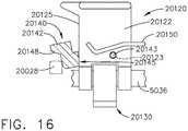
- the lockout member 20142is pivotally coupled to the firing member body 20122 by pivot pins 20143 that are received in a hole 20123 extending through the firing member body 20122. See FIGS. 14 and 16 .
- the pivot pins 20143are sized relative to the holes 20123 in the firing member body 20122 to facilitate free pivotal travel of the lockout member 20142 and to account for tolerance differences of the components.
- the firing member 20120includes a proximally-facing, firing surface 20145 that is configured to abut a distal-facing bearing surface 20125 on the firing member body 20122 when the firing member lockout assembly 20140 is in the unlocked position.
- Axial movement of the end effector closure tube 3050 in a distal directionwill cause the anvil 20400 to pivot to a closed position about a pivot axis defined by the anvil trunnions 20412 and movement of the end effector closure tube 3050 in a proximal direction will cause the anvil to pivot to an open position relative to the elongate channel 20310.
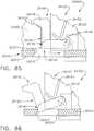
- the firing member 20500As the user distally advances the firing member 20500 into the cartridge 20600, the firing member 20500 also drives the camming assembly therein which cams the drivers upward to drive the staples or fasteners supported thereon into forming contact with the underside of the anvil. The tissue cutting member 20504 on the firing member 20500 then cuts through the stapled tissue.
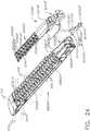
- FIG. 24illustrates an alternative closure lockout system 20700" for preventing an anvil 20400" of another surgical end effector 20300" from being moved from an open position to a closed (clamped) position unless a compatible surgical staple cartridge 20600" has been operably installed in the elongate channel 20310.
- the surgical end effector 20300"is substantially identical to surgical end effector 20300 described above, except for the differences discussed below.
- the closure lockout system 20700"comprises an anvil lockout 20702" that is substantially identical to anvil lockout 20702 described above, except for the following differences.
- the location, shape, length, etc. of the anvil unlocking feature(s) or tab(s) on a surgical staple cartridgemay vary from cartridge type to cartridge type and be interrelated to the actuator member (size, location, shape, number, etc.) on the correspond anvil lockout located in a corresponding surgical end effector.
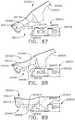
- the extension spring 21730biases the anvil lock 21702 into a distal locked position wherein the locking tab portion 21710 contacts a portion of the anvil 21400 to prevent the anvil 21400 from pivoting to a closed position.
- the unlocking feature or tab 21630 of the cartridge pan 21620contacts the actuation tab 21712 on the anvil lock 21702 to move the anvil lock 21702 proximally into an unlocked position wherein the locking tab portion 21710 of the anvil lock 21702 no longer prevents pivotal motion of the anvil 21400.
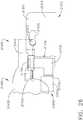
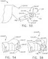
- FIG. 30illustrates portions of a surgical end effector 21300' that is identical to end effector 21300, except that the end effector 21300' employs an anvil lock 21702' as depicted in FIGS. 31 and 32 .
- the anvil lock 21702'may be fabricated from 40% carbon filled Nylon 6/6 and include a vertical body portion 21706' that has a locking portion 21710' formed on the upper end thereof.
- An actuation tab 21712'is formed on a distal end and a gusset 21714' is also employed to provide additional support to the actuation tab 21712'.
- a channel stop 22313"is formed on a bottom 22312" of the channel 22310" and is configured for contact with a proximal end 22711" of the anvil lock 22702" to prevent the cartridge 22600 from being inserted too far proximally into the end effector 22300".
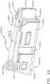
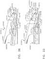
- FIGS. 39 and 40illustrate another surgical end effector 23300 that is similar to the other surgical end effectors described herein with the exception of the various differences noted below.
- the end effector 23300comprises an elongate channel 23310 that includes an anvil 23400 that is pivotally supported thereon.
- the channel 23310is configured to operably support a surgical staple cartridge 22600 that is compatible to the staple-forming undersurface of the anvil 23400 and employs an anvil locking system 23700 that is configured to prevent closure of the anvil 23400 unless a cartridge 22600 has been operably installed in the end effector 23300.
- anvil locking system 23700comprises an anvil lock 23702 comprising a body portion 23706 that has a distal end portion 23712.
- anvil lock 24702' of the anvil locking system 24700'operates in the same manner as the anvil lock 20702 described above and includes a lockout body 24706' that has an actuator tab (not shown) formed on a distal end thereof that is configured to be contacted by an unlocking feature that protrudes proximally from a compatible cartridge.
- the anvil lock 24702'may be fabricated from spring steel or other suitable metal and include a proximal biasing arm 24704' that may be configured to be seated in a transverse spring mounting slot (not shown) provided in the body portion of a channel mount feature (not shown).
- the anvil lock 24702'further includes an upwardly extending anvil lockout tab 24710' that protrudes therefrom that is configured to extend above the corresponding lobe ledge 24340' and contact a corresponding lobe 24414' as was described above.
- FIGS. 63 and 68illustrate the surgical end effector 25300 without a surgical staple cartridge installed therein.
- the proximal biasing arm 25704has biased the closure lock 25702 downward in the channel 25310 which results in the blocking feature 25710 moving into blocking alignment with the distal end 3051 of the end effector closure tube 3050 (locked position).
- the blocking feature 25710will block the distal advancement of the end effector closure tube 3050 thereby preventing an application of closure motions to the anvil 25400.
- the unlocking feature 25660"has a tapered nose portion 25662" that is configured to operably interact with the actuation tab 25712" so that the when the tapered nose portion 25662" is brought into engagement with the actuation tab 25712", the closure lock 25702" is moved upward against a downward biasing force established by the lower spring 25720".
- the anvil locking tab 25710" on the closure lock 25702is no longer in blocking alignment with the lock lug 25414" on the anvil mounting portion 24410".
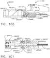
- FIGS. 103 and 104illustrate insertion of the incompatible cartridge 26600X' into the end effector 26300' wherein the incompatible cartridge 26600X' has been initially inserted too far proximally into the channel 26310' such that the distal end of the firing member 20500 has contacted and pushed the camming assembly 26650' or "sled" too far distally within the cartridge 26600X' so as to be in the appropriate position to unlockingly engage the sled latch 20514 portion of the firing member 20500 after the cartridge 26600X' has ultimately been seated in the channel 26310' in a proper position.
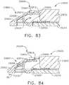
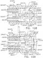
- FIG. 110illustrates a proximal end portion 27604 of a surgical staple cartridge 27600 that is compatible with the surgical end effector 27300.
- the surgical staple cartridge 27600comprises an elongate cartridge body 27602 that is sized to be removably seated in the elongate channel 27310.
- the cartridge body 27602includes a cartridge slot 27608 that extends from the proximal end portion 27604 to a distal end portion of the cartridge body 27602.
- the cartridge body 27602further comprises a cartridge deck surface 27610 that confronts a staple-forming undersurface of the anvil when the cartridge 27600 is seated in the channel 27310 and the anvil is pivoted to a closed position.
- the surgical staple cartridge 27600may have a plurality of (usually three) lines of surgical staple pockets on each side of the cartridge slot 27608 that open through the cartridge deck surface 27610.
- Each staple pocketmay have a staple driver (not shown) associated therewith that supports a surgical staple or fastener (not shown) thereon.
- the cartridge body 27602is molded from a polymer material with the staple pockets molded or machined therein.
- the staple pocketsalso open through a bottom of the cartridge body 27602 to facilitate installation of the drivers and fasteners into their respective pockets.
- a cartridge pan 27620is attached to the bottom of the cartridge body 27602. When installed, the cartridge pan 27620 may, among other things, prevent the drivers and fasteners from falling out of the bottom of the cartridge body 27602 during handling and installation of the cartridge 27600 into the elongate channel 27310.
- the end effector closure tubemay be configured to bias the verification shuttle to the locked, blocking position when the closure member is actuated to close the anvil.
- the cartridge verification system 27440may also be effectively employed with surgical end effectors that have rotary powered firing member arrangements with firing member lockout systems of the types disclosed herein.
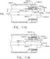
- the cartridge 28600is equipped with a camming assembly locking system 28440 that is configured to retain the camming assembly 28650 in its starting position unless the cartridge 28600 has been loaded into a compatible end effector.
- the camming assembly locking system 28440comprises a laterally displaceable lock feature 28442 that comprises an actuator portion 28444 and a locking tab 28446.
- the locking tab 28446is configured to be received within a lock cavity 28655 provided in a corresponding cam member 28654' when the camming assembly 28650 is in a locked position. See FIGS. 116 and 117 .
- the firing member 30040is biased toward the channel 30010 by a spring and, if the sled 30030 is not in its unfired position when the firing member 30040 is advanced distally to start the staple firing stroke, the distal nose 30043 of the cutting portion 30042 will miss, or not land on, the shoulder 30033 and the cutting portion 30042 will dive downwardly toward the channel 30010 instead.
- the cutting portion 30042comprises lockout pins 30045 extending laterally therefrom which enter a lockout window, or recess, 30012 defined in the channel 30010 when the distal nose 30043 does not land on the shoulder 30033 of the sled 30030.
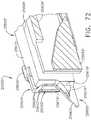
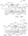
- a surgical instrument 30100is illustrated in FIG. 122 and includes an improvement which can reduce the possibility of the distal nose 30043 of the cutting portion 30042 missing the shoulder 30033 of the sled 30030.
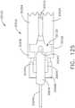
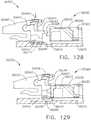
- the surgical instrument 30100is similar to the surgical instrument 30000 in many respects but includes a staple cartridge 30120 instead of the staple cartridge 30020.
- the staple cartridge 30120comprises a cartridge body 30122, staple cavities defined in the cartridge body 30122, and staples removably stored in the staple cavities. Referring to FIG.
- the staple cartridge 30120further comprises a sled 30030 which, similar to the above, is movable distally from an unfired position during a staple firing stroke if the distal nose 30043 of the cutting portion 30042 catches the shoulder 30033 of the sled 30030. If not, referring to FIG. 124 , the cutting portion 30042 is pushed into the lockout window 30012 defined in the cartridge channel 30010 when the firing member 30040 is advanced distally.
- the proximal end of the cartridge body 30022does not engage, and/or sufficiently displace, the lock arms 30516.
- the staple cartridge 30020would be an improper staple cartridge as it does not unlock the staple firing drive of the stapling instrument 30500 and, correspondingly, the staple cartridge 30520 would be a proper staple cartridge as it can unlock the staple firing drive of the stapling instrument 30500.
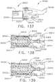
- the firing lockout 30514is both a missing cartridge lockout and an improper cartridge lockout.
- the stapling instrument 30500can further comprise a spent cartridge lockout.
- the lock shoulder 30015is robustly designed to absorb this impact; however, there exists a possibility that the firing member 30040 can plow or blow through the lock shoulder 30015 thereby unintentionally defeating the staple firing lockout of the stapling instrument 30000.
- the lockout 30514 of FIGS. 136 and 137can reduce, if not eliminate, these potential problems.
- the lock windows 30515 of the firing lockout 30514are sized and configured to prevent little, if any, proximal and distal translation of the staple firing member 30040 while the lock arms 30516 are engaged with the lockout pins 30045 and, thus, the staple firing member 30040 has little, if any, time to accelerate before being stopped by the distal ends of the lock windows 30515.
- the lock arms 30516are placed in tension and, as a result, are capable of handling significant loads before failing, if they fail at all.
- the staple cartridge 30700further comprises a cartridge body 30722 including a proximal end 30726 that is angled such that the laterals sides of the cartridge body 30722, i.e., the portions furthest away from the longitudinal slot 30023, extend further proximally than the center of the cartridge body 30722.
- the staple cartridge 30720further comprises a sled 30730, which is similar to the sled 30030 in many respects, that comprises a proximal end 30736 having a profile that matches, or at least substantially matches, the profile of the proximal end 30726 of the cartridge body 30722.
- the lockout 30814also comprises an anvil closure lockout as the lockout 30814 prevents the anvil 30050 from being closed when the staple cartridge 30820 is not seated in the cartridge channel 30810. In such instances, the clinician will become quickly aware that an improper staple cartridge is positioned in the cartridge channel 30810 and/or that a staple cartridge is missing altogether as they won't be able to close the anvil 30050.
- the lockout 30814is configured to resist the closure of the anvil 30050.
- the proximal end of the lockout 30814is fixedly supported in the cartridge channel 30810 and the distal end of the lockout 30814 is simply supported by the sidewalls of the window 30819.
- the lockout 30814can act as a beam supported at both ends and is well-suited to withstand the clamping load applied by the anvil 30050.
- the tab 30817 extending from the lockout 30814is also supported by the cartridge channel 30810.
- the tab 30817is slidably supported in a slot 30818 defined in the cartridge channel 30810 when the lockout 30814 is in both of its locked ( FIG. 153 ) and unlocked ( FIG. 154 ) configurations.
- the lockout 30814can act as a beam supported at both ends and an intermediate position and is well-suited to withstand the clamping load applied by the anvil 30050. That said, any suitable support arrangement could be used.
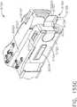
- a staple cartridge 31520is illustrated in FIG. 155A .
- the staple cartridge 31520comprises a cartridge body 31522 and a pan 31524 attached to the cartridge body 31522.
- the pan 31524comprises lock arms 31521 engaged with lateral channels defined in the cartridge body 31522 which hold the pan 31524 to the cartridge body 31522.
- the pan 31524is comprised of stamped metal, such as stainless steel, for example.
- the pan 31524comprises two lateral sides - one on each side of the longitudinal slot 30023. Each lateral side of the pan 31524 extends along a lateral side of the cartridge body 31522 and under a portion of the cartridge body 31522.
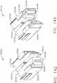
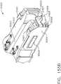
- the surgical stapling assembly 41000further comprises a lockout 41500 ( FIG. 160 ) configured to prevent the firing member 41400 from moving distally past a specific position unless a proper unspent staple cartridge is installed within the first jaw 41200 and the first jaw 41200 is in a fully clamped configuration.
- the firing member 41400is permitted to move a first distance between a home position and the specific position regardless of the condition of the lockout 41500 to permit clamping and unclamping of tissue, as discussed in greater detail below.
- the lockout 41500is biased toward a locked configuration where the firing member 41400 is prevented from moving distally beyond the specific position.
- the firing member 41400is permitted to move distally past an unfired location and into the staple cartridge 41230.
- the unfired locationis defined as the position after clamping but before firing.
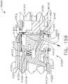
- the tool 41590can be disengaged from the lockout member 41510 and removed from the orifice 41425 to allow the lockout 41500 to resume normal operation.
- the lockout member 41510will pivot into the locked configuration when the firing member 41400 returns to the unfired location after having at least partially fired a staple cartridge.
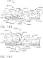
- the lockout 42300, and its position relative to other components of the surgical stapling assembly 42000,is also directly visible through the direct access cutout 42210. Nonetheless, a tool can be inserted through the cutout 42210 to pull and/or push the lockout 42300 proximally to overcome the spring bias and move the lockout 42300 into the unlocked configuration. The tool can also be removed and disengaged from the lockout 42300 such that the lockout 42300 can resume normal operation. Moreover, providing the ability to manually move the lockout 42300 may allow a clinician to move the lockout 42300 away from its locked position before installing a staple cartridge into the cartridge channel 42200 to prevent the lockout 42300 from moving a sled of the staple cartridge that is being installed into the cartridge channel 42200 prematurely.
- the firing assembly 43100comprises a firing shaft 43110 and a firing member 43120 attached to the distal end of the firing shaft 43110. Although a linear firing shaft is illustrated, the firing assembly 43100 may be configured with a rotary drive shaft.
- the firing shaft 43110is configured to be actuated by a firing driver of a surgical instrument handle and/or a surgical robot, for example. Any suitable drive mechanism may be used.
- the firing member 43120comprises anvil-camming pins 43122 and channel camming pins 43123 extending laterally therefrom.
- the pins 43122, 43123are configured to control the clamping pressure on the tissue captured within the surgical stapling assembly 43000 during a firing stroke.
- the firing member 43120further comprises a cutting edge 43121 configured to cut the clamped tissue.
- the firing member 43120further comprises a ledge, or distal nose, 43124 configured to engage and/or rest on top of a sled of an unfired proper staple cartridge such that the firing member 43120 does not fall into the lock
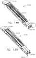
- the proximal longitudinal slot portion 45333is configured to straddle the firing member 45520 when the staple cartridge 45300 is installed in the channel 45210.
- Each protrusion of the lockout key 45330comprises a ramped surface, or portion, 45331 and a non-ramped portion, or surface, 45332.
- the staple cartridge 45300further comprises a pan 45320 configured to hold the staples within the cartridge body 45310.
- the pan 45320is configured to clip onto a deck 45312 of the cartridge body 45310.
- the pan 45320may be removably affixed to the cartridge body 45310 by a series of hooks 45321 that are formed on the sidewalls of the cartridge pan 45320 and configured to hookingly engage corresponding portions of the cartridge body 45310.
- the pancan comprise the lockout key.
- FIG. 176illustrates the staple cartridge 45300 installed within the channel 45210; however, the sled 45340 is not present in its unfired position.
- the firing shaft 45510is not sufficiently lifted upwardly by the floating pin 45600 to lift the firing shaft 45510 out of the lockout. Instead, the firing shaft 45510 is pulled down by the spring 45240 as the firing assembly 45500 is advanced distally owing to the floating pin 45600 fitting in the notch 45515.
- the improper cartridgemust be removed and replaced with a proper unfired staple cartridge.
- reconditioning of a devicecan utilize a variety of techniques for disassembly, cleaning/replacement, and reassembly. Use of such techniques, and the resulting reconditioned device, are all within the scope of the present application.
- the devices disclosed hereinmay be processed before surgery.
- a new or used instrumentmay be obtained and, when necessary, cleaned.
- the instrumentmay then be sterilized.
- the instrumentis placed in a closed and sealed container, such as a plastic or TYVEK bag.
- the container and instrumentmay then be placed in a field of radiation that can penetrate the container, such as gamma radiation, x-rays, and/or high-energy electrons.
- the radiationmay kill bacteria on the instrument and in the container.
- the sterilized instrumentmay then be stored in the sterile container.
- the sealed containermay keep the instrument sterile until it is opened in a medical facility.
- a devicemay also be sterilized using any other technique known in the art, including but not limited to beta radiation, gamma radiation, ethylene oxide, plasma peroxide, and/or steam.
Landscapes
- Health & Medical Sciences (AREA)
- Life Sciences & Earth Sciences (AREA)
- Surgery (AREA)
- Engineering & Computer Science (AREA)
- Biomedical Technology (AREA)
- General Health & Medical Sciences (AREA)
- Veterinary Medicine (AREA)
- Heart & Thoracic Surgery (AREA)
- Public Health (AREA)
- Animal Behavior & Ethology (AREA)
- Nuclear Medicine, Radiotherapy & Molecular Imaging (AREA)
- Medical Informatics (AREA)
- Molecular Biology (AREA)
- Pathology (AREA)
- Oral & Maxillofacial Surgery (AREA)
- Ophthalmology & Optometry (AREA)
- Transplantation (AREA)
- Vascular Medicine (AREA)
- Cardiology (AREA)
- Surgical Instruments (AREA)
Abstract
Description
- This application claims the benefit of U.S. Provisional Patent Application Serial No.
62/807,310 62/807,319 62/807,309 U.S. Provisional Patent Application Serial No. 62/650,887 U.S. Provisional Patent Application Serial No. 62/649,302 U.S. Provisional Patent Application Serial No. 62/649,294 U.S. Provisional Patent Application Serial No. 62/649,300 U.S. Provisional Patent Application Serial No. 62/649,309 U.S. Provisional Patent Application Serial No. 62/649,310 U.S. Provisional Patent Application Serial No. 62/649,291 U.S. Provisional Patent Application Serial No. 62/649,296 62/649,333 62/649,327 62/649,315 62/649,313 62/649,320 62/649,307 62/649,323 - The present invention relates to surgical instruments and, in various arrangements, to surgical stapling and cutting instruments and staple cartridges for use therewith that are designed to staple and cut tissue.
- Various features of the embodiments described herein, together with advantages thereof, may be understood in accordance with the following description taken in conjunction with the accompanying drawings as follows:
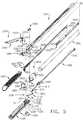
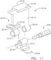
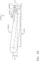
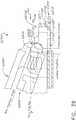
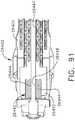
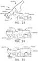
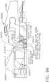
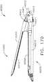
FIG. 1 is a perspective view of a powered surgical stapling system;FIG. 2 is a perspective view of an interchangeable surgical shaft assembly of the powered surgical stapling system ofFIG. 1 ;FIG. 3 is an exploded assembly view of portions of a handle assembly of the powered surgical stapling system ofFIG. 1 ;FIG. 4 is an exploded assembly view of the interchangeable surgical shaft assembly ofFIG. 2 ;FIG. 5 is another partial exploded assembly view of a portion of the interchangeable surgical shaft assembly ofFIG. 4 ;FIG. 6 is a perspective view of another powered surgical stapling system;FIG. 7 is an exploded assembly view of portion of a shaft assembly of the powered surgical stapling system ofFIG. 6 ;FIG. 8 is an exploded assembly view of portions of a handle assembly of the powered surgical stapling system ofFIG. 6 ;FIG. 9 is a side elevational view of another surgical end effector that may be employed with a rotary powered surgical stapling system;FIG. 10 is an exploded assembly view of the surgical end effector ofFIG. 9 ;FIG. 11 is an exploded assembly view of a rotary powered firing member that may be employed with the surgical end effector ofFIGS. 9 and10 ;FIG. 12 is a partial cross-sectional view of the surgical end effector ofFIG. 9 illustrating initial insertion of a fresh, unfired surgical staple cartridge therein;FIG. 13 is another partial cross-sectional view of the surgical end effector ofFIG. 12 , after the surgical staple cartridge has been operably installed therein;FIG. 14 is an enlarged partial cross-sectional view illustrating a firing member and a camming assembly of the end effector ofFIG. 13 ;FIG. 15 is another partial cross-sectional view of the surgical end effector ofFIG. 9 , prior to insertion of a fresh surgical staple cartridge therein and with a firing member lockout assembly thereof in a locked position;FIG. 16 is an enlarged partial cross-sectional view illustrating a firing member and lockout lugs of the end effector ofFIG. 15 , with a camming assembly and end effector channel omitted for clarity;FIG. 17 is a side elevational view of another surgical end effector with an anvil thereof in an open position;FIG. 18 is a partial bottom perspective view of the surgical end effector ofFIG. 17 ;FIG. 19 is a perspective view of a channel mount feature and anvil lockout spring of the surgical end effector ofFIG. 17 ;FIG. 20 is a partial bottom perspective view of the surgical end effector ofFIG. 17 without a surgical staple cartridge installed therein and the anvil thereof in a locked position;FIG. 21 is another partial bottom perspective view of the surgical end effector ofFIG. 20 after a compatible surgical staple cartridge has been installed therein and the anvil lockout spring moved to an unlocked position;FIG. 22 is a perspective view of a proximal end portion of the surgical staple cartridge depicted inFIG. 21 ;FIG. 23 is a partial exploded assembly view of a surgical staple cartridge and a corresponding anvil and anvil lockout system of a surgical end effector;FIG. 24 is a partial exploded assembly view of a surgical staple cartridge and a corresponding anvil and anvil lockout system of another surgical end effector;FIG. 25 is a partial bottom view of a channel of another end effector with a compatible surgical staple cartridge loaded therein with portions of the compatible surgical staple cartridge omitted for clarity;FIG. 26 is a side elevational view of a portion of the surgical end effector ofFIG. 25 , with portions of a channel, anvil and cartridge omitted for clarity;FIG. 27 is a partial cross-sectional end view of the surgical end effector ofFIGS. 25 and26 with the anvil shown in a closed position on a compatible surgical staple cartridge;FIG. 28 is another partial cross-sectional end view of the surgical end effector ofFIGS. 25 and26 with the anvil thereof shown in a locked open position;FIG. 29 is a side elevational of an anvil lock of the surgical end effector ofFIGS. 25 and26 shown in a locked configuration and an unlocked configuration (in phantom lines);FIG. 30 is a side elevational view of a portion of another surgical end effector, with portions of a channel, anvil and cartridge omitted for clarity;FIG. 31 is a front elevational view of an anvil lock of the surgical end effector ofFIG. 30 ;FIG. 32 is a top view of the anvil lock ofFIG. 31 ;FIG. 33 is a cross-sectional side view of another surgical end effector with an anvil thereof in an open position and with a compatible surgical staple cartridge installed therein;FIG. 34 is a partial perspective view of a proximal end of a compatible surgical staple cartridge ofFIG. 33 in relation to a portion of an anvil lock feature of the surgical end effector ofFIG. 33 ;FIG. 35 is a top view of a portion of a channel of the surgical end effector ofFIG. 33 and an outline of a compatible surgical staple cartridge ofFIG. 33 being inserted therein;FIG. 36 is another cross-sectional side view of the surgical end effector ofFIG. 33 , with the anvil thereof in an open position during initial installation of an incompatible surgical staple cartridge therein;FIG. 37 is a cross-sectional side view of another surgical end effector with an anvil thereof in an open position during installation of a compatible surgical staple cartridge therein;FIG. 38 is a cross-sectional side view of portions of another surgical end effector with an anvil thereof in an open position during installation of a compatible surgical staple cartridge therein;FIG. 39 is a cross-sectional side view of portions of another surgical end effector with an anvil thereof in an open position during installation of a compatible surgical staple cartridge therein;FIG. 40 is a cross-sectional side view of the end effector ofFIG. 39 during installation of an incompatible cartridge therein;FIG. 41 is a partial perspective view of a proximal end portion of an anvil;FIG. 42 is a partial perspective view of a proximal end portion of another anvil;FIG. 43 is a partial cross-sectional end view of portions of another surgical end effector;FIG. 44 is a partial perspective view of a proximal end portion of the anvil of the surgical end effector ofFIG. 43 ;FIG. 45 is a partial cross-sectional perspective view of a portion of a channel and anvil lock of the surgical end effector ofFIG. 43 , with the anvil lock in a locked position;FIG. 46 is a partial side elevational view of the surgical end effector ofFIG. 43 with the anvil in an open position and the anvil lock thereof shown in a locked position in phantom lines;FIG. 47 is another partial cross-sectional perspective view of a portion of the channel and anvil lock of the surgical end effector ofFIG. 43 , with the anvil lock in an unlocked position;FIG. 48 is another partial side elevational view of the surgical end effector ofFIG. 43 with the anvil in a closed position and the anvil lock thereof shown in the unlocked position in phantom lines;FIG. 49 is a partial cross-sectional end view of portions of another surgical end effector;FIG. 50 is a partial perspective view of a proximal end portion of the anvil of the surgical end effector ofFIG. 49 ;FIG. 51 is a partial cross-sectional side view of a portion of a channel and anvil lock of the surgical end effector ofFIG. 49 , with the anvil lock in a locked position;FIG. 52 is a partial side elevational view of another surgical end effector with an anvil thereof in an open position and an anvil lock thereof shown in a locked position in phantom lines;FIG. 53 is a side elevational view of a portion of the anvil of the surgical end effector ofFIG. 52 ;FIG. 54 is a partial perspective view of a portion of the anvil ofFIG. 53 ;FIG. 55 is a partial cross-sectional perspective view of a portion of a channel and anvil lock of the surgical end effector ofFIG. 52 with the anvil lock in a locked position;FIG. 56 is another partial cross-sectional perspective view of a portion of the channel and anvil lock of the surgical end effector ofFIG. 52 , with the anvil lock in an unlocked position;FIG. 57 is a partial side elevational view of the surgical end effector ofFIG. 52 with the anvil in a closed position and the anvil lock thereof shown in the unlocked position in phantom lines;FIG. 58 is a partial perspective view of another anvil;FIG. 59 is a partial cross-sectional perspective view of a portion of another channel that may be used in connection with the anvil ofFIG. 58 ;FIG. 60 is a side elevational view of a portion of another anvil;FIG. 61 is a perspective view of a portion of the anvil ofFIG. 60 ;FIG. 62 is a perspective view of a portion of another anvil;FIG. 63 is a side elevational view of another surgical end effector with an anvil thereof in an open position prior to installation of a surgical staple cartridge therein;FIG. 64 is another side elevational view of the surgical end effector ofFIG. 63 after a compatible surgical staple cartridge has been installed therein;FIG. 65 is an end elevational view of an surgical end effector closure tube of the surgical end effector ofFIG. 63 and with a closure lock thereof in a locked position;FIG. 66 is another end elevational view of the surgical end effector closure tube and closure lock ofFIG. 65 , with the closure lock shown in an unlocked position;FIG. 67 is a partial perspective view of a portion of a compatible surgical staple cartridge and the closure lock of the surgical end effector ofFIG. 63 ;FIG. 68 is a partial side elevational view of the surgical end effector ofFIG. 63 with the anvil thereof in an open position and prior to installation of a surgical staple cartridge therein;FIG. 69 is another partial side elevational view of the surgical end effector ofFIG. 68 with the anvil thereof in an open position and during installation of a compatible surgical staple cartridge therein;FIG. 70 is a partial side elevational view of the surgical end effector ofFIG. 68 with the anvil thereof in an open position and during initial installation of a compatible surgical staple cartridge therein;FIG. 71 is another partial side elevational view of the surgical end effector ofFIG. 70 with the anvil thereof in an open position and after the compatible surgical staple cartridge has been operably seated therein;FIG. 72 is a partial cross-sectional perspective view of a portion of the compatible surgical staple cartridge shown inFIGS. 70 and 71 ;FIG. 73 is another partial side elevational view of the surgical end effector ofFIG. 70 with the anvil thereof in an open position and during installation thereof of a surgical staple cartridge lacking a compatible camming assembly in a starting position;FIG. 74 is a partial side elevational view of another surgical end effector with an anvil thereof in an open position and during initial installation of a compatible surgical staple cartridge therein;FIG. 75 is another partial side elevational view of the surgical end effector ofFIG. 74 with the anvil thereof in an open position and after the compatible surgical staple cartridge has been operably seated therein;FIG. 76 is a perspective view of an anvil lock and channel mounting feature of the surgical end effector ofFIGS. 74 and 75 ;FIG. 77 is a perspective view of a portion of a surgical staple cartridge that is compatible with the surgical end effector ofFIGS. 74 and 75 ;FIG. 78 is another partial side elevational view of the surgical end effector ofFIG. 74 with the anvil thereof in an open position and after an incompatible surgical staple cartridge has been seated therein;FIG. 79 is a side elevational view of another surgical end effector with a compatible surgical staple cartridge loaded therein and an anvil thereof in an open position;FIG. 80 is a top view of a portion of a surgical staple cartridge that is compatible with the surgical end effector ofFIG. 79 with portions thereof omitted for clarity;FIG. 81 is a partial cross-sectional side view of a portion of the surgical staple cartridge ofFIG. 80 installed in the surgical end effector ofFIG. 79 taken along line 81-81 inFIG. 80 showing the cartridge nose assembly in a locked position;FIG. 82 is another partial cross-sectional side view of a portion of the surgical staple cartridge ofFIG. 80 installed in the surgical end effector ofFIG. 79 taken along line 82-82 inFIG. 80 showing the cartridge nose assembly in an unlocked position;FIG. 83 is another partial cross-sectional side view of a portion of the surgical staple cartridge ofFIG. 80 installed in the surgical end effector ofFIG. 79 taken along line 83-83 inFIG. 80 showing the cartridge nose assembly in a locked position;FIG. 84 is another partial cross-sectional side view of a portion of the surgical staple cartridge ofFIG. 80 installed in the surgical end effector ofFIG. 79 taken along line 84-84 inFIG. 80 showing the cartridge nose assembly in an unlocked position;FIG. 85 is a partial cross-sectional view of a portion of a firing member and camming assembly of a surgical staple cartridge wherein the camming assembly is in a starting position and in unlocking engagement with a firing member lock on a firing member;FIG. 86 is another partial cross-sectional view of a portion of a firing member ofFIG. 85 , with the firing member lock in a locked position;FIG. 87 is a side elevational view of a portion of an anvil of another surgical end effector with the anvil in an open position in relation to compatible surgical staple cartridge installed within a corresponding channel that has been omitted for clarity;FIG. 88 is another side elevational view of the anvil and surgical staple cartridge ofFIG. 87 during initial closure of the anvil;FIG. 89 is another side elevational view of the anvil and surgical staple cartridge ofFIG. 87 after the anvil has been moved to a closed position;FIG. 90 is a perspective view of a portion of the compatible surgical staple cartridge depicted inFIGS. 87-89 ;FIG. 91 is a partial bottom view of the anvil ofFIGS. 87-89 ;FIG. 92 is a perspective view of a portion of surgical staple cartridge that is incompatible with the anvil ofFIGS. 87-89 ;FIG. 93 is a side elevational view of the anvil ofFIGS. 87-89 in an open position in relation to an incompatible surgical staple cartridge ofFIG. 92 installed within a corresponding channel that has been omitted for clarity;FIG. 94 is another side elevational view of the anvil and surgical staple cartridge ofFIG. 93 during initial closure of the anvil;FIG. 95 is another side elevational view of the anvil and surgical staple cartridge ofFIG. 93 after the anvil has been moved to a closed position;FIG. 96 is a partial cross-sectional side view of a portion of another surgical end effector with a compatible surgical staple cartridge loaded therein and an anvil thereof omitted for clarity;FIG. 97 is a top view of a portion of the surgical staple cartridge and surgical end effector ofFIG. 96 ;FIG. 98 is a perspective view of a portion of proximal end of a compatible surgical staple cartridge depicted inFIG. 97 ;FIG. 99 is another partial cross-sectional side view of a portion of the surgical end effector ofFIG. 96 illustrating the installation of a compatible surgical staple cartridge therein;FIG. 100 is another partial cross-sectional side view of a portion of the surgical end effector ofFIG. 96 illustrating the installation of a compatible surgical staple cartridge therein;FIG. 101 is a top view of the surgical end effector and compatible surgical staple cartridge ofFIG. 98 ;FIG. 102 is another partial cross-sectional side view of a portion of the surgical end effector ofFIG. 96 illustrating the installation of an incompatible surgical staple cartridge therein;FIG. 103 is another partial cross-sectional side view of a portion of the surgical end effector ofFIG. 96 illustrating the installation of an incompatible surgical staple cartridge therein;FIG. 104 is a top view of the surgical end effector and incompatible surgical staple cartridge ofFIG. 103 ;FIG. 105 is another partial cross-sectional side view of a portion of the surgical end effector ofFIG. 96 illustrating the installation of an incompatible surgical staple cartridge therein;FIG. 106 is a top view of the surgical end effector and incompatible surgical staple cartridge ofFIG. 105 ;FIG. 107 is a partial cross-sectional perspective view of portions of another surgical end effector with an incompatible surgical staple cartridge installed therein;FIG. 108 is a partial top view of portions of the surgical end effector an incompatible surgical staple cartridge ofFIG. 107 ;FIG. 109 is another partial top view of the surgical end effector ofFIG. 105 , with a compatible surgical staple cartridge installed therein;FIG. 110 is a partial cross-sectional perspective view of portions of another surgical end effector with a compatible surgical staple cartridge installed therein;FIG. 111 is a partial exploded assembly view of portions of the surgical end effector ofFIG. 110 ;FIG. 112 is a partial cross-sectional end view of the surgical end effector and compatible surgical staple cartridge ofFIG. 110 ;FIG. 113 is another partial cross-sectional surgical end view of the end effector ofFIG. 110 with an incompatible surgical staple cartridge installed therein;FIG. 114 is another partial cross-sectional perspective view of portions of the surgical end effector ofFIG. 110 with an incompatible surgical staple cartridge installed therein;FIG. 115 is a top view of the surgical end effector and surgical staple cartridge ofFIG. 114 ;FIG. 116 is a top view of a portion of another surgical staple cartridge;FIG. 117 is a partial cross-sectional perspective view of a portion of the surgical staple cartridge ofFIG. 116 with a camming assembly thereof in a locked position;FIG. 118 is another top view of the surgical staple cartridge ofFIG. 116 interacting with a compatible actuator portion of a surgical end effector;FIG. 119 is another partial cross-sectional perspective view of a portion of the surgical staple cartridge ofFIG. 116 with the camming assembly thereof in an unlocked position;FIG. 120 is a partial elevational view of a stapling instrument including a cartridge channel, a staple cartridge positioned in the cartridge channel, and a firing member in accordance with at least one embodiment illustrated with some components removed, wherein the firing member is in an unfired position;FIG. 121 is a partial elevational view of the stapling instrument ofFIG. 120 illustrating the firing member in a locked-out position;FIG. 122 is a partial elevational view of a stapling instrument including a cartridge channel, a staple cartridge positioned in the cartridge channel, and a firing member in accordance with at least one embodiment illustrated with some components removed, wherein the firing member is in an unfired position;FIG. 123 is a partial elevational view of the stapling instrument ofFIG. 122 illustrating the firing member in an unlocked position;FIG. 124 is a partial elevational view of the stapling instrument ofFIG. 122 illustrating the firing member in a locked-out position;FIG. 125 is a partial bottom view of the stapling instrument ofFIG. 122 illustrating the firing member in an unfired position;FIG. 126 is a partial perspective view of the staple cartridge ofFIG. 122 ;FIG. 127 is a partial perspective view of a staple cartridge in accordance with at least one embodiment;FIG. 128 is a partial elevational view of a stapling instrument including a cartridge channel, a staple cartridge positioned in the cartridge channel, and a firing member in accordance with at least one embodiment illustrated with some components removed, wherein the firing member is in an unfired position;FIG. 129 is a partial elevational view of the stapling instrument ofFIG. 128 illustrating the firing member in an unlocked position;FIG. 130 is a partial top view of the stapling instrument ofFIG. 128 illustrated in the unfired position ofFIG. 128 ;FIG. 131 is a partial top view of the stapling instrument ofFIG. 128 illustrated in the unlocked position ofFIG. 129 ;FIG. 132 is a partial perspective view of the staple cartridge ofFIG. 128 in an unspent configuration;FIG. 133 is a partial perspective view of the staple cartridge ofFIG. 128 in a spent configuration;FIG. 134 is a partial elevational view of a stapling instrument including a cartridge channel, a staple cartridge positioned in the cartridge channel, and a firing member in accordance with at least one embodiment illustrated with some components removed, wherein the firing member is in an unfired position;FIG. 135 is a partial elevational view of the stapling instrument ofFIG. 134 illustrating the firing member in a locked-out position;FIG. 136 is a partial perspective view of a stapling instrument including a cartridge channel, a staple cartridge positioned in the cartridge channel, a firing member, and a firing member lock in accordance with at least one embodiment illustrated with some components removed, wherein the firing member has been unlocked by the staple cartridge;FIG. 137 is a partial elevational view of the stapling instrument ofFIG. 136 illustrated with an improper staple cartridge seated in the cartridge channel;FIG. 138 is a partial cross-sectional plan view of the stapling instrument ofFIG. 136 illustrated with an improper staple cartridge seated in the cartridge channel;FIG. 139 is a partial cross-sectional plan view of the stapling instrument ofFIG. 136 illustrating the firing member lock unlocked by the staple cartridge;FIG. 140 is a partial cross-sectional view of a stapling instrument in accordance with at least one embodiment that has been unlocked by a staple cartridge;FIG. 141 is a partial cross-sectional view of a stapling instrument in accordance with at least one embodiment that has been unlocked by a staple cartridge;FIG. 142 is a partial perspective view of the staple cartridge ofFIG. 140 ;FIG. 143 is a partial perspective view of the staple cartridge ofFIG. 141 ;FIG. 144 is a partial cross-sectional perspective view of a staple cartridge pan in accordance with at least one embodiment;FIG. 145 is a partial perspective view of a stapling instrument including a cartridge channel, a staple cartridge positioned in the cartridge channel, a firing member, and a firing member lock in accordance with at least one embodiment illustrated with some components removed, wherein the firing member is unlocked by the staple cartridge;FIG. 146 is a partial perspective view of the stapling instrument ofFIG. 145 illustrating a different staple cartridge positioned in the cartridge channel which does not unlock the firing member;FIG. 147 is a partial perspective view of the stapling instrument ofFIG. 145 illustrating the firing member in a locked configuration;FIG. 148 is a partial perspective view of a stapling instrument configured to be unlocked by the different staple cartridge ofFIG. 146 ;FIG. 149 is a perspective view of a staple cartridge which is similar to the staple cartridge ofFIG. 146 and configured to unlock the stapling instrument ofFIG. 148 ;FIG. 150 is a perspective view of a staple cartridge which is similar to the staple cartridge ofFIG. 145 and configured to unlock the stapling instrument ofFIG. 145 ;FIG. 151 is a partial exploded view of a stapling instrument comprising a cartridge channel, a staple cartridge positioned in the cartridge channel, a firing member, an anvil, and a dual-purpose firing member/anvil lock in accordance with at least one embodiment illustrated with some components removed, wherein the stapling instrument is illustrated in a locked state;FIG. 152 is a partial perspective view of the stapling instrument ofFIG. 151 being unlocked by the insertion of the staple cartridge into the cartridge channel;FIG. 153 is a partial cross-sectional view of the stapling instrument ofFIG. 151 illustrating the stapling instrument in the locked state ofFIG. 151 ;FIG. 154 is a partial cross-sectional view of the stapling instrument ofFIG. 151 illustrating the stapling instrument in the unlocked state ofFIG. 152 ;FIG. 155 is a perspective view of the firing member/anvil lock ofFIG. 151 ;FIG. 155A is a partial perspective view of a staple cartridge in accordance with at least one embodiment;FIG. 155B is a partial perspective view of a staple cartridge in accordance with at least one embodiment;FIG. 155C is a partial perspective view of a staple cartridge in accordance with at least one embodiment;FIG. 155D is a partial perspective view of a staple cartridge in accordance with at least one embodiment;FIG. 155E is a partial perspective view of a staple cartridge in accordance with at least one embodiment;FIG. 156 is a partial cross-sectional view of a surgical stapling assembly comprising an anvil, a staple cartridge, a firing member, and a firing lockout;FIG. 157 is a partial cross-sectional view of the firing member and the firing lockout ofFIG. 156 illustrated in an unlocked configuration;FIG. 158 is a partial cross-sectional view of the firing member and the firing lockout ofFIG. 156 illustrated in a locked configuration;FIG. 159 is a partial cross-sectional view of the surgical stapling assembly ofFIG. 156 , wherein the surgical stapling assembly further comprises an exterior access aperture configured to permit a user to artificially move the firing lockout into the unlocked configuration with a separate lockout key;FIG. 160 is a perspective view of a lockout member of the firing lockout ofFIG. 156 ;FIG. 161 is a partial cross-sectional view of a surgical stapling assembly comprising a lockout and an exterior access orifice configured to permit a user to artificially move the firing lockout into an unlocked configuration with a separate lockout key;FIG. 162 is a bottom plan view of the surgical stapling assembly ofFIG. 161 ;FIG. 163 is a partial cross-sectional view of a surgical stapling assembly comprising a firing member, a cartridge channel, a staple cartridge configured be installed into the cartridge channel, and a lockout, wherein the lockout is illustrated in an unengaged configuration;FIG. 164 is a partial cross-sectional view of the surgical stapling assembly ofFIG. 163 , wherein the lockout is illustrated in an engaged configuration;FIG. 165 comprises elevational views of two staple cartridges each comprising a different lockout key;FIG. 166 is a graph depicting knife lift timing provided by each lockout key of the staple cartridges ofFIG. 165 ;FIG. 167 is a graph depicting knife lift displacement provided by each lockout key of the staple cartridges ofFIG. 165 ;FIG. 168 is a perspective view of a first staple cartridge for use with a surgical stapling system, wherein the first staple cartridge comprises a cartridge body, a pan, a sled, and a first lockout key;FIG. 169 is a perspective view of a second staple cartridge for use with the surgical stapling system with which the first staple cartridge ofFIG. 168 is to be used, wherein the second staple cartridge comprises a cartridge body, a pan, a sled, and a second lockout key;FIG. 170 is an elevational view of a surgical stapling assembly comprising a firing member, a first jaw comprising a staple cartridge, a second jaw comprising an anvil movable relative to the first jaw, and a lockout;FIG. 171 is partial perspective view of the surgical stapling assembly ofFIG. 170 ;FIG. 172 is a partial elevational view of the surgical stapling assembly ofFIG. 170 where the staple cartridge is not installed within the first jaw;FIG. 173 is a partial elevational view of the surgical stapling assembly ofFIG. 170 where the staple cartridge is installed within the first jaw;FIG. 174 is a partial cross-sectional view of the surgical stapling assembly ofFIG. 170 where the staple cartridge is installed within the first jaw and the firing member is in an unfired position;FIG. 175 is a partial cross-sectional view of the surgical stapling assembly ofFIG. 170 where the staple cartridge is installed within the first jaw and the firing member is in a partially fired position;FIG. 176 is a partial cross-sectional view of the surgical stapling assembly ofFIG. 170 where the staple cartridge is not installed within the first jaw and the firing member is in the unfired position;FIG. 177 is a partial cross-sectional view of the surgical stapling assembly ofFIG. 170 where the staple cartridge is not installed within the first jaw and the firing member is in a locked position;FIG. 178 is a partial elevational view of the surgical stapling assembly ofFIG. 170 where the staple cartridge is installed within the first jaw and the firing member is in the partially fired position, wherein some components are illustrated with hidden lines;FIG. 179 is a perspective view of the staple cartridge of the surgical stapling assembly ofFIG. 170 comprising a lockout key extending from a proximal end thereof;FIG. 180 is a partial plan view of the staple cartridge ofFIG. 179 ; andFIG. 181 is a partial plan view of a second staple cartridge configured for use with a system including the staple cartridge ofFIG. 179 , wherein the second staple cartridge comprises a lockout key comprising a different configuration than the lockout key of the staple cartridge ofFIG. 179 .- Corresponding reference characters indicate corresponding parts throughout the several views. The exemplifications set out herein illustrate various embodiments of the invention, in one form, and such exemplifications are not to be construed as limiting the scope of the invention in any manner.
- Applicant of the present application owns the following U.S. Patent Applications that were filed on even date herewith and which are each herein incorporated by reference in their respective entireties:
- U.S. Patent Application entitled METHODS FOR CONTROLLING A POWERED SURGICAL STAPLER THAT HAS SEPARATE ROTARY CLOSURE AND FIRING SYSTEMS, Attorney Docket No. END9020USNP1/180504-1M;
- U.S. Patent Application entitled STAPLE CARTRIDGE COMPRISING A LOCKOUT KEY CONFIGURED TO LIFT A FIRING MEMBER, Attorney Docket No. END9021USNP1/180505-1;
- U.S. Patent Application entitled SURGICAL STAPLERS WITH ARRANGEMENTS FOR MAINTAINING A FIRING MEMBER THEREOF IN A LOCKED CONFIGURATION UNLESS A COMPATIBLE CARTRIDGE HAS BEEN INSTALLED THEREIN, Attorney Docket No. END9021USNP2/180505-2;
- U.S. Patent Application entitled SURGICAL INSTRUMENT COMPRISING COOPERATING LOCKOUT FEATURES, Attorney Docket No. END9021USNP3/180505-3;
- U.S. Patent Application entitled SURGICAL STAPLING ASSEMBLY COMPRISING A LOCKOUT AND AN EXTERIOR ACCESS ORIFICE TO PERMIT ARTIFICIAL UNLOCKING OF THE LOCKOUT, Attorney Docket No. END9021USNP4/180505-4;
- U.S. Patent Application entitled SURGICAL STAPLING DEVICES WITH FEATURES FOR BLOCKING ADVANCEMENT OF A CAMMING ASSEMBLY OF AN INCOMPATIBLE CARTRIDGE INSTALLED THEREIN, Attorney Docket No. END9021USNP5/180505-5;
- U.S. Patent Application entitled STAPLING INSTRUMENT COMPRISING A DEACTIVATABLE LOCKOUT, Attorney Docket No. END9021USNP6/18505-6;
- U.S. Patent Application entitled SURGICAL STAPLING DEVICES WITH CARTRIDGE COMPATIBLE CLOSURE AND FIRING LOCKOUT ARRANGEMENTS, Attorney Docket No. END9021USNP8/180505-8;
- U.S. Patent Application entitled SURGICAL STAPLE CARTRIDGE WITH FIRING MEMBER DRIVEN CAMMING ASSEMBLY THAT HAS AN ONBOARD TISSUE CUTTING FEATURE, Attorney Docket No. END9022USNP1/180508-1;
- U.S. Patent Application entitled SURGICAL STAPLING DEVICES WITH IMPROVED ROTARY DRIVEN CLOSURE SYSTEMS, Attorney Docket No. END9022USNP2/180508-2;
- U.S. Patent Application entitled SURGICAL STAPLING DEVICES WITH ASYMMETRIC CLOSURE FEATURES, Attorney Docket No. END9022USNP3/180508-3;
- U.S. Patent Application entitled ROTARY DRIVEN FIRING MEMBERS WITH DIFFERENT ANVIL AND CHANNEL ENGAGEMENT FEATURES, Attorney Docket No. END9022USNP4/180508-4; and
- U.S. Patent Application entitled SURGICAL STAPLING DEVICE WITH SEPARATE ROTARY DRIVEN CLOSURE AND FIRING SYSTEMS AND FIRING MEMBER THAT ENGAGES BOTH JAWS WHILE FIRING, Attorney Docket No. END9022USNP5/180508-5.
- Applicant of the present application owns the following U.S. Provisional Patent Applications that were filed on February 19, 2019 and which are each herein incorporated by reference in their respective entireties:
U.S. Provisional Patent Application Serial No. 62/807,310 U.S. Provisional Patent Application Serial No. 62/807,319 U.S. Provisional Patent Application Serial No. 62/807,309 - Applicant of the present application owns the following U.S. Provisional Patent Applications, filed on March 28, 2018, each of which is herein incorporated by reference in its entirety:
U.S. Provisional Patent Application Serial No. 62/649,302 U.S. Provisional Patent Application Serial No. 62/649,294 U.S. Provisional Patent Application Serial No. 62/649,300 U.S. Provisional Patent Application Serial No. 62/649,309 U.S. Provisional Patent Application Serial No. 62/649,310 U.S. Provisional Patent Application Serial No. 62/649,291 U.S. Provisional Patent Application Serial No. 62/649,296 U.S. Provisional Patent Application Serial No. 62/649,333 U.S. Provisional Patent Application Serial No. 62/649,327 U.S. Provisional Patent Application Serial No. 62/649,315 U.S. Provisional Patent Application Serial No. 62/649,313 U.S. Provisional Patent Application Serial No. 62/649,320 U.S. Provisional Patent Application Serial No. 62/649,307 U.S. Provisional Patent Application Serial No. 62/649,323 - Applicant of the present application owns the following U.S. Provisional Patent Application, filed on March 30, 2018, which is herein incorporated by reference in its entirety:
U.S. Provisional Patent Application Serial No. 62/650,887 - Applicant of the present application owns the following U.S. Patent Application, filed on December 4, 2018, which is herein incorporated by reference in its entirety:
U.S. Patent Application Serial No. 16/209,423 - Applicant of the present application owns the following U.S. Patent Applications that were filed on August 20, 2018 and which are each herein incorporated by reference in their respective entireties:
U.S. Patent Application Serial No. 16/105,101 U.S. Patent Application Serial No. 16/105,183 U.S. Patent Application Serial No. 16/105,150 U.S. Patent Application Serial No. 16/105,098 U.S. Patent Application Serial No. 16/105,140 U.S. Patent Application Serial No. 16/105,081 U.S. Patent Application Serial No. 16/105,094 U.S. Patent Application Serial No. 16/105,097 U.S. Patent Application Serial No. 16/105,104 U.S. Patent Application Serial No. 16/105,119 U.S. Patent Application Serial No. 16/105,160 - U.S. Design Patent Application Serial No.
29/660,252 - Applicant of the present application owns the following U.S. Patent Applications and U.S. Patents that are each herein incorporated by reference in their respective entireties:
U.S. Patent Application Serial No. 15/386,185 , entitled SURGICAL STAPLING INSTRUMENTS AND REPLACEABLE TOOL ASSEMBLIES THEREOF, nowU.S. Patent Application Publication No. 2018/0168642 ;U.S. Patent Application Serial No. 15/386,230 , entitled ARTICULATABLE SURGICAL STAPLING INSTRUMENTS, now U.S. Patent Application Publication No.2018/0168649 ;U.S. Patent Application Serial No. 15/386,221 , entitled LOCKOUT ARRANGEMENTS FOR SURGICAL END EFFECTORS, now U.S. Patent Application Publication No.2018/0168646 ;U.S. Patent Application Serial No. 15/386,209 , entitled SURGICAL END EFFECTORS AND FIRING MEMBERS THEREOF, now U.S. Patent Application Publication No.2018/0168645 ;U.S. Patent Application Serial No. 15/3 86,198 , entitled LOCKOUT ARRANGEMENTS FOR SURGICAL END EFFECTORS AND REPLACEABLE TOOL ASSEMBLIES, nowU.S. Patent Application Publication No. 2018/0168644 ;U.S. Patent Application Serial No. 15/386,240 , entitled SURGICAL END EFFECTORS AND ADAPTABLE FIRING MEMBERS THEREFOR, nowU.S. Patent Application Publication No. 2018/0168651 ;U.S. Patent Application Serial No. 15/385,939 , entitled STAPLE CARTRIDGES AND ARRANGEMENTS OF STAPLES AND STAPLE CAVITIES THEREIN, nowU.S. Patent Application Publication No. 2018/0168629 ;U.S. Patent Application Serial No. 15/385,941 , entitled SURGICAL TOOL ASSEMBLIES WITH CLUTCHING ARRANGEMENTS FOR SHIFTING BETWEEN CLOSURE SYSTEMS WITH CLOSURE STROKE REDUCTION FEATURES AND ARTICULATION AND FIRING SYSTEMS, nowU.S. Patent Application Publication No. 2018/0168630 ;U.S. Patent Application Serial No. 15/385,943 , entitled SURGICAL STAPLING INSTRUMENTS AND STAPLE-FORMING ANVILS, nowU.S. Patent Application Publication No. 2018/0168631 ;U.S. Patent Application Serial No. 15/385,950 , entitled SURGICAL TOOL ASSEMBLIES WITH CLOSURE STROKE REDUCTION FEATURES, nowU.S. Patent Application Publication No. 2018/0168635 ;U.S. Patent Application Serial No. 15/385,945 , entitled STAPLE CARTRIDGES AND ARRANGEMENTS OF STAPLES AND STAPLE CAVITIES THEREIN, nowU.S. Patent Application Publication No. 2018/0168632 ;U.S. Patent Application Serial No. 15/385,946 , entitled SURGICAL STAPLING INSTRUMENTS AND STAPLE-FORMING ANVILS, nowU.S. Patent Application Publication No. 2018/0168633 ;U.S. Patent Application Serial No. 15/385,951 , entitled SURGICAL INSTRUMENTS WITH JAW OPENING FEATURES FOR INCREASING A JAW OPENING DISTANCE, nowU.S. Patent Application Publication No. 2018/0168636 ;U.S. Patent Application Serial No. 15/385,953 , entitled METHODS OF STAPLING TISSUE, nowU.S. Patent Application Publication No. 2018/0168637 ;U.S. Patent Application Serial No. 15/385,954 , entitled FIRING MEMBERS WITH NON-PARALLEL JAW ENGAGEMENT FEATURES FOR SURGICAL END EFFECTORS, nowU.S. Patent Application Publication No. 2018/0168638 ;U.S. Patent Application Serial No. 15/385,955 , entitled SURGICAL END EFFECTORS WITH EXPANDABLE TISSUE STOP ARRANGEMENTS, nowU.S. Patent Application Publication No. 2018/0168639 ;U.S. Patent Application Serial No. 15/385,948 , entitled SURGICAL STAPLING INSTRUMENTS AND STAPLE-FORMING ANVILS, nowU.S. Patent Application Publication No. 2018/0168584 ;U.S. Patent Application Serial No. 15/385,956 , entitled SURGICAL INSTRUMENTS WITH POSITIVE JAW OPENING FEATURES, nowU.S. Patent Application Publication No. 2018/0168640 ;U.S. Patent Application Serial No. 15/385,958 , entitled SURGICAL INSTRUMENTS WITH LOCKOUT ARRANGEMENTS FOR PREVENTING FIRING SYSTEM ACTUATION UNLESS AN UNSPENT STAPLE CARTRIDGE IS PRESENT, nowU.S. Patent Application Publication No. 2018/0168641 ;U.S. Patent Application Serial No. 15/385,947 , entitled STAPLE CARTRIDGES AND ARRANGEMENTS OF STAPLES AND STAPLE CAVITIES THEREIN, nowU.S. Patent Application Publication No. 2018/0168634 ;U.S. Patent Application Serial No. 15/385,896 , entitled METHOD FOR RESETTING A FUSE OF A SURGICAL INSTRUMENT SHAFT, nowU.S. Patent Application Publication No. 2018/0168597 ;U.S. Patent Application Serial No. 15/385,898 , entitled STAPLE-FORMING POCKET ARRANGEMENT TO ACCOMMODATE DIFFERENT TYPES OF STAPLES, nowU.S. Patent Application Publication No. 2018/0168599 ;U.S. Patent Application Serial No. 15/385,899 , entitled SURGICAL INSTRUMENT COMPRISING IMPROVED JAW CONTROL, nowU.S. Patent Application Publication No. 2018/0168600 ;U.S. Patent Application Serial No. 15/385,901 , entitled STAPLE CARTRIDGE AND STAPLE CARTRIDGE CHANNEL COMPRISING WINDOWS DEFINED THEREIN, nowU.S. Patent Application Publication No. 2018/0168602 ;U.S. Patent Application Serial No. 15/385,902 , entitled SURGICAL INSTRUMENT COMPRISING A CUTTING MEMBER, nowU.S. Patent Application Publication No. 2018/0168603 ;U.S. Patent Application Serial No. 15/385,904 , entitled STAPLE FIRING MEMBER COMPRISING A MISSING CARTRIDGE AND/OR SPENT CARTRIDGE LOCKOUT, nowU.S. Patent Application Publication No. 2018/0168605 ;U.S. Patent Application Serial No. 15/385,905 , entitled FIRING ASSEMBLY COMPRISING A LOCKOUT, nowU.S. Patent Application Publication No. 2018/0168606 ;U.S. Patent Application Serial No. 15/385,907 , entitled SURGICAL INSTRUMENT SYSTEM COMPRISING AN END EFFECTOR LOCKOUT AND A FIRING ASSEMBLY LOCKOUT, nowU.S. Patent Application Publication No. 2018/0168608 ;U.S. Patent Application Serial No. 15/385,908 , entitled FIRING ASSEMBLY COMPRISING A FUSE, nowU.S. Patent Application Publication No. 2018/0168609 ;U.S. Patent Application Serial No. 15/385,909 , entitled FIRING ASSEMBLY COMPRISING A MULTIPLE FAILED-STATE FUSE, nowU.S. Patent Application Publication No. 2018/0168610 ;U.S. Patent Application Serial No. 15/385,920 , entitled STAPLE-FORMING POCKET ARRANGEMENTS, nowU.S. Patent Application Publication No. 2018/0168620 ;U.S. Patent Application Serial No. 15/385,913 , entitled ANVIL ARRANGEMENTS FOR SURGICAL STAPLERS, nowU.S. Patent Application Publication No. 2018/0168614 ;U.S. Patent Application Serial No. 15/385,914 , entitled METHOD OF DEFORMING STAPLES FROM TWO DIFFERENT TYPES OF STAPLE CARTRIDGES WITH THE SAME SURGICAL STAPLING INSTRUMENT, nowU.S. Patent Application Publication No. 2018/0168615 ;U.S. Patent Application Serial No. 15/385,893 , entitled BILATERALLY ASYMMETRIC STAPLE-FORMING POCKET PAIRS, nowU.S. Patent Application Publication No. 2018/0168594 ;U.S. Patent Application Serial No. 15/385,929 , entitled CLOSURE MEMBERS WITH CAM SURFACE ARRANGEMENTS FOR SURGICAL INSTRUMENTS WITH SEPARATE AND DISTINCT CLOSURE AND FIRING SYSTEMS, nowU.S. Patent Application Publication No. 2018/0168626 ;U.S. Patent Application Serial No. 15/385,911 , entitled SURGICAL STAPLERS WITH INDEPENDENTLY ACTUATABLE CLOSING AND FIRING SYSTEMS, nowU.S. Patent Application Publication No. 2018/0168612 ;U.S. Patent Application Serial No. 15/385,927 , entitled SURGICAL STAPLING INSTRUMENTS WITH SMART STAPLE CARTRIDGES, nowU.S. Patent Application Publication No. 2018/0168625 ;U.S. Patent Application Serial No. 15/385,917 , entitled STAPLE CARTRIDGE COMPRISING STAPLES WITH DIFFERENT CLAMPING BREADTHS, nowU.S. Patent Application Publication No. 2018/0168617 ;U.S. Patent Application Serial No. 15/385,900 , entitled STAPLE-FORMING POCKET ARRANGEMENTS COMPRISING PRIMARY SIDEWALLS AND POCKET SIDEWALLS, nowU.S. Patent Application Publication No. 2018/0168601 ;U.S. Patent Application Serial No. 15/385,931 , entitled NO-CARTRIDGE AND SPENT CARTRIDGE LOCKOUT ARRANGEMENTS FOR SURGICAL STAPLERS, nowU.S. Patent Application Publication No. 2018/0168627 ;U.S. Patent Application Serial No. 15/385,915 , entitled FIRING MEMBER PIN ANGLE, nowU.S. Patent Application Publication No. 2018/0168616 ;U.S. Patent Application Serial No. 15/385,897 , entitled STAPLE-FORMING POCKET ARRANGEMENTS COMPRISING ZONED FORMING SURFACE GROOVES, nowU.S. Patent Application Publication No. 2018/0168598 ;U.S. Patent Application Serial No. 15/385,922 , entitled SURGICAL INSTRUMENT WITH MULTIPLE FAILURE RESPONSE MODES, nowU.S. Patent Application Publication No. 2018/0168622 ;U.S. Patent Application Serial No. 15/385,924 , entitled SURGICAL INSTRUMENT WITH PRIMARY AND SAFETY PROCESSORS, nowU.S. Patent Application Publication No. 2018/0168624 ;U.S. Patent Application Serial No. 15/385,910 , entitled ANVIL HAVING A KNIFE SLOT WIDTH, nowU.S. Patent Application Publication No. 2018/0168611 ;U.S. Patent Application Serial No. 15/385,903 , entitled CLOSURE MEMBER ARRANGEMENTS FOR SURGICAL INSTRUMENTS, nowU.S. Patent Application Publication No. 2018/0168604 ;U.S. Patent Application Serial No. 15/385,906 , entitled FIRING MEMBER PIN CONFIGURATIONS, nowU.S. Patent Application Publication No. 2018/0168607 ;U.S. Patent Application Serial No. 15/386,188 , entitled STEPPED STAPLE CARTRIDGE WITH ASYMMETRICAL STAPLES, nowU.S. Patent Application Publication No. 2018/0168585 ;U.S. Patent Application Serial No. 15/386,192 , entitled STEPPED STAPLE CARTRIDGE WITH TISSUE RETENTION AND GAP SETTING FEATURES, nowU.S. Patent Application Publication No. 2018/0168643 ;U.S. Patent Application Serial No. 15/386,206 , entitled STAPLE CARTRIDGE WITH DEFORMABLE DRIVER RETENTION FEATURES, nowU.S. Patent Application Publication No. 2018/0168586 ;U.S. Patent Application Serial No. 15/386,226 , entitled DURABILITY FEATURES FOR END EFFECTORS AND FIRING ASSEMBLIES OF SURGICAL STAPLING INSTRUMENTS, nowU.S. Patent Application Publication No. 2018/0168648 ;U.S. Patent Application Serial No. 15/386,222 , entitled SURGICAL STAPLING INSTRUMENTS HAVING END EFFECTORS WITH POSITIVE OPENING FEATURES, nowU.S. Patent Application Publication No. 2018/0168647 ;U.S. Patent Application Serial No. 15/386,236 , entitled CONNECTION PORTIONS FOR DEPOSABLE LOADING UNITS FOR SURGICAL STAPLING INSTRUMENTS, nowU.S. Patent Application Publication No. 2018/0168650 ;U.S. Patent Application Serial No. 15/385,887 , entitled METHOD FOR ATTACHING A SHAFT ASSEMBLY TO A SURGICAL INSTRUMENT AND, ALTERNATIVELY, TO A SURGICAL ROBOT, nowU.S. Patent Application Publication No. 2018/0168589 ;U.S. Patent Application Serial No. 15/385,889 , entitled SHAFT ASSEMBLY COMPRISING A MANUALLY-OPERABLE RETRACTION SYSTEM FOR USE WITH A MOTORIZED SURGICAL INSTRUMENT SYSTEM, nowU.S. Patent Application Publication No. 2018/0168590 ;U.S. Patent Application Serial No. 15/385,890 , entitled SHAFT ASSEMBLY COMPRISING SEPARATELY ACTUATABLE AND RETRACTABLE SYSTEMS, nowU.S. Patent Application Publication No. 2018/0168591 ;U.S. Patent Application Serial No. 15/385,891 , entitled SHAFT ASSEMBLY COMPRISING A CLUTCH CONFIGURED TO ADAPT THE OUTPUT OF A ROTARY FIRING MEMBER TO TWO DIFFERENT SYSTEMS, nowU.S. Patent Application Publication No. 2018/0168592 ;U.S. Patent Application Serial No. 15/385,892 , entitled SURGICAL SYSTEM COMPRISING A FIRING MEMBER ROTATABLE INTO AN ARTICULATION STATE TO ARTICULATE AN END EFFECTOR OF THE SURGICAL SYSTEM, nowU.S. Patent Application Publication No. 2018/0168593 ;U.S. Patent Application Serial No. 15/385,894 , entitled SHAFT ASSEMBLY COMPRISING A LOCKOUT, nowU.S. Patent Application Publication No. 2018/0168595 ;U.S. Patent Application Serial No. 15/385,895 , entitled SHAFT ASSEMBLY COMPRISING FIRST AND SECOND ARTICULATION LOCKOUTS, nowU.S. Patent Application Publication No. 2018/0168596 ;U.S. Patent Application Serial No. 15/385,916 , entitled SURGICAL STAPLING SYSTEMS, nowU.S. Patent Application Publication No. 2018/0168575 ;U.S. Patent Application Serial No. 15/385,918 , entitled SURGICAL STAPLING SYSTEMS, nowU.S. Patent Application Publication No. 2018/0168618 ;U.S. Patent Application Serial No. 15/385,919 , entitled SURGICAL STAPLING SYSTEMS, nowU.S. Patent Application Publication No. 2018/0168619 ;U.S. Patent Application Serial No. 15/385,921 , entitled SURGICAL STAPLE CARTRIDGE WITH MOVABLE CAMMING MEMBER CONFIGURED TO DISENGAGE FIRING MEMBER LOCKOUT FEATURES, nowU.S. Patent Application Publication No. 2018/0168621 ;U.S. Patent Application Serial No. 15/385,923 , entitled SURGICAL STAPLING SYSTEMS, nowU.S. Patent Application Publication No. 2018/0168623 ;U.S. Patent Application Serial No. 15/385,925 , entitled JAW ACTUATED LOCK ARRANGEMENTS FOR PREVENTING ADVANCEMENT OF A FIRING MEMBER IN A SURGICAL END EFFECTOR UNLESS AN UNFIRED CARTRIDGE IS INSTALLED IN THE END EFFECTOR, nowU.S. Patent Application Publication No. 2018/0168576 ;U.S. Patent Application Serial No. 15/385,926 , entitled AXIALLY MOVABLE CLOSURE SYSTEM ARRANGEMENTS FOR APPLYING CLOSURE MOTIONS TO JAWS OF SURGICAL INSTRUMENTS, nowU.S. Patent Application Publication No. 2018/0168577 ;U.S. Patent Application Serial No. 15/385,928 , entitled PROTECTIVE COVER ARRANGEMENTS FOR A JOINT INTERFACE BETWEEN A MOVABLE JAW AND ACTUATOR SHAFT OF A SURGICAL INSTRUMENT, nowU.S. Patent Application Publication No. 2018/0168578 ;U.S. Patent Application Serial No. 15/385,930 , entitled SURGICAL END EFFECTOR WITH TWO SEPARATE COOPERATING OPENING FEATURES FOR OPENING AND CLOSING END EFFECTOR JAWS, nowU.S. Patent Application Publication No. 2018/0168579 ;U.S. Patent Application Serial No. 15/3 85,932 , entitled ARTICULATABLE SURGICAL END EFFECTOR WITH ASYMMETRIC SHAFT ARRANGEMENT, nowU.S. Patent Application Publication No. 2018/0168628 ;U.S. Patent Application Serial No. 15/385,933 , entitled ARTICULATABLE SURGICAL INSTRUMENT WITH INDEPENDENT PIVOTABLE LINKAGE DISTAL OF AN ARTICULATION LOCK, nowU.S. Patent Application Publication No. 2018/0168580 ;U.S. Patent Application Serial No. 15/385,934 , entitled ARTICULATION LOCK ARRANGEMENTS FOR LOCKING AN END EFFECTOR IN AN ARTICULATED POSITION IN RESPONSE TO ACTUATION OF A JAW CLOSURE SYSTEM, nowU.S. Patent Application Publication No. 2018/0168581 ;U.S. Patent Application Serial No. 15/385,935 , entitled LATERALLY ACTUATABLE ARTICULATION LOCK ARRANGEMENTS FOR LOCKING AN END EFFECTOR OF A SURGICAL INSTRUMENT IN AN ARTICULATED CONFIGURATION, nowU.S. Patent Application Publication No. 2018/0168582 ;U.S. Patent Application Serial No. 15/385,936 , entitled ARTICULATABLE SURGICAL INSTRUMENTS WITH ARTICULATION STROKE AMPLIFICATION FEATURES, nowU.S. Patent Application Publication No. 2018/0168583 ;U.S. Patent Application Serial No. 14/318,996 , entitled FASTENER CARTRIDGES INCLUDING EXTENSIONS HAVING DIFFERENT CONFIGURATIONS, nowU.S. Patent Application Publication No. 2015/0297228 ;U.S. Patent Application Serial No. 14/319,006 , entitled FASTENER CARTRIDGE COMPRISING FASTENER CAVITIES INCLUDING FASTENER CONTROL FEATURES, nowU.S. Patent No. 10,010,324 U.S. Patent Application Serial No. 14/318,991 , entitled SURGICAL FASTENER CARTRIDGES WITH DRIVER STABILIZING ARRANGEMENTS, nowU.S. Patent No. 9,833,241 U.S. Patent Application Serial No. 14/319,004 , entitled SURGICAL END EFFECTORS WITH FIRING ELEMENT MONITORING ARRANGEMENTS, nowU.S. Patent No. 9,844,369 U.S. Patent Application Serial No. 14/319,008 , entitled FASTENER CARTRIDGE COMPRISING NON-UNIFORM FASTENERS, nowU.S. Patent Application Publication No. 2015/0297232 ;U.S. Patent Application Serial No. 14/318,997 , entitled FASTENER CARTRIDGE COMPRISING DEPLOYABLE TISSUE ENGAGING MEMBERS, nowU.S. Patent Application Publication No. 2015/0297229 ;U.S. Patent Application Serial No. 14/319,002 , entitled FASTENER CARTRIDGE COMPRISING TISSUE CONTROL FEATURES, nowU.S. Patent No. 9,877,721 U.S. Patent Application Serial No. 14/319,013 , entitled FASTENER CARTRIDGE ASSEMBLIES AND STAPLE RETAINER COVER ARRANGEMENTS, nowU.S. Patent Application Publication No. 2015/0297233 ; andU.S. Patent Application Serial No. 14/319,016 , entitled FASTENER CARTRIDGE INCLUDING A LAYER ATTACHED THERETO, nowU.S. Patent Application Publication No. 2015/0297235 .- Applicant of the present application owns the following U.S. Patent Applications that were filed on June 24, 2016 and which are each herein incorporated by reference in their respective entireties:
U.S. Patent Application Serial No. 15/191,775 U.S. Patent Application Publication No. 2017/0367695 ;U.S. Patent Application Serial No. 15/191,807 U.S. Patent Application Publication No. 2017/0367696 ;U.S. Patent Application Serial No. 15/191,834 U.S. Patent Application Publication No. 2017/0367699 ;U.S. Patent Application Serial No. 15/191,788 U.S. Patent Application Publication No. 2017/0367698 ; andU.S. Patent Application Serial No. 15/191,818 U.S. Patent Application Publication No. 2017/0367697 .- Applicant of the present application owns the following U.S. Patent Applications that were filed on June 24, 2016 and which are each herein incorporated by reference in their respective entireties:
- U.S. Design Patent Application Serial No.
29/569,218 D826,405 ; - U.S. Design Patent Application Serial No.
29/569,227 D822,206 ; - U.S. Design Patent Application Serial No.
29/569,259 - U.S. Design Patent Application Serial No.
29/569,264 - Applicant of the present application owns the following patent applications that were filed on April 1, 2016 and which are each herein incorporated by reference in their respective entirety:
U.S. Patent Application Serial No. 15/089,325 , entitled METHOD FOR OPERATING A SURGICAL STAPLING SYSTEM, nowU.S. Patent Application Publication No. 2017/0281171 ;U.S. Patent Application Serial No. 15/089,321 , entitled MODULAR SURGICAL STAPLING SYSTEM COMPRISING A DISPLAY, nowU.S. Patent Application Publication No. 2017/0281163 ;U.S. Patent Application Serial No. 15/089,326 , entitled SURGICAL STAPLING SYSTEM COMPRISING A DISPLAY INCLUDING A RE-ORIENTABLE DISPLAY FIELD, nowU.S. Patent Application Publication No. 2017/0281172 ;U.S. Patent Application Serial No. 15/089,263 , entitled SURGICAL INSTRUMENT HANDLE ASSEMBLY WITH RECONFIGURABLE GRIP PORTION, nowU.S. Patent Application Publication No. 2017/0281165 ;U.S. Patent Application Serial No. 15/089,262 , entitled ROTARY POWERED SURGICAL INSTRUMENT WITH MANUALLY ACTUATABLE BAILOUT SYSTEM, nowU.S. Patent Application Publication No. 2017/0281161 ;U.S. Patent Application Serial No. 15/089,277 , entitled SURGICAL CUTTING AND STAPLING END EFFECTOR WITH ANVIL CONCENTRIC DRIVE MEMBER, nowU.S. Patent Application Publication No. 2017/0281166 ;U.S. Patent Application Serial No. 15/089,296 , entitled INTERCHANGEABLE SURGICAL TOOL ASSEMBLY WITH A SURGICAL END EFFECTOR THAT IS SELECTIVELY ROTATABLE ABOUT A SHAFT AXIS, nowU.S. Patent Application Publication No. 2017/0281168 ;U.S. Patent Application Serial No. 15/089,258 , entitled SURGICAL STAPLING SYSTEM COMPRISING A SHIFTABLE TRANSMISSION, nowU.S. Patent Application Publication No. 2017/0281178 ;U.S. Patent Application Serial No. 15/089,278 , entitled SURGICAL STAPLING SYSTEM CONFIGURED TO PROVIDE SELECTIVE CUTTING OF TISSUE, nowU.S. Patent Application Publication No. 2017/0281162 ;U.S. Patent Application Serial No. 15/089,284 , entitled SURGICAL STAPLING SYSTEM COMPRISING A CONTOURABLE SHAFT, nowU.S. Patent Application Publication No. 2017/0281186 ;U.S. Patent Application Serial No. 15/089,295 , entitled SURGICAL STAPLING SYSTEM COMPRISING A TISSUE COMPRESSION LOCKOUT, nowU.S. Patent Application Publication No. 2017/0281187 ;U.S. Patent Application Serial No. 15/089,300 , entitled SURGICAL STAPLING SYSTEM COMPRISING AN UNCLAMPING LOCKOUT, nowU.S. Patent Application Publication No. 2017/0281179 ;U.S. Patent Application Serial No. 15/089,196 , entitled SURGICAL STAPLING SYSTEM COMPRISING A JAW CLOSURE LOCKOUT, nowU.S. Patent Application Publication No. 2017/0281183 ;U.S. Patent Application Serial No. 15/089,203 , entitled SURGICAL STAPLING SYSTEM COMPRISING A JAW ATTACHMENT LOCKOUT, nowU.S. Patent Application Publication No. 2017/0281184 ;U.S. Patent Application Serial No. 15/089,210 , entitled SURGICAL STAPLING SYSTEM COMPRISING A SPENT CARTRIDGE LOCKOUT, nowU.S. Patent Application Publication No. 2017/0281185 ;U.S. Patent Application Serial No. 15/089,324 , entitled SURGICAL INSTRUMENT COMPRISING A SHIFTING MECHANISM, nowU.S. Patent Application Publication No. 2017/0281170 ;U.S. Patent Application Serial No. 15/089,335 , entitled SURGICAL STAPLING INSTRUMENT COMPRISING MULTIPLE LOCKOUTS, nowU.S. Patent Application Publication No. 2017/0281155 ;U.S. Patent Application Serial No. 15/089,339 , entitled SURGICAL STAPLING INSTRUMENT, nowU.S. Patent Application Publication No. 2017/0281173 ;U.S. Patent Application Serial No. 15/089,253 , entitled SURGICAL STAPLING SYSTEM CONFIGURED TO APPLY ANNULAR ROWS OF STAPLES HAVING DIFFERENT HEIGHTS, nowU.S. Patent Application Publication No. 2017/0281177 ;U.S. Patent Application Serial No. 15/089,304 , entitled SURGICAL STAPLING SYSTEM COMPRISING A GROOVED FORMING POCKET, nowU.S. Patent Application Publication No. 2017/0281188 ;U.S. Patent Application Serial No. 15/089,331 , entitled ANVIL MODIFICATION MEMBERS FOR SURGICAL STAPLERS, nowU.S. Patent Application Publication No. 2017/0281180 ;U.S. Patent Application Serial No. 15/089,336 , entitled STAPLE CARTRIDGES WITH ATRAUMATIC FEATURES, nowU.S. Patent Application Publication No. 2017/0281164 ;U.S. Patent Application Serial No. 15/089,312 , entitled CIRCULAR STAPLING SYSTEM COMPRISING AN INCISABLE TISSUE SUPPORT, nowU.S. Patent Application Publication No. 2017/0281189 ;U.S. Patent Application Serial No. 15/089,309 , entitled CIRCULAR STAPLING SYSTEM COMPRISING ROTARY FIRING SYSTEM, nowU.S. Patent Application Publication No. 2017/0281169 ; andU.S. Patent Application Serial No. 15/089,349 , entitled CIRCULAR STAPLING SYSTEM COMPRISING LOAD CONTROL, nowU.S. Patent Application Publication No. 2017/0281174 .- Applicant of the present application also owns the U.S. Patent Applications identified below which were filed on December 31, 2015 which are each herein incorporated by reference in their respective entirety:
U.S. Patent Application Serial No. 14/984,488 U.S. Patent Application Publication No. 2017/0189018 ;U.S. Patent Application Serial No. 14/984,525 U.S. Patent Application Publication No. 2017/0189019 ; andU.S. Patent Application Serial No. 14/984,552 U.S. Patent Application Publication No. 2017/0189020 .- Applicant of the present application also owns the U.S. Patent Applications identified below which were filed on February 9, 2016 which are each herein incorporated by reference in their respective entirety:
U.S. Patent Application Serial No. 15/019,220 , entitled SURGICAL INSTRUMENT WITH ARTICULATING AND AXIALLY TRANSLATABLE END EFFECTOR, nowU.S. Patent Application Publication No. 2017/0224333 ;U.S. Patent Application Serial No. 15/019,228 , entitled SURGICAL INSTRUMENTS WITH MULTIPLE LINK ARTICULATION ARRANGEMENTS, nowU.S. Patent Application Publication No. 2017/0224342 ;U.S. Patent Application Serial No. 15/019,196 , entitled SURGICAL INSTRUMENT ARTICULATION MECHANISM WITH SLOTTED SECONDARY CONSTRAINT, nowU.S. Patent Application Publication No. 2017/0224330 ;U.S. Patent Application Serial No. 15/019,206 , entitled SURGICAL INSTRUMENTS WITH AN END EFFECTOR THAT IS HIGHLY ARTICULATABLE RELATIVE TO AN ELONGATE SHAFT ASSEMBLY, nowU.S. Patent Application Publication No. 2017/0224331 ;U.S. Patent Application Serial No. 15/019,215 , entitled SURGICAL INSTRUMENTS WITH NON-SYMMETRICAL ARTICULATION ARRANGEMENTS, nowU.S. Patent Application Publication No. 2017/0224332 ;U.S. Patent Application Serial No. 15/019,227 , entitled ARTICULATABLE SURGICAL INSTRUMENTS WITH SINGLE ARTICULATION LINK ARRANGEMENTS, nowU.S. Patent Application Publication No. 2017/0224334 ;U.S. Patent Application Serial No. 15/019,235 , entitled SURGICAL INSTRUMENTS WITH TENSIONING ARRANGEMENTS FOR CABLE DRIVEN ARTICULATION SYSTEMS, nowU.S. Patent Application Publication No. 2017/0224336 ;U.S. Patent Application Serial No. 15/019,230 , entitled ARTICULATABLE SURGICAL INSTRUMENTS WITH OFF-AXIS FIRING BEAM ARRANGEMENTS, nowU.S. Patent Application Publication No. 2017/0224335 ; andU.S. Patent Application Serial No. 15/019,245 , entitled SURGICAL INSTRUMENTS WITH CLOSURE STROKE REDUCTION ARRANGEMENTS, nowU.S. Patent Application Publication No. 2017/0224343 .- Applicant of the present application also owns the U.S. Patent Applications identified below which were filed on February 12, 2016 which are each herein incorporated by reference in their respective entirety:
U.S. Patent Application Serial No. 15/043,254 , entitled MECHANISMS FOR COMPENSATING FOR DRIVETRAIN FAILURE IN POWERED SURGICAL INSTRUMENTS, nowU.S. Patent Application Publication No. 2017/0231623 ;U.S. Patent Application Serial No. 15/043,259 , entitled MECHANISMS FOR COMPENSATING FOR DRIVETRAIN FAILURE IN POWERED SURGICAL INSTRUMENTS, nowU.S. Patent Application Publication No. 2017/0231626 ;U.S. Patent Application Serial No. 15/043,275 , entitled MECHANISMS FOR COMPENSATING FOR DRIVETRAIN FAILURE IN POWERED SURGICAL INSTRUMENTS, nowU.S. Patent Application Publication No. 2017/0231627 ; andU.S. Patent Application Serial No. 15/043,289 , entitled MECHANISMS FOR COMPENSATING FOR DRIVETRAIN FAILURE IN POWERED SURGICAL INSTRUMENTS, nowU.S. Patent Application Publication No. 2017/0231628 .- Applicant of the present application owns the following patent applications that were filed on June 18, 2015 and which are each herein incorporated by reference in their respective entirety:
U.S. Patent Application Serial No. 14/742,925 U.S. Patent Application Publication No. 2016/0367256 ;U.S. Patent Application Serial No. 14/742,941 U.S. Patent No. 10,052,102 U.S. Patent Application Serial No. 14/742,914 U.S. Patent Application Publication No. 2016/0367255 ;U.S. Patent Application Serial No. 14/742,900 U.S. Patent Application Publication No. 2016/0367254 ;U.S. Patent Application Serial No. 14/742,885 U.S. Patent Application Publication No. 2016/0367246 ; andU.S. Patent Application Serial No. 14/742,876 U.S. Patent No. 10,178,992 - Applicant of the present application owns the following patent applications that were filed on March 6, 2015 and which are each herein incorporated by reference in their respective entirety:
U.S. Patent Application Serial No. 14/640,746 U.S. Patent No. 9,808,246 U.S. Patent Application Serial No. 14/640,795 U.S. Patent Application Publication No. 2016/02561185 U.S. Patent Application Serial No. 14/640,832 U.S. Patent Application Publication No. 2016/0256154 ;U.S. Patent Application Serial No. 14/640,935 U.S. Patent Application Publication No. 2016/0256071 ;U.S. Patent Application Serial No. 14/640,831 U.S. Patent No. 9,895,148 U.S. Patent Application Serial No. 14/640,859 U.S. Patent No. 10,052,044 U.S. Patent Application Serial No. 14/640,817 U.S. Patent No. 9,924,961 U.S. Patent Application Serial No. 14/640,844 U.S. Patent No. 10,045,776 U.S. Patent Application Serial No. 14/640,837 U.S. Patent No. 9,993,248 U.S. Patent Application Serial No. 14/640,765 U.S. Patent Application Publication No. 2016/0256160 ;U.S. Patent Application Serial No. 14/640,799 U.S. Patent No. 9,901,342 U.S. Patent Application Serial No. 14/640,780 U.S. Patent Application Publication No. 2016/0256161 .- Applicant of the present application owns the following patent applications that were filed on February 27, 2015, and which are each herein incorporated by reference in their respective entirety:
U.S. Patent Application Serial No. 14/633,576 U.S. Patent No. 10,045,779 U.S. Patent Application Serial No. 14/633,546 U.S. Patent No. 10,180,463 U.S. Patent Application Serial No. 14/633,560 U.S. Patent Application Publication No. 2016/0249910 ;U.S. Patent Application Serial No. 14/633,566 U.S. Patent Application Publication No. 2016/0249918 ;U.S. Patent Application Serial No. 14/633,555 U.S. Patent Application Publication No. 2016/0249916 ;U.S. Patent Application Serial No. 14/633,542 U.S. Patent No. 9,931,118 U.S. Patent Application Serial No. 14/633,548 U.S. Patent Application Publication No. 2016/0249909 ;U.S. Patent Application Serial No. 14/633,526 U.S. Patent Application Publication No. 2016/0249945 ;U.S. Patent Application Serial No. 14/633,541 U.S. Patent Application No. 9,993,258 U.S. Patent Application Serial No. 14/633,562 U.S. Patent No. 10,159,483 - Applicant of the present application owns the following patent applications that were filed on December 18, 2014 and which are each herein incorporated by reference in their respective entirety:
U.S. Patent Application Serial No. 14/574,478 U.S. Patent No. 9,844,374 U.S. Patent Application Serial No. 14/574,483 U.S. Patent Application Publication No. 2016/0174969 ;U.S. Patent Application Serial No. 14/575,139 U.S. Patent No. 9,844,375 U.S. Patent Application Serial No. 14/575,148 U.S. Patent No. 10,085,748 U.S. Patent Application Serial No. 14/575,130 U.S. Patent Application Publication No. 2016/0174972 ;U.S. Patent Application Serial No. 14/575,143 U.S. Patent No. 10,004,501 U.S. Patent Application Serial No. 14/575,117 U.S. Patent No. 9,943,309 U.S. Patent Application Serial No. 14/575,154 U.S. Patent No. 9,968,355 U.S. Patent Application Serial No. 14/574,493 U.S. Patent No. 9,987,000 U.S. Patent Application Serial No. 14/574,500 U.S. Patent No. 10,117,649 - Applicant of the present application owns the following patent applications that were filed on March 1, 2013 and which are each herein incorporated by reference in their respective entirety:
U.S. Patent Application Serial No. 13/782,295 U.S. Patent Application Publication No. 2014/0246471 ;U.S. Patent Application Serial No. 13/782,323 U.S. Patent Application Publication No. 2014/0246472 ;U.S. Patent Application Serial No. 13/782,338 U.S. Patent Application Publication No. 2014/0249557 ;U.S. Patent Application Serial No. 13/782,499 U.S. Patent No. 9,358,003 U.S. Patent Application Serial No. 13/782,460 U.S. Patent Application Publication No. 2014/0246478 ;U.S. Patent Application Serial No. 13/782,358 U.S. Patent No. 9,326,767 U.S. Patent Application Serial No. 13/782,481 U.S. Patent No. 9,468,438 U.S. Patent Application Serial No. 13/782,518 U.S. Patent Application Publication No. 2014/0246475 ;U.S. Patent Application Serial No. 13/782,375 U.S. Patent No. 9,398,911 U.S. Patent Application Serial No. 13/782,536 U.S. Patent No. 9,307,986 - Applicant of the present application also owns the following patent applications that were filed on March 14, 2013 and which are each herein incorporated by reference in their respective entirety:
U.S. Patent Application Serial No. 13/803,097 U.S. Patent No. 9,687,230 U.S. Patent Application Serial No. 13/803,193 U.S. Patent No. 9,332,987 U.S. Patent Application Serial No. 13/803,053 U.S. Patent No. 9,883,860 U.S. Patent Application Serial No. 13/803,086 U.S. Patent Application Publication No. 2014/0263541 ;U.S. Patent Application Serial No. 13/803,210 U.S. Patent No. 9,808,244 U.S. Patent Application Serial No. 13/803,148 U.S. Patent Application Publication No. 2014/0263554 ;U.S. Patent Application Serial No. 13/803,066 U.S. Patent No. 9,629,623 U.S. Patent Application Serial No. 13/803,117 U.S. Patent No. 9,351,726 U.S. Patent Application Serial No. 13/803,130 U.S. Patent No. 9,351,727 U.S. Patent Application Serial No. 13/803,159 U.S. Patent No. 9,888,919 - Applicant of the present application also owns the following patent application that was filed on March 7, 2014 and is herein incorporated by reference in its entirety:
U.S. Patent Application Serial No. 14/200,111 U.S. Patent No. 9,629,629 - Applicant of the present application also owns the following patent applications that were filed on March 26, 2014 and are each herein incorporated by reference in their respective entirety:
U.S. Patent Application Serial No. 14/226,106 U.S. Patent Application Publication No. 2015/0272582 ;U.S. Patent Application Serial No. 14/226,099 U.S. Patent No. 9,826,977 U.S. Patent Application Serial No. 14/226,094 U.S. Patent Application Publication No. 2015/0272580 ;U.S. Patent Application Serial No. 14/226,117 U.S. Patent No. 10,013,049 U.S. Patent Application Serial No. 14/226,075 U.S. Patent No. 9,743,929 U.S. Patent Application Serial No. 14/226,093 U.S. Patent No. 10,028,761 U.S. Patent Application Serial No. 14/226,116 U.S. Patent Application Publication No. 2015/0272571 ;U.S. Patent Application Serial No. 14/226,071 U.S. Patent No. 9,690,362 U.S. Patent Application Serial No. 14/226,097 U.S. Patent No. 9,820,738 U.S. Patent Application Serial No. 14/226,126 U.S. Patent No. 10,004,497 U.S. Patent Application Serial No. 14/226,133 U.S. Patent Application Publication No. 2015/0272557 ;U.S. Patent Application Serial No. 14/226,081 U.S. Patent No. 9,804,618 U.S. Patent Application Serial No. 14/226,076 U.S. Patent No. 9,733,663 U.S. Patent Application Serial No. 14/226,111 U.S. Patent No. 9,750,499 U.S. Patent Application Serial No. 14/226,125 U.S. Patent Application Publication No. 2015/0280384 .- Applicant of the present application also owns the following patent applications that were filed on September 5, 2014 and which are each herein incorporated by reference in their respective entirety:
U.S. Patent Application Serial No. 14/479,103 U.S. Patent No. 10,111,679 U.S. Patent Application Serial No. 14/479,119 U.S. Patent No. 9,724,094 U.S. Patent Application Serial No. 14/478,908 U.S. Patent No. 9,737,301 U.S. Patent Application Serial No. 14/478,895 U.S. Patent No. 9,757,128 U.S. Patent Application Serial No. 14/479,110 U.S. Patent No. 10,016,199 U.S. Patent Application Serial No. 14/479,098 U.S. Patent No. 10,135,242 U.S. Patent Application Serial No. 14/479,115 U.S. Patent No. 9,788,836 U.S. Patent Application Serial No. 14/479,108 U.S. Patent Application Publication No. 2016/0066913 .- Applicant of the present application also owns the following patent applications that were filed on April 9, 2014 and which are each herein incorporated by reference in their respective entirety:
U.S. Patent Application Serial No. 14/248,590 U.S. Patent No. 9,826,976 U.S. Patent Application Serial No. 14/248,581 U.S. Patent No. 9,649,110 U.S. Patent Application Serial No. 14/248,595 U.S. Patent No. 9,844,368 U.S. Patent Application Serial No. 14/248,588 U.S. Patent Application Publication No. 2014/0309666 ;U.S. Patent Application Serial No. 14/248,591 U.S. Patent No. 10,149,680 U.S. Patent Application Serial No. 14/248,584 U.S. Patent No. 9,801,626 U.S. Patent Application Serial No. 14/248,587 U.S. Patent No. 9,867,612 U.S. Patent Application Serial No. 14/248,586 U.S. Patent No. 10,136,887 U.S. Patent Application Serial No. 14/248,607 U.S. Patent No. 9,814,460 - Applicant of the present application also owns the following patent applications that were filed on April 16, 2013 and which are each herein incorporated by reference in their respective entirety:
U.S. Provisional Patent Application Serial No. 61/812,365 U.S. Provisional Patent Application Serial No. 61/812,376 U.S. Provisional Patent Application Serial No. 61/812,382 U.S. Provisional Patent Application Serial No. 61/812,385 U.S. Provisional Patent Application Serial No. 61/812,372 - Numerous specific details are set forth to provide a thorough understanding of the overall structure, function, manufacture, and use of the embodiments as described in the specification and illustrated in the accompanying drawings. Well-known operations, components, and elements have not been described in detail so as not to obscure the embodiments described in the specification. The reader will understand that the embodiments described and illustrated herein are non-limiting examples, and thus it can be appreciated that the specific structural and functional details disclosed herein may be representative and illustrative. Variations and changes thereto may be made without departing from the scope of the claims.
- The terms "comprise" (and any form of comprise, such as "comprises" and "comprising"), "have" (and any form of have, such as "has" and "having"), "include" (and any form of include, such as "includes" and "including") and "contain" (and any form of contain, such as "contains" and "containing") are open-ended linking verbs. As a result, a surgical system, device, or apparatus that "comprises," "has," "includes" or "contains" one or more elements possesses those one or more elements, but is not limited to possessing only those one or more elements. Likewise, an element of a system, device, or apparatus that "comprises," "has," "includes" or "contains" one or more features possesses those one or more features, but is not limited to possessing only those one or more features.
- The terms "proximal" and "distal" are used herein with reference to a clinician manipulating the handle portion of the surgical instrument. The term "proximal" refers to the portion closest to the clinician and the term "distal" refers to the portion located away from the clinician. It will be further appreciated that, for convenience and clarity, spatial terms such as "vertical", "horizontal", "up", and "down" may be used herein with respect to the drawings. However, surgical instruments are used in many orientations and positions, and these terms are not intended to be limiting and/or absolute.
- Various exemplary devices and methods are provided for performing laparoscopic and minimally invasive surgical procedures. However, the reader will readily appreciate that the various methods and devices disclosed herein can be used in numerous surgical procedures and applications including, for example, in connection with open surgical procedures. As the present Detailed Description proceeds, the reader will further appreciate that the various instruments disclosed herein can be inserted into a body in any way, such as through a natural orifice, through an incision or puncture hole formed in tissue, etc. The working portions or end effector portions of the instruments can be inserted directly into a patient's body or can be inserted through an access device that has a working channel through which the end effector and elongate shaft of a surgical instrument can be advanced.
- A surgical stapling system can comprise a shaft and an end effector extending from the shaft. The end effector comprises a first jaw and a second jaw. The first jaw comprises a staple cartridge. The staple cartridge is insertable into and removable from the first jaw; however, other embodiments are envisioned in which a staple cartridge is not removable from, or at least readily replaceable from, the first jaw. The second jaw comprises an anvil configured to deform staples ejected from the staple cartridge. The second jaw is pivotable relative to the first jaw about a closure axis; however, other embodiments are envisioned in which the first jaw is pivotable relative to the second jaw. The surgical stapling system further comprises an articulation joint configured to permit the end effector to be rotated, or articulated, relative to the shaft. The end effector is rotatable about an articulation axis extending through the articulation joint. Other embodiments are envisioned which do not include an articulation joint.
- The staple cartridge comprises a cartridge body. The cartridge body includes a proximal end, a distal end, and a deck extending between the proximal end and the distal end. In use, the staple cartridge is positioned on a first side of the tissue to be stapled and the anvil is positioned on a second side of the tissue. The anvil is moved toward the staple cartridge to compress and clamp the tissue against the deck. Thereafter, staples removably stored in the cartridge body can be deployed into the tissue. The cartridge body includes staple cavities defined therein wherein staples are removably stored in the staple cavities. The staple cavities are arranged in six longitudinal rows. Three rows of staple cavities are positioned on a first side of a longitudinal slot and three rows of staple cavities are positioned on a second side of the longitudinal slot. Other arrangements of staple cavities and staples may be possible.
- The staples are supported by staple drivers in the cartridge body. The drivers are movable between a first, or unfired position, and a second, or fired, position to eject the staples from the staple cavities. The drivers are retained in the cartridge body by a retainer which extends around the bottom of the cartridge body and includes resilient members configured to grip the cartridge body and hold the retainer to the cartridge body. The drivers are movable between their unfired positions and their fired positions by a sled. The sled is movable between a proximal position adjacent the proximal end and a distal position adjacent the distal end. The sled comprises a plurality of ramped surfaces configured to slide under the drivers and lift the drivers, and the staples supported thereon, toward the anvil.
- Further to the above, the sled is moved distally by a firing member. The firing member is configured to contact the sled and push the sled toward the distal end. The longitudinal slot defined in the cartridge body is configured to receive the firing member. The anvil also includes a slot configured to receive the firing member. The firing member further comprises a first cam which engages the first jaw and a second cam which engages the second jaw. As the firing member is advanced distally, the first cam and the second cam can control the distance, or tissue gap, between the deck of the staple cartridge and the anvil. The firing member also comprises a knife configured to incise the tissue captured intermediate the staple cartridge and the anvil. It is desirable for the knife to be positioned at least partially proximal to the ramped surfaces such that the staples are ejected ahead of the knife.
FIG. 1 illustrates thesurgical instrument 1010 that includes aninterchangeable shaft assembly 1200 operably coupled to ahousing 1012.FIG. 2 illustrates theinterchangeable shaft assembly 1200 detached from thehousing 1012 or handle 1014. As can be seen inFIG. 3 , thehandle 1014 may comprise a pair of interconnectable handlehousing segments handle housing segments pistol grip portion 1019.FIGS. 1 and3 depict a motor-driven surgical cutting andfastening instrument 1010 that may or may not be reused. In the illustrated embodiment, theinstrument 1010 includes aprevious housing 1012 that comprises ahandle 1014 that is configured to be grasped, manipulated and actuated by the clinician. Thehousing 1012 is configured for operable attachment to aninterchangeable shaft assembly 1200 that has asurgical end effector 1300 operably coupled thereto that is configured to perform one or more surgical tasks or procedures. As the present Detailed Description proceeds, it will be understood that the various forms of interchangeable shaft assemblies disclosed herein may also be effectively employed in connection with robotically-controlled surgical systems. Thus, the term "housing" may also encompass a housing or similar portion of a robotic system that houses or otherwise operably supports at least one drive system that is configured to generate and apply at least one control motion which could be used to actuate the interchangeable shaft assemblies disclosed herein and their respective equivalents. In addition, various components may be "housed" or contained in the housing or various components may be "associated with" a housing. In such instances, the components may not be contained within the housing or supported directly by the housing. The term "frame" may refer to a portion of a handheld surgical instrument. The term "frame" may also represent a portion of a robotically controlled surgical instrument and/or a portion of the robotic system that may be used to operably control a surgical instrument. For example, the interchangeable shaft assemblies disclosed herein may be employed with various robotic systems, instruments, components and methods disclosed inU.S. Patent No. 9,072,535 - The
previous housing 1012 depicted inFIG. 1 is shown in connection with an interchangeable shaft assembly 1200 (FIGS. 2 ,4 and5 ) that includes anend effector 1300 that comprises a surgical cutting and fastening device that is configured to operably support asurgical staple cartridge 4000 therein. Thehousing 1012 may be configured for use in connection with interchangeable shaft assemblies that include end effectors that are adapted to support different sizes and types of staple cartridges, have different shaft lengths, sizes, and types, etc. In addition, thehousing 1012 may also be effectively employed with a variety of other interchangeable shaft assemblies including those assemblies that are configured to apply other motions and forms of energy such as, for example, radio frequency (RF) energy, ultrasonic energy and/or motion to end effector arrangements adapted for use in connection with various surgical applications and procedures. Furthermore, the end effectors, shaft assemblies, handles, surgical instruments, and/or surgical instrument systems can utilize any suitable fastener, that can be gripped and manipulated by the clinician. As will be discussed in further detail below, thehandle 1014 operably supports a plurality of drive systems therein that are configured to generate and apply various control motions to corresponding portions of the interchangeable shaft assembly that is operably attached thereto. - Referring now to
FIG. 3 , thehandle 1014 may further include aframe 1020 that operably supports a plurality of drive systems. For example, theframe 1020 can operably support a "first" or closure drive system, generally designated as 1030, which may be employed to apply closing and opening motions to theinterchangeable shaft assembly 1200 that is operably attached or coupled thereto. In at least one form, theclosure drive system 1030 may include an actuator in the form of aclosure trigger 1032 that is pivotally supported by theframe 1020. More specifically, as illustrated inFIG. 3 , theclosure trigger 1032 is pivotally coupled to thehandle 1014 by apin 1033. Such arrangement enables theclosure trigger 1032 to be manipulated by a clinician such that when the clinician grips thepistol grip portion 1019 of thehandle 1014, theclosure trigger 1032 may be easily pivoted from a starting or "unactuated" position to an "actuated" position and more particularly to a fully compressed or fully actuated position. Theclosure trigger 1032 may be biased into the unactuated position by spring or other biasing arrangement (not shown). In various forms, theclosure drive system 1030 further includes aclosure linkage assembly 1034 that is pivotally coupled to theclosure trigger 1032. As can be seen inFIG. 3 , theclosure linkage assembly 1034 may include afirst closure link 1036 and asecond closure link 1038 that are pivotally coupled to theclosure trigger 1032 by apin 1035. Thesecond closure link 1038 may also be referred to herein as an "attachment member" and include a transverse attachment pin 1037. - Still referring to
FIG. 3 , it can be observed that thefirst closure link 1036 may have a locking wall or end 1039 thereon that is configured to cooperate with aclosure release assembly 1060 that is pivotally coupled to theframe 1020. In at least one form, theclosure release assembly 1060 may comprise arelease button assembly 1062 that has a distally protruding lockingpawl 1064 formed thereon. Therelease button assembly 1062 may be pivoted in a counterclockwise direction by a release spring (not shown). As the clinician depresses theclosure trigger 1032 from its unactuated position towards thepistol grip portion 1019 of thehandle 1014, thefirst closure link 1036 pivots upward to a point wherein thelocking pawl 1064 drops into retaining engagement with thelocking wall 1039 on thefirst closure link 1036 thereby preventing theclosure trigger 1032 from returning to the unactuated position. Thus, theclosure release assembly 1060 serves to lock theclosure trigger 1032 in the fully actuated position. When the clinician desires to unlock theclosure trigger 1032 to permit it to be biased to the unactuated position, the clinician simply pivots therelease button assembly 1062 such that the lockingpawl 1064 is moved out of engagement with thelocking wall 1039 on thefirst closure link 1036. When thelocking pawl 1064 has been moved out of engagement with thefirst closure link 1036, theclosure trigger 1032 may pivot back to the unactuated position. Other closure trigger locking and release arrangements may also be employed. - An arm 1061 may extend from the
release button assembly 1062. Amagnetic element 1063, such as a permanent magnet, for example, may be mounted to the arm 1061. When therelease button assembly 1062 is rotated from its first position to its second position, themagnetic element 1063 can move toward acircuit board 1100. Thecircuit board 1100 can include at least one sensor that is configured to detect the movement of themagnetic element 1063. In at least one embodiment, for example, a "Hall Effect" sensor (not shown) can be mounted to the bottom surface of thecircuit board 1100. The Hall Effect sensor can be configured to detect changes in a magnetic field surrounding the Hall Effect sensor caused by the movement of themagnetic element 1063. The Hall Effect sensor can be in signal communication with a microcontroller, for example, which can determine whether therelease button assembly 1062 is in its first position, which is associated with the unactuated position of theclosure trigger 1032 and the open configuration of the end effector, its second position, which is associated with the actuated position of theclosure trigger 1032 and the closed configuration of the end effector, and/or any position between the first position and the second position. - In at least one form, the
handle 1014 and theframe 1020 may operably support another drive system referred to herein as afiring drive system 1080 that is configured to apply firing motions to corresponding portions of the interchangeable shaft assembly attached thereto. The firingdrive system 1080 may also be referred to herein as a "second drive system". The firingdrive system 1080 may employ anelectric motor 1082 that is located in thepistol grip portion 1019 of thehandle 1014. In various forms, themotor 1082 may be a DC brushed driving motor having a maximum rotation of, approximately, 25,000 RPM, for example. In other arrangements, the motor may include a brushless motor, a cordless motor, a synchronous motor, a stepper motor, or any other suitable electric motor. Themotor 1082 may be powered by apower source 1090 that in one form may comprise aremovable power pack 1092. As can be seen inFIG. 3 , for example, thepower pack 1092 may comprise aproximal housing portion 1094 that is configured for attachment to adistal housing portion 1096. Theproximal housing portion 1094 and thedistal housing portion 1096 are configured to operably support a plurality ofbatteries 1098 therein.Batteries 1098 may each comprise, for example, a Lithium Ion ("LI") or other suitable battery. Thedistal housing portion 1096 is configured for removable operable attachment to thecircuit board 1100 which is also operably coupled to themotor 1082. A number ofbatteries 1098 may be connected in series may be used as the power source for thesurgical instrument 1010. In addition, thepower source 1090 may be replaceable and/or rechargeable. - As outlined above with respect to other various forms, the
electric motor 1082 can include a rotatable shaft (not shown) that operably interfaces with a gear reducer assembly 1084 that is mounted in meshing engagement with a with a set, or rack, ofdrive teeth 1122 on a longitudinally-movable drive member 1120. In use, a voltage polarity provided by thepower source 1090 can operate theelectric motor 1082 in a clockwise direction wherein the voltage polarity applied to the electric motor by the battery can be reversed in order to operate theelectric motor 1082 in a counter-clockwise direction. When theelectric motor 1082 is rotated in one direction, thedrive member 1120 will be axially driven in the distal direction "DD". When the motor 82 is driven in the opposite rotary direction, thedrive member 1120 will be axially driven in a proximal direction "PD". Thehandle 1014 can include a switch which can be configured to reverse the polarity applied to theelectric motor 1082 by thepower source 1090. As with the other forms described herein, thehandle 1014 can also include a sensor that is configured to detect the position of thedrive member 1120 and/or the direction in which thedrive member 1120 is being moved. - Actuation of the
motor 1082 can be controlled by afiring trigger 1130 that is pivotally supported on thehandle 1014. Thefiring trigger 1130 may be pivoted between an unactuated position and an actuated position. Thefiring trigger 1130 may be biased into the unactuated position by aspring 1132 or other biasing arrangement such that when the clinician releases thefiring trigger 1130, it may be pivoted or otherwise returned to the unactuated position by thespring 1132 or biasing arrangement. In at least one form, thefiring trigger 1130 can be positioned "outboard" of theclosure trigger 1032 as was discussed above. In at least one form, a firingtrigger safety button 1134 may be pivotally mounted to theclosure trigger 1032 by thepin 1035. Thesafety button 1134 may be positioned between the firingtrigger 1130 and theclosure trigger 1032 and have apivot arm 1136 protruding therefrom. SeeFIG. 3 . When theclosure trigger 1032 is in the unactuated position, thesafety button 1134 is contained in thehandle 1014 where the clinician cannot readily access it and move it between a safety position preventing actuation of thefiring trigger 1130 and a firing position wherein thefiring trigger 1130 may be fired. As the clinician depresses theclosure trigger 1032, thesafety button 1134 and thefiring trigger 1130 pivot down wherein they can then be manipulated by the clinician. - As indicated above, in at least one form, the longitudinally
movable drive member 1120 has a rack ofteeth 1122 formed thereon for meshing engagement with acorresponding drive gear 1086 of the gear reducer assembly 1084. At least one form also includes a manually-actuatable "bailout"assembly 1140 that is configured to enable the clinician to manually retract the longitudinallymovable drive member 1120 should themotor 1082 become disabled. Thebailout assembly 1140 may include a lever or bailout handle assembly 1142 that is configured to be manually pivoted into ratcheting engagement withteeth 1124 also provided in thedrive member 1120. Thus, the clinician can manually retract thedrive member 1120 by using the bailout handle assembly 1142 to ratchet thedrive member 1120 in the proximal direction "PD".U.S. Patent No. 8,608,045 , entitled POWERED SURGICAL CUTTING AND STAPLING APPARATUS WITH MANUALLY RETRACTABLE FIRING SYSTEM, discloses bailout arrangements and other components, arrangements and systems that may also be employed with the various instruments disclosed herein.U.S. Patent No. 8,608,045 , is hereby incorporated by reference herein in its entirety. - Turning now to
FIGS. 2 and5 , theinterchangeable shaft assembly 1200 includes asurgical end effector 1300 that comprises anelongate channel 1310 that is configured to operably support astaple cartridge 4000 therein. Theend effector 1300 may further include ananvil 2000 that is pivotally supported relative to theelongate channel 1310. Theinterchangeable shaft assembly 1200 may further include an articulation joint 3020 and anarticulation lock 2140 which can be configured to releasably hold theend effector 1300 in a desired position relative to a shaft axis SA. Examples of various features of at least one form of theend effector 1300, the articulation joint 3020 and articulation locks may be found inU.S. Patent Application Serial No. 13/803,086, filed March 14, 2013 U.S. Patent Application Publication No. 2014/0263541 . The entire disclosure ofU.S. Patent Application Serial No. 13/803,086, filed March 14, 2013 U.S. Patent Application Publication No. 2014/0263541 , is hereby incorporated by reference herein. As can be seen inFIG. 4 , theinterchangeable shaft assembly 1200 can further include a proximal housing ornozzle 1201 comprised ofnozzle portions - The
interchangeable shaft assembly 1200 can further include a closure system orclosure member assembly 3000 which can be utilized to close and/or open theanvil 2000 of theend effector 1300. Theshaft assembly 1200 can include aspine 1210 that is configured to, one, slidably support a firing member therein and, two, slidably support theclosure member assembly 3000 which extends around thespine 1210. As can be seen inFIG. 5 , adistal end 1212 ofspine 1210 terminates in an upperlug mount feature 1270 and in a lowerlug mount feature 1280. The upperlug mount feature 1270 is formed with alug slot 1272 therein that is adapted to mountingly support anupper mounting link 1274 therein. Similarly, the lowerlug mount feature 1280 is formed with alug slot 1282 therein that is adapted to mountingly support alower mounting link 1284 therein. Theupper mounting link 1274 includes apivot socket 1276 therein that is adapted to rotatably receive therein apivot pin 1292 that is formed on a channel cap oranvil retainer 1290 that is attached to aproximal end portion 1312 of theelongate channel 1310. Thelower mounting link 1284 includeslower pivot pin 1286 that adapted to be received within apivot hole 1314 formed in theproximal end portion 1312 of theelongate channel 1310. SeeFIG. 5 . Thelower pivot pin 1286 is vertically aligned with thepivot socket 1276 to define an articulation axis AA about which thesurgical end effector 1300 may articulate relative to the shaft axis SA. SeeFIG. 2 . - In the illustrated example, the
surgical end effector 1300 is selectively articulatable about the articulation axis AA by anarticulation system 2100. In one form, thearticulation system 2100 includesproximal articulation driver 2102 that is pivotally coupled to anarticulation link 2120. As can be most particularly seen inFIG. 5 , an offsetattachment lug 2114 is formed on adistal end 2110 of theproximal articulation driver 2102. A pivot hole 2116 is formed in the offsetattachment lug 2114 and is configured to pivotally receive therein aproximal link pin 2124 formed on theproximal end 2122 of thearticulation link 2120. Adistal end 2126 of thearticulation link 2120 includes apivot hole 2128 that is configured to pivotally receive therein achannel pin 1317 formed on theproximal end portion 1312 of theelongate channel 1310. Thus, axial movement ofproximal articulation driver 2102 will thereby apply articulation motions to theelongate channel 1310 to thereby cause thesurgical end effector 1300 to articulate about the articulation axis AA relative to thespine 1210. Further details concerning the construction and operation of thearticulation system 2100 may be found in various references incorporated by reference herein includingU.S. Patent Application Serial No. 15/635,631, filed June 28, 2017 U.S. Patent Application Publication No. 2019/0000464 , the entire disclosure of which is hereby incorporated by reference herein. In various circumstances, theproximal articulation driver 2102 can be held in position by anarticulation lock 2140 when theproximal articulation driver 2102 is not being moved in the proximal or distal directions. Additional details regarding an example of anarticulation lock 2140 may be found inU.S. Patent Application Serial No. 15/635,631 , nowU.S. Patent Application Publication No. 2019/0000464 , as well as in other references incorporated by reference herein. - In various circumstances, the
spine 1210 can comprise aproximal end 1211 which is rotatably supported in achassis 1240. In one arrangement, for example, theproximal end 1211 of thespine 1210 has athread 1214 formed thereon for threaded attachment to a spine bearing 1216 configured to be supported within thechassis 1240. SeeFIG. 4 . Such an arrangement facilitates rotatable attachment of thespine 1210 to thechassis 1240 such that thespine 1210 may be selectively rotated about a shaft axis SA relative to thechassis 1240. - Referring primarily to
FIG. 4 , theinterchangeable shaft assembly 1200 includes aclosure shuttle 1250 that is slidably supported within thechassis 1240 such that it may be axially moved relative thereto. Theclosure shuttle 1250 includes a pair of proximally-protrudinghooks 1252 that are configured for attachment to the attachment pin 1037 (FIG. 3 ) that is attached to thesecond closure link 1038 as will be discussed in further detail below. In at least one example, theclosure member assembly 3000 comprises a proximalclosure member segment 3010 that has aproximal end 3012 that is coupled to theclosure shuttle 1250 for relative rotation thereto. For example, a U shapedconnector 1263 is inserted into anannular slot 3014 in theproximal end 3012 of the proximalclosure member segment 3010 and is retained withinvertical slots 1253 in theclosure shuttle 1250. Such an arrangement serves to attach the proximalclosure member segment 3010 to theclosure shuttle 1250 for axial travel therewith while enabling the proximalclosure member segment 3010 to rotate relative to theclosure shuttle 1250 about the shaft axis SA. Aclosure spring 1268 is journaled on the proximalclosure member segment 3010 and serves to bias the proximalclosure member segment 3010 in the proximal direction "PD" which can serve to pivot theclosure trigger 1032 into the unactuated position when the shaft assembly is operably coupled to thehandle 1014. - In at least one form, the
interchangeable shaft assembly 1200 may further include an articulation joint 3020. Other interchangeable shaft assemblies, however, may not be capable of articulation. As can be seen inFIG. 5 , for example, a distal closure member or distalclosure tube segment 3030 is coupled to the distal end of the proximalclosure member segment 3010. The articulation joint 3020 includes a double pivotclosure sleeve assembly 3022. According to various forms, the double pivotclosure sleeve assembly 3022 includes an endeffector closure tube 3050 having upper and lower distally projectingtangs double pivot link 3056 includes upwardly projecting distal and proximal pivot pins that engage respectively an upper distal pin hole in the upperproximally projecting tang 3052 and an upper proximal pin hole in an upperdistally projecting tang 3032 on the distalclosure tube segment 3030. A lowerdouble pivot link 3058 includes upwardly projecting distal and proximal pivot pins that engage respectively a lower distal pin hole in the lower proximally projectingtang 3054 and a lower proximal pin hole in the lower distally projectingtang 3034. SeeFIGS. 4 and5 . As will be discussed in further detail below, theclosure member assembly 3000 is translated distally (direction "DD") to close theanvil 2000, for example, in response to the actuation of theclosure trigger 1032. Theanvil 2000 is opened by proximally translating theclosure member assembly 3000 which causes the endeffector closure tube 3050 to interact with theanvil 2000 and pivot it to an open position. - As was also indicated above, the
interchangeable shaft assembly 1200 further includes a firingmember 1900 that is supported for axial travel within thespine 1210. The firingmember 1900 includes an intermediatefiring shaft portion 1222 that is configured for attachment to a distal cutting portion orknife bar 1910. The intermediatefiring shaft portion 1222 may include a longitudinal slot 1223 in the distal end thereof which can be configured to receive atab 1912 on the proximal end of thedistal knife bar 1910. The longitudinal slot 1223 and theproximal end tab 1912 can be sized and configured to permit relative movement therebetween and can comprise a slip joint 1914. The slip joint 1914 can permit the intermediatefiring shaft portion 1222 of the firingmember 1900 to be moved to articulate theend effector 1300 without moving, or at least substantially moving, theknife bar 1910. Once theend effector 1300 has been suitably oriented, the intermediatefiring shaft portion 1222 can be advanced distally until a proximal sidewall of the longitudinal slot 1223 comes into contact with thetab 1912 in order to advance theknife bar 1910 and fire thestaple cartridge 4000 positioned within thechannel 1310. Theknife bar 1910 includes a knife portion 1920 that includes a blade ortissue cutting edge 1922 and includes an upper anvil engagement tab 1924 and lowerchannel engagement tabs 1926. Various firing member configurations and operations are disclosed in various other references incorporated herein by reference. - As can be seen in
FIG. 4 , theshaft assembly 1200 further includes aswitch drum 1500 that is rotatably received on proximalclosure member segment 3010. Theswitch drum 1500 comprises ahollow shaft segment 1502 that has a shaft boss formed thereon for receive an outwardly protruding actuation pin therein. In various circumstances, the actuation pin extends through a longitudinal slot provided in the lock sleeve to facilitate axial movement of the lock sleeve when it is engaged with the articulation driver. Arotary torsion spring 1420 is configured to engage the boss on theswitch drum 1500 and a portion of thenozzle housing 1203 to apply a biasing force to theswitch drum 1500. Theswitch drum 1500 can further comprise at least partiallycircumferential openings 1506 defined therein which can be configured to receive circumferential mounts extending from thenozzle portions switch drum 1500 and thenozzle 1201. The mounts also extend throughopenings 3011 in the proximalclosure member segment 3010 to be seated inrecesses 1219 in thespine 1210. Rotation of theswitch drum 1500 about the shaft axis SA will ultimately result in the rotation of the actuation pin and the lock sleeve between its engaged and disengaged positions. In one arrangement, the rotation of theswitch drum 1500 may be linked to the axial advancement of the closure tube or closure member. Thus, in essence, actuation of the closure system may operably engage and disengage the articulation drive system with the firing drive system in the various manners described in further detail inU.S. Patent Application Serial No. 13/803,086 , nowU.S. Patent Application Publication No. 2014/0263541 , entitled ARTICULATABLE SURGICAL INSTRUMENT COMPRISING AN ARTICULATION LOCK andU.S. Patent No. 9,913,642 closure member segment 3010 is in its proximal-most position corresponding to a "jaws open" position, theclosure member segment 3010 will have positioned theswitch drum 1500 so as to link the articulation system with the firing drive system. When, the closure tube has been moved to its distal position corresponding to a "jaws closed" position, the closure tube has rotated theswitch drum 1500 to a position wherein the articulation system is delinked from the firing drive system. - As also illustrated in
FIG. 4 , theshaft assembly 1200 can comprise aslip ring assembly 1600 which can be configured to conduct electrical power to and/or from theend effector 1300 and/or communicate signals to and/or from theend effector 1300, for example. Theslip ring assembly 1600 can comprise aproximal connector flange 1604 that is mounted to achassis flange 1242 that extends from thechassis 1240 and a distal connector flange that is positioned within a slot defined in the shaft housings. Theproximal connector flange 1604 can comprise a first face and the distal connector flange can comprise a second face which is positioned adjacent to and movable relative to the first face. The distal connector flange can rotate relative to theproximal connector flange 1604 about the shaft axis SA. Theproximal connector flange 1604 can comprise a plurality of concentric, or at least substantially concentric, conductors defined in the first face thereof. A connector can be mounted on the proximal side of the connector flange and may have a plurality of contacts wherein each contact corresponds to and is in electrical contact with one of the conductors. Such an arrangement permits relative rotation between theproximal connector flange 1604 and the distal connector flange while maintaining electrical contact therebetween. Theproximal connector flange 1604 can include anelectrical connector 1606 which can place the conductors in signal communication with ashaft circuit board 1610 mounted to theshaft chassis 1240, for example. In at least one instance, a wiring harness comprising a plurality of conductors can extend between theelectrical connector 1606 and theshaft circuit board 1610. Theelectrical connector 1606 may extend proximally through aconnector opening 1243 defined in thechassis flange 1242. SeeFIG. 4 . Further details regardingslip ring assembly 1600 may be found inU.S. Patent Application Serial No. 13/803,086 , entitled ARTICULATABLE SURGICAL INSTRUMENT COMPRISING AN ARTICULATION LOCK, nowU.S. Patent Application Publication No. 2014/0263541 ,U.S. Patent Application Serial No. 13/800,067 U.S. Patent Application Publication No. 2014/0263552 , andU.S. Patent No. 9,345,481 U.S. Patent Application Serial No. 13/803,086 , nowU.S. Patent Application Publication No. 2014/0263541 ,U.S. Patent Application Serial No. 13/800,067 , nowU.S. Patent Application Publication No. 2014/0263552 , andU.S. Patent No. 9,345,481 - As discussed above, the
shaft assembly 1200 can include a proximal portion which is fixably mounted to thehandle 1014 and a distal portion which is rotatable about a longitudinal axis. The rotatable distal shaft portion can be rotated relative to the proximal portion about theslip ring assembly 1600, as discussed above. The distal connector flange of theslip ring assembly 1600 can be positioned within the rotatable distal shaft portion. Moreover, further to the above, theswitch drum 1500 can also be positioned within the rotatable distal shaft portion. When the rotatable distal shaft portion is rotated, the distal connector flange and theswitch drum 1500 can be rotated synchronously with one another. In addition, theswitch drum 1500 can be rotated between a first position and a second position relative to the distal connector flange. When theswitch drum 1500 is in its first position, the articulation drive system may be operably disengaged from the firing drive system and, thus, the operation of the firing drive system may not articulate theend effector 1300 of theshaft assembly 1200. When theswitch drum 1500 is in its second position, the articulation drive system may be operably engaged with the firing drive system and, thus, the operation of the firing drive system may articulate theend effector 1300 of theshaft assembly 1200. When theswitch drum 1500 is moved between its first position and its second position, theswitch drum 1500 is moved relative to distal connector flange. In various instances, theshaft assembly 1200 can comprise at least one sensor configured to detect the position of theswitch drum 1500. - Referring again to
FIG. 4 , thechassis 1240 includes at least one, and preferably two, taperedattachment portions 1244 formed thereon that are adapted to be received within correspondingdovetail slots 1702 formed within a distalattachment flange portion 1700 of theframe 1020. SeeFIG. 3 . Eachdovetail slot 1702 may be tapered or, stated another way, be somewhat V-shaped to seatingly receive theattachment portions 1244 therein. As can be further seen inFIG. 4 , ashaft attachment lug 1226 is formed on the proximal end of the intermediatefiring shaft portion 1222. As will be discussed in further detail below, when theinterchangeable shaft assembly 1200 is coupled to thehandle 1014, theshaft attachment lug 1226 is received in a firing shaft attachment cradle 1126 formed in adistal end 1125 of thelongitudinal drive member 1120. SeeFIG. 3 . - Various shaft assembly embodiments employ a
latch system 1710 for removably coupling theshaft assembly 1200 to thehousing 1012 and more specifically to theframe 1020. As can be seen inFIG. 4 , for example, in at least one form, thelatch system 1710 includes a lock member orlock yoke 1712 that is movably coupled to thechassis 1240. In the illustrated embodiment, for example, thelock yoke 1712 has a U-shape with two spaced downwardly extendinglegs 1714. Thelegs 1714 each have apivot lug 1715 formed thereon that are adapted to be received in correspondingholes 1245 formed in thechassis 1240. Such arrangement facilitates pivotal attachment of thelock yoke 1712 to thechassis 1240. Thelock yoke 1712 may include two proximally protruding lock lugs 1716 that are configured for releasable engagement with corresponding lock detents orgrooves 1704 in the distalattachment flange portion 1700 of theframe 1020. SeeFIG. 3 . In various forms, thelock yoke 1712 is biased in the proximal direction by spring or biasing member (not shown). Actuation of thelock yoke 1712 may be accomplished by alatch button 1722 that is slidably mounted on a latch actuator assembly 1720 that is mounted to thechassis 1240. Thelatch button 1722 may be biased in a proximal direction relative to thelock yoke 1712. As will be discussed in further detail below, thelock yoke 1712 may be moved to an unlocked position by biasing the latch button in the distal direction which also causes thelock yoke 1712 to pivot out of retaining engagement with the distalattachment flange portion 1700 of theframe 1020. When thelock yoke 1712 is in "retaining engagement" with the distalattachment flange portion 1700 of theframe 1020, the lock lugs 1716 are retainingly seated within the corresponding lock detents orgrooves 1704 in the distalattachment flange portion 1700. - When employing an interchangeable shaft assembly that includes an end effector of the type described herein that is adapted to cut and fasten tissue, as well as other types of end effectors, it may be desirable to prevent inadvertent detachment of the interchangeable shaft assembly from the housing during actuation of the end effector. For example, in use the clinician may actuate the
closure trigger 1032 to grasp and manipulate the target tissue into a desired position. Once the target tissue is positioned within theend effector 1300 in a desired orientation, the clinician may then fully actuate theclosure trigger 1032 to close theanvil 2000 and clamp the target tissue in position for cutting and stapling. In that instance, thefirst drive system 1030 has been fully actuated. After the target tissue has been clamped in theend effector 1300, it may be desirable to prevent the inadvertent detachment of theshaft assembly 1200 from thehousing 1012. One form of thelatch system 1710 is configured to prevent such inadvertent detachment. - As can be most particularly seen in
FIG. 4 , thelock yoke 1712 includes at least one and preferably twolock hooks 1718 that are adapted to contact correspondinglock lug portions 1256 that are formed on theclosure shuttle 1250. When theclosure shuttle 1250 is in an unactuated position (i.e., thefirst drive system 1030 is unactuated and theanvil 2000 is open), thelock yoke 1712 may be pivoted in a distal direction to unlock theinterchangeable shaft assembly 1200 from thehousing 1012. When in that position, the lock hooks 1718 do not contact thelock lug portions 1256 on theclosure shuttle 1250. However, when theclosure shuttle 1250 is moved to an actuated position (i.e., thefirst drive system 1030 is actuated and theanvil 2000 is in the closed position), thelock yoke 1712 is prevented from being pivoted to an unlocked position. Stated another way, if the clinician were to attempt to pivot thelock yoke 1712 to an unlocked position or, for example, thelock yoke 1712 was inadvertently bumped or contacted in a manner that might otherwise cause it to pivot distally, the lock hooks 1718 on thelock yoke 1712 will contact thelock lug portions 1256 on theclosure shuttle 1250 and prevent movement of thelock yoke 1712 to an unlocked position. - Attachment of the
interchangeable shaft assembly 1200 to thehandle 1014 will now be described. To commence the coupling process, the clinician may position thechassis 1240 of theinterchangeable shaft assembly 1200 above or adjacent to the distalattachment flange portion 1700 of theframe 1020 such that the taperedattachment portions 1244 formed on thechassis 1240 are aligned with thedovetail slots 1702 in theframe 1020. The clinician may then move theshaft assembly 1200 along an installation axis that is perpendicular to the shaft axis SA to seat theattachment portions 1244 in "operable engagement" with the correspondingdovetail receiving slots 1702. In doing so, theshaft attachment lug 1226 on the intermediatefiring shaft portion 1222 will also be seated in the cradle 1126 in the longitudinallymovable drive member 1120 and the portions of the pin 1037 on thesecond closure link 1038 will be seated in the correspondinghooks 1252 in theclosure shuttle 1250. As used herein, the term "operable engagement" in the context of two components means that the two components are sufficiently engaged with each other so that upon application of an actuation motion thereto, the components may carry out their intended action, function and/or procedure. - At least five systems of the
interchangeable shaft assembly 1200 can be operably coupled with at least five corresponding systems of thehandle 1014. A first system can comprise a frame system which couples and/or aligns the frame or spine of theshaft assembly 1200 with theframe 1020 of thehandle 1014. Another system can comprise aclosure drive system 1030 which can operably connect theclosure trigger 1032 of thehandle 1014 and the closure tube 1260 and theanvil 2000 of theshaft assembly 1200. As outlined above, theclosure shuttle 1250 of theshaft assembly 1200 can be engaged with the pin 1037 on thesecond closure link 1038. Another system can comprise thefiring drive system 1080 which can operably connect thefiring trigger 1130 of thehandle 1014 with the intermediatefiring shaft portion 1222 of theshaft assembly 1200. As outlined above, theshaft attachment lug 1226 can be operably connected with the cradle 1126 of thelongitudinal drive member 1120. Another system can comprise an electrical system which can signal to a controller in thehandle 1014, such as microcontroller, for example, that a shaft assembly, such asshaft assembly 1200, for example, has been operably engaged with thehandle 1014 and/or, two, conduct power and/or communication signals between theshaft assembly 1200 and thehandle 1014. For instance, theshaft assembly 1200 can include anelectrical connector 1810 that is operably mounted to theshaft circuit board 1610. Theelectrical connector 1810 is configured for mating engagement with a correspondingelectrical connector 1800 on thehandle control board 1100. Further details regaining the circuitry and control systems may be found inU.S. Patent Application Serial No. 13/803,086 , nowU.S. Patent Application Publication No. 2014/0263541 , andU.S. Patent Application Serial No. 14/226,142 , nowU.S. Patent No. 9,913,642 shaft assembly 1200 to thehandle 1014. - The
anvil 2000 in the illustrated example includes ananvil body 2002 that terminates in ananvil mounting portion 2010. Theanvil mounting portion 2010 is movably or pivotably supported on theelongate channel 1310 for selective pivotal travel relative thereto about a fixed anvil pivot axis PA that is transverse to the shaft axis SA. In the illustrated arrangement, a pivot member oranvil trunnion 2012 extends laterally out of each lateral side of theanvil mounting portion 2010 to be received in acorresponding trunnion cradle 1316 formed in theupstanding walls 1315 of theproximal end portion 1312 of theelongate channel 1310. Theanvil trunnions 2012 are pivotally retained in theircorresponding trunnion cradle 1316 by the channel cap oranvil retainer 1290. The channel cap oranvil retainer 1290 includes a pair of attachment lugs that are configured to be retainingly received within corresponding lug grooves or notches formed in theupstanding walls 1315 of theproximal end portion 1312 of theelongate channel 1310. SeeFIG. 5 . - Still referring to
FIG. 5 , in at least one arrangement, the distal closure member or endeffector closure tube 3050 employs two axially offset, proximal and distal positive jaw opening features 3060 and 3062. The positive jaw opening features 3060, 3062 are configured to interact with corresponding relieved areas and stepped portions formed on theanvil mounting portion 2010 as described in further detail inU.S. Patent Application Serial No. 15/635,631 , entitled SURGICAL INSTRUMENT WITH AXIALLY MOVABLE CLOSURE MEMBER, nowU.S. Patent Application Publication No. 2019/0000464 , the entire disclosure which has been herein incorporated by reference. Other jaw opening arrangements may be employed. FIGS. 6-8 depict a previous surgical cutting andfastening instrument 5010 that is configured to generate rotary drive motions for operating asurgical end effector 5012. The endoscopicsurgical instrument 5010 comprises ahandle 5006, ashaft 5008, and an articulatingsurgical end effector 5012 pivotally connected to theshaft 5008 at anarticulation pivot 5014. Anarticulation control 5016 may be provided adjacent to thehandle 5006 to effect rotation of theend effector 5012 about thearticulation pivot 5014. It will be appreciated that various embodiments may include a non-pivoting end effector, and therefore may not have anarticulation pivot 5014 orarticulation control 5016.- The
handle 5006 of theinstrument 5010 may include aclosure trigger 5018 and afiring trigger 5020 for actuating theend effector 5012. It will be appreciated that instruments having end effectors directed to different surgical tasks may have different numbers or types of triggers or other suitable controls for operating theend effector 5012. In one embodiment, a clinician or operator of theinstrument 5010 may articulate theend effector 5012 relative to theshaft 5008 by utilizing thearticulation control 5016, as described in more detail in pendingU.S. Patent No. 7,670,334 , entitled SURGICAL INSTRUMENT HAVING AN ARTICULATING END EFFECTOR, the entire disclosure of which is incorporated herein by reference. Theend effector 5012 includes in this example, among other things, astaple channel 5022 and a pivotally translatable clamping member, such as ananvil 5024, which are maintained at a spacing that assures effective stapling and severing of tissue clamped in theend effector 5012. Thehandle 5006 includes apistol grip 5026 toward which theclosure trigger 5018 is pivotally drawn by the clinician to cause clamping or closing of theanvil 5024 towards thestaple channel 5022 of theend effector 5012 to thereby clamp tissue positioned between theanvil 5024 andchannel 5022. - In the arrangement depicted in
FIG. 7 , theend effector 5012 includes, in addition to the previously-mentionedchannel 5022 andanvil 5024, acutting instrument 5032, asled 5033, astaple cartridge 5034 that is removably seated in thechannel 5022, and ahelical screw shaft 5036. Thecutting instrument 5032 may be, for example, a knife. Theanvil 5024 includespivot pins 5025 that are movably supported in corresponding slots in thechannel 5022. In one arrangement, theanvil 5024 includes atab 5027 at its proximate end that is inserted into a component of the mechanical closure system (described further below) to open and close theanvil 5024. - Still referring to
FIG. 7 , theshaft 5008 includes aproximal closure tube 5040 and adistal closure tube 5042 pivotably linked by apivot link 5044. Thedistal closure tube 5042 includes anopening 5045 into which thetab 5027 on theanvil 5024 is inserted in order to open and close theanvil 5024, as further described below. Disposed inside theclosure tubes proximate spine tube 5046. Disposed inside theproximate spine tube 5046 may be a main rotational (or proximate)drive shaft 5048 that communicates with a secondary (or distal)drive shaft 5050 via abevel gear assembly 5052a-c. Thesecondary drive shaft 5050 is connected to adrive gear 5054 that engages aproximate drive gear 5056 of thehelical screw shaft 5036. Thevertical bevel gear 5052b may sit and pivot in anopening 5057 in the distal end of theproximate spine tube 5046. A distal spine tube 5058 may be used to enclose thesecondary drive shaft 5050 and the drive gears 5054, 5056. Collectively, themain drive shaft 5048, thesecondary drive shaft 5050, and the articulation assembly (e.g., thebevel gear assembly 5052a-c) are sometimes referred to herein as the "main drive shaft assembly." - A
bearing 5038, positioned at a distal end of thestaple channel 5022, receives thehelical screw shaft 5036, allowing thehelical screw shaft 5036 to freely rotate with respect to thechannel 5022. Thehelical screw shaft 5036 may interface a threaded opening (not shown) of theknife 5032 such that rotation of thehelical screw shaft 5036 causes theknife 5032 to translate distally or proximately (depending on the direction of the rotation) through thestaple channel 5022. - Turning next to
FIG. 8 , thehandle 5006 includes exteriorlower side pieces nozzle pieces 5061, 5062 that fit together to form, in general, the exterior of thehandle 5006. Abattery 5064, such as a Li ion battery, may be provided in thepistol grip 5026 of thehandle 5006. Thebattery 5064 powers amotor 5065 disposed in an upper portion of thepistol grip portion 5026 of thehandle 5006. Themotor 5065 may drive a 90°bevel gear assembly 5066 comprising afirst bevel gear 5068 and asecond bevel gear 5070. Thebevel gear assembly 5066 may drive aplanetary gear assembly 5072. Theplanetary gear assembly 5072 may include apinion gear 5074 connected to adrive shaft 5076. Thepinion gear 5074 may drive a mating ring gear 5078 that drives ahelical gear drum 5080 via a drive shaft. Aring 5084 may be threaded on thehelical gear drum 5080. Thus, when themotor 5065 rotates, thering 5084 is caused to travel along thehelical gear drum 5080 by means of the interposedbevel gear assembly 5066,planetary gear assembly 5072 and ring gear 5078. - The
handle 5006 may include amiddle handle piece 5104 adjacent to the upper portion of thefiring trigger 5020. Thehandle 5006 also may comprise abias spring 5112 connected between posts on themiddle handle piece 5104 and thefiring trigger 5020. Thebias spring 5112 may bias thefiring trigger 5020 to its fully open position. In that way, when the operator releases thefiring trigger 5020, thebias spring 5112 will pull thefiring trigger 5020 to its open position. The distal end of thehelical gear drum 5080 includes adistal drive shaft 5120 that drives aring gear 5122, which mates with apinion gear 5124. Thepinion gear 5124 is connected to themain drive shaft 5048 of the main drive shaft assembly. In that way, rotation of themotor 5065 causes the main drive shaft assembly to rotate, which causes actuation of theend effector 5012. Thering 5084 threaded on thehelical gear drum 5080 may include apost 5086 that is disposed within aslot 5088 of a slottedarm 5090. The slottedarm 5090 has an opening 5092 in itsopposite end 5094 that receives apivot pin 5096 that is connected between the handleexterior side pieces pivot pin 5096 is also disposed through anopening 5100 in thefiring trigger 5020 and anopening 5102 in themiddle handle piece 5104. - The
middle handle piece 5104 includes a backside shoulder 5106 that engages the slottedarm 5090. Themiddle handle piece 5104 also has aforward motion stop 5107 that engages thefiring trigger 5020. The movement of the slottedarm 5090 is controlled by rotation of themotor 5065. When the slottedarm 5090 rotates counter clockwise as thering 5084 travels from the proximate end of thehelical gear drum 5080 to the distal end, themiddle handle piece 5104 will be free to rotate counter clockwise. Thus, as the user draws in thefiring trigger 5020, thefiring trigger 5020 will engage theforward motion stop 5107 of themiddle handle piece 5104, causing themiddle handle piece 5104 to rotate counter clockwise. Due to the backside shoulder 5106 engaging the slottedarm 5090, however, themiddle handle piece 5104 will only be able to rotate counter clockwise as far as the slottedarm 5090 permits. In that way, if themotor 5065 should stop rotating for some reason, the slottedarm 5090 will stop rotating, and the user will not be able to further draw in thefiring trigger 5020 because themiddle handle piece 5104 will not be free to rotate counter clockwise due to the slottedarm 5090. - Components of an exemplary closure system for closing (or clamping) the
anvil 5024 of theend effector 5012 by retracting theclosure trigger 5018 are also shown inFIG. 8 . In the illustrated embodiment, the closure system includes ayoke 5250 connected to theclosure trigger 5018. Apivot pin 5252 is inserted through aligned openings in both theclosure trigger 5018 and theyoke 5250 such that they both rotate about the same point. The distal end of theyoke 5250 is connected, via apin 5254, to afirst closure bracket 5256. Thefirst closure bracket 5256 connects to asecond closure bracket 5258. Collectively, theclosure brackets FIG. 7 ) is seated and held such that longitudinal movement of theclosure brackets proximal closure tube 5040. Theinstrument 5010 also includes aclosure drive shaft 5260 disposed inside theproximal closure tube 5040. Theclosure drive shaft 5260 may include awindow 5261 into which apost 5263 on one of the handle exterior pieces, such as exteriorlower side piece 5059 in the illustrated embodiment, is disposed to fixedly connect theclosure drive shaft 5260 to thehandle 5006. In that way, theproximal closure tube 5040 is capable of moving longitudinally relative to theclosure drive shaft 5260. Theclosure drive shaft 5260 may also include adistal collar 5267 that fits into a cavity inproximate spine tube 5046 and is retained therein by a cap. - In operation, when the
yoke 5250 rotates due to retraction of theclosure trigger 5018, theclosure brackets proximal closure tube 5040 to move distally (i.e., away from the handle end of the instrument 5010), which causes thedistal closure tube 5042 to move distally, which causes theanvil 5024 to rotate about the pivot pins 5025 into the clamped or closed position. When theclosure trigger 5018 is unlocked from the locked position, theproximal closure tube 5040 is caused to slide proximately, which causes thedistal closure tube 5042 to slide proximately, which, by virtue of thetab 5027 being inserted in theopening 5045 of thedistal closure tube 5042, causes theanvil 5024 to pivot about the pivot pins 5025 into the open or unclamped position. In that way, by retracting and locking theclosure trigger 5018, an operator may clamp tissue between theanvil 5024 andchannel 5022, and may unclamp the tissue following the cutting/stapling operation by unlocking theclosure trigger 5018 from the locked position. Further details concerning the construction and operation of the existingsurgical instrument 5010 may be found inU.S. Patent No. 7,845,537 , entitled SURGICAL INSTRUMENT HAVING RECORDING CAPABILITIES, the entire disclosure of which is hereby incorporated by reference herein. Other rotary drive arrangements configured for use with various forms of robotic systems are disclosed inU.S. Patent Application Publication No. 2016/0287251 , entitled STAPLING END EFFECTOR CONFIGURED TO COMPENSATE FOR AN UNEVEN GAP BETWEEN A FIRST JAW AND A SECOND JAW, the entire disclosure of which is hereby incorporated by reference herein. FIGS. 9-16 depict asurgical end effector 20012 that may be used for example in connection with the poweredsurgical instrument 5010 described above. Thesurgical end effector 20012 may also be effective employed with various other rotary powered or robotically powered surgical systems which are disclosed in the various references incorporated herein by reference. Those components shown inFIGS. 9-16 that are identical to the components of the poweredsurgical instrument 5010 have been labeled with like component numbers. In the illustrated example, thesurgical end effector 20012 comprises anelongate channel 20020 that is configured to operably support a surgicalstaple cartridge 20040 therein. Theelongate channel 20020 is similar tochannel 5022 described above, except for the noted differences. Turning toFIG. 10 , theelongate channel 20020 comprises a pair of spacedupstanding walls 20022 and abottom 20024. Ahelical screw shaft 5036 is supported in thechannel 20020 by abearing 5038 which enables thehelical screw shaft 5036 to freely rotate with respect to thechannel 20020. Thesurgical end effector 20012 further comprises ananvil 5024 that has pivot pins ortrunnions 5025 that are received in correspondingslots 20026 provided in theupstanding channel walls 20022.- In the illustrated arrangement, the
staple cartridge 20040 includes anelongate cartridge body 20042 that is sized to be removably seated in theelongate channel 20020. Thecartridge body 20042 includes acartridge slot 20050 that extends from aproximal end portion 20046 to adistal end portion 20044 of thecartridge body 20042. Thecartridge body 20042 further comprises acartridge deck surface 20043 that confronts a staple-formingundersurface 5029 of theanvil 5024 when thecartridge 20040 is seated in thechannel 20020 and theanvil 5024 is pivoted to a closed position. Also in the illustrated example, three lines of surgicalstaple pockets 20052 are formed on each side of thecartridge slot 20050 and open through thecartridge deck surface 20043. Eachstaple pocket 20052 may have a staple driver (not shown) associated therewith that supports a surgical staple or fastener (not shown) thereon. - Still referring to
FIG. 10 , thestaple cartridge 20040 further includes acamming assembly 20060 that comprises acamming assembly body 20062 that has apassage 20064 therethrough that is configured to straddle thehelical screw shaft 5036 without affecting the rotation thereof. In other embodiments, thecamming assembly 20060 may have a series of internal threads (not shown) that are configured to threadably engage thehelical screw shaft 5036 to be driven thereby. In such arrangements, for example, thehelical screw shaft 5036 may be provided with an unthreaded portion that corresponds to a starting position of thecamming assembly 20060. Such camming assembly arrangements are further described in various references that have been herein incorporated by reference. In the illustrated example, thecamming assembly 20060 is driven distally through thecartridge body 20042 by a firingmember 20120. - As can further be seen in
FIG. 10 , thecamming assembly body 20062 includes a series ofcam members 20066 that are aligned with corresponding staple drivers supported in lines within thestaple cartridge body 20042. In the illustrated example, thecamming assembly 20060 includes an onboard tissue cutting member orblade 20068. Thetissue cutting member 20068 extends above thedeck surface 20043 so that as thecamming assembly 20060 is driven distally, thetissue cutting member 20068 cuts the tissue that is clamped between theanvil 5024 and thestaple cartridge 20040. When the staple cartridge is "fresh" or new (i.e., the cartridge has never been fired and contains staples or fasteners therein ready to be fired), thecamming assembly 20060 is in a starting position within thecartridge 20040. When thecamming assembly 20060 is in the starting position, thetissue cutting member 20068 is located within agarage portion 20048 formed on theproximal end portion 20046 of thecartridge body 20042 to prevent injury when handling thefresh cartridge 20040. In one aspect, thecam members 20066 extend distally beyond thetissue cutting member 20068 such that the staples or fasteners are deployed through the tissue before thetissue cutting member 20068 cuts through the tissue. Thus, the clamped tissue is stapled and thereafter cut as the firingmember 20120 andcamming assembly 20060 are driven distally. Once the firingmember 20120 and thecamming assembly 20060 have been driven into their distal-most ending positions, the firingmember 20120 may be retracted back to its starting position by rotating thehelical screw shaft 5036 in a reverse rotary direction while thecamming assembly 20060 remains in its ending position. In at least one arrangement, thetissue cutting member 20068 is movable from a deployed cutting position to a storage position wherein thetissue cutting member 20068 is stored below thecartridge deck surface 20043 to prevent injury when handling the fired or spentcartridge 20040. For example, a retraction member (not shown) may be strategically located in thedistal end 20044 of thecartridge body 20042 to contact and move thetissue cutting member 20068 from the deployed position to the storage position when a portion of thetissue cutting member 20068 is brought into contact with the retraction member. FIG. 11 depicts one form of a firingmember 20120. As can be seen inFIG. 11 , the firingmember 20120 comprises abody portion 20122 that includes two downwardly extending hollow mountingportions 20124 that are unthreaded and spaced from each other to receive a threadeddrive nut 20130 therebetween. The threadeddrive nut 20130 is configured to threadably engage thehelical screw shaft 5036. Thedrive nut 20130 includes avertical tab portion 20131 that is sized to extend through an axial slot 20025 (FIG. 10 ) in thebottom 20024 of theelongate channel 20020. Two laterally extendingretention flanges 20134 are formed on the threadeddrive nut 20130 and are configured to engage thebottom 20024 of theelongate channel 20020. In addition, two laterally extendinganvil engagement tabs 20126 are formed on the top of the firingmember body 20122 and are configured to engage correspondingledges 20102 formed in theanvil 5024 as the firingmember 20120 is axially moved within thesurgical end effector 20012.- As can also be seen in
FIG. 11 , the firingmember 20120 may also be equipped with an onboard firingmember lockout assembly 20140 that comprises alockout member 20142 that is pivotally coupled to the firingmember body 20122. Thelockout member 20142 includes asled latch 20148 that is configured to be engaged by thecamming assembly 20060 when thecamming assembly 20060 is in an unfired position. As can be seen inFIGS. 12 and 13 , thecamming assembly 20060 includes a firingmember ledge 20061 configured to engage thesled latch 20148 on thelockout member 20142. Alockout spring 20150 is mounted in theelongate channel 20020 and is configured to bias thelockout member 20142 downward such that if thecamming assembly 20060 is not in its unfired starting position, thelockout member 20142 contacts lockout lugs 20028 that are formed on portions of the inside surface of eachupstanding sidewall 20022 of theelongate channel 20020. SeeFIG. 15 . When in that position, should the user inadvertently attempt to distally advance the firingmember 20120, thelockout member 20142 contacts the lockout lugs 20028 on thechannel 20020 to prevent the distal advancement of the firingmember 20120. FIG. 12 illustrates the initial insertion of a fresh unfired surgicalstaple cartridge 20040 into thechannel 20020. As can be seen inFIG. 12 , thecamming assembly 20060 is in a starting position and theproximal end portion 20046 of the surgicalstaple cartridge 20040 is inserted at an angle relative to thechannel 20020 and then pushed in the proximal direction PD until the firingmember ledge 20061 on thecamming assembly 20060 unlockingly engages thesled latch portion 20148 of thelockout member 20142.FIGS. 13 and14 illustrate the surgicalstaple cartridge 20040 in a properly installed position. As can be seen inFIG. 13 , the firingmember lockout assembly 20140 is in an unlocked position. Rotary actuation of thehelical screw shaft 5036 in a first rotary direction will cause the firingmember 20120 to move distally in the distal direction DD. As the firingmember 20120 moves distally, thecamming assembly 20060 is also driven distally thereby. Thecam members 20066 cam the drivers stored in thecartridge 20040 upward in thecartridge body 20042. As the drivers are cammed upwardly, the staples or fasteners supported thereon are driven through the tissue that has been clamped between theanvil 5024 and thecartridge 20040 and into forming contact with the staple-formingundersurface 5029 on theanvil 5024. The stapled tissue is then cut by thetissue cutting member 20068. Once the firingmember 20120 has been driven to its distalmost position in thecartridge 20040, thehelical screw shaft 5036 may be rotated in a second opposite rotary direction to retract the firingmember 20120 back to its beginning position. Thecamming assembly 20060 remains in thedistal end portion 20044 of thecartridge body 20042. The spentcartridge 20040 may then be removed from thechannel 20020.FIG. 14 illustrates theend effector 20012 after the spent cartridge has been removed from thechannel 20020. As can be seen inFIG. 14 , thespring 20150 biases thelockout member 20142 of the firingmember lockout assembly 20140 into locking engagement with the lockout lugs 20028 in thechannel 20020. Should the user attempt to fire the surgical end effector 20012 (distally advance the firing member 20120), thelockout member 20142 will prevent the firingmember 20120 from moving distally. Likewise, should the user attempt to reuse the spent cartridge, because thecamming assembly 20060 is not in the starting position, the firingmember lockout assembly 20140 will prevent the distal advancement of the firingmember 20120.- In the illustrated arrangement, the
lockout member 20142 is pivotally coupled to the firingmember body 20122 bypivot pins 20143 that are received in ahole 20123 extending through the firingmember body 20122. SeeFIGS. 14 and16 . In at least one arrangement, the pivot pins 20143 are sized relative to theholes 20123 in the firingmember body 20122 to facilitate free pivotal travel of thelockout member 20142 and to account for tolerance differences of the components. As can be seen inFIG. 14 , the firingmember 20120 includes a proximally-facing, firingsurface 20145 that is configured to abut a distal-facingbearing surface 20125 on the firingmember body 20122 when the firingmember lockout assembly 20140 is in the unlocked position. Thus, when the firingmember 20120 is advanced distally, the resistive forces encountered by thecamming assembly 20060 during its distal movement are directly applied to the distal-facingbearing surface 20125 on the firingmember body 20122. Such arrangement may prevent the transfer of these resistive forces back to the pivot pins 20143, which might cause the pivot pins 20143 to fail under such load. Similarly, as can be seen inFIG. 16 , the proximally-facingangled bearing surface 20145 of the firingmember 20120 is configured to abut the distal-facingbearing surface 20125 on the firingmember body 20122 when the firingmember lockout assembly 20140 is in the locked position. Such arrangement may prevent the transfer of the resistive locking forces resulting from the locking engagement of thelockout member 20142 with the lock lugs 20028 back to the pivot pins 20143, which might cause the pivot pins 20143 to fail under such load. The loose fit between thepins 20143 and thehole 20123 in the firingmember body 20122 facilitate some translation of thelockout member 20142 when under load to facilitate transfer of the loads into the firingmember body 20122 and not to thepins 20143 themselves. - In another arrangement, or in addition to the foregoing described
lockout member 20142 arrangement, the amount of current being drawn by the motor used to apply the rotary motions to thehelical screw shaft 5036 is monitored. Once the current increases beyond a predetermined threshold, a control circuit for the surgical instrument or robotic system, etc., may stop the motor to prevent any further rotation of thehelical screw shaft 5036 and movement of the firingmember 20120 to prevent damage to the above-described components. - Some previous firing member lockout arrangements that are configured to prevent advancement of a firing member of the end effector unless a fresh unfired staple cartridge has been properly installed in the surgical end effector, require the user to actively retract the firing member back to is proximal-most beginning position before the anvil is permitted to open. If the user attempts to open the anvil before the firing member is moved back to its proximal-most position, the may not understand why the anvil cannot come open. The above-described arrangement may prevent such confusion.
FIGS. 17-21 depict asurgical end effector 20300 that may be used for example in connection with the poweredsurgical instrument 1010 described above. Thesurgical end effector 20300 may also be effective employed with various other robotically powered surgical systems which are disclosed in the various references incorporated herein by reference. Those components shown inFIGS. 17-21 that are identical to the components ofsurgical instrument 1010 have been labeled with like component numbers. Those construction and function of those components ofsurgical instrument 1010 that are not necessary to understand the operation of thesurgical end effector 20300 will not be repeated herein for the sake of brevity.- Referring to
FIGS. 17-21 , thesurgical end effector 20300 comprises anelongate channel 20310 that is configured to operably support a surgicalstaple cartridge 20600 therein. In the illustrated example, theelongate channel 20310 comprises achannel bottom 20312 and a pair ofupstanding sidewalls 20314. Thechannel 20310 is coupled to the elongate shaft assembly 1200 (FIG. 5 ) by achannel mount feature 20340 which may facilitate articulation thereof about articulation joint 3020 (FIG. 5 ). As can be seen inFIG. 19 , in one arrangement for example, thechannel mount feature 20340 comprises abody portion 20342 that consists of anupstanding support 20344 that has aslot 20346 extending therethrough to receive the firing member beam 1900 (FIG. 5 ) therethrough. Thechannel mount feature 20340 may be movably or pivotally mounted to aproximal end 20316 of thechannel 20310 by a channel mount feature, orchannel pin 20320. In particular, thechannel mount feature 20320 further includes atransverse pin opening 20348 that is configured to be coaxially aligned withholes 20318 in thesidewalls 20314 of thechannel 20310 to receive thechannel pin 20320 therethrough. - As described above, the
shaft assembly 1200 includes aspine 1210 that terminates in an upperlug mount feature 1270 and in a lowerlug mount feature 1280. SeeFIG. 5 . The upperlug mount feature 1270 is formed with alug slot 1272 therein that is adapted to mountingly support anupper mounting link 1274 therein. Similarly, the lowerlug mount feature 1280 is formed with alug slot 1282 therein that is adapted to mountingly support alower mounting link 1284 therein. Theupper mounting link 1274 includes apivot socket 1276 therein that is adapted to rotatably receive therein apivot pin 1292 that is formed on a channel cap oranvil retainer 1290 that is attached to theproximal end portion 20316 of theelongate channel 20310. As can be seen inFIG. 19 , thechannel mount feature 20340 further includes ashaft mount flange 20350 that extends proximally therefrom. In one arrangement for example, theshaft mount flange 20350 has a centrally disposedpivot hole 20352 therethrough that may pivotally receive thelower pivot pin 1286 on thelower mounting link 1284 of the lower lug mount feature 1280 (FIG. 5 ). Thelower pivot pin 1286 is vertically aligned with thepivot socket 1276 to define an articulation axis AA about which thesurgical end effector 20300 may articulate relative to thespine 1210. In one arrangement, the proximal articulation driver 2102 (FIG. 5 ) may be directly coupled to anarticulation lug 20354 formed on theshaft mount flange 20350. In other arrangements, theproximal articulation driver 2102 may be attached to one or more articulation links that are attached to theshaft mount flange 20350. In either case, axial movement of theproximal articulation driver 2102 in the above-described manner will cause the channel mount feature to pivot about the articulation axis relative to the spine 1210 (FIG. 5 ) to articulate theend effector 20300 about the articulation axis AA. - The
surgical end effector 20300 further comprises ananvil 20400 that is very similar toanvil 2000 described above, except for the differences discussed below. Theanvil 20400 includes an elongateanvil body portion 20402 that has a staple-formingundersurface 20404 and ananvil mounting portion 20410 that is configured to interact with the end effector closure tube 3050 (FIG. 5 ) in the manner described above. Theanvil 20400 is pivotally mounted on theelongate channel 20310 by a pair of laterally extending anvil pins ortrunnions 20412 that are received in correspondingelongate trunnion slots 20322 formed in theupstanding channel walls 20314. Axial movement of the endeffector closure tube 3050 in a distal direction will cause theanvil 20400 to pivot to a closed position about a pivot axis defined by the anvil trunnions 20412 and movement of the endeffector closure tube 3050 in a proximal direction will cause the anvil to pivot to an open position relative to theelongate channel 20310. FIG. 22 illustrates one form of astaple cartridge 20600 that may be used in connection with thesurgical end effector 20300. In at least one arrangement, the surgicalstaple cartridge 20600 comprises anelongate cartridge body 20602 that is sized to be removably seated in theelongate channel 20310. Thecartridge body 20602 includes acartridge slot 20608 that extends from aproximal end portion 20604 to a distal end portion 20606 (FIG. 17 ) of thecartridge body 20602. Thecartridge body 20602 further comprises acartridge deck surface 20610 that confronts the staple-formingundersurface 20404 of theanvil 20400 when thecartridge 20600 is seated in thechannel 20310 and theanvil 20400 is pivoted to a closed position. Also in the illustrated example, three lines of surgicalstaple pockets 20612 are formed on each side of thecartridge slot 20608 and open through thecartridge deck surface 20610. Eachstaple pocket 20612 may have a staple driver (not shown) associated therewith that supports a surgical staple or fastener (not shown) thereon. In at least one example, thecartridge body 20602 is molded from a polymer material with the staple pockets 20612 molded or machined therein. In one arrangement, the staple pockets 20612 also open through a bottom of thecartridge body 20602 to facilitate installation of the drivers and fasteners into theirrespective pockets 20612. Once the drivers and fasteners are inserted into their respectivestaple pockets 20612, acartridge pan 20620 is attached to the bottom of thecartridge body 20602. In one form, thecartridge pan 20620 is fabricated from a metal material and includes a bottom 20622 that spans across the bottom of thecartridge body 20602 and twoupstanding sidewalls 20624 that correspond to each side of thecartridge body 20602. Thecartridge pan 20620 may be removably affixed to thecartridge body 20602 by a series ofhooks 20626 that are formed on thesidewalls 20624 and configured to hookingly engage corresponding portions of thecartridge body 20602. SeeFIG. 22 . When installed, thecartridge pan 20620 may, among other things, prevent the drivers and fasteners from falling out of the bottom of thecartridge body 20602 during handling and installation of thecartridge 20600 into theelongate channel 20310.- As was discussed above in connection with
cartridge 20040,cartridge 20600 operably supports a camming assembly therein. The camming assembly comprises a series of spaced cam members that are configured to move axially within correspondingcam slots 20609 formed on each side of thecartridge slot 20608 in thecartridge body 20602. Thecam slots 20609 are aligned with corresponding lines of drivers in thecartridge body 20602 to facilitate camming contact with a corresponding cam member as the camming assembly is driven through thestaple cartridge 20600 from a beginning position within theproximal end portion 20604 of thecartridge body 20602 to an ending position within thedistal end portion 20606. - The example illustrated in
FIGS. 20 and21 also employs a firingmember 20500 that is attached to a distal end of the firingmember beam 1900 and is configured to operably interface with the camming assembly in thestaple cartridge 20600 to driven the camming assembly from its starting position to its ending position within thecartridge 20600. In at least one arrangement, the firingmember 20500 is configured to interact with a camming assembly (not shown) in astaple cartridge 20600 that has been properly installed in theelongate channel 20310. For example, the firingmember 20500 includes a firingmember body 20502 that has a tissue cutting surface orblade 20504 formed thereon or attached thereto. The firingmember body 20502 is sized to axially move within an axial anvil slot (not shown) in theanvil 20400 as well as thecartridge slot 20608 in thecartridge body 20602 and a channel slot (not shown) in theelongate channel 20310. Alower foot assembly 20506 that comprises a pair of laterally extendinglower flanges 20508 extends from a bottom end of the firingmember body 20502 to slidably engage corresponding channel ledges (not shown) that are formed on each side of the channel slot. An upper foot (not shown) that comprises two laterally extending anvil tabs may be formed on an upper end of the firingmember body 20502 and is configured to slidably engage anvil ledges (not shown) that are formed on each side of the anvil slot. In at least one arrangement, the firingmember 20500 further includes a pair ofcentral tabs 20510 that extend laterally from each side of the firingmember body 20502. - Still referring to
FIGS. 20 and21 , in one arrangement, the firingmember body 20502 is configured with a proximally extendingspring tail 20512 that may be configured to operably interface with a firingmember lockout spring 20520 that is mounted in theelongate channel 20310 and is configured to bias the firingmember 20500 downward (arrow DN) in theelongate channel 20310 into a locked position. When in the locked position, the firingmember foot 20506 and/or thecentral tabs 20510 are misaligned with corresponding passages in thechannel 20310 and as such, should the user attempt to distally advance the firingmember 20500 when in that locked out state, the firingmember 20500 would not move distally due to such misalignment. That is, thefoot 20506 and/orcentral tabs 20510 contact portions of the elongate channel to thereby prevent the distal advancement of the firingmember 20500. In one arrangement, asled latch 20514 is formed on the firingmember body 20502 and is configured to be engaged by a corresponding portion formed on a camming assembly that is operably supported in the surgicalstaple cartridge 20600. When a fresh unfiredstaple cartridge 20600 with the camming assembly thereof in its starting position has been operably installed in theelongate channel 20310, a portion of the camming assembly engages thesled latch 20514 on the firingmember body 20502 and moves the firingmember 20500 upward (arrow UP inFIG. 20 ) into an unlocked position wherein thelower foot assembly 20506 and/or thecentral tabs 20510 are aligned with their respective passages in thechannel 20310 to permit the firingmember 20500 to axially advance therein. As the user distally advances the firingmember 20500 into thecartridge 20600, the firingmember 20500 also drives the camming assembly therein which cams the drivers upward to drive the staples or fasteners supported thereon into forming contact with the underside of the anvil. Thetissue cutting member 20504 on the firingmember 20500 then cuts through the stapled tissue. Once the firingmember 20500 has been driven to its distal-most position corresponding to the ending position of the camming assembly, the firingmember 20500 is retracted back to its proximal-most position, leaving the camming assembly in thedistal end 20606 of thecartridge 20600. When the firingmember 20500 returns to its proximal-most beginning position, the firingmember lockout spring 20520 once again biases the firingmember 20500 back into its locked position. Thus, should the user inadvertently try to reuse the spentcartridge 20600, the camming assembly is not in its starting position which is required to unlock the firingmember 20500. - The
surgical end effector 20300 may also employ aclosure lockout system 20700 for preventing theanvil 20400 from being moved from an open position to a closed (clamped) position unless a corresponding compatible surgicalstaple cartridge 20600 has been operably installed in theelongate channel 20310. In the illustrated example, theclosure lockout system 20700 comprises ananvil lock 20702 that is configured to move between an anvil locked position and an anvil unlocked position in response to installation of astaple cartridge 20600 therein.FIG. 19 illustrates one form of ananvil lock 20702. Theanvil lock 20702 may be fabricated from spring steel or other suitable metal and include aproximal biasing arm 20704 that may be configured to be seated in a transversespring mounting slot 20343 provided in thebody portion 20342 of thechannel mount feature 20340. Theanvil lock 20702 further includes a distally extendingbody portion 20706 that has a downwardly extending mountingtab 20708 and an upwardly extendinganvil lockout tab 20710 protruding therefrom. As can be seen inFIGS. 17 ,18 , and20 the mountingtab 20708 extends into aclearance window 20319 that is formed in theelongate channel 20310. FIG. 19 illustrates thesurgical end effector 20300 without a surgical staple cartridge installed therein. As can be seen inFIG. 19 , theproximal biasing arm 20704 has biased theanvil lock 20702 in the distal "anvil locked" position. When in this position, theanvil lockout tab 20710 is aligned with a portion of ananvil lock lug 20414 that is formed on theanvil mounting portion 20410 of theanvil 20400. Should the user attempt to close theanvil 20400, theanvil lock lug 20414 will contact theanvil lockout tab 20710 to thereby prevent any further travel of theanvil 20400 in the closure direction.- Returning to
FIG. 21 , in at least one arrangement, thestaple cartridge 20600 includes an anvil unlocking feature ortab 20630 that protrudes proximally from thecartridge body 20602 and is aligned to unlockingly engage anactuation tab 20712 that is formed on the distal end of theanvil lock 20702 when thecartridge 20600 has been operably installed in theelongate channel 20310.FIG. 20 depicts the surgicalstaple cartridge 20600 operably installed in theelongate channel 20310. As can be seen inFIG. 21 , theanvil unlocking tab 20630 on thestaple cartridge body 20602 has contacted theactuation tab 20712 of theanvil lockout 20702 and biased theanvil lockout 20702 in the proximal direction PD to an unlocked position, wherein theanvil lockout tab 20710 is no longer aligned with theanvil lock lug 20414 on theanvil 20400. When in that position, the user may pivot theanvil 20400 to a closed position. Should the user attempt to install an inappropriate cartridge that lacks theanvil unlocking tab 20630 or similar feature designed to unlocking engage theanvil lockout 20702, the user will be unable to close theanvil 20400 to complete the surgical stapling procedure. FIG. 23 illustrates an alternative closure lockout system 20700' for preventing an anvil 20400' of a surgical end effector 20300' from being moved from an open position to a closed (clamped) position unless a corresponding proper surgical staple cartridge 20600' has been operably installed in the corresponding elongate channel (not shown). The surgical end effector 20300' is substantially identical tosurgical end effector 20300 described above, except for the differences discussed below. The closure lockout system 20700' comprises an anvil lockout 20702' that is substantially identical toanvil lockout 20702 described above, except for the following differences. For example, theanvil lockout 20702 may be fabricated from spring steel or other suitable metal and include a distally extending body portion 20706' that has a spring portion 20707' formed therein. A proximal end of the anvil lockout 20702' has an anchor tab 20703' formed thereon that serves to couple the anvil lockout 20702' to the channel mount feature 20340 (FIG. 19 ). Additionally, the body portion 20706' includes a downwardly extending mounting tab 20708' and an upwardly extending anvil lockout tab 20710' that protrudes therefrom. An actuation tab 20712' is formed on the distal end of the body portion 20706'.- The surgical staple cartridge 20600' is similar to the surgical
staple cartridge 20600 described above and includes a cartridge body 20602' that is sized to be removably seated in theelongate channel 20310. The cartridge body 20602' includes a cartridge slot 20608' that extends from a proximal end portion 20604' to a distal end portion of the cartridge body 20602'. The cartridge body 20602' further comprises a cartridge deck surface 20610' and three lines of surgical staple pockets 20612' located on each side of the cartridge slot 20608'. As can be seen inFIG. 23 , the staple pockets 20612', as well as the staples or fasteners therein (not shown) are aligned on pocket axes PA' that are parallel to the cartridge slot 20608'. Thus, the staples/fasteners are applied in lines that are approximately parallel to the cartridge slot 20608' and the tissue cutline. Like surgicalstaple cartridge 20600, surgical staple cartridge 20600' includes a cartridge pan 20624' and an anvil unlocking feature or tab 20630' that protrudes proximally from the cartridge body 20602'. - Still referring to
FIG. 23 , the anvil 20400' is similar toanvil 20400, except for the differences discussed below. The anvil 20400' includes an elongate anvil body portion 20402' and an anvil mounting portion 20410' that is configured to interact with the end effector closure tube 3050 (FIG. 5 ) in the manner described above. The anvil body portion 20402' includes a staple-forming undersurface 20404' that is bisected by an anvil slot 20405' that is configured to accommodate passage of the firingmember 20500 therethrough. As can be seen inFIG. 23 , the staple-forming undersurface 20404' comprises three lines of staple-forming pockets 20407' that are arranged on forming pocket axes FPA that are a parallel with the anvil slot 20405'. When the anvil 20400' is moved to a closed position, the anvil slot 20405' is vertically aligned with the cartridge slot 20608' to permit passage of the firingmember 20500 therethrough. The lines of staple-forming pockets 20407' are aligned with the staple pockets 20612' such that as the staples are driven from the cartridge 20600', they contact a corresponding pair of staple-forming pockets 20407' to be crimped. Thus, the array of staple-forming pockets in the anvil 20400' must correspond to the array of staple pockets 20612' in the cartridge 20600' to ensure that the staples are properly formed. As can be further seen inFIG. 23 , in this arrangement, the anvil 20400' includes a downwardly extending anvil lock lug 20414' that is formed distal to the anvil mounting portion 20410' but is otherwise configured to contact the anvil lockout tab 20710' when the anvil lockout 20702' is in the locked position (e.g., no cartridge has been inserted into thechannel 20310 or an improper cartridge has been seated in the channel 20310). When the cartridge 20600' has been properly seated in theelongate channel 20310, the anvil unlocking feature 20630' thereon contacts the actuation tab 20712' on the anvil lockout 20702' to bias the lockout 20702' proximally into the unlocked position wherein the anvil lockout tab 20710' is out of locking alignment with the anvil lock lug 20414' to permit the anvil 20400' to be pivoted to the closed position. FIG. 24 illustrates an alternativeclosure lockout system 20700" for preventing ananvil 20400" of anothersurgical end effector 20300" from being moved from an open position to a closed (clamped) position unless a compatible surgicalstaple cartridge 20600" has been operably installed in theelongate channel 20310. Thesurgical end effector 20300" is substantially identical tosurgical end effector 20300 described above, except for the differences discussed below. Theclosure lockout system 20700" comprises ananvil lockout 20702" that is substantially identical toanvil lockout 20702 described above, except for the following differences. For example, theanvil lockout 20702" may be fabricated from spring steel or other suitable metal and include a distally extendingbody portion 20706" that has aspring portion 20707" formed therein. A proximal end of theanvil lockout 20702" has ananchor tab 20703" formed thereon that serves to couple theanvil lockout 20702" to the channel mount feature 20340 (FIG. 19 ). Additionally, thebody portion 20706" includes a downwardly extending mountingtab 20708" and an upwardly extendinganvil lockout tab 20710" that protrudes therefrom. Anactuation tab 20712" is formed on the distal end of thebody portion 20706".- The surgical
staple cartridge 20600" is similar to the surgicalstaple cartridge 20600 described above and includes acartridge body 20602" that is sized to be removably seated in theelongate channel 20310. Thecartridge body 20602" includes acartridge slot 20608" that extends from aproximal end portion 20604" to a distal end portion of thecartridge body 20602". Thecartridge body 20602" further comprises acartridge deck surface 20610" and two lines of surgicalstaple pockets 20612" located on each side of thecartridge slot 20608". As can be seen inFIG. 24 , the staple pockets 20612", as well as the staples or fasteners therein (not shown), are aligned on pocket axes PA" that are transverse to thecartridge slot 20608". Thus, the staples/fasteners are applied in lines that are approximately transverse to thecartridge slot 20608" and the tissue cutline. Such arrangements of fasteners create "flexible" or "stretchable" staple lines. Further details regarding cartridges for developing flexible or stretchable lines of staples may be found inU.S. Patent Application Serial No. 14/498,121 , entitled FASTENER CARTRIDGE FOR CREATING A FLEXIBLE STAPLE LINE, nowU.S. Patent No. 9,801,627 staple cartridge 20600, surgicalstaple cartridge 20600" includes acartridge pan 20624" and an anvil unlocking feature ortab 20630" that protrudes proximally from the cartridge body 20602'. - Still referring to
FIG. 24 , theanvil 20400" is similar toanvil 20400, except for the differences discussed below. Theanvil 20400" includes an elongateanvil body portion 20402" and ananvil mounting portion 20410" that is configured to interact with the end effector closure tube 3050 (FIG. 5 ) in the manner described above. Theanvil body portion 20402" includes a staple-formingundersurface 20404" that is bisected by ananvil slot 20405" that is configured to accommodate passage of the firingmember 20500 therethrough. As can be seen inFIG. 24 , the staple-formingundersurface 20404" comprises lines of staple-formingpockets 20407" that are arranged on forming pocket axes FPA that are transverse to theanvil slot 20405". When theanvil 20400" is moved to a closed position, theanvil slot 20405" is vertically aligned with thecartridge slot 20608" to permit passage of the firingmember 20500 therethrough. The lines of staple-formingpockets 20407" are aligned with the staple pockets 20612" such that as the staples are driven from the surgicalstaple cartridge 20600", they contact a corresponding pair of formingpockets 20407" to be crimped. Thus, the array of staple-formingpockets 20407" in theanvil 20400" must correspond to the array ofstaple pockets 20612" in thecartridge 20600" to ensure that the staples are properly formed. As can be further seen inFIG. 24 , in this arrangement, theanvil 20400" includes a downwardly extendinganvil lock lug 20414" that is formed or attached to theanvil mounting portion 20410" and is configured to contact theanvil lockout tab 20710" when theanvil lockout 20702" is in the locked position (e.g., no cartridge has been inserted into thechannel 20310 or an improper cartridge is inserted in the channel 20310). When thecartridge 20600" has been properly seated in theelongate channel 20310, theanvil unlocking feature 20630" thereon contacts theactuation tab 20712" on theanvil lockout 20702" to bias theanvil lockout 20702" proximally into the unlocked position wherein theanvil lockout tab 20710" is out of locking alignment with theanvil lock lug 20414" to permit theanvil 20400" to be pivoted close. - As was discussed above, various surgical staple cartridges may have different arrays of and/or orientations of staples/fasteners therein. The sizes of the staples or fasteners, as well as the number of fasteners may vary from cartridge type to cartridge type depending upon a particular surgical procedure or application. To ensure that the staples are properly crimped or formed, the surgical staple cartridges must be used in connection with corresponding anvils that have the proper array of staple-forming pockets therein. Should a "non-compatible" cartridge be loaded into an end effector that has an anvil that is mismatched to the cartridge, the staples may not be properly formed during the firing process which could lead to catastrophic results. For example, the surgical staple cartridge 20600' depicted in
FIG. 23 is matched to or "compatible with" the anvil 20400' shown inFIG. 23 . The surgicalstaple cartridge 20600" shown inFIG. 24 is matched to or compatible with theanvil 20400" shown inFIG. 24 . However, the surgicalstaple cartridge 20600" ofFIG. 24 is incompatible with the anvil 20400' shown inFIG. 23 , for example. - The closure lockout systems employed in the examples described above may avoid the activation of a mismatched cartridge that has otherwise been loaded into the end effector. For example, the anvil unlocking feature or tab 20630' on the staple cartridge 20600' is located on the left side of the cartridge slot 20608' and is positioned to contact the actuator tab 20712' on the anvil lockout spring 20707' when the cartridge 20600' is properly loaded in the
channel 20310 of end effector 20300'. Conversely, the anvil unlocking feature ortab 20630" on thecartridge 20600" is located on the right side of thecartridge slot 20608" and aligned to contact theactuator tab 20712" on theanvil lockout 20702" when thecartridge 20600" is properly loaded in thechannel 20310. Should theuser load cartridge 20600" into thechannel 20310 of the end effector 20300', anvil unlocking feature ortab 20630" on thestaple cartridge 20600" will not contact the he actuator tab 20712' on the anvil lockout 20702' to move it into the unlocked position and the user will be unable to pivot the anvil 20400' closed. Likewise, should the user load cartridge 20600' into the channel of theend effector 20300", anvil unlocking feature or tab 20630' on the staple cartridge 20600' will not contact the he actuatortab 20712" on theanvil lockout 20702" to move it into the unlocked position and the user will be unable to pivot theanvil 20400" closed. If the user unwittingly loads another cartridge that lacks the proper anvil unlocking feature or tab that corresponds to the anvil lockout in the end effector, the user will be unable to close the anvil. The location, shape, length, etc. of the anvil unlocking feature(s) or tab(s) on a surgical staple cartridge may vary from cartridge type to cartridge type and be interrelated to the actuator member (size, location, shape, number, etc.) on the correspond anvil lockout located in a corresponding surgical end effector. For example, the anvil unlocking feature or tab may be integrally formed on the cartridge body, be machined or molded into the cartridge body, be attached to the cartridge body, be attached to or integrally formed on the camming assembly of the cartridge or comprise a portion of the cartridge pan, for example. All such variations are contemplated herein and are intended to be encompassed by the appended claims. FIGS. 25-29 illustrate asurgical end effector 21300 that is very similar to thesurgical end effectors end effector 21300 comprises anelongate channel 21310 that is configured to operably support a surgicalstaple cartridge 21600 therein. In the illustrated example, theelongate channel 21310 comprises achannel bottom 21312 and a pair ofupstanding sidewalls 21314. Although not shown, thechannel 21310 may be coupled to the elongate shaft assembly 1200 (FIG. 5 ) by a channel mount feature 20340 (described above) which may facilitate articulation thereof about articulation joint 3020 (FIG. 5 ). Thesurgical end effector 21300 further comprises ananvil 21400 that may be very similar toanvil 20400 described above, except for the differences discussed below. Theanvil 21400 includes an elongateanvil body portion 21402 that has a staple-forming undersurface and an anvil mounting portion 21410 that is configured to interact with an end effector closure tube 3050 (FIG. 5 ) in the manner described above. Theanvil 21400 is pivotally mounted on theelongate channel 21310 by a pair of laterally extending anvil pins or trunnions 21412 that are received in correspondingelongate trunnion slots 21320 that are formed in theupstanding channel walls 21314. Axial movement of the endeffector closure tube 3050 in a distal direction will cause theanvil 21400 to translate distally until the trunnions 21412 contact the distal ends of theirrespective trunnion slots 21320 and pivot to a closed position. Conversely, movement of the endeffector closure tube 3050 in a proximal direction will cause theanvil 21400 to pivot to an open position relative to theelongate channel 21310.- The
end effector 21300 is configured to operably support a surgicalstaple cartridge 21600 that may be substantially the same as the surgicalstaple cartridge 20600, except that the anvil unlocking feature ortab 21630 comprises a portion of thecartridge pan 21620. Theanvil unlocking feature 21630 is configured to operably interact with an axiallymovable anvil lock 21702 that is supported by thechannel 21310. Turning toFIG. 27 , theanvil lock 21702 is supported for axial movement between a distal locked position and a proximal locked position by aguide block 21720 that is attached to a portion of thechannel 21310. In one example,anvil lock 21702 may be formed from metal and theguide block 21720 may be fabricated from 40% carbon filled Nylon 6/6 and be attached to the sidewall of 21314 of thechannel 21310 by appropriate adhesive or other fastening means. Theguide block 21720 may define aguide channel 21722 that is configured to support alocking tab portion 21710 of theanvil lock 21702. Theanvil lock 21702 additionally comprises avertical body portion 21706 that has anactuation tab 21712 formed on a distal end thereof. Theanvil lock 21702 is biased to a distal locked position by anextension spring 21730 that is attached to theanvil lock 21702 and thechannel sidewall 21314. When no cartridge is present, theextension spring 21730 biases theanvil lock 21702 into a distal locked position wherein thelocking tab portion 21710 contacts a portion of theanvil 21400 to prevent theanvil 21400 from pivoting to a closed position. When a proper orcompatible cartridge 21600 is loaded into theelongate channel 21310, the unlocking feature ortab 21630 of thecartridge pan 21620 contacts theactuation tab 21712 on theanvil lock 21702 to move theanvil lock 21702 proximally into an unlocked position wherein thelocking tab portion 21710 of theanvil lock 21702 no longer prevents pivotal motion of theanvil 21400. As can be seen inFIG. 25 , theanvil unlocking feature 21630 of the surgicalstaple cartridge 21600 is "asymmetric" in design. That is, theanvil unlocking feature 21630 is only located on one side of a proximal end of thecartridge 21600.FIG. 25 illustrates anold relief area 21315 that is present in previous channel arrangements andnew relief areas channel 21310 to accommodatecartridge 21600 therein. FIG. 30 illustrates portions of a surgical end effector 21300' that is identical to endeffector 21300, except that the end effector 21300' employs an anvil lock 21702' as depicted inFIGS. 31 and 32 . In one example, the anvil lock 21702' may be fabricated from 40% carbon filled Nylon 6/6 and include a vertical body portion 21706' that has a locking portion 21710' formed on the upper end thereof. An actuation tab 21712' is formed on a distal end and a gusset 21714' is also employed to provide additional support to the actuation tab 21712'. As discussed above, when a proper or compatible surgicalstaple cartridge 21600 is loaded into theelongate channel 21310, the unlocking feature ortab 21630 of thecartridge pan 21620 contacts the actuation tab 21712' on the anvil lock 21702' to move the anvil lock 21702' proximally into an unlocked position wherein the locking portion 21710' of the anvil lock 21702' no longer prevents pivotal motion of theanvil 21400.FIG. 33 illustrates anothersurgical end effector 22300 that employs ananvil lockout system 22700. Theend effector 22300 is similar to theend effector 20300 described above, except for the noted differences. In this embodiment, theend effector 22300 comprises anelongate channel 22310 that is configured to operably support a surgicalstaple cartridge 22600 therein. In the illustrated example, theelongate channel 22310 comprises achannel bottom 22312 and a pair ofupstanding sidewalls 22314. Although not shown, thechannel 22310 may be coupled to the elongate shaft assembly 1200 (FIG. 5 ) by a channel mount feature 20340 (described above) which may facilitate articulation thereof about articulation joint 3020 (FIG. 5 ). Thesurgical end effector 22300 further comprises ananvil 22400 that is very similar toanvil 20400 described above, except for the differences discussed below. Theanvil 22400 includes an elongateanvil body portion 22402 and ananvil mounting portion 22410 that is configured to interact with an end effector closure tube 3050 (FIG. 5 ) in the manner described above. Theanvil 22400 is pivotally mounted on theelongate channel 22310 by a pair of laterally extending anvil pins ortrunnions 22412 that are received in correspondingelongate trunnion slots 22320 formed in theupstanding channel sidewalls 22314. Axial movement of the endeffector closure tube 3050 in a distal direction will cause theanvil trunnions 22412 to translate distally up thetrunnion slots 22320 to pivot theanvil 22400 to a closed position. Conversely, movement of the endeffector closure tube 3050 in a proximal direction will cause theanvil 22400 to pivot to an open position relative to theelongate channel 22310.- The
end effector 22300 is configured to operably support a surgicalstaple cartridge 22600 that may be substantially the same as the surgicalstaple cartridge 20600, except that the anvil unlocking feature ortab 22630 is formed on a right side of a proximal endproximal end portion 22604 of thecartridge body 22602 and has a contouredproximal end surface 22632. In the illustrated example, the contouredproximal end surface 22632 has an arcuate shape. Theanvil unlocking feature 22630 is configured to operably interact with an axiallymovable anvil lock 22702 of theanvil lockout system 22700 that is supported by thechannel 22310. In the illustrated example, theanvil lock 22702 is supported for axial movement between a distal locked position and a proximal unlocked position within aproximal end portion 22316 of theelongate channel 22310. In the illustrated example, theanvil lock 22702 comprises anelongate body portion 22706 that has ananvil lock tab 22710 formed on a proximal end thereof and configured to lockingly interact with alock lug 22413 formed on theanvil mounting portion 22410 of theanvil 22400. SeeFIG. 33 . Anactuation tab 22712 is formed on a distal end of thebody portion 22706. Theactuation tab 22712 has a contouredactuation surface 22714 formed therein that is configured to substantially match or mate with the contouredproximal end surface 22632 on theanvil unlocking feature 22630. SeeFIG. 34 . - In at least one arrangement, a spring or biasing member 22730 (leaf spring, coil spring, etc.) may be attached to or mounted within the
channel 22310 and configured to bias theanvil lock 22702 in the distal direction DD to the locked position wherein theanvil lock tab 22710 thereon is in blocking alignment with thelock lug 22413 on theanvil mounting portion 22410 to prevent closing of theanvil 22400. When a proper or compatible surgicalstaple cartridge 22600 is operably loaded into thechannel 22310, the anvil unlocking feature ortab 22630 is brought into engagement with thecontoured surface 22714 on theactuation tab 22712 of theanvil lock 22702. The surgicalstaple cartridge 22600 is then moved proximally to seat thecartridge 22600 within thechannel 22310. As the surgicalstaple cartridge 22600 is moved proximally, theanvil unlocking feature 22630 contacts theactuation tab 22712 of theanvil lock 22702 and biases theanvil lock 22702 proximally into the unlocked position wherein theanvil lock tab 22710 thereon is moved out of blocking alignment with thelock lug 22413 on theanvil mounting portion 22410 to permit theanvil 22400 to pivot closed. When the surgicalstaple cartridge 22600 is removed from thechannel 22310, thespring 22730 biases theanvil lock 22702 distally back to the locked position.FIG. 35 illustrates that the contouredproximal end 22632 of theanvil unlocking feature 22630 formed on a right side of theproximal end portion 22604 of thecartridge body 22602 and the matching contouredsurface 22714 on theactuation tab 22712 of theanvil lock 22702 enable thecartridge 22600 to facilitate unlocking interaction between the unlockingfeature 22630 andactuation tab 22712 even when the cartridge is installed at an installation angle IA relative to the central axis EA of theend effector 22300. SeeFIG. 35 . FIG. 36 illustrates the attempted use of anincompatible cartridge 22600X that lacks an unlocking feature to move theanvil lock 22702 from the locked position to the unlocked position. As can be seen inFIG. 36 , thelockout tab 22710 is in blocking alignment with thelock lug 22413 on theanvil 22400 to thereby prevent theanvil 22400 from being closed even after thecartridge 22600X has been seated in thechannel 22310.FIG. 37 illustrates another surgical end effector 22300' that is substantially identical tosurgical end effector 22300 described above, except for the noted differences. The end effector 22300' is configured to operably support a staple cartridge 22600' that is substantially the same ascartridge 20600 and includes an anvil unlocking feature or tab 22630' that has a contoured proximal end surface 22632'. In the illustrated example, the anvil lock 22702' comprises an elongate body portion 22706' that has an anvil lock tab 22710' formed on a proximal end 22711' thereof and configured to lockingly interact with a lock lug 22413' formed on theanvil mounting portion 22410 of theanvil 22400. A distal end 22712' of the anvil lock 22702' includes a contoured actuation surface 22714' formed therein that is configured to substantially match or mate with the contoured proximal end surface 22632' on the anvil unlocking feature 22630' in the manners described above. A spring or biasing member 22730' (leaf spring, coil spring, etc.) may be attached to or mounted within the channel 22310' and configured to bias the anvil lock 22702' in the distal direction DD to the locked position wherein the anvil lock tab 22710' thereon is in blocking alignment with the lock lug 22413' on theanvil mounting portion 22410 to prevent closing of theanvil 22400.- When a proper or compatible surgical staple cartridge 22600' is operably loaded into the channel 22310', the anvil unlocking feature or tab 22630' is brought into engagement with the contoured surface 22714' of the anvil lock 22702'. The cartridge 22600' is then moved proximally in a proximal direction PD to seat the cartridge 22600' within the channel 22310'. As the cartridge 22600' is moved proximally, the anvil unlocking feature 22630' contacts the distal end of the anvil lock 22702' and biases the anvil lock 22702' proximally into the unlocked position wherein the anvil lock tab 22710' thereon is moved out of blocking alignment with the lock lug 22413' on the
anvil mounting portion 22410 to permit theanvil 22400 to pivot closed. When the cartridge 22600' is removed from the channel 22310', the spring 22730' biases the anvil lock 22702' distally back to the locked position. As can be seen inFIG. 37 , when compared toanvil lock 22702 described above, the anvil lock 22702' has a more robust body portion 22706'. In at least one example, a clearance notch 22709' is provided in the body portion 22706' to provide sufficient clearance for the lock lug 22413' when theanvil 22400 is pivoted to the closed position. In addition, a channel stop 22313' is formed on a bottom 22312' of the channel 22310' and is configured for contact with the proximal end 22711' of the anvil lock 22702' when the anvil lock 22702' is in the unlocked position to prevent the anvil lock 22702' from moving any further proximally to ensure that the lock lug 22413' remains aligned with the clearance notch 22709' in the anvil lock 22702' during closing of theanvil 22400. FIG. 38 illustrates anothersurgical end effector 22300" that is substantially identical tosurgical end effector 22300 described above, except for the noted differences. Theend effector 22300" comprises anelongate channel 22310" that includes ananvil 22400" that is pivotally supported thereon. Thechannel 22310" is configured to operably support a surgicalstaple cartridge 22600 that is compatible with the staple-forming undersurface of theanvil 22400" and employs ananvil locking system 22700" that is configured to prevent closure of theanvil 22400" unless a surgicalstaple cartridge 22600 has been operably installed in theend effector 22300". In the illustrated example, theanvil locking system 22700" includes ananvil lock 22702" that comprises abody portion 22706" that has adistal end portion 22712" that is higher than a proximal portion of thebody 22706". When theanvil lock 22702" is in its distal-most locked position, a portion of theanvil 22400" contacts the higherdistal end portion 22712" to prevent theanvil 22400" from being closed. Thedistal end portion 22712" of theanvil lock 22702" includes a contouredactuation surface 22714" that is configured to substantially match or mate with the contouredproximal end surface 22632 on theanvil unlocking feature 22630 formed on thecartridge 22600 in the manners described above. A spring or biasingmember 22730" (leaf spring, coil spring, etc.) may be attached to or mounted within thechannel 22310" and be configured to bias theanvil lock 22702" in the distal direction DD to the locked position wherein thedistal end portion 22712" is in blocking alignment with corresponding portion of theanvil 22400" to prevent closing of theanvil 22400".- When a proper or compatible surgical
staple cartridge 22600 is operably loaded into thechannel 22310", theanvil unlocking feature 22630 on thecartridge 22600 is brought into engagement with thecontoured surface 22714" on thedistal end 22712" of theanvil lock 22702". Thecartridge 22600 is then moved proximally to seat thecartridge 22600 within thechannel 22310". As thecartridge 22600 is moved proximally, theanvil unlocking feature 22630 contacts thedistal end 22712" of theanvil lock 22702" and biases theanvil lock 22702" proximally into the unlocked position wherein thedistal end portion 22712" is moved out of blocking alignment with the corresponding portion of theanvil 22400" to permit theanvil 22400" to pivot to a closed position. When thecartridge 22600 is removed from thechannel 22310", thespring 22730" biases theanvil lock 22702" distally back to the locked position. As can also be seen inFIG. 38 , achannel stop 22313" is formed on a bottom 22312" of thechannel 22310" and is configured for contact with aproximal end 22711" of theanvil lock 22702" to prevent thecartridge 22600 from being inserted too far proximally into theend effector 22300". FIGS. 39 and 40 illustrate anothersurgical end effector 23300 that is similar to the other surgical end effectors described herein with the exception of the various differences noted below. Theend effector 23300 comprises anelongate channel 23310 that includes ananvil 23400 that is pivotally supported thereon. Thechannel 23310 is configured to operably support a surgicalstaple cartridge 22600 that is compatible to the staple-forming undersurface of theanvil 23400 and employs ananvil locking system 23700 that is configured to prevent closure of theanvil 23400 unless acartridge 22600 has been operably installed in theend effector 23300. In the illustrated example,anvil locking system 23700 comprises ananvil lock 23702 comprising abody portion 23706 that has adistal end portion 23712. Thedistal end portion 23712 of theanvil lock 23702 includes a contouredactuation surface 23714 that is configured to substantially match or mate with the contouredproximal end surface 22632 on theanvil unlocking feature 22630 that is formed on thecartridge 22600 in the manners described above. A spring or biasingmember 23730 is mounted within thechannel 23310 and is configured to bias theanvil lock 23702 in the distal direction DD to a "locked" position.- In the illustrated example, the
anvil 23400 includes anelongate anvil body 23402 that ananvil mounting portion 23410 that is configured to interact with the end effector closure tube 3050 (FIG. 5 ) in the manner described above. Theanvil 23400 is pivotally mounted on theelongate channel 22310 by a pair of laterally extendingtrunnion formations 23412 that are received incorresponding trunnion slots 23320 formed in upstanding sidewalls of thechannel 23310. At least onetrunnion formation 23412 comprises a laterally protrudingactuator lobe 23414 that defines anactuator ledge 23416. Atrunnion pin 23418 protrudes outwardly from theactuator lobe 23414 and is sized to translate and pivot within a correspondingtrunnion slot 23320. - As can be seen in
FIG. 39 , at least onetrunnion slot 23320 comprises anarcuate actuation portion 23322 and a locking offsetportion 23324 that is formed at aproximal end 23321 of thetrunnion slot 23320.FIG. 39 illustrates insertion of acartridge 22600 into theelongate channel 23310. To install acartridge 22600 into theelongate channel 23310, theanvil 23400 is first moved to an open position. This may be accomplished by actuating the closure system to move the end effector closure tube 3050 (FIG. 5 ) in a proximal direction PD. As theclosure tube 3050 is moved proximally, it interacts with anopening tab 23411 formed on theanvil mounting portion 23410. As theclosure tube 3050 interacts with theanvil mounting portion 23410, theanvil 23400 translates proximally and starts to pivot open which results in thetrunnion formation 23412 translating down thearcuate actuation portion 23322 of thecorresponding trunnion slot 23320 and into theproximal end 23321 of thetrunnion slots 23320 when theanvil 23400 reaches its fully open position. - During installation of a proper or compatible surgical
staple cartridge 22600 into thechannel 23310, the anvil unlocking feature ortab 22630 is brought into engagement with thecontoured surface 23714 on thedistal end 23712 of theanvil lock 23702. Thecartridge 22600 is then moved proximally to seat thecartridge 22600 within thechannel 22310. As thecartridge 22600 is moved proximally, theanvil unlocking feature 22630 contacts thedistal end 23712 of theanvil lock 23702 and biases theanvil lock 23702 proximally an unlocking distance UD to bring aproximal end 23710 of theanvil lock body 23706 into engagement withactuator lobe 23414 on at least onetrunnion formation 23412 to move thetrunnion formation 23412 into a position wherein thetrunnion formation 23412 can translate up thearcuate actuation portion 23322 of thecorresponding trunnion slot 23320 when a closing motion is applied to theanvil mounting portion 23410. Stated another way, theproximal end 23710 of theanvil lock 23702 prevents thetrunnion formation 23412 from entering the locking offsetportion 23324 formed at theproximal end 23321 of thetrunnion slot 23320 to enable thetrunnion formation 23412 to progress into thearcuate actuation portion 23322 of thetrunnion slot 23320. FIG. 40 illustrates an attempted insertion of anincompatible cartridge 22600X that lacks the requisite unlocking feature ortab 22630 to move theanvil lock 23702 out of the distal locked position. If the user nonetheless seats theincompatible cartridge 22600X in thechannel 23310 and then attempts to close theanvil 23400, theanvil locking system 23700 will prevent closure of theanvil 23400. For example, to close theanvil 23400, the closure system is activated to move the closure tube (or other closure member) distally into operably contact with theanvil mounting portion 23410 of theanvil 23400 to apply closure motions thereto. The initial application of closure motions to theanvil mounting portion 23410 causes theanvil mounting portion 23410 to move downwardly (arrow DL inFIG. 40 ) which results in theanvil trunnion formations 23412 entering the locking offsetportions 23324 formed in thetrunnion slots 23320. Thus, theanvil trunnion formations 23412 cannot translate into thearcuate actuation portion 23322 of thecorresponding trunnion slot 23320 during the application of the closure motion to theanvil 23400 and theanvil 23400 is then prevented from closing.FIG. 41 illustrates a portion of an alternative anvil 23400' that comprises an anvil mounting portion 23410' that has trunnion formations 23412' formed thereon. Each trunnion formation 23412' comprises a laterally protruding actuator lobe 23414' that defines an actuator ledge 23416' that is configured to interact with ananvil locking system 23700 in the manner described above. As can be seen inFIG. 41 , the actuator ledge 23416' is vertically offset (distance OD) from a bottom surface 23415' of the anvil mounting portion 23410'. A trunnion pin 23418' protrudes outwardly from the actuator lobe 23414' and is sized to translate and pivot within a correspondingtrunnion slot 23320. In this example, the trunnion pin 23418' has a trunnion pin diameter TRD that is approximately equal to the width LW of the actuator lobe 23414'.FIG. 42 illustrates a portion of analternative anvil 23400" that comprises ananvil mounting portion 23410" that hastrunnion formations 23412" formed thereon. Eachtrunnion formation 23412" comprises a laterally protrudingactuator lobe 23414" that defines anactuator ledge 23416" that is configured to interact with ananvil locking system 23700 in the manner described above. As can be seen inFIG. 42 , theactuator ledge 23416" is coextensive with (e.g., not offset from) abottom edge 23415" of theanvil mounting portion 23410". Atrunnion pin 23418" protrudes outwardly from theactuator lobe 23414" and is sized to translate and pivot within a correspondingtrunnion slot 23320. In this example, thetrunnion pin 23418" has a trunnion pin diameter TRD' that is approximately equal to the width LW' of the actuator lobe 23414'.FIG. 43 is a partial cross-sectional end elevational view of asurgical end effector 24100 that comprises ananvil 24400 that is pivotally supported on anelongate channel 24310. Theanvil 24400 comprises ananvil mounting portion 24410 that hastrunnion formations 24412 formed thereon. Eachtrunnion formation 24412 comprises a laterally protrudingactuator lobe 24414 that defines abottom lobe surface 24416 that is configured to interact with ananvil locking system 24700 in the manner described above. As can be seen inFIG. 44 , thebottom lobe surface 24416 is vertically offset (distance OD1) from abottom surface 24415 of theanvil mounting portion 24410. Atrunnion pin 24418 protrudes outwardly from theactuator lobe 24414 and is sized to translate and pivot within a correspondingtrunnion slot 24320 formed in theelongate channel 24310. In this example, thetrunnion pin 24418 has a trunnion pin diameter TRD1 that is approximately equal to the width LW1 of theactuator lobe 24414.Channel 20310 comprises achannel bottom 24312 and a pair ofupstanding sidewalls 24314. Thechannel 24310 may be coupled to an elongate shaft assembly 1200 (FIG. 5 ) by achannel mount feature 20340 which may facilitate articulation thereof about articulation joint 3020 (FIG. 5 ).FIG. 45 illustrates a portion of aproximal end 24316 of thechannel 24310. In one example, eachchannel wall 24314 has atrunnion slot 24320 formed therein. In the illustrated arrangement, alobe ledge 24340 is formed in eachchannel wall 24314 such that atop surface 24342 of thelobe ledge 24340 is coextensive with abottom surface 24321 of thecorresponding trunnion slot 24320. Eachtrunnion 24418 is received within a correspondingtrunnion slot 24320 and is free to rotate and translate therein.- Still referring to
FIG. 45 , a portion of ananvil lock 24702 of theanvil locking system 24700 is shown. Theanvil lock 24702 operates in the same manner as theanvil lock 20702 described above and includes alockout body 24706 that has an actuator tab (not shown) that is formed on a distal end thereof that is configured to be contacted by an unlocking feature that protrudes proximally from a compatible cartridge. Theanvil lock 24702 may be fabricated from spring steel or other suitable metal and include aproximal biasing arm 24704 that may be configured to be seated in a transverse spring mounting slot (not shown) that is provided in the body portion of a channel mount feature (not shown). Theanvil lock 24702 further includes an upwardly extendinganvil lockout tab 24710 that protrudes therefrom that is configured to extend above the correspondinglobe ledge 24340 and contact acorresponding lobe 24414 as will be described below. FIGS. 45 and46 illustrate theanvil lock 24702 in the locked position wherein theanvil 24400 is pivoted to an open position. This may occur when no cartridge has been inserted into thechannel 24310 or a non-compatible cartridge (e.g. a cartridge that lacks, among other things, the proper anvil unlocking feature that is necessary to bias the anvil lock spring proximally) has been inserted into thechannel 24310. Should the user unwittingly attempt to close theanvil 24400 when theanvil lock 24702 is in the distal locked position shown inFIGS. 45 and46 , the correspondinglobe 24414 will contact theanvil lockout tab 24710 and prevent theanvil 24400 from pivoting to the closed position.FIGS. 47 and48 illustrate the position of theanvil lock 24702 in the proximal unlocked position wherein theanvil lockout tab 24710 is positioned proximal to thelobe 24414 to permit thelobe 24414 to pivot to the closed position.FIG. 49 is a partial cross-sectional end elevational view of a surgical end effector 24100' that comprises an anvil 24400' that is pivotally supported on an elongate channel 24310'. The anvil 24400' comprises an anvil mounting portion 24410' that has trunnion formations 24412' formed thereon. Each trunnion formation 24412' comprises a laterally protruding actuator lobe 24414' that defines a bottom lobe surface 24416' that is configured to interact with an anvil locking system 24700' in the manner described above. As can be seen inFIG. 50 , the bottom lobe surface 24416' is coextensive with a bottom surface 24415' of the anvil mounting portion 24410'. A trunnion pin 24418' protrudes outwardly from the actuator lobe 24414' and is sized to translate and pivot within a corresponding trunnion slot 24320' formed in the elongate channel 24310'. In this example, the trunnion pin 24418' has a trunnion pin diameter TRD2 that is smaller than the width LW2 of the actuator lobe 24414'.- Channel 20310' comprises a channel bottom 24312' and a pair of upstanding sidewalls 24314'. The channel 24310' may be coupled to an elongate shaft assembly 1200 (
FIG. 5 ) by achannel mount feature 20340 which may facilitate articulation thereof about articulation joint 3020 (FIG. 5 ).FIG. 51 illustrates a portion of a proximal end 24316' of the channel 24310'. In one example, each channel wall 24314' has a trunnion slot 24320' formed therein. In the illustrated arrangement, a lobe ledge 24340' is formed in each channel wall 24314' such that a top surface 24342' of the lobe ledge 24340' is offset vertically from a bottom surface 24321' of the corresponding trunnion slot 24320' an offset distance OSD. Offset distance OSD may be approximately equal to a distance TSD between the trunnion pin 24418' and the bottom lobe surface 24416'. SeeFIG. 50 . Each trunnion pin 24418' is received within a corresponding trunnion slot 24320' and is free to rotate and translate therein. - Still referring to
FIG. 51 , a portion of an anvil lock 24702' of the anvil locking system 24700' is shown. The anvil lock 24702' operates in the same manner as theanvil lock 20702 described above and includes a lockout body 24706' that has an actuator tab (not shown) formed on a distal end thereof that is configured to be contacted by an unlocking feature that protrudes proximally from a compatible cartridge. The anvil lock 24702' may be fabricated from spring steel or other suitable metal and include a proximal biasing arm 24704' that may be configured to be seated in a transverse spring mounting slot (not shown) provided in the body portion of a channel mount feature (not shown). The anvil lock 24702' further includes an upwardly extending anvil lockout tab 24710' that protrudes therefrom that is configured to extend above the corresponding lobe ledge 24340' and contact a corresponding lobe 24414' as was described above. FIG. 51 illustrates the anvil lock 24702' in the locked position wherein theanvil 24400 is pivoted to an open position. This may occur when no cartridge has been inserted into the channel or a non-compatible cartridge (e.g. a cartridge that lacks, among other things, the proper anvil unlocking feature that is required to bias the anvil lock spring proximally) has been inserted into the channel 24310'. Should the user unwittingly attempt to close the anvil 24400' when the anvil lock 24702' is in the distal locked position shown inFIG. 45 , the corresponding lobe 24414' will contact the anvil lockout tab 24710' and prevent the anvil 24400' from pivoting to the closed position. Once a compatible surgical staple cartridge has been loaded into the end effector 24100', the anvil lock 24702' will be biased to the unlocked position (see e.g.,FIG. 47 ) and the anvil 24400' will be free to pivot to the closed position.FIG. 52 depicts a portion of asurgical end effector 24100" that comprises ananvil 24400" that is pivotally supported on anelongate channel 24310". Theanvil 24400" comprises ananvil mounting portion 24410" that hastrunnion formations 24412" formed thereon. As can be seen inFIGS. 53 and 54 , eachtrunnion formation 24412" comprises a laterally protrudingactuator lobe 24414" that defines abottom lobe surface 24416" that is configured to interact with ananvil locking system 24700" in the manner described above. As can be seen inFIG. 53 , theactuator lobe 24414", as well as thebottom lobe surface 24416" of theactuator lobe 24414", are located at an angle relative to an end effector axis EA as well as abottom edge 24419" of theanvil mounting portion 24410" and/or the bottom 24312" of thechannel 24310". As further illustrated inFIG. 53 , thebottom lobe surface 24416" is parallel to a lobe axis LBA that is located at a lobe angle LA relative to the end effector axis EA. Atrunnion pin 24418" protrudes outwardly from theactuator lobe 24414" and is sized to translate and pivot within a correspondingtrunnion slot 24320" that is formed in theelongate channel 24310". SeeFIG. 55 . In this example, thetrunnion pin 24418" has a trunnion pin diameter TRD3 that is equal to the width LW3 of theactuator lobe 24414".- Referring to
FIG. 55 , thechannel 24310" comprises achannel bottom 24312" and a pair ofupstanding sidewalls 24314". Thechannel 24310" may be coupled to an elongate shaft assembly 1200 (FIG. 5 ) by achannel mount feature 20340 which may facilitate articulation thereof about articulation joint 3020 (FIG. 5 ) in the various manners described herein.FIG. 55 illustrates a portion of aproximal end 24316" of thechannel 24310". In one example, eachchannel wall 24314" has atrunnion slot 24320" formed therein. In the illustrated arrangement, alobe ledge 24340" is formed in eachchannel wall 24314" such that aproximal surface portion 24344" of atop surface 24342" of thelobe ledge 24340" is coextensive with abottom surface 24321" of thecorresponding trunnion slot 24320". In the illustrated arrangement, thebottom surface 24321" of thetrunnion slot 24320" is approximately parallel to the end effector axis EA and/or the bottom 24312" of thechannel 24310". As can be seen inFIG. 56 , a rampedportion 24346" of thetop surface 24342" extends distally from theproximal surface portion 24344" at an angle TSA and terminates in a horizontaldistal surface portion 24348". In one arrangement, for example, thedistal surface portion 24348" is approximately parallel with the end effector axis EA and/or the bottom 24312" of thechannel 24310" and the angle TSA = angle LA. However, angle TSA may be different from angle LA in other embodiments. Eachtrunnion 24418" is received within a correspondingtrunnion slot 24320" and is free to rotate and translate therein. - Referring to
FIGS. 55 and 56 , a portion of ananvil lock 24702" of theanvil locking system 24700" is shown. Theanvil lock 24702" operates in the same manner as theanvil lock 20702 described above and includes alockout body 24706" that has an actuator tab (not shown) formed on a distal end thereof that is configured to be contacted by an unlocking feature that protrudes proximally from a compatible surgical staple cartridge. Theanvil lock 24702" may be fabricated from spring steel or other suitable metal and include aproximal biasing arm 24704" that may be configured to be seated in a transverse spring mounting slot (not shown) that is provided in the body portion of a channel mount feature (not shown). Theanvil lock 24702" further includes an upwardly extendinganvil lockout tab 24710" that protrudes therefrom and is configured to extend above thedistal surface portion 24348" of thecorresponding lobe ledge 24340" and be even or level with theproximal surface portion 24344" of thelobe ledge 24340". FIG. 55 illustrates the anvil lock 24702'" in the distal, locked position with theanvil 24400" pivoted to an open position. This may occur when no surgical staple cartridge has been inserted into thechannel 24310" or a non-compatible surgical staple cartridge (e.g., a surgical staple cartridge that lacks, among other things, a proper anvil unlocking feature required to bias theanvil lock 24702" proximally) has been inserted into thechannel 24310". When theanvil lock 24702" is in that position, theanvil trunnions 24418" are located in the proximal end of theirrespective trunnion slot 24320" and thebottom lobe surface 24416" of at least onelobe 24414" is resting on theproximal surface portion 24344" of thecorresponding lobe ledge 24340" as well as on theanvil lockout tab 24710". Should the user unwittingly attempt to close theanvil 24400" when theanvil lock 24702" is in the distal, locked position shown inFIGS. 52 and55 , theanvil lockout tab 24710" will prevent thelobe 24414" from pivoting downward onto theramp surface portion 24346" of thelobe ledge 24340" which prevents theanvil 24400" from pivoting to the closed position. SeeFIG. 52 . Once a compatible surgical staple cartridge has been loaded into theend effector 24100", the anvil lockout feature thereon will bias theanvil lock 24702" proximally into to the unlocked position. SeeFIGS. 56 and57 . When theanvil lock 24702" is in the proximal unlocked position, the anvil lock outtab 24710" is locked proximal to theramp surface 24346" on thelobe ledge 24340" to thereby permit thelobe 24414" to pivot downwardly thereon which results in the closure of theanvil 24400".FIG. 58 depicts a proximal portion of anotheranvil 24400"' that is configured to be pivotally supported in anelongate channel 24310"' that is similar tochannel 24310" except for the differences discussed below. The anvil 24400'" comprises an anvil mounting portion 24410'" that hastrunnion formations 24412"' formed thereon. Each trunnion formation 24412''' comprises a laterally protrudingactuator lobe 24414"' that defines abottom lobe surface 24416"' that is configured to interact with ananvil locking system 24700" in the manner described above. Theactuator lobe 24414"' as well as thebottom lobe surface 24416"' of theactuator lobe 24414"' are located at an angle that is the same as the angle LA described above with respect toactuator lobe 24414". Atrunnion pin 24418"' protrudes outwardly from theactuator lobe 24414"' and is sized to translate and pivot within a correspondingtrunnion slot 24320"' that is formed in the elongate channel 24310'". SeeFIG. 59 . In this example, the trunnion pin 24418''' has a trunnion pin diameter TRD4 that is equal to the width LW4 of the actuator lobe 24414'".- As can be seen in
FIG. 59 , the channel 24310'" comprises achannel bottom 24312"' and a pair of upstanding sidewalls 24314'". The channel 24310'" may be coupled to an elongate shaft assembly 1200 (FIG. 5 ) by achannel mount feature 20340 which may facilitate articulation thereof about articulation joint 3020 (FIG. 5 ).FIG. 59 illustrates a portion of aproximal end 24316"' of the channel 24310'". In one example, each channel wall 24314'" has atrunnion slot 24320"' formed therein. In the illustrated arrangement, alobe ledge 24340"' is formed in eachchannel wall 24314"' such that atop surface 24342"' of the lobe ledge 24340'" is offset vertically from a bottom surface 24321'" of thecorresponding trunnion slot 24320"' an offset distance OSD1. Offset distance OSD1 may be approximately equal to a distance between thetrunnion 24418"' and the bottom lobe surface 24416'". In the illustrated arrangement, thetop surface 24342"' of thelobe ledge 24340"' is identical to thetop surface 24342" of thelobe ledge 24340" and includes aproximal portion 24344"' that is parallel to the bottom surface 24321'" of thetrunnion slot 24320"' as well as a rampedsurface 24346"' and a distal surface 24348'". - The
anvil locking system 24700" works in the same manner to prevent theanvil 24400"' from closing. When no cartridge is present in the channel 24310'" or a non-compatible cartridge (e.g. a cartridge that lacks the proper anvil unlocking feature to bias the anvil lock spring proximally) has been inserted into the channel 24310'" theanvil lock tab 24710" is in its distal-most locked position preventing the corresponding actuator lobe 24414''' from pivoting down onto theramp surface 24346"' thereby retaining theanvil 24400"' in the open position. Once a compatible surgical staple cartridge has been loaded into the end effector 24100'", the anvil lockout feature thereon will bias theanvil lock 24702" proximally into to the unlocked position. When theanvil lock 24702" is in the proximal, unlocked position, the anvil lock outtab 24710" is locked proximal to theramp surface 24346"' on thelobe ledge 24340"' to thereby permit thelobe 24414"' to pivot downwardly thereon which results in the closure of the anvil 24400'". FIGS. 60 and 61 illustrate anotheranvil 24400A that is identical in construction and operation toanvil 24400 described above, except that thetrunnion formation 24412A is offset vertically from abottom edge 24415A of ananvil mounting portion 24410A of theanvil 24400A.FIG. 62 illustrates anotheranvil 24400B that is identical in construction and operation to anvil 24400' described above, except that thetrunnion formation 24412B is offset vertically from abottom edge 24415B of ananvil mounting portion 24410B of theanvil 24400B.- The examples depicted in
FIGS. 41-62 employ trunnion formations that comprise various shapes and configurations of lobe structures that serve to interact with an anvil lock feature such that the interaction between the anvil lock feature and the corresponding lobe structure serves to facilitate positioning of the anvil trunnions within their respective trunnion slots. This positioning of the lob structures permits the anvil to close upon application of closure motions thereto when a compatible surgical staple cartridge has been loaded into the end effector. In instances wherein an incompatible surgical staple cartridge has been loaded into the end effector, the anvil lock feature will retain the corresponding trunnion formation in a position wherein the anvil will be unable to close even upon application of a closure motion thereto. Thus, the initial positions of the trunnion formations prevent closure, but loading of a proper or compatible surgical staple cartridge into the channel changes positions of the trunnion formations to allow closure to occur. The various lobe features described herein are also generally more robust that previous trunnion arrangements which may lead to improved anvil reliability. FIGS. 63-69 depict asurgical end effector 25300 that may be used for example in connection with the poweredsurgical instrument 1010 described above. Thesurgical end effector 25300 comprises ananvil 25400 that is pivotally supported on anelongate channel 25310 that is configured to operably support a surgicalstaple cartridge 25600. Theanvil 25400 is movable between an open position and a closed position through interaction with an axially movable closure member in the various manners disclosed herein. In the illustrated example, theanvil 25400 comprises ananvil body 25402 and ananvil mounting portion 25410. Theanvil mounting portion 25410 comprises a pair of laterally extendingtrunnions 25412 that are operably received within corresponding trunnion slots provided inupstanding sidewalls 25314 of thechannel 25310 in the various manners disclosed herein. As was discussed above with respect to endeffector 1300,anvil 25400 may be pivoted between an open and a closed position by interaction with an endeffector closure tube 3050 in the various manners described herein. For example, the endeffector closure tube 3050 may be axially moved by actuation of aclosure trigger 1032 of thesurgical instrument 1010. In other arrangements, theend effector 25300 and shaft assembly to which it is attached may operably interface with a robotic system as is described in detail in many of the references which have been incorporated herein by reference. In such applications, the endeffector closure tube 3050 may be axially advanced and retracted through actuation of a closure control system of the robotic system.- In the illustrated arrangement, distal movement of the end
effector closure tube 3050 causes adistal end 3051 of the endeffector closure tube 3050 to operably interact with acamming surface 25411 that is formed on theanvil mounting portion 25410 to cam theanvil 25400 to a closed position. When the endeffector closure tube 3050 is axially retracted in the proximal direction, the endeffector closure tube 3050 may be configured to interact with various formations, ledges or tabs to apply an opening motion to theanvil 25400. Further details may be found in various other references which have been herein incorporated by reference. - The
elongate channel 25310 may be coupled to an elongate shaft assembly 1200 (FIG. 5 ) by achannel mount feature 20340 which may facilitate articulation thereof about articulation joint 3020 (FIG. 5 ) in the various manners described herein. The illustrated example also includes a firing member 20500 (FIG. 20 ) that is attached to a distal end of a firing member beam 1900 (FIG. 5 ) and is configured to operably interface with a camming assembly in a surgicalstaple cartridge 25600 that has been loaded into thechannel 25310. To ensure that a compatible surgicalstaple cartridge 25600 has been loaded into theend effector 25300 prior to closure of theanvil 25400, the end effector employs aclosure lockout system 25700. In the illustrated example, theclosure lockout system 25700 is configured to prevent a distal movement of the endeffector closure tube 3050 unless acompatible cartridge 25600 has been properly seated within thechannel 25310. In one example, theclosure lockout system 25700 comprises aclosure lock 25702 that is configured to move between a locked position and an unlocked position in response to installation of a compatible surgicalstaple cartridge 25600 therein.FIGS. 65-69 illustrate one form of aclosure lock 25702 that may be fabricated from spring steel or other suitable metal and include abody portion 25706 that is pivotally pinned to thebody portion 20342 of thechannel mount feature 20340 by apivot pin 25709 that extends through apivot hole 25707 in thebody portion 25706. Theclosure lock 25702 further includes aproximal biasing arm 25704 that may be configured to be seated in a slot (not shown) that is provided in thebody portion 20342 of thechannel mount feature 20340. Such arrangement serves to bias theclosure lock 25702 downward within thechannel 25310. - As can be most particularly seen in
FIGS. 65 and 66 , in the illustrated example, theclosure lock 25702 further includes ablocking feature 25710 that protrudes from a bottom of thebody portion 25706 and extends laterally outward. As illustrated inFIG. 65 , when theclosure lock 25702 is in the locked position, the blockingfeature 25710 is positioned to block the distal advancement of the endeffector closure tube 3050. When theclosure lock 25702 is in the unlocked position as shown inFIG. 66 , the blockingfeature 25710 is moved away from the blocking position to permit the distal advancement of the endeffector closure tube 3050. - Turning to
FIG. 67 , theclosure lock 25702 further includes anactuator portion 25712 that extends proximally to be engaged by aclosure unlocking feature 25630 formed on aproximal end 25604 of a compatible surgicalstaple cartridge 25600. In at least one arrangement, the surgicalstaple cartridge 25600 comprises anelongate cartridge body 25602 that is sized to be removably seated in theelongate channel 25310. Thecartridge body 25602 includes acartridge slot 25608 that extends from theproximal end portion 25604 to a distal end portion 25606 (FIG. 64 ) of thecartridge body 25602. Thecartridge body 25602 further comprises acartridge deck surface 25610 that confronts a staple-formingundersurface 25404 of theanvil 25400 when thecartridge 25600 is seated in thechannel 25310 and theanvil 25400 is pivoted to a closed position. Although not shown inFIG. 67 , the surgicalstaple cartridge 25600 may have a plurality of (usually three) lines of surgical staple pockets on each side of thecartridge slot 25608 that open through thecartridge deck surface 25610. Each staple pocket may have a staple driver (not shown) associated therewith that supports a surgical staple or fastener (not shown) thereon. In at least one example, thecartridge body 25602 is molded from a polymer material with the staple pockets molded or machined therein. In one arrangement, the staple pockets also open through a bottom of thecartridge body 25602 to facilitate installation of the drivers and fasteners into their respective pockets. Once the drivers and fasteners are inserted into their respective staple pockets, acartridge pan 25620 is attached to the bottom of thecartridge body 25602. When installed, thecartridge pan 25620 may, among other things, prevent the drivers and fasteners from falling out of the bottom of thecartridge body 25602 during handling and installation of thecartridge 25600 into theelongate channel 25310. As was discussed above in connection withcartridge 20040,cartridge 25600 operably supports a camming assembly therein. The camming assembly comprises a series of spaced cam members that are configured to move axially within correspondingcam slots 25609 formed on each side of thecartridge slot 25608 in thecartridge body 25602. Thecam slots 25609 are aligned with corresponding lines of drivers in thecartridge body 25602 to facilitate camming contact with a corresponding cam member as the camming assembly is driven through thestaple cartridge 25600 from a beginning position within theproximal end portion 25604 of thecartridge body 25602 to an ending position within thedistal end portion 25606. FIGS. 63 and68 illustrate thesurgical end effector 25300 without a surgical staple cartridge installed therein. As can be seen inFIG. 68 , theproximal biasing arm 25704 has biased theclosure lock 25702 downward in thechannel 25310 which results in theblocking feature 25710 moving into blocking alignment with thedistal end 3051 of the end effector closure tube 3050 (locked position). Should the user activate the closure system to move the endeffector closure tube 3050 distally, the blockingfeature 25710 will block the distal advancement of the endeffector closure tube 3050 thereby preventing an application of closure motions to theanvil 25400. Returning toFIG. 67 , in at least one arrangement, thestaple cartridge 25600 includes an anvil unlocking feature ortab 25630 that protrudes proximally from thecartridge body 25602 and is aligned to unlockingly engage theactuation tab 25712 that is formed on the distal end of theclosure lock 25702 when thecartridge 25600 has been operably installed in theelongate channel 25310. In one example, the unlockingfeature 25630 has a somewhat rampedsurface 25632 that is configured to operably interact with anangled surface 25713 on theactuation tab 25712 so that the when the rampedsurface 25632 and theangled surface 25713 are brought into engagement, theclosure lock 25702 is pivoted in an upward direction. When theclosure lock 25702 is pivoted upward into the unlocked position, the blockingfeature 25710 is no longer in blocking alignment with the endeffector closure tube 3050. SeeFIG. 66 .FIGS. 64 and69 depict thesurgical end effector 25300 with a compatible surgicalstaple cartridge 25600 operably installed in theelongate channel 25310. As can be seen inFIG. 69 , the rampedsurface 25632 on the unlockingfeature 25630 on thestaple cartridge body 25602 has contacted the angled surface 25713 (shown inFIG. 68 ) on theactuation tab 25712 on theclosure lock 25702 to bias theclosure lock 25702 into the unlocked position. When in that position, the user may distally advance the endeffector closure tube 3050 distally to apply closing motions to theanvil 25400. Should the user attempt to install an inappropriate cartridge that lacks the unlockingfeature 25630 in an appropriate position or similar feature designed to unlocking engage theclosure lock 25702, the user will be unable to distally advance the endeffector closure tube 3050 to close theanvil 25400.FIGS. 70 and 71 illustrate asurgical end effector 25300' that comprises an anvil 25400' that is pivotally supported on a channel 25310' and is substantially identical to endeffector 25300 described above except that the closure locking system 25700' employs a different closure lock 25702' that is configured to interact with an unlocking feature provided on a camming assembly 25650' within a surgical staple cartridge 25600'. As can be seen inFIGS. 70 and 71 , the closure lock 25702' comprises an elongate body 25706' that has a tapered actuator tab portion 25712' on its distal end. The body 25706' is pivotally attached to thechannel mount feature 20340 and a proximal biasing arm 25704' biases the closure lock 25702' within the channel 25310'.FIG. 72 illustrates a surgical staple cartridge 25600' that comprises an elongate cartridge body 25602' that is sized to be removably seated in the elongate channel 25310'. The cartridge body 25602' includes a cartridge slot 25608' that extends from a proximal end portion 25604' to a distal end portion of the cartridge body 25602'. The cartridge body 25602' further comprises a cartridge deck surface 25610' that confronts a staple-forming undersurface 25404' of the anvil 25400' when the cartridge 25600' is seated in the channel 25310' and the anvil 25400' is pivoted to a closed position. Although not shown inFIG. 72 , the surgical staple cartridge 25600' may have a plurality of (usually three) lines of surgical staple pockets on each side of the cartridge slot 25608' that open through the cartridge deck surface 25610'. Each staple pocket may have a staple driver (not shown) associated therewith that supports a surgical staple or fastener (not shown) thereon. In at least one example, the cartridge body 25602' is molded from a polymer material with the staple pockets molded or machined therein. In one arrangement, the staple pockets also open through a bottom of the cartridge body 25602' to facilitate installation of the drivers and fasteners into their respective pockets. Once the drivers and fasteners are inserted into their respective staple pockets, a cartridge pan 25620' is attached to the bottom of the cartridge body 25602'. When installed, the cartridge pan 25620' may, among other things, prevent the drivers and fasteners from falling out of the bottom of the cartridge body 25602' during handling and installation of the cartridge 25600' into the elongate channel 25310'. A camming assembly 25650' is operably supported in the cartridge body 25602'. In at least one arrangement, the camming assembly 25650' comprises a series of spaced cam members 25652' that are configured to move axially within corresponding cam slots 25609' that are formed on each side of the cartridge slot 25608' in the cartridge body 25602'. The cam slots 25609' are aligned with corresponding lines of drivers in the cartridge body 25602' to facilitate camming contact with a corresponding cam member 25652' as the camming assembly 25650' is driven through the staple cartridge 25600' from a beginning position within the proximal end portion 25604' of the cartridge body 25602' to an ending position within the distal end portion. In at least one example, the camming assembly 25650' includes a closure unlocking feature or tab 25660' that protrudes proximally from the camming assembly 25650' and is aligned to unlockingly engage the actuation tab 25712' that is formed on the distal end of the closure lock 25702' when the cartridge 25600' has been operably installed in the elongate channel 25310' and the camming assembly 25650' is in its unfired beginning position within the cartridge 25600'.- Returning to
FIG. 71 , in one example, the unlocking feature 25660' has a tapered nose portion 25662' that is configured to operably interact with the actuation tab 25712' so that the when the tapered nose portion 25662' is brought into engagement with the actuation tab 25712', the closure lock 25702' is pivoted upward. When the closure lock 25702' is pivoted upward into the unlocked position, a blocking feature 25710' on the closure lock 25702' is no longer in blocking alignment with the endeffector closure tube 3050. - As can be seen in
FIG. 72 , the cartridge body 25602' may further include a locking safety 25670' that protrudes proximally from a proximal end of the cartridge body 25602' and adjacent to the tapered nose portion 25662'. An upper surface 25672' of the locking safety 25670' is angled to match the tapered nose portion 25662' but when the camming assembly 25650' is in its proximal-most beginning position, the tapered nose portion 25662' protrudes proximally beyond the end of the locking safety 25670'. FIG. 70 illustrates an initial insertion of an unfired compatible surgical staple cartridge 25600' into the channel 25310'. As can be seen inFIG. 70 the tapered nose portion 25662' has made initial contact with the actuator tab portion 25712' on the closure lock 25702'. The closure lock 25702' remains biased downward to a locked position wherein the blocking feature 25710' of the closure lock 25702' is in blocking alignment with thedistal end 3051 of the endeffector closure tube 3050. As the cartridge 25600' is further advanced proximally into a seated position within the channel 25310', the tapered nose portion 25662' on the camming assembly 25650' lifts the actuation tab 25712' upward above the angled upper surface 25672' of the locking safety 25670' to enable the closure lock 25702' to pivot into the unlocked position wherein the blocking feature 25710' is no longer in blocking alignment with thedistal end 3051 of the endeffector closure tube 3050. When in that position, the user may advance the endeffector closure tube 3050 distally to apply closing motions to the anvil 25400'. Thus, in this embodiment, the closure locking system 25700' is actuated by the camming assembly 25650', but only when the camming assembly 25650' is in an unfired beginning position.FIG. 73 illustrates insertion of astaple cartridge 25600X wherein the camming assembly thereof is not in a proximal-most unfired position. This may occur when the user attempts to use thestaple cartridge 25600X that has been previously used, for example. Because the camming assembly is not in its unfired beginning position, the tapered nose potion is absent to begin to bias the closure lock 25702' into an upward position above the closure safety 25670'. When thecartridge 25600X is fully seated in the channel 25310', the action tab 25712' of the closure lock 25702' is positioned under a lower lock surface 25674'. The closure lock 25702' remains in the locked position wherein the blocking feature 25710' thereof is in blocking alignment with thedistal end 3051 of the endeffector closure tube 3050. Should the user unwittingly attempt to distally advance the endeffector closure tube 3050 to close the anvil 25400', thedistal end 3051 will contact the blocking feature 25710' and the closure safety 25670' will further prevent the closure lock 25702' from pivoting upwardly to an unlocked position under the closure load.FIGS. 74 and 75 illustrate asurgical end effector 25300" that comprises ananvil 25400" that is pivotally supported on achannel 25310" and is substantially identical to endeffector 25300' described above.End effector 25300" employs aclosure locking system 25700" that comprises aclosure lock 25702". As can be seen inFIG. 76 , theclosure lock 25702" comprises anelongate body 25706" that has anactuator tab portion 25712" on its distal end. Thebody 25706" includes alower spring arm 25720" that is mounted within thechannel 25310". Thelower spring arm 25720" is mounted so as to apply a downwardly biasing force to theclosure lock 25702" which will be discussed below. As will also be discussed in further detail below, theclosure lock 25702" further includes a vertically extendinganvil locking tab 25710" that is configured to lockingly interact with alock lug 25414" that is formed on ananvil mounting portion 25410" of theanvil 25400". In addition, theclosure lock 25702" comprises aproximal biasing spring 25704" which serves to bias theclosure lock 25702" in the distal direction DD (FIG. 76 ). As can be seen inFIG. 74 , theelongate channel 25310" may be coupled to an elongate shaft assembly 1200 (FIG. 5 ) by achannel mount feature 20340 which may facilitate articulation thereof about articulation joint 3020 (FIG. 5 ) in the various manners described herein. As can be seen inFIG. 76 , theproximal biasing spring 25704" is configured to be seated within thetransverse slot 20343 in thebody portion 20342 of thechannel mount feature 20340.- Similar to the closure of anvil 25400' discussed above, distal movement of an end effector closure tube causes a distal end of the end effector closure tube to operably interact with a
camming surface 25411" formed on ananvil mounting portion 25410" of theanvil 25400" to cam theanvil 25400" to a closed position. When the end effector closure tube is axially retracted in the proximal direction, the end effector closure tube may be configured to interact with various formations, ledges or tabs to apply an opening motion to theanvil 25400". Further details may be found in various other references which have been herein incorporated by reference. FIG. 77 illustrates a surgicalstaple cartridge 25600" that comprises anelongate cartridge body 25602" that is sized to be removably seated in theelongate channel 25310". Thecartridge body 25602" includes acartridge slot 25608" that extends from aproximal end portion 25604" to a distal end portion of thecartridge body 25602". Thecartridge body 25602" further comprises a cartridge deck surface 25610' that confronts a staple-formingundersurface 25404" of theanvil 25400" when thecartridge 25600" is seated in thechannel 25310" and theanvil 25400" is pivoted to a closed position. Although not shown inFIG. 77 , the surgicalstaple cartridge 25600" may have a plurality of (usually three) lines of surgical staple pockets on each side of thecartridge slot 25608" that open through thecartridge deck surface 25610". Each staple pocket may have a staple driver (not shown) associated therewith that supports a surgical staple or fastener (not shown) thereon. In at least one example, the cartridge body 25602' is molded from a polymer material with the staple pockets molded or machined therein. In one arrangement, the staple pockets also open through a bottom of thecartridge body 25602" to facilitate installation of the drivers and fasteners into their respective pockets. Acamming assembly 25650" is operably supported in thecartridge body 25602". In at least one arrangement, thecamming assembly 25650" comprises a series of spacedcam members 25652" that are configured to move axially within correspondingcam slots 25609" that are formed on each side of thecartridge slot 25608" in thecartridge body 25602". Thecam slots 25609" are aligned with corresponding lines of drivers in thecartridge body 25602" to facilitate camming contact with acorresponding cam member 25652" as thecamming assembly 25650" is driven through thestaple cartridge 25600" from a beginning position within theproximal end portion 25604" of thecartridge body 25602" to an ending position within the distal end portion. In at least one example, the camming assembly 25650' includes a closure unlocking feature ortab 25660" that protrudes proximally from thecamming assembly 25650" and is aligned to unlockingly engage theactuation tab 25712" that is formed on the distal end of theclosure lock 25702" when the surgicalstaple cartridge 25600" has been operably installed in theelongate channel 25310" and thecamming assembly 25650" is in its unfired beginning position within thecartridge 25600".- Returning to
FIG. 77 , in one example, the unlockingfeature 25660" has a taperednose portion 25662" that is configured to operably interact with theactuation tab 25712" so that the when the taperednose portion 25662" is brought into engagement with theactuation tab 25712", theclosure lock 25702" is moved upward against a downward biasing force established by thelower spring 25720". When theclosure lock 25702" is pivoted upward into the unlocked position, theanvil locking tab 25710" on theclosure lock 25702" is no longer in blocking alignment with thelock lug 25414" on theanvil mounting portion 24410". FIG. 74 illustrates an initial insertion of an unfired compatible surgicalstaple cartridge 25600" into thechannel 25310". As can be seen inFIG. 74 , the taperednose portion 25662" of thecamming assembly 25650" has not yet interacted with theactuator tab portion 25712" on theclosure lock 25702". Theclosure lock 25702" remains biased downward to a locked position wherein theanvil locking tab 25710" of theclosure lock 25702" is in blocking alignment with thelock lug 25414" on theanvil mounting portion 25410" of theanvil 25400". As the surgicalstaple cartridge 25600" is further advanced proximally into a seated position within thechannel 25310", the taperednose portion 25662" on thecamming assembly 25650" contacts theactuation tab 25712" and biases theclosure lock 25702" upward to an unlocked position wherein theanvil locking tab 25710" is no longer aligned with theanvil lock lug 25414". When in that position, the user may close theanvil 25400" by distally advancing the end effector closure tube to apply closing motions to theanvil 25400". Thus, in this embodiment, theclosure locking system 25700" is actuated by thecamming assembly 25650", but only when thecamming assembly 25650" is in an unfired beginning position. Once the surgicalstaple cartridge 25600" has been removed from thechannel 25310", thelower spring 25720" on theclosure lock 25702" will bias theclosure lock 25702" downwardly back into its locked position wherein theanvil locking tab 25710" is in blocking alignment with thelock lug 25414" on theanvil 25400".FIG. 78 illustrates insertion of astaple cartridge 25600X" that has a camming assembly therein that is not in a proximal-most unfired position. Because the camming assembly is not in its unfired, beginning position, the tapered nose potion is absent to bias theclosure lock 25702" upward into the unlocked position. The closure lock 25702' remains in the locked position wherein theanvil locking tab 25710" thereof is in blocking alignment with theanvil lock lug 25414" on theanvil 25400". Should the user unwittingly attempt to close theanvil 25400", theanvil lock lug 25414" will contact theanvil locking tab 25710" on theclosure lock 25702" and prevent theanvil 25400" from pivoting to the closed position.FIGS. 79-83 illustrate an alternativecartridge nose assembly 25800 that may be employed with any of the cartridges and channel arrangements disclosed herein to provide another mechanism for ensuring that a surgical staple cartridge that is inserted into the end effector channel is compatible with the end effector and to provide the user with another visual indicator that the cartridge has been fired. For example, thecartridge nose assembly 25800 may be employed with thecartridge 25600 and thechannel 25310 of the end effector 25300 (FIG. 64 ). In the illustrated arrangement,cartridge nose assembly 25800 comprises anose assembly body 25802 that is movably coupled to adistal end 25606 of thecartridge body 25602. As can be seen inFIGS. 81 and 82 , thedistal end portion 25606 of thecartridge body 25602 comprises a distally extendingtapered portion 25605 that is adapted to be received within complementary shapednose notch 25804 in thenose assembly body 25802. In addition, thenose assembly body 25802 is configured with axial alignment features (not shown) that may be slidably supported inaxial grooves 25607 provided in thedistal end portion 25606 of thecartridge body 25602.- As can be seen in
FIGS. 83 and 84 , a noseretainer latch arm 25810 extends proximally from an upper portion of thenose assembly body 25802 into alatch cavity 25680 formed in thecartridge body 25602. Thenose assembly body 25802 is axially movable from a locked position shown inFIGS. 81 and83 to an unlocked position shown inFIGS. 82 and84 . When thenose assembly body 25802 is in the unlocked position, aretention latch 25812 that is formed on a proximal end of theretainer latch arm 25810 engages aretention lug 25682 that is formed on thedistal end portion 25606 of thecartridge body 25602 to retain thecartridge nose assembly 25800 on thedistal end 25606 of thecartridge body 25602. - Referring now to
FIGS. 81 and 82 , thenose assembly body 25802 further comprises proximally extendingnose tab portions 25820 that are sized to frictionally engage corresponding distal extendingchannel ledges 25317 formed on adistal end 25315 of thechannel 25310 to retain thenose assembly 25800 in the proximally forward "locked position". As can be seen inFIGS. 83 and 84 , thenose assembly body 25802 may further include anintegral spring arm 25830 that is configured to interact with aspring lug 25684 that is formed on the distally extendingtapered portion 25605 of thecartridge body 25602. Thespring arm 25830 applies a distal biasing force BF to thecartridge nose assembly 25800 to increase the frictional force between thenose tab portions 25820 and thechannel ledges 25317 to retain thecartridge nose assembly 25800 in the locked position. - In operation, the
cartridge nose assembly 25800 is in the locked position when thecartridge 25600 is in its unfired state and is ready to be installed in thechannel 25310. To install theunfired cartridge 25600 into theend effector 25300, thecartridge body 25602 is placed in thechannel 25310 and then advanced proximally therein to engage thechannel ledges 25317 with thenose tab portions 25820 as shown inFIGS. 81 and 82 . As discussed above, when thecartridge 25600 is unfired, thecamming assembly 25650 is in its proximal-most beginning position. During the firing process, thecamming assembly 25650 is driven in thecartridge body 25602 to its distal-most position therein. When thecamming assembly 25650 reaches its distal-most position, acentral body portion 25651 of thecamming assembly 25650 contacts thecartridge nose assembly 25800 with a sufficient amount of force to overcome the frictional forces FF retaining thecartridge nose assembly 25800 in the locked position and moves thecartridge nose assembly 25800 axially into the unlocked position. In the alternative, the user may disengage thecartridge nose assembly 25800 by pulling it distally to the unlocked position. Once thecartridge nose assembly 25800 is moved to the unlocked position, thecartridge 25600 may be removed from theelongate channel 25310. In addition, the distally extendingcartridge nose assembly 25800 may provide the user with a visual indication that the cartridge has been fired (spent). FIGS. 85 and 86 illustrate a portion of asurgical end effector 26300 that employs a firingmember 26120 that may be configured to be distally advanced by a rotary powered firing system or an axial powered (non-rotary powered) firing system. In particular, the firingmember 26120 may be employed in connection with any of the various end effector arrangements and firing drive system configurations disclosed herein, as well as in connection with those end effector and firing drive system configurations described in the various references incorporated by reference herein.- As can be seen in
FIGS. 85 and 86 , the firingmember 26120 comprises a firingmember body 26122 that includes a firingmember lockout system 26140 that comprises a firingmember lockout 26142 that is pivotally attached to the firingmember body 26122. The firingmember lockout 26142 comprises alockout body 26144 that comprises a pair oflegs 26146 that straddle the firingmember body 26122 and are pivotally attached thereto. Thelockout body 26144 further includes asled latch 26148 that is configured for contact with a camming sled orcamming assembly 26650 that is operably supported in a staple cartridge (not shown).FIG. 85 illustrates the firingmember 26120 in a proximal-most starting position. As can be seen inFIGS. 85 and 86 , afiring lockout hole 26315 is provided through abottom portion 26312 of anelongate channel 26310 of theend effector 26300. Alockout spring 26150 is mounted in theelongate channel 26310 and is configured to bias the firingmember lockout 26142 downward such that, if a fresh unfired staple cartridge has not been properly loaded into theelongate channel 26310, adistal edge 26149 of thelockout body 26144 engages an angleddistal edge 26317 of thefiring lockout hole 26315. When in that position, should the user inadvertently attempt to distally advance the firingmember 26120, the firingmember lockout 26142 prevents the distal advancement of the firingmember 26120 as shown inFIG. 86 . - A fresh, unfired surgical staple cartridge contains a
camming assembly 26650 that is located in a starting or unfired position that is proximal to the lines of staple drivers that are supported in the cartridge body. As used herein, the terms "fresh, unfired" means that the staple cartridge has all of its intended staples or fasteners in their respective unfired positions and the camming assembly is in a proximal unfired starting position. When a fresh, unfired surgical staple cartridge has been properly seated within theelongate channel 26310, a proximally extending unlockingportion 26653 on thecamming assembly 26650 engages thesled latch 26148 on the firingmember lockout 26142 to pivot the firingmember lockout 26142 into an unlocked position wherein the firingmember lockout 26142 does not extend into thefiring lockout hole 26315 in theelongate channel 26310.FIG. 85 illustrates acamming assembly 26650 in the starting position and the firingmember 26120 is free to be advanced distally by actuating the firing drive system. - At the completion of the firing process, the
camming assembly 26650 may remain at the distal end of the staple cartridge (i.e., in a "fired" position") while the firingmember 26120 is retracted back to its starting position wherein the anvil may be opened and the spent cartridge removed from thechannel 26310. Thus, once a surgical staple cartridge has been spent (e.g., completely fired) thecamming assembly 26650 is not returned to its starting position. As such, if the spent cartridge were to be inadvertently re-installed in theend effector 26300, thecamming assembly 26650 is not in a starting position wherein thecamming assembly 26650 can unlock the firingmember lockout 26142. Thus, the firingmember lockout system 26140 may also be referred to herein as a "spent cartridge lockout system". FIGS. 87-90 illustrate ananvil 26400 that is configured to be pivotally supported on thechannel 26310 or a similar channel of the various types disclosed herein. InFIGS. 87-89 , the channel has been omitted for clarity. In the illustrated arrangement, theanvil 26400 includes acartridge verification system 26440 that may be configured to prevent firing of an incompatible cartridge that has been otherwise seated in the cartridge. Theanvil 26400 andcartridge verification system 26440 may be used in connection with asurgical end effector 26300 that employs a firingmember 26120 that is equipped with an onboard firingmember lockout system 26140 that is configured to prevent the distal advancement of the firingmember 26120 unless the firingmember lockout 26142 has been moved to an unlocked position through interaction with a corresponding camming assembly located in the surgical staple cartridge. Thecartridge verification system 26440 may also be used in connection with surgical end effectors that employ an axially advanced (non-rotary) firing member that is otherwise equipped with a firing member lockout system that is similar to the firingmember lockout system 26140.FIG. 90 illustrates a portion of a surgicalstaple cartridge 26600 that is compatible with thesurgical end effector 26300. In at least one arrangement, the surgicalstaple cartridge 26600 comprises anelongate cartridge body 26602 that is sized to be removably seated in the elongate channel of theend effector 26300. Thecartridge body 26602 includes acartridge slot 26608 that extends from aproximal end portion 26604 to a distal end portion of thecartridge body 26602. Thecartridge body 26602 further comprises acartridge deck surface 26610 that confronts a staple-formingundersurface 26404 of theanvil 26400 when thecartridge 26600 is seated in the channel and theanvil 26400 is pivoted to a closed position. Although not shown inFIG. 90 , the surgicalstaple cartridge 26600 may have a plurality of (usually three) lines of surgical staple pockets on each side of thecartridge slot 26608 that open through thecartridge deck surface 26610. Each staple pocket may have a staple driver (not shown) associated therewith that supports a surgical staple or fastener (not shown) thereon. In at least one example, thecartridge body 26602 is molded from a polymer material with the staple pockets molded or machined therein. In one arrangement, the staple pockets also open through a bottom of thecartridge body 26602 to facilitate installation of the drivers and fasteners into their respective pockets. Once the drivers and fasteners are inserted into their respective staple pockets, acartridge pan 26620 is attached to the bottom of thecartridge body 26602. When installed, thecartridge pan 26620 may, among other things, prevent the drivers and fasteners from falling out of the bottom of thecartridge body 26602 during handling and installation of thecartridge 26600 into theelongate channel 26310.- In the illustrated arrangement, the
cartridge 26600 operably supports acamming assembly 26650 therein. Thecamming assembly 26650 comprises acentral body portion 26652 and a series of spacedcam members 26654 that are configured to move axially within correspondingcam slots 26609 formed on each side of thecartridge slot 26608 in thecartridge body 26602. Thecam slots 26609 are aligned with corresponding lines of drivers in thecartridge body 26602 to facilitate camming contact with acorresponding cam member 26654 as thecamming assembly 26650 is driven through thestaple cartridge 26600 from a beginning position within theproximal end portion 26604 of thecartridge body 26602 to an ending position within the distal end portion of thecartridge body 26602. Thecentral body portion 26652 includes the proximally extending unlockingportion 26653 that is configured to engage thesled latch 26148 on the firingmember lock 26142 when thecartridge 26600 has been properly loaded into thechannel 26310. As can be seen inFIG. 90 , when thecamming assembly 26650 is in its proximal-most starting position wherein the unlockingportion 26653 can move the firingmember lockout 26142 to the unlocked position, each of thecam members 26654 may protrude proximally out of theirrespective cam slots 26609. - Referring now to
FIGS. 87 and91 , in the illustrated arrangement, thecartridge verification system 26440 comprises a cartridge verification member orshuttle member 26442 that is attached to an underside of ananvil mounting portion 26410 of theanvil 26400. Thecartridge verification member 26442 may be of one-piece construction and include a pair of downwardly extendingshuttle legs 26444 that are bifurcated by a firing member slot 26447 (FIG. 91 ) to facilitate passage of the firingmember 26120 therebetween. In other arrangements, thecartridge verification member 26442 may be of two-piece construction which consists of two separate downwardly extendingshuttle legs 26444 that are separated from each other by aspace 26448 that is configured to accommodate passage of the firingmember body 26122 therethrough. In either case, theshuttle member 26442 may be fabricated from a compliant polymer or rubber material and be attached to the underside of theanvil mounting portion 26410 by appropriate adhesive of fastener arrangements. - In the illustrated example, each
shuttle leg 26444 includes a distally protrudingsled actuator arm 26446. Returning toFIG. 90 , thecartridge body 26602 includes two proximally protruding verification features or cartridgekey portions 26630 that are configured to unlockingly engage thesled actuator arm 26446 on acorresponding shuttle leg 26444 when thecartridge 26600 is operably seated in thechannel 26310. As will be discussed further below, if the verification features 26630 are not present to contact the correspondingsled actuator arm 26446, thesled actuator arms 26446 would otherwise contact the protrudingcam members 26654 and push or urge thecamming assembly 26650 distally into a position wherein the unlockingportion 26653 on thecamming assembly 26650 is no longer in unlocking engagement with thesled latch 26148 on the firingmember lock 26142. - Interaction between the
cartridge verification system 26440 andcartridge 26600 may be understood from reference toFIGS. 87-92 .FIG. 87 illustrates initial installation of a compatible surgicalstaple cartridge 26600 into theend effector 26300. Although the channel has been omitted from the drawings, theanvil 26400 is shown in a fully open position. In the illustrated example, theanvil 26400 is movably journaled on the channel such that upon application of an initial closure motion thereto from a closure member arrangement of many of the various closure systems described herein, theanvil 26400 pivots to a partially closed position or intermediate position shown inFIG. 88 . When in that position, eachsled actuator arm 26446 is confrontingly aligned with thecorresponding verification feature 26630 on thecartridge body 26602. Further application of the closure motion to theanvil 26400 may also cause theanvil 26400 to translate distally into a closed position. When theanvil 26400 moves distally, the verification features 26630 block the distal movement of the corresponding compliantsled actuator arms 26446 to prevent thesled actuator arm 26446 from contacting the proximally protrudingcam members 26654. Thus, thecamming assembly 26650 remains in its starting position wherein the unlockingportion 26653 on thecamming assembly 26650 remains in unlocking engagement with thesled latch 26148 on the firingmember lock 26142. Thus, the firingmember 26120 is free to move distally through thecartridge 26600 upon actuation of the firing drive system. FIG. 92 illustrates acartridge 26600X that may be very similar tocartridge 26600 but is "incompatible" with thesurgical end effector 26300. For example, thecartridge 26600X lacks the verification features orkey portions 26630 of thecartridge 26600. In addition, to lacking the verification features orkeys 26630, thecartridge 26600X may also differ from thecartridge 26600 in the numbers, sizes, locations, etc. of the fasteners contained therein, notwithstanding the fact that thecartridge 26600X may have acamming assembly 26650 that is identical in construction and use as thecamming assembly 26650 employed incartridges 26600.FIGS. 93-95 illustrate insertion of anincompatible cartridge 26600X into thesurgical end effector 26300.FIG. 93 illustrates initial installation of an incompatible surgicalstaple cartridge 26600X into theend effector 26300. Although the channel has been omitted from the drawings, theanvil 26400 is shown in a fully open position.FIG. 94 illustrates theanvil 26400 in an intermediate position upon application of an initial closure motion thereto. When in that position, eachsled actuator arm 26446 is confrontingly aligned withcorresponding cam members 26654 that protrude proximally out of theirrespective cam slots 26609. Further application of the closure motion to theanvil 26400 may cause theanvil 26400 to translate distally into a final closed position. When theanvil 26400 moves distally, thesled actuator arms 26446 contact the proximally protrudingcam members 26654 and move thecamming assembly 26650 distally to a point wherein the unlockingportion 26653 thereon is no longer in engagement with thesled latch 26148 on the firingmember lock 26142. Thus, the firingmember lockout 26142 remains in locking engagement with theelongate channel 26310 of theend effector 26300 to prevent the distal advancement of the firingmember 26120 upon actuation of the firing drive system.FIGS. 96-98 illustrate another cartridge verification system 26440' that may be employed with an end effector 26300' that employs a firingmember 20500 that is axially advanced by a firingmember beam 1900 in the various manners discussed herein. As was discussed above, the firingmember 20500 comprises a firingmember body 20502 that is configured to axially pass through vertically aligned slots in the anvil (not shown), a staple cartridge 26600', and theelongate channel 26310'. Alower foot assembly 20506 that comprises a pair of laterally extending lower flanges extends from a bottom end of the firingmember body 20502 to slidably engage corresponding channel ledges that are formed on each side of the channel slot. An upper foot that comprises two laterally extendinganvil tabs 20507 may be formed on an upper end of the firingmember body 20502 and is configured to slidably engage anvil ledges (not shown) that are formed on each side of the anvil slot. In at least one arrangement, the firingmember 20500 further includes a pair of central tabs (not shown) that extend laterally from each side of the firingmember body 20502.- The firing
member body 20502 is also configured with a proximally extendingspring tail 20512 that may be configured to operably interface with a firing member lockout spring (not shown) that is mounted in theelongate channel 26310' and is configured to bias the firingmember 20500 downward in theelongate channel 26310' into a locked position. When in the locked position, the firingmember foot 20506 and/or the central tabs are misaligned with corresponding passages in the channel 20310' and as such, should the user attempt to distally advance the firingmember 20500 when in that locked out state, the firingmember 20500 would not move distally due to such misalignment. That is, thefoot 20506 and/or central tabs contact portions of the elongate channel 20310' to thereby prevent the distal advancement of the firingmember 20500. In one arrangement, asled latch 20514 is formed on the firingmember body 20502 and is configured to be engaged by a proximally extending unlocking portion 26653' on a camming assembly 26650' that is operably supported in a proximal-most unfired or starting position within a compatible cartridge 26600' that has been operably seated in thechannel 26310'. When a fresh, unfired staple cartridge 26600' with the camming assembly 26650' thereof in its unfired position has been operably installed in theelongate channel 26310', the unlocking portion 26653' on the camming assembly 26650' engages thesled latch 20514 on the firingmember body 20502 and moves the firingmember 20500 upward into an unlocked position wherein thelower foot assembly 20506 and/or the central tabs are aligned with their respective passages in thechannel 26310' to permit the firingmember 20500 to axially advance therein. As the user distally advances the firingmember 20500 into the cartridge 26600', the firingmember 20500 also drives the camming assembly 20650' therein which cams the drivers upward to drive the staples or fasteners supported thereon into forming contact with the underside of the anvil. Thetissue cutting member 20504 on the firingmember 20500 then cuts through the stapled tissue. Once the firingmember 20500 has been driven to its distal-most position corresponding to the ending position of the camming assembly 26650', the firingmember 20500 is retracted back to its proximal-most position, leaving the camming assembly 26650' in the distal end of the cartridge 26600'. When the firingmember 20500 returns to its proximal-most beginning position, the lock spring once again biases the firingmember 20500 back into its locked position. Thus, should the user inadvertently try to reuse the spent cartridge, the camming assembly 26650' is not in its starting position which is required to unlock the firingmember 20500. Thus, this firing member lockout arrangement may also be referred to herein as a "spent cartridge lockout arrangement". - In the arrangement depicted in
FIGS. 96 and 97 , the cartridge verification system 26440' comprises an axially movable, cartridge verification member or seating shuttle 26442' that is supported within thechannel 26310' for axial movement from a distal-most cartridge engagement position to a proximal verification location within thechannel 26310'. A shuttle spring 26449' is mounted within thechannel 26310' and serves to bias the cartridge verification member or seating shuttle 26442' into the distal-most cartridge engagement position. As can be seen inFIGS. 96 and 97 , the cartridge verification member or shuttle 26442' further includes a pair of distally protruding sled actuator arms 26446'. The sled actuator arms 26446' are positioned to contact corresponding cam members on a camming assembly of a non-compliant cartridge as will be discussed below. FIG. 98 illustrates a proximal end portion 26604' of the surgical staple cartridge 26600' that is compatible with the surgical end effector 26300'. In at least one arrangement, the surgical staple cartridge 26600' comprises an elongate cartridge body 26602' that is sized to be removably seated in theelongate channel 26310'. The cartridge body 26602' includes a cartridge slot 26608' that extends from the proximal end portion 26604' to a distal end portion of the cartridge body 26602'. The cartridge body 26602' further comprises a cartridge deck surface 26610' that confronts a staple-forming undersurface of the anvil when the cartridge 26600' is seated in thechannel 26310' and the anvil is pivoted to a closed position. Although not shown inFIG. 98 , the surgical staple cartridge 26600' may have a plurality of (usually three) lines of surgical staple pockets on each side of the cartridge slot 26608' that open through the cartridge deck surface 26610'. Each staple pocket may have a staple driver (not shown) associated therewith that supports a surgical staple or fastener (not shown) thereon. In at least one example, the cartridge body 26602' is molded from a polymer material with the staple pockets molded or machined therein. In one arrangement, the staple pockets also open through a bottom of the cartridge body 26602' to facilitate installation of the drivers and fasteners into their respective pockets. Once the drivers and fasteners are inserted into their respective staple pockets, a cartridge pan 26620' is attached to the bottom of the cartridge body 26602'. When installed, the cartridge pan 26620' may, among other things, prevent the drivers and fasteners from falling out of the bottom of the cartridge body 26602' during handling and installation of the cartridge 26600' into theelongate channel 26310'.- In the illustrated arrangement, cartridge 26600' operably supports a camming assembly 26650' therein. The camming assembly 26650' comprises a central body portion 26652' and a series of spaced cam members 26654' that are configured to move axially within corresponding cam slots 26609' formed on each side of the cartridge slot 26608' in the cartridge body 26602'. The cam slots 26609' are aligned with corresponding lines of drivers in the cartridge body 26602' to facilitate camming contact with a corresponding cam member 26654' as the camming assembly 26650' is driven through the staple cartridge 26600' from a beginning position within the proximal end portion 26604' of the cartridge body 26602' to an ending position within the distal end portion of the cartridge body 26602'. The central body portion 26652' includes the proximally extending unlocking portion 26653' that is configured to engage the
sled latch 20514 on the firingmember 20500 when the cartridge 26600' has been properly loaded into thechannel 26310'. - The compatible cartridge 26600' further includes proximally protruding verification features or key formations 26630' that are configured to engage the sled actuator arms 26446' when the cartridge 26600' is operably seated in the
channel 26310'. In the illustrated arrangement, the cartridge body 26602' additional has two side verification features or cartridgekey formations 26632' that are also configured to engage the cartridge verification member or shuttle 26442'. As will be discussed further below, if theverification formations 26630', 26632' are not present to contact the corresponding sled actuator arm 26446' and the cartridge verification member or shuttle 26442', the sled actuator arms 26446' would otherwise contact the protruding cam members 26654' and push or urge the camming assembly 26650' distally into a position wherein the unlocking portion 26653' on the camming assembly 26650' is no longer in unlocking engagement with thesled latch 20514 on the firingmember 20500. - Turning now to
FIGS. 99-101 , in the illustrated arrangement, the verification features orkey formations 26630', 26632' each have an angled lower alignment surface 26634' thereon that facilitate initial insertion of the cartridge 26600' into thechannel 26310' at a first position angle FPA wherein the angled lower alignment surfaces 26634' avoid abutting contact with the sled actuator arms 26446'. The surfaces 26634' may be referred to herein as secondary surfaces. Once the user has positioned the surgical staple cartridge 26600' in the first installation position, the cartridge 26600' is then pivoted downward into thechannel 26310' intoposition 2 wherein vertical abutment surfaces 26636' (secondary surfaces) on the verification features or cartridgekey formations 26630', 26632' abut the corresponding vertical abutment surfaces 26641' and 26647' (primary surfaces) on the cartridge verification member or shuttle 26442'. The user may then advance the cartridge 26600' proximally intoposition 3 within theelongate channel 26310'. FIG. 102 illustrates insertion of anincompatible cartridge 26600X' into the surgical end effector 26300'. In this example, theincompatible cartridge 26600X' lacks the verification features or cartridgekey formations 26630', 26632' that were provided on the compatible cartridge 26600' to engage the cartridge verification member or shuttle 26442'. Thus, as thecartridge 26600X' is seated in thechannel 26310', the sled actuator arms 26446' contact the protruding cam members 26654' and push or urge the camming assembly 26650' distally into a position wherein the unlocking portion 26653' on the camming assembly 26650' is not in unlocking engagement with thesled latch 20514 on the firingmember 20500. Thus, the firingmember 20500 remains locked in position and the user would be unable to distally advance the firingmember 20500 into theincompatible cartridge 26600X'.FIGS. 103 and 104 illustrate insertion of theincompatible cartridge 26600X' into the end effector 26300' wherein theincompatible cartridge 26600X' has been initially inserted too far proximally into thechannel 26310' such that the distal end of the firingmember 20500 has contacted and pushed the camming assembly 26650' or "sled" too far distally within thecartridge 26600X' so as to be in the appropriate position to unlockingly engage thesled latch 20514 portion of the firingmember 20500 after thecartridge 26600X' has ultimately been seated in thechannel 26310' in a proper position. Likewise, when theincompatible cartridge 26600X' is initially inserted in adiagonal position 1 as was described above an then moved topositions member 20500 may bump the camming assembly 26650' or sled distally out of the firing member unlocking position such that once properly seated, the camming assembly 26650' would fail to unlock the firingmember 20500. SeeFIGS. 105 and 106 .FIGS. 107-109 illustrate anothercartridge verification system 26440" that may be employed with anend effector 26300" that employs a firingmember 20500 that is axially advanced by a firingmember beam 1900 in the various manners discussed herein. As was discussed above, the firingmember 20500 comprises a firingmember body 20502 that is configured to axially pass through vertically aligned slots in the anvil (not shown), a staple cartridge, and theelongate channel 26310". A lower foot assembly (not shown) that comprises a pair of laterally extending lower flanges extends from a bottom end of the firingmember body 20502 to slidably engage corresponding channel ledges that are formed on each side of the channel slot. Anupper foot 20507 that comprises two laterally extendinganvil tabs 20509 may be formed on an upper end of the firingmember body 20502 and is configured to slidably engage anvil ledges (not shown) that are formed on each side of the anvil slot. In at least one arrangement, the firingmember 20500 further includes a pair ofcentral tabs 20510 that extend laterally from each side of the firingmember body 20502.- The firing
member body 20502 is also configured with a proximally extending spring tail (not shown) that may be configured to operably interface with a firing member lockout spring (not shown) that is mounted in theelongate channel 26310" and is configured to bias the firingmember 20500 downward in theelongate channel 26310' into a locked position. When in the locked position, the firing member foot and/or thecentral tabs 20510 are misaligned with corresponding passages in thechannel 20310" and as such, should the user attempt to distally advance the firingmember 20500 when in this locked out state, the firingmember 20500 would not move distally due to such misalignment. That is, the foot and/orcentral tabs 20510 contact portions of theelongate channel 26310" to thereby prevent the distal advancement of the firingmember 20500. In one arrangement, asled latch 20514 is formed on the firingmember body 20502 and is configured to be engaged by a proximally extending unlocking portion on a camming assembly that is operably supported in a proximal-most starting position within a compatible cartridge that has been operably seated in thechannel 26310". - When a fresh, unfired compatible staple cartridge with the camming assembly thereof in its starting (unfired) position has been operably installed in the
elongate channel 26310", an unlocking portion on the camming assembly engages thesled latch 20514 on the firingmember body 20502 and moves the firingmember 20500 upward into an unlocked position wherein the lower foot assembly and/or thecentral tabs 20510 are aligned with their respective passages in thechannel 26310" to permit the firingmember 20500 to axially advance therein. As the user distally advances the firingmember 20500 into the cartridge, the firingmember 20500 also drives the camming assembly therein which cams the drivers upward to drive the staples or fasteners supported thereon into forming contact with the underside of the anvil. Atissue cutting member 20504 on the firingmember 20500 then cuts through the stapled tissue. Once the firingmember 20500 has been driven to its distal-most position corresponding to the ending position of the camming assembly, the firingmember 20500 is retracted back to its proximal-most position, leaving the camming assembly in the distal end (fired position) of the cartridge. When the firingmember 20500 returns to its proximal-most beginning position, the lock spring once again biases the firingmember 20500 back into its locked position. Thus, should the user inadvertently try to reuse the spent cartridge, the camming assembly is not in its starting position which is required to unlock the firingmember 20500. Such firing member locking system may also be referred to herein as a "spent cartridge lockout system". - In the arrangement depicted in
FIGS. 107-109 , thecartridge verification system 26440" comprises an axially movable,cartridge verification shuttle 26442" that is supported within thechannel 26310" for axial movement from a distal-most cartridge engagement position to a proximal verification location within thechannel 26310". Ashuttle spring 26449" is mounted within thechannel 26310" and serves to bias thecartridge verification shuttle 26442" into the distal-most cartridge engagement position. As can be seen inFIGS. 107 and108 , thecartridge verification shuttle 26442" further includes distally extendingshuttle base members 26644" and pair of laterally movable shuttle drivearms 26450". Eachshuttle drive arm 26450" has adrive latch feature 26452" thereon that has an angledproximal drive surface 26454" and an angleddistal drive surface 26456" that converge together to form a point 26548". The shuttle drivearms 26450" are biased laterally inward into a driving position by theshuttle spring 26449". When the shuttle drivearms 26450" are in the driving position, the angled proximal drive surfaces 26454" are in driving engagement with thecentral tabs 20510 on the firingmember 20500 as shown inFIGS. 107 and108 . When the shuttle drivearms 26450" are in that position, distal advancement of the firingmember 20500 will cause theseating shuttle 26442" to move distally therewith. FIG. 109 illustrates aproximal end portion 26604" of a surgicalstaple cartridge 26600" that is compatible with thesurgical end effector 26300" and seated within thechannel 26310". In at least one arrangement, the surgicalstaple cartridge 26600" comprises anelongate cartridge body 26602" that is sized to be removably seated in theelongate channel 26310". Thecartridge body 26602" includes acartridge slot 26608" that extends from theproximal end portion 26604" to a distal end portion of thecartridge body 26602". Thecartridge 26600" operably supports acamming assembly 26650" therein. Thecamming assembly 26650" comprises acentral body portion 26652" and a series of spacedcam members 26654" that are configured to move axially within correspondingcam slots 26609" formed on each side of thecartridge slot 26608" in thecartridge body 26602". Thecam slots 26609" are aligned with corresponding lines of drivers in thecartridge body 26602" to facilitate camming contact with acorresponding cam member 26654" as thecamming assembly 26650" is driven through thestaple cartridge 26600" from a beginning position within theproximal end portion 26604" of thecartridge body 26602" to an ending position within the distal end portion of thecartridge body 26602". Thecentral body portion 26652" includes the proximally extending unlockingportion 26653" that is configured to engage thesled latch 20514 on the firingmember 20500 when thecartridge 26600" has been properly loaded into thechannel 26310".- The
compatible cartridge 26600" further includes proximally protruding unlocking features or cartridgekey formations 26630" that are configured to engage the shuttle drivearms 26450" when thecartridge 26600" is operably seated in thechannel 26310". As can be seen inFIG. 109 , during the distal advancement of the firingmember 20500, theverification shuttle 26442" is driven distally until eachshuttle drive arm 26450" contacts a corresponding cartridgekey formation 26630" which causes the shuttle drivearms 26450" to bias laterally outward. As the firingmember 20500 continues to move distally, the drive latch features 26452" on the shuttle drivearms 26450" disengage from the correspondingcentral tabs 20510 on the firingmember body 20502 to permit the firingmember 20500 to move distally without driving theverification shuttle 26442" distally. Thus, in such case, theverification shuttle 26442" has not moved sufficiently distally so as to move thecamming assembly 26650" out of unlocking engagement with thesled latch 20514 on the firingmember 20500. Therefore, the firingmember 20500 may be driven distally through thecompatible cartridge 26600" to drive the fasteners therefrom and to cut the tissue that has been clamped in theend effector 26300". When the firingmember 20500 is retracted back into its starting position, atapered surface 20511 on eachcentral tab 20510 contacts the angleddistal drive surface 26456" on the correspondingdrive latch feature 26452" to bias theshuttle arms 26450" laterally to permit thecentral tabs 20510 to reengage the angled proximal drive surfaces 26454" so that theverification shuttle 26442" can once again be driven distally with the firingmember 20500. FIGS. 107 and108 illustrate anincompatible cartridge 26600X" loaded into thesurgical end effector 26300". As can be seen in those Figures, theincompatible cartridge 26600X" lacks the proximally protruding unlocking features or cartridgekey formations 26630" that are provided on thecompatible cartridge 26600". Thus, when the firingmember 20500 is distally advanced, thecartridge verification shuttle 26442" also moves distally with the firingmember 20500. As thecartridge verification shuttle 26442" moves distally, the distal ends 26645" of the distally extendingshuttle base members 26644" contact thecamming assembly 26650" and move thecamming assembly 26650" out of unlocking engagement with thesled latch 20514 on the firingmember 20500. When the unlockingportion 26653" of thecamming assembly 26650" disengages thesled latch 20514, the firingmember body 20502 will drop into locking engagement with theelongate channel 26310" thereby preventing further distal advancement of the firingmember 20500.- As can be further seen in
FIGS. 108 and 109 , in the illustrated arrangement, alateral stiffener member 26470" protrudes laterally outward from eachshuttle arm 26450". When the firingmember 20500 and theverification shuttle 26442" are located in their respective proximal-most starting positions, eachlateral stiffener member 26470" is laterally aligned with acorresponding channel notch 26472" provided in eachchannel sidewall 26314" to provide clearance for theshuttle arms 26450" to move laterally when acompatible cartridge 26600" has been properly loaded into theend effector 26300". However, when anincompatible cartridge 26600X" has been loaded into theend effector 26300" and the user begins to advance the firingmember 20500 as well as theverification shuttle 26442" distally, thelateral stiffener members 26470" are no longer aligned with thechannel notches 26472" in thechannel sidewalls 26314" as can be seen inFIG. 108 . In such instance, thelateral stiffener members 26470" prevent theshuttle arms 26450" from biasing laterally outward out of engagement with thecentral tabs 20510 that extend laterally from each side of the firingmember body 20502. - The cartridge verification systems described herein may address various problems that may, from time-to-time, be encountered when using an end effector that is capable of initially accepting a variety of cartridges wherein some of the cartridges are not otherwise particularly compatible with the end effector. For example, a cartridge may operably fit into the channel of the end effector, but the cartridge may lack proper fastener configurations that are compatible with the forming pockets on the end effector anvil. The incompatible cartridge may not have the proper numbers and forms of staples, etc. The cartridge may not have a camming assembly that is compatible with the firing member lockout arrangement employed by the end effector. Some cartridges may have an appropriate camming assembly, but the camming assembly may at some point have moved to a marginal unlocking position wherein the camming assembly may or may not unlockingly engage the firing member lockout arrangement. At least some of the cartridge verification systems may address that issue. The cartridge verification systems disclosed herein may also provide the ability to differentiate between an old obsolete cartridge and a newer more appropriate cartridge that has, for example, features that are better paired to the end effector components. The cartridge verification systems may also ensure that a cartridge is properly seated in the end effector channel and minimize any misalignment of the cartridge in the channel wherein the proximal end of the cartridge is positioned relative to the firing member in an undesirable position wherein the central tabs on the firing member may get under the cartridge pan rather than on top of it as desired. Such misalignment may result in the damage and bending of the cartridge pan which could lead to premature locking of the firing member.
FIGS. 110-115 illustrate anothercartridge verification system 27440 that may be employed with anend effector 27300 that employs a firing member 20500 (described above) that is axially advanced by a firingmember beam 1900 in the various manners discussed herein. In the illustrated arrangement, thecartridge verification system 27440 comprises an axially movable cartridge verification member orshuttle 27442 that is supported within achannel 27310 of theend effector 27300 for axial movement from a distal-most cartridge engagement position to a proximal verification location within thechannel 27310. The cartridge verification member orshuttle 27442 may be fabricated from spring steel and include anelongate body 27444 that has ablocking hook 27446 that is formed on adistal end 27445 of theelongate body 27444. SeeFIG. 111 . The cartridge verification member orshuttle 27442 further includes anactuator portion 27448 that is formed on aproximal end 27447 of theelongate body 27444.- Still referring to
FIG. 111 , the cartridge verification member orshuttle 27442 is configured to axially move within ashuttle track 27360 that is formed in achannel bottom 27312 of thechannel 27310. As can be seen inFIG. 111 , theshuttle track 27360 comprises a curvedtransverse portion 27362 that extends transversely relative to achannel slot 27313 that is centrally disposed in thechannel bottom 27312 to accommodate axial passage of the firingmember 20500 therethrough. The transversecurved portion 27362 of theshuttle track 27360 terminates in a rampedtrack portion 27364 that is located on another side of thechannel slot 27313. As can be seen inFIG. 111 , the rampedtrack portion 27364 has an angledbottom surface 27366. Aproximal end 27370 of theshuttle track 27360 abuts anaxial spring cavity 27380 that is configured to support ashuttle spring 27382 that is journaled on aspring retainer pin 27449 that protrudes proximally from theactuator portion 27448 of the cartridge verification member orshuttle 27442. Theshuttle spring 27382 serves to bias theverification shuttle 27442 into a distal-most, locked position wherein the cartridge verification member orshuttle 27442 blocks distal advancement of acamming assembly 27650 and the firingmember 20500. FIG. 110 illustrates aproximal end portion 27604 of a surgicalstaple cartridge 27600 that is compatible with thesurgical end effector 27300. In at least one arrangement, the surgicalstaple cartridge 27600 comprises anelongate cartridge body 27602 that is sized to be removably seated in theelongate channel 27310. Thecartridge body 27602 includes acartridge slot 27608 that extends from theproximal end portion 27604 to a distal end portion of thecartridge body 27602. Thecartridge body 27602 further comprises acartridge deck surface 27610 that confronts a staple-forming undersurface of the anvil when thecartridge 27600 is seated in thechannel 27310 and the anvil is pivoted to a closed position. Although not shown inFIG. 110 , the surgicalstaple cartridge 27600 may have a plurality of (usually three) lines of surgical staple pockets on each side of thecartridge slot 27608 that open through thecartridge deck surface 27610. Each staple pocket may have a staple driver (not shown) associated therewith that supports a surgical staple or fastener (not shown) thereon. In at least one example, thecartridge body 27602 is molded from a polymer material with the staple pockets molded or machined therein. In one arrangement, the staple pockets also open through a bottom of thecartridge body 27602 to facilitate installation of the drivers and fasteners into their respective pockets. Once the drivers and fasteners are inserted into their respective staple pockets, acartridge pan 27620 is attached to the bottom of thecartridge body 27602. When installed, thecartridge pan 27620 may, among other things, prevent the drivers and fasteners from falling out of the bottom of thecartridge body 27602 during handling and installation of thecartridge 27600 into theelongate channel 27310.- In the illustrated arrangement,
cartridge 27600 operably supports acamming assembly 27650 therein. Thecamming assembly 27650 comprises acentral body portion 27652 and a series of spacedcam members 27654 that are configured to move axially within correspondingcam slots 27609 formed on each side of thecartridge slot 27608 in thecartridge body 27602. Thecam slots 27609 are aligned with corresponding lines of drivers in thecartridge body 27602 to facilitate camming contact with acorresponding cam member 27654 as thecamming assembly 27650 is driven through thestaple cartridge 27600 from a beginning position within theproximal end portion 27604 of thecartridge body 27602 to an ending position within the distal end portion of thecartridge body 27602. Thecentral body portion 27652 includes a proximally extending unlockingportion 27653 that is configured to engage thesled latch 20514 on the firingmember 20500 when thecartridge 27600 has been properly loaded into thechannel 27310. - The
compatible cartridge 27600 further includes a proximally protruding verification feature or cartridgekey formation 27630 that is configured to engage thesled actuator 27448 when thecartridge 27600 is operably seated in thechannel 27310. Theverification feature 27630 biases the cartridge verification member orshuttle 27442 into the proximal-most, unlocked position wherein thecamming assembly 27650 and the firingmember 20500 may be distally displaced through thecartridge 27600. When the cartridge verification member orshuttle 27442 is in the unlocked position, the blockinghook 27446 that is formed on thedistal end 27445 of theelongate body 27444 of the cartridge verification member orshuttle 27442 is retracted into the curvedtransverse portion 27362 of theshuttle track 27360 and does not extend across thechannel slot 27313 in thechannel bottom 27312. When the blockinghook 27446 is not extending across thechannel slot 27313, the firingmember 20500 and thecamming assembly 27650 can be advanced into thecartridge 27310". FIGS. 114 and115 illustrate thesurgical end effector 27300 with anincompatible cartridge 27600X installed therein. In this example, theincompatible cartridge 27600X lacks the verification feature or cartridgekey formation 27630 that was provided on thecompatible cartridge 27600 to engage theactuator portion 27448 of the cartridge verification member orshuttle 27442. Thus, theshuttle spring 27382 has biased the cartridge verification member orshuttle 27442 distally into its locked position wherein the blockinghook 27446 that is formed on thedistal end 27445 of theelongate body 27444 of the cartridge verification member orshuttle 27442 extends transversely across thechannel slot 27313 and into the rampedtrack portion 27364. As the blockinghook 27446 enters the rampedtrack portion 27364, theangled bottom surface 27366 causes theblocking hook 27446 to move upward into a position wherein the blockinghook 27446 blocks the distal advancement of thecamming assembly 27650 and the firingmember 20500. Thus, when in that position, should the user unwittingly attempt to distally advance the firingmember 20500, the blockinghook 27446 will block the distal advancement of thecamming assembly 27650 and the firingmember 20500.- In at least one arrangement as shown in
FIG. 115 , the portion of the blockinghook 27446 that transversely spans thechannel slot 27313 may be reinforced with an additionalreinforcement block portion 27450 that is attached thereto. That is the portion of the blockinghook 27446 that is reinforced has a cross-sectional thickness that is greater than a cross-sectional thickness of the remaining body portions of the cartridge verification member orshuttle 26442. Alternative arrangements are contemplated for use with those end effectors disclosed herein that employ an axially movable closure member for moving the anvil to a closed position such as, for example, an end effector closure tube. In such end effector arrangements, for example, the end effector closure tube may be configured to bias the verification shuttle to the locked, blocking position when the closure member is actuated to close the anvil. Thecartridge verification system 27440 may also be effectively employed with surgical end effectors that have rotary powered firing member arrangements with firing member lockout systems of the types disclosed herein. FIGS. 116-119 illustrate an alternative surgicalstaple cartridge 28600 that may be employed in connection with various end effector arrangements disclosed herein. In the illustrated arrangement, the surgicalstaple cartridge 28600 comprises anelongate cartridge body 28602 that is sized to be removably seated in the elongate channel of the end effector. As can be seen inFIG. 117 , thecartridge body 28602 includes acartridge slot 28608 that extends from aproximal end portion 28604 of thecartridge body 28602 to a distal end portion of thecartridge body 28602. Thecartridge body 28602 further comprises acartridge deck surface 28610 that confronts a staple-forming undersurface of the anvil when thecartridge 28600 is seated in the channel and the anvil is pivoted to a closed position. Although not shown inFIG. 117 , the surgicalstaple cartridge 28600 may have a plurality of (usually three) lines of surgical staple pockets on each side of thecartridge slot 28608 that open through thecartridge deck surface 28610. Each staple pocket may have a staple driver (not shown) associated therewith that supports a surgical staple or fastener (not shown) thereon. In at least one example, thecartridge body 28602 is molded from a polymer material with the staple pockets molded or machined therein. In one arrangement, the staple pockets also open through a bottom of thecartridge body 28602 to facilitate installation of the drivers and fasteners into their respective pockets. Once the drivers and fasteners are inserted into their respective staple pockets, acartridge pan 28620 is attached to the bottom of thecartridge body 28602. When installed, thecartridge pan 28620 may, among other things, prevent the drivers and fasteners from falling out of the bottom of thecartridge body 28602 during handling and installation of thecartridge 28600 into the elongate channel.- In the illustrated arrangement,
cartridge 28600 operably supports acamming assembly 28650 therein. Thecamming assembly 28650 comprises acentral body portion 28652 and a series of spacedcam members 28654, 28654' that are configured to move axially within correspondingcam slots 28609 formed on each side of thecartridge slot 28608 in thecartridge body 28602. Thecam slots 28609 are aligned with corresponding lines of drivers in thecartridge body 28602 to facilitate camming contact with acorresponding cam member 28654, 28654' as thecamming assembly 28650 is driven through thestaple cartridge 28600 from a beginning position within theproximal end portion 28604 of thecartridge body 28602 to an ending position within the distal end portion of thecartridge body 28602. - Still referring to
FIG. 117 , thecartridge 28600 is equipped with a cammingassembly locking system 28440 that is configured to retain thecamming assembly 28650 in its starting position unless thecartridge 28600 has been loaded into a compatible end effector. In the illustrated arrangement for example, the cammingassembly locking system 28440 comprises a laterallydisplaceable lock feature 28442 that comprises anactuator portion 28444 and alocking tab 28446. As can be seen inFIG. 117 , thelocking tab 28446 is configured to be received within alock cavity 28655 provided in a corresponding cam member 28654' when thecamming assembly 28650 is in a locked position. SeeFIGS. 116 and117 . Theactuator portion 28444 is configured to be contacted by an actuator lug or other portion of the end effector anvil when the anvil is moved to a closed position. For example, an actuator lug 28411 may be formed on an anvil mounting portion of any of the various anvils disclosed herein and be configured to laterally bias theactuator portion 28444 laterally into an unlocked position when the anvil is moved to a closed position. When theactuator portion 28444 is in an unlocked position, thelocking tab 28446 is moved laterally out of thelock cavity 28655 in the cam member 28654' and thecam assembly 28650 may then be distally advanced through thecartridge 28600 when the firing drive system is activated as described herein. SeeFIGS. 118 and119 . - In various instances, a surgical stapling instrument comprises a cartridge jaw configured to receive a replaceable staple cartridge. The stapling instrument further comprises a staple firing system configured to eject, or fire, staples from the staple cartridge and an anvil comprising forming surfaces, or pockets, configured to deform the staples. The staple firing system comprises a tissue cutting knife which is moved from a proximal end of the staple cartridge toward a distal end during a staple firing stroke. During the staple firing stroke, the tissue cutting knife abuts and pushes a sled in the staple cartridge which drives the staples toward and against the anvil. As the staples are deformed against the anvil, the staples are implanted in the tissue in longitudinal rows and the tissue cutting knife incises the tissue between two of the longitudinal staple rows. After the staple firing stroke has been completed, and/or after a sufficient length of the staple firing stroke has been completed, the tissue cutting knife is retracted proximally. However, the cartridge sled is not retracted proximally with the tissue cutting knife. Instead, the cartridge sled is left behind at the distal-most position in which it was pushed by the tissue cutting knife. After a staple cartridge has been fired, or at least partially fired, it is removed from the cartridge jaw and then replaced with another replaceable staple cartridge, if desired. At such point, the stapling instrument can be re-used to continue stapling and incising the patient tissue. In some instances, however, a previously-fired staple cartridge can be accidentally loaded into the cartridge jaw. If the tissue cutting knife were to be advanced distally within such a previously-fired staple cartridge, the stapling instrument would cut the patient tissue without stapling it. The stapling instrument would similarly cut the patient tissue without stapling it if the tissue cutting knife were advanced distally through a staple firing stroke without a staple cartridge positioned in the cartridge jaw at all. To this end, the stapling instrument comprises one or more lockouts which prevents this from happening, as discussed in greater detail below.
- The disclosures of
U.S. Patent Application Publication No. 2004/0232200 , entitled SURGICAL STAPLING INSTRUMENT HAVING A SPENT CARTRIDGE LOCKOUT, filed on May 20, 2003,U.S. Patent Application Publication No. 2004/0232199 , entitled SURGICAL STAPLING INSTRUMENT HAVING A FIRING LOCKOUT FOR AN UNCLOSED ANVIL,U.S. Patent Application Publication No. 2004/0232197 , entitled SURGICAL STAPLING INSTRUMENT INCORPORATING AN E-BEAM FIRING MECHANISM, filed on May 20, 2003,U.S. Patent Application Publication No. 2004/0232196 , entitled SURGICAL STAPLING INSTRUMENT HAVING SEPARATE DISTINCT CLOSING AND FIRING SYSTEMS, filed on May 20, 2003,U.S. Patent Application Publication No. 2004/0232195 , entitled SURGICAL STAPLING INSTRUMENT HAVING A SINGLE LOCKOUT MECHANISM FOR PREVENTION OF FIRING, filed on May 20, 3003, andU.S. Patent Application Publication No. 2018/0085123 , entitled ARTICULATING SURGICAL STAPLING INSTRUMENT INCORPORATING A TWO-PIECE E-BEAM FIRING MECHANISM, filed on August 17, 2017 are incorporated by reference in their entireties. - Referring to
FIG. 120 , asurgical stapling instrument 30000 comprises a cartridge jaw, or channel, 30010 and astaple cartridge 30020 seated in thecartridge jaw 30010. Thestaple cartridge 30020 comprises acartridge body 30022, staple cavities defined in thecartridge body 30022, and staples removably stored in the staple cavities. Thestaple cartridge 30020 further comprises asled 30030 and staple drivers which are driven by thesled 30030 to eject the staples from the staple cavities as thesled 30030 is advanced distally during a staple firing stroke. Thestapling instrument 30000 further comprises a firingmember 30040 which is configured to engage thesled 30030 and push thesled 30030 distally, as discussed in greater detail below. - Further to the above, the firing
member 30040 comprises a cuttingportion 30042 including atissue knife 30044. The cuttingportion 30042 further comprises adistal nose 30043 which is configured to sit on ashoulder 30033 defined on thesled 30030 when thesled 30030 is in its unfired position in thestaple cartridge 30020 and the firingmember 30040 is moved distally from its unfired position illustrated inFIG. 120 . Once thedistal nose 30043 is on thesled shoulder 30033, the firingmember 30040 can be advanced distally to perform the staple firing stroke. Notably, the cuttingportion 30042 further comprises afirst camming member 30046 configured to engage a cam surface of thechannel 30010 and asecond camming member 30048 configured to engage a cam surface on the anvil of thestapling instrument 30000 which co-operate to position the anvil and thestaple cartridge 30020 relative to one another. That said, embodiments are envisioned without one or both of thecamming members - Referring to
FIG. 121 , the firingmember 30040 is biased toward thechannel 30010 by a spring and, if thesled 30030 is not in its unfired position when the firingmember 30040 is advanced distally to start the staple firing stroke, thedistal nose 30043 of the cuttingportion 30042 will miss, or not land on, theshoulder 30033 and the cuttingportion 30042 will dive downwardly toward thechannel 30010 instead. The cuttingportion 30042 comprises lockout pins 30045 extending laterally therefrom which enter a lockout window, or recess, 30012 defined in thechannel 30010 when thedistal nose 30043 does not land on theshoulder 30033 of thesled 30030. In such instances, the firingmember 30040 is permitted to travel distally within thelockout window 30012; however, the distal end of thelockout window 30012 comprises alockout shoulder 30015 which is contacted by the lockout pins 30045 to stop the distal advancement of the firingmember 30040. In such instances, as a result, the firingmember 30040 is locked out and prevented from performing its staple firing stroke. Had thesled 30030 been its unfired position, however, the interaction between thedistal nose 30043 of the cuttingportion 30042 and theshoulder 30033 of thesled 30030 would have prevented the firingmember 30040 from diving into thelockout window 30012 and the staple firing stroke could have been performed. - Further to the above, the firing
member 30040 would dive into thelockout window 30012 if the firingmember 30040 were advanced distally without a staple cartridge positioned in and/or a staple cartridge properly seated in thecartridge channel 30010. In view of the above, thesurgical instrument 30000 comprises a lockout which prevents the staple firing stroke if the staple cartridge in thesurgical instrument 30000 is missing, improperly seated, and/or has been at least partially spent. That said, various instances can arise where a staple cartridge has not been fired, i.e., all of its staples are still positioned in their staple cavities, and, yet, thedistal nose 30043 of the cuttingportion 30042 can miss theshoulder 30033 of thesled 30030 owing to various manufacturing tolerances, for instance. Such instances would cause the firingmember 30040 to be locked out unnecessarily and require a clinician to replace the staple cartridge with another staple cartridge. Such instances may not happen that often, but if they do they are inconvenient to the clinician. - A
surgical instrument 30100 is illustrated inFIG. 122 and includes an improvement which can reduce the possibility of thedistal nose 30043 of the cuttingportion 30042 missing theshoulder 30033 of thesled 30030. Thesurgical instrument 30100 is similar to thesurgical instrument 30000 in many respects but includes astaple cartridge 30120 instead of thestaple cartridge 30020. Thestaple cartridge 30120 comprises acartridge body 30122, staple cavities defined in thecartridge body 30122, and staples removably stored in the staple cavities. Referring toFIG. 123 , thestaple cartridge 30120 further comprises asled 30030 which, similar to the above, is movable distally from an unfired position during a staple firing stroke if thedistal nose 30043 of the cuttingportion 30042 catches theshoulder 30033 of thesled 30030. If not, referring toFIG. 124 , the cuttingportion 30042 is pushed into thelockout window 30012 defined in thecartridge channel 30010 when the firingmember 30040 is advanced distally. - Referring to
FIGS. 125 and126 , thecartridge body 30122 comprisesproximal ramps 30126 configured to lift the firingmember 30040 upwardly when the firingmember 30040 is advanced distally. More specifically, the lockout pins 30045 extending laterally from the firingmember 30040 contact ramp surfaces 30127 defined on theproximal ramps 30126 which guide the cuttingportion 30042 away from thelockout window 30012 when the firingmember 30040 is advanced distally. They do so, further to the above, against the biasing force of the spring pushing the firingmember 30040 toward thecartridge channel 30010. The lifting of the firingmember 30040 in this manner increases the probability that thenose 30043 of the firingmember 30040 will land on theshoulder 30033 of the sled 30030 - even if thesled 30030 has been accidentally pushed slightly distally from its unfired position. Thus, the possibility of an unfired staple cartridge becoming unintentionally locked out is reduced. If thestaple cartridge 30120 has been at least partially fired, however, thenose 30043 will miss theshoulder 30033 and the lockout pins 30045 will fall through awindow 30125 defined between theproximal ramps 30126 and into thelockout window 30012. Thus, as above, thesurgical instrument 30100 will be locked out if an at least partially spentstaple cartridge 30120 is seated in thecartridge channel 30010. Moreover, as above, thesurgical instrument 30100 will be locked out if a staple cartridge is missing from thecartridge channel 30010 and the staple firing stroke is initiated as the firingmember 30040 will immediately enter thelockout window 30012 owing to the absence of theproximal ramps 30126. - Notably, further to the above, the
ramps 30126 are positioned proximally with respect to theshoulder 30033 of thesled 30030. As such, the firingmember 30040 must consecutively pass the missing cartridge/improper cartridge lockout provided by theramps 30126 and the spent cartridge lockout provided by thesled 30030 as the firingmember 30040 is moved distally to perform the staple firing stroke. Moreover, theramps 30126 lift the firingmember 30040 to a proper height to be supported by thesled 30030. Ultimately, theramps 30126 of thecartridge body 30122 and theshoulder 30033 of thesled 30030 work together to defeat the lockouts of thestapling instrument 30100. - A
staple cartridge 30220 is illustrated inFIG. 127 in accordance with at least one alternative embodiment. Thestaple cartridge 30220 comprises acartridge body 30222 which is similar to thecartridge body 30122 in many respects. That said, thecartridge body 30222 comprisesproximal ramps 30226 which extend further proximally than theproximal ramps 30126. As such, the firingmember 30040 will be lifted earlier in its staple firing stroke when astaple cartridge 30220 is used. In various instances, thestaple cartridge 30220 can include alarger drop window 30225 than thedrop window 30125. Moreover, theproximal ramps 30226 compriseramp surfaces 30227 which are shorter than the ramp surfaces 30127. In such instances, the firingmember 30040 will not be lifted as high when astaple cartridge 30220 is used as compared to when astaple cartridge 30120 is used. In any event, such parameters can be used to hone an appropriate lifting motion for the firingmember 30040. - As discussed above, the lockout pins 30045 of the firing
member 30040 are configured to contact theramps 30226 which lift the firingmember 30040 such that the firingmember 30040 can land on theshoulder 30033 of thesled 30030 if thesled 30030 is properly positioned in thestaple cartridge 30220. That said, alternative embodiments are envisioned in which ramps can lift any suitable portion of a staple firing member onto theshoulder 30033 of thesled 30030. For instance, the firingmember 30040 can comprise laminate bars attached to the cuttingportion 30042 which contact theramps 30226 and cause the firingmember 30040 to be lifted upwardly when the staple firing stroke is initiated. - Referring again to
FIG. 127 , thestaple cartridge 30220 comprises apan 30024 at least partially extending under thecartridge body 30222. Thepan 30024 is configured to prevent the staple drivers and/or staples within thecartridge body 30222 from falling out of the bottom of thecartridge body 30222. Thepan 30024 compriseslatches 30021 engaged with slots defined in thecartridge body 30222. Thepan 30024 further compriseswindows 30029 defined therein which, in co-operation with projections extending from thecartridge body 30222, align thepan 30024 with thecartridge body 30222. In addition to or in lieu of the above, the lifts ramps 30226, for example, can extend from thepan 30024. - A
surgical stapling instrument 30300 is illustrated inFIG. 128 . Thestapling instrument 30300 is similar to the stapling instrument 30200 in many respects. That said, the staplinginstrument 30300 comprises astaple cartridge 30320 instead of thestaple cartridge 30220. Thestaple cartridge 30320 comprises acartridge body 30322, staple cavities defined in thecartridge body 30322, and staples removably stored in the staple cavities. Thecartridge body 30322 further comprises alongitudinal slot 30023 defined therein which is configured to receive the firingmember 30040 and, in addition, aproximal ramp 30327 extending in front of thelongitudinal slot 30023 which lofts the firingmember 30040 onto thesled 30030 if thesled 30030 is in, or at least nearly in, its unfired position, as illustrated inFIG. 129 . If thesled 30030 has been at least partially advanced through its staple firing stroke, theshoulder 30033 will not catch thenose 30043 of the firingmember 30040 and the cuttingportion 30042 will fall through a window defined between ramp supports 30326 and into thelockout window 30012. - Referring to
FIGS. 130 and132 , theramp 30327 also comprises a gate configured to pivot out of the way of the firingmember 30040 when a sufficient pushing force is applied to the firingmember 30040. Theramp 30327 comprises a first end rotatably mounted to one of the ramp supports 30326 and a second end releasably attached to theother ramp support 30326. Referring toFIGS. 131 and133 , the second end of theramp 30327 is configured to release from itsramp support 30326 after the firingmember 30040 has been lofted upwardly such that, once theramp 30327 gives way, thenose 30043 of the firingmember 30040 falls on theshoulder 30033 of the sled 30030 - if thesled 30030 is in its unfired position, or at least close to its unfired position. At such point, theramp 30327 no longer impedes the distal movement of the firingmember 30040 and the firingmember 30040 can be advanced distally through thelongitudinal slot 30023. Theramp 30327 remains displaced to the side throughout the staple firing stroke and after the firingmember 30040 has been retracted back into its unfired position. As such, the displacedramp 30327 cannot lift the firingmember 30040 if the firingmember 30040 were to be advanced distally once again. In such instances, the lockout pins 30045 of the cuttingportion 30042 would be pushed into thelockout window 30012 by the spring acting against the firingmember 30040 if the firingmember 30040 were advanced distally before the spentstaple cartridge 30320 is replaced. Thus, theramp 30327 acts as a spent cartridge lockout. In at least one alternative embodiment, theramp 30327 is configured to break away from thecartridge body 30322 to release the firingmember 30040. - Moreover, further to the above, the lockout arrangement of the
stapling instrument 30300 also acts as an improper/incompatible cartridge lockout. If an improper, or incompatible, staple cartridge not having theramp 30327, or another suitably configured ramp, were to be seated in thecartridge channel 30010, the firingmember 30040 would not be lofted onto a sled of the improper staple cartridge and, instead, the lockout pins 30045 would be forced into thelockout window 30012 thereby locking out the staple firing system. In such instances, the firingmember 30040 can be retracted back into its unfired position and the improper/incompatible staple cartridge can be replaced with a proper/compatible staple cartridge. The accidental swapping of an improper staple cartridge for a proper staple cartridge can happen in an operating room where certain staple cartridges are meant to be only used with certain stapling instruments, among other instances. - As discussed above, the
ramp 30327 extends behind thesled 30030. As a result, theramp 30327 can protect thesled 30030 from being bumped distally accidentally. In various instances, thestaple cartridge 30320 is loaded into thestapling instrument 30300 by inserting the proximal end of thestaple cartridge 30320 into thecartridge channel 30010 first and then seating thestaple cartridge 30320 in thecartridge channel 30010. As such, the possibility exits that thesled 30030 will contact thecartridge channel 30010, for example, and be pushed distally within thestaple cartridge 30320 from its proximal unfired position. In such instances, thesled 30030 may no longer be positioned to defeat the staple firing lockout of thestapling instrument 30300 when the staple firing stroke is initiated and, thus, the stapling firing lockout will treat thisstaple cartridge 30320 as being spent and it must be replaced to use thestapling instrument 30300. Theramp 30327 can prevent this as it extends proximally behind thesled 30030 and can prevent thesled 30030 from being bumped distally within thestaple cartridge 30320 when thestaple cartridge 30320 is being installed. - As discussed above, the
sled 30030, when properly positioned in the staple cartridge, defeats the staple firing lockout of the stapling instrument such that the staple firing stroke can be completed. In use, the firingmember 30040 is advanced distally, at least partially, to assess whether or not thesled 30030 is properly positioned and that the staple firing lockout has been defeated. More specifically, the firingmember 30040 is advanced distally until the firingmember 30040 is supported by thesled 30030 to perform the staple firing stroke - if thesled 30030 is properly positioned in the staple cartridge 30320 - or contact thelockout shoulder 30015 if thesled 30030 is not properly positioned in thestaple cartridge 30320 or thestaple cartridge 30320 is missing from thecartridge channel 30010. If the firingmember 30040 contacts thelockout shoulder 30015, the firingmember 30040 may need to be retracted to be able to insert anunspent staple cartridge 30320 into thecartridge channel 30010 and/or retracted to start another staple firing stroke. With this in mind, thesurgical instrument 30400 ofFIGS. 134 and 135 is configured to limit the travel of a firing member such that the firing member can be stopped before it reaches thelockout shoulder 30015 if the staple cartridge is missing from the cartridge channel, as discussed in greater detail below. - The firing
member 30440 of thesurgical instrument 30400, further to the above, is similar to the firingmember 30040 in many respects but comprises a cuttingmember 30442 including secondary lockout pins 30449 extending laterally therefrom. If thestaple cartridge 30320 is not positioned in thecartridge channel 30410 of thestapling instrument 30400, the cuttingmember 30442 will immediately enter thelockout window 30012 when the firingmember 30440 is advanced distally and the secondary lockout pins 30449 will quickly contact asecondary lockout shoulder 30419 in thelockout window 30012. Thus, if astaple cartridge 30320 is not present in thecartridge channel 30410, the firingmember 30440 will not have to travel distally until it contacts thelockout shoulder 30015. In such instances, the distance in which the firingmember 30440 needs to be retracted is at least reduced. In certain instances, thesecondary lockout shoulder 30419 is positioned such that the cuttingmember 30442 does not need to be retracted at all. In such instances, as a result, anunspent staple cartridge 30320 can be inserted into thechannel 30410 and the staple firing stroke can be completed without having to retract the firingmember 30440. - Further to the above, the interaction between the lockout pins 30449 and the
lockout shoulder 30419 provides a missing cartridge lockout. If thestaple cartridge 30320 is seated in thecartridge channel 30410, the cuttingmember 30442 engages theramp 30327 of thestaple cartridge 30320 which lifts the lockout pins 30449 over thelockout shoulder 30419. Stated another way, the presence of thestaple cartridge 30320 in thecartridge channel 30010 defeats the secondary staple firing lockout. That said, thesled 30030 of thestaple cartridge 30320 must be properly positioned in thestaple cartridge 30320 in order for the staple firing stroke to be completed as thenose 30043 of the cuttingmember 30442 must still land on theshoulder 30033 of thesled 30030 in order for the lockout pins 30045 to be lifted over thelockout shoulder 30015, as described above. Stated another way, the presence of thesled 30030 in thestaple cartridge 30320 in its unfired position defeats the primary firing lockout and the presence of thestaple cartridge 30320 in thecartridge channel 30410 defeats the secondary firing lockout. Thus, the staplinginstrument 30400 comprises a primary missing cartridge lockout and a secondary missing cartridge lockout, where the primary missing cartridge lockout also serves as a spent cartridge lockout. - A
surgical stapling instrument 30500 is illustrated inFIG. 136 . Thestapling instrument 30500 is similar to thestapling instrument 30000 in many respects. Among other things, the staplinginstrument 30500 comprises acartridge channel 30510, astaple cartridge 30520 removably positionable in thecartridge channel 30510, a firingmember 30040, and astaple firing lockout 30514. Thestaple firing lockout 30514 comprises a resilient metal spring, for example, mounted in thecartridge channel 30510. That said, thestaple firing lockout 30514 can be comprised of any suitable material. Thestaple firing lockout 30514 comprises a base mounted in thecartridge channel 30510 andflexible lock arms 30516 extending from the base. Eachflexible lock arm 30516 moves independently of the other and comprises alock window 30515 defined therein which is configured to receive and releasably capture alockout pin 30045 extending from the firingmember 30040. Theflexible lock arms 30516 are configured such that they extend inwardly toward and/or against the side of the firingmember 30040 and are, thus, biased to capture the lockout pins 30045. When one or both of the lockout pins 30045 are captured in alock window 30515, thestaple firing member 30040 is prevented from being advanced distally through a staple firing stroke. - Further to the above, the
staple cartridge 30520 comprises acartridge body 30522, staple cavities defined in thecartridge body 30522, and staples removable stored in the staple cavities. Thestaple cartridge 30520 further comprises apan 30024 attached to thecartridge body 30522 and a sled configured to travel distally within thestaple cartridge 30520 to eject the staples from the staple cavities during a staple firing stroke. Similar to the above, the firingmember 30040 is configured to push the sled distally to perform the staple firing stroke once the firingmember 30040 has been unlocked. To this end, referring toFIGS. 136 and139 , thecartridge body 30522 comprises projections, or keys, 30526 extending proximally therefrom which are configured to engage thelock arms 30516 when thestaple cartridge 30520 is seated in thecartridge channel 30510. Notably, the ends of thelock arms 30516 flare outwardly such that, when theprojections 30526 contact thelock arms 30516, thelock arms 30516 aren't trapped between theprojections 30526 and the firingmember 30040. As a result, theprojections 30526 flex thelock arms 30516 laterally outwardly such that the lockout pins 30045 extending from the firingmember 30040 are no longer positioned in thelockout windows 30515 of thefiring lockout 30514 when thestaple cartridge 30520 is seated in thecartridge channel 30510. Thus, the act of seating thestaple cartridge 30520 in thecartridge channel 30510 unlocks thestapling instrument 30500. - If a
staple cartridge 30520 is not seated in thecartridge channel 30510, as discussed above, the firingmember 30040 remains locked by thefiring lockout 30514 and thestapling instrument 30500 cannot be used to staple the patient's tissue. If a staple cartridge is seated in thecartridge channel 30510 that does not have the projections, or keys, 30526, such as thestaple cartridge 30020, for example, it will not unlock thefiring lockout 30514, as illustrated inFIGS. 137 and 138 , and, as a result, the staplinginstrument 30500 cannot be used to staple the patient's tissue. As depicted inFIGS. 137 and 138 , the proximal end of thecartridge body 30022 does not engage, and/or sufficiently displace, thelock arms 30516. Thus, in this instance, thestaple cartridge 30020 would be an improper staple cartridge as it does not unlock the staple firing drive of thestapling instrument 30500 and, correspondingly, thestaple cartridge 30520 would be a proper staple cartridge as it can unlock the staple firing drive of thestapling instrument 30500. As such, thefiring lockout 30514 is both a missing cartridge lockout and an improper cartridge lockout. Thestapling instrument 30500 can further comprise a spent cartridge lockout. In the event that an improper staple cartridge is seated in thestapling instrument 30500 and thestapling instrument 30500 cannot be fired, the improper staple cartridge can be removed and a proper staple cartridge, i.e., astaple cartridge 30520, can be seated in thestapling instrument 30500 to unlock the staple firing drive. - As discussed above in connection with the
stapling instrument 30000, referring again toFIG. 121 , the lockout pins 30045 of the firingmember 30040 engage thelock shoulder 30015 if thesled 30030 is not in its proper position in thestaple cartridge 30020. As also discussed above, the firingmember 30040 of thestapling instrument 30000 is advanced distally before engaging thelock shoulder 30015 and, thus, has time to accelerate before contacting thelock shoulder 30015. As such, the firingmember 30040 of thestapling instrument 30000 can impact thelock shoulder 30015 with significant speed and energy. As such, thelock shoulder 30015 is robustly designed to absorb this impact; however, there exists a possibility that the firingmember 30040 can plow or blow through thelock shoulder 30015 thereby unintentionally defeating the staple firing lockout of thestapling instrument 30000. Thelockout 30514 ofFIGS. 136 and137 can reduce, if not eliminate, these potential problems. For instance, thelock windows 30515 of thefiring lockout 30514 are sized and configured to prevent little, if any, proximal and distal translation of thestaple firing member 30040 while thelock arms 30516 are engaged with the lockout pins 30045 and, thus, thestaple firing member 30040 has little, if any, time to accelerate before being stopped by the distal ends of thelock windows 30515. Moreover, once the lockout pins 30045 engage the distal ends of thelock windows 30515, thelock arms 30516 are placed in tension and, as a result, are capable of handling significant loads before failing, if they fail at all. - As discussed above, both lock
arms 30516 are disengaged from the firingmember 30040 by thecartridge body 30522 when thestaple cartridge 30520 is seated in thestapling instrument 30500. That said, alternative embodiments are envisioned in which a first component of a staple cartridge unlocks afirst lock arm 30516 and a second component of the staple cartridge unlocks asecond lock arm 30516 when the staple cartridge is seated in thestapling instrument 30500. For instance, a cartridge body of the staple cartridge can unlock thefirst lock arm 30516 and a sled of the staple cartridge can unlock thesecond lock arm 30516. - A
surgical stapling instrument 30600 is illustrated inFIG. 140 and asurgical stapling instrument 30700 is illustrated inFIG. 141 . The staplinginstruments stapling instrument 30500 in many respects. Referring toFIG. 140 , the staplinginstrument 30600 comprises acartridge channel 30610, astaple cartridge 30620 removably positionable in thecartridge channel 30610, and astaple firing lockout 30614 mounted to thecartridge channel 30610 which prevents the firingmember 30040 from being advanced through a staple firing stroke unless thestaple cartridge 30620 is seated in thecartridge channel 30610. Similarly, referring toFIG. 141 , the staplinginstrument 30700 comprises acartridge channel 30710, astaple cartridge 30720 removably positionable in thecartridge channel 30710, and astaple firing lockout 30714 mounted to thecartridge channel 30710 which prevents the firingmember 30040 from being advanced through a staple firing stroke unless thestaple cartridge 30720 is seated in thecartridge channel 30710. Notably, however, seating thestaple cartridge 30720 in thestapling instrument 30600 does not unlock the staple firing system of thestapling instrument 30600 and, likewise, seating thestaple cartridge 30620 in thestapling instrument 30700 does not unlock the staple firing system of thestapling instrument 30700. Thus, the staplinginstruments staple cartridges - Referring to
FIG. 142 , further to the above, thestaple cartridge 30620 further comprises acartridge body 30622 including aproximal end 30626 that is angled such that the center of thecartridge body 30622, i.e., the portion closest to thelongitudinal slot 30023, extends further proximally than the lateral sides of thecartridge body 30622. Thestaple cartridge 30620 further comprises asled 30630, which is similar to thesled 30030 in many respects, that comprises aproximal end 30636 having a profile that matches, or at least substantially matches, the profile of theproximal end 30626 of thecartridge body 30622. Referring again toFIG. 140 , thefiring lockout 30614 is similar to thefiring lockout 30514. Among other things, thefiring lockout 30614 comprises lockarms 30616 which releasingly hold the firingmember 30040 in its unfired position until thelock arms 30616 are displaced laterally by the proximal end of thecartridge body 30622 and/or the proximal end of thesled 30630 to release the lockout pins 30045 from lock windows defined in thelock arms 30616. If thestaple cartridge 30620 is removed from thecartridge channel 30610, thelock arms 30616 resiliently return to their locked position. - Referring to
FIG. 143 , further to the above, thestaple cartridge 30700 further comprises acartridge body 30722 including aproximal end 30726 that is angled such that the laterals sides of thecartridge body 30722, i.e., the portions furthest away from thelongitudinal slot 30023, extend further proximally than the center of thecartridge body 30722. Thestaple cartridge 30720 further comprises asled 30730, which is similar to thesled 30030 in many respects, that comprises aproximal end 30736 having a profile that matches, or at least substantially matches, the profile of theproximal end 30726 of thecartridge body 30722. Referring again toFIG. 141 , thefiring lockout 30714 is similar to thefiring lockout 30514. Among other things, thefiring lockout 30714 comprises lockarms 30716 which releasingly hold the firingmember 30040 in its unfired position until thelock arms 30716 are displaced laterally by the proximal end of thecartridge body 30722 and/or the proximal end of thesled 30730 to release the lockout pins 30045 from lock windows defined in thelock arms 30716. If thestaple cartridge 30720 is removed from thecartridge channel 30710, thelock arms 30716 resiliently return to their locked position. - Notably, further to the above, the proximal end of the
staple cartridge 30620 would not displace, or at least sufficiently displace, thelock arms 30716 of thefiring lockout 30714 to disengage thefiring lockout 30714 from the firingmember 30040 if thestaple cartridge 30620 were to be seated in thestapling instrument 30700. Moreover, the proximal end of thestaple cartridge 30720 would not displace, or at least sufficiently displace, thelock arms 30616 of thefiring lockout 30614 to disengage thefiring lockout 30614 from the firingmember 30040 if thestaple cartridge 30720 were to be seated in thestapling instrument 30600. Thus, thestaple cartridges - In various instances, further to the above, the cartridge body and/or sled of a staple cartridge, or staple cartridge type, can comprise one or more unique keying features which can only unlock its respective stapling instrument. In certain instances, the pan extending under the cartridge body can comprise a proximal feature, or key, configured to unlock the staple firing drive of its stapling instrument. Referring to
FIG. 144 , acartridge pan 30824, which is similar to thepan 30024 in many respects, comprises a proximal projection, or key, 30826 configured to unlock the staple firing drive of a stapling instrument. Theprojection 30826 is comprised of folded sheet metal to form a tubular structure, for example. The tubular structure is strengthened by a nested interconnection including atab 30827 and aslot 30828. - A
surgical stapling instrument 30900 is illustrated inFIGS. 145 and147 and asurgical stapling instrument 31000 is illustrated inFIG. 148 . The staplinginstruments stapling instrument 30500 in many respects. Referring toFIG. 145 , the staplinginstrument 30900 comprises acartridge channel 30910, astaple cartridge 30920 removably positionable in thecartridge channel 30910, and astaple firing lockout 30914 mounted to thecartridge channel 30910 which prevents the firingmember 30040 from being advanced through a staple firing stroke unless thestaple cartridge 30920 is seated in thecartridge channel 30910. Similarly, referring toFIG. 148 , the staplinginstrument 31000 comprises a cartridge channel, astaple cartridge 31020 removably positionable in the cartridge channel, and astaple firing lockout 31014 mounted to the cartridge channel which prevents the firingmember 30040 from being advanced through a staple firing stroke unless thestaple cartridge 31020 is seated in the cartridge channel. - Notably, the
staple firing lockout 30914 comprises only onelock arm 30916 which extends alongside the right side of the firingmember 30040. That said, the onelock arm 30916 comprises a lock window defined therein which is configured to capture and suitably hold alockout pin 30045 of the firingmember 30040 to hold the firingmember 30040 in its unfired position, as illustrated inFIG. 147 , until thestaple cartridge 30920 is seated in thecartridge channel 30910, as illustrated inFIG. 145 . More specifically, thecartridge body 30922 of thestaple cartridge 30920 comprises a proximal projection, or key, 30926 extending from the right side of thecartridge body 30922 that engages thelock arm 30916 and flexes thelock arm 30916 laterally outwardly when thestaple cartridge 30920 is seated in thecartridge channel 30910. Notably, thecartridge body 30922 does not comprise a projection, or key, 30926 extending from the left side of thecartridge body 30922. - Also, notably, the
staple firing lockout 31014 comprises only onelock arm 31016 which extends alongside the left side of the firingmember 30040. That said, the onelock arm 31016 comprises a lock window defined therein which is configured to capture and suitably hold alockout pin 30045 of the firingmember 30040 to hold the firingmember 30040 in its unfired position, as illustrated inFIG. 148 , until thestaple cartridge 31020 is seated in the cartridge channel of thestapling instrument 31000. More specifically, thecartridge body 31022 of thestaple cartridge 31020 comprises a proximal projection, or key, 31026 extending from the left side of thecartridge body 31022 that engages thelock arm 31016 and flexes thelock arm 31016 laterally outwardly when thestaple cartridge 31020 is seated in thestapling instrument 31000. Notably, thecartridge body 31022 does not comprise a projection, or key, 31026 extending from the right side of thecartridge body 31022. - Owing to the asymmetry of the
cartridge bodies staple firing lockouts staple cartridge 31020 in thestapling instrument 30900 does not unlock the staple firing system of thestapling instrument 30900 and, likewise, seating thestaple cartridge 30920 in thestapling instrument 31000 does not unlock the staple firing system of thestapling instrument 31000. Thus, the staplinginstruments staple cartridges staple cartridge 30920 is different than the staple pattern produced by thestaple cartridge 30120 and, as a result, the anvil of thestapling instrument 30900 will have a different forming pocket arrangement than the anvil of thestapling instrument 31000. In such instances, the asymmetrical key/firing lockout arrangements disclosed herein can prevent a mismatch between the arrangement of the staple cavities and the arrangement of the staple forming pockets. - Referring to
FIGS. 149 and 150 , astaple cartridge 31120 comprises acartridge body 31122 including parallel longitudinal rows of staple cavities while astaple cartridge 31220 comprises acartridge body 31222 including rows of staple cavities oriented in transverse directions. Similar to the above, referring toFIG. 149 , the proximal end of thecartridge body 31122 compriseskeys 31126 extending from the left side of the cartridge body 31122 - but not the right, or opposite, side of the cartridge body 31122 - and the proximal end of thecartridge body 31222, referring toFIG. 150 , compriseskeys 31226 extending from the right side of the cartridge body 31222 - but not the left side of thecartridge body 31222. The staple cartridge 31120 (FIG. 149 ) is used with a first stapling instrument having parallel longitudinal rows of anvil staple forming pockets and a left-side staple firing lockout, such as the firing lockout 31014 (FIG. 148 ), for example. The staple cartridge 31220 (FIG. 150 ) is used with a second stapling instrument having longitudinal rows of transverse staple forming pockets and a right-side staple firing lockout, such as the firing lockout 30914 (FIG. 147 ), for example. Thestaple cartridge 31220 does not unlock the first stapling instrument and, similarly, thestaple cartridge 31120 does not unlock the second stapling instrument. As such, thekeys 31126 of thestaple cartridge 31120 cannot unlock a stapling instrument having staple forming pockets which extend in transverse directions and, correspondingly, thekeys 31226 of thestaple cartridge 31220 cannot unlock a stapling instrument having staple forming pockets which extend in parallel longitudinal rows. - Notably, the
staple cartridge 31120 and thestaple cartridge 31220 are substantially the same length and have substantially the same shape. Moreover, thestaple cartridges staple cartridges cartridge body 31122 and thecartridge body 31222 have the same color. In various instances, a commercial supplier may color-code the cartridge bodies of the staple cartridges that they sell to indicate the size of the staples stored therein. For instance, the cartridge bodies containing unformed staples having an approximately 4 mm unformed height are green, for example. The cartridge bodies containing unformed staples having an approximately 2.5 mm unformed height could be white, for example. Thus, it is entirely possible that thestaple cartridges - A
surgical instrument 30800 is illustrated inFIGS. 151-155 . Referring primarily toFIGS. 153 and 154 , thesurgical instrument 30800 comprises acartridge channel 30810, astaple cartridge 30820 removably positioned in thecartridge channel 30810, a firingmember 30040, and alockout 30814 mounted to thecartridge channel 30810. Thelockout 30814 comprises aleaf spring 30816 including a proximal end anchored in an aperture defined in thecartridge channel 30810 and a distal end which is movable relative to the fixed proximal end. Referring primarily toFIGS. 153 and155 , thelockout 30814 further comprises alockout box 30815 configured to capture one of the lockout pins 30045 extending from the cuttingportion 30042 of the firingmember 30040 and hold the firingmember 30040 in an unfired position when thestaple cartridge 30820 is not seated in thecartridge channel 30810. Thelockout box 30815 comprises a distal wall configured to prevent the firingmember 30040 from being advanced distally, a proximal wall configured to prevent the firingmember 30040 from being retracted proximally, and a bottom wall connecting the proximal wall and the distal wall of thelockout box 30815. The top of thelockout box 30815, however, is open but could be closed. - The
staple cartridge 30820 comprises acartridge body 30822, a sled, and apan 30824 attached to and extending under thecartridge body 30822. Further to the above, thepan 30824 comprises aproximal projection 30826 configured to engage theleaf spring 30816 of thelockout 30814 when thestaple cartridge 30820 is seated in thecartridge channel 30810, as illustrated inFIGS. 152 and154 . When theprojection 30826 contacts theleaf spring 30816, theleaf spring 30816 flexes laterally such that thelockout pin 30045 is no longer captured in thelockout box 30815 of thelockout 30814. At such point, the firingmember 30040 has been unlocked and the firingmember 30040 can be advanced distally to perform a staple firing stroke. Referring primarily toFIG. 154 , the distal, or free, end of theleaf spring 30816 extends into awindow 30819 defined in thecartridge channel 30810. Thewindow 30819 provides clearance for theleaf spring 30816 when theleaf spring 30816 is flexed by thestaple cartridge 30820. Also, a bottom sidewall of thewindow 30819 supports the distal end of theleaf spring 30816 such that the distal end is at least simply supported. In any event, thelockout 30814 provides a missing cartridge lockout and an improper cartridge lockout for staple cartridges, such as thestaple cartridge 30020, that do not have an appropriate key for unlocking thestapling instrument 30800. - As discussed above, the
lockout 30814 is moved from a locked position (FIGS. 152 and153 ) to an unlocked position (FIG. 154 ) when thestaple cartridge 30820 is seated in thecartridge channel 30810 of thestapling instrument 30800. This deflection is seen inFIG. 155 which illustrates thelockout 30814 in its locked position in solid and its unlocked position in phantom. In instances where an improper or incompatible staple cartridge, i.e., a staple cartridge not having a suitable key, is seated in thecartridge channel 30810, theleaf spring 30816 will not be deflected, or at least suitably deflected, to unlock the firingmember 30040. Notably, thelockout 30814 further comprises atab 30817 extending from theleaf spring 30816 such that thetab 30817 moves laterally with theleaf spring 30816 when thelockout 30814 is deflected. When thelockout 30814 is in its locked position, as illustrated inFIG. 153 , thetab 30817 prevents the anvil of thesurgical instrument 30800, i.e., theanvil 30050, from being moved into a closed, or fully-clamped, position, as described in greater detail below. - The
anvil 30050 is rotatably coupled to thecartridge channel 30810 about pivot pins 30051 mounted in apertures defined in thecartridge channel 30810. When theanvil 30050 is rotated toward thecartridge channel 30810 by a closure system of thesurgical instrument 30800, and thestaple cartridge 30820 is not seated in thecartridge channel 30810, abottom surface 30057 of theanvil 30050 contacts thetab 30817 and theanvil 30050 is blocked from being moved into its closed or fully-clamped position. When thestaple cartridge 30820 is seated in thecartridge channel 30810, however, thetab 30817 is displaced laterally such that, when theanvil 30050 is closed, theanvil 30050 does not contact thetab 30817 and theanvil 30050 can be moved into its closed or fully-clamped position. Thus, thelockout 30814 also comprises an anvil closure lockout as thelockout 30814 prevents theanvil 30050 from being closed when thestaple cartridge 30820 is not seated in thecartridge channel 30810. In such instances, the clinician will become quickly aware that an improper staple cartridge is positioned in thecartridge channel 30810 and/or that a staple cartridge is missing altogether as they won't be able to close theanvil 30050. Because theanvil 30050 can't be closed onto the tissue, the staple firing stroke of thestapling instrument 30800 would also be prevented in such instances. In alternative embodiments where the staple cartridge jaw is rotatable instead of the anvil, such a lockout could be used to prevent the staple cartridge jaw from being rotated into a closed or fully-clamped position if an improper staple cartridge is positioned in the staple cartridge jaw or a staple cartridge is missing from the cartridge jaw altogether. - As discussed above, the
lockout 30814 is configured to resist the closure of theanvil 30050. To this end, further to the above, the proximal end of thelockout 30814 is fixedly supported in thecartridge channel 30810 and the distal end of thelockout 30814 is simply supported by the sidewalls of thewindow 30819. This is the case when thelockout 30814 is in both of its locked (FIG. 153 ) and unlocked (FIG. 154 ) configurations. As such, thelockout 30814 can act as a beam supported at both ends and is well-suited to withstand the clamping load applied by theanvil 30050. Similarly, thetab 30817 extending from thelockout 30814 is also supported by thecartridge channel 30810. More specifically, thetab 30817 is slidably supported in a slot 30818 defined in thecartridge channel 30810 when thelockout 30814 is in both of its locked (FIG. 153 ) and unlocked (FIG. 154 ) configurations. As such, thelockout 30814 can act as a beam supported at both ends and an intermediate position and is well-suited to withstand the clamping load applied by theanvil 30050. That said, any suitable support arrangement could be used. - As discussed above, the
lockout 30814 is configured to prevent theanvil 30050 of thestapling instrument 30800 from being moved into a closed, or fully-clamped, position when thestaple cartridge 30820 is not seated in thecartridge channel 30810. That said, thelockout 30814 is configured to prevent theanvil 30050 from being substantially closed at all when thestaple cartridge 30820 is not seated in thecartridge channel 30810. In such instances, theanvil 30050 can be moved slightly toward thecartridge channel 30810; however, theanvil 30050 is noticeably open when theanvil 30050 contacts thetab 30817 of thelockout 30814. In various alternative embodiments, theanvil 30050 is prevented from moving at all until thestaple cartridge 30820 is seated in thecartridge channel 30810. In either event, the staplinginstrument 30800 is not insertable into a patient through a trocar when theanvil 30050 is locked out. More specifically, a trocar comprises an inner passageway, or cannula, that is sized and configured to closely receive a surgical instrument therein and, when theanvil 30050 is locked out as described above, the distance between theanvil 30050 and thecartridge channel 30810 is too large for thestapling instrument 30800 to fit through the inner passageway. As a result, in such instances, the clinician using thestapling instrument 30800 will become aware that an improper staple cartridge is positioned in thestapling instrument 30800 before thestapling instrument 30800 is inserted into the patient. - A
staple cartridge 31520 is illustrated inFIG. 155A . Thestaple cartridge 31520 comprises acartridge body 31522 and apan 31524 attached to thecartridge body 31522. Thepan 31524 comprises lockarms 31521 engaged with lateral channels defined in thecartridge body 31522 which hold thepan 31524 to thecartridge body 31522. Thepan 31524 is comprised of stamped metal, such as stainless steel, for example. Thepan 31524 comprises two lateral sides - one on each side of thelongitudinal slot 30023. Each lateral side of thepan 31524 extends along a lateral side of thecartridge body 31522 and under a portion of thecartridge body 31522. Each lateral side of thepan 31524 further comprises aproximal end 31527 that wraps around the proximal end of thecartridge body 31522. The proximal ends 31527 extend orthogonally, or at least substantially orthogonally, to the lateral sides of thepan 31524. Eachproximal end 31527 comprises a tab which is folded to form a proximally-extendingkey 31526. Similar to the above, thekeys 31526 are configured to unlock a staple firing system of a stapling instrument when thestaple cartridge 31520 is seated in the stapling instrument. - Further to the above, each key 31526 comprises a rounded proximal end created by folding over the tabs outwardly such that the ends of the tab are brought back into contact with the
proximal end 31527. As a result, thekeys 31526 are sturdy and deflection of thekeys 31526 is prevented, or at least substantially reduced. As such, thekeys 31526 will reliably deflect the firing system locks to unlock the firing system when thestaple cartridge 31520 is seated in the stapling instrument. Eachproximal end 31527 further comprises one ormore retention teeth 31529 which extend intoslots 31528 defined in theproximal end 31527. Theslots 31528 facilitate the folding of the proximal ends 31527 and also prevent, or at least limit, movement and/or deflection within thekeys 31526. Theteeth 31529 bite into theproximal end 31527 and hold the key 31526 in its folded configuration. - A
staple cartridge 31620 is illustrated inFIG. 155B . Thestaple cartridge 31620 comprises acartridge body 31522 and apan 31624 attached to thecartridge body 31522. Thepan 31624 comprises lockarms 31621 engaged with lateral channels defined in thecartridge body 31522 which hold thepan 31624 to thecartridge body 31522. Thepan 31624 is comprised of stamped metal, such as stainless steel, for example. Thepan 31624 comprises two lateral sides - one on each side of thelongitudinal slot 30023. Each lateral side of thepan 31624 extends along a lateral side of thecartridge body 31522 and under a portion of thecartridge body 31522. Each lateral side of thepan 31624 further comprises a proximal end that wraps downwardly around the proximal end of thecartridge body 31522. The proximal ends extend orthogonally, or at least substantially orthogonally, to the lateral sides of thepan 31624. Each proximal end comprises a tab which is folded to form a proximally-extendingkey 31626. Similar to the above, thekeys 31626 are configured to unlock a staple firing system of a stapling instrument when thestaple cartridge 31620 is seated in the stapling instrument. - Further to the above, each key 31626 comprises a laterally-facing U-shaped channel. More specifically, each key 31626 comprises an
inner base 31627, a laterally-extendingtop side 31628 extending from theinner base 31627, and a laterally-extendingbottom side 31629 extending from the opposite side of theinner base 31627. The U-shaped configuration of thekeys 31626 prevents thekeys 31626 from buckling under a longitudinal load and/or deflecting under a laterally-directed torque. Notably, thekeys 31626 are folded from tabs extending from thepan 31624 in such a manner so as to createclearance gaps 31625 under thekeys 31626. Theclearance gaps 31625 are sized and configured to permit the locking pins of a firing member to pass under thekeys 31626 during a staple firing stroke of the firing member. - A
staple cartridge 31720 is illustrated inFIG. 155C . Thestaple cartridge 31720 comprises acartridge body 31522 and apan 31724 attached to thecartridge body 31522. Thepan 31724 comprises lockarms 31721 and 31721' engaged with lateral channels defined in thecartridge body 31522 which hold thepan 31724 to thecartridge body 31522. Thepan 31724 is comprised of stamped metal, such as stainless steel, for example. Thepan 31724 comprises two lateral sides - one on each side of thelongitudinal slot 30023. Each lateral side of thepan 31724 extends along a lateral side of thecartridge body 31522 and under a portion of thecartridge body 31522. One lateral side of thepan 31724 further comprises a proximal end 31727 that wraps downwardly around the proximal end of thecartridge body 31522. The proximal end 31727 extends orthogonally, or at least substantially orthogonally, to the lateral side of thepan 31724. The proximal end 31727 comprises a tab which is folded to form a proximally-extendingkey 31726. Similar to the above, the key 31726 is configured to unlock a staple firing system of a stapling instrument when thestaple cartridge 31720 is seated in the stapling instrument. - Further to the above, the lateral side of the
pan 31724 comprises an arcuate or circular cut-out and the proximal end 31727 comprises an arcuate orcircular projection 31723 that is bent around the side of thecartridge body 31522 into the circular cut-out. Theproj ection 31723 is closely received in the cut-out such that the proximal end 31727 of thepan 31724 is greatly stiffened or strengthened by this arrangement. The key 31726 comprises an L-shaped tab bent proximally from thepan 31724. The key 31726 comprises ashoulder 31728 bent upwardly from the proximal end 31727 to create this L-shaped configuration. Theshoulder 31728 comprises at least one notch, or strain relief, 31729 configured to facilitate the bending of the key 31726. The L-shaped configuration of the key 31726 prevents the key 31726 from buckling under a longitudinal load and/or deflecting under a laterally-directed torque. Notably, the key 31726 is folded from a tab extending from thepan 31724 in such a manner so as to create aclearance gap 31725 under the key 31726. Theclearance gap 31725 is sized and configured to permit the locking pin of a firing member to pass under the key 31726 during a staple firing stroke of the firing member. - A
staple cartridge 31920 is illustrated inFIG. 155E . Thestaple cartridge 31920 comprises acartridge body 31522 and apan 31924 attached to thecartridge body 31522. Thepan 31924 comprises lockarms 31921 engaged with lateral channels defined in thecartridge body 31522 which hold thepan 31924 to thecartridge body 31522. Thepan 31924 is comprised of stamped metal, such as stainless steel, for example. Thepan 31924 comprises two lateral sides - one on each side of thelongitudinal slot 30023. Each lateral side of thepan 31924 extends along a lateral side of thecartridge body 31522 and under a portion of thecartridge body 31522. One lateral side of thepan 31924 further comprises a proximal end 31927 that wraps around the proximal end of thecartridge body 31522. The proximal end 31927 extends orthogonally, or at least substantially orthogonally, to the lateral side of thepan 31924. The proximal end 31927 comprises a tab which is folded to form a proximally-extendingkey 31926. Similar to the above, the key 31926 is configured to unlock a staple firing system of a stapling instrument when thestaple cartridge 31920 is seated in the stapling instrument. - Further to the above, the key 31926 comprises an L-shaped tab bent proximally from the
pan 31924. The key 31926 comprises ashoulder 31928 bent upwardly from the proximal end 31927 to create this L-shaped configuration. The L-shaped configuration of the key 31926 prevents the key 31926 from buckling under a longitudinal load and/or deflecting under a laterally-directed torque. Moreover, a free edge of theshoulder 31928 is welded, soldered, and/or brazed to the proximal end 31927 in order to strengthen the key 31926. That said, any suitable number ofwelds 31929 can be used to secure or strengthen the key 31926. Notably, the key 31926 is folded from a tab extending from thepan 31924 in such a manner so as to create aclearance gap 31925 under the key 31926. Theclearance gap 31925 is sized and configured to permit the locking pin of a firing member to pass under the key 31926 during a staple firing stroke of the firing member. - A
staple cartridge 31820 is illustrated inFIG. 155D . Thestaple cartridge 31820 comprises acartridge body 31522 and apan 31824 attached to thecartridge body 31522. Thepan 31824 comprises lockarms 31821 engaged with lateral channels defined in thecartridge body 31522 which hold thepan 31824 to thecartridge body 31522. Thepan 31824 is comprised of stamped metal, such as stainless steel, for example. Thepan 31824 comprises two lateral sides - one on each side of thelongitudinal slot 30023. Each lateral side of thepan 31824 extends along a lateral side of thecartridge body 31522 and under a portion of thecartridge body 31522. One lateral side of thepan 31824 further comprises aproximal end 31827 that wraps around the proximal end of thecartridge body 31522. Theproximal end 31827 extends orthogonally, or at least substantially orthogonally, to the lateral side of thepan 31824. Theproximal end 31827 comprises a tab which is folded to form a proximally-extendingkey 31826. Similar to the above, the key 31826 is configured to unlock a staple firing system of a stapling instrument when thestaple cartridge 31820 is seated in the stapling instrument. - Further to the above, the key 31826 comprises a rounded proximal end created by folding over the tab outwardly such that the end of the tab is brought back into contact with the
proximal end 31827. As a result, the key 31826 is sturdy and deflection of the key 31826 is prevented, or at least substantially reduced. As such, the key 31826 will reliably deflect the firing system locks to unlock the firing system when thestaple cartridge 31820 is seated in the stapling instrument. Theproximal end 31827 further comprises one ormore retention teeth 31829 which extend intoslots 31828 defined in theproximal end 31827. Theslots 31828 facilitate the folding of theproximal end 31827 and also prevent, or at least limit, movement and/or deflection within thekey 31826. Theteeth 31829 bite into theproximal end 31827 and hold the key 31826 in its folded configuration. Notably, the key 31826 is folded from a tab extending from thepan 31824 in such a manner so as to create a clearance gap 31825 under the key 31826. The clearance gap 31825 is sized and configured to permit the locking pin of a firing member to pass under the key 31826 during a staple firing stroke of the firing member. - Many of the lockouts disclosed herein are defeated when a compatible or proper staple cartridge is seated in the stapling instrument. When seated, a staple cartridge is locked into position within the stapling instrument. In such instances, there is little, if any, relative movement possible between the staple cartridge and the stapling instrument until the staple cartridge is uninstalled from the stapling instrument.
- In various instances, a surgical stapling assembly comprises a shaft and an end effector extending distally from the shaft including a first jaw and a second jaw rotatable relative to the first jaw. The surgical stapling assembly may comprise a lockout member configured to prevent the inadvertent firing of the surgical stapling assembly and/or the clamping of the surgical stapling assembly until a lockout key unlocks the lockout member. The lockout key may be a part of a staple cartridge configured to be installed in one of the first jaw and the second jaw, for example. Particularly, the lockout key may be a part of a sled of the staple cartridge such that the staple cartridge can unlock the lockout member when the sled is in its unfired position indicating that the staple cartridge is unspent when the staple cartridge is installed within the surgical stapling assembly. In at least one instance, further action may be required to unlock the lockout with the lockout key. For example, an end effector may be required to attain a fully clamped configuration before the lockout key can unlock the lockout member. One example of a lockout can be found in
U.S. Patent Application Publication No. 2016/0249921 entitled SURGICAL APPARATUS WITH CONDUCTOR STRAIN RELIEF, nowU.S. Patent No. 10,085,749 - In at least one instance, surgical stapling assemblies, such as the one described above, may be used with a surgical robot. The surgical stapling assemblies can be configured to be attached to robotic systems and operated by way of robotic arms of the robotic systems. These robotic systems allow for surgeons to be outside of a sterile field within which the patient is present. In at least one instance, a technician and/or another surgeon, for example, may be located within the bounds of the sterile field to monitor the interface between the tools and the patient. This technician and/or surgeon may attach and detach instruments to the robotic arms during a surgical procedure. In some instances, it may be advantageous to be able to actively bypass the lockout member of a surgical stapling assembly. Providing this ability can enable a surgeon or technician to manually defeat a lockout means of a staple cartridge when the lockout means, for whatever reason, cannot be automatically defeated. Providing this ability may also enable a surgeon to test the operability of the lockout member to ensure that the lockout member is functional prior to using the surgical stapling assembly. In an instance where a surgeon wants to manually override the lockout member to fire a staple cartridge, a surgeon or clinician may know that the installed staple cartridge is a proper unfired staple cartridge and may want to fire the staple cartridge regardless of the fact that the lockout member was not actually defeated. In at least one instance, the clinician may want remove that lockout member from the firing sequence and prevent it from being a part of the firing stroke. Moreover, providing direct access to the lockout member within the end effector itself for manual unlocking can provide an advantage with or without a system that automatically defeats the lockout member. Direct access to the lockout member within the end effector can eliminate additional components that otherwise may be present in a system utilizing an unlocking mechanism to unlock the lockout member that is further upstream of the lockout member. Using an unlocking mechanism further upstream to the lockout member within the shaft of the surgical instrument, for example, can introduce additional components that might jam or fail during the application of an unlocking actuation.
FIGS. 156-160 depict asurgical stapling assembly 41000 configured to clamp, staple, and cut the tissue of a patient. Thesurgical stapling assembly 41000 is configured to be attached to, detached from, and operated by a surgical robot and/or a surgical instrument handle. Thesurgical stapling assembly 41000 comprises ashaft 41100, afirst jaw 41200 pivotably supported within theshaft 41100, and asecond jaw 41300 attached to theshaft 41100. Thefirst jaw 41200 is movable between an unclamped configuration and a clamped configuration to clamp and unclamp tissue positioned between thefirst jaw 41200 and thesecond jaw 41300. Thesurgical stapling assembly 41000 further comprises astaple cartridge 41230 comprising a plurality of staples removably stored therein. Thestaple cartridge 41230 is configured to be installed into thefirst jaw 41200 and replaced with other staple cartridges. Thesurgical stapling assembly 41000 further comprises a firingmember 41400 extending through theshaft 41100 that is configured to move thefirst jaw 41200 relative to thesecond jaw 41300 between the unclamped configuration and the clamped configuration, deploy staples from thestaple cartridge 41230, and cut tissue during a firing stroke with a knife, or blade, 41422. The firingmember 41400 is configured to be actuated by a drive system of a surgical robot and/or a surgical instrument handle. Embodiments are envisioned where the firingmember 41400 is driven with a rotary drive shaft. Embodiments are also envisioned where the jaw configured to receive the staple cartridge is fixed to the shaft and the jaw containing the anvil is movable between a clamped configuration and an unclamped configuration.- The
surgical stapling assembly 41000 further comprises a lockout 41500 (FIG. 160 ) configured to prevent the firingmember 41400 from moving distally past a specific position unless a proper unspent staple cartridge is installed within thefirst jaw 41200 and thefirst jaw 41200 is in a fully clamped configuration. In at least one instance, the firingmember 41400 is permitted to move a first distance between a home position and the specific position regardless of the condition of thelockout 41500 to permit clamping and unclamping of tissue, as discussed in greater detail below. Thelockout 41500 is biased toward a locked configuration where the firingmember 41400 is prevented from moving distally beyond the specific position. Thelockout 41500 is movable into an unlocked configuration where the firingmember 41400 is permitted to move distally beyond the specific position to deploy staples from thestaple cartridge 41230. Discussed in greater detail below, thesurgical stapling assembly 41000 further comprises a direct access orifice defined therein configured to allow a clinician to manually, or artificially, unlock thelockout 41500, i.e., move thelockout 41500 into the unlocked configuration. - The
first jaw 41200 comprises achannel 41210 configured to receive thestaple cartridge 41230 therein. Thestaple cartridge 41230 is configured to be installed within thechannel 41210 and readily replaced with another staple cartridge. Thestaple cartridge 41230 further comprises asled 41235 movable between an unfired position and a fired position to eject the staples from thestaple cartridge 41230 as thesled 41235 is pushed distally through acartridge body 41232 of thestaple cartridge 41230 by the firingmember 41400. Thesecond jaw 41300 comprises ananvil 41320 comprising a staple-formingsurface 41310 configured to form the staples ejected from thestaple cartridge 41230. - The
first jaw 41200 is movable relative to thesecond jaw 41300 between an unclamped configuration and a clamped configuration by the firingmember 41400. Embodiments are envisioned where thesecond jaw 41300 is movable relative to thefirst jaw 41200. To clamp tissue, the firingmember 41400 is moved distally a first distance from a home position to cam thefirst jaw 41200 into a clamped configuration. Referring toFIG. 159 , the firingmember 41400 comprises anvil-cammingportions 41423 configured to engage aramp 41332 of ananvil channel 41330 defined within thesecond jaw 41300 and channel-camming portions 41424 configured to engage aramp 41222 of abottom surface 41220 of thefirst jaw 41200. The anvil-cammingportions 41423 and the channel-camming portions 41424 extend laterally from adistal portion 41420 of the firingmember 41400 and are configured to control the distance between thefirst jaw 41200 and thesecond jaw 41300 as thedistal portion 41420 of the firing member moves through its firing stroke. During the first distance discussed above, the anvil-cammingportions 41423 and the channel-camming portions 41424 engage the first andsecond jaws first jaw 41200 into a clamped configuration. Further distal movement of thedistal portion 41420 of the firingmember 41400 holds the first andsecond jaws sled 41235 distally to eject staples stored within thestaple cartridge 41230. - The
surgical stapling assembly 41000 further comprises alockout 41500 configured to prevent the firing member from being advanced distally beyond the first distance unless a proper unspent staple cartridge is installed within thefirst jaw 41200 and thefirst jaw 41200 is fully clamped. Thelockout 41500 comprises alockout member 41510 pivotably supported within theshaft 41100 and movable between an unlocked configuration (FIG. 157 ) where the firingmember 41400 is permitted to move beyond the first distance to complete the firing stroke and a locked configuration (FIG. 158 ) where the firingmember 41400 is prevented from moving beyond the first distance. Thelockout member 41510 is biased into the locked configuration by aspring 41520. A proper unspent staple cartridge installed within thechannel 41210 can overcome the bias provided by thespring 41520 when thefirst jaw 41200 is moved into the clamped configuration. - To unlock the
lockout 41500, thefirst jaw 41200 must be moved into its clamped configuration to present thesled 41235 to engage and unlock thelockout member 41510. Thesled 41235 cannot defeat thelockout 41500 when thefirst jaw 41200 is not in its clamped configuration. Embodiments are envisioned where the cartridge jaw is not pivotable but, rather, the anvil jaw is pivotable. In such embodiments, mere insertion of the staple cartridge presents thesled 41235 to defeat thelockout 41500. In such embodiments, thelockout 41500 can be defeated prior to the application of any clamping motions to the anvil jaw. - To unlock the
lockout 41500, as discussed above, a proper unspent staple cartridge must be installed in thefirst jaw 41200 of thesurgical stapling assembly 41000. Thestaple cartridge 41230 comprises asled 41235 comprising alockout key 41237 extending proximally therefrom. Thelockout key 41237 is configured to move thelockout member 41510 into the unlocked configuration when thesled 41235 is in an unfired position and thefirst jaw 41200 is moved into the clamped configuration. To unlock the lockout, thelockout key 41237 pivots thelockout member 41510 into the unlocked configuration by moving a lockout ledge, or leg, 41511 of thelockout member 41510 away from alockout notch 41412 defined in a firing shaft, or bar, 41410 of the firingmember 41400 which would otherwise prevent distal movement of the firingmember 41400 beyond an initial distance used for clamping when thefirst jaw 41200 is moved into the clamped configuration. Thelockout member 41510 comprises a pair ofarms 41512 extending distally from thelockout ledge 41511 which are configured to straddle the firingmember 41400 as the firingmember 41400 moves through its firing stroke. FIG. 157 illustrates thelockout key 41237 engaged withdistal ends 41516 of thearms 41512 on a distal end41515 of thelockout member 41510. As illustrated inFIG. 157 , thelockout member 41510 has pivoted relative to theshaft 41100 about nubs 41513 (FIG. 160 ) of thelockout member 41510 into the unlocked configuration. When thelockout member 41510 is in the unlocked configuration, thelockout notch 41412 of the firingshaft 41410 will clear thelockout ledge 41511 of thelockout member 41510 thereby permitting the firingmember 41400 to move distally through thestaple cartridge 41230. Referring toFIG. 158 , if thelockout key 41237 is not present upon clamping thefirst jaw 41200 into the clamped configuration, thelockout member 41510 remains biased in the locked configuration by way of the spring 41520 (FIG. 159 ) pushing against the tabs 41514 (FIG. 160 ) of thelockout member 41510 where thelockout ledge 41511 engages thenotch 41412 of the firingshaft 41410 to block distal movement of the firingmember 41400 beyond the initial distance used for clamping.- As discussed above, the
surgical stapling assembly 41000 further comprises adirect access orifice 41425 defined therein configured to allow a clinician to artificially move thelockout member 41510 into the unlocked configuration. Theorifice 41425 can be positioned in any suitable component such that atool 41590 can access thelockout member 41510 through theorifice 41425 to move thelockout member 41510 into the unlocked configuration. Theorifice 41425 is defined in the channel-camming portions 41424 of thedistal portion 41420 of the firingmember 41400. Theorifice 41425 may comprise access slits defined in the channel-camming portions 41424, for example. In at least one instance, theorifice 41425 is defined in theshaft 41100 and/or a component thereof. Nonetheless, thelockout member 41510 is directly accessible through theorifice 41425. Thetool 41590 comprises ahook portion 41591 configured to be inserted through theorifice 41425 and anopening 41517 defined between thearms 41512 of thelockout member 41510 to hook, or latch, onto an upper side of theledge 41511 to pull theledge 41511 and thus pivot thelockout member 41510 into the unlocked configuration overcoming the spring bias which encourages thelockout member 41510 into the locked configuration. Theorifice 41425 can be configured such that commonly-avoidable tools, such as a screwdriver, for example, do not fit within the orifice, or exterior access aperture, 41425. Portions of thelockout member 41510 are illustrated in phantom in the unlocked configuration wheretool 41590 has positioned thelockout member 41510 into the unlocked configuration. Arms 41512' and ledge 41511' are phantom versions of thearms 41512 andledge 41511 of thelockout member 41510 illustrated in the unlocked configuration. - Once the
lockout member 41510 is manually, or artificially, defeated to move thelockout 41500 into the unlocked configuration, the firingmember 41400 is permitted to move distally past an unfired location and into thestaple cartridge 41230. The unfired location is defined as the position after clamping but before firing. Once the firingmember 41400 is advanced distally past its unfired position, thetool 41590 can be disengaged from thelockout member 41510 and removed from theorifice 41425 to allow thelockout 41500 to resume normal operation. For instance, thelockout member 41510 will pivot into the locked configuration when the firingmember 41400 returns to the unfired location after having at least partially fired a staple cartridge. During the firing stroke, thelockout member 41510 is accessible with thetool 41590 through asecondary access aperture 41160 defined between a proximal end of thechannel 41210 and a distal end of theshaft 41100. That said, thelockout member 41510 will remain defeated during the staple firing stroke. In at least one instance, the direct access orifice is positioned within theshaft 41100, for example, and can provide access to thelockout member 41510 during the firing stroke of the firingmember 41400. In at least one instance, thesecondary access aperture 41160 comprises the primary lockout access aperture. - The
lockout 41500 can be positioned in any suitable location. In at least one instance, thelockout 41500 may be positioned proximal to thedistal portion 41420 of the firingmember 41400 when the firingmember 41400 is in its proximal most position (such as the position illustrated inFIG. 159 ). In such an instance, the access aperture may be defined in a shaft housing, or frame, of thesurgical stapling assembly 41000. In at least one instance, the access aperture is defined in thechannel 41210. - In at least one instance, the
tool 41590 can be inserted through thedirect access aperture 41425 to unlock thelockout 41500 prior to the insertion of thestaple cartridge 41230 into thechannel 41210. Moving thelockout 41500 to its unlocked configuration prior to the insertion of a staple cartridge can aid the staple cartridge installation by preventing thelockout 41500 from engaging the staple cartridge during installation. Some lockouts disable improper staple cartridges by bumping a sled of the staple cartridge from its unfired, firable position to an unfired, unfirable position which can cause the staple cartridge to become instantly spent. Moreover, such lockouts may bump a sled of a proper staple cartridge during installation of the proper staple cartridge. Unlocking thelockout 41500 prior to installation of the staple cartridge can ensure that the proper staple cartridge is not disabled accidentally during installation. FIGS. 161 and 162 depict asurgical stapling assembly 42000 for use in clamping, stapling, and cutting the tissue of a patient. Thesurgical stapling assembly 42000 is similar to other stapling assemblies described herein in many respects. Thesurgical stapling assembly 42000 comprises a firingassembly 42100 and acartridge channel 42200 configured to receive a staple cartridge therein. The firingassembly 42100 is configured to push a sled of a proper unspent staple cartridge installed within thecartridge channel 42200 to deploy the staples of the staple cartridge and cut the stapled tissue. Thesurgical stapling assembly 42000 further comprises alockout 42300 configured to prevent thefiring assembly 42100 from being advanced through an improper staple cartridge. Thelockout 42300 comprises aspring 42310 which biases thelockout 42300 toward a locked configuration. Thelockout 42300 is configured to be pushed proximally by a proper unspent staple cartridge to unlock the firingassembly 42100. Notably, thelockout 42300 is configured such thatlockout 42300 does not accidentally push the sled of the proper staple cartridge into a position which would induce a lockout condition for the firingassembly 42100. Thelockout 42300 can employ any suitable lockout method. The firingassembly 42100 is similar to other firing assemblies described herein.- The
surgical stapling assembly 42000 further comprises a direct access cutout, or aperture, 42210 defined in the bottom of thecartridge channel 42200 at a proximal end of alongitudinal slot 42230 defined in thecartridge channel 42200. The firingassembly 42100 is movable through theslot 42230 of thecartridge channel 42200 during a staple firing stroke. Thedirect access cutout 42210 allows for a tool to be inserted within thesurgical stapling assembly 42000 to access thelockout 42300 directly. The tool can be inserted through thedirect access cutout 42210 to move thelockout 42300 into an unlocked configuration (FIG. 162 ). Unlocking thelockout 42300 in this manner can be referred to as artificially unlocking thelockout 42300 because an unspent staple cartridge has not automatically unlocked thelockout 42300 for whatever reason. Thedirect access cutout 42210 comprises aproximal end 42211 and adistal end 42213 comprising a wider cutout portion than theproximal end 42211. The wider cutout portion of thedistal end 42213 can aid in the proper insertion of the tool into thechannel 42200. For example, the tool can comprise a lock-engaging portion that fits in thedistal end 42213 but not theproximal end 42211 thereby eliminating the possibility of mis-inserting the tool in theproximal end 42211. Moreover, thelockout 42300, and its position relative to other components of thesurgical stapling assembly 42000, is also directly visible through thedirect access cutout 42210. Nonetheless, a tool can be inserted through thecutout 42210 to pull and/or push thelockout 42300 proximally to overcome the spring bias and move thelockout 42300 into the unlocked configuration. The tool can also be removed and disengaged from thelockout 42300 such that thelockout 42300 can resume normal operation. Moreover, providing the ability to manually move thelockout 42300 may allow a clinician to move thelockout 42300 away from its locked position before installing a staple cartridge into thecartridge channel 42200 to prevent thelockout 42300 from moving a sled of the staple cartridge that is being installed into thecartridge channel 42200 prematurely. FIGS. 163 and 164 depict asurgical stapling assembly 43000 comprising a firingassembly 43100, aframe 43400 that supports the firingassembly 43100 therein, a cartridge channel 43300 pivotably attached to theframe 43400, and a lockoutkey mechanism 43500 configured to defeat a lockout of thesurgical stapling assembly 43000. Thesurgical stapling assembly 43000 can comprise any suitable lockout; however, a diving knife lockout where the firingassembly 43100 falls into a locking recess in the absence of a proper unspent staple cartridge being positioned in the cartridge channel 43300 is described below.- The firing
assembly 43100 comprises a firingshaft 43110 and a firingmember 43120 attached to the distal end of the firingshaft 43110. Although a linear firing shaft is illustrated, the firingassembly 43100 may be configured with a rotary drive shaft. The firingshaft 43110 is configured to be actuated by a firing driver of a surgical instrument handle and/or a surgical robot, for example. Any suitable drive mechanism may be used. The firingmember 43120 comprises anvil-cammingpins 43122 and channel camming pins 43123 extending laterally therefrom. Thepins surgical stapling assembly 43000 during a firing stroke. The firingmember 43120 further comprises acutting edge 43121 configured to cut the clamped tissue. The firingmember 43120 further comprises a ledge, or distal nose, 43124 configured to engage and/or rest on top of a sled of an unfired proper staple cartridge such that the firingmember 43120 does not fall into the lockout recess. - The firing
assembly 43100 further comprises anextension 43111 configured to be biased downwardly toward the channel 43300 by a spring member mounted within theframe 43400. Discussed in greater detail below, the downward bias of theextension 43111 encourages the firingassembly 43100 toward its locked out condition. The downward bias is overcome when an unspent proper staple cartridge is installed within the cartridge channel 43300. - The lockout
key mechanism 43500 comprises aspring 43530, awedge 43520 slidably supported within theframe 43400, and alifter spring 43510 comprising aproximal end 43511 mounted to theframe 43400. Thewedge 43520 comprises aramp 43521 on which adistal end 43512 of thelifter spring 43510 rests. When a staple cartridge is inserted into the cartridge channel 43300, thestaple cartridge 43200 pushes thewedge 43520 proximally. Proximal movement of thewedge 43520 causes thelifter spring 43510 to lift the firingmember 43120 to defeat a first stage of the lockout. Thelifter spring 43510 comprises anotch 43513 defined on thedistal end 43512 configured to engagelifter pins 43125 extending laterally from the firingmember 43120 when thelifter spring 43510 is lifted by thewedge 43520 of thestaple cartridge 43200. - Once the first stage of the lockout has been overcome, the firing
assembly 43100 is advanced distally to assess the second stage of the lockout. This second stage of the lockout is defeated when the sled of thestaple cartridge 43200 is in its proximal unfired position. Similar to the above, the firingshaft 43110 can be lifted onto the sled by thestaple cartridge 43200 as the firingshaft 43110 is advanced distally. - To cause the
nose 43124 of the firingmember 43120 to land on an unfired sled of thestaple cartridge 43200 to defeat the second stage of the lockout and prevent the firingmember 43120 from falling into the lockout recess, acartridge body key 43211 is provided on aproximal end 43201 of thecartridge body 43210. Referring now toFIG. 164 , as thestaple cartridge 43200 is installed in the cartridge channel 43300, thecartridge body key 43211 pushes thewedge 43520 proximally and overcomes the spring bias provided by thespring 43530. As thewedge 43520 is pushed proximally, thewedge 43520 lifts thelifter spring 43510. At this point, thenotch 43513 can grab the lifter pins 43125 and lift the firingassembly 43100. Lifting the firingassembly 43100 in this manner can be referred to as defeating the first stage of the lockout. Notably, a staple cartridge without the proper cartridge lockout key may be able to be installed in the cartridge channel 43300 but will not be able to lift the firingassembly 43100. Once thestaple cartridge 43200 is installed in the cartridge channel 43300 and the firingassembly 43100 is lifted, the firingassembly 43100 can be advanced distally such that thenotch 43513 can hold the firingassembly 43100 at the proper height and for the proper distance so that thenose 43124 can land on the unfired sled in thestaple cartridge 43200 thereby avoiding the lockout recess. Landing thenose 43124 on the unfired sled can be referred to as defeating the second stage of the lockout. If the sled in thestaple cartridge 43200 is not in its unfired position, the firingassembly 43100 will fall into the lockout recess and not be able to be advanced distally beyond its locked configuration. In at least one instance, thecartridge body key 43211 extends proximally from acartridge body pan 43220 of thestaple cartridge 43200. FIG. 165 depicts a firststaple cartridge 43610 comprising aproximal end 43611 and alockout key 43613 extending from theproximal end 43611. Thelockout key 43613 comprises a first profile.FIG. 165 depicts a secondstaple cartridge 43620 comprising aproximal end 43621 and alockout key 43623 extending from theproximal end 43621. Thelockout key 43623 comprises a second profile that is different than the first profile of thelockout key 43613. The firststaple cartridge 43610 is configured to unlock only the stapling instruments it is compatible with and the secondstaple cartridge 43620 is configured to unlock only the stapling instruments it is compatible with.- Referring back to the lockout
key mechanism 43500 inFIGS. 163 and 164 , cartridges using different key profiles can be used to ensure that the firing member is lifted at the appropriate location and with the appropriate height. Lifting the firing member at different locations, referring toFIG. 165 , causes different lift timings of the firing member. This can be used to ensure that an improper staple cartridge can not unlock a non-compatible instrument.FIGS. 166 and 167 contain graphs illustrating the different lift timings 43610', 43620' anddisplacements 43610", 43620" provided by thecartridges staple cartridge 43610 is configured to lift the firing member earlier than thestaple cartridge 43620. In a compatible surgical instrument, the firststaple cartridge 43610 will cause a wedge, for example, such as the wedge described herein, to lift the firing member at the appropriate time and location such that the firing member will land on an unfired sled of the firststaple cartridge 43610 so as to defeat the lockout and enable the firing member to be advanced distally to perform a staple firing stroke. In an incompatible surgical instrument, the firststaple cartridge 43610 will cause a wedge, for example, to lift the firing member at the incorrect time and location causing the firing member to fall before reaching the sled or causing the firing member to bump the sled distally before being lifted onto the sled. Both situations involving installing an incompatible cartridge and instrument will cause the firing member to enter a locked out condition upon an attempt to move the firing member through a firing stroke. The secondstaple cartridge 43620 works in a similar manner. That said, the secondstaple cartridge 43620 cannot unlock an instrument compatible with the firststaple cartridge 43610, and vice versa. FIGS. 168 and 169 depict asystem 44000 comprising a first cartridge 44100 (FIG. 168 ) and a second cartridge 44200 (FIG. 169 ). The first staple cartridge 44100 comprises a cartridge body 44110 comprising aproximal end 44111, adistal end 44112, and a plurality of staple cavities 44114 arranged in rows extending between theproximal end 44111 and thedistal end 44112. The first staple cartridge 44100 further comprises acartridge pan 44130 configured to hold staples in the cartridge body 44110, and asled 44120 configured to deploy the staples from the cartridge body 44110. The cartridge body 44110 further comprises a longitudinal slot 44113 defined therein configured to receive a firing member of a surgical stapling assembly. The longitudinal slot 44113 defines a first lateral side and a second lateral side labeled "A" and "B" respectively. The cartridge body 44110 further comprises alockout key 44116 extending from aproximal face 44115 of the first lateral side "A" of the cartridge body 44110.- The second
staple cartridge 44200 comprises acartridge body 44210 comprising aproximal end 44211, a distal end 44212, and a plurality of staple cavities 44214 arranged in rows extending between theproximal end 44211 and the distal end 44212. The secondstaple cartridge 44200 further comprises acartridge pan 44230 configured to hold staples in thecartridge body 44210, and asled 44220 configured to deploy the staples from thecartridge body 44210. Thecartridge body 44210 further comprises alongitudinal slot 44213 defined therein configured to receive a firing member of a surgical stapling assembly. Thelongitudinal slot 44213 defines a first lateral side and a second lateral side labeled "A" and "B" respectively. Thecartridge body 44210 further comprises alockout key 44216 extending from aproximal face 44215 of the second lateral side "B" of thecartridge body 44210. - The staple cavities 44114 comprise three rows on each side of the longitudinal slot 44113. Each row defines a row axis with which each staple cavity in that row is aligned. In other words, the proximal end and the distal end of each cavity in a single row is aligned with the row axis of that row. The staple cavities 44214 comprise three rows on each side of the
longitudinal slot 44213. Each row defines a row axis with which each staple cavity in that row is transversely aligned. Each side of thestaple cartridge 44200 comprises an outer row of staple cavities 44214, an inner row of staple cavities 44214, and a middle row of staple cavities 44214 positioned between the outer row of staple cavities 44214 and the inner row of staple cavities 44214. The staple cavities 44214 of the middle row define cavity axes that are transverse to cavity axes defined by the staple cavities 44214 in the inner row and the staple cavities 44214 in the outer row. - The
system 44000 provides a way to prevent an improper staple cartridge from being used with a surgical stapling assembly by providing the lockout keys of each cartridge on different sides of the staple cartridge. Providing the lockout keys on different sides of the staple cartridge prevents the use of a stapling assembly comprising corresponding staple-forming pockets for the first staple cartridge 44100 with the secondstaple cartridge 44200 and the use of a stapling assembly comprising corresponding staple-forming pockets for the secondstaple cartridge 44200 with the first staple cartridge 44100. Thus, the first staple cartridge 44100 will not be able to unlock a firing lockout of a surgical stapling assembly meant for the secondstaple cartridge 44200 and the secondstaple cartridge 44200 will not be able to unlock a firing lockout of a surgical stapling assembly meant for the first staple cartridge 44100. This prevents improper cartridge installation which may result in deploying staples against an anvil with non-corresponding staple-forming pockets. FIGS. 170-179 depict asurgical stapling assembly 45000 configured to clamp, staple, and cut the tissue of a patient. Thesurgical stapling assembly 45000 can be used with a surgical robot and/or a surgical instrument handle. Thesurgical stapling assembly 45000 comprises afirst jaw 45200, asecond jaw 45400 movable relative to thefirst jaw 45200 between an unclamped configuration and a clamped configuration, and afiring assembly 45500. Thesurgical stapling assembly 45000 further comprises areplaceable staple cartridge 45300 comprising a plurality of staples removably stored therein which are configured to be deployed by the firingassembly 45500. Thefirst jaw 45200 comprises achannel 45210 configured to receive thereplaceable staple cartridge 45300. Thesecond jaw 45400 comprises ananvil 45410 comprising a staple-formingsurface 45415 configured to form the staples deployed from thestaple cartridge 45300. Thefirst jaw 45200 further comprises pin apertures 45212 (FIG. 171 ) in which pivot pins 45413 of thesecond jaw 45400 are received to permit thesecond jaw 45400 to pivot relative to thefirst jaw 45200. Embodiments are envisioned where the fixed jaw comprises the anvil and the movable jaw comprises the channel and the staple cartridge.- To clamp tissue with the
surgical stapling assembly 45000, thesecond jaw 45400 comprises acamming surface 45412 formed on aproximal end 45411 thereof which is configured to be engaged by a closure member. The closure member comprises a closure tube, for example, but can comprise any other suitable configuration. The closure member is configured to cam thesecond jaw 45400 from the unclamped configuration to the clamped configuration toward thechannel 45210 by engaging and sliding along thecamming surface 45412. To unclamp thesurgical stapling assembly 45000, the closure member is retracted proximally. A spring may be provided to bias thesecond jaw 45400 into the unclamped configuration as the closure member disengages thecamming surface 45412. - To staple and cut tissue with the
surgical stapling assembly 45000, a proper unspent staple cartridge must be installed within thesurgical stapling assembly 45000. When a proper unspent staple cartridge is installed within thechannel 45210, the firingassembly 45500 can be actuated through thestaple cartridge 45300 to push asled 45340 of thestaple cartridge 45300 distally from an unfired position to a fired position to deploy the staples stored within thestaple cartridge 45300 during a staple firing stroke. As the firingassembly 45500 is moved through the staple firing stroke, acutting edge 45523 of the firing assembly cuts the tissue clamped between thefirst jaw 45200 and thesecond jaw 45400. In at least one instance, thecutting edge 45523 trails behind the staple deployment to prevent tissue from being cut before the tissue is stapled. - Referring primarily to
FIGS. 172-175 , the firingassembly 45500 comprises a firingmember 45520 comprising thecutting edge 45523, anvil-cammingportions 45521 and channel-camming portions 45522 configured to control the distance between thefirst jaw 45200 and thesecond jaw 45400 during the staple firing stroke, and laterally-extendingportions 45525 positioned between the anvil-cammingportions 45521 and the channel-camming portions 45522 configured to fall into a lockout as discussed in greater detail below. The firingmember 45520 further comprises atail 45526 extending proximally therefrom which is configured to interface with aspring 45240 mounted in the shaft as discussed in greater detail below. - To prevent the
firing assembly 45500 from being advanced through an improper and/or spent staple cartridge, thesurgical stapling assembly 45000 further comprises a lockout system. Thesurgical stapling assembly 45000 comprises a diving-knife lockout such as those disclosed herein where the firingassembly 45500 falls into a lockout pocket if a proper unspent staple cartridge is not installed within thesurgical stapling assembly 45000. A proper unspent staple cartridge, such as thestaple cartridge 45300, is configured to prevent thefiring assembly 45500 from falling into the lockout pocket by lifting the firingassembly 45500 when thestaple cartridge 45300 is unspent. In such instances, a distal end of the firing assembly will land on an unfired sled of thestaple cartridge 45300. The firingassembly 45500 may then be advanced through thestaple cartridge 45300. - The
staple cartridge 45300 includes alockout key 45330 to lift the firingassembly 45500 to the proper height and proper distance to get thefiring assembly 45500 to land on an unfired sled and defeat the lockout of thesurgical stapling assembly 45000. Thestaple cartridge 45300 further comprises acartridge body 45310 comprising aproximal end 45301 comprising aproximal face 45313 and alongitudinal slot 45311 configured to receive the firingassembly 45500 during the staple firing stroke. Thelockout key 45330 extends proximally from theproximal face 45313 of thecartridge body 45310 and comprises a pair of protrusions defining a proximal longitudinal slot portion 45333 of thelongitudinal slot 45311. The proximal longitudinal slot portion 45333 is configured to straddle the firingmember 45520 when thestaple cartridge 45300 is installed in thechannel 45210. Each protrusion of thelockout key 45330 comprises a ramped surface, or portion, 45331 and a non-ramped portion, or surface, 45332. Thestaple cartridge 45300 further comprises apan 45320 configured to hold the staples within thecartridge body 45310. Thepan 45320 is configured to clip onto adeck 45312 of thecartridge body 45310. Thepan 45320 may be removably affixed to thecartridge body 45310 by a series ofhooks 45321 that are formed on the sidewalls of thecartridge pan 45320 and configured to hookingly engage corresponding portions of thecartridge body 45310. In at least one instance, the pan can comprise the lockout key. - The firing
assembly 45500 comprises a firingshaft 45510 configured to transfer firing motions to the firingmember 45520. The firingmember 45520 is attached to adistal end 45513 of the firingshaft 45510. The firingmember 45520 is biased downwardly by the spring 45420 mounted in the shaft. More specifically, the spring 45420 pushes thetail 45526 of the firingmember 45520 downwardly to bias the firingmember 45520 unless the firingmember 45520 is lifted upwardly away from the firing lockout. To lift the firingassembly 45500, thesurgical stapling assembly 45000 comprises a floatingpin 45600 positioned behind the firingmember 45520 of the firingassembly 45500. The floatingpin 45600 is supported within a slot, or channel, 45213 defined in the sides of thestaple cartridge channel 45210. The floatingpin 45600 is configured to move vertically within theslot 45213 by the ramped surfaces 45331. More specifically, the floatingpin 45600 is pushed upwardly by thelockout key 45330 into thestaple cartridge channel 45210 which, in turn, contacts the bottom edge of the firingmember 45520 and pushes the firingmember 45520 upwardly. Thus, the floatingpin 45600 keeps the firingmember 45520 from diving into the firing lockout when thestaple cartridge 45300 is seated in thestaple cartridge channel 45210. As such, thelockout key 45330 overcomes the downward spring bias applied to the firingmember 45520 by thespring 45240. - Once the
staple cartridge 45300 is fully installed and the firingassembly 45500 is lifted to the position illustrated inFIG. 174 , the firingassembly 45500 can then be advanced distally toward thesled 45340 of thestaple cartridge 45300. Thus, with the proper lockout key, the first stage of the lockout is defeated. If thesled 45340 is in its unfired position, a distal nose, or shelf, 45524 of the firingmember 45520 will land on acorresponding platform 45341 of thesled 45340 and avoid the lockout discussed above. Landing thedistal nose 45524 of the firingmember 45520 on theplatform 45341 of thesled 45340 when thesled 45340 is in its unfired position defeats a second stage of the lockout. As the firingassembly 45500 is advanced distally, thebottom surface 45511 rides over the floatingpin 45600 and the height of the firingassembly 45500 is governed by the engagement between the floatingpin 45600, thebottom surface 45511 of the firingshaft 45510, and thelockout key 45600. - Because the height of the firing
assembly 45500 is governed by the engagement between the floatingpin 45600, thebottom surface 45511 of the firingshaft 45510, and thelockout key 45600, the firingshaft 45510 is configured such that the firingassembly 45500 may still fall into the lockout when thesled 45340 of thestaple cartridge 45300 is not in its unfired position. Referring toFIGS. 176 and 177 , thebottom surface 45511 comprises anotch 45515 defined proximal to thedistal end 45513 of the firingshaft 45510. Thenotch 45515 is configured such that the firingshaft 45510 will fall into the lockout if thesled 45340 is not present in its unfired position.FIG. 176 illustrates thestaple cartridge 45300 installed within thechannel 45210; however, thesled 45340 is not present in its unfired position. Thus, turning toFIG. 177 , the firingshaft 45510 is not sufficiently lifted upwardly by the floatingpin 45600 to lift thefiring shaft 45510 out of the lockout. Instead, the firingshaft 45510 is pulled down by thespring 45240 as the firingassembly 45500 is advanced distally owing to the floatingpin 45600 fitting in thenotch 45515. To perform a staple firing stroke, the improper cartridge must be removed and replaced with a proper unfired staple cartridge. - If a staple cartridge is installed in the surgical stapling assembly that does not have a proper lockout key, the floating
pin 45600 will remain in its lower most position illustrated inFIG. 172 . If an attempt is made to advance the firingassembly 45500 distally, the firingassembly 45500 will be unable to overcome the first stage of the lockout. FIG. 180 depicts thestaple cartridge 45300 discussed above.FIG. 181 depicts a secondstaple cartridge 45900 comprising acartridge body 45910 and apan 45920 configured to hold a plurality of staples in thestaple cartridge 45900. Thecartridge body 45910 further comprises alockout key 45930 extending proximally from aproximal face 45913 of thecartridge body 45910. As can be seen fromFIGS. 180 and 181 , thestaple cartridge 45300 and the secondstaple cartridge 45900 comprise similar features; however, they comprise lockout keys having different configurations. Thelockout key 45330 of thestaple cartridge 45300 comprises afirst length 45338 and afirst height 45339 while thelockout key 45930 of the secondstaple cartridge 45900 comprises asecond length 45938 and asecond height 45939 which are different than thefirst length 45338 and thefirst height 45339, respectively. Thestaple cartridges staple cartridge 45300 can only unlock a first instrument but not a second instrument while the secondstaple cartridge 45900 can only unlock the second instrument and not the first instrument. Thelockout key 45930 comprises a rampedsurface 45931 and aflat surface 45932 which have different dimensions than thesurfaces lockout key 45330. Thelockout key 45330 of thestaple cartridge 45300 is shown in phantom lines inFIG. 181 for comparison purposes.- Differing lockout key configurations between similar looking cartridges, for example, can prevent a clinician from inserting and using an incompatible cartridge in a second instrument. In this instance, the
lockout keys pin 45600, if the secondstaple cartridge 45900 is installed in thesurgical stapling assembly 45000, the firingassembly 45500 will be lifted by the floatingpin 45600 at a height which is less than a height at which thefiring assembly 45500 will be lifted by the floatingpin 45600 if thestaple cartridge 45300 is installed. This will cause the firingassembly 45500 to not be able to land on the sled platform of the second staple cartridge and, instead, will become locked out. This will prevent the use of an improper staple cartridge within a stapling instrument. - The instrument with which the second
staple cartridge 45900 may be used can comprise a similar floating pin system as discussed above; however, this floating pin may be located in a different position relative to the secondstaple cartridge 45900 such that thelockout key 45930 can lift the firing member of this instrument to the appropriate height and at the appropriate time to land on the sled of the secondstaple cartridge 45900 to bypass the lockout of the instrument. In at least one instance, the lockout keys described herein comprise cartridge body fins, for example. - Various aspects of the subject matter described herein are set out in the following examples, which may or may not be claimed.
- Example 1 - A surgical stapling assembly comprising a staple cartridge and a surgical instrument configured to receive the staple cartridge therein. The staple cartridge comprises a lockout key, a cartridge body, staples removably stored within the cartridge body, and a sled configured to fire the staples from the cartridge body during a staple firing stroke. The surgical instrument comprises a first jaw, a second jaw movable relative to the first jaw between an unclamped configuration and a clamped configuration, a firing member configured to push the sled through the staple firing stroke, a first lockout configured to prevent the firing member from being advanced through the staple firing stroke when a spent staple cartridge is seated in the surgical instrument, and a second lockout configured to prevent the firing member from being advanced through the staple firing stroke when an improper staple cartridge has been seated in the surgical instrument. The second lockout is further configured to prevent the firing member from being advanced through the staple firing stroke when a staple cartridge is absent from the stapling instrument. The second lockout is further configured to prevent the second jaw from moving into the clamped configuration when an improper staple cartridge has been seated in the stapling instrument. The second lockout is further configured to prevent the second jaw from moving into the clamped configuration when a staple cartridge is absent from the stapling instrument. The second lockout comprises a first lockout tab and a second lockout tab. The first lockout tab is configured to prevent the second jaw from moving into the clamped configuration when the second lockout has not been defeated. The second lockout tab is configured to prevent the firing member from being advanced distally when the second lockout has not been defeated. The lockout key is configured to defeat the second lockout by moving the first lockout tab and the second lockout tab into an unlocked configuration to permit the second jaw to move into the clamped configuration and to permit the firing member to be advanced through the staple firing stroke when the staple cartridge has been seated in the surgical instrument.
- Example 2 - The surgical stapling assembly of Example 1, wherein the staple cartridge further comprises a pan configured to hold the staples in the staple cartridge, and wherein the lockout key extends proximally from the pan.
- Example 3 - The surgical stapling assembly of Examples 1 or 2, wherein the lockout key extends from the sled.
- Example 4 - The surgical stapling assembly of Examples 1, 2, or 3, wherein the lockout key extends proximally from the cartridge body.
- Example 5 - The surgical stapling assembly of Examples 1, 2, 3, or 4, wherein the second lockout is biased into a locked configuration such that the first lockout tab interferes with a clamping path of the second jaw.
- Example 6 - The surgical stapling assembly of Examples 1, 2, 3, 4, or 5, wherein the firing member comprises a pin extending laterally therefrom, and wherein the second lockout is biased into a locked configuration such that the second lockout tab blocks the pin to prevent longitudinal translation of the firing member.
- Example 7 - The surgical stapling assembly of Examples 1, 2, 3, 4, 5, or 6, wherein an improper staple cartridge is a staple cartridge without a lockout key.
- Example 8 - The surgical stapling assembly of Examples 1, 2, 3, 4, 5, 6, or 7, wherein the first jaw comprises a cartridge channel configured to receive the staple cartridge, and wherein the second lockout is grounded to the cartridge channel.
- Example 9 - The surgical stapling assembly of Examples 1, 2, 3, 4, 5, 6, 7, or 8, wherein the lockout key is configured to move the first lockout tab and the second lockout tab in a lateral direction relative to the firing member.
- Example 10 - The surgical stapling assembly of Examples 1, 2, 3, 4, 5, 6, 7, 8, or 9, wherein the first jaw comprises a cartridge channel configured to receive the staple cartridge, and wherein the first lockout tab extends into a cartridge channel cutout of the cartridge channel when the second lockout is in a locked configuration to bolster a locking engagement between the second lockout and the firing member.
- Example 11 - A surgical stapling assembly configured to receive a staple cartridge therein. The staple cartridge comprises a lockout key, a cartridge body, a plurality of staples removably stored within the cartridge body, and a sled configured to eject the staples from the cartridge body. The surgical stapling assembly comprises a first jaw, a second jaw movable relative to the first jaw between a clamped configuration and an unclamped configuration, a firing member configured to push the sled of the staple cartridge to fire the staples during the staple firing stroke, a first lockout configured to prevent the firing member from advancing through a partially-spent staple cartridge, and a second lockout configured to prevent the firing member from advancing through an improper staple cartridge. The second lockout is further configured to prevent the second jaw from moving into the clamped configuration when an improper staple cartridge is present and when no staple cartridge is present. The second lockout comprises a first lockout flange and a second lockout flange. The first lockout flange is configured to prevent the second jaw from moving into the clamped configuration. The second lockout flange is configured to prevent the firing member from being advanced distally. The second lockout is configured to be defeated by the lockout key of the staple cartridge. The lockout key is configured to defeat the second lockout by pushing the first lockout flange and the second lockout flange into an unlocked configuration to permit the second jaw to move into the clamped configuration and to permit the firing member to be advanced through the staple firing stroke when the staple cartridge is properly installed within the surgical stapling assembly.
- Example 12 - The surgical stapling assembly of Example 11, wherein the second lockout is biased into a locked configuration such that the first lockout flange interferes with a clamping path of the second jaw.
- Example 13 - The surgical stapling assembly of Examples 11 or 12, wherein the firing member comprises a pin extending laterally therefrom, and wherein the second lockout is biased into a locked configuration such that the second lockout flange blocks the pin to prevent longitudinal translation of the firing member.
- Example 14 - The surgical stapling assembly of Examples 11, 12, or 13, wherein an improper staple cartridge is a staple cartridge without a lockout key.
- Example 15 - The surgical stapling assembly of Examples 11, 12, 13, or 14, wherein the first jaw comprises a cartridge channel configured to receive the staple cartridge, and wherein the second lockout is grounded to the cartridge channel.
- Example 16 - The surgical stapling assembly of Examples 11, 12, 13, 14, or 15, wherein the lockout key is configured to move the first lockout flange and the second lockout flange in a lateral direction relative to the firing member.
- Example 17 - The surgical stapling assembly of Examples 11, 12, 13, 14, 15, or 16, wherein the first jaw comprises a cartridge channel configured to receive the staple cartridge, and wherein the first lockout flange extends into a cartridge channel cutout of the cartridge channel when the second lockout is in a locked configuration to bolster a locking engagement between the second lockout and the firing member.
- Example 18 - A staple cartridge configured to be installed in a surgical stapling assembly. The surgical stapling assembly comprises a first jaw and a second jaw movable relative to the first jaw between a clamped configuration and an unclamped configuration, a firing member, a first lockout configured to prevent the firing member from firing a spent staple cartridge, and a second lockout configured to prevent the firing member from firing an improper staple cartridge when the improper staple cartridge is installed within the surgical stapling assembly and to prevent the second jaw from moving into the clamped configuration when the improper staple cartridge is installed within the surgical stapling assembly. The staple cartridge comprises a cartridge body comprising a deck, a proximal end, a distal end, a plurality of staple cavities defined in the deck, and a longitudinal slot configured to receive the firing member of the surgical stapling assembly. The staple cartridge further comprises a plurality of staples removably stored within the staple cavities, a plurality of staple drivers configured to eject the staples from the staple cavities, a sled, and a pan. The sled is configured to engage the staple drivers to progressively eject the staples from the staple cavities when the sled is moved from the proximal end of the cartridge body toward the distal end by the firing member during a staple firing stroke. The pan is configured to hold the staple drivers in the staple cavities. The pan comprises a lockout key configured to defeat the second lockout when the staple cartridge is installed in the surgical stapling assembly and the sled is in the proximal end of the cartridge body.
- Example 19 - The staple cartridge of Example 18, wherein the pan is comprised of stamped metal.
- Example 20 - A surgical stapling assembly comprising a staple cartridge and a surgical instrument configured to receive the staple cartridge therein. The staple cartridge comprises a lockout key, a cartridge body, staples removably stored within the cartridge body, and a sled configured to fire the staples from the cartridge body during a staple firing stroke. The surgical instrument comprises a first jaw, a second jaw movable relative to the first jaw between an open position and a closed position, a firing member configured to push the sled through the staple firing stroke, and a lockout configured to prevent the firing member from being advanced through the staple firing stroke when the staple cartridge has not been seated in the surgical instrument. The lockout is further configured to prevent the second jaw from moving into the closed position when the staple cartridge has not been seated in the stapling instrument. The lockout key is configured to defeat the lockout to permit the second jaw to move into the closed position and to permit the firing member to be advanced through the staple firing stroke when the staple cartridge has been seated in the surgical instrument.
- Example 21 - A staple cartridge comprising a cartridge body, staples stored within the cartridge body, and a sled configured to eject the staples from the cartridge body during a staple firing stroke. The cartridge body comprises a longitudinal slot, a first side, and a second side. The first side and the second side are defined by the longitudinal slot. The staple cartridge further comprises a lockout key extending proximally from the staple cartridge on only one of the first side and the second side of the cartridge body. The lockout key is configured to defeat a first jaw closure lockout of a first stapling instrument but not defeat a second jaw closure lockout of a second stapling instrument.
- Example 22 - The staple cartridge of Example 21, wherein the lockout key extends proximally from the cartridge body.
- Example 23 - The staple cartridge of Examples 21 or 22, wherein the staple cartridge further comprises a pan configured to hold the staples within the cartridge body, and wherein the lockout key extends proximally from the pan.
- Example 24 - The staple cartridge of Examples 21, 22, or 23, wherein the lockout key extends proximally from the sled.
- Example 25 - The staple cartridge of Examples 21, 22, 23, or 24, wherein the first stapling instrument comprises a movable jaw configured to receive the staple cartridge and move between an open position and a clamped position, and wherein the lockout key prevents the movable jaw from being moved into the clamped position unless the staple cartridge is seated in the movable jaw.
- Example 26 - The staple cartridge of Examples 21, 22, 23, 24, or 25, wherein the first stapling instrument comprises a movable anvil jaw configured to deform the staples and move between an open position and a clamped position, and wherein the lockout key prevents the movable anvil jaw from being moved into the clamped position unless the staple cartridge is seated in the first stapling instrument.
- Example 27 - A staple cartridge comprising a cartridge body, staples stored within the cartridge body, and a sled configured to eject the staples from the cartridge body during a staple firing stroke. The cartridge body comprises a longitudinal slot, a first lateral side, and a second lateral side. The first lateral side and the second lateral side are defined by the longitudinal slot. The staple cartridge further comprises a lockout key extending proximally from the staple cartridge. The lockout key is asymmetrical with respect to the longitudinal slot of the cartridge body. The lockout key is configured to defeat a first jaw closure lockout of a first stapling instrument but not defeat a second jaw closure lockout of a second stapling instrument.
- Example 28 - The staple cartridge of Example 27, wherein the lockout key extends proximally from the cartridge body.
- Example 29 - The staple cartridge of Examples 27 or 28, wherein the staple cartridge further comprises a pan configured to hold the staples within the cartridge body, and wherein the lockout key extends proximally from the pan.
- Example 30 - The staple cartridge of Examples 27, 28, or 29, wherein the lockout key extends proximally from the sled.
- Example 31 - The staple cartridge of Examples 27, 28, 29, or 30, wherein the first stapling instrument comprises a movable jaw configured to receive the staple cartridge and move between an open position and a clamped position, and wherein the lockout key prevents the movable jaw from being moved into the clamped position unless the staple cartridge is seated in the movable jaw.
- Example 32 - The staple cartridge of Examples 27, 28, 29, 30, or 31, wherein the first stapling instrument comprises a movable anvil jaw configured to deform the staples and move between an open position and a clamped position, and wherein the lockout key prevents the movable anvil jaw from being moved into the clamped position unless the staple cartridge is seated in the first stapling instrument.
- Many of the surgical instrument systems described herein are motivated by an electric motor; however, the surgical instrument systems described herein can be motivated in any suitable manner. In various instances, the surgical instrument systems described herein can be motivated by a manually-operated trigger, for example. In certain instances, the motors disclosed herein may comprise a portion or portions of a robotically controlled system. Moreover, any of the end effectors and/or tool assemblies disclosed herein can be utilized with a robotic surgical instrument system.
U.S. Patent Application Serial No. 13/118,241 , entitled SURGICAL STAPLING INSTRUMENTS WITH ROTATABLE STAPLE DEPLOYMENT ARRANGEMENTS, nowU.S. Patent No. 9,072,535 - The surgical instrument systems described herein have been described in connection with the deployment and deformation of staples; however, the embodiments described herein are not so limited. Various embodiments are envisioned which deploy fasteners other than staples, such as clamps or tacks, for example. Moreover, various embodiments are envisioned which utilize any suitable means for sealing tissue. For instance, an end effector in accordance with various embodiments can comprise electrodes configured to heat and seal the tissue. Also, for instance, an end effector in accordance with certain embodiments can apply vibrational energy to seal the tissue.
- The entire disclosures of:
U.S. Patent No. 5,403,312 , entitled ELECTROSURGICAL HEMOSTATIC DEVICE, which issued on April 4, 1995;U.S. Patent No. 7,000,818 , entitled SURGICAL STAPLING INSTRUMENT HAVING SEPARATE DISTINCT CLOSING AND FIRING SYSTEMS, which issued on February 21, 2006;U.S. Patent No. 7,422,139 , entitled MOTOR-DRIVEN SURGICAL CUTTING AND FASTENING INSTRUMENT WITH TACTILE POSITION FEEDBACK, which issued on September 9, 2008;U.S. Patent No. 7,464,849 , entitled ELECTRO-MECHANICAL SURGICAL INSTRUMENT WITH CLOSURE SYSTEM AND ANVIL ALIGNMENT COMPONENTS, which issued on December 16, 2008;U.S. Patent No. 7,670,334 , entitled SURGICAL INSTRUMENT HAVING AN ARTICULATING END EFFECTOR, which issued on March 2, 2010;U.S. Patent No. 7,753,245 , entitled SURGICAL STAPLING INSTRUMENTS, which issued on July 13, 2010;U.S. Patent No. 8,3 93,514 , entitled SELECTIVELY ORIENTABLE IMPLANTABLE FASTENER CARTRIDGE, which issued on March 12, 2013;U.S. Patent Application Serial No. 11/343,803 , entitled SURGICAL INSTRUMENT HAVING RECORDING CAPABILITIES, nowU.S. Patent No. 7,845,537 ;U.S. Patent Application Serial No. 12/031,573 , entitled SURGICAL CUTTING AND FASTENING INSTRUMENT HAVING RF ELECTRODES, filed February 14, 2008;U.S. Patent Application Serial No. 12/031,873 , entitled END EFFECTORS FOR A SURGICAL CUTTING AND STAPLING INSTRUMENT, filed February 15, 2008, nowU.S. Patent No. 7,980,443 ;U.S. Patent Application Serial No. 12/235,782 , entitled MOTOR-DRIVEN SURGICAL CUTTING INSTRUMENT, nowU.S. Patent No. 8,210,411 ;U.S. Patent Application Serial No. 12/235,972 , entitled MOTORIZED SURGICAL INSTRUMENT, nowU.S. Patent No. 9,050,083 U.S. Patent Application Serial No. 12/249,117 , entitled POWERED SURGICAL CUTTING AND STAPLING APPARATUS WITH MANUALLY RETRACTABLE FIRING SYSTEM, nowU.S. Patent No. 8,608,045 ;U.S. Patent Application Serial No. 12/647,100 U.S. Patent No. 8,220,688 ;U.S. Patent Application Serial No. 12/893,461 U.S. Patent No. 8,733,613 ;U.S. Patent Application Serial No. 13/036,647 , entitled SURGICAL STAPLING INSTRUMENT, filed February 28, 2011, nowU.S. Patent No. 8,561,870 ;U.S. Patent Application Serial No. 13/118,241 , entitled SURGICAL STAPLING INSTRUMENTS WITH ROTATABLE STAPLE DEPLOYMENT ARRANGEMENTS, nowU.S. Patent No. 9,072,535 U.S. Patent Application Serial No. 13/524,049 U.S. Patent No. 9,101,358 U.S. Patent Application Serial No. 13/800,025 U.S. Patent No. 9,345,481 U.S. Patent Application Serial No. 13/800,067 U.S. Patent Application Publication No. 2014/0263552 ;U.S. Patent Application Publication No. 2007/0175955 , entitled SURGICAL CUTTING AND FASTENING INSTRUMENT WITH CLOSURE TRIGGER LOCKING MECHANISM, filed January 31, 2006; andU.S. Patent Application Publication No. 2010/0264194 , entitled SURGICAL STAPLING INSTRUMENT WITH AN ARTICULATABLE END EFFECTOR, filed April 22, 2010, nowU.S. Patent No. 8,308,040 , are hereby incorporated by reference herein.- Although various devices have been described herein in connection with certain embodiments, modifications and variations to those embodiments may be implemented. Particular features, structures, or characteristics may be combined in any suitable manner in one or more embodiments. Thus, the particular features, structures, or characteristics illustrated or described in connection with one embodiment may be combined in whole or in part, with the features, structures or characteristics of one ore more other embodiments without limitation. Also, where materials are disclosed for certain components, other materials may be used. Furthermore, according to various embodiments, a single component may be replaced by multiple components, and multiple components may be replaced by a single component, to perform a given function or functions. The foregoing description and following claims are intended to cover all such modification and variations.
- The devices disclosed herein can be designed to be disposed of after a single use, or they can be designed to be used multiple times. In either case, however, a device can be reconditioned for reuse after at least one use. Reconditioning can include any combination of the steps including, but not limited to, the disassembly of the device, followed by cleaning or replacement of particular pieces of the device, and subsequent reassembly of the device. In particular, a reconditioning facility and/or surgical team can disassemble a device and, after cleaning and/or replacing particular parts of the device, the device can be reassembled for subsequent use. Those skilled in the art will appreciate that reconditioning of a device can utilize a variety of techniques for disassembly, cleaning/replacement, and reassembly. Use of such techniques, and the resulting reconditioned device, are all within the scope of the present application.
- The devices disclosed herein may be processed before surgery. First, a new or used instrument may be obtained and, when necessary, cleaned. The instrument may then be sterilized. In one sterilization technique, the instrument is placed in a closed and sealed container, such as a plastic or TYVEK bag. The container and instrument may then be placed in a field of radiation that can penetrate the container, such as gamma radiation, x-rays, and/or high-energy electrons. The radiation may kill bacteria on the instrument and in the container. The sterilized instrument may then be stored in the sterile container. The sealed container may keep the instrument sterile until it is opened in a medical facility. A device may also be sterilized using any other technique known in the art, including but not limited to beta radiation, gamma radiation, ethylene oxide, plasma peroxide, and/or steam.
- While this invention has been described as having exemplary designs, the present invention may be further modified within the spirit and scope of the disclosure. This application is therefore intended to cover any variations, uses, or adaptations of the invention using its general principles.
- The following is a non-exhaustive list of numbered embodiments which may be claimed:
Embodiment 1. A surgical stapling assembly configured to receive a staple cartridge therein, wherein the staple cartridge comprises a lockout key, a cartridge body, a plurality of staples removably stored within the cartridge body, and a sled configured to eject the staples from the cartridge body, wherein said surgical stapling assembly comprises:- a first jaw;
- a second jaw movable relative to said first jaw between a clamped configuration and an unclamped configuration;
- a firing member configured to push the sled of the staple cartridge to fire the staples during the staple firing stroke;
- a first lockout configured to prevent said firing member from advancing through a partially-spent staple cartridge; and
- a second lockout configured to prevent said firing member from advancing through an improper staple cartridge, wherein said second lockout is further configured to prevent said second jaw from moving into said clamped configuration when an improper staple cartridge is present and when no staple cartridge is present, wherein said second lockout comprises:
- a first lockout flange configured to prevent said second jaw from moving into said clamped configuration; and
- a second lockout flange configured to prevent said firing member from being advanced distally,
- wherein said second lockout is configured to be defeated by the lockout key of the staple cartridge, wherein the lockout key is configured to defeat said second lockout by pushing said first lockout flange and said second lockout flange into an unlocked configuration to permit said second jaw to move into said clamped configuration and to permit said firing member to be advanced through the staple firing stroke when said staple cartridge is properly installed within said surgical stapling assembly.
Embodiment 2. The surgical stapling assembly ofEmbodiment 1, wherein said second lockout is biased into a locked configuration such that said first lockout flange interferes with a clamping path of said second jaw.Embodiment 3. The surgical stapling assembly ofEmbodiment 1 orEmbodiment 2, wherein said firing member comprises a pin extending laterally therefrom, and wherein said second lockout is biased into a locked configuration such that said second lockout flange blocks said pin to prevent longitudinal translation of said firing member.- Embodiment 4. The surgical stapling assembly of any preceding Embodiment, wherein an improper staple cartridge is a staple cartridge without a said lockout key.
- Embodiment 5. The surgical stapling assembly of any preceding Embodiment, wherein said first jaw comprises a cartridge channel configured to receive the staple cartridge, and wherein said second lockout is grounded to said cartridge channel.
- Embodiment 6. The surgical stapling assembly of any preceding Embodiment, wherein the lockout key is configured to move said first lockout flange and said second lockout flange in a lateral direction relative to said firing member.
Embodiment 7. The surgical stapling assembly of any preceding Embodiment, wherein said first jaw comprises a cartridge channel configured to receive the staple cartridge, and wherein said first lockout flange extends into a cartridge channel cutout of said cartridge channel when said second lockout is in a locked configuration to bolster a locking engagement between said second lockout and said firing member.- Embodiment 8. A staple cartridge, comprising:
- a cartridge body, comprising:
- a longitudinal slot;
- a first side; and
- a second side, wherein said first side and said second side are defined by said longitudinal slot;
- staples stored within said cartridge body;
- a sled configured to eject said staples from said cartridge body during a staple firing stroke; and
- a lockout key extending proximally from said staple cartridge on only one of said first side and said second side of said cartridge body, wherein said lockout key is configured to defeat a first jaw closure lockout of a first stapling instrument but not defeat a second jaw closure lockout of a second stapling instrument.
- a cartridge body, comprising:
- Embodiment 9. The staple cartridge of Embodiment 8, wherein said lockout key extends proximally from said cartridge body.
- Embodiment 10. The staple cartridge of Embodiment 8 or Embodiment 9, wherein said staple cartridge further comprises a pan configured to hold said staples within said cartridge body, and wherein said lockout key extends proximally from said pan.
- Embodiment 11. The staple cartridge of any one of Embodiments 8 to 10, wherein said lockout key extends proximally from said sled.
Embodiment 12. The staple cartridge of any one of Embodiments 8 to 11, wherein the first stapling instrument comprises a movable jaw configured to receive said staple cartridge and move between an open position and a clamped position, and wherein said lockout key prevents the movable jaw from being moved into the clamped position unless said staple cartridge is seated in the movable jaw.- Embodiment 13. The staple cartridge of any one of Embodiments 8 to 12, wherein the first stapling instrument comprises a movable anvil jaw configured to deform said staples and move between an open position and a clamped position, and wherein said lockout key prevents the movable anvil jaw from being moved into the clamped position unless said staple cartridge is seated in the first stapling instrument.
- Embodiment 14. A surgical stapling assembly, comprising:
- a staple cartridge, comprising:
- a lockout key;
- a cartridge body;
- staples removably stored within said cartridge body; and
- a sled configured to fire said staples from said cartridge body during a staple firing stroke; and
- a surgical instrument configured to receive said staple cartridge therein, wherein said surgical instrument comprises:
- a first jaw;
- a second jaw movable relative to said first jaw between an unclamped configuration and a clamped configuration;
- a firing member configured to push said sled through said staple firing stroke;
- a first lockout configured to prevent said firing member from being advanced through said staple firing stroke when a spent staple cartridge is seated in said surgical instrument; and
- a second lockout configured to prevent said firing member from being advanced through said staple firing stroke when an improper staple cartridge has been seated in said surgical instrument, wherein said second lockout is further configured to prevent said firing member from being advanced through said staple firing stroke when a staple cartridge is absent from said stapling instrument, wherein said second lockout is further configured to prevent said second jaw from moving into said clamped configuration when an improper staple cartridge has been seated in said stapling instrument, and wherein said second lockout is further configured to prevent said second jaw from moving into said clamped configuration when a staple cartridge is absent from said stapling instrument, wherein said second lockout comprises:
- a first lockout tab configured to prevent said second jaw from moving into said clamped configuration when said second lockout has not been defeated; and
- a second lockout tab configured to prevent said firing member from being advanced distally when said second lockout has not been defeated,
- wherein said lockout key is configured to defeat said second lockout by moving said first lockout tab and said second lockout tab into an unlocked configuration to permit said second jaw to move into said clamped configuration and to permit said firing member to be advanced through said staple firing stroke when said staple cartridge has been seated in said surgical instrument.
- a staple cartridge, comprising:
Claims (5)
- A staple cartridge, comprising:a cartridge body, comprising:a longitudinal slot;a first side; anda second side, wherein said first side and said second side are defined by said longitudinal slot;staples stored within said cartridge body;a sled configured to eject said staples from said cartridge body during a staple firing stroke; anda lockout key extending proximally from said staple cartridge on only one of said first side and said second side of said cartridge body, wherein said lockout key is configured to defeat a first jaw closure lockout of a first stapling instrument but not defeat a second jaw closure lockout of a second stapling instrument.
- The staple cartridge of Claim 1, wherein said lockout key extends proximally from said cartridge body.
- The staple cartridge of Claim 1 or Claim 2, wherein said staple cartridge further comprises a pan configured to hold said staples within said cartridge body, and wherein said lockout key extends proximally from said pan.
- The staple cartridge of any one of Claims 1 to 3, wherein the first stapling instrument comprises a movable jaw configured to receive said staple cartridge and move between an open position and a clamped position, and wherein said lockout key prevents the movable jaw from being moved into the clamped position unless said staple cartridge is seated in the movable jaw.
- The staple cartridge of any one of Claims 1 to 4, wherein the first stapling instrument comprises a movable anvil jaw configured to deform said staples and move between an open position and a clamped position, and wherein said lockout key prevents the movable anvil jaw from being moved into the clamped position unless said staple cartridge is seated in the first stapling instrument.
Applications Claiming Priority (27)
| Application Number | Priority Date | Filing Date | Title |
|---|---|---|---|
| US201862649294P | 2018-03-28 | 2018-03-28 | |
| US201862649315P | 2018-03-28 | 2018-03-28 | |
| US201862649333P | 2018-03-28 | 2018-03-28 | |
| US201862649320P | 2018-03-28 | 2018-03-28 | |
| US201862649300P | 2018-03-28 | 2018-03-28 | |
| US201862649313P | 2018-03-28 | 2018-03-28 | |
| US201862649323P | 2018-03-28 | 2018-03-28 | |
| US201862649296P | 2018-03-28 | 2018-03-28 | |
| US201862649307P | 2018-03-28 | 2018-03-28 | |
| US201862649291P | 2018-03-28 | 2018-03-28 | |
| US201862649309P | 2018-03-28 | 2018-03-28 | |
| US201862649310P | 2018-03-28 | 2018-03-28 | |
| US201862649327P | 2018-03-28 | 2018-03-28 | |
| US201862649302P | 2018-03-28 | 2018-03-28 | |
| US201862650887P | 2018-03-30 | 2018-03-30 | |
| US201962807319P | 2019-02-19 | 2019-02-19 | |
| US201962807309P | 2019-02-19 | 2019-02-19 | |
| US201962807310P | 2019-02-19 | 2019-02-19 | |
| US16/281,693US11197668B2 (en) | 2018-03-28 | 2019-02-21 | Surgical stapling assembly comprising a lockout and an exterior access orifice to permit artificial unlocking of the lockout |
| US16/281,685US11213294B2 (en) | 2018-03-28 | 2019-02-21 | Surgical instrument comprising co-operating lockout features |
| US16/281,704US11259806B2 (en) | 2018-03-28 | 2019-02-21 | Surgical stapling devices with features for blocking advancement of a camming assembly of an incompatible cartridge installed therein |
| US16/281,670US11406382B2 (en) | 2018-03-28 | 2019-02-21 | Staple cartridge comprising a lockout key configured to lift a firing member |
| US16/281,707US11166716B2 (en) | 2018-03-28 | 2019-02-21 | Stapling instrument comprising a deactivatable lockout |
| US16/281,675US11129611B2 (en) | 2018-03-28 | 2019-02-21 | Surgical staplers with arrangements for maintaining a firing member thereof in a locked configuration unless a compatible cartridge has been installed therein |
| US16/281,741US11278280B2 (en) | 2018-03-28 | 2019-02-21 | Surgical instrument comprising a jaw closure lockout |
| US16/281,762US11219453B2 (en) | 2018-03-28 | 2019-02-21 | Surgical stapling devices with cartridge compatible closure and firing lockout arrangements |
| EP19166008.3AEP3545868B1 (en) | 2018-03-28 | 2019-03-28 | Surgical instrument comprising a jaw lockout |
Related Parent Applications (2)
| Application Number | Title | Priority Date | Filing Date |
|---|---|---|---|
| EP19166008.3ADivisionEP3545868B1 (en) | 2018-03-28 | 2019-03-28 | Surgical instrument comprising a jaw lockout |
| EP19166008.3ADivision-IntoEP3545868B1 (en) | 2018-03-28 | 2019-03-28 | Surgical instrument comprising a jaw lockout |
Publications (1)
| Publication Number | Publication Date |
|---|---|
| EP3895627A1true EP3895627A1 (en) | 2021-10-20 |
Family
ID=81291993
Family Applications (10)
| Application Number | Title | Priority Date | Filing Date |
|---|---|---|---|
| EP19165933.3AWithdrawnEP3545858A1 (en) | 2018-03-28 | 2019-03-28 | Staple cartridge comprising a lockout key configured to lift a firing member |
| EP19165988.7AWithdrawnEP3545865A3 (en) | 2018-03-28 | 2019-03-28 | Surgical stapling devices with features for blocking advancement of a camming assembly of an incompatible cartridge installed therein |
| EP19166008.3AActiveEP3545868B1 (en) | 2018-03-28 | 2019-03-28 | Surgical instrument comprising a jaw lockout |
| EP21172299.6AWithdrawnEP3895627A1 (en) | 2018-03-28 | 2019-03-28 | Surgical stapler cartridge comprising a lockout key |
| EP19165974.7AActiveEP3545863B1 (en) | 2018-03-28 | 2019-03-28 | Surgical staplers with arrangements for maintaining a firing member thereof in a locked configuration unless a compatible cartridge has been installed therein |
| EP21171644.4AWithdrawnEP3912565A1 (en) | 2018-03-28 | 2019-03-28 | Surgical stapling devices with cartridge compatible closure and firing lockout arrangements |
| EP19165978.8AActiveEP3547328B1 (en) | 2018-03-28 | 2019-03-28 | Surgical instrument comprising co-operating lockout features |
| EP19165997.8AWithdrawnEP3545867A1 (en) | 2018-03-28 | 2019-03-28 | Surgical stapling devices with cartridge compatible closure and firing lockout arrangements |
| EP19165994.5AWithdrawnEP3545866A1 (en) | 2018-03-28 | 2019-03-28 | Stapling instrument comprising a deactivatable lockout |
| EP19165979.6AActiveEP3547325B1 (en) | 2018-03-28 | 2019-03-28 | Surgical stapling assembly comprising a lockout and an exterior access orifice to permit artificial unlocking of the lockout |
Family Applications Before (3)
| Application Number | Title | Priority Date | Filing Date |
|---|---|---|---|
| EP19165933.3AWithdrawnEP3545858A1 (en) | 2018-03-28 | 2019-03-28 | Staple cartridge comprising a lockout key configured to lift a firing member |
| EP19165988.7AWithdrawnEP3545865A3 (en) | 2018-03-28 | 2019-03-28 | Surgical stapling devices with features for blocking advancement of a camming assembly of an incompatible cartridge installed therein |
| EP19166008.3AActiveEP3545868B1 (en) | 2018-03-28 | 2019-03-28 | Surgical instrument comprising a jaw lockout |
Family Applications After (6)
| Application Number | Title | Priority Date | Filing Date |
|---|---|---|---|
| EP19165974.7AActiveEP3545863B1 (en) | 2018-03-28 | 2019-03-28 | Surgical staplers with arrangements for maintaining a firing member thereof in a locked configuration unless a compatible cartridge has been installed therein |
| EP21171644.4AWithdrawnEP3912565A1 (en) | 2018-03-28 | 2019-03-28 | Surgical stapling devices with cartridge compatible closure and firing lockout arrangements |
| EP19165978.8AActiveEP3547328B1 (en) | 2018-03-28 | 2019-03-28 | Surgical instrument comprising co-operating lockout features |
| EP19165997.8AWithdrawnEP3545867A1 (en) | 2018-03-28 | 2019-03-28 | Surgical stapling devices with cartridge compatible closure and firing lockout arrangements |
| EP19165994.5AWithdrawnEP3545866A1 (en) | 2018-03-28 | 2019-03-28 | Stapling instrument comprising a deactivatable lockout |
| EP19165979.6AActiveEP3547325B1 (en) | 2018-03-28 | 2019-03-28 | Surgical stapling assembly comprising a lockout and an exterior access orifice to permit artificial unlocking of the lockout |
Country Status (6)
| Country | Link |
|---|---|
| US (8) | US11213294B2 (en) |
| EP (10) | EP3545858A1 (en) |
| JP (3) | JP7326315B2 (en) |
| CN (3) | CN112165908A (en) |
| BR (3) | BR112020019493A2 (en) |
| WO (7) | WO2019186437A2 (en) |
Families Citing this family (576)
| Publication number | Priority date | Publication date | Assignee | Title |
|---|---|---|---|---|
| US9060770B2 (en) | 2003-05-20 | 2015-06-23 | Ethicon Endo-Surgery, Inc. | Robotically-driven surgical instrument with E-beam driver |
| US20070084897A1 (en) | 2003-05-20 | 2007-04-19 | Shelton Frederick E Iv | Articulating surgical stapling instrument incorporating a two-piece e-beam firing mechanism |
| US8215531B2 (en) | 2004-07-28 | 2012-07-10 | Ethicon Endo-Surgery, Inc. | Surgical stapling instrument having a medical substance dispenser |
| US11890012B2 (en) | 2004-07-28 | 2024-02-06 | Cilag Gmbh International | Staple cartridge comprising cartridge body and attached support |
| US9072535B2 (en) | 2011-05-27 | 2015-07-07 | Ethicon Endo-Surgery, Inc. | Surgical stapling instruments with rotatable staple deployment arrangements |
| US11998198B2 (en) | 2004-07-28 | 2024-06-04 | Cilag Gmbh International | Surgical stapling instrument incorporating a two-piece E-beam firing mechanism |
| US7669746B2 (en) | 2005-08-31 | 2010-03-02 | Ethicon Endo-Surgery, Inc. | Staple cartridges for forming staples having differing formed staple heights |
| US9237891B2 (en) | 2005-08-31 | 2016-01-19 | Ethicon Endo-Surgery, Inc. | Robotically-controlled surgical stapling devices that produce formed staples having different lengths |
| US11246590B2 (en) | 2005-08-31 | 2022-02-15 | Cilag Gmbh International | Staple cartridge including staple drivers having different unfired heights |
| US11484312B2 (en) | 2005-08-31 | 2022-11-01 | Cilag Gmbh International | Staple cartridge comprising a staple driver arrangement |
| US7934630B2 (en) | 2005-08-31 | 2011-05-03 | Ethicon Endo-Surgery, Inc. | Staple cartridges for forming staples having differing formed staple heights |
| US10159482B2 (en) | 2005-08-31 | 2018-12-25 | Ethicon Llc | Fastener cartridge assembly comprising a fixed anvil and different staple heights |
| US20070106317A1 (en) | 2005-11-09 | 2007-05-10 | Shelton Frederick E Iv | Hydraulically and electrically actuated articulation joints for surgical instruments |
| US7845537B2 (en) | 2006-01-31 | 2010-12-07 | Ethicon Endo-Surgery, Inc. | Surgical instrument having recording capabilities |
| US11224427B2 (en) | 2006-01-31 | 2022-01-18 | Cilag Gmbh International | Surgical stapling system including a console and retraction assembly |
| US11278279B2 (en) | 2006-01-31 | 2022-03-22 | Cilag Gmbh International | Surgical instrument assembly |
| US8820603B2 (en) | 2006-01-31 | 2014-09-02 | Ethicon Endo-Surgery, Inc. | Accessing data stored in a memory of a surgical instrument |
| US20120292367A1 (en) | 2006-01-31 | 2012-11-22 | Ethicon Endo-Surgery, Inc. | Robotically-controlled end effector |
| US8708213B2 (en) | 2006-01-31 | 2014-04-29 | Ethicon Endo-Surgery, Inc. | Surgical instrument having a feedback system |
| US8186555B2 (en) | 2006-01-31 | 2012-05-29 | Ethicon Endo-Surgery, Inc. | Motor-driven surgical cutting and fastening instrument with mechanical closure system |
| US20110295295A1 (en) | 2006-01-31 | 2011-12-01 | Ethicon Endo-Surgery, Inc. | Robotically-controlled surgical instrument having recording capabilities |
| US11793518B2 (en) | 2006-01-31 | 2023-10-24 | Cilag Gmbh International | Powered surgical instruments with firing system lockout arrangements |
| US7753904B2 (en) | 2006-01-31 | 2010-07-13 | Ethicon Endo-Surgery, Inc. | Endoscopic surgical instrument with a handle that can articulate with respect to the shaft |
| US20110024477A1 (en) | 2009-02-06 | 2011-02-03 | Hall Steven G | Driven Surgical Stapler Improvements |
| US8992422B2 (en) | 2006-03-23 | 2015-03-31 | Ethicon Endo-Surgery, Inc. | Robotically-controlled endoscopic accessory channel |
| US8322455B2 (en) | 2006-06-27 | 2012-12-04 | Ethicon Endo-Surgery, Inc. | Manually driven surgical cutting and fastening instrument |
| US10568652B2 (en) | 2006-09-29 | 2020-02-25 | Ethicon Llc | Surgical staples having attached drivers of different heights and stapling instruments for deploying the same |
| US11980366B2 (en) | 2006-10-03 | 2024-05-14 | Cilag Gmbh International | Surgical instrument |
| US11291441B2 (en) | 2007-01-10 | 2022-04-05 | Cilag Gmbh International | Surgical instrument with wireless communication between control unit and remote sensor |
| US8684253B2 (en) | 2007-01-10 | 2014-04-01 | Ethicon Endo-Surgery, Inc. | Surgical instrument with wireless communication between a control unit of a robotic system and remote sensor |
| US8632535B2 (en) | 2007-01-10 | 2014-01-21 | Ethicon Endo-Surgery, Inc. | Interlock and surgical instrument including same |
| US20080169333A1 (en) | 2007-01-11 | 2008-07-17 | Shelton Frederick E | Surgical stapler end effector with tapered distal end |
| US11039836B2 (en) | 2007-01-11 | 2021-06-22 | Cilag Gmbh International | Staple cartridge for use with a surgical stapling instrument |
| US7673782B2 (en) | 2007-03-15 | 2010-03-09 | Ethicon Endo-Surgery, Inc. | Surgical stapling instrument having a releasable buttress material |
| US11564682B2 (en) | 2007-06-04 | 2023-01-31 | Cilag Gmbh International | Surgical stapler device |
| US8931682B2 (en) | 2007-06-04 | 2015-01-13 | Ethicon Endo-Surgery, Inc. | Robotically-controlled shaft based rotary drive systems for surgical instruments |
| US7753245B2 (en) | 2007-06-22 | 2010-07-13 | Ethicon Endo-Surgery, Inc. | Surgical stapling instruments |
| US11849941B2 (en) | 2007-06-29 | 2023-12-26 | Cilag Gmbh International | Staple cartridge having staple cavities extending at a transverse angle relative to a longitudinal cartridge axis |
| US8573465B2 (en) | 2008-02-14 | 2013-11-05 | Ethicon Endo-Surgery, Inc. | Robotically-controlled surgical end effector system with rotary actuated closure systems |
| US8636736B2 (en) | 2008-02-14 | 2014-01-28 | Ethicon Endo-Surgery, Inc. | Motorized surgical cutting and fastening instrument |
| US9179912B2 (en) | 2008-02-14 | 2015-11-10 | Ethicon Endo-Surgery, Inc. | Robotically-controlled motorized surgical cutting and fastening instrument |
| US11986183B2 (en) | 2008-02-14 | 2024-05-21 | Cilag Gmbh International | Surgical cutting and fastening instrument comprising a plurality of sensors to measure an electrical parameter |
| US7866527B2 (en) | 2008-02-14 | 2011-01-11 | Ethicon Endo-Surgery, Inc. | Surgical stapling apparatus with interlockable firing system |
| US7819298B2 (en) | 2008-02-14 | 2010-10-26 | Ethicon Endo-Surgery, Inc. | Surgical stapling apparatus with control features operable with one hand |
| JP5410110B2 (en) | 2008-02-14 | 2014-02-05 | エシコン・エンド−サージェリィ・インコーポレイテッド | Surgical cutting / fixing instrument with RF electrode |
| US9585657B2 (en) | 2008-02-15 | 2017-03-07 | Ethicon Endo-Surgery, Llc | Actuator for releasing a layer of material from a surgical end effector |
| US8210411B2 (en) | 2008-09-23 | 2012-07-03 | Ethicon Endo-Surgery, Inc. | Motor-driven surgical cutting instrument |
| US9386983B2 (en) | 2008-09-23 | 2016-07-12 | Ethicon Endo-Surgery, Llc | Robotically-controlled motorized surgical instrument |
| US9005230B2 (en) | 2008-09-23 | 2015-04-14 | Ethicon Endo-Surgery, Inc. | Motorized surgical instrument |
| US11648005B2 (en) | 2008-09-23 | 2023-05-16 | Cilag Gmbh International | Robotically-controlled motorized surgical instrument with an end effector |
| US8608045B2 (en) | 2008-10-10 | 2013-12-17 | Ethicon Endo-Sugery, Inc. | Powered surgical cutting and stapling apparatus with manually retractable firing system |
| US8517239B2 (en) | 2009-02-05 | 2013-08-27 | Ethicon Endo-Surgery, Inc. | Surgical stapling instrument comprising a magnetic element driver |
| RU2525225C2 (en) | 2009-02-06 | 2014-08-10 | Этикон Эндо-Серджери, Инк. | Improvement of drive surgical suturing instrument |
| US8663220B2 (en) | 2009-07-15 | 2014-03-04 | Ethicon Endo-Surgery, Inc. | Ultrasonic surgical instruments |
| US11090104B2 (en) | 2009-10-09 | 2021-08-17 | Cilag Gmbh International | Surgical generator for ultrasonic and electrosurgical devices |
| US8851354B2 (en) | 2009-12-24 | 2014-10-07 | Ethicon Endo-Surgery, Inc. | Surgical cutting instrument that analyzes tissue thickness |
| US8220688B2 (en) | 2009-12-24 | 2012-07-17 | Ethicon Endo-Surgery, Inc. | Motor-driven surgical cutting instrument with electric actuator directional control assembly |
| US8783543B2 (en) | 2010-07-30 | 2014-07-22 | Ethicon Endo-Surgery, Inc. | Tissue acquisition arrangements and methods for surgical stapling devices |
| US9386988B2 (en) | 2010-09-30 | 2016-07-12 | Ethicon End-Surgery, LLC | Retainer assembly including a tissue thickness compensator |
| US9788834B2 (en) | 2010-09-30 | 2017-10-17 | Ethicon Llc | Layer comprising deployable attachment members |
| US9351730B2 (en) | 2011-04-29 | 2016-05-31 | Ethicon Endo-Surgery, Llc | Tissue thickness compensator comprising channels |
| US9016542B2 (en) | 2010-09-30 | 2015-04-28 | Ethicon Endo-Surgery, Inc. | Staple cartridge comprising compressible distortion resistant components |
| US12213666B2 (en) | 2010-09-30 | 2025-02-04 | Cilag Gmbh International | Tissue thickness compensator comprising layers |
| US11298125B2 (en) | 2010-09-30 | 2022-04-12 | Cilag Gmbh International | Tissue stapler having a thickness compensator |
| US11812965B2 (en) | 2010-09-30 | 2023-11-14 | Cilag Gmbh International | Layer of material for a surgical end effector |
| US11925354B2 (en) | 2010-09-30 | 2024-03-12 | Cilag Gmbh International | Staple cartridge comprising staples positioned within a compressible portion thereof |
| US10945731B2 (en) | 2010-09-30 | 2021-03-16 | Ethicon Llc | Tissue thickness compensator comprising controlled release and expansion |
| US9629814B2 (en) | 2010-09-30 | 2017-04-25 | Ethicon Endo-Surgery, Llc | Tissue thickness compensator configured to redistribute compressive forces |
| US8695866B2 (en) | 2010-10-01 | 2014-04-15 | Ethicon Endo-Surgery, Inc. | Surgical instrument having a power control circuit |
| AU2012250197B2 (en) | 2011-04-29 | 2017-08-10 | Ethicon Endo-Surgery, Inc. | Staple cartridge comprising staples positioned within a compressible portion thereof |
| US11207064B2 (en) | 2011-05-27 | 2021-12-28 | Cilag Gmbh International | Automated end effector component reloading system for use with a robotic system |
| MX358135B (en) | 2012-03-28 | 2018-08-06 | Ethicon Endo Surgery Inc | Tissue thickness compensator comprising a plurality of layers. |
| JP6224070B2 (en) | 2012-03-28 | 2017-11-01 | エシコン・エンド−サージェリィ・インコーポレイテッドEthicon Endo−Surgery,Inc. | Retainer assembly including tissue thickness compensator |
| BR112014024098B1 (en) | 2012-03-28 | 2021-05-25 | Ethicon Endo-Surgery, Inc. | staple cartridge |
| US9439668B2 (en) | 2012-04-09 | 2016-09-13 | Ethicon Endo-Surgery, Llc | Switch arrangements for ultrasonic surgical instruments |
| US11871901B2 (en) | 2012-05-20 | 2024-01-16 | Cilag Gmbh International | Method for situational awareness for surgical network or surgical network connected device capable of adjusting function based on a sensed situation or usage |
| US9101358B2 (en) | 2012-06-15 | 2015-08-11 | Ethicon Endo-Surgery, Inc. | Articulatable surgical instrument comprising a firing drive |
| US9282974B2 (en) | 2012-06-28 | 2016-03-15 | Ethicon Endo-Surgery, Llc | Empty clip cartridge lockout |
| US9408606B2 (en) | 2012-06-28 | 2016-08-09 | Ethicon Endo-Surgery, Llc | Robotically powered surgical device with manually-actuatable reversing system |
| US20140001231A1 (en) | 2012-06-28 | 2014-01-02 | Ethicon Endo-Surgery, Inc. | Firing system lockout arrangements for surgical instruments |
| BR112014032776B1 (en) | 2012-06-28 | 2021-09-08 | Ethicon Endo-Surgery, Inc | SURGICAL INSTRUMENT SYSTEM AND SURGICAL KIT FOR USE WITH A SURGICAL INSTRUMENT SYSTEM |
| US20140005705A1 (en) | 2012-06-29 | 2014-01-02 | Ethicon Endo-Surgery, Inc. | Surgical instruments with articulating shafts |
| US12383267B2 (en) | 2012-06-28 | 2025-08-12 | Cilag Gmbh International | Robotically powered surgical device with manually-actuatable reversing system |
| US9289256B2 (en) | 2012-06-28 | 2016-03-22 | Ethicon Endo-Surgery, Llc | Surgical end effectors having angled tissue-contacting surfaces |
| JP6290201B2 (en) | 2012-06-28 | 2018-03-07 | エシコン・エンド−サージェリィ・インコーポレイテッドEthicon Endo−Surgery,Inc. | Lockout for empty clip cartridge |
| US11278284B2 (en) | 2012-06-28 | 2022-03-22 | Cilag Gmbh International | Rotary drive arrangements for surgical instruments |
| US9393037B2 (en) | 2012-06-29 | 2016-07-19 | Ethicon Endo-Surgery, Llc | Surgical instruments with articulating shafts |
| US9408622B2 (en) | 2012-06-29 | 2016-08-09 | Ethicon Endo-Surgery, Llc | Surgical instruments with articulating shafts |
| BR112015021082B1 (en) | 2013-03-01 | 2022-05-10 | Ethicon Endo-Surgery, Inc | surgical instrument |
| RU2672520C2 (en) | 2013-03-01 | 2018-11-15 | Этикон Эндо-Серджери, Инк. | Hingedly turnable surgical instruments with conducting ways for signal transfer |
| US9629629B2 (en) | 2013-03-14 | 2017-04-25 | Ethicon Endo-Surgey, LLC | Control systems for surgical instruments |
| US9826976B2 (en) | 2013-04-16 | 2017-11-28 | Ethicon Llc | Motor driven surgical instruments with lockable dual drive shafts |
| BR112015026109B1 (en) | 2013-04-16 | 2022-02-22 | Ethicon Endo-Surgery, Inc | surgical instrument |
| US9775609B2 (en) | 2013-08-23 | 2017-10-03 | Ethicon Llc | Tamper proof circuit for surgical instrument battery pack |
| MX369362B (en) | 2013-08-23 | 2019-11-06 | Ethicon Endo Surgery Llc | Firing member retraction devices for powered surgical instruments. |
| US20150272580A1 (en) | 2014-03-26 | 2015-10-01 | Ethicon Endo-Surgery, Inc. | Verification of number of battery exchanges/procedure count |
| US10013049B2 (en) | 2014-03-26 | 2018-07-03 | Ethicon Llc | Power management through sleep options of segmented circuit and wake up control |
| BR112016021943B1 (en) | 2014-03-26 | 2022-06-14 | Ethicon Endo-Surgery, Llc | SURGICAL INSTRUMENT FOR USE BY AN OPERATOR IN A SURGICAL PROCEDURE |
| US12232723B2 (en) | 2014-03-26 | 2025-02-25 | Cilag Gmbh International | Systems and methods for controlling a segmented circuit |
| US9737355B2 (en) | 2014-03-31 | 2017-08-22 | Ethicon Llc | Controlling impedance rise in electrosurgical medical devices |
| US20150297225A1 (en) | 2014-04-16 | 2015-10-22 | Ethicon Endo-Surgery, Inc. | Fastener cartridges including extensions having different configurations |
| BR112016023825B1 (en) | 2014-04-16 | 2022-08-02 | Ethicon Endo-Surgery, Llc | STAPLE CARTRIDGE FOR USE WITH A SURGICAL STAPLER AND STAPLE CARTRIDGE FOR USE WITH A SURGICAL INSTRUMENT |
| CN106456176B (en) | 2014-04-16 | 2019-06-28 | 伊西康内外科有限责任公司 | Fastener Cartridge Including Extensions With Different Configurations |
| CN106456159B (en) | 2014-04-16 | 2019-03-08 | 伊西康内外科有限责任公司 | Fastener Cartridge Assembly and Nail Retainer Cover Arrangement |
| US10327764B2 (en) | 2014-09-26 | 2019-06-25 | Ethicon Llc | Method for creating a flexible staple line |
| BR112017004361B1 (en) | 2014-09-05 | 2023-04-11 | Ethicon Llc | ELECTRONIC SYSTEM FOR A SURGICAL INSTRUMENT |
| US11311294B2 (en) | 2014-09-05 | 2022-04-26 | Cilag Gmbh International | Powered medical device including measurement of closure state of jaws |
| US10135242B2 (en) | 2014-09-05 | 2018-11-20 | Ethicon Llc | Smart cartridge wake up operation and data retention |
| US10105142B2 (en) | 2014-09-18 | 2018-10-23 | Ethicon Llc | Surgical stapler with plurality of cutting elements |
| CN107427300B (en) | 2014-09-26 | 2020-12-04 | 伊西康有限责任公司 | Surgical suture buttresses and auxiliary materials |
| US11523821B2 (en) | 2014-09-26 | 2022-12-13 | Cilag Gmbh International | Method for creating a flexible staple line |
| US9924944B2 (en) | 2014-10-16 | 2018-03-27 | Ethicon Llc | Staple cartridge comprising an adjunct material |
| US11141153B2 (en) | 2014-10-29 | 2021-10-12 | Cilag Gmbh International | Staple cartridges comprising driver arrangements |
| US10517594B2 (en) | 2014-10-29 | 2019-12-31 | Ethicon Llc | Cartridge assemblies for surgical staplers |
| US11504192B2 (en) | 2014-10-30 | 2022-11-22 | Cilag Gmbh International | Method of hub communication with surgical instrument systems |
| US9844376B2 (en) | 2014-11-06 | 2017-12-19 | Ethicon Llc | Staple cartridge comprising a releasable adjunct material |
| US10736636B2 (en) | 2014-12-10 | 2020-08-11 | Ethicon Llc | Articulatable surgical instrument system |
| US9943309B2 (en) | 2014-12-18 | 2018-04-17 | Ethicon Llc | Surgical instruments with articulatable end effectors and movable firing beam support arrangements |
| US9844375B2 (en) | 2014-12-18 | 2017-12-19 | Ethicon Llc | Drive arrangements for articulatable surgical instruments |
| US9987000B2 (en) | 2014-12-18 | 2018-06-05 | Ethicon Llc | Surgical instrument assembly comprising a flexible articulation system |
| MX389118B (en) | 2014-12-18 | 2025-03-20 | Ethicon Llc | SURGICAL INSTRUMENT WITH AN ANVIL THAT CAN BE SELECTIVELY MOVED ON A DISCRETE, NON-MOBILE AXIS RELATIVE TO A STAPLE CARTRIDGE. |
| US10085748B2 (en) | 2014-12-18 | 2018-10-02 | Ethicon Llc | Locking arrangements for detachable shaft assemblies with articulatable surgical end effectors |
| US9844374B2 (en) | 2014-12-18 | 2017-12-19 | Ethicon Llc | Surgical instrument systems comprising an articulatable end effector and means for adjusting the firing stroke of a firing member |
| US11154301B2 (en) | 2015-02-27 | 2021-10-26 | Cilag Gmbh International | Modular stapling assembly |
| JP2020121162A (en) | 2015-03-06 | 2020-08-13 | エシコン エルエルシーEthicon LLC | Time dependent evaluation of sensor data to determine stability element, creep element and viscoelastic element of measurement |
| US10245033B2 (en) | 2015-03-06 | 2019-04-02 | Ethicon Llc | Surgical instrument comprising a lockable battery housing |
| US9993248B2 (en) | 2015-03-06 | 2018-06-12 | Ethicon Endo-Surgery, Llc | Smart sensors with local signal processing |
| US10441279B2 (en) | 2015-03-06 | 2019-10-15 | Ethicon Llc | Multiple level thresholds to modify operation of powered surgical instruments |
| US10548504B2 (en) | 2015-03-06 | 2020-02-04 | Ethicon Llc | Overlaid multi sensor radio frequency (RF) electrode system to measure tissue compression |
| US10433844B2 (en) | 2015-03-31 | 2019-10-08 | Ethicon Llc | Surgical instrument with selectively disengageable threaded drive systems |
| US10105139B2 (en) | 2015-09-23 | 2018-10-23 | Ethicon Llc | Surgical stapler having downstream current-based motor control |
| US10238386B2 (en) | 2015-09-23 | 2019-03-26 | Ethicon Llc | Surgical stapler having motor control based on an electrical parameter related to a motor current |
| US10299878B2 (en) | 2015-09-25 | 2019-05-28 | Ethicon Llc | Implantable adjunct systems for determining adjunct skew |
| US10980539B2 (en) | 2015-09-30 | 2021-04-20 | Ethicon Llc | Implantable adjunct comprising bonded layers |
| US10433846B2 (en) | 2015-09-30 | 2019-10-08 | Ethicon Llc | Compressible adjunct with crossing spacer fibers |
| US10194973B2 (en) | 2015-09-30 | 2019-02-05 | Ethicon Llc | Generator for digitally generating electrical signal waveforms for electrosurgical and ultrasonic surgical instruments |
| US10478188B2 (en) | 2015-09-30 | 2019-11-19 | Ethicon Llc | Implantable layer comprising a constricted configuration |
| US11890015B2 (en) | 2015-09-30 | 2024-02-06 | Cilag Gmbh International | Compressible adjunct with crossing spacer fibers |
| US10595930B2 (en) | 2015-10-16 | 2020-03-24 | Ethicon Llc | Electrode wiping surgical device |
| US10973517B2 (en) | 2015-11-13 | 2021-04-13 | Intuitive Surgical Operations, Inc. | Stapler with composite cardan and screw drive |
| US10368865B2 (en) | 2015-12-30 | 2019-08-06 | Ethicon Llc | Mechanisms for compensating for drivetrain failure in powered surgical instruments |
| US10292704B2 (en) | 2015-12-30 | 2019-05-21 | Ethicon Llc | Mechanisms for compensating for battery pack failure in powered surgical instruments |
| US10265068B2 (en) | 2015-12-30 | 2019-04-23 | Ethicon Llc | Surgical instruments with separable motors and motor control circuits |
| US11229471B2 (en) | 2016-01-15 | 2022-01-25 | Cilag Gmbh International | Modular battery powered handheld surgical instrument with selective application of energy based on tissue characterization |
| US12193698B2 (en) | 2016-01-15 | 2025-01-14 | Cilag Gmbh International | Method for self-diagnosing operation of a control switch in a surgical instrument system |
| US11051840B2 (en) | 2016-01-15 | 2021-07-06 | Ethicon Llc | Modular battery powered handheld surgical instrument with reusable asymmetric handle housing |
| US11129670B2 (en) | 2016-01-15 | 2021-09-28 | Cilag Gmbh International | Modular battery powered handheld surgical instrument with selective application of energy based on button displacement, intensity, or local tissue characterization |
| BR112018016098B1 (en) | 2016-02-09 | 2023-02-23 | Ethicon Llc | SURGICAL INSTRUMENT |
| US11213293B2 (en) | 2016-02-09 | 2022-01-04 | Cilag Gmbh International | Articulatable surgical instruments with single articulation link arrangements |
| US11224426B2 (en) | 2016-02-12 | 2022-01-18 | Cilag Gmbh International | Mechanisms for compensating for drivetrain failure in powered surgical instruments |
| US10448948B2 (en) | 2016-02-12 | 2019-10-22 | Ethicon Llc | Mechanisms for compensating for drivetrain failure in powered surgical instruments |
| US10357247B2 (en) | 2016-04-15 | 2019-07-23 | Ethicon Llc | Surgical instrument with multiple program responses during a firing motion |
| US10492783B2 (en) | 2016-04-15 | 2019-12-03 | Ethicon, Llc | Surgical instrument with improved stop/start control during a firing motion |
| US11179150B2 (en) | 2016-04-15 | 2021-11-23 | Cilag Gmbh International | Systems and methods for controlling a surgical stapling and cutting instrument |
| US10828028B2 (en) | 2016-04-15 | 2020-11-10 | Ethicon Llc | Surgical instrument with multiple program responses during a firing motion |
| US10426467B2 (en) | 2016-04-15 | 2019-10-01 | Ethicon Llc | Surgical instrument with detection sensors |
| US10456137B2 (en) | 2016-04-15 | 2019-10-29 | Ethicon Llc | Staple formation detection mechanisms |
| US10335145B2 (en) | 2016-04-15 | 2019-07-02 | Ethicon Llc | Modular surgical instrument with configurable operating mode |
| US11607239B2 (en) | 2016-04-15 | 2023-03-21 | Cilag Gmbh International | Systems and methods for controlling a surgical stapling and cutting instrument |
| US11317917B2 (en) | 2016-04-18 | 2022-05-03 | Cilag Gmbh International | Surgical stapling system comprising a lockable firing assembly |
| US10363037B2 (en) | 2016-04-18 | 2019-07-30 | Ethicon Llc | Surgical instrument system comprising a magnetic lockout |
| US20170296173A1 (en) | 2016-04-18 | 2017-10-19 | Ethicon Endo-Surgery, Llc | Method for operating a surgical instrument |
| US10456193B2 (en) | 2016-05-03 | 2019-10-29 | Ethicon Llc | Medical device with a bilateral jaw configuration for nerve stimulation |
| US10376305B2 (en) | 2016-08-05 | 2019-08-13 | Ethicon Llc | Methods and systems for advanced harmonic energy |
| US10500000B2 (en) | 2016-08-16 | 2019-12-10 | Ethicon Llc | Surgical tool with manual control of end effector jaws |
| US11266430B2 (en) | 2016-11-29 | 2022-03-08 | Cilag Gmbh International | End effector control and calibration |
| JP6983893B2 (en) | 2016-12-21 | 2021-12-17 | エシコン エルエルシーEthicon LLC | Lockout configuration for surgical end effectors and replaceable tool assemblies |
| US10582928B2 (en) | 2016-12-21 | 2020-03-10 | Ethicon Llc | Articulation lock arrangements for locking an end effector in an articulated position in response to actuation of a jaw closure system |
| US20180168625A1 (en) | 2016-12-21 | 2018-06-21 | Ethicon Endo-Surgery, Llc | Surgical stapling instruments with smart staple cartridges |
| US20180168615A1 (en) | 2016-12-21 | 2018-06-21 | Ethicon Endo-Surgery, Llc | Method of deforming staples from two different types of staple cartridges with the same surgical stapling instrument |
| JP2020501815A (en) | 2016-12-21 | 2020-01-23 | エシコン エルエルシーEthicon LLC | Surgical stapling system |
| US10813638B2 (en) | 2016-12-21 | 2020-10-27 | Ethicon Llc | Surgical end effectors with expandable tissue stop arrangements |
| US11134942B2 (en) | 2016-12-21 | 2021-10-05 | Cilag Gmbh International | Surgical stapling instruments and staple-forming anvils |
| US10973516B2 (en) | 2016-12-21 | 2021-04-13 | Ethicon Llc | Surgical end effectors and adaptable firing members therefor |
| US11419606B2 (en) | 2016-12-21 | 2022-08-23 | Cilag Gmbh International | Shaft assembly comprising a clutch configured to adapt the output of a rotary firing member to two different systems |
| MX2019007295A (en) | 2016-12-21 | 2019-10-15 | Ethicon Llc | Surgical instrument system comprising an end effector lockout and a firing assembly lockout. |
| JP7010957B2 (en) | 2016-12-21 | 2022-01-26 | エシコン エルエルシー | Shaft assembly with lockout |
| US10542982B2 (en) | 2016-12-21 | 2020-01-28 | Ethicon Llc | Shaft assembly comprising first and second articulation lockouts |
| US11090048B2 (en) | 2016-12-21 | 2021-08-17 | Cilag Gmbh International | Method for resetting a fuse of a surgical instrument shaft |
| US10980536B2 (en) | 2016-12-21 | 2021-04-20 | Ethicon Llc | No-cartridge and spent cartridge lockout arrangements for surgical staplers |
| JP7010956B2 (en) | 2016-12-21 | 2022-01-26 | エシコン エルエルシー | How to staple tissue |
| CN110087565A (en) | 2016-12-21 | 2019-08-02 | 爱惜康有限责任公司 | Surgical stapling system |
| US11382638B2 (en) | 2017-06-20 | 2022-07-12 | Cilag Gmbh International | Closed loop feedback control of motor velocity of a surgical stapling and cutting instrument based on measured time over a specified displacement distance |
| US11653914B2 (en) | 2017-06-20 | 2023-05-23 | Cilag Gmbh International | Systems and methods for controlling motor velocity of a surgical stapling and cutting instrument according to articulation angle of end effector |
| US11071554B2 (en) | 2017-06-20 | 2021-07-27 | Cilag Gmbh International | Closed loop feedback control of motor velocity of a surgical stapling and cutting instrument based on magnitude of velocity error measurements |
| US10307170B2 (en) | 2017-06-20 | 2019-06-04 | Ethicon Llc | Method for closed loop control of motor velocity of a surgical stapling and cutting instrument |
| US10779820B2 (en) | 2017-06-20 | 2020-09-22 | Ethicon Llc | Systems and methods for controlling motor speed according to user input for a surgical instrument |
| US11090046B2 (en) | 2017-06-20 | 2021-08-17 | Cilag Gmbh International | Systems and methods for controlling displacement member motion of a surgical stapling and cutting instrument |
| US11517325B2 (en) | 2017-06-20 | 2022-12-06 | Cilag Gmbh International | Closed loop feedback control of motor velocity of a surgical stapling and cutting instrument based on measured displacement distance traveled over a specified time interval |
| US10881399B2 (en) | 2017-06-20 | 2021-01-05 | Ethicon Llc | Techniques for adaptive control of motor velocity of a surgical stapling and cutting instrument |
| US11266405B2 (en) | 2017-06-27 | 2022-03-08 | Cilag Gmbh International | Surgical anvil manufacturing methods |
| US10993716B2 (en) | 2017-06-27 | 2021-05-04 | Ethicon Llc | Surgical anvil arrangements |
| US11324503B2 (en) | 2017-06-27 | 2022-05-10 | Cilag Gmbh International | Surgical firing member arrangements |
| US11090049B2 (en) | 2017-06-27 | 2021-08-17 | Cilag Gmbh International | Staple forming pocket arrangements |
| US11246592B2 (en) | 2017-06-28 | 2022-02-15 | Cilag Gmbh International | Surgical instrument comprising an articulation system lockable to a frame |
| US10765427B2 (en) | 2017-06-28 | 2020-09-08 | Ethicon Llc | Method for articulating a surgical instrument |
| US11564686B2 (en) | 2017-06-28 | 2023-01-31 | Cilag Gmbh International | Surgical shaft assemblies with flexible interfaces |
| EP3420947B1 (en) | 2017-06-28 | 2022-05-25 | Cilag GmbH International | Surgical instrument comprising selectively actuatable rotatable couplers |
| USD906355S1 (en) | 2017-06-28 | 2020-12-29 | Ethicon Llc | Display screen or portion thereof with a graphical user interface for a surgical instrument |
| US11484310B2 (en) | 2017-06-28 | 2022-11-01 | Cilag Gmbh International | Surgical instrument comprising a shaft including a closure tube profile |
| US11259805B2 (en) | 2017-06-28 | 2022-03-01 | Cilag Gmbh International | Surgical instrument comprising firing member supports |
| US10758232B2 (en) | 2017-06-28 | 2020-09-01 | Ethicon Llc | Surgical instrument with positive jaw opening features |
| US11298128B2 (en) | 2017-06-28 | 2022-04-12 | Cilag Gmbh International | Surgical system couplable with staple cartridge and radio frequency cartridge, and method of using same |
| US10932772B2 (en) | 2017-06-29 | 2021-03-02 | Ethicon Llc | Methods for closed loop velocity control for robotic surgical instrument |
| US11974742B2 (en) | 2017-08-03 | 2024-05-07 | Cilag Gmbh International | Surgical system comprising an articulation bailout |
| US11944300B2 (en) | 2017-08-03 | 2024-04-02 | Cilag Gmbh International | Method for operating a surgical system bailout |
| US11471155B2 (en) | 2017-08-03 | 2022-10-18 | Cilag Gmbh International | Surgical system bailout |
| US11304695B2 (en) | 2017-08-03 | 2022-04-19 | Cilag Gmbh International | Surgical system shaft interconnection |
| US10966720B2 (en) | 2017-09-01 | 2021-04-06 | RevMedica, Inc. | Surgical stapler with removable power pack |
| US11331099B2 (en) | 2017-09-01 | 2022-05-17 | Rev Medica, Inc. | Surgical stapler with removable power pack and interchangeable battery pack |
| US10743872B2 (en) | 2017-09-29 | 2020-08-18 | Ethicon Llc | System and methods for controlling a display of a surgical instrument |
| US11399829B2 (en) | 2017-09-29 | 2022-08-02 | Cilag Gmbh International | Systems and methods of initiating a power shutdown mode for a surgical instrument |
| US11564756B2 (en) | 2017-10-30 | 2023-01-31 | Cilag Gmbh International | Method of hub communication with surgical instrument systems |
| US11510741B2 (en) | 2017-10-30 | 2022-11-29 | Cilag Gmbh International | Method for producing a surgical instrument comprising a smart electrical system |
| US11134944B2 (en) | 2017-10-30 | 2021-10-05 | Cilag Gmbh International | Surgical stapler knife motion controls |
| US11801098B2 (en) | 2017-10-30 | 2023-10-31 | Cilag Gmbh International | Method of hub communication with surgical instrument systems |
| US11026687B2 (en) | 2017-10-30 | 2021-06-08 | Cilag Gmbh International | Clip applier comprising clip advancing systems |
| US11090075B2 (en) | 2017-10-30 | 2021-08-17 | Cilag Gmbh International | Articulation features for surgical end effector |
| US11317919B2 (en) | 2017-10-30 | 2022-05-03 | Cilag Gmbh International | Clip applier comprising a clip crimping system |
| US11311342B2 (en) | 2017-10-30 | 2022-04-26 | Cilag Gmbh International | Method for communicating with surgical instrument systems |
| US11229436B2 (en) | 2017-10-30 | 2022-01-25 | Cilag Gmbh International | Surgical system comprising a surgical tool and a surgical hub |
| US11291510B2 (en) | 2017-10-30 | 2022-04-05 | Cilag Gmbh International | Method of hub communication with surgical instrument systems |
| US11911045B2 (en) | 2017-10-30 | 2024-02-27 | Cllag GmbH International | Method for operating a powered articulating multi-clip applier |
| US11925373B2 (en) | 2017-10-30 | 2024-03-12 | Cilag Gmbh International | Surgical suturing instrument comprising a non-circular needle |
| US10842490B2 (en) | 2017-10-31 | 2020-11-24 | Ethicon Llc | Cartridge body design with force reduction based on firing completion |
| US10863988B2 (en) | 2017-11-29 | 2020-12-15 | Intuitive Surgical Operations, Inc. | Surgical instrument with lockout mechanism |
| US11071543B2 (en) | 2017-12-15 | 2021-07-27 | Cilag Gmbh International | Surgical end effectors with clamping assemblies configured to increase jaw aperture ranges |
| US10779826B2 (en) | 2017-12-15 | 2020-09-22 | Ethicon Llc | Methods of operating surgical end effectors |
| US11197670B2 (en) | 2017-12-15 | 2021-12-14 | Cilag Gmbh International | Surgical end effectors with pivotal jaws configured to touch at their respective distal ends when fully closed |
| US10835330B2 (en) | 2017-12-19 | 2020-11-17 | Ethicon Llc | Method for determining the position of a rotatable jaw of a surgical instrument attachment assembly |
| US11179151B2 (en) | 2017-12-21 | 2021-11-23 | Cilag Gmbh International | Surgical instrument comprising a display |
| US12336705B2 (en) | 2017-12-21 | 2025-06-24 | Cilag Gmbh International | Continuous use self-propelled stapling instrument |
| US11311290B2 (en) | 2017-12-21 | 2022-04-26 | Cilag Gmbh International | Surgical instrument comprising an end effector dampener |
| US11076853B2 (en) | 2017-12-21 | 2021-08-03 | Cilag Gmbh International | Systems and methods of displaying a knife position during transection for a surgical instrument |
| US11659023B2 (en) | 2017-12-28 | 2023-05-23 | Cilag Gmbh International | Method of hub communication |
| US11266468B2 (en) | 2017-12-28 | 2022-03-08 | Cilag Gmbh International | Cooperative utilization of data derived from secondary sources by intelligent surgical hubs |
| US11589888B2 (en) | 2017-12-28 | 2023-02-28 | Cilag Gmbh International | Method for controlling smart energy devices |
| US20190206569A1 (en) | 2017-12-28 | 2019-07-04 | Ethicon Llc | Method of cloud based data analytics for use with the hub |
| US11529187B2 (en) | 2017-12-28 | 2022-12-20 | Cilag Gmbh International | Surgical evacuation sensor arrangements |
| US11464559B2 (en) | 2017-12-28 | 2022-10-11 | Cilag Gmbh International | Estimating state of ultrasonic end effector and control system therefor |
| US11051876B2 (en) | 2017-12-28 | 2021-07-06 | Cilag Gmbh International | Surgical evacuation flow paths |
| US11423007B2 (en) | 2017-12-28 | 2022-08-23 | Cilag Gmbh International | Adjustment of device control programs based on stratified contextual data in addition to the data |
| US11864728B2 (en) | 2017-12-28 | 2024-01-09 | Cilag Gmbh International | Characterization of tissue irregularities through the use of mono-chromatic light refractivity |
| US11896443B2 (en) | 2017-12-28 | 2024-02-13 | Cilag Gmbh International | Control of a surgical system through a surgical barrier |
| US11100631B2 (en) | 2017-12-28 | 2021-08-24 | Cilag Gmbh International | Use of laser light and red-green-blue coloration to determine properties of back scattered light |
| US11602393B2 (en) | 2017-12-28 | 2023-03-14 | Cilag Gmbh International | Surgical evacuation sensing and generator control |
| US12127729B2 (en) | 2017-12-28 | 2024-10-29 | Cilag Gmbh International | Method for smoke evacuation for surgical hub |
| US11786251B2 (en) | 2017-12-28 | 2023-10-17 | Cilag Gmbh International | Method for adaptive control schemes for surgical network control and interaction |
| US11069012B2 (en) | 2017-12-28 | 2021-07-20 | Cilag Gmbh International | Interactive surgical systems with condition handling of devices and data capabilities |
| US11832899B2 (en) | 2017-12-28 | 2023-12-05 | Cilag Gmbh International | Surgical systems with autonomously adjustable control programs |
| US11304763B2 (en) | 2017-12-28 | 2022-04-19 | Cilag Gmbh International | Image capturing of the areas outside the abdomen to improve placement and control of a surgical device in use |
| US11291495B2 (en) | 2017-12-28 | 2022-04-05 | Cilag Gmbh International | Interruption of energy due to inadvertent capacitive coupling |
| US11179208B2 (en) | 2017-12-28 | 2021-11-23 | Cilag Gmbh International | Cloud-based medical analytics for security and authentication trends and reactive measures |
| US11540855B2 (en) | 2017-12-28 | 2023-01-03 | Cilag Gmbh International | Controlling activation of an ultrasonic surgical instrument according to the presence of tissue |
| US10758310B2 (en) | 2017-12-28 | 2020-09-01 | Ethicon Llc | Wireless pairing of a surgical device with another device within a sterile surgical field based on the usage and situational awareness of devices |
| US11284936B2 (en) | 2017-12-28 | 2022-03-29 | Cilag Gmbh International | Surgical instrument having a flexible electrode |
| US11410259B2 (en) | 2017-12-28 | 2022-08-09 | Cilag Gmbh International | Adaptive control program updates for surgical devices |
| US11096693B2 (en) | 2017-12-28 | 2021-08-24 | Cilag Gmbh International | Adjustment of staple height of at least one row of staples based on the sensed tissue thickness or force in closing |
| US11571234B2 (en) | 2017-12-28 | 2023-02-07 | Cilag Gmbh International | Temperature control of ultrasonic end effector and control system therefor |
| US11576677B2 (en) | 2017-12-28 | 2023-02-14 | Cilag Gmbh International | Method of hub communication, processing, display, and cloud analytics |
| US10932872B2 (en) | 2017-12-28 | 2021-03-02 | Ethicon Llc | Cloud-based medical analytics for linking of local usage trends with the resource acquisition behaviors of larger data set |
| US10755813B2 (en) | 2017-12-28 | 2020-08-25 | Ethicon Llc | Communication of smoke evacuation system parameters to hub or cloud in smoke evacuation module for interactive surgical platform |
| US11678881B2 (en) | 2017-12-28 | 2023-06-20 | Cilag Gmbh International | Spatial awareness of surgical hubs in operating rooms |
| US11419667B2 (en) | 2017-12-28 | 2022-08-23 | Cilag Gmbh International | Ultrasonic energy device which varies pressure applied by clamp arm to provide threshold control pressure at a cut progression location |
| US11786245B2 (en) | 2017-12-28 | 2023-10-17 | Cilag Gmbh International | Surgical systems with prioritized data transmission capabilities |
| US10966791B2 (en) | 2017-12-28 | 2021-04-06 | Ethicon Llc | Cloud-based medical analytics for medical facility segmented individualization of instrument function |
| US11076921B2 (en) | 2017-12-28 | 2021-08-03 | Cilag Gmbh International | Adaptive control program updates for surgical hubs |
| US12396806B2 (en) | 2017-12-28 | 2025-08-26 | Cilag Gmbh International | Adjustment of a surgical device function based on situational awareness |
| US11857152B2 (en) | 2017-12-28 | 2024-01-02 | Cilag Gmbh International | Surgical hub spatial awareness to determine devices in operating theater |
| US11056244B2 (en) | 2017-12-28 | 2021-07-06 | Cilag Gmbh International | Automated data scaling, alignment, and organizing based on predefined parameters within surgical networks |
| US11376002B2 (en) | 2017-12-28 | 2022-07-05 | Cilag Gmbh International | Surgical instrument cartridge sensor assemblies |
| US11832840B2 (en) | 2017-12-28 | 2023-12-05 | Cilag Gmbh International | Surgical instrument having a flexible circuit |
| US10849697B2 (en) | 2017-12-28 | 2020-12-01 | Ethicon Llc | Cloud interface for coupled surgical devices |
| US11317937B2 (en) | 2018-03-08 | 2022-05-03 | Cilag Gmbh International | Determining the state of an ultrasonic end effector |
| US20190201039A1 (en) | 2017-12-28 | 2019-07-04 | Ethicon Llc | Situational awareness of electrosurgical systems |
| US11202570B2 (en) | 2017-12-28 | 2021-12-21 | Cilag Gmbh International | Communication hub and storage device for storing parameters and status of a surgical device to be shared with cloud based analytics systems |
| US11234756B2 (en) | 2017-12-28 | 2022-02-01 | Cilag Gmbh International | Powered surgical tool with predefined adjustable control algorithm for controlling end effector parameter |
| US11311306B2 (en) | 2017-12-28 | 2022-04-26 | Cilag Gmbh International | Surgical systems for detecting end effector tissue distribution irregularities |
| US11432885B2 (en) | 2017-12-28 | 2022-09-06 | Cilag Gmbh International | Sensing arrangements for robot-assisted surgical platforms |
| US20190201142A1 (en) | 2017-12-28 | 2019-07-04 | Ethicon Llc | Automatic tool adjustments for robot-assisted surgical platforms |
| US10943454B2 (en) | 2017-12-28 | 2021-03-09 | Ethicon Llc | Detection and escalation of security responses of surgical instruments to increasing severity threats |
| US10892995B2 (en) | 2017-12-28 | 2021-01-12 | Ethicon Llc | Surgical network determination of prioritization of communication, interaction, or processing based on system or device needs |
| US11166772B2 (en) | 2017-12-28 | 2021-11-09 | Cilag Gmbh International | Surgical hub coordination of control and communication of operating room devices |
| US11666331B2 (en) | 2017-12-28 | 2023-06-06 | Cilag Gmbh International | Systems for detecting proximity of surgical end effector to cancerous tissue |
| US10944728B2 (en) | 2017-12-28 | 2021-03-09 | Ethicon Llc | Interactive surgical systems with encrypted communication capabilities |
| US11253315B2 (en) | 2017-12-28 | 2022-02-22 | Cilag Gmbh International | Increasing radio frequency to create pad-less monopolar loop |
| US12376855B2 (en) | 2017-12-28 | 2025-08-05 | Cilag Gmbh International | Safety systems for smart powered surgical stapling |
| US11464535B2 (en) | 2017-12-28 | 2022-10-11 | Cilag Gmbh International | Detection of end effector emersion in liquid |
| US11160605B2 (en) | 2017-12-28 | 2021-11-02 | Cilag Gmbh International | Surgical evacuation sensing and motor control |
| US11969142B2 (en) | 2017-12-28 | 2024-04-30 | Cilag Gmbh International | Method of compressing tissue within a stapling device and simultaneously displaying the location of the tissue within the jaws |
| US11304745B2 (en) | 2017-12-28 | 2022-04-19 | Cilag Gmbh International | Surgical evacuation sensing and display |
| US11969216B2 (en) | 2017-12-28 | 2024-04-30 | Cilag Gmbh International | Surgical network recommendations from real time analysis of procedure variables against a baseline highlighting differences from the optimal solution |
| US11147607B2 (en) | 2017-12-28 | 2021-10-19 | Cilag Gmbh International | Bipolar combination device that automatically adjusts pressure based on energy modality |
| US11896322B2 (en) | 2017-12-28 | 2024-02-13 | Cilag Gmbh International | Sensing the patient position and contact utilizing the mono-polar return pad electrode to provide situational awareness to the hub |
| WO2019133144A1 (en) | 2017-12-28 | 2019-07-04 | Ethicon Llc | Detection and escalation of security responses of surgical instruments to increasing severity threats |
| US11132462B2 (en) | 2017-12-28 | 2021-09-28 | Cilag Gmbh International | Data stripping method to interrogate patient records and create anonymized record |
| US10695081B2 (en) | 2017-12-28 | 2020-06-30 | Ethicon Llc | Controlling a surgical instrument according to sensed closure parameters |
| US12062442B2 (en) | 2017-12-28 | 2024-08-13 | Cilag Gmbh International | Method for operating surgical instrument systems |
| US11109866B2 (en) | 2017-12-28 | 2021-09-07 | Cilag Gmbh International | Method for circular stapler control algorithm adjustment based on situational awareness |
| US10892899B2 (en) | 2017-12-28 | 2021-01-12 | Ethicon Llc | Self describing data packets generated at an issuing instrument |
| US11696760B2 (en) | 2017-12-28 | 2023-07-11 | Cilag Gmbh International | Safety systems for smart powered surgical stapling |
| US11179175B2 (en) | 2017-12-28 | 2021-11-23 | Cilag Gmbh International | Controlling an ultrasonic surgical instrument according to tissue location |
| US11559307B2 (en) | 2017-12-28 | 2023-01-24 | Cilag Gmbh International | Method of robotic hub communication, detection, and control |
| US11419630B2 (en) | 2017-12-28 | 2022-08-23 | Cilag Gmbh International | Surgical system distributed processing |
| US11818052B2 (en) | 2017-12-28 | 2023-11-14 | Cilag Gmbh International | Surgical network determination of prioritization of communication, interaction, or processing based on system or device needs |
| US11278281B2 (en) | 2017-12-28 | 2022-03-22 | Cilag Gmbh International | Interactive surgical system |
| US11998193B2 (en) | 2017-12-28 | 2024-06-04 | Cilag Gmbh International | Method for usage of the shroud as an aspect of sensing or controlling a powered surgical device, and a control algorithm to adjust its default operation |
| US11304720B2 (en) | 2017-12-28 | 2022-04-19 | Cilag Gmbh International | Activation of energy devices |
| US11903601B2 (en) | 2017-12-28 | 2024-02-20 | Cilag Gmbh International | Surgical instrument comprising a plurality of drive systems |
| US11273001B2 (en) | 2017-12-28 | 2022-03-15 | Cilag Gmbh International | Surgical hub and modular device response adjustment based on situational awareness |
| US11257589B2 (en) | 2017-12-28 | 2022-02-22 | Cilag Gmbh International | Real-time analysis of comprehensive cost of all instrumentation used in surgery utilizing data fluidity to track instruments through stocking and in-house processes |
| US11612444B2 (en) | 2017-12-28 | 2023-03-28 | Cilag Gmbh International | Adjustment of a surgical device function based on situational awareness |
| US11446052B2 (en) | 2017-12-28 | 2022-09-20 | Cilag Gmbh International | Variation of radio frequency and ultrasonic power level in cooperation with varying clamp arm pressure to achieve predefined heat flux or power applied to tissue |
| US11308075B2 (en) | 2017-12-28 | 2022-04-19 | Cilag Gmbh International | Surgical network, instrument, and cloud responses based on validation of received dataset and authentication of its source and integrity |
| US11364075B2 (en) | 2017-12-28 | 2022-06-21 | Cilag Gmbh International | Radio frequency energy device for delivering combined electrical signals |
| US11013563B2 (en) | 2017-12-28 | 2021-05-25 | Ethicon Llc | Drive arrangements for robot-assisted surgical platforms |
| US11026751B2 (en) | 2017-12-28 | 2021-06-08 | Cilag Gmbh International | Display of alignment of staple cartridge to prior linear staple line |
| US11324557B2 (en) | 2017-12-28 | 2022-05-10 | Cilag Gmbh International | Surgical instrument with a sensing array |
| US11559308B2 (en) | 2017-12-28 | 2023-01-24 | Cilag Gmbh International | Method for smart energy device infrastructure |
| US11389164B2 (en) | 2017-12-28 | 2022-07-19 | Cilag Gmbh International | Method of using reinforced flexible circuits with multiple sensors to optimize performance of radio frequency devices |
| US11744604B2 (en) | 2017-12-28 | 2023-09-05 | Cilag Gmbh International | Surgical instrument with a hardware-only control circuit |
| US12096916B2 (en) | 2017-12-28 | 2024-09-24 | Cilag Gmbh International | Method of sensing particulate from smoke evacuated from a patient, adjusting the pump speed based on the sensed information, and communicating the functional parameters of the system to the hub |
| US11424027B2 (en) | 2017-12-28 | 2022-08-23 | Cilag Gmbh International | Method for operating surgical instrument systems |
| US10987178B2 (en) | 2017-12-28 | 2021-04-27 | Ethicon Llc | Surgical hub control arrangements |
| US11937769B2 (en) | 2017-12-28 | 2024-03-26 | Cilag Gmbh International | Method of hub communication, processing, storage and display |
| US10898622B2 (en) | 2017-12-28 | 2021-01-26 | Ethicon Llc | Surgical evacuation system with a communication circuit for communication between a filter and a smoke evacuation device |
| US20190201090A1 (en) | 2017-12-28 | 2019-07-04 | Ethicon Llc | Capacitive coupled return path pad with separable array elements |
| US20190201112A1 (en) | 2017-12-28 | 2019-07-04 | Ethicon Llc | Computer implemented interactive surgical systems |
| US10918310B2 (en) | 2018-01-03 | 2021-02-16 | Biosense Webster (Israel) Ltd. | Fast anatomical mapping (FAM) using volume filling |
| US11633237B2 (en) | 2017-12-28 | 2023-04-25 | Cilag Gmbh International | Usage and technique analysis of surgeon / staff performance against a baseline to optimize device utilization and performance for both current and future procedures |
| US11304699B2 (en) | 2017-12-28 | 2022-04-19 | Cilag Gmbh International | Method for adaptive control schemes for surgical network control and interaction |
| US11439390B2 (en) | 2018-02-26 | 2022-09-13 | Intuitive Surgical Operations, Inc. | Surgical instrument with lockout mechanism |
| US12303159B2 (en) | 2018-03-08 | 2025-05-20 | Cilag Gmbh International | Methods for estimating and controlling state of ultrasonic end effector |
| US11259830B2 (en) | 2018-03-08 | 2022-03-01 | Cilag Gmbh International | Methods for controlling temperature in ultrasonic device |
| US11986233B2 (en) | 2018-03-08 | 2024-05-21 | Cilag Gmbh International | Adjustment of complex impedance to compensate for lost power in an articulating ultrasonic device |
| US11534196B2 (en) | 2018-03-08 | 2022-12-27 | Cilag Gmbh International | Using spectroscopy to determine device use state in combo instrument |
| US11090047B2 (en) | 2018-03-28 | 2021-08-17 | Cilag Gmbh International | Surgical instrument comprising an adaptive control system |
| US11219453B2 (en) | 2018-03-28 | 2022-01-11 | Cilag Gmbh International | Surgical stapling devices with cartridge compatible closure and firing lockout arrangements |
| US11471156B2 (en) | 2018-03-28 | 2022-10-18 | Cilag Gmbh International | Surgical stapling devices with improved rotary driven closure systems |
| US11589865B2 (en) | 2018-03-28 | 2023-02-28 | Cilag Gmbh International | Methods for controlling a powered surgical stapler that has separate rotary closure and firing systems |
| US11213294B2 (en) | 2018-03-28 | 2022-01-04 | Cilag Gmbh International | Surgical instrument comprising co-operating lockout features |
| US11096688B2 (en) | 2018-03-28 | 2021-08-24 | Cilag Gmbh International | Rotary driven firing members with different anvil and channel engagement features |
| US10973520B2 (en) | 2018-03-28 | 2021-04-13 | Ethicon Llc | Surgical staple cartridge with firing member driven camming assembly that has an onboard tissue cutting feature |
| US11278280B2 (en) | 2018-03-28 | 2022-03-22 | Cilag Gmbh International | Surgical instrument comprising a jaw closure lockout |
| US11207067B2 (en) | 2018-03-28 | 2021-12-28 | Cilag Gmbh International | Surgical stapling device with separate rotary driven closure and firing systems and firing member that engages both jaws while firing |
| US12029473B2 (en) | 2018-05-31 | 2024-07-09 | Intuitive Surgical Operations, Inc. | Surgical instruments having a jaw locking mechanism |
| US11291440B2 (en) | 2018-08-20 | 2022-04-05 | Cilag Gmbh International | Method for operating a powered articulatable surgical instrument |
| US11039834B2 (en) | 2018-08-20 | 2021-06-22 | Cilag Gmbh International | Surgical stapler anvils with staple directing protrusions and tissue stability features |
| US11045192B2 (en) | 2018-08-20 | 2021-06-29 | Cilag Gmbh International | Fabricating techniques for surgical stapler anvils |
| US11324501B2 (en) | 2018-08-20 | 2022-05-10 | Cilag Gmbh International | Surgical stapling devices with improved closure members |
| USD914878S1 (en) | 2018-08-20 | 2021-03-30 | Ethicon Llc | Surgical instrument anvil |
| US11207065B2 (en) | 2018-08-20 | 2021-12-28 | Cilag Gmbh International | Method for fabricating surgical stapler anvils |
| US11083458B2 (en) | 2018-08-20 | 2021-08-10 | Cilag Gmbh International | Powered surgical instruments with clutching arrangements to convert linear drive motions to rotary drive motions |
| US20200054321A1 (en) | 2018-08-20 | 2020-02-20 | Ethicon Llc | Surgical instruments with progressive jaw closure arrangements |
| US11253256B2 (en) | 2018-08-20 | 2022-02-22 | Cilag Gmbh International | Articulatable motor powered surgical instruments with dedicated articulation motor arrangements |
| CN118750062A (en) | 2018-10-19 | 2024-10-11 | 直观外科手术操作公司 | Endoscopic purse-line suture surgical device |
| JP7241178B2 (en) | 2018-12-21 | 2023-03-16 | インテュイティブ サージカル オペレーションズ, インコーポレイテッド | Surgical instrument with reinforced staple cartridge |
| WO2020131692A1 (en) | 2018-12-21 | 2020-06-25 | Intuitive Surgical Operations, Inc. | Surgical instruments having mechanisms for identifying and/or deactivating stapler cartridges |
| US11317915B2 (en) | 2019-02-19 | 2022-05-03 | Cilag Gmbh International | Universal cartridge based key feature that unlocks multiple lockout arrangements in different surgical staplers |
| US11357503B2 (en) | 2019-02-19 | 2022-06-14 | Cilag Gmbh International | Staple cartridge retainers with frangible retention features and methods of using same |
| US11369377B2 (en) | 2019-02-19 | 2022-06-28 | Cilag Gmbh International | Surgical stapling assembly with cartridge based retainer configured to unlock a firing lockout |
| US11331100B2 (en) | 2019-02-19 | 2022-05-17 | Cilag Gmbh International | Staple cartridge retainer system with authentication keys |
| US11464511B2 (en)* | 2019-02-19 | 2022-10-11 | Cilag Gmbh International | Surgical staple cartridges with movable authentication key arrangements |
| US11172929B2 (en) | 2019-03-25 | 2021-11-16 | Cilag Gmbh International | Articulation drive arrangements for surgical systems |
| US11147551B2 (en) | 2019-03-25 | 2021-10-19 | Cilag Gmbh International | Firing drive arrangements for surgical systems |
| US11147553B2 (en) | 2019-03-25 | 2021-10-19 | Cilag Gmbh International | Firing drive arrangements for surgical systems |
| US11696761B2 (en) | 2019-03-25 | 2023-07-11 | Cilag Gmbh International | Firing drive arrangements for surgical systems |
| US11944302B2 (en) | 2019-04-15 | 2024-04-02 | Intuitive Surgical Operations, Inc. | Staple cartridge for a surgical instrument |
| WO2020214397A1 (en) | 2019-04-17 | 2020-10-22 | Intuitive Surgical Operations, Inc. | Surgical stapling instrument |
| US11253254B2 (en) | 2019-04-30 | 2022-02-22 | Cilag Gmbh International | Shaft rotation actuator on a surgical instrument |
| US11648009B2 (en) | 2019-04-30 | 2023-05-16 | Cilag Gmbh International | Rotatable jaw tip for a surgical instrument |
| US11432816B2 (en) | 2019-04-30 | 2022-09-06 | Cilag Gmbh International | Articulation pin for a surgical instrument |
| US11471157B2 (en) | 2019-04-30 | 2022-10-18 | Cilag Gmbh International | Articulation control mapping for a surgical instrument |
| US11903581B2 (en) | 2019-04-30 | 2024-02-20 | Cilag Gmbh International | Methods for stapling tissue using a surgical instrument |
| US11426251B2 (en) | 2019-04-30 | 2022-08-30 | Cilag Gmbh International | Articulation directional lights on a surgical instrument |
| US11452528B2 (en) | 2019-04-30 | 2022-09-27 | Cilag Gmbh International | Articulation actuators for a surgical instrument |
| CN113905675B (en) | 2019-05-31 | 2025-01-14 | 直观外科手术操作公司 | Staple cartridge for surgical instruments |
| USD964564S1 (en) | 2019-06-25 | 2022-09-20 | Cilag Gmbh International | Surgical staple cartridge retainer with a closure system authentication key |
| USD950728S1 (en) | 2019-06-25 | 2022-05-03 | Cilag Gmbh International | Surgical staple cartridge |
| USD952144S1 (en) | 2019-06-25 | 2022-05-17 | Cilag Gmbh International | Surgical staple cartridge retainer with firing system authentication key |
| US12004740B2 (en) | 2019-06-28 | 2024-06-11 | Cilag Gmbh International | Surgical stapling system having an information decryption protocol |
| US11853835B2 (en) | 2019-06-28 | 2023-12-26 | Cilag Gmbh International | RFID identification systems for surgical instruments |
| US11298132B2 (en) | 2019-06-28 | 2022-04-12 | Cilag GmbH Inlernational | Staple cartridge including a honeycomb extension |
| US11627959B2 (en) | 2019-06-28 | 2023-04-18 | Cilag Gmbh International | Surgical instruments including manual and powered system lockouts |
| US11426167B2 (en) | 2019-06-28 | 2022-08-30 | Cilag Gmbh International | Mechanisms for proper anvil attachment surgical stapling head assembly |
| US11684434B2 (en) | 2019-06-28 | 2023-06-27 | Cilag Gmbh International | Surgical RFID assemblies for instrument operational setting control |
| US11246678B2 (en) | 2019-06-28 | 2022-02-15 | Cilag Gmbh International | Surgical stapling system having a frangible RFID tag |
| US11259803B2 (en) | 2019-06-28 | 2022-03-01 | Cilag Gmbh International | Surgical stapling system having an information encryption protocol |
| US11478241B2 (en) | 2019-06-28 | 2022-10-25 | Cilag Gmbh International | Staple cartridge including projections |
| US11660163B2 (en) | 2019-06-28 | 2023-05-30 | Cilag Gmbh International | Surgical system with RFID tags for updating motor assembly parameters |
| US11464601B2 (en) | 2019-06-28 | 2022-10-11 | Cilag Gmbh International | Surgical instrument comprising an RFID system for tracking a movable component |
| US11291451B2 (en) | 2019-06-28 | 2022-04-05 | Cilag Gmbh International | Surgical instrument with battery compatibility verification functionality |
| US11376098B2 (en) | 2019-06-28 | 2022-07-05 | Cilag Gmbh International | Surgical instrument system comprising an RFID system |
| US11298127B2 (en) | 2019-06-28 | 2022-04-12 | Cilag GmbH Interational | Surgical stapling system having a lockout mechanism for an incompatible cartridge |
| US11051807B2 (en) | 2019-06-28 | 2021-07-06 | Cilag Gmbh International | Packaging assembly including a particulate trap |
| US11771419B2 (en) | 2019-06-28 | 2023-10-03 | Cilag Gmbh International | Packaging for a replaceable component of a surgical stapling system |
| US11361176B2 (en) | 2019-06-28 | 2022-06-14 | Cilag Gmbh International | Surgical RFID assemblies for compatibility detection |
| US11523822B2 (en) | 2019-06-28 | 2022-12-13 | Cilag Gmbh International | Battery pack including a circuit interrupter |
| US11399837B2 (en) | 2019-06-28 | 2022-08-02 | Cilag Gmbh International | Mechanisms for motor control adjustments of a motorized surgical instrument |
| US11497492B2 (en) | 2019-06-28 | 2022-11-15 | Cilag Gmbh International | Surgical instrument including an articulation lock |
| US11638587B2 (en) | 2019-06-28 | 2023-05-02 | Cilag Gmbh International | RFID identification systems for surgical instruments |
| US11224497B2 (en) | 2019-06-28 | 2022-01-18 | Cilag Gmbh International | Surgical systems with multiple RFID tags |
| US11219455B2 (en) | 2019-06-28 | 2022-01-11 | Cilag Gmbh International | Surgical instrument including a lockout key |
| US11241235B2 (en) | 2019-06-28 | 2022-02-08 | Cilag Gmbh International | Method of using multiple RFID chips with a surgical assembly |
| US11553971B2 (en) | 2019-06-28 | 2023-01-17 | Cilag Gmbh International | Surgical RFID assemblies for display and communication |
| US12357307B2 (en) | 2022-05-13 | 2025-07-15 | RevMedica, Inc. | Power pack for activating surgical instruments and providing user feedback |
| US11717301B2 (en)* | 2019-09-25 | 2023-08-08 | Lsi Solutions, Inc. | Minimally invasive occlusion device and methods thereof |
| CN114502083A (en) | 2019-10-18 | 2022-05-13 | 直观外科手术操作公司 | Surgical instrument with adjustable jaws |
| US12035913B2 (en)* | 2019-12-19 | 2024-07-16 | Cilag Gmbh International | Staple cartridge comprising a deployable knife |
| US11576672B2 (en) | 2019-12-19 | 2023-02-14 | Cilag Gmbh International | Surgical instrument comprising a closure system including a closure member and an opening member driven by a drive screw |
| US11931033B2 (en) | 2019-12-19 | 2024-03-19 | Cilag Gmbh International | Staple cartridge comprising a latch lockout |
| US11304696B2 (en) | 2019-12-19 | 2022-04-19 | Cilag Gmbh International | Surgical instrument comprising a powered articulation system |
| US11911032B2 (en) | 2019-12-19 | 2024-02-27 | Cilag Gmbh International | Staple cartridge comprising a seating cam |
| US11844520B2 (en) | 2019-12-19 | 2023-12-19 | Cilag Gmbh International | Staple cartridge comprising driver retention members |
| US11607219B2 (en) | 2019-12-19 | 2023-03-21 | Cilag Gmbh International | Staple cartridge comprising a detachable tissue cutting knife |
| US11701111B2 (en) | 2019-12-19 | 2023-07-18 | Cilag Gmbh International | Method for operating a surgical stapling instrument |
| US11529139B2 (en) | 2019-12-19 | 2022-12-20 | Cilag Gmbh International | Motor driven surgical instrument |
| US11464512B2 (en) | 2019-12-19 | 2022-10-11 | Cilag Gmbh International | Staple cartridge comprising a curved deck surface |
| US11291447B2 (en) | 2019-12-19 | 2022-04-05 | Cilag Gmbh International | Stapling instrument comprising independent jaw closing and staple firing systems |
| US11559304B2 (en) | 2019-12-19 | 2023-01-24 | Cilag Gmbh International | Surgical instrument comprising a rapid closure mechanism |
| US11529137B2 (en) | 2019-12-19 | 2022-12-20 | Cilag Gmbh International | Staple cartridge comprising driver retention members |
| US11504122B2 (en) | 2019-12-19 | 2022-11-22 | Cilag Gmbh International | Surgical instrument comprising a nested firing member |
| US11234698B2 (en) | 2019-12-19 | 2022-02-01 | Cilag Gmbh International | Stapling system comprising a clamp lockout and a firing lockout |
| US11446029B2 (en) | 2019-12-19 | 2022-09-20 | Cilag Gmbh International | Staple cartridge comprising projections extending from a curved deck surface |
| US12023086B2 (en) | 2019-12-30 | 2024-07-02 | Cilag Gmbh International | Electrosurgical instrument for delivering blended energy modalities to tissue |
| US11660089B2 (en) | 2019-12-30 | 2023-05-30 | Cilag Gmbh International | Surgical instrument comprising a sensing system |
| US11786294B2 (en) | 2019-12-30 | 2023-10-17 | Cilag Gmbh International | Control program for modular combination energy device |
| US12076006B2 (en) | 2019-12-30 | 2024-09-03 | Cilag Gmbh International | Surgical instrument comprising an orientation detection system |
| US11986201B2 (en) | 2019-12-30 | 2024-05-21 | Cilag Gmbh International | Method for operating a surgical instrument |
| US11684412B2 (en) | 2019-12-30 | 2023-06-27 | Cilag Gmbh International | Surgical instrument with rotatable and articulatable surgical end effector |
| US11786291B2 (en) | 2019-12-30 | 2023-10-17 | Cilag Gmbh International | Deflectable support of RF energy electrode with respect to opposing ultrasonic blade |
| US11937863B2 (en) | 2019-12-30 | 2024-03-26 | Cilag Gmbh International | Deflectable electrode with variable compression bias along the length of the deflectable electrode |
| US11779387B2 (en) | 2019-12-30 | 2023-10-10 | Cilag Gmbh International | Clamp arm jaw to minimize tissue sticking and improve tissue control |
| US11812957B2 (en) | 2019-12-30 | 2023-11-14 | Cilag Gmbh International | Surgical instrument comprising a signal interference resolution system |
| US20210196357A1 (en) | 2019-12-30 | 2021-07-01 | Ethicon Llc | Electrosurgical instrument with asynchronous energizing electrodes |
| US12082808B2 (en) | 2019-12-30 | 2024-09-10 | Cilag Gmbh International | Surgical instrument comprising a control system responsive to software configurations |
| US12262937B2 (en) | 2019-12-30 | 2025-04-01 | Cilag Gmbh International | User interface for surgical instrument with combination energy modality end-effector |
| US12343063B2 (en) | 2019-12-30 | 2025-07-01 | Cilag Gmbh International | Multi-layer clamp arm pad for enhanced versatility and performance of a surgical device |
| US12053224B2 (en) | 2019-12-30 | 2024-08-06 | Cilag Gmbh International | Variation in electrode parameters and deflectable electrode to modify energy density and tissue interaction |
| US12114912B2 (en) | 2019-12-30 | 2024-10-15 | Cilag Gmbh International | Non-biased deflectable electrode to minimize contact between ultrasonic blade and electrode |
| US11911063B2 (en) | 2019-12-30 | 2024-02-27 | Cilag Gmbh International | Techniques for detecting ultrasonic blade to electrode contact and reducing power to ultrasonic blade |
| US20210196362A1 (en) | 2019-12-30 | 2021-07-01 | Ethicon Llc | Electrosurgical end effectors with thermally insulative and thermally conductive portions |
| US11937866B2 (en) | 2019-12-30 | 2024-03-26 | Cilag Gmbh International | Method for an electrosurgical procedure |
| US11696776B2 (en) | 2019-12-30 | 2023-07-11 | Cilag Gmbh International | Articulatable surgical instrument |
| US12064109B2 (en) | 2019-12-30 | 2024-08-20 | Cilag Gmbh International | Surgical instrument comprising a feedback control circuit |
| US12336747B2 (en) | 2019-12-30 | 2025-06-24 | Cilag Gmbh International | Method of operating a combination ultrasonic / bipolar RF surgical device with a combination energy modality end-effector |
| US11950797B2 (en) | 2019-12-30 | 2024-04-09 | Cilag Gmbh International | Deflectable electrode with higher distal bias relative to proximal bias |
| US11944366B2 (en) | 2019-12-30 | 2024-04-02 | Cilag Gmbh International | Asymmetric segmented ultrasonic support pad for cooperative engagement with a movable RF electrode |
| US11779329B2 (en) | 2019-12-30 | 2023-10-10 | Cilag Gmbh International | Surgical instrument comprising a flex circuit including a sensor system |
| US11452525B2 (en) | 2019-12-30 | 2022-09-27 | Cilag Gmbh International | Surgical instrument comprising an adjustment system |
| WO2021141971A1 (en) | 2020-01-07 | 2021-07-15 | Intuitive Surgical Operations, Inc. | Surgical instruments for applying multiple clips |
| US11642129B2 (en) | 2020-01-15 | 2023-05-09 | Intuitive Surgical Operations, Inc. | Staple cartridge and drive member for surgical instrument |
| US12156651B2 (en) | 2020-02-03 | 2024-12-03 | Covidien Lp | Surgical stapling device |
| JP2023523507A (en) | 2020-02-14 | 2023-06-06 | コヴィディエン リミテッド パートナーシップ | A cartridge holder for surgical staples and having ridges on the peripheral wall for gripping tissue |
| CN115103642A (en) | 2020-02-14 | 2022-09-23 | 柯惠有限合伙公司 | surgical stapler |
| US12108953B2 (en) | 2020-03-24 | 2024-10-08 | Covidien Lp | Surgical stapling device with replaceable staple cartridge |
| USD966512S1 (en) | 2020-06-02 | 2022-10-11 | Cilag Gmbh International | Staple cartridge |
| USD974560S1 (en) | 2020-06-02 | 2023-01-03 | Cilag Gmbh International | Staple cartridge |
| USD967421S1 (en) | 2020-06-02 | 2022-10-18 | Cilag Gmbh International | Staple cartridge |
| USD975278S1 (en) | 2020-06-02 | 2023-01-10 | Cilag Gmbh International | Staple cartridge |
| USD975851S1 (en) | 2020-06-02 | 2023-01-17 | Cilag Gmbh International | Staple cartridge |
| USD975850S1 (en) | 2020-06-02 | 2023-01-17 | Cilag Gmbh International | Staple cartridge |
| USD976401S1 (en) | 2020-06-02 | 2023-01-24 | Cilag Gmbh International | Staple cartridge |
| CN111588429B (en)* | 2020-06-11 | 2020-12-22 | 苏州贝诺医疗器械有限公司 | Protection mechanism for preventing anastomat from being fired for two times, anastomat and nail bin |
| US11672559B2 (en)* | 2020-06-17 | 2023-06-13 | Cilag Gmbh International | Surgical stapler with cartridge pan retention features |
| US12349902B2 (en) | 2020-07-09 | 2025-07-08 | Covidien Lp | Powered handle assembly for surgical devices |
| EP4185215A4 (en) | 2020-07-21 | 2024-04-03 | Covidien LP | Shipping cover for staple cartridge |
| US11871925B2 (en) | 2020-07-28 | 2024-01-16 | Cilag Gmbh International | Surgical instruments with dual spherical articulation joint arrangements |
| US20220031312A1 (en)* | 2020-08-03 | 2022-02-03 | Covidien Lp | Surgical stapling device with staple cartridge having dummy portion |
| US20220047261A1 (en)* | 2020-08-17 | 2022-02-17 | Covidien Lp | Surgical stapling device with reload assembly having a lockout |
| USD980425S1 (en) | 2020-10-29 | 2023-03-07 | Cilag Gmbh International | Surgical instrument assembly |
| US11517390B2 (en) | 2020-10-29 | 2022-12-06 | Cilag Gmbh International | Surgical instrument comprising a limited travel switch |
| US11717289B2 (en) | 2020-10-29 | 2023-08-08 | Cilag Gmbh International | Surgical instrument comprising an indicator which indicates that an articulation drive is actuatable |
| US11896217B2 (en) | 2020-10-29 | 2024-02-13 | Cilag Gmbh International | Surgical instrument comprising an articulation lock |
| US12053175B2 (en) | 2020-10-29 | 2024-08-06 | Cilag Gmbh International | Surgical instrument comprising a stowed closure actuator stop |
| US11779330B2 (en) | 2020-10-29 | 2023-10-10 | Cilag Gmbh International | Surgical instrument comprising a jaw alignment system |
| USD1013170S1 (en) | 2020-10-29 | 2024-01-30 | Cilag Gmbh International | Surgical instrument assembly |
| US11844518B2 (en) | 2020-10-29 | 2023-12-19 | Cilag Gmbh International | Method for operating a surgical instrument |
| US11617577B2 (en) | 2020-10-29 | 2023-04-04 | Cilag Gmbh International | Surgical instrument comprising a sensor configured to sense whether an articulation drive of the surgical instrument is actuatable |
| US11534259B2 (en) | 2020-10-29 | 2022-12-27 | Cilag Gmbh International | Surgical instrument comprising an articulation indicator |
| US11931025B2 (en) | 2020-10-29 | 2024-03-19 | Cilag Gmbh International | Surgical instrument comprising a releasable closure drive lock |
| US11452526B2 (en) | 2020-10-29 | 2022-09-27 | Cilag Gmbh International | Surgical instrument comprising a staged voltage regulation start-up system |
| US11653915B2 (en) | 2020-12-02 | 2023-05-23 | Cilag Gmbh International | Surgical instruments with sled location detection and adjustment features |
| US11678882B2 (en) | 2020-12-02 | 2023-06-20 | Cilag Gmbh International | Surgical instruments with interactive features to remedy incidental sled movements |
| US11744581B2 (en) | 2020-12-02 | 2023-09-05 | Cilag Gmbh International | Powered surgical instruments with multi-phase tissue treatment |
| US11849943B2 (en) | 2020-12-02 | 2023-12-26 | Cilag Gmbh International | Surgical instrument with cartridge release mechanisms |
| US11653920B2 (en) | 2020-12-02 | 2023-05-23 | Cilag Gmbh International | Powered surgical instruments with communication interfaces through sterile barrier |
| US11890010B2 (en) | 2020-12-02 | 2024-02-06 | Cllag GmbH International | Dual-sided reinforced reload for surgical instruments |
| US11627960B2 (en) | 2020-12-02 | 2023-04-18 | Cilag Gmbh International | Powered surgical instruments with smart reload with separately attachable exteriorly mounted wiring connections |
| US11944296B2 (en) | 2020-12-02 | 2024-04-02 | Cilag Gmbh International | Powered surgical instruments with external connectors |
| US11737751B2 (en) | 2020-12-02 | 2023-08-29 | Cilag Gmbh International | Devices and methods of managing energy dissipated within sterile barriers of surgical instrument housings |
| WO2022140080A1 (en) | 2020-12-23 | 2022-06-30 | Covidien Lp | Surgical instrument including a decoupling mechanism |
| CN116669636A (en)* | 2021-01-08 | 2023-08-29 | 直观外科手术操作公司 | Surgical stapling instrument |
| US12402883B2 (en) | 2021-01-08 | 2025-09-02 | Intuitive Surgical Operations, Inc. | Surgical instrument with linear and purse string suture staples |
| US12108951B2 (en) | 2021-02-26 | 2024-10-08 | Cilag Gmbh International | Staple cartridge comprising a sensing array and a temperature control system |
| US11812964B2 (en) | 2021-02-26 | 2023-11-14 | Cilag Gmbh International | Staple cartridge comprising a power management circuit |
| US11925349B2 (en) | 2021-02-26 | 2024-03-12 | Cilag Gmbh International | Adjustment to transfer parameters to improve available power |
| US11793514B2 (en) | 2021-02-26 | 2023-10-24 | Cilag Gmbh International | Staple cartridge comprising sensor array which may be embedded in cartridge body |
| US11950777B2 (en) | 2021-02-26 | 2024-04-09 | Cilag Gmbh International | Staple cartridge comprising an information access control system |
| US12324580B2 (en) | 2021-02-26 | 2025-06-10 | Cilag Gmbh International | Method of powering and communicating with a staple cartridge |
| US11749877B2 (en) | 2021-02-26 | 2023-09-05 | Cilag Gmbh International | Stapling instrument comprising a signal antenna |
| US11751869B2 (en) | 2021-02-26 | 2023-09-12 | Cilag Gmbh International | Monitoring of multiple sensors over time to detect moving characteristics of tissue |
| US11980362B2 (en) | 2021-02-26 | 2024-05-14 | Cilag Gmbh International | Surgical instrument system comprising a power transfer coil |
| US11744583B2 (en) | 2021-02-26 | 2023-09-05 | Cilag Gmbh International | Distal communication array to tune frequency of RF systems |
| US11696757B2 (en) | 2021-02-26 | 2023-07-11 | Cilag Gmbh International | Monitoring of internal systems to detect and track cartridge motion status |
| US11701113B2 (en) | 2021-02-26 | 2023-07-18 | Cilag Gmbh International | Stapling instrument comprising a separate power antenna and a data transfer antenna |
| US11723657B2 (en) | 2021-02-26 | 2023-08-15 | Cilag Gmbh International | Adjustable communication based on available bandwidth and power capacity |
| US11950779B2 (en) | 2021-02-26 | 2024-04-09 | Cilag Gmbh International | Method of powering and communicating with a staple cartridge |
| US11730473B2 (en) | 2021-02-26 | 2023-08-22 | Cilag Gmbh International | Monitoring of manufacturing life-cycle |
| US11826012B2 (en) | 2021-03-22 | 2023-11-28 | Cilag Gmbh International | Stapling instrument comprising a pulsed motor-driven firing rack |
| US11826042B2 (en) | 2021-03-22 | 2023-11-28 | Cilag Gmbh International | Surgical instrument comprising a firing drive including a selectable leverage mechanism |
| US11717291B2 (en) | 2021-03-22 | 2023-08-08 | Cilag Gmbh International | Staple cartridge comprising staples configured to apply different tissue compression |
| US11806011B2 (en) | 2021-03-22 | 2023-11-07 | Cilag Gmbh International | Stapling instrument comprising tissue compression systems |
| US11759202B2 (en) | 2021-03-22 | 2023-09-19 | Cilag Gmbh International | Staple cartridge comprising an implantable layer |
| US11737749B2 (en) | 2021-03-22 | 2023-08-29 | Cilag Gmbh International | Surgical stapling instrument comprising a retraction system |
| US11723658B2 (en) | 2021-03-22 | 2023-08-15 | Cilag Gmbh International | Staple cartridge comprising a firing lockout |
| US11744603B2 (en) | 2021-03-24 | 2023-09-05 | Cilag Gmbh International | Multi-axis pivot joints for surgical instruments and methods for manufacturing same |
| US11832816B2 (en) | 2021-03-24 | 2023-12-05 | Cilag Gmbh International | Surgical stapling assembly comprising nonplanar staples and planar staples |
| US11944336B2 (en) | 2021-03-24 | 2024-04-02 | Cilag Gmbh International | Joint arrangements for multi-planar alignment and support of operational drive shafts in articulatable surgical instruments |
| US11896218B2 (en) | 2021-03-24 | 2024-02-13 | Cilag Gmbh International | Method of using a powered stapling device |
| US11903582B2 (en) | 2021-03-24 | 2024-02-20 | Cilag Gmbh International | Leveraging surfaces for cartridge installation |
| US12102323B2 (en) | 2021-03-24 | 2024-10-01 | Cilag Gmbh International | Rotary-driven surgical stapling assembly comprising a floatable component |
| US11857183B2 (en) | 2021-03-24 | 2024-01-02 | Cilag Gmbh International | Stapling assembly components having metal substrates and plastic bodies |
| US11896219B2 (en) | 2021-03-24 | 2024-02-13 | Cilag Gmbh International | Mating features between drivers and underside of a cartridge deck |
| US11849945B2 (en) | 2021-03-24 | 2023-12-26 | Cilag Gmbh International | Rotary-driven surgical stapling assembly comprising eccentrically driven firing member |
| US11786239B2 (en) | 2021-03-24 | 2023-10-17 | Cilag Gmbh International | Surgical instrument articulation joint arrangements comprising multiple moving linkage features |
| US11793516B2 (en) | 2021-03-24 | 2023-10-24 | Cilag Gmbh International | Surgical staple cartridge comprising longitudinal support beam |
| US11786243B2 (en) | 2021-03-24 | 2023-10-17 | Cilag Gmbh International | Firing members having flexible portions for adapting to a load during a surgical firing stroke |
| US11849944B2 (en) | 2021-03-24 | 2023-12-26 | Cilag Gmbh International | Drivers for fastener cartridge assemblies having rotary drive screws |
| US20220346859A1 (en) | 2021-04-30 | 2022-11-03 | Cilag Gmbh International | Surgical instrument comprising independently activatable segmented electrodes |
| US20220346785A1 (en) | 2021-04-30 | 2022-11-03 | Cilag Gmbh International | Surgical instrument comprising end effector with energy sensitive resistance elements |
| US20220346786A1 (en) | 2021-04-30 | 2022-11-03 | Cilag Gmbh International | Shaft system for surgical instrument |
| US20220346773A1 (en) | 2021-04-30 | 2022-11-03 | Cilag Gmbh International | Surgical staple for use with combination electrosurgical instruments |
| US20220346787A1 (en) | 2021-04-30 | 2022-11-03 | Cilag Gmbh International | Interchangeable end effector reloads |
| US12232796B2 (en) | 2021-04-30 | 2025-02-25 | Cilag Gmbh International | Electrosurgical techniques for sealing, short circuit detection, and system determination of power level |
| US11944295B2 (en) | 2021-04-30 | 2024-04-02 | Cilag Gmbh International | Surgical instrument comprising end effector with longitudinal sealing step |
| US11857184B2 (en) | 2021-04-30 | 2024-01-02 | Cilag Gmbh International | Surgical instrument comprising a rotation-driven and translation-driven tissue cutting knife |
| US20220346781A1 (en) | 2021-04-30 | 2022-11-03 | Cilag Gmbh International | Staple cartridge comprising staple drivers and stability supports |
| US20220346860A1 (en) | 2021-04-30 | 2022-11-03 | Cilag Gmbh International | Surgical systems configured to control therapeutic energy application to tissue based on cartridge and tissue parameters |
| US11931035B2 (en) | 2021-04-30 | 2024-03-19 | Cilag Gmbh International | Articulation system for surgical instrument |
| US11918275B2 (en) | 2021-04-30 | 2024-03-05 | Cilag Gmbh International | Electrosurgical adaptation techniques of energy modality for combination electrosurgical instruments based on shorting or tissue impedance irregularity |
| US20220346861A1 (en) | 2021-04-30 | 2022-11-03 | Cilag Gmbh International | Surgical systems configured to cooperatively control end effector function and application of therapeutic energy |
| US11826043B2 (en) | 2021-04-30 | 2023-11-28 | Cilag Gmbh International | Staple cartridge comprising formation support features |
| US20220346784A1 (en) | 2021-04-30 | 2022-11-03 | Cilag Gmbh International | Surgical instrument comprising a closure bar and a firing bar |
| EP4178458A1 (en) | 2021-05-10 | 2023-05-17 | Cilag GmbH International | System of surgical staple cartridges comprising absorbable staples |
| BR112023023389A2 (en) | 2021-05-10 | 2024-01-23 | Cilag Gmbh Int | ABSORBABLE SURGICAL CLIP COMPRISING A COATING |
| US20220370065A1 (en) | 2021-05-10 | 2022-11-24 | Cilag Gmbh International | Dissimilar staple cartridges with different bioabsorbable components |
| WO2022238841A2 (en) | 2021-05-10 | 2022-11-17 | Cilag Gmbh International | Packaging assemblies for surgical staple cartridges containing bioabsorbable staples |
| EP4188238A1 (en) | 2021-05-10 | 2023-06-07 | Cilag GmbH International | Bioabsorbable staple comprising mechanisms for slowing the absorption of the staple |
| US20220354487A1 (en) | 2021-05-10 | 2022-11-10 | Cilag Gmbh International | Method for implementing a staple system |
| CN117337154A (en) | 2021-05-21 | 2024-01-02 | 柯惠有限合伙公司 | Articulated assemblies for surgical devices |
| BR112023022500A2 (en)* | 2021-05-28 | 2024-01-16 | Cilag Gmbh Int | CLIPPING INSTRUMENT COMPRISING A SHOT LOCK |
| WO2022249088A1 (en)* | 2021-05-28 | 2022-12-01 | Cilag Gmbh International | Stapling instrument comprising a staple cartridge insertion stop |
| US11826047B2 (en) | 2021-05-28 | 2023-11-28 | Cilag Gmbh International | Stapling instrument comprising jaw mounts |
| US11864761B2 (en) | 2021-09-14 | 2024-01-09 | Covidien Lp | Surgical instrument with illumination mechanism |
| US12279845B2 (en) | 2021-10-18 | 2025-04-22 | Cilag Gmbh International | Cable-driven actuation system for robotic surgical tool attachment |
| US11980363B2 (en) | 2021-10-18 | 2024-05-14 | Cilag Gmbh International | Row-to-row staple array variations |
| US11957337B2 (en) | 2021-10-18 | 2024-04-16 | Cilag Gmbh International | Surgical stapling assembly with offset ramped drive surfaces |
| US12239317B2 (en) | 2021-10-18 | 2025-03-04 | Cilag Gmbh International | Anvil comprising an arrangement of forming pockets proximal to tissue stop |
| US11877745B2 (en) | 2021-10-18 | 2024-01-23 | Cilag Gmbh International | Surgical stapling assembly having longitudinally-repeating staple leg clusters |
| US12251105B2 (en) | 2021-10-20 | 2025-03-18 | Cilag Gmbh International | Lockout arrangements for surgical instruments |
| US12432790B2 (en) | 2021-10-28 | 2025-09-30 | Cilag Gmbh International | Method and device for transmitting UART communications over a security short range wireless communication |
| US12089841B2 (en) | 2021-10-28 | 2024-09-17 | Cilag CmbH International | Staple cartridge identification systems |
| US11937816B2 (en) | 2021-10-28 | 2024-03-26 | Cilag Gmbh International | Electrical lead arrangements for surgical instruments |
| US12268389B2 (en) | 2021-11-12 | 2025-04-08 | Covidien Lp | Surgical stapling device with firing lockout |
| CN116269575A (en)* | 2021-12-21 | 2023-06-23 | 天臣国际医疗科技股份有限公司 | Nail head and medical anastomat |
| EP4249428A1 (en) | 2022-03-21 | 2023-09-27 | Linde GmbH | Method and installation for producing a product gas containing at least hydrogen by steam reforming |
| US12137905B2 (en) | 2022-05-16 | 2024-11-12 | Covidien Lp | Gas-powered continuous feed surgical fastening device |
| US12193666B2 (en) | 2022-05-27 | 2025-01-14 | Covidien Lp | Replaceable staple cartridge with retractable knife |
| US12254977B2 (en)* | 2022-12-30 | 2025-03-18 | Cilag Gmbh International | Detection of knock-off or counterfeit surgical devices |
| WO2024194752A1 (en)* | 2023-03-21 | 2024-09-26 | Covidien Lp | Stapling device with firing lockout assembly |
| EP4558056A1 (en)* | 2023-05-19 | 2025-05-28 | Cilag GmbH International | Incompatible staple cartridge use prevention features for surgical stapler |
| US12324583B2 (en) | 2023-05-19 | 2025-06-10 | Cilag Gmbh International | Incompatible staple cartridge use prevention features for surgical stapler |
| US12226110B1 (en)* | 2023-08-11 | 2025-02-18 | Joel Edionwe | Neuromonitoring surgical device for bone and tissue removal |
| US20250120706A1 (en)* | 2023-10-13 | 2025-04-17 | Cilag Gmbh International | Surgical instruments with jaw and firing actuator lockout arrangements located proximal to a jaw pivot location |
| US20250120714A1 (en)* | 2023-10-13 | 2025-04-17 | Cilag Gmbh International | Dual independent keyed locking members acting on the same drive member |
Citations (99)
| Publication number | Priority date | Publication date | Assignee | Title |
|---|---|---|---|---|
| US3157308A (en) | 1961-09-05 | 1964-11-17 | Clark Mfg Co J L | Canister type container and method of making the same |
| US3187308A (en) | 1961-07-03 | 1965-06-01 | Gen Electric | Information storage system for microwave computer |
| US5403312A (en) | 1993-07-22 | 1995-04-04 | Ethicon, Inc. | Electrosurgical hemostatic device |
| US20040232195A1 (en) | 2003-05-20 | 2004-11-25 | Shelton Frederick E. | Surgical stapling instrument having a single lockout mechanism for prevention of firing |
| US20040232199A1 (en) | 2003-05-20 | 2004-11-25 | Shelton Frederick E. | Surgical stapling instrument having a firing lockout for an unclosed anvil |
| US20040232200A1 (en) | 2003-05-20 | 2004-11-25 | Shelton Frederick E. | Surgical stapling instrument having a spent cartridge lockout |
| US20040232197A1 (en) | 2003-05-20 | 2004-11-25 | Shelton Frederick E. | Surgical stapling instrument incorporating an e-beam firing mechanism |
| US20070175955A1 (en) | 2006-01-31 | 2007-08-02 | Shelton Frederick E Iv | Surgical cutting and fastening instrument with closure trigger locking mechanism |
| US7422139B2 (en) | 2006-01-31 | 2008-09-09 | Ethicon Endo-Surgery, Inc. | Motor-driven surgical cutting fastening instrument with tactile position feedback |
| US7464849B2 (en) | 2006-01-31 | 2008-12-16 | Ethicon Endo-Surgery, Inc. | Electro-mechanical surgical instrument with closure system and anvil alignment components |
| US7670334B2 (en) | 2006-01-10 | 2010-03-02 | Ethicon Endo-Surgery, Inc. | Surgical instrument having an articulating end effector |
| US7753245B2 (en) | 2007-06-22 | 2010-07-13 | Ethicon Endo-Surgery, Inc. | Surgical stapling instruments |
| US20100264194A1 (en) | 2007-06-22 | 2010-10-21 | Ethicon Endo-Surgery, Inc. | Surgical stapling instrument with an articulatable end effector |
| US7845537B2 (en) | 2006-01-31 | 2010-12-07 | Ethicon Endo-Surgery, Inc. | Surgical instrument having recording capabilities |
| US7980443B2 (en) | 2008-02-15 | 2011-07-19 | Ethicon Endo-Surgery, Inc. | End effectors for a surgical cutting and stapling instrument |
| US8210411B2 (en) | 2008-09-23 | 2012-07-03 | Ethicon Endo-Surgery, Inc. | Motor-driven surgical cutting instrument |
| US8220688B2 (en) | 2009-12-24 | 2012-07-17 | Ethicon Endo-Surgery, Inc. | Motor-driven surgical cutting instrument with electric actuator directional control assembly |
| US8393514B2 (en) | 2010-09-30 | 2013-03-12 | Ethicon Endo-Surgery, Inc. | Selectively orientable implantable fastener cartridge |
| US20130248577A1 (en)* | 2012-03-26 | 2013-09-26 | Ethicon Endo-Surgery, Inc. | Surgical stapling device with lockout system for preventing actuation in the absence of an installed staple cartridge |
| US8561870B2 (en) | 2008-02-13 | 2013-10-22 | Ethicon Endo-Surgery, Inc. | Surgical stapling instrument |
| US8608045B2 (en) | 2008-10-10 | 2013-12-17 | Ethicon Endo-Sugery, Inc. | Powered surgical cutting and stapling apparatus with manually retractable firing system |
| US8733613B2 (en) | 2010-09-29 | 2014-05-27 | Ethicon Endo-Surgery, Inc. | Staple cartridge |
| US20140246472A1 (en) | 2013-03-01 | 2014-09-04 | Ethicon Endo-Surgery, Inc. | Rotary powered articulation joints for surgical instruments |
| US20140263554A1 (en) | 2013-03-14 | 2014-09-18 | Ethicon Endo-Surgery, Inc. | Multi-function motor for a surgical instrument |
| US20140263552A1 (en) | 2013-03-13 | 2014-09-18 | Ethicon Endo-Surgery, Inc. | Staple cartridge tissue thickness sensor system |
| US20140309666A1 (en) | 2013-04-16 | 2014-10-16 | Ethicon Endo-Surgery, Inc. | Powered linear surgical stapler |
| US9050083B2 (en) | 2008-09-23 | 2015-06-09 | Ethicon Endo-Surgery, Inc. | Motorized surgical instrument |
| US9072535B2 (en) | 2011-05-27 | 2015-07-07 | Ethicon Endo-Surgery, Inc. | Surgical stapling instruments with rotatable staple deployment arrangements |
| US9101358B2 (en) | 2012-06-15 | 2015-08-11 | Ethicon Endo-Surgery, Inc. | Articulatable surgical instrument comprising a firing drive |
| US20150272557A1 (en) | 2014-03-26 | 2015-10-01 | Ethicon Endo-Surgery, Inc. | Modular surgical instrument system |
| US20150272571A1 (en) | 2014-03-26 | 2015-10-01 | Ethicon Endo-Surgery, Inc. | Surgical instrument utilizing sensor adaptation |
| US20150297233A1 (en) | 2014-04-16 | 2015-10-22 | Ethicon Endo-Surgery, Inc. | Fastener cartridge assemblies and staple retainer cover arrangements |
| EP2992834A1 (en)* | 2014-09-02 | 2016-03-09 | Ethicon Endo-Surgery, Inc. | Methods and devices for locking a surgical device based on loading of a fastener cartridge in the surgical device |
| US20160066913A1 (en) | 2014-09-05 | 2016-03-10 | Ethicon Endo-Surgery, Inc. | Local display of tissue parameter stabilization |
| US20160174969A1 (en) | 2014-12-18 | 2016-06-23 | Ethicon Endo-Surgery, Inc. | Surgical instrument assembly comprising lockable systems |
| US20160174972A1 (en) | 2014-12-18 | 2016-06-23 | Ethicon Endo-Surgery, Inc. | Surgical instrument with an anvil that is selectively movable about a discrete non-movable axis relative to a staple cartridge |
| US20160249909A1 (en) | 2015-02-27 | 2016-09-01 | Ethicon Endo-Surgery, Llc | Power adapter for a surgical instrument |
| US20160249921A1 (en) | 2015-02-26 | 2016-09-01 | Covidien Lp | Surgical apparatus with conductor strain relief |
| US20160249945A1 (en) | 2015-02-27 | 2016-09-01 | Ethicon Endo-Surgery, Llc | Adaptable surgical instrument handle |
| US20160256154A1 (en) | 2015-03-06 | 2016-09-08 | Ethicon Endo-Surgery, Llc | Adaptive tissue compression techniques to adjust closure rates for multiple tissue types |
| US20160256161A1 (en) | 2015-03-06 | 2016-09-08 | Ethicon Endo-Surgery, Llc | Surgical instrument comprising a lockable battery housing |
| US20160256071A1 (en) | 2015-03-06 | 2016-09-08 | Ethicon Endo-Surgery, Llc | Overlaid multi sensor radio frequency (rf) electrode system to measure tissue compression |
| US20160256160A1 (en) | 2015-03-06 | 2016-09-08 | Ethicon Endo-Surgery, Llc | System for detecting the mis-insertion of a staple cartridge into a surgical stapler |
| US20160287251A1 (en) | 2015-03-31 | 2016-10-06 | Ethicon Endo-Surgery, Llc | Stapling end effector configured to compensate for an uneven gap between a first jaw and a second jaw |
| US20160367256A1 (en) | 2015-06-18 | 2016-12-22 | Ethicon Endo-Surgery, Llc | Surgical end effectors with positive jaw opening arrangements |
| US9629629B2 (en) | 2013-03-14 | 2017-04-25 | Ethicon Endo-Surgey, LLC | Control systems for surgical instruments |
| US9690362B2 (en) | 2014-03-26 | 2017-06-27 | Ethicon Llc | Surgical instrument control circuit having a safety processor |
| US20170189020A1 (en) | 2015-12-30 | 2017-07-06 | Ethicon Endo-Surgery, Llc | Surgical instruments with separable motors and motor control circuits |
| US20170189018A1 (en) | 2015-12-30 | 2017-07-06 | Ethicon Endo-Surgery, Llc | Mechanisms for compensating for battery pack failure in powered surgical instruments |
| US20170189019A1 (en) | 2015-12-30 | 2017-07-06 | Ethicon Endo-Surgery, Llc | Mechanisms for compensating for drivetrain failure in powered surgical instruments |
| US20170224334A1 (en) | 2016-02-09 | 2017-08-10 | Ethicon Endo-Surgery, Llc | Articulatable surgical instruments with single articulation link arrangements |
| US20170224333A1 (en) | 2016-02-09 | 2017-08-10 | Ethicon Endo-Surgery, Llc | Surgical instrument with articulating and axially translatable end effector |
| US20170231626A1 (en) | 2016-02-12 | 2017-08-17 | Ethicon Endo-Surgery, Llc | Mechanisms for compensating for drivetrain failure in powered surgical instruments |
| US20170231623A1 (en) | 2016-02-12 | 2017-08-17 | Ethicon Endo-Surgery, Llc | Mechanisms for compensating for drivetrain failure in powered surgical instruments |
| US20170231627A1 (en) | 2016-02-12 | 2017-08-17 | Ethicon Endo-Surgery, Llc | Mechanisms for compensating for drivetrain failure in powered surgical instruments |
| US20170231628A1 (en) | 2016-02-12 | 2017-08-17 | Ethicon Endo-Surgery, Llc | Mechanisms for compensating for drivetrain failure in powered surgical instruments |
| US20170281177A1 (en) | 2016-04-01 | 2017-10-05 | Ethicon Endo-Surgery, Llc | Surgical stapling system configured to apply annular rows of staples having different heights |
| US20170281169A1 (en) | 2016-04-01 | 2017-10-05 | Ethicon Endo-Surgery, Llc | Circular stapling system comprising rotary firing system |
| US20170281165A1 (en) | 2016-04-01 | 2017-10-05 | Ethicon Endo-Surgery, Llc | Surgical instrument handle assembly with reconfigurable grip portion |
| US20170281189A1 (en) | 2016-04-01 | 2017-10-05 | Ethicon Endo-Surgery, Llc | Circular stapling system comprising an incisable tissue support |
| US9801627B2 (en) | 2014-09-26 | 2017-10-31 | Ethicon Llc | Fastener cartridge for creating a flexible staple line |
| US9808246B2 (en) | 2015-03-06 | 2017-11-07 | Ethicon Endo-Surgery, Llc | Method of operating a powered surgical instrument |
| US9844375B2 (en) | 2014-12-18 | 2017-12-19 | Ethicon Llc | Drive arrangements for articulatable surgical instruments |
| US9844374B2 (en) | 2014-12-18 | 2017-12-19 | Ethicon Llc | Surgical instrument systems comprising an articulatable end effector and means for adjusting the firing stroke of a firing member |
| US20170367697A1 (en) | 2016-06-24 | 2017-12-28 | Ethicon Endo-Surgery, Llc | Staple cartridge comprising offset longitudinal staple rows |
| US9895148B2 (en) | 2015-03-06 | 2018-02-20 | Ethicon Endo-Surgery, Llc | Monitoring speed control and precision incrementing of motor for powered surgical instruments |
| US9901342B2 (en) | 2015-03-06 | 2018-02-27 | Ethicon Endo-Surgery, Llc | Signal and power communication system positioned on a rotatable shaft |
| US9913642B2 (en) | 2014-03-26 | 2018-03-13 | Ethicon Llc | Surgical instrument comprising a sensor system |
| US9924961B2 (en) | 2015-03-06 | 2018-03-27 | Ethicon Endo-Surgery, Llc | Interactive feedback system for powered surgical instruments |
| US20180085123A1 (en) | 2004-07-28 | 2018-03-29 | Ethicon Llc | Articulating surgical stapling instrument incorporating a two-piece e-beam firing mechanism |
| US9987000B2 (en) | 2014-12-18 | 2018-06-05 | Ethicon Llc | Surgical instrument assembly comprising a flexible articulation system |
| US9993248B2 (en) | 2015-03-06 | 2018-06-12 | Ethicon Endo-Surgery, Llc | Smart sensors with local signal processing |
| US20180168621A1 (en) | 2016-12-21 | 2018-06-21 | Ethicon Endo-Surgery, Llc | Surgical staple cartridge with movable camming member configured to disengage firing member lockout features |
| US20180168597A1 (en) | 2016-12-21 | 2018-06-21 | Ethicon Endo-Surgery, Llc | Method for resetting a fuse of a surgical instrument shaft |
| US20180168642A1 (en) | 2016-12-21 | 2018-06-21 | Ethicon Endo-Surgery, Llc | Surgical stapling instruments and replaceable tool assemblies thereof |
| US20180168625A1 (en) | 2016-12-21 | 2018-06-21 | Ethicon Endo-Surgery, Llc | Surgical stapling instruments with smart staple cartridges |
| US20180168633A1 (en) | 2016-12-21 | 2018-06-21 | Ethicon Endo-Surgery, Llc | Surgical stapling instruments and staple-forming anvils |
| US20180168612A1 (en) | 2016-12-21 | 2018-06-21 | Ethicon Endo-Surgery, Llc | Surgical staplers with independently actuatable closing and firing systems |
| US20180168650A1 (en) | 2016-12-21 | 2018-06-21 | Ethicon Endo-Surgery, Llc | Connection portions for disposable loading units for surgical stapling instruments |
| US20180168630A1 (en) | 2016-12-21 | 2018-06-21 | Ethicon Endo-Surgery, Llc | Surgical tool assemblies with clutching arrangements for shifting between closure systems with closure stroke reduction features and articulation and firing systems |
| US20180168607A1 (en) | 2016-12-21 | 2018-06-21 | Ethicon Endo-Surgery, Llc | Firing member pin configurations |
| US20180168593A1 (en) | 2016-12-21 | 2018-06-21 | Ethicon Endo-Surgery, Llc | Surgical system comprising a firing member rotatable into an articulation state to articulate an end effector of the surgical system |
| US20180168622A1 (en) | 2016-12-21 | 2018-06-21 | Ethicon Endo-Surgery, Llc | Surgical instrument with multiple failure response modes |
| US20180168600A1 (en) | 2016-12-21 | 2018-06-21 | Ethicon Endo-Surgery, Llc | Surgical instrument comprising improved jaw control |
| US20180168620A1 (en) | 2016-12-21 | 2018-06-21 | Ethicon Endo-Surgery, Llc | Staple forming pocket arrangements |
| US20180168592A1 (en) | 2016-12-21 | 2018-06-21 | Ethicon Endo-Surgery, Llc | Shaft assembly comprising a clutch configured to adapt the output of a rotary firing member to two different systems |
| US20180168584A1 (en) | 2016-12-21 | 2018-06-21 | Ethicon Endo-Surgery, Llc | Surgical stapling instruments and staple-forming anvils |
| US20180168617A1 (en) | 2016-12-21 | 2018-06-21 | Ethicon Endo-Surgery, Llc | Staple cartridge comprising staples with different clamping breadths |
| US20180168609A1 (en) | 2016-12-21 | 2018-06-21 | Ethicon Endo-Surgery, Llc | Firing assembly comprising a fuse |
| US20180168586A1 (en) | 2016-12-21 | 2018-06-21 | Ethicon Endo-Surgery, Llc | Staple cartridge with deformable driver retention features |
| US20180168615A1 (en) | 2016-12-21 | 2018-06-21 | Ethicon Endo-Surgery, Llc | Method of deforming staples from two different types of staple cartridges with the same surgical stapling instrument |
| US20180168643A1 (en) | 2016-12-21 | 2018-06-21 | Ethicon Endo-Surgery, Llc | Stepped staple cartridge with tissue retention and gap setting features |
| USD822206S1 (en) | 2016-06-24 | 2018-07-03 | Ethicon Llc | Surgical fastener |
| US10045776B2 (en) | 2015-03-06 | 2018-08-14 | Ethicon Llc | Control techniques and sub-processor contained within modular shaft with select control processing from handle |
| USD826405S1 (en) | 2016-06-24 | 2018-08-21 | Ethicon Llc | Surgical fastener |
| US10085748B2 (en) | 2014-12-18 | 2018-10-02 | Ethicon Llc | Locking arrangements for detachable shaft assemblies with articulatable surgical end effectors |
| US10117649B2 (en) | 2014-12-18 | 2018-11-06 | Ethicon Llc | Surgical instrument assembly comprising a lockable articulation system |
| US20190000464A1 (en) | 2017-06-28 | 2019-01-03 | Ethicon Llc | Surgical instrument with axially movable closure member |
| US10180463B2 (en) | 2015-02-27 | 2019-01-15 | Ethicon Llc | Surgical apparatus configured to assess whether a performance parameter of the surgical apparatus is within an acceptable performance band |
Family Cites Families (1838)
| Publication number | Priority date | Publication date | Assignee | Title |
|---|---|---|---|---|
| US1853416A (en) | 1931-01-24 | 1932-04-12 | Ada P Hall | Tattoo marker |
| US2222125A (en) | 1940-03-19 | 1940-11-19 | Rudolph J Stehlik | Nail driver |
| US3082426A (en) | 1960-06-17 | 1963-03-26 | George Oliver Halsted | Surgical stapling device |
| US3157305A (en) | 1961-10-05 | 1964-11-17 | Huck Mfg Co | Nose assembly |
| US3503396A (en) | 1967-09-21 | 1970-03-31 | American Hospital Supply Corp | Atraumatic surgical clamp |
| US3584628A (en) | 1968-10-11 | 1971-06-15 | United States Surgical Corp | Wire suture wrapping instrument |
| US3633584A (en) | 1969-06-10 | 1972-01-11 | Research Corp | Method and means for marking animals for identification |
| US4041362A (en) | 1970-01-23 | 1977-08-09 | Canon Kabushiki Kaisha | Motor control system |
| US3626457A (en) | 1970-03-05 | 1971-12-07 | Koppers Co Inc | Sentinel control for cutoff apparatus |
| DE2037167A1 (en) | 1970-07-27 | 1972-02-03 | Kretschmer H | |
| US3759017A (en) | 1971-10-22 | 1973-09-18 | American Air Filter Co | Latch for a filter apparatus |
| US3863118A (en) | 1973-01-26 | 1975-01-28 | Warner Electric Brake & Clutch | Closed-loop speed control for step motors |
| US3898545A (en) | 1973-05-25 | 1975-08-05 | Mohawk Data Sciences Corp | Motor control circuit |
| US3932812A (en) | 1974-03-20 | 1976-01-13 | Peripheral Equipment Corporation | Motor speed indicator |
| US3912121A (en) | 1974-08-14 | 1975-10-14 | Dickey John Corp | Controlled population monitor |
| US3915271A (en) | 1974-09-25 | 1975-10-28 | Koppers Co Inc | Method and apparatus for electronically controlling the engagement of coacting propulsion systems |
| US4052649A (en) | 1975-06-18 | 1977-10-04 | Lear Motors Corporation | Hand held variable speed drill motor and control system therefor |
| AT340039B (en) | 1975-09-18 | 1977-11-25 | Viennatone Gmbh | MYOELECTRIC CONTROL CIRCUIT |
| US4096006A (en) | 1976-09-22 | 1978-06-20 | Spectra-Strip Corporation | Method and apparatus for making twisted pair multi-conductor ribbon cable with intermittent straight sections |
| US4412539A (en) | 1976-10-08 | 1983-11-01 | United States Surgical Corporation | Repeating hemostatic clip applying instruments and multi-clip cartridges therefor |
| US4171700A (en) | 1976-10-13 | 1979-10-23 | Erbe Elektromedizin Gmbh & Co. Kg | High-frequency surgical apparatus |
| JPS6056394B2 (en) | 1976-12-10 | 1985-12-10 | ソニー株式会社 | Motor control device |
| US4157859A (en) | 1977-05-26 | 1979-06-12 | Clifford Terry | Surgical microscope system |
| CA1124605A (en) | 1977-08-05 | 1982-06-01 | Charles H. Klieman | Surgical stapler |
| DE2944730A1 (en) | 1978-11-16 | 1980-05-29 | Corning Glass Works | SURGICAL INSTRUMENT |
| DE3016131A1 (en) | 1980-04-23 | 1981-10-29 | Siemens AG, 1000 Berlin und 8000 München | Telecommunications cable with humidity detector - comprising one bare conductor and one conductor insulated with water-soluble material |
| DE3204522A1 (en) | 1982-02-10 | 1983-08-25 | B. Braun Melsungen Ag, 3508 Melsungen | SURGICAL SKIN CLIP DEVICE |
| US4448193A (en) | 1982-02-26 | 1984-05-15 | Ethicon, Inc. | Surgical clip applier with circular clip magazine |
| US4614366A (en) | 1983-11-18 | 1986-09-30 | Exactident, Inc. | Nail identification wafer |
| US4633874A (en) | 1984-10-19 | 1987-01-06 | Senmed, Inc. | Surgical stapling instrument with jaw latching mechanism and disposable staple cartridge |
| US4608160A (en) | 1984-11-05 | 1986-08-26 | Nelson Industries, Inc. | System for separating liquids |
| DE3523871C3 (en) | 1985-07-04 | 1994-07-28 | Erbe Elektromedizin | High frequency surgical device |
| US4701193A (en) | 1985-09-11 | 1987-10-20 | Xanar, Inc. | Smoke evacuator system for use in laser surgery |
| GB2180972A (en) | 1985-09-27 | 1987-04-08 | Philips Electronic Associated | Generating addresses for circuit units |
| US5047043A (en) | 1986-03-11 | 1991-09-10 | Olympus Optical Co., Ltd. | Resecting device for living organism tissue utilizing ultrasonic vibrations |
| US4735603A (en) | 1986-09-10 | 1988-04-05 | James H. Goodson | Laser smoke evacuation system and method |
| USD303787S (en) | 1986-10-31 | 1989-10-03 | Messenger Ronald L | Connector strain relieving back shell |
| US5084057A (en) | 1989-07-18 | 1992-01-28 | United States Surgical Corporation | Apparatus and method for applying surgical clips in laparoscopic or endoscopic procedures |
| US5158585A (en) | 1988-04-13 | 1992-10-27 | Hitachi, Ltd. | Compressor unit and separator therefor |
| DE3824913A1 (en) | 1988-07-22 | 1990-02-01 | Thomas Hill | Device for monitoring high-frequency (radio-frequency) electric leakage currents |
| JPH071130Y2 (en) | 1988-10-25 | 1995-01-18 | オリンパス光学工業株式会社 | Ultrasonic treatment device |
| US4892244A (en)* | 1988-11-07 | 1990-01-09 | Ethicon, Inc. | Surgical stapler cartridge lockout device |
| US4955959A (en) | 1989-05-26 | 1990-09-11 | United States Surgical Corporation | Locking mechanism for a surgical fastening apparatus |
| FR2647683B1 (en) | 1989-05-31 | 1993-02-12 | Kyocera Corp | BLOOD WATERPROOFING / COAGULATION DEVICE OUTSIDE BLOOD VESSELS |
| JPH0341943A (en) | 1989-07-10 | 1991-02-22 | Topcon Corp | Laser surgical operation device |
| US5010341A (en) | 1989-10-04 | 1991-04-23 | The United States Of America As Represented By The Secretary Of The Navy | High pulse repetition frequency radar early warning receiver |
| DE4002843C1 (en) | 1990-02-01 | 1991-04-18 | Gesellschaft Fuer Geraetebau Mbh, 4600 Dortmund, De | Protective breathing mask with filter - having gas sensors in-front and behind with difference in their signals providing signal for change of filter |
| US5035692A (en) | 1990-02-13 | 1991-07-30 | Nicholas Herbert | Hemostasis clip applicator |
| US5026387A (en) | 1990-03-12 | 1991-06-25 | Ultracision Inc. | Method and apparatus for ultrasonic surgical cutting and hemostatis |
| US5318516A (en) | 1990-05-23 | 1994-06-07 | Ioan Cosmescu | Radio frequency sensor for automatic smoke evacuator system for a surgical laser and/or electrical apparatus and method therefor |
| DE4026452C2 (en) | 1990-08-21 | 1993-12-02 | Schott Glaswerke | Device for recognizing and distinguishing medical disposable applicators that can be connected to a laser under a plug connection |
| US5204669A (en) | 1990-08-30 | 1993-04-20 | Datacard Corporation | Automatic station identification where function modules automatically initialize |
| US5156315A (en) | 1990-09-17 | 1992-10-20 | United States Surgical Corporation | Arcuate apparatus for applying two-part surgical fasteners |
| US5253793A (en) | 1990-09-17 | 1993-10-19 | United States Surgical Corporation | Apparatus for applying two-part surgical fasteners |
| US5100402A (en) | 1990-10-05 | 1992-03-31 | Megadyne Medical Products, Inc. | Electrosurgical laparoscopic cauterization electrode |
| US5129570A (en) | 1990-11-30 | 1992-07-14 | Ethicon, Inc. | Surgical stapler |
| BR9107241A (en) | 1990-12-18 | 1994-02-16 | Minnesota Mining & Mfg | CLAMP CARTRIDGE SET ADAPTED FOR USE IN A SURGICAL STAPLER |
| USD399561S (en) | 1991-01-24 | 1998-10-13 | Megadyne Medical Products, Inc. | Electrical surgical forceps handle |
| US5423192A (en) | 1993-08-18 | 1995-06-13 | General Electric Company | Electronically commutated motor for driving a compressor |
| US5396900A (en) | 1991-04-04 | 1995-03-14 | Symbiosis Corporation | Endoscopic end effectors constructed from a combination of conductive and non-conductive materials and useful for selective endoscopic cautery |
| US5171247A (en) | 1991-04-04 | 1992-12-15 | Ethicon, Inc. | Endoscopic multiple ligating clip applier with rotating shaft |
| US5189277A (en) | 1991-04-08 | 1993-02-23 | Thermal Dynamics Corporation | Modular, stackable plasma cutting apparatus |
| US5413267A (en)* | 1991-05-14 | 1995-05-09 | United States Surgical Corporation | Surgical stapler with spent cartridge sensing and lockout means |
| EP0596543B1 (en)* | 1991-05-14 | 1999-08-11 | United States Surgical Corporation | Surgical stapler with spent cartridge sensing and lockout means |
| US5197962A (en) | 1991-06-05 | 1993-03-30 | Megadyne Medical Products, Inc. | Composite electrosurgical medical instrument |
| US5417210A (en) | 1992-05-27 | 1995-05-23 | International Business Machines Corporation | System and method for augmentation of endoscopic surgery |
| USD327061S (en) | 1991-07-29 | 1992-06-16 | Motorola, Inc. | Radio telephone controller or similar article |
| US5397046A (en) | 1991-10-18 | 1995-03-14 | United States Surgical Corporation | Lockout mechanism for surgical apparatus |
| US6250532B1 (en) | 1991-10-18 | 2001-06-26 | United States Surgical Corporation | Surgical stapling apparatus |
| US5307976A (en) | 1991-10-18 | 1994-05-03 | Ethicon, Inc. | Linear stapling mechanism with cutting means |
| EP0642376A4 (en) | 1991-11-01 | 1995-04-12 | Sorenson Laboratories, Inc. | Dual mode laser smoke evacuation system with sequential filter monitor and vacuum compensation. |
| US5383880A (en) | 1992-01-17 | 1995-01-24 | Ethicon, Inc. | Endoscopic surgical system with sensing means |
| US5271543A (en) | 1992-02-07 | 1993-12-21 | Ethicon, Inc. | Surgical anastomosis stapling instrument with flexible support shaft and anvil adjusting mechanism |
| US5318563A (en) | 1992-06-04 | 1994-06-07 | Valley Forge Scientific Corporation | Bipolar RF generator |
| US5906625A (en) | 1992-06-04 | 1999-05-25 | Olympus Optical Co., Ltd. | Tissue-fixing surgical instrument, tissue-fixing device, and method of fixing tissue |
| US5762458A (en) | 1996-02-20 | 1998-06-09 | Computer Motion, Inc. | Method and apparatus for performing minimally invasive cardiac procedures |
| US5772597A (en) | 1992-09-14 | 1998-06-30 | Sextant Medical Corporation | Surgical tool end effector |
| FR2696089B1 (en) | 1992-09-25 | 1994-11-25 | Gen Electric Cgr | Device for handling a radiology device. |
| US5626587A (en) | 1992-10-09 | 1997-05-06 | Ethicon Endo-Surgery, Inc. | Method for operating a surgical instrument |
| DE4304353A1 (en) | 1992-10-24 | 1994-04-28 | Helmut Dipl Ing Wurster | Suturing device used in endoscopic surgical operations - has helical needle with fixed non-traumatic thread held and rotated by rollers attached to instrument head extended into patients body. |
| US5610811A (en) | 1992-11-09 | 1997-03-11 | Niti-On Medical Supply Co., Ltd. | Surgical instrument file system |
| US5417699A (en) | 1992-12-10 | 1995-05-23 | Perclose Incorporated | Device and method for the percutaneous suturing of a vascular puncture site |
| US5697926A (en) | 1992-12-17 | 1997-12-16 | Megadyne Medical Products, Inc. | Cautery medical instrument |
| US5403327A (en) | 1992-12-31 | 1995-04-04 | Pilling Weck Incorporated | Surgical clip applier |
| US5322055B1 (en) | 1993-01-27 | 1997-10-14 | Ultracision Inc | Clamp coagulator/cutting system for ultrasonic surgical instruments |
| US5987346A (en) | 1993-02-26 | 1999-11-16 | Benaron; David A. | Device and method for classification of tissue |
| US5467911A (en) | 1993-04-27 | 1995-11-21 | Olympus Optical Co., Ltd. | Surgical device for stapling and fastening body tissues |
| ES2122282T3 (en) | 1993-04-30 | 1998-12-16 | United States Surgical Corp | SURGICAL INSTRUMENT THAT HAS AN ARTICULATED JAW STRUCTURE. |
| US5364003A (en) | 1993-05-05 | 1994-11-15 | Ethicon Endo-Surgery | Staple cartridge for a surgical stapler |
| US5439468A (en) | 1993-05-07 | 1995-08-08 | Ethicon Endo-Surgery | Surgical clip applier |
| US5817093A (en) | 1993-07-22 | 1998-10-06 | Ethicon Endo-Surgery, Inc. | Impedance feedback monitor with query electrode for electrosurgical instrument |
| GR940100335A (en) | 1993-07-22 | 1996-05-22 | Ethicon Inc. | Electrosurgical device for placing staples. |
| US5342349A (en) | 1993-08-18 | 1994-08-30 | Sorenson Laboratories, Inc. | Apparatus and system for coordinating a surgical plume evacuator and power generator |
| US5503320A (en) | 1993-08-19 | 1996-04-02 | United States Surgical Corporation | Surgical apparatus with indicator |
| ZA948393B (en) | 1993-11-01 | 1995-06-26 | Polartechnics Ltd | Method and apparatus for tissue type recognition |
| US5462545A (en) | 1994-01-31 | 1995-10-31 | New England Medical Center Hospitals, Inc. | Catheter electrodes |
| US5560372A (en) | 1994-02-02 | 1996-10-01 | Cory; Philip C. | Non-invasive, peripheral nerve mapping device and method of use |
| US5465895A (en) | 1994-02-03 | 1995-11-14 | Ethicon Endo-Surgery, Inc. | Surgical stapler instrument |
| US5415335A (en) | 1994-04-07 | 1995-05-16 | Ethicon Endo-Surgery | Surgical stapler cartridge containing lockout mechanism |
| US5529235A (en) | 1994-04-28 | 1996-06-25 | Ethicon Endo-Surgery, Inc. | Identification device for surgical instrument |
| US5474566A (en) | 1994-05-05 | 1995-12-12 | United States Surgical Corporation | Self-contained powered surgical apparatus |
| DE69530642T2 (en) | 1994-07-29 | 2004-04-01 | Olympus Optical Co., Ltd. | Medical instrument for use in combination with endoscopes |
| US5496315A (en) | 1994-08-26 | 1996-03-05 | Megadyne Medical Products, Inc. | Medical electrode insulating system |
| US6646541B1 (en) | 1996-06-24 | 2003-11-11 | Computer Motion, Inc. | General purpose distributed operating room control system |
| US7053752B2 (en) | 1996-08-06 | 2006-05-30 | Intuitive Surgical | General purpose distributed operating room control system |
| DE4434864C2 (en) | 1994-09-29 | 1997-06-19 | United States Surgical Corp | Surgical staple applicator with interchangeable staple magazine |
| US6678552B2 (en) | 1994-10-24 | 2004-01-13 | Transscan Medical Ltd. | Tissue characterization based on impedance images and on impedance measurements |
| US5846237A (en) | 1994-11-18 | 1998-12-08 | Megadyne Medical Products, Inc. | Insulated implement |
| US5531743A (en) | 1994-11-18 | 1996-07-02 | Megadyne Medical Products, Inc. | Resposable electrode |
| JPH08164148A (en) | 1994-12-13 | 1996-06-25 | Olympus Optical Co Ltd | Surgical operation device under endoscope |
| US5836869A (en) | 1994-12-13 | 1998-11-17 | Olympus Optical Co., Ltd. | Image tracking endoscope system |
| US5988479A (en)* | 1994-12-13 | 1999-11-23 | United States Surgical Corporation | Apparatus for applying surgical fasteners |
| US5632432A (en) | 1994-12-19 | 1997-05-27 | Ethicon Endo-Surgery, Inc. | Surgical instrument |
| US5613966A (en) | 1994-12-21 | 1997-03-25 | Valleylab Inc | System and method for accessory rate control |
| DE19503702B4 (en) | 1995-02-04 | 2005-10-27 | Nicolay Verwaltungs-Gmbh | Liquid and gas-tight encapsulated switch, in particular for electrosurgical instruments |
| US5654750A (en) | 1995-02-23 | 1997-08-05 | Videorec Technologies, Inc. | Automatic recording system |
| US5735445A (en) | 1995-03-07 | 1998-04-07 | United States Surgical Corporation | Surgical stapler |
| US5695505A (en) | 1995-03-09 | 1997-12-09 | Yoon; Inbae | Multifunctional spring clips and cartridges and applicators therefor |
| US5942333A (en) | 1995-03-27 | 1999-08-24 | Texas Research Institute | Non-conductive coatings for underwater connector backshells |
| US5624452A (en) | 1995-04-07 | 1997-04-29 | Ethicon Endo-Surgery, Inc. | Hemostatic surgical cutting or stapling instrument |
| US5775331A (en) | 1995-06-07 | 1998-07-07 | Uromed Corporation | Apparatus and method for locating a nerve |
| US5752644A (en) | 1995-07-11 | 1998-05-19 | United States Surgical Corporation | Disposable loading unit for surgical stapler |
| US5706998A (en)* | 1995-07-17 | 1998-01-13 | United States Surgical Corporation | Surgical stapler with alignment pin locking mechanism |
| US5718359A (en) | 1995-08-14 | 1998-02-17 | United States Of America Surgical Corporation | Surgical stapler with lockout mechanism |
| US5693052A (en) | 1995-09-01 | 1997-12-02 | Megadyne Medical Products, Inc. | Coated bipolar electrocautery |
| USD379346S (en) | 1995-09-05 | 1997-05-20 | International Business Machines Corporation | Battery charger |
| GB9521772D0 (en) | 1995-10-24 | 1996-01-03 | Gyrus Medical Ltd | An electrosurgical instrument |
| DE19546707A1 (en) | 1995-12-14 | 1997-06-19 | Bayerische Motoren Werke Ag | Drive device for a motor vehicle |
| US5746209A (en) | 1996-01-26 | 1998-05-05 | The United States Of America As Represented By The Administrator Of The National Aeronautics And Space Administration | Method of and apparatus for histological human tissue characterizationusing ultrasound |
| US5820009A (en) | 1996-02-20 | 1998-10-13 | Richard-Allan Medical Industries, Inc. | Articulated surgical instrument with improved jaw closure mechanism |
| US5762255A (en) | 1996-02-20 | 1998-06-09 | Richard-Allan Medical Industries, Inc. | Surgical instrument with improvement safety lockout mechanisms |
| US5797537A (en) | 1996-02-20 | 1998-08-25 | Richard-Allan Medical Industries, Inc. | Articulated surgical instrument with improved firing mechanism |
| US5725536A (en) | 1996-02-20 | 1998-03-10 | Richard-Allen Medical Industries, Inc. | Articulated surgical instrument with improved articulation control mechanism |
| US6010054A (en) | 1996-02-20 | 2000-01-04 | Imagyn Medical Technologies | Linear stapling instrument with improved staple cartridge |
| US6099537A (en) | 1996-02-26 | 2000-08-08 | Olympus Optical Co., Ltd. | Medical treatment instrument |
| US5673842A (en) | 1996-03-05 | 1997-10-07 | Ethicon Endo-Surgery | Surgical stapler with locking mechanism |
| IL117607A0 (en) | 1996-03-21 | 1996-07-23 | Dev Of Advanced Medical Produc | Surgical stapler and method of surgical fastening |
| WO1997038634A1 (en) | 1996-04-18 | 1997-10-23 | Applied Medical Resources Corporation | Malleable clip applier and method |
| US6911916B1 (en) | 1996-06-24 | 2005-06-28 | The Cleveland Clinic Foundation | Method and apparatus for accessing medical data over a network |
| US6017354A (en) | 1996-08-15 | 2000-01-25 | Stryker Corporation | Integrated system for powered surgical tools |
| US5997528A (en) | 1996-08-29 | 1999-12-07 | Bausch & Lomb Surgical, Inc. | Surgical system providing automatic reconfiguration |
| DE69728793T2 (en) | 1996-08-29 | 2004-09-23 | Bausch & Lomb Surgical, Inc. | FREQUENCY AND POWER CONTROL ARRANGEMENT WITH DOUBLE CIRCLE |
| US5724468A (en) | 1996-09-09 | 1998-03-03 | Lucent Technologies Inc. | Electronic backplane device for a fiber distribution shelf in an optical fiber administration system |
| US7030146B2 (en) | 1996-09-10 | 2006-04-18 | University Of South Carolina | Methods for treating diabetic neuropathy |
| US5836909A (en) | 1996-09-13 | 1998-11-17 | Cosmescu; Ioan | Automatic fluid control system for use in open and laparoscopic laser surgery and electrosurgery and method therefor |
| US6109500A (en) | 1996-10-04 | 2000-08-29 | United States Surgical Corporation | Lockout mechanism for a surgical stapler |
| US5843080A (en) | 1996-10-16 | 1998-12-01 | Megadyne Medical Products, Inc. | Bipolar instrument with multi-coated electrodes |
| US6053910A (en) | 1996-10-30 | 2000-04-25 | Megadyne Medical Products, Inc. | Capacitive reusable electrosurgical return electrode |
| US6582424B2 (en) | 1996-10-30 | 2003-06-24 | Megadyne Medical Products, Inc. | Capacitive reusable electrosurgical return electrode |
| US5766186A (en) | 1996-12-03 | 1998-06-16 | Simon Fraser University | Suturing device |
| US6331181B1 (en) | 1998-12-08 | 2001-12-18 | Intuitive Surgical, Inc. | Surgical robotic tools, data architecture, and use |
| US9050119B2 (en) | 2005-12-20 | 2015-06-09 | Intuitive Surgical Operations, Inc. | Cable tensioning in a robotic surgical system |
| US8183998B2 (en) | 1996-12-16 | 2012-05-22 | Ip Holdings, Inc. | System for seamless and secure networking of implantable medical devices, electronic patch devices and wearable devices |
| EP0864348A1 (en) | 1997-03-11 | 1998-09-16 | Philips Electronics N.V. | Gas purifier |
| US6699187B2 (en) | 1997-03-27 | 2004-03-02 | Medtronic, Inc. | System and method for providing remote expert communications and video capabilities for use during a medical procedure |
| US7041941B2 (en) | 1997-04-07 | 2006-05-09 | Patented Medical Solutions, Llc | Medical item thermal treatment systems and method of monitoring medical items for compliance with prescribed requirements |
| US5947996A (en) | 1997-06-23 | 1999-09-07 | Medicor Corporation | Yoke for surgical instrument |
| DE19731894C1 (en) | 1997-07-24 | 1999-05-12 | Storz Karl Gmbh & Co | Endoscopic instrument for performing endoscopic interventions or examinations and endoscopic instruments containing such an endoscopic instrument |
| US5878938A (en) | 1997-08-11 | 1999-03-09 | Ethicon Endo-Surgery, Inc. | Surgical stapler with improved locking mechanism |
| US6102907A (en) | 1997-08-15 | 2000-08-15 | Somnus Medical Technologies, Inc. | Apparatus and device for use therein and method for ablation of tissue |
| US5865361A (en) | 1997-09-23 | 1999-02-02 | United States Surgical Corporation | Surgical stapling apparatus |
| US6039735A (en) | 1997-10-03 | 2000-03-21 | Megadyne Medical Products, Inc. | Electric field concentrated electrosurgical electrode |
| US5873873A (en) | 1997-10-10 | 1999-02-23 | Ethicon Endo-Surgery, Inc. | Ultrasonic clamp coagulator apparatus having improved clamp mechanism |
| US5980510A (en) | 1997-10-10 | 1999-11-09 | Ethicon Endo-Surgery, Inc. | Ultrasonic clamp coagulator apparatus having improved clamp arm pivot mount |
| US6068627A (en) | 1997-12-10 | 2000-05-30 | Valleylab, Inc. | Smart recognition apparatus and method |
| US6273887B1 (en) | 1998-01-23 | 2001-08-14 | Olympus Optical Co., Ltd. | High-frequency treatment tool |
| US6457625B1 (en) | 1998-02-17 | 2002-10-01 | Bionx Implants, Oy | Device for installing a tissue fastener |
| AU2769399A (en) | 1998-02-17 | 1999-08-30 | James A. Baker Jr. | Radiofrequency medical instrument for vessel welding |
| US6126658A (en) | 1998-02-19 | 2000-10-03 | Baker; James A. | Radiofrequency medical instrument and methods for vessel welding |
| JPH11267133A (en) | 1998-03-25 | 1999-10-05 | Olympus Optical Co Ltd | Therapeutic apparatus |
| US5968032A (en) | 1998-03-30 | 1999-10-19 | Sleister; Dennis R. | Smoke evacuator for a surgical laser or cautery plume |
| US8688188B2 (en) | 1998-04-30 | 2014-04-01 | Abbott Diabetes Care Inc. | Analyte monitoring device and methods of use |
| US6059799A (en) | 1998-06-25 | 2000-05-09 | United States Surgical Corporation | Apparatus for applying surgical clips |
| US6341164B1 (en) | 1998-07-22 | 2002-01-22 | Entrust Technologies Limited | Method and apparatus for correcting improper encryption and/or for reducing memory storage |
| US6126592A (en) | 1998-09-12 | 2000-10-03 | Smith & Nephew, Inc. | Endoscope cleaning and irrigation sheath |
| US6090107A (en) | 1998-10-20 | 2000-07-18 | Megadyne Medical Products, Inc. | Resposable electrosurgical instrument |
| US20100042093A9 (en) | 1998-10-23 | 2010-02-18 | Wham Robert H | System and method for terminating treatment in impedance feedback algorithm |
| US7901400B2 (en) | 1998-10-23 | 2011-03-08 | Covidien Ag | Method and system for controlling output of RF medical generator |
| WO2000024322A1 (en) | 1998-10-23 | 2000-05-04 | Applied Medical Resources Corporation | Surgical grasper with inserts and method of using same |
| US7137980B2 (en) | 1998-10-23 | 2006-11-21 | Sherwood Services Ag | Method and system for controlling output of RF medical generator |
| JP4101951B2 (en) | 1998-11-10 | 2008-06-18 | オリンパス株式会社 | Surgical microscope |
| US6451015B1 (en) | 1998-11-18 | 2002-09-17 | Sherwood Services Ag | Method and system for menu-driven two-dimensional display lesion generator |
| US6659939B2 (en) | 1998-11-20 | 2003-12-09 | Intuitive Surgical, Inc. | Cooperative minimally invasive telesurgical system |
| US6325808B1 (en) | 1998-12-08 | 2001-12-04 | Advanced Realtime Control Systems, Inc. | Robotic system, docking station, and surgical tool for collaborative control in minimally invasive surgery |
| DE19860689C2 (en) | 1998-12-29 | 2001-07-05 | Erbe Elektromedizin | Method for controlling a device for removing smoke and device for carrying out the method |
| CA2358387C (en) | 1998-12-31 | 2007-11-13 | Jeffrey E. Yeung | Tissue fastening devices and delivery means |
| GB2351884B (en) | 1999-04-10 | 2002-07-31 | Peter Strong | Data transmission method |
| US6308089B1 (en) | 1999-04-14 | 2001-10-23 | O.B. Scientific, Inc. | Limited use medical probe |
| US6301495B1 (en) | 1999-04-27 | 2001-10-09 | International Business Machines Corporation | System and method for intra-operative, image-based, interactive verification of a pre-operative surgical plan |
| US6461352B2 (en) | 1999-05-11 | 2002-10-08 | Stryker Corporation | Surgical handpiece with self-sealing switch assembly |
| US6454781B1 (en) | 1999-05-26 | 2002-09-24 | Ethicon Endo-Surgery, Inc. | Feedback control in an ultrasonic surgical instrument for improved tissue effects |
| US7032798B2 (en) | 1999-06-02 | 2006-04-25 | Power Medical Interventions, Inc. | Electro-mechanical surgical device |
| US6264087B1 (en) | 1999-07-12 | 2001-07-24 | Powermed, Inc. | Expanding parallel jaw device for use with an electromechanical driver device |
| US6793652B1 (en) | 1999-06-02 | 2004-09-21 | Power Medical Interventions, Inc. | Electro-mechanical surgical device |
| US8025199B2 (en) | 2004-02-23 | 2011-09-27 | Tyco Healthcare Group Lp | Surgical cutting and stapling device |
| US6716233B1 (en) | 1999-06-02 | 2004-04-06 | Power Medical Interventions, Inc. | Electromechanical driver and remote surgical instrument attachment having computer assisted control capabilities |
| US8241322B2 (en) | 2005-07-27 | 2012-08-14 | Tyco Healthcare Group Lp | Surgical device |
| US6443973B1 (en) | 1999-06-02 | 2002-09-03 | Power Medical Interventions, Inc. | Electromechanical driver device for use with anastomosing, stapling, and resecting instruments |
| US8229549B2 (en) | 2004-07-09 | 2012-07-24 | Tyco Healthcare Group Lp | Surgical imaging device |
| US6619406B1 (en) | 1999-07-14 | 2003-09-16 | Cyra Technologies, Inc. | Advanced applications for 3-D autoscanning LIDAR system |
| JP2001029353A (en) | 1999-07-21 | 2001-02-06 | Olympus Optical Co Ltd | Ultrasonic treating device |
| WO2001008578A1 (en) | 1999-07-30 | 2001-02-08 | Vivant Medical, Inc. | Device and method for safe location and marking of a cavity and sentinel lymph nodes |
| DE19935904C1 (en) | 1999-07-30 | 2001-07-12 | Karlsruhe Forschzent | Applicator tip of a surgical applicator for placing clips / clips for the connection of tissue |
| AU7880600A (en) | 1999-08-12 | 2001-03-13 | Somnus Medical Technologies, Inc. | Nerve stimulation and tissue ablation apparatus and method |
| US6269411B1 (en) | 1999-08-12 | 2001-07-31 | Hewlett-Packard Company | System for enabling stacking of autochanger modules |
| US6611793B1 (en) | 1999-09-07 | 2003-08-26 | Scimed Life Systems, Inc. | Systems and methods to identify and disable re-use single use devices based on detecting environmental changes |
| WO2001020892A2 (en) | 1999-09-13 | 2001-03-22 | Fernway Limited | A method for transmitting data between respective first and second modems in a telecommunications system, and a telecommunications system |
| US8004229B2 (en) | 2005-05-19 | 2011-08-23 | Intuitive Surgical Operations, Inc. | Software center and highly configurable robotic systems for surgery and other uses |
| US6325811B1 (en) | 1999-10-05 | 2001-12-04 | Ethicon Endo-Surgery, Inc. | Blades with functional balance asymmetries for use with ultrasonic surgical instruments |
| US20040078236A1 (en) | 1999-10-30 | 2004-04-22 | Medtamic Holdings | Storage and access of aggregate patient data for analysis |
| US6466817B1 (en) | 1999-11-24 | 2002-10-15 | Nuvasive, Inc. | Nerve proximity and status detection system and method |
| DK1246665T3 (en) | 2000-01-07 | 2006-01-09 | Biowave Corp | Electromagnetic Therapy Device |
| US6569109B2 (en) | 2000-02-04 | 2003-05-27 | Olympus Optical Co., Ltd. | Ultrasonic operation apparatus for performing follow-up control of resonance frequency drive of ultrasonic oscillator by digital PLL system using DDS (direct digital synthesizer) |
| US6911033B2 (en) | 2001-08-21 | 2005-06-28 | Microline Pentax Inc. | Medical clip applying device |
| US7770773B2 (en) | 2005-07-27 | 2010-08-10 | Power Medical Interventions, Llc | Surgical device |
| US8016855B2 (en) | 2002-01-08 | 2011-09-13 | Tyco Healthcare Group Lp | Surgical device |
| AUPQ600100A0 (en) | 2000-03-03 | 2000-03-23 | Macropace Products Pty. Ltd. | Animation technology |
| US6689131B2 (en) | 2001-03-08 | 2004-02-10 | Tissuelink Medical, Inc. | Electrosurgical device having a tissue reduction sensor |
| US6391102B1 (en) | 2000-03-21 | 2002-05-21 | Stackhouse, Inc. | Air filtration system with filter efficiency management |
| US6778846B1 (en) | 2000-03-30 | 2004-08-17 | Medtronic, Inc. | Method of guiding a medical device and system regarding same |
| JP4723156B2 (en) | 2000-03-31 | 2011-07-13 | アンジオ ダイナミクス インコーポレイテッド | Tissue biopsy and treatment equipment |
| US6905498B2 (en) | 2000-04-27 | 2005-06-14 | Atricure Inc. | Transmural ablation device with EKG sensor and pacing electrode |
| US7252664B2 (en) | 2000-05-12 | 2007-08-07 | Cardima, Inc. | System and method for multi-channel RF energy delivery with coagulum reduction |
| EP1289415A4 (en) | 2000-05-18 | 2008-12-03 | Nuvasive Inc | Tissue discrimination and applications in medical procedures |
| US6742895B2 (en) | 2000-07-06 | 2004-06-01 | Alan L. Robin | Internet-based glaucoma diagnostic system |
| JP2004520865A (en) | 2000-07-25 | 2004-07-15 | リタ メディカル システムズ インコーポレイテッド | Apparatus for tumor detection and treatment using localized impedance measurements |
| ATE369800T1 (en) | 2000-09-24 | 2007-09-15 | Medtronic Inc | MOTOR CONTROL SYSTEM FOR A SURGICAL HANDPIECE |
| US7334717B2 (en) | 2001-10-05 | 2008-02-26 | Tyco Healthcare Group Lp | Surgical fastener applying apparatus |
| WO2003079909A2 (en) | 2002-03-19 | 2003-10-02 | Tyco Healthcare Group, Lp | Surgical fastener applying apparatus |
| US7055730B2 (en) | 2000-10-13 | 2006-06-06 | Tyco Healthcare Group Lp | Surgical fastener applying apparatus |
| US6480796B2 (en) | 2000-10-20 | 2002-11-12 | Ethicon Endo-Surgery, Inc. | Method for improving the start up of an ultrasonic system under zero load conditions |
| US20020049551A1 (en) | 2000-10-20 | 2002-04-25 | Ethicon Endo-Surgery, Inc. | Method for differentiating between burdened and cracked ultrasonically tuned blades |
| CA2702198C (en) | 2000-10-20 | 2013-12-17 | Ethicon Endo-Surgery, Inc. | Detection circuitry for surgical handpiece system |
| US6633234B2 (en) | 2000-10-20 | 2003-10-14 | Ethicon Endo-Surgery, Inc. | Method for detecting blade breakage using rate and/or impedance information |
| US6679899B2 (en) | 2000-10-20 | 2004-01-20 | Ethicon Endo-Surgery, Inc. | Method for detecting transverse vibrations in an ultrasonic hand piece |
| US6945981B2 (en) | 2000-10-20 | 2005-09-20 | Ethicon-Endo Surgery, Inc. | Finger operated switch for controlling a surgical handpiece |
| US7077853B2 (en) | 2000-10-20 | 2006-07-18 | Ethicon Endo-Surgery, Inc. | Method for calculating transducer capacitance to determine transducer temperature |
| ATE326802T1 (en) | 2000-11-28 | 2006-06-15 | Flash Networks Ltd | SYSTEM AND METHOD FOR TRANSMISSION RATE CONTROL |
| US7232445B2 (en) | 2000-12-06 | 2007-06-19 | Id, Llc | Apparatus for the endoluminal treatment of gastroesophageal reflux disease (GERD) |
| US6558380B2 (en) | 2000-12-08 | 2003-05-06 | Gfd Gesellschaft Fur Diamantprodukte Mbh | Instrument for surgical purposes and method of cleaning same |
| EP1216651A1 (en) | 2000-12-21 | 2002-06-26 | BrainLAB AG | Wireless medical acquisition and treatment system |
| US20050004559A1 (en) | 2003-06-03 | 2005-01-06 | Senorx, Inc. | Universal medical device control console |
| US6618626B2 (en) | 2001-01-16 | 2003-09-09 | Hs West Investments, Llc | Apparatus and methods for protecting the axillary nerve during thermal capsullorhaphy |
| US6551243B2 (en) | 2001-01-24 | 2003-04-22 | Siemens Medical Solutions Health Services Corporation | System and user interface for use in providing medical information and health care delivery support |
| WO2002067798A1 (en) | 2001-02-26 | 2002-09-06 | Ntero Surgical, Inc. | System and method for reducing post-surgical complications |
| DE60232315D1 (en) | 2001-02-27 | 2009-06-25 | Smith & Nephew Inc | SURGICAL NAVIGATION SYSTEM FOR PARTIAL KNEE JOINT CONSTRUCTION |
| EP1235471A1 (en) | 2001-02-27 | 2002-08-28 | STMicroelectronics Limited | A stackable module |
| JP2002288105A (en) | 2001-03-26 | 2002-10-04 | Hitachi Ltd | Storage area network system, operation method thereof, storage, data transfer amount monitoring device |
| US6783524B2 (en) | 2001-04-19 | 2004-08-31 | Intuitive Surgical, Inc. | Robotic surgical tool with ultrasound cauterizing and cutting instrument |
| ATE551955T1 (en) | 2001-04-20 | 2012-04-15 | Tyco Healthcare | SURGICAL DEVICE HAVING BIPOLAR OR ULTRASONIC FEATURES |
| JP4617059B2 (en) | 2001-04-20 | 2011-01-19 | パワー メディカル インターベンションズ, エルエルシー | Imaging device |
| US11229472B2 (en) | 2001-06-12 | 2022-01-25 | Cilag Gmbh International | Modular battery powered handheld surgical instrument with multiple magnetic position sensors |
| WO2002100247A2 (en) | 2001-06-13 | 2002-12-19 | Ckm Diagnostics, Inc. | Non-invasive method and apparatus for tissue detection |
| US7044911B2 (en) | 2001-06-29 | 2006-05-16 | Philometron, Inc. | Gateway platform for biological monitoring and delivery of therapeutic compounds |
| WO2003013374A1 (en) | 2001-08-06 | 2003-02-20 | Penn State Research Foundation | Multifunctional tool and method for minimally invasive surgery |
| EP2314233B1 (en) | 2001-08-08 | 2013-06-12 | Stryker Corporation | A surgical tool system with an intermediate attachment located between the handpiece and an accessory or an implant, the attachment able to transmit energy from the handpiece to the accessory or the implant and the transmission of data signals from the accessory or implant to the handpiece |
| US7344532B2 (en) | 2001-08-27 | 2008-03-18 | Gyrus Medical Limited | Electrosurgical generator and system |
| US7104949B2 (en) | 2001-08-31 | 2006-09-12 | Ams Research Corporation | Surgical articles for placing an implant about a tubular tissue structure and methods |
| US20030093503A1 (en) | 2001-09-05 | 2003-05-15 | Olympus Optical Co., Ltd. | System for controling medical instruments |
| CN1561244A (en) | 2001-09-28 | 2005-01-05 | 密根医药公司 | Method and apparatus for securing and/or identifying a link to a percutaneous probe |
| JP4450622B2 (en) | 2001-09-28 | 2010-04-14 | アンジオ ダイナミクス インコーポレイテッド | Impedance-controlled tissue peeling device and method |
| US6524307B1 (en) | 2001-10-05 | 2003-02-25 | Medtek Devices, Inc. | Smoke evacuation apparatus |
| US6635056B2 (en) | 2001-10-09 | 2003-10-21 | Cardiac Pacemakers, Inc. | RF ablation apparatus and method using amplitude control |
| DE10151269B4 (en) | 2001-10-17 | 2005-08-25 | Sartorius Ag | Method for monitoring the integrity of filtration plants |
| US7464847B2 (en) | 2005-06-03 | 2008-12-16 | Tyco Healthcare Group Lp | Surgical stapler with timer and feedback display |
| US10285694B2 (en) | 2001-10-20 | 2019-05-14 | Covidien Lp | Surgical stapler with timer and feedback display |
| US6770072B1 (en) | 2001-10-22 | 2004-08-03 | Surgrx, Inc. | Electrosurgical jaw structure for controlled energy delivery |
| WO2003038566A2 (en) | 2001-11-01 | 2003-05-08 | Scott Laboratories, Inc. | User interface for sedation and analgesia delivery systems and methods |
| US7383088B2 (en) | 2001-11-07 | 2008-06-03 | Cardiac Pacemakers, Inc. | Centralized management system for programmable medical devices |
| US7409354B2 (en) | 2001-11-29 | 2008-08-05 | Medison Online Inc. | Method and apparatus for operative event documentation and related data management |
| EP1453432B1 (en) | 2001-12-04 | 2012-08-01 | Tyco Healthcare Group LP | System and method for calibrating a surgical instrument |
| US6783525B2 (en) | 2001-12-12 | 2004-08-31 | Megadyne Medical Products, Inc. | Application and utilization of a water-soluble polymer on a surface |
| US20030114851A1 (en) | 2001-12-13 | 2003-06-19 | Csaba Truckai | Electrosurgical jaws for controlled application of clamping pressure |
| US6869435B2 (en) | 2002-01-17 | 2005-03-22 | Blake, Iii John W | Repeating multi-clip applier |
| US6585791B1 (en) | 2002-01-29 | 2003-07-01 | Jon C. Garito | Smoke plume evacuation filtration system |
| US8775196B2 (en) | 2002-01-29 | 2014-07-08 | Baxter International Inc. | System and method for notification and escalation of medical data |
| EP1334699A1 (en) | 2002-02-11 | 2003-08-13 | Led S.p.A. | Apparatus for electrosurgery |
| US20030210812A1 (en) | 2002-02-26 | 2003-11-13 | Ali Khamene | Apparatus and method for surgical navigation |
| US6685704B2 (en) | 2002-02-26 | 2004-02-03 | Megadyne Medical Products, Inc. | Utilization of an active catalyst in a surface coating of an electrosurgical instrument |
| US8010180B2 (en) | 2002-03-06 | 2011-08-30 | Mako Surgical Corp. | Haptic guidance system and method |
| US7527590B2 (en) | 2002-03-19 | 2009-05-05 | Olympus Corporation | Anastomosis system |
| US7343565B2 (en) | 2002-03-20 | 2008-03-11 | Mercurymd, Inc. | Handheld device graphical user interfaces for displaying patient medical records |
| US6641039B2 (en) | 2002-03-21 | 2003-11-04 | Alcon, Inc. | Surgical procedure identification system |
| FR2838234A1 (en) | 2002-04-03 | 2003-10-10 | Sylea | Flat electric cable, uses two layers with alternating wave layout for flattened conductors to provide electromagnetic cancellation |
| US7258688B1 (en) | 2002-04-16 | 2007-08-21 | Baylis Medical Company Inc. | Computerized electrical signal generator |
| WO2003090630A2 (en) | 2002-04-25 | 2003-11-06 | Tyco Healthcare Group, Lp | Surgical instruments including micro-electromechanical systems (mems) |
| EP2292151B1 (en) | 2002-05-10 | 2014-08-27 | Covidien LP | Surgical stapling apparatus having a wound closure material applicator assembly |
| US7457804B2 (en) | 2002-05-10 | 2008-11-25 | Medrad, Inc. | System and method for automated benchmarking for the recognition of best medical practices and products and for establishing standards for medical procedures |
| US20030223877A1 (en) | 2002-06-04 | 2003-12-04 | Ametek, Inc. | Blower assembly with closed-loop feedback |
| US7442198B2 (en) | 2002-06-12 | 2008-10-28 | Boston Scientific Scimed, Inc. | Suturing instrument with multi-load cartridge |
| CA2489727C (en) | 2002-06-14 | 2011-04-26 | Power Medical Interventions, Inc. | Surgical device |
| US6849074B2 (en) | 2002-06-17 | 2005-02-01 | Medconx, Inc. | Disposable surgical devices |
| US6951559B1 (en) | 2002-06-21 | 2005-10-04 | Megadyne Medical Products, Inc. | Utilization of a hybrid material in a surface coating of an electrosurgical instrument |
| WO2004001569A2 (en) | 2002-06-21 | 2003-12-31 | Cedara Software Corp. | Computer assisted system and method for minimal invasive hip, uni knee and total knee replacement |
| US7121460B1 (en) | 2002-07-16 | 2006-10-17 | Diebold Self-Service Systems Division Of Diebold, Incorporated | Automated banking machine component authentication system and method |
| US6852219B2 (en) | 2002-07-22 | 2005-02-08 | John M. Hammond | Fluid separation and delivery apparatus and method |
| US20060116908A1 (en) | 2002-07-30 | 2006-06-01 | Dew Douglas K | Web-based data entry system and method for generating medical records |
| US6824539B2 (en) | 2002-08-02 | 2004-11-30 | Storz Endoskop Produktions Gmbh | Touchscreen controlling medical equipment from multiple manufacturers |
| US9271753B2 (en) | 2002-08-08 | 2016-03-01 | Atropos Limited | Surgical device |
| AU2003257309A1 (en) | 2002-08-13 | 2004-02-25 | Microbotics Corporation | Microsurgical robot system |
| JP4217215B2 (en) | 2002-10-02 | 2009-01-28 | オリンパス株式会社 | Surgery system |
| ES2730694T3 (en) | 2002-10-04 | 2019-11-12 | Covidien Lp | Surgical stapler with universal joint and prior tissue support |
| EP1561299B1 (en) | 2002-10-28 | 2009-09-16 | Nokia Corporation | Device keys |
| US6913471B2 (en) | 2002-11-12 | 2005-07-05 | Gateway Inc. | Offset stackable pass-through signal connector |
| US7073765B2 (en) | 2002-11-13 | 2006-07-11 | Hill-Rom Services, Inc. | Apparatus for carrying medical equipment |
| US7009511B2 (en) | 2002-12-17 | 2006-03-07 | Cardiac Pacemakers, Inc. | Repeater device for communications with an implantable medical device |
| JP3769752B2 (en) | 2002-12-24 | 2006-04-26 | ソニー株式会社 | Information processing apparatus and information processing method, data communication system, and program |
| US7081096B2 (en) | 2003-01-24 | 2006-07-25 | Medtronic Vascular, Inc. | Temperature mapping balloon |
| US7230529B2 (en) | 2003-02-07 | 2007-06-12 | Theradoc, Inc. | System, method, and computer program for interfacing an expert system to a clinical information system |
| US7182775B2 (en) | 2003-02-27 | 2007-02-27 | Microline Pentax, Inc. | Super atraumatic grasper apparatus |
| US20080114212A1 (en) | 2006-10-10 | 2008-05-15 | General Electric Company | Detecting surgical phases and/or interventions |
| US8882657B2 (en) | 2003-03-07 | 2014-11-11 | Intuitive Surgical Operations, Inc. | Instrument having radio frequency identification systems and methods for use |
| US9149322B2 (en) | 2003-03-31 | 2015-10-06 | Edward Wells Knowlton | Method for treatment of tissue |
| US20040206365A1 (en) | 2003-03-31 | 2004-10-21 | Knowlton Edward Wells | Method for treatment of tissue |
| US20040199180A1 (en) | 2003-04-02 | 2004-10-07 | Knodel Bryan D. | Method of using surgical device for anastomosis |
| WO2004091419A2 (en) | 2003-04-08 | 2004-10-28 | Wasielewski Ray C | Use of micro-and miniature position sensing devices for use in tka and tha |
| CA2523675C (en) | 2003-05-01 | 2016-04-26 | Sherwood Services Ag | Electrosurgical instrument which reduces thermal damage to adjacent tissue |
| US20070010838A1 (en) | 2003-05-20 | 2007-01-11 | Shelton Frederick E Iv | Surgical stapling instrument having a firing lockout for an unclosed anvil |
| US7140528B2 (en) | 2003-05-20 | 2006-11-28 | Ethicon Endo-Surgery, Inc. | Surgical stapling instrument having an electroactive polymer actuated single lockout mechanism for prevention of firing |
| US7380695B2 (en) | 2003-05-20 | 2008-06-03 | Ethicon Endo-Surgery, Inc. | Surgical stapling instrument having a single lockout mechanism for prevention of firing |
| US9060770B2 (en) | 2003-05-20 | 2015-06-23 | Ethicon Endo-Surgery, Inc. | Robotically-driven surgical instrument with E-beam driver |
| US20040243435A1 (en) | 2003-05-29 | 2004-12-02 | Med-Sched, Inc. | Medical information management system |
| US9035741B2 (en) | 2003-06-27 | 2015-05-19 | Stryker Corporation | Foot-operated control console for wirelessly controlling medical devices |
| US9002518B2 (en) | 2003-06-30 | 2015-04-07 | Intuitive Surgical Operations, Inc. | Maximum torque driving of robotic surgical tools in robotic surgical systems |
| US20050020909A1 (en) | 2003-07-10 | 2005-01-27 | Moctezuma De La Barrera Jose Luis | Display device for surgery and method for using the same |
| US8200775B2 (en) | 2005-02-01 | 2012-06-12 | Newsilike Media Group, Inc | Enhanced syndication |
| JP2005058616A (en) | 2003-08-19 | 2005-03-10 | Olympus Corp | Control device for medical system and method of control for medical system |
| KR100724837B1 (en) | 2003-08-25 | 2007-06-04 | 엘지전자 주식회사 | How to manage audio level information recording and adjust audio output level in digital audio equipment |
| US20050065438A1 (en) | 2003-09-08 | 2005-03-24 | Miller Landon C.G. | System and method of capturing and managing information during a medical diagnostic imaging procedure |
| AU2004273890A1 (en) | 2003-09-15 | 2005-03-31 | Robert O. Dean | Operating room smoke evacuator with integrated vacuum motor and filter |
| EP1517117A1 (en) | 2003-09-22 | 2005-03-23 | Leica Geosystems AG | Method and system for the determination of the actual position of a positioning apparatus |
| US20050063575A1 (en) | 2003-09-22 | 2005-03-24 | Ge Medical Systems Global Technology, Llc | System and method for enabling a software developer to introduce informational attributes for selective inclusion within image headers for medical imaging apparatus applications |
| US8147486B2 (en) | 2003-09-22 | 2012-04-03 | St. Jude Medical, Atrial Fibrillation Division, Inc. | Medical device with flexible printed circuit |
| JP2005111085A (en) | 2003-10-09 | 2005-04-28 | Olympus Corp | Operation supporting system |
| US9113880B2 (en) | 2007-10-05 | 2015-08-25 | Covidien Lp | Internal backbone structural chassis for a surgical device |
| US10041822B2 (en) | 2007-10-05 | 2018-08-07 | Covidien Lp | Methods to shorten calibration times for powered devices |
| US20090090763A1 (en) | 2007-10-05 | 2009-04-09 | Tyco Healthcare Group Lp | Powered surgical stapling device |
| US9055943B2 (en) | 2007-09-21 | 2015-06-16 | Covidien Lp | Hand held surgical handle assembly, surgical adapters for use between surgical handle assembly and surgical end effectors, and methods of use |
| US8968276B2 (en) | 2007-09-21 | 2015-03-03 | Covidien Lp | Hand held surgical handle assembly, surgical adapters for use between surgical handle assembly and surgical end effectors, and methods of use |
| US10105140B2 (en) | 2009-11-20 | 2018-10-23 | Covidien Lp | Surgical console and hand-held surgical device |
| US10588629B2 (en) | 2009-11-20 | 2020-03-17 | Covidien Lp | Surgical console and hand-held surgical device |
| CA2543613A1 (en) | 2003-10-28 | 2005-05-12 | Uab Research Foundation | Electrosurgical control system |
| US7169145B2 (en) | 2003-11-21 | 2007-01-30 | Megadyne Medical Products, Inc. | Tuned return electrode with matching inductor |
| US7118564B2 (en) | 2003-11-26 | 2006-10-10 | Ethicon Endo-Surgery, Inc. | Medical treatment system with energy delivery device for limiting reuse |
| US7317955B2 (en) | 2003-12-12 | 2008-01-08 | Conmed Corporation | Virtual operating room integration |
| US7766207B2 (en) | 2003-12-30 | 2010-08-03 | Ethicon Endo-Surgery, Inc. | Articulating curved cutter stapler |
| US20050143759A1 (en)* | 2003-12-30 | 2005-06-30 | Kelly William D. | Curved cutter stapler shaped for male pelvis |
| US7207472B2 (en) | 2003-12-30 | 2007-04-24 | Ethicon Endo-Surgery, Inc. | Cartridge with locking knife for a curved cutter stapler |
| US7147139B2 (en) | 2003-12-30 | 2006-12-12 | Ethicon Endo-Surgery, Inc | Closure plate lockout for a curved cutter stapler |
| US20050149356A1 (en) | 2004-01-02 | 2005-07-07 | Cyr Keneth K. | System and method for management of clinical supply operations |
| CN100490750C (en) | 2004-01-23 | 2009-05-27 | Ams研究公司 | Tissue Binding and Cutting Tools |
| US7766905B2 (en) | 2004-02-12 | 2010-08-03 | Covidien Ag | Method and system for continuity testing of medical electrodes |
| ES2285586T3 (en) | 2004-02-17 | 2007-11-16 | Tyco Healthcare Group Lp | SURGICAL ENGRAVING DEVICE WITH LOCKING MECHANISM. |
| US20050192610A1 (en) | 2004-02-27 | 2005-09-01 | Houser Kevin L. | Ultrasonic surgical shears and tissue pad for same |
| US7625388B2 (en) | 2004-03-22 | 2009-12-01 | Alcon, Inc. | Method of controlling a surgical system based on a load on the cutting tip of a handpiece |
| JP2007531124A (en) | 2004-03-26 | 2007-11-01 | コンヴァージェンス シーティー | System and method for controlling access and use of patient medical data records |
| US20050222631A1 (en) | 2004-04-06 | 2005-10-06 | Nirav Dalal | Hierarchical data storage and analysis system for implantable medical devices |
| US7379790B2 (en) | 2004-05-04 | 2008-05-27 | Intuitive Surgical, Inc. | Tool memory-based software upgrades for robotic surgery |
| US7945065B2 (en) | 2004-05-07 | 2011-05-17 | Phonak Ag | Method for deploying hearing instrument fitting software, and hearing instrument adapted therefor |
| US20070179482A1 (en) | 2004-05-07 | 2007-08-02 | Anderson Robert S | Apparatuses and methods to treat biological external tissue |
| US20050251233A1 (en) | 2004-05-07 | 2005-11-10 | John Kanzius | System and method for RF-induced hyperthermia |
| EP1753357B1 (en) | 2004-05-11 | 2014-11-26 | Wisconsin Alumni Research Foundation | Radiofrequency ablation with independently controllable ground pad conductors |
| US20050277913A1 (en) | 2004-06-09 | 2005-12-15 | Mccary Brian D | Heads-up display for displaying surgical parameters in a surgical microscope |
| US20050283148A1 (en) | 2004-06-17 | 2005-12-22 | Janssen William M | Ablation apparatus and system to limit nerve conduction |
| KR20070039065A (en) | 2004-06-24 | 2007-04-11 | 필립 엘. 길덴버그 | Anti-robot sealing device |
| US7818041B2 (en) | 2004-07-07 | 2010-10-19 | Young Kim | System and method for efficient diagnostic analysis of ophthalmic examinations |
| CA2513202C (en) | 2004-07-23 | 2015-03-31 | Mehran Anvari | Multi-purpose robotic operating system and method |
| US7147138B2 (en) | 2004-07-28 | 2006-12-12 | Ethicon Endo-Surgery, Inc. | Surgical stapling instrument having an electroactive polymer actuated buttress deployment mechanism |
| US7407074B2 (en) | 2004-07-28 | 2008-08-05 | Ethicon Endo-Surgery, Inc. | Electroactive polymer-based actuation mechanism for multi-fire surgical fastening instrument |
| US8905977B2 (en) | 2004-07-28 | 2014-12-09 | Ethicon Endo-Surgery, Inc. | Surgical stapling instrument having an electroactive polymer actuated medical substance dispenser |
| US7879070B2 (en) | 2004-07-28 | 2011-02-01 | Ethicon Endo-Surgery, Inc. | Electroactive polymer-based actuation mechanism for grasper |
| US7143925B2 (en) | 2004-07-28 | 2006-12-05 | Ethicon Endo-Surgery, Inc. | Surgical instrument incorporating EAP blocking lockout mechanism |
| JP4873384B2 (en) | 2004-09-16 | 2012-02-08 | オリンパス株式会社 | Medical practice management method, management server and medical practice management system using the same |
| WO2008147555A2 (en) | 2007-05-24 | 2008-12-04 | Suturtek Incorporated | Apparatus and method for minimally invasive suturing |
| US8123764B2 (en) | 2004-09-20 | 2012-02-28 | Endoevolution, Llc | Apparatus and method for minimally invasive suturing |
| US7782789B2 (en) | 2004-09-23 | 2010-08-24 | Harris Corporation | Adaptive bandwidth utilization for telemetered data |
| US20080015664A1 (en) | 2004-10-06 | 2008-01-17 | Podhajsky Ronald J | Systems and methods for thermally profiling radiofrequency electrodes |
| US20060079879A1 (en) | 2004-10-08 | 2006-04-13 | Faller Craig N | Actuation mechanism for use with an ultrasonic surgical instrument |
| US7865236B2 (en) | 2004-10-20 | 2011-01-04 | Nervonix, Inc. | Active electrode, bio-impedance based, tissue discrimination system and methods of use |
| US8641738B1 (en) | 2004-10-28 | 2014-02-04 | James W. Ogilvie | Method of treating scoliosis using a biological implant |
| JP2006158525A (en) | 2004-12-03 | 2006-06-22 | Olympus Medical Systems Corp | Ultrasonic surgical apparatus and driving method of ultrasonic treatment instrument |
| US7371227B2 (en) | 2004-12-17 | 2008-05-13 | Ethicon Endo-Surgery, Inc. | Trocar seal assembly |
| US20060136622A1 (en) | 2004-12-21 | 2006-06-22 | Spx Corporation | Modular controller apparatus and method |
| US7294116B1 (en) | 2005-01-03 | 2007-11-13 | Ellman Alan G | Surgical smoke plume evacuation system |
| USD521936S1 (en) | 2005-01-07 | 2006-05-30 | Apple Computer, Inc. | Connector system |
| US8027710B1 (en) | 2005-01-28 | 2011-09-27 | Patrick Dannan | Imaging system for endoscopic surgery |
| US20070168461A1 (en) | 2005-02-01 | 2007-07-19 | Moore James F | Syndicating surgical data in a healthcare environment |
| US20080040151A1 (en) | 2005-02-01 | 2008-02-14 | Moore James F | Uses of managed health care data |
| EP1848332A4 (en) | 2005-02-03 | 2011-11-02 | Christopher Sakezles | Models and methods of using same for testing medical devices |
| US20060241399A1 (en) | 2005-02-10 | 2006-10-26 | Fabian Carl E | Multiplex system for the detection of surgical implements within the wound cavity |
| US7884735B2 (en) | 2005-02-11 | 2011-02-08 | Hill-Rom Services, Inc. | Transferable patient care equipment support |
| JP4681908B2 (en) | 2005-02-14 | 2011-05-11 | オリンパス株式会社 | Surgical device controller and surgical system using the same |
| JP2006223375A (en) | 2005-02-15 | 2006-08-31 | Olympus Corp | Surgery data recorder, surgery data display device and surgery data recording and displaying method |
| WO2006093807A2 (en) | 2005-02-28 | 2006-09-08 | Michael Rothman | A system and method for improving hospital patient care by providing a continual measurement of health |
| US8206345B2 (en) | 2005-03-07 | 2012-06-26 | Medtronic Cryocath Lp | Fluid control system for a medical device |
| US7784663B2 (en) | 2005-03-17 | 2010-08-31 | Ethicon Endo-Surgery, Inc. | Surgical stapling instrument having load sensing control circuitry |
| US8945095B2 (en) | 2005-03-30 | 2015-02-03 | Intuitive Surgical Operations, Inc. | Force and torque sensing for surgical instruments |
| US7699860B2 (en) | 2005-04-14 | 2010-04-20 | Ethicon Endo-Surgery, Inc. | Surgical clip |
| US8038686B2 (en) | 2005-04-14 | 2011-10-18 | Ethicon Endo-Surgery, Inc. | Clip applier configured to prevent clip fallout |
| US7297149B2 (en) | 2005-04-14 | 2007-11-20 | Ethicon Endo-Surgery, Inc. | Surgical clip applier methods |
| US9204830B2 (en) | 2005-04-15 | 2015-12-08 | Surgisense Corporation | Surgical instruments with sensors for detecting tissue properties, and system using such instruments |
| US7362228B2 (en) | 2005-04-28 | 2008-04-22 | Warsaw Orthepedic, Inc. | Smart instrument tray RFID reader |
| US7515961B2 (en) | 2005-04-29 | 2009-04-07 | Medtronic, Inc. | Method and apparatus for dynamically monitoring, detecting and diagnosing lead conditions |
| US9526587B2 (en) | 2008-12-31 | 2016-12-27 | Intuitive Surgical Operations, Inc. | Fiducial marker design and detection for locating surgical instrument in images |
| US7717312B2 (en) | 2005-06-03 | 2010-05-18 | Tyco Healthcare Group Lp | Surgical instruments employing sensors |
| US8398541B2 (en) | 2006-06-06 | 2013-03-19 | Intuitive Surgical Operations, Inc. | Interactive user interfaces for robotic minimally invasive surgical systems |
| US20060282097A1 (en) | 2005-06-13 | 2006-12-14 | Ortiz Mark S | Surgical suturing apparatus with a non-visible spectrum sensing member |
| US8468030B2 (en) | 2005-06-27 | 2013-06-18 | Children's Mercy Hospital | System and method for collecting, organizing, and presenting date-oriented medical information |
| US8603083B2 (en) | 2005-07-15 | 2013-12-10 | Atricure, Inc. | Matrix router for surgical ablation |
| US20160374747A9 (en) | 2005-07-15 | 2016-12-29 | Atricure, Inc. | Ablation Device with Sensor |
| US8627995B2 (en) | 2006-05-19 | 2014-01-14 | Ethicon Endo-Sugery, Inc. | Electrically self-powered surgical instrument with cryptographic identification of interchangeable part |
| US8573462B2 (en) | 2006-05-19 | 2013-11-05 | Ethicon Endo-Surgery, Inc. | Electrical surgical instrument with optimized power supply and drive |
| US9662116B2 (en) | 2006-05-19 | 2017-05-30 | Ethicon, Llc | Electrically self-powered surgical instrument with cryptographic identification of interchangeable part |
| US8627993B2 (en) | 2007-02-12 | 2014-01-14 | Ethicon Endo-Surgery, Inc. | Active braking electrical surgical instrument and method for braking such an instrument |
| CN101495046B (en) | 2005-07-27 | 2012-12-12 | Tyco医疗健康集团 | e.g. shafts for electromechanical surgical equipment |
| US7621192B2 (en) | 2005-07-29 | 2009-11-24 | Dynatek Laboratories, Inc. | Medical device durability test apparatus having an integrated particle counter and method of use |
| KR20080045165A (en) | 2005-07-29 | 2008-05-22 | 알콘, 인코퍼레이티드 | Method and system for configuring a surgical device and entering data |
| US7641092B2 (en) | 2005-08-05 | 2010-01-05 | Ethicon Endo - Surgery, Inc. | Swing gate for device lockout in a curved cutter stapler |
| US7407075B2 (en) | 2005-08-15 | 2008-08-05 | Tyco Healthcare Group Lp | Staple cartridge having multiple staple sizes for a surgical stapling instrument |
| US20070049947A1 (en) | 2005-08-25 | 2007-03-01 | Microline Pentax Inc. | Cinch control device |
| US7720306B2 (en) | 2005-08-29 | 2010-05-18 | Photomed Technologies, Inc. | Systems and methods for displaying changes in biological responses to therapy |
| US9237891B2 (en) | 2005-08-31 | 2016-01-19 | Ethicon Endo-Surgery, Inc. | Robotically-controlled surgical stapling devices that produce formed staples having different lengths |
| US8800838B2 (en) | 2005-08-31 | 2014-08-12 | Ethicon Endo-Surgery, Inc. | Robotically-controlled cable-based surgical end effectors |
| US20070078678A1 (en) | 2005-09-30 | 2007-04-05 | Disilvestro Mark R | System and method for performing a computer assisted orthopaedic surgical procedure |
| US8096459B2 (en) | 2005-10-11 | 2012-01-17 | Ethicon Endo-Surgery, Inc. | Surgical stapler with an end effector support |
| CA2625359A1 (en) | 2005-10-11 | 2007-04-19 | Blake Podaima | Smart medical compliance method and system |
| US20070191713A1 (en) | 2005-10-14 | 2007-08-16 | Eichmann Stephen E | Ultrasonic device for cutting and coagulating |
| US7966269B2 (en) | 2005-10-20 | 2011-06-21 | Bauer James D | Intelligent human-machine interface |
| DE202005021068U1 (en) | 2005-10-25 | 2007-02-15 | Olympus Winter & Ibe Gmbh | Surgical gripping or cutting tool, comprises gripping or cutting elements and joint area separately made of different material |
| JP4676864B2 (en) | 2005-10-26 | 2011-04-27 | 株式会社フジクラ | Circuit structure using flexible wiring board |
| US7328828B2 (en) | 2005-11-04 | 2008-02-12 | Ethicon Endo-Surgery, Inc, | Lockout mechanisms and surgical instruments including same |
| CN1964187B (en) | 2005-11-11 | 2011-09-28 | 鸿富锦精密工业(深圳)有限公司 | A system, device and method to manage sound volume |
| US8411034B2 (en) | 2009-03-12 | 2013-04-02 | Marc Boillot | Sterile networked interface for medical systems |
| US7761164B2 (en) | 2005-11-30 | 2010-07-20 | Medtronic, Inc. | Communication system for medical devices |
| US7246734B2 (en) | 2005-12-05 | 2007-07-24 | Ethicon Endo-Surgery, Inc. | Rotary hydraulic pump actuated multi-stroke surgical instrument |
| CA2867838C (en) | 2005-12-14 | 2016-08-02 | Stryker Corporation | Medical surgical waste collection and disposal system including a rover and a docker, the docker having features facilitating the alignment of the docker with the rover |
| US8054752B2 (en) | 2005-12-22 | 2011-11-08 | Intuitive Surgical Operations, Inc. | Synchronous data communication |
| US7757028B2 (en) | 2005-12-22 | 2010-07-13 | Intuitive Surgical Operations, Inc. | Multi-priority messaging |
| JP2007175231A (en) | 2005-12-27 | 2007-07-12 | Olympus Medical Systems Corp | Medical system |
| WO2007075091A2 (en) | 2005-12-29 | 2007-07-05 | Rikshospitalet - Radiumhospitalet Hf | Method and apparatus for determining local tissue impedance for positioning of a needle |
| US7907166B2 (en) | 2005-12-30 | 2011-03-15 | Intuitive Surgical Operations, Inc. | Stereo telestration for robotic surgery |
| US20070167702A1 (en) | 2005-12-30 | 2007-07-19 | Intuitive Surgical Inc. | Medical robotic system providing three-dimensional telestration |
| US8628518B2 (en) | 2005-12-30 | 2014-01-14 | Intuitive Surgical Operations, Inc. | Wireless force sensor on a distal portion of a surgical instrument and method |
| CA2574935A1 (en) | 2006-01-24 | 2007-07-24 | Sherwood Services Ag | A method and system for controlling an output of a radio-frequency medical generator having an impedance based control algorithm |
| CA2854625C (en) | 2006-01-27 | 2017-01-24 | Suturtek Incorporated | Apparatus and method for tissue closure |
| US8161977B2 (en) | 2006-01-31 | 2012-04-24 | Ethicon Endo-Surgery, Inc. | Accessing data stored in a memory of a surgical instrument |
| US8763879B2 (en) | 2006-01-31 | 2014-07-01 | Ethicon Endo-Surgery, Inc. | Accessing data stored in a memory of surgical instrument |
| US7644848B2 (en) | 2006-01-31 | 2010-01-12 | Ethicon Endo-Surgery, Inc. | Electronic lockouts and surgical instrument including same |
| US8820603B2 (en) | 2006-01-31 | 2014-09-02 | Ethicon Endo-Surgery, Inc. | Accessing data stored in a memory of a surgical instrument |
| US7568603B2 (en) | 2006-01-31 | 2009-08-04 | Ethicon Endo-Surgery, Inc. | Motor-driven surgical cutting and fastening instrument with articulatable end effector |
| US7575144B2 (en) | 2006-01-31 | 2009-08-18 | Ethicon Endo-Surgery, Inc. | Surgical fastener and cutter with single cable actuator |
| US20120292367A1 (en) | 2006-01-31 | 2012-11-22 | Ethicon Endo-Surgery, Inc. | Robotically-controlled end effector |
| US10357184B2 (en) | 2012-06-21 | 2019-07-23 | Globus Medical, Inc. | Surgical tool systems and method |
| US20070203744A1 (en) | 2006-02-28 | 2007-08-30 | Stefan Scholl | Clinical workflow simulation tool and method |
| CA2644983C (en) | 2006-03-16 | 2015-09-29 | Boston Scientific Limited | System and method for treating tissue wall prolapse |
| US20070225556A1 (en) | 2006-03-23 | 2007-09-27 | Ethicon Endo-Surgery, Inc. | Disposable endoscope devices |
| US8992422B2 (en) | 2006-03-23 | 2015-03-31 | Ethicon Endo-Surgery, Inc. | Robotically-controlled endoscopic accessory channel |
| US9636188B2 (en) | 2006-03-24 | 2017-05-02 | Stryker Corporation | System and method for 3-D tracking of surgical instrument in relation to patient body |
| US20070270660A1 (en) | 2006-03-29 | 2007-11-22 | Caylor Edward J Iii | System and method for determining a location of an orthopaedic medical device |
| US9675375B2 (en) | 2006-03-29 | 2017-06-13 | Ethicon Llc | Ultrasonic surgical system and method |
| US20080015912A1 (en) | 2006-03-30 | 2008-01-17 | Meryl Rosenthal | Systems and methods for workforce management |
| US7667839B2 (en) | 2006-03-30 | 2010-02-23 | Particle Measuring Systems, Inc. | Aerosol particle sensor with axial fan |
| FR2899932A1 (en) | 2006-04-14 | 2007-10-19 | Renault Sas | METHOD AND DEVICE FOR CONTROLLING THE REGENERATION OF A DEPOLLUTION SYSTEM |
| US20070244478A1 (en) | 2006-04-18 | 2007-10-18 | Sherwood Services Ag | System and method for reducing patient return electrode current concentrations |
| US20070249990A1 (en) | 2006-04-20 | 2007-10-25 | Ioan Cosmescu | Automatic smoke evacuator and insufflation system for surgical procedures |
| CN101060315B (en) | 2006-04-21 | 2010-09-29 | 鸿富锦精密工业(深圳)有限公司 | Volume management system and method |
| US7278563B1 (en) | 2006-04-25 | 2007-10-09 | Green David T | Surgical instrument for progressively stapling and incising tissue |
| US8007494B1 (en) | 2006-04-27 | 2011-08-30 | Encision, Inc. | Device and method to prevent surgical burns |
| US8574229B2 (en) | 2006-05-02 | 2013-11-05 | Aesculap Ag | Surgical tool |
| US7841980B2 (en) | 2006-05-11 | 2010-11-30 | Olympus Medical Systems Corp. | Treatment system, trocar, treatment method and calibration method |
| US7920162B2 (en) | 2006-05-16 | 2011-04-05 | Stryker Leibinger Gmbh & Co. Kg | Display method and system for surgical procedures |
| EP2486862B1 (en) | 2006-05-19 | 2019-03-27 | Ethicon Endo-Surgery, Inc. | Electrical surgical instrument |
| WO2007136769A2 (en) | 2006-05-19 | 2007-11-29 | Mako Surgical Corp. | Method and apparatus for controlling a haptic device |
| US20070293218A1 (en) | 2006-05-22 | 2007-12-20 | Qualcomm Incorporated | Collision avoidance for traffic in a wireless network |
| US8366727B2 (en) | 2006-06-01 | 2013-02-05 | Ethicon Endo-Surgery, Inc. | Tissue pad ultrasonic surgical instrument |
| JP4504332B2 (en) | 2006-06-12 | 2010-07-14 | オリンパスメディカルシステムズ株式会社 | Surgical system and system operation information notification method |
| US9561045B2 (en) | 2006-06-13 | 2017-02-07 | Intuitive Surgical Operations, Inc. | Tool with rotation lock |
| US8560047B2 (en) | 2006-06-16 | 2013-10-15 | Board Of Regents Of The University Of Nebraska | Method and apparatus for computer aided surgery |
| WO2007149559A2 (en) | 2006-06-22 | 2007-12-27 | Board Of Regents Of The University Of Nebraska | Magnetically coupleable robotic devices and related methods |
| CN103222894B (en) | 2006-06-28 | 2015-07-01 | 美敦力Af卢森堡公司 | Methods and systems for thermally-induced renal neuromodulation |
| US20080059658A1 (en) | 2006-06-29 | 2008-03-06 | Nokia Corporation | Controlling the feeding of data from a feed buffer |
| US10258425B2 (en) | 2008-06-27 | 2019-04-16 | Intuitive Surgical Operations, Inc. | Medical robotic system providing an auxiliary view of articulatable instruments extending out of a distal end of an entry guide |
| JP2009543299A (en) | 2006-06-30 | 2009-12-03 | モレックス インコーポレイテド | Compliant pin control module and manufacturing method thereof |
| US7391173B2 (en) | 2006-06-30 | 2008-06-24 | Intuitive Surgical, Inc | Mechanically decoupled capstan drive |
| CA2692368C (en) | 2006-07-03 | 2016-09-20 | Beth Israel Deaconess Medical Center | Multi-channel medical imaging systems |
| US7776037B2 (en) | 2006-07-07 | 2010-08-17 | Covidien Ag | System and method for controlling electrode gap during tissue sealing |
| US20080013460A1 (en) | 2006-07-17 | 2008-01-17 | Geoffrey Benjamin Allen | Coordinated upload of content from multimedia capture devices based on a transmission rule |
| JP2008026051A (en) | 2006-07-19 | 2008-02-07 | Furuno Electric Co Ltd | Biochemical autoanalyzer |
| US7740159B2 (en) | 2006-08-02 | 2010-06-22 | Ethicon Endo-Surgery, Inc. | Pneumatically powered surgical cutting and fastening instrument with a variable control of the actuating rate of firing with mechanical power assist |
| US20080033404A1 (en) | 2006-08-03 | 2008-02-07 | Romoda Laszlo O | Surgical machine with removable display |
| US9757142B2 (en) | 2006-08-09 | 2017-09-12 | Olympus Corporation | Relay device and ultrasonic-surgical and electrosurgical system |
| US7771429B2 (en) | 2006-08-25 | 2010-08-10 | Warsaw Orthopedic, Inc. | Surgical tool for holding and inserting fasteners |
| US8652086B2 (en) | 2006-09-08 | 2014-02-18 | Abbott Medical Optics Inc. | Systems and methods for power and flow rate control |
| US7637907B2 (en) | 2006-09-19 | 2009-12-29 | Covidien Ag | System and method for return electrode monitoring |
| USD584688S1 (en) | 2006-09-26 | 2009-01-13 | Hosiden Corporation | Photoelectric-transfer connector for optical fiber |
| US10130359B2 (en) | 2006-09-29 | 2018-11-20 | Ethicon Llc | Method for forming a staple |
| US7506791B2 (en) | 2006-09-29 | 2009-03-24 | Ethicon Endo-Surgery, Inc. | Surgical stapling instrument with mechanical mechanism for limiting maximum tissue compression |
| US8733614B2 (en) | 2006-10-06 | 2014-05-27 | Covidien Lp | End effector identification by mechanical features |
| US8584921B2 (en) | 2006-10-06 | 2013-11-19 | Covidien Lp | Surgical instrument with articulating tool assembly |
| CA2605135C (en) | 2006-10-17 | 2014-12-30 | Tyco Healthcare Group Lp | Apparatus for applying surgical clips |
| EP2455036B1 (en) | 2006-10-18 | 2015-07-15 | Vessix Vascular, Inc. | Tuned RF energy and electrical tissue characterization for selective treatment of target tissues |
| US8229767B2 (en) | 2006-10-18 | 2012-07-24 | Hartford Fire Insurance Company | System and method for salvage calculation, fraud prevention and insurance adjustment |
| US8126728B2 (en) | 2006-10-24 | 2012-02-28 | Medapps, Inc. | Systems and methods for processing and transmittal of medical data through an intermediary device |
| JP5085996B2 (en) | 2006-10-25 | 2012-11-28 | テルモ株式会社 | Manipulator system |
| US8214007B2 (en) | 2006-11-01 | 2012-07-03 | Welch Allyn, Inc. | Body worn physiological sensor device having a disposable electrode module |
| IL179051A0 (en) | 2006-11-05 | 2007-03-08 | Gyrus Group Plc | Modular surgical workstation |
| WO2008056618A2 (en) | 2006-11-06 | 2008-05-15 | Johnson & Johnson Kabushiki Kaisha | Stapling instrument |
| WO2008069816A1 (en) | 2006-12-06 | 2008-06-12 | Ryan Timothy J | Apparatus and methods for delivering sutures |
| US8062306B2 (en) | 2006-12-14 | 2011-11-22 | Ethicon Endo-Surgery, Inc. | Manually articulating devices |
| WO2008097407A2 (en) | 2006-12-18 | 2008-08-14 | Trillium Precision Surgical, Inc. | Intraoperative tissue mapping and dissection systems, devices, methods, and kits |
| US8571598B2 (en) | 2006-12-18 | 2013-10-29 | Intel Corporation | Method and apparatus for location-based wireless connection and pairing |
| US7617137B2 (en) | 2006-12-19 | 2009-11-10 | At&T Intellectual Property I, L.P. | Surgical suite radio frequency identification methods and systems |
| US7721936B2 (en) | 2007-01-10 | 2010-05-25 | Ethicon Endo-Surgery, Inc. | Interlock and surgical instrument including same |
| US11291441B2 (en) | 2007-01-10 | 2022-04-05 | Cilag Gmbh International | Surgical instrument with wireless communication between control unit and remote sensor |
| US8684253B2 (en) | 2007-01-10 | 2014-04-01 | Ethicon Endo-Surgery, Inc. | Surgical instrument with wireless communication between a control unit of a robotic system and remote sensor |
| US7954682B2 (en) | 2007-01-10 | 2011-06-07 | Ethicon Endo-Surgery, Inc. | Surgical instrument with elements to communicate between control unit and end effector |
| JP5165696B2 (en) | 2007-01-16 | 2013-03-21 | エシコン・エンド−サージェリィ・インコーポレイテッド | Ultrasonic device for cutting and coagulation |
| US20080177362A1 (en) | 2007-01-18 | 2008-07-24 | Medtronic, Inc. | Screening device and lead delivery system |
| US20080177258A1 (en) | 2007-01-18 | 2008-07-24 | Assaf Govari | Catheter with microphone |
| US7836085B2 (en) | 2007-02-05 | 2010-11-16 | Google Inc. | Searching structured geographical data |
| US20110125149A1 (en) | 2007-02-06 | 2011-05-26 | Rizk El-Galley | Universal surgical function control system |
| US20080306759A1 (en) | 2007-02-09 | 2008-12-11 | Hakan Mehmel Ilkin | Patient workflow process messaging notification apparatus, system, and method |
| US8930203B2 (en) | 2007-02-18 | 2015-01-06 | Abbott Diabetes Care Inc. | Multi-function analyte test device and methods therefor |
| DK2117621T3 (en) | 2007-03-01 | 2013-12-09 | Buffalo Filter Llc | Weights and relief valve for laparoscopic disposable smoke evacuation system |
| EP3087929B1 (en) | 2007-03-06 | 2020-04-29 | Covidien LP | Surgical stapling apparatus |
| US8690864B2 (en) | 2007-03-09 | 2014-04-08 | Covidien Lp | System and method for controlling tissue treatment |
| US7422136B1 (en) | 2007-03-15 | 2008-09-09 | Tyco Healthcare Group Lp | Powered surgical stapling device |
| US7673782B2 (en) | 2007-03-15 | 2010-03-09 | Ethicon Endo-Surgery, Inc. | Surgical stapling instrument having a releasable buttress material |
| US8057498B2 (en) | 2007-11-30 | 2011-11-15 | Ethicon Endo-Surgery, Inc. | Ultrasonic surgical instrument blades |
| US7862560B2 (en) | 2007-03-23 | 2011-01-04 | Arthrocare Corporation | Ablation apparatus having reduced nerve stimulation and related methods |
| EP2156718B1 (en) | 2007-04-03 | 2015-06-03 | Optis Wireless Technology, LLC | Backplane to mate boards with different widths |
| WO2008124079A1 (en) | 2007-04-03 | 2008-10-16 | Nuvasive, Inc. | Neurophysiologic monitoring system |
| CN102327136B (en) | 2007-04-11 | 2014-04-23 | 柯惠Lp公司 | Surgical clip applier |
| US7950560B2 (en) | 2007-04-13 | 2011-05-31 | Tyco Healthcare Group Lp | Powered surgical instrument |
| US7995045B2 (en) | 2007-04-13 | 2011-08-09 | Ethicon Endo-Surgery, Inc. | Combined SBI and conventional image processor |
| US20080255413A1 (en) | 2007-04-13 | 2008-10-16 | Michael Zemlok | Powered surgical instrument |
| US8170396B2 (en) | 2007-04-16 | 2012-05-01 | Adobe Systems Incorporated | Changing video playback rate |
| WO2009040677A2 (en) | 2007-04-16 | 2009-04-02 | The Governors Of The University Of Calgary | Methods, devices, and systems useful in registration |
| US20080281301A1 (en) | 2007-04-20 | 2008-11-13 | Deboer Charles | Personal Surgical Center |
| US7823760B2 (en) | 2007-05-01 | 2010-11-02 | Tyco Healthcare Group Lp | Powered surgical stapling device platform |
| DE102007021185B4 (en) | 2007-05-05 | 2012-09-20 | Ziehm Imaging Gmbh | X-ray diagnostic device with a plurality of coded marks and a method for determining the position of device parts of the X-ray diagnostic device |
| US8083685B2 (en) | 2007-05-08 | 2011-12-27 | Propep, Llc | System and method for laparoscopic nerve detection |
| US20080281678A1 (en) | 2007-05-09 | 2008-11-13 | Mclagan Partners, Inc. | Practice management analysis tool for financial advisors |
| US9042978B2 (en) | 2007-05-11 | 2015-05-26 | Neurometrix, Inc. | Method and apparatus for quantitative nerve localization |
| US8768251B2 (en) | 2007-05-17 | 2014-07-01 | Abbott Medical Optics Inc. | Exclusive pairing technique for Bluetooth compliant medical devices |
| US7518502B2 (en) | 2007-05-24 | 2009-04-14 | Smith & Nephew, Inc. | System and method for tracking surgical assets |
| WO2008147567A1 (en) | 2007-05-25 | 2008-12-04 | The Charles Stark Draper Laboratory, Inc. | Integration and control of medical devices in a clinical environment |
| US8157145B2 (en) | 2007-05-31 | 2012-04-17 | Ethicon Endo-Surgery, Inc. | Pneumatically powered surgical cutting and fastening instrument with electrical feedback |
| US20080296346A1 (en) | 2007-05-31 | 2008-12-04 | Shelton Iv Frederick E | Pneumatically powered surgical cutting and fastening instrument with electrical control and recording mechanisms |
| US8931682B2 (en) | 2007-06-04 | 2015-01-13 | Ethicon Endo-Surgery, Inc. | Robotically-controlled shaft based rotary drive systems for surgical instruments |
| US8620473B2 (en) | 2007-06-13 | 2013-12-31 | Intuitive Surgical Operations, Inc. | Medical robotic system with coupled control modes |
| US9138129B2 (en) | 2007-06-13 | 2015-09-22 | Intuitive Surgical Operations, Inc. | Method and system for moving a plurality of articulated instruments in tandem back towards an entry guide |
| US8160690B2 (en) | 2007-06-14 | 2012-04-17 | Hansen Medical, Inc. | System and method for determining electrode-tissue contact based on amplitude modulation of sensed signal |
| US20080312953A1 (en) | 2007-06-14 | 2008-12-18 | Advanced Medical Optics, Inc. | Database design for collection of medical instrument parameters |
| US8062330B2 (en) | 2007-06-27 | 2011-11-22 | Tyco Healthcare Group Lp | Buttress and surgical stapling apparatus |
| GB0715211D0 (en) | 2007-08-06 | 2007-09-12 | Smith & Nephew | Apparatus |
| US9861354B2 (en) | 2011-05-06 | 2018-01-09 | Ceterix Orthopaedics, Inc. | Meniscus repair |
| US20160184054A1 (en) | 2007-07-05 | 2016-06-30 | Orthoaccel Technologies, Inc. | Pulsatile orthodontic device and methods |
| US7982776B2 (en) | 2007-07-13 | 2011-07-19 | Ethicon Endo-Surgery, Inc. | SBI motion artifact removal apparatus and method |
| US8808319B2 (en) | 2007-07-27 | 2014-08-19 | Ethicon Endo-Surgery, Inc. | Surgical instruments |
| US8035685B2 (en) | 2007-07-30 | 2011-10-11 | General Electric Company | Systems and methods for communicating video data between a mobile imaging system and a fixed monitor system |
| US8604709B2 (en) | 2007-07-31 | 2013-12-10 | Lsi Industries, Inc. | Methods and systems for controlling electrical power to DC loads |
| US8512365B2 (en) | 2007-07-31 | 2013-08-20 | Ethicon Endo-Surgery, Inc. | Surgical instruments |
| US9044261B2 (en) | 2007-07-31 | 2015-06-02 | Ethicon Endo-Surgery, Inc. | Temperature controlled ultrasonic surgical instruments |
| US8801703B2 (en) | 2007-08-01 | 2014-08-12 | Covidien Lp | System and method for return electrode monitoring |
| US9020240B2 (en) | 2007-08-10 | 2015-04-28 | Leica Geosystems Ag | Method and surveying system for noncontact coordinate measurement on an object surface |
| WO2009023634A2 (en) | 2007-08-10 | 2009-02-19 | Smiths Medical Md, Inc. | System for controlling medical devices |
| US20090046146A1 (en) | 2007-08-13 | 2009-02-19 | Jonathan Hoyt | Surgical communication and control system |
| US20090048589A1 (en) | 2007-08-14 | 2009-02-19 | Tomoyuki Takashino | Treatment device and treatment method for living tissue |
| FR2920086A1 (en) | 2007-08-24 | 2009-02-27 | Univ Grenoble 1 | ANALYSIS SYSTEM AND METHOD FOR ENDOSCOPY SURGICAL OPERATION |
| US9848058B2 (en) | 2007-08-31 | 2017-12-19 | Cardiac Pacemakers, Inc. | Medical data transport over wireless life critical network employing dynamic communication link mapping |
| GB0718291D0 (en) | 2007-09-19 | 2007-10-31 | King S College London | Imaging apparatus and method |
| CN102793571B (en) | 2007-09-21 | 2014-12-17 | 柯惠Lp公司 | Surgical device |
| AU2008302043B2 (en) | 2007-09-21 | 2013-06-27 | Covidien Lp | Surgical device |
| US9050120B2 (en) | 2007-09-30 | 2015-06-09 | Intuitive Surgical Operations, Inc. | Apparatus and method of user interface with alternate tool mode for robotic surgical tools |
| US20090112618A1 (en) | 2007-10-01 | 2009-04-30 | Johnson Christopher D | Systems and methods for viewing biometrical information and dynamically adapting schedule and process interdependencies with clinical process decisioning |
| US8960520B2 (en) | 2007-10-05 | 2015-02-24 | Covidien Lp | Method and apparatus for determining parameters of linear motion in a surgical instrument |
| US10498269B2 (en) | 2007-10-05 | 2019-12-03 | Covidien Lp | Powered surgical stapling device |
| US10271844B2 (en) | 2009-04-27 | 2019-04-30 | Covidien Lp | Surgical stapling apparatus employing a predictive stapling algorithm |
| US8012170B2 (en) | 2009-04-27 | 2011-09-06 | Tyco Healthcare Group Lp | Device and method for controlling compression of tissue |
| US20130214025A1 (en) | 2007-10-05 | 2013-08-22 | Covidien Lp | Powered surgical stapling device |
| US10779818B2 (en) | 2007-10-05 | 2020-09-22 | Covidien Lp | Powered surgical stapling device |
| US20110022032A1 (en) | 2007-10-05 | 2011-01-27 | Tyco Healthcare Group Lp | Battery ejection design for a surgical device |
| US8967443B2 (en) | 2007-10-05 | 2015-03-03 | Covidien Lp | Method and apparatus for determining parameters of linear motion in a surgical instrument |
| EP2217157A2 (en) | 2007-10-05 | 2010-08-18 | Ethicon Endo-Surgery, Inc. | Ergonomic surgical instruments |
| US8343065B2 (en) | 2007-10-18 | 2013-01-01 | Innovative Surgical Solutions, Llc | Neural event detection |
| US8321581B2 (en) | 2007-10-19 | 2012-11-27 | Voxer Ip Llc | Telecommunication and multimedia management method and apparatus |
| DE102007050232B4 (en) | 2007-10-20 | 2024-05-02 | Deutsches Zentrum für Luft- und Raumfahrt e.V. | Handling robot and method for controlling a handling robot |
| EP2053353A1 (en) | 2007-10-26 | 2009-04-29 | Leica Geosystems AG | Distance measuring method and corresponding device |
| EP2060986B1 (en) | 2007-11-13 | 2019-01-02 | Karl Storz SE & Co. KG | System and method for management of processes in a hospital and/or in an operating room |
| JP5278854B2 (en) | 2007-12-10 | 2013-09-04 | 富士フイルム株式会社 | Image processing system and program |
| DE102008061418A1 (en) | 2007-12-12 | 2009-06-18 | Erbe Elektromedizin Gmbh | Apparatus for contactless communication and use of a memory device |
| FR2924917B1 (en) | 2007-12-13 | 2011-02-11 | Microval | APPARATUS FOR INSTALLING SUTURE SPIERS RESULTING FROM A SHAPE MEMORY METAL WIRE. |
| EP2075096A1 (en) | 2007-12-27 | 2009-07-01 | Leica Geosystems AG | Method and system for extremely precise positioning of at least one object in the end position of a space |
| US20110264000A1 (en) | 2007-12-28 | 2011-10-27 | Saurav Paul | System and method for determining tissue type and mapping tissue morphology |
| US20090182577A1 (en) | 2008-01-15 | 2009-07-16 | Carestream Health, Inc. | Automated information management process |
| US8740840B2 (en) | 2008-01-16 | 2014-06-03 | Catheter Robotics Inc. | Remotely controlled catheter insertion system |
| JP5154961B2 (en) | 2008-01-29 | 2013-02-27 | テルモ株式会社 | Surgery system |
| CN101960080B (en) | 2008-01-31 | 2015-04-22 | 哈特韦尔公司 | Tool operated channel latch |
| US9336385B1 (en) | 2008-02-11 | 2016-05-10 | Adaptive Cyber Security Instruments, Inc. | System for real-time threat detection and management |
| US7857185B2 (en) | 2008-02-14 | 2010-12-28 | Ethicon Endo-Surgery, Inc. | Disposable loading unit for surgical stapling apparatus |
| US7819298B2 (en) | 2008-02-14 | 2010-10-26 | Ethicon Endo-Surgery, Inc. | Surgical stapling apparatus with control features operable with one hand |
| US9179912B2 (en) | 2008-02-14 | 2015-11-10 | Ethicon Endo-Surgery, Inc. | Robotically-controlled motorized surgical cutting and fastening instrument |
| US7810692B2 (en) | 2008-02-14 | 2010-10-12 | Ethicon Endo-Surgery, Inc. | Disposable loading unit with firing indicator |
| US8752749B2 (en) | 2008-02-14 | 2014-06-17 | Ethicon Endo-Surgery, Inc. | Robotically-controlled disposable motor-driven loading unit |
| US7913891B2 (en) | 2008-02-14 | 2011-03-29 | Ethicon Endo-Surgery, Inc. | Disposable loading unit with user feedback features and surgical instrument for use therewith |
| US8573465B2 (en) | 2008-02-14 | 2013-11-05 | Ethicon Endo-Surgery, Inc. | Robotically-controlled surgical end effector system with rotary actuated closure systems |
| US8636736B2 (en) | 2008-02-14 | 2014-01-28 | Ethicon Endo-Surgery, Inc. | Motorized surgical cutting and fastening instrument |
| US8608044B2 (en) | 2008-02-15 | 2013-12-17 | Ethicon Endo-Surgery, Inc. | Feedback and lockout mechanism for surgical instrument |
| US9585657B2 (en) | 2008-02-15 | 2017-03-07 | Ethicon Endo-Surgery, Llc | Actuator for releasing a layer of material from a surgical end effector |
| US20090206131A1 (en) | 2008-02-15 | 2009-08-20 | Ethicon Endo-Surgery, Inc. | End effector coupling arrangements for a surgical cutting and stapling instrument |
| US20090217932A1 (en) | 2008-03-03 | 2009-09-03 | Ethicon Endo-Surgery, Inc. | Intraluminal tissue markers |
| US8118206B2 (en) | 2008-03-15 | 2012-02-21 | Surgisense Corporation | Sensing adjunct for surgical staplers |
| US9987072B2 (en) | 2008-03-17 | 2018-06-05 | Covidien Lp | System and method for detecting a fault in a capacitive return electrode for use in electrosurgery |
| US20090234352A1 (en) | 2008-03-17 | 2009-09-17 | Tyco Healthcare Group Lp | Variable Capacitive Electrode Pad |
| US8343096B2 (en) | 2008-03-27 | 2013-01-01 | St. Jude Medical, Atrial Fibrillation Division, Inc. | Robotic catheter system |
| US8155479B2 (en) | 2008-03-28 | 2012-04-10 | Intuitive Surgical Operations Inc. | Automated panning and digital zooming for robotic surgical systems |
| ES2442241T3 (en) | 2008-03-31 | 2014-02-10 | Applied Medical Resources Corporation | Electrosurgical system with a switching mechanism |
| USD583328S1 (en) | 2008-04-01 | 2008-12-23 | Cheng Uei Precision Industry Co., Ltd. | Receptacle connector |
| WO2009126553A2 (en) | 2008-04-08 | 2009-10-15 | The Quantum Group, Inc. | Dynamic integration of disparate health-related processes and data |
| US20090259221A1 (en) | 2008-04-15 | 2009-10-15 | Naoko Tahara | Power supply apparatus for operation |
| US20090259149A1 (en) | 2008-04-15 | 2009-10-15 | Naoko Tahara | Power supply apparatus for operation |
| US9526407B2 (en) | 2008-04-25 | 2016-12-27 | Karl Storz Imaging, Inc. | Wirelessly powered medical devices and instruments |
| WO2009140092A1 (en) | 2008-05-13 | 2009-11-19 | The Medicines Company | Maintenance of platelet inhibition during antiplatelet therapy |
| EP2793154B1 (en) | 2008-05-27 | 2021-03-31 | Stryker Corporation | Wireless medical room control arrangement for control of a plurality of medical devices |
| DE602009001103D1 (en) | 2008-06-04 | 2011-06-01 | Fujifilm Corp | Lighting device for use in endoscopes |
| EP2304555A2 (en) | 2008-06-05 | 2011-04-06 | Alcon Research, Ltd. | Wireless network and methods of wireless communication for ophthalmic surgical consoles |
| US7789283B2 (en) | 2008-06-06 | 2010-09-07 | Tyco Healthcare Group Lp | Knife/firing rod connection for surgical instrument |
| US7942303B2 (en) | 2008-06-06 | 2011-05-17 | Tyco Healthcare Group Lp | Knife lockout mechanisms for surgical instrument |
| US7932826B2 (en) | 2008-06-12 | 2011-04-26 | Abbott Laboratories Inc. | System for tracking the location of components, assemblies, and subassemblies in an automated diagnostic analyzer |
| US8007513B2 (en) | 2008-06-12 | 2011-08-30 | Ethicon Endo-Surgery, Inc. | Partially reusable surgical stapler |
| US8628545B2 (en) | 2008-06-13 | 2014-01-14 | Covidien Lp | Endoscopic stitching devices |
| JP5216429B2 (en) | 2008-06-13 | 2013-06-19 | 富士フイルム株式会社 | Light source device and endoscope device |
| US20090326321A1 (en) | 2008-06-18 | 2009-12-31 | Jacobsen Stephen C | Miniaturized Imaging Device Including Multiple GRIN Lenses Optically Coupled to Multiple SSIDs |
| US9168104B2 (en) | 2008-06-23 | 2015-10-27 | John Richard Dein | Intra-operative system for identifying and tracking surgical sharp objects, instruments, and sponges |
| US20090326336A1 (en) | 2008-06-25 | 2009-12-31 | Heinz Ulrich Lemke | Process for comprehensive surgical assist system by means of a therapy imaging and model management system (TIMMS) |
| CN101617950A (en) | 2008-07-01 | 2010-01-06 | 王爱娣 | Repeating titanium clamp pincers |
| US8771270B2 (en) | 2008-07-16 | 2014-07-08 | Intuitive Surgical Operations, Inc. | Bipolar cautery instrument |
| US8054184B2 (en) | 2008-07-31 | 2011-11-08 | Intuitive Surgical Operations, Inc. | Identification of surgical instrument attached to surgical robot |
| US8058771B2 (en) | 2008-08-06 | 2011-11-15 | Ethicon Endo-Surgery, Inc. | Ultrasonic device for cutting and coagulating with stepped output |
| US9089360B2 (en) | 2008-08-06 | 2015-07-28 | Ethicon Endo-Surgery, Inc. | Devices and techniques for cutting and coagulating tissue |
| US8406859B2 (en) | 2008-08-10 | 2013-03-26 | Board Of Regents, The University Of Texas System | Digital light processing hyperspectral imaging apparatus |
| US8172836B2 (en) | 2008-08-11 | 2012-05-08 | Tyco Healthcare Group Lp | Electrosurgical system having a sensor for monitoring smoke or aerosols |
| US20100217991A1 (en) | 2008-08-14 | 2010-08-26 | Seung Wook Choi | Surgery robot system of server and client type |
| US8257387B2 (en) | 2008-08-15 | 2012-09-04 | Tyco Healthcare Group Lp | Method of transferring pressure in an articulating surgical instrument |
| US8500728B2 (en) | 2008-08-18 | 2013-08-06 | Encision, Inc. | Enhanced control systems including flexible shielding and support systems for electrosurgical applications |
| US8409223B2 (en) | 2008-08-29 | 2013-04-02 | Covidien Lp | Endoscopic surgical clip applier with clip retention |
| US8208707B2 (en) | 2008-09-02 | 2012-06-26 | General Electric Company | Tissue classification in medical images |
| WO2010030850A2 (en) | 2008-09-12 | 2010-03-18 | Ethicon Endo-Surgery, Inc. | Ultrasonic device for fingertip control |
| CN101672648A (en) | 2008-09-12 | 2010-03-17 | 富士通天株式会社 | Information processing device and image processing device |
| US20100070417A1 (en) | 2008-09-12 | 2010-03-18 | At&T Mobility Ii Llc | Network registration for content transactions |
| US9107688B2 (en) | 2008-09-12 | 2015-08-18 | Ethicon Endo-Surgery, Inc. | Activation feature for surgical instrument with pencil grip |
| US20100069939A1 (en) | 2008-09-15 | 2010-03-18 | Olympus Medical Systems Corp. | Operation system |
| EP2163209A1 (en) | 2008-09-15 | 2010-03-17 | Zhiqiang Weng | Lockout mechanism for a surgical stapler |
| US20100069942A1 (en) | 2008-09-18 | 2010-03-18 | Ethicon Endo-Surgery, Inc. | Surgical instrument with apparatus for measuring elapsed time between actions |
| US7954686B2 (en) | 2008-09-19 | 2011-06-07 | Ethicon Endo-Surgery, Inc. | Surgical stapler with apparatus for adjusting staple height |
| US8005947B2 (en) | 2008-09-22 | 2011-08-23 | Abbott Medical Optics Inc. | Systems and methods for providing remote diagnostics and support for surgical systems |
| US9386983B2 (en) | 2008-09-23 | 2016-07-12 | Ethicon Endo-Surgery, Llc | Robotically-controlled motorized surgical instrument |
| US7988028B2 (en) | 2008-09-23 | 2011-08-02 | Tyco Healthcare Group Lp | Surgical instrument having an asymmetric dynamic clamping member |
| CN102216430B (en) | 2008-10-01 | 2014-07-09 | 雪佛龙美国公司 | A process to manufacture a base stock and a base oil manufacturing plant |
| US7918377B2 (en) | 2008-10-16 | 2011-04-05 | Ethicon Endo-Surgery, Inc. | Surgical stapling instrument with apparatus for providing anvil position feedback |
| US8239066B2 (en) | 2008-10-27 | 2012-08-07 | Lennox Industries Inc. | System and method of use for a user interface dashboard of a heating, ventilation and air conditioning network |
| US8021890B2 (en) | 2008-11-03 | 2011-09-20 | Petty Jon A | Colorimetric test for brake system corrosion |
| US8231042B2 (en) | 2008-11-06 | 2012-07-31 | Tyco Healthcare Group Lp | Surgical stapler |
| US8295902B2 (en) | 2008-11-11 | 2012-10-23 | Shifamed Holdings, Llc | Low profile electrode assembly |
| US20100137845A1 (en) | 2008-12-03 | 2010-06-03 | Immersion Corporation | Tool Having Multiple Feedback Devices |
| US8515520B2 (en) | 2008-12-08 | 2013-08-20 | Medtronic Xomed, Inc. | Nerve electrode |
| US10080578B2 (en) | 2008-12-16 | 2018-09-25 | Nico Corporation | Tissue removal device with adjustable delivery sleeve for neurosurgical and spinal surgery applications |
| US8627483B2 (en) | 2008-12-18 | 2014-01-07 | Accenture Global Services Limited | Data anonymization based on guessing anonymity |
| US8335590B2 (en) | 2008-12-23 | 2012-12-18 | Intuitive Surgical Operations, Inc. | System and method for adjusting an image capturing device attribute using an unused degree-of-freedom of a master control device |
| US8160098B1 (en) | 2009-01-14 | 2012-04-17 | Cisco Technology, Inc. | Dynamically allocating channel bandwidth between interfaces |
| US11075754B2 (en) | 2009-01-15 | 2021-07-27 | International Business Machines Corporation | Universal personal medical database access control |
| US20100191100A1 (en) | 2009-01-23 | 2010-07-29 | Warsaw Orthopedic, Inc. | Methods and systems for diagnosing, treating, or tracking spinal disorders |
| US20110278343A1 (en) | 2009-01-29 | 2011-11-17 | Cardica, Inc. | Clamping of Hybrid Surgical Instrument |
| BRPI1007522A2 (en) | 2009-01-30 | 2016-02-16 | Univ Columbia | controllable magnetic source for intracorporeal device fixation |
| US20100198200A1 (en) | 2009-01-30 | 2010-08-05 | Christopher Horvath | Smart Illumination for Surgical Devices |
| CN102300516B (en) | 2009-01-30 | 2014-07-23 | 皇家飞利浦电子股份有限公司 | Check device |
| US8799009B2 (en) | 2009-02-02 | 2014-08-05 | Mckesson Financial Holdings | Systems, methods and apparatuses for predicting capacity of resources in an institution |
| US20100198248A1 (en) | 2009-02-02 | 2010-08-05 | Ethicon Endo-Surgery, Inc. | Surgical dissector |
| EP2215980B1 (en) | 2009-02-04 | 2012-12-19 | Stryker Leibinger GmbH & Co. KG | Surgical electric tool and actuation components for same |
| US8517239B2 (en) | 2009-02-05 | 2013-08-27 | Ethicon Endo-Surgery, Inc. | Surgical stapling instrument comprising a magnetic element driver |
| US8641621B2 (en) | 2009-02-17 | 2014-02-04 | Inneroptic Technology, Inc. | Systems, methods, apparatuses, and computer-readable media for image management in image-guided medical procedures |
| US8858547B2 (en) | 2009-03-05 | 2014-10-14 | Intuitive Surgical Operations, Inc. | Cut and seal instrument |
| TW201129129A (en) | 2009-03-06 | 2011-08-16 | Interdigital Patent Holdings | Platform validation and management of wireless devices |
| US9848904B2 (en) | 2009-03-06 | 2017-12-26 | Procept Biorobotics Corporation | Tissue resection and treatment with shedding pulses |
| US8892191B2 (en) | 2009-03-08 | 2014-11-18 | Oprobe, Llc | Methods of determining motion and distance during medical and veterinary procedures |
| US8120301B2 (en) | 2009-03-09 | 2012-02-21 | Intuitive Surgical Operations, Inc. | Ergonomic surgeon control console in robotic surgical systems |
| US8918207B2 (en) | 2009-03-09 | 2014-12-23 | Intuitive Surgical Operations, Inc. | Operator input device for a robotic surgical system |
| US8423182B2 (en) | 2009-03-09 | 2013-04-16 | Intuitive Surgical Operations, Inc. | Adaptable integrated energy control system for electrosurgical tools in robotic surgical systems |
| US8418073B2 (en) | 2009-03-09 | 2013-04-09 | Intuitive Surgical Operations, Inc. | User interfaces for electrosurgical tools in robotic surgical systems |
| US9226689B2 (en) | 2009-03-10 | 2016-01-05 | Medtronic Xomed, Inc. | Flexible circuit sheet |
| US20100235689A1 (en) | 2009-03-16 | 2010-09-16 | Qualcomm Incorporated | Apparatus and method for employing codes for telecommunications |
| US20100250276A1 (en) | 2009-03-26 | 2010-09-30 | Jay Pierce | System and method for an orthopedic dynamic data repository and registry for clinical |
| US8945163B2 (en) | 2009-04-01 | 2015-02-03 | Ethicon Endo-Surgery, Inc. | Methods and devices for cutting and fastening tissue |
| US9277969B2 (en) | 2009-04-01 | 2016-03-08 | Covidien Lp | Microwave ablation system with user-controlled ablation size and method of use |
| US8277446B2 (en) | 2009-04-24 | 2012-10-02 | Tyco Healthcare Group Lp | Electrosurgical tissue sealer and cutter |
| US8365975B1 (en) | 2009-05-05 | 2013-02-05 | Cardica, Inc. | Cam-controlled knife for surgical instrument |
| AU2010245667B2 (en) | 2009-05-08 | 2015-03-12 | Johnson & Johnson Surgical Vision, Inc. | Self-learning engine for the refinement and optimization of surgical settings |
| GB2470189B (en) | 2009-05-11 | 2013-10-16 | Gyrus Medical Ltd | Electrosurgical generator |
| US9656092B2 (en) | 2009-05-12 | 2017-05-23 | Chronicmobile, Inc. | Methods and systems for managing, controlling and monitoring medical devices via one or more software applications functioning in a secure environment |
| GB0908368D0 (en) | 2009-05-15 | 2009-06-24 | Univ Leuven Kath | Adjustable remote center of motion positioner |
| US20100292684A1 (en) | 2009-05-15 | 2010-11-18 | Cybulski James S | Tissue modification devices and methods of the same |
| US20100292535A1 (en) | 2009-05-18 | 2010-11-18 | Larry Paskar | Endoscope with multiple fields of view |
| WO2010141922A1 (en) | 2009-06-04 | 2010-12-09 | Abbott Diabetes Care Inc. | Method and system for updating a medical device |
| US9226791B2 (en) | 2012-03-12 | 2016-01-05 | Advanced Cardiac Therapeutics, Inc. | Systems for temperature-controlled ablation using radiometric feedback |
| US9277961B2 (en) | 2009-06-12 | 2016-03-08 | Advanced Cardiac Therapeutics, Inc. | Systems and methods of radiometrically determining a hot-spot temperature of tissue being treated |
| US20110077512A1 (en) | 2009-06-16 | 2011-03-31 | Dept. Of Veterans Affairs | Biopsy marker composition and method of use |
| US9532827B2 (en) | 2009-06-17 | 2017-01-03 | Nuortho Surgical Inc. | Connection of a bipolar electrosurgical hand piece to a monopolar output of an electrosurgical generator |
| US9872609B2 (en) | 2009-06-18 | 2018-01-23 | Endochoice Innovation Center Ltd. | Multi-camera endoscope |
| WO2010146587A1 (en) | 2009-06-18 | 2010-12-23 | Peer Medical Ltd. | Multi-camera endoscope |
| US8827134B2 (en) | 2009-06-19 | 2014-09-09 | Covidien Lp | Flexible surgical stapler with motor in the head |
| US8663220B2 (en) | 2009-07-15 | 2014-03-04 | Ethicon Endo-Surgery, Inc. | Ultrasonic surgical instruments |
| US8461744B2 (en) | 2009-07-15 | 2013-06-11 | Ethicon Endo-Surgery, Inc. | Rotating transducer mount for ultrasonic surgical instruments |
| US9017326B2 (en) | 2009-07-15 | 2015-04-28 | Ethicon Endo-Surgery, Inc. | Impedance monitoring apparatus, system, and method for ultrasonic surgical instruments |
| WO2011007271A1 (en) | 2009-07-15 | 2011-01-20 | Koninklijke Philips Electronics N.V. | Method for automatic setting time varying parameter alert and alarm limits |
| US9439736B2 (en) | 2009-07-22 | 2016-09-13 | St. Jude Medical, Atrial Fibrillation Division, Inc. | System and method for controlling a remote medical device guidance system in three-dimensions using gestures |
| FR2948594B1 (en) | 2009-07-31 | 2012-07-20 | Dexterite Surgical | ERGONOMIC AND SEMI-AUTOMATIC MANIPULATOR AND INSTRUMENT APPLICATIONS FOR MINI-INVASIVE SURGERY |
| US8968358B2 (en) | 2009-08-05 | 2015-03-03 | Covidien Lp | Blunt tissue dissection surgical instrument jaw designs |
| GB0913930D0 (en) | 2009-08-07 | 2009-09-16 | Ucl Business Plc | Apparatus and method for registering two medical images |
| US8360299B2 (en) | 2009-08-11 | 2013-01-29 | Covidien Lp | Surgical stapling apparatus |
| US8955732B2 (en) | 2009-08-11 | 2015-02-17 | Covidien Lp | Surgical stapling apparatus |
| US7956620B2 (en) | 2009-08-12 | 2011-06-07 | Tyco Healthcare Group Lp | System and method for augmented impedance sensing |
| US20140148729A1 (en) | 2012-11-29 | 2014-05-29 | Gregory P. Schmitz | Micro-mechanical devices and methods for brain tumor removal |
| US8886790B2 (en) | 2009-08-19 | 2014-11-11 | Opanga Networks, Inc. | Systems and methods for optimizing channel resources by coordinating data transfers based on data type and traffic |
| US9636239B2 (en) | 2009-08-20 | 2017-05-02 | Case Western Reserve University | System and method for mapping activity in peripheral nerves |
| US20110166883A1 (en) | 2009-09-01 | 2011-07-07 | Palmer Robert D | Systems and Methods for Modeling Healthcare Costs, Predicting Same, and Targeting Improved Healthcare Quality and Profitability |
| SE0901166A1 (en) | 2009-09-10 | 2011-03-11 | Cathprint Ab | Flexible catheter lead carrier provided with such lead carrier |
| US9265429B2 (en) | 2009-09-18 | 2016-02-23 | Welch Allyn, Inc. | Physiological parameter measuring platform device supporting multiple workflows |
| US9750563B2 (en) | 2009-09-22 | 2017-09-05 | Mederi Therapeutics, Inc. | Systems and methods for treating tissue with radiofrequency energy |
| US9474565B2 (en) | 2009-09-22 | 2016-10-25 | Mederi Therapeutics, Inc. | Systems and methods for treating tissue with radiofrequency energy |
| US10386990B2 (en) | 2009-09-22 | 2019-08-20 | Mederi Rf, Llc | Systems and methods for treating tissue with radiofrequency energy |
| WO2011035817A1 (en) | 2009-09-28 | 2011-03-31 | Johnson & Johnson Medical S.P.A. | Method and system for monitoring the flow and usage of medical devices |
| WO2011035816A1 (en) | 2009-09-28 | 2011-03-31 | Johnson & Johnson Medical S.P.A. | Method and system for monitoring the flow and usage of medical devices |
| EP2329786A2 (en) | 2009-10-01 | 2011-06-08 | Navotek Medical Ltd. | Guided surgery |
| US20110125519A1 (en) | 2009-10-02 | 2011-05-26 | Rabin Chandra Kemp Dhoble | Apparatuses, methods and systems for a mobile healthcare manager-based patient feedback driven prescription optimizer |
| US10441345B2 (en) | 2009-10-09 | 2019-10-15 | Ethicon Llc | Surgical generator for ultrasonic and electrosurgical devices |
| US9168054B2 (en) | 2009-10-09 | 2015-10-27 | Ethicon Endo-Surgery, Inc. | Surgical generator for ultrasonic and electrosurgical devices |
| US9050093B2 (en) | 2009-10-09 | 2015-06-09 | Ethicon Endo-Surgery, Inc. | Surgical generator for ultrasonic and electrosurgical devices |
| US20140074076A1 (en) | 2009-10-12 | 2014-03-13 | Kona Medical, Inc. | Non-invasive autonomic nervous system modulation |
| US8157151B2 (en) | 2009-10-15 | 2012-04-17 | Tyco Healthcare Group Lp | Staple line reinforcement for anvil and cartridge |
| AU2010306622A1 (en) | 2009-10-16 | 2012-05-24 | Nanomedapps Llc | Item and user tracking |
| US8038693B2 (en) | 2009-10-21 | 2011-10-18 | Tyco Healthcare Group Ip | Methods for ultrasonic tissue sensing and feedback |
| US8322590B2 (en) | 2009-10-28 | 2012-12-04 | Covidien Lp | Surgical stapling instrument |
| WO2011052390A1 (en) | 2009-10-28 | 2011-05-05 | オリンパスメディカルシステムズ株式会社 | Medical device |
| US8225979B2 (en) | 2009-10-30 | 2012-07-24 | Tyco Healthcare Group Lp | Locking shipping wedge |
| US8398633B2 (en) | 2009-10-30 | 2013-03-19 | Covidien Lp | Jaw roll joint |
| DK2320621T3 (en) | 2009-11-06 | 2016-12-19 | Hoffmann La Roche | A method of establishing a cryptographic communication between a remote device and a medical device and system for carrying out this method |
| US8682489B2 (en) | 2009-11-13 | 2014-03-25 | Intuitive Sugical Operations, Inc. | Method and system for hand control of a teleoperated minimally invasive slave surgical instrument |
| US20110118708A1 (en) | 2009-11-13 | 2011-05-19 | Intuitive Surgical Operations, Inc. | Double universal joint |
| EP2467065B1 (en) | 2009-11-13 | 2020-01-08 | Intuitive Surgical Operations, Inc. | End effector with redundant closing mechanisms |
| US8521331B2 (en) | 2009-11-13 | 2013-08-27 | Intuitive Surgical Operations, Inc. | Patient-side surgeon interface for a minimally invasive, teleoperated surgical instrument |
| KR102152042B1 (en) | 2009-11-13 | 2020-09-04 | 인튜어티브 서지컬 오퍼레이션즈 인코포레이티드 | Surgical tool with a compact wrist |
| US9241730B2 (en) | 2009-11-25 | 2016-01-26 | Eliaz Babaev | Ultrasound surgical saw |
| US8540709B2 (en) | 2009-12-07 | 2013-09-24 | Covidien Lp | Removable ink for surgical instrument |
| US8136712B2 (en) | 2009-12-10 | 2012-03-20 | Ethicon Endo-Surgery, Inc. | Surgical stapler with discrete staple height adjustment and tactile feedback |
| US20110152712A1 (en) | 2009-12-21 | 2011-06-23 | Hong Cao | Impedance Measurement Tissue Identification in Blood Vessels |
| US8851354B2 (en) | 2009-12-24 | 2014-10-07 | Ethicon Endo-Surgery, Inc. | Surgical cutting instrument that analyzes tissue thickness |
| USD657368S1 (en) | 2009-12-31 | 2012-04-10 | Welch Allyn, Inc. | Patient monitoring device with graphical user interface |
| US20110162048A1 (en) | 2009-12-31 | 2011-06-30 | Apple Inc. | Local device awareness |
| US8608046B2 (en) | 2010-01-07 | 2013-12-17 | Ethicon Endo-Surgery, Inc. | Test device for a surgical tool |
| WO2011089606A1 (en) | 2010-01-20 | 2011-07-28 | Creative Team Instruments Ltd. | Orientation dector for use with a hand-held surgical or dental tool |
| US11881307B2 (en) | 2012-05-24 | 2024-01-23 | Deka Products Limited Partnership | System, method, and apparatus for electronic patient care |
| US8439910B2 (en) | 2010-01-22 | 2013-05-14 | Megadyne Medical Products Inc. | Electrosurgical electrode with electric field concentrating flash edge |
| US8476227B2 (en) | 2010-01-22 | 2013-07-02 | Ethicon Endo-Surgery, Inc. | Methods of activating a melanocortin-4 receptor pathway in obese subjects |
| GB2477515B (en) | 2010-02-03 | 2012-09-26 | Orbital Multi Media Holdings Corp | Data flow control method and apparatus |
| ES2436516T3 (en) | 2010-02-04 | 2014-01-02 | Aesculap Ag | Laparoscopic radiofrequency surgical device |
| US8951272B2 (en) | 2010-02-11 | 2015-02-10 | Ethicon Endo-Surgery, Inc. | Seal arrangements for ultrasonically powered surgical instruments |
| US8486096B2 (en) | 2010-02-11 | 2013-07-16 | Ethicon Endo-Surgery, Inc. | Dual purpose surgical instrument for cutting and coagulating tissue |
| US8403945B2 (en) | 2010-02-25 | 2013-03-26 | Covidien Lp | Articulating endoscopic surgical clip applier |
| US8512325B2 (en) | 2010-02-26 | 2013-08-20 | Covidien Lp | Frequency shifting multi mode ultrasonic dissector |
| US9107684B2 (en) | 2010-03-05 | 2015-08-18 | Covidien Lp | System and method for transferring power to intrabody instruments |
| USD673117S1 (en) | 2010-03-09 | 2012-12-25 | Wago Verwaltungsgesellschaft Mbh | Electrical connectors |
| US9888864B2 (en) | 2010-03-12 | 2018-02-13 | Inspire Medical Systems, Inc. | Method and system for identifying a location for nerve stimulation |
| WO2011112931A1 (en) | 2010-03-12 | 2011-09-15 | The Board Of Trustees Of The University Of Illinois | Waterproof stretchable optoelectronics |
| US9023032B2 (en) | 2010-03-25 | 2015-05-05 | Covidien Lp | Shaped circuit boards suitable for use in electrosurgical devices and rotatable assemblies including same |
| WO2011119840A1 (en) | 2010-03-25 | 2011-09-29 | The Research Foundation Of State University Of New York | Method and system for guided, efficient treatment |
| JP5405373B2 (en) | 2010-03-26 | 2014-02-05 | 富士フイルム株式会社 | Electronic endoscope system |
| JP5606120B2 (en) | 2010-03-29 | 2014-10-15 | 富士フイルム株式会社 | Endoscope device |
| USD678304S1 (en) | 2010-03-31 | 2013-03-19 | Spintso International Ab | Display screen or portion thereof with graphical user interface |
| WO2011128766A2 (en) | 2010-04-13 | 2011-10-20 | Picard Frederic | Methods and systems for object tracking |
| WO2011128796A1 (en) | 2010-04-13 | 2011-10-20 | Koninklijke Philips Electronics N.V. | Medical body area network (mban) with key-based control of spectrum usage |
| US10631912B2 (en) | 2010-04-30 | 2020-04-28 | Medtronic Xomed, Inc. | Interface module for use with nerve monitoring and electrosurgery |
| US9052809B2 (en) | 2010-05-26 | 2015-06-09 | General Electric Company | Systems and methods for situational application development and deployment with patient event monitoring |
| USD631252S1 (en) | 2010-05-26 | 2011-01-25 | Leslie Henry E | Glove holder for engaging a garment |
| US9091588B2 (en) | 2010-05-28 | 2015-07-28 | Prognost Systems Gmbh | System and method of mechanical fault detection based on signature detection |
| AU2015201140B2 (en) | 2010-06-11 | 2017-02-09 | Ethicon, Llc | Suture delivery tools for endoscopic and robot-assisted surgery and methods |
| US20120130217A1 (en) | 2010-11-23 | 2012-05-24 | Kauphusman James V | Medical devices having electrodes mounted thereon and methods of manufacturing therefor |
| US8596515B2 (en) | 2010-06-18 | 2013-12-03 | Covidien Lp | Staple position sensor system |
| RU2579737C2 (en) | 2010-06-24 | 2016-04-10 | Конинклейке Филипс Электроникс Н.В. | Real-time hifu therapy monitoring and control in set of measurements |
| US8429153B2 (en) | 2010-06-25 | 2013-04-23 | The United States Of America As Represented By The Secretary Of The Army | Method and apparatus for classifying known specimens and media using spectral properties and identifying unknown specimens and media |
| US20120022519A1 (en) | 2010-07-22 | 2012-01-26 | Ethicon Endo-Surgery, Inc. | Surgical cutting and sealing instrument with controlled energy delivery |
| US8403946B2 (en) | 2010-07-28 | 2013-03-26 | Covidien Lp | Articulating clip applier cartridge |
| US8968337B2 (en) | 2010-07-28 | 2015-03-03 | Covidien Lp | Articulating clip applier |
| US10137245B2 (en) | 2010-08-17 | 2018-11-27 | University Of Florida Research Foundation, Inc. | Central site photoplethysmography, medication administration, and safety |
| US8814864B2 (en) | 2010-08-23 | 2014-08-26 | Covidien Lp | Method of manufacturing tissue sealing electrodes |
| US20120059684A1 (en) | 2010-09-02 | 2012-03-08 | International Business Machines Corporation | Spatial-Temporal Optimization of Physical Asset Maintenance |
| US8360296B2 (en)* | 2010-09-09 | 2013-01-29 | Ethicon Endo-Surgery, Inc. | Surgical stapling head assembly with firing lockout for a surgical stapler |
| US8632525B2 (en) | 2010-09-17 | 2014-01-21 | Ethicon Endo-Surgery, Inc. | Power control arrangements for surgical instruments and batteries |
| US9289212B2 (en) | 2010-09-17 | 2016-03-22 | Ethicon Endo-Surgery, Inc. | Surgical instruments and batteries for surgical instruments |
| WO2012044410A2 (en) | 2010-09-20 | 2012-04-05 | Surgiquest, Inc. | Multi-flow filtration system |
| US9220559B2 (en) | 2010-09-24 | 2015-12-29 | Ethicon Endo-Surgery, Inc. | Articulation joint features for articulating surgical device |
| US9016542B2 (en) | 2010-09-30 | 2015-04-28 | Ethicon Endo-Surgery, Inc. | Staple cartridge comprising compressible distortion resistant components |
| US9351730B2 (en) | 2011-04-29 | 2016-05-31 | Ethicon Endo-Surgery, Llc | Tissue thickness compensator comprising channels |
| US9788834B2 (en) | 2010-09-30 | 2017-10-17 | Ethicon Llc | Layer comprising deployable attachment members |
| US9301753B2 (en) | 2010-09-30 | 2016-04-05 | Ethicon Endo-Surgery, Llc | Expandable tissue thickness compensator |
| US8893949B2 (en) | 2010-09-30 | 2014-11-25 | Ethicon Endo-Surgery, Inc. | Surgical stapler with floating anvil |
| US9314246B2 (en) | 2010-09-30 | 2016-04-19 | Ethicon Endo-Surgery, Llc | Tissue stapler having a thickness compensator incorporating an anti-inflammatory agent |
| RU2013119928A (en) | 2010-09-30 | 2014-11-10 | Этикон Эндо-Серджери, Инк. | A STAPLING SYSTEM CONTAINING A RETAINING MATRIX AND A LEVELING MATRIX |
| US9386988B2 (en) | 2010-09-30 | 2016-07-12 | Ethicon End-Surgery, LLC | Retainer assembly including a tissue thickness compensator |
| EP3120781B1 (en) | 2010-09-30 | 2018-03-21 | Ethicon LLC | Surgical stapling instrument with interchangeable staple cartridge arrangements |
| US8979890B2 (en) | 2010-10-01 | 2015-03-17 | Ethicon Endo-Surgery, Inc. | Surgical instrument with jaw member |
| AU2011308509B8 (en) | 2010-10-01 | 2015-04-02 | Applied Medical Resources Corporation | Electrosurgical instrument |
| US9655672B2 (en) | 2010-10-04 | 2017-05-23 | Covidien Lp | Vessel sealing instrument |
| BR112013008763B1 (en) | 2010-10-11 | 2021-02-17 | Cook Medical Technologies LLC. | medical device for engaging a tissue |
| US9155503B2 (en) | 2010-10-27 | 2015-10-13 | Cadwell Labs | Apparatus, system, and method for mapping the location of a nerve |
| US20120116265A1 (en) | 2010-11-05 | 2012-05-10 | Houser Kevin L | Surgical instrument with charging devices |
| US9161803B2 (en) | 2010-11-05 | 2015-10-20 | Ethicon Endo-Surgery, Inc. | Motor driven electrosurgical device with mechanical and electrical feedback |
| US10959769B2 (en) | 2010-11-05 | 2021-03-30 | Ethicon Llc | Surgical instrument with slip ring assembly to power ultrasonic transducer |
| US9072523B2 (en) | 2010-11-05 | 2015-07-07 | Ethicon Endo-Surgery, Inc. | Medical device with feature for sterile acceptance of non-sterile reusable component |
| US9011471B2 (en) | 2010-11-05 | 2015-04-21 | Ethicon Endo-Surgery, Inc. | Surgical instrument with pivoting coupling to modular shaft and end effector |
| US9381058B2 (en) | 2010-11-05 | 2016-07-05 | Ethicon Endo-Surgery, Llc | Recharge system for medical devices |
| US9782214B2 (en) | 2010-11-05 | 2017-10-10 | Ethicon Llc | Surgical instrument with sensor and powered control |
| US20120116381A1 (en) | 2010-11-05 | 2012-05-10 | Houser Kevin L | Surgical instrument with charging station and wireless communication |
| CA140107S (en) | 2010-11-11 | 2011-11-30 | Hosiden Corp | Electrical connector |
| EP2640301B1 (en) | 2010-11-15 | 2016-03-30 | Intuitive Surgical Operations, Inc. | Decoupling instrument shaft roll and end effector actuation in a surgical instrument |
| EP2458328B1 (en) | 2010-11-24 | 2016-01-27 | Leica Geosystems AG | Construction measuring device with an automatic plumbing point finding function |
| US8814996B2 (en) | 2010-12-01 | 2014-08-26 | University Of South Carolina | Methods and sensors for the detection of active carbon filters degradation with EMIS-ECIS PWAS |
| US8523043B2 (en) | 2010-12-07 | 2013-09-03 | Immersion Corporation | Surgical stapler having haptic feedback |
| CN101991452B (en)* | 2010-12-10 | 2012-07-04 | 苏州天臣国际医疗科技有限公司 | Linear type surgical stapling apparatus |
| US8714352B2 (en) | 2010-12-10 | 2014-05-06 | Covidien Lp | Cartridge shipping aid |
| US9044244B2 (en) | 2010-12-10 | 2015-06-02 | Biosense Webster (Israel), Ltd. | System and method for detection of metal disturbance based on mutual inductance measurement |
| US9364171B2 (en) | 2010-12-22 | 2016-06-14 | Veebot Systems, Inc. | Systems and methods for autonomous intravenous needle insertion |
| DE112011104539T5 (en) | 2010-12-22 | 2013-09-26 | Cooper Technologies Company | Pre-filtering and maintenance detection for explosion-proof enclosures |
| US9119655B2 (en) | 2012-08-03 | 2015-09-01 | Stryker Corporation | Surgical manipulator capable of controlling a surgical instrument in multiple modes |
| US8936614B2 (en) | 2010-12-30 | 2015-01-20 | Covidien Lp | Combined unilateral/bilateral jaws on a surgical instrument |
| USD678196S1 (en) | 2011-01-07 | 2013-03-19 | Seiko Epson Corporation | Input signal selector for projector |
| EP3113692B1 (en) | 2011-01-11 | 2025-09-10 | Amsel Medical Corporation | Apparatus for occluding a blood vessel and/or other tubular structures |
| US8818556B2 (en) | 2011-01-13 | 2014-08-26 | Microsoft Corporation | Multi-state model for robot and user interaction |
| US8798527B2 (en) | 2011-01-14 | 2014-08-05 | Covidien Lp | Wireless relay module for remote monitoring systems |
| US20120191162A1 (en) | 2011-01-20 | 2012-07-26 | Cristiano Villa | System of Remote Controlling a Medical Laser Generator Unit with a Portable Computing Device |
| US20120191091A1 (en) | 2011-01-24 | 2012-07-26 | Tyco Healthcare Group Lp | Reusable Medical Device with Advanced Counting Capability |
| US9875339B2 (en) | 2011-01-27 | 2018-01-23 | Simbionix Ltd. | System and method for generating a patient-specific digital image-based model of an anatomical structure |
| US9990856B2 (en) | 2011-02-08 | 2018-06-05 | The Trustees Of The University Of Pennsylvania | Systems and methods for providing vibration feedback in robotic systems |
| CA2827044A1 (en) | 2011-02-10 | 2012-08-16 | Actuated Medical, Inc. | Medical tool with electromechanical control and feedback |
| KR102359695B1 (en) | 2011-02-15 | 2022-02-09 | 인튜어티브 서지컬 오퍼레이션즈 인코포레이티드 | Systems for detecting clamping or firing failure |
| US9393017B2 (en) | 2011-02-15 | 2016-07-19 | Intuitive Surgical Operations, Inc. | Methods and systems for detecting staple cartridge misfire or failure |
| US9216062B2 (en) | 2011-02-15 | 2015-12-22 | Intuitive Surgical Operations, Inc. | Seals and sealing methods for a surgical instrument having an articulated end effector actuated by a drive shaft |
| WO2012112251A1 (en) | 2011-02-15 | 2012-08-23 | Intuitive Surgical Operations, Inc. | Systems for indicating a clamping prediction |
| US20120211542A1 (en) | 2011-02-23 | 2012-08-23 | Tyco Healthcare Group I.P | Controlled tissue compression systems and methods |
| USD687146S1 (en) | 2011-03-02 | 2013-07-30 | Baylis Medical Company Inc. | Electrosurgical generator |
| AU2012225668A1 (en) | 2011-03-07 | 2013-10-10 | Passer Stitch, Llc | Suture passing devices and methods |
| US8397972B2 (en) | 2011-03-18 | 2013-03-19 | Covidien Lp | Shipping wedge with lockout |
| US20120245958A1 (en) | 2011-03-25 | 2012-09-27 | Surgichart, Llc | Case-Centric Medical Records System with Social Networking |
| US10729458B2 (en) | 2011-03-30 | 2020-08-04 | Covidien Lp | Ultrasonic surgical instruments |
| EP2509276B1 (en) | 2011-04-05 | 2013-11-20 | F. Hoffmann-La Roche AG | Method for secure transmission of electronic data over a data communication connection between one device and another |
| BR112013026603A8 (en) | 2011-04-15 | 2018-03-06 | Infobionic Inc | multi-layer analysis remote data collection and monitoring system |
| US20150051452A1 (en) | 2011-04-26 | 2015-02-19 | The Trustees Of Columbia University In The City Of New York | Apparatus, method and computer-accessible medium for transform analysis of biomedical data |
| US9649113B2 (en) | 2011-04-27 | 2017-05-16 | Covidien Lp | Device for monitoring physiological parameters in vivo |
| AU2012250197B2 (en)* | 2011-04-29 | 2017-08-10 | Ethicon Endo-Surgery, Inc. | Staple cartridge comprising staples positioned within a compressible portion thereof |
| US9561316B2 (en) | 2011-04-29 | 2017-02-07 | Medtronic, Inc. | Intersession monitoring for blood fluid removal therapy |
| JP5816457B2 (en) | 2011-05-12 | 2015-11-18 | オリンパス株式会社 | Surgical device |
| US9820741B2 (en) | 2011-05-12 | 2017-11-21 | Covidien Lp | Replaceable staple cartridge |
| JP5865606B2 (en) | 2011-05-27 | 2016-02-17 | オリンパス株式会社 | Endoscope apparatus and method for operating endoscope apparatus |
| US10542978B2 (en) | 2011-05-27 | 2020-01-28 | Covidien Lp | Method of internally potting or sealing a handheld medical device |
| US9202078B2 (en) | 2011-05-27 | 2015-12-01 | International Business Machines Corporation | Data perturbation and anonymization using one way hash |
| KR102109615B1 (en) | 2011-05-31 | 2020-05-12 | 인튜어티브 서지컬 오퍼레이션즈 인코포레이티드 | Positive control of robotic surgical instrument end effector |
| WO2012174539A1 (en) | 2011-06-17 | 2012-12-20 | Parallax Enterprises | Consolidated healthcare and resource management system |
| US9498231B2 (en) | 2011-06-27 | 2016-11-22 | Board Of Regents Of The University Of Nebraska | On-board tool tracking system and methods of computer assisted surgery |
| US9652655B2 (en) | 2011-07-09 | 2017-05-16 | Gauss Surgical, Inc. | System and method for estimating extracorporeal blood volume in a physical sample |
| JP6021353B2 (en) | 2011-08-04 | 2016-11-09 | オリンパス株式会社 | Surgery support device |
| JP5936914B2 (en) | 2011-08-04 | 2016-06-22 | オリンパス株式会社 | Operation input device and manipulator system including the same |
| US9539007B2 (en) | 2011-08-08 | 2017-01-10 | Covidien Lp | Surgical fastener applying aparatus |
| US9312618B2 (en) | 2011-08-08 | 2016-04-12 | Molex, Llc | Connector with tuned channel |
| US9724095B2 (en) | 2011-08-08 | 2017-08-08 | Covidien Lp | Surgical fastener applying apparatus |
| US20130112618A1 (en) | 2011-08-08 | 2013-05-09 | Mamadou S. Diallo | Filtration membranes, related nano and/or micro fibers, composites methods and systems |
| US9123155B2 (en) | 2011-08-09 | 2015-09-01 | Covidien Lp | Apparatus and method for using augmented reality vision system in surgical procedures |
| US9125644B2 (en) | 2011-08-14 | 2015-09-08 | SafePath Medical, Inc. | Apparatus and method for suturing tissue |
| US20130046182A1 (en) | 2011-08-16 | 2013-02-21 | Elwha LLC, a limited liability company of the State of Delaware | Devices and Methods for Recording Information on a Subject's Body |
| US20130046279A1 (en) | 2011-08-16 | 2013-02-21 | Paul J. Niklewski | User interface feature for drug delivery system |
| US8685056B2 (en) | 2011-08-18 | 2014-04-01 | Covidien Lp | Surgical forceps |
| WO2013036496A1 (en) | 2011-09-09 | 2013-03-14 | Depuy Spine, Inc. | Systems and methods for surgical support and management |
| US9099863B2 (en) | 2011-09-09 | 2015-08-04 | Covidien Lp | Surgical generator and related method for mitigating overcurrent conditions |
| US9101359B2 (en) | 2011-09-13 | 2015-08-11 | Ethicon Endo-Surgery, Inc. | Surgical staple cartridge with self-dispensing staple buttress |
| US9414940B2 (en) | 2011-09-23 | 2016-08-16 | Orthosensor Inc. | Sensored head for a measurement tool for the muscular-skeletal system |
| WO2013049386A1 (en) | 2011-09-27 | 2013-04-04 | Allied Minds Devices Llc | Instruct-or |
| US11154559B2 (en) | 2011-09-29 | 2021-10-26 | Ethicon Endo-Surgery, Inc. | Methods and compositions of bile acids |
| US9579503B2 (en) | 2011-10-05 | 2017-02-28 | Medtronic Xomed, Inc. | Interface module allowing delivery of tissue stimulation and electrosurgery through a common surgical instrument |
| US9463646B2 (en) | 2011-10-07 | 2016-10-11 | Transact Technologies Incorporated | Tilting touch screen for printer and printer with tilting touch screen |
| US8856936B2 (en) | 2011-10-14 | 2014-10-07 | Albeado Inc. | Pervasive, domain and situational-aware, adaptive, automated, and coordinated analysis and control of enterprise-wide computers, networks, and applications for mitigation of business and operational risks and enhancement of cyber security |
| US8931679B2 (en) | 2011-10-17 | 2015-01-13 | Covidien Lp | Surgical stapling apparatus |
| EP2768418B1 (en) | 2011-10-19 | 2017-07-19 | Ethicon Endo-Surgery, Inc. | Clip applier adapted for use with a surgical robot |
| US8657177B2 (en) | 2011-10-25 | 2014-02-25 | Covidien Lp | Surgical apparatus and method for endoscopic surgery |
| US9492146B2 (en) | 2011-10-25 | 2016-11-15 | Covidien Lp | Apparatus for endoscopic procedures |
| US9480492B2 (en) | 2011-10-25 | 2016-11-01 | Covidien Lp | Apparatus for endoscopic procedures |
| US9016539B2 (en)* | 2011-10-25 | 2015-04-28 | Covidien Lp | Multi-use loading unit |
| KR102019754B1 (en) | 2011-10-26 | 2019-09-10 | 인튜어티브 서지컬 오퍼레이션즈 인코포레이티드 | Surgical instrument with integral knife blade |
| EP2770937B1 (en) | 2011-10-26 | 2016-10-05 | Intuitive Surgical Operations, Inc. | Cartridge status and presence detection |
| US8912746B2 (en) | 2011-10-26 | 2014-12-16 | Intuitive Surgical Operations, Inc. | Surgical instrument motor pack latch |
| US9364231B2 (en) | 2011-10-27 | 2016-06-14 | Covidien Lp | System and method of using simulation reload to optimize staple formation |
| US10404801B2 (en) | 2011-11-08 | 2019-09-03 | DISH Technologies L.L.C. | Reconfiguring remote controls for different devices in a network |
| US9277956B2 (en) | 2011-11-09 | 2016-03-08 | Siemens Medical Solutions Usa, Inc. | System for automatic medical ablation control |
| US8968309B2 (en) | 2011-11-10 | 2015-03-03 | Covidien Lp | Surgical forceps |
| CN111281457B (en) | 2011-11-15 | 2023-10-20 | 直观外科手术操作公司 | Surgical instrument with retracting blade |
| EP2781195B1 (en) | 2011-11-16 | 2016-10-26 | Olympus Corporation | Medical instrument |
| US8968312B2 (en) | 2011-11-16 | 2015-03-03 | Covidien Lp | Surgical device with powered articulation wrist rotation |
| WO2013076714A1 (en) | 2011-11-24 | 2013-05-30 | Synerom Medical Ltd | A safe skin treatment apparatus for personal use and method for its use |
| WO2013086036A1 (en) | 2011-12-05 | 2013-06-13 | Qualcomm Incorporated | Telehealth wireless communication hub device and service platform system |
| US9259268B2 (en) | 2011-12-06 | 2016-02-16 | Covidien Lp | Vessel sealing using microwave energy |
| US8968336B2 (en) | 2011-12-07 | 2015-03-03 | Edwards Lifesciences Corporation | Self-cinching surgical clips and delivery system |
| US20130165776A1 (en) | 2011-12-22 | 2013-06-27 | Andreas Blomqvist | Contraction status assessment |
| US9220502B2 (en) | 2011-12-28 | 2015-12-29 | Covidien Lp | Staple formation recognition for a surgical device |
| JP5859849B2 (en) | 2011-12-28 | 2016-02-16 | タイコエレクトロニクスジャパン合同会社 | Electrical connector |
| US20130178853A1 (en) | 2012-01-05 | 2013-07-11 | International Business Machines Corporation | Surgical tool management |
| US8962062B2 (en) | 2012-01-10 | 2015-02-24 | Covidien Lp | Methods of manufacturing end effectors for energy-based surgical instruments |
| US9867914B2 (en) | 2012-01-10 | 2018-01-16 | Buffalo Filter Llc | Fluid filtration device and system |
| CN103841910B (en) | 2012-01-19 | 2017-02-15 | 奥林巴斯株式会社 | Medical system |
| US20130191154A1 (en) | 2012-01-22 | 2013-07-25 | Dobkin William R. | Medical data system generating automated surgical reports |
| JP5815426B2 (en) | 2012-01-25 | 2015-11-17 | 富士フイルム株式会社 | Endoscope system, processor device for endoscope system, and image processing method |
| WO2013111244A1 (en) | 2012-01-25 | 2013-08-01 | パナソニック株式会社 | Consumer electronic appliance information management device, consumer electronic appliance information sharing method and consumer electronic appliance information sharing system |
| US9649064B2 (en) | 2012-01-26 | 2017-05-16 | Autonomix Medical, Inc. | Controlled sympathectomy and micro-ablation systems and methods |
| US9183723B2 (en) | 2012-01-31 | 2015-11-10 | Cleanalert, Llc | Filter clog detection and notification system |
| US9710644B2 (en) | 2012-02-01 | 2017-07-18 | Servicenow, Inc. | Techniques for sharing network security event information |
| US9038882B2 (en) | 2012-02-03 | 2015-05-26 | Covidien Lp | Circular stapling instrument |
| US20140066700A1 (en) | 2012-02-06 | 2014-03-06 | Vantage Surgical Systems Inc. | Stereoscopic System for Minimally Invasive Surgery Visualization |
| US20130206813A1 (en) | 2012-02-14 | 2013-08-15 | Ethicon Endo-Surgery, Inc. | Linear stapler |
| US8682049B2 (en) | 2012-02-14 | 2014-03-25 | Terarecon, Inc. | Cloud-based medical image processing system with access control |
| US9192375B2 (en) | 2012-02-29 | 2015-11-24 | Marker Medical, Llc | Surgical apparatus and method |
| US9486271B2 (en) | 2012-03-05 | 2016-11-08 | Covidien Lp | Method and apparatus for identification using capacitive elements |
| US11399898B2 (en) | 2012-03-06 | 2022-08-02 | Briteseed, Llc | User interface for a system used to determine tissue or artifact characteristics |
| US20150066000A1 (en) | 2012-03-06 | 2015-03-05 | Briteseed Llc | Surgical Tool With Integrated Sensor |
| US9864839B2 (en) | 2012-03-14 | 2018-01-09 | El Wha Llc. | Systems, devices, and method for determining treatment compliance including tracking, registering, etc. of medical staff, patients, instrumentation, events, etc. according to a treatment staging plan |
| US9119617B2 (en) | 2012-03-16 | 2015-09-01 | Ethicon, Inc. | Clamping devices for dispensing surgical fasteners into soft media |
| US20130253480A1 (en) | 2012-03-22 | 2013-09-26 | Cory G. Kimball | Surgical instrument usage data management |
| US9198711B2 (en) | 2012-03-22 | 2015-12-01 | Covidien Lp | Electrosurgical system for communicating information embedded in an audio tone |
| US9364249B2 (en) | 2012-03-22 | 2016-06-14 | Ethicon Endo-Surgery, Llc | Method and apparatus for programming modular surgical instrument |
| US9381003B2 (en) | 2012-03-23 | 2016-07-05 | Integrated Medical Systems International, Inc. | Digital controller for surgical handpiece |
| WO2013143573A1 (en) | 2012-03-26 | 2013-10-03 | Brainlab Ag | Pairing medical devices within a working environment |
| US9375282B2 (en) | 2012-03-26 | 2016-06-28 | Covidien Lp | Light energy sealing, cutting and sensing surgical device |
| MX358135B (en) | 2012-03-28 | 2018-08-06 | Ethicon Endo Surgery Inc | Tissue thickness compensator comprising a plurality of layers. |
| US20130256373A1 (en) | 2012-03-28 | 2013-10-03 | Ethicon Endo-Surgery, Inc. | Devices and methods for attaching tissue thickness compensating materials to surgical stapling instruments |
| JP2013202313A (en) | 2012-03-29 | 2013-10-07 | Panasonic Corp | Surgery support device and surgery support program |
| US9050063B2 (en) | 2012-03-30 | 2015-06-09 | Sandance Technology Llc | Systems and methods for determining suitability of a mechanical implant for a medical procedure |
| KR101365357B1 (en) | 2012-04-02 | 2014-02-20 | 주식회사 모바수 | Instrument for Minimally Invasive Surgery Having Articulation Fixing Structure |
| US20130268283A1 (en) | 2012-04-05 | 2013-10-10 | Welch Allyn, Inc. | Process to Streamline Workflow for Continuous Monitoring of a Patient |
| USD772252S1 (en) | 2012-04-05 | 2016-11-22 | Welch Allyn, Inc. | Patient monitoring device with a graphical user interface |
| US9055870B2 (en) | 2012-04-05 | 2015-06-16 | Welch Allyn, Inc. | Physiological parameter measuring platform device supporting multiple workflows |
| US20130267874A1 (en) | 2012-04-09 | 2013-10-10 | Amy L. Marcotte | Surgical instrument with nerve detection feature |
| US9241731B2 (en) | 2012-04-09 | 2016-01-26 | Ethicon Endo-Surgery, Inc. | Rotatable electrical connection for ultrasonic surgical instruments |
| US9237921B2 (en) | 2012-04-09 | 2016-01-19 | Ethicon Endo-Surgery, Inc. | Devices and techniques for cutting and coagulating tissue |
| US9724118B2 (en) | 2012-04-09 | 2017-08-08 | Ethicon Endo-Surgery, Llc | Techniques for cutting and coagulating tissue for ultrasonic surgical instruments |
| US9439668B2 (en) | 2012-04-09 | 2016-09-13 | Ethicon Endo-Surgery, Llc | Switch arrangements for ultrasonic surgical instruments |
| US9226766B2 (en) | 2012-04-09 | 2016-01-05 | Ethicon Endo-Surgery, Inc. | Serial communication protocol for medical device |
| US9814457B2 (en) | 2012-04-10 | 2017-11-14 | Ethicon Llc | Control interface for laparoscopic suturing instrument |
| JP5940864B2 (en) | 2012-04-12 | 2016-06-29 | カール シュトルツ ゲゼルシャフト ミット ベシュレンクテル ハフツング ウント コンパニー コマンディートゲゼルシャフト | Medical manipulator |
| US9186141B2 (en) | 2012-04-12 | 2015-11-17 | Covidien Lp | Circular anastomosis stapling apparatus utilizing a two stroke firing sequence |
| US9788851B2 (en) | 2012-04-18 | 2017-10-17 | Ethicon Llc | Surgical instrument with tissue density sensing |
| JP5997365B2 (en) | 2012-04-18 | 2016-09-28 | カーディカ インコーポレイテッド | Safety lockout for surgical staplers |
| US20150133945A1 (en) | 2012-05-02 | 2015-05-14 | Stryker Global Technology Center | Handheld tracking system and devices for aligning implant systems during surgery |
| US11871901B2 (en) | 2012-05-20 | 2024-01-16 | Cilag Gmbh International | Method for situational awareness for surgical network or surgical network connected device capable of adjusting function based on a sensed situation or usage |
| US9439622B2 (en) | 2012-05-22 | 2016-09-13 | Covidien Lp | Surgical navigation system |
| US9498182B2 (en) | 2012-05-22 | 2016-11-22 | Covidien Lp | Systems and methods for planning and navigation |
| US9493807B2 (en) | 2012-05-25 | 2016-11-15 | Medtronic Minimed, Inc. | Foldover sensors and methods for making and using them |
| US9572592B2 (en) | 2012-05-31 | 2017-02-21 | Ethicon Endo-Surgery, Llc | Surgical instrument with orientation sensing |
| US9084606B2 (en) | 2012-06-01 | 2015-07-21 | Megadyne Medical Products, Inc. | Electrosurgical scissors |
| KR20130136184A (en) | 2012-06-04 | 2013-12-12 | 삼성전자주식회사 | Method for contents backup and an electronic device thereof |
| US10453573B2 (en) | 2012-06-05 | 2019-10-22 | Dexcom, Inc. | Dynamic report building |
| US10677764B2 (en) | 2012-06-11 | 2020-06-09 | Covidien Lp | Temperature estimation and tissue detection of an ultrasonic dissector from frequency response monitoring |
| US11076880B2 (en) | 2012-06-11 | 2021-08-03 | Covidien Lp | Temperature estimation and tissue detection of an ultrasonic dissector from frequency response monitoring |
| US20130331875A1 (en) | 2012-06-11 | 2013-12-12 | Covidien Lp | Temperature estimation and tissue detection of an ultrasonic dissector from frequency response monitoring |
| US10799298B2 (en) | 2012-06-21 | 2020-10-13 | Globus Medical Inc. | Robotic fluoroscopic navigation |
| US20190000569A1 (en) | 2012-06-21 | 2019-01-03 | Globus Medical, Inc. | Controlling a surgical robot to avoid robotic arm collision |
| US10136954B2 (en) | 2012-06-21 | 2018-11-27 | Globus Medical, Inc. | Surgical tool systems and method |
| US20140107697A1 (en) | 2012-06-25 | 2014-04-17 | Castle Surgical, Inc. | Clamping Forceps and Associated Methods |
| US8968296B2 (en) | 2012-06-26 | 2015-03-03 | Covidien Lp | Energy-harvesting system, apparatus and methods |
| US9615728B2 (en) | 2012-06-27 | 2017-04-11 | Camplex, Inc. | Surgical visualization system with camera tracking |
| US9642606B2 (en) | 2012-06-27 | 2017-05-09 | Camplex, Inc. | Surgical visualization system |
| US20140006132A1 (en) | 2012-06-28 | 2014-01-02 | Jason W. Barker | Systems and methods for managing promotional offers |
| US9119657B2 (en) | 2012-06-28 | 2015-09-01 | Ethicon Endo-Surgery, Inc. | Rotary actuatable closure arrangement for surgical end effector |
| US9561038B2 (en) | 2012-06-28 | 2017-02-07 | Ethicon Endo-Surgery, Llc | Interchangeable clip applier |
| US8747238B2 (en) | 2012-06-28 | 2014-06-10 | Ethicon Endo-Surgery, Inc. | Rotary drive shaft assemblies for surgical instruments with articulatable end effectors |
| JP6290201B2 (en) | 2012-06-28 | 2018-03-07 | エシコン・エンド−サージェリィ・インコーポレイテッドEthicon Endo−Surgery,Inc. | Lockout for empty clip cartridge |
| US20140005640A1 (en) | 2012-06-28 | 2014-01-02 | Ethicon Endo-Surgery, Inc. | Surgical end effector jaw and electrode configurations |
| US20140001231A1 (en) | 2012-06-28 | 2014-01-02 | Ethicon Endo-Surgery, Inc. | Firing system lockout arrangements for surgical instruments |
| US9028494B2 (en) | 2012-06-28 | 2015-05-12 | Ethicon Endo-Surgery, Inc. | Interchangeable end effector coupling arrangement |
| BR112014032776B1 (en) | 2012-06-28 | 2021-09-08 | Ethicon Endo-Surgery, Inc | SURGICAL INSTRUMENT SYSTEM AND SURGICAL KIT FOR USE WITH A SURGICAL INSTRUMENT SYSTEM |
| US9408606B2 (en) | 2012-06-28 | 2016-08-09 | Ethicon Endo-Surgery, Llc | Robotically powered surgical device with manually-actuatable reversing system |
| US20140005718A1 (en) | 2012-06-28 | 2014-01-02 | Ethicon Endo-Surgery, Inc. | Multi-functional powered surgical device with external dissection features |
| US9282974B2 (en) | 2012-06-28 | 2016-03-15 | Ethicon Endo-Surgery, Llc | Empty clip cartridge lockout |
| US10930400B2 (en) | 2012-06-28 | 2021-02-23 | LiveData, Inc. | Operating room checklist system |
| US9072536B2 (en) | 2012-06-28 | 2015-07-07 | Ethicon Endo-Surgery, Inc. | Differential locking arrangements for rotary powered surgical instruments |
| US9226767B2 (en) | 2012-06-29 | 2016-01-05 | Ethicon Endo-Surgery, Inc. | Closed feedback control for electrosurgical device |
| US9283045B2 (en) | 2012-06-29 | 2016-03-15 | Ethicon Endo-Surgery, Llc | Surgical instruments with fluid management system |
| US9393037B2 (en) | 2012-06-29 | 2016-07-19 | Ethicon Endo-Surgery, Llc | Surgical instruments with articulating shafts |
| TWM444669U (en) | 2012-07-03 | 2013-01-01 | Sercomm Corp | Multi-module combination communication device |
| US20140013565A1 (en) | 2012-07-10 | 2014-01-16 | Eileen B. MacDonald | Customized process for facilitating successful total knee arthroplasty with outcomes analysis |
| US10194907B2 (en) | 2012-07-18 | 2019-02-05 | Covidien Lp | Multi-fire stapler with electronic counter, lockout, and visual indicator |
| MX346174B (en) | 2012-07-26 | 2017-03-10 | Depuy Synthes Products Inc | YCBCR PULSED LIGHTING SCHEME IN A DEFICIENT LIGHT ENVIRONMENT. |
| US20140029411A1 (en) | 2012-07-27 | 2014-01-30 | Samsung Electronics Co., Ltd. | Method and system to provide seamless data transmission |
| US8917513B1 (en) | 2012-07-30 | 2014-12-23 | Methode Electronics, Inc. | Data center equipment cabinet information center and updateable asset tracking system |
| CA2880277A1 (en) | 2012-08-03 | 2014-02-06 | Applied Medical Resources Corporation | Simulated stapling and energy based ligation for surgical training |
| US20140033926A1 (en) | 2012-08-03 | 2014-02-06 | Robert Scott Fassel | Filtration System |
| JP6257930B2 (en) | 2012-08-07 | 2018-01-10 | 東芝メディカルシステムズ株式会社 | Ultrasonic diagnostic apparatus and ultrasonic probe |
| US8761717B1 (en) | 2012-08-07 | 2014-06-24 | Brian K. Buchheit | Safety feature to disable an electronic device when a wireless implantable medical device (IMD) is proximate |
| EP2883510B1 (en) | 2012-08-07 | 2017-09-27 | Olympus Corporation | Medical control system |
| US9101374B1 (en) | 2012-08-07 | 2015-08-11 | David Harris Hoch | Method for guiding an ablation catheter based on real time intracardiac electrical signals and apparatus for performing the method |
| EP4218647A1 (en) | 2012-08-08 | 2023-08-02 | Ortoma AB | System for computer assisted surgery |
| US8795001B1 (en) | 2012-08-10 | 2014-08-05 | Cisco Technology, Inc. | Connector for providing pass-through power |
| EP2698602A1 (en) | 2012-08-16 | 2014-02-19 | Leica Geosystems AG | Hand-held distance measuring device with angle calculation unit |
| WO2014031800A1 (en) | 2012-08-22 | 2014-02-27 | Energize Medical Llc | Therapeutic energy systems |
| AU2012388657B2 (en) | 2012-08-28 | 2017-09-07 | Covidien Lp | Adjustable electrosurgical pencil |
| USD729267S1 (en) | 2012-08-28 | 2015-05-12 | Samsung Electronics Co., Ltd. | Oven display screen with a graphical user interface |
| US20140073893A1 (en) | 2012-09-12 | 2014-03-13 | Boston Scientific Scimed Inc. | Open irrigated-mapping linear ablation catheter |
| US10496788B2 (en) | 2012-09-13 | 2019-12-03 | Parkland Center For Clinical Innovation | Holistic hospital patient care and management system and method for automated patient monitoring |
| CN202875416U (en) | 2012-09-14 | 2013-04-17 | 苏州天臣国际医疗科技有限公司 | Staple chamber of linear stitching and cutting device |
| US20140081659A1 (en) | 2012-09-17 | 2014-03-20 | Depuy Orthopaedics, Inc. | Systems and methods for surgical and interventional planning, support, post-operative follow-up, and functional recovery tracking |
| US9250172B2 (en) | 2012-09-21 | 2016-02-02 | Ethicon Endo-Surgery, Inc. | Systems and methods for predicting metabolic and bariatric surgery outcomes |
| US20140087999A1 (en) | 2012-09-21 | 2014-03-27 | The General Hospital Corporation D/B/A Massachusetts General Hospital | Clinical predictors of weight loss |
| US20140084949A1 (en) | 2012-09-24 | 2014-03-27 | Access Business Group International Llc | Surface impedance systems and methods |
| JP5719819B2 (en) | 2012-09-28 | 2015-05-20 | 日本光電工業株式会社 | Surgery support system |
| US9106270B2 (en) | 2012-10-02 | 2015-08-11 | Covidien Lp | Transmitting data across a patient isolation barrier using an electric-field capacitive coupler module |
| DE102012109459A1 (en) | 2012-10-04 | 2014-04-10 | Aesculap Ag | Adjustable blade for transapical aortic valve resection |
| US20140108035A1 (en) | 2012-10-11 | 2014-04-17 | Kunter Seref Akbay | System and method to automatically assign resources in a network of healthcare enterprises |
| US9107573B2 (en) | 2012-10-17 | 2015-08-18 | Karl Storz Endovision, Inc. | Detachable shaft flexible endoscope |
| US9421014B2 (en) | 2012-10-18 | 2016-08-23 | Covidien Lp | Loading unit velocity and position feedback |
| US9095367B2 (en) | 2012-10-22 | 2015-08-04 | Ethicon Endo-Surgery, Inc. | Flexible harmonic waveguides/blades for surgical instruments |
| US10201365B2 (en) | 2012-10-22 | 2019-02-12 | Ethicon Llc | Surgeon feedback sensing and display methods |
| US9265585B2 (en) | 2012-10-23 | 2016-02-23 | Covidien Lp | Surgical instrument with rapid post event detection |
| EP4257159A3 (en) | 2012-10-24 | 2023-10-25 | Stryker Corporation | Mobile cart of a waste collection system |
| US9918788B2 (en) | 2012-10-31 | 2018-03-20 | St. Jude Medical, Atrial Fibrillation Division, Inc. | Electrogram-based ablation control |
| US9572529B2 (en) | 2012-10-31 | 2017-02-21 | Covidien Lp | Surgical devices and methods utilizing optical coherence tomography (OCT) to monitor and control tissue sealing |
| KR102359702B1 (en) | 2012-11-02 | 2022-02-09 | 인튜어티브 서지컬 오퍼레이션즈 인코포레이티드 | Flux transmission connectors and systems, flux disambiguation, and systems and methods for mapping flux supply paths |
| US9686306B2 (en) | 2012-11-02 | 2017-06-20 | University Of Washington Through Its Center For Commercialization | Using supplemental encrypted signals to mitigate man-in-the-middle attacks on teleoperated systems |
| US10631939B2 (en) | 2012-11-02 | 2020-04-28 | Intuitive Surgical Operations, Inc. | Systems and methods for mapping flux supply paths |
| CN104902836B (en) | 2012-11-05 | 2017-08-08 | 毕达哥拉斯医疗有限公司 | controlled tissue ablation |
| CA2795323C (en) | 2012-11-09 | 2019-09-24 | Covidien Lp | Multi-use loading unit |
| ES2736004T3 (en)* | 2012-11-14 | 2019-12-23 | Covidien Lp | Multipurpose Charging Unit |
| WO2014081783A1 (en) | 2012-11-20 | 2014-05-30 | Surgiquest, Inc. | Systems and methods for conducting smoke evacuation during laparoscopic surgical procedures |
| US9546662B2 (en) | 2012-11-20 | 2017-01-17 | Smith & Nephew, Inc. | Medical pump |
| US9724100B2 (en) | 2012-12-04 | 2017-08-08 | Ethicon Llc | Circular anvil introduction system with alignment feature |
| US9743016B2 (en) | 2012-12-10 | 2017-08-22 | Intel Corporation | Techniques for improved focusing of camera arrays |
| FR2999757A1 (en) | 2012-12-13 | 2014-06-20 | Patrick Coudert | METHOD FOR SECURE ACCESS TO CONFIDENTIAL MEDICAL DATA, AND STORAGE MEDIUM FOR SAID METHOD |
| US9398905B2 (en) | 2012-12-13 | 2016-07-26 | Ethicon Endo-Surgery, Llc | Circular needle applier with offset needle and carrier tracks |
| US9320534B2 (en) | 2012-12-13 | 2016-04-26 | Alcon Research, Ltd. | Fine membrane forceps with integral scraping feature |
| CN202953237U (en) | 2012-12-14 | 2013-05-29 | 纬创资通股份有限公司 | carton structure |
| US10722222B2 (en) | 2012-12-14 | 2020-07-28 | Covidien Lp | Surgical system including a plurality of handle assemblies |
| US9463022B2 (en) | 2012-12-17 | 2016-10-11 | Ethicon Endo-Surgery, Llc | Motor driven rotary input circular stapler with lockable flexible shaft |
| US9597081B2 (en) | 2012-12-17 | 2017-03-21 | Ethicon Endo-Surgery, Llc | Motor driven rotary input circular stapler with modular end effector |
| DE102012025102A1 (en) | 2012-12-20 | 2014-06-26 | avateramedical GmBH | Endoscope with a multi-camera system for minimally invasive surgery |
| MX365363B (en) | 2012-12-21 | 2019-05-30 | Deka Products Lp | System, method, and apparatus for communicating data. |
| US10028788B2 (en) | 2012-12-31 | 2018-07-24 | Mako Surgical Corp. | System for image-based robotic surgery |
| US20140187856A1 (en) | 2012-12-31 | 2014-07-03 | Lee D. Holoien | Control System For Modular Imaging Device |
| US10588597B2 (en) | 2012-12-31 | 2020-03-17 | Intuitive Surgical Operations, Inc. | Systems and methods for interventional procedure planning |
| JP6297060B2 (en) | 2012-12-31 | 2018-03-20 | インテュイティブ サージカル オペレーションズ, インコーポレイテッド | Surgical staple cartridge with enhanced knife clearance |
| US9717141B1 (en) | 2013-01-03 | 2017-07-25 | St. Jude Medical, Atrial Fibrillation Division, Inc. | Flexible printed circuit with removable testing portion |
| GB2509523A (en) | 2013-01-07 | 2014-07-09 | Anish Kumar Mampetta | Surgical instrument with flexible members and a motor |
| US9675354B2 (en) | 2013-01-14 | 2017-06-13 | Intuitive Surgical Operations, Inc. | Torque compensation |
| US9522003B2 (en) | 2013-01-14 | 2016-12-20 | Intuitive Surgical Operations, Inc. | Clamping instrument |
| US10265090B2 (en) | 2013-01-16 | 2019-04-23 | Covidien Lp | Hand held electromechanical surgical system including battery compartment diagnostic display |
| US9750500B2 (en) | 2013-01-18 | 2017-09-05 | Covidien Lp | Surgical clip applier |
| USD716333S1 (en) | 2013-01-24 | 2014-10-28 | Broadbandtv, Corp. | Display screen or portion thereof with a graphical user interface |
| US9610114B2 (en) | 2013-01-29 | 2017-04-04 | Ethicon Endo-Surgery, Llc | Bipolar electrosurgical hand shears |
| US9370248B2 (en) | 2013-01-31 | 2016-06-21 | Enrique Ramirez Magaña | Theater seating system with reclining seats and comfort divider |
| CN105358070B (en) | 2013-02-08 | 2018-03-23 | 阿库图森医疗有限公司 | Expandable catheter assembly with flexible printed circuit board |
| US9386984B2 (en) | 2013-02-08 | 2016-07-12 | Ethicon Endo-Surgery, Llc | Staple cartridge comprising a releasable cover |
| US20140226572A1 (en) | 2013-02-13 | 2014-08-14 | Qualcomm Incorporated | Smart WiFi Access Point That Selects The Best Channel For WiFi Clients Having Multi-Radio Co-Existence Problems |
| KR101451970B1 (en) | 2013-02-19 | 2014-10-23 | 주식회사 루트로닉 | An ophthalmic surgical apparatus and an method for controlling that |
| US20140243809A1 (en) | 2013-02-22 | 2014-08-28 | Mark Gelfand | Endovascular catheters for trans-superficial temporal artery transmural carotid body modulation |
| WO2014134196A1 (en) | 2013-02-26 | 2014-09-04 | Eastern Virginia Medical School | Augmented shared situational awareness system |
| US20140243799A1 (en) | 2013-02-27 | 2014-08-28 | Ethicon Endo-Surgery, Inc. | Percutaneous Instrument with Tapered Shaft |
| US10098527B2 (en) | 2013-02-27 | 2018-10-16 | Ethidcon Endo-Surgery, Inc. | System for performing a minimally invasive surgical procedure |
| US9808248B2 (en) | 2013-02-28 | 2017-11-07 | Ethicon Llc | Installation features for surgical instrument end effector cartridge |
| US9717497B2 (en) | 2013-02-28 | 2017-08-01 | Ethicon Llc | Lockout feature for movable cutting member of surgical instrument |
| BR112015021082B1 (en) | 2013-03-01 | 2022-05-10 | Ethicon Endo-Surgery, Inc | surgical instrument |
| RU2672520C2 (en) | 2013-03-01 | 2018-11-15 | Этикон Эндо-Серджери, Инк. | Hingedly turnable surgical instruments with conducting ways for signal transfer |
| US20140252064A1 (en) | 2013-03-05 | 2014-09-11 | Covidien Lp | Surgical stapling device including adjustable fastener crimping |
| US9414776B2 (en) | 2013-03-06 | 2016-08-16 | Navigated Technologies, LLC | Patient permission-based mobile health-linked information collection and exchange systems and methods |
| KR102117270B1 (en) | 2013-03-06 | 2020-06-01 | 삼성전자주식회사 | Surgical robot system and method for controlling the same |
| US9706993B2 (en) | 2013-03-08 | 2017-07-18 | Covidien Lp | Staple cartridge with shipping wedge |
| US9204995B2 (en) | 2013-03-12 | 2015-12-08 | Katalyst Surgical, Llc | Membrane removing forceps |
| US9629628B2 (en) | 2013-03-13 | 2017-04-25 | Covidien Lp | Surgical stapling apparatus |
| US9814463B2 (en) | 2013-03-13 | 2017-11-14 | Covidien Lp | Surgical stapling apparatus |
| EP3135225B1 (en) | 2013-03-13 | 2019-08-14 | Covidien LP | Surgical stapling apparatus |
| US9717498B2 (en) | 2013-03-13 | 2017-08-01 | Covidien Lp | Surgical stapling apparatus |
| US9314308B2 (en) | 2013-03-13 | 2016-04-19 | Ethicon Endo-Surgery, Llc | Robotic ultrasonic surgical device with articulating end effector |
| US9668729B2 (en)* | 2013-03-13 | 2017-06-06 | Covidien Lp | Surgical stapling apparatus |
| WO2014142925A1 (en) | 2013-03-14 | 2014-09-18 | Empire Technology Development Llc | Identification of surgical smoke |
| US9114494B1 (en) | 2013-03-14 | 2015-08-25 | Kenneth Jack Mah | Electronic drill guide |
| EP2967564B1 (en) | 2013-03-14 | 2018-09-12 | Applied Medical Resources Corporation | Surgical stapler with partial pockets |
| WO2014142926A1 (en) | 2013-03-14 | 2014-09-18 | Empire Technology Development Llc | Identification of surgical smoke |
| WO2014144946A2 (en) | 2013-03-15 | 2014-09-18 | John Alberti | Force responsive power tool |
| CN105050527B (en) | 2013-03-15 | 2018-03-27 | 圣纳普医疗(巴巴多斯)公司 | Intelligent positioning system and method therefor |
| WO2014145695A1 (en) | 2013-03-15 | 2014-09-18 | Peerbridge Health, Inc. | System and method for monitoring and diagnosing patient condition based on wireless sensor monitoring data |
| EP2967347B1 (en) | 2013-03-15 | 2023-09-06 | Synaptive Medical Inc. | Intramodal synchronization of surgical data |
| WO2014145249A1 (en) | 2013-03-15 | 2014-09-18 | Olive Medical Corporation | Controlling the integral light energy of a laser pulse |
| US9600138B2 (en) | 2013-03-15 | 2017-03-21 | Synaptive Medical (Barbados) Inc. | Planning, navigation and simulation systems and methods for minimally invasive therapy |
| KR102526549B1 (en) | 2013-03-15 | 2023-04-27 | 어플라이드 메디컬 리소시스 코포레이션 | Surgical stapler having actuation mechanism with rotatable shaft |
| WO2014145661A1 (en) | 2013-03-15 | 2014-09-18 | Pentair Water Pool And Spa, Inc. | Dissolved oxygen control system for aquaculture |
| US20160038253A1 (en) | 2013-03-15 | 2016-02-11 | Cameron Anthony Piron | Method, system and apparatus for controlling a surgical navigation system |
| US9116597B1 (en) | 2013-03-15 | 2015-08-25 | Ca, Inc. | Information management software |
| US9283028B2 (en) | 2013-03-15 | 2016-03-15 | Covidien Lp | Crest-factor control of phase-shifted inverter |
| WO2014144947A1 (en) | 2013-03-15 | 2014-09-18 | Olive Medical Corporation | Super resolution and color motion artifact correction in a pulsed color imaging system |
| MY177299A (en) | 2013-03-15 | 2020-09-11 | Synaptive Medical Inc | Surgical imaging systems |
| US9241728B2 (en) | 2013-03-15 | 2016-01-26 | Ethicon Endo-Surgery, Inc. | Surgical instrument with multiple clamping mechanisms |
| US11278353B2 (en) | 2016-03-16 | 2022-03-22 | Synaptive Medical Inc. | Trajectory alignment system and methods |
| JP6396987B2 (en) | 2013-03-15 | 2018-09-26 | エスアールアイ インターナショナルSRI International | Super elaborate surgical system |
| US9485475B2 (en) | 2013-03-15 | 2016-11-01 | Arthrex, Inc. | Surgical imaging system and method for processing surgical images |
| US9668765B2 (en) | 2013-03-15 | 2017-06-06 | The Spectranetics Corporation | Retractable blade for lead removal device |
| US9788906B2 (en) | 2013-03-15 | 2017-10-17 | Synaptive Medical (Barbados) Inc. | Context aware surgical systems for intraoperatively configuring imaging devices |
| US9420967B2 (en) | 2013-03-19 | 2016-08-23 | Surgisense Corporation | Apparatus, systems and methods for determining tissue oxygenation |
| US20140364691A1 (en) | 2013-03-28 | 2014-12-11 | Endochoice, Inc. | Circuit Board Assembly of A Multiple Viewing Elements Endoscope |
| US20140303660A1 (en) | 2013-04-04 | 2014-10-09 | Elwha Llc | Active tremor control in surgical instruments |
| US20140303990A1 (en) | 2013-04-05 | 2014-10-09 | Biomet Manufacturing Corp. | Integrated orthopedic planning and management process |
| US10349824B2 (en) | 2013-04-08 | 2019-07-16 | Apama Medical, Inc. | Tissue mapping and visualization systems |
| US9561982B2 (en) | 2013-04-30 | 2017-02-07 | Corning Incorporated | Method of cleaning glass substrates |
| US9592095B2 (en) | 2013-05-16 | 2017-03-14 | Intuitive Surgical Operations, Inc. | Systems and methods for robotic medical system integration with external imaging |
| US9111548B2 (en) | 2013-05-23 | 2015-08-18 | Knowles Electronics, Llc | Synchronization of buffered data in multiple microphones |
| US10722292B2 (en) | 2013-05-31 | 2020-07-28 | Covidien Lp | Surgical device with an end-effector assembly and system for monitoring of tissue during a surgical procedure |
| JP6599317B2 (en) | 2013-06-05 | 2019-10-30 | ザ アリゾナ ボード オブ リージェンツ オン ビハーフ オブ ザ ユニバーシティー オブ アリゾナ | Imaging probe |
| AU2014288938B2 (en) | 2013-06-17 | 2019-03-14 | Nyxoah SA | Dynamic modification of modulation throughout a therapy period |
| US9820699B2 (en) | 2013-06-18 | 2017-11-21 | Koninklijke Philips N.V. | Processing status information of a medical device |
| US9797486B2 (en) | 2013-06-20 | 2017-10-24 | Covidien Lp | Adapter direct drive with manual retraction, lockout and connection mechanisms |
| EP2639580B1 (en) | 2013-06-20 | 2017-08-16 | Siemens Schweiz AG | Monitoring the function of an electrolytic gas sensor with three electrodes and a hazard warning device and gas measuring device |
| WO2014205254A2 (en) | 2013-06-21 | 2014-12-24 | Virtual Radiologic Corporation | Radiology data processing and standardization techniques |
| US11195598B2 (en) | 2013-06-28 | 2021-12-07 | Carefusion 303, Inc. | System for providing aggregated patient data |
| EP2827099A1 (en) | 2013-07-16 | 2015-01-21 | Leica Geosystems AG | Laser tracker with target searching functionality |
| US10097578B2 (en) | 2013-07-23 | 2018-10-09 | Oasis Technology, Inc. | Anti-cyber hacking defense system |
| CN105431093B (en) | 2013-08-06 | 2019-03-29 | 奥林巴斯株式会社 | Pneumoperitoneum device |
| WO2015021333A1 (en) | 2013-08-07 | 2015-02-12 | Cornell Universty | Semiconductor tweezers and instrumentation for tissue detection and characterization |
| US9750522B2 (en) | 2013-08-15 | 2017-09-05 | Ethicon Llc | Surgical instrument with clips having transecting blades |
| US9636112B2 (en) | 2013-08-16 | 2017-05-02 | Covidien Lp | Chip assembly for reusable surgical instruments |
| KR102299245B1 (en) | 2013-08-16 | 2021-09-08 | 인튜어티브 서지컬 오퍼레이션즈 인코포레이티드 | System and method for coordinated motion among heterogeneous devices |
| GB201314774D0 (en) | 2013-08-19 | 2013-10-02 | Fish Engineering Ltd | Distributor apparatus |
| US9675419B2 (en) | 2013-08-21 | 2017-06-13 | Brachium, Inc. | System and method for automating medical procedures |
| US9775609B2 (en) | 2013-08-23 | 2017-10-03 | Ethicon Llc | Tamper proof circuit for surgical instrument battery pack |
| US9539006B2 (en) | 2013-08-27 | 2017-01-10 | Covidien Lp | Hand held electromechanical surgical handle assembly for use with surgical end effectors, and methods of use |
| US9295514B2 (en) | 2013-08-30 | 2016-03-29 | Ethicon Endo-Surgery, Llc | Surgical devices with close quarter articulation features |
| EP3041427B1 (en) | 2013-09-06 | 2024-11-06 | Brigham and Women's Hospital, Inc. | System for a tissue resection margin measurement device |
| US9916942B2 (en) | 2013-09-10 | 2018-03-13 | Apple Inc. | Sealed button for an electronic device |
| US9861428B2 (en) | 2013-09-16 | 2018-01-09 | Ethicon Llc | Integrated systems for electrosurgical steam or smoke control |
| US9962157B2 (en) | 2013-09-18 | 2018-05-08 | Covidien Lp | Apparatus and method for differentiating between tissue and mechanical obstruction in a surgical instrument |
| US9830424B2 (en) | 2013-09-18 | 2017-11-28 | Hill-Rom Services, Inc. | Bed/room/patient association systems and methods |
| US9622684B2 (en) | 2013-09-20 | 2017-04-18 | Innovative Surgical Solutions, Llc | Neural locating system |
| US10478189B2 (en) | 2015-06-26 | 2019-11-19 | Ethicon Llc | Method of applying an annular array of staples to tissue |
| US9717548B2 (en) | 2013-09-24 | 2017-08-01 | Covidien Lp | Electrode for use in a bipolar electrosurgical instrument |
| US9513861B2 (en) | 2013-09-24 | 2016-12-06 | Intel Corporation | Systems and methods for discovering wireless display devices using inaudible audio signals |
| US9936942B2 (en) | 2013-09-26 | 2018-04-10 | Surgimatix, Inc. | Laparoscopic suture device with release mechanism |
| US9867651B2 (en) | 2013-09-26 | 2018-01-16 | Covidien Lp | Systems and methods for estimating tissue parameters using surgical devices |
| DE102013016063A1 (en) | 2013-09-27 | 2015-04-02 | W. O. M. World of Medicine GmbH | Pressure-retaining smoke evacuation in an insufflator |
| US20140035762A1 (en) | 2013-10-01 | 2014-02-06 | Ethicon Endo-Surgery, Inc. | Providing Near Real Time Feedback To A User Of A Surgical Instrument |
| US20160235303A1 (en) | 2013-10-11 | 2016-08-18 | The Trustees Of Columbia University In The City Of New York | System, method and computer-accessible medium for characterization of tissue |
| US10037715B2 (en) | 2013-10-16 | 2018-07-31 | Simulab Corporation | Detecting insertion of needle into simulated vessel using a conductive fluid |
| US20150108198A1 (en) | 2013-10-17 | 2015-04-23 | Covidien Lp | Surgical instrument, loading unit and fasteners for use therewith |
| US10463365B2 (en) | 2013-10-17 | 2019-11-05 | Covidien Lp | Chip assembly for surgical instruments |
| US10022090B2 (en) | 2013-10-18 | 2018-07-17 | Atlantic Health System, Inc. | Nerve protecting dissection device |
| EP3060157B1 (en) | 2013-10-24 | 2019-12-11 | Auris Health, Inc. | System for robotic-assisted endolumenal surgery |
| EP3065824A4 (en) | 2013-11-04 | 2017-07-05 | Guided Interventions, Inc. | Method and apparatus for performance of thermal bronchiplasty with unfocused ultrasound |
| US9922304B2 (en) | 2013-11-05 | 2018-03-20 | Deroyal Industries, Inc. | System for sensing and recording consumption of medical items during medical procedure |
| US9544744B2 (en) | 2013-11-15 | 2017-01-10 | Richard Postrel | Method and system for pre and post processing of beacon ID signals |
| USD783675S1 (en) | 2013-11-18 | 2017-04-11 | Mitsubishi Electric Corporation | Information display for an automotive vehicle with a computer generated icon |
| US9949785B2 (en) | 2013-11-21 | 2018-04-24 | Ethicon Llc | Ultrasonic surgical instrument with electrosurgical feature |
| EP2876885A1 (en) | 2013-11-21 | 2015-05-27 | Axis AB | Method and apparatus in a motion video capturing system |
| US10368892B2 (en) | 2013-11-22 | 2019-08-06 | Ethicon Llc | Features for coupling surgical instrument shaft assembly with instrument body |
| US10552574B2 (en) | 2013-11-22 | 2020-02-04 | Spinal Generations, Llc | System and method for identifying a medical device |
| US9105174B2 (en) | 2013-11-25 | 2015-08-11 | Mark Matthew Harris | System and methods for nonverbally communicating patient comfort data |
| US9943325B2 (en) | 2013-11-26 | 2018-04-17 | Ethicon Llc | Handpiece and blade configurations for ultrasonic surgical instrument |
| WO2015081038A1 (en) | 2013-11-26 | 2015-06-04 | Ethicon Endo-Surgery, Inc. | Features to apply fluid to an ultrasonic blade of a surgical instrument |
| WO2015081086A1 (en) | 2013-11-27 | 2015-06-04 | The Johns Hopkins University | System and method for medical data analysis and sharing |
| US9713503B2 (en) | 2013-12-04 | 2017-07-25 | Novartis Ag | Surgical utility connector |
| FR3014636A1 (en) | 2013-12-05 | 2015-06-12 | Sagemcom Broadband Sas | ELECTRIC MODULE |
| US10159044B2 (en) | 2013-12-09 | 2018-12-18 | GM Global Technology Operations LLC | Method and apparatus for controlling operating states of bluetooth interfaces of a bluetooth module |
| KR101527176B1 (en) | 2013-12-09 | 2015-06-09 | (주)미래컴퍼니 | Surgical Robot Apparatus and Method for Controlling Surgical Robot Apparatus |
| CN105813582B (en) | 2013-12-11 | 2019-05-28 | 柯惠Lp公司 | Wrist and jaw assemblies for robotic surgical systems |
| CN110448377A (en) | 2013-12-12 | 2019-11-15 | 柯惠Lp公司 | Gear train for robotic surgical system |
| US9808245B2 (en) | 2013-12-13 | 2017-11-07 | Covidien Lp | Coupling assembly for interconnecting an adapter assembly and a surgical device, and surgical systems thereof |
| GB2521228A (en) | 2013-12-16 | 2015-06-17 | Ethicon Endo Surgery Inc | Medical device |
| US9743946B2 (en) | 2013-12-17 | 2017-08-29 | Ethicon Llc | Rotation features for ultrasonic surgical instrument |
| US20150173756A1 (en)* | 2013-12-23 | 2015-06-25 | Ethicon Endo-Surgery, Inc. | Surgical cutting and stapling methods |
| US20150297311A1 (en) | 2013-12-23 | 2015-10-22 | Camplex, Inc. | Surgical visualization systems |
| US10039546B2 (en) | 2013-12-23 | 2018-08-07 | Covidien Lp | Loading unit including shipping member |
| US9839428B2 (en) | 2013-12-23 | 2017-12-12 | Ethicon Llc | Surgical cutting and stapling instruments with independent jaw control features |
| US9642620B2 (en)* | 2013-12-23 | 2017-05-09 | Ethicon Endo-Surgery, Llc | Surgical cutting and stapling instruments with articulatable end effectors |
| US9681870B2 (en)* | 2013-12-23 | 2017-06-20 | Ethicon Llc | Articulatable surgical instruments with separate and distinct closing and firing systems |
| US9539020B2 (en) | 2013-12-27 | 2017-01-10 | Ethicon Endo-Surgery, Llc | Coupling features for ultrasonic surgical instrument |
| US9795436B2 (en) | 2014-01-07 | 2017-10-24 | Ethicon Llc | Harvesting energy from a surgical generator |
| KR20150085251A (en) | 2014-01-15 | 2015-07-23 | 엘지전자 주식회사 | Display device and method for controlling the same |
| US9839424B2 (en) | 2014-01-17 | 2017-12-12 | Covidien Lp | Electromechanical surgical assembly |
| US9655616B2 (en) | 2014-01-22 | 2017-05-23 | Covidien Lp | Apparatus for endoscopic procedures |
| US20150208934A1 (en) | 2014-01-24 | 2015-07-30 | Genevieve Sztrubel | Method And Apparatus For The Detection Of Neural Tissue |
| US9907550B2 (en) | 2014-01-27 | 2018-03-06 | Covidien Lp | Stitching device with long needle delivery |
| US9468454B2 (en) | 2014-01-28 | 2016-10-18 | Ethicon Endo-Surgery, Inc. | Motor control and feedback in powered surgical devices |
| US9801679B2 (en) | 2014-01-28 | 2017-10-31 | Ethicon Llc | Methods and devices for controlling motorized surgical devices |
| US9700312B2 (en) | 2014-01-28 | 2017-07-11 | Covidien Lp | Surgical apparatus |
| US9802033B2 (en) | 2014-01-28 | 2017-10-31 | Ethicon Llc | Surgical devices having controlled tissue cutting and sealing |
| WO2015116687A1 (en) | 2014-01-28 | 2015-08-06 | St. Jude Medical, Cardiology Division, Inc. | Elongate medical devices incorporating a flexible substrate, a sensor, and electrically-conductive traces |
| US9358685B2 (en) | 2014-02-03 | 2016-06-07 | Brain Corporation | Apparatus and methods for control of robot actions based on corrective user inputs |
| US9706674B2 (en) | 2014-02-04 | 2017-07-11 | Covidien Lp | Authentication system for reusable surgical instruments |
| US10213266B2 (en) | 2014-02-07 | 2019-02-26 | Covidien Lp | Robotic surgical assemblies and adapter assemblies thereof |
| US9974541B2 (en)* | 2014-02-14 | 2018-05-22 | Covidien Lp | End stop detection |
| JP5942045B2 (en) | 2014-02-17 | 2016-06-29 | オリンパス株式会社 | Ultrasonic treatment device |
| US9301691B2 (en) | 2014-02-21 | 2016-04-05 | Covidien Lp | Instrument for optically detecting tissue attributes |
| JP6462004B2 (en) | 2014-02-24 | 2019-01-30 | エシコン エルエルシー | Fastening system with launcher lockout |
| US10973682B2 (en) | 2014-02-24 | 2021-04-13 | Alcon Inc. | Surgical instrument with adhesion optimized edge condition |
| US20140166724A1 (en)* | 2014-02-24 | 2014-06-19 | Ethicon Endo-Surgery, Inc. | Staple cartridge including a barbed staple |
| US10499994B2 (en) | 2014-02-27 | 2019-12-10 | University Surgical Associates, Inc. | Interactive display for surgery with mother and daughter video feeds |
| JP2015163172A (en) | 2014-02-28 | 2015-09-10 | オリンパス株式会社 | Exclusion device and robot system |
| WO2015134749A2 (en) | 2014-03-06 | 2015-09-11 | Stryker Corporation | Medical/surgical waste collection unit with a light assembly separate from the primary display, the light assembly presenting informatin about the operation of the system by selectively outputting light |
| US9603277B2 (en) | 2014-03-06 | 2017-03-21 | Adtran, Inc. | Field-reconfigurable backplane system |
| GB2523831B (en) | 2014-03-07 | 2020-09-30 | Cmr Surgical Ltd | Surgical arm |
| US10342623B2 (en) | 2014-03-12 | 2019-07-09 | Proximed, Llc | Surgical guidance systems, devices, and methods |
| KR20170035831A (en) | 2014-03-14 | 2017-03-31 | 시냅티브 메디컬 (바베이도스) 아이엔씨. | Intelligent positioning system and methods therefore |
| KR102553082B1 (en) | 2014-03-17 | 2023-07-10 | 인튜어티브 서지컬 오퍼레이션즈 인코포레이티드 | Surgical cannula mounts and related systems and methods |
| KR102395425B1 (en) | 2014-03-17 | 2022-05-09 | 인튜어티브 서지컬 오퍼레이션즈 인코포레이티드 | Alignment and engagement for teleoperated actuated surgical instruments |
| KR102536576B1 (en) | 2014-03-17 | 2023-05-26 | 인튜어티브 서지컬 오퍼레이션즈 인코포레이티드 | Surgical cannulas and related systems and methods of identifying surgical cannulas |
| US10166061B2 (en) | 2014-03-17 | 2019-01-01 | Intuitive Surgical Operations, Inc. | Teleoperated surgical system equipment with user interface |
| WO2015142953A1 (en) | 2014-03-17 | 2015-09-24 | Intuitive Surgical Operations, Inc. | System and method for recentering imaging devices and input controls |
| KR102360482B1 (en) | 2014-03-17 | 2022-02-10 | 인튜어티브 서지컬 오퍼레이션즈 인코포레이티드 | Methods and devices for tele-surgical table registration |
| US9554854B2 (en) | 2014-03-18 | 2017-01-31 | Ethicon Endo-Surgery, Llc | Detecting short circuits in electrosurgical medical devices |
| US10159140B2 (en) | 2014-03-27 | 2018-12-18 | Fagerhults Belysning Ab | Lighting system for providing light in a room |
| US10197803B2 (en) | 2014-03-28 | 2019-02-05 | Alma Mater Studiorum—Universita' di Bologna | Augmented reality glasses for medical applications and corresponding augmented reality system |
| US9737355B2 (en) | 2014-03-31 | 2017-08-22 | Ethicon Llc | Controlling impedance rise in electrosurgical medical devices |
| CN106163445B (en) | 2014-03-31 | 2019-11-29 | 直观外科手术操作公司 | Surgical instruments with switchable drives |
| US9757126B2 (en) | 2014-03-31 | 2017-09-12 | Covidien Lp | Surgical stapling apparatus with firing lockout mechanism |
| CN106163444B (en) | 2014-04-01 | 2019-06-28 | 直观外科手术操作公司 | Control Input Accuracy of Teleoperated Surgical Instruments |
| US9974595B2 (en) | 2014-04-04 | 2018-05-22 | Covidien Lp | Systems and methods for optimizing emissions from simultaneous activation of electrosurgery generators |
| US9987068B2 (en) | 2014-04-04 | 2018-06-05 | Covidien Lp | Systems and methods for optimizing emissions from simultaneous activation of electrosurgery generators |
| US9980769B2 (en) | 2014-04-08 | 2018-05-29 | Ethicon Llc | Methods and devices for controlling motorized surgical devices |
| US9918730B2 (en) | 2014-04-08 | 2018-03-20 | Ethicon Llc | Methods and devices for controlling motorized surgical devices |
| US20170027603A1 (en) | 2014-04-08 | 2017-02-02 | Ams Research Corporation | Flexible devices for blunt dissection and related methods |
| US10765376B2 (en) | 2014-04-09 | 2020-09-08 | University Of Rochester | Method and apparatus to diagnose the metastatic or progressive potential of cancer, fibrosis and other diseases |
| EP3128941B1 (en) | 2014-04-09 | 2020-11-18 | Gyrus ACMI, Inc. (D.B.A. Olympus Surgical Technologies America) | Enforcement device for limited usage product |
| US10583232B2 (en)* | 2014-04-15 | 2020-03-10 | Tc1 Llc | Catheter pump with off-set motor position |
| BR112016023825B1 (en) | 2014-04-16 | 2022-08-02 | Ethicon Endo-Surgery, Llc | STAPLE CARTRIDGE FOR USE WITH A SURGICAL STAPLER AND STAPLE CARTRIDGE FOR USE WITH A SURGICAL INSTRUMENT |
| US20150297225A1 (en) | 2014-04-16 | 2015-10-22 | Ethicon Endo-Surgery, Inc. | Fastener cartridges including extensions having different configurations |
| US20150297200A1 (en) | 2014-04-17 | 2015-10-22 | Covidien Lp | End of life transmission system for surgical instruments |
| US20150302157A1 (en) | 2014-04-17 | 2015-10-22 | Ryan Mitchell Collar | Apparatus, Method, and System for Counting Packaged, Consumable, Medical Items Such as Surgical Suture Cartridges |
| US10164466B2 (en) | 2014-04-17 | 2018-12-25 | Covidien Lp | Non-contact surgical adapter electrical interface |
| US10258363B2 (en) | 2014-04-22 | 2019-04-16 | Ethicon Llc | Method of operating an articulating ultrasonic surgical instrument |
| AU2015249277B2 (en) | 2014-04-25 | 2020-01-30 | Sharp Fluidics Inc. | Systems and methods for increased operating room efficiency |
| EP3134038A4 (en) | 2014-04-25 | 2017-11-29 | The Trustees of Columbia University in the City of New York | Spinal treatment devices, methods, and systems |
| US10133248B2 (en) | 2014-04-28 | 2018-11-20 | Covidien Lp | Systems and methods for determining an end of life state for surgical devices |
| US20150317899A1 (en) | 2014-05-01 | 2015-11-05 | Covidien Lp | System and method for using rfid tags to determine sterilization of devices |
| US10175127B2 (en) | 2014-05-05 | 2019-01-08 | Covidien Lp | End-effector force measurement drive circuit |
| US20150324114A1 (en) | 2014-05-06 | 2015-11-12 | Conceptualiz Inc. | System and method for interactive 3d surgical planning and modelling of surgical implants |
| US10342606B2 (en) | 2014-05-06 | 2019-07-09 | Cosman Instruments, Llc | Electrosurgical generator |
| WO2015175570A1 (en) | 2014-05-12 | 2015-11-19 | Virginia Tech Intellectual Properties, Inc. | Selective modulation of intracellular effects of cells using pulsed electric fields |
| CN106456257B (en) | 2014-05-13 | 2019-11-05 | 柯惠Lp公司 | Robot arm for operation support system and application method |
| EP3142569B1 (en) | 2014-05-15 | 2023-12-27 | Covidien LP | Surgical fastener applying apparatus |
| US11977998B2 (en) | 2014-05-15 | 2024-05-07 | Storz Endoskop Produktions Gmbh | Surgical workflow support system |
| US9753568B2 (en) | 2014-05-15 | 2017-09-05 | Bebop Sensors, Inc. | Flexible sensors and applications |
| US9770541B2 (en) | 2014-05-15 | 2017-09-26 | Thermedx, Llc | Fluid management system with pass-through fluid volume measurement |
| US9943918B2 (en) | 2014-05-16 | 2018-04-17 | Powdermet, Inc. | Heterogeneous composite bodies with isolated cermet regions formed by high temperature, rapid consolidation |
| US20150332003A1 (en) | 2014-05-19 | 2015-11-19 | Unitedhealth Group Incorporated | Computer readable storage media for utilizing derived medical records and methods and systems for same |
| WO2015184146A1 (en) | 2014-05-30 | 2015-12-03 | Sameh Mesallum | Systems for automated biomechanical computerized surgery |
| JP6735272B2 (en) | 2014-05-30 | 2020-08-05 | アプライド メディカル リソーシーズ コーポレイション | Electrosurgical sealing and incision system |
| SG10201912585TA (en) | 2014-05-30 | 2020-02-27 | Semiconductor Energy Lab | Semiconductor device and method for manufacturing the same |
| US9549781B2 (en) | 2014-05-30 | 2017-01-24 | The Johns Hopkins University | Multi-force sensing surgical instrument and method of use for robotic surgical systems |
| US9325732B1 (en) | 2014-06-02 | 2016-04-26 | Amazon Technologies, Inc. | Computer security threat sharing |
| US9331422B2 (en) | 2014-06-09 | 2016-05-03 | Apple Inc. | Electronic device with hidden connector |
| WO2015191562A1 (en) | 2014-06-09 | 2015-12-17 | Revon Systems, Llc | Systems and methods for health tracking and management |
| US10251725B2 (en) | 2014-06-09 | 2019-04-09 | Covidien Lp | Authentication and information system for reusable surgical instruments |
| ES2861258T3 (en) | 2014-06-11 | 2021-10-06 | Applied Med Resources | Circumferential Shot Surgical Stapler |
| US10045781B2 (en)* | 2014-06-13 | 2018-08-14 | Ethicon Llc | Closure lockout systems for surgical instruments |
| KR101587721B1 (en) | 2014-06-17 | 2016-01-22 | 에스엔유 프리시젼 주식회사 | Apparatus and method for controlling surgical burr cutter |
| BR112016030332B1 (en)* | 2014-06-25 | 2022-11-01 | Ethicon Endo-Surgery, Llc | LOCKING DEVICE FOR SURGICAL STAPLER |
| US10335147B2 (en) | 2014-06-25 | 2019-07-02 | Ethicon Llc | Method of using lockout features for surgical stapler cartridge |
| US10314577B2 (en) | 2014-06-25 | 2019-06-11 | Ethicon Llc | Lockout engagement features for surgical stapler |
| US9636825B2 (en) | 2014-06-26 | 2017-05-02 | Robotex Inc. | Robotic logistics system |
| CN112862775A (en) | 2014-07-25 | 2021-05-28 | 柯惠Lp公司 | Augmenting surgical reality environment |
| US20160034648A1 (en) | 2014-07-30 | 2016-02-04 | Verras Healthcare International, LLC | System and method for reducing clinical variation |
| US10748115B2 (en) | 2014-08-01 | 2020-08-18 | Smith & Nephew, Inc. | Providing implants for surgical procedures |
| US10422727B2 (en) | 2014-08-10 | 2019-09-24 | Harry Leon Pliskin | Contaminant monitoring and air filtration system |
| EP3179952B1 (en) | 2014-08-13 | 2019-03-20 | Covidien LP | Robotically controlled mechanical advantage gripper |
| US10194972B2 (en) | 2014-08-26 | 2019-02-05 | Ethicon Llc | Managing tissue treatment |
| CN105449719B (en) | 2014-08-26 | 2019-01-04 | 珠海格力电器股份有限公司 | distributed energy power supply control method, device and system |
| US9700320B2 (en) | 2014-09-02 | 2017-07-11 | Ethicon Llc | Devices and methods for removably coupling a cartridge to an end effector of a surgical device |
| US10004500B2 (en) | 2014-09-02 | 2018-06-26 | Ethicon Llc | Devices and methods for manually retracting a drive shaft, drive beam, and associated components of a surgical fastening device |
| US9848877B2 (en) | 2014-09-02 | 2017-12-26 | Ethicon Llc | Methods and devices for adjusting a tissue gap of an end effector of a surgical device |
| US9788835B2 (en) | 2014-09-02 | 2017-10-17 | Ethicon Llc | Devices and methods for facilitating ejection of surgical fasteners from cartridges |
| US9280884B1 (en) | 2014-09-03 | 2016-03-08 | Oberon, Inc. | Environmental sensor device with alarms |
| KR102773368B1 (en) | 2014-09-15 | 2025-02-27 | 어플라이드 메디컬 리소시스 코포레이션 | Surgical stapler with self-adjusting staple height |
| EP3193767B1 (en) | 2014-09-15 | 2022-04-20 | Covidien LP | Robotically controlling surgical assemblies |
| CA2957091C (en) | 2014-09-15 | 2021-08-10 | Synaptive Medical (Barbados) Inc. | System and method for collection, storage and management of medical data |
| US10105142B2 (en) | 2014-09-18 | 2018-10-23 | Ethicon Llc | Surgical stapler with plurality of cutting elements |
| WO2016044920A1 (en) | 2014-09-23 | 2016-03-31 | Surgical Safety Technologies Inc. | Operating room black-box device, system, method and computer readable medium |
| WO2016149794A1 (en) | 2015-03-26 | 2016-09-29 | Surgical Safety Technologies Inc. | Operating room black-box device, system, method and computer readable medium |
| EP3626279A1 (en) | 2014-09-25 | 2020-03-25 | NxStage Medical Inc. | Medicament preparation and treatment devices, methods, and systems |
| US9936961B2 (en) | 2014-09-26 | 2018-04-10 | DePuy Synthes Products, Inc. | Surgical tool with feedback |
| CN106714722A (en) | 2014-09-29 | 2017-05-24 | 柯惠Lp公司 | Dynamic Input Scaling for Controlling Robotic Surgical Systems |
| US10039564B2 (en) | 2014-09-30 | 2018-08-07 | Ethicon Llc | Surgical devices having power-assisted jaw closure and methods for compressing and sensing tissue |
| US9901406B2 (en) | 2014-10-02 | 2018-02-27 | Inneroptic Technology, Inc. | Affected region display associated with a medical device |
| US9630318B2 (en) | 2014-10-02 | 2017-04-25 | Brain Corporation | Feature detection apparatus and methods for training of robotic navigation |
| US9833254B1 (en) | 2014-10-03 | 2017-12-05 | Verily Life Sciences Llc | Controlled dissection of biological tissue |
| US10603128B2 (en) | 2014-10-07 | 2020-03-31 | Covidien Lp | Handheld electromechanical surgical system |
| GB201417963D0 (en) | 2014-10-10 | 2014-11-26 | Univ Oslo Hf | Measurement of impedance of body tissue |
| US10292758B2 (en) | 2014-10-10 | 2019-05-21 | Ethicon Llc | Methods and devices for articulating laparoscopic energy device |
| US10102926B1 (en) | 2014-10-14 | 2018-10-16 | Sentry Data Systems, Inc. | Detecting, analyzing and impacting improvement opportunities related to total cost of care, clinical quality and revenue integrity |
| US9924944B2 (en) | 2014-10-16 | 2018-03-27 | Ethicon Llc | Staple cartridge comprising an adjunct material |
| US11504192B2 (en) | 2014-10-30 | 2022-11-22 | Cilag Gmbh International | Method of hub communication with surgical instrument systems |
| DE112014006992T5 (en) | 2014-10-31 | 2017-06-14 | Olympus Corporation | Medical treatment device |
| CN104436911A (en) | 2014-11-03 | 2015-03-25 | 佛山市顺德区阿波罗环保器材有限公司 | Air purifier capable of preventing faking based on filter element recognition |
| US9844376B2 (en) | 2014-11-06 | 2017-12-19 | Ethicon Llc | Staple cartridge comprising a releasable adjunct material |
| US10792422B2 (en) | 2014-11-10 | 2020-10-06 | White Bear Medical LLC | Dynamically controlled treatment protocols for autonomous treatment systems |
| JP6614456B2 (en) | 2014-11-19 | 2019-12-04 | 国立大学法人九州大学 | High frequency forceps |
| US10092355B1 (en) | 2014-11-21 | 2018-10-09 | Verily Life Sciences Llc | Biophotonic surgical probe |
| US9782212B2 (en) | 2014-12-02 | 2017-10-10 | Covidien Lp | High level algorithms |
| CA2969129A1 (en) | 2014-12-03 | 2016-06-09 | Metavention, Inc. | Systems and methods for modulating nerves or other tissue |
| US9247996B1 (en) | 2014-12-10 | 2016-02-02 | F21, Llc | System, method, and apparatus for refurbishment of robotic surgical arms |
| US10736636B2 (en) | 2014-12-10 | 2020-08-11 | Ethicon Llc | Articulatable surgical instrument system |
| US10095942B2 (en) | 2014-12-15 | 2018-10-09 | Reflex Robotics, Inc | Vision based real-time object tracking system for robotic gimbal control |
| WO2016100214A1 (en) | 2014-12-16 | 2016-06-23 | Intuitive Surgical Operations, Inc. | Ureter detection using waveband-selective imaging |
| CN104490448B (en) | 2014-12-17 | 2017-03-15 | 徐保利 | Surgical ligation clip applier |
| US9160853B1 (en) | 2014-12-17 | 2015-10-13 | Noble Systems Corporation | Dynamic display of real time speech analytics agent alert indications in a contact center |
| WO2016100719A1 (en) | 2014-12-17 | 2016-06-23 | Maquet Cardiovascular Llc | Surgical device |
| US20160180045A1 (en) | 2014-12-19 | 2016-06-23 | Ebay Inc. | Wireless beacon devices used to track medical information at a hospital |
| US20160224760A1 (en) | 2014-12-24 | 2016-08-04 | Oncompass Gmbh | System and method for adaptive medical decision support |
| ES2971142T3 (en) | 2014-12-30 | 2024-06-03 | Touchstone International Medical Science Co Ltd | Stapling head and suturing and cutting apparatus set for endoscopic surgery |
| EP3241166A4 (en) | 2014-12-31 | 2018-10-03 | Vector Medical, LLC | Process and apparatus for managing medical device selection and implantation |
| US9775611B2 (en) | 2015-01-06 | 2017-10-03 | Covidien Lp | Clam shell surgical stapling loading unit |
| US9931124B2 (en) | 2015-01-07 | 2018-04-03 | Covidien Lp | Reposable clip applier |
| US10362179B2 (en) | 2015-01-09 | 2019-07-23 | Tracfone Wireless, Inc. | Peel and stick activation code for activating service for a wireless device |
| US9931040B2 (en) | 2015-01-14 | 2018-04-03 | Verily Life Sciences Llc | Applications of hyperspectral laser speckle imaging |
| GB2535627B (en) | 2015-01-14 | 2017-06-28 | Gyrus Medical Ltd | Electrosurgical system |
| WO2016115409A1 (en) | 2015-01-14 | 2016-07-21 | Datto, Inc. | Remotely configurable routers with failover features, and methods and apparatus for reliable web-based administration of same |
| CN107205747B (en) | 2015-01-15 | 2020-09-08 | 柯惠有限合伙公司 | Reusable endoscopic surgical clip applier |
| US10656720B1 (en) | 2015-01-16 | 2020-05-19 | Ultrahaptics IP Two Limited | Mode switching for integrated gestural interaction and multi-user collaboration in immersive virtual reality environments |
| AU2016200084B2 (en) | 2015-01-16 | 2020-01-16 | Covidien Lp | Powered surgical stapling device |
| GB2534558B (en) | 2015-01-21 | 2020-12-30 | Cmr Surgical Ltd | Robot tool retraction |
| US9387295B1 (en) | 2015-01-30 | 2016-07-12 | SurgiQues, Inc. | Filter cartridge with internal gaseous seal for multimodal surgical gas delivery system having a smoke evacuation mode |
| US10159809B2 (en) | 2015-01-30 | 2018-12-25 | Surgiquest, Inc. | Multipath filter assembly with integrated gaseous seal for multimodal surgical gas delivery system |
| CN107209805A (en) | 2015-02-02 | 2017-09-26 | 思想外科有限公司 | Method and system for managed care data |
| EP3254640A4 (en) | 2015-02-05 | 2018-08-08 | Olympus Corporation | Manipulator |
| US9713424B2 (en) | 2015-02-06 | 2017-07-25 | Richard F. Spaide | Volume analysis and display of information in optical coherence tomography angiography |
| JP6389774B2 (en) | 2015-02-10 | 2018-09-12 | 東芝テック株式会社 | Product sales data processing device |
| US10111658B2 (en) | 2015-02-12 | 2018-10-30 | Covidien Lp | Display screens for medical devices |
| EP3872525A1 (en) | 2015-02-13 | 2021-09-01 | Zoller & Fröhlich GmbH | Scanning assembly and method for scanning an object |
| US9805472B2 (en) | 2015-02-18 | 2017-10-31 | Sony Corporation | System and method for smoke detection during anatomical surgery |
| US9905000B2 (en) | 2015-02-19 | 2018-02-27 | Sony Corporation | Method and system for surgical tool localization during anatomical surgery |
| US10111665B2 (en) | 2015-02-19 | 2018-10-30 | Covidien Lp | Electromechanical surgical systems |
| US10285698B2 (en)* | 2015-02-26 | 2019-05-14 | Covidien Lp | Surgical apparatus |
| JP6440816B2 (en) | 2015-02-27 | 2018-12-19 | オリンパス株式会社 | MEDICAL TREATMENT DEVICE AND METHOD OF OPERATING MEDICAL TREATMENT DEVICE |
| US10733267B2 (en) | 2015-02-27 | 2020-08-04 | Surgical Black Box Llc | Surgical data control system |
| US10441279B2 (en) | 2015-03-06 | 2019-10-15 | Ethicon Llc | Multiple level thresholds to modify operation of powered surgical instruments |
| WO2016144937A1 (en) | 2015-03-10 | 2016-09-15 | Covidien Lp | Measuring health of a connector member of a robotic surgical system |
| JP6360803B2 (en) | 2015-03-10 | 2018-07-18 | 富士フイルム株式会社 | Medical data management apparatus, its operating method and operating program |
| ES2779523T3 (en) | 2015-03-10 | 2020-08-18 | Covidien Lp | Robotic Surgical Systems, Instrument Drive Units, and Drive Assemblies |
| US10190888B2 (en) | 2015-03-11 | 2019-01-29 | Covidien Lp | Surgical stapling instruments with linear position assembly |
| US10653476B2 (en) | 2015-03-12 | 2020-05-19 | Covidien Lp | Mapping vessels for resecting body tissue |
| US10342602B2 (en) | 2015-03-17 | 2019-07-09 | Ethicon Llc | Managing tissue treatment |
| US9717525B2 (en) | 2015-03-17 | 2017-08-01 | Prabhat Kumar Ahluwalia | Uterine manipulator |
| US10390718B2 (en) | 2015-03-20 | 2019-08-27 | East Carolina University | Multi-spectral physiologic visualization (MSPV) using laser imaging methods and systems for blood flow and perfusion imaging and quantification in an endoscopic design |
| US10172618B2 (en) | 2015-03-25 | 2019-01-08 | Ethicon Llc | Low glass transition temperature bioabsorbable polymer adhesive for releasably attaching a staple buttress to a surgical stapler |
| US10136891B2 (en) | 2015-03-25 | 2018-11-27 | Ethicon Llc | Naturally derived bioabsorbable polymer gel adhesive for releasably attaching a staple buttress to a surgical stapler |
| US9636164B2 (en) | 2015-03-25 | 2017-05-02 | Advanced Cardiac Therapeutics, Inc. | Contact sensing systems and methods |
| US10863984B2 (en) | 2015-03-25 | 2020-12-15 | Ethicon Llc | Low inherent viscosity bioabsorbable polymer adhesive for releasably attaching a staple buttress to a surgical stapler |
| US10568621B2 (en) | 2015-03-25 | 2020-02-25 | Ethicon Llc | Surgical staple buttress with integral adhesive for releasably attaching to a surgical stapler |
| US10349939B2 (en) | 2015-03-25 | 2019-07-16 | Ethicon Llc | Method of applying a buttress to a surgical stapler |
| EP3278256A4 (en) | 2015-03-30 | 2018-11-21 | Zoll Medical Corporation | Clinical data handoff in device management and data sharing |
| US10383518B2 (en) | 2015-03-31 | 2019-08-20 | Midmark Corporation | Electronic ecosystem for medical examination room |
| EP3777745B1 (en) | 2015-03-31 | 2024-06-05 | St. Jude Medical, Cardiology Division, Inc. | Device for delivering pulsed rf energy during catheter ablation |
| EP3280315B1 (en) | 2015-04-06 | 2020-11-18 | Thomas Jefferson University | Implantable vital sign sensor |
| US20160299213A1 (en) | 2015-04-10 | 2016-10-13 | Enovate Medical, Llc | Asset tags |
| US10117702B2 (en) | 2015-04-10 | 2018-11-06 | Ethicon Llc | Surgical generator systems and related methods |
| EP3280345B1 (en) | 2015-04-10 | 2024-08-07 | MAKO Surgical Corp. | System of controlling a surgical tool during autonomous movement of the surgical tool |
| US20160296246A1 (en) | 2015-04-13 | 2016-10-13 | Novartis Ag | Forceps with metal and polymeric arms |
| JP2018512967A (en) | 2015-04-20 | 2018-05-24 | メドロボティクス コーポレイション | Articulated robotic probe, system and method for incorporating a probe, and method for performing a surgical procedure |
| US10806506B2 (en) | 2015-04-21 | 2020-10-20 | Smith & Nephew, Inc. | Vessel sealing algorithm and modes |
| EP3741309A1 (en) | 2015-04-22 | 2020-11-25 | Covidien LP | Handheld electromechanical surgical system |
| CN107708595B (en) | 2015-04-23 | 2020-08-04 | Sri国际公司 | Ultra-dexterous surgical system user interface device |
| US20160342753A1 (en) | 2015-04-24 | 2016-11-24 | Starslide | Method and apparatus for healthcare predictive decision technology platform |
| US20160314712A1 (en) | 2015-04-27 | 2016-10-27 | KindHeart, Inc. | Telerobotic surgery system for remote surgeon training using robotic surgery station and remote surgeon station and associated methods |
| US20160314717A1 (en) | 2015-04-27 | 2016-10-27 | KindHeart, Inc. | Telerobotic surgery system for remote surgeon training using robotic surgery station coupled to remote surgeon trainee and instructor stations and associated methods |
| US20160323283A1 (en) | 2015-04-30 | 2016-11-03 | Samsung Electronics Co., Ltd. | Semiconductor device for controlling access right to resource based on pairing technique and method thereof |
| JP6501915B2 (en) | 2015-05-07 | 2019-04-17 | ノバダック テクノロジーズ ユーエルシー | Method and system for laser speckle imaging of tissue using color image sensor |
| CN107735044B (en) | 2015-05-11 | 2021-02-05 | 柯惠Lp公司 | Coupling instrument drive unit and robotic surgical instrument |
| US10235737B2 (en) | 2015-05-11 | 2019-03-19 | Elwha Llc | Interactive surgical drape, system, and related methods |
| JP6930062B2 (en) | 2015-05-12 | 2021-09-01 | レビー、エイブラハム | Dynamic field endoscope |
| US9566708B2 (en) | 2015-05-14 | 2017-02-14 | Daniel Kurnianto | Control mechanism for end-effector maneuver |
| GB2538497B (en) | 2015-05-14 | 2020-10-28 | Cmr Surgical Ltd | Torque sensing in a surgical robotic wrist |
| EP4434690A3 (en) | 2015-05-15 | 2024-12-18 | Mako Surgical Corp. | Systems for providing guidance for a robotic medical procedure |
| US10555675B2 (en) | 2015-05-15 | 2020-02-11 | Gauss Surgical, Inc. | Method for projecting blood loss of a patient during a surgery |
| US20160342916A1 (en) | 2015-05-20 | 2016-11-24 | Schlumberger Technology Corporation | Downhole tool management system |
| CA3029355A1 (en) | 2015-05-22 | 2016-11-22 | Covidien Lp | Surgical instruments and methods for performing tonsillectomy, adenoidectomy, and other surgical procedures |
| US9519753B1 (en) | 2015-05-26 | 2016-12-13 | Virtual Radiologic Corporation | Radiology workflow coordination techniques |
| US10022120B2 (en) | 2015-05-26 | 2018-07-17 | Ethicon Llc | Surgical needle with recessed features |
| US10349941B2 (en) | 2015-05-27 | 2019-07-16 | Covidien Lp | Multi-fire lead screw stapling device |
| US10959788B2 (en) | 2015-06-03 | 2021-03-30 | Covidien Lp | Offset instrument drive unit |
| EP4179997A3 (en) | 2015-06-08 | 2023-08-30 | Covidien LP | Mounting device for surgical systems and method of use |
| US10118119B2 (en) | 2015-06-08 | 2018-11-06 | Cts Corporation | Radio frequency process sensing, control, and diagnostics network and system |
| CN114376733B (en) | 2015-06-09 | 2025-01-10 | 直观外科手术操作公司 | Configuring surgical systems using surgical procedure atlases |
| US20160361070A1 (en) | 2015-06-10 | 2016-12-15 | OrthoDrill Medical Ltd. | Sensor technologies with alignment to body movements |
| EP3307197B1 (en) | 2015-06-10 | 2024-06-26 | Intuitive Surgical Operations, Inc. | System for patient-side instrument control |
| US10004491B2 (en) | 2015-06-15 | 2018-06-26 | Ethicon Llc | Suturing instrument with needle motion indicator |
| CN107921618B (en) | 2015-06-15 | 2022-10-28 | 米沃奇电动工具公司 | Electric tool communication system |
| CA2987637C (en) | 2015-06-16 | 2023-10-03 | Covidien Lp | Robotic surgical system torque transduction sensing |
| US9839419B2 (en) | 2015-06-16 | 2017-12-12 | Ethicon Endo-Surgery, Llc | Suturing instrument with jaw having integral cartridge component |
| US9782164B2 (en) | 2015-06-16 | 2017-10-10 | Ethicon Endo-Surgery, Llc | Suturing instrument with multi-mode cartridges |
| US9888914B2 (en) | 2015-06-16 | 2018-02-13 | Ethicon Endo-Surgery, Llc | Suturing instrument with motorized needle drive |
| US9861422B2 (en) | 2015-06-17 | 2018-01-09 | Medtronic, Inc. | Catheter breach loop feedback fault detection with active and inactive driver system |
| JP6771494B2 (en) | 2015-06-19 | 2020-10-21 | コヴィディエン リミテッド パートナーシップ | Control method for robotic surgical instruments with bidirectional connections |
| JP6697487B2 (en) | 2015-06-19 | 2020-05-20 | コヴィディエン リミテッド パートナーシップ | Robotic surgery assembly |
| US10512499B2 (en) | 2015-06-19 | 2019-12-24 | Covidien Lp | Systems and methods for detecting opening of the jaws of a vessel sealer mid-seal |
| US10792118B2 (en) | 2015-06-23 | 2020-10-06 | Matrix It Medical Tracking Systems, Inc. | Sterile implant tracking device, system and method of use |
| EP3313315B1 (en) | 2015-06-23 | 2024-04-10 | Covidien LP | Robotic surgical assemblies |
| US10528840B2 (en) | 2015-06-24 | 2020-01-07 | Stryker Corporation | Method and system for surgical instrumentation setup and user preferences |
| WO2016206015A1 (en) | 2015-06-24 | 2016-12-29 | Covidien Lp | Surgical clip applier with multiple clip feeding mechanism |
| US10905415B2 (en) | 2015-06-26 | 2021-02-02 | Ethicon Llc | Surgical stapler with electromechanical lockout |
| US11051873B2 (en) | 2015-06-30 | 2021-07-06 | Cilag Gmbh International | Surgical system with user adaptable techniques employing multiple energy modalities based on tissue parameters |
| US11141213B2 (en) | 2015-06-30 | 2021-10-12 | Cilag Gmbh International | Surgical instrument with user adaptable techniques |
| US9839470B2 (en) | 2015-06-30 | 2017-12-12 | Covidien Lp | Electrosurgical generator for minimizing neuromuscular stimulation |
| US10898256B2 (en) | 2015-06-30 | 2021-01-26 | Ethicon Llc | Surgical system with user adaptable techniques based on tissue impedance |
| US10034704B2 (en) | 2015-06-30 | 2018-07-31 | Ethicon Llc | Surgical instrument with user adaptable algorithms |
| US11129669B2 (en) | 2015-06-30 | 2021-09-28 | Cilag Gmbh International | Surgical system with user adaptable techniques based on tissue type |
| KR101726054B1 (en) | 2015-07-08 | 2017-04-12 | 성균관대학교산학협력단 | Apparatus and method for discriminating biological tissue, surgical apparatus using the apparatus |
| WO2017011382A1 (en) | 2015-07-13 | 2017-01-19 | Surgimatix, Inc. | Laparoscopic suture device with release mechanism |
| WO2017011576A2 (en) | 2015-07-13 | 2017-01-19 | Mako Surgical Corp. | Lower extremities leg length calculation method |
| WO2017011646A1 (en) | 2015-07-14 | 2017-01-19 | Smith & Nephew, Inc. | Instrumentation identification and re-ordering system |
| GB2541369B (en) | 2015-07-22 | 2021-03-31 | Cmr Surgical Ltd | Drive mechanisms for robot arms |
| GB2540756B (en) | 2015-07-22 | 2021-03-31 | Cmr Surgical Ltd | Gear packaging for robot arms |
| US10194913B2 (en) | 2015-07-30 | 2019-02-05 | Ethicon Llc | Surgical instrument comprising systems for assuring the proper sequential operation of the surgical instrument |
| US10045782B2 (en) | 2015-07-30 | 2018-08-14 | Covidien Lp | Surgical stapling loading unit with stroke counter and lockout |
| US10679758B2 (en) | 2015-08-07 | 2020-06-09 | Abbott Cardiovascular Systems Inc. | System and method for supporting decisions during a catheterization procedure |
| US9532845B1 (en) | 2015-08-11 | 2017-01-03 | ITKR Software LLC | Methods for facilitating individualized kinematically aligned total knee replacements and devices thereof |
| EP3334510B1 (en) | 2015-08-14 | 2020-02-12 | 3M Innovative Properties Company | Identification of filter media within a filtration system |
| US10136949B2 (en) | 2015-08-17 | 2018-11-27 | Ethicon Llc | Gathering and analyzing data for robotic surgical systems |
| US11351001B2 (en) | 2015-08-17 | 2022-06-07 | Intuitive Surgical Operations, Inc. | Ungrounded master control devices and methods of use |
| US10205708B1 (en) | 2015-08-21 | 2019-02-12 | Teletracking Technologies, Inc. | Systems and methods for digital content protection and security in multi-computer networks |
| US10639039B2 (en) | 2015-08-24 | 2020-05-05 | Ethicon Llc | Surgical stapler buttress applicator with multi-zone platform for pressure focused release |
| US10980538B2 (en) | 2015-08-26 | 2021-04-20 | Ethicon Llc | Surgical stapling configurations for curved and circular stapling instruments |
| WO2017037705A1 (en) | 2015-08-30 | 2017-03-09 | M.S.T. Medical Surgery Technologies Ltd | An intelligent surgical tool control system for laparoscopic surgeries |
| JP6894431B2 (en) | 2015-08-31 | 2021-06-30 | ケービー メディカル エスアー | Robotic surgical system and method |
| US20170068792A1 (en) | 2015-09-03 | 2017-03-09 | Bruce Reiner | System and method for medical device security, data tracking and outcomes analysis |
| EP3141181B1 (en) | 2015-09-11 | 2018-06-20 | Bernard Boon Chye Lim | Ablation catheter apparatus with a basket comprising electrodes, an optical emitting element and an optical receiving element |
| EP3346940B1 (en) | 2015-09-11 | 2021-08-18 | Covidien LP | Robotic surgical system control scheme for manipulating robotic end effctors |
| DE102015115559A1 (en) | 2015-09-15 | 2017-03-16 | Karl Storz Gmbh & Co. Kg | Manipulation system and handling device for surgical instruments |
| US10076326B2 (en) | 2015-09-23 | 2018-09-18 | Ethicon Llc | Surgical stapler having current mirror-based motor control |
| US11076909B2 (en) | 2015-09-25 | 2021-08-03 | Gyrus Acmi, Inc. | Multifunctional medical device |
| AU2016326371B2 (en) | 2015-09-25 | 2020-07-23 | Covidien Lp | Robotic surgical assemblies and instrument drive connectors thereof |
| US10639111B2 (en) | 2015-09-25 | 2020-05-05 | Covidien Lp | Surgical robotic assemblies and instrument adapters thereof |
| CN108289713B (en) | 2015-09-25 | 2021-07-27 | 柯惠Lp公司 | Robotic surgical components and their electromechanical instruments |
| CN108024834A (en) | 2015-09-25 | 2018-05-11 | 柯惠Lp公司 | Elastic Surgical Interfaces for Robotic Surgical Systems |
| EP3355816B1 (en) | 2015-09-30 | 2022-06-15 | Ethicon LLC | Generator for digitally generating combined electrical signal waveforms for ultrasonic surgical instruments |
| US10194973B2 (en) | 2015-09-30 | 2019-02-05 | Ethicon Llc | Generator for digitally generating electrical signal waveforms for electrosurgical and ultrasonic surgical instruments |
| US9900787B2 (en) | 2015-09-30 | 2018-02-20 | George Ou | Multicomputer data transferring system with a base station |
| US10433846B2 (en) | 2015-09-30 | 2019-10-08 | Ethicon Llc | Compressible adjunct with crossing spacer fibers |
| JP7123791B2 (en) | 2015-09-30 | 2022-08-23 | エシコン エルエルシー | Circuit topology for compound generator |
| CN107613897B (en) | 2015-10-14 | 2021-12-17 | 外科手术室公司 | Augmented reality surgical navigation |
| US10595930B2 (en) | 2015-10-16 | 2020-03-24 | Ethicon Llc | Electrode wiping surgical device |
| US11020200B2 (en) | 2015-10-19 | 2021-06-01 | Ethicon Llc | Surgical instrument with dual mode end effector and compound lever with detents |
| US10058393B2 (en) | 2015-10-21 | 2018-08-28 | P Tech, Llc | Systems and methods for navigation and visualization |
| EP3364904A4 (en) | 2015-10-22 | 2019-06-19 | Covidien LP | VARIABLE SCAN FOR INPUT DEVICES |
| US20170116873A1 (en) | 2015-10-26 | 2017-04-27 | C-SATS, Inc. | Crowd-sourced assessment of performance of an activity |
| US10639027B2 (en) | 2015-10-27 | 2020-05-05 | Ethicon Llc | Suturing instrument cartridge with torque limiting features |
| WO2017075541A1 (en) | 2015-10-29 | 2017-05-04 | Sharp Fluidics Llc | Systems and methods for data capture in an operating room |
| WO2017075176A1 (en) | 2015-10-30 | 2017-05-04 | Cedars-Sinai Medical Center | Methods and systems for performing tissue classification using multi-channel tr-lifs and multivariate analysis |
| CN108348303B (en) | 2015-10-30 | 2021-03-05 | 柯惠Lp公司 | Input handle for robotic surgical system with visual feedback |
| US10818383B2 (en) | 2015-10-30 | 2020-10-27 | Koninklijke Philips N.V. | Hospital matching of de-identified healthcare databases without obvious quasi-identifiers |
| EP3367948B1 (en) | 2015-10-30 | 2024-04-24 | Covidien LP | Haptic fedback controls for a robotic surgical system interface |
| US10084833B2 (en) | 2015-11-09 | 2018-09-25 | Cisco Technology, Inc. | Initiating a collaboration session between devices using an audible message |
| US20170132785A1 (en) | 2015-11-09 | 2017-05-11 | Xerox Corporation | Method and system for evaluating the quality of a surgical procedure from in-vivo video |
| US10390831B2 (en) | 2015-11-10 | 2019-08-27 | Covidien Lp | Endoscopic reposable surgical clip applier |
| EP3373811A4 (en) | 2015-11-10 | 2019-09-04 | Novanta Inc. | Cordless and wireless surgical display system |
| US20170132374A1 (en) | 2015-11-11 | 2017-05-11 | Zyno Medical, Llc | System for Collecting Medical Data Using Proxy Inputs |
| EP3373834A4 (en) | 2015-11-12 | 2019-07-31 | Intuitive Surgical Operations Inc. | Surgical system with training or assist functions |
| EP3373831B1 (en) | 2015-11-13 | 2024-01-03 | Intuitive Surgical Operations, Inc. | Push-pull stapler with two degree of freedom wrist |
| US10772630B2 (en) | 2015-11-13 | 2020-09-15 | Intuitive Surgical Operations, Inc. | Staple pusher with lost motion between ramps |
| US10973517B2 (en) | 2015-11-13 | 2021-04-13 | Intuitive Surgical Operations, Inc. | Stapler with composite cardan and screw drive |
| US20170143284A1 (en) | 2015-11-25 | 2017-05-25 | Carestream Health, Inc. | Method to detect a retained surgical object |
| WO2017091704A1 (en) | 2015-11-25 | 2017-06-01 | Camplex, Inc. | Surgical visualization systems and displays |
| KR102374677B1 (en) | 2015-11-27 | 2022-03-15 | 삼성전자 주식회사 | Method and apparatus for managing terminal using wireless communication |
| US10143526B2 (en) | 2015-11-30 | 2018-12-04 | Auris Health, Inc. | Robot-assisted driving systems and methods |
| US9888975B2 (en) | 2015-12-04 | 2018-02-13 | Ethicon Endo-Surgery, Llc | Methods, systems, and devices for control of surgical tools in a robotic surgical system |
| US10311036B1 (en) | 2015-12-09 | 2019-06-04 | Universal Research Solutions, Llc | Database management for a logical registry |
| KR102535081B1 (en) | 2015-12-09 | 2023-05-22 | 삼성전자주식회사 | Watch-type wearable device |
| GB201521804D0 (en) | 2015-12-10 | 2016-01-27 | Cambridge Medical Robotics Ltd | Pulley arrangement for articulating a surgical instrument |
| US20170164997A1 (en) | 2015-12-10 | 2017-06-15 | Ethicon Endo-Surgery, Llc | Method of treating tissue using end effector with ultrasonic and electrosurgical features |
| GB201521805D0 (en) | 2015-12-10 | 2016-01-27 | Cambridge Medical Robotics Ltd | Guiding engagement of a robot arm and surgical instrument |
| US11045223B2 (en) | 2015-12-11 | 2021-06-29 | Reach Surgical, Inc. | Modular signal interface system and powered trocar |
| US10265130B2 (en) | 2015-12-11 | 2019-04-23 | Ethicon Llc | Systems, devices, and methods for coupling end effectors to surgical devices and loading devices |
| AU2016367922B2 (en) | 2015-12-11 | 2019-08-08 | Servicenow, Inc. | Computer network threat assessment |
| CA3005094C (en) | 2015-12-14 | 2021-05-25 | Buffalo Filter Llc | Method and apparatus for attachment and evacuation |
| US10238413B2 (en) | 2015-12-16 | 2019-03-26 | Ethicon Llc | Surgical instrument with multi-function button |
| US20170172614A1 (en) | 2015-12-17 | 2017-06-22 | Ethicon Endo-Surgery, Llc | Surgical instrument with multi-functioning trigger |
| WO2017111890A1 (en) | 2015-12-21 | 2017-06-29 | GYRUS ACMI, INC. (d/b/a OLYMPUS SURGICAL TECHNOLOGIES AMERICA) | High surface energy portion on a medical instrument |
| US20170177806A1 (en) | 2015-12-21 | 2017-06-22 | Gavin Fabian | System and method for optimizing surgical team composition and surgical team procedure resource management |
| US10368894B2 (en) | 2015-12-21 | 2019-08-06 | Ethicon Llc | Surgical instrument with variable clamping force |
| JP6657933B2 (en) | 2015-12-25 | 2020-03-04 | ソニー株式会社 | Medical imaging device and surgical navigation system |
| US10779900B2 (en) | 2015-12-29 | 2020-09-22 | Covidien Lp | Robotic surgical systems and instrument drive assemblies |
| US10470791B2 (en) | 2015-12-30 | 2019-11-12 | Ethicon Llc | Surgical instrument with staged application of electrosurgical and ultrasonic energy |
| US20170202595A1 (en) | 2016-01-15 | 2017-07-20 | Ethicon Endo-Surgery, Llc | Modular battery powered handheld surgical instrument with a plurality of control programs |
| US11051840B2 (en) | 2016-01-15 | 2021-07-06 | Ethicon Llc | Modular battery powered handheld surgical instrument with reusable asymmetric handle housing |
| US11129670B2 (en) | 2016-01-15 | 2021-09-28 | Cilag Gmbh International | Modular battery powered handheld surgical instrument with selective application of energy based on button displacement, intensity, or local tissue characterization |
| US10716615B2 (en) | 2016-01-15 | 2020-07-21 | Ethicon Llc | Modular battery powered handheld surgical instrument with curved end effectors having asymmetric engagement between jaw and blade |
| US11229471B2 (en) | 2016-01-15 | 2022-01-25 | Cilag Gmbh International | Modular battery powered handheld surgical instrument with selective application of energy based on tissue characterization |
| US11022421B2 (en) | 2016-01-20 | 2021-06-01 | Lucent Medical Systems, Inc. | Low-frequency electromagnetic tracking |
| KR102760033B1 (en) | 2016-01-29 | 2025-02-03 | 인튜어티브 서지컬 오퍼레이션즈 인코포레이티드 | Systems and methods for variable speed surgical devices |
| CN108601623B (en) | 2016-01-29 | 2021-11-02 | 波士顿科学医学有限公司 | Medical User Interface |
| US11273006B2 (en) | 2016-01-29 | 2022-03-15 | Millennium Healthcare Technologies, Inc. | Laser-assisted periodontics |
| JP6864011B2 (en) | 2016-02-02 | 2021-04-21 | インテュイティブ サージカル オペレーションズ, インコーポレイテッド | Instrument force sensor using strain gauge on Faraday cage |
| USD784270S1 (en) | 2016-02-08 | 2017-04-18 | Vivint, Inc. | Control panel |
| US9980140B1 (en) | 2016-02-11 | 2018-05-22 | Bigfoot Biomedical, Inc. | Secure communication architecture for medical devices |
| US10420559B2 (en) | 2016-02-11 | 2019-09-24 | Covidien Lp | Surgical stapler with small diameter endoscopic portion |
| US10555769B2 (en) | 2016-02-22 | 2020-02-11 | Ethicon Llc | Flexible circuits for electrosurgical instrument |
| CA2958160A1 (en) | 2016-02-24 | 2017-08-24 | Covidien Lp | Endoscopic reposable surgical clip applier |
| AU2017224228B2 (en) | 2016-02-26 | 2022-03-24 | Think Surgical, Inc. | Method and system for guiding user positioning of a robot |
| CN108697468B (en) | 2016-02-26 | 2021-06-08 | 柯惠Lp公司 | Robotic surgical system and its robotic arm |
| US10717194B2 (en) | 2016-02-26 | 2020-07-21 | Intuitive Surgical Operations, Inc. | System and method for collision avoidance using virtual boundaries |
| US10786298B2 (en) | 2016-03-01 | 2020-09-29 | Covidien Lp | Surgical instruments and systems incorporating machine learning based tissue identification and methods thereof |
| US10561753B2 (en) | 2016-03-02 | 2020-02-18 | Asp Global Manufacturing Gmbh | Method of sterilizing medical devices, analyzing biological indicators, and linking medical device sterilization equipment |
| AU2017225996B2 (en) | 2016-03-04 | 2021-05-20 | Covidien Lp | Electromechanical surgical systems and robotic surgical instruments thereof |
| EP3422990A4 (en) | 2016-03-04 | 2019-11-13 | Covidien LP | REVERSE KINEMATIC CONTROL SYSTEMS FOR SURGICAL ROBOTIC SYSTEM |
| EP3422983B1 (en) | 2016-03-04 | 2021-09-22 | Covidien LP | Ultrasonic instruments for robotic surgical systems |
| WO2017155999A1 (en) | 2016-03-07 | 2017-09-14 | Hansa Medical Products, Inc. | Apparatus and method for forming an opening in patient's tissue |
| JP6488249B2 (en) | 2016-03-08 | 2019-03-20 | 富士フイルム株式会社 | Blood vessel information acquisition apparatus, endoscope system, and blood vessel information acquisition method |
| CA2960535C (en) | 2016-03-11 | 2019-08-20 | The Toronto-Dominion Bank | Application platform security enforcement in cross device and ownership structures |
| WO2017160808A1 (en) | 2016-03-15 | 2017-09-21 | Advanced Cardiac Therapeutics, Inc. | Improved devices, systems and methods for irrigated ablation |
| US10631858B2 (en) | 2016-03-17 | 2020-04-28 | Intuitive Surgical Operations, Inc. | Stapler with cable-driven advanceable clamping element and distal pulley |
| US10350016B2 (en) | 2016-03-17 | 2019-07-16 | Intuitive Surgical Operations, Inc. | Stapler with cable-driven advanceable clamping element and dual distal pulleys |
| CN108601670B (en) | 2016-03-30 | 2021-03-23 | 索尼公司 | Image processing device and method, surgical system, and surgical member |
| US10175096B2 (en) | 2016-04-01 | 2019-01-08 | Ethicon Llc | System and method to enable re-use of surgical instrument |
| US10722233B2 (en) | 2016-04-07 | 2020-07-28 | Intuitive Surgical Operations, Inc. | Stapling cartridge |
| KR102388183B1 (en) | 2016-04-12 | 2022-04-19 | 어플라이드 메디컬 리소시스 코포레이션 | Reload Shaft Assembly for Surgical Stapler |
| US10492783B2 (en) | 2016-04-15 | 2019-12-03 | Ethicon, Llc | Surgical instrument with improved stop/start control during a firing motion |
| US10828028B2 (en) | 2016-04-15 | 2020-11-10 | Ethicon Llc | Surgical instrument with multiple program responses during a firing motion |
| US10426467B2 (en) | 2016-04-15 | 2019-10-01 | Ethicon Llc | Surgical instrument with detection sensors |
| US10456137B2 (en) | 2016-04-15 | 2019-10-29 | Ethicon Llc | Staple formation detection mechanisms |
| US10357247B2 (en) | 2016-04-15 | 2019-07-23 | Ethicon Llc | Surgical instrument with multiple program responses during a firing motion |
| US11607239B2 (en) | 2016-04-15 | 2023-03-21 | Cilag Gmbh International | Systems and methods for controlling a surgical stapling and cutting instrument |
| US11179150B2 (en) | 2016-04-15 | 2021-11-23 | Cilag Gmbh International | Systems and methods for controlling a surgical stapling and cutting instrument |
| US20170296173A1 (en) | 2016-04-18 | 2017-10-19 | Ethicon Endo-Surgery, Llc | Method for operating a surgical instrument |
| US10363037B2 (en) | 2016-04-18 | 2019-07-30 | Ethicon Llc | Surgical instrument system comprising a magnetic lockout |
| EP3445978B1 (en) | 2016-04-19 | 2021-03-10 | Clearmotion, Inc. | Active hydraulec ripple cancellation methods and systems |
| US10285700B2 (en) | 2016-04-20 | 2019-05-14 | Ethicon Llc | Surgical staple cartridge with hydraulic staple deployment |
| US10363032B2 (en) | 2016-04-20 | 2019-07-30 | Ethicon Llc | Surgical stapler with hydraulic deck control |
| US20170304020A1 (en) | 2016-04-20 | 2017-10-26 | Samson Ng | Navigation arm system and methods |
| WO2017189317A1 (en) | 2016-04-26 | 2017-11-02 | KindHeart, Inc. | Telerobotic surgery system for remote surgeon training using robotic surgery station and remote surgeon station and an animating device |
| US20170312456A1 (en) | 2016-04-27 | 2017-11-02 | David Bruce PHILLIPS | Skin Desensitizing Device |
| US10772673B2 (en) | 2016-05-02 | 2020-09-15 | Covidien Lp | Surgical energy system with universal connection features |
| DE102016207666B4 (en) | 2016-05-03 | 2023-03-02 | Olympus Winter & Ibe Gmbh | Medical smoke evacuation apparatus and method of operating the same |
| US10456193B2 (en) | 2016-05-03 | 2019-10-29 | Ethicon Llc | Medical device with a bilateral jaw configuration for nerve stimulation |
| CN105785611A (en) | 2016-05-04 | 2016-07-20 | 深圳市华星光电技术有限公司 | Backboard and mould used for manufacturing backboard brackets |
| US20170325878A1 (en) | 2016-05-11 | 2017-11-16 | Ethicon Llc | Suction and irrigation sealing grasper |
| CA3024623A1 (en) | 2016-05-18 | 2017-11-23 | Virtual Incision Corporation | Robotic surgical devices, systems and related methods |
| US10624667B2 (en) | 2016-05-20 | 2020-04-21 | Ethicon Llc | System and method to track usage of surgical instrument |
| US10555748B2 (en) | 2016-05-25 | 2020-02-11 | Ethicon Llc | Features and methods to control delivery of cooling fluid to end effector of ultrasonic surgical instrument |
| WO2017205481A1 (en) | 2016-05-26 | 2017-11-30 | Covidien Lp | Robotic surgical assemblies and instrument drive units thereof |
| EP3463158B1 (en) | 2016-05-26 | 2023-08-30 | Covidien LP | Cannula assemblies for use with robotic surgical systems |
| EP3463159B1 (en) | 2016-05-26 | 2024-01-03 | Covidien LP | Instrument drive units |
| EP3463143A4 (en) | 2016-05-26 | 2020-01-22 | Covidien LP | ROBOTIC SURGICAL ARRANGEMENTS |
| GB201609467D0 (en) | 2016-05-30 | 2016-07-13 | Givaudan Sa | Improvements in or relating to organic compounds |
| DE102016209576B4 (en) | 2016-06-01 | 2024-06-13 | Siemens Healthineers Ag | Motion control for a mobile medical device |
| CN107735040B (en) | 2016-06-03 | 2021-06-18 | 柯惠Lp公司 | Control Arms for Robotic Surgical Systems |
| CA3023266A1 (en) | 2016-06-03 | 2017-12-07 | Covidien Lp | Systems, methods, and computer-readable storage media for controlling aspects of a robotic surgical device and viewer adaptive stereoscopic display |
| US11272992B2 (en) | 2016-06-03 | 2022-03-15 | Covidien Lp | Robotic surgical assemblies and instrument drive units thereof |
| CN107708594B (en) | 2016-06-03 | 2021-03-05 | 柯惠Lp公司 | Control arm assembly for robotic surgical system |
| US11090125B2 (en) | 2016-06-03 | 2021-08-17 | Covidien Lp | Passive axis system for robotic surgical systems |
| US11617611B2 (en) | 2016-06-17 | 2023-04-04 | Megadayne Medical Products, Inc. | Hand-held instrument with dual zone fluid removal |
| US11515030B2 (en) | 2016-06-23 | 2022-11-29 | Siemens Healthcare Gmbh | System and method for artificial agent based cognitive operating rooms |
| US11125553B2 (en) | 2016-06-24 | 2021-09-21 | Syracuse University | Motion sensor assisted room shape reconstruction and self-localization using first-order acoustic echoes |
| USD847989S1 (en) | 2016-06-24 | 2019-05-07 | Ethicon Llc | Surgical fastener cartridge |
| USD850617S1 (en) | 2016-06-24 | 2019-06-04 | Ethicon Llc | Surgical fastener cartridge |
| CN113425344A (en) | 2016-06-30 | 2021-09-24 | 直观外科手术操作公司 | System and method for fault reaction mechanism for medical robotic system |
| US10313137B2 (en) | 2016-07-05 | 2019-06-04 | General Electric Company | Method for authenticating devices in a medical network |
| CN206097107U (en) | 2016-07-08 | 2017-04-12 | 山东威瑞外科医用制品有限公司 | Ultrasonic knife frequency tracking device |
| US10258362B2 (en) | 2016-07-12 | 2019-04-16 | Ethicon Llc | Ultrasonic surgical instrument with AD HOC formed blade |
| US10842522B2 (en) | 2016-07-15 | 2020-11-24 | Ethicon Llc | Ultrasonic surgical instruments having offset blades |
| WO2018020553A1 (en) | 2016-07-25 | 2018-02-01 | オリンパス株式会社 | Energy control device and treatment system |
| JP6665299B2 (en) | 2016-07-26 | 2020-03-13 | オリンパス株式会社 | Energy control device, treatment system, and method of operating energy control device |
| US10378893B2 (en) | 2016-07-29 | 2019-08-13 | Ca, Inc. | Location detection sensors for physical devices |
| US9844321B1 (en) | 2016-08-04 | 2017-12-19 | Novartis Ag | Enhanced ophthalmic surgical experience using a virtual reality head-mounted display |
| US10376305B2 (en) | 2016-08-05 | 2019-08-13 | Ethicon Llc | Methods and systems for advanced harmonic energy |
| US11006997B2 (en) | 2016-08-09 | 2021-05-18 | Covidien Lp | Ultrasonic and radiofrequency energy production and control from a single power converter |
| US10037641B2 (en) | 2016-08-10 | 2018-07-31 | Elwha Llc | Systems and methods for individual identification and authorization utilizing conformable electronics |
| EP3497544B1 (en) | 2016-08-12 | 2021-09-22 | Boston Scientific Scimed, Inc. | Distributed interactive medical visualization system with primary/secondary interaction features |
| US10500000B2 (en) | 2016-08-16 | 2019-12-10 | Ethicon Llc | Surgical tool with manual control of end effector jaws |
| US10531929B2 (en) | 2016-08-16 | 2020-01-14 | Ethicon Llc | Control of robotic arm motion based on sensed load on cutting tool |
| US10231775B2 (en) | 2016-08-16 | 2019-03-19 | Ethicon Llc | Robotic surgical system with tool lift control |
| US9943377B2 (en) | 2016-08-16 | 2018-04-17 | Ethicon Endo-Surgery, Llc | Methods, systems, and devices for causing end effector motion with a robotic surgical system |
| US10813703B2 (en) | 2016-08-16 | 2020-10-27 | Ethicon Llc | Robotic surgical system with energy application controls |
| US10398517B2 (en) | 2016-08-16 | 2019-09-03 | Ethicon Llc | Surgical tool positioning based on sensed parameters |
| US10390895B2 (en) | 2016-08-16 | 2019-08-27 | Ethicon Llc | Control of advancement rate and application force based on measured forces |
| US11285314B2 (en) | 2016-08-19 | 2022-03-29 | Cochlear Limited | Advanced electrode array insertion |
| US10736649B2 (en) | 2016-08-25 | 2020-08-11 | Ethicon Llc | Electrical and thermal connections for ultrasonic transducer |
| US10695134B2 (en) | 2016-08-25 | 2020-06-30 | Verily Life Sciences Llc | Motion execution of a robotic system |
| US10555750B2 (en) | 2016-08-25 | 2020-02-11 | Ethicon Llc | Ultrasonic surgical instrument with replaceable blade having identification feature |
| KR102299132B1 (en) | 2016-08-30 | 2021-09-08 | 마코 서지컬 코포레이션 | Intraoperative pelvic registration systems and methods |
| US11370113B2 (en) | 2016-09-06 | 2022-06-28 | Verily Life Sciences Llc | Systems and methods for prevention of surgical mistakes |
| US10568703B2 (en) | 2016-09-21 | 2020-02-25 | Verb Surgical Inc. | User arm support for use in a robotic surgical system |
| US10069633B2 (en) | 2016-09-30 | 2018-09-04 | Data I/O Corporation | Unified programming environment for programmable devices |
| KR102265060B1 (en) | 2016-10-03 | 2021-06-16 | 버브 서지컬 인크. | Immersive 3D display for robotic surgery |
| US20180098816A1 (en) | 2016-10-06 | 2018-04-12 | Biosense Webster (Israel) Ltd. | Pre-Operative Registration of Anatomical Images with a Position-Tracking System Using Ultrasound |
| US10278778B2 (en) | 2016-10-27 | 2019-05-07 | Inneroptic Technology, Inc. | Medical device navigation using a virtual 3D space |
| EP3534817A4 (en) | 2016-11-04 | 2020-07-29 | Intuitive Surgical Operations Inc. | RECONFIGURABLE DISPLAY IN COMPUTER-BASED REMOTE-CONTROLLED SURGERY |
| US10492784B2 (en) | 2016-11-08 | 2019-12-03 | Covidien Lp | Surgical tool assembly with compact firing assembly |
| WO2018089812A1 (en) | 2016-11-11 | 2018-05-17 | Intuitive Surgical Operations, Inc. | Teleoperated surgical system with patient health records based instrument control |
| US11147935B2 (en) | 2016-11-14 | 2021-10-19 | Conmed Corporation | Smoke evacuation system for continuously removing gas from a body cavity |
| WO2018089986A2 (en) | 2016-11-14 | 2018-05-17 | Conmed Corporation | Multimodal surgical gas delivery system having continuous pressure monitoring of a continuous flow of gas to a body cavity |
| US11003988B2 (en) | 2016-11-23 | 2021-05-11 | General Electric Company | Hardware system design improvement using deep learning algorithms |
| US10463371B2 (en)* | 2016-11-29 | 2019-11-05 | Covidien Lp | Reload assembly with spent reload indicator |
| DE112017006128T5 (en) | 2016-12-01 | 2019-08-14 | Kinze Manufacturing, Inc. | A system, method and / or apparatus for providing a display unit and an interface for use with an agricultural implement |
| WO2018106809A2 (en) | 2016-12-06 | 2018-06-14 | Fellowes, Inc. | Air purifier with intelligent sensors and airflow |
| US10881446B2 (en) | 2016-12-19 | 2021-01-05 | Ethicon Llc | Visual displays of electrical pathways |
| BR112019010623B1 (en) | 2016-12-20 | 2023-01-24 | Verb Surgical Inc | SYSTEM FOR USE IN A ROBOTIC SURGICAL SYSTEM AND METHOD OF OPERATING A ROBOTIC SURGICAL SYSTEM |
| US10318763B2 (en) | 2016-12-20 | 2019-06-11 | Privacy Analytics Inc. | Smart de-identification using date jittering |
| US11523857B2 (en) | 2016-12-22 | 2022-12-13 | Medtronic, Inc. | Multiplexing algorithm with power allocation |
| US10244926B2 (en) | 2016-12-28 | 2019-04-02 | Auris Health, Inc. | Detecting endolumenal buckling of flexible instruments |
| US10842897B2 (en) | 2017-01-20 | 2020-11-24 | Éclair Medical Systems, Inc. | Disinfecting articles with ozone |
| CN110139619A (en) | 2017-02-15 | 2019-08-16 | 柯惠Lp公司 | Anti-Crush Systems and Devices for Medical Robotics Applications |
| US11158415B2 (en) | 2017-02-16 | 2021-10-26 | Mako Surgical Corporation | Surgical procedure planning system with multiple feedback loops |
| KR102471422B1 (en) | 2017-02-17 | 2022-11-30 | 엔제트 테크놀러지스 인크. | Method and system for non-contact control in surgical environment |
| US20180242967A1 (en) | 2017-02-26 | 2018-08-30 | Endoevolution, Llc | Apparatus and method for minimally invasive suturing |
| US9922172B1 (en) | 2017-02-28 | 2018-03-20 | Digital Surgery Limited | Surgical guidance system based on a pre-coded surgical procedural map |
| US10675100B2 (en) | 2017-03-06 | 2020-06-09 | Covidien Lp | Systems and methods for improving medical instruments and devices |
| US10497472B1 (en) | 2017-03-08 | 2019-12-03 | Deborah T. Bullington | Directional signal fencing for medical appointment progress tracking |
| WO2018167878A1 (en) | 2017-03-15 | 2018-09-20 | オリンパス株式会社 | Energy source device |
| CN110402111A (en) | 2017-03-17 | 2019-11-01 | 柯惠有限合伙公司 | Cutting boards for surgical stapling instruments |
| US11017906B2 (en) | 2017-03-20 | 2021-05-25 | Amino, Inc. | Machine learning models in location based episode prediction |
| US10028402B1 (en) | 2017-03-22 | 2018-07-17 | Seagate Technology Llc | Planar expansion card assembly |
| CN108652695B (en) | 2017-03-31 | 2020-02-14 | 江苏风和医疗器材股份有限公司 | Surgical instrument |
| WO2018176414A1 (en) | 2017-03-31 | 2018-10-04 | Fengh Medical Co., Ltd. | Staple cartridge assembly and surgical instrument with the same |
| EP3609424A1 (en) | 2017-04-14 | 2020-02-19 | Stryker Corporation | Surgical systems and methods for facilitating ad-hoc intraoperative planning of surgical procedures |
| JP2018176387A (en) | 2017-04-19 | 2018-11-15 | 富士ゼロックス株式会社 | Robot device and program |
| EP3612122B1 (en) | 2017-04-21 | 2023-12-20 | Medicrea International | A system for developing one or more patient-specific spinal implants |
| US20180315492A1 (en) | 2017-04-26 | 2018-11-01 | Darroch Medical Solutions, Inc. | Communication devices and systems and methods of analyzing, authenticating, and transmitting medical information |
| CN117373636A (en) | 2017-05-08 | 2024-01-09 | 梅西莫股份有限公司 | System for pairing a medical system with a network controller using an adapter |
| USD834541S1 (en) | 2017-05-19 | 2018-11-27 | Universal Remote Control, Inc. | Remote control |
| CN110650675B (en) | 2017-05-22 | 2022-12-06 | 贝克顿·迪金森公司 | System, apparatus and method for secure wireless pairing between two devices using embedded out-of-band key generation |
| US10806532B2 (en) | 2017-05-24 | 2020-10-20 | KindHeart, Inc. | Surgical simulation system using force sensing and optical tracking and robotic surgery system |
| US10478185B2 (en) | 2017-06-02 | 2019-11-19 | Covidien Lp | Tool assembly with minimal dead space |
| US10992698B2 (en) | 2017-06-05 | 2021-04-27 | Meditechsafe, Inc. | Device vulnerability management |
| US10932784B2 (en) | 2017-06-09 | 2021-03-02 | Covidien Lp | Handheld electromechanical surgical system |
| US20180360456A1 (en) | 2017-06-20 | 2018-12-20 | Ethicon Llc | Surgical instrument having controllable articulation velocity |
| US10980537B2 (en) | 2017-06-20 | 2021-04-20 | Ethicon Llc | Closed loop feedback control of motor velocity of a surgical stapling and cutting instrument based on measured time over a specified number of shaft rotations |
| US10888321B2 (en) | 2017-06-20 | 2021-01-12 | Ethicon Llc | Systems and methods for controlling velocity of a displacement member of a surgical stapling and cutting instrument |
| US10881399B2 (en) | 2017-06-20 | 2021-01-05 | Ethicon Llc | Techniques for adaptive control of motor velocity of a surgical stapling and cutting instrument |
| US10307170B2 (en) | 2017-06-20 | 2019-06-04 | Ethicon Llc | Method for closed loop control of motor velocity of a surgical stapling and cutting instrument |
| US11229496B2 (en) | 2017-06-22 | 2022-01-25 | Navlab Holdings Ii, Llc | Systems and methods of providing assistance to a surgeon for minimizing errors during a surgical procedure |
| US10903685B2 (en) | 2017-06-28 | 2021-01-26 | Ethicon Llc | Surgical shaft assemblies with slip ring assemblies forming capacitive channels |
| USD893717S1 (en) | 2017-06-28 | 2020-08-18 | Ethicon Llc | Staple cartridge for surgical instrument |
| US11298128B2 (en) | 2017-06-28 | 2022-04-12 | Cilag Gmbh International | Surgical system couplable with staple cartridge and radio frequency cartridge, and method of using same |
| US10765427B2 (en) | 2017-06-28 | 2020-09-08 | Ethicon Llc | Method for articulating a surgical instrument |
| US10299870B2 (en) | 2017-06-28 | 2019-05-28 | Auris Health, Inc. | Instrument insertion compensation |
| US10258418B2 (en) | 2017-06-29 | 2019-04-16 | Ethicon Llc | System for controlling articulation forces |
| US10898183B2 (en) | 2017-06-29 | 2021-01-26 | Ethicon Llc | Robotic surgical instrument with closed loop feedback techniques for advancement of closure member during firing |
| US11007022B2 (en) | 2017-06-29 | 2021-05-18 | Ethicon Llc | Closed loop velocity control techniques based on sensed tissue parameters for robotic surgical instrument |
| US10398434B2 (en) | 2017-06-29 | 2019-09-03 | Ethicon Llc | Closed loop velocity control of closure member for robotic surgical instrument |
| US10932772B2 (en) | 2017-06-29 | 2021-03-02 | Ethicon Llc | Methods for closed loop velocity control for robotic surgical instrument |
| US11153076B2 (en) | 2017-07-17 | 2021-10-19 | Thirdwayv, Inc. | Secure communication for medical devices |
| JP6901342B2 (en) | 2017-07-21 | 2021-07-14 | 東芝テック株式会社 | Information processing device |
| US10751052B2 (en) | 2017-08-10 | 2020-08-25 | Ethicon Llc | Surgical device with overload mechanism |
| US10959732B2 (en) | 2017-08-10 | 2021-03-30 | Ethicon Llc | Jaw for clip applier |
| EP3662810A4 (en) | 2017-08-31 | 2020-07-08 | Sony Corporation | DEVICE FOR PROCESSING MEDICAL IMAGES, SYSTEM FOR PROCESSING MEDICAL IMAGES AND CONTROL METHOD OF A DEVICE FOR PROCESSING MEDICAL IMAGES |
| US11027432B2 (en) | 2017-09-06 | 2021-06-08 | Stryker Corporation | Techniques for controlling position of an end effector of a robotic device relative to a virtual constraint |
| USD831209S1 (en) | 2017-09-14 | 2018-10-16 | Ethicon Llc | Surgical stapler cartridge |
| US10624707B2 (en) | 2017-09-18 | 2020-04-21 | Verb Surgical Inc. | Robotic surgical system and method for communicating synchronous and asynchronous information to and from nodes of a robotic arm |
| US20190087544A1 (en) | 2017-09-21 | 2019-03-21 | General Electric Company | Surgery Digital Twin |
| US10743872B2 (en) | 2017-09-29 | 2020-08-18 | Ethicon Llc | System and methods for controlling a display of a surgical instrument |
| WO2019079179A1 (en) | 2017-10-16 | 2019-04-25 | Cryterion Medical, Inc. | Fluid detection assembly for a medical device |
| EP3697356B1 (en) | 2017-10-17 | 2023-02-15 | Alcon Inc. | Customized ophthalmic surgical profiles |
| WO2019079126A1 (en) | 2017-10-17 | 2019-04-25 | Verily Life Sciences Llc | Display of preoperative and intraoperative images |
| US10398348B2 (en) | 2017-10-19 | 2019-09-03 | Biosense Webster (Israel) Ltd. | Baseline impedance maps for tissue proximity indications |
| US11801098B2 (en) | 2017-10-30 | 2023-10-31 | Cilag Gmbh International | Method of hub communication with surgical instrument systems |
| US10736616B2 (en) | 2017-10-30 | 2020-08-11 | Ethicon Llc | Surgical instrument with remote release |
| US11129634B2 (en) | 2017-10-30 | 2021-09-28 | Cilag Gmbh International | Surgical instrument with rotary drive selectively actuating multiple end effector functions |
| US11090075B2 (en) | 2017-10-30 | 2021-08-17 | Cilag Gmbh International | Articulation features for surgical end effector |
| US11317919B2 (en) | 2017-10-30 | 2022-05-03 | Cilag Gmbh International | Clip applier comprising a clip crimping system |
| US11911045B2 (en) | 2017-10-30 | 2024-02-27 | Cllag GmbH International | Method for operating a powered articulating multi-clip applier |
| US11925373B2 (en) | 2017-10-30 | 2024-03-12 | Cilag Gmbh International | Surgical suturing instrument comprising a non-circular needle |
| US10932804B2 (en) | 2017-10-30 | 2021-03-02 | Ethicon Llc | Surgical instrument with sensor and/or control systems |
| US11026687B2 (en) | 2017-10-30 | 2021-06-08 | Cilag Gmbh International | Clip applier comprising clip advancing systems |
| US11229436B2 (en) | 2017-10-30 | 2022-01-25 | Cilag Gmbh International | Surgical system comprising a surgical tool and a surgical hub |
| US11564756B2 (en) | 2017-10-30 | 2023-01-31 | Cilag Gmbh International | Method of hub communication with surgical instrument systems |
| US11311342B2 (en) | 2017-10-30 | 2022-04-26 | Cilag Gmbh International | Method for communicating with surgical instrument systems |
| US11510741B2 (en) | 2017-10-30 | 2022-11-29 | Cilag Gmbh International | Method for producing a surgical instrument comprising a smart electrical system |
| US11291510B2 (en) | 2017-10-30 | 2022-04-05 | Cilag Gmbh International | Method of hub communication with surgical instrument systems |
| US10842490B2 (en)* | 2017-10-31 | 2020-11-24 | Ethicon Llc | Cartridge body design with force reduction based on firing completion |
| US10783634B2 (en) | 2017-11-22 | 2020-09-22 | General Electric Company | Systems and methods to deliver point of care alerts for radiological findings |
| US10631916B2 (en) | 2017-11-29 | 2020-04-28 | Megadyne Medical Products, Inc. | Filter connection for a smoke evacuation device |
| US10786317B2 (en) | 2017-12-11 | 2020-09-29 | Verb Surgical Inc. | Active backdriving for a robotic arm |
| US10729509B2 (en) | 2017-12-19 | 2020-08-04 | Ethicon Llc | Surgical instrument comprising closure and firing locking mechanism |
| US11179151B2 (en) | 2017-12-21 | 2021-11-23 | Cilag Gmbh International | Surgical instrument comprising a display |
| US20190201112A1 (en) | 2017-12-28 | 2019-07-04 | Ethicon Llc | Computer implemented interactive surgical systems |
| US20190206561A1 (en) | 2017-12-28 | 2019-07-04 | Ethicon Llc | Data handling and prioritization in a cloud analytics network |
| US11317937B2 (en) | 2018-03-08 | 2022-05-03 | Cilag Gmbh International | Determining the state of an ultrasonic end effector |
| US10849697B2 (en) | 2017-12-28 | 2020-12-01 | Ethicon Llc | Cloud interface for coupled surgical devices |
| US11179175B2 (en) | 2017-12-28 | 2021-11-23 | Cilag Gmbh International | Controlling an ultrasonic surgical instrument according to tissue location |
| US11559307B2 (en) | 2017-12-28 | 2023-01-24 | Cilag Gmbh International | Method of robotic hub communication, detection, and control |
| US10943454B2 (en) | 2017-12-28 | 2021-03-09 | Ethicon Llc | Detection and escalation of security responses of surgical instruments to increasing severity threats |
| US20190205567A1 (en) | 2017-12-28 | 2019-07-04 | Ethicon Llc | Data pairing to interconnect a device measured parameter with an outcome |
| US11529187B2 (en) | 2017-12-28 | 2022-12-20 | Cilag Gmbh International | Surgical evacuation sensor arrangements |
| US20190201027A1 (en) | 2017-12-28 | 2019-07-04 | Ethicon Llc | Surgical instrument with acoustic-based motor control |
| US20190200906A1 (en) | 2017-12-28 | 2019-07-04 | Ethicon Llc | Dual cmos array imaging |
| US11969216B2 (en) | 2017-12-28 | 2024-04-30 | Cilag Gmbh International | Surgical network recommendations from real time analysis of procedure variables against a baseline highlighting differences from the optimal solution |
| US11659023B2 (en) | 2017-12-28 | 2023-05-23 | Cilag Gmbh International | Method of hub communication |
| US20190200987A1 (en) | 2017-12-28 | 2019-07-04 | Ethicon Llc | Variable output cartridge sensor assembly |
| US11696760B2 (en) | 2017-12-28 | 2023-07-11 | Cilag Gmbh International | Safety systems for smart powered surgical stapling |
| US11389164B2 (en) | 2017-12-28 | 2022-07-19 | Cilag Gmbh International | Method of using reinforced flexible circuits with multiple sensors to optimize performance of radio frequency devices |
| US11832840B2 (en) | 2017-12-28 | 2023-12-05 | Cilag Gmbh International | Surgical instrument having a flexible circuit |
| US11324557B2 (en) | 2017-12-28 | 2022-05-10 | Cilag Gmbh International | Surgical instrument with a sensing array |
| US11559308B2 (en) | 2017-12-28 | 2023-01-24 | Cilag Gmbh International | Method for smart energy device infrastructure |
| US11896322B2 (en) | 2017-12-28 | 2024-02-13 | Cilag Gmbh International | Sensing the patient position and contact utilizing the mono-polar return pad electrode to provide situational awareness to the hub |
| US11304699B2 (en) | 2017-12-28 | 2022-04-19 | Cilag Gmbh International | Method for adaptive control schemes for surgical network control and interaction |
| US11633237B2 (en) | 2017-12-28 | 2023-04-25 | Cilag Gmbh International | Usage and technique analysis of surgeon / staff performance against a baseline to optimize device utilization and performance for both current and future procedures |
| US12096916B2 (en) | 2017-12-28 | 2024-09-24 | Cilag Gmbh International | Method of sensing particulate from smoke evacuated from a patient, adjusting the pump speed based on the sensed information, and communicating the functional parameters of the system to the hub |
| US11291495B2 (en) | 2017-12-28 | 2022-04-05 | Cilag Gmbh International | Interruption of energy due to inadvertent capacitive coupling |
| US10898622B2 (en) | 2017-12-28 | 2021-01-26 | Ethicon Llc | Surgical evacuation system with a communication circuit for communication between a filter and a smoke evacuation device |
| US11540855B2 (en) | 2017-12-28 | 2023-01-03 | Cilag Gmbh International | Controlling activation of an ultrasonic surgical instrument according to the presence of tissue |
| US20190201039A1 (en) | 2017-12-28 | 2019-07-04 | Ethicon Llc | Situational awareness of electrosurgical systems |
| US11857152B2 (en) | 2017-12-28 | 2024-01-02 | Cilag Gmbh International | Surgical hub spatial awareness to determine devices in operating theater |
| US10695081B2 (en) | 2017-12-28 | 2020-06-30 | Ethicon Llc | Controlling a surgical instrument according to sensed closure parameters |
| US20190206555A1 (en) | 2017-12-28 | 2019-07-04 | Ethicon Llc | Cloud-based medical analytics for customization and recommendations to a user |
| US11132462B2 (en) | 2017-12-28 | 2021-09-28 | Cilag Gmbh International | Data stripping method to interrogate patient records and create anonymized record |
| US10755813B2 (en) | 2017-12-28 | 2020-08-25 | Ethicon Llc | Communication of smoke evacuation system parameters to hub or cloud in smoke evacuation module for interactive surgical platform |
| US11589888B2 (en) | 2017-12-28 | 2023-02-28 | Cilag Gmbh International | Method for controlling smart energy devices |
| US11446052B2 (en) | 2017-12-28 | 2022-09-20 | Cilag Gmbh International | Variation of radio frequency and ultrasonic power level in cooperation with varying clamp arm pressure to achieve predefined heat flux or power applied to tissue |
| US20190201130A1 (en) | 2017-12-28 | 2019-07-04 | Ethicon Llc | Communication of data where a surgical network is using context of the data and requirements of a receiving system / user to influence inclusion or linkage of data and metadata to establish continuity |
| US11304763B2 (en) | 2017-12-28 | 2022-04-19 | Cilag Gmbh International | Image capturing of the areas outside the abdomen to improve placement and control of a surgical device in use |
| US11096693B2 (en) | 2017-12-28 | 2021-08-24 | Cilag Gmbh International | Adjustment of staple height of at least one row of staples based on the sensed tissue thickness or force in closing |
| US10892899B2 (en) | 2017-12-28 | 2021-01-12 | Ethicon Llc | Self describing data packets generated at an issuing instrument |
| US11786245B2 (en) | 2017-12-28 | 2023-10-17 | Cilag Gmbh International | Surgical systems with prioritized data transmission capabilities |
| US11257589B2 (en) | 2017-12-28 | 2022-02-22 | Cilag Gmbh International | Real-time analysis of comprehensive cost of all instrumentation used in surgery utilizing data fluidity to track instruments through stocking and in-house processes |
| US20190201142A1 (en) | 2017-12-28 | 2019-07-04 | Ethicon Llc | Automatic tool adjustments for robot-assisted surgical platforms |
| US20190200997A1 (en) | 2017-12-28 | 2019-07-04 | Ethicon Llc | Stapling device with both compulsory and discretionary lockouts based on sensed parameters |
| US11410259B2 (en) | 2017-12-28 | 2022-08-09 | Cilag Gmbh International | Adaptive control program updates for surgical devices |
| US11166772B2 (en) | 2017-12-28 | 2021-11-09 | Cilag Gmbh International | Surgical hub coordination of control and communication of operating room devices |
| US11903601B2 (en) | 2017-12-28 | 2024-02-20 | Cilag Gmbh International | Surgical instrument comprising a plurality of drive systems |
| US11304720B2 (en) | 2017-12-28 | 2022-04-19 | Cilag Gmbh International | Activation of energy devices |
| US11576677B2 (en) | 2017-12-28 | 2023-02-14 | Cilag Gmbh International | Method of hub communication, processing, display, and cloud analytics |
| US11179208B2 (en) | 2017-12-28 | 2021-11-23 | Cilag Gmbh International | Cloud-based medical analytics for security and authentication trends and reactive measures |
| US11147607B2 (en) | 2017-12-28 | 2021-10-19 | Cilag Gmbh International | Bipolar combination device that automatically adjusts pressure based on energy modality |
| US11266468B2 (en) | 2017-12-28 | 2022-03-08 | Cilag Gmbh International | Cooperative utilization of data derived from secondary sources by intelligent surgical hubs |
| US20190206564A1 (en) | 2017-12-28 | 2019-07-04 | Ethicon Llc | Method for facility data collection and interpretation |
| US11100631B2 (en) | 2017-12-28 | 2021-08-24 | Cilag Gmbh International | Use of laser light and red-green-blue coloration to determine properties of back scattered light |
| US11234756B2 (en) | 2017-12-28 | 2022-02-01 | Cilag Gmbh International | Powered surgical tool with predefined adjustable control algorithm for controlling end effector parameter |
| US20190201115A1 (en) | 2017-12-28 | 2019-07-04 | Ethicon Llc | Aggregation and reporting of surgical hub data |
| US11864728B2 (en) | 2017-12-28 | 2024-01-09 | Cilag Gmbh International | Characterization of tissue irregularities through the use of mono-chromatic light refractivity |
| US20190201140A1 (en) | 2017-12-28 | 2019-07-04 | Ethicon Llc | Surgical hub situational awareness |
| US11571234B2 (en) | 2017-12-28 | 2023-02-07 | Cilag Gmbh International | Temperature control of ultrasonic end effector and control system therefor |
| US11602393B2 (en) | 2017-12-28 | 2023-03-14 | Cilag Gmbh International | Surgical evacuation sensing and generator control |
| US10966791B2 (en) | 2017-12-28 | 2021-04-06 | Ethicon Llc | Cloud-based medical analytics for medical facility segmented individualization of instrument function |
| US20190200980A1 (en) | 2017-12-28 | 2019-07-04 | Ethicon Llc | Surgical system for presenting information interpreted from external data |
| US11311306B2 (en) | 2017-12-28 | 2022-04-26 | Cilag Gmbh International | Surgical systems for detecting end effector tissue distribution irregularities |
| US12127729B2 (en) | 2017-12-28 | 2024-10-29 | Cilag Gmbh International | Method for smoke evacuation for surgical hub |
| US11026751B2 (en) | 2017-12-28 | 2021-06-08 | Cilag Gmbh International | Display of alignment of staple cartridge to prior linear staple line |
| US11160605B2 (en) | 2017-12-28 | 2021-11-02 | Cilag Gmbh International | Surgical evacuation sensing and motor control |
| US20190201090A1 (en) | 2017-12-28 | 2019-07-04 | Ethicon Llc | Capacitive coupled return path pad with separable array elements |
| US11423007B2 (en) | 2017-12-28 | 2022-08-23 | Cilag Gmbh International | Adjustment of device control programs based on stratified contextual data in addition to the data |
| US10944728B2 (en) | 2017-12-28 | 2021-03-09 | Ethicon Llc | Interactive surgical systems with encrypted communication capabilities |
| US11109866B2 (en) | 2017-12-28 | 2021-09-07 | Cilag Gmbh International | Method for circular stapler control algorithm adjustment based on situational awareness |
| WO2019133144A1 (en) | 2017-12-28 | 2019-07-04 | Ethicon Llc | Detection and escalation of security responses of surgical instruments to increasing severity threats |
| US11253315B2 (en) | 2017-12-28 | 2022-02-22 | Cilag Gmbh International | Increasing radio frequency to create pad-less monopolar loop |
| US11051876B2 (en) | 2017-12-28 | 2021-07-06 | Cilag Gmbh International | Surgical evacuation flow paths |
| US20190206569A1 (en) | 2017-12-28 | 2019-07-04 | Ethicon Llc | Method of cloud based data analytics for use with the hub |
| US11464559B2 (en) | 2017-12-28 | 2022-10-11 | Cilag Gmbh International | Estimating state of ultrasonic end effector and control system therefor |
| US11069012B2 (en) | 2017-12-28 | 2021-07-20 | Cilag Gmbh International | Interactive surgical systems with condition handling of devices and data capabilities |
| US11364075B2 (en) | 2017-12-28 | 2022-06-21 | Cilag Gmbh International | Radio frequency energy device for delivering combined electrical signals |
| US11419630B2 (en) | 2017-12-28 | 2022-08-23 | Cilag Gmbh International | Surgical system distributed processing |
| US11076921B2 (en) | 2017-12-28 | 2021-08-03 | Cilag Gmbh International | Adaptive control program updates for surgical hubs |
| US20190201034A1 (en) | 2017-12-28 | 2019-07-04 | Ethicon Llc | Powered stapling device configured to adjust force, advancement speed, and overall stroke of cutting member based on sensed parameter of firing or clamping |
| US11424027B2 (en) | 2017-12-28 | 2022-08-23 | Cilag Gmbh International | Method for operating surgical instrument systems |
| US11744604B2 (en) | 2017-12-28 | 2023-09-05 | Cilag Gmbh International | Surgical instrument with a hardware-only control circuit |
| US10987178B2 (en) | 2017-12-28 | 2021-04-27 | Ethicon Llc | Surgical hub control arrangements |
| US11419667B2 (en) | 2017-12-28 | 2022-08-23 | Cilag Gmbh International | Ultrasonic energy device which varies pressure applied by clamp arm to provide threshold control pressure at a cut progression location |
| US11056244B2 (en) | 2017-12-28 | 2021-07-06 | Cilag Gmbh International | Automated data scaling, alignment, and organizing based on predefined parameters within surgical networks |
| US11969142B2 (en) | 2017-12-28 | 2024-04-30 | Cilag Gmbh International | Method of compressing tissue within a stapling device and simultaneously displaying the location of the tissue within the jaws |
| US11013563B2 (en) | 2017-12-28 | 2021-05-25 | Ethicon Llc | Drive arrangements for robot-assisted surgical platforms |
| US11202570B2 (en) | 2017-12-28 | 2021-12-21 | Cilag Gmbh International | Communication hub and storage device for storing parameters and status of a surgical device to be shared with cloud based analytics systems |
| US11308075B2 (en) | 2017-12-28 | 2022-04-19 | Cilag Gmbh International | Surgical network, instrument, and cloud responses based on validation of received dataset and authentication of its source and integrity |
| US11937769B2 (en) | 2017-12-28 | 2024-03-26 | Cilag Gmbh International | Method of hub communication, processing, storage and display |
| US10932872B2 (en) | 2017-12-28 | 2021-03-02 | Ethicon Llc | Cloud-based medical analytics for linking of local usage trends with the resource acquisition behaviors of larger data set |
| US11832899B2 (en) | 2017-12-28 | 2023-12-05 | Cilag Gmbh International | Surgical systems with autonomously adjustable control programs |
| US11896443B2 (en) | 2017-12-28 | 2024-02-13 | Cilag Gmbh International | Control of a surgical system through a surgical barrier |
| US10892995B2 (en) | 2017-12-28 | 2021-01-12 | Ethicon Llc | Surgical network determination of prioritization of communication, interaction, or processing based on system or device needs |
| US11612444B2 (en) | 2017-12-28 | 2023-03-28 | Cilag Gmbh International | Adjustment of a surgical device function based on situational awareness |
| US11998193B2 (en) | 2017-12-28 | 2024-06-04 | Cilag Gmbh International | Method for usage of the shroud as an aspect of sensing or controlling a powered surgical device, and a control algorithm to adjust its default operation |
| US11666331B2 (en) | 2017-12-28 | 2023-06-06 | Cilag Gmbh International | Systems for detecting proximity of surgical end effector to cancerous tissue |
| US11678881B2 (en) | 2017-12-28 | 2023-06-20 | Cilag Gmbh International | Spatial awareness of surgical hubs in operating rooms |
| US11284936B2 (en) | 2017-12-28 | 2022-03-29 | Cilag Gmbh International | Surgical instrument having a flexible electrode |
| US11304745B2 (en) | 2017-12-28 | 2022-04-19 | Cilag Gmbh International | Surgical evacuation sensing and display |
| US11273001B2 (en) | 2017-12-28 | 2022-03-15 | Cilag Gmbh International | Surgical hub and modular device response adjustment based on situational awareness |
| US11376002B2 (en) | 2017-12-28 | 2022-07-05 | Cilag Gmbh International | Surgical instrument cartridge sensor assemblies |
| US11278281B2 (en) | 2017-12-28 | 2022-03-22 | Cilag Gmbh International | Interactive surgical system |
| US11464535B2 (en) | 2017-12-28 | 2022-10-11 | Cilag Gmbh International | Detection of end effector emersion in liquid |
| US10758310B2 (en) | 2017-12-28 | 2020-09-01 | Ethicon Llc | Wireless pairing of a surgical device with another device within a sterile surgical field based on the usage and situational awareness of devices |
| US11432885B2 (en) | 2017-12-28 | 2022-09-06 | Cilag Gmbh International | Sensing arrangements for robot-assisted surgical platforms |
| WO2019143856A2 (en) | 2018-01-17 | 2019-07-25 | Zoll Medical Corporation | Systems and methods for assisting patient airway management |
| US10856768B2 (en) | 2018-01-25 | 2020-12-08 | Biosense Webster (Israel) Ltd. | Intra-cardiac scar tissue identification using impedance sensing and contact measurement |
| WO2019152898A1 (en) | 2018-02-03 | 2019-08-08 | Caze Technologies | Surgical systems with sensing and machine learning capabilities and methods thereof |
| US10682139B2 (en) | 2018-02-11 | 2020-06-16 | Chul Hi Park | Device and method for assisting selection of surgical staple height |
| KR20250038836A (en) | 2018-02-27 | 2025-03-19 | 어플라이드 메디컬 리소시스 코포레이션 | Surgical stapler having a powered handle |
| US11967422B2 (en) | 2018-03-05 | 2024-04-23 | Medtech S.A. | Robotically-assisted surgical procedure feedback techniques |
| US11986233B2 (en) | 2018-03-08 | 2024-05-21 | Cilag Gmbh International | Adjustment of complex impedance to compensate for lost power in an articulating ultrasonic device |
| US11259830B2 (en) | 2018-03-08 | 2022-03-01 | Cilag Gmbh International | Methods for controlling temperature in ultrasonic device |
| US11534196B2 (en) | 2018-03-08 | 2022-12-27 | Cilag Gmbh International | Using spectroscopy to determine device use state in combo instrument |
| US11471156B2 (en) | 2018-03-28 | 2022-10-18 | Cilag Gmbh International | Surgical stapling devices with improved rotary driven closure systems |
| US11278280B2 (en) | 2018-03-28 | 2022-03-22 | Cilag Gmbh International | Surgical instrument comprising a jaw closure lockout |
| US11213294B2 (en) | 2018-03-28 | 2022-01-04 | Cilag Gmbh International | Surgical instrument comprising co-operating lockout features |
| US11207067B2 (en) | 2018-03-28 | 2021-12-28 | Cilag Gmbh International | Surgical stapling device with separate rotary driven closure and firing systems and firing member that engages both jaws while firing |
| US20190298353A1 (en) | 2018-03-28 | 2019-10-03 | Ethicon Llc | Surgical stapling devices with asymmetric closure features |
| US11096688B2 (en) | 2018-03-28 | 2021-08-24 | Cilag Gmbh International | Rotary driven firing members with different anvil and channel engagement features |
| US11219453B2 (en)* | 2018-03-28 | 2022-01-11 | Cilag Gmbh International | Surgical stapling devices with cartridge compatible closure and firing lockout arrangements |
| US11090047B2 (en) | 2018-03-28 | 2021-08-17 | Cilag Gmbh International | Surgical instrument comprising an adaptive control system |
| US10973520B2 (en) | 2018-03-28 | 2021-04-13 | Ethicon Llc | Surgical staple cartridge with firing member driven camming assembly that has an onboard tissue cutting feature |
| US11589865B2 (en) | 2018-03-28 | 2023-02-28 | Cilag Gmbh International | Methods for controlling a powered surgical stapler that has separate rotary closure and firing systems |
| USD876466S1 (en) | 2018-03-29 | 2020-02-25 | Mitsubishi Electric Corporation | Display screen with graphical user interface |
| US11141232B2 (en) | 2018-03-29 | 2021-10-12 | Intuitive Surgical Operations, Inc. | Teleoperated surgical instruments |
| JP7108449B2 (en) | 2018-04-10 | 2022-07-28 | Dgshape株式会社 | Surgical instrument management system |
| US11278274B2 (en) | 2018-05-04 | 2022-03-22 | Arch Day Design, Llc | Suture passing device |
| WO2019236847A1 (en) | 2018-06-08 | 2019-12-12 | East Carolina University | Determining peripheral oxygen saturation (spo2) and hemoglobin concentration using multi-spectral laser imaging (msli) methods and systems |
| US11278285B2 (en) | 2018-08-13 | 2022-03-22 | Cilag GbmH International | Clamping assembly for linear surgical stapler |
| USD904612S1 (en) | 2018-08-13 | 2020-12-08 | Ethicon Llc | Cartridge for linear surgical stapler |
| US11039834B2 (en) | 2018-08-20 | 2021-06-22 | Cilag Gmbh International | Surgical stapler anvils with staple directing protrusions and tissue stability features |
| US10842492B2 (en) | 2018-08-20 | 2020-11-24 | Ethicon Llc | Powered articulatable surgical instruments with clutching and locking arrangements for linking an articulation drive system to a firing drive system |
| US20200054321A1 (en) | 2018-08-20 | 2020-02-20 | Ethicon Llc | Surgical instruments with progressive jaw closure arrangements |
| US10856870B2 (en) | 2018-08-20 | 2020-12-08 | Ethicon Llc | Switching arrangements for motor powered articulatable surgical instruments |
| US11207065B2 (en) | 2018-08-20 | 2021-12-28 | Cilag Gmbh International | Method for fabricating surgical stapler anvils |
| US11253256B2 (en) | 2018-08-20 | 2022-02-22 | Cilag Gmbh International | Articulatable motor powered surgical instruments with dedicated articulation motor arrangements |
| US11045192B2 (en) | 2018-08-20 | 2021-06-29 | Cilag Gmbh International | Fabricating techniques for surgical stapler anvils |
| US10779821B2 (en) | 2018-08-20 | 2020-09-22 | Ethicon Llc | Surgical stapler anvils with tissue stop features configured to avoid tissue pinch |
| US11083458B2 (en) | 2018-08-20 | 2021-08-10 | Cilag Gmbh International | Powered surgical instruments with clutching arrangements to convert linear drive motions to rotary drive motions |
| US11291440B2 (en) | 2018-08-20 | 2022-04-05 | Cilag Gmbh International | Method for operating a powered articulatable surgical instrument |
| USD914878S1 (en) | 2018-08-20 | 2021-03-30 | Ethicon Llc | Surgical instrument anvil |
| US10912559B2 (en) | 2018-08-20 | 2021-02-09 | Ethicon Llc | Reinforced deformable anvil tip for surgical stapler anvil |
| US11923084B2 (en) | 2018-09-07 | 2024-03-05 | Cilag Gmbh International | First and second communication protocol arrangement for driving primary and secondary devices through a single port |
| US11510720B2 (en) | 2018-09-07 | 2022-11-29 | Cilag Gmbh International | Managing simultaneous monopolar outputs using duty cycle and synchronization |
| US20200078113A1 (en) | 2018-09-07 | 2020-03-12 | Ethicon Llc | Port presence detection system for modular energy system |
| US11804679B2 (en) | 2018-09-07 | 2023-10-31 | Cilag Gmbh International | Flexible hand-switch circuit |
| US12144136B2 (en) | 2018-09-07 | 2024-11-12 | Cilag Gmbh International | Modular surgical energy system with module positional awareness with digital logic |
| US11357503B2 (en) | 2019-02-19 | 2022-06-14 | Cilag Gmbh International | Staple cartridge retainers with frangible retention features and methods of using same |
| US11369377B2 (en) | 2019-02-19 | 2022-06-28 | Cilag Gmbh International | Surgical stapling assembly with cartridge based retainer configured to unlock a firing lockout |
| US11331100B2 (en) | 2019-02-19 | 2022-05-17 | Cilag Gmbh International | Staple cartridge retainer system with authentication keys |
| US11464511B2 (en) | 2019-02-19 | 2022-10-11 | Cilag Gmbh International | Surgical staple cartridges with movable authentication key arrangements |
| US11317915B2 (en) | 2019-02-19 | 2022-05-03 | Cilag Gmbh International | Universal cartridge based key feature that unlocks multiple lockout arrangements in different surgical staplers |
| US11218822B2 (en) | 2019-03-29 | 2022-01-04 | Cilag Gmbh International | Audio tone construction for an energy module of a modular energy system |
| US20200305924A1 (en) | 2019-03-29 | 2020-10-01 | Ethicon Llc | Automatic ultrasonic energy activation circuit design for modular surgical systems |
| US11547468B2 (en) | 2019-06-27 | 2023-01-10 | Cilag Gmbh International | Robotic surgical system with safety and cooperative sensing control |
| US11253255B2 (en) | 2019-07-26 | 2022-02-22 | Covidien Lp | Knife lockout wedge |
| US20210128149A1 (en) | 2019-11-01 | 2021-05-06 | Covidien Lp | Surgical staple cartridge |
| US10902944B1 (en) | 2020-01-06 | 2021-01-26 | Carlsmed, Inc. | Patient-specific medical procedures and devices, and associated systems and methods |
- 2019
- 2019-02-21USUS16/281,685patent/US11213294B2/enactiveActive
- 2019-02-21USUS16/281,675patent/US11129611B2/enactiveActive
- 2019-02-21USUS16/281,670patent/US11406382B2/enactiveActive
- 2019-02-21USUS16/281,707patent/US11166716B2/enactiveActive
- 2019-02-21USUS16/281,693patent/US11197668B2/enactiveActive
- 2019-03-27WOPCT/IB2019/052515patent/WO2019186437A2/ennot_activeCeased
- 2019-03-27WOPCT/IB2019/052514patent/WO2019186436A2/ennot_activeCeased
- 2019-03-27BRBR112020019493-0Apatent/BR112020019493A2/ennot_activeIP Right Cessation
- 2019-03-27JPJP2020551900Apatent/JP7326315B2/enactiveActive
- 2019-03-27BRBR112020019573-1Apatent/BR112020019573A2/ennot_activeIP Right Cessation
- 2019-03-27WOPCT/IB2019/052511patent/WO2019186433A2/ennot_activeCeased
- 2019-03-27WOPCT/IB2019/052508patent/WO2019186431A1/ennot_activeCeased
- 2019-03-27CNCN201980035274.5Apatent/CN112165908A/enactivePending
- 2019-03-27CNCN201980035583.2Apatent/CN112165907A/enactivePending
- 2019-03-27WOPCT/IB2019/052509patent/WO2019186432A1/ennot_activeCeased
- 2019-03-27BRBR112020019546-4Apatent/BR112020019546A2/ennot_activeIP Right Cessation
- 2019-03-27JPJP2020551814Apatent/JP7317853B2/enactiveActive
- 2019-03-27CNCN201980035437.XApatent/CN112165909A/enactivePending
- 2019-03-27WOPCT/IB2019/052516patent/WO2019186438A1/ennot_activeCeased
- 2019-03-27WOPCT/IB2019/052512patent/WO2019186434A1/ennot_activeCeased
- 2019-03-27JPJP2020551938Apatent/JP2021519155A/enactivePending
- 2019-03-28EPEP19165933.3Apatent/EP3545858A1/ennot_activeWithdrawn
- 2019-03-28EPEP19165988.7Apatent/EP3545865A3/ennot_activeWithdrawn
- 2019-03-28EPEP19166008.3Apatent/EP3545868B1/enactiveActive
- 2019-03-28EPEP21172299.6Apatent/EP3895627A1/ennot_activeWithdrawn
- 2019-03-28EPEP19165974.7Apatent/EP3545863B1/enactiveActive
- 2019-03-28EPEP21171644.4Apatent/EP3912565A1/ennot_activeWithdrawn
- 2019-03-28EPEP19165978.8Apatent/EP3547328B1/enactiveActive
- 2019-03-28EPEP19165997.8Apatent/EP3545867A1/ennot_activeWithdrawn
- 2019-03-28EPEP19165994.5Apatent/EP3545866A1/ennot_activeWithdrawn
- 2019-03-28EPEP19165979.6Apatent/EP3547325B1/enactiveActive
- 2021
- 2021-06-29USUS17/362,314patent/US20210353288A1/ennot_activeAbandoned
- 2021-06-29USUS17/362,302patent/US20210353287A1/ennot_activeAbandoned
- 2021-06-29USUS17/362,326patent/US20210361284A1/ennot_activeAbandoned
Patent Citations (259)
| Publication number | Priority date | Publication date | Assignee | Title |
|---|---|---|---|---|
| US3187308A (en) | 1961-07-03 | 1965-06-01 | Gen Electric | Information storage system for microwave computer |
| US3157308A (en) | 1961-09-05 | 1964-11-17 | Clark Mfg Co J L | Canister type container and method of making the same |
| US5403312A (en) | 1993-07-22 | 1995-04-04 | Ethicon, Inc. | Electrosurgical hemostatic device |
| US20040232195A1 (en) | 2003-05-20 | 2004-11-25 | Shelton Frederick E. | Surgical stapling instrument having a single lockout mechanism for prevention of firing |
| US20040232199A1 (en) | 2003-05-20 | 2004-11-25 | Shelton Frederick E. | Surgical stapling instrument having a firing lockout for an unclosed anvil |
| US20040232200A1 (en) | 2003-05-20 | 2004-11-25 | Shelton Frederick E. | Surgical stapling instrument having a spent cartridge lockout |
| US20040232197A1 (en) | 2003-05-20 | 2004-11-25 | Shelton Frederick E. | Surgical stapling instrument incorporating an e-beam firing mechanism |
| US20040232196A1 (en) | 2003-05-20 | 2004-11-25 | Shelton Frederick E. | Surgical stapling instrument having separate distinct closing and firing systems |
| US7000818B2 (en) | 2003-05-20 | 2006-02-21 | Ethicon, Endo-Surger, Inc. | Surgical stapling instrument having separate distinct closing and firing systems |
| US20180085123A1 (en) | 2004-07-28 | 2018-03-29 | Ethicon Llc | Articulating surgical stapling instrument incorporating a two-piece e-beam firing mechanism |
| US7670334B2 (en) | 2006-01-10 | 2010-03-02 | Ethicon Endo-Surgery, Inc. | Surgical instrument having an articulating end effector |
| US7422139B2 (en) | 2006-01-31 | 2008-09-09 | Ethicon Endo-Surgery, Inc. | Motor-driven surgical cutting fastening instrument with tactile position feedback |
| US7845537B2 (en) | 2006-01-31 | 2010-12-07 | Ethicon Endo-Surgery, Inc. | Surgical instrument having recording capabilities |
| US20070175955A1 (en) | 2006-01-31 | 2007-08-02 | Shelton Frederick E Iv | Surgical cutting and fastening instrument with closure trigger locking mechanism |
| US7464849B2 (en) | 2006-01-31 | 2008-12-16 | Ethicon Endo-Surgery, Inc. | Electro-mechanical surgical instrument with closure system and anvil alignment components |
| US8308040B2 (en) | 2007-06-22 | 2012-11-13 | Ethicon Endo-Surgery, Inc. | Surgical stapling instrument with an articulatable end effector |
| US7753245B2 (en) | 2007-06-22 | 2010-07-13 | Ethicon Endo-Surgery, Inc. | Surgical stapling instruments |
| US20100264194A1 (en) | 2007-06-22 | 2010-10-21 | Ethicon Endo-Surgery, Inc. | Surgical stapling instrument with an articulatable end effector |
| US8561870B2 (en) | 2008-02-13 | 2013-10-22 | Ethicon Endo-Surgery, Inc. | Surgical stapling instrument |
| US7980443B2 (en) | 2008-02-15 | 2011-07-19 | Ethicon Endo-Surgery, Inc. | End effectors for a surgical cutting and stapling instrument |
| US9050083B2 (en) | 2008-09-23 | 2015-06-09 | Ethicon Endo-Surgery, Inc. | Motorized surgical instrument |
| US8210411B2 (en) | 2008-09-23 | 2012-07-03 | Ethicon Endo-Surgery, Inc. | Motor-driven surgical cutting instrument |
| US8608045B2 (en) | 2008-10-10 | 2013-12-17 | Ethicon Endo-Sugery, Inc. | Powered surgical cutting and stapling apparatus with manually retractable firing system |
| US8220688B2 (en) | 2009-12-24 | 2012-07-17 | Ethicon Endo-Surgery, Inc. | Motor-driven surgical cutting instrument with electric actuator directional control assembly |
| US8733613B2 (en) | 2010-09-29 | 2014-05-27 | Ethicon Endo-Surgery, Inc. | Staple cartridge |
| US8393514B2 (en) | 2010-09-30 | 2013-03-12 | Ethicon Endo-Surgery, Inc. | Selectively orientable implantable fastener cartridge |
| US9072535B2 (en) | 2011-05-27 | 2015-07-07 | Ethicon Endo-Surgery, Inc. | Surgical stapling instruments with rotatable staple deployment arrangements |
| US20130248577A1 (en)* | 2012-03-26 | 2013-09-26 | Ethicon Endo-Surgery, Inc. | Surgical stapling device with lockout system for preventing actuation in the absence of an installed staple cartridge |
| US9101358B2 (en) | 2012-06-15 | 2015-08-11 | Ethicon Endo-Surgery, Inc. | Articulatable surgical instrument comprising a firing drive |
| US20140246471A1 (en) | 2013-03-01 | 2014-09-04 | Ethicon Endo-Surgery, Inc. | Articulatable surgical instruments with conductive pathways for signal communication |
| US9307986B2 (en) | 2013-03-01 | 2016-04-12 | Ethicon Endo-Surgery, Llc | Surgical instrument soft stop |
| US9468438B2 (en) | 2013-03-01 | 2016-10-18 | Eticon Endo-Surgery, LLC | Sensor straightened end effector during removal through trocar |
| US20140246478A1 (en) | 2013-03-01 | 2014-09-04 | Ethicon Endo-Surgery, Inc. | Multiple processor motor control for modular surgical instruments |
| US20140246475A1 (en) | 2013-03-01 | 2014-09-04 | Ethicon Endo-Surgery, Inc. | Control methods for surgical instruments with removable implement portions |
| US20140249557A1 (en) | 2013-03-01 | 2014-09-04 | Ethicon Endo-Surgery, Inc. | Thumbwheel switch arrangements for surgical instruments |
| US20140246472A1 (en) | 2013-03-01 | 2014-09-04 | Ethicon Endo-Surgery, Inc. | Rotary powered articulation joints for surgical instruments |
| US9398911B2 (en) | 2013-03-01 | 2016-07-26 | Ethicon Endo-Surgery, Llc | Rotary powered surgical instruments with multiple degrees of freedom |
| US9358003B2 (en) | 2013-03-01 | 2016-06-07 | Ethicon Endo-Surgery, Llc | Electromechanical surgical device with signal relay arrangement |
| US9326767B2 (en) | 2013-03-01 | 2016-05-03 | Ethicon Endo-Surgery, Llc | Joystick switch assemblies for surgical instruments |
| US20140263552A1 (en) | 2013-03-13 | 2014-09-18 | Ethicon Endo-Surgery, Inc. | Staple cartridge tissue thickness sensor system |
| US9345481B2 (en) | 2013-03-13 | 2016-05-24 | Ethicon Endo-Surgery, Llc | Staple cartridge tissue thickness sensor system |
| US9351726B2 (en) | 2013-03-14 | 2016-05-31 | Ethicon Endo-Surgery, Llc | Articulation control system for articulatable surgical instruments |
| US9351727B2 (en) | 2013-03-14 | 2016-05-31 | Ethicon Endo-Surgery, Llc | Drive train control arrangements for modular surgical instruments |
| US20140263541A1 (en) | 2013-03-14 | 2014-09-18 | Ethicon Endo-Surgery, Inc. | Articulatable surgical instrument comprising an articulation lock |
| US9808244B2 (en) | 2013-03-14 | 2017-11-07 | Ethicon Llc | Sensor arrangements for absolute positioning system for surgical instruments |
| US9629629B2 (en) | 2013-03-14 | 2017-04-25 | Ethicon Endo-Surgey, LLC | Control systems for surgical instruments |
| US9629623B2 (en) | 2013-03-14 | 2017-04-25 | Ethicon Endo-Surgery, Llc | Drive system lockout arrangements for modular surgical instruments |
| US9687230B2 (en) | 2013-03-14 | 2017-06-27 | Ethicon Llc | Articulatable surgical instrument comprising a firing drive |
| US20140263554A1 (en) | 2013-03-14 | 2014-09-18 | Ethicon Endo-Surgery, Inc. | Multi-function motor for a surgical instrument |
| US9883860B2 (en) | 2013-03-14 | 2018-02-06 | Ethicon Llc | Interchangeable shaft assemblies for use with a surgical instrument |
| US9888919B2 (en) | 2013-03-14 | 2018-02-13 | Ethicon Llc | Method and system for operating a surgical instrument |
| US9332987B2 (en) | 2013-03-14 | 2016-05-10 | Ethicon Endo-Surgery, Llc | Control arrangements for a drive member of a surgical instrument |
| US9867612B2 (en) | 2013-04-16 | 2018-01-16 | Ethicon Llc | Powered surgical stapler |
| US9844368B2 (en) | 2013-04-16 | 2017-12-19 | Ethicon Llc | Surgical system comprising first and second drive systems |
| US10136887B2 (en) | 2013-04-16 | 2018-11-27 | Ethicon Llc | Drive system decoupling arrangement for a surgical instrument |
| US9649110B2 (en) | 2013-04-16 | 2017-05-16 | Ethicon Llc | Surgical instrument comprising a closing drive and a firing drive operated from the same rotatable output |
| US9826976B2 (en) | 2013-04-16 | 2017-11-28 | Ethicon Llc | Motor driven surgical instruments with lockable dual drive shafts |
| US9814460B2 (en) | 2013-04-16 | 2017-11-14 | Ethicon Llc | Modular motor driven surgical instruments with status indication arrangements |
| US9801626B2 (en) | 2013-04-16 | 2017-10-31 | Ethicon Llc | Modular motor driven surgical instruments with alignment features for aligning rotary drive shafts with surgical end effector shafts |
| US10149680B2 (en) | 2013-04-16 | 2018-12-11 | Ethicon Llc | Surgical instrument comprising a gap setting system |
| US20140309666A1 (en) | 2013-04-16 | 2014-10-16 | Ethicon Endo-Surgery, Inc. | Powered linear surgical stapler |
| US20150272557A1 (en) | 2014-03-26 | 2015-10-01 | Ethicon Endo-Surgery, Inc. | Modular surgical instrument system |
| US20150272582A1 (en) | 2014-03-26 | 2015-10-01 | Ethicon Endo-Surgery, Inc. | Power management control systems for surgical instruments |
| US9804618B2 (en) | 2014-03-26 | 2017-10-31 | Ethicon Llc | Systems and methods for controlling a segmented circuit |
| US9820738B2 (en) | 2014-03-26 | 2017-11-21 | Ethicon Llc | Surgical instrument comprising interactive systems |
| US9750499B2 (en) | 2014-03-26 | 2017-09-05 | Ethicon Llc | Surgical stapling instrument system |
| US9743929B2 (en) | 2014-03-26 | 2017-08-29 | Ethicon Llc | Modular powered surgical instrument with detachable shaft assemblies |
| US9826977B2 (en) | 2014-03-26 | 2017-11-28 | Ethicon Llc | Sterilization verification circuit |
| US10028761B2 (en) | 2014-03-26 | 2018-07-24 | Ethicon Llc | Feedback algorithms for manual bailout systems for surgical instruments |
| US9733663B2 (en) | 2014-03-26 | 2017-08-15 | Ethicon Llc | Power management through segmented circuit and variable voltage protection |
| US20150280384A1 (en) | 2014-03-26 | 2015-10-01 | Ethicon Endo-Surgery, Inc. | Surgical instrument comprising a rotatable shaft |
| US10013049B2 (en) | 2014-03-26 | 2018-07-03 | Ethicon Llc | Power management through sleep options of segmented circuit and wake up control |
| US20150272580A1 (en) | 2014-03-26 | 2015-10-01 | Ethicon Endo-Surgery, Inc. | Verification of number of battery exchanges/procedure count |
| US10004497B2 (en) | 2014-03-26 | 2018-06-26 | Ethicon Llc | Interface systems for use with surgical instruments |
| US9913642B2 (en) | 2014-03-26 | 2018-03-13 | Ethicon Llc | Surgical instrument comprising a sensor system |
| US9690362B2 (en) | 2014-03-26 | 2017-06-27 | Ethicon Llc | Surgical instrument control circuit having a safety processor |
| US20150272571A1 (en) | 2014-03-26 | 2015-10-01 | Ethicon Endo-Surgery, Inc. | Surgical instrument utilizing sensor adaptation |
| US20150297233A1 (en) | 2014-04-16 | 2015-10-22 | Ethicon Endo-Surgery, Inc. | Fastener cartridge assemblies and staple retainer cover arrangements |
| US20150297235A1 (en) | 2014-04-16 | 2015-10-22 | Ethicon Endo-Surgery, Inc. | Fastener cartridge including a layer attached thereto |
| US20150297232A1 (en) | 2014-04-16 | 2015-10-22 | Ethicon Endo-Surgery, Inc. | Fastener cartridge comprising non-uniform fasteners |
| US20150297229A1 (en) | 2014-04-16 | 2015-10-22 | Ethicon Endo-Surgery, Inc. | Fastener cartridge comprising deployable tissue engaging members |
| US20150297228A1 (en) | 2014-04-16 | 2015-10-22 | Ethicon Endo-Surgery, Inc. | Fastener cartridges including extensions having different configurations |
| US9833241B2 (en) | 2014-04-16 | 2017-12-05 | Ethicon Llc | Surgical fastener cartridges with driver stabilizing arrangements |
| US9844369B2 (en) | 2014-04-16 | 2017-12-19 | Ethicon Llc | Surgical end effectors with firing element monitoring arrangements |
| US9877721B2 (en) | 2014-04-16 | 2018-01-30 | Ethicon Llc | Fastener cartridge comprising tissue control features |
| US10010324B2 (en) | 2014-04-16 | 2018-07-03 | Ethicon Llc | Fastener cartridge compromising fastener cavities including fastener control features |
| EP2992834A1 (en)* | 2014-09-02 | 2016-03-09 | Ethicon Endo-Surgery, Inc. | Methods and devices for locking a surgical device based on loading of a fastener cartridge in the surgical device |
| US9737301B2 (en) | 2014-09-05 | 2017-08-22 | Ethicon Llc | Monitoring device degradation based on component evaluation |
| US10111679B2 (en) | 2014-09-05 | 2018-10-30 | Ethicon Llc | Circuitry and sensors for powered medical device |
| US20160066913A1 (en) | 2014-09-05 | 2016-03-10 | Ethicon Endo-Surgery, Inc. | Local display of tissue parameter stabilization |
| US10135242B2 (en) | 2014-09-05 | 2018-11-20 | Ethicon Llc | Smart cartridge wake up operation and data retention |
| US9788836B2 (en) | 2014-09-05 | 2017-10-17 | Ethicon Llc | Multiple motor control for powered medical device |
| US10016199B2 (en) | 2014-09-05 | 2018-07-10 | Ethicon Llc | Polarity of hall magnet to identify cartridge type |
| US9724094B2 (en) | 2014-09-05 | 2017-08-08 | Ethicon Llc | Adjunct with integrated sensors to quantify tissue compression |
| US9757128B2 (en) | 2014-09-05 | 2017-09-12 | Ethicon Llc | Multiple sensors with one sensor affecting a second sensor's output or interpretation |
| US9801627B2 (en) | 2014-09-26 | 2017-10-31 | Ethicon Llc | Fastener cartridge for creating a flexible staple line |
| US20160174969A1 (en) | 2014-12-18 | 2016-06-23 | Ethicon Endo-Surgery, Inc. | Surgical instrument assembly comprising lockable systems |
| US9968355B2 (en) | 2014-12-18 | 2018-05-15 | Ethicon Llc | Surgical instruments with articulatable end effectors and improved firing beam support arrangements |
| US10004501B2 (en) | 2014-12-18 | 2018-06-26 | Ethicon Llc | Surgical instruments with improved closure arrangements |
| US10085748B2 (en) | 2014-12-18 | 2018-10-02 | Ethicon Llc | Locking arrangements for detachable shaft assemblies with articulatable surgical end effectors |
| US9943309B2 (en) | 2014-12-18 | 2018-04-17 | Ethicon Llc | Surgical instruments with articulatable end effectors and movable firing beam support arrangements |
| US9987000B2 (en) | 2014-12-18 | 2018-06-05 | Ethicon Llc | Surgical instrument assembly comprising a flexible articulation system |
| US9844375B2 (en) | 2014-12-18 | 2017-12-19 | Ethicon Llc | Drive arrangements for articulatable surgical instruments |
| US9844374B2 (en) | 2014-12-18 | 2017-12-19 | Ethicon Llc | Surgical instrument systems comprising an articulatable end effector and means for adjusting the firing stroke of a firing member |
| US10117649B2 (en) | 2014-12-18 | 2018-11-06 | Ethicon Llc | Surgical instrument assembly comprising a lockable articulation system |
| US20160174972A1 (en) | 2014-12-18 | 2016-06-23 | Ethicon Endo-Surgery, Inc. | Surgical instrument with an anvil that is selectively movable about a discrete non-movable axis relative to a staple cartridge |
| US10085749B2 (en) | 2015-02-26 | 2018-10-02 | Covidien Lp | Surgical apparatus with conductor strain relief |
| US20160249921A1 (en) | 2015-02-26 | 2016-09-01 | Covidien Lp | Surgical apparatus with conductor strain relief |
| US20160249916A1 (en) | 2015-02-27 | 2016-09-01 | Ethicon Endo-Surgery, Llc | System for monitoring whether a surgical instrument needs to be serviced |
| US20160249918A1 (en) | 2015-02-27 | 2016-09-01 | Ethicon Endo-Surgery, Llc | Charging system that enables emergency resolutions for charging a battery |
| US10180463B2 (en) | 2015-02-27 | 2019-01-15 | Ethicon Llc | Surgical apparatus configured to assess whether a performance parameter of the surgical apparatus is within an acceptable performance band |
| US9993258B2 (en) | 2015-02-27 | 2018-06-12 | Ethicon Llc | Adaptable surgical instrument handle |
| US9931118B2 (en) | 2015-02-27 | 2018-04-03 | Ethicon Endo-Surgery, Llc | Reinforced battery for a surgical instrument |
| US10159483B2 (en) | 2015-02-27 | 2018-12-25 | Ethicon Llc | Surgical apparatus configured to track an end-of-life parameter |
| US20160249909A1 (en) | 2015-02-27 | 2016-09-01 | Ethicon Endo-Surgery, Llc | Power adapter for a surgical instrument |
| US10045779B2 (en) | 2015-02-27 | 2018-08-14 | Ethicon Llc | Surgical instrument system comprising an inspection station |
| US20160249945A1 (en) | 2015-02-27 | 2016-09-01 | Ethicon Endo-Surgery, Llc | Adaptable surgical instrument handle |
| US20160249910A1 (en) | 2015-02-27 | 2016-09-01 | Ethicon Endo-Surgery, Llc | Surgical charging system that charges and/or conditions one or more batteries |
| US20160256160A1 (en) | 2015-03-06 | 2016-09-08 | Ethicon Endo-Surgery, Llc | System for detecting the mis-insertion of a staple cartridge into a surgical stapler |
| US20160256071A1 (en) | 2015-03-06 | 2016-09-08 | Ethicon Endo-Surgery, Llc | Overlaid multi sensor radio frequency (rf) electrode system to measure tissue compression |
| US20160256161A1 (en) | 2015-03-06 | 2016-09-08 | Ethicon Endo-Surgery, Llc | Surgical instrument comprising a lockable battery housing |
| US20160256154A1 (en) | 2015-03-06 | 2016-09-08 | Ethicon Endo-Surgery, Llc | Adaptive tissue compression techniques to adjust closure rates for multiple tissue types |
| US9808246B2 (en) | 2015-03-06 | 2017-11-07 | Ethicon Endo-Surgery, Llc | Method of operating a powered surgical instrument |
| US10052044B2 (en) | 2015-03-06 | 2018-08-21 | Ethicon Llc | Time dependent evaluation of sensor data to determine stability, creep, and viscoelastic elements of measures |
| US10045776B2 (en) | 2015-03-06 | 2018-08-14 | Ethicon Llc | Control techniques and sub-processor contained within modular shaft with select control processing from handle |
| US9993248B2 (en) | 2015-03-06 | 2018-06-12 | Ethicon Endo-Surgery, Llc | Smart sensors with local signal processing |
| US9924961B2 (en) | 2015-03-06 | 2018-03-27 | Ethicon Endo-Surgery, Llc | Interactive feedback system for powered surgical instruments |
| US9895148B2 (en) | 2015-03-06 | 2018-02-20 | Ethicon Endo-Surgery, Llc | Monitoring speed control and precision incrementing of motor for powered surgical instruments |
| US9901342B2 (en) | 2015-03-06 | 2018-02-27 | Ethicon Endo-Surgery, Llc | Signal and power communication system positioned on a rotatable shaft |
| US20160287251A1 (en) | 2015-03-31 | 2016-10-06 | Ethicon Endo-Surgery, Llc | Stapling end effector configured to compensate for an uneven gap between a first jaw and a second jaw |
| US10178992B2 (en) | 2015-06-18 | 2019-01-15 | Ethicon Llc | Push/pull articulation drive systems for articulatable surgical instruments |
| US10052102B2 (en) | 2015-06-18 | 2018-08-21 | Ethicon Llc | Surgical end effectors with dual cam actuated jaw closing features |
| US20160367246A1 (en) | 2015-06-18 | 2016-12-22 | Ethicon Endo-Surgery, Llc | Dual articulation drive system arrangements for articulatable surgical instruments |
| US20160367255A1 (en) | 2015-06-18 | 2016-12-22 | Ethicon Endo-Surgery, Llc | Movable firing beam support arrangements for articulatable surgical instruments |
| US20160367254A1 (en) | 2015-06-18 | 2016-12-22 | Ethicon Endo-Surgery, Llc | Articulatable surgical instruments with composite firing beam structures with center firing support member for articulation support |
| US20160367256A1 (en) | 2015-06-18 | 2016-12-22 | Ethicon Endo-Surgery, Llc | Surgical end effectors with positive jaw opening arrangements |
| US20170189019A1 (en) | 2015-12-30 | 2017-07-06 | Ethicon Endo-Surgery, Llc | Mechanisms for compensating for drivetrain failure in powered surgical instruments |
| US20170189020A1 (en) | 2015-12-30 | 2017-07-06 | Ethicon Endo-Surgery, Llc | Surgical instruments with separable motors and motor control circuits |
| US20170189018A1 (en) | 2015-12-30 | 2017-07-06 | Ethicon Endo-Surgery, Llc | Mechanisms for compensating for battery pack failure in powered surgical instruments |
| US20170224333A1 (en) | 2016-02-09 | 2017-08-10 | Ethicon Endo-Surgery, Llc | Surgical instrument with articulating and axially translatable end effector |
| US20170224331A1 (en) | 2016-02-09 | 2017-08-10 | Ethicon Endo-Surgery, Llc | Surgical instruments with an end effector that is highly articulatable relative to an elongate shaft assembly |
| US20170224335A1 (en) | 2016-02-09 | 2017-08-10 | Ethicon Endo-Surgery, Llc | Articulatable surgical instruments with off-axis firing beam arrangements |
| US20170224330A1 (en) | 2016-02-09 | 2017-08-10 | Ethicon Endo-Surgery, Llc | Surgical instrument articulation mechanism with slotted secondary constraint |
| US20170224334A1 (en) | 2016-02-09 | 2017-08-10 | Ethicon Endo-Surgery, Llc | Articulatable surgical instruments with single articulation link arrangements |
| US20170224343A1 (en) | 2016-02-09 | 2017-08-10 | Ethicon Endo-Surgery, Llc | Surgical instruments with closure stroke reduction arrangements |
| US20170224336A1 (en) | 2016-02-09 | 2017-08-10 | Ethicon Endo-Surgery, Llc | Surgical instruments with tensioning arrangements for cable driven articulation systems |
| US20170224332A1 (en) | 2016-02-09 | 2017-08-10 | Ethicon Endo-Surgery, Llc | Surgical instruments with non-symmetrical articulation arrangements |
| US20170224342A1 (en) | 2016-02-09 | 2017-08-10 | Ethicon Endo-Surgery, Llc | Surgical instruments with multiple link articulation arrangements |
| US20170231626A1 (en) | 2016-02-12 | 2017-08-17 | Ethicon Endo-Surgery, Llc | Mechanisms for compensating for drivetrain failure in powered surgical instruments |
| US20170231623A1 (en) | 2016-02-12 | 2017-08-17 | Ethicon Endo-Surgery, Llc | Mechanisms for compensating for drivetrain failure in powered surgical instruments |
| US20170231627A1 (en) | 2016-02-12 | 2017-08-17 | Ethicon Endo-Surgery, Llc | Mechanisms for compensating for drivetrain failure in powered surgical instruments |
| US20170231628A1 (en) | 2016-02-12 | 2017-08-17 | Ethicon Endo-Surgery, Llc | Mechanisms for compensating for drivetrain failure in powered surgical instruments |
| US20170281186A1 (en) | 2016-04-01 | 2017-10-05 | Ethicon Endo-Surgery, Llc | Surgical stapling system comprising a contourable shaft |
| US20170281187A1 (en) | 2016-04-01 | 2017-10-05 | Ethicon Endo-Surgery, Llc | Surgical stapling system comprising a tissue compression lockout |
| US20170281172A1 (en) | 2016-04-01 | 2017-10-05 | Ethicon Endo-Surgery, Llc | Surgical stapling system comprising a display including a re-orientable display field |
| US20170281189A1 (en) | 2016-04-01 | 2017-10-05 | Ethicon Endo-Surgery, Llc | Circular stapling system comprising an incisable tissue support |
| US20170281185A1 (en) | 2016-04-01 | 2017-10-05 | Ethicon Endo-Surgery, Llc | Surgical stapling system comprising a spent cartridge lockout |
| US20170281179A1 (en) | 2016-04-01 | 2017-10-05 | Ethicon Endo-Surgery, Llc | Surgical stapling system comprising an unclamping lockout |
| US20170281177A1 (en) | 2016-04-01 | 2017-10-05 | Ethicon Endo-Surgery, Llc | Surgical stapling system configured to apply annular rows of staples having different heights |
| US20170281188A1 (en) | 2016-04-01 | 2017-10-05 | Ethicon Endo-Surgery, Llc | Surgical stapling system comprising a grooved forming pocket |
| US20170281169A1 (en) | 2016-04-01 | 2017-10-05 | Ethicon Endo-Surgery, Llc | Circular stapling system comprising rotary firing system |
| US20170281184A1 (en) | 2016-04-01 | 2017-10-05 | Ethicon Endo-Surgery, Llc | Surgical stapling system comprising a jaw attachment lockout |
| US20170281178A1 (en) | 2016-04-01 | 2017-10-05 | Ethicon Endo-Surgery, Llc | Surgical stapling system comprising a shiftable transmission |
| US20170281165A1 (en) | 2016-04-01 | 2017-10-05 | Ethicon Endo-Surgery, Llc | Surgical instrument handle assembly with reconfigurable grip portion |
| US20170281155A1 (en) | 2016-04-01 | 2017-10-05 | Ethicon Endo-Surgery, Llc | Surgical stapling instrument comprising multiple lockouts |
| US20170281180A1 (en) | 2016-04-01 | 2017-10-05 | Ethicon Endo-Surgery, Llc | Anvil modification members for surgical staplers |
| US20170281170A1 (en) | 2016-04-01 | 2017-10-05 | Ethicon Endo-Surgery, Llc | Surgical instrument comprising a shifting mechanism |
| US20170281166A1 (en) | 2016-04-01 | 2017-10-05 | Ethicon Endo-Surgery, Llc | Surgical cutting and stapling end effector with anvil concentric drive member |
| US20170281171A1 (en) | 2016-04-01 | 2017-10-05 | Ethicon Endo-Surgery, Llc | Method for operating a surgical stapling system |
| US20170281162A1 (en) | 2016-04-01 | 2017-10-05 | Ethicon Endo-Surgery, Llc | Surgical stapling system configured to provide selective cutting of tissue |
| US20170281161A1 (en) | 2016-04-01 | 2017-10-05 | Ethicon Endo-Surgery, Llc | Rotary powered surgical instrument with manually actuatable bailout system |
| US20170281174A1 (en) | 2016-04-01 | 2017-10-05 | Ethicon Endo-Surgery, Llc | Circular stapling system comprising load control |
| US20170281164A1 (en) | 2016-04-01 | 2017-10-05 | Ethicon Endo-Surgery, Llc | Staple cartridges with atraumatic features |
| US20170281173A1 (en) | 2016-04-01 | 2017-10-05 | Ethicon Endo-Surgery, Llc | Surgical stapling instrument |
| US20170281168A1 (en) | 2016-04-01 | 2017-10-05 | Ethicon Endo-Surgery, Llc | Interchangeable surgical tool assembly with a surgical end effector that is selectively rotatable about a shaft axis |
| US20170281163A1 (en) | 2016-04-01 | 2017-10-05 | Ethicon Endo-Surgery, Llc | Modular surgical stapling system comprising a display |
| US20170281183A1 (en) | 2016-04-01 | 2017-10-05 | Ethicon Endo-Surgery, Llc | Surgical stapling system comprising a jaw closure lockout |
| USD826405S1 (en) | 2016-06-24 | 2018-08-21 | Ethicon Llc | Surgical fastener |
| US20170367696A1 (en) | 2016-06-24 | 2017-12-28 | Ethicon Endo-Surgery, Llc | Stapling system for use with wire staples and stamped staples |
| US20170367697A1 (en) | 2016-06-24 | 2017-12-28 | Ethicon Endo-Surgery, Llc | Staple cartridge comprising offset longitudinal staple rows |
| US20170367698A1 (en) | 2016-06-24 | 2017-12-28 | Ethicon Endo-Surgery, Llc | Staple cartridge comprising overdriven staples |
| USD822206S1 (en) | 2016-06-24 | 2018-07-03 | Ethicon Llc | Surgical fastener |
| US20170367695A1 (en) | 2016-06-24 | 2017-12-28 | Ethicon Endo-Surgery, Llc | Staple cartridge comprising wire staples and stamped staples |
| US20170367699A1 (en) | 2016-06-24 | 2017-12-28 | Ethicon Endo-Surgery, Llc | Stamped staples and staple cartridges using the same |
| US20180168627A1 (en) | 2016-12-21 | 2018-06-21 | Ethicon Endo-Surgery, Llc | No-cartridge and spent cartridge lockout arrangements for surgical staplers |
| US20180168589A1 (en) | 2016-12-21 | 2018-06-21 | Ethicon Endo-Surgery, Llc | Method for attaching a shaft assembly to a surgical instrument and, alternatively, to a surgical robot |
| US20180168620A1 (en) | 2016-12-21 | 2018-06-21 | Ethicon Endo-Surgery, Llc | Staple forming pocket arrangements |
| US20180168603A1 (en) | 2016-12-21 | 2018-06-21 | Ethicon Endo-Surgery, Llc | Surgical instrument comprising a cutting member |
| US20180168594A1 (en) | 2016-12-21 | 2018-06-21 | Ethicon Endo-Surgery, Llc | Bilaterally asymmetric staple forming pocket pairs |
| US20180168578A1 (en) | 2016-12-21 | 2018-06-21 | Ethicon Endo-Surgery, Llc | Protective cover arrangements for a joint interface between a movable jaw and actuator shaft of a surgical instrument |
| US20180168637A1 (en) | 2016-12-21 | 2018-06-21 | Ethicon Endo-Surgery, Llc | Methods of stapling tissue |
| US20180168577A1 (en) | 2016-12-21 | 2018-06-21 | Ethicon Endo-Surgery, Llc | Axially movable closure system arrangements for applying closure motions to jaws of surgical instruments |
| US20180168636A1 (en) | 2016-12-21 | 2018-06-21 | Ethicon Endo-Surgery, Llc | Surgical instruments with jaw opening features for increasing a jaw opening distance |
| US20180168576A1 (en) | 2016-12-21 | 2018-06-21 | Ethicon Endo-Surgery, Llc | Jaw actuated lock arrangements for preventing advancement of a firing member in a surgical end effector unless an unfired cartridge is installed in the end effector |
| US20180168619A1 (en) | 2016-12-21 | 2018-06-21 | Ethicon Endo-Surgery, Llc | Surgical stapling systems |
| US20180168618A1 (en) | 2016-12-21 | 2018-06-21 | Ethicon Endo-Surgery, Llc | Surgical stapling systems |
| US20180168592A1 (en) | 2016-12-21 | 2018-06-21 | Ethicon Endo-Surgery, Llc | Shaft assembly comprising a clutch configured to adapt the output of a rotary firing member to two different systems |
| US20180168604A1 (en) | 2016-12-21 | 2018-06-21 | Ethicon Endo-Surgery, Llc | Closure member arrangements for surgical instruments |
| US20180168581A1 (en) | 2016-12-21 | 2018-06-21 | Ethicon Endo-Surgery, Llc | Articulation lock arrangements for locking an end effector in an articulated position in response to actuation of a jaw closure system |
| US20180168628A1 (en) | 2016-12-21 | 2018-06-21 | Ethicon Endo-Surgery, Llc | Articulatable surgical end effector with asymmetric shaft arrangement |
| US20180168584A1 (en) | 2016-12-21 | 2018-06-21 | Ethicon Endo-Surgery, Llc | Surgical stapling instruments and staple-forming anvils |
| US20180168617A1 (en) | 2016-12-21 | 2018-06-21 | Ethicon Endo-Surgery, Llc | Staple cartridge comprising staples with different clamping breadths |
| US20180168648A1 (en) | 2016-12-21 | 2018-06-21 | Ethicon Endo-Surgery, Llc | Durability features for end effectors and firing assemblies of surgical stapling instruments |
| US20180168634A1 (en) | 2016-12-21 | 2018-06-21 | Ethicon Endo-Surgery, Llc | Staple cartridges and arrangements of staples and staple cavities therein |
| US20180168629A1 (en) | 2016-12-21 | 2018-06-21 | Ethicon Endo-Surgery, Llc | Staple cartridges and arrangements of staples and staple cavities therein |
| US20180168609A1 (en) | 2016-12-21 | 2018-06-21 | Ethicon Endo-Surgery, Llc | Firing assembly comprising a fuse |
| US20180168616A1 (en) | 2016-12-21 | 2018-06-21 | Ethicon Endo-Surgery, Llc | Firing member pin angle |
| US20180168606A1 (en) | 2016-12-21 | 2018-06-21 | Ethicon Endo-Surgery, Llc | Firing assembly comprising a lockout |
| US20180168638A1 (en) | 2016-12-21 | 2018-06-21 | Ethicon Endo-Surgery, Llc | Firing members with non-parallel jaw engagement features for surgical end effectors |
| US20180168608A1 (en) | 2016-12-21 | 2018-06-21 | Ethicon Endo-Surgery, Llc | Surgical instrument system comprising an end effector lockout and a firing assembly lockout |
| US20180168591A1 (en) | 2016-12-21 | 2018-06-21 | Ethicon Endo-Surgery, Llc | Shaft assembly comprising separately actuatable and retractable systems |
| US20180168631A1 (en) | 2016-12-21 | 2018-06-21 | Ethicon Endo-Surgery, Llc | Surgical stapling instruments and staple-forming anvils |
| US20180168610A1 (en) | 2016-12-21 | 2018-06-21 | Ethicon Endo-Surgery, Llc | Firing assembly comprising a multiple failed-state fuse |
| US20180168635A1 (en) | 2016-12-21 | 2018-06-21 | Ethicon Endo-Surgery, Llc | Surgical tool assemblies with closure stroke reduction features |
| US20180168585A1 (en) | 2016-12-21 | 2018-06-21 | Ethicon Endo-Surgery, Llc | Stepped staple cartridge with asymmetrical staples |
| US20180168624A1 (en) | 2016-12-21 | 2018-06-21 | Ethicon Endo-Surgery, Llc | Surgical instrument with primary and safety processors |
| US20180168623A1 (en) | 2016-12-21 | 2018-06-21 | Ethicon Endo-Surgery, Llc | Surgical stapling systems |
| US20180168649A1 (en) | 2016-12-21 | 2018-06-21 | Ethicon Endo-Surgery, Llc | Articulatable surgical stapling instruments |
| US20180168614A1 (en) | 2016-12-21 | 2018-06-21 | Ethicon Endo-Surgery, Llc | Anvil arrangements for surgical staplers |
| US20180168611A1 (en) | 2016-12-21 | 2018-06-21 | Ethicon Endo-Surgery, Llc | Anvil having a knife slot width |
| US20180168575A1 (en) | 2016-12-21 | 2018-06-21 | Ethicon Endo-Surgery, Llc | Surgical stapling systems |
| US20180168632A1 (en) | 2016-12-21 | 2018-06-21 | Ethicon Endo-Surgery, Llc | Staple cartridges and arrangements of staples and staple cavities therein |
| US20180168602A1 (en) | 2016-12-21 | 2018-06-21 | Ethicon Endo-Surgery, Llc | Staple cartridge and staple cartridge channel comprising windows defined therein |
| US20180168586A1 (en) | 2016-12-21 | 2018-06-21 | Ethicon Endo-Surgery, Llc | Staple cartridge with deformable driver retention features |
| US20180168582A1 (en) | 2016-12-21 | 2018-06-21 | Ethicon Endo-Surgery, Llc | Laterally actuatable articulation lock arrangements for locking an end effector of a surgical instrument in an articulated configuration |
| US20180168583A1 (en) | 2016-12-21 | 2018-06-21 | Ethicon Endo-Surgery, Llc | Articulatable surgical instruments with articulation stroke amplification features |
| US20180168601A1 (en) | 2016-12-21 | 2018-06-21 | Ethicon Endo-Surgery, Llc | Staple forming pocket arrangements comprising primary sidewalls and pocket sidewalls |
| US20180168615A1 (en) | 2016-12-21 | 2018-06-21 | Ethicon Endo-Surgery, Llc | Method of deforming staples from two different types of staple cartridges with the same surgical stapling instrument |
| US20180168598A1 (en) | 2016-12-21 | 2018-06-21 | Ethicon Endo-Surgery, Llc | Staple forming pocket arrangements comprising zoned forming surface grooves |
| US20180168645A1 (en) | 2016-12-21 | 2018-06-21 | Ethicon Endo-Surgery, Llc | Surgical end effectors and firing members thereof |
| US20180168605A1 (en) | 2016-12-21 | 2018-06-21 | Ethicon Endo-Surgery, Llc | Staple firing member comprising a missing cartridge and/or spent cartridge lockout |
| US20180168639A1 (en) | 2016-12-21 | 2018-06-21 | Ethicon Endo-Surgery, Llc | Surgical end effectors with expandable tissue stop arrangements |
| US20180168651A1 (en) | 2016-12-21 | 2018-06-21 | Ethicon Endo-Surgery, Llc | Surgical end effectors and adaptable firing members therefor |
| US20180168590A1 (en) | 2016-12-21 | 2018-06-21 | Ethicon Endo-Surgery, Llc | Shaft assembly comprising a manually-operable retraction system for use with a motorized surgical instrument system |
| US20180168643A1 (en) | 2016-12-21 | 2018-06-21 | Ethicon Endo-Surgery, Llc | Stepped staple cartridge with tissue retention and gap setting features |
| US20180168641A1 (en) | 2016-12-21 | 2018-06-21 | Ethicon Endo-Surgery, Llc | Surgical instruments with lockout arrangements for preventing firing system actuation unless an unspent staple cartridge is present |
| US20180168595A1 (en) | 2016-12-21 | 2018-06-21 | Ethicon Endo-Surgery, Llc | Shaft assembly comprising a lockout |
| US20180168600A1 (en) | 2016-12-21 | 2018-06-21 | Ethicon Endo-Surgery, Llc | Surgical instrument comprising improved jaw control |
| US20180168596A1 (en) | 2016-12-21 | 2018-06-21 | Ethicon Endo-Surgery, Llc | Shaft assembly comprising first and second articulation lockouts |
| US20180168580A1 (en) | 2016-12-21 | 2018-06-21 | Ethicon Endo-Surgery, Llc | Articulatable surgical instrument with independent pivotable linkage distal of an articulation lock |
| US20180168640A1 (en) | 2016-12-21 | 2018-06-21 | Ethicon Endo-Surgery, Llc | Surgical instruments with positive jaw opening features |
| US20180168646A1 (en) | 2016-12-21 | 2018-06-21 | Ethicon Endo-Surgery, Llc | Lockout arrangements for surgical end effectors |
| US20180168622A1 (en) | 2016-12-21 | 2018-06-21 | Ethicon Endo-Surgery, Llc | Surgical instrument with multiple failure response modes |
| US20180168593A1 (en) | 2016-12-21 | 2018-06-21 | Ethicon Endo-Surgery, Llc | Surgical system comprising a firing member rotatable into an articulation state to articulate an end effector of the surgical system |
| US20180168607A1 (en) | 2016-12-21 | 2018-06-21 | Ethicon Endo-Surgery, Llc | Firing member pin configurations |
| US20180168647A1 (en) | 2016-12-21 | 2018-06-21 | Ethicon Endo-Surgery, Llc | Surgical stapling instruments having end effectors with positive opening features |
| US20180168579A1 (en) | 2016-12-21 | 2018-06-21 | Ethicon Endo-Surgery, Llc | Surgical end effector with two separate cooperating opening features for opening and closing end effector jaws |
| US20180168644A1 (en) | 2016-12-21 | 2018-06-21 | Ethicon Endo-Surgery, Llc | Lockout arrangements for surgical end effectors and replaceable tool assemblies |
| US20180168626A1 (en) | 2016-12-21 | 2018-06-21 | Ethicon Endo-Surgery, Llc | Closure members with cam surface arrangements for surgical instruments with separate and distinct closure and firing systems |
| US20180168630A1 (en) | 2016-12-21 | 2018-06-21 | Ethicon Endo-Surgery, Llc | Surgical tool assemblies with clutching arrangements for shifting between closure systems with closure stroke reduction features and articulation and firing systems |
| US20180168650A1 (en) | 2016-12-21 | 2018-06-21 | Ethicon Endo-Surgery, Llc | Connection portions for disposable loading units for surgical stapling instruments |
| US20180168612A1 (en) | 2016-12-21 | 2018-06-21 | Ethicon Endo-Surgery, Llc | Surgical staplers with independently actuatable closing and firing systems |
| US20180168633A1 (en) | 2016-12-21 | 2018-06-21 | Ethicon Endo-Surgery, Llc | Surgical stapling instruments and staple-forming anvils |
| US20180168625A1 (en) | 2016-12-21 | 2018-06-21 | Ethicon Endo-Surgery, Llc | Surgical stapling instruments with smart staple cartridges |
| US20180168642A1 (en) | 2016-12-21 | 2018-06-21 | Ethicon Endo-Surgery, Llc | Surgical stapling instruments and replaceable tool assemblies thereof |
| US20180168599A1 (en) | 2016-12-21 | 2018-06-21 | Ethicon Endo-Surgery, Llc | Staple forming pocket arrangement to accommodate different types of staples |
| US20180168597A1 (en) | 2016-12-21 | 2018-06-21 | Ethicon Endo-Surgery, Llc | Method for resetting a fuse of a surgical instrument shaft |
| US20180168621A1 (en) | 2016-12-21 | 2018-06-21 | Ethicon Endo-Surgery, Llc | Surgical staple cartridge with movable camming member configured to disengage firing member lockout features |
| US20190000464A1 (en) | 2017-06-28 | 2019-01-03 | Ethicon Llc | Surgical instrument with axially movable closure member |
Also Published As
Similar Documents
| Publication | Publication Date | Title |
|---|---|---|
| US20210361284A1 (en) | Surgical end effectors with firing member and closure locking features | |
| US11278280B2 (en) | Surgical instrument comprising a jaw closure lockout | |
| US11219453B2 (en) | Surgical stapling devices with cartridge compatible closure and firing lockout arrangements | |
| US11259806B2 (en) | Surgical stapling devices with features for blocking advancement of a camming assembly of an incompatible cartridge installed therein | |
| CN112203597A (en) | Surgical instrument including jaw closure lockout | |
| CN112236087B (en) | Suturing apparatus including a deactivatable closure |
Legal Events
| Date | Code | Title | Description |
|---|---|---|---|
| PUAI | Public reference made under article 153(3) epc to a published international application that has entered the european phase | Free format text:ORIGINAL CODE: 0009012 | |
| STAA | Information on the status of an ep patent application or granted ep patent | Free format text:STATUS: THE APPLICATION HAS BEEN PUBLISHED | |
| AC | Divisional application: reference to earlier application | Ref document number:3545868 Country of ref document:EP Kind code of ref document:P | |
| AK | Designated contracting states | Kind code of ref document:A1 Designated state(s):AL AT BE BG CH CY CZ DE DK EE ES FI FR GB GR HR HU IE IS IT LI LT LU LV MC MK MT NL NO PL PT RO RS SE SI SK SM TR | |
| B565 | Issuance of search results under rule 164(2) epc | Effective date:20210916 | |
| STAA | Information on the status of an ep patent application or granted ep patent | Free format text:STATUS: REQUEST FOR EXAMINATION WAS MADE | |
| 17P | Request for examination filed | Effective date:20220125 | |
| RBV | Designated contracting states (corrected) | Designated state(s):AL AT BE BG CH CY CZ DE DK EE ES FI FR GB GR HR HU IE IS IT LI LT LU LV MC MK MT NL NO PL PT RO RS SE SI SK SM TR | |
| STAA | Information on the status of an ep patent application or granted ep patent | Free format text:STATUS: EXAMINATION IS IN PROGRESS | |
| 17Q | First examination report despatched | Effective date:20230725 | |
| STAA | Information on the status of an ep patent application or granted ep patent | Free format text:STATUS: THE APPLICATION HAS BEEN WITHDRAWN | |
| 18W | Application withdrawn | Effective date:20231103 |