EP3888593B1 - Biceps tenodesis delivery tools - Google Patents
Biceps tenodesis delivery toolsDownload PDFInfo
- Publication number
- EP3888593B1 EP3888593B1EP21174333.1AEP21174333AEP3888593B1EP 3888593 B1EP3888593 B1EP 3888593B1EP 21174333 AEP21174333 AEP 21174333AEP 3888593 B1EP3888593 B1EP 3888593B1
- Authority
- EP
- European Patent Office
- Prior art keywords
- sheath
- actuator
- handle
- outer shaft
- shaft
- Prior art date
- Legal status (The legal status is an assumption and is not a legal conclusion. Google has not performed a legal analysis and makes no representation as to the accuracy of the status listed.)
- Active
Links
Images


Classifications
- A—HUMAN NECESSITIES
- A61—MEDICAL OR VETERINARY SCIENCE; HYGIENE
- A61B—DIAGNOSIS; SURGERY; IDENTIFICATION
- A61B17/00—Surgical instruments, devices or methods
- A61B17/064—Surgical staples, i.e. penetrating the tissue
- A61B17/0642—Surgical staples, i.e. penetrating the tissue for bones, e.g. for osteosynthesis or connecting tendon to bone
- A—HUMAN NECESSITIES
- A61—MEDICAL OR VETERINARY SCIENCE; HYGIENE
- A61F—FILTERS IMPLANTABLE INTO BLOOD VESSELS; PROSTHESES; DEVICES PROVIDING PATENCY TO, OR PREVENTING COLLAPSING OF, TUBULAR STRUCTURES OF THE BODY, e.g. STENTS; ORTHOPAEDIC, NURSING OR CONTRACEPTIVE DEVICES; FOMENTATION; TREATMENT OR PROTECTION OF EYES OR EARS; BANDAGES, DRESSINGS OR ABSORBENT PADS; FIRST-AID KITS
- A61F2/00—Filters implantable into blood vessels; Prostheses, i.e. artificial substitutes or replacements for parts of the body; Appliances for connecting them with the body; Devices providing patency to, or preventing collapsing of, tubular structures of the body, e.g. stents
- A61F2/02—Prostheses implantable into the body
- A61F2/08—Muscles; Tendons; Ligaments
- A—HUMAN NECESSITIES
- A61—MEDICAL OR VETERINARY SCIENCE; HYGIENE
- A61B—DIAGNOSIS; SURGERY; IDENTIFICATION
- A61B17/00—Surgical instruments, devices or methods
- A61B17/56—Surgical instruments or methods for treatment of bones or joints; Devices specially adapted therefor
- A61B17/58—Surgical instruments or methods for treatment of bones or joints; Devices specially adapted therefor for osteosynthesis, e.g. bone plates, screws or setting implements
- A61B17/88—Osteosynthesis instruments; Methods or means for implanting or extracting internal or external fixation devices
- A—HUMAN NECESSITIES
- A61—MEDICAL OR VETERINARY SCIENCE; HYGIENE
- A61B—DIAGNOSIS; SURGERY; IDENTIFICATION
- A61B17/00—Surgical instruments, devices or methods
- A61B17/064—Surgical staples, i.e. penetrating the tissue
- A61B17/0643—Surgical staples, i.e. penetrating the tissue with separate closing member, e.g. for interlocking with staple
- A—HUMAN NECESSITIES
- A61—MEDICAL OR VETERINARY SCIENCE; HYGIENE
- A61F—FILTERS IMPLANTABLE INTO BLOOD VESSELS; PROSTHESES; DEVICES PROVIDING PATENCY TO, OR PREVENTING COLLAPSING OF, TUBULAR STRUCTURES OF THE BODY, e.g. STENTS; ORTHOPAEDIC, NURSING OR CONTRACEPTIVE DEVICES; FOMENTATION; TREATMENT OR PROTECTION OF EYES OR EARS; BANDAGES, DRESSINGS OR ABSORBENT PADS; FIRST-AID KITS
- A61F2/00—Filters implantable into blood vessels; Prostheses, i.e. artificial substitutes or replacements for parts of the body; Appliances for connecting them with the body; Devices providing patency to, or preventing collapsing of, tubular structures of the body, e.g. stents
- A61F2/02—Prostheses implantable into the body
- A61F2/08—Muscles; Tendons; Ligaments
- A61F2/0805—Implements for inserting tendons or ligaments
- A—HUMAN NECESSITIES
- A61—MEDICAL OR VETERINARY SCIENCE; HYGIENE
- A61F—FILTERS IMPLANTABLE INTO BLOOD VESSELS; PROSTHESES; DEVICES PROVIDING PATENCY TO, OR PREVENTING COLLAPSING OF, TUBULAR STRUCTURES OF THE BODY, e.g. STENTS; ORTHOPAEDIC, NURSING OR CONTRACEPTIVE DEVICES; FOMENTATION; TREATMENT OR PROTECTION OF EYES OR EARS; BANDAGES, DRESSINGS OR ABSORBENT PADS; FIRST-AID KITS
- A61F2/00—Filters implantable into blood vessels; Prostheses, i.e. artificial substitutes or replacements for parts of the body; Appliances for connecting them with the body; Devices providing patency to, or preventing collapsing of, tubular structures of the body, e.g. stents
- A61F2/02—Prostheses implantable into the body
- A61F2/08—Muscles; Tendons; Ligaments
- A61F2/0811—Fixation devices for tendons or ligaments
- A—HUMAN NECESSITIES
- A61—MEDICAL OR VETERINARY SCIENCE; HYGIENE
- A61B—DIAGNOSIS; SURGERY; IDENTIFICATION
- A61B17/00—Surgical instruments, devices or methods
- A61B17/064—Surgical staples, i.e. penetrating the tissue
- A61B2017/0647—Surgical staples, i.e. penetrating the tissue having one single leg, e.g. tacks
- A61B2017/0648—Surgical staples, i.e. penetrating the tissue having one single leg, e.g. tacks threaded, e.g. tacks with a screw thread
- A—HUMAN NECESSITIES
- A61—MEDICAL OR VETERINARY SCIENCE; HYGIENE
- A61F—FILTERS IMPLANTABLE INTO BLOOD VESSELS; PROSTHESES; DEVICES PROVIDING PATENCY TO, OR PREVENTING COLLAPSING OF, TUBULAR STRUCTURES OF THE BODY, e.g. STENTS; ORTHOPAEDIC, NURSING OR CONTRACEPTIVE DEVICES; FOMENTATION; TREATMENT OR PROTECTION OF EYES OR EARS; BANDAGES, DRESSINGS OR ABSORBENT PADS; FIRST-AID KITS
- A61F2/00—Filters implantable into blood vessels; Prostheses, i.e. artificial substitutes or replacements for parts of the body; Appliances for connecting them with the body; Devices providing patency to, or preventing collapsing of, tubular structures of the body, e.g. stents
- A61F2/02—Prostheses implantable into the body
- A61F2/08—Muscles; Tendons; Ligaments
- A61F2/0811—Fixation devices for tendons or ligaments
- A61F2002/0817—Structure of the anchor
- A61F2002/0823—Modular anchors comprising a plurality of separate parts
- A61F2002/0835—Modular anchors comprising a plurality of separate parts with deformation of anchor parts, e.g. expansion of dowel by set screw
- A—HUMAN NECESSITIES
- A61—MEDICAL OR VETERINARY SCIENCE; HYGIENE
- A61F—FILTERS IMPLANTABLE INTO BLOOD VESSELS; PROSTHESES; DEVICES PROVIDING PATENCY TO, OR PREVENTING COLLAPSING OF, TUBULAR STRUCTURES OF THE BODY, e.g. STENTS; ORTHOPAEDIC, NURSING OR CONTRACEPTIVE DEVICES; FOMENTATION; TREATMENT OR PROTECTION OF EYES OR EARS; BANDAGES, DRESSINGS OR ABSORBENT PADS; FIRST-AID KITS
- A61F2/00—Filters implantable into blood vessels; Prostheses, i.e. artificial substitutes or replacements for parts of the body; Appliances for connecting them with the body; Devices providing patency to, or preventing collapsing of, tubular structures of the body, e.g. stents
- A61F2/02—Prostheses implantable into the body
- A61F2/08—Muscles; Tendons; Ligaments
- A61F2/0811—Fixation devices for tendons or ligaments
- A61F2002/0817—Structure of the anchor
- A61F2002/0841—Longitudinal channel for insertion tool running through the whole tendon anchor, e.g. for accommodating bone drill, guidewire
- A—HUMAN NECESSITIES
- A61—MEDICAL OR VETERINARY SCIENCE; HYGIENE
- A61F—FILTERS IMPLANTABLE INTO BLOOD VESSELS; PROSTHESES; DEVICES PROVIDING PATENCY TO, OR PREVENTING COLLAPSING OF, TUBULAR STRUCTURES OF THE BODY, e.g. STENTS; ORTHOPAEDIC, NURSING OR CONTRACEPTIVE DEVICES; FOMENTATION; TREATMENT OR PROTECTION OF EYES OR EARS; BANDAGES, DRESSINGS OR ABSORBENT PADS; FIRST-AID KITS
- A61F2/00—Filters implantable into blood vessels; Prostheses, i.e. artificial substitutes or replacements for parts of the body; Appliances for connecting them with the body; Devices providing patency to, or preventing collapsing of, tubular structures of the body, e.g. stents
- A61F2/02—Prostheses implantable into the body
- A61F2/08—Muscles; Tendons; Ligaments
- A61F2/0811—Fixation devices for tendons or ligaments
- A61F2002/0847—Mode of fixation of anchor to tendon or ligament
- A61F2002/0858—Fixation of tendon or ligament between anchor and bone, e.g. interference screws, wedges
- A—HUMAN NECESSITIES
- A61—MEDICAL OR VETERINARY SCIENCE; HYGIENE
- A61F—FILTERS IMPLANTABLE INTO BLOOD VESSELS; PROSTHESES; DEVICES PROVIDING PATENCY TO, OR PREVENTING COLLAPSING OF, TUBULAR STRUCTURES OF THE BODY, e.g. STENTS; ORTHOPAEDIC, NURSING OR CONTRACEPTIVE DEVICES; FOMENTATION; TREATMENT OR PROTECTION OF EYES OR EARS; BANDAGES, DRESSINGS OR ABSORBENT PADS; FIRST-AID KITS
- A61F2/00—Filters implantable into blood vessels; Prostheses, i.e. artificial substitutes or replacements for parts of the body; Appliances for connecting them with the body; Devices providing patency to, or preventing collapsing of, tubular structures of the body, e.g. stents
- A61F2/02—Prostheses implantable into the body
- A61F2/08—Muscles; Tendons; Ligaments
- A61F2/0811—Fixation devices for tendons or ligaments
- A61F2002/0876—Position of anchor in respect to the bone
- A61F2002/0882—Anchor in or on top of a bone tunnel, i.e. a hole running through the entire bone
- A—HUMAN NECESSITIES
- A61—MEDICAL OR VETERINARY SCIENCE; HYGIENE
- A61F—FILTERS IMPLANTABLE INTO BLOOD VESSELS; PROSTHESES; DEVICES PROVIDING PATENCY TO, OR PREVENTING COLLAPSING OF, TUBULAR STRUCTURES OF THE BODY, e.g. STENTS; ORTHOPAEDIC, NURSING OR CONTRACEPTIVE DEVICES; FOMENTATION; TREATMENT OR PROTECTION OF EYES OR EARS; BANDAGES, DRESSINGS OR ABSORBENT PADS; FIRST-AID KITS
- A61F2/00—Filters implantable into blood vessels; Prostheses, i.e. artificial substitutes or replacements for parts of the body; Appliances for connecting them with the body; Devices providing patency to, or preventing collapsing of, tubular structures of the body, e.g. stents
- A61F2/02—Prostheses implantable into the body
- A61F2/08—Muscles; Tendons; Ligaments
- A61F2/0811—Fixation devices for tendons or ligaments
- A61F2002/0876—Position of anchor in respect to the bone
- A61F2002/0888—Anchor in or on a blind hole or on the bone surface without formation of a tunnel
Definitions
- Surgical devicesare provided for anchoring tissue to bone, and more particularly surgical implants and delivery tools are provided for securing a biceps tendon to the humerus.
- disorders of the long head of the biceps tendonare a common source of shoulder pain and may occur in association with other diagnoses such as rotator cuff tears, superior labrum anterior posterior tears, impingement syndrome and capsular injuries, or may be present as an isolated source of shoulder pain.
- the treatment options for disorders of the long head of the biceps (LHB)continue to evolve and can include LHB tenodesis.
- a sutureis passed through the base of the LHB to locate the LHB in the subacromial space and to provide proximal control during the dissection. Once the suture is placed, the LHB is cut near the glenoid attachment.
- a sizercan be used to measure the tendon size and to thereby determine the appropriately sized bone screw. Once the screw is selected, a bone hole is drilled and a tendon fork is then used to push the tendon down into the bone hole. A bone screw is then delivered into the bone hole to anchor the tendon within the bone hole.
- a tool for installing a soft tissue anchor into a tendon or ligament and driving a needle and elongate tensile member into the tendon or ligamentincludes an elongate tubular housing having a first end and a second end. The first end of the housing receives a soft tissue anchor and a handle is provided at the second end. A tubular shaft within the housing is coupled with a first knob 218 provided on the handle at the end opposite the housing. A shaft extends through the housing to the first end and is coupled to a drive head having a projecting portion near the first end of the housing.
- the projecting portionengages a drive on the soft tissue anchor and the first knob is manipulated to rotate the shaft while advancing the shaft to extend beyond the first end of the housing. Accordingly, the soft tissue anchor received in the first end of the housing is driven into a tendon or ligament by the drive head when the first knob is manipulated.
- US2010/106194describes an instrument that is used to secure a bushing to a cable.
- Each of first and second arms of a collettincludes force application end portions.
- the force application end portionscombine to form a bushing aperture and receive the bushing therein.
- the collettis made of a semi-rigid material, such that the first and second collett arms can be moved from an open to a closed position, closing the gap between the force application end portions.
- Various implants and toolsare provided for attaching a biceps tendon to a bone.
- the present inventionprovides a tendon anchoring system as recited in claim 1.
- Optional featuresare recited in the dependent claims.
- the handle assemblycan include a locking mechanism that is movable between a locked position, in which the locking mechanism prevents movement of the first and second elongate bodies relative to one another, and an unlocked position in which the first and second elongate bodies are axially slidable relative to one another.
- proximal and distalmay be used throughout the specification with reference to a clinician manipulating one end of an instrument used to treat a patient.
- proximalrefers to the portion of the instrument closest to the clinician and the term “distal” refers to the portion located furthest from the clinician.
- distalrefers to the portion located furthest from the clinician.
- spatial termssuch as “vertical,” “horizontal,” “up,” and “down” may be used herein with respect to the illustrated embodiments.
- surgical instrumentsmay be used in many orientations and positions, and these terms are not intended to be limiting and absolute.
- methods and devicesare provided for anchoring a ligament or tendon to bone.
- the methods and devicesare used to perform a biceps tenodesis, however a person skilled in the art will appreciate that the devices and methods can be used in various procedures and for anchoring any tissue to bone.
- various delivery tools for implanting a sheath of an anchor assembly within a bone holeare provided. The tools can be used to position a tendon within a prepared bone hole, and to deliver a sheath, and optionally a guidewire coupled to the sheath, into the bone hole.
- a sheath expandercan be inserted into the sheath, e.g., using a driver tool.
- the sheath expanderwill cause the sheath to expand, thereby anchoring the sheath, with the tendon positioned therearound, within the bone hole.
- the systemcan include any one or more of the following components: an anchor assembly or an implant having a sheath and expander that is received within the sheath; a sheath inserter tool; a driver tool; and a loader.
- the components of the systemcan reduce the number of steps required to perform a biceps tenodesis, and can do so with minimal risk of injuring to the tendon.
- the toolsare configured for use with the anchors and drivers disclosed in U.S. Patent App. Pub. No. 2016/0113643 A1 entitled "Biceps Tenodesis Implants and Delivery Tools," and U.S. Patent App. Pub. No. 2016/0113758 A1 entitled "Biceps Tenodesis Anchor Implants,".
- the apparatus and methods described hereinmay have a number of advantages over existing techniques for preforming bicep tenodesis.
- the entire attachment preparation procedurecan be straightforward and requires a surgeon to take only a few quick steps to affix the implant structure including the sheath and the expander to the bone.
- a risk of damaging the tendon during rotation of the expander or any other technique requiring rotation of a component in direct contact with the tendonmay be avoided.
- a risk of causing trauma to the tendoncan be reduced and the time required to prepare and affix the tendon can be significantly reduced, which can facilitate the surgery and mitigate inconvenience to the patient.
- the described techniquescan help save operating room costs.
- various inserter toolsare provided for inserting a sheath into a bone hole.
- the inserter toolscan also be used to perform various other functions in connection with insertion of the sheath into a bone hole.
- the inserter toolscan be effective to initially measure a size of a tendon. Multiple inserter tools having different sizes can be provided, with the sizes corresponding to the appropriately sized sheath to be used therewith.
- the inserter toolscan also be configured to insert or "plunge" a tendon into a pre-drilled bone hole, and to maintain the tendon within the bone hole while delivering a sheath into the bone hole.
- the inserter toolscan further be configured to receive a guidewire therein that is coupled to the sheath.
- the inserter toolcan be configured to fixedly engage the guidewire to prevent movement thereof during plunging of the tendon and during delivery of the sheath, and it can be configured to selectively release the guidewire once the sheath is implanted to allow the tool to be removed from the guidewire, leaving the sheath implanted with the guidewire extending therefrom.
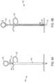
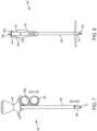
- FIGS. 1A-1Cillustrate one sheath inserter tool shown having a sheath coupled thereto.
- the sheath inserter tool 300generally includes a handle assembly 302 having a proximal end 300p with a proximal knob 303 and a distal end 300d with a distal actuator 304.
- the actuator 304is coupled to a proximal end of an outer shaft 306 that extends distally from the actuator 304.
- the knob 303is coupled to a proximal end of an inner shaft 310 that is slidably coupled to and extends proximally from the actuator 304.
- the inner shaft 310can include a distal end that mates to the actuator 304 such that the actuator 304 and outer shaft 306 are slidably movable relative to the inner shaft 310, but that prevents disengagement of the inner shaft 310 from the actuator 304 and outer shaft 306.
- the mating featurecan be in the form of a flange formed on a distal end of the inner shaft 310 and sized larger than an opening formed in a proximal end of the actuator 304 to prevent passage of the flange therethrough.
- the outer shaft 306can also include features at a distal end thereof for interacting with a sheath, as will be discussed below.
- the sheath inserter tool 300can include a locking mechanism for controlling movement of the inner and outer shafts 310, 306 relative to one another, as will be discussed in more detail below.
- the actuator 304can have a variety of configurations, but in the illustrated device, the actuator 304 on the outer component has a general T-shape configuration to facilitate grasping thereof.
- the actuator 304can have a blind bore extending therein from the distal end 300d and terminating just distal to the proximal-most end.
- the blind borecan be configured to receive a proximal end of the outer shaft 306 for mating the shaft to the actuator 304.
- the proximal end of the outer shaft 306may be fixedly and non-movably mated to the actuator 304, e.g., using adhesive, welding, a threaded engagement, or any other mating mechanism known in the art.
- the actuator 304can also include various features to facilitate grasping and actuation thereof. As shown, the actuator 304 extends laterally outward with respect to the shaft 306 and includes distal facing finger-gripping surfaces 340a, 340b. The proximal end 300p of the handle assembly 302 can be placed in a user's palm and the user's fingers can be positioned within the finger-gripping surfaces 340a, 340b to allow the user to pull the actuator 304 proximally with respect to the inner shaft 310 and knob 303. Since the actuator 304 is fixedly and non-movably mated to the outer shaft 306, movement of the actuator 304 relative to the knob 303 moves the outer shaft 306 relative to the inner shaft 310.
- the knob 303 of the handle assembly 302can also have a variety of configurations.
- the knob 303is generally cylindrical and is fixedly mated to a proximal end of the inner shaft 310.
- Various mating techniques, such as those described above,can be used to mate the two components.
- the outer shaft 306is coupled to and extends from the actuator 304 and can have a generally elongate cylindrical shape with a fork 308 on a distal end 300d thereof.
- the fork 308can function to both measure a tendon, and to facilitate insertion of the tendon and sheath 100 into a bone hole.
- the fork 308includes first and second elongate prongs 324a, 324b that are configured to extend longitudinally along opposed sides of the sheath 100 when the sheath is coupled to the distal end of the outer shaft 306.
- the elongate prongs 324a, 324bcan each have various shapes, such as a square or rectangular cross-sectional shape.
- the fork prongs 324a, 324bpreferably have a maximum width Wp that is sized to fit within a bone tunnel sized to receive the sheath.
- the outer shaft 306can also have an outer diameter D b that matches the maximum width Wp of the prongs, or the outer diameter D b of the outer shaft 306 can be greater than the maximum width Wp of the prongs to allow the distal end of the outer shaft 306 to act as a hard stop to limit an insertion depth of the prongs into a bone hole.
- the pair of prongs 324a, 324bcan extend distally beyond the distal end of the outer shaft 306 by a predetermined distance D to thereby define a u-shaped recess 322 between the pair of prongs 324a, 324b.
- the u-shaped recess 322can be configured to receive the sheath 100 therein, with the prongs 324a, 324b extending along the opposed sidewall cut-outs in the sheath 100.
- the handlecan include additional features for controlling movement of the inner and outer shafts 310, 306 relative to one another.
- the handle assembly 302includes a lock 314 disposed between the knob 303 and the actuator 304.
- the lockcan be mounted on the inner shaft 310 and it can be configured to rotate about its fixed point at the proximal end of the inner shaft 310.
- the lock 314extends along the entire length of the inner shaft 310 and extends between the knob 303 and the actuator 304, thereby preventing proximal movement of the actuator 304 and thus preventing the inner and outer shafts 310, 306 from moving longitudinally with respect to each other.
- the lock 314can be rotated 90 degrees to a perpendicular position, as shown in FIG. 1B . Since the lock 314 is no longer blocking movement of the actuator 304, the actuator 304 can be moved proximal from the position shown in FIG. 1B to the position shown in FIG. 1C .
- the sheathcan include a guidewire 140 mated thereto.
- the guidewire 140can extend from the sheath 100, proximally through the outer shaft 306, and through the inner shaft 310.
- the knob 303can include an internal feature for engaging the guidewire, such as threads formed therein for threadably mating to threads formed on a proximal end of the guidewire, or a compressible material that engages the guidewire by press-fit or any other technique known in the art.
- the knob 303With the guidewire being mated to the knob 303, the knob 303 will maintain the guidewire, and the sheath mated thereto, in a fixed position during proximal movement of the actuator 304 and outer shaft 306 relative to the knob 303 and inner shaft 310.
- the guidewiredoes not need to be engaged within the knob, alternatively the guidewire could be slid into the cannulation in the knob without being held by any engagement feature.
- the lock 314is preferably in the longitudinal position, as seen in FIG. 1A , during insertion of the tool and sheath through tissue, such that the lock 314 effectively blocks the actuator 304 and prevents any movement of the inner and outer shafts 310, 306 relative to one another.
- the sheath 100is loaded onto the distal end of the inserter and the fork 308 is in a fully extended position, extending distally beyond the sheath 100.
- the actuator 304may be moved proximally. Proximal movement of the actuator 304 will move the outer shaft 306 proximally, as shown in FIG. 1C .
- the fork 308, attached to the outer shaft 306,is thus moved proximally and withdrawn from the sheath 100.
- the tool 300can be removed leaving the sheath 100, with the guidewire attached thereto, implanted in the bone hole.
- a driver toolcan then be used to insert an expander, such as a screw, into the sheath to thereby anchor the sheath and a tendon positioned therearound, within the bone hole.
- the expandermay be delivered over the guidewire and into the sheath.
- each of the tools disclosed hereincan include a guidewire grasper that is configured to engage and releasably retain a guidewire in a fixed position with respect to the inner or outer components of the tool, i.e., the component that does not have the fork.
- each of the tools disclosed hereincan additionally or alternatively include a locking mechanism that is configured to lock the inner and outer components relative to one another, and the locking mechanism can have any of the various configurations disclosed herein.
- the toolscan also include other features, such as those disclosed in the above-referenced patent applications.
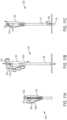
- FIGS. 2A-Bshow another sheath inserter tool 400 that is similar to the tool of FIGS. 1A-1B , but that includes a different handle assembly.
- the tool 400includes a handle 402 that is configured to releasably engage a guidewire 140 coupled to a sheath 100.
- An outer shaft 406slides within and extends distally from the handle 402.
- a proximal end of the outer shaft 406is disposed within the handle 402 and is coupled to an actuator 404.
- Both the actuator 404 and the outer shaft 406are slidably movable with respect to the handle 402 to thereby allow the outer shaft 406, with the fork on the distal end thereof, to be retracted relative to the sheath and guidewire.
- the fork on the distal end of the inserter toolis not described in detail, as it can have the same configuration as the fork described above with respect to FIGS. 1A-1C .
- the handle 402has a generally elongate cylindrical configuration to facilitate grasping thereof.
- the handle 402can have a blind bore extending therein from the distal end 402d and terminating just distal to the proximal-most end 400p.
- the borecan include a guidewire grasping element (not shown) for releasably engaging a guidewire.
- the grasping elementcan have a configuration as previously described with respect to FIGS. 1A-1C , or it can have a configuration as described in the aforementioned patent applications.
- a distal portion of the borecan slidably receive the proximal end of the outer shaft 406.
- the handle 402can further include elongate longitudinal cut-outs 438a, 438b formed in opposite sidewalls thereof and in communication with the bore. The cut-outs 438a, 438b can allow the actuator 404 to extend therethrough and to slidably move there along.
- the actuator 404is similar to the actuator of FIGS. 1A-1C and is generally T-shaped with distal facing finger-gripping surfaces 440a, 440b.
- the actuator 404extends laterally outward from opposed sides of the handle 402, and thus allows a user to place the proximal end 400p of the handle 402 in their palm and to grasp the actuator 404 with one or more fingers to pull the actuator 404 proximally.
- the actuatorcan thus slide proximally and distally relative to the handle.
- the actuator 404can be fixedly mated to or integrally formed on the proximal end of the outer shaft 406. As a result, movement of the actuator 404 relative to the handle 402 moves the outer shaft 406 relative to the handle 402 (once the lock 414 is released). While not shown, a person skilled in the art will appreciate that the guidewire extends through a lumen in the outer shaft, through a lumen in the actuator, and through the bore in the handle.
- the handlecan include additional features for controlling movement of the outer shaft 406 relative to the handle 402.
- the handle 402includes a lock 414 disposed thereon.
- the lock 414can be actuated by pressing the lock 414 into the handle 402.
- the lock 414blocks proximal movement of the actuator 404 and thus locks the outer shaft 406 in a fixed position relative to the handle 402.
- the lock 414In order to move the actuator 404 and the outer shaft 406 proximally relative to the handle 402 (thereby retracting the fork 408 relative to the guidewire and the sheath 100), the lock 414 must be moved to an unlocked position, shown in FIG.
- Movement of the lock between the locked and unlocked positionscan be achieved using, for example, a push-button mechanism having a rotating component that alternates between two positions, the locked and unlocked position.
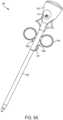
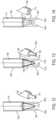
- FIGS. 3A-3Cshow another sheath inserter tool 500 that is similar to the tool of FIGS. 2A -2C, but that has a pistol-grip handle assembly.
- the tool 500generally includes a handle 502, an actuator 504 slidably disposed within and extending through the handle 502, and an outer shaft 506 coupled to the actuator 504 and extending within and distally from the handle 502.
- the outer shaft 506can include the fork on the distal end thereof, as previously described above with respect to FIGS. 1A-1C .
- the handle 502has a generally elongate cylindrical configuration with a pistol-grip portion to facilitate grasping thereof.
- the handle 502can have a blind bore extending therein from the distal end 502d and terminating just distal to the proximal-most end.
- the borecan be configured to receive the guidewire mated to the sheath, as shown, and a distal portion of the bore can receive the proximal end of the outer shaft 506 for mating the shaft to the actuator.
- the handle 502can further include an elongate longitudinal cut-out 538a formed in a sidewall thereof and in communication with the inner lumen. The cut-out 538a can allow the actuator 504 on the inner component to extend therethrough and to slidably move there along.
- the actuator 504is generally trigger-shaped and includes a distal facing finger-gripping surface 540a.
- the actuator 504extends laterally outward from a side of the handle 502, and thus allows a user to place the pistol-grip portion of the handle 502 in their palm and to grasp the actuator 504 with one or two fingers to pull the actuator 504 proximally towards the pistol-grip portion of the handle 502.
- the actuatorcan thus slide proximally and distally relative to the handle.
- the actuator 504can be fixedly mated to or integrally formed on the proximal end of the outer shaft 506. As a result, after the lock 514 is released, movement of the actuator 504 relative to the handle 502 moves the outer shaft 506 relative to the handle 502 and to the guidewire coupled to the sheath 100.
- the handle 502includes a lock 514 disposed thereon that is similar to the lock 414 of FIGS. 2A -2C.
- the lock 514can be moved into a locked position by pushing the lock 514 into the handle 502.
- the lock 514prevents proximal movement of the actuator 504 and locks the outer shaft 506 from moving longitudinally with respect to the handle 502.
- the lock 514In order to move the actuator 504 and the outer shaft 506 proximally relative to the handle 502 and the guidewire, the lock 514 must be moved to an unlocked position. This can be achieved by pressing the lock 514 so that it moves out and no longer blocks movement of the actuator 504. Proximal movement of the actuator 504 will retract the fork 508 from the sheath 100, as shown in FIG. 3C .
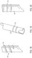
- FIGS. 4A-4Bshow an embodiment of a sheath inserter tool 600.
- the tool 600includes an inner component having the fork thereon, and the inner component is moved proximally relative to an outer component and the guidewire.
- the tool 600includes an outer component having a handle 602 with an outer shaft 606 extending distally therefrom, and an inner component that includes an actuator 604 in the form of a finger loop that is coupled to a proximal end of an inner shaft 610 that extends through the handle 602 the outer shaft 606.
- Movement of the inner shaft relative to the outer shaftis effective to move the fork between an extended position, in which the fork extends beyond a distal end of the outer shaft, and a retracted position, in which the fork is retracted into the outer shaft.
- the handle 602 in this embodimenthas a generally T-shaped configuration with one side being in the form of a finger loop and the other side being in the form of a half-loop having a generally elongated arced shaped.
- This configurationallows a user to rest one finger, e.g., their pointer finger, against the half-loop, and to insert another finger, e.g., their middle finger, through the finger loop.
- the finger loop and half-loop that form the handle 602can be integrally formed on or fixedly mated to a proximal end of the outer shaft 602. Both the outer shaft and the handle 602 can include a central lumen extending therethrough for slidably receiving the inner shaft 610.
- the actuator 604which is positioned proximal to the handle 602 and which is coupled to the inner shaft 610, is generally loop-shaped and is configured to receive, for example, a user's thumb.
- the actuator 604can be fixedly mated to or integrally formed on the proximal end of the inner shaft 610. As a result, movement of the actuator 604 relative to the handle 602 moves the inner shaft 610 relative to the outer shaft 606.
- the tool 600can also include a lock 614 for locking the inner and outer shafts 610, 606 in a fixed position relative to one another.
- the lock 614can be in the form of a removable structure that can be snapped onto the inner shaft 610 and that can also engage a flange or other feature (not shown) formed on a proximal end of the handle 602. When the lock 614 is mated to the inner shaft 610 and the handle 602, the inner and outer shafts 610, 606 are prevented from longitudinal movement.
- the devicecan be inserted through tissue or through a cannula in the locked position, and once the sheath is implanted within a bone hole, the lock 614 can be removed by moving the lock 614 laterally away from the device 600. With the lock removed, as shown in FIG. 4B , the actuator 604 and the inner shaft 610 can be moved proximally away from the handle 602 and outer shaft 610, thereby retracting the fork 608 out of the sheath 100 and into the outer shaft 606. The outer shaft 606 can remain in position, pressing the sheath into the bone hole.
- FIGS. 5A-Bshow another embodiment of a sheath inserter tool 700 that functions in a similar manner to the tool of FIGS. 4A-4B , but that includes a different handle assembly.
- the tool 700includes an outer component having a handle 702 with an outer shaft 706 extending therefrom, and an inner component that includes an actuator 704 that is slidably coupled to an inner shaft 710 extending from the actuator 704 and through the handle 702 and the outer shaft 706.
- the handle 702has a generally elongate cylindrical configuration to facilitate grasping thereof.
- the diametercan remain constant along the length of the handle 702, or a proximal or the handle can taper inward in a proximal direction, and a distal portion of the handle can taper inward in a distal direction, as shown.
- the handle 702can have a bore extending entirely therethrough.
- the borecan be configured to slidably receive the inner shaft therethrough, and a distal portion of the bore can receive the proximal end of the outer shaft 706 for mating the outer shaft to the handle.
- Various mating techniques as described abovecan be used to fixedly mate the outer shaft 706 to the handle 702.
- the actuator 704 in this embodimenthas a conical shape that tapers inward in a distal direction to form a distal facing finger-gripping surface 740a.
- the actuator 704is positioned proximal of the handle 702 to thus allow a user to wrap their fingers around the handle, as indicated by the circles, and to place their thumb in the finger-gripping surface 740a to push the actuator 704 proximally upwards away from the handle 702.
- the actuatorcan thus slide proximally and distally relative to the handle 702.
- the actuator 704can be fixedly mated to or integrally formed on the proximal end of the inner shaft 710. As a result, movement of the actuator 704 relative to the handle 702 moves the inner shaft 710 relative to the outer shaft 706.
- the device 700further includes a lock 714 disposed on the inner shaft 710 and configured to engage the proximal portion of the handle 702.
- the handle 702can include a flange or other feature that is engaged by the lock 714 so as to allow the lock 714 to prevent movement of the inner shaft 710 and the handle relative to one another.
- the lock 714can alternatively engage the actuator 704, rather than the inner shaft 710, to prevent movement of the inner and outer components relative to one another.
- the lock 714prevents proximal movement of the actuator 704 and locks the inner and outer shafts 710, 706 from moving longitudinally with respect to each other.
- the lock 714can be removed from the device, as can be seen in FIG. 5B .
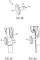
- FIGS. 6A and 7show two additional embodiments of sheath inserter tools 800, 800', each of which includes an outer component having a handle 802, 802' with an outer shaft 806, 806' extending distally therefrom, and an inner component that includes an actuator 804, 804' that is positioned distal of the handle 802, 802' and that is mated to or integrally formed on the inner shaft 810, 810'.
- the actuator 804, 804'can extend through longitudinal slots in the outer shaft 806, 806', and the inner shaft 810 can be slidably disposed within the outer shaft 806, 806'. While not described in detail, a person skilled in the art will appreciate that the tools of FIGS. 6 and 7 can function as previously described with respect to FIGS. 4A-4B .
- Each handle 802, 802'can have a generally conical, knob-like configuration for allowing the handle to sit within a user's palm.
- the handles 802, 802'can include distal-facing recesses formed therein that are configured to seat the finger loop or loops on the actuator, as will be discussed below.
- Each handle 802, 802'can also have a blind bore extending therein from the distal end and terminating at a location distal to the proximal-most end.
- the borecan be configured to receive and releasably mate to a guidewire, as described above with respect to FIGS. 1A-1C .
- a distal portion of the borecan receive the proximal end of the outer shaft 806 for mating the shaft to the handle.
- the outer shaft 806can further include two elongate longitudinal cut-outs 838a, 838b, as shown in FIG. 6A , or only a single cut-out 838a' as shown in FIG. 7 , formed in the sidewall thereof and in communication with the inner lumen.
- the cut-outs 838a, 838b, 838a'can allow the actuator 804 on the inner component to extend therethrough and to slidably move there along.
- the actuator 804 in FIG. 6Ahas first and second finger loops for receiving a user's fingers, e.g., the pointer and middle fingers.
- the actuator 804' in FIG. 7only has a single finger loop for receiving a single finger, e.g., a pointer finger or thumb.
- Each actuator 804, 804'extends laterally outward from a sidewall of the outer shaft 806, 806', and thus allows a user to place the proximal end of the handle 802, 802' in their palm and to grasp the actuator 804, 804' with one or more fingers to pull the actuator 804, 804' proximally.
- the actuatorcan thus slide proximally and distally relative to the handle.
- the actuator 804, 804'can be fixedly mated to or integrally formed on a proximal portion of the inner shaft 810, 810'.
- the inner shaft 810 810'extends proximally beyond the actuator to allow the proximal end of the inner shaft to extend into the handle 802 and to be engaged by the lock 814, discussed below.
- movement of the actuator 804, 804' relative to the handle 802, 802'moves the inner shaft 810, 810' relative to the outer shaft 806, 806' and relative to a guidewire coupled to the handle 802, 802'.
- Each toolcan further include a lock 814 extending through the handle 802, as seen in FIG. 6A . While only FIG. 6A illustrates a lock, a person skilled in the art will appreciate that the tool of FIG. 7 can likewise include a lock.
- the lock 814is shown in more detail in FIGS. 6B-6D , and is generally in the form of an elongate member having a central opening or elongate cut-out 814c formed therein. As shown in FIG. 6B , the cut-out 814c can include an engagement feature 814e, such as a protrusion or ledge, that is configured to be moved in and out of one or more grooves formed in the proximal end of the inner shaft 810.
- one end of the lock 814can include a bump 814a formed therein and the other end of the lock 814 can include a recess 814b formed therein.
- the engagement feature 814ecan be formed within the cut-out 814c at a location adjacent to the bump 814a, such that the bump 814a can indicate the closed positioned, whereas the recess 814b can indicate the open position, as will be discussed in more detail below.
- the proximal end of the inner shaft 810can include three grooves 815a, 815b, 815c formed therein and spaced longitudinally there along.
- the proximal-most groove 815acan correspond to a position in which the inner shaft 810 is fully extended relative to the outer shaft 806, the distal-most groove 815c can correspond to a position in which the inner shaft 810 is fully retracted relative to the outer shaft 806, and the middle groove 815b can correspond to a mid-position between the fully extended and fully retracted positions.
- the inner shaft 810can include any number of grooves formed therein as may be desired.
- FIG. 6Cillustrates the lock 814 engaged in the middle position with the middle groove 815b, with the bump 814a positioned closer to the inner shaft 810 than the recess 814b. The inner shaft 810 is thus preventing from moving relative to the outer shaft 806. Pressing on the recess 814b to slide the lock 814 relative to the handle 802 will move the engagement feature 814e out of engagement with the groove 815b, thus allowing free slidable movement of the inner shaft 810 relative to the outer shaft 806.
- the inner shaftcan also include features that resist movement of the inner shaft relative to the outer shaft when the lock 814 is disengaged. Such features can also include the position of the inner shaft relative to the proximal-most, middle, and distal-most positions as defined by the grooves 815a-c.
- a collar 816is disposed around the proximal end of the inner shaft 806 and it includes opposed elongate slots 817, 819 formed therein. While only slot 817 is discussed, it will be appreciated that slot 819 can include the same features and can function in the same manner.
- slot 817can include a three notches formed therein, a proximal-most notch 817p, a middle notch 817m, and a distal notch 817d.
- Each notch 817p, 817m, 817dcan be configured to frictionally engage a pin 810p formed on or coupled to the proximal end of the inner shaft 810, at a location above the grooves 815a-c. The notches can engage the pin to hinder but not prevent movement.
- each notch 817p, 817m, 817dcan be positioned such that, when the pin 810p is seated therein, the button 814 will be aligned with the corresponding proximal, middle, or distal grooves 815a-c.
- the collar 816can include side slots 821a, 821b formed on opposed sides thereof.
- the side slots 821a, 821ballow the sidewalls surrounding slot 817 to flex as the pin 810p is moved into a notch 817p, 817m, 817d.
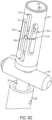
- FIGS. 6E-6Gillustrate a button 842 that is configured to releasably engage the guidewire G extending through the shaft 806.
- the buttonincludes a head 842h and shaft 842s extending therefrom.
- the shaft 842sincludes a slot or cut-out 842c formed in the distal end thereof for engaging the guidewire G.
- the cut-out 842cis configured to snap onto the guidewire G to prevent movement of the guidewire G relative to the button 842.
- the outer shaft 806can include an opening 842a formed therein for receiving the button 842. In use, the button 842 can be pressed through the opening 842a to cause the cut-out 842c to engage the guidewire G, and removing the button can release the guidewire G.
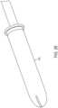
- FIG. 8shows another embodiment of a sheath inserter tool 900 that functions in a similar manner as described above.
- the toolincludes an outer component having a handle 902 with an outer shaft 906 extending therefrom, and an inner component that includes an actuator 904 that is coupled to the inner shaft 910, which extends through the handle 902 and the outer shaft 906.
- the handle 902has a generally elongate cylindrical configuration to facilitate grasping thereof.
- the handle 902can have a bore extending entirely therethrough.
- the borecan be configured to slidably receive the inner shaft therethrough, and a distal portion of the bore can receive the proximal end of the outer shaft 906 for mating the shaft to the handle.
- the handle 902can further include a side cut-out 938a formed in a sidewall thereof and a top cut-out or opening 938b formed in the proximal-most end thereof.
- the side cut-out 938acan allow a lateral finger grip 940a to extend therethrough, and the top cut-out 938b can allow a proximal finger grip 940b to extend therethrough.
- the actuator 904is generally conical and includes a biasing element 905 (such as a spring) proximal to the inner shaft 910 in the handle 902 that, in a compressed state, results in the fork 908 being in a fully extended position when the sheath 100 is mated to the tool (as shown in FIG. 8 ).
- the actuator 904can be actuated by pressing the lateral finger grip 940a radially inward toward the handle 902 until the surface 940a is within the handle. This radially inward movement causes the biasing element 905 to be released from the compressed state.
- the release of the biasing element 905will cause the biasing element 905 to move proximally to an elongated, relaxed state, which will cause the inner shaft 910 to move proximally with respect to the outer shaft 906 and handle 902, thereby retracting the fork 908 from the sheath 100 and into the outer shaft.
- the movementwill cause the proximal finger grip 940b to move proximally relative to the handle 902.
- Distal movement of the proximal finger grip 940bcan reverse the retraction, causing the biasing element 905 to re-compress by moving the spring distally into a compressed state until the lateral finger grip 940a can again extend through the cut-out 938a.
- This movementwill cause the inner shaft 910 to move distally again.
- a usercan place the elongate cylindrical configuration of the handle 902 in their palm and manipulate the actuator 904 with, for example, a thumb.
- the actuator 904can be fixedly mated to or integrally formed on the proximal end of the inner shaft 910. As a result, movement of the actuator 904 relative to the handle 902 moves the inner shaft 910 relative to the outer shaft 906.
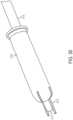
- FIG. 9shows a proximal portion of another embodiment of a sheath inserter tool 1000 that can function as previously described with respect to FIGS. 4A-4B .
- the tool 1000includes an outer component having a handle 1002 with an outer shaft 1006 extending therefrom, and an inner component that includes an actuator 1004 that is slidably disposed relative to the handle 1002 and that is coupled to an inner shaft 1010 extending through the handle and through the outer shaft 1006.
- the distal endcan be similar to the aforementioned embodiments, with the inner shaft including a fork thereon as described with respect to FIGS. 1A-1C .
- the handle 1002has a generally elongate cylindrical configuration to facilitate grasping thereof.
- the handle 1002can have a blind bore extending therethrough from the distal end 1002d and terminating just distal to the proximal-most end.
- the borecan be configured to receive a proximal end of a guidewire mated to a sheath. While not shown, the bore can include a guidewire grasper for releasably engaging the guidewire, as discussed above.
- a distal portion of the borecan receive the proximal end of the outer shaft 1006 for mating the shaft to the handle.
- the handle 1002can further include an elongate longitudinal cut-out 1038a formed in a sidewall thereof and in communication with the inner lumen. The cut-out 1038a can allow the actuator 1004 on the inner component to extend therethrough and to slidably move there along.
- the actuator 1004is in the form of a sliding button or knob that includes a finger-gripping surface 1040a.
- the actuator 1004extends laterally outward from a side of the handle 1002, and thus allows a user to place the handle 1002 in their palm and to manipulate the actuator 1004 with fingers, for example a thumb, to move the actuator 1004 proximally and distally relative to the handle.
- the actuator 1004can be fixedly mated to or integrally formed on the proximal end of the inner shaft 1010.
- the handle 1002can also include a lock (not shown).
- FIGS. 10A-10Bshow another sheath inserter tool 1100 that functions in a similar manner to the aforementioned embodiments, and that generally includes an outer component having a handle 1102 with an outer shaft 1106 extending therefrom, and an inner component that includes an actuator 1104 that is positioned proximal to the handle 1102 and that is coupled to a proximal end of an inner shaft 1110 extending through the handle 1102 and through the outer shaft 1106.
- the handle 1102has a generally elongate cylindrical configuration to facilitate grasping thereof.
- the handle 1102can have a bore extending entirely therethrough for receiving the inner shaft.
- a distal portion of the borecan receive the proximal end of the outer shaft 1106 for mating the shaft to the handle.
- the borecan allow the actuator 1104, or a portion thereof, on the inner component to extend therethrough and to rotatably move thereabove.
- the actuator 1104is generally disc-shaped and includes a finger-gripping surface 1140a.
- the actuator 1104is positioned at a proximal end of the handle 1102, and thus allows a user to place the elongate cylindrical configuration of the handle 1102 in their palm and to manipulate the actuator 1104 with, for example, a thumb to rotate the actuator 1104 relative to the handle 1102.
- the actuator 1104can be threadably mated to the proximal end of the inner shaft 1110.
- the actuator 1104can include a cylindrical shaft extending longitudinally from the disc-shaped portion and having threads formed therein that are configured to mate with threads on a proximal end of the inner shaft.
- the actuator 1104can be coupled to the handle 1102 such that it is freely rotatable, but is prevented from moving axially. As a result, rotation of the actuator 1104 relative to the handle 1102 moves the inner shaft 1110 relative to the outer shaft 1106. Rotation of the actuator 1104 can thus cause proximal movement of the inner shaft 1110 relative to the handle 1102 and outer shaft 1110 to thereby retract a fork on the inner shaft from a sheath and into the outer shaft.
- the handle 1102can also include a lock (not shown). The lock can be incorporated into the actuator 1104, for example by using ball and detents that retain the actuator 1104 in one or more positions.
- FIGS. 11A-11Cshow another embodiment of a sheath inserter tool 1200 having an outer component with a handle 1202 with an outer shaft 1206 extending distally therefrom, and an inner component that includes an actuator 1204 that is pivotably coupled to the handle 1202 and that is coupled to an inner shaft 1210 extending through the outer shaft 1206.
- the toolfunctions in a similar manner as described above with respect to FIGS. 4A-4B , with the inner shaft having a fork on a distal end thereof that is movable between extended and retracted positions.
- the handle 1202 in this embodimenthas a generally elongate cylindrical configuration to facilitate grasping thereof.
- the handle 1202can have a blind bore extending therethrough from the distal end 1202d and terminating just distal to the proximal-most end.
- the borecan be configured to receive a guidewire coupled to the sheath, and it can optionally include components for releasably engaging the guidewire.
- a distal portion of the borecan receive the proximal end of the outer shaft 1206 for mating the shaft to the handle.
- the actuator 1204 in this embodimentis generally lever-shaped and includes finger-gripping surface 1240a.
- the actuator 1204is pivotably attached to the handle 1202 and extends laterally outward in a resting position from a side of the handle 1202, as shown in FIG. 11A . This allows a user to place the handle 1202 in their palm and to manipulate the actuator 1204 with their fingers (as indicated by the circles) to squeeze and pivotally move the actuator 1204 toward the handle 1202.
- a linkage 1207extends from a proximal end of the actuator 1204 and is coupled to a distal end of a biasing element, e.g., a spring 1209 located inside the handle 1202. The spring is positioned proximal to the inner shaft 1210 and is coupled to the inner shaft 1210.
- the biasing element of the actuator 1204causes the fork 1208 on the inner shaft to be in a fully extended position, extending from the outer shaft 1206.
- the linkageupon pivotal movement of the actuator 1204 relative to the handle 1202, the linkage causes the spring to compress proximally, thereby moving the inner shaft proximally relative to the outer shaft 1206 to retract the fork 1208 into the outer shaft.
- the handle 1202can also include a lock (not shown) which can be separate from or incorporated into the actuator 1204.
- tools discussed abovecan have a variety of configurations.
- the handlecan be integrally formed on the outer shaft or the outer shaft can be mated to a distal facing surface of the handle without the need to extend into the handle.
- Other similar modificationscan be made as needed to connect the various components.
- FIGS. 12-14show a sheath alignment feature a that can be included in an inserter tool, including any of the inserter tools discussed above.
- FIG. 12shows an outer shaft 1306 and inner shaft 1310.
- a fork 1308is formed on or mated to the distal end of the inner shaft 1310, and the fork 1308 includes first and second elongate prongs 1324a, 1324b extending longitudinally from opposed sides of the inner shaft 1310.
- the outer shaft 1306includes a sheath alignment feature 1312 formed on a distal end thereof and having a generally cone-shaped configuration, tapering inward in a distal direction.
- the shapecan be configured to match the shape of an inner lumen or bore in a sheath so as to allow the sheath alignment feature to be received within the sheath when the sheath is mated to the inserter tool.
- the sheath alignment feature 1312can further include cut-outs or openings formed in opposed sides adjacent to the proximal end for receiving the prongs therethrough.
- the sheath alignment feature 1312can have a proximal portion having a diameter that is smaller than the diameter of the distal end of inner shaft.
- first and second elongate prongs 1324a, 1324b on the inner shaft 1310can extend through the cut-outs in the sheath alignment feature (or the distal end of the outer shaft) and to extend along opposed sides of the sheath alignment feature 1312.
- the sheath alignment featurecan extend into a sheath coupled to the tool, thereby facilitating alignment of the sheath with respect to the tool.
- the prongscan extend along the sheath alignment feature and along opposed sidewalls slots in the sheath.
- FIG. 13shows another embodiment of a sheath alignment feature 1362 that is similar to the feature of FIG. 14 , but that includes elongate cut-outs formed in opposed sides of the sheath alignment feature 1362.
- the inner shaft 1360includes a fork 1358 first and second elongate prongs 1374a, 1374b that extend longitudinally along opposed sides of the sheath alignment feature 1362 on the outer shaft 1360.
- the sheath alignment featureincludes first and second opposed cut-outs 1375a, 1375b formed therein and configured to receive the first and second elongate prongs 1374a, 1374b.
- FIG. 14shows another a distal portion of an insertion tool that is similar to the embodiments of FIGS. 12 and 13 , but that includes an elongate slot in the outer shaft 1406 for receiving the forks on the inner shaft 1410.
- the distal end of the outer shaft 1406is closed with an elongate slot 1416 formed therein.
- the elongate slotis dimensioned and configured for receiving first and second prongs 1424a, 1424b of fork 1408 such that the first and second prongs 1424a, 1424b can extend distally from the distal end of inner shaft 1410, as with other embodiments.
- a sheath alignment feature 1412is formed on the fork 1408 between the first and second prongs 1424a, 1424b.
- the illustrated sheath alignment feature 1412has a generally cone-shaped configuration, tapering inward in a distal direction.
- FIGS. 15-20illustrate various tools for maintaining tension on a tendon during anchoring of the tendon. These features can be incorporated into an inserter tool, including any of the inserter tools discussed above, or they can be provided on a separate tool, such as a cannula.
- FIGS. 15-17illustrate a tool, in the form of a cannula that includes an outer shaft 1502 having a distal end 1502d with a saddled or beveled edge 1506 forming an angled viewing window.
- the beveled edge 1506can be rounded and can extend cross-sectionally through the shaft 1502 from a first sidewall 1510 to a second sidewall 1512 on the opposite side of the shaft 1502, such that the first sidewall 1510 extends a distance distally beyond the second sidewall 1512.
- Such a configurationwill result in an opening through the second sidewall 1512 when the cannula 1500 is positioned against tissue and bone, as shown in FIG. 17 .
- a forked inserter tool 1514can be passed through the outer shaft 1502 to allow prongs 1518a, 1518b on the forked distal end 1516 to be used to advance a tendon into a bone hole.
- the forked inserter tool 1514can move axially relative to the outer shaft 1502 to retract and extend the prongs 1518a, 1518b into and from the outer shaft 1502.
- the distal-most end of the outer shaft 1502can be positioned on a tendon T against bone B to pinch the tendon T to be anchored and thereby prevent slippage of the tendon T.
- the outer shaft 1502is preferably positioned on a side of the bone hole H that the tendon extends from, e.g., the distal side of a bone hole on the humerus for a biceps tenodesis procedure.
- the outer shaftwill thus maintain a tension of the tendon T, while the forked inserter tool is extended to push or dunk the tendon into the bone hole.
- the forkcan have a sheath loaded thereon that is inserted into the bone hole to maintain the tendon in the bone hole.
- the cannula or outer shaft of an inserter toolcan include various features formed thereon to resist backout or any unintentional proximal movement of the outer shaft during use.
- FIG. 18illustrates threads 1522 formed on an outer shaft 1520
- FIGS. 19 and 20illustrate ribs 1532 formed on the outer shaft 1530.
- the threads and ribscan provide resistance against the surrounding tissue to resist any unintentional proximal movement of the outer shaft.
- the distal portion of the outer shaftcan be free of surface features.
- the distal portion of the outer shaftcan be formed from a transparent material, can include a compressible material, and/or can have smooth surface.
- a sheath insertercan include a distal end having movable tendon engagement features.
- an inserter tool 1600is provided and includes an outer shaft 1602 coupled to a handle as discussed above and an inner shaft 1604 having a tendon engagement member 1606.
- the tendon engagement member 1606can be in the form of a pivotable arm having a proximal end that is coupled to the inner shaft 1604 via a hinge 1610 or similar attachment mechanism.
- the distal end of the tendon engagement member 1606dcan move laterally away from and rotate about the axis of the hinge.
- the distal end of the inner shaft 1604dcan be inserted into an anchor 1620.
- the anchor 1620can have an inner lumen 1624 to receive the distal end of the inner shaft 1604d, ribs 1622 formed thereon and a recess feature 1626 to receive the tendon engagement feature. As shown in FIG. 22 , when the anchor 1620 is coupled to the inserter 1600 the proximal end of the anchor 1620p abuts the distal end of the outer shaft 1602d. The distal end of the inner shaft 1604d can extend through the inner lumen 1624 and past the distal end of the anchor 1620d.
- the tendon engagement feature 1606can be advanced and articulated to grab the tendon and pull the tendon proximate to the anchor 1620. The inserter 1600 can then be advanced to position the tendon and the anchor 1620 inside the bone hole.
- the tension on the tendonis thus maintained by the inserter tool during insertion of the tendon into the bone hole.
- the anchor 1620is illustrated with threads formed thereon, the anchor can be non-threaded or can include along only portions or the entire length thereof.
- FIGS. 23-31illustrate various a sheath/fork protectors that are configured to cover a sheath/fork and optionally a distal portion of a sheath inserter tool during insertion through tissue, and/or that facilitates insertion of the device through tissue.
- FIG. 23shows a disposable, thin-walled sheath protector 2105 that effectively covers a sheath 2106, a fork with prongs 2107, and a distal end of an inserter 2108.
- the sheath protector 2105has a generally elongate cylindrical configuration with a conical distal tip.
- the conical distal tipcan function as an obturator to facilitate penetration through tissue percutaneously.
- the length of the sheath protectorcan be configured to allow the sheath protector 2105 to extend over a portion of the distal end of the outer shaft.
- a proximal end of the sheath protector 2105can include a tab extending radially outward therefrom to facilitate grasping of the sheath protector.
- the sheath protectoris inserted through tissue in the position shown in FIG. 23 .
- the tab on the proximal endcan then be grasped and the sheath protector can be slid proximally along the outer shaft to expose the sheath and the distal end of the inserter tool once inserted.
- the distal conical portion of the sheath protectorcan include one or more slits formed therein to allow the distal end to open up and expand around the sheath and outer shaft.
- FIGS. 24-25show another sheath protector 2121 with an angled distal tip 2121d, which can assist in accurate insertion in procedures when narrow or small insertion points are required.
- FIG. 26shows another sheath protector 2130 which has a semi-cylindrical shape and is open along its entire longitudinal length. The sheath protector can be inserted through tissue to provide a pathway or slide for insertion of the sheath/fork. The fork 2131 and sheath 2132 can be introduced by sliding them along the open sheath protector 2130.
- FIG. 27shows another a bullet-shaped sheath/fork protector 2140.
- FIG. 28shows two sheath/fork protectors 2150, 2151 having different sizes for use with different sized sheaths
- FIG. 29shows a sheath protector 2160 covering a distal end of an inserter with a sheath.
- the sheath protectorscan be configured with distal tips designed to separate (open and close) upon distal movement of the inserter and sheath.
- FIGS. 30 and 31the sheath 2171 and the inserter 2172 with a fork 2173 can be advanced through the distal end of the sheath protector 2170 for allowing plunging of the sheath into a bone hole.
- FIG. 31shows the sheath 2171 and the sheath inserter 2172 including the fork and the shaft extending beyond the distal tip of the sheath protector 2170.
- the distal tip 2170d of the sheath protector 2170can be configured to assist the distal penetration of the sheath 2171 and inserter 2172 with fork 2173 through skin.
- the sheath protector 2170can be designed with slits to allow the distal tip 2170d to remain closed during insertion thus preventing the forks or sheath from catching on tissue, and once inserted through tissue to flare open upon distal movement.
- the devices disclosed hereincan be designed to be disposed of after a single use, or they can be designed to be used multiple times. In either case, however, the device can be reconditioned for reuse after at least one use. Reconditioning can include any combination of the steps of disassembly of the device, followed by cleaning or replacement of particular pieces, and subsequent reassembly. In particular, the device can be disassembled, and any number of the particular pieces or parts of the device can be selectively replaced or removed in any combination. Upon cleaning and/or replacement of particular parts, the device can be reassembled for subsequent use either at a reconditioning facility, or by a surgical team immediately prior to a surgical procedure.
- reconditioning of a devicecan utilize a variety of techniques for disassembly, cleaning/replacement, and reassembly. Use of such techniques, and the resulting reconditioned device, are all within the scope of the present application.
- the invention described hereinwill be processed before surgery.
- a new or used instrumentis obtained and if necessary cleaned.
- the instrumentcan then be sterilized.
- the instrumentis placed in a closed and sealed container, such as a plastic or TYVEK bag.
- the container and instrumentare then placed in a field of radiation that can penetrate the container, such as gamma radiation, x-rays, or high-energy electrons.
- the radiationkills bacteria on the instrument and in the container.
- the sterilized instrumentcan then be stored in the sterile container.
- the sealed containerkeeps the instrument sterile until it is opened in the medical facility.
- deviceis sterilized. This can be done by any number of ways known to those skilled in the art including beta or gamma radiation, ethylene oxide, steam.
Landscapes
- Health & Medical Sciences (AREA)
- Life Sciences & Earth Sciences (AREA)
- Orthopedic Medicine & Surgery (AREA)
- Animal Behavior & Ethology (AREA)
- Veterinary Medicine (AREA)
- Public Health (AREA)
- Engineering & Computer Science (AREA)
- Biomedical Technology (AREA)
- Heart & Thoracic Surgery (AREA)
- General Health & Medical Sciences (AREA)
- Surgery (AREA)
- Rheumatology (AREA)
- Oral & Maxillofacial Surgery (AREA)
- Vascular Medicine (AREA)
- Transplantation (AREA)
- Cardiology (AREA)
- Rehabilitation Therapy (AREA)
- Nuclear Medicine, Radiotherapy & Molecular Imaging (AREA)
- Medical Informatics (AREA)
- Molecular Biology (AREA)
- Surgical Instruments (AREA)
Description
- Surgical devices are provided for anchoring tissue to bone, and more particularly surgical implants and delivery tools are provided for securing a biceps tendon to the humerus.
- Disorders of the long head of the biceps tendon are a common source of shoulder pain and may occur in association with other diagnoses such as rotator cuff tears, superior labrum anterior posterior tears, impingement syndrome and capsular injuries, or may be present as an isolated source of shoulder pain. The treatment options for disorders of the long head of the biceps (LHB) continue to evolve and can include LHB tenodesis. In a tenodesis procedure, a suture is passed through the base of the LHB to locate the LHB in the subacromial space and to provide proximal control during the dissection. Once the suture is placed, the LHB is cut near the glenoid attachment. A sizer can be used to measure the tendon size and to thereby determine the appropriately sized bone screw. Once the screw is selected, a bone hole is drilled and a tendon fork is then used to push the tendon down into the bone hole. A bone screw is then delivered into the bone hole to anchor the tendon within the bone hole.
- While current procedures can provide an effective means for anchoring a tendon to bone, they can suffer from several drawbacks. For example, current procedures require the use of numerous tools, which can lead to a prolonged procedure and increased costs. The use of a screw can also increase the risk of damage to the tendon, as rotation of the screw into the bone hole can tear through the tendon. Moreover, it can be difficult to maintain the desired tension on the tendon while the screw is being implanted, as the tendon can slip during insertion of the screw. Any tension applied to the tendon during insertion of the anchor can also cause the anchor to back-out of the bone hole.
- Accordingly, there remains a need for improved devices for anchoring tissue to bone, and in particular for performing a biceps tenodesis.
US2004/193217 describes an apparatus for tendon or ligament repair that uses an anchor that is screwed into bone. A tool for installing a soft tissue anchor into a tendon or ligament and driving a needle and elongate tensile member into the tendon or ligament includes an elongate tubular housing having a first end and a second end. The first end of the housing receives a soft tissue anchor and a handle is provided at the second end. A tubular shaft within the housing is coupled with a first knob 218 provided on the handle at the end opposite the housing. A shaft extends through the housing to the first end and is coupled to a drive head having a projecting portion near the first end of the housing. The projecting portion engages a drive on the soft tissue anchor and the first knob is manipulated to rotate the shaft while advancing the shaft to extend beyond the first end of the housing. Accordingly, the soft tissue anchor received in the first end of the housing is driven into a tendon or ligament by the drive head when the first knob is manipulated.US2010/106194 describes an instrument that is used to secure a bushing to a cable. Each of first and second arms of a collett includes force application end portions. The force application end portions combine to form a bushing aperture and receive the bushing therein. The collett is made of a semi-rigid material, such that the first and second collett arms can be moved from an open to a closed position, closing the gap between the force application end portions.- Various implants and tools are provided for attaching a biceps tendon to a bone.
- The present invention provides a tendon anchoring system as recited in claim 1. Optional features are recited in the dependent claims.
- The handle assembly can include a locking mechanism that is movable between a locked position, in which the locking mechanism prevents movement of the first and second elongate bodies relative to one another, and an unlocked position in which the first and second elongate bodies are axially slidable relative to one another.
- The invention will be more fully understood from the following detailed description taken in conjunction with the accompanying drawings, throughout which arrows can be used to represent possible motion, in which:
FIG. 1A is a side view of a sheath inserter tool and a sheath, showing a lock in a locked position;FIG. 1B is another side view of the sheath inserter tool ofFIG 1A showing a lock in an unlocked position;FIG. 1C is another side view of the sheath inserter tool ofFIG 1B with an actuator moved proximally;FIG. 2A is a side view of another sheath inserter tool, showing a sheath coupled to the device and being implanted in bone;FIG. 2B a side view of the sheath inserter tool ofFIG. 2A , showing an outer shaft retracted from the sheath;FIG. 3A is a side view of another a sheath inserter tool;FIG. 3B is a side view of the sheath inserter tool ofFIG. 3A , showing a sheath coupled to the device and being implanted in bone;FIG. 3C is a side view of the sheath inserter tool ofFIG. 3B , showing an outer shaft retracted from the sheath;FIG. 4A is a side view of an embodiment of a sheath inserter tool according to the present invention, showing a sheath coupled to the device and being implanted in a bone hole;FIG. 4B is a side view of the sheath inserter tool ofFIG. 4A , showing an inner shaft of the device retracted from the sheath;FIG. 5A is a side view of another embodiment of a sheath inserter tool according to the present invention, showing a sheath coupled to the device and being implanted in a bone hole, with circles representing figure positions;FIG. 5B is a side view of the sheath inserter tool ofFIG. 5A , showing an inner shaft of the device retracted from the sheath;FIG. 6A is a perspective view of another embodiment of a sheath inserter tool according to the present invention;FIG. 6B is side perspective view of a shaft locking mechanism of the tool ofFIG. 6A ;FIG. 6C is a perspective view of the shaft locking mechanism ofFIG. 6B shown disposed on the inner shaft of the sheath inserter tool ofFIG. 6A ;FIG. 6D is a perspective view of portions of the sheath inserter tool ofFIG. 6A showing features for hindering movement of the inner shaft relative to the outer shaft;FIG. 6E is a perspective view of a guidewire locking mechanism of the sheath inserter tool ofFIG. 6A ;FIG. 6F is a perspective view of the guidewire locking mechanism ofFIG. 6E shown mounted on the sheath inserter tool ofFIG. 6A ;FIG. 6G is a perspective view of the guidewire locking mechanism ofFIG. 6E shown engaging a guidewire of the sheath inserter tool ofFIG. 6A ;FIG. 7 is a side view of another embodiment of a sheath inserter tool according to the present invention;FIG. 8 is a side view of yet another embodiment of a sheath inserter tool according to the present invention;FIG. 9 is a side view of another embodiment of a handle portion of a sheath inserter tool according to the present invention;FIG. 10A is a side view of another a sheath inserter tool having a rotating actuator;FIG. 10B is an enlarged side view of a handle portion of the sheath inserter tool ofFIG. 10A ;FIG. 11A is a side view of a handle portion of another embodiment of a sheath inserter tool according to the present invention;FIG. 11B is a side view of the sheath inserter tool ofFIG. 11A , showing a sheath mating thereto and being implanted in bone;FIG. 11C is a side view of the sheath inserter tool ofFIG. 11B , showing an inner shaft retracted from the sheath;FIG. 12 is a side and perspective view of one embodiment of a sheath alignment feature according to the present invention;FIG. 13 is a side view and perspective of another embodiment of a sheath alignment feature according to the present invention;FIG. 14 is a side and perspective view of another sheath alignment feature;FIG. 15 is a side perspective view of a distal end of a cannula;FIG. 16 is a side view of the cannula ofFIG 15 , showing a forked inserter extending distally therefrom;FIG. 17 is a side view of the cannula and forked inserter ofFIG. 16 about to anchor a tendon against a bone surface;FIG. 18 is a side perspective view of a distal portion of a cannula having threads formed thereon;FIG. 19 is a side perspective view of a cannula having ribs formed thereon;FIG.20 is side view of the cannula ofFIG. 19 ;FIG. 21 is a side perspective view a distal portion of an inserter tool and anchor;FIG. 22 is a side perspective view of the inserter tool and anchor ofFIG. 21 coupled together;FIG. 23 is a side view of a sheath protector;FIG. 24 is a perspective view of another a sheath protector;FIG. 25 is a side view of the sheath protector ofFIG. 25 , shown about to be passed through tissue;FIG. 26 is a side view of another sheath protector;FIG. 27 is a side view of a sheath protector;FIG. 28 is a side view of additional sheath protectors;FIG. 29 is a perspective view of the sheath protector ofFIG. 28 loaded onto a distal end of a sheath and sheath inserter tool;FIG. 30 is another perspective view of the sheath, inserter tool, and sheath protector ofFIG. 29 with forks on the sheath inserter tool being passed through the protector; andFIG. 31 is another perspective view of the assembly ofFIG. 30 showing the sheath protector retracted further relative to the sheath.- Certain devices and methods will now be described to provide an overall understanding of the principles of the structure, function, manufacture, and use of the devices disclosed herein. Those skilled in the art will understand that the devices specifically described herein and illustrated in the accompanying drawings are non-limiting exemplary embodiments and that the scope of the present invention is defined solely by the claims. The features illustrated or described in connection with one exemplary embodiment may be combined with the features of other embodiments.
- It will be appreciated that the terms "proximal" and "distal" may be used throughout the specification with reference to a clinician manipulating one end of an instrument used to treat a patient. The term "proximal" refers to the portion of the instrument closest to the clinician and the term "distal" refers to the portion located furthest from the clinician. It will be further appreciated that for conciseness and clarity, spatial terms such as "vertical," "horizontal," "up," and "down" may be used herein with respect to the illustrated embodiments. However, surgical instruments may be used in many orientations and positions, and these terms are not intended to be limiting and absolute.
- In general, methods and devices are provided for anchoring a ligament or tendon to bone. In an exemplary embodiment, the methods and devices are used to perform a biceps tenodesis, however a person skilled in the art will appreciate that the devices and methods can be used in various procedures and for anchoring any tissue to bone. In particular, various delivery tools for implanting a sheath of an anchor assembly within a bone hole are provided. The tools can be used to position a tendon within a prepared bone hole, and to deliver a sheath, and optionally a guidewire coupled to the sheath, into the bone hole. Once the sheath is implanted within a bone hole, a sheath expander can be inserted into the sheath, e.g., using a driver tool. The sheath expander will cause the sheath to expand, thereby anchoring the sheath, with the tendon positioned therearound, within the bone hole.
- A person skilled in the art will appreciate that the delivery tools and methods disclosed herein can be used with a variety of implants. In some embodiments, the system can include any one or more of the following components: an anchor assembly or an implant having a sheath and expander that is received within the sheath; a sheath inserter tool; a driver tool; and a loader. The components of the system can reduce the number of steps required to perform a biceps tenodesis, and can do so with minimal risk of injuring to the tendon. In an exemplary embodiment, the tools are configured for use with the anchors and drivers disclosed in
U.S. Patent App. Pub. No. 2016/0113643 A1 entitled "Biceps Tenodesis Implants and Delivery Tools," andU.S. Patent App. Pub. No. 2016/0113758 A1 entitled "Biceps Tenodesis Anchor Implants,". - The apparatus and methods described herein may have a number of advantages over existing techniques for preforming bicep tenodesis. In particular, the entire attachment preparation procedure can be straightforward and requires a surgeon to take only a few quick steps to affix the implant structure including the sheath and the expander to the bone. A risk of damaging the tendon during rotation of the expander or any other technique requiring rotation of a component in direct contact with the tendon may be avoided. As a result, a risk of causing trauma to the tendon can be reduced and the time required to prepare and affix the tendon can be significantly reduced, which can facilitate the surgery and mitigate inconvenience to the patient. In addition, the described techniques can help save operating room costs.
- As indicated above, various inserter tools are provided for inserting a sheath into a bone hole. The inserter tools can also be used to perform various other functions in connection with insertion of the sheath into a bone hole. For example, the inserter tools can be effective to initially measure a size of a tendon. Multiple inserter tools having different sizes can be provided, with the sizes corresponding to the appropriately sized sheath to be used therewith. The inserter tools can also be configured to insert or "plunge" a tendon into a pre-drilled bone hole, and to maintain the tendon within the bone hole while delivering a sheath into the bone hole. The inserter tools can further be configured to receive a guidewire therein that is coupled to the sheath. This can allow the sheath with the guidewire mated thereto to be delivered into a bone hole, and the guidewire can thereafter remain with the sheath and facilitate delivery of the an expander into the sheath. In certain exemplary embodiments, the inserter tool can be configured to fixedly engage the guidewire to prevent movement thereof during plunging of the tendon and during delivery of the sheath, and it can be configured to selectively release the guidewire once the sheath is implanted to allow the tool to be removed from the guidewire, leaving the sheath implanted with the guidewire extending therefrom.
FIGS. 1A-1C illustrate one sheath inserter tool shown having a sheath coupled thereto. As shown, thesheath inserter tool 300 generally includes ahandle assembly 302 having aproximal end 300p with aproximal knob 303 and adistal end 300d with adistal actuator 304. Theactuator 304 is coupled to a proximal end of anouter shaft 306 that extends distally from theactuator 304. Theknob 303 is coupled to a proximal end of aninner shaft 310 that is slidably coupled to and extends proximally from theactuator 304. While not shown, theinner shaft 310 can include a distal end that mates to theactuator 304 such that theactuator 304 andouter shaft 306 are slidably movable relative to theinner shaft 310, but that prevents disengagement of theinner shaft 310 from theactuator 304 andouter shaft 306. By way of non-limiting example, the mating feature can be in the form of a flange formed on a distal end of theinner shaft 310 and sized larger than an opening formed in a proximal end of theactuator 304 to prevent passage of the flange therethrough. Theouter shaft 306 can also include features at a distal end thereof for interacting with a sheath, as will be discussed below. Moreover, thesheath inserter tool 300 can include a locking mechanism for controlling movement of the inner andouter shafts - The
actuator 304 can have a variety of configurations, but in the illustrated device, theactuator 304 on the outer component has a general T-shape configuration to facilitate grasping thereof. Theactuator 304 can have a blind bore extending therein from thedistal end 300d and terminating just distal to the proximal-most end. The blind bore can be configured to receive a proximal end of theouter shaft 306 for mating the shaft to theactuator 304. The proximal end of theouter shaft 306 may be fixedly and non-movably mated to theactuator 304, e.g., using adhesive, welding, a threaded engagement, or any other mating mechanism known in the art. - The
actuator 304 can also include various features to facilitate grasping and actuation thereof. As shown, theactuator 304 extends laterally outward with respect to theshaft 306 and includes distal facing finger-grippingsurfaces proximal end 300p of thehandle assembly 302 can be placed in a user's palm and the user's fingers can be positioned within the finger-grippingsurfaces actuator 304 proximally with respect to theinner shaft 310 andknob 303. Since theactuator 304 is fixedly and non-movably mated to theouter shaft 306, movement of theactuator 304 relative to theknob 303 moves theouter shaft 306 relative to theinner shaft 310. - The
knob 303 of thehandle assembly 302 can also have a variety of configurations. Theknob 303 is generally cylindrical and is fixedly mated to a proximal end of theinner shaft 310. Various mating techniques, such as those described above, can be used to mate the two components. - As indicated above, the
outer shaft 306 is coupled to and extends from theactuator 304 and can have a generally elongate cylindrical shape with afork 308 on adistal end 300d thereof. Thefork 308 can function to both measure a tendon, and to facilitate insertion of the tendon andsheath 100 into a bone hole. As shown, thefork 308 includes first and secondelongate prongs sheath 100 when the sheath is coupled to the distal end of theouter shaft 306. Theelongate prongs outer shaft 306 can also have an outer diameter Db that matches the maximum width Wp of the prongs, or the outer diameter Db of theouter shaft 306 can be greater than the maximum width Wp of the prongs to allow the distal end of theouter shaft 306 to act as a hard stop to limit an insertion depth of the prongs into a bone hole. The pair ofprongs outer shaft 306 by a predetermined distance D to thereby define au-shaped recess 322 between the pair ofprongs u-shaped recess 322 can be configured to receive thesheath 100 therein, with theprongs sheath 100. - As indicated above, the handle can include additional features for controlling movement of the inner and
outer shafts FIGS. 1A-1C , thehandle assembly 302 includes alock 314 disposed between theknob 303 and theactuator 304. The lock can be mounted on theinner shaft 310 and it can be configured to rotate about its fixed point at the proximal end of theinner shaft 310. When in a locked position as shown inFIG. 1A , thelock 314 extends along the entire length of theinner shaft 310 and extends between theknob 303 and theactuator 304, thereby preventing proximal movement of theactuator 304 and thus preventing the inner andouter shafts actuator 304 and theouter shaft 306 proximally relative to theinner shaft 310, thelock 314 can be rotated 90 degrees to a perpendicular position, as shown inFIG. 1B . Since thelock 314 is no longer blocking movement of theactuator 304, theactuator 304 can be moved proximal from the position shown inFIG. 1B to the position shown inFIG. 1C . - This movement of the
actuator 304 andouter shaft 310 coupled thereto is effective to retract the prongs on the distal end of theouter shaft 310 with respect to thesheath 100. In particular, as shown inFIG. 1C , the sheath can include aguidewire 140 mated thereto. Theguidewire 140 can extend from thesheath 100, proximally through theouter shaft 306, and through theinner shaft 310. Theknob 303 can include an internal feature for engaging the guidewire, such as threads formed therein for threadably mating to threads formed on a proximal end of the guidewire, or a compressible material that engages the guidewire by press-fit or any other technique known in the art. With the guidewire being mated to theknob 303, theknob 303 will maintain the guidewire, and the sheath mated thereto, in a fixed position during proximal movement of theactuator 304 andouter shaft 306 relative to theknob 303 andinner shaft 310. A person skilled in the art will appreciate that the guidewire does not need to be engaged within the knob, alternatively the guidewire could be slid into the cannulation in the knob without being held by any engagement feature. - In use, the
lock 314 is preferably in the longitudinal position, as seen inFIG. 1A , during insertion of the tool and sheath through tissue, such that thelock 314 effectively blocks theactuator 304 and prevents any movement of the inner andouter shafts sheath 100 is loaded onto the distal end of the inserter and thefork 308 is in a fully extended position, extending distally beyond thesheath 100. As seen inFIG. 1B , upon rotation of thelock 314 to the unlocked position, theactuator 304 may be moved proximally. Proximal movement of theactuator 304 will move theouter shaft 306 proximally, as shown inFIG. 1C . Thefork 308, attached to theouter shaft 306, is thus moved proximally and withdrawn from thesheath 100. Thetool 300 can be removed leaving thesheath 100, with the guidewire attached thereto, implanted in the bone hole. As described in the aforementioned applications, a driver tool can then be used to insert an expander, such as a screw, into the sheath to thereby anchor the sheath and a tendon positioned therearound, within the bone hole. The expander may be delivered over the guidewire and into the sheath. - A person skilled in the art will appreciate that the various features shown with respect to
FIGS. 1A-1C can be used in combination with any of the other devices disclosed herein, and that the features of the other devices disclosed herein can similarly be used with respect toFIGS. 1A-1C . By way of non-limiting example, each of the tools disclosed herein can include a guidewire grasper that is configured to engage and releasably retain a guidewire in a fixed position with respect to the inner or outer components of the tool, i.e., the component that does not have the fork. Moreover, each of the tools disclosed herein can additionally or alternatively include a locking mechanism that is configured to lock the inner and outer components relative to one another, and the locking mechanism can have any of the various configurations disclosed herein. The tools can also include other features, such as those disclosed in the above-referenced patent applications. FIGS. 2A-B show anothersheath inserter tool 400 that is similar to the tool ofFIGS. 1A-1B , but that includes a different handle assembly. In particular, thetool 400 includes ahandle 402 that is configured to releasably engage aguidewire 140 coupled to asheath 100. Anouter shaft 406 slides within and extends distally from thehandle 402. A proximal end of theouter shaft 406 is disposed within thehandle 402 and is coupled to anactuator 404. Both theactuator 404 and theouter shaft 406 are slidably movable with respect to thehandle 402 to thereby allow theouter shaft 406, with the fork on the distal end thereof, to be retracted relative to the sheath and guidewire. The fork on the distal end of the inserter tool is not described in detail, as it can have the same configuration as the fork described above with respect toFIGS. 1A-1C .- The
handle 402 has a generally elongate cylindrical configuration to facilitate grasping thereof. Thehandle 402 can have a blind bore extending therein from thedistal end 402d and terminating just distal to theproximal-most end 400p. The bore can include a guidewire grasping element (not shown) for releasably engaging a guidewire. The grasping element can have a configuration as previously described with respect toFIGS. 1A-1C , or it can have a configuration as described in the aforementioned patent applications. A distal portion of the bore can slidably receive the proximal end of theouter shaft 406. Thehandle 402 can further include elongate longitudinal cut-outs outs actuator 404 to extend therethrough and to slidably move there along. - The
actuator 404 is similar to the actuator ofFIGS. 1A-1C and is generally T-shaped with distal facing finger-grippingsurfaces actuator 404 extends laterally outward from opposed sides of thehandle 402, and thus allows a user to place theproximal end 400p of thehandle 402 in their palm and to grasp theactuator 404 with one or more fingers to pull theactuator 404 proximally. The actuator can thus slide proximally and distally relative to the handle. Theactuator 404 can be fixedly mated to or integrally formed on the proximal end of theouter shaft 406. As a result, movement of theactuator 404 relative to thehandle 402 moves theouter shaft 406 relative to the handle 402 (once the lock 414 is released). While not shown, a person skilled in the art will appreciate that the guidewire extends through a lumen in the outer shaft, through a lumen in the actuator, and through the bore in the handle. - As indicated above, the handle can include additional features for controlling movement of the
outer shaft 406 relative to thehandle 402. As shown inFIGS. 2A-2B , thehandle 402 includes a lock 414 disposed thereon. The lock 414 can be actuated by pressing the lock 414 into thehandle 402. When in a locked position as shown inFIG. 2A , the lock 414 blocks proximal movement of theactuator 404 and thus locks theouter shaft 406 in a fixed position relative to thehandle 402. In order to move theactuator 404 and theouter shaft 406 proximally relative to the handle 402 (thereby retracting thefork 408 relative to the guidewire and the sheath 100), the lock 414 must be moved to an unlocked position, shown inFIG. 2B , in which theactuator 404 is free to move proximally. Movement of the lock between the locked and unlocked positions can be achieved using, for example, a push-button mechanism having a rotating component that alternates between two positions, the locked and unlocked position. FIGS. 3A-3C show anothersheath inserter tool 500 that is similar to the tool ofFIGS. 2A -2C, but that has a pistol-grip handle assembly. As shown, thetool 500 generally includes ahandle 502, anactuator 504 slidably disposed within and extending through thehandle 502, and anouter shaft 506 coupled to theactuator 504 and extending within and distally from thehandle 502. Theouter shaft 506 can include the fork on the distal end thereof, as previously described above with respect toFIGS. 1A-1C .- The
handle 502 has a generally elongate cylindrical configuration with a pistol-grip portion to facilitate grasping thereof. Thehandle 502 can have a blind bore extending therein from thedistal end 502d and terminating just distal to the proximal-most end. The bore can be configured to receive the guidewire mated to the sheath, as shown, and a distal portion of the bore can receive the proximal end of theouter shaft 506 for mating the shaft to the actuator. Thehandle 502 can further include an elongate longitudinal cut-out 538a formed in a sidewall thereof and in communication with the inner lumen. The cut-out 538a can allow theactuator 504 on the inner component to extend therethrough and to slidably move there along. - The
actuator 504 is generally trigger-shaped and includes a distal facing finger-grippingsurface 540a. Theactuator 504 extends laterally outward from a side of thehandle 502, and thus allows a user to place the pistol-grip portion of thehandle 502 in their palm and to grasp theactuator 504 with one or two fingers to pull theactuator 504 proximally towards the pistol-grip portion of thehandle 502. The actuator can thus slide proximally and distally relative to the handle. Theactuator 504 can be fixedly mated to or integrally formed on the proximal end of theouter shaft 506. As a result, after thelock 514 is released, movement of theactuator 504 relative to thehandle 502 moves theouter shaft 506 relative to thehandle 502 and to the guidewire coupled to thesheath 100. - As shown in
FIGS. 3A-3C , thehandle 502 includes alock 514 disposed thereon that is similar to the lock 414 ofFIGS. 2A -2C. Thelock 514 can be moved into a locked position by pushing thelock 514 into thehandle 502. When in a locked position as shown inFIG. 3B , thelock 514 prevents proximal movement of theactuator 504 and locks theouter shaft 506 from moving longitudinally with respect to thehandle 502. In order to move theactuator 504 and theouter shaft 506 proximally relative to thehandle 502 and the guidewire, thelock 514 must be moved to an unlocked position. This can be achieved by pressing thelock 514 so that it moves out and no longer blocks movement of theactuator 504. Proximal movement of theactuator 504 will retract thefork 508 from thesheath 100, as shown inFIG. 3C . FIGS. 4A-4B show an embodiment of asheath inserter tool 600. In this embodiment, rather than having an outer shaft with a fork that is moved proximally relative to the guidewire coupled to the sheath, thetool 600 includes an inner component having the fork thereon, and the inner component is moved proximally relative to an outer component and the guidewire. In particular, thetool 600 includes an outer component having ahandle 602 with anouter shaft 606 extending distally therefrom, and an inner component that includes anactuator 604 in the form of a finger loop that is coupled to a proximal end of aninner shaft 610 that extends through thehandle 602 theouter shaft 606. Movement of the inner shaft relative to the outer shaft is effective to move the fork between an extended position, in which the fork extends beyond a distal end of the outer shaft, and a retracted position, in which the fork is retracted into the outer shaft. Once the sheath is positioned in the bone hole, thelock 614 can be released and the fork can be retracted from the sheath. The distal end of theouter shaft 606 can abut the proximal end of thesheath 100 to maintain the sheath within the bone hole.- The
handle 602 in this embodiment has a generally T-shaped configuration with one side being in the form of a finger loop and the other side being in the form of a half-loop having a generally elongated arced shaped. This configuration allows a user to rest one finger, e.g., their pointer finger, against the half-loop, and to insert another finger, e.g., their middle finger, through the finger loop. The finger loop and half-loop that form thehandle 602 can be integrally formed on or fixedly mated to a proximal end of theouter shaft 602. Both the outer shaft and thehandle 602 can include a central lumen extending therethrough for slidably receiving theinner shaft 610. - The
actuator 604, which is positioned proximal to thehandle 602 and which is coupled to theinner shaft 610, is generally loop-shaped and is configured to receive, for example, a user's thumb. Theactuator 604 can be fixedly mated to or integrally formed on the proximal end of theinner shaft 610. As a result, movement of theactuator 604 relative to thehandle 602 moves theinner shaft 610 relative to theouter shaft 606. - As shown in
FIGS. 4A-4B , thetool 600 can also include alock 614 for locking the inner andouter shafts lock 614 can be in the form of a removable structure that can be snapped onto theinner shaft 610 and that can also engage a flange or other feature (not shown) formed on a proximal end of thehandle 602. When thelock 614 is mated to theinner shaft 610 and thehandle 602, the inner andouter shafts lock 614 can be removed by moving thelock 614 laterally away from thedevice 600. With the lock removed, as shown inFIG. 4B , theactuator 604 and theinner shaft 610 can be moved proximally away from thehandle 602 andouter shaft 610, thereby retracting thefork 608 out of thesheath 100 and into theouter shaft 606. Theouter shaft 606 can remain in position, pressing the sheath into the bone hole. FIGS. 5A-B show another embodiment of asheath inserter tool 700 that functions in a similar manner to the tool ofFIGS. 4A-4B , but that includes a different handle assembly. In particular, thetool 700 includes an outer component having ahandle 702 with anouter shaft 706 extending therefrom, and an inner component that includes anactuator 704 that is slidably coupled to aninner shaft 710 extending from theactuator 704 and through thehandle 702 and theouter shaft 706.- The
handle 702 has a generally elongate cylindrical configuration to facilitate grasping thereof. The diameter can remain constant along the length of thehandle 702, or a proximal or the handle can taper inward in a proximal direction, and a distal portion of the handle can taper inward in a distal direction, as shown. Thehandle 702 can have a bore extending entirely therethrough. The bore can be configured to slidably receive the inner shaft therethrough, and a distal portion of the bore can receive the proximal end of theouter shaft 706 for mating the outer shaft to the handle. Various mating techniques as described above can be used to fixedly mate theouter shaft 706 to thehandle 702. - The
actuator 704 in this embodiment has a conical shape that tapers inward in a distal direction to form a distal facing finger-grippingsurface 740a. Theactuator 704 is positioned proximal of thehandle 702 to thus allow a user to wrap their fingers around the handle, as indicated by the circles, and to place their thumb in the finger-grippingsurface 740a to push theactuator 704 proximally upwards away from thehandle 702. The actuator can thus slide proximally and distally relative to thehandle 702. Theactuator 704 can be fixedly mated to or integrally formed on the proximal end of theinner shaft 710. As a result, movement of theactuator 704 relative to thehandle 702 moves theinner shaft 710 relative to theouter shaft 706. - As shown in
FIGS. 5A-5B , thedevice 700 further includes alock 714 disposed on theinner shaft 710 and configured to engage the proximal portion of thehandle 702. While not shown, thehandle 702 can include a flange or other feature that is engaged by thelock 714 so as to allow thelock 714 to prevent movement of theinner shaft 710 and the handle relative to one another. Thelock 714 can alternatively engage theactuator 704, rather than theinner shaft 710, to prevent movement of the inner and outer components relative to one another. When in a locked position as shown inFIG. 5A , thelock 714 prevents proximal movement of theactuator 704 and locks the inner andouter shafts actuator 704 and theinner shaft 710 proximally relative to thehandle 702 andouter shaft 710, and to thereby retract the fork 708 from within thesheath 100, thelock 714 can be removed from the device, as can be seen inFIG. 5B . FIGS. 6A and7 show two additional embodiments ofsheath inserter tools 800, 800', each of which includes an outer component having ahandle 802, 802' with anouter shaft 806, 806' extending distally therefrom, and an inner component that includes anactuator 804, 804' that is positioned distal of thehandle 802, 802' and that is mated to or integrally formed on theinner shaft 810, 810'. Theactuator 804, 804' can extend through longitudinal slots in theouter shaft 806, 806', and theinner shaft 810 can be slidably disposed within theouter shaft 806, 806'. While not described in detail, a person skilled in the art will appreciate that the tools ofFIGS. 6 and7 can function as previously described with respect toFIGS. 4A-4B .- Each
handle 802, 802' can have a generally conical, knob-like configuration for allowing the handle to sit within a user's palm. Thehandles 802, 802' can include distal-facing recesses formed therein that are configured to seat the finger loop or loops on the actuator, as will be discussed below. Eachhandle 802, 802' can also have a blind bore extending therein from the distal end and terminating at a location distal to the proximal-most end. The bore can be configured to receive and releasably mate to a guidewire, as described above with respect toFIGS. 1A-1C . A distal portion of the bore can receive the proximal end of theouter shaft 806 for mating the shaft to the handle. Theouter shaft 806 can further include two elongate longitudinal cut-outs FIG. 6A , or only a single cut-out 838a' as shown inFIG. 7 , formed in the sidewall thereof and in communication with the inner lumen. The cut-outs actuator 804 on the inner component to extend therethrough and to slidably move there along. - The
actuator 804 inFIG. 6A has first and second finger loops for receiving a user's fingers, e.g., the pointer and middle fingers. The actuator 804' inFIG. 7 only has a single finger loop for receiving a single finger, e.g., a pointer finger or thumb. Eachactuator 804, 804' extends laterally outward from a sidewall of theouter shaft 806, 806', and thus allows a user to place the proximal end of thehandle 802, 802' in their palm and to grasp theactuator 804, 804' with one or more fingers to pull theactuator 804, 804' proximally. The actuator can thus slide proximally and distally relative to the handle. Theactuator 804, 804' can be fixedly mated to or integrally formed on a proximal portion of theinner shaft 810, 810'. Preferably, theinner shaft 810 810' extends proximally beyond the actuator to allow the proximal end of the inner shaft to extend into thehandle 802 and to be engaged by thelock 814, discussed below. In use, movement of theactuator 804, 804' relative to thehandle 802, 802' moves theinner shaft 810, 810' relative to theouter shaft 806, 806' and relative to a guidewire coupled to thehandle 802, 802'. - Each tool can further include a
lock 814 extending through thehandle 802, as seen inFIG. 6A . While onlyFIG. 6A illustrates a lock, a person skilled in the art will appreciate that the tool ofFIG. 7 can likewise include a lock. Thelock 814 is shown in more detail inFIGS. 6B-6D , and is generally in the form of an elongate member having a central opening or elongate cut-out 814c formed therein. As shown inFIG. 6B , the cut-out 814c can include anengagement feature 814e, such as a protrusion or ledge, that is configured to be moved in and out of one or more grooves formed in the proximal end of theinner shaft 810. In an exemplary embodiment, as shown, one end of thelock 814 can include abump 814a formed therein and the other end of thelock 814 can include arecess 814b formed therein. Theengagement feature 814e can be formed within the cut-out 814c at a location adjacent to thebump 814a, such that thebump 814a can indicate the closed positioned, whereas therecess 814b can indicate the open position, as will be discussed in more detail below. As shown inFIG. 6C , the proximal end of theinner shaft 810 can include threegrooves proximal-most groove 815a can correspond to a position in which theinner shaft 810 is fully extended relative to theouter shaft 806, thedistal-most groove 815c can correspond to a position in which theinner shaft 810 is fully retracted relative to theouter shaft 806, and themiddle groove 815b can correspond to a mid-position between the fully extended and fully retracted positions. A person skilled in the art will appreciate that theinner shaft 810 can include any number of grooves formed therein as may be desired.FIG. 6C illustrates thelock 814 engaged in the middle position with themiddle groove 815b, with thebump 814a positioned closer to theinner shaft 810 than therecess 814b. Theinner shaft 810 is thus preventing from moving relative to theouter shaft 806. Pressing on therecess 814b to slide thelock 814 relative to thehandle 802 will move theengagement feature 814e out of engagement with thegroove 815b, thus allowing free slidable movement of theinner shaft 810 relative to theouter shaft 806. - As shown in
FIG. 6D , the inner shaft can also include features that resist movement of the inner shaft relative to the outer shaft when thelock 814 is disengaged. Such features can also include the position of the inner shaft relative to the proximal-most, middle, and distal-most positions as defined by thegrooves 815a-c. In the illustrated embodiment, acollar 816 is disposed around the proximal end of theinner shaft 806 and it includes opposedelongate slots only slot 817 is discussed, it will be appreciated thatslot 819 can include the same features and can function in the same manner. As shown,slot 817 can include a three notches formed therein, aproximal-most notch 817p, amiddle notch 817m, and adistal notch 817d. Eachnotch pin 810p formed on or coupled to the proximal end of theinner shaft 810, at a location above thegrooves 815a-c. The notches can engage the pin to hinder but not prevent movement. Moreover, eachnotch pin 810p is seated therein, thebutton 814 will be aligned with the corresponding proximal, middle, ordistal grooves 815a-c. In order to allow thenotches pin 810p, thecollar 816 can includeside slots side slots sidewalls surrounding slot 817 to flex as thepin 810p is moved into anotch - The device can also include a feature for preventing longitudinal movement of the guidewire.
FIGS. 6E-6G illustrate abutton 842 that is configured to releasably engage the guidewire G extending through theshaft 806. As shown, the button includes a head 842h andshaft 842s extending therefrom. Theshaft 842s includes a slot or cut-out 842c formed in the distal end thereof for engaging the guidewire G. The cut-out 842c is configured to snap onto the guidewire G to prevent movement of the guidewire G relative to thebutton 842. Theouter shaft 806 can include anopening 842a formed therein for receiving thebutton 842. In use, thebutton 842 can be pressed through theopening 842a to cause the cut-out 842c to engage the guidewire G, and removing the button can release the guidewire G. FIG. 8 shows another embodiment of asheath inserter tool 900 that functions in a similar manner as described above. In general, the tool includes an outer component having ahandle 902 with anouter shaft 906 extending therefrom, and an inner component that includes anactuator 904 that is coupled to the inner shaft 910, which extends through thehandle 902 and theouter shaft 906.- The
handle 902 has a generally elongate cylindrical configuration to facilitate grasping thereof. Thehandle 902 can have a bore extending entirely therethrough. The bore can be configured to slidably receive the inner shaft therethrough, and a distal portion of the bore can receive the proximal end of theouter shaft 906 for mating the shaft to the handle. Thehandle 902 can further include a side cut-out 938a formed in a sidewall thereof and a top cut-out oropening 938b formed in the proximal-most end thereof. The side cut-out 938a can allow alateral finger grip 940a to extend therethrough, and the top cut-out 938b can allow aproximal finger grip 940b to extend therethrough. - The
actuator 904 is generally conical and includes a biasing element 905 (such as a spring) proximal to the inner shaft 910 in thehandle 902 that, in a compressed state, results in thefork 908 being in a fully extended position when thesheath 100 is mated to the tool (as shown inFIG. 8 ). Theactuator 904 can be actuated by pressing thelateral finger grip 940a radially inward toward thehandle 902 until thesurface 940a is within the handle. This radially inward movement causes thebiasing element 905 to be released from the compressed state. The release of the biasingelement 905 will cause thebiasing element 905 to move proximally to an elongated, relaxed state, which will cause the inner shaft 910 to move proximally with respect to theouter shaft 906 and handle 902, thereby retracting thefork 908 from thesheath 100 and into the outer shaft. After first actuation and as the biasingelement 905 of theactuator 904 moves to a relaxed state, the movement will cause theproximal finger grip 940b to move proximally relative to thehandle 902. - Distal movement of the
proximal finger grip 940b can reverse the retraction, causing the biasingelement 905 to re-compress by moving the spring distally into a compressed state until thelateral finger grip 940a can again extend through the cut-out 938a. This movement will cause the inner shaft 910 to move distally again. A user can place the elongate cylindrical configuration of thehandle 902 in their palm and manipulate theactuator 904 with, for example, a thumb. Theactuator 904 can be fixedly mated to or integrally formed on the proximal end of the inner shaft 910. As a result, movement of theactuator 904 relative to thehandle 902 moves the inner shaft 910 relative to theouter shaft 906. FIG. 9 shows a proximal portion of another embodiment of asheath inserter tool 1000 that can function as previously described with respect toFIGS. 4A-4B . In this embodiment, thetool 1000 includes an outer component having ahandle 1002 with anouter shaft 1006 extending therefrom, and an inner component that includes anactuator 1004 that is slidably disposed relative to thehandle 1002 and that is coupled to aninner shaft 1010 extending through the handle and through theouter shaft 1006. While not shown, the distal end can be similar to the aforementioned embodiments, with the inner shaft including a fork thereon as described with respect toFIGS. 1A-1C .- The
handle 1002 has a generally elongate cylindrical configuration to facilitate grasping thereof. Thehandle 1002 can have a blind bore extending therethrough from thedistal end 1002d and terminating just distal to the proximal-most end. The bore can be configured to receive a proximal end of a guidewire mated to a sheath. While not shown, the bore can include a guidewire grasper for releasably engaging the guidewire, as discussed above. A distal portion of the bore can receive the proximal end of theouter shaft 1006 for mating the shaft to the handle. Thehandle 1002 can further include an elongate longitudinal cut-out 1038a formed in a sidewall thereof and in communication with the inner lumen. The cut-out 1038a can allow theactuator 1004 on the inner component to extend therethrough and to slidably move there along. - The
actuator 1004 is in the form of a sliding button or knob that includes a finger-grippingsurface 1040a. Theactuator 1004 extends laterally outward from a side of thehandle 1002, and thus allows a user to place thehandle 1002 in their palm and to manipulate theactuator 1004 with fingers, for example a thumb, to move theactuator 1004 proximally and distally relative to the handle. Theactuator 1004 can be fixedly mated to or integrally formed on the proximal end of theinner shaft 1010. As a result, movement of theactuator 1004 relative to thehandle 1002 moves theinner shaft 1010 relative to theouter shaft 1006, thereby retracting a fork on the distal end of the inner shaft from a sheath (not shown) and into a distal end of the outer shaft. Similar to the other embodiments, thehandle 1002 can also include a lock (not shown). FIGS. 10A-10B show anothersheath inserter tool 1100 that functions in a similar manner to the aforementioned embodiments, and that generally includes an outer component having ahandle 1102 with anouter shaft 1106 extending therefrom, and an inner component that includes anactuator 1104 that is positioned proximal to thehandle 1102 and that is coupled to a proximal end of aninner shaft 1110 extending through thehandle 1102 and through theouter shaft 1106.- The
handle 1102 has a generally elongate cylindrical configuration to facilitate grasping thereof. Thehandle 1102 can have a bore extending entirely therethrough for receiving the inner shaft. A distal portion of the bore can receive the proximal end of theouter shaft 1106 for mating the shaft to the handle. The bore can allow theactuator 1104, or a portion thereof, on the inner component to extend therethrough and to rotatably move thereabove. - The
actuator 1104 is generally disc-shaped and includes a finger-grippingsurface 1140a. Theactuator 1104 is positioned at a proximal end of thehandle 1102, and thus allows a user to place the elongate cylindrical configuration of thehandle 1102 in their palm and to manipulate theactuator 1104 with, for example, a thumb to rotate theactuator 1104 relative to thehandle 1102. Theactuator 1104 can be threadably mated to the proximal end of theinner shaft 1110. In particular, theactuator 1104 can include a cylindrical shaft extending longitudinally from the disc-shaped portion and having threads formed therein that are configured to mate with threads on a proximal end of the inner shaft. Theactuator 1104 can be coupled to thehandle 1102 such that it is freely rotatable, but is prevented from moving axially. As a result, rotation of theactuator 1104 relative to thehandle 1102 moves theinner shaft 1110 relative to theouter shaft 1106. Rotation of theactuator 1104 can thus cause proximal movement of theinner shaft 1110 relative to thehandle 1102 andouter shaft 1110 to thereby retract a fork on the inner shaft from a sheath and into the outer shaft. Thehandle 1102 can also include a lock (not shown). The lock can be incorporated into theactuator 1104, for example by using ball and detents that retain theactuator 1104 in one or more positions. FIGS. 11A-11C show another embodiment of asheath inserter tool 1200 having an outer component with ahandle 1202 with anouter shaft 1206 extending distally therefrom, and an inner component that includes anactuator 1204 that is pivotably coupled to thehandle 1202 and that is coupled to aninner shaft 1210 extending through theouter shaft 1206. The tool functions in a similar manner as described above with respect toFIGS. 4A-4B , with the inner shaft having a fork on a distal end thereof that is movable between extended and retracted positions.- The
handle 1202 in this embodiment has a generally elongate cylindrical configuration to facilitate grasping thereof. Thehandle 1202 can have a blind bore extending therethrough from thedistal end 1202d and terminating just distal to the proximal-most end. The bore can be configured to receive a guidewire coupled to the sheath, and it can optionally include components for releasably engaging the guidewire. A distal portion of the bore can receive the proximal end of theouter shaft 1206 for mating the shaft to the handle. - The
actuator 1204 in this embodiment is generally lever-shaped and includes finger-grippingsurface 1240a. Theactuator 1204 is pivotably attached to thehandle 1202 and extends laterally outward in a resting position from a side of thehandle 1202, as shown inFIG. 11A . This allows a user to place thehandle 1202 in their palm and to manipulate theactuator 1204 with their fingers (as indicated by the circles) to squeeze and pivotally move theactuator 1204 toward thehandle 1202. Alinkage 1207 extends from a proximal end of theactuator 1204 and is coupled to a distal end of a biasing element, e.g., aspring 1209 located inside thehandle 1202. The spring is positioned proximal to theinner shaft 1210 and is coupled to theinner shaft 1210. At rest, the biasing element of theactuator 1204 causes thefork 1208 on the inner shaft to be in a fully extended position, extending from theouter shaft 1206. InFIG. 11C , upon pivotal movement of theactuator 1204 relative to thehandle 1202, the linkage causes the spring to compress proximally, thereby moving the inner shaft proximally relative to theouter shaft 1206 to retract thefork 1208 into the outer shaft. Similar to the other embodiments, thehandle 1202 can also include a lock (not shown) which can be separate from or incorporated into theactuator 1204. - A person skilled in the art will appreciate that the various tools discussed above can have a variety of configurations. For example, while tools are described having a handle with a bore that receives a proximal end of the outer shaft, in each of these embodiments the handle can be integrally formed on the outer shaft or the outer shaft can be mated to a distal facing surface of the handle without the need to extend into the handle. Other similar modifications can be made as needed to connect the various components.
FIGS. 12-14 show a sheath alignment feature a that can be included in an inserter tool, including any of the inserter tools discussed above.FIG. 12 shows anouter shaft 1306 andinner shaft 1310. Afork 1308 is formed on or mated to the distal end of theinner shaft 1310, and thefork 1308 includes first and secondelongate prongs inner shaft 1310. Theouter shaft 1306 includes asheath alignment feature 1312 formed on a distal end thereof and having a generally cone-shaped configuration, tapering inward in a distal direction. The shape can be configured to match the shape of an inner lumen or bore in a sheath so as to allow the sheath alignment feature to be received within the sheath when the sheath is mated to the inserter tool. Thesheath alignment feature 1312 can further include cut-outs or openings formed in opposed sides adjacent to the proximal end for receiving the prongs therethrough. Thesheath alignment feature 1312 can have a proximal portion having a diameter that is smaller than the diameter of the distal end of inner shaft. This allows the first and secondelongate prongs inner shaft 1310 to extend through the cut-outs in the sheath alignment feature (or the distal end of the outer shaft) and to extend along opposed sides of thesheath alignment feature 1312. In use, the sheath alignment feature can extend into a sheath coupled to the tool, thereby facilitating alignment of the sheath with respect to the tool. The prongs can extend along the sheath alignment feature and along opposed sidewalls slots in the sheath. An exemplary sheath for use with this configuration of a distal end of an inserter tool is described in more detail in the applications mentioned above.FIG. 13 shows another embodiment of asheath alignment feature 1362 that is similar to the feature ofFIG. 14 , but that includes elongate cut-outs formed in opposed sides of thesheath alignment feature 1362. In particular, theinner shaft 1360 includes afork 1358 first and secondelongate prongs sheath alignment feature 1362 on theouter shaft 1360. The sheath alignment feature includes first and second opposed cut-outs elongate prongs FIG. 14 shows another a distal portion of an insertion tool that is similar to the embodiments ofFIGS. 12 and 13 , but that includes an elongate slot in theouter shaft 1406 for receiving the forks on theinner shaft 1410. In particular, the distal end of theouter shaft 1406 is closed with anelongate slot 1416 formed therein. The elongate slot is dimensioned and configured for receiving first andsecond prongs fork 1408 such that the first andsecond prongs inner shaft 1410, as with other embodiments. Moreover, asheath alignment feature 1412 is formed on thefork 1408 between the first andsecond prongs sheath alignment feature 1412 has a generally cone-shaped configuration, tapering inward in a distal direction.FIGS. 15-20 illustrate various tools for maintaining tension on a tendon during anchoring of the tendon. These features can be incorporated into an inserter tool, including any of the inserter tools discussed above, or they can be provided on a separate tool, such as a cannula.FIGS. 15-17 illustrate a tool, in the form of a cannula that includes anouter shaft 1502 having adistal end 1502d with a saddled or bevelededge 1506 forming an angled viewing window. Thebeveled edge 1506 can be rounded and can extend cross-sectionally through theshaft 1502 from afirst sidewall 1510 to asecond sidewall 1512 on the opposite side of theshaft 1502, such that thefirst sidewall 1510 extends a distance distally beyond thesecond sidewall 1512. Such a configuration will result in an opening through thesecond sidewall 1512 when thecannula 1500 is positioned against tissue and bone, as shown inFIG. 17 .- In use, a forked
inserter tool 1514 can be passed through theouter shaft 1502 to allowprongs distal end 1516 to be used to advance a tendon into a bone hole. The forkedinserter tool 1514 can move axially relative to theouter shaft 1502 to retract and extend theprongs outer shaft 1502. As shown inFIG. 17 , the distal-most end of theouter shaft 1502 can be positioned on a tendon T against bone B to pinch the tendon T to be anchored and thereby prevent slippage of the tendon T. Theouter shaft 1502 is preferably positioned on a side of the bone hole H that the tendon extends from, e.g., the distal side of a bone hole on the humerus for a biceps tenodesis procedure. The outer shaft will thus maintain a tension of the tendon T, while the forked inserter tool is extended to push or dunk the tendon into the bone hole. During dunking, the portion of the tendon that is not anchored to the bone by the outer shaft will be pushed into the bone hole. While not shown, the fork can have a sheath loaded thereon that is inserted into the bone hole to maintain the tendon in the bone hole. - As shown in
FIGS. 18-20 , the cannula or outer shaft of an inserter tool can include various features formed thereon to resist backout or any unintentional proximal movement of the outer shaft during use. For example,FIG. 18 illustratesthreads 1522 formed on anouter shaft 1520 andFIGS. 19 and 20 illustrateribs 1532 formed on theouter shaft 1530. The threads and ribs can provide resistance against the surrounding tissue to resist any unintentional proximal movement of the outer shaft. The distal portion of the outer shaft can be free of surface features. The distal portion of the outer shaft can be formed from a transparent material, can include a compressible material, and/or can have smooth surface. - A sheath inserter can include a distal end having movable tendon engagement features. As shown in
FIGS. 21-22 , aninserter tool 1600 is provided and includes anouter shaft 1602 coupled to a handle as discussed above and aninner shaft 1604 having atendon engagement member 1606. Thetendon engagement member 1606 can be in the form of a pivotable arm having a proximal end that is coupled to theinner shaft 1604 via ahinge 1610 or similar attachment mechanism. The distal end of the tendon engagement member 1606d can move laterally away from and rotate about the axis of the hinge. The distal end of theinner shaft 1604d can be inserted into ananchor 1620. Theanchor 1620 can have aninner lumen 1624 to receive the distal end of theinner shaft 1604d,ribs 1622 formed thereon and arecess feature 1626 to receive the tendon engagement feature. As shown inFIG. 22 , when theanchor 1620 is coupled to theinserter 1600 the proximal end of the anchor 1620p abuts the distal end of theouter shaft 1602d. The distal end of theinner shaft 1604d can extend through theinner lumen 1624 and past the distal end of the anchor 1620d. Thetendon engagement feature 1606 can be advanced and articulated to grab the tendon and pull the tendon proximate to theanchor 1620. Theinserter 1600 can then be advanced to position the tendon and theanchor 1620 inside the bone hole. The tension on the tendon is thus maintained by the inserter tool during insertion of the tendon into the bone hole. A person skilled in the art will appreciate that while theanchor 1620 is illustrated with threads formed thereon, the anchor can be non-threaded or can include along only portions or the entire length thereof. FIGS. 23-31 illustrate various a sheath/fork protectors that are configured to cover a sheath/fork and optionally a distal portion of a sheath inserter tool during insertion through tissue, and/or that facilitates insertion of the device through tissue.FIG. 23 shows a disposable, thin-walled sheath protector 2105 that effectively covers asheath 2106, a fork withprongs 2107, and a distal end of aninserter 2108. Thesheath protector 2105 has a generally elongate cylindrical configuration with a conical distal tip. The conical distal tip can function as an obturator to facilitate penetration through tissue percutaneously. The length of the sheath protector can be configured to allow thesheath protector 2105 to extend over a portion of the distal end of the outer shaft. A proximal end of thesheath protector 2105 can include a tab extending radially outward therefrom to facilitate grasping of the sheath protector. In use, the sheath protector is inserted through tissue in the position shown inFIG. 23 . The tab on the proximal end can then be grasped and the sheath protector can be slid proximally along the outer shaft to expose the sheath and the distal end of the inserter tool once inserted. To allow such movement, the distal conical portion of the sheath protector can include one or more slits formed therein to allow the distal end to open up and expand around the sheath and outer shaft.FIGS. 24-25 show anothersheath protector 2121 with an angleddistal tip 2121d, which can assist in accurate insertion in procedures when narrow or small insertion points are required.FIG. 26 shows anothersheath protector 2130 which has a semi-cylindrical shape and is open along its entire longitudinal length. The sheath protector can be inserted through tissue to provide a pathway or slide for insertion of the sheath/fork. Thefork 2131 andsheath 2132 can be introduced by sliding them along theopen sheath protector 2130.FIG. 27 shows another a bullet-shaped sheath/fork protector 2140.FIG. 28 shows two sheath/fork protectors FIG. 29 shows asheath protector 2160 covering a distal end of an inserter with a sheath. The sheath protectors can be configured with distal tips designed to separate (open and close) upon distal movement of the inserter and sheath.- In use, as shown in
FIGS. 30 and31 , thesheath 2171 and theinserter 2172 with afork 2173 can be advanced through the distal end of thesheath protector 2170 for allowing plunging of the sheath into a bone hole.FIG. 31 shows thesheath 2171 and thesheath inserter 2172 including the fork and the shaft extending beyond the distal tip of thesheath protector 2170. As noted above, thedistal tip 2170d of thesheath protector 2170 can be configured to assist the distal penetration of thesheath 2171 andinserter 2172 withfork 2173 through skin. Thesheath protector 2170 can be designed with slits to allow thedistal tip 2170d to remain closed during insertion thus preventing the forks or sheath from catching on tissue, and once inserted through tissue to flare open upon distal movement. - The devices disclosed herein can be designed to be disposed of after a single use, or they can be designed to be used multiple times. In either case, however, the device can be reconditioned for reuse after at least one use. Reconditioning can include any combination of the steps of disassembly of the device, followed by cleaning or replacement of particular pieces, and subsequent reassembly. In particular, the device can be disassembled, and any number of the particular pieces or parts of the device can be selectively replaced or removed in any combination. Upon cleaning and/or replacement of particular parts, the device can be reassembled for subsequent use either at a reconditioning facility, or by a surgical team immediately prior to a surgical procedure. Those skilled in the art will appreciate that reconditioning of a device can utilize a variety of techniques for disassembly, cleaning/replacement, and reassembly. Use of such techniques, and the resulting reconditioned device, are all within the scope of the present application.
- Preferably, the invention described herein will be processed before surgery. First, a new or used instrument is obtained and if necessary cleaned. The instrument can then be sterilized. In one sterilization technique, the instrument is placed in a closed and sealed container, such as a plastic or TYVEK bag. The container and instrument are then placed in a field of radiation that can penetrate the container, such as gamma radiation, x-rays, or high-energy electrons. The radiation kills bacteria on the instrument and in the container. The sterilized instrument can then be stored in the sterile container. The sealed container keeps the instrument sterile until it is opened in the medical facility.
- It is preferred that device is sterilized. This can be done by any number of ways known to those skilled in the art including beta or gamma radiation, ethylene oxide, steam.
- One skilled in the art will appreciate further features and advantages of the invention based on the above-described embodiments. Accordingly, the invention is not to be limited by what has been particularly shown and described, except as indicated by the appended claims.
Claims (13)
- A tendon anchoring system, comprising:an outer shaft (606, 706, 806, 906, 1006, 1206, 1306) having an inner lumen extending therethrough and a sheath alignment protrusion (1312, 1362) formed on a distal end thereof;an inner shaft (610, 710, 810, 910, 1010, 1210, 1310) disposed within the outer shaft (606, 706, 806, 906, 1006, 1206, 1306) and having first and second prongs (324a, 324b; 1324a, 1324b; 1374a, 1374b) formed on a distal end thereof, the prongs (324a, 324b; 1324a, 1324b; 1374a, 1374b) being movable between an extended position in which the prongs (324a, 324b; 1324a, 1324b; 1374a, 1374b) extend distally beyond the distal end of the outer shaft (606, 706, 806, 906, 1006, 1206, 1306), and a retracted position in which the prongs (324a, 324b; 1324a, 1324b; 1374a, 1374b) are retracted into the distal end of the outer shaft (606, 706, 806, 906, 1006, 1206, 1306), the prongs (324a, 324b; 1324a, 1324b; 1374a, 1374b) extending along opposed sides of the sheath alignment protrusion (1312, 1362) on the outer shaft (606, 706, 806, 906, 1006, 1206, 1306), the prongs (324a, 324b; 1324a, 1324b; 1374a, 1374b) being configured to extend along opposed sidewall slots formed in a sheath of an anchor assembly, wherein the sheath (100) of the anchor assembly is configured to receive an expander to expand the sheath (100) and thereby anchor it to bone;a handle assembly (602, 702, 802, 902, 1002, 1202) coupled to a proximal end of each of the inner and outer shafts, wherein the handle assembly (602, 702, 802, 902, 1002, 1202) includes an actuator (604, 704, 804, 904, 1004, 1204) coupled to the inner shaft (610, 710, 810, 910, 1010, 1210, 1310) and configured to cause axial translation of the inner and outer shafts relative to one another, thereby permitting the inner shaft (610, 710, 810, 910, 1010, 1210, 1310) to retract relative to the outer shaft (606, 706, 806, 906, 1006, 1206, 1306) without rotating.
- The tendon anchoring system of claim 1, wherein the sheath alignment protrusion (1312, 1362) has a generally conical shape.
- The tendon anchoring system of claim 1 or 2 wherein the sheath alignment protrusion (1312, 1362) includes first and second opposed cut-outs formed therein and configured to receive the first and second prongs (324a, 324b; 1324a, 1324b; 1374a, 1374b) of the inner shaft (610, 710, 810, 910, 1010, 1210, 1310).
- The tendon anchoring system of any preceding claim, wherein the distal end of the outer shaft (606, 706, 806, 906, 1006, 1206, 1306) is closed with an elongate slot formed therein for receiving the first and second prongs (324a, 324b; 1324a, 1324b; 1374a, 1374b) therethrough.
- The tendon anchoring system of any preceding claim, wherein the inner shaft (610, 710, 810, 910, 1010, 1210, 1310) includes a lumen configured to receive a proximal end of a guidewire (G) coupled to the sheath (100) of the anchor assembly.
- The tendon anchoring system of claim 5, wherein the handle assembly (802) includes a guidewire lock (842) configured to selectively engage and prevent movement of a guidewire (G) disposed within the handle assembly (802).
- The tendon anchoring system of claim 1, wherein the actuator is rotatable relative to the handle assembly such that rotation of the actuator is effective to cause axial translation of the inner and outer shafts relative to one another.
- The tendon anchoring system of any preceding claim, wherein the actuator (1204) is pivotable relative to the handle assembly (1202) such that pivotal movement of the actuator (1204) is effective to cause axial translation of the inner and outer shafts relative to one another.
- The tendon anchoring system of any preceding claim, wherein the actuator (804, 1004, 1204) comprises at least one handle extending in a perpendicular direction from the inner shaft or the outer shaft.
- The tendon anchoring system of any preceding claim, wherein the actuator (604, 704, 904) extends proximally from the proximal end of the inner shaft.
- The tendon anchoring system of any preceding claim, wherein the actuator (604, 804) comprises at least one finger loop.
- The tendon anchoring system of any preceding claim, wherein the handle assembly (502) has a pistol-grip configuration with a stationary housing and a trigger (504).
- The tendon anchoring system of any preceding claim, wherein the actuator (604, 704, 804, 904, 1004, 1204) is configured to move the inner shaft (610, 710, 810, 910, 1010, 1210, 1310) proximally with respect to the outer shaft (606, 706, 806, 906, 1006, 1206, 1306) to retract the first and second prongs (324a, 324b; 1324a, 1324b; 1374a, 1374b) of the inner shaft into the outer shaft.
Applications Claiming Priority (3)
| Application Number | Priority Date | Filing Date | Title |
|---|---|---|---|
| US201462067701P | 2014-10-23 | 2014-10-23 | |
| US14/610,730US10076374B2 (en) | 2014-10-23 | 2015-01-30 | Biceps tenodesis delivery tools |
| EP15191013.0AEP3020372B1 (en) | 2014-10-23 | 2015-10-22 | Biceps tenodesis delivery tool |
Related Parent Applications (1)
| Application Number | Title | Priority Date | Filing Date |
|---|---|---|---|
| EP15191013.0ADivisionEP3020372B1 (en) | 2014-10-23 | 2015-10-22 | Biceps tenodesis delivery tool |
Publications (3)
| Publication Number | Publication Date |
|---|---|
| EP3888593A1 EP3888593A1 (en) | 2021-10-06 |
| EP3888593B1true EP3888593B1 (en) | 2024-07-17 |
| EP3888593C0 EP3888593C0 (en) | 2024-07-17 |
Family
ID=54360052
Family Applications (2)
| Application Number | Title | Priority Date | Filing Date |
|---|---|---|---|
| EP15191013.0AActiveEP3020372B1 (en) | 2014-10-23 | 2015-10-22 | Biceps tenodesis delivery tool |
| EP21174333.1AActiveEP3888593B1 (en) | 2014-10-23 | 2015-10-22 | Biceps tenodesis delivery tools |
Family Applications Before (1)
| Application Number | Title | Priority Date | Filing Date |
|---|---|---|---|
| EP15191013.0AActiveEP3020372B1 (en) | 2014-10-23 | 2015-10-22 | Biceps tenodesis delivery tool |
Country Status (7)
| Country | Link |
|---|---|
| US (2) | US10076374B2 (en) |
| EP (2) | EP3020372B1 (en) |
| JP (1) | JP6644514B2 (en) |
| CN (1) | CN105769272B (en) |
| AU (2) | AU2015243097B2 (en) |
| BR (1) | BR102015026750B1 (en) |
| CA (1) | CA2909960A1 (en) |
Families Citing this family (23)
| Publication number | Priority date | Publication date | Assignee | Title |
|---|---|---|---|---|
| US10856966B2 (en) | 2014-10-23 | 2020-12-08 | Medos International Sarl | Biceps tenodesis implants and delivery tools |
| US10751161B2 (en) | 2014-10-23 | 2020-08-25 | Medos International Sárl | Biceps tenodesis anchor implants |
| US10729419B2 (en) | 2014-10-23 | 2020-08-04 | Medos International Sarl | Biceps tenodesis implants and delivery tools |
| US10034742B2 (en) | 2014-10-23 | 2018-07-31 | Medos International Sarl | Biceps tenodesis implants and delivery tools |
| US10076374B2 (en)* | 2014-10-23 | 2018-09-18 | Medos International Sárl | Biceps tenodesis delivery tools |
| US9693856B2 (en)* | 2015-04-22 | 2017-07-04 | DePuy Synthes Products, LLC | Biceps repair device |
| CA2983341A1 (en)* | 2015-05-06 | 2016-11-10 | Rotation Medical, Inc. | Medical implant delivery system and related methods |
| EP3397175B1 (en) | 2015-12-31 | 2021-11-24 | Rotation Medical, Inc. | Fastener delivery system |
| US10231823B2 (en) | 2016-04-08 | 2019-03-19 | Medos International Sarl | Tenodesis implants and tools |
| US10231824B2 (en) | 2016-04-08 | 2019-03-19 | Medos International Sárl | Tenodesis anchoring systems and tools |
| US10624734B2 (en)* | 2016-10-18 | 2020-04-21 | Arthrex, Inc. | Surgical assembly for tissue repair |
| US10582925B2 (en)* | 2017-02-06 | 2020-03-10 | Medos International Sarl | Devices, systems, and methods for knotless suture anchors |
| AU2019350701B2 (en)* | 2018-09-24 | 2022-07-14 | Conmed Corporation | Cannulated T-handle driver and double latch cannula obturator |
| EP3930609A4 (en)* | 2019-02-28 | 2022-12-28 | Paragon 28, Inc. | Implants, systems, and methods of use |
| US12004782B2 (en) | 2020-03-26 | 2024-06-11 | Warsaw Orthopedic, Inc. | Instrument for locking orthopedic screws |
| US11730529B2 (en) | 2020-03-26 | 2023-08-22 | Warsaw Orthopedic, Inc. | Powered modular head locker |
| WO2021202888A1 (en)* | 2020-04-03 | 2021-10-07 | Smith & Nephew, Inc. | Medical implant delivery system |
| US12433738B2 (en) | 2021-03-22 | 2025-10-07 | Drew Miller | Tendon surgery nail knot systems and methods |
| US11291477B1 (en) | 2021-05-04 | 2022-04-05 | Warsaw Orthopedic, Inc. | Dorsal adjusting implant and methods of use |
| US11432848B1 (en) | 2021-05-12 | 2022-09-06 | Warsaw Orthopedic, Inc. | Top loading quick lock construct |
| US11712270B2 (en) | 2021-05-17 | 2023-08-01 | Warsaw Orthopedic, Inc. | Quick lock clamp constructs and associated methods |
| US11957391B2 (en) | 2021-11-01 | 2024-04-16 | Warsaw Orthopedic, Inc. | Bone screw having an overmold of a shank |
| EP4547159A1 (en)* | 2022-07-01 | 2025-05-07 | INOVEDIS GmbH | Tool kit for the implantation of a tendon fixation implant |
Family Cites Families (357)
| Publication number | Priority date | Publication date | Assignee | Title |
|---|---|---|---|---|
| US651949A (en) | 1899-10-05 | 1900-06-19 | Theron R Lillie | Screw holder and driver. |
| US775427A (en) | 1904-05-02 | 1904-11-22 | Charles Lusted Sr | Screw holder and driver. |
| US1426320A (en) | 1921-11-28 | 1922-08-15 | Peter M Savage | Holder for screws, nails, and the like |
| US1925385A (en) | 1932-11-08 | 1933-09-05 | Homer C Humes | Screw driver with screw holders |
| US2243717A (en) | 1938-09-20 | 1941-05-27 | Moreira Franciseo Elias Godoy | Surgical device |
| US2288584A (en) | 1940-05-23 | 1942-06-30 | Harry Herschel Leiter | Surgeon's screw driver, screw holder, and stabilizer |
| US2381050A (en) | 1943-12-04 | 1945-08-07 | Mervyn G Hardinge | Fracture reducing device |
| US2484655A (en) | 1947-07-14 | 1949-10-11 | Clifford B Shreve | Screw holder for screw drivers |
| US3073189A (en) | 1960-09-30 | 1963-01-15 | Stalker Drill Works Ltd | Drills |
| US3103926A (en) | 1961-01-13 | 1963-09-17 | Orthopaedic Specialties Corp | Surgical bone pin |
| US3089359A (en) | 1961-05-08 | 1963-05-14 | Nat Twist Drill & Tool Company | Drill construction |
| US3130763A (en) | 1962-09-13 | 1964-04-28 | Schlosser Bernard | Drills for cutting wooden plugs with cross grain |
| US3298410A (en) | 1964-01-31 | 1967-01-17 | Morifuji Haguruma Seisakusho C | Screw holder structure for use with screw drivers |
| GB2084468B (en) | 1980-09-25 | 1984-06-06 | South African Inventions | Surgical implant |
| US4641640A (en)* | 1982-01-18 | 1987-02-10 | Calvin Griggs | Compression screw assembly |
| US4512344A (en)* | 1982-05-12 | 1985-04-23 | Barber Forest C | Arthroscopic surgery dissecting apparatus |
| DE3309860A1 (en) | 1983-02-08 | 1984-08-09 | Fa. Gottlieb Gühring, 7470 Albstadt | DRILLING TOOL |
| US4503737A (en) | 1983-04-11 | 1985-03-12 | Digiovanni Donald | Threaded fastener removing tool |
| US4687392A (en) | 1984-04-17 | 1987-08-18 | Bidwell Robert E | Torque limiting fastener |
| US4592346A (en) | 1985-04-08 | 1986-06-03 | Jurgutis John A | Orthopedic staple |
| US4711232A (en) | 1985-07-12 | 1987-12-08 | Artur Fischer | Bone fastener and method of installing same |
| US4640271A (en) | 1985-11-07 | 1987-02-03 | Zimmer, Inc. | Bone screw |
| US4884572A (en) | 1986-05-20 | 1989-12-05 | Concept, Inc. | Tack and applicator for treating torn bodily material in vivo |
| US4919130A (en) | 1986-11-07 | 1990-04-24 | Nestle S.A. | Tool for inserting compressible intraocular lenses into the eye and method |
| US4901717A (en) | 1987-01-05 | 1990-02-20 | Moore Robert R | Tendon leader |
| US4773417A (en) | 1987-01-05 | 1988-09-27 | Moore Robert R | Method for using a tendon stripper and leader set |
| US4858810A (en) | 1987-04-30 | 1989-08-22 | Heart Technology, Inc. | Quick acting pin vise for use with angiographic guidewires |
| DE3818652A1 (en) | 1988-06-01 | 1989-12-14 | Fischer Artur Werke Gmbh | SPREADING PLUG FROM PLASTIC |
| US4960420A (en) | 1988-08-23 | 1990-10-02 | Marlowe Goble E | Channel ligament clamp and system |
| US4871289A (en) | 1988-11-25 | 1989-10-03 | Olympic Manufacturing Group, Inc. | Expansion fastener |
| US4988351A (en) | 1989-01-06 | 1991-01-29 | Concept, Inc. | Washer for use with cancellous screw for attaching soft tissue to bone |
| US4950270A (en) | 1989-02-03 | 1990-08-21 | Boehringer Mannheim Corporation | Cannulated self-tapping bone screw |
| US5129906A (en) | 1989-09-08 | 1992-07-14 | Linvatec Corporation | Bioabsorbable tack for joining bodily tissue and in vivo method and apparatus for deploying same |
| GB8924806D0 (en) | 1989-11-03 | 1989-12-20 | Neoligaments Ltd | Prosthectic ligament system |
| US5029573A (en) | 1990-03-30 | 1991-07-09 | Chow James C | System for endoscopic surgery |
| US5236445A (en) | 1990-07-02 | 1993-08-17 | American Cyanamid Company | Expandable bone anchor and method of anchoring a suture to a bone |
| US5026376A (en) | 1990-07-13 | 1991-06-25 | Greenberg Alex M | Surgical drill guide and retractor |
| US5746743A (en) | 1990-07-13 | 1998-05-05 | Greenberg Surgical Technologies, Llc | Single-handed surgical drill depth guide with mandibular retractor |
| US5133720A (en) | 1990-07-13 | 1992-07-28 | Greenberg Alex M | Surgical drill guide and retractor |
| ATE159163T1 (en) | 1990-09-04 | 1997-11-15 | Hip Dev Pty Ltd | SURGICAL SCREW |
| US7074203B1 (en)* | 1990-09-25 | 2006-07-11 | Depuy Mitek, Inc. | Bone anchor and deployment device therefor |
| US5180384A (en) | 1991-02-08 | 1993-01-19 | Mikhail Michael W E | Method for implanting a patellar prosthesis |
| US5234435A (en) | 1991-03-08 | 1993-08-10 | Seagrave Jr Richard A | Surgical method and apparatus |
| US5720753A (en) | 1991-03-22 | 1998-02-24 | United States Surgical Corporation | Orthopedic fastener |
| CA2063159C (en) | 1991-03-22 | 1999-06-15 | Thomas W. Sander | Orthopedic fastener |
| US5105690A (en) | 1991-03-29 | 1992-04-21 | Implant Innovations, Inc. | Manipulator-driver for holding and driving a screw-type article |
| US5203864A (en) | 1991-04-05 | 1993-04-20 | Phillips Edward H | Surgical fastener system |
| EP0520177B1 (en) | 1991-05-24 | 1995-12-13 | Synthes AG, Chur | Resorbable tendon and bone augmentation device |
| US5116337A (en) | 1991-06-27 | 1992-05-26 | Johnson Lanny L | Fixation screw and method for ligament reconstruction |
| FR2678823B1 (en) | 1991-07-11 | 1995-07-07 | Legrand Jean Jacques | DEVICE FOR REINFORCING A LIGAMENT DURING A LIGAMENT PLASTY. |
| US5282816A (en) | 1991-09-20 | 1994-02-01 | Milres Corporation | Apparatus for subligamentous endoscopic transverse carpal ligament release surgery |
| US5325883A (en) | 1991-11-04 | 1994-07-05 | Orr Terrence R | Device and method for carpal tunnel release |
| US5226890A (en) | 1991-11-13 | 1993-07-13 | United States Surgical Corporation | Tissue gripping device |
| US5273024A (en) | 1992-01-22 | 1993-12-28 | Linvatec Corporation | Method and apparatus for performing endoscopic surgery |
| US5425733A (en) | 1992-02-19 | 1995-06-20 | Arthrex, Inc. | Interference screw with rounded back end and cannulated sheath for endosteal fixation of ligaments |
| US5320626A (en) | 1992-02-19 | 1994-06-14 | Arthrex Inc. | Endoscopic drill guide |
| US5211647A (en) | 1992-02-19 | 1993-05-18 | Arthrex Inc. | Interference screw and cannulated sheath for endosteal fixation of ligaments |
| US5385541A (en) | 1992-04-24 | 1995-01-31 | Loma Linda University Medical Center | Cerebrospinal fluid shunt capable of minimal invasive revision |
| DK0637944T3 (en) | 1992-04-28 | 1998-12-28 | Donald R Huene | Absorbable bone screw and device for mounting such |
| US5242418A (en) | 1992-05-22 | 1993-09-07 | Weinstein James D | Protective means for a needle or similar cannula medical device |
| US5226714A (en) | 1992-05-26 | 1993-07-13 | Wright Jack V | Pivoting drawer slide system |
| US5250055A (en) | 1992-06-08 | 1993-10-05 | Orthopedic Systems Inc. | Method and apparatus for tying suture to bone |
| US5258012A (en) | 1992-06-30 | 1993-11-02 | Ethicon, Inc. | Surgical fasteners |
| FR2693899B1 (en) | 1992-07-24 | 1994-09-23 | Laboureau Jacques | Osteosynthesis plate clip. |
| US5445642A (en) | 1992-09-01 | 1995-08-29 | Depuy Inc. | Method for installing a femoral component |
| US5624446A (en) | 1992-09-11 | 1997-04-29 | University Of Washington | System for repair of capsulo-labral separations |
| US5266075A (en) | 1992-10-05 | 1993-11-30 | Roy Clark | Tendon threader for endosteal ligament mounting |
| US5314427A (en) | 1992-10-13 | 1994-05-24 | Marlowe Goble E | Channel ligament clamp |
| FR2700464B1 (en) | 1992-11-13 | 1995-04-14 | Maurice Bertholet | Connecting piece for bone elements. |
| US5352231A (en) | 1992-11-23 | 1994-10-04 | Danek Medical, Inc. | Nut starter wrench for orthopedic fixation system |
| US5380334A (en) | 1993-02-17 | 1995-01-10 | Smith & Nephew Dyonics, Inc. | Soft tissue anchors and systems for implantation |
| US5325868A (en) | 1993-05-04 | 1994-07-05 | Kimmelstiel Carey D | Self-gripping medical wire torquer |
| US5352229A (en) | 1993-05-12 | 1994-10-04 | Marlowe Goble E | Arbor press staple and washer and method for its use |
| ES2185651T3 (en) | 1993-06-04 | 2003-05-01 | Smith & Nephew Inc | SURGICAL SCREW AND WASHER. |
| US5505735A (en) | 1993-06-10 | 1996-04-09 | Mitek Surgical Products, Inc. | Surgical anchor and method for using the same |
| US5632748A (en) | 1993-06-14 | 1997-05-27 | Linvatec Corporation | Endosteal anchoring device for urging a ligament against a bone surface |
| CA2131141A1 (en) | 1993-09-24 | 1995-03-25 | James A. Boucher | Ligament graft protection apparatus and method |
| US5454811A (en) | 1993-11-08 | 1995-10-03 | Smith & Nephew Dyonics, Inc. | Cam lock orthopedic fixation screw and method |
| US5425490A (en) | 1994-01-18 | 1995-06-20 | Goble; E. Marlowe | Instrument with dual holding feature |
| US5478329A (en) | 1994-05-06 | 1995-12-26 | Ternamian; Artin M. | Trocarless rotational entry cannula |
| US5607432A (en) | 1995-01-23 | 1997-03-04 | Linvatec Corporation | Threaded suture anchor retriever |
| US5601562A (en) | 1995-02-14 | 1997-02-11 | Arthrex, Inc. | Forked insertion tool and metnod of arthroscopic surgery using the same |
| SE509262C2 (en) | 1995-03-02 | 1998-12-21 | Sandvik Ab | Drill with cooling ducts and means for making them |
| US5897565A (en) | 1995-03-06 | 1999-04-27 | Vance Products Incorporated | Releasable, surgical clamp |
| AU5312496A (en) | 1995-03-16 | 1996-10-02 | Medtronic Ps Medical | Partially disposable surgical imaging assembly |
| ES2236792T3 (en) | 1995-03-27 | 2005-07-16 | Sdgi Holdings, Inc. | IMPLANTS OF SPINAL FUSION AND INSTRUMENTS FOR INSERTION AND REVIEW. |
| US5660186A (en) | 1995-06-07 | 1997-08-26 | Marshfield Clinic | Spiral biopsy stylet |
| AU129851S (en) | 1995-06-23 | 1997-05-07 | Roussel Uclaf | Manually operated implantation instrument for use with implant caskets |
| JPH11511357A (en) | 1995-08-25 | 1999-10-05 | グロッツ,アール・トーマス | Stabilizer for human joints |
| US5655330A (en) | 1995-10-25 | 1997-08-12 | Parsons, Iii; Henry S. | Slab pattern tool for termite treatment drilling |
| US5662657A (en) | 1996-01-17 | 1997-09-02 | Sunmed, Inc. | Intramedullary bone plug |
| US5899906A (en) | 1996-01-18 | 1999-05-04 | Synthes (U.S.A.) | Threaded washer |
| US5669925A (en) | 1996-02-06 | 1997-09-23 | Saunders; Michael R. | Soft tissue graft introducer |
| US5957953A (en) | 1996-02-16 | 1999-09-28 | Smith & Nephew, Inc. | Expandable suture anchor |
| WO1997029706A1 (en) | 1996-02-16 | 1997-08-21 | Smith & Nephew, Inc. | Graft anchor |
| US5653763A (en) | 1996-03-29 | 1997-08-05 | Fastenetix, L.L.C. | Intervertebral space shape conforming cage device |
| US5961538A (en) | 1996-04-10 | 1999-10-05 | Mitek Surgical Products, Inc. | Wedge shaped suture anchor and method of implantation |
| JP2007050269A (en) | 1996-05-09 | 2007-03-01 | Olympus Corp | Cavity retaining tool for bone surgery |
| FR2750595B1 (en)* | 1996-07-02 | 1998-12-04 | Dev Sed Soc Et | MEDICAL SCREWS ESPECIALLY FOR SURGERY AND ANCILLARY OF POSITION |
| US6319270B1 (en) | 1996-08-05 | 2001-11-20 | Arthrex, Inc. | Headed bioabsorbable tissue anchor |
| US7611521B2 (en)* | 1996-09-13 | 2009-11-03 | Tendon Technology, Ltd. | Apparatus and methods for tendon or ligament repair |
| US6984241B2 (en)* | 1996-09-13 | 2006-01-10 | Tendon Technology, Ltd. | Apparatus and methods for tendon or ligament repair |
| US5948000A (en) | 1996-10-03 | 1999-09-07 | United States Surgical Corporation | System for suture anchor placement |
| US5948001A (en)* | 1996-10-03 | 1999-09-07 | United States Surgical Corporation | System for suture anchor placement |
| US6554862B2 (en) | 1996-11-27 | 2003-04-29 | Ethicon, Inc. | Graft ligament anchor and method for attaching a graft ligament to a bone |
| US5899938A (en) | 1996-11-27 | 1999-05-04 | Joseph H. Sklar | Graft ligament anchor and method for attaching a graft ligament to a bone |
| US7083647B1 (en) | 1996-11-27 | 2006-08-01 | Sklar Joseph H | Fixation screw, graft ligament anchor assembly, and method for securing a graft ligament in a bone tunnel |
| US6533816B2 (en) | 1999-02-09 | 2003-03-18 | Joseph H. Sklar | Graft ligament anchor and method for attaching a graft ligament to a bone |
| US5702398A (en) | 1997-02-21 | 1997-12-30 | Tarabishy; Sam | Tension screw |
| US5904685A (en) | 1997-04-11 | 1999-05-18 | Stryker Corporation | Screw sheath |
| US6143016A (en) | 1997-04-21 | 2000-11-07 | Advanced Cardiovascular Systems, Inc. | Sheath and method of use for a stent delivery system |
| US6280472B1 (en) | 1997-07-23 | 2001-08-28 | Arthrotek, Inc. | Apparatus and method for tibial fixation of soft tissue |
| US6379386B1 (en) | 1997-09-09 | 2002-04-30 | Stryker Technologies Corporation | Anatomic glenoid shoulder prosthesis together with methods and tools for implanting same |
| US6096026A (en) | 1997-09-22 | 2000-08-01 | Jlj Medical Devices, International, Llc | Surgical instruments for minimally invasive surgical procedures |
| WO1999015095A1 (en) | 1997-09-24 | 1999-04-01 | Depuy Orthopaedics, Inc. | Acl fixation pin and method |
| US5906632A (en) | 1997-10-03 | 1999-05-25 | Innovasive Devices, Inc. | Intratunnel attachment device and system for a flexible load-bearing structure and method of use |
| US6027523A (en) | 1997-10-06 | 2000-02-22 | Arthrex, Inc. | Suture anchor with attached disk |
| US5895351A (en) | 1998-02-06 | 1999-04-20 | Arthrotek Inc. | Tissue distracting cannula |
| US6024758A (en) | 1998-02-23 | 2000-02-15 | Thal; Raymond | Two-part captured-loop knotless suture anchor assembly |
| US5993458A (en) | 1998-06-25 | 1999-11-30 | Ethicon, Inc. | Method of ultrasonically embedding bone anchors |
| US6221107B1 (en) | 1998-08-03 | 2001-04-24 | Mark E. Steiner | Ligament fixation device and method |
| US6251119B1 (en) | 1998-08-07 | 2001-06-26 | Embol-X, Inc. | Direct stick tear-away introducer and methods of use |
| US6355066B1 (en) | 1998-08-19 | 2002-03-12 | Andrew C. Kim | Anterior cruciate ligament reconstruction hamstring tendon fixation system |
| BR9805340B1 (en) | 1998-12-14 | 2009-01-13 | variable expansion insert for spinal stabilization. | |
| US6117139A (en) | 1998-12-25 | 2000-09-12 | Nagoya Screw Mfg., Co., Ltd. | Ligament graft-securing device |
| EP1031321B1 (en) | 1999-02-02 | 2008-01-09 | Arthrex Inc | Bioabsorbable tissue tack with oval-shaped head |
| US6143017A (en) | 1999-03-17 | 2000-11-07 | Thal; Raymond | Free loop knotless suture anchor assembly |
| US6325805B1 (en) | 1999-04-23 | 2001-12-04 | Sdgi Holdings, Inc. | Shape memory alloy staple |
| US6123711A (en) | 1999-06-10 | 2000-09-26 | Winters; Thomas F. | Tissue fixation device and method |
| US6464706B1 (en) | 1999-06-10 | 2002-10-15 | Thomas F. Winters | Tissue fixation device and method |
| EP1370183B1 (en) | 1999-07-07 | 2014-02-19 | Children's Hospital Medical Center | Spinal correction system |
| US6398796B2 (en)* | 1999-07-13 | 2002-06-04 | Scion Cardio-Vascular, Inc. | Suture with toggle and delivery system |
| US6283948B1 (en) | 1999-07-13 | 2001-09-04 | Ethicon, Inc. | Trocar obturator having grooved passageway |
| US6517519B1 (en) | 1999-08-13 | 2003-02-11 | The Johns Hopkins University | Device and method for rapid chest tube insertion |
| AUPQ246799A0 (en) | 1999-08-26 | 1999-09-16 | Australian Surgical Design And Manufacture Pty Limited | Surgical screw and guidewire |
| NZ518148A (en)* | 1999-10-18 | 2004-01-30 | Tendon Technology Ltd | Apparatus and methods for tendon or ligament repair |
| AUPQ366099A0 (en) | 1999-10-26 | 1999-11-18 | Queensland University Of Technology | Ortho paedic screw |
| DE60026136T2 (en) | 1999-11-15 | 2006-11-23 | Arthrex Inc., Naples | Rejuvenating bioabsorbing interference screw for the osteal attachment of ligaments |
| US6558389B2 (en) | 1999-11-30 | 2003-05-06 | Ron Clark | Endosteal tibial ligament fixation with adjustable tensioning |
| US6663605B2 (en) | 1999-12-02 | 2003-12-16 | Kwan-Ho Chan | Removable protective cannula for use in surgery |
| DE59901090D1 (en) | 1999-12-23 | 2002-05-02 | Storz Karl Gmbh & Co Kg | Decentralized drive screw |
| US7678151B2 (en)* | 2000-05-01 | 2010-03-16 | Ek Steven W | System and method for joint resurface repair |
| USD448482S1 (en) | 2000-05-18 | 2001-09-25 | Integrated Implant Systems, L.L.C. | Medical implantation instrument |
| US6871740B1 (en) | 2000-05-25 | 2005-03-29 | Codman & Shurtleff, Inc | Slit tip ventricular catheter |
| US7556638B2 (en) | 2000-05-26 | 2009-07-07 | Arthrex, Inc. | Retrograde fixation technique with insert-molded interference screw |
| US7993369B2 (en) | 2000-06-22 | 2011-08-09 | Arthrex, Inc. | Graft fixation using a plug against suture |
| WO2001097677A2 (en) | 2000-06-22 | 2001-12-27 | Arthrex, Inc. | Graft fixation using a screw or plug against suture or tissue |
| US7329272B2 (en)* | 2000-06-22 | 2008-02-12 | Arthrex, Inc. | Graft fixation using a plug against suture |
| US6562044B1 (en) | 2000-08-21 | 2003-05-13 | Daniel E. Cooper | Soft tissue fixation device |
| US7037324B2 (en) | 2000-09-15 | 2006-05-02 | United States Surgical Corporation | Knotless tissue anchor |
| US6443956B1 (en) | 2000-09-22 | 2002-09-03 | Mekanika, Inc. | Vertebral drill bit and inserter |
| US6579295B1 (en) | 2000-09-25 | 2003-06-17 | Robert S. Supinski | Tendon anchors |
| US6641596B1 (en) | 2000-10-18 | 2003-11-04 | Ethicon, Inc. | Knotless bioabsorbable suture anchor system and method |
| JP2002159500A (en) | 2000-11-28 | 2002-06-04 | Koseki Ika Kk | Ligament fixing system |
| US6405863B1 (en) | 2001-01-17 | 2002-06-18 | Avtar S. Dhindsa | Surgical instrument tray and system |
| US6702817B2 (en) | 2001-01-19 | 2004-03-09 | Aesculap Ag & Co. Kg | Locking mechanism for a bone screw |
| US20020164218A1 (en) | 2001-02-28 | 2002-11-07 | Ruben Aguirre | Fluted drill tool with frustum cutters |
| US6613065B2 (en) | 2001-03-01 | 2003-09-02 | Karl Storz Gmbh & Co. Kg | Device for guiding a medical instrument |
| US20020138091A1 (en) | 2001-03-23 | 2002-09-26 | Devonrex, Inc. | Micro-invasive nucleotomy device and method |
| US6599290B2 (en) | 2001-04-17 | 2003-07-29 | Ebi, L.P. | Anterior cervical plating system and associated method |
| US20020188301A1 (en) | 2001-06-11 | 2002-12-12 | Dallara Mark Douglas | Tissue anchor insertion system |
| US8512376B2 (en) | 2002-08-30 | 2013-08-20 | Arthrex, Inc. | Method and apparatus for internal fixation of an acromioclavicular joint dislocation of the shoulder |
| US20040176767A1 (en) | 2001-09-18 | 2004-09-09 | Bickley Barry T. | Fixation augmentation device and related techniques |
| US6887271B2 (en) | 2001-09-28 | 2005-05-03 | Ethicon, Inc. | Expanding ligament graft fixation system and method |
| US6712822B2 (en) | 2001-10-01 | 2004-03-30 | Scandius Biomedical, Inc. | Apparatus and method for the repair of articular cartilage defects |
| US6827722B1 (en)* | 2001-12-11 | 2004-12-07 | Biomet, Inc. | Method and apparatus for use of a guide wire capturing surgical instrument |
| US20030125749A1 (en) | 2001-12-27 | 2003-07-03 | Ethicon, Inc. | Cannulated screw and associated driver system |
| US7713300B2 (en) | 2002-01-31 | 2010-05-11 | Biomet Sports Medicince, LLC | Apparatus and method for manipulating a flexible strand and soft tissue replacement during surgery |
| US7201754B2 (en) | 2002-02-08 | 2007-04-10 | Kenneth Stewart | Device for installing an anchor in a bone |
| US20030153926A1 (en) | 2002-02-08 | 2003-08-14 | Reinhold Schmieding | Distracting cannula for sheathless arthroscope |
| US8328716B2 (en) | 2002-05-23 | 2012-12-11 | Arthrex, Inc. | Retracting cannula |
| US6942664B1 (en) | 2002-05-31 | 2005-09-13 | University Of Louisville Research Foundation, Inc. | Rapidly adjustable threaded pin clamp |
| US20040230194A1 (en) | 2002-06-12 | 2004-11-18 | Urbanski Mark G. | Device and method for attaching soft tissue to bone |
| US20030233095A1 (en) | 2002-06-12 | 2003-12-18 | Urbanski Mark G. | Device and method for attaching soft tissue to bone |
| US6955678B2 (en) | 2002-06-28 | 2005-10-18 | Smith & Nephew, Inc. | Soft tissue repair tool |
| US7442202B2 (en) | 2002-08-26 | 2008-10-28 | Arthrex, Inc. | Suture anchor attached to tissue-fixation disk without top knot |
| US7204839B2 (en) | 2002-09-04 | 2007-04-17 | Arthrex, Inc. | Method of using offset drill guide in arthroscopic surgery |
| US20040068262A1 (en)* | 2002-10-02 | 2004-04-08 | Mark Lemos | Soft tissue fixation implant |
| US7476228B2 (en) | 2002-10-11 | 2009-01-13 | Abdou M Samy | Distraction screw for skeletal surgery and method of use |
| US20040073219A1 (en) | 2002-10-15 | 2004-04-15 | Skiba Jeffry B. | Insertion instrument |
| US6755836B1 (en) | 2002-12-20 | 2004-06-29 | High Plains Technology Group, Llc | Bone screw fastener and apparatus for inserting and removing same |
| US7341591B2 (en) | 2003-01-30 | 2008-03-11 | Depuy Spine, Inc. | Anterior buttress staple |
| US7235060B2 (en) | 2003-03-27 | 2007-06-26 | Codman & Shurtleff, Inc. | Hydrocephalus shunt system with endoscopic placement features |
| DE10325139A1 (en) | 2003-06-04 | 2004-12-23 | Siebel, Thomas, Dr. | Clamp fixture to anchor cruciform bone implant in pre-drilled socket with spreading side-wings |
| US7670362B2 (en)* | 2003-06-13 | 2010-03-02 | Tyco Healthcare Group Lp | Multiple member interconnect for surgical instrument and absorbable screw fastener |
| US7309355B2 (en) | 2003-06-27 | 2007-12-18 | Depuy Mitek, Inc. | Flexible tibial sheath |
| US7104999B2 (en) | 2003-06-28 | 2006-09-12 | Ethicon, Inc. | Surgical anchor inserter |
| CA2536368A1 (en) | 2003-08-19 | 2005-03-03 | Nmt Medical, Inc. | Expandable sheath tubing |
| JP2005066135A (en)* | 2003-08-26 | 2005-03-17 | Pentax Corp | Surgical instruments |
| US7341592B1 (en) | 2003-10-15 | 2008-03-11 | Biomet Sports Medicine, Inc. | Method and apparatus for graft fixation |
| US7588575B2 (en) | 2003-10-21 | 2009-09-15 | Innovative Spinal Technologies | Extension for use with stabilization systems for internal structures |
| US7766920B2 (en)* | 2003-11-26 | 2010-08-03 | Synthes Usa, Llc | Cannulated fastener system |
| WO2005058134A2 (en) | 2003-12-12 | 2005-06-30 | Kinetikos Medical Incorporated | Apparatuses, systems and methods for bone fixation |
| US7435214B2 (en) | 2004-01-29 | 2008-10-14 | Cannuflow, Inc. | Atraumatic arthroscopic instrument sheath |
| US7413542B2 (en) | 2004-01-29 | 2008-08-19 | Cannuflow, Inc. | Atraumatic arthroscopic instrument sheath |
| US8628581B2 (en) | 2004-02-11 | 2014-01-14 | Osteomed Llc | Conical, threaded subtalar implant |
| US20050209607A1 (en) | 2004-03-22 | 2005-09-22 | John Lipchitz | Medical cannula assembly |
| US7488327B2 (en) | 2004-04-12 | 2009-02-10 | Synthes (U.S.A.) | Free hand drill guide |
| US7938847B2 (en) | 2006-01-04 | 2011-05-10 | Tornier, Inc. | Ring cinch assembly to attach bone to tissue |
| JP4050723B2 (en) | 2004-05-12 | 2008-02-20 | ユフ精器株式会社 | Bone flap fixing screw tool |
| US20060015110A1 (en) | 2004-07-15 | 2006-01-19 | Pepper John R | Cutting device |
| US7883510B2 (en) | 2004-08-27 | 2011-02-08 | Depuy Spine, Inc. | Vertebral staples and insertion tools |
| US9463012B2 (en)* | 2004-10-26 | 2016-10-11 | P Tech, Llc | Apparatus for guiding and positioning an implant |
| US7468074B2 (en) | 2004-10-29 | 2008-12-23 | Arthrex, Inc. | Ligament fixation using graft harness |
| US7658751B2 (en) | 2006-09-29 | 2010-02-09 | Biomet Sports Medicine, Llc | Method for implanting soft tissue |
| US8128658B2 (en) | 2004-11-05 | 2012-03-06 | Biomet Sports Medicine, Llc | Method and apparatus for coupling soft tissue to bone |
| JP4603047B2 (en) | 2004-11-18 | 2010-12-22 | カイエン メディカル インコーポレイテッド | Material fixing device |
| US7572283B1 (en) | 2004-12-07 | 2009-08-11 | Biomet Sports Medicine, Llc | Soft tissue rivet and method of use |
| US20060149264A1 (en) | 2004-12-20 | 2006-07-06 | Castaneda Javier E | Screw locking systems for bone plates |
| US20070005068A1 (en) | 2005-02-07 | 2007-01-04 | Sklar Joseph H | Knotless suture anchor |
| US7909826B2 (en) | 2005-03-24 | 2011-03-22 | Depuy Spine, Inc. | Low profile spinal tethering methods |
| US20080208253A1 (en) | 2006-05-18 | 2008-08-28 | Dreyfuss Peter J | Self-punching swivel anchor and method for knotless fixation of tissue |
| CN101170966A (en) | 2005-04-01 | 2008-04-30 | 科罗拉多州立大学董事会 | Graft fixation devices and methods |
| US7833244B2 (en) | 2005-04-20 | 2010-11-16 | Arthroscopic Innovations Llc | Suture fixation device and method for surgical repair |
| US7553278B2 (en) | 2005-06-01 | 2009-06-30 | Cannuflow, Inc. | Protective cap for arthroscopic instruments |
| US8100916B2 (en)* | 2005-07-21 | 2012-01-24 | Depuy Spine, Inc. | Instrument for inserting, adjusting and removing a surgical implant |
| US20070162124A1 (en) | 2005-12-19 | 2007-07-12 | Whittaker Gregory R | Arthroscopic implants with integral fixation devices and method for use |
| US7697861B2 (en) | 2005-12-28 | 2010-04-13 | Ricoh Company, Limited | Printing apparatus and image forming apparatus |
| US8043347B2 (en) | 2005-12-29 | 2011-10-25 | Industrial Technology Research Institute | Device and method for fixing soft tissue |
| US7736364B2 (en) | 2006-02-02 | 2010-06-15 | Biomet Sports Medicine, Llc | Method and apparatus for performing ACL reconstruction |
| US7959650B2 (en) | 2006-09-29 | 2011-06-14 | Biomet Sports Medicine, Llc | Adjustable knotless loops |
| US8562647B2 (en) | 2006-09-29 | 2013-10-22 | Biomet Sports Medicine, Llc | Method and apparatus for securing soft tissue to bone |
| JP5204755B2 (en) | 2006-03-20 | 2013-06-05 | カイエン メディカル インコーポレイテッド | Apparatus, system, and method for material fixation |
| US20070255317A1 (en) | 2006-03-22 | 2007-11-01 | Fanton Gary S | Suture passer devices and uses thereof |
| WO2007110863A2 (en) | 2006-03-24 | 2007-10-04 | Yosef Freedland | Curved wall fasteners |
| JP4489050B2 (en)* | 2006-05-16 | 2010-06-23 | タキロン株式会社 | Artificial disc insertion jig |
| US8202295B2 (en) | 2006-07-20 | 2012-06-19 | Kaplan Lee D | Surgical instruments |
| AU2007280012B2 (en) | 2006-07-31 | 2013-01-31 | T.A.G. Medical Devices - Agriculture Cooperative Ltd. | Arthroscopic bone transplanting procedure, and medical instruments useful therein |
| US8226714B2 (en) | 2006-09-29 | 2012-07-24 | Depuy Mitek, Inc. | Femoral fixation |
| US7942914B2 (en) | 2006-10-17 | 2011-05-17 | Arthroscopic Innovations Llc | Method and apparatus for surgical repair |
| AU2013201310B2 (en) | 2006-10-24 | 2015-05-14 | Cayenne Medical, Inc. | Methods and systems for material fixation |
| US20080109038A1 (en) | 2006-11-08 | 2008-05-08 | Musculoskeletal Transplant Foundation | Threaded suture anchor and inserter device |
| US7628228B2 (en) | 2006-12-14 | 2009-12-08 | Longyear Tm, Inc. | Core drill bit with extended crown height |
| US8043308B2 (en) | 2006-12-14 | 2011-10-25 | Depuy Mitek, Inc. | Bone suture |
| US7901431B2 (en) | 2007-01-17 | 2011-03-08 | Arthrex, Inc. | Lisfranc repair using suture-button construct |
| DE112008000558T5 (en) | 2007-03-02 | 2010-01-07 | Biomet Microfixation, LLC, Jacksonville | Method for inserting a fastener |
| US8758406B2 (en) | 2007-03-05 | 2014-06-24 | Tomier, Inc. | Tack anchor systems, bone anchor systems, and methods of use |
| DE102007013426A1 (en) | 2007-03-13 | 2008-09-18 | Karl Storz Gmbh & Co. Kg | Device for attaching a surgical thread to a bone |
| US8845685B2 (en) | 2007-05-03 | 2014-09-30 | Biomet Sports Medicine, Llc | Anchor assembly and method of use |
| US7794484B2 (en) | 2007-05-07 | 2010-09-14 | Biomet Sports Medicine, Llc | Fixation device for delivery of biological material between soft tissue and bone |
| GB0710023D0 (en) | 2007-05-25 | 2007-07-04 | Facilities Council | Graft fixation device |
| US8348972B2 (en) | 2007-07-11 | 2013-01-08 | Covidien Lp | Surgical staple with augmented compression area |
| US8075575B2 (en) | 2007-08-14 | 2011-12-13 | Toby Orthopaedics, Llc | Device and method for assisting in flexor tendon repair and rehabilitation |
| USD615572S1 (en) | 2007-09-11 | 2010-05-11 | Iscar Ltd. | Fluted drill |
| AU2008316604B2 (en) | 2007-10-25 | 2014-11-06 | Smith & Nephew, Inc. | Anchor assembly |
| US20090138043A1 (en) | 2007-11-28 | 2009-05-28 | Medtronic Spine Llc | Threaded access cannula and methods of using the same |
| US8771273B2 (en) | 2007-12-17 | 2014-07-08 | Karl Storz Gmbh & Co. Kg | Surgical drill for providing holes at an angle |
| US8597336B2 (en) | 2007-12-28 | 2013-12-03 | Howmedica Osteonics Corp. | Apparatus for discrete tissue anchoring for soft tissue repair and method of use |
| US20090192608A1 (en) | 2008-01-28 | 2009-07-30 | Paulos Lonnie E | Method & apparatus for arthroscopic biceps tenodesis |
| US8740912B2 (en)* | 2008-02-27 | 2014-06-03 | Ilion Medical Llc | Tools for performing less invasive orthopedic joint procedures |
| CA2717610A1 (en)* | 2008-03-06 | 2009-09-11 | Synthes Usa, Llc | Facet interference screw |
| US20090275993A1 (en)* | 2008-04-30 | 2009-11-05 | Phan Christopher U | Apparatus and methods for inserting facet screws |
| US8034083B2 (en) | 2008-05-01 | 2011-10-11 | Custom Spine, Inc. | Artificial ligament assembly |
| US20090281581A1 (en) | 2008-05-06 | 2009-11-12 | Berg Jeffery H | Method and device for securing sutures to bones |
| AU2009246785B2 (en) | 2008-05-14 | 2015-05-28 | Smith & Nephew, Inc. | Arthroscopic biceps tenodesis repair |
| RU2556521C2 (en) | 2008-05-27 | 2015-07-10 | Смит Энд Нефью, Инк. | Cup case preventing penetration of soft tissues therein |
| US8361152B2 (en) | 2008-06-06 | 2013-01-29 | Providence Medical Technology, Inc. | Facet joint implants and delivery tools |
| US20090312782A1 (en) | 2008-06-13 | 2009-12-17 | Maxwell Choongwon Park | Method and apparatus for repairing tendons |
| US9351778B2 (en) | 2008-06-20 | 2016-05-31 | Yale University | Porous expansion bolt |
| EP2135566B1 (en) | 2008-06-20 | 2011-03-09 | Arthrex, Inc. | Latarjet instrumentation |
| US8974494B2 (en) | 2008-07-17 | 2015-03-10 | Smith & Nephew, Inc. | Surgical devices |
| US8292555B2 (en) | 2008-07-31 | 2012-10-23 | William Allen Shaffer | Drill bit configuration |
| US8790368B2 (en) | 2008-09-18 | 2014-07-29 | Smith & Nephew, Inc. | Tenodesis implant |
| US10117674B2 (en) | 2008-10-23 | 2018-11-06 | Stryker Corporation | Cannula anchor |
| US9451942B2 (en)* | 2008-11-12 | 2016-09-27 | Howmedica Osteonics Corp. | Insertion tool for knotless suture anchor for soft tissue repair and method of use |
| CN103705280B (en) | 2008-11-26 | 2017-11-14 | 史密夫和内修有限公司 | Tissue repair device |
| AU2009333625B2 (en) | 2008-12-09 | 2015-09-03 | Smith & Nephew, Inc. | Tissue repair assembly |
| WO2010088561A2 (en) | 2009-01-30 | 2010-08-05 | Kfx Medical Corporation | System and method for attaching soft tissue to bone |
| US20100198271A1 (en) | 2009-02-02 | 2010-08-05 | Vincent Leone | Screw Sheath for Minimally Invasive Spinal Surgery and Method Relating Thereto |
| WO2010096773A1 (en) | 2009-02-20 | 2010-08-26 | Spartan Cage Holding, Llc | Interbody fusion system with intervertebral implant retention assembly |
| US8821383B2 (en)* | 2009-03-09 | 2014-09-02 | A.M. Surgical, Inc. | Slotted clear cannula |
| US8206446B1 (en) | 2009-03-10 | 2012-06-26 | Cayenne Medical, Inc. | Method for surgically repairing a damaged ligament |
| US9060748B2 (en)* | 2009-03-18 | 2015-06-23 | Smith & Nephew, Inc. | Soft tissue manipulator assembly |
| US8241298B2 (en) | 2009-03-27 | 2012-08-14 | Depuy Mitek, Inc. | Methods and devices for delivering and affixing tissue scaffolds |
| US8535377B2 (en) | 2009-03-31 | 2013-09-17 | Imds Corporation | Double bundle ACL repair system |
| US8845725B2 (en)* | 2009-04-17 | 2014-09-30 | Lumaca Orthopaedics Pty Ltd | Tenodesis system |
| US20100292733A1 (en) | 2009-05-12 | 2010-11-18 | Foundry Newco Xi, Inc. | Knotless suture anchor and methods of use |
| KR101687435B1 (en) | 2009-07-06 | 2016-12-19 | 신세스 게엠바하 | Expandable fixation assemblies |
| US9364276B2 (en) | 2009-07-09 | 2016-06-14 | Smith & Nephew, Inc | Tissue graft anchor assembly and instrumentation for use therewith |
| AU2010271431B2 (en) | 2009-07-09 | 2015-12-24 | Smith & Nephew, Inc. | Tissue graft anchor assembly and instrumentation for use therewith |
| US8911474B2 (en) | 2009-07-16 | 2014-12-16 | Howmedica Osteonics Corp. | Suture anchor implantation instrumentation system |
| US20110112558A1 (en) | 2009-10-02 | 2011-05-12 | OC2, LLC, a Massachusetts limited liability company | Tissue fixation system with single component anchor |
| ES3036690T3 (en) | 2009-10-13 | 2025-09-23 | Conmed Corp | System for securing tissue to bone |
| US8608765B1 (en) | 2009-10-15 | 2013-12-17 | SonicSurg Innovations, LLC | Device for minimally invasive tendon sheath release |
| US8523903B2 (en) | 2009-10-30 | 2013-09-03 | Depuy Mitek, Llc | Partial thickness rotator cuff repair system and method |
| US20110106013A1 (en) | 2009-10-30 | 2011-05-05 | DePuy Mikek, Inc. | Dual cannula system and method for partial thickness rotator cuff repair |
| US8672967B2 (en) | 2009-10-30 | 2014-03-18 | Depuy Mitek, Llc | Partial thickness rotator cuff repair system and method |
| AU2010319662B2 (en)* | 2009-11-10 | 2015-11-19 | Smith & Nephew, Inc. | Locking suture anchor assembly |
| US20110257691A1 (en)* | 2009-11-20 | 2011-10-20 | Spineology, Inc. | Locking cannulated bone screw system |
| US8617197B2 (en) | 2010-03-18 | 2013-12-31 | SPI Surgical, Inc. | Introducer device |
| WO2011126765A2 (en) | 2010-03-28 | 2011-10-13 | Frank Joshua B | Soft tissue fixation using a looped suture construct |
| US20110251621A1 (en) | 2010-04-13 | 2011-10-13 | Arthrex, Inc. | Drill shaft with offset guide |
| CH702937A1 (en) | 2010-04-13 | 2011-10-14 | Synergy Biosurgical Ag C O Confidas Treuhand Ag | Fixation implant. |
| US9597064B2 (en) | 2010-04-27 | 2017-03-21 | DePuy Synthes Products, Inc. | Methods for approximating a tissue defect using an anchor assembly |
| US8540756B2 (en)* | 2010-05-03 | 2013-09-24 | Ortho Vation Medical Llc | Surgical fastener and associated systems and methods |
| WO2011153455A2 (en)* | 2010-06-04 | 2011-12-08 | The University Of North Carolina At Chapel Hill | Screw holder-driver apparatuses, systems and methods |
| US8840665B2 (en) | 2010-06-11 | 2014-09-23 | Liventa Bioscience, Inc. | Method of tendon repair with amnion and chorion constructs |
| US20120010668A1 (en) | 2010-07-08 | 2012-01-12 | Warsaw Orthopedic, Inc. | Expandable surgical implant |
| US8672960B2 (en) | 2010-07-14 | 2014-03-18 | SEG-Way Orthopaedics, Inc | Method and apparatus for endoscopic ligament release |
| US8459155B2 (en)* | 2010-09-03 | 2013-06-11 | Smith & Nephew, Inc. | Modified fastener and insertion tool |
| US20120078372A1 (en) | 2010-09-23 | 2012-03-29 | Thomas Gamache | Novel implant inserter having a laterally-extending dovetail engagement feature |
| PL2618746T3 (en) | 2010-09-24 | 2020-07-13 | Sportwelding Gmbh | Suture anchor for fixating a suture relative to hard tissue |
| US9724188B2 (en) | 2010-10-27 | 2017-08-08 | The General Hospital Corporation | System and method for ligament reconstruction |
| US20120116459A1 (en)* | 2010-11-02 | 2012-05-10 | Nottmeier Eric W | Bone Fixation Device and Methods for Use Thereof |
| WO2012061639A1 (en) | 2010-11-03 | 2012-05-10 | Smith & Nephew, Inc. | Drill guide |
| US20120245686A1 (en) | 2010-11-13 | 2012-09-27 | Maxwell Choongwon Park | System and Method for Attaching Soft Tissue to Bone |
| US9216049B2 (en) | 2010-11-15 | 2015-12-22 | Illuminoss Medical, Inc. | Systems and methods for implant removal |
| CN103179911B (en) | 2010-11-23 | 2015-11-25 | 斯恩蒂斯有限公司 | Surgical implants |
| WO2012074991A1 (en)* | 2010-11-30 | 2012-06-07 | Amit Sinha | Bone compression and fixation devices |
| WO2012088496A2 (en) | 2010-12-23 | 2012-06-28 | Depuy Mitek, Inc. | Adjustable anchor systems and methods |
| US9913638B2 (en) | 2011-01-10 | 2018-03-13 | Ceterix Orthopaedics, Inc. | Transosteal anchoring methods for tissue repair |
| WO2012145059A1 (en) | 2011-02-15 | 2012-10-26 | Rotation Medical, Inc. | Methods and apparatus for fixing sheet-like materials to a target tissue |
| WO2012112986A2 (en)* | 2011-02-18 | 2012-08-23 | Intrinsic Medical, Llc | Surgical fastener and associated systems and methods |
| EP2680789A4 (en) | 2011-03-04 | 2014-08-27 | Cayenne Medical Inc | Tenodesis implant and inserter and methods for using same |
| WO2012125905A1 (en) | 2011-03-16 | 2012-09-20 | Smith & Nephew, Inc. | Tissue graft anchor assembly |
| WO2012129617A1 (en) | 2011-03-28 | 2012-10-04 | Medvale Pesquisa E Desenvolvimento Das Ciências Físicas E Naturais Ltda. | Cortico-spongiform-compressive fastening devices for single femoral and tibial tunnel double-bundle knee-ligament-reconstruction surgery |
| WO2012138777A1 (en) | 2011-04-04 | 2012-10-11 | Smith & Nephew, Inc. | Bone tunner tissue inserter |
| EP2696780B1 (en) | 2011-04-13 | 2018-08-01 | ConMed Corporation | System for securing tissue to bone |
| US20130197534A1 (en) | 2011-08-04 | 2013-08-01 | Crosstrees Medical, Inc. | Apparatus and method for restricting movement of a cannula during a surgical procedure |
| US8821527B2 (en) | 2011-09-07 | 2014-09-02 | Circulite, Inc. | Cannula tips, tissue attachment rings, and methods of delivering and using the same |
| EP3791797B1 (en) | 2011-10-04 | 2024-11-13 | ConMed Corporation | Dual expansion anchor |
| US9084595B2 (en) | 2011-10-19 | 2015-07-21 | Smith & Nephew Inc. | Blended shaft drive |
| US9277911B2 (en) | 2011-10-21 | 2016-03-08 | Depuy Mitek, Llc | Suture anchor system with compressible distal tip |
| CN202515702U (en)* | 2011-11-23 | 2012-11-07 | 纪忠义 | Bidirectional screwing-in type extrusion screw instrument |
| US9445919B2 (en) | 2011-12-19 | 2016-09-20 | Warsaw Orthopedic, Inc. | Expandable interbody implant and methods of use |
| US9138220B2 (en) | 2011-12-19 | 2015-09-22 | Medos International Sarl | Knotless suture anchor |
| US9265494B2 (en) | 2011-12-20 | 2016-02-23 | Medos International Sarl | Knotless instability anchor |
| EP3061403B1 (en)* | 2012-01-24 | 2018-04-18 | Synthes GmbH | Compression screw system |
| US20150066042A1 (en) | 2012-01-25 | 2015-03-05 | Spinal Usa, Inc. | Minimally invasive devices and methods for delivering fixation devices and implants into a spine |
| US9387025B2 (en)* | 2012-04-04 | 2016-07-12 | Smith & Nephew, Inc. | Bone screw and self-retaining driver |
| US9855028B2 (en) | 2012-04-06 | 2018-01-02 | Arthrocare Corporation | Multi-suture knotless anchor for attaching tissue to bone and related method |
| DE102012104207A1 (en) | 2012-05-15 | 2013-12-05 | Ulrich Gmbh & Co. Kg | assembly tool |
| US9044342B2 (en) | 2012-05-30 | 2015-06-02 | Globus Medical, Inc. | Expandable interbody spacer |
| US8784431B1 (en) | 2012-06-11 | 2014-07-22 | Choice Spine, Lp | Medical screwdriver |
| US9763655B2 (en) | 2012-09-20 | 2017-09-19 | Medos International Sarl | Systems, devices, and methods for securing tissue using hard anchors |
| US9125701B2 (en) | 2012-10-11 | 2015-09-08 | Zimmer Gmbh | Subtalar implant |
| AU2013355002A1 (en) | 2012-12-06 | 2015-07-02 | Leonard Gordon | Universal method for repairing bone, ligament and tendon |
| US9492157B2 (en) | 2013-01-02 | 2016-11-15 | American Hand Institute, Llc | Bone anchor apparatus and method |
| US9717601B2 (en) | 2013-02-28 | 2017-08-01 | DePuy Synthes Products, Inc. | Expandable intervertebral implant, system, kit and method |
| US9687222B2 (en) | 2013-03-05 | 2017-06-27 | Arthrex, Inc. | Knotless repair technique using tape/suture hybrid |
| JP5997078B2 (en)* | 2013-03-08 | 2016-09-21 | タキロン株式会社 | Screwdriver for attaching medical screws |
| US10182806B2 (en) | 2013-03-12 | 2019-01-22 | Arthrocare Corporation | Tissue repair assembly |
| SG11201507297QA (en) | 2013-03-12 | 2015-10-29 | Ziptek Llc | Apparatus and method for securing tissue |
| CA2904717C (en) | 2013-03-15 | 2021-05-11 | Malcolm Heaven | System and method for securing tissue to bone |
| US9655609B2 (en) | 2013-07-10 | 2017-05-23 | Tepha, Inc. | Soft suture anchor |
| US20150190130A1 (en) | 2014-01-06 | 2015-07-09 | Groh Enterprises | Device and method for anchoring soft tissue to bone |
| US9642723B2 (en) | 2014-02-27 | 2017-05-09 | Alphatec Spine, Inc. | Spinal implants and insertion instruments |
| EP2918238B1 (en) | 2014-03-14 | 2017-11-15 | Biedermann Technologies GmbH & Co. KG | Instrument for holding and inserting a bone anchor |
| CN203789970U (en) | 2014-05-14 | 2014-08-27 | 中国人民解放军白求恩国际和平医院 | Rivet with sutures and rivet suturing tool with same |
| US10076374B2 (en)* | 2014-10-23 | 2018-09-18 | Medos International Sárl | Biceps tenodesis delivery tools |
| US10729419B2 (en) | 2014-10-23 | 2020-08-04 | Medos International Sarl | Biceps tenodesis implants and delivery tools |
| US10034742B2 (en)* | 2014-10-23 | 2018-07-31 | Medos International Sarl | Biceps tenodesis implants and delivery tools |
| US10856966B2 (en)* | 2014-10-23 | 2020-12-08 | Medos International Sarl | Biceps tenodesis implants and delivery tools |
| US10751161B2 (en) | 2014-10-23 | 2020-08-25 | Medos International Sárl | Biceps tenodesis anchor implants |
| US9693856B2 (en)* | 2015-04-22 | 2017-07-04 | DePuy Synthes Products, LLC | Biceps repair device |
| US10231824B2 (en) | 2016-04-08 | 2019-03-19 | Medos International Sárl | Tenodesis anchoring systems and tools |
| US10231823B2 (en) | 2016-04-08 | 2019-03-19 | Medos International Sarl | Tenodesis implants and tools |
- 2015
- 2015-01-30USUS14/610,730patent/US10076374B2/enactiveActive
- 2015-10-16AUAU2015243097Apatent/AU2015243097B2/enactiveActive
- 2015-10-21BRBR102015026750-9Apatent/BR102015026750B1/ennot_activeIP Right Cessation
- 2015-10-22EPEP15191013.0Apatent/EP3020372B1/enactiveActive
- 2015-10-22JPJP2015207870Apatent/JP6644514B2/enactiveActive
- 2015-10-22EPEP21174333.1Apatent/EP3888593B1/enactiveActive
- 2015-10-22CACA2909960Apatent/CA2909960A1/ennot_activeAbandoned
- 2015-10-23CNCN201510697570.5Apatent/CN105769272B/enactiveActive
- 2018
- 2018-07-27USUS16/047,650patent/US10709488B2/enactiveActive
- 2020
- 2020-02-13AUAU2020201041Apatent/AU2020201041B2/enactiveActive
Also Published As
| Publication number | Publication date |
|---|---|
| JP2016083366A (en) | 2016-05-19 |
| AU2020201041A1 (en) | 2020-03-05 |
| US10076374B2 (en) | 2018-09-18 |
| CN105769272A (en) | 2016-07-20 |
| AU2015243097A1 (en) | 2016-05-12 |
| CA2909960A1 (en) | 2016-04-23 |
| US20180344376A1 (en) | 2018-12-06 |
| US10709488B2 (en) | 2020-07-14 |
| BR102015026750B1 (en) | 2022-07-05 |
| AU2020201041B2 (en) | 2020-10-29 |
| EP3020372A1 (en) | 2016-05-18 |
| EP3888593C0 (en) | 2024-07-17 |
| BR102015026750A2 (en) | 2016-04-26 |
| US20160113644A1 (en) | 2016-04-28 |
| CN105769272B (en) | 2020-08-18 |
| EP3888593A1 (en) | 2021-10-06 |
| AU2015243097B2 (en) | 2019-11-21 |
| JP6644514B2 (en) | 2020-02-12 |
| EP3020372B1 (en) | 2021-05-19 |
Similar Documents
| Publication | Publication Date | Title |
|---|---|---|
| AU2020201041B2 (en) | Biceps tenodesis delivery tools | |
| US11284877B2 (en) | Biceps tenodesis implants and delivery tools | |
| US10869751B2 (en) | Biceps tenodesis implants and delivery tools | |
| US11576769B2 (en) | Method for anchoring biceps tenodesis |
Legal Events
| Date | Code | Title | Description |
|---|---|---|---|
| PUAI | Public reference made under article 153(3) epc to a published international application that has entered the european phase | Free format text:ORIGINAL CODE: 0009012 | |
| STAA | Information on the status of an ep patent application or granted ep patent | Free format text:STATUS: THE APPLICATION HAS BEEN PUBLISHED | |
| AC | Divisional application: reference to earlier application | Ref document number:3020372 Country of ref document:EP Kind code of ref document:P | |
| AK | Designated contracting states | Kind code of ref document:A1 Designated state(s):AL AT BE BG CH CY CZ DE DK EE ES FI FR GB GR HR HU IE IS IT LI LT LU LV MC MK MT NL NO PL PT RO RS SE SI SK SM TR | |
| STAA | Information on the status of an ep patent application or granted ep patent | Free format text:STATUS: REQUEST FOR EXAMINATION WAS MADE | |
| 17P | Request for examination filed | Effective date:20220310 | |
| RBV | Designated contracting states (corrected) | Designated state(s):AL AT BE BG CH CY CZ DE DK EE ES FI FR GB GR HR HU IE IS IT LI LT LU LV MC MK MT NL NO PL PT RO RS SE SI SK SM TR | |
| GRAP | Despatch of communication of intention to grant a patent | Free format text:ORIGINAL CODE: EPIDOSNIGR1 | |
| STAA | Information on the status of an ep patent application or granted ep patent | Free format text:STATUS: GRANT OF PATENT IS INTENDED | |
| RIC1 | Information provided on ipc code assigned before grant | Ipc:A61F 2/08 20060101AFI20240425BHEP | |
| GRAS | Grant fee paid | Free format text:ORIGINAL CODE: EPIDOSNIGR3 | |
| INTG | Intention to grant announced | Effective date:20240514 | |
| RIN1 | Information on inventor provided before grant (corrected) | Inventor name:TANG, HOWARD C. Inventor name:SENGUN, MEHMET Z. Inventor name:RAVENSCROFT, MATTHEW J. Inventor name:MILLER, GEROME Inventor name:MARKS, JACOB A. Inventor name:GETELMAN, MARK H. Inventor name:DIDUCH, DAVID R. | |
| GRAA | (expected) grant | Free format text:ORIGINAL CODE: 0009210 | |
| STAA | Information on the status of an ep patent application or granted ep patent | Free format text:STATUS: THE PATENT HAS BEEN GRANTED | |
| AC | Divisional application: reference to earlier application | Ref document number:3020372 Country of ref document:EP Kind code of ref document:P | |
| AK | Designated contracting states | Kind code of ref document:B1 Designated state(s):AL AT BE BG CH CY CZ DE DK EE ES FI FR GB GR HR HU IE IS IT LI LT LU LV MC MK MT NL NO PL PT RO RS SE SI SK SM TR | |
| REG | Reference to a national code | Ref country code:CH Ref legal event code:EP | |
| REG | Reference to a national code | Ref country code:DE Ref legal event code:R096 Ref document number:602015089289 Country of ref document:DE | |
| REG | Reference to a national code | Ref country code:IE Ref legal event code:FG4D | |
| U01 | Request for unitary effect filed | Effective date:20240814 | |
| U07 | Unitary effect registered | Designated state(s):AT BE BG DE DK EE FI FR IT LT LU LV MT NL PT SE SI Effective date:20240826 | |
| PGFP | Annual fee paid to national office [announced via postgrant information from national office to epo] | Ref country code:GB Payment date:20240829 Year of fee payment:10 | |
| U20 | Renewal fee for the european patent with unitary effect paid | Year of fee payment:10 Effective date:20240906 | |
| PG25 | Lapsed in a contracting state [announced via postgrant information from national office to epo] | Ref country code:NO Free format text:LAPSE BECAUSE OF FAILURE TO SUBMIT A TRANSLATION OF THE DESCRIPTION OR TO PAY THE FEE WITHIN THE PRESCRIBED TIME-LIMIT Effective date:20241017 | |
| PG25 | Lapsed in a contracting state [announced via postgrant information from national office to epo] | Ref country code:GR Free format text:LAPSE BECAUSE OF FAILURE TO SUBMIT A TRANSLATION OF THE DESCRIPTION OR TO PAY THE FEE WITHIN THE PRESCRIBED TIME-LIMIT Effective date:20241018 Ref country code:PL Free format text:LAPSE BECAUSE OF FAILURE TO SUBMIT A TRANSLATION OF THE DESCRIPTION OR TO PAY THE FEE WITHIN THE PRESCRIBED TIME-LIMIT Effective date:20240717 | |
| PG25 | Lapsed in a contracting state [announced via postgrant information from national office to epo] | Ref country code:IS Free format text:LAPSE BECAUSE OF FAILURE TO SUBMIT A TRANSLATION OF THE DESCRIPTION OR TO PAY THE FEE WITHIN THE PRESCRIBED TIME-LIMIT Effective date:20241117 | |
| PG25 | Lapsed in a contracting state [announced via postgrant information from national office to epo] | Ref country code:HR Free format text:LAPSE BECAUSE OF FAILURE TO SUBMIT A TRANSLATION OF THE DESCRIPTION OR TO PAY THE FEE WITHIN THE PRESCRIBED TIME-LIMIT Effective date:20240717 | |
| PG25 | Lapsed in a contracting state [announced via postgrant information from national office to epo] | Ref country code:ES Free format text:LAPSE BECAUSE OF FAILURE TO SUBMIT A TRANSLATION OF THE DESCRIPTION OR TO PAY THE FEE WITHIN THE PRESCRIBED TIME-LIMIT Effective date:20240717 Ref country code:RS Free format text:LAPSE BECAUSE OF FAILURE TO SUBMIT A TRANSLATION OF THE DESCRIPTION OR TO PAY THE FEE WITHIN THE PRESCRIBED TIME-LIMIT Effective date:20241017 | |
| PG25 | Lapsed in a contracting state [announced via postgrant information from national office to epo] | Ref country code:RS Free format text:LAPSE BECAUSE OF FAILURE TO SUBMIT A TRANSLATION OF THE DESCRIPTION OR TO PAY THE FEE WITHIN THE PRESCRIBED TIME-LIMIT Effective date:20241017 Ref country code:PL Free format text:LAPSE BECAUSE OF FAILURE TO SUBMIT A TRANSLATION OF THE DESCRIPTION OR TO PAY THE FEE WITHIN THE PRESCRIBED TIME-LIMIT Effective date:20240717 Ref country code:NO Free format text:LAPSE BECAUSE OF FAILURE TO SUBMIT A TRANSLATION OF THE DESCRIPTION OR TO PAY THE FEE WITHIN THE PRESCRIBED TIME-LIMIT Effective date:20241017 Ref country code:IS Free format text:LAPSE BECAUSE OF FAILURE TO SUBMIT A TRANSLATION OF THE DESCRIPTION OR TO PAY THE FEE WITHIN THE PRESCRIBED TIME-LIMIT Effective date:20241117 Ref country code:HR Free format text:LAPSE BECAUSE OF FAILURE TO SUBMIT A TRANSLATION OF THE DESCRIPTION OR TO PAY THE FEE WITHIN THE PRESCRIBED TIME-LIMIT Effective date:20240717 Ref country code:GR Free format text:LAPSE BECAUSE OF FAILURE TO SUBMIT A TRANSLATION OF THE DESCRIPTION OR TO PAY THE FEE WITHIN THE PRESCRIBED TIME-LIMIT Effective date:20241018 Ref country code:ES Free format text:LAPSE BECAUSE OF FAILURE TO SUBMIT A TRANSLATION OF THE DESCRIPTION OR TO PAY THE FEE WITHIN THE PRESCRIBED TIME-LIMIT Effective date:20240717 | |
| PGFP | Annual fee paid to national office [announced via postgrant information from national office to epo] | Ref country code:CH Payment date:20241101 Year of fee payment:10 | |
| PG25 | Lapsed in a contracting state [announced via postgrant information from national office to epo] | Ref country code:SM Free format text:LAPSE BECAUSE OF FAILURE TO SUBMIT A TRANSLATION OF THE DESCRIPTION OR TO PAY THE FEE WITHIN THE PRESCRIBED TIME-LIMIT Effective date:20240717 | |
| PG25 | Lapsed in a contracting state [announced via postgrant information from national office to epo] | Ref country code:CZ Free format text:LAPSE BECAUSE OF FAILURE TO SUBMIT A TRANSLATION OF THE DESCRIPTION OR TO PAY THE FEE WITHIN THE PRESCRIBED TIME-LIMIT Effective date:20240717 | |
| PG25 | Lapsed in a contracting state [announced via postgrant information from national office to epo] | Ref country code:SK Free format text:LAPSE BECAUSE OF FAILURE TO SUBMIT A TRANSLATION OF THE DESCRIPTION OR TO PAY THE FEE WITHIN THE PRESCRIBED TIME-LIMIT Effective date:20240717 | |
| PLBE | No opposition filed within time limit | Free format text:ORIGINAL CODE: 0009261 | |
| STAA | Information on the status of an ep patent application or granted ep patent | Free format text:STATUS: NO OPPOSITION FILED WITHIN TIME LIMIT | |
| 26N | No opposition filed | Effective date:20250422 | |
| PG25 | Lapsed in a contracting state [announced via postgrant information from national office to epo] | Ref country code:MC Free format text:LAPSE BECAUSE OF FAILURE TO SUBMIT A TRANSLATION OF THE DESCRIPTION OR TO PAY THE FEE WITHIN THE PRESCRIBED TIME-LIMIT Effective date:20240717 |