EP3887888B1 - Exit pupil expansion via curved waveguide - Google Patents
Exit pupil expansion via curved waveguideDownload PDFInfo
- Publication number
- EP3887888B1 EP3887888B1EP19820946.2AEP19820946AEP3887888B1EP 3887888 B1EP3887888 B1EP 3887888B1EP 19820946 AEP19820946 AEP 19820946AEP 3887888 B1EP3887888 B1EP 3887888B1
- Authority
- EP
- European Patent Office
- Prior art keywords
- curved waveguide
- waveguide
- coupler
- display device
- light
- Prior art date
- Legal status (The legal status is an assumption and is not a legal conclusion. Google has not performed a legal analysis and makes no representation as to the accuracy of the status listed.)
- Active
Links
Images

Classifications
- G—PHYSICS
- G02—OPTICS
- G02B—OPTICAL ELEMENTS, SYSTEMS OR APPARATUS
- G02B27/00—Optical systems or apparatus not provided for by any of the groups G02B1/00 - G02B26/00, G02B30/00
- G02B27/01—Head-up displays
- G02B27/017—Head mounted
- G02B27/0172—Head mounted characterised by optical features
- G—PHYSICS
- G02—OPTICS
- G02B—OPTICAL ELEMENTS, SYSTEMS OR APPARATUS
- G02B27/00—Optical systems or apparatus not provided for by any of the groups G02B1/00 - G02B26/00, G02B30/00
- G02B27/0081—Optical systems or apparatus not provided for by any of the groups G02B1/00 - G02B26/00, G02B30/00 with means for altering, e.g. enlarging, the entrance or exit pupil
- G—PHYSICS
- G02—OPTICS
- G02B—OPTICAL ELEMENTS, SYSTEMS OR APPARATUS
- G02B6/00—Light guides; Structural details of arrangements comprising light guides and other optical elements, e.g. couplings
- G02B6/0001—Light guides; Structural details of arrangements comprising light guides and other optical elements, e.g. couplings specially adapted for lighting devices or systems
- G02B6/0011—Light guides; Structural details of arrangements comprising light guides and other optical elements, e.g. couplings specially adapted for lighting devices or systems the light guides being planar or of plate-like form
- G02B6/0013—Means for improving the coupling-in of light from the light source into the light guide
- G02B6/0015—Means for improving the coupling-in of light from the light source into the light guide provided on the surface of the light guide or in the bulk of it
- G02B6/0016—Grooves, prisms, gratings, scattering particles or rough surfaces
- G—PHYSICS
- G02—OPTICS
- G02B—OPTICAL ELEMENTS, SYSTEMS OR APPARATUS
- G02B6/00—Light guides; Structural details of arrangements comprising light guides and other optical elements, e.g. couplings
- G02B6/0001—Light guides; Structural details of arrangements comprising light guides and other optical elements, e.g. couplings specially adapted for lighting devices or systems
- G02B6/0011—Light guides; Structural details of arrangements comprising light guides and other optical elements, e.g. couplings specially adapted for lighting devices or systems the light guides being planar or of plate-like form
- G02B6/0033—Means for improving the coupling-out of light from the light guide
- G02B6/0035—Means for improving the coupling-out of light from the light guide provided on the surface of the light guide or in the bulk of it
Definitions
- a near-eye display devicemay utilize a waveguide to deliver an image from a light engine to a user's eye.
- a waveguidemay be configured as a combiner that allows the simultaneous viewing of displayed virtual imagery delivered via the waveguide and a real-world background viewed through the waveguide.
- US 2012/0300311 A1relates to a projection display for displaying an image to a viewer, comprising a curved waveguide made of light transmissive material and having first and second opposed curvilinear Surfaces, an image-providing light Source device arranged to inject collimated image bearing light into the waveguide, an input grating coupled to or within the waveguide to diffract said image bearing light to propagate internally along the curved waveguide by total internal reflection, an output grating provided along a side of the waveguide by which the image bearing light is diffracted out of the waveguide for viewing by the viewer, wherein the input grating and output grating have variable pitch gratings so that a collimated image injected into the waveguide can be output from the waveguide as a collimated image having an increased exit pupil.
- US 2015/0062707 A1refers to a head-mounted or helmet-mounted display.
- the apparatusincludes an optical element, which in use is disposed in front of the eyes of a user.
- the optical elementcomprises a waveguide portion.
- the apparatusfurther includes a first light source and a second light source of image-bearing light.
- the apparatusfurther includes a first diffraction element for propagation of image-bearing light of the first light source through the optical element.
- the apparatusfurther includes a second diffraction element for propagation of image-bearing light of the second light source through the optical element.
- the first light source and the second light sourceis disposed such that relative angular movement of the first light source and the second light source about an axis of symmetry of the optical element adjusts the inter-pupillary spacing of a first visible image and a second visible image presented to a respective eye of a user.
- JP H06 3641 Arefers to improving manufacturing yield, and reducing the high density area of picture elements by providing a flat display screen where the density of picture elements at the screen center is different from the density in the peripheral section.
- a flat display panelis constituted of a flat transparent substrate, an intermediate layer and another flat transparent substrate. The intermediate layer is sandwiched with the substrates.
- the elements at a center areaare formed at high density, while the elements in a peripheral section other than the center area are formed at a density less than the elements at the center area.
- a person's visual sensationhas high recognition capability at the center of a visual field, but a resolution is extremely low around the visual field.
- the picture element densityis, therefore, determined on the basis of a virtual image visual field available in combination with an optical lens system. Also, when the display screen is curved, an image is projected in curved state and the image at the center can be projected more clearly.
- Examplesare disclosed that relate to expanding an exit pupil of a display device via a curved waveguide.
- One exampleprovides a curved waveguide including an input coupler configured to couple light into the curved waveguide, a first reflective surface, a second reflective surface opposing the first reflective surface, and an output coupler configured to couple the light out of the curved waveguide.
- the curved waveguidecomprises a curvature in a direction transverse to an optical path between the input coupler and the output coupler, the curvature having a radius that varies along a direction extending between the input coupler and the output coupler.
- a near-eye display devicesuch as a head-mounted display (HMD) device
- HMDhead-mounted display
- the waveguidemay permit the combined viewing of displayed virtual imagery and a real-world background.
- Such display devicesmay utilize a projector having a small exit pupil (e.g. on the order of 0.5mm) to produce images for display.
- a small pupil projectormay not provide a sufficiently large eyebox (a region of space in which an entire displayed image is visible without vignetting) to accommodate a wide variety of interpupillary distances (IPDs) and possible pupil positions.
- IPDsinterpupillary distances
- the human eyemoves approximately 10mm when gazing from the side to side.
- the eyebox of the devicemay need to be even larger, such as 16 mm or even greater, to avoid vignetting when users with large or small IPDs move their eyes to the side of the field of view.
- One possible solutionmay be to replicate the exit pupil via a waveguide having a turning grating with diagonal grating lines.
- Such gratingsmay be used to expand the exit pupil in both horizontal and vertical directions.
- such gratingsmay be sensitive to manufacturing variations, may cause light loss, and may require a relatively large waveguide surface area. For example, a variation as small as approximately 5 nm in grating depth over a grating region may create strong interference, which may result in color nonuniformities in a displayed image.
- a larger pupil projectoralso may be used to increase an exit pupil size, but may increase the device size.
- a display devicemay include three planar waveguides in a "stacked" arrangement that each include wavelength-selective input gratings for coupling light of a certain wavelength band into the waveguide.
- a stacked arrangementincreases device size and cost, and also may not greatly improve the field of view (e.g. field of view may be limited to 40°).
- a planar waveguidelight corresponding to different directions of a field of view diverge.
- these different directions of a field of vieware not output to substantially the same location spatially, a user may not view each portion of the field of view together, but instead may perceive each portion separately as the user's pupil moves side-to-side, which may impact a user experience.
- examplesrelate to expanding an exit pupil of a display device via a curved waveguide.
- the disclosed examplesexpand an exit pupil of a light engine in a first dimension via pupil replication as the light propagates along a waveguide, and in a second dimension by a curved shape of the waveguide.
- the curvature of the waveguideeffectively breaks the optical invariant that limits pupil expansion using geometrical optics.
- the curvature of the curved waveguidefurther helps to position exit pupils corresponding to different portions of a wide field of view at substantially a same location, thereby allowing an entire field of view of displayed virtual imagery to be viewed from a same eye position.
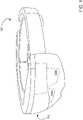
- FIG. 1shows an example head-mounted display system 100 including a display device 102 positioned near a wearer's eyes.
- the display device 102includes left-eye and right-eye displays 104a, 104b each comprising see-through waveguides positioned to display virtual imagery in front of a view of a real-world environment for augmented and/or mixed reality applications.
- a display devicemay include a shared display extending over both eyes, rather than separate right and left eye displays.
- the displays 104a, 104bmay comprise opaque world-facing surfaces (or otherwise block transmission of external light) for use in virtual reality applications.
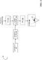
- FIG. 2shows a block diagram of an example display device 200, which may be implemented as head-mounted display system 100.
- the display device 200includes a light engine 202, a collimating optic 204, and a curved waveguide 206 configured to deliver images from the light engine 202 to an eyebox 208 in which a user's pupil 210 may be positioned for viewing.
- the curved waveguide 206is at least partially transparent, and may function as an optical combiner that combines virtual display imagery and real-world background imagery in the user's field of view.
- a lens 212may be used to compensate for any distortion of the real-world background view due to viewing the real-world background through the waveguide.
- FIG. 2illustrates to optional positions 212a and 212b at which a lens 212 may be positioned.
- the curved waveguide 206comprises a curvature in a direction transverse to an optical path between an input coupler and an output coupler. Further, a radius of the curvature varies along a direction extending between the input coupler and the output coupler. In some examples, a shape of the curved waveguide 206 may resemble a partial cone having a radius that increases from the input coupler toward the output coupler. The curvature of the curved waveguide 206 creates a lens effect, which expands an exit pupil of the light engine in a corresponding dimension.
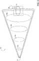
- FIG. 3shows an example curved waveguide 300 that may be used as the curved waveguide 206 of FIG. 2 .
- the curved waveguide 300comprises an input coupler 302, a first reflective surface 304, an opposing second reflective surface 306, and an output coupler 308.
- the input coupler 302is located proximate to an end of the curved waveguide having a smaller radius.
- the input coupler 302may utilize any suitable optical component to couple light into the curved waveguide 300, including but not limited to diffractive and reflective structures.
- the input coupler 302is configured to couple light of two or more wavelength bands into the curved waveguide 300, for example, via diffractive gratings having different grating properties (e.g. fill factor, slant, depth).
- different volume gratingsconfigured to couple different wavelength bands of light into the curved waveguide 300 may be superimposed on top of one another to couple the light of two or more wavelength bands into the curved waveguide 300.
- a single waveguidemay be used for all three color bands of a color display. While depicted as being located at a world-facing surface 310 of the curved waveguide 300 in the example of FIG. 3 , the input coupler 302 also may be located at an eye-facing surface 312, at an edge of the narrower end of the curved waveguide 300, or at any other suitable location. Further, in some examples, the input coupler 302 may comprise optical power.
- TIRtotal internal reflection
- one or both of the opposing reflective surfaces 304, 306may comprise a coating.
- one or both of the opposing reflective surfaces 304, 306may comprise an optically transparent cladding material comprising an index of refraction selected to provide a desired critical angle for TIR based upon an index of refraction of the material from which the waveguide is formed.
- one or both of the opposing reflective surfaces 304, 306may be at least partially coated with a multilayer dielectric coating configured to reflect one or more wavelengths of interest, such as red, green and/or blue wavelengths output by the light engine, and transmit other wavelengths.
- the curved waveguide 300may be uncoated.
- the first reflective surface 304 and the second reflective surface 306are at least partially transparent such that a real-world background image is viewable through the curved waveguide 300 in an augmented reality configuration.
- a world-facing surface of the curved waveguide 300may be opaque (e.g. coated with a metallic mirror layer) in a virtual reality configuration.
- at least a portion of the inner-facing surface of the waveguidealso may be coated with a reflective, opaque layer.
- FIG.4schematically shows a top view of the curved waveguide 300 of FIG. 3 , in which ellipses 400a-400d illustrate this expansion along a direction between the input coupler 302 and the output coupler 308.
- the output coupler 308couples the light out of the curved waveguide 300 and steers the light towards an eyebox 310.
- the output coupler 308comprises any suitable structure configured to couple light out of the waveguide, including diffractive and reflective structures.
- different gratingsconfigured to couple different wavelength bands of light out of the curved waveguide 300 may be superimposed on top of one another to couple the light of two or more wavelength bands out of the curved waveguide 300.
- the output coupler 308may be chirped to further expand a field of view of a displayed image vertically and/or horizontally, for example, by varying a grating period of the output coupler 308. Changing a grating period locally at the output coupler 308 may change a direction of a field of the view of a displayed image, which may effectively expand the field of view.
- the output coupler 308may comprise optical power.
- the curved waveguide 300 as disclosed hereinis configured to provide an output in which light corresponding to different portions of a field of view overlap within the eyebox 310.
- exit pupils corresponding to different portions of a field of viewmay be sufficiently coincident in a viewing region, shown by an overlap region 312, that the different portions of the field of view are viewable at a same eye location.
- thismay help to prevent loss of imagery as a user moves their eyes from side-to-side, and also may provide a sufficiently large eyebox for users of varying interpupillary sizes.
- the radius of curvaturecomprises a gradient that is substantially constant along the direction extending between the input coupler 302 and the output coupler 308.
- the curvature of the curved waveguide 300may differ from that shown in FIGS. 3 and 4 .
- a radius of curvature of the curved waveguide 300may comprise a gradient that varies along the direction extending between the input coupler 302 and the output coupler 308.
- the curvature of the curved waveguide 300may gradually flatten along the direction extending between the input coupler 302 and the output coupler 308.
- an axis 314 defining a center of curvature along the curved waveguide 300is linear.
- the axis 314may comprise curvature, for example, to more closely fit a curvature of a human face.
- the curve of this axis 314may follow an Euler bend.
- the curved waveguide 300may be formed from any suitable material or combination of materials. Examples include poly(methyl methacrylate), polycarbonate, and cycloolefin polymer. Further, the curved waveguide 300 may be formed via any suitable process, including molding, casting, and/or thermoforming. In some examples, the curved waveguide 300 may comprise a uniform thickness, while in other examples, the thickness may vary along a length of and/or a curvature of the curved waveguide 300.
- the light engine 202may utilize any suitable image-forming device.
- the light engine 202may comprise a liquid-crystal-on-silicon (LCOS) microdisplay, an organic light emitting device (OLED), or a scanning laser system.
- LCOSliquid-crystal-on-silicon
- OLEDorganic light emitting device
- each color fieldmay utilize a separate image producing element (e.g. a separate LCOS or OLED), while in other examples a same image-forming device may be used to form different color fields.
- the curvature of the curved waveguidemay exhibit a lensing effect with regard to a real-world background image.
- the display device 200further may include a lens 212 that has an optical power substantially inverse to an optical power of the curved waveguide 206 with regard to a view of the real-world background through the curved waveguide 206.
- the lens 212may be positioned between the curved waveguide 206 and the user's pupil 210, as shown in FIG. 2 , or alternatively may be positioned on an opposite side of the curved waveguide 206 as the user's pupil 210.
- the lens 212may be selected to provide a substantially undistorted view of the real-world background.
- the lens 212may be configured to compensate for vision deficiency of a user of the display device 200, for example, by having a specific eyeglass prescription for a user. It will be understood that the display device 200 may include additional optical elements not depicted in FIG. 2 .
- aa curved waveguide 206may introduce aberrations to an image received from the image engine.
- the display device 200may be configured to pre-aberrate an image prior to introducing the image to the input coupler of the curved waveguide 206 to compensate for any waveguide-induced aberrations. This may be accomplished by encoding the aberrations into an image itself, for example by preprocessing an image prior to output by the light engine 202.
- display optics positioned between the light engine 202 and the curved waveguide 206also may be used to introduce compensatory aberrations.
- the examples disclosed hereinmay help to provide for a compact waveguide configured to expand an exit pupil of a small pupil projector for multiple wavelength bands of light while maintaining a relatively wide field of view. Further, the curvature of the curved waveguide also may provide an aesthetically pleasing display device, akin to regular eyeglasses or sunglasses.
- a curved waveguidecomprising an input coupler configured to couple light into the curved waveguide, a first reflective surface, a second reflective surface opposing the first reflective surface, and an output coupler configured to couple the light out of the curved waveguide, the curved waveguide comprising a curvature in a direction transverse to an optical path between the input coupler and the output coupler, the curvature comprising a radius that varies along a direction extending between the input coupler and the output coupler.
- one or more of the input coupler and/or the output couplermay additionally or alternatively comprise a diffractive structure having optical power.
- the curved waveguidemay additionally or alternatively comprise a uniform thickness.
- the radiusmay additionally or alternatively comprise a gradient that varies along the direction extending between the input coupler and the output coupler.
- an axis defining a center at any location along the curved waveguidemay additionally or alternatively follow an Euler bend.
- the curvature of the curved waveguidemay additionally or alternatively be substantially flat at the output coupler.
- the input couplermay additionally or alternatively be configured to couple light of two or more wavelength bands into the curved waveguide.
- one or more of the input coupler and/or the output couplermay additionally or alternatively comprise two or more diffractive structures superimposed, each diffractive structure configured to couple light of a wavelength band into the curved waveguide.
- a head-mounted display devicecomprising a light engine, a collimating optic positioned optically downstream of the light engine, and a curved waveguide comprising an input coupler configured to couple collimated light from the collimating optic into the waveguide, a first reflective surface, a second reflective surface opposing the first reflective surface, and an output coupler configured to outcouple light to an eyebox, the curved waveguide comprising a curvature in a direction transverse to an optical path between the input coupler and the output coupler, the curvature comprising a radius that varies along a direction extending between the input coupler and the output coupler.
- the head-mounted display devicemay additionally or alternatively comprise optics configured to pre-aberrate an image prior to introducing the image to the input coupler.
- the curved waveguidemay additionally or alternatively be at least partially transparent such that a real-world background image is viewable through the curved waveguide.
- the head-mounted display devicemay additionally or alternatively comprise a lens, an optical power of the lens being inverse to an optical power of the curved waveguide with regard to the real-world background image.
- the curved waveguidemay additionally or alternatively comprise a uniform thickness.
- the radiusmay additionally or alternatively comprise a gradient that varies along the direction extending between the input coupler and the output coupler.
- an axis defining a center at any location along the curved waveguidemay additionally or alternatively follow an Euler bend.
- the curvature of the curved waveguidemay additionally or alternatively be substantially flat at the output coupler.
- the input couplermay additionally or alternatively be configured to couple light of two or more wavelength bands into the curved waveguide.
- the output couplermay additionally or alternatively be configured to outcouple light corresponding to different portions of a field of view such the different portions of the field of view are viewable at a same pupil location.
- a display devicecomprising a light engine, a curved waveguide comprising an input coupler configured to couple a pupil output by the light engine into the waveguide, an output coupler configured to outcouple light to a viewing region, and a first reflective surface and a second reflective surface opposing the first reflective surface, the first reflective surface and the second reflective surface configured to replicate the pupil as the pupil propagates along a direction extending between the input coupler and the output coupler, the curved waveguide comprising a curvature in a direction transverse to an optical path between the input coupler and the output coupler, the curvature comprising a radius that varies along a direction extending between the input coupler and the output coupler, and the display device also comprising a lens comprising an optical power configured to compensate for an optical power of the waveguide with respect to a real-world background image.
- the optical power of the lensmay additionally or alternatively be configured to compensate for a vision deficiency of a user.
Landscapes
- Physics & Mathematics (AREA)
- General Physics & Mathematics (AREA)
- Optics & Photonics (AREA)
Description
- A near-eye display device may utilize a waveguide to deliver an image from a light engine to a user's eye. In an augmented reality display device, a waveguide may be configured as a combiner that allows the simultaneous viewing of displayed virtual imagery delivered via the waveguide and a real-world background viewed through the waveguide.
US 2012/0300311 A1 relates to a projection display for displaying an image to a viewer, comprising a curved waveguide made of light transmissive material and having first and second opposed curvilinear Surfaces, an image-providing light Source device arranged to inject collimated image bearing light into the waveguide, an input grating coupled to or within the waveguide to diffract said image bearing light to propagate internally along the curved waveguide by total internal reflection, an output grating provided along a side of the waveguide by which the image bearing light is diffracted out of the waveguide for viewing by the viewer, wherein the input grating and output grating have variable pitch gratings so that a collimated image injected into the waveguide can be output from the waveguide as a collimated image having an increased exit pupil.US 2015/0062707 A1 refers to a head-mounted or helmet-mounted display. The apparatus includes an optical element, which in use is disposed in front of the eyes of a user. The optical element comprises a waveguide portion. The apparatus further includes a first light source and a second light source of image-bearing light. The apparatus further includes a first diffraction element for propagation of image-bearing light of the first light source through the optical element. The apparatus further includes a second diffraction element for propagation of image-bearing light of the second light source through the optical element. The first light source and the second light source is disposed such that relative angular movement of the first light source and the second light source about an axis of symmetry of the optical element adjusts the inter-pupillary spacing of a first visible image and a second visible image presented to a respective eye of a user.JP H06 3641 A - It is the object of the present invention to provide an expanded exit pupil for a near-eye display device.
- This object is solved by the subject matter of independent claim 1.
- Preferred embodiments are defined in the dependent claims.
- This Summary is provided to introduce a selection of concepts in a simplified form that are further described below in the Detailed Description. This Summary is not intended to identify key features or essential features of the claimed subject matter, nor is it intended to be used to limit the scope of the claimed subject matter. Furthermore, the claimed subject matter is not limited to implementations that solve any or all disadvantages noted in any part of this disclosure.
- Examples are disclosed that relate to expanding an exit pupil of a display device via a curved waveguide. One example provides a curved waveguide including an input coupler configured to couple light into the curved waveguide, a first reflective surface, a second reflective surface opposing the first reflective surface, and an output coupler configured to couple the light out of the curved waveguide. The curved waveguide comprises a curvature in a direction transverse to an optical path between the input coupler and the output coupler, the curvature having a radius that varies along a direction extending between the input coupler and the output coupler.
FIG. 1 shows an example head-mounted display device.FIG. 2 shows a block diagram of an example display device.FIG. 3 shows a perspective view of an example curved waveguide.FIG. 4 shows a top view of the example curved waveguide ofFIG. 3 .- As mentioned above, a near-eye display device, such as a head-mounted display (HMD) device, may utilize a waveguide to display an image. In augmented reality display devices, the waveguide may permit the combined viewing of displayed virtual imagery and a real-world background. Such display devices may utilize a projector having a small exit pupil (e.g. on the order of 0.5mm) to produce images for display. However, the use of a small pupil projector may not provide a sufficiently large eyebox (a region of space in which an entire displayed image is visible without vignetting) to accommodate a wide variety of interpupillary distances (IPDs) and possible pupil positions. For example, the human eye moves approximately 10mm when gazing from the side to side. Where a same display device design is to accommodate people with both large and small interpupillary distances, the eyebox of the device may need to be even larger, such as 16 mm or even greater, to avoid vignetting when users with large or small IPDs move their eyes to the side of the field of view.
- One possible solution may be to replicate the exit pupil via a waveguide having a turning grating with diagonal grating lines. Such gratings may be used to expand the exit pupil in both horizontal and vertical directions. However, such gratings may be sensitive to manufacturing variations, may cause light loss, and may require a relatively large waveguide surface area. For example, a variation as small as approximately 5 nm in grating depth over a grating region may create strong interference, which may result in color nonuniformities in a displayed image. A larger pupil projector also may be used to increase an exit pupil size, but may increase the device size.
- The use of diffractive structures to expand an exit pupil further may reduce a field of view. Using separate waveguides to incouple and expand light of different wavelength bands (e.g. separate waveguides for red, green, and blue light) may help to address this. For example, a display device may include three planar waveguides in a "stacked" arrangement that each include wavelength-selective input gratings for coupling light of a certain wavelength band into the waveguide. However, a stacked arrangement increases device size and cost, and also may not greatly improve the field of view (e.g. field of view may be limited to 40°).
- Further, in a planar waveguide, light corresponding to different directions of a field of view diverge. When these different directions of a field of view are not output to substantially the same location spatially, a user may not view each portion of the field of view together, but instead may perceive each portion separately as the user's pupil moves side-to-side, which may impact a user experience.
- Accordingly, examples are disclosed that relate to expanding an exit pupil of a display device via a curved waveguide. Briefly, the disclosed examples expand an exit pupil of a light engine in a first dimension via pupil replication as the light propagates along a waveguide, and in a second dimension by a curved shape of the waveguide. The curvature of the waveguide effectively breaks the optical invariant that limits pupil expansion using geometrical optics. The curvature of the curved waveguide further helps to position exit pupils corresponding to different portions of a wide field of view at substantially a same location, thereby allowing an entire field of view of displayed virtual imagery to be viewed from a same eye position.
FIG. 1 shows an example head-mounteddisplay system 100 including adisplay device 102 positioned near a wearer's eyes. Thedisplay device 102 includes left-eye and right-eye displays displays FIG. 2 shows a block diagram of anexample display device 200, which may be implemented as head-mounteddisplay system 100. Thedisplay device 200 includes alight engine 202, a collimating optic 204, and acurved waveguide 206 configured to deliver images from thelight engine 202 to aneyebox 208 in which a user'spupil 210 may be positioned for viewing. In some examples, thecurved waveguide 206 is at least partially transparent, and may function as an optical combiner that combines virtual display imagery and real-world background imagery in the user's field of view. Further, in some examples, a lens 212 may be used to compensate for any distortion of the real-world background view due to viewing the real-world background through the waveguide.FIG. 2 illustrates tooptional positions - The
curved waveguide 206 comprises a curvature in a direction transverse to an optical path between an input coupler and an output coupler. Further, a radius of the curvature varies along a direction extending between the input coupler and the output coupler. In some examples, a shape of thecurved waveguide 206 may resemble a partial cone having a radius that increases from the input coupler toward the output coupler. The curvature of thecurved waveguide 206 creates a lens effect, which expands an exit pupil of the light engine in a corresponding dimension. FIG. 3 shows an examplecurved waveguide 300 that may be used as thecurved waveguide 206 ofFIG. 2 . Thecurved waveguide 300 comprises aninput coupler 302, a firstreflective surface 304, an opposing secondreflective surface 306, and anoutput coupler 308.- The
input coupler 302 is located proximate to an end of the curved waveguide having a smaller radius. Theinput coupler 302 may utilize any suitable optical component to couple light into thecurved waveguide 300, including but not limited to diffractive and reflective structures. In some examples, theinput coupler 302 is configured to couple light of two or more wavelength bands into thecurved waveguide 300, for example, via diffractive gratings having different grating properties (e.g. fill factor, slant, depth). In some such examples, different volume gratings configured to couple different wavelength bands of light into thecurved waveguide 300 may be superimposed on top of one another to couple the light of two or more wavelength bands into thecurved waveguide 300. Further, in some such examples, a single waveguide may be used for all three color bands of a color display. While depicted as being located at a world-facingsurface 310 of thecurved waveguide 300 in the example ofFIG. 3 , theinput coupler 302 also may be located at an eye-facingsurface 312, at an edge of the narrower end of thecurved waveguide 300, or at any other suitable location. Further, in some examples, theinput coupler 302 may comprise optical power. - Light coupled into the
curved waveguide 300 is directed towards the secondreflective surface 306, which reflects and redirects the light toward the firstreflective surface 304, for example by total internal reflection (TIR). As the light propagates along thecurved waveguide 300 toward theoutput coupler 308, the light repeatedly reflects from the firstreflective surface 304 and the secondreflective surface 306. This replicates an exit pupil of a light engine and effectively expands the exit pupil in a second dimension. - In some examples, one or both of the opposing
reflective surfaces reflective surfaces reflective surfaces curved waveguide 300 may be uncoated. In each of these examples, the firstreflective surface 304 and the secondreflective surface 306 are at least partially transparent such that a real-world background image is viewable through thecurved waveguide 300 in an augmented reality configuration. In further examples, a world-facing surface of thecurved waveguide 300 may be opaque (e.g. coated with a metallic mirror layer) in a virtual reality configuration. In such an example, at least a portion of the inner-facing surface of the waveguide also may be coated with a reflective, opaque layer. - As mentioned above, the curvature of the
curved waveguide 300 creates a lens effect which expands an exit pupil of the light engine in a dimension of the curvature.FIG.4 schematically shows a top view of thecurved waveguide 300 ofFIG. 3 , in which ellipses 400a-400d illustrate this expansion along a direction between theinput coupler 302 and theoutput coupler 308. - Continuing with
FIG. 3 , theoutput coupler 308 couples the light out of thecurved waveguide 300 and steers the light towards aneyebox 310. Theoutput coupler 308 comprises any suitable structure configured to couple light out of the waveguide, including diffractive and reflective structures. In some examples, different gratings configured to couple different wavelength bands of light out of thecurved waveguide 300 may be superimposed on top of one another to couple the light of two or more wavelength bands out of thecurved waveguide 300. Additionally or alternatively, in some examples, theoutput coupler 308 may be chirped to further expand a field of view of a displayed image vertically and/or horizontally, for example, by varying a grating period of theoutput coupler 308. Changing a grating period locally at theoutput coupler 308 may change a direction of a field of the view of a displayed image, which may effectively expand the field of view. Further, in some examples, theoutput coupler 308 may comprise optical power. - In contrast to a planar waveguide in which different portions of a field of view diverge at an output coupler, the
curved waveguide 300 as disclosed herein is configured to provide an output in which light corresponding to different portions of a field of view overlap within theeyebox 310. In this manner, exit pupils corresponding to different portions of a field of view (e.g. different field of view angles) may be sufficiently coincident in a viewing region, shown by anoverlap region 312, that the different portions of the field of view are viewable at a same eye location. In the example of a head-mounted display device, this may help to prevent loss of imagery as a user moves their eyes from side-to-side, and also may provide a sufficiently large eyebox for users of varying interpupillary sizes. - In
FIGS. 3 and4 , the radius of curvature comprises a gradient that is substantially constant along the direction extending between theinput coupler 302 and theoutput coupler 308. In other examples, the curvature of thecurved waveguide 300 may differ from that shown inFIGS. 3 and4 . For example, a radius of curvature of thecurved waveguide 300 may comprise a gradient that varies along the direction extending between theinput coupler 302 and theoutput coupler 308. As a more specific example, the curvature of thecurved waveguide 300 may gradually flatten along the direction extending between theinput coupler 302 and theoutput coupler 308. - In the example of
FIG. 3 , anaxis 314 defining a center of curvature along thecurved waveguide 300 is linear. In other examples, theaxis 314 may comprise curvature, for example, to more closely fit a curvature of a human face. In a more specific example, the curve of thisaxis 314 may follow an Euler bend. - The
curved waveguide 300 may be formed from any suitable material or combination of materials. Examples include poly(methyl methacrylate), polycarbonate, and cycloolefin polymer. Further, thecurved waveguide 300 may be formed via any suitable process, including molding, casting, and/or thermoforming. In some examples, thecurved waveguide 300 may comprise a uniform thickness, while in other examples, the thickness may vary along a length of and/or a curvature of thecurved waveguide 300. - Returning to
FIG. 2 , thelight engine 202 may utilize any suitable image-forming device. In various examples, thelight engine 202 may comprise a liquid-crystal-on-silicon (LCOS) microdisplay, an organic light emitting device (OLED), or a scanning laser system. In some examples, each color field may utilize a separate image producing element (e.g. a separate LCOS or OLED), while in other examples a same image-forming device may be used to form different color fields. - As mentioned above, the curvature of the curved waveguide may exhibit a lensing effect with regard to a real-world background image. To compensate for this lensing effect, the
display device 200 further may include a lens 212 that has an optical power substantially inverse to an optical power of thecurved waveguide 206 with regard to a view of the real-world background through thecurved waveguide 206. When included, the lens 212 may be positioned between thecurved waveguide 206 and the user'spupil 210, as shown inFIG. 2 , or alternatively may be positioned on an opposite side of thecurved waveguide 206 as the user'spupil 210. In any example, the lens 212 may be selected to provide a substantially undistorted view of the real-world background. Further, in some examples, the lens 212 may be configured to compensate for vision deficiency of a user of thedisplay device 200, for example, by having a specific eyeglass prescription for a user. It will be understood that thedisplay device 200 may include additional optical elements not depicted inFIG. 2 . - In some examples, aa
curved waveguide 206 may introduce aberrations to an image received from the image engine. Thus, in some such examples, thedisplay device 200 may be configured to pre-aberrate an image prior to introducing the image to the input coupler of thecurved waveguide 206 to compensate for any waveguide-induced aberrations. This may be accomplished by encoding the aberrations into an image itself, for example by preprocessing an image prior to output by thelight engine 202. In other examples, display optics positioned between thelight engine 202 and thecurved waveguide 206 also may be used to introduce compensatory aberrations. - The examples disclosed herein may help to provide for a compact waveguide configured to expand an exit pupil of a small pupil projector for multiple wavelength bands of light while maintaining a relatively wide field of view. Further, the curvature of the curved waveguide also may provide an aesthetically pleasing display device, akin to regular eyeglasses or sunglasses.
- Another example provides a curved waveguide, comprising an input coupler configured to couple light into the curved waveguide, a first reflective surface, a second reflective surface opposing the first reflective surface, and an output coupler configured to couple the light out of the curved waveguide, the curved waveguide comprising a curvature in a direction transverse to an optical path between the input coupler and the output coupler, the curvature comprising a radius that varies along a direction extending between the input coupler and the output coupler. In such an example, one or more of the input coupler and/or the output coupler may additionally or alternatively comprise a diffractive structure having optical power. In such an example, the curved waveguide may additionally or alternatively comprise a uniform thickness. In such an example, the radius may additionally or alternatively comprise a gradient that varies along the direction extending between the input coupler and the output coupler. In such an example, an axis defining a center at any location along the curved waveguide may additionally or alternatively follow an Euler bend. In such an example, the curvature of the curved waveguide may additionally or alternatively be substantially flat at the output coupler. In such an example, the input coupler may additionally or alternatively be configured to couple light of two or more wavelength bands into the curved waveguide. In such an example, one or more of the input coupler and/or the output coupler may additionally or alternatively comprise two or more diffractive structures superimposed, each diffractive structure configured to couple light of a wavelength band into the curved waveguide.
- Another example provides a head-mounted display device, comprising a light engine, a collimating optic positioned optically downstream of the light engine, and a curved waveguide comprising an input coupler configured to couple collimated light from the collimating optic into the waveguide, a first reflective surface, a second reflective surface opposing the first reflective surface, and an output coupler configured to outcouple light to an eyebox, the curved waveguide comprising a curvature in a direction transverse to an optical path between the input coupler and the output coupler, the curvature comprising a radius that varies along a direction extending between the input coupler and the output coupler. In such an example, the head-mounted display device may additionally or alternatively comprise optics configured to pre-aberrate an image prior to introducing the image to the input coupler. In such an example, the curved waveguide may additionally or alternatively be at least partially transparent such that a real-world background image is viewable through the curved waveguide. In such an example, the head-mounted display device may additionally or alternatively comprise a lens, an optical power of the lens being inverse to an optical power of the curved waveguide with regard to the real-world background image. In such an example, the curved waveguide may additionally or alternatively comprise a uniform thickness. In such an example, the radius may additionally or alternatively comprise a gradient that varies along the direction extending between the input coupler and the output coupler. In such an example, an axis defining a center at any location along the curved waveguide may additionally or alternatively follow an Euler bend. In such an example, the curvature of the curved waveguide may additionally or alternatively be substantially flat at the output coupler. In such an example, the input coupler may additionally or alternatively be configured to couple light of two or more wavelength bands into the curved waveguide. In such an example, the output coupler may additionally or alternatively be configured to outcouple light corresponding to different portions of a field of view such the different portions of the field of view are viewable at a same pupil location.
- Another example provides a display device, comprising a light engine, a curved waveguide comprising an input coupler configured to couple a pupil output by the light engine into the waveguide, an output coupler configured to outcouple light to a viewing region, and a first reflective surface and a second reflective surface opposing the first reflective surface, the first reflective surface and the second reflective surface configured to replicate the pupil as the pupil propagates along a direction extending between the input coupler and the output coupler, the curved waveguide comprising a curvature in a direction transverse to an optical path between the input coupler and the output coupler, the curvature comprising a radius that varies along a direction extending between the input coupler and the output coupler, and the display device also comprising a lens comprising an optical power configured to compensate for an optical power of the waveguide with respect to a real-world background image. In such an example, the optical power of the lens may additionally or alternatively be configured to compensate for a vision deficiency of a user.
- It will be understood that the configurations and/or approaches described herein are illustrative in nature, and that these specific embodiments or examples are not to be considered in a limiting sense, because numerous variations are possible.
Claims (15)
- A curved waveguide (206, 300), comprising:an input coupler (302) configured to couple light into the curved waveguide;a first reflective surface (304);a second reflective surface (306) opposing the first reflective surface; andan output coupler (308) configured to couple the light out of the curved waveguide, the curved waveguide comprising a curvaturecharacterized in that said curvature is in a direction transverse to an optical path between the input coupler and the output coupler, the curvature comprising a radius that varies along a direction extending between the input coupler and the output coupler.
- The curved waveguide of claim 1, wherein one or more of the input coupler and/or the output coupler comprises a diffractive structure having optical power.
- The curved waveguide of claim 1, wherein the curved waveguide comprises a uniform thickness.
- The curved waveguide of claim 1, wherein the radius comprises a gradient that varies along the direction extending between the input coupler and the output coupler.
- The curved waveguide of claim 1, wherein an axis defining a center at any location along the curved waveguide follows an Euler bend.
- The curved waveguide of claim 1, wherein the curvature of the curved waveguide is substantially flat at the output coupler.
- The curved waveguide of claim 1, wherein the input coupler is configured to couple light of two or more wavelength bands into the curved waveguide.
- The curved waveguide of claim 7, wherein one or more of the input coupler and the output coupler comprises two or more diffractive structures superimposed, each diffractive structure configured to couple light of a wavelength band.
- A head-mounted display device, comprising:a light engine (202);a collimating optic (204) positioned optically downstream of the light engine; anda curved waveguide (206, 300) according to claim 1.
- The head-mounted display device of claim 9, further comprising optics configured to pre-aberrate an image prior to introducing the image to the input coupler.
- The head-mounted display device of claim 9, further comprising a lens, an optical power of the lens being inverse to an optical power of the curved waveguide with regard to a real-world background image viewable through the curved waveguide.
- The head-mounted display device of claim 9, wherein the radius comprises a gradient that varies along the direction extending between the input coupler and the output coupler.
- The head-mounted display device of claim 9, wherein an axis defining a center at any location along the curved waveguide follows an Euler bend.
- The head-mounted display device of claim 9, wherein the curvature of the curved waveguide is substantially flat at the output coupler.
- The head-mounted display device of claim 9, wherein the input coupler is configured to couple light of two or more wavelength bands into the curved waveguide.
Applications Claiming Priority (2)
| Application Number | Priority Date | Filing Date | Title |
|---|---|---|---|
| US16/201,888US10962782B2 (en) | 2018-11-27 | 2018-11-27 | Exit pupil expansion via curved waveguide |
| PCT/US2019/062086WO2020112422A1 (en) | 2018-11-27 | 2019-11-19 | Exit pupil expansion via curved waveguide |
Publications (2)
| Publication Number | Publication Date |
|---|---|
| EP3887888A1 EP3887888A1 (en) | 2021-10-06 |
| EP3887888B1true EP3887888B1 (en) | 2023-01-25 |
Family
ID=68887138
Family Applications (1)
| Application Number | Title | Priority Date | Filing Date |
|---|---|---|---|
| EP19820946.2AActiveEP3887888B1 (en) | 2018-11-27 | 2019-11-19 | Exit pupil expansion via curved waveguide |
Country Status (3)
| Country | Link |
|---|---|
| US (1) | US10962782B2 (en) |
| EP (1) | EP3887888B1 (en) |
| WO (1) | WO2020112422A1 (en) |
Families Citing this family (7)
| Publication number | Priority date | Publication date | Assignee | Title |
|---|---|---|---|---|
| KR20220131720A (en)* | 2021-03-22 | 2022-09-29 | 삼성전자주식회사 | Display device including a combiner having an asymmetric magnification |
| WO2022232236A1 (en)* | 2021-04-28 | 2022-11-03 | Meta Platforms Technologies, Llc | Waveguide configurations in a head-mounted display (hmd) for improved field of view (fov) |
| US11960088B2 (en) | 2021-04-28 | 2024-04-16 | Meta Platforms Technologies, Llc | Waveguide configurations in a head-mounted display (HMD) for improved field of view (FOV) |
| US12105290B2 (en) | 2021-09-10 | 2024-10-01 | Google Llc | Optical design of a dual combiner in head-wearable display |
| WO2023129547A1 (en)* | 2021-12-31 | 2023-07-06 | Meta Platforms Technologies, Llc | Curved light guide image combiner and system including the same |
| US12399369B2 (en) | 2021-12-31 | 2025-08-26 | Meta Platforms Technologies, Llc | Curved light guide image combiner and system including the same |
| US12416808B2 (en) | 2023-04-24 | 2025-09-16 | Microsoft Technology Licensing, Llc | Waveguide combiner with separate in-coupling and out-coupling plates |
Family Cites Families (22)
| Publication number | Priority date | Publication date | Assignee | Title |
|---|---|---|---|---|
| JP2795779B2 (en) | 1992-06-19 | 1998-09-10 | シャープ株式会社 | Display panel |
| EP2229603B1 (en)* | 2007-12-17 | 2012-08-29 | Nokia Corporation | Exit pupil expanders with spherical and aspheric substrates |
| US10274660B2 (en)* | 2008-11-17 | 2019-04-30 | Luminit, Llc | Holographic substrate-guided wave-based see-through display |
| DE102009010537B4 (en)* | 2009-02-25 | 2018-03-01 | Carl Zeiss Smart Optics Gmbh | Beam combiner and use of such in a display device |
| ES2929791T3 (en) | 2009-04-29 | 2022-12-01 | Bae Systems Plc | head mounted display |
| EP2529268A1 (en) | 2010-01-25 | 2012-12-05 | BAE Systems Plc | Projection display |
| WO2012088478A1 (en)* | 2010-12-24 | 2012-06-28 | Chunyu Gao | An ergonomic head mounted display device and optical system |
| FI124843B (en)* | 2012-10-18 | 2015-02-13 | Teknologian Tutkimuskeskus Vtt | Bent optical waveguide |
| JP6244888B2 (en)* | 2013-09-03 | 2017-12-13 | セイコーエプソン株式会社 | Virtual image display device |
| JP6307857B2 (en)* | 2013-11-29 | 2018-04-11 | セイコーエプソン株式会社 | Virtual image display device |
| KR20170030594A (en)* | 2014-08-18 | 2017-03-17 | 세이코 엡슨 가부시키가이샤 | Light guide device and virtual image display apparatus |
| US9733475B1 (en)* | 2014-09-08 | 2017-08-15 | Rockwell Collins, Inc. | Curved waveguide combiner for head-mounted and helmet-mounted displays (HMDS), a collimated virtual window, or a head up display (HUD) |
| JP6464708B2 (en)* | 2014-12-08 | 2019-02-06 | セイコーエプソン株式会社 | Image display device |
| US10146054B2 (en)* | 2015-07-06 | 2018-12-04 | Google Llc | Adding prescriptive correction to eyepieces for see-through head wearable displays |
| US10038840B2 (en) | 2015-07-30 | 2018-07-31 | Microsoft Technology Licensing, Llc | Diffractive optical element using crossed grating for pupil expansion |
| CN113759555B (en) | 2015-10-05 | 2024-09-20 | 迪吉伦斯公司 | Waveguide Display |
| EP3205512B1 (en)* | 2016-02-09 | 2018-06-13 | CSEM Centre Suisse d'Electronique et de Microtechnique SA - Recherche et Développement | Optical security device |
| US10228565B1 (en)* | 2016-05-27 | 2019-03-12 | Facebook Technologies, Llc | Variable focus waveguide display |
| US10838146B2 (en)* | 2016-06-03 | 2020-11-17 | Rockley Photonics Limited | Single mode waveguide with an adiabatic bend |
| US10545346B2 (en) | 2017-01-05 | 2020-01-28 | Digilens Inc. | Wearable heads up displays |
| US10222620B2 (en) | 2017-02-15 | 2019-03-05 | Microsoft Technology Licensing, Llc | Pupil-expansion optic with offset entry apertures |
| US20180373046A1 (en)* | 2017-06-27 | 2018-12-27 | Thalmic Labs Inc. | Systems, devices, and methods for optical waveguides |
- 2018
- 2018-11-27USUS16/201,888patent/US10962782B2/enactiveActive
- 2019
- 2019-11-19EPEP19820946.2Apatent/EP3887888B1/enactiveActive
- 2019-11-19WOPCT/US2019/062086patent/WO2020112422A1/ennot_activeCeased
Also Published As
| Publication number | Publication date |
|---|---|
| US20200166753A1 (en) | 2020-05-28 |
| EP3887888A1 (en) | 2021-10-06 |
| US10962782B2 (en) | 2021-03-30 |
| WO2020112422A1 (en) | 2020-06-04 |
Similar Documents
| Publication | Publication Date | Title |
|---|---|---|
| EP3887888B1 (en) | Exit pupil expansion via curved waveguide | |
| US11921292B2 (en) | Systems, devices, and methods for waveguide-based eyebox expansion in wearable heads-up displays | |
| JP6994940B2 (en) | Head-mounted imaging device using optical coupling | |
| JP6774429B2 (en) | Addition of prescription modifications to eyepieces for see-through headwearable displays | |
| US11237394B2 (en) | Freeform head mounted display | |
| CN112925100B (en) | Optical system | |
| JP7514852B2 (en) | A waveguide for transmitting light | |
| CN118169876A (en) | Head mounted display with pivoting imaging light guide | |
| EP3134763A1 (en) | Compact architecture for near-to-eye display system | |
| EP3602172B1 (en) | Optical systems for electronic devices with displays | |
| CN110088666B (en) | Head-mounted display and optical system thereof | |
| CN118679346A (en) | Hybrid waveguide for maximizing coverage in field of view (FOV) | |
| CN118140474A (en) | Double-Sided Waveguide | |
| EP4024120B1 (en) | Optical display system and method, and display device | |
| US20220128756A1 (en) | Display system for generating three-dimensional image and method therefor | |
| US20240210611A1 (en) | Lightguide with polarization-selective bulk reflectors | |
| Yoshikaie et al. | 68‐1: Invited Paper: A Waveguide‐type Retinal Scan AR Display with Pupil Expansion System | |
| WO2022258885A1 (en) | An optical waveguide arrangement with improved capacity | |
| EP4623579A1 (en) | Binocular alignment of virtual image displays | |
| WO2024137483A1 (en) | Lightguide with polarization-selective bulk reflectors |
Legal Events
| Date | Code | Title | Description |
|---|---|---|---|
| STAA | Information on the status of an ep patent application or granted ep patent | Free format text:STATUS: UNKNOWN | |
| STAA | Information on the status of an ep patent application or granted ep patent | Free format text:STATUS: THE INTERNATIONAL PUBLICATION HAS BEEN MADE | |
| PUAI | Public reference made under article 153(3) epc to a published international application that has entered the european phase | Free format text:ORIGINAL CODE: 0009012 | |
| STAA | Information on the status of an ep patent application or granted ep patent | Free format text:STATUS: REQUEST FOR EXAMINATION WAS MADE | |
| 17P | Request for examination filed | Effective date:20210505 | |
| AK | Designated contracting states | Kind code of ref document:A1 Designated state(s):AL AT BE BG CH CY CZ DE DK EE ES FI FR GB GR HR HU IE IS IT LI LT LU LV MC MK MT NL NO PL PT RO RS SE SI SK SM TR | |
| RAP3 | Party data changed (applicant data changed or rights of an application transferred) | Owner name:MICROSOFT TECHNOLOGY LICENSING, LLC | |
| DAV | Request for validation of the european patent (deleted) | ||
| DAX | Request for extension of the european patent (deleted) | ||
| GRAP | Despatch of communication of intention to grant a patent | Free format text:ORIGINAL CODE: EPIDOSNIGR1 | |
| STAA | Information on the status of an ep patent application or granted ep patent | Free format text:STATUS: GRANT OF PATENT IS INTENDED | |
| INTG | Intention to grant announced | Effective date:20220824 | |
| GRAS | Grant fee paid | Free format text:ORIGINAL CODE: EPIDOSNIGR3 | |
| GRAA | (expected) grant | Free format text:ORIGINAL CODE: 0009210 | |
| STAA | Information on the status of an ep patent application or granted ep patent | Free format text:STATUS: THE PATENT HAS BEEN GRANTED | |
| AK | Designated contracting states | Kind code of ref document:B1 Designated state(s):AL AT BE BG CH CY CZ DE DK EE ES FI FR GB GR HR HU IE IS IT LI LT LU LV MC MK MT NL NO PL PT RO RS SE SI SK SM TR | |
| REG | Reference to a national code | Ref country code:GB Ref legal event code:FG4D | |
| REG | Reference to a national code | Ref country code:CH Ref legal event code:EP | |
| REG | Reference to a national code | Ref country code:NL Ref legal event code:FP Ref country code:AT Ref legal event code:REF Ref document number:1546279 Country of ref document:AT Kind code of ref document:T Effective date:20230215 Ref country code:IE Ref legal event code:FG4D | |
| REG | Reference to a national code | Ref country code:DE Ref legal event code:R096 Ref document number:602019024878 Country of ref document:DE | |
| REG | Reference to a national code | Ref country code:LT Ref legal event code:MG9D | |
| REG | Reference to a national code | Ref country code:AT Ref legal event code:MK05 Ref document number:1546279 Country of ref document:AT Kind code of ref document:T Effective date:20230125 | |
| P01 | Opt-out of the competence of the unified patent court (upc) registered | Effective date:20230522 | |
| PG25 | Lapsed in a contracting state [announced via postgrant information from national office to epo] | Ref country code:RS Free format text:LAPSE BECAUSE OF FAILURE TO SUBMIT A TRANSLATION OF THE DESCRIPTION OR TO PAY THE FEE WITHIN THE PRESCRIBED TIME-LIMIT Effective date:20230125 Ref country code:PT Free format text:LAPSE BECAUSE OF FAILURE TO SUBMIT A TRANSLATION OF THE DESCRIPTION OR TO PAY THE FEE WITHIN THE PRESCRIBED TIME-LIMIT Effective date:20230525 Ref country code:NO Free format text:LAPSE BECAUSE OF FAILURE TO SUBMIT A TRANSLATION OF THE DESCRIPTION OR TO PAY THE FEE WITHIN THE PRESCRIBED TIME-LIMIT Effective date:20230425 Ref country code:LV Free format text:LAPSE BECAUSE OF FAILURE TO SUBMIT A TRANSLATION OF THE DESCRIPTION OR TO PAY THE FEE WITHIN THE PRESCRIBED TIME-LIMIT Effective date:20230125 Ref country code:LT Free format text:LAPSE BECAUSE OF FAILURE TO SUBMIT A TRANSLATION OF THE DESCRIPTION OR TO PAY THE FEE WITHIN THE PRESCRIBED TIME-LIMIT Effective date:20230125 Ref country code:HR Free format text:LAPSE BECAUSE OF FAILURE TO SUBMIT A TRANSLATION OF THE DESCRIPTION OR TO PAY THE FEE WITHIN THE PRESCRIBED TIME-LIMIT Effective date:20230125 Ref country code:ES Free format text:LAPSE BECAUSE OF FAILURE TO SUBMIT A TRANSLATION OF THE DESCRIPTION OR TO PAY THE FEE WITHIN THE PRESCRIBED TIME-LIMIT Effective date:20230125 Ref country code:AT Free format text:LAPSE BECAUSE OF FAILURE TO SUBMIT A TRANSLATION OF THE DESCRIPTION OR TO PAY THE FEE WITHIN THE PRESCRIBED TIME-LIMIT Effective date:20230125 | |
| PG25 | Lapsed in a contracting state [announced via postgrant information from national office to epo] | Ref country code:SE Free format text:LAPSE BECAUSE OF FAILURE TO SUBMIT A TRANSLATION OF THE DESCRIPTION OR TO PAY THE FEE WITHIN THE PRESCRIBED TIME-LIMIT Effective date:20230125 Ref country code:PL Free format text:LAPSE BECAUSE OF FAILURE TO SUBMIT A TRANSLATION OF THE DESCRIPTION OR TO PAY THE FEE WITHIN THE PRESCRIBED TIME-LIMIT Effective date:20230125 Ref country code:IS Free format text:LAPSE BECAUSE OF FAILURE TO SUBMIT A TRANSLATION OF THE DESCRIPTION OR TO PAY THE FEE WITHIN THE PRESCRIBED TIME-LIMIT Effective date:20230525 Ref country code:GR Free format text:LAPSE BECAUSE OF FAILURE TO SUBMIT A TRANSLATION OF THE DESCRIPTION OR TO PAY THE FEE WITHIN THE PRESCRIBED TIME-LIMIT Effective date:20230426 Ref country code:FI Free format text:LAPSE BECAUSE OF FAILURE TO SUBMIT A TRANSLATION OF THE DESCRIPTION OR TO PAY THE FEE WITHIN THE PRESCRIBED TIME-LIMIT Effective date:20230125 | |
| REG | Reference to a national code | Ref country code:DE Ref legal event code:R097 Ref document number:602019024878 Country of ref document:DE | |
| PG25 | Lapsed in a contracting state [announced via postgrant information from national office to epo] | Ref country code:SM Free format text:LAPSE BECAUSE OF FAILURE TO SUBMIT A TRANSLATION OF THE DESCRIPTION OR TO PAY THE FEE WITHIN THE PRESCRIBED TIME-LIMIT Effective date:20230125 Ref country code:RO Free format text:LAPSE BECAUSE OF FAILURE TO SUBMIT A TRANSLATION OF THE DESCRIPTION OR TO PAY THE FEE WITHIN THE PRESCRIBED TIME-LIMIT Effective date:20230125 Ref country code:EE Free format text:LAPSE BECAUSE OF FAILURE TO SUBMIT A TRANSLATION OF THE DESCRIPTION OR TO PAY THE FEE WITHIN THE PRESCRIBED TIME-LIMIT Effective date:20230125 Ref country code:DK Free format text:LAPSE BECAUSE OF FAILURE TO SUBMIT A TRANSLATION OF THE DESCRIPTION OR TO PAY THE FEE WITHIN THE PRESCRIBED TIME-LIMIT Effective date:20230125 Ref country code:CZ Free format text:LAPSE BECAUSE OF FAILURE TO SUBMIT A TRANSLATION OF THE DESCRIPTION OR TO PAY THE FEE WITHIN THE PRESCRIBED TIME-LIMIT Effective date:20230125 | |
| PG25 | Lapsed in a contracting state [announced via postgrant information from national office to epo] | Ref country code:SK Free format text:LAPSE BECAUSE OF FAILURE TO SUBMIT A TRANSLATION OF THE DESCRIPTION OR TO PAY THE FEE WITHIN THE PRESCRIBED TIME-LIMIT Effective date:20230125 | |
| PLBE | No opposition filed within time limit | Free format text:ORIGINAL CODE: 0009261 | |
| STAA | Information on the status of an ep patent application or granted ep patent | Free format text:STATUS: NO OPPOSITION FILED WITHIN TIME LIMIT | |
| 26N | No opposition filed | Effective date:20231026 | |
| PG25 | Lapsed in a contracting state [announced via postgrant information from national office to epo] | Ref country code:SI Free format text:LAPSE BECAUSE OF FAILURE TO SUBMIT A TRANSLATION OF THE DESCRIPTION OR TO PAY THE FEE WITHIN THE PRESCRIBED TIME-LIMIT Effective date:20230125 | |
| PG25 | Lapsed in a contracting state [announced via postgrant information from national office to epo] | Ref country code:IT Free format text:LAPSE BECAUSE OF FAILURE TO SUBMIT A TRANSLATION OF THE DESCRIPTION OR TO PAY THE FEE WITHIN THE PRESCRIBED TIME-LIMIT Effective date:20230125 | |
| REG | Reference to a national code | Ref country code:CH Ref legal event code:PL | |
| PG25 | Lapsed in a contracting state [announced via postgrant information from national office to epo] | Ref country code:MC Free format text:LAPSE BECAUSE OF FAILURE TO SUBMIT A TRANSLATION OF THE DESCRIPTION OR TO PAY THE FEE WITHIN THE PRESCRIBED TIME-LIMIT Effective date:20230125 | |
| PG25 | Lapsed in a contracting state [announced via postgrant information from national office to epo] | Ref country code:LU Free format text:LAPSE BECAUSE OF NON-PAYMENT OF DUE FEES Effective date:20231119 | |
| PG25 | Lapsed in a contracting state [announced via postgrant information from national office to epo] | Ref country code:CH Free format text:LAPSE BECAUSE OF NON-PAYMENT OF DUE FEES Effective date:20231130 | |
| PG25 | Lapsed in a contracting state [announced via postgrant information from national office to epo] | Ref country code:MC Free format text:LAPSE BECAUSE OF FAILURE TO SUBMIT A TRANSLATION OF THE DESCRIPTION OR TO PAY THE FEE WITHIN THE PRESCRIBED TIME-LIMIT Effective date:20230125 Ref country code:LU Free format text:LAPSE BECAUSE OF NON-PAYMENT OF DUE FEES Effective date:20231119 Ref country code:CH Free format text:LAPSE BECAUSE OF NON-PAYMENT OF DUE FEES Effective date:20231130 | |
| REG | Reference to a national code | Ref country code:BE Ref legal event code:MM Effective date:20231130 | |
| REG | Reference to a national code | Ref country code:IE Ref legal event code:MM4A | |
| PG25 | Lapsed in a contracting state [announced via postgrant information from national office to epo] | Ref country code:IE Free format text:LAPSE BECAUSE OF NON-PAYMENT OF DUE FEES Effective date:20231119 | |
| PG25 | Lapsed in a contracting state [announced via postgrant information from national office to epo] | Ref country code:BE Free format text:LAPSE BECAUSE OF NON-PAYMENT OF DUE FEES Effective date:20231130 | |
| PG25 | Lapsed in a contracting state [announced via postgrant information from national office to epo] | Ref country code:IE Free format text:LAPSE BECAUSE OF NON-PAYMENT OF DUE FEES Effective date:20231119 Ref country code:BE Free format text:LAPSE BECAUSE OF NON-PAYMENT OF DUE FEES Effective date:20231130 | |
| PG25 | Lapsed in a contracting state [announced via postgrant information from national office to epo] | Ref country code:BG Free format text:LAPSE BECAUSE OF FAILURE TO SUBMIT A TRANSLATION OF THE DESCRIPTION OR TO PAY THE FEE WITHIN THE PRESCRIBED TIME-LIMIT Effective date:20230125 | |
| PGFP | Annual fee paid to national office [announced via postgrant information from national office to epo] | Ref country code:NL Payment date:20241022 Year of fee payment:6 | |
| PG25 | Lapsed in a contracting state [announced via postgrant information from national office to epo] | Ref country code:BG Free format text:LAPSE BECAUSE OF FAILURE TO SUBMIT A TRANSLATION OF THE DESCRIPTION OR TO PAY THE FEE WITHIN THE PRESCRIBED TIME-LIMIT Effective date:20230125 | |
| PGFP | Annual fee paid to national office [announced via postgrant information from national office to epo] | Ref country code:DE Payment date:20241022 Year of fee payment:6 | |
| PGFP | Annual fee paid to national office [announced via postgrant information from national office to epo] | Ref country code:GB Payment date:20241023 Year of fee payment:6 | |
| PGFP | Annual fee paid to national office [announced via postgrant information from national office to epo] | Ref country code:FR Payment date:20241022 Year of fee payment:6 | |
| PG25 | Lapsed in a contracting state [announced via postgrant information from national office to epo] | Ref country code:CY Free format text:LAPSE BECAUSE OF FAILURE TO SUBMIT A TRANSLATION OF THE DESCRIPTION OR TO PAY THE FEE WITHIN THE PRESCRIBED TIME-LIMIT; INVALID AB INITIO Effective date:20191119 | |
| PG25 | Lapsed in a contracting state [announced via postgrant information from national office to epo] | Ref country code:HU Free format text:LAPSE BECAUSE OF FAILURE TO SUBMIT A TRANSLATION OF THE DESCRIPTION OR TO PAY THE FEE WITHIN THE PRESCRIBED TIME-LIMIT; INVALID AB INITIO Effective date:20191119 |