EP3883094B1 - Horseshoe-type pm rotor for motor - Google Patents
Horseshoe-type pm rotor for motorDownload PDFInfo
- Publication number
- EP3883094B1 EP3883094B1EP21152667.8AEP21152667AEP3883094B1EP 3883094 B1EP3883094 B1EP 3883094B1EP 21152667 AEP21152667 AEP 21152667AEP 3883094 B1EP3883094 B1EP 3883094B1
- Authority
- EP
- European Patent Office
- Prior art keywords
- core
- rotor
- iron core
- magnets
- parts
- Prior art date
- Legal status (The legal status is an assumption and is not a legal conclusion. Google has not performed a legal analysis and makes no representation as to the accuracy of the status listed.)
- Active
Links
Images


Classifications
- H—ELECTRICITY
- H02—GENERATION; CONVERSION OR DISTRIBUTION OF ELECTRIC POWER
- H02K—DYNAMO-ELECTRIC MACHINES
- H02K1/00—Details of the magnetic circuit
- H02K1/06—Details of the magnetic circuit characterised by the shape, form or construction
- H02K1/22—Rotating parts of the magnetic circuit
- H02K1/27—Rotor cores with permanent magnets
- H02K1/2706—Inner rotors
- H02K1/272—Inner rotors the magnetisation axis of the magnets being perpendicular to the rotor axis
- H02K1/274—Inner rotors the magnetisation axis of the magnets being perpendicular to the rotor axis the rotor consisting of two or more circumferentially positioned magnets
- H02K1/2753—Inner rotors the magnetisation axis of the magnets being perpendicular to the rotor axis the rotor consisting of two or more circumferentially positioned magnets the rotor consisting of magnets or groups of magnets arranged with alternating polarity
- H02K1/276—Magnets embedded in the magnetic core, e.g. interior permanent magnets [IPM]
- H—ELECTRICITY
- H02—GENERATION; CONVERSION OR DISTRIBUTION OF ELECTRIC POWER
- H02K—DYNAMO-ELECTRIC MACHINES
- H02K1/00—Details of the magnetic circuit
- H02K1/06—Details of the magnetic circuit characterised by the shape, form or construction
- H02K1/22—Rotating parts of the magnetic circuit
- H02K1/28—Means for mounting or fastening rotating magnetic parts on to, or to, the rotor structures
- H02K1/30—Means for mounting or fastening rotating magnetic parts on to, or to, the rotor structures using intermediate parts, e.g. spiders
- H—ELECTRICITY
- H02—GENERATION; CONVERSION OR DISTRIBUTION OF ELECTRIC POWER
- H02K—DYNAMO-ELECTRIC MACHINES
- H02K1/00—Details of the magnetic circuit
- H02K1/06—Details of the magnetic circuit characterised by the shape, form or construction
- H02K1/22—Rotating parts of the magnetic circuit
- H02K1/32—Rotating parts of the magnetic circuit with channels or ducts for flow of cooling medium
- H—ELECTRICITY
- H02—GENERATION; CONVERSION OR DISTRIBUTION OF ELECTRIC POWER
- H02K—DYNAMO-ELECTRIC MACHINES
- H02K21/00—Synchronous motors having permanent magnets; Synchronous generators having permanent magnets
- H02K21/12—Synchronous motors having permanent magnets; Synchronous generators having permanent magnets with stationary armatures and rotating magnets
- H02K21/14—Synchronous motors having permanent magnets; Synchronous generators having permanent magnets with stationary armatures and rotating magnets with magnets rotating within the armatures
- H—ELECTRICITY
- H02—GENERATION; CONVERSION OR DISTRIBUTION OF ELECTRIC POWER
- H02K—DYNAMO-ELECTRIC MACHINES
- H02K7/00—Arrangements for handling mechanical energy structurally associated with dynamo-electric machines, e.g. structural association with mechanical driving motors or auxiliary dynamo-electric machines
- H02K7/003—Couplings; Details of shafts
- H—ELECTRICITY
- H02—GENERATION; CONVERSION OR DISTRIBUTION OF ELECTRIC POWER
- H02K—DYNAMO-ELECTRIC MACHINES
- H02K2213/00—Specific aspects, not otherwise provided for and not covered by codes H02K2201/00 - H02K2211/00
- H02K2213/03—Machines characterised by numerical values, ranges, mathematical expressions or similar information
Definitions
- the present inventionrelates generally to a thin-plate module horseshoe-type PMG (permanent magnet) rotor for a motor, and more particularly to a thin-plate module horseshoe-type PMG rotor for a motor, according to claim 1, in which a core is divided into an iron core and a pole plate core without being molded and magnets are assembled therebetween.
- PMGpermanent magnet
- a motoris an actuator that receives electrical energy and converts it into mechanical energy.
- a motorconsists of a stator configured to receive electricity and a rotor configured to generate a magnetic field. When current is supplied, Lorentz force is generated in a direction perpendicular to magnetic force, and thus the rotor is rotated.
- a rotating shaft 10is installed at the center of the rotor 1, the outer circumferential surface of the rotating shaft 10 is surrounded by a rotor core 20, and magnets 30 configured to generate magnetic force to drive the rotor 1 are coupled to the outer circumferential surface of the rotor core 20.
- the magnets 30may be separated by centrifugal force when the rotor 1 is rotated, insert molding is performed on the outside of the magnets 30 in order to prevent the separation.
- a mold 40is filled through a circular mold, the mold 40 is hardened over time, and the rotor 1 is formed in a form surrounding the magnets 30.
- the thickness of the mold 40 outside the magnets 30 and the thickness of the mold 40 between the magnets 30are different, and thus the hardening speeds thereof are different from each other, with the result that deformation occurs in the thicker side of the mold 40.
- irregularities 50are generated on the outer circumferential surface of the mold 40.
- the irregularities 50 generated on the outer circumferential surface of the mold 40 of the rotor 1form a weak portion of the rotor 1, so that the stiffness of the overall rotor 1 is affected. Accordingly, a problem arises in that the durability of the rotor 1 is deteriorated.
- Korean Patent No. 10-1728543discloses a rotor for a motor.
- the rotor for a motorincludes: a rotating shaft 110; a rotor core 120 configured to surround the outer circumferential surface of the rotating shaft 110; a plurality of magnets 130 disposed on the outer circumferential surface of the rotor core 120 and configured to generate magnetic force; and a mold 140 configured to surround the magnets 130 and the rotor core 120 exposed between the magnets 130 through insert molding.
- a groove 150 formed in a direction identical to the longitudinal direction of the magnets 130is formed between each pair of adjacent magnets 130 in the mold 140.
- the grooves 150reduce the thickness of the mold 140 between the magnets 130. It is characterized in that the difference with respect to the thickness of the mold 140 outside the magnets 130 is maintained within 30%.
- the PMG-type structuressuch as that of the conventional technology, use only cross sections. Accordingly, they have problems in that they do not take full advantage of the Gauss magnetic nature and incur significantly high manufacturing cost because they require large magnets according to the capacity calculation.
- EP3402045A1discloses a permanent magnet module for a rotor that is configured to be mounted to a rim of the rotor and that comprises a metallic main body, a first permanent magnet component, and a first non-magnetic component.
- US 3221194 Adiscloses rotor assembly including a centrally located tubular core, circular in cross section, and which is held in assembled relation with a pair of end plates having integral hubs adapted to support bars on their outer peripheries.
- DE 3023743 A1discloses a pole wheel having a magnetic system inserted in the periphery of the wheel as a preformed module.
- the present inventionhas been conceived to overcome the above-described problems, and an object of the present invention is to provide a thin-plate module horseshoe-type PMG rotor for a motor, in which a core is divided into an iron core and a pole plate core without being molded and magnets are assembled therebetween.
- the inventionrefers to a thin-plate modular horseshoe-type permanent magnet rotor, for a motor, as defined in the independent claim 1.
- the non-conductor shaftmay be made of an aluminum material.
- Each of the parts of the iron coremay be configured such that an arc-shaped inner ground surface is formed to come into contact with the outer circumferential surface of the non-conductor shaft, two magnet attachment surfaces bent by 135° are formed on the surface opposite to the inner ground surface, a recessed space internally recessed is formed in both outer side ends of the magnet attachment surface, a first rail groove configured to extend in a T shape may be formed by cutting the center bent corner of the magnet attachment surfaces in a longitudinal direction, and a location guide protrusion configured to be engaged with the location guide groove of the non-conductor shaft may be formed on the inner ground surface.
- Each of the first core fixing meansmay include a first plate-shaped nut configured to simultaneously press and come into contact with both side ends of two opposite parts of the iron core in a longitudinal direction at a 4-divided boundary of the iron core, and a first fastening means configured to fix the first plate-shaped nut to the non-conductor shaft.
- Each of the boundary guide pinsmay be a plate member that has an I-shaped cross section and extends in the longitudinal direction of the iron core.
- Each of the magnetsmay be formed by combining a plurality of sub-unit permanent magnets.
- Each of the parts of the pole plate coremay be configured to form an outer ground surface in an arc shape, to form two magnet facing surfaces, bent inward by 135°, on the inner surface of the outer ground surface, to form stop protrusions, recessed inward, on both ends of the outer ground surface, and to form a second rail groove, configured such that the inside thereof is expanded in a T-shape, by cutting the bent corners of magnet facing surfaces in a longitudinal direction.
- Each of the second core fixing meansmay include a second plate-shaped nut configured to be inserted into the first rail groove of the iron core in a longitudinal direction, a pressing member configured to be inserted into the stop protrusion of each of the parts of the pole plate core in the longitudinal direction, and a second fastening means configured to pass through the pressing member and to be screwed with a second plate-shaped nut to press and fix each of the parts of the pole plate core.
- a first cooling passage configured such that cooling air circulates therethroughmay be formed using the recessed space of the iron core, a second cooling passage configured such that cooling air circulates therethrough may be formed in the inner center of each of the parts of the pole plate core in which the boundary guide pin is installed, a third cooling passage configured such that cooling air circulates therethrough may be formed at both ends of each of the parts of the pole plate core, and a plurality of fourth cooling passages configured to pass through the iron core in a longitudinal direction may be formed.
- FIG. 6is an exploded perspective view showing a thin-plate module horseshoe-type PMG rotor for a motor according to the present invention
- FIG. 7is an assembled perspective view showing the thin-plate module horseshoe-type PMG rotor for a motor according to the present invention
- FIG. 8is a magnetic force diagram showing the thin-plate module horseshoe-type PMG rotor for a motor according to the present invention.
- the thin-plate module horseshoe-type PMG rotor for a motorbasically includes a main shaft 210, a non-conductor shaft 220, first core fixing means 240, boundary guide pins 250, magnets 260, a pole plate core 270, and second core fixing means 280.
- the main shaft 210serves as an output shaft that outputs the rotational force of the rotor to the outside, and is a round rod-shaped member fabricated in the longitudinal direction thereof.
- the main shaft 210is axially coupled into the cylindrical center portion of the non-conductor shaft 220, and a plurality of location guide grooves 221 is formed on the outer surface of the non-conductor shaft 220 in the longitudinal direction thereof.
- the location guide grooves 221are shaped in the form of slit grooves cut in the longitudinal direction thereof.
- the non-conductor shaft 220may be made of an aluminum material.
- the iron core 230is divided into four parts and coupled to the outer circumferential surface of the non-conductor shaft 220.
- Each of the parts of the iron core 230is configured such that an arc-shaped inner ground surface 231 is formed to come into contact with the outer circumferential surface of the non-conductor shaft 220, two magnet attachment surfaces 232 bent by 135° are formed on a surface opposite to the inner ground surface 231, a recessed space 233 internally recessed is formed in both outer side ends of the magnet attachment surface 232, a first rail groove 234 configured to extend in a T shape is formed by cutting the center bent corner of the magnet attachment surfaces 232 in the longitudinal direction, and a location guide protrusion 235 configured to be engaged with the location guide groove 221 of the non-conductor shaft 220 is formed on the inner ground surface 231.
- a plurality of fourth cooling passages 294may be formed to pass through the iron core 230 in the longitudinal direction.
- the first core fixing means 240fixes both side ends of two adjacent parts of the iron core 230 to the non-conductor shaft 220 by pressing both side ends of two adjacent parts of the iron core 230 at a four-divided boundary of the iron core 230.
- the first core fixing means 240includes a first plate-shaped nut 241 configured to simultaneously press and come into contact with both side ends of two opposite parts of the iron core 230 in the longitudinal direction at a 4-divided boundary of the iron core 230, and a first fastening means 242 configured to fix the first plate-shaped nut 241 to the non-conductor shaft 220.
- the boundary guide pin 250is coupled to form a longitudinal wall outside the first core fixing means 240.
- the boundary guide pin 250is a plate member that has an I-shaped cross section and extends in the longitudinal direction of the iron core 230.
- the magnets 260are attached in the eight directions of the outer surfaces of the iron core 230.
- Each of the magnets 260may be composed of a single permanent magnet, or may be formed by combining a plurality of sub-unit permanent magnets, as disclosed in the accompanying drawings.
- the pole plate core 270is divided into four parts to surround the magnets 260.
- Each of the parts of the pole plate core 270is configured to form an outer ground surface 271 in an arc shape, to form two magnet facing surfaces 272, bent inward by 135°, on the inner surface of the outer ground surface 271, to form stop protrusions 273, recessed inward, on both ends of the outer ground surface 271, and to form a second rail groove 274, configured such that the inside thereof is expanded in a T-shape, by cutting the bent corners of the magnet facing surfaces 272 in the longitudinal direction.
- the second core fixing means 280fixes the electrode plate core 270 to the iron core 230 by compressing the pole plate core 270 onto the iron core 230.
- Each of the second core fixing means 280includes a second plate-shaped nut 281 configured to be inserted into the first rail groove 234 of the iron core 230 in the longitudinal direction, a pressing member 282 configured to be inserted into the stop protrusion 273 of each of the parts of the pole plate core 270 in the longitudinal direction, and a second fastening means 283 configured to pass through the pressing member 282 and to be screwed with the second plate-shaped nut 281 to press and fix each of the parts of the pole plate core 270.
- the heat generation of the rotormay be minimized by forming a plurality of cooling passages as follows:
- a first cooling passage 291configured such that cooling air circulates therethrough may be formed using the recessed space 233 of the iron core 230
- a second cooling passage 292configured such that cooling air circulates therethrough may be formed in the inner center of each of the parts of the pole plate core 270 in which the boundary guide pin 250 is installed
- a third cooling passage 293configured such that cooling air circulates therethrough may be formed at both ends of each of the parts of the pole plate core 270
- a plurality of fourth cooling passages 294configured to pass through the iron core 230 in the longitudinal direction may be formed.
- the coreis not manufactured by molding, but is divided into the iron core 230 and the pole plate core 270 and then the magnets 260 are assembled therebetween.
- the magnets 260may be disposed to be exposed to the surface.
- the plurality of cooling passages 291, 292 and 293is naturally formed in a structure in which the iron core 230, the magnets 260, and the pole plate core 270 are assembled together, and thus an advantage arises in that the heat of the rotor is naturally cooled.
- the main parts of the rotorare manufactured by assembly, so that a manufacturing process may be simplified and manufacturing efficiency may be increased.
- the main parts of the rotormay be easily disassembled and then replaced or repaired, so that advantages arise in that maintenance and repair are facilitated and management is also facilitated.
- the flow of magnetic forcemay be induced in a U-shape by disposing the boundary guide pins 250.
- FIG. 8shows the flow of magnetic force as in the case where four U-shaped horseshoe magnets are formed.
- the present inventionhas advantages in that there may be prevented the defect in which the corners of magnets are broken when the molding core of the conventional rotor is assembled, it is easy to handle the rotor, and the demagnetization phenomenon at the corners of the magnets may be prevented.
- the flat magnets(magnets embedded in a molding frame) combined to have each salient polarity through surface adhesion and close tightening without demagnetization on the surfaces of the magnets and inside the conductor core generate magnetic force inside the inner frame of the iron core as in horseshoe magnets in the manner of being cyclical and uniform in the polarity ratio.
- FIGS. 6 to 8Although an example of a 4-pole type rotor has been shown as the thin plate module horseshoe-type PMG rotor for a motor according to the present invention through the example of FIGS. 6 to 8 above, there may be formed various types of magnetic force ranging from 2 to N poles.
- a combination of a various types of magnetsmay be possible, so that a combination of a plurality of small, rectangular, or square magnets 260 for each capacity may be easily selected, which allows the magnets to be easily inserted and magnetized inside the molding core during combination for each dimension, thereby providing the advantage of forming large horseshoe-shaped magnetic force.
- the embedded magnets of the present inventionmay be embedded in the upper left and right poles at the center of the polarity, thus conforming to the theory of electromotive force according to the electromotive force of the driving field.
- the magnet embedding method of the present inventiongenerates circulating magnetic force to form polarity using a negative electrode (-) and a positive electrode (+), magnet-embedded thin plate module (U-type) horseshoe-shaped magnetic force is stable because it may utilize the magnet nature of negative (-) and positive (+) polarities, and stator power obtained by the driving of the rotor is generated as the power of power generation.
- the coreis not manufactured by molding, but is divided into the iron core and the pole plate core and then the magnets are assembled therebetween.
- the magnetsmay be disposed to be exposed to the surface.
- This methodhas no natural generation of demagnetization compared to the existing core assembly method.
- the number of cooling passagesis naturally formed in the assembly structure of the iron core, magnets, and pole plate core, and thus the heat of the rotor may be naturally cooled.
- the main parts of the rotorare manufactured by assembly, and thus there are achieved the effects of simplifying the manufacturing process and improving manufacturing efficiency.
Landscapes
- Engineering & Computer Science (AREA)
- Power Engineering (AREA)
- Permanent Field Magnets Of Synchronous Machinery (AREA)
- Iron Core Of Rotating Electric Machines (AREA)
Description
- This application claims the benefit of
Korean Patent Application No. 10-2020-0033981 filed on March 19, 2020 - The present invention relates generally to a thin-plate module horseshoe-type PMG (permanent magnet) rotor for a motor, and more particularly to a thin-plate module horseshoe-type PMG rotor for a motor, according to
claim 1, in which a core is divided into an iron core and a pole plate core without being molded and magnets are assembled therebetween. - Generally, a motor is an actuator that receives electrical energy and converts it into mechanical energy. Such a motor consists of a stator configured to receive electricity and a rotor configured to generate a magnetic field. When current is supplied, Lorentz force is generated in a direction perpendicular to magnetic force, and thus the rotor is rotated.
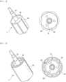
- The rotor of a general motor is now described with reference to
FIGS. 1 and 2 . A rotatingshaft 10 is installed at the center of therotor 1, the outer circumferential surface of the rotatingshaft 10 is surrounded by arotor core 20, andmagnets 30 configured to generate magnetic force to drive therotor 1 are coupled to the outer circumferential surface of therotor core 20. - Since the
magnets 30 may be separated by centrifugal force when therotor 1 is rotated, insert molding is performed on the outside of themagnets 30 in order to prevent the separation. - By the insert molding, a
mold 40 is filled through a circular mold, themold 40 is hardened over time, and therotor 1 is formed in a form surrounding themagnets 30. - However, as shown in
FIG. 3 , in the process of performing insert molding on therotor 1, the thickness of themold 40 outside themagnets 30 and the thickness of themold 40 between themagnets 30 are different, and thus the hardening speeds thereof are different from each other, with the result that deformation occurs in the thicker side of themold 40. - In other words, there occurs a phenomenon in which the
mold 40 in the portion of therotor 1 between themagnets 30 is recessed. - As shown in the drawing,
irregularities 50 are generated on the outer circumferential surface of themold 40. - Therefore, as described above, due to the deformation of the
mold 40, the quality of products deteriorates and product defects occur. - Furthermore, as described above, the
irregularities 50 generated on the outer circumferential surface of themold 40 of therotor 1 form a weak portion of therotor 1, so that the stiffness of theoverall rotor 1 is affected. Accordingly, a problem arises in that the durability of therotor 1 is deteriorated. - As a conventional technology for mitigating the above problems,
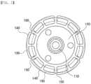
Korean Patent No. 10-1728543 - The rotor for a motor according to the above-described conventional technology includes: a
rotating shaft 110; arotor core 120 configured to surround the outer circumferential surface of the rotatingshaft 110; a plurality ofmagnets 130 disposed on the outer circumferential surface of therotor core 120 and configured to generate magnetic force; and amold 140 configured to surround themagnets 130 and therotor core 120 exposed between themagnets 130 through insert molding. Agroove 150 formed in a direction identical to the longitudinal direction of themagnets 130 is formed between each pair ofadjacent magnets 130 in themold 140. Thegrooves 150 reduce the thickness of themold 140 between themagnets 130. It is characterized in that the difference with respect to the thickness of themold 140 outside themagnets 130 is maintained within 30%. - However, the above-described conventional technology has a problem that natural demagnetization loss occurs because the cooling efficiency of the rotor is low.
- Furthermore, in the conventional technology, a problem arises in that demagnetization loss occurs due to breakage, such as magnetization of the magnet and the breaking of the edge of magnets during embedding.
- Furthermore, the PMG-type structures, such as that of the conventional technology, use only cross sections. Accordingly, they have problems in that they do not take full advantage of the Gauss magnetic nature and incur significantly high manufacturing cost because they require large magnets according to the capacity calculation.
EP3402045A1 discloses a permanent magnet module for a rotor that is configured to be mounted to a rim of the rotor and that comprises a metallic main body, a first permanent magnet component, and a first non-magnetic component.US 3221194 A discloses rotor assembly including a centrally located tubular core, circular in cross section, and which is held in assembled relation with a pair of end plates having integral hubs adapted to support bars on their outer peripheries.DE 3023743 A1 discloses a pole wheel having a magnetic system inserted in the periphery of the wheel as a preformed module.- The present invention has been conceived to overcome the above-described problems, and an object of the present invention is to provide a thin-plate module horseshoe-type PMG rotor for a motor, in which a core is divided into an iron core and a pole plate core without being molded and magnets are assembled therebetween.
- The invention refers to a thin-plate modular horseshoe-type permanent magnet rotor, for a motor, as defined in the
independent claim 1. - The following optional aspects of the invention are defined in the appended dependent claims.
- The non-conductor shaft may be made of an aluminum material.
- Each of the parts of the iron core may be configured such that an arc-shaped inner ground surface is formed to come into contact with the outer circumferential surface of the non-conductor shaft, two magnet attachment surfaces bent by 135° are formed on the surface opposite to the inner ground surface, a recessed space internally recessed is formed in both outer side ends of the magnet attachment surface, a first rail groove configured to extend in a T shape may be formed by cutting the center bent corner of the magnet attachment surfaces in a longitudinal direction, and a location guide protrusion configured to be engaged with the location guide groove of the non-conductor shaft may be formed on the inner ground surface.
- Each of the first core fixing means may include a first plate-shaped nut configured to simultaneously press and come into contact with both side ends of two opposite parts of the iron core in a longitudinal direction at a 4-divided boundary of the iron core, and a first fastening means configured to fix the first plate-shaped nut to the non-conductor shaft.
- Each of the boundary guide pins may be a plate member that has an I-shaped cross section and extends in the longitudinal direction of the iron core.
- Each of the magnets may be formed by combining a plurality of sub-unit permanent magnets.
- Each of the parts of the pole plate core may be configured to form an outer ground surface in an arc shape, to form two magnet facing surfaces, bent inward by 135°, on the inner surface of the outer ground surface, to form stop protrusions, recessed inward, on both ends of the outer ground surface, and to form a second rail groove, configured such that the inside thereof is expanded in a T-shape, by cutting the bent corners of magnet facing surfaces in a longitudinal direction.
- Each of the second core fixing means may include a second plate-shaped nut configured to be inserted into the first rail groove of the iron core in a longitudinal direction, a pressing member configured to be inserted into the stop protrusion of each of the parts of the pole plate core in the longitudinal direction, and a second fastening means configured to pass through the pressing member and to be screwed with a second plate-shaped nut to press and fix each of the parts of the pole plate core.
- A first cooling passage configured such that cooling air circulates therethrough may be formed using the recessed space of the iron core, a second cooling passage configured such that cooling air circulates therethrough may be formed in the inner center of each of the parts of the pole plate core in which the boundary guide pin is installed, a third cooling passage configured such that cooling air circulates therethrough may be formed at both ends of each of the parts of the pole plate core, and a plurality of fourth cooling passages configured to pass through the iron core in a longitudinal direction may be formed.
- The above and other objects, features, and advantages of the present invention will be more clearly understood from the following detailed description taken in conjunction with the accompanying drawings, in which:
FIG. 1 shows perspective and plan views of a rotor for a general motor, according to a conventional technology.FIG. 2 shows perspective and plan views of a state in which insert molding has been applied to the rotor for a general motor;FIG. 3 is a diagram showing a state in which the mold of the general rotor has been deformed;FIG. 4 is a perspective view showing a rotor for a motor according to a conventional technology;FIG. 5 is a diagram showing the mold of the rotor according to the conventional technology;FIG. 6 is an exploded perspective view showing a thin-plate module horseshoe-type PMG rotor for a motor according to the present invention;FIG. 7 is an assembled perspective view showing the thin-plate module horseshoe-type PMG rotor for a motor according to the present invention; andFIG. 8 is a magnetic force diagram showing the thin-plate module horseshoe-type PMG rotor for a motor according to the present invention.- An embodiment of the present invention will be described in detail below with reference to the accompanying drawings.
FIG. 6 is an exploded perspective view showing a thin-plate module horseshoe-type PMG rotor for a motor according to the present invention,FIG. 7 is an assembled perspective view showing the thin-plate module horseshoe-type PMG rotor for a motor according to the present invention, andFIG. 8 is a magnetic force diagram showing the thin-plate module horseshoe-type PMG rotor for a motor according to the present invention.- Referring to
FIGS. 6 to 8 , the thin-plate module horseshoe-type PMG rotor for a motor according to the present invention basically includes amain shaft 210, anon-conductor shaft 220, first core fixing means 240,boundary guide pins 250,magnets 260, apole plate core 270, and second core fixing means 280. - The
main shaft 210 serves as an output shaft that outputs the rotational force of the rotor to the outside, and is a round rod-shaped member fabricated in the longitudinal direction thereof. - Next, the
non-conductor shaft 220 will be described. - The
main shaft 210 is axially coupled into the cylindrical center portion of thenon-conductor shaft 220, and a plurality oflocation guide grooves 221 is formed on the outer surface of thenon-conductor shaft 220 in the longitudinal direction thereof. Thelocation guide grooves 221 are shaped in the form of slit grooves cut in the longitudinal direction thereof. - In this case, the
non-conductor shaft 220 may be made of an aluminum material. - Next, an
iron core 230 will be described. - The
iron core 230 is divided into four parts and coupled to the outer circumferential surface of thenon-conductor shaft 220. - Each of the parts of the
iron core 230 is configured such that an arc-shapedinner ground surface 231 is formed to come into contact with the outer circumferential surface of thenon-conductor shaft 220, two magnet attachment surfaces 232 bent by 135° are formed on a surface opposite to theinner ground surface 231, a recessedspace 233 internally recessed is formed in both outer side ends of themagnet attachment surface 232, afirst rail groove 234 configured to extend in a T shape is formed by cutting the center bent corner of the magnet attachment surfaces 232 in the longitudinal direction, and alocation guide protrusion 235 configured to be engaged with thelocation guide groove 221 of thenon-conductor shaft 220 is formed on theinner ground surface 231. - In this case, a plurality of
fourth cooling passages 294 may be formed to pass through theiron core 230 in the longitudinal direction. - Next, each of the first core fixing means 240 will be described.
- The first core fixing means 240 fixes both side ends of two adjacent parts of the
iron core 230 to thenon-conductor shaft 220 by pressing both side ends of two adjacent parts of theiron core 230 at a four-divided boundary of theiron core 230. - The first core fixing means 240 includes a first plate-shaped nut 241 configured to simultaneously press and come into contact with both side ends of two opposite parts of the
iron core 230 in the longitudinal direction at a 4-divided boundary of theiron core 230, and a first fastening means 242 configured to fix the first plate-shaped nut 241 to thenon-conductor shaft 220. - Next, each of the boundary guide pins 250 will be described.
- The
boundary guide pin 250 is coupled to form a longitudinal wall outside the first core fixing means 240. - The
boundary guide pin 250 is a plate member that has an I-shaped cross section and extends in the longitudinal direction of theiron core 230. - Next, the
magnets 260 will be described. - The
magnets 260 are attached in the eight directions of the outer surfaces of theiron core 230. Each of themagnets 260 may be composed of a single permanent magnet, or may be formed by combining a plurality of sub-unit permanent magnets, as disclosed in the accompanying drawings. - Next, the
pole plate core 270 will be described. - The
pole plate core 270 is divided into four parts to surround themagnets 260. - Each of the parts of the
pole plate core 270 is configured to form anouter ground surface 271 in an arc shape, to form twomagnet facing surfaces 272, bent inward by 135°, on the inner surface of theouter ground surface 271, to form stopprotrusions 273, recessed inward, on both ends of theouter ground surface 271, and to form asecond rail groove 274, configured such that the inside thereof is expanded in a T-shape, by cutting the bent corners of themagnet facing surfaces 272 in the longitudinal direction. - Next, the second core fixing means 280 will be described.
- The second core fixing means 280 fixes the
electrode plate core 270 to theiron core 230 by compressing thepole plate core 270 onto theiron core 230. - Each of the second core fixing means 280 includes a second plate-shaped
nut 281 configured to be inserted into thefirst rail groove 234 of theiron core 230 in the longitudinal direction, a pressingmember 282 configured to be inserted into thestop protrusion 273 of each of the parts of thepole plate core 270 in the longitudinal direction, and a second fastening means 283 configured to pass through thepressing member 282 and to be screwed with the second plate-shapednut 281 to press and fix each of the parts of thepole plate core 270. - According to the present invention described above, the heat generation of the rotor may be minimized by forming a plurality of cooling passages as follows:
According to the present invention, afirst cooling passage 291 configured such that cooling air circulates therethrough may be formed using the recessedspace 233 of theiron core 230, asecond cooling passage 292 configured such that cooling air circulates therethrough may be formed in the inner center of each of the parts of thepole plate core 270 in which theboundary guide pin 250 is installed, athird cooling passage 293 configured such that cooling air circulates therethrough may be formed at both ends of each of the parts of thepole plate core 270, and a plurality offourth cooling passages 294 configured to pass through theiron core 230 in the longitudinal direction may be formed. - In the above-described present invention, the core is not manufactured by molding, but is divided into the
iron core 230 and thepole plate core 270 and then themagnets 260 are assembled therebetween. Themagnets 260 may be disposed to be exposed to the surface. This method has an advantage in that there is no natural generation of demagnetization compared to the existing core assembly method. - Furthermore, according to the present invention, the plurality of cooling
passages iron core 230, themagnets 260, and thepole plate core 270 are assembled together, and thus an advantage arises in that the heat of the rotor is naturally cooled. - Furthermore, according to the present invention, the main parts of the rotor are manufactured by assembly, so that a manufacturing process may be simplified and manufacturing efficiency may be increased.
- Furthermore, according to the present invention, the main parts of the rotor may be easily disassembled and then replaced or repaired, so that advantages arise in that maintenance and repair are facilitated and management is also facilitated.
- Furthermore, according to the present invention, as shown in
FIG. 8 , the flow of magnetic force may be induced in a U-shape by disposing the boundary guide pins 250.FIG. 8 shows the flow of magnetic force as in the case where four U-shaped horseshoe magnets are formed. - Accordingly, the present invention has advantages in that there may be prevented the defect in which the corners of magnets are broken when the molding core of the conventional rotor is assembled, it is easy to handle the rotor, and the demagnetization phenomenon at the corners of the magnets may be prevented.
- Accordingly, according to the present invention, natural magnetic demagnetization loss is minimized, so that circulating magnetic force may be formed according to an increase in accelerated rotation.
- Furthermore, according to the present invention, the flat magnets (magnets embedded in a molding frame) combined to have each salient polarity through surface adhesion and close tightening without demagnetization on the surfaces of the magnets and inside the conductor core generate magnetic force inside the inner frame of the iron core as in horseshoe magnets in the manner of being cyclical and uniform in the polarity ratio.
- In addition, there is an advantage in that in order to reduce cost, several small magnets may be provided and combined and a winding salient pole-type brushless exciter functional element part is not required.
- Although an example of a 4-pole type rotor has been shown as the thin plate module horseshoe-type PMG rotor for a motor according to the present invention through the example of
FIGS. 6 to 8 above, there may be formed various types of magnetic force ranging from 2 to N poles. - According to the present invention, a combination of a various types of magnets may be possible, so that a combination of a plurality of small, rectangular, or
square magnets 260 for each capacity may be easily selected, which allows the magnets to be easily inserted and magnetized inside the molding core during combination for each dimension, thereby providing the advantage of forming large horseshoe-shaped magnetic force. - According to the above-described present invention, there may be dealt with rotors of all capacities from small to medium-large capacity rotors, mass production is easy, and manufacturing cost and prime cost are reduced.
- The embedded magnets of the present invention may be embedded in the upper left and right poles at the center of the polarity, thus conforming to the theory of electromotive force according to the electromotive force of the driving field.
- Moreover, the magnet embedding method of the present invention generates circulating magnetic force to form polarity using a negative electrode (-) and a positive electrode (+), magnet-embedded thin plate module (U-type) horseshoe-shaped magnetic force is stable because it may utilize the magnet nature of negative (-) and positive (+) polarities, and stator power obtained by the driving of the rotor is generated as the power of power generation.
- According to the above-described present invention, the core is not manufactured by molding, but is divided into the iron core and the pole plate core and then the magnets are assembled therebetween. The magnets may be disposed to be exposed to the surface. This method has no natural generation of demagnetization compared to the existing core assembly method. The number of cooling passages is naturally formed in the assembly structure of the iron core, magnets, and pole plate core, and thus the heat of the rotor may be naturally cooled. The main parts of the rotor are manufactured by assembly, and thus there are achieved the effects of simplifying the manufacturing process and improving manufacturing efficiency.
- The present invention is not limited to the specific preferred embodiments described above. Alterations and/or modifications of the described embodiments are contemplated as being alternative forms of the invention as far as they do not depart from the scope of the invention, which is defined by the appended claims.
Claims (9)
- A thin-plate modular horseshoe-type permanent magnet rotor for a motor, the rotor comprising:a main shaft (210);a magnetically non-conductive shaft (220) axially coupled to an outer circumference of the main shaft (210);an iron core (230) circumferentially divided into four equal parts and coupled to an outer circumferential surface of the magnetically non-conductive shaft (220);first core fixing means (240) for pressing and fixing both circumferential side ends of each part of the iron core (230) to the magnetically non-conductive shaft (220) along four boundaries of the iron core (230);magnets (260) attached to an outer surface of the iron core (230) in eight radial directions;a pole plate core (270) circumferentially divided into four equal parts coupled to surround the magnets (260), wherein each part of the pole plate core (270) is coupled to magnets attached in two radial directions to two adjacent parts of the iron core (230);second core fixing means for pressing and fixing both circumferential ends of each part of the pole plate core (270) to the iron core (230),boundary guide pins (250) consisting of plate members coupled to the iron core (230) and the pole plate core(270) to form a wall outside the first core fixing means (240) in an axial direction.
- The rotor of claim 1, wherein the non-conductor shaft (220) is made of an aluminum material.
- The rotor of claim 1, wherein each of parts of the iron core (230) is configured such that an arc-shaped inner ground surface (231) is formed to come into contact with an outer circumferential surface of the non-conductor shaft (220), two magnet attachment surface (232) forming an angle of 135° are formed on a surface opposite to the inner ground surface (231), a recessed space (233) internally recessed is formed in both outer side ends of the magnet attachment surface (232), a first rail groove (234) configured to extend in a T shape is formed by cutting a center bent corner of the magnet attachment surface (232) in a longitudinal direction, and a location guide protrusion (235) configured to be engaged with the location guide groove (150) of the non-conductor shaft (220) is formed on the inner ground surface.
- The rotor of claim 1, wherein each of the first core fixing means comprises a first plate-shaped nut (241) configured to simultaneously press and come into contact with both side ends of two opposite parts of the iron core (230) in a longitudinal direction at a 4-divided boundary of the iron core (230), and a first fastening means configured to fix the first plate-shaped nut (241) to the non-conductor shaft (220).
- The rotor of claim 1, wherein each of the boundary guide pin (250) is a plate member that has an I-shaped cross section and extends in a longitudinal direction of the iron core (230).
- The rotor of claim 1, wherein each of the magnets (260) is formed by combining a plurality of sub-unit permanent magnets (260).
- The rotor of claim 1, wherein each of parts of the pole plate core (270) is configured to form an outer ground surface (271) in an arc shape, to form two magnet facing surfaces, bent inward by 135°, on an inner surface of the outer ground surface (271), to form stop protrusion (273), recessed inward, on both ends of the outer ground surface (271), and to form a second rail groove (274), configured such that an inside thereof is expanded in a T-shape, by cutting bent corners of magnet facing surfaces in a longitudinal direction.
- The rotor of claim 1, wherein each of the second core fixing means comprises a second plate-shaped nut (281) configured to be inserted into the first rail groove (234) of the iron core (230) in a longitudinal direction, a pressing member (282) configured to be inserted into the stop protrusion (273) of each of the parts of the pole plate core (270) in the longitudinal direction, and a second fastening means configured to pass through the pressing member (282) and to be screwed with a second plate-shaped nut (281) to press and fix each of the parts of the pole plate core (270).
- The rotor of claim 3, wherein a first cooling passage configured such that cooling air circulates therethrough is formed using the recessed space (233) of the iron core (230), a second cooling passage configured such that cooling air circulates therethrough is formed in an inner center of each of the parts of the pole plate core (270) in which the boundary guide pin (250) is installed, a third cooling passage configured such that cooling air circulates therethrough is formed at both ends of each of the parts of the pole plate core (270), and a plurality of fourth cooling passages configured to pass through the iron core (230) in a longitudinal direction is formed.
Applications Claiming Priority (1)
| Application Number | Priority Date | Filing Date | Title |
|---|---|---|---|
| KR1020200033981AKR102135618B1 (en) | 2020-03-19 | 2020-03-19 | Pmg rotor of motor |
Publications (2)
| Publication Number | Publication Date |
|---|---|
| EP3883094A1 EP3883094A1 (en) | 2021-09-22 |
| EP3883094B1true EP3883094B1 (en) | 2024-12-04 |
Family
ID=71831797
Family Applications (1)
| Application Number | Title | Priority Date | Filing Date |
|---|---|---|---|
| EP21152667.8AActiveEP3883094B1 (en) | 2020-03-19 | 2021-01-21 | Horseshoe-type pm rotor for motor |
Country Status (2)
| Country | Link |
|---|---|
| EP (1) | EP3883094B1 (en) |
| KR (1) | KR102135618B1 (en) |
Family Cites Families (11)
| Publication number | Priority date | Publication date | Assignee | Title |
|---|---|---|---|---|
| US3221194A (en)* | 1962-01-24 | 1965-11-30 | Gen Motors Corp | Permanent magnet rotor |
| DE3023743A1 (en)* | 1980-06-25 | 1982-01-21 | Robert Bosch Gmbh, 7000 Stuttgart | Pole wheel for permanent magnet generator - has modular magnetic system formed from pole packet produced from single stamping |
| US4393320A (en)* | 1981-09-02 | 1983-07-12 | Carrier Corporation | Permanent magnet rotor |
| US4464596A (en)* | 1982-09-27 | 1984-08-07 | General Electric Company | Multi-section permanent magnet rotor |
| JP2011015500A (en)* | 2009-06-30 | 2011-01-20 | Sanyo Electric Co Ltd | Rotor of electric motor |
| KR101728543B1 (en) | 2009-12-23 | 2017-04-20 | 엘지이노텍 주식회사 | Rotor of motor |
| DE102011002327A1 (en)* | 2010-07-28 | 2012-02-02 | Joachim Sabinski | Permanent magnet rotor |
| KR101886154B1 (en)* | 2011-10-06 | 2018-08-08 | 삼성전자 주식회사 | Rotor of a motor and connecting pin for rotor |
| JP6262417B2 (en)* | 2012-07-31 | 2018-01-17 | 川崎重工業株式会社 | Magnetic field generator and superconducting rotating machine equipped with the same |
| CN106704204B (en)* | 2015-07-24 | 2020-05-08 | 浙江三花汽车零部件有限公司 | Electronic pump |
| ES2944292T3 (en)* | 2017-05-10 | 2023-06-20 | Ge Renewable Tech Wind Bv | Permanent magnet modules |
- 2020
- 2020-03-19KRKR1020200033981Apatent/KR102135618B1/enactiveActive
- 2021
- 2021-01-21EPEP21152667.8Apatent/EP3883094B1/enactiveActive
Also Published As
| Publication number | Publication date |
|---|---|
| EP3883094A1 (en) | 2021-09-22 |
| KR102135618B1 (en) | 2020-07-20 |
Similar Documents
| Publication | Publication Date | Title |
|---|---|---|
| US6967420B2 (en) | Electrical machine having a rotor specially adapted to high speeds | |
| US10879778B2 (en) | Rotor of rotating electric machine and manufacturing method of the same | |
| CN109661760B (en) | Surface magnet type motor | |
| JP3623269B2 (en) | Axial air gap motor | |
| US6259180B1 (en) | Motor including embedded permanent magnet rotor and method for making the same | |
| JP5308867B2 (en) | Rotating plate for permanent magnet rotating machine and method for manufacturing permanent magnet rotating machine | |
| US9735636B2 (en) | Rotor and dynamo-electric machine having the same | |
| US8937417B2 (en) | Rotating electric machine and wind power generation system | |
| CN111293848B (en) | Slotless brushless DC motor/actuator | |
| GB2565473A (en) | Consequent-pole rotor, electric motor, and air conditioner | |
| KR20040093669A (en) | Electrical machine, especially engines excited by permanent magnets | |
| US10756585B2 (en) | Electrical machine with rotor having permanent magnets disposed in associated radial pockets | |
| CN108696019B (en) | End plate for rotor of switched reluctance motor | |
| US20130342066A1 (en) | Rotor, dynamo-electric machine having the rotor and rotor manufacturing method | |
| US9306423B2 (en) | Motor with variable magnet flux | |
| KR101979341B1 (en) | Permanent axial flux magnet motor | |
| JP2001157393A (en) | Rotor structure for inner rotor-type motor | |
| US11973378B2 (en) | Rotor, motor, fan, air conditioner, and manufacturing method of rotor | |
| US11735967B2 (en) | Rotary electric machine with rotor having permanent magnets with concave faces between two flat portions | |
| EP3883094B1 (en) | Horseshoe-type pm rotor for motor | |
| JPH11243654A (en) | Dynamoelectric machine magnet rotor | |
| US20240258853A1 (en) | Rotor for an axial flux motor | |
| WO2011061806A1 (en) | Method of manufacturing rotor of electric motor | |
| CN110994827B (en) | Axial magnetic leakage prevention tri-rotor motor and assembly method thereof | |
| JP6685166B2 (en) | Axial gap type rotating electric machine |
Legal Events
| Date | Code | Title | Description |
|---|---|---|---|
| PUAI | Public reference made under article 153(3) epc to a published international application that has entered the european phase | Free format text:ORIGINAL CODE: 0009012 | |
| STAA | Information on the status of an ep patent application or granted ep patent | Free format text:STATUS: THE APPLICATION HAS BEEN PUBLISHED | |
| AK | Designated contracting states | Kind code of ref document:A1 Designated state(s):AL AT BE BG CH CY CZ DE DK EE ES FI FR GB GR HR HU IE IS IT LI LT LU LV MC MK MT NL NO PL PT RO RS SE SI SK SM TR | |
| STAA | Information on the status of an ep patent application or granted ep patent | Free format text:STATUS: REQUEST FOR EXAMINATION WAS MADE | |
| 17P | Request for examination filed | Effective date:20211223 | |
| RBV | Designated contracting states (corrected) | Designated state(s):AL AT BE BG CH CY CZ DE DK EE ES FI FR GB GR HR HU IE IS IT LI LT LU LV MC MK MT NL NO PL PT RO RS SE SI SK SM TR | |
| STAA | Information on the status of an ep patent application or granted ep patent | Free format text:STATUS: EXAMINATION IS IN PROGRESS | |
| 17Q | First examination report despatched | Effective date:20240313 | |
| REG | Reference to a national code | Ref country code:DE Ref legal event code:R079 Free format text:PREVIOUS MAIN CLASS: H02K0001270000 Ipc:H02K0001276000 Ref document number:602021022672 Country of ref document:DE | |
| GRAP | Despatch of communication of intention to grant a patent | Free format text:ORIGINAL CODE: EPIDOSNIGR1 | |
| STAA | Information on the status of an ep patent application or granted ep patent | Free format text:STATUS: GRANT OF PATENT IS INTENDED | |
| RIC1 | Information provided on ipc code assigned before grant | Ipc:H02K 7/00 20060101ALN20240522BHEP Ipc:H02K 1/32 20060101ALI20240522BHEP Ipc:H02K 1/30 20060101ALI20240522BHEP Ipc:H02K 1/276 20220101AFI20240522BHEP | |
| RIC1 | Information provided on ipc code assigned before grant | Ipc:H02K 7/00 20060101ALN20240528BHEP Ipc:H02K 1/32 20060101ALI20240528BHEP Ipc:H02K 1/30 20060101ALI20240528BHEP Ipc:H02K 1/276 20220101AFI20240528BHEP | |
| INTG | Intention to grant announced | Effective date:20240611 | |
| GRAS | Grant fee paid | Free format text:ORIGINAL CODE: EPIDOSNIGR3 | |
| GRAA | (expected) grant | Free format text:ORIGINAL CODE: 0009210 | |
| STAA | Information on the status of an ep patent application or granted ep patent | Free format text:STATUS: THE PATENT HAS BEEN GRANTED | |
| AK | Designated contracting states | Kind code of ref document:B1 Designated state(s):AL AT BE BG CH CY CZ DE DK EE ES FI FR GB GR HR HU IE IS IT LI LT LU LV MC MK MT NL NO PL PT RO RS SE SI SK SM TR | |
| REG | Reference to a national code | Ref country code:CH Ref legal event code:EP | |
| REG | Reference to a national code | Ref country code:DE Ref legal event code:R096 Ref document number:602021022672 Country of ref document:DE | |
| REG | Reference to a national code | Ref country code:IE Ref legal event code:FG4D | |
| REG | Reference to a national code | Ref country code:NL Ref legal event code:FP | |
| REG | Reference to a national code | Ref country code:LT Ref legal event code:MG9D | |
| PG25 | Lapsed in a contracting state [announced via postgrant information from national office to epo] | Ref country code:HR Free format text:LAPSE BECAUSE OF FAILURE TO SUBMIT A TRANSLATION OF THE DESCRIPTION OR TO PAY THE FEE WITHIN THE PRESCRIBED TIME-LIMIT Effective date:20241204 | |
| PG25 | Lapsed in a contracting state [announced via postgrant information from national office to epo] | Ref country code:FI Free format text:LAPSE BECAUSE OF FAILURE TO SUBMIT A TRANSLATION OF THE DESCRIPTION OR TO PAY THE FEE WITHIN THE PRESCRIBED TIME-LIMIT Effective date:20241204 | |
| PG25 | Lapsed in a contracting state [announced via postgrant information from national office to epo] | Ref country code:BG Free format text:LAPSE BECAUSE OF FAILURE TO SUBMIT A TRANSLATION OF THE DESCRIPTION OR TO PAY THE FEE WITHIN THE PRESCRIBED TIME-LIMIT Effective date:20241204 | |
| PG25 | Lapsed in a contracting state [announced via postgrant information from national office to epo] | Ref country code:ES Free format text:LAPSE BECAUSE OF FAILURE TO SUBMIT A TRANSLATION OF THE DESCRIPTION OR TO PAY THE FEE WITHIN THE PRESCRIBED TIME-LIMIT Effective date:20241204 | |
| PG25 | Lapsed in a contracting state [announced via postgrant information from national office to epo] | Ref country code:NO Free format text:LAPSE BECAUSE OF FAILURE TO SUBMIT A TRANSLATION OF THE DESCRIPTION OR TO PAY THE FEE WITHIN THE PRESCRIBED TIME-LIMIT Effective date:20250304 | |
| PG25 | Lapsed in a contracting state [announced via postgrant information from national office to epo] | Ref country code:LV Free format text:LAPSE BECAUSE OF FAILURE TO SUBMIT A TRANSLATION OF THE DESCRIPTION OR TO PAY THE FEE WITHIN THE PRESCRIBED TIME-LIMIT Effective date:20241204 Ref country code:GR Free format text:LAPSE BECAUSE OF FAILURE TO SUBMIT A TRANSLATION OF THE DESCRIPTION OR TO PAY THE FEE WITHIN THE PRESCRIBED TIME-LIMIT Effective date:20250305 | |
| PG25 | Lapsed in a contracting state [announced via postgrant information from national office to epo] | Ref country code:RS Free format text:LAPSE BECAUSE OF FAILURE TO SUBMIT A TRANSLATION OF THE DESCRIPTION OR TO PAY THE FEE WITHIN THE PRESCRIBED TIME-LIMIT Effective date:20250304 | |
| REG | Reference to a national code | Ref country code:AT Ref legal event code:MK05 Ref document number:1749200 Country of ref document:AT Kind code of ref document:T Effective date:20241204 | |
| PG25 | Lapsed in a contracting state [announced via postgrant information from national office to epo] | Ref country code:SM Free format text:LAPSE BECAUSE OF FAILURE TO SUBMIT A TRANSLATION OF THE DESCRIPTION OR TO PAY THE FEE WITHIN THE PRESCRIBED TIME-LIMIT Effective date:20241204 | |
| PG25 | Lapsed in a contracting state [announced via postgrant information from national office to epo] | Ref country code:PL Free format text:LAPSE BECAUSE OF FAILURE TO SUBMIT A TRANSLATION OF THE DESCRIPTION OR TO PAY THE FEE WITHIN THE PRESCRIBED TIME-LIMIT Effective date:20241204 | |
| PG25 | Lapsed in a contracting state [announced via postgrant information from national office to epo] | Ref country code:IS Free format text:LAPSE BECAUSE OF FAILURE TO SUBMIT A TRANSLATION OF THE DESCRIPTION OR TO PAY THE FEE WITHIN THE PRESCRIBED TIME-LIMIT Effective date:20250404 | |
| PG25 | Lapsed in a contracting state [announced via postgrant information from national office to epo] | Ref country code:PT Free format text:LAPSE BECAUSE OF FAILURE TO SUBMIT A TRANSLATION OF THE DESCRIPTION OR TO PAY THE FEE WITHIN THE PRESCRIBED TIME-LIMIT Effective date:20250404 | |
| PG25 | Lapsed in a contracting state [announced via postgrant information from national office to epo] | Ref country code:EE Free format text:LAPSE BECAUSE OF FAILURE TO SUBMIT A TRANSLATION OF THE DESCRIPTION OR TO PAY THE FEE WITHIN THE PRESCRIBED TIME-LIMIT Effective date:20241204 | |
| PG25 | Lapsed in a contracting state [announced via postgrant information from national office to epo] | Ref country code:RO Free format text:LAPSE BECAUSE OF FAILURE TO SUBMIT A TRANSLATION OF THE DESCRIPTION OR TO PAY THE FEE WITHIN THE PRESCRIBED TIME-LIMIT Effective date:20241204 Ref country code:AT Free format text:LAPSE BECAUSE OF FAILURE TO SUBMIT A TRANSLATION OF THE DESCRIPTION OR TO PAY THE FEE WITHIN THE PRESCRIBED TIME-LIMIT Effective date:20241204 | |
| PG25 | Lapsed in a contracting state [announced via postgrant information from national office to epo] | Ref country code:SK Free format text:LAPSE BECAUSE OF FAILURE TO SUBMIT A TRANSLATION OF THE DESCRIPTION OR TO PAY THE FEE WITHIN THE PRESCRIBED TIME-LIMIT Effective date:20241204 | |
| PG25 | Lapsed in a contracting state [announced via postgrant information from national office to epo] | Ref country code:CZ Free format text:LAPSE BECAUSE OF FAILURE TO SUBMIT A TRANSLATION OF THE DESCRIPTION OR TO PAY THE FEE WITHIN THE PRESCRIBED TIME-LIMIT Effective date:20241204 | |
| PG25 | Lapsed in a contracting state [announced via postgrant information from national office to epo] | Ref country code:IT Free format text:LAPSE BECAUSE OF FAILURE TO SUBMIT A TRANSLATION OF THE DESCRIPTION OR TO PAY THE FEE WITHIN THE PRESCRIBED TIME-LIMIT Effective date:20241204 | |
| REG | Reference to a national code | Ref country code:DE Ref legal event code:R119 Ref document number:602021022672 Country of ref document:DE | |
| PGFP | Annual fee paid to national office [announced via postgrant information from national office to epo] | Ref country code:NL Payment date:20250731 Year of fee payment:5 | |
| REG | Reference to a national code | Ref country code:CH Ref legal event code:PL | |
| PG25 | Lapsed in a contracting state [announced via postgrant information from national office to epo] | Ref country code:SE Free format text:LAPSE BECAUSE OF FAILURE TO SUBMIT A TRANSLATION OF THE DESCRIPTION OR TO PAY THE FEE WITHIN THE PRESCRIBED TIME-LIMIT Effective date:20241204 | |
| PG25 | Lapsed in a contracting state [announced via postgrant information from national office to epo] | Ref country code:LU Free format text:LAPSE BECAUSE OF NON-PAYMENT OF DUE FEES Effective date:20250121 Ref country code:MC Free format text:LAPSE BECAUSE OF FAILURE TO SUBMIT A TRANSLATION OF THE DESCRIPTION OR TO PAY THE FEE WITHIN THE PRESCRIBED TIME-LIMIT Effective date:20241204 |