EP3879268B1 - Density phase separation device - Google Patents
Density phase separation deviceDownload PDFInfo
- Publication number
- EP3879268B1 EP3879268B1EP21172549.4AEP21172549AEP3879268B1EP 3879268 B1EP3879268 B1EP 3879268B1EP 21172549 AEP21172549 AEP 21172549AEP 3879268 B1EP3879268 B1EP 3879268B1
- Authority
- EP
- European Patent Office
- Prior art keywords
- mechanical separator
- float
- separator
- hole
- collection container
- Prior art date
- Legal status (The legal status is an assumption and is not a legal conclusion. Google has not performed a legal analysis and makes no representation as to the accuracy of the status listed.)
- Active
Links
Images


Classifications
- B—PERFORMING OPERATIONS; TRANSPORTING
- B01—PHYSICAL OR CHEMICAL PROCESSES OR APPARATUS IN GENERAL
- B01D—SEPARATION
- B01D17/00—Separation of liquids, not provided for elsewhere, e.g. by thermal diffusion
- B01D17/02—Separation of non-miscible liquids
- B—PERFORMING OPERATIONS; TRANSPORTING
- B01—PHYSICAL OR CHEMICAL PROCESSES OR APPARATUS IN GENERAL
- B01L—CHEMICAL OR PHYSICAL LABORATORY APPARATUS FOR GENERAL USE
- B01L3/00—Containers or dishes for laboratory use, e.g. laboratory glassware; Droppers
- B01L3/50—Containers for the purpose of retaining a material to be analysed, e.g. test tubes
- B01L3/502—Containers for the purpose of retaining a material to be analysed, e.g. test tubes with fluid transport, e.g. in multi-compartment structures
- B01L3/5021—Test tubes specially adapted for centrifugation purposes
- B01L3/50215—Test tubes specially adapted for centrifugation purposes using a float to separate phases
- B—PERFORMING OPERATIONS; TRANSPORTING
- B01—PHYSICAL OR CHEMICAL PROCESSES OR APPARATUS IN GENERAL
- B01L—CHEMICAL OR PHYSICAL LABORATORY APPARATUS FOR GENERAL USE
- B01L3/00—Containers or dishes for laboratory use, e.g. laboratory glassware; Droppers
- B01L3/50—Containers for the purpose of retaining a material to be analysed, e.g. test tubes
- B01L3/502—Containers for the purpose of retaining a material to be analysed, e.g. test tubes with fluid transport, e.g. in multi-compartment structures
- B01L3/5021—Test tubes specially adapted for centrifugation purposes
- A—HUMAN NECESSITIES
- A61—MEDICAL OR VETERINARY SCIENCE; HYGIENE
- A61B—DIAGNOSIS; SURGERY; IDENTIFICATION
- A61B5/00—Measuring for diagnostic purposes; Identification of persons
- A61B5/15—Devices for taking samples of blood
- A—HUMAN NECESSITIES
- A61—MEDICAL OR VETERINARY SCIENCE; HYGIENE
- A61B—DIAGNOSIS; SURGERY; IDENTIFICATION
- A61B5/00—Measuring for diagnostic purposes; Identification of persons
- A61B5/15—Devices for taking samples of blood
- A61B5/157—Devices characterised by integrated means for measuring characteristics of blood
- B—PERFORMING OPERATIONS; TRANSPORTING
- B01—PHYSICAL OR CHEMICAL PROCESSES OR APPARATUS IN GENERAL
- B01D—SEPARATION
- B01D17/00—Separation of liquids, not provided for elsewhere, e.g. by thermal diffusion
- B01D17/02—Separation of non-miscible liquids
- B01D17/0217—Separation of non-miscible liquids by centrifugal force
- B—PERFORMING OPERATIONS; TRANSPORTING
- B01—PHYSICAL OR CHEMICAL PROCESSES OR APPARATUS IN GENERAL
- B01D—SEPARATION
- B01D17/00—Separation of liquids, not provided for elsewhere, e.g. by thermal diffusion
- B01D17/12—Auxiliary equipment particularly adapted for use with liquid-separating apparatus, e.g. control circuits
- B—PERFORMING OPERATIONS; TRANSPORTING
- B01—PHYSICAL OR CHEMICAL PROCESSES OR APPARATUS IN GENERAL
- B01D—SEPARATION
- B01D21/00—Separation of suspended solid particles from liquids by sedimentation
- B01D21/24—Feed or discharge mechanisms for settling tanks
- B01D21/2405—Feed mechanisms for settling tanks
- G—PHYSICS
- G01—MEASURING; TESTING
- G01N—INVESTIGATING OR ANALYSING MATERIALS BY DETERMINING THEIR CHEMICAL OR PHYSICAL PROPERTIES
- G01N1/00—Sampling; Preparing specimens for investigation
- G01N1/02—Devices for withdrawing samples
- G01N1/10—Devices for withdrawing samples in the liquid or fluent state
- G01N1/18—Devices for withdrawing samples in the liquid or fluent state with provision for splitting samples into portions
- G—PHYSICS
- G01—MEASURING; TESTING
- G01N—INVESTIGATING OR ANALYSING MATERIALS BY DETERMINING THEIR CHEMICAL OR PHYSICAL PROPERTIES
- G01N1/00—Sampling; Preparing specimens for investigation
- G01N1/28—Preparing specimens for investigation including physical details of (bio-)chemical methods covered elsewhere, e.g. G01N33/50, C12Q
- G01N1/34—Purifying; Cleaning
- G—PHYSICS
- G01—MEASURING; TESTING
- G01N—INVESTIGATING OR ANALYSING MATERIALS BY DETERMINING THEIR CHEMICAL OR PHYSICAL PROPERTIES
- G01N1/00—Sampling; Preparing specimens for investigation
- G01N1/28—Preparing specimens for investigation including physical details of (bio-)chemical methods covered elsewhere, e.g. G01N33/50, C12Q
- G01N1/40—Concentrating samples
- G01N1/4077—Concentrating samples by other techniques involving separation of suspended solids
- G—PHYSICS
- G01—MEASURING; TESTING
- G01N—INVESTIGATING OR ANALYSING MATERIALS BY DETERMINING THEIR CHEMICAL OR PHYSICAL PROPERTIES
- G01N33/00—Investigating or analysing materials by specific methods not covered by groups G01N1/00 - G01N31/00
- G01N33/48—Biological material, e.g. blood, urine; Haemocytometers
- G01N33/483—Physical analysis of biological material
- G01N33/487—Physical analysis of biological material of liquid biological material
- G01N33/49—Blood
- G01N33/491—Blood by separating the blood components
- B—PERFORMING OPERATIONS; TRANSPORTING
- B01—PHYSICAL OR CHEMICAL PROCESSES OR APPARATUS IN GENERAL
- B01D—SEPARATION
- B01D21/00—Separation of suspended solid particles from liquids by sedimentation
- B01D21/26—Separation of sediment aided by centrifugal force or centripetal force
- B01D21/262—Separation of sediment aided by centrifugal force or centripetal force by using a centrifuge
- G—PHYSICS
- G01—MEASURING; TESTING
- G01N—INVESTIGATING OR ANALYSING MATERIALS BY DETERMINING THEIR CHEMICAL OR PHYSICAL PROPERTIES
- G01N1/00—Sampling; Preparing specimens for investigation
- G01N1/28—Preparing specimens for investigation including physical details of (bio-)chemical methods covered elsewhere, e.g. G01N33/50, C12Q
- G01N1/40—Concentrating samples
- G01N1/4077—Concentrating samples by other techniques involving separation of suspended solids
- G01N2001/4083—Concentrating samples by other techniques involving separation of suspended solids sedimentation
- Y—GENERAL TAGGING OF NEW TECHNOLOGICAL DEVELOPMENTS; GENERAL TAGGING OF CROSS-SECTIONAL TECHNOLOGIES SPANNING OVER SEVERAL SECTIONS OF THE IPC; TECHNICAL SUBJECTS COVERED BY FORMER USPC CROSS-REFERENCE ART COLLECTIONS [XRACs] AND DIGESTS
- Y10—TECHNICAL SUBJECTS COVERED BY FORMER USPC
- Y10T—TECHNICAL SUBJECTS COVERED BY FORMER US CLASSIFICATION
- Y10T436/00—Chemistry: analytical and immunological testing
- Y10T436/25—Chemistry: analytical and immunological testing including sample preparation
- Y10T436/25375—Liberation or purification of sample or separation of material from a sample [e.g., filtering, centrifuging, etc.]
Definitions
- the subject inventionrelates to a device for separating higher and lower density fractions of a fluid sample. More particularly, this invention relates to a device for collecting and transporting fluid samples whereby the device and fluid sample are subjected to centrifugation in order to cause separation of the higher density fraction from the lower density fraction of the fluid sample.
- Diagnostic testsmay require separation of a patient's whole blood sample into components, such as serum or plasma (the lower density phase components), and red blood cells (the higher density phase components).
- Samples of whole bloodare typically collected by venipuncture through a cannula or needle attached to a syringe or an evacuated blood collection tube. After collection, separation of the blood into serum or plasma and red blood cells is accomplished by rotation of the syringe or tube in a centrifuge. In order to maintain the separation, a barrier must be positioned between the higher density and lower density phase components. This allows the separated components to be subsequently examined.
- a variety of separation barriershave been used in collection devices to divide the area between the higher density and lower density phases of a fluid sample.
- the most widely used devicesinclude thixotropic gel materials, such as polyester gels.
- thixotropic gel materialssuch as polyester gels.
- current polyester gel serum separation tubesrequire special manufacturing equipment to both prepare the gel and fill the tubes.
- shelf-life of the gel-based separator productis limited. Over time, globules may be released from the gel mass and enter one or both of the separated phase components.
- commercially available gel barriersmay react chemically with the analytes. Accordingly, if certain drugs are present in the blood sample when it is taken, an adverse chemical reaction with the gel interface can occur.
- an instrument probeis inserted too deeply into a collection container, then the instrument probe may become clogged if it contacts the gel.
- a mechanical barriercan be employed between the higher and lower density phases of the fluid sample.
- Conventional mechanical barriersare positioned between higher and lower density phase components utilizing elevated gravitational forces applied during centrifugation.
- conventional mechanical separatorsare typically positioned above the collected whole blood specimen prior to centrifugation. This typically requires that the mechanical separator be affixed to the underside of the tube closure in such a manner that blood fill occurs through or around the device when engaged with a blood collection set or phlebotomy needle. This attachment is required to prevent the premature movement of the separator during shipment, handling, and blood draw.
- Conventional mechanical separatorsare typically affixed to the tube closure by a mechanical interlock between the bellows component and the closure.
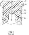
- conventional separatorsinclude a bellows 34 for providing a seal with the tube or syringe wall 38.
- the bellows 34is housed within, or in contact with a closure 32.
- the bellows 34is depressed. This creates a void 36 in which blood may pool during insertion or removal of the needle. This can result in sample pooling under the closure, device pre-launch in which the mechanical separator prematurely releases during blood collection, trapping of a significant quantity of fluid phases, such as serum and plasma, poor sample quality, and/or barrier failure under certain circumstances.
- previous mechanical separatorsare costly and complicated to manufacture due to the complicated multi-part fabrication techniques.
- Relevant prior art documentsare US 5 632 905 A , US 2004/166029 A1 , US 4 088 582 A and US 2008/023414 A1 .
- the present inventionis directed to an assembly for separating a fluid sample into a higher density and a lower density phase.
- the mechanical separator of the present inventionmay be used with a collection container, such as a tube, and is structured to move within the tube under the action of applied centrifugal force in order to separate the portions of a fluid sample.
- the tubeis a specimen collection tube including an open end, a closed end, and a sidewall extending between the open end and closed end.
- the sidewallincludes an outer surface and an inner surface and the tube further includes a closure disposed to fit in the open end of the tube with a resealable septum.
- both ends of the tubemay be open, and both ends of the tube may be sealed by elastomeric closures.
- At least one of the closures of the tubemay include a needle pierceable resealable septum.
- the mechanical separatormay be disposed within the tube at a location between the top closure and the bottom of the tube.
- the components of the separatorare dimensioned and configured to achieve an overall density for the separator that lies between the densities of the phases of a fluid sample, such as the higher and lower density phases of a blood sample.
- a mechanical separator for separating a fluid sample into first and second phases within a collection containerincludes a separator body having a through-hole defined therein.
- the through-holeis adapted for allowing fluid to pass therethrough.
- the separator bodyincludes a float, having a first density, and a ballast, having a second density greater than the first density. A portion of the float is connected to a portion of the ballast.
- the mechanical separatormay have a spheroid shape.
- the floatmay include an exterior surface and a joining surface
- the ballastmay include a contact surface connected to the joining surface of the float and an exterior surface. The exterior surface of the float and the exterior surface of the ballast taken together may form the spheroid shape.
- the floatdefines the through-hole adapted for allowing fluid to pass therethrough.
- the through-holemay have a circular cross-section. In other configurations, the through-hole may have an elliptical cross-section.
- the through-holemay be defined along a through-axis, and the float may be adapted for deformation in a direction perpendicular to the through-axis upon applied rotational force.
- the floatfurther includes a first extended tab adjacent a first opening of the through-hole and a second extended tab adjacent the second opening of the through-hole. At least a portion of the first extended tab and at least a portion of the second extended tab may be provided above and about the through-hole and extend radially outwardly from the float in a direction parallel to the through-axis of the separator body.
- the first extended tab, an upper surface of the float, and the second extended tabmay form a convex upper float surface.
- the separator bodyfurther includes an extended tab band disposed about a portion of an outer surface of the float.
- a first portion of the extended tab bandis disposed adjacent a first opening of the through-hole
- a second portion of the extended tab bandis disposed adjacent a second opening of the through-hole.
- at least one of the first portion and the second portion of the extended tab bandhave a concave downwardly-directed orientation.
- at least one of the first portion and the second portion of the extended tab bandare oriented in an outwardly-extending arcuate shape about an upper portion of at least one of the first opening and second opening of the through-hole.
- At least one of the first portion and the second portion of the extended tab bandmay extend outwardly from the float in a direction parallel to the through-axis. At least a portion of the first extended portion and at least a portion of the second extended portion of the extended tab band may have the same shape and curvature.
- the extended tab bandmay further include a joining portion disposed between and connecting the first extended portion and the second extended portion disposed on each connecting side of the separator body.
- the first extended portion and the second extended portion of the extended tab bandhave a concave downwardly-directed orientation, and the joining portions of the extended tab band have a concave upwardly-directed orientation.
- the floatmay include the extended tab band.
- the float and the extended tab bandmay be formed of TPE and the ballast is formed of PET.
- the mechanical separatormay also include an initial engagement band circumferentially disposed about the separator body.
- the initial engagement bandmay be continuous or at least partially segmented.
- the initial engagement band and the floatmay be formed of the same material.
- the initial engagement bandmay bisect at least a portion of the ballast.
- the ballastmay include a base portion and a joining structure for engaging a portion of the float.
- the joining structuremay include a plurality of arms for engaging a portion of the float, and the joining structure may provide flexure between the float and the ballast.
- at least a portion of the floatmay have a circular outer perimeter having a curved cross-section perpendicular to the through-hole.
- the floatmay include a joining structure for engaging a portion of the ballast.
- the joining structuremay include a plurality of arms for engaging a portion of the ballast, and the joining structure may provide flexure between the float and the ballast.
- a separation assemblyfor enabling separation of a fluid sample into first and second phases includes a collection container having a first end, a second end, and a sidewall extending therebetween.
- the collection containerdefines a longitudinal axis between the first end and the second end.
- the separation assemblyfurther includes a mechanical separator having a separator body having a through-hole defined therein.
- the separator bodyis adapted to transition from a first initial position in which the through-hole is oriented in an open position for allowing fluid to pass therethrough, to a second sealing position in which the through-hole is oriented in a closed position for preventing fluid from being received therethrough, upon applied rotational force.
- the separation assemblyfurther includes a closure adapted for sealing engagement with the first end of the collection container, with the mechanical separator releasably engaged with a portion of the closure.
- the mechanical separatormay be engaged with a portion of the closure in the first initial position, and the mechanical separator may be engaged with a portion of the sidewall of the collection container in the second sealing position.
- the closuremay include an engagement boss disposed within a portion of the through-hole when the separator body is in the first initial position for forming a fluid seal between a portion of the separator body and the closure.
- At least a portion of the through-hole of the mechanical separatoris oriented along the longitudinal axis of the collection container in the first initial position, and the through-hole is oriented perpendicular to the longitudinal axis of the collection container in the second sealing position. Transition of the through-hole from the open position to the closed position may coincide with rotation of the mechanical separator from the first initial position to the second sealing position.
- the mechanical separatormay sealingly engage a portion of the collection container wall in the second sealing position to prevent flow of fluid therethrough or therearound.
- the separator bodyfurther includes a first extended tab adjacent a first opening of the through-hole and a second extended tab adjacent the second opening of the through-hole.
- the first extended tab and the second extended tabmay engage a portion of the sidewall of the collection container in the second sealing position.
- the separator bodyfurther includes an extended tab band disposed about a portion of an outer surface of the float. The extended tab band may engage a portion of the sidewall of the collection container in the second sealing position, and the extended tab band may form a continuous seal with the sidewall of the collection container in the second sealing position.
- the ballastincludes a joining structure for engaging a portion of the float, and at least a portion of the float includes a circular outer perimeter having a curved cross-section perpendicular to the through-hole.
- the outer perimeter of the floatmay form a continuous seal with the sidewall of the collection container in the second sealing position.
- the floatincludes a joining structure for engaging a portion of the ballast, and at least a portion of the float includes a circular outer perimeter having a curved cross-section perpendicular to the through-hole, with the outer perimeter of the float forming a continuous seal with the sidewall of the collection container in the second sealing position.
- a separation assemblyfor enabling separation of a fluid sample into first and second phases includes a collection container having a first end, a second end, and a sidewall extending therebetween.
- the separation assemblyfurther includes a mechanical separator having a separator body having a through-hole defined therein.
- the separator bodyincludes a first sealing perimeter for providing sealing engagement with a first portion of a collection container while allowing a sample to pass through the through-hole into the collection container, and a second sealing perimeter for providing sealing engagement with a second portion of the collection container while maintaining a barrier for separation between the first and second phases.
- the separation assemblymay include a closure adapted for sealing engagement with the open end of the collection container, in which the mechanical separator is releasably engaged with a portion of the closure.
- a separation assemblyfor enabling separation of a fluid sample into first and second phases includes a collection container having an open end, a closed end, and a sidewall extending therebetween defining an interior.
- the collection containerfurther defines a longitudinal axis between the open end and the closed end.
- the separation assemblyfurther includes a closure adapted for sealing engagement with the open end of the collection container, and a post engaged with the closure and adapted for positioning within the interior of the collection container.
- the postincludes a post through-hole aligned along the longitudinal axis of the collection container.
- the separation assemblyalso includes a mechanical separator releasably engaged with the post.
- the mechanical separatorincludes a separator body having a through-hole defined therein along a through-axis, with the through-hole adapted for allowing fluid to pass therethrough.
- the separator bodyincludes a float, having a first density, and a ballast, having a second density greater than the first density. A portion of the float is connected to a portion of the ballast, and a portion of the post is received within the through-hole of the separator forming a fluid path through the post and the mechanical separator in an initial first position.
- the separator bodymay further include an initial engagement band circumferentially disposed about a portion of the separator body.
- the initial engagement band and the floatmay be formed of the same material, and the initial engagement band may bisect at least a portion of the ballast.
- the separator bodyis adapted to transition from a first initial position in which a portion of the post is disposed within the through-hole and the separator body is oriented in an open position for allowing fluid to pass therethrough, to a second sealing position in which the separator body is disengaged from the post and the through-hole is oriented in a closed position for preventing fluid from being received therethrough, upon applied rotational force. Transition of the separator body from the open position to the closed position may include an axial movement of the separator body to disengage from the post, and a rotational movement of the separator body from an initial first position to a second sealing position.
- a separation assemblyfor enabling separation of a fluid sample into first and second phases includes a collection container having an open end, a closed end, and a sidewall extending therebetween defining an interior.
- the collection containerfurther defines a longitudinal axis between the open end and the closed end.
- the separation assemblyfurther includes a closure adapted for sealing engagement with the open end of the collection container.
- the closureincludes a receiving end for positioning within the open end of the collection container, with the receiving end defining an interior cavity and including an undercut protrusion extending into the interior cavity.
- the separation assemblyfurther includes a mechanical separator releasably engaged with the closure.
- the mechanical separatorincludes a separator body having a through-hole defined therein along a through-axis, with the through-hole adapted for allowing fluid to pass therethrough.
- the separator bodyincludes a float, having a first density, and a ballast, having a second density greater than the first density, with a portion of the float connected to a portion of the ballast.
- the undercut protrusion of the closuremay be disposed within the through-hole of the separator, and at least a portion of the separator body may be disposed within the interior cavity of the closure in an initial first position.
- a collection containerin accordance with yet another embodiment of the present invention, includes a first region having an open top end and a first sidewall defining a first interior and a first exterior.
- the collection containeralso includes a second region having a closed bottom end and a second sidewall defining a second interior and a second exterior.
- the first region and the second regionmay be aligned along a longitudinal axis such that the first interior and the second interior are provided in fluid communication.
- a diameter of the first interiormay be greater than a diameter of the second interior, and at least one fluid flute may extend between the first region and the second region to allow passage of fluid therethrough from the first region to the second region.
- the first exteriorhas a 16 mm profile and the second exterior has a 13 mm profile.
- the first interiormay be dimensioned to accommodate a mechanical separator therein, and the second interior may be dimensioned to at least partially restrain a portion of the mechanical separator from passing therein absent applied rotational force.
- the first region and the second regionmay be aligned along a longitudinal axis such that the first interior and the second interior are provided in fluid communication, with a diameter of the first interior being greater than a diameter of the second interior.
- the separation assemblyfurther includes at least one fluid flute extending between the first region and the second region to allow passage of fluid therethrough from the first region to the second region.
- the separation assemblymay also include a mechanical separator having a float, having a first density, and a ballast, having a second density greater than the first density, with a portion of the float connected to a portion of the ballast. At least a portion of the mechanical separator is prevented from entering the second region in an initial first position, and the mechanical separator is transitioned into the second region upon application of rotational force to a second sealing position.
- the mechanical separatormay include a separator body having a through-hole defined therein and adapted for allowing fluid to pass therethrough.
- a separation assemblyfor enabling separation of a fluid sample into first and second phases includes a collection container having a first end, a second end, and a sidewall extending therebetween defining an interior.
- the separation assemblyfurther includes a closure adapted for sealing engagement with the open end of the collection container.
- the separation assemblyalso includes a mechanical separator releasably restrained by at least one of the closure and the sidewall of the collection container in an initial first position.
- the mechanical separatorincludes a separator body having a through-hole defined therein along a through-axis, with the through-hole adapted for allowing fluid to pass therethrough.
- the separator bodyincludes a float, having a first density, and a ballast, having a second density greater than the first density, with a portion of the float connected to a portion of the ballast.
- the separation assemblyfurther includes a carrier releasably engaged with a portion of the mechanical separator in the initial position such that, upon application of rotational force, the separator body transitions from an initial position in which fluid may pass through the through-hole, to a sealing position in which the mechanical separator prevents passage of fluid therethrough or therearound. Also upon application of rotational force, the carrier disengages from the mechanical separator.
- a separation assemblyin still a further embodiment of the present invention, includes a separation assembly including a collection container having a first end, a second end, and a sidewall extending therebetween defining an interior.
- the separation assemblyalso includes a mechanical separator including a float and a ballast and capable of movement from a first position to a sealing position. In the sealing position, a sealing perimeter is established between at least a portion of the interior and the separator, the sealing perimeter having a varying position about a portion of the interior, with the varying position defining an average sealing height.
- the mechanical separatoralso has a maximum height and a minimum height within the collection container, such that the average sealing height is less than the maximum height minus the minimum height.
- the assembly of the present inventionis advantageous over existing separation products that utilize separation gel.
- the assembly of the present inventionwill not interfere with analytes, whereas many gels interact with bodily fluids and/or analytes present within a collection container.
- the assembly of the present inventionis also advantageous over existing mechanical separators in that the separator does not require piercing of the separator body to introduce a specimen into the collection container thereby minimizing pre-launch and sample pooling under the closure.
- the structure of the present mechanical separatoralso minimizes the loss of trapped fluid phases, such as serum and plasma within the separator body.
- the assembly of the present inventiondoes not require complicated extrusion techniques during fabrication, and may optimally employ two-shot molding techniques.
- the mechanical separator of the present inventionis intended for use with a collection container for providing separation of a sample into higher and lower density phase components, as will be discussed herein.
- the present mechanical separatorcan be used to provide a separation of serum or plasma from whole blood through the use of differential buoyancy to cause a sealing area to contract when submerged in a specimen exposed to elevated gravitational forces through applied rotational force or centrifugation.
- the elevated gravitational forcescan be provided at a rate of at least 2,000 revolutions/minute, such as at least 3,400 revolutions/minute.
- the mechanical separator 40 of the present inventionincludes a separator body 41 including a float 42 and a ballast 44 connected to the float 42.
- the float 42has a first density and the ballast 44 has a second density, with the second density being greater than the first density.
- the float 42has a first buoyancy and the ballast 44 has a second buoyancy, with the first buoyancy being greater than the second buoyancy.
- the float 42may have a density of no more than about 1.020 g/cc.
- the float 42 of the mechanical separator 40may be extruded and/or molded of a resiliently deformable and self-sealable material, such as a thermoplastic elastomer (TPE).
- TPEthermoplastic elastomer
- the float 42may be extruded and/or molded of a resiliently deformable material that exhibits good sealing characteristics when contact is established with a collection container, as will be discussed herein. Maintenance of the float density within the specified tolerances is more easily obtained by using a standard material that does not require compounding with, for example, glass micro-spheres in order to reduce the material density.
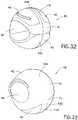
- the mechanical separator 40also includes a through-hole 46 defined therein, such as along a through-axis T of the separator body 41. As shown in FIGS. 3 , 5 , and 8 , the through-hole 46 may extend through the entire separator body 41 and includes a first opening 48 and a second opening 50 aligned along the through-axis T. In one configuration, the through-hole 46 bisects or substantially bisects the volumetric center of the separator body 41. In one embodiment, the through-hole 46 is disposed entirely within the float 42. In a further embodiment, the float 42 may further include a first extended tab 52 adjacent the first opening 48 of the through-hole 46 , and a second extended tab 54 adjacent the second opening 50 of the through-hole 46.
- the first extended tab 52 and/or the second extended tab 54may be co-formed with the float 42 , forming a portion of the float 42 itself. In another configuration, the first extended tab 52 and/or the second extended tab 54 may be separately formed and subsequently joined with the float 42.
- the first extended tab 52 and the second extended tab 54may be provided above, such as substantially above, the through-axis T of the separator body 41.
- the first extended tab 52 and the second extended tab 54may also be provided about, such as substantially about, a portion of the through-hole 46 , such as in an outwardly-extending arcuate shape about an upper portion 56 of the through-hole 46.
- the first extended tab 52 and the second extended tab 54may extend outwardly from the float 42 in a direction parallel or substantially parallel to the through axis T of the separator body 41 , such that the first extended tab 52 and the second extended tab 54 may have the same shape and curvature or substantially the same shape and curvature.
- the first extended tab 52includes a first outermost edge 68 at the upper outermost portion of a first side of the through-hole 46
- the second extended tab 54includes a second outermost edge 70 at the corresponding upper outermost portion of a second side of the through-hole 46.
- the first outermost edge 68extends outwardly a distance that is greater than the lower outermost portion 72 of the first side of the through-hole 46.
- the second outermost edge 70also extends outwardly a distance that is greater than the corresponding lower outermost portion 74 of the second side of the through-hole 46. Accordingly, the diameter D 1 of the separator body 41 taken about the first extended tab 52 and the second extended tab 54 about an upper portion of the through-hole 46 is slightly greater than the diameter D 2 of the separator body 41 taken about the lower portion of the through-hole 46 defined by the lower outermost portions 72 , 74.
- the float 42has an exterior surface 58 that is generally arcuate in shape, such as at least partially rounded or substantially rounded, and a joining surface 60 , shown in FIGS. 6 and 8 , adapted for engagement with a portion of the ballast 44.
- the ballast 44also includes an exterior surface 62 that is also generally arcuate in shape, such as at least partially rounded or substantially rounded, and a contact surface 64 , also shown in FIGS. 6 and 8 , that is adapted for joining with the joining surface 60 of the float 42.
- the exterior surface 58 of the float 42 and the exterior surface 62 of the ballast 44form a generally round exterior, such as a spheroid shape.
- spheroid shapemay include other configurations, in addition to a perfect sphere, that are aspects of the invention which may provide slightly nonuniform diameters taken through the mid-point.
- different planes taken through the float 42 and ballast 44 which bisect the midpoint of the mechanical separator 40may have varying diameter and still give rise to a generally rounded or ball-like mechanical separator 40 having a spheroid shape.
- the float 42 and the ballast 44may be separately formed and subsequently assembled.
- the float 42 and the ballast 44may be co-formed, such as co-extruded and/or co-molded, such as by a two-shot or multi-shot molding process such that both components are integrally linked together to form a complete separator body 41.
- this integral linkage between the float 42 and the ballast 44may be created by a material bond between the two components, by a mechanical interlock, or by a combination of a material bond and a mechanical interlock.
- the float 42 and the ballast 44may be linked together by a separate post-molding operation, such as adhesive, heat-staking, and/or ultrasonic welding.
- the ballast 44may include an attachment protrusion 66 which assists in the engagement of the ballast 44 and the float 42.
- the ballast 44 of the mechanical separator 40be made from a material having a higher density than the liquid intended to be separated into two phases. For example, if it is desired to separate human blood into serum and plasma, then it is desirable that the ballast 44 have a density of at least 1.029 g/cc.
- the ballast 44can be formed from mineral filled polypropylene. It is anticipated herein that both the float 42 and the ballast 44 could be formed of various other materials with sufficient biocompatibility, density stability, additive compatibility, and neutrality to analyte interactions, adsorption, and leachability.
- the mechanical separator 40includes a center of mass R that is offset from the center of volume R1 of the separator body 41.
- the volume of the separator body 41 accounted for by the float 42may be significantly greater than the volume of the separator body 41 accounted for by the ballast 44.
- the center of mass R of the separator body 41may be offset from the through-hole 46.
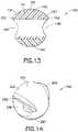
- the mechanical separator 140includes a separator body 141 having a float 142 and a ballast 144 with a through-hole 146 defined within the float 142 , as discussed above.
- the first extended tab 152 and the second extended tab 154taken with an upper portion 155 of the float 142 , form a substantially convex upper float surface 157.
- FIG. 10 and 13the first extended tab 152 and the second extended tab 154 , taken with an upper portion 155 of the float 142 , form a substantially convex upper float surface 157.
- the profile of the separator body 141is slightly off-spherical such that a diameter D 3 of the separator body extending between diagonally off-set endpoints 158 , 159 of the through-hole 146 extending along the through-axis T , is slightly larger than a diameter D 4 of the separator body extending between outermost opposing endpoints 160 , 161 tangent to the perimeter of the separator body 141 and perpendicular to the through-hole 146.
- the endpointsmay each include a thickened area of material, such as TPE.
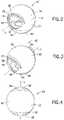
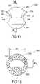
- the mechanical separator 240includes a separator body 241 having a float 242 and a ballast 244 with a through-hole 246 defined within the float 242 , as discussed above.
- the through-hole 246may have a substantially elliptical cross-section, as specifically shown in FIGS. 18-19 .
- the major axis M 1 of the ellipse, shown in FIG. 18is oriented perpendicular to the through-axis T , shown in FIG. 17 .
- the float 242may be adapted for increased elongation in the direction of the minor axis M 2 (shown in FIG. 18 ) of the ellipse upon application of rotational force, as will be discussed herein.
- the curvature of the first extended tab 252 and the curvature of the second extended tab 254are elongated to substantially mimic at least a portion of the elliptical first opening 248 and second opening 250 of the through-axis T , respectively.
- the first extended tab 252is at least partially curved in shape, such as having a convex shape, and is provided adjacent the upper portion of the first opening 248 of the through-hole 246.
- the second extended tab 254may also be at least partially curved in shape, such as having a convex shape, and may be provided adjacent the upper portion of the second opening 250 of the through-hole 246.
- the mechanical separator 240Aincludes a separator body 241A having a float 242A and a ballast 244A with a through-hole 246A defined within the float 242A , as discussed above.
- the first extended tab 252A and the second extended tab 254Amay have an elliptical profile that is substantially coincident to the diameter 243A of the separator body 241A at the edges of the through-hole 246A , and slightly offset from the diameter 243A at the apex 247A of the first and second extended tabs 252A , 254A.
- first extended tab 252A and the second extended tab 254Amay include enlarged fillets 280A positioned at the edges of the first and second extended tabs 252A , 254A adjacent the through-hole 246A to assist in the formation of a barrier against a portion of the tube wall in the sealing position, as described herein.
- the enlarged fillets 280Amay function to facilitate the shedding of cells around the mechanical separator during application of applied rotational force, as described herein.
- the enlarged fillets 280Amay also include a region of the first and second extended tabs 252A , 254A having an increased thickness and/or diameter, such as a widened taper adjacent the ends of the first and second extended tabs 252A , 254A and extending along at least a portion of the through-hole 246A.
- a mechanical separator 340 of the present inventionincludes a float 342 and a ballast 344 , and may include an elliptical interior 360 defining a substantially cylindrical through-hole 346.
- the elliptical interior 360may include a filler material 362 dimensioned to fill the elliptical interior 360 leaving a substantially cylindrical though-hole 346.
- the filler material 362may be a TPE material or other sufficiently flexible material.
- a mechanical separator 440 of the present inventionmay include an elliptical interior 460 defining an elliptical through-hole 446.
- a mechanical separator 540 of the present inventionmay include a through-hole 546 having a circular cross-section and a cylindrical shape.
- the float 542may also include a slit 548 or plurality of slits 548 , such as adjacent an interface 550 with the ballast 544. The inclusion of a slit 548 or a plurality of slits 548 defined within the float 542 may provide for increased elongation of the float 542 upon application of rotational force, as will be discussed herein.
- the mechanical separator 40 of the present inventionmay be provided as a portion of a separation assembly 80 for separating a fluid sample into first and second phases within a collection container 82 having a closure 84.
- the collection container 82may be a sample collection tube, such as a proteomics, molecular diagnostics, chemistry sample tube, blood, or other bodily fluid collection tube, coagulation sample tube, hematology sample tube, and the like.
- collection container 82is an evacuated blood collection tube.
- the collection container 82may contain additional additives as required for particular testing procedures, such as protease inhibitors, clotting agents, and the like.
- Such additivesmay be in particle or liquid form and may be sprayed onto the cylindrical sidewall 86 of the collection container 82 or located at the bottom of the collection container 82.
- the collection container 82includes a closed bottom end 88 , an open top end 90 , and a cylindrical sidewall 92 extending therebetween.
- the cylindrical sidewall 92includes an inner surface 94 with an inside diameter extending substantially uniformly from the open top end 90 to a location substantially adjacent the closed bottom end 88 along the longitudinal axis L of the collection container 82.
- the collection container 82may be made of one or more than one of the following representative materials: polypropylene, polyethylene terephthalate (PET), glass, or combinations thereof.
- the collection container 82can include a single wall or multiple wall configurations. Additionally, the collection container 82 may be constructed in any practical size for obtaining an appropriate biological sample.
- the collection container 82may be of a size similar to conventional large volume tubes, small volume tubes, or microtainer tubes, as is known in the art.
- the collection container 82may be a standard 13 ml evacuated blood collection tube, as is also known in the art.
- the open top end 90is structured to at least partially receive the closure 84 therein to form a liquid impermeable seal.
- the closure 84includes a top end 96 and a bottom end 98 structured to be at least partially received within the collection container 82. Portions of the closure 84 adjacent the top end 90 define a maximum outer diameter which exceeds the inside diameter of the collection container 82.
- the closure 84includes a pierceable resealable septum 100 penetrable by a needle cannula (not shown).
- Portions of the closure 84 extending downwardly from the bottom end 98may taper from a minor diameter which is approximately equal to, or slightly less than, the inside diameter of the collection container 82 to a major diameter that is greater than the inside diameter of the collection container 82 at the top end 96.
- the bottom end 98 of the closure 84may be urged into a portion of the collection container 82 adjacent the open top end 90.
- the inherent resiliency of closure 84can insure a sealing engagement with the inner surface 94 of the cylindrical sidewall 86 of the collection container 82.
- the closure 84can be formed of a unitarily molded elastomeric material, having any suitable size and dimensions to provide sealing engagement with the collection container 82.
- the closure 84may be at least partially surrounded by a shield, such as a Hemogard ® Shield commercially available from Becton, Dickinson and Company.
- the mechanical separator 40 of the present inventionmay be oriented within the collection container 82 in an initial position in which the through-hole 46 of the mechanical separator 40 is aligned with the open top end 90 of the collection container 82.
- the through-hole 46is adapted for allowing fluid to pass therethrough, such as from a needle cannula (not shown) which has pierced the pierceable septum 100 of the closure 84 and is provided in fluid communication with the interior of the collection container 82.
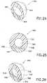
- the mechanical separator 40may also be releasably engaged with a portion of the closure 84 such that the separator body 41 may transition from the initial position, as shown in FIGS. 27-28 , to a sealing position, as shown in FIG.
- the through-hole 46is oriented in an open position for allowing fluid to pass therethrough in the direction indicated in FIG. 28 by flow arrow F.
- the initial open position of the through-hole 46is substantially aligned with the longitudinal axis L of the collection container 82.
- the mechanical separator 40upon application of rotational force, such as during centrifuge, deforms sufficiently to disengage from engagement with the closure 84 and rotate in the direction shown by directional arrow D of FIG. 29 to the sealing position in which the through-hole 46 is in a substantially closed position.
- the float 42 including the first extended tab 52 and the second extended tab 54form a sealing engagement with the inner surface 94 of the collection container 82 substantially preventing fluid from being received through the through-hole 46 or around the separator body 41.
- the through-hole 46is substantially aligned with the open top end 90 of the collection container 82 along at least a portion of the longitudinal axis L in the open position, and the through-hole 46 is substantially aligned perpendicular to the longitudinal axis in the closed position. It is noted that transition of the through-hole 46 from the open position to the closed position coincides with the rotation of the mechanical separator 40 from a first initial position to a second closed position. In another configuration, the mechanical separator 40 is engaged with a portion of the closure 84 in the first initial position, and the mechanical separator 40 is engaged with a portion of the sidewall 86 of the collection container 82 in the second sealing position. Referring again to FIG.
- the closure 84may include an engagement boss 102 for engagement with the mechanical separator 40.
- the engagement boss 102is disposed within a portion of the through-hole 46 when the separator body 41 is in the first initial position for forming a fluid seal between a portion of the separator body 41 and the closure 84.
- the mechanical separator 40may be attached to the closure 84 be means of a mechanical snap created by an undercut in the through-hole 46 which controls the release load of the mechanical separator 40.
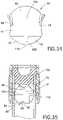
- the mechanical separator 40When the mechanical separator 40 is attached to the closure 84 , it forms a seal with the sidewall 86 of the collection container 82 along a first sealing perimeter 104 as shown in FIG. 30 .
- the first sealing perimeter 104prevents the accumulation of blood between the mechanical separator 40 and the closure 84. This reduces the formation of clots and/or fibrin strands which may disrupt function of the mechanical separator 40.
- the mechanical separator 40experiences a rotational moment while still attached to the closure 84 and, after release from the closure 84 , rotates approximately 90° to become oriented with the ballast 44 facing the bottom end 88 of the collection container 82.
- the float 42has a greater buoyancy than the ballast 44 , which generates a differential force across the mechanical separator.
- the differential forcecauses the float 42 component to elongate and contract away from the sidewall 86 of the collection container 82 , thereby reducing the effective diameter and opening a communicative pathway for the flow of fluid, such as higher and lower density phase components, past the separator body 41.
- the float 42may be adapted for deformation in a direction substantially perpendicular to the through-hole 46.
- the float 42recovers and the sealing area defined by the float 42 and the first extended tab 52 and the second extended tab 54 re-expands to seal against the inner surface 94 of the collection container along a second sealing perimeter 106 , as shown in FIG. 31 .
- the mechanical separator 40is adapted to prevent fluid from passing between or around the separator body 41 and the collection container 82 , and also prevents fluid from passing through the through-hole 46 , effectively establishing a barrier.
- the second sealing perimeter 106establishes a barrier between higher and lower density phases within the sample.
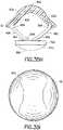
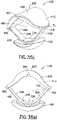
- the mechanical separator 140Aincludes a separator body 141A having a float 142A and a ballast 144A with a through-hole 146A defined within the float 142A , as discussed above.
- the float 142Amay include a partially scalloped region 150A for providing a surface to improve surface shedding of debris during use.
- a fluid samplesuch as blood
- certain blood constituentssuch as fibrin or cells, may adhere to or become otherwise trapped on the upper surface of the float 142A.
- the float 142Amay include a scalloped region 150A for increasing the surface shedding.
- the float 142Amay include opposing scalloped regions 150A , such as shown in FIG. 31B .
- the scalloped region 150Amay include any curved shape suitable to increase the surface shedding of the float, such as elliptical, oval, curved, and the like.
- the separator body 141Amay also include the first extended tab 152A and the second extended tab 154A having enlarged fillets 180A positioned at the edges of the first and second extended tabs 152A , 154A adjacent the through-hole 146A to assist in the formation of a barrier against a portion of the tube wall in the sealing position, as described herein.
- the enlarged fillets 180Amay include a region of the first and second extended tabs 152A , 154A having an increased thickness and/or diameter, such as a widened taper adjacent the ends of the first and second extended tabs 152A , 154A and extending along at least a portion of the through-hole 146A.
- the enlarged fillets 180Amay facilitate shedding of cells around the mechanical separator body 141A during application of applied rotational force, as described herein.
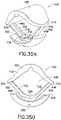
- the mechanical separator 40Dincludes a separator body 41D having a float 42D and a ballast 44D with a through-hole 46D defined within the float 42D , as discussed above.
- the separator body 41Dmay have a substantially egg-shaped outer perimeter for improving the barrier seal between the mechanical separator 40D and the sidewall of the collection container in the sealing position, such as is shown in FIGS. 29 and 68 .
- the diameter D 5 of the separator body 41Dmay be less than the diameter D 6 of the separator body 41D , specifically the float 42D as shown in FIG. 31D , taken across the float 42D in the direction perpendicular to the through-axis T axis of the through hole 46D , as shown in FIG. 31F .
- the diameter D 7 of the separator body 41Dspecifically the float 42D as shown in FIG.
- the diameter D 8 of the ballast 44D taken across the ballast 44D along the through-axis T axis of the through-hole 46Dmay be less than any of the diameters D 5 , D 6 , or D 7 of the separator body 41D.
- a float 42D having an increased diameter with respect to the ballast 44Dmay provide for a mechanical separator 40D having an increased volume of lower density material, such as TPE, for displacing against a sealing surface as described herein.
- This embodimentmay also include an extended tab band, as discussed below with respect to FIGS. 35A-35E , and/or an initial engagement band, as discussed below with respect to FIGS. 33-35 .
- the mechanical separator 40may further include an initial engagement band 116 circumferentially disposed about the separator body 41.
- the initial engagement band 116may be disposed about the separator body 41 in a direction substantially perpendicular to the through-hole 46.
- the initial engagement band 116may be continuously provided about the separator body 41 , or may optionally be provided in segments about the separator body 41.
- the float 42 and the initial engagement band 116may be formed from the same material, such as TPE.
- the initial engagement band 116may be provided such that a first portion 42A of the float 42 forms the initial engagement band 116 , and a second portion 42B substantially bisects the ballast 44.
- the initial engagement band 116provides an interference engagement between the separator body 41 and the inner surface 94 of the collection container 82.
- a first sealing perimeter 104 about the separator body 41is inline with the initial engagement band 116. This first sealing perimeter 104 assists in maintaining the separator body 41 in proper alignment with the open top end 90 of the collection container 82 , such that fluid entering the collection container 82 from a cannula (not shown) disposed through the pierceable septum 100 will pass through the first opening 48 of the separator body 41 , through the through-hole 46 , and out the second opening 50.
- the mechanical separator 40Cincludes a separator body 41C having a float 42C and a ballast 44C.
- the separator body 41Cincludes a through-hole 46C defined therein, such as defined entirely within the float 42C.
- the float 42Cmay include an extended tab band 50C disposed about an outer surface 52C of the float 42C.
- the extended tab band 50Cmay include a first extended portion 54C adjacent a first opening 56C of the through-hole 46C , and a second extended portion 58C adjacent the second opening 60C of the through-hole 46C.
- first extended portion 54C and the second extended portion 58Cmay be provided substantially adjacent to at least a portion of the first opening 56C and the second opening 60C , respectively.
- the first extended portion 54C and the second extended portion 58Cmay each have a generally concave downwardly-directed orientation.
- the first extended portion 54C and the second extended portion 58Cmay also be provided substantially about a portion of the through-hole 46C , such as in an outwardly-extending arcuate shape about an upper portion of the through-hole 46C.
- a portion of the first extended portion 54C and a portion of the second extended portion 58Cmay extend outwardly from the float 42C in a direction substantially parallel to the through axis T A of the separator body 41C , such that the first extended portion 54C and the second extended portion 58C may have substantially the same shape and curvature.
- the extended tab band 50Cmay also include joining portions 62C disposed between and connecting the first extended portion 54C and the second extended portion 58C on both sides of the separator body 41C.
- the joining portions 62Cmay each have a generally concave upwardly-directed orientation.
- the joining portions 62C , the first extended portion 54C , and the second extended portion 58Care continuous therewith, forming a generally "rope-like" appearance wrapped around a portion of the float 42C.
- the joining portions 62C , the first extended portion 54C , and the second extended portion 58Cform a continuous sine function shape about a portion of the outer surface 52C of the float 42C.
- the extended tab band 50Cmay be co-formed with the float 42C , forming a portion of the float 42C itself.
- the extended tab band 50Cmay be separately formed and subsequently joined with the float 42C.
- both the float 42C and the extended tab band 50Care made of a lower density material, such as TPE, and the ballast 44C may be formed of a higher density material, such as PET.
- the joining portions 62Cmay each have approximately the same thickness T J .
- the first extended portion 54C and the second extended portion 58Cmay also have approximately the same thickness T J .
- the cross-section of the extended tab band 50Cmay have any suitable sealing shape such as rounded, squared, ribbed, or the like. It is also contemplated herein, that multiple extended tab bands 50C may be disposed about the outer surface 52C of the float 42C. Referring to FIGS.
- the first extended portion 54C and the second extended portion 58Cmay include a thickened shelf region, 54C1 and 58C1 , respectively, defining a generally spline or saddle shape with the upper portion 64C of the float 42C.
- the upper portion 64C of the float 42C and the extended tab band 50Cmay be particularly configured to maximize the surface shedding of debris during use.
- certain blood constituents, such as fibrin or cellsmay adhere to or become otherwise trapped on the upper surface of the float 42C.
- the specific shaping of the extended tab band 50Cis intended to minimize the trapping of debris during use.
- the extended tab band 50Cmay include a first extended portion 54C , a second extended portion 58C , and joining portions 62C connecting the first extended portion 54C and the second extended portion 58C on both sides of the float 42C so as to form a continuous structure about the outer surface 52C of the float 42C.
- the thickened shelf region 54C1 of the first extended portion 54C and the thickened shelf region 58C1 of the second extended portion 58Chave a truncated profile 54C2 and 58C2 , respectively, to improve surface shedding of debris during use and to provide additional structural support to the first extended portion 54C and the second extended portion 58C during sealing with a collection container (not shown) in the sealing position.
- the extended tab band 50CWhen the mechanical separator 40C of the present embodiment is in use, the extended tab band 50C provides a robust sealing surface against a portion of the collection container wall (not shown), similar to the seal defined by the first extended tab and the second extended tab described above with reference to FIGS. 1-8 . In certain embodiments, the extended tab band 50C may provide additional sealing and minimize leakage between the mechanical separator 40C and the collection container. In addition, in the configurations in which the float 42C is formed of TPE, the extended tab band 50C provides a mechanism for enhanced sealing in that TPE does not appreciably deform under conventional applied rotational forces but rather displaces to another location.
- the location of the arcuate extended tab band 50C about an outer surface 52C of the float 42Callows for the TPE to displace uniformly against a sidewall of the collection container in a sealing position, as described herein.
- the sealing surface of the mechanical separator 40Cmay be located at various heights about the outer surface 52C of the float 42C corresponding to the location of the extended tab band 50C.
- the mechanical separator 40C having an extended tab band 50Cmay be suitable for use in collection containers having a tilted orientation due to the enhanced sealing between the extended tab band 50C and the collection container (as described above) in the sealing position. It is also intended herein that the mechanical separator 40C may include an initial engagement band 116 , as similarly described with reference to FIG. 35 above.
- the mechanical separator 40Aincludes a separator body 41A having a float 42A and a ballast 44A.
- the separator body 41Aincludes a through-hole 46A defined therein.
- the ballast 44Amay include a base portion 52A and a joining structure 48A , such as a plurality of arms 50A for engaging a portion of the float 42A.
- the ballast 44Aspecifically the joining structure 48A , may be provided in permanent engagement with a portion of the float 42A , such as by co-molding, two-shot molding, welding, or other adhesive joining means.
- the float 42Amay be formed of a lower density material, such as TPE, and the ballast 44A may be formed of a higher density material, such as PET.
- the mechanical separator 40Amay be dimensioned such that the overall density of the separator body 41A is between the density of higher and lower density constituents of a blood sample, such as serum and red blood cells.
- the overall density of the separator body 41Ais 1.45 g/cm 3 .
- the ballast 44Amay include a base portion 52A having a contact surface 54A and a joining surface 56A.
- the contact surface 54Amay include an at least partially curved surface 58A corresponding to an inner curvature of a collection container (not shown).
- the joining surface 56Amay include an attachment between the base portion 52A and the joining structure 48A.
- the joining surface 56A and the joining structure 48Aare co-formed.
- the joining surface 56A and the joining structure 48Aare separately formed and subsequently provided in permanent attachment through mechanical or adhesive locking means.
- the joining structure 48Amay include a first end 60A for engaging the base portion 52A of the ballast 44A and a second end 62A for engaging a portion of the float 42A.
- the top view of the float 42Amay have a substantially circular outer perimeter P O , as shown in FIG. 35I , and the float 42A may have a substantially curved cross-sectional side view, such as a substantially concave down cross-section as shown in FIG. 35H .
- the float 42Amay have a substantially concave down cross-section adjacent an apex 64A of the float 42A , and a slight concave upward curvature adjacent the perimeter P O of the float 42A , such as at a location at which the second end 62A of the joining structure 48A is attached to the float 42A.
- the second end 62A of the joining structure 48Ais molded first and the float 42A is subsequently molded onto the second end 62A of the joining structure 48A to form a bond therewith.
- the second end 62A of the joining structure 48Ais inserted within, or provided adjacent to, a portion of the float 42A and subsequently bonded or otherwise adhered thereto.
- the joining structure 48Amay provide flexure between the float 42A and the base portion 52A.
- the flexuremay be provided by at least one of the attachment between the first end 60A of the joining structure 48A and the base portion 52A , the attachment between the second end 62A of the joining structure 48A and the float 42A , and the pivot points 68A of the joining structure 48A.
- the mechanical separator 40Amay be provided within a collection container 100A , such as adjacent an upper end 102A of the collection container 100A in an initial position.
- the mechanical separator 40Amay be provided in engagement with a portion of a stopper 104A , such that a portion of the stopper 104A extends through the through-hole 46A of the mechanical separator 40A , as described elsewhere herein.
- the mechanical separator 40Amay be provided such that a portion of the float 42A and a portion of the base portion 52A of the ballast 44A engage an inner surface of the collection container 100A to restrain the mechanical separator 40A within the upper end 102A of the collection container 100A such that the through-hole 46A of the mechanical separator 40A is aligned with the longitudinal axis L A of the collection container 100A.
- a fluid specimen 108Asuch as blood
- the collection container 100Asuch as through the stopper 104A and aligned with through-hole 46A of the mechanical separator 40A when the mechanical separator 40A is oriented in the initial position as shown by reference character A.
- the float 42Aflexes and initiates a flexure between the float 42A and the ballast 44A , as described above.
- the resulting flexuredeforms the through-hole 46A and the mechanical separator 40A disengages from the stopper 104A and begins to rotate in the direction shown by arrow R , as shown by reference character B.
- the float 42Abegins to orient in an upward direction and the ballast 44A simultaneously begins to orient in a downwards direction, as shown by reference character C.
- the ballast 44Apulls in a downwards direction and the float 42A flexes away from the sidewall 110A of the collection container, as shown by reference character D.
- the float 42Ais deformed to allow for the passage of higher and lower density phase constituents between the float 42A and the sidewall 110A of the collection container 100A. This allows for separation of the higher and lower density phase constituents within the fluid sample 108A , as well as for the separation of higher and lower density phase constituents within the fluid sample 108A present within the through-hole 46A of the mechanical separator 40A.
- the mechanical separator 40Abecomes oriented between the separated higher density phase 112A and the separated lower density phase 114A in a sealing position.
- the flexure between the float 42A and the ballast 44Aceases, causing the float 42A to return to its initial position, as shown in FIG. 351 , thereby forming a seal between the outer perimeter P O and the interior circumference of the sidewall 110A of the collection container 100A.
- the float 42Ahas an outer perimeter P O having an outer circumference that is at least slightly larger than the interior circumference of the sidewall 110A of the collection container 100A , thereby forming a robust seal therebetween.
- a sealing perimeteris established along the outer perimeter P O between at least a portion of the interior circumference of the sidewall 110A and the mechanical separator 40A.
- the sealing perimeter along the outer perimeter P Ohas a varying position about the interior circumference of the sidewall 110A as measured from the closed bottom end 113A of the collection container 100A.
- the sealing perimeter along the outer perimeter P Oincludes various sealing heights at each localized sealing location, S 1 , S 2 , S 3 , etc. corresponding to the overall height of the seal between the mechanical separator 40A , specifically, the float 42A , and the sidewall 110A.
- the sealing perimeteraccordingly has a height which varies slightly at each localized sealing location S 1 , S 2 , S 3 , etc.
- the mechanical separator 40Aalso has a maximum height H Max and a minimum height H Min within the collection container.
- the maximum height H Maxcorresponds to the distance between the highest seal point along the outer perimeter P O and the closed bottom end 113A of the collection container 100A.
- the minimum height H Mincorresponds to the lowest seal point along the outer perimeter P O and the closed bottom end 113A of the collection container 100A.
- the average sealing height H Avgis less than the difference between the maximum seal height H Max and the minimum seal height H Min , i.e., H Avg ⁇ H Max - H Min
- the mechanical separator 40Bincludes a separator body 41B having a float 42B and a ballast 44B.
- the separator body 41Bincludes a through-hole 46B defined therein.
- the float 42Bmay include a joining structure 48B , such as a plurality of arms 50B for engaging a portion of the ballast 44B.
- the joining structure 48Bmay be provided in permanent engagement with a portion of the ballast 44B , such as by co-molding, two-shot molding, welding, or other adhesive joining means.
- the joining structure 48Bmay exhibit increased flexibility allowing for easier transition from an initial position to a sealing position, as described herein.
- the float 42Bmay include a cut-out 60B within the float 42B.
- the cut-out 60Bmay be positioned at the apex 62B of the float 42B and does not extend into the outer perimeter P O .
- the cut-out 60Bmay provide for increased flexibility to allow passage of higher and lower density phase constituents thereby during use, such as shown in FIG. 35J with reference to reference character E.
- the joining structure 48Bmay include an opening 64B therein adapted to allow a portion of the ballast 44B to pass therethrough and be secured therein, such as by way of a mechanical interlock.
- the joining structure 48Bincludes a continuous arm 50B connected to the float 42B at a first end 68B and a second end 70B.
- the joining structure 48Bmay include an opening 64B having a locking portion 72B of the ballast 44B extending therethrough.
- the opening 64Bmay be disposed within the continuous arm 50B at a location opposed from the apex 62B of the float 42B.
- the ballast 44Bsuch as the locking portion 72B
- the float 42Bmay be provided in permanent engagement so as to minimize separation of the float 42B and the ballast 44B.
- the mechanical separator 40Bincludes a separator body 41B having a float 42B and a ballast 44B.
- the separator body 41Bincludes a through-hole 46B defined therein.
- the float 42Bmay include a joining structure 48B , such as a plurality of arms 50B for engaging a portion of the ballast 44B.
- the joining structure 48Bmay include a continuous arm 50B connected to the float 42B at a first end 68B and a second end 70B.
- the joining structure 48Bmay include an opening 64B having a locking portion 72B of the ballast 44B extending therethrough in permanent engagement so as to minimize separation of the float 42B and the ballast 44B.
- the ballast 44Bmay also include a support structure 74B adjacent and connected to the joining structure 48B of the float 42B.
- the support structure 74B of the ballast 44Bmay be co-formed or otherwise permanently engaged with the joining structure 48B of the float 42B.
- the joining structure 48Bmay define a recess adapted to at least partially surround the support structure 74B.
- the support structure 74B and the joining structure 48Ballow the float 42B and ballast 44B to at least partially flex with respect to each other, as described herein.
- a ballast cut-out 80Bmay be provided within the base portion 52B to lessen shrinkage of the ballast 44B during formation.
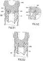
- the through-hole of the mechanical separator of the present inventionhas been shown herein as a straight bore having a spherical or elliptical cross-section, it is also contemplated herein that the through-hole 546 , as shown in FIGS. 36-37 , may define a serpentine or circuitous path for receiving liquid therethrough.
- the mechanical separator 540includes a through-hole 546 having a first opening 549 and a second opening 551 that are offset with respect to each other.
- the first opening 549 and the second opening 551may be offset, such as at 60° or 90° angles with respect to each other.
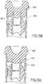
- the first opening 549is aligned with the top open end 590 of the collection container 582 , represented herein in section.
- Fluidis directed through the through-hole 546 in the direction as shown by directional arrow R.
- at least one surface of the second opening 551contacts the sidewall of the collection container 582 , while another surface of the second opening 551 remains free within the interior of the collection container 582. Accordingly, a gap is provided between the sidewall of the collection container 582 and the second opening 551 of the through-hole 546 to allow fluid to exit the through-hole 546 and pass into the interior of the collection container 582.
- both the first opening 549 and the second opening 551 of the through-hole 546are provided out of alignment with the top open end 590 of the collection container 582 and are adapted such that fluid is not directed into the through-hole 546.
- a second sealing perimeter 595is also established about the mechanical separator 540 such that fluid cannot pass between the mechanical separator 540 and the collection container 582 or through the through-hole 546 of the mechanical separator 540 , effectively establishing a barrier.
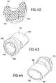
- the mechanical separator 640may include a float 642 and a ballast 644 with a third section 643 joining the float 642 and the ballast 644. It is contemplated herein, that in this configuration, both the float 642 and the ballast 644 may be made of a substantially rigid material with the float 642 having a density that is less than the density of the ballast 644. In order to provide for an elongation between these components, the third section 643 formed of a flexible material, such as TPE, may be provided therebetween.
- TPEa flexible material
- the third section 643elongates, as shown in FIG. 39 , in a manner similarly described with respect to the elongation of the float above.
- higher and lower density phases of a fluidmay pass adjacent the fluid passage surfaces 645 , as shown in FIG. 39 as in a direction extending into the page.
- the separator body 41may include a center of mass R that is offset from the through-axis T , shown in FIG. 2 , of the separator body 41.
- the mechanical separator 40is transitionable from a first position (such as shown in FIGS. 40-41 ) in which the mechanical separator 40 is engaged with a portion of the closure 84 (shown in FIG. 41 ) or a portion of the sidewall 86 of the collection container 82 (shown in FIG. 40 ) and the center of mass R is oriented on a first side S 1 of the longitudinal axis L of the collection container 82 , to a second position, such as shown in FIG.
- the mechanical separator 40is disengaged from the closure or initial engagement position with the collection container, and the center of mass R is oriented across the longitudinal axis L of the collection container 82.
- the float 42 of the mechanical separator 40must deform in a direction substantially perpendicular to the through-axis T of the separator body 41 in order to allow for transition of the mechanical separator 40 from the initial first position to the second sealing position.
- the higher and lower density phases of the specimenmay pass between the mechanical separator 40 , specifically the elongated float 42 , and the sidewall 86 of the collection container 82 in which the mechanical separator is in an intermediate position. From the intermediate position, the mechanical separator may subsequently transition to the sealing position, in which a portion of the float 42 forms a sealing engagement with a portion of the interior of the collection container, upon termination of applied rotational force.
- the mechanical separator of the present inventionmay be considered to transition between three phases of operation: the initial phase in which a specimen is provided through the through-hole of the separator body; the intermediate phase in which the separator has disengaged from the initial position and the float 42 is elongated to allow passage of higher and lower density phases thereby; and the sealing position in which the float 42 forms a barrier with a portion of the collection container.
- the mechanical separatormay be considered as "open-open-closed” wherein an "open” phase is defined as a state in which the mechanical separator does not form a sealing barrier with the collection container preventing the passage of fluid therethrough and therearound.
- a "closed” phaseis defined as a state in which mechanical separator 40 does form a sealing barrier with the collection container preventing the passage of fluid therethrough and therearound.
- the mechanical separator of the present inventionis also intended for use with various closure arrangements in the initial phase.
- the mechanical separator 40may be maintained in the initial position by the interference between the float 42 and the initial engagement band 116 and the sidewall 86 of the collection container 82. In this configuration, the mechanical separator 40 is not restrained by any portion of the closure 84.
- the separation assemblyincludes a closure 84 and a post 180 engaged within a recess 181 of the closure 84.
- the post 180may include a separator receiving end 182 and a closure engagement end 183.
- the closure engagement end 183may be adapted for positioning within the recess 181 of the closure 84 and may optionally include at least one barb 184 for securing the post 180 within the closure 84.
- the separator receiving end 182may have any suitable profile such that it may be at least partially disposed within the through-hole 46 of the separator body 41. In one embodiment, the separator receiving end 182 has a substantially circular cross-section.
- the separator receiving end 182has a substantially elliptical cross-section.
- the separator receiving end 182is dimensioned to snugly fit within the through-hole 46 to provide a releaseable engagement with the mechanical separator 40.
- the post 180is also adapted for positioning within the interior of the collection container 82 and includes a post through-hole 186 aligned along the longitudinal axis of the collection container 82.
- a fluid pathis formed between the through-hole 46 of the mechanical separator 40 and the post through-hole 186 of the post 180. This effectively forms a "sealed" fluid path for the direction of the fluid sample into the collection container 82.
- the mechanical separatorUpon application of rotational force, the mechanical separator experiences a slight longitudinal movement prior to the axial rotation as the mechanical separator is pulled downward off the post 180 during applied rotation.
- an alternative separation assemblyincluding a collection container 782 having a first region 783 having an open top end 784 and a first sidewall 785 defining a first interior 786 and a first exterior 787.
- the collection container 782also includes a second region 788 having a closed bottom end 789 and a second sidewall 790 defining a second interior 791 and a second exterior 792.
- the first region 783 and the second region 788are aligned along a longitudinal axis L A such that the first interior 786 and the second interior 791 are provided in fluid communication.
- the first interior 786includes a first diameter D F and the second interior 791 includes a second diameter D S , with the first diameter D F being greater than the second diameter D S .
- the collection container 782also includes at least one fluid flute 793 extending between the first region 783 and the second region 788 to allow passage of fluid therethrough from the first region 783 to the second region 788.
- the first exterior 787 of the first region 783may have a profile that corresponds to a 16 mm collection tube
- the second exterior 792 of the second region 788may have a profile that corresponds to a 13 mm collection tube.
- the first interior 786 of the first region 783may be dimensioned to accommodate a mechanical separator 40 therein in any of the configurations described herein.
- the second interior 791is dimensioned to at least partially restrain a portion of the mechanical separator 40 from passing therein in the initial position and absent applied rotational force.
- the float portion 42 of the mechanical separator 40may elongate thereby decreasing the effective diameter of the mechanical separator 40 and allowing passage of the mechanical separator into the second interior 791.
- the orientation of the through-hole 46 of the mechanical separator 40is irrelevant as the introduction of fluid sample into the collection container 782 occurs around the separator body 41 as opposed to through the through-hole 46.
- fluidis introduced into the collection container 782 into the first interior 786 and around the mechanical separator 40.
- the samplethen passes into the second interior 791 by way of the fluid flutes 793. Accordingly, the initial orientation of the mechanical separator 40 is irrelevant to the function of the separator in this embodiment.
- a mechanical separatoras described herein, may be used with a collection container 782A having a slight taper along a portion of the sidewall 783A extending between an open top end 784A and a closed bottom end 785A.
- the collection container 782Aincludes a first region indicator section A of FIG. 46A .
- First region indicator section Ais disposed along a portion of the sidewall 783A at a distance 786A from the open top end 784A.
- the collection container 782Amay also include a second region indicator section B of FIG. 46A .
- Second region indicator section Bis disposed along a portion of the sidewall 783 at a distance 788A from the open top end 784A.
- the region defined between the first region indicator section A and the second region indicator Bmay have substantially no taper.
- the region defined between the first region indicator section A and the second region indicator Bmay have substantially may have a slight inward taper.
- the region defined between the first region indicator section A and the second region indicator Bmay be about the expected separation transition between the separated higher and lower density phases of a liquid to be separated.
- the separation assemblyincludes a closure 850 adapted for sealing engagement with the collection container 852.
- the closure 850includes a receiving end 842 for positioning within the open end 853 of the collection container 852.
- the receiving end 842defines an interior cavity 854 and includes an undercut protrusion 855 extending into the interior cavity 854.
- the undercut protrusion 855 of the closure 850is at least partially disposed within the through-hole 46 of the mechanical separator 40 in the initial position. Also in the initial position, at least a portion of the separator body 41 is disposed within the interior cavity 854.
- the positioning of the mechanical separator 40 within the interior cavity 854ensures that the mechanical separator 40 remains captured in the closure 850 during assembly of the closure 850 with the collection container 852.
- This configurationmay be utilized with the collection container having a first region and a second region, as described above.
- the float 42 of the mechanical separator 40elongates allowing the mechanical separator 40 to disengage from the closure 850.
- the mechanical separator 40may include an angled engagement boss 900 disposed within the through-hole 46 in the initial position.
- the mechanical separator 40may include a substantially cylindrical engagement boss 901 disposed within the through-hole 46 in the initial position.
- a flanking portion 902 of the closure 903may be provided adjacent an exterior surface 904 of the mechanical separator 40 adjacent the first opening 905 for further securing the mechanical separator 40 with the closure 903 and establishing a "sealed" fluid path into the collection container 906 therethrough.
- a sealant 907may be provided adjacent the flanking portion 902 , as described above, for further securing the mechanical separator 40 and the closure 903.
- the sealant 907may be sufficiently tacky to retain the mechanical separator 40 in place in the initial position, yet weak enough to permit release of the mechanical separator 40 from the closure 903 upon application of rotational force.
- the closure 910may include at least one, such as two, depending arms 911 for engagement with the mechanical separator 40.
- each depending arm 911includes a contact protrusion 912 for engaging a portion of the mechanical separator 40 within the through-hole 46 in the initial position. The interference between the contact protrusion 912 and the mechanical separator 40 may be sufficient to restrain the mechanical separator 40 with the closure 910 in the initial position, yet allow for disengagement of the mechanical separator 40 from the closure 910 upon application of rotational force.
- the closure 915may include a molding insert 916 having a wedging basket 917 for further securing the molding insert 916 with the closure 915.
- the molding insert 916may include a separator receiving end 918 for engaging the mechanical separator 40 through the through-hole 46 , and a closure engagement end 919 , as described above.
- another molding insert 920may include at least one barb 921 for further securing the molding insert 920 with the closure 922.
- yet another molding insert 930may include at least one protrusion 931 for securing the molding insert 930 with the closure 932.
- the separation assemblies described hereinmay also include a carrier 650 releasably engaged with a portion of the mechanical separator 40 in the initial position.
- the carrier 650disengages from the mechanical separator 40 upon application of rotational force and enters the fluid phase disposed below the mechanical separator 40 for the purpose of preventing clots or fibrin strands from interfering with the operation of the mechanical separator 40.
- the carrier 650may include a closure engagement portion 651 for releasable engagement with a portion of the closure 652 , and a depending portion 653 for releasable engagement with a portion of the mechanical separator 40 , such as through the through-hole 46.
- the carrier 650may include a closure engagement portion 651 having a plurality of flanges 654.
- the carrier 650may also include a bowed separator engagement portion 655 for engaging a portion of the mechanical separator 40 , such as within the through-hole 46.
- the mechanical separator 40disengages from the initial position and rotates as described herein.
- the bowed separator engagement portion 655contracts and allows the mechanical separator 40 to separate from the carrier 650.
- the carrier 650may also be releasably connected to the mechanical separator 40 in a direction opposed from the closure 660.
- the carrier 650may optionally consist of a dissolvable material which diffuses into the sample when contact is made, as shown in FIG. 68 .
- the mechanical separator of the present inventiondoes not require penetration by a needle cannula in order to permit entry of a fluid sample into a collection container.
- an applied rotational forcesuch as centrifugation
- the respective phases of the specimensuch as blood
- the applied rotational forcewill urge the ballast of the mechanical separator toward the closed bottom end and the float toward the top end of the collection container. This movement of the ballast will generate a longitudinal deformation of the float.
- the floatwill become longer and narrower and will be spaced concentrically inward from the inner surface of the cylindrical sidewall of the collection container. Accordingly, lighter phase components of the blood will be able to slide past the float and travel upwards, and likewise, heavier phase components of the blood will be able to slide past the float and travel downwards.
- the mechanical separator of the present inventiontypically has an overall density between the densities of the separated phases of the blood. Consequently, the mechanical separator will stabilize in a position within the collection container such that the heavier phase components will be located between the mechanical separator and the closed bottom end of the collection container, while the lighter phase components will be located between the mechanical separator and the top end of the collection container.
- the centrifugewill be stopped and the float will resiliently return to its unbiased state and into sealing engagement with the interior of the cylindrical sidewall of the collection container.
- the formed liquid phasesmay then be accessed separately for analysis.
- the assembled mechanical separator of the present inventionmay be scaled to fit within a 13 mm collection tube.
- the mechanical separator of the present inventionminimizes device pre-launch and eliminates the need for cannula puncture which substantially eliminates sample pooling under the closure. Additionally, the reduced clearance of the mechanical separator minimizes the loss of trapped fluid phases, such as serum and plasma.
Landscapes
- Health & Medical Sciences (AREA)
- Life Sciences & Earth Sciences (AREA)
- Chemical & Material Sciences (AREA)
- Physics & Mathematics (AREA)
- Engineering & Computer Science (AREA)
- General Health & Medical Sciences (AREA)
- Hematology (AREA)
- Analytical Chemistry (AREA)
- Biomedical Technology (AREA)
- Chemical Kinetics & Catalysis (AREA)
- Pathology (AREA)
- Immunology (AREA)
- General Physics & Mathematics (AREA)
- Biochemistry (AREA)
- Molecular Biology (AREA)
- Clinical Laboratory Science (AREA)
- Biophysics (AREA)
- Thermal Sciences (AREA)
- Food Science & Technology (AREA)
- Medicinal Chemistry (AREA)
- Urology & Nephrology (AREA)
- Public Health (AREA)
- Veterinary Medicine (AREA)
- Heart & Thoracic Surgery (AREA)
- Medical Informatics (AREA)
- Surgery (AREA)
- Animal Behavior & Ethology (AREA)
- Ecology (AREA)
- Hydrology & Water Resources (AREA)
- Centrifugal Separators (AREA)
- Sampling And Sample Adjustment (AREA)
- Investigating Or Analysing Biological Materials (AREA)
- External Artificial Organs (AREA)
- Vehicle Body Suspensions (AREA)
- Hard Magnetic Materials (AREA)
- Optical Communication System (AREA)
- Measurement Of The Respiration, Hearing Ability, Form, And Blood Characteristics Of Living Organisms (AREA)
Description
- The subject invention relates to a device for separating higher and lower density fractions of a fluid sample. More particularly, this invention relates to a device for collecting and transporting fluid samples whereby the device and fluid sample are subjected to centrifugation in order to cause separation of the higher density fraction from the lower density fraction of the fluid sample.
- Diagnostic tests may require separation of a patient's whole blood sample into components, such as serum or plasma (the lower density phase components), and red blood cells (the higher density phase components). Samples of whole blood are typically collected by venipuncture through a cannula or needle attached to a syringe or an evacuated blood collection tube. After collection, separation of the blood into serum or plasma and red blood cells is accomplished by rotation of the syringe or tube in a centrifuge. In order to maintain the separation, a barrier must be positioned between the higher density and lower density phase components. This allows the separated components to be subsequently examined.
- A variety of separation barriers have been used in collection devices to divide the area between the higher density and lower density phases of a fluid sample. The most widely used devices include thixotropic gel materials, such as polyester gels. However, current polyester gel serum separation tubes require special manufacturing equipment to both prepare the gel and fill the tubes. Moreover, the shelf-life of the gel-based separator product is limited. Over time, globules may be released from the gel mass and enter one or both of the separated phase components. Furthermore, commercially available gel barriers may react chemically with the analytes. Accordingly, if certain drugs are present in the blood sample when it is taken, an adverse chemical reaction with the gel interface can occur. Furthermore, if an instrument probe is inserted too deeply into a collection container, then the instrument probe may become clogged if it contacts the gel.
- Certain mechanical separators have also been proposed in which a mechanical barrier can be employed between the higher and lower density phases of the fluid sample. Conventional mechanical barriers are positioned between higher and lower density phase components utilizing elevated gravitational forces applied during centrifugation. For proper orientation with respect to plasma and serum specimens, conventional mechanical separators are typically positioned above the collected whole blood specimen prior to centrifugation. This typically requires that the mechanical separator be affixed to the underside of the tube closure in such a manner that blood fill occurs through or around the device when engaged with a blood collection set or phlebotomy needle. This attachment is required to prevent the premature movement of the separator during shipment, handling, and blood draw. Conventional mechanical separators are typically affixed to the tube closure by a mechanical interlock between the bellows component and the closure.
- Conventional mechanical separators have some significant drawbacks. As shown in
FIG. 1 , conventional separators include abellows 34 for providing a seal with the tube orsyringe wall 38. Typically, at least a portion of thebellows 34 is housed within, or in contact with aclosure 32. As shown inFIG. 1 , as theneedle 30 enters through theclosure 32, thebellows 34 is depressed. This creates avoid 36 in which blood may pool during insertion or removal of the needle. This can result in sample pooling under the closure, device pre-launch in which the mechanical separator prematurely releases during blood collection, trapping of a significant quantity of fluid phases, such as serum and plasma, poor sample quality, and/or barrier failure under certain circumstances. Furthermore, previous mechanical separators are costly and complicated to manufacture due to the complicated multi-part fabrication techniques. - Accordingly, a need exists for a separator device that is compatible with standard sampling equipment and reduces or eliminates the aforementioned problems of conventional separators. A need also exists for a separator device that is easily used to separate a blood sample, minimizes cross-contamination of the higher and lower density phases of the sample during centrifugation, is independent of temperature during storage and shipping, and is stable to radiation sterilization. A need further exists for a unitary separation device that requires fewer relative moving parts and that allows for enhanced ease of introducing a specimen into a collection container. Relevant prior art documents are
US 5 632 905 A ,US 2004/166029 A1 ,US 4 088 582 A andUS 2008/023414 A1 . - The present invention is directed to an assembly for separating a fluid sample into a higher density and a lower density phase. Desirably, the mechanical separator of the present invention may be used with a collection container, such as a tube, and is structured to move within the tube under the action of applied centrifugal force in order to separate the portions of a fluid sample. In certain configurations, the tube is a specimen collection tube including an open end, a closed end, and a sidewall extending between the open end and closed end. The sidewall includes an outer surface and an inner surface and the tube further includes a closure disposed to fit in the open end of the tube with a resealable septum. Alternatively, both ends of the tube may be open, and both ends of the tube may be sealed by elastomeric closures. At least one of the closures of the tube may include a needle pierceable resealable septum.
- The mechanical separator may be disposed within the tube at a location between the top closure and the bottom of the tube. The components of the separator are dimensioned and configured to achieve an overall density for the separator that lies between the densities of the phases of a fluid sample, such as the higher and lower density phases of a blood sample.
- In accordance with an embodiment of the present invention, a mechanical separator for separating a fluid sample into first and second phases within a collection container includes a separator body having a through-hole defined therein. The through-hole is adapted for allowing fluid to pass therethrough. The separator body includes a float, having a first density, and a ballast, having a second density greater than the first density. A portion of the float is connected to a portion of the ballast.
- The mechanical separator may have a spheroid shape. Optionally, the float may include an exterior surface and a joining surface, and the ballast may include a contact surface connected to the joining surface of the float and an exterior surface. The exterior surface of the float and the exterior surface of the ballast taken together may form the spheroid shape.
- In certain configurations, the float defines the through-hole adapted for allowing fluid to pass therethrough. The through-hole may have a circular cross-section. In other configurations, the through-hole may have an elliptical cross-section. The through-hole may be defined along a through-axis, and the float may be adapted for deformation in a direction perpendicular to the through-axis upon applied rotational force.
- In another configuration, the float further includes a first extended tab adjacent a first opening of the through-hole and a second extended tab adjacent the second opening of the through-hole. At least a portion of the first extended tab and at least a portion of the second extended tab may be provided above and about the through-hole and extend radially outwardly from the float in a direction parallel to the through-axis of the separator body. Optionally, the first extended tab, an upper surface of the float, and the second extended tab may form a convex upper float surface.
- In another configuration, the separator body further includes an extended tab band disposed about a portion of an outer surface of the float. Optionally, a first portion of the extended tab band is disposed adjacent a first opening of the through-hole, and a second portion of the extended tab band is disposed adjacent a second opening of the through-hole. In a further configuration, at least one of the first portion and the second portion of the extended tab band have a concave downwardly-directed orientation. Optionally, at least one of the first portion and the second portion of the extended tab band are oriented in an outwardly-extending arcuate shape about an upper portion of at least one of the first opening and second opening of the through-hole. At least one of the first portion and the second portion of the extended tab band may extend outwardly from the float in a direction parallel to the through-axis. At least a portion of the first extended portion and at least a portion of the second extended portion of the extended tab band may have the same shape and curvature. In certain configurations, the extended tab band may further include a joining portion disposed between and connecting the first extended portion and the second extended portion disposed on each connecting side of the separator body. The first extended portion and the second extended portion of the extended tab band have a concave downwardly-directed orientation, and the joining portions of the extended tab band have a concave upwardly-directed orientation. In certain configurations, the float may include the extended tab band. Optionally, the float and the extended tab band may be formed of TPE and the ballast is formed of PET.
- The mechanical separator may also include an initial engagement band circumferentially disposed about the separator body. The initial engagement band may be continuous or at least partially segmented. The initial engagement band and the float may be formed of the same material. The initial engagement band may bisect at least a portion of the ballast.
- In another configuration, the ballast may include a base portion and a joining structure for engaging a portion of the float. The joining structure may include a plurality of arms for engaging a portion of the float, and the joining structure may provide flexure between the float and the ballast. Optionally, at least a portion of the float may have a circular outer perimeter having a curved cross-section perpendicular to the through-hole. In certain configurations, the float may include a joining structure for engaging a portion of the ballast. The joining structure may include a plurality of arms for engaging a portion of the ballast, and the joining structure may provide flexure between the float and the ballast.
- In accordance with another embodiment of the present invention, a separation assembly for enabling separation of a fluid sample into first and second phases includes a collection container having a first end, a second end, and a sidewall extending therebetween. The collection container defines a longitudinal axis between the first end and the second end. The separation assembly further includes a mechanical separator having a separator body having a through-hole defined therein. The separator body is adapted to transition from a first initial position in which the through-hole is oriented in an open position for allowing fluid to pass therethrough, to a second sealing position in which the through-hole is oriented in a closed position for preventing fluid from being received therethrough, upon applied rotational force.
- In one configuration, the separation assembly further includes a closure adapted for sealing engagement with the first end of the collection container, with the mechanical separator releasably engaged with a portion of the closure. The mechanical separator may be engaged with a portion of the closure in the first initial position, and the mechanical separator may be engaged with a portion of the sidewall of the collection container in the second sealing position. The closure may include an engagement boss disposed within a portion of the through-hole when the separator body is in the first initial position for forming a fluid seal between a portion of the separator body and the closure. Optionally, at least a portion of the through-hole of the mechanical separator is oriented along the longitudinal axis of the collection container in the first initial position, and the through-hole is oriented perpendicular to the longitudinal axis of the collection container in the second sealing position. Transition of the through-hole from the open position to the closed position may coincide with rotation of the mechanical separator from the first initial position to the second sealing position. The mechanical separator may sealingly engage a portion of the collection container wall in the second sealing position to prevent flow of fluid therethrough or therearound.
- In certain configurations, the separator body further includes a first extended tab adjacent a first opening of the through-hole and a second extended tab adjacent the second opening of the through-hole. The first extended tab and the second extended tab may engage a portion of the sidewall of the collection container in the second sealing position. In other configurations, the separator body further includes an extended tab band disposed about a portion of an outer surface of the float. The extended tab band may engage a portion of the sidewall of the collection container in the second sealing position, and the extended tab band may form a continuous seal with the sidewall of the collection container in the second sealing position.
- In other configurations, the ballast includes a joining structure for engaging a portion of the float, and at least a portion of the float includes a circular outer perimeter having a curved cross-section perpendicular to the through-hole. The outer perimeter of the float may form a continuous seal with the sidewall of the collection container in the second sealing position. Optionally, the float includes a joining structure for engaging a portion of the ballast, and at least a portion of the float includes a circular outer perimeter having a curved cross-section perpendicular to the through-hole, with the outer perimeter of the float forming a continuous seal with the sidewall of the collection container in the second sealing position.
- In accordance with another embodiment of the present invention, a separation assembly for enabling separation of a fluid sample into first and second phases includes a collection container having a first end, a second end, and a sidewall extending therebetween. The separation assembly further includes a mechanical separator having a separator body having a through-hole defined therein. The separator body includes a first sealing perimeter for providing sealing engagement with a first portion of a collection container while allowing a sample to pass through the through-hole into the collection container, and a second sealing perimeter for providing sealing engagement with a second portion of the collection container while maintaining a barrier for separation between the first and second phases.
- The separation assembly may include a closure adapted for sealing engagement with the open end of the collection container, in which the mechanical separator is releasably engaged with a portion of the closure.
- In accordance with another embodiment of the present invention, a separation assembly for enabling separation of a fluid sample into first and second phases includes a collection container having an open end, a closed end, and a sidewall extending therebetween defining an interior. The collection container further defines a longitudinal axis between the open end and the closed end. The separation assembly further includes a closure adapted for sealing engagement with the open end of the collection container, and a post engaged with the closure and adapted for positioning within the interior of the collection container. The post includes a post through-hole aligned along the longitudinal axis of the collection container. The separation assembly also includes a mechanical separator releasably engaged with the post. The mechanical separator includes a separator body having a through-hole defined therein along a through-axis, with the through-hole adapted for allowing fluid to pass therethrough. The separator body includes a float, having a first density, and a ballast, having a second density greater than the first density. A portion of the float is connected to a portion of the ballast, and a portion of the post is received within the through-hole of the separator forming a fluid path through the post and the mechanical separator in an initial first position.
- The separator body may further include an initial engagement band circumferentially disposed about a portion of the separator body. The initial engagement band and the float may be formed of the same material, and the initial engagement band may bisect at least a portion of the ballast. Optionally, the separator body is adapted to transition from a first initial position in which a portion of the post is disposed within the through-hole and the separator body is oriented in an open position for allowing fluid to pass therethrough, to a second sealing position in which the separator body is disengaged from the post and the through-hole is oriented in a closed position for preventing fluid from being received therethrough, upon applied rotational force. Transition of the separator body from the open position to the closed position may include an axial movement of the separator body to disengage from the post, and a rotational movement of the separator body from an initial first position to a second sealing position.
- In accordance with yet another embodiment of the present invention, a separation assembly for enabling separation of a fluid sample into first and second phases includes a collection container having an open end, a closed end, and a sidewall extending therebetween defining an interior. The collection container further defines a longitudinal axis between the open end and the closed end. The separation assembly further includes a closure adapted for sealing engagement with the open end of the collection container. The closure includes a receiving end for positioning within the open end of the collection container, with the receiving end defining an interior cavity and including an undercut protrusion extending into the interior cavity. The separation assembly further includes a mechanical separator releasably engaged with the closure. The mechanical separator includes a separator body having a through-hole defined therein along a through-axis, with the through-hole adapted for allowing fluid to pass therethrough. The separator body includes a float, having a first density, and a ballast, having a second density greater than the first density, with a portion of the float connected to a portion of the ballast. The undercut protrusion of the closure may be disposed within the through-hole of the separator, and at least a portion of the separator body may be disposed within the interior cavity of the closure in an initial first position.
- In accordance with yet another embodiment of the present invention, a collection container includes a first region having an open top end and a first sidewall defining a first interior and a first exterior. The collection container also includes a second region having a closed bottom end and a second sidewall defining a second interior and a second exterior. The first region and the second region may be aligned along a longitudinal axis such that the first interior and the second interior are provided in fluid communication. A diameter of the first interior may be greater than a diameter of the second interior, and at least one fluid flute may extend between the first region and the second region to allow passage of fluid therethrough from the first region to the second region.
- In certain configurations, the first exterior has a 16 mm profile and the second exterior has a 13 mm profile. The first interior may be dimensioned to accommodate a mechanical separator therein, and the second interior may be dimensioned to at least partially restrain a portion of the mechanical separator from passing therein absent applied rotational force.
- In accordance with yet another embodiment of the present invention, a separation assembly for enabling separation of a fluid sample into first and second phases includes a collection container having a first region having an open top end and a first sidewall defining a first interior and a first exterior, and a second region having a closed bottom end and a second sidewall defining a second interior and a second exterior. The first region and the second region may be aligned along a longitudinal axis such that the first interior and the second interior are provided in fluid communication, with a diameter of the first interior being greater than a diameter of the second interior. The separation assembly further includes at least one fluid flute extending between the first region and the second region to allow passage of fluid therethrough from the first region to the second region. The separation assembly may also include a mechanical separator having a float, having a first density, and a ballast, having a second density greater than the first density, with a portion of the float connected to a portion of the ballast. At least a portion of the mechanical separator is prevented from entering the second region in an initial first position, and the mechanical separator is transitioned into the second region upon application of rotational force to a second sealing position.
- The mechanical separator may include a separator body having a through-hole defined therein and adapted for allowing fluid to pass therethrough.
- In accordance with still a further embodiment of the present invention, a separation assembly for enabling separation of a fluid sample into first and second phases includes a collection container having a first end, a second end, and a sidewall extending therebetween defining an interior. The separation assembly further includes a closure adapted for sealing engagement with the open end of the collection container. The separation assembly also includes a mechanical separator releasably restrained by at least one of the closure and the sidewall of the collection container in an initial first position. The mechanical separator includes a separator body having a through-hole defined therein along a through-axis, with the through-hole adapted for allowing fluid to pass therethrough. The separator body includes a float, having a first density, and a ballast, having a second density greater than the first density, with a portion of the float connected to a portion of the ballast. The separation assembly further includes a carrier releasably engaged with a portion of the mechanical separator in the initial position such that, upon application of rotational force, the separator body transitions from an initial position in which fluid may pass through the through-hole, to a sealing position in which the mechanical separator prevents passage of fluid therethrough or therearound. Also upon application of rotational force, the carrier disengages from the mechanical separator.
- In still a further embodiment of the present invention, a separation assembly includes a separation assembly including a collection container having a first end, a second end, and a sidewall extending therebetween defining an interior. The separation assembly also includes a mechanical separator including a float and a ballast and capable of movement from a first position to a sealing position. In the sealing position, a sealing perimeter is established between at least a portion of the interior and the separator, the sealing perimeter having a varying position about a portion of the interior, with the varying position defining an average sealing height. The mechanical separator also has a maximum height and a minimum height within the collection container, such that the average sealing height is less than the maximum height minus the minimum height.
- The assembly of the present invention is advantageous over existing separation products that utilize separation gel. In particular, the assembly of the present invention will not interfere with analytes, whereas many gels interact with bodily fluids and/or analytes present within a collection container. The assembly of the present invention is also advantageous over existing mechanical separators in that the separator does not require piercing of the separator body to introduce a specimen into the collection container thereby minimizing pre-launch and sample pooling under the closure. The structure of the present mechanical separator also minimizes the loss of trapped fluid phases, such as serum and plasma within the separator body. Additionally, the assembly of the present invention does not require complicated extrusion techniques during fabrication, and may optimally employ two-shot molding techniques.
- Further details and advantages of the invention will become clear from the following detailed description when read in conjunction with the accompanying drawings.
FIG. 1 is a partial cross-sectional side view of a conventional mechanical separator.FIG. 2 is a perspective view of a mechanical separator assembly having a float defining a through-hole and a ballast in accordance with an embodiment of the present invention.FIG. 3 is an alternative perspective view of the mechanical separator assembly ofFIG. 2 .FIG. 4 is a top view of the mechanical separator ofFIG. 2 .FIG. 5 is a side view of the mechanical separator ofFIG. 2 .FIG. 6 is a cross-sectional view of the mechanical separator ofFIG. 2 taken along lineA-A ofFIG. 5 .FIG. 7 is a front view of the mechanical separator ofFIG. 2 .FIG. 8 is a cross-sectional view of the mechanical separator ofFIG. 2 taken along lineB-B ofFIG. 7 .FIG. 9 is a top view of an alternative mechanical separator having a float defining a through-hole and a ballast, with first and second extended tabs forming a substantially convex upper float surface in accordance with an embodiment of the present invention.FIG. 10 is a side view of the mechanical separator ofFIG. 9 .FIG. 11 is a cross-sectional view of the mechanical separator ofFIG. 9 taken along lineC-C ofFIG. 10 .FIG. 12 is a front view of the mechanical separator ofFIG. 9 .FIG. 13 is a cross-sectional view of the mechanical separator ofFIG. 9 taken along lineD-D ofFIG. 12 .FIG. 14 is a perspective view of an alternative mechanical separator having a float defining an elliptical through-hole and a ballast in accordance with an embodiment of the present invention.FIG. 15 is an alternative perspective view of the mechanical separator ofFIG. 14 .FIG. 16 is a top view of the mechanical separator ofFIG. 15 .FIG. 17 is a side view of the mechanical separator ofFIG. 15 .FIG. 18 is a cross-sectional view of the mechanical separator ofFIG. 15 taken along lineE-E ofFIG. 17 .FIG. 19 is a front view of the mechanical separator ofFIG. 15 .FIG. 20 is a cross-sectional view of the mechanical separator ofFIG. 15 taken along lineF-F ofFIG. 19 .FIG. 20A is a perspective view of a mechanical separator having a spheroid shaped body and a reduced separation between the first extended tab and the second extended tab in accordance with an embodiment of the present invention.FIG. 21 is a cross-sectional view of an alternative mechanical separator having an elliptical interior taken along a similar cross-sectional line as that shown inFIG. 18 .FIG. 22 is a partial perspective view of the mechanical separator having an elliptical interior as shown inFIG. 21 .FIG. 23 is a cross-sectional view of an alternative mechanical separator having an elliptical through-hole taken along a similar cross-sectional line as that shown inFIG. 18 .FIG. 24 is a partial perspective view of the mechanical separator having an elliptical through-hole as shown inFIG. 23 .FIG. 25 is a cross-sectional view of an alternative mechanical separator having a substantially round interior and side-cuts taken along a similar cross-sectional line as that shown inFIG. 18 .FIG. 26 is a partial perspective view of the mechanical separator having a substantially round interior and side-cuts as shown inFIG. 25 .FIG. 27 is a partial cross-sectional side view of a mechanical separator of the present invention affixed to a closure in accordance with an embodiment of the present invention.FIG. 28 is a partial cross-sectional side view of a mechanical separator disposed within a collection container in an initial position for allowing fluid to pass through the through-hole in accordance with an embodiment of the present invention.FIG. 29 is a partial cross-sectional side view of a mechanical separator disposed within a collection container as shown inFIG. 28 in a sealing position for establishing a barrier between lighter and denser phases within a collection container after application of rotational force in accordance with an embodiment of the present invention.FIG. 30 is a perspective view of a mechanical separator in accordance with an embodiment of the present invention having a seal line for engagement with a collection container in an initial position.FIG. 31 is a perspective view of the mechanical separator ofFIG. 30 having a seal line for engagement with a collection container in a sealing position.FIG. 31A is a perspective view of a mechanical separator having a partially scalloped surface in accordance with an embodiment of the present invention.FIG. 31B is a front view of the mechanical separator ofFIG. 31A .FIG. 31C is a perspective view of a mechanical separator in accordance with an embodiment of the present invention.FIG. 31D is a top view of the mechanical separator ofFIG. 31C .FIG. 31E is a front view of the mechanical separator ofFIG. 31C .FIG. 31F is a cross-sectional view of the mechanical separator ofFIG. 31C taken alongline 31F-31F ofFIG. 31E .FIG. 31G is a side view of the mechanical separator ofFIG. 31C .FIG. 31H is a cross-sectional view of the mechanical separator ofFIG. 31C taken alongline 31H-31H ofFIG. 31G .- FIG. 311 is a bottom view of the mechanical separator of
FIG. 31C . FIG. 32 is a perspective view of a mechanical separator having an initial engagement band in accordance with an embodiment of the present invention.FIG. 33 is an alternative perspective view of a mechanical separator having an initial engagement band as shown inFIG. 32 .FIG. 34 is a side view of the mechanical separator having an initial engagement band as shown inFIG. 33 .FIG. 35 is a partial cross-sectional side view of the mechanical separator having an initial engagement band ofFIG. 33 engaged with a portion of the sidewall of a collection container and closure in accordance with an embodiment of the present invention.FIG. 35A is a perspective view of a mechanical separator having an extended tab band in accordance with an embodiment of the present invention.FIG. 35B is a left side view of the mechanical separator ofFIG. 35A .FIG. 35C is a front view of the mechanical separator ofFIG. 35A .FIG. 35C 1 is a cross-sectional view of the mechanical separator ofFIG. 35A taken along line35C1-35C1 ofFIG. 35B .FIG. 35D is a cross-sectional view of the mechanical separator ofFIG. 35A taken alongline 35D-35D ofFIG. 35C .FIG. 35E is a perspective view of a mechanical separator having an alternative extended tab band in accordance with an embodiment of the present invention.FIG. 35F is a perspective view of a mechanical separator having a joining structure in accordance with an embodiment of the present invention.FIG. 35G is a front view of the mechanical separator ofFIG. 35F .FIG. 35H is a cross-sectional view of the mechanical separator ofFIG. 35G taken alongline 35H-35H ofFIG. 35F .- FIG. 351 is a top view of the mechanical separator of
FIG. 35F . FIG. 35J is a schematic front view of the mechanical separator ofFIG. 35F disposed within a collection container in various states of descent within the collection container in accordance with an embodiment of the present invention.FIG. 35K is a schematic front view of the mechanical separator ofFIG. 35J in a sealing position in accordance with an embodiment of the present invention.FIG. 35L is a perspective view of a mechanical separator having an alternative joining structure in accordance with an embodiment of the present invention.FIG. 35M is a front view of the mechanical separator ofFIG. 35L .FIG. 35N is a perspective view of a mechanical separator having an alternative joining structure in accordance with an embodiment of the present invention.- FIG. 350 is a front view of the mechanical separator of
FIG. 35N . FIG. 36 is a partial cross-sectional side view of a mechanical separator having a circuitous though-hole in an initial position in accordance with an embodiment of the present invention.FIG. 37 is a partial cross-sectional side view of the mechanical separator ofFIG. 36 having a circuitous though-hole in a sealing position in accordance with an embodiment of the present invention.FIG. 38 is a representational cross-section of a mechanical separator having a float and a ballast separated by a thermoplastic elastomer section defining a through-hole in an initial resting position in accordance with yet another embodiment of the present invention.FIG. 39 is a representational cross-section of the mechanical separator ofFIG. 38 having a float and a ballast separated by a thermoplastic elastomer section defining a through-hole in an activated position during application of rotational force.FIG. 40 is a cross-sectional side view of a separation assembly having a mechanical separator engaged with a portion of a collection container having a closure engaged therewith in accordance with an embodiment of the present invention.FIG. 41 is a cross-sectional side view of an alternative separation assembly having a mechanical separator engaged with a post which is engaged with an undercut of closure in accordance with an embodiment of the present invention.FIG. 42 is a partial cross-sectional perspective of the closure ofFIG. 41 .FIG. 43 is a perspective front view of the post ofFIG. 41 .FIG. 44 is a perspective rear view of the post ofFIG. 41 .FIG. 45 is a side view of a collection container having a first region, a second region, and a plurality of fluid flutes in accordance with an embodiment of the present invention.FIG. 46 is a cross-sectional partial side view of a separation assembly having a mechanical separator disposed within the collection container ofFIG. 45 in accordance with an embodiment of the present invention.FIG. 46A is a cross-sectional side view of an alternative collection container for use with a mechanical separator in accordance with an embodiment of the present invention.FIG. 47 is a cross-sectional side view of an alternative separation assembly having a mechanical separator engaged within a portion of a closure in accordance with an embodiment of the present invention.FIG. 48 is a partial cross-sectional perspective of the closure ofFIG. 47 .FIG. 49 is a cross-sectional side view of a separation assembly having a mechanical separator engaged with a closure having an engagement boss in accordance with an embodiment of the present invention.FIG. 50 is a cross-sectional side view of an alternative separation assembly having a mechanical separator engaged with a closure having an alternative engagement boss in accordance with an embodiment of the present invention.FIG. 51 is a cross-sectional side view of the separation assembly ofFIG. 50 having a sealant disposed between a portion of the mechanical separator and a portion of the closure in accordance with an embodiment of the present invention.FIG. 52 is a close-up sectional view of the sealant shown inFIG. 51 .FIG. 53 is a cross-sectional side view of an alternative separation assembly having a mechanical separator engaged with a closure having an alternative engagement boss in accordance with an embodiment of the present invention.FIG. 54 is a cross-sectional side view of an alternative separation assembly having a mechanical separator engaged with a closure having an alternative engagement boss in accordance with an embodiment of the present invention.FIG. 55 is a perspective view of the closure ofFIG. 54 having an engagement boss including a plurality of depending feet.FIG. 56 is a cross-sectional side view of an alternative separation assembly having a mechanical separator engaged with a molding insert in accordance with an embodiment of the present invention.FIG. 57 is a perspective view of the molding insert ofFIG. 56 .FIG. 58 is a cross-sectional side view of an alternative separation assembly having a mechanical separator engaged with a molding insert in accordance with an embodiment of the present invention.FIG. 59 is a cross-sectional side view of an alternative separation assembly having a mechanical separator engaged with a molding insert in accordance with an embodiment of the present invention.FIG. 60 is a cross-sectional side view of an alternative separation assembly having a mechanical separator engaged with a carrier engaged with a portion of the closure in accordance with an embodiment of the present invention.FIG. 61 is a cross-sectional side view of an alternative separation assembly having a mechanical separator engaged with an alternative carrier engaged with a portion of the closure in accordance with an embodiment of the present invention.FIG. 62 is a perspective view of the carrier ofFIG. 61 .FIG. 63 is a cross-sectional side view of a separation assembly having a mechanical separator engaged with a carrier in an initial position in accordance with an embodiment of the present invention.FIG. 64 is a cross-sectional side view of the separation assembly ofFIG. 63 having a mechanical separator in a sealing position disengaged from the carrier after application of rotational force in accordance with an embodiment of the present invention.FIG. 65 is a cross-sectional side view of an alternative separation assembly having a mechanical separator engaged with an alternative carrier in an initial position in accordance with an embodiment of the present invention.FIG. 66 is a cross-sectional side view of the separation assembly ofFIG. 65 having a mechanical separator in a sealing position disengaged from the carrier after application of rotational force in accordance with an embodiment of the present invention.FIG. 67 is a cross-sectional side view of an alternative separation assembly having a mechanical separator engaged with a dissolvable carrier in an initial position in accordance with an embodiment of the present invention.FIG. 68 is a cross-sectional side view of the separation assembly ofFIG. 67 having a mechanical separator in a sealing position illustrating the carrier in the fully dissolved state after application of rotational force in accordance with an embodiment of the present invention.- For purposes of the description hereinafter, the words "upper", "lower", "right", "left", "vertical", "horizontal", "top", "bottom", "lateral", "longitudinal", and like spatial terms, if used, shall relate to the described embodiments as oriented in the drawing figures. However, it is to be understood that many alternative variations and embodiments may be assumed except where expressly specified to the contrary. It is also to be understood that the specific devices and embodiments illustrated in the accompanying drawings and described herein are simply exemplary embodiments of the invention.
- The mechanical separator of the present invention is intended for use with a collection container for providing separation of a sample into higher and lower density phase components, as will be discussed herein. For example, the present mechanical separator can be used to provide a separation of serum or plasma from whole blood through the use of differential buoyancy to cause a sealing area to contract when submerged in a specimen exposed to elevated gravitational forces through applied rotational force or centrifugation. In one embodiment, the elevated gravitational forces can be provided at a rate of at least 2,000 revolutions/minute, such as at least 3,400 revolutions/minute.
- Referring to
FIGS. 2-8 , themechanical separator 40 of the present invention includes aseparator body 41 including afloat 42 and aballast 44 connected to thefloat 42. In one embodiment, thefloat 42 has a first density and theballast 44 has a second density, with the second density being greater than the first density. In another embodiment, thefloat 42 has a first buoyancy and theballast 44 has a second buoyancy, with the first buoyancy being greater than the second buoyancy. In one embodiment, it is desirable that thefloat 42 of themechanical separator 40 be made from a material having a density that is lighter than the liquid or specimen intended to be separated into two phases. For example, if it is desired to separate human blood into serum and plasma, then it is desirable that thefloat 42 have a density of no more than about 1.020 g/cc. In one configuration, thefloat 42 of themechanical separator 40 may be extruded and/or molded of a resiliently deformable and self-sealable material, such as a thermoplastic elastomer (TPE). In yet another embodiment, thefloat 42 may be extruded and/or molded of a resiliently deformable material that exhibits good sealing characteristics when contact is established with a collection container, as will be discussed herein. Maintenance of the float density within the specified tolerances is more easily obtained by using a standard material that does not require compounding with, for example, glass micro-spheres in order to reduce the material density. - The
mechanical separator 40 also includes a through-hole 46 defined therein, such as along a through-axisT of theseparator body 41. As shown inFIGS. 3 ,5 , and8 , the through-hole 46 may extend through theentire separator body 41 and includes afirst opening 48 and asecond opening 50 aligned along the through-axisT. In one configuration, the through-hole 46 bisects or substantially bisects the volumetric center of theseparator body 41. In one embodiment, the through-hole 46 is disposed entirely within thefloat 42. In a further embodiment, thefloat 42 may further include a firstextended tab 52 adjacent thefirst opening 48 of the through-hole 46, and a secondextended tab 54 adjacent thesecond opening 50 of the through-hole 46. The firstextended tab 52 and/or the secondextended tab 54 may be co-formed with thefloat 42, forming a portion of thefloat 42 itself. In another configuration, the firstextended tab 52 and/or the secondextended tab 54 may be separately formed and subsequently joined with thefloat 42. The firstextended tab 52 and the secondextended tab 54 may be provided above, such as substantially above, the through-axisT of theseparator body 41. The firstextended tab 52 and the secondextended tab 54 may also be provided about, such as substantially about, a portion of the through-hole 46, such as in an outwardly-extending arcuate shape about anupper portion 56 of the through-hole 46. The firstextended tab 52 and the secondextended tab 54 may extend outwardly from thefloat 42 in a direction parallel or substantially parallel to the through axisT of theseparator body 41, such that the firstextended tab 52 and the secondextended tab 54 may have the same shape and curvature or substantially the same shape and curvature. In yet another embodiment, as shown inFIG. 8 , the firstextended tab 52 includes a firstoutermost edge 68 at the upper outermost portion of a first side of the through-hole 46, and the secondextended tab 54 includes a secondoutermost edge 70 at the corresponding upper outermost portion of a second side of the through-hole 46. In one configuration, the firstoutermost edge 68 extends outwardly a distance that is greater than the loweroutermost portion 72 of the first side of the through-hole 46. The secondoutermost edge 70 also extends outwardly a distance that is greater than the corresponding loweroutermost portion 74 of the second side of the through-hole 46. Accordingly, the diameterD1 of theseparator body 41 taken about the firstextended tab 52 and the secondextended tab 54 about an upper portion of the through-hole 46 is slightly greater than the diameterD2 of theseparator body 41 taken about the lower portion of the through-hole 46 defined by the loweroutermost portions - In one embodiment, the
float 42 has anexterior surface 58 that is generally arcuate in shape, such as at least partially rounded or substantially rounded, and a joiningsurface 60, shown inFIGS. 6 and8 , adapted for engagement with a portion of theballast 44. Theballast 44 also includes anexterior surface 62 that is also generally arcuate in shape, such as at least partially rounded or substantially rounded, and acontact surface 64, also shown inFIGS. 6 and8 , that is adapted for joining with the joiningsurface 60 of thefloat 42. In one embodiment, when taken together, theexterior surface 58 of thefloat 42 and theexterior surface 62 of theballast 44 form a generally round exterior, such as a spheroid shape. It is understood herein that the term "spheroid shape" may include other configurations, in addition to a perfect sphere, that are aspects of the invention which may provide slightly nonuniform diameters taken through the mid-point. For example, different planes taken through thefloat 42 andballast 44 which bisect the midpoint of themechanical separator 40 may have varying diameter and still give rise to a generally rounded or ball-likemechanical separator 40 having a spheroid shape. In one embodiment, thefloat 42 and theballast 44 may be separately formed and subsequently assembled. In another embodiment, thefloat 42 and theballast 44 may be co-formed, such as co-extruded and/or co-molded, such as by a two-shot or multi-shot molding process such that both components are integrally linked together to form acomplete separator body 41. In another configuration, this integral linkage between thefloat 42 and theballast 44 may be created by a material bond between the two components, by a mechanical interlock, or by a combination of a material bond and a mechanical interlock. In addition, thefloat 42 and theballast 44 may be linked together by a separate post-molding operation, such as adhesive, heat-staking, and/or ultrasonic welding. As shown inFIGS. 6 and8 , theballast 44 may include anattachment protrusion 66 which assists in the engagement of theballast 44 and thefloat 42. - In one embodiment, it is desirable that the
ballast 44 of themechanical separator 40 be made from a material having a higher density than the liquid intended to be separated into two phases. For example, if it is desired to separate human blood into serum and plasma, then it is desirable that theballast 44 have a density of at least 1.029 g/cc. In one embodiment, theballast 44 can be formed from mineral filled polypropylene. It is anticipated herein that both thefloat 42 and theballast 44 could be formed of various other materials with sufficient biocompatibility, density stability, additive compatibility, and neutrality to analyte interactions, adsorption, and leachability. - Due to the differential densities of the
float 42 and theballast 44, themechanical separator 40 includes a center of massR that is offset from the center of volumeR1 of theseparator body 41. Specifically, the volume of theseparator body 41 accounted for by thefloat 42 may be significantly greater than the volume of theseparator body 41 accounted for by theballast 44. Accordingly, in certain embodiments, the center of massR of theseparator body 41 may be offset from the through-hole 46. - In accordance with another embodiment of the present invention, as shown in
FIGS. 9-13 , themechanical separator 140 includes aseparator body 141 having afloat 142 and aballast 144 with a through-hole 146 defined within thefloat 142, as discussed above. In this configuration, shown specifically inFIGS. 10 and13 , the firstextended tab 152 and the secondextended tab 154, taken with anupper portion 155 of thefloat 142, form a substantially convexupper float surface 157. As shown inFIG. 9 , the profile of theseparator body 141 is slightly off-spherical such that a diameterD3 of the separator body extending between diagonally off-setendpoints hole 146 extending along the through-axisT, is slightly larger than a diameterD4 of the separator body extending between outermost opposingendpoints separator body 141 and perpendicular to the through-hole 146. Accordingly, the endpoints (diagonally off-setendpoints endpoints - In accordance with another embodiment, as shown in
FIGS. 14-20 , themechanical separator 240 includes aseparator body 241 having afloat 242 and aballast 244 with a through-hole 246 defined within thefloat 242, as discussed above. In this configuration, the through-hole 246 may have a substantially elliptical cross-section, as specifically shown inFIGS. 18-19 . In one embodiment, the major axisM1 of the ellipse, shown inFIG. 18 , is oriented perpendicular to the through-axisT, shown inFIG. 17 . By extending the major axisM1 of the ellipse perpendicular to the through-axisT, thefloat 242 may be adapted for increased elongation in the direction of the minor axisM2 (shown inFIG. 18 ) of the ellipse upon application of rotational force, as will be discussed herein. - In this configuration, the curvature of the first
extended tab 252 and the curvature of the secondextended tab 254 are elongated to substantially mimic at least a portion of the ellipticalfirst opening 248 andsecond opening 250 of the through-axisT, respectively. In another embodiment, the firstextended tab 252 is at least partially curved in shape, such as having a convex shape, and is provided adjacent the upper portion of thefirst opening 248 of the through-hole 246. The secondextended tab 254 may also be at least partially curved in shape, such as having a convex shape, and may be provided adjacent the upper portion of thesecond opening 250 of the through-hole 246. - As shown in
FIG. 20A , themechanical separator 240A includes aseparator body 241A having afloat 242A and aballast 244A with a through-hole 246A defined within thefloat 242A, as discussed above. In this configuration, the firstextended tab 252A and the secondextended tab 254A may have an elliptical profile that is substantially coincident to thediameter 243A of theseparator body 241A at the edges of the through-hole 246A, and slightly offset from thediameter 243A at the apex247A of the first and secondextended tabs extended tab 252A and the secondextended tab 254A may includeenlarged fillets 280A positioned at the edges of the first and secondextended tabs hole 246A to assist in the formation of a barrier against a portion of the tube wall in the sealing position, as described herein. Theenlarged fillets 280A may function to facilitate the shedding of cells around the mechanical separator during application of applied rotational force, as described herein. Theenlarged fillets 280A may also include a region of the first and secondextended tabs extended tabs hole 246A. - As shown in
FIGS. 21-22 , amechanical separator 340 of the present invention includes afloat 342 and aballast 344, and may include anelliptical interior 360 defining a substantially cylindrical through-hole 346. In this configuration, theelliptical interior 360 may include afiller material 362 dimensioned to fill theelliptical interior 360 leaving a substantially cylindrical though-hole 346. In one embodiment, thefiller material 362 may be a TPE material or other sufficiently flexible material. Alternatively, as shown inFIGS. 23- 24, amechanical separator 440 of the present invention, including afloat 442 and aballast 444, may include anelliptical interior 460 defining an elliptical through-hole 446. In yet another configuration, amechanical separator 540 of the present invention, including afloat 542 and aballast 544, may include a through-hole 546 having a circular cross-section and a cylindrical shape. Optionally, thefloat 542 may also include aslit 548 or plurality ofslits 548, such as adjacent aninterface 550 with theballast 544. The inclusion of aslit 548 or a plurality ofslits 548 defined within thefloat 542 may provide for increased elongation of thefloat 542 upon application of rotational force, as will be discussed herein. - As shown in
FIG. 27 , themechanical separator 40 of the present invention may be provided as a portion of aseparation assembly 80 for separating a fluid sample into first and second phases within acollection container 82 having aclosure 84. Specifically, thecollection container 82 may be a sample collection tube, such as a proteomics, molecular diagnostics, chemistry sample tube, blood, or other bodily fluid collection tube, coagulation sample tube, hematology sample tube, and the like. Desirably,collection container 82 is an evacuated blood collection tube. In one embodiment, thecollection container 82 may contain additional additives as required for particular testing procedures, such as protease inhibitors, clotting agents, and the like. Such additives may be in particle or liquid form and may be sprayed onto thecylindrical sidewall 86 of thecollection container 82 or located at the bottom of thecollection container 82. Thecollection container 82 includes a closedbottom end 88, an opentop end 90, and acylindrical sidewall 92 extending therebetween. Thecylindrical sidewall 92 includes aninner surface 94 with an inside diameter extending substantially uniformly from the opentop end 90 to a location substantially adjacent the closedbottom end 88 along the longitudinal axisL of thecollection container 82. - The
collection container 82 may be made of one or more than one of the following representative materials: polypropylene, polyethylene terephthalate (PET), glass, or combinations thereof. Thecollection container 82 can include a single wall or multiple wall configurations. Additionally, thecollection container 82 may be constructed in any practical size for obtaining an appropriate biological sample. For example, thecollection container 82 may be of a size similar to conventional large volume tubes, small volume tubes, or microtainer tubes, as is known in the art. In one particular embodiment, thecollection container 82 may be a standard 13 ml evacuated blood collection tube, as is also known in the art. - The open
top end 90 is structured to at least partially receive theclosure 84 therein to form a liquid impermeable seal. Theclosure 84 includes atop end 96 and abottom end 98 structured to be at least partially received within thecollection container 82. Portions of theclosure 84 adjacent thetop end 90 define a maximum outer diameter which exceeds the inside diameter of thecollection container 82. In one embodiment, theclosure 84 includes a pierceableresealable septum 100 penetrable by a needle cannula (not shown). Portions of theclosure 84 extending downwardly from thebottom end 98 may taper from a minor diameter which is approximately equal to, or slightly less than, the inside diameter of thecollection container 82 to a major diameter that is greater than the inside diameter of thecollection container 82 at thetop end 96. Thus, thebottom end 98 of theclosure 84 may be urged into a portion of thecollection container 82 adjacent the opentop end 90. The inherent resiliency ofclosure 84 can insure a sealing engagement with theinner surface 94 of thecylindrical sidewall 86 of thecollection container 82. In one embodiment, theclosure 84 can be formed of a unitarily molded elastomeric material, having any suitable size and dimensions to provide sealing engagement with thecollection container 82. Optionally, theclosure 84 may be at least partially surrounded by a shield, such as a Hemogard® Shield commercially available from Becton, Dickinson and Company. - As shown in
FIG. 27 , themechanical separator 40 of the present invention may be oriented within thecollection container 82 in an initial position in which the through-hole 46 of themechanical separator 40 is aligned with the opentop end 90 of thecollection container 82. In the initial position, the through-hole 46 is adapted for allowing fluid to pass therethrough, such as from a needle cannula (not shown) which has pierced thepierceable septum 100 of theclosure 84 and is provided in fluid communication with the interior of thecollection container 82. Themechanical separator 40 may also be releasably engaged with a portion of theclosure 84 such that theseparator body 41 may transition from the initial position, as shown inFIGS. 27-28 , to a sealing position, as shown inFIG. 29 . In the initial position, the through-hole 46 is oriented in an open position for allowing fluid to pass therethrough in the direction indicated inFIG. 28 by flow arrowF. Referring toFIG. 27 , the initial open position of the through-hole 46 is substantially aligned with the longitudinal axisL of thecollection container 82. Referring toFIG. 29 , upon application of rotational force, such as during centrifuge, themechanical separator 40 deforms sufficiently to disengage from engagement with theclosure 84 and rotate in the direction shown by directional arrowD ofFIG. 29 to the sealing position in which the through-hole 46 is in a substantially closed position. In the substantially closed position, thefloat 42 including the firstextended tab 52 and the secondextended tab 54 form a sealing engagement with theinner surface 94 of thecollection container 82 substantially preventing fluid from being received through the through-hole 46 or around theseparator body 41. - In one configuration, the through-
hole 46 is substantially aligned with the opentop end 90 of thecollection container 82 along at least a portion of the longitudinal axisL in the open position, and the through-hole 46 is substantially aligned perpendicular to the longitudinal axis in the closed position. It is noted that transition of the through-hole 46 from the open position to the closed position coincides with the rotation of themechanical separator 40 from a first initial position to a second closed position. In another configuration, themechanical separator 40 is engaged with a portion of theclosure 84 in the first initial position, and themechanical separator 40 is engaged with a portion of thesidewall 86 of thecollection container 82 in the second sealing position. Referring again toFIG. 27 , theclosure 84 may include anengagement boss 102 for engagement with themechanical separator 40. In one configuration, theengagement boss 102 is disposed within a portion of the through-hole 46 when theseparator body 41 is in the first initial position for forming a fluid seal between a portion of theseparator body 41 and theclosure 84. - In the initial position, the
mechanical separator 40 may be attached to theclosure 84 be means of a mechanical snap created by an undercut in the through-hole 46 which controls the release load of themechanical separator 40. When themechanical separator 40 is attached to theclosure 84, it forms a seal with thesidewall 86 of thecollection container 82 along afirst sealing perimeter 104 as shown inFIG. 30 . During specimen draw into thecollection container 82, thefirst sealing perimeter 104 prevents the accumulation of blood between themechanical separator 40 and theclosure 84. This reduces the formation of clots and/or fibrin strands which may disrupt function of themechanical separator 40. Upon application of rotational force and transition of themechanical separator 40 as shown inFIG. 29 , themechanical separator 40 experiences a rotational moment while still attached to theclosure 84 and, after release from theclosure 84, rotates approximately 90° to become oriented with theballast 44 facing thebottom end 88 of thecollection container 82. - Once the
mechanical separator 40 contacts the fluid contained within thecollection container 82, air that occupies the through-hole 46 is progressively displaced by the fluid as the device submerges. When themechanical separator 40 is submerged in the fluid, thefloat 42 has a greater buoyancy than theballast 44, which generates a differential force across the mechanical separator. During centrifugation, the differential force causes thefloat 42 component to elongate and contract away from thesidewall 86 of thecollection container 82, thereby reducing the effective diameter and opening a communicative pathway for the flow of fluid, such as higher and lower density phase components, past theseparator body 41. It is noted that thefloat 42 may be adapted for deformation in a direction substantially perpendicular to the through-hole 46. As the applied rotational force is removed, thefloat 42 recovers and the sealing area defined by thefloat 42 and the firstextended tab 52 and the secondextended tab 54 re-expands to seal against theinner surface 94 of the collection container along asecond sealing perimeter 106, as shown inFIG. 31 . Accordingly, themechanical separator 40 is adapted to prevent fluid from passing between or around theseparator body 41 and thecollection container 82, and also prevents fluid from passing through the through-hole 46, effectively establishing a barrier. Thesecond sealing perimeter 106 establishes a barrier between higher and lower density phases within the sample. - As shown in
FIGS. 31A-31B , themechanical separator 140A includes aseparator body 141A having afloat 142A and aballast 144A with a through-hole 146A defined within thefloat 142A, as discussed above. In this configuration, thefloat 142A may include a partiallyscalloped region 150A for providing a surface to improve surface shedding of debris during use. As discussed herein, when theseparator 140A is submerged within a fluid sample, such as blood, certain blood constituents, such as fibrin or cells, may adhere to or become otherwise trapped on the upper surface of thefloat 142A. In accordance with the present embodiment, thefloat 142A may include ascalloped region 150A for increasing the surface shedding. In another embodiment, thefloat 142A may include opposingscalloped regions 150A, such as shown inFIG. 31B . Thescalloped region 150A may include any curved shape suitable to increase the surface shedding of the float, such as elliptical, oval, curved, and the like. - In this configuration, the
separator body 141A may also include the firstextended tab 152A and the secondextended tab 154A having enlargedfillets 180A positioned at the edges of the first and secondextended tabs hole 146A to assist in the formation of a barrier against a portion of the tube wall in the sealing position, as described herein. Theenlarged fillets 180A may include a region of the first and secondextended tabs extended tabs hole 146A. In one configuration, theenlarged fillets 180A may facilitate shedding of cells around themechanical separator body 141A during application of applied rotational force, as described herein. - In accordance with a further embodiment of the present application, as shown in
FIGS. 31C-31I , themechanical separator 40D includes aseparator body 41D having afloat 42D and aballast 44D with a through-hole 46D defined within thefloat 42D, as discussed above. In this configuration, theseparator body 41D may have a substantially egg-shaped outer perimeter for improving the barrier seal between themechanical separator 40D and the sidewall of the collection container in the sealing position, such as is shown inFIGS. 29 and68 . - In this configuration, the diameterD5 of the
separator body 41D, specifically thefloat 42D as shown inFIGS. 31D and31G , taken across thefloat 42D in the direction along the through-axisTaxis of the throughhole 46D, as shown inFIG. 31F , may be less than the diameterD6 of theseparator body 41D, specifically thefloat 42D as shown inFIG. 31D , taken across thefloat 42D in the direction perpendicular to the through-axisTaxis of the throughhole 46D, as shown inFIG. 31F . In this configuration, the diameterD7 of theseparator body 41D, specifically thefloat 42D as shown inFIG. 31D , taken across thefloat 42D at an angle of 45° to the through-axisTaxis may be larger than the through-hole 46D, or may be greater than the diametersD5 andD6 of theseparator body 41D. Also in this configuration, the diameterD8 of theballast 44D taken across theballast 44D along the through-axisTaxis of the through-hole 46D, as shown inFIG. 31F , may be less than any of the diametersD5,D6, orD7 of theseparator body 41D. - The provision of a
float 42D having an increased diameter with respect to theballast 44D may provide for amechanical separator 40D having an increased volume of lower density material, such as TPE, for displacing against a sealing surface as described herein. This embodiment may also include an extended tab band, as discussed below with respect toFIGS. 35A-35E , and/or an initial engagement band, as discussed below with respect toFIGS. 33-35 . - Referring to
FIGS. 32-35 , in a further configuration, themechanical separator 40 may further include aninitial engagement band 116 circumferentially disposed about theseparator body 41. In a further configuration, theinitial engagement band 116 may be disposed about theseparator body 41 in a direction substantially perpendicular to the through-hole 46. Theinitial engagement band 116 may be continuously provided about theseparator body 41, or may optionally be provided in segments about theseparator body 41. In yet a further configuration, thefloat 42 and theinitial engagement band 116 may be formed from the same material, such as TPE. Theinitial engagement band 116 may be provided such that afirst portion 42A of thefloat 42 forms theinitial engagement band 116, and asecond portion 42B substantially bisects theballast 44. - As shown specifically in
FIG. 35 , theinitial engagement band 116 provides an interference engagement between theseparator body 41 and theinner surface 94 of thecollection container 82. In this configuration, afirst sealing perimeter 104 about theseparator body 41 is inline with theinitial engagement band 116. Thisfirst sealing perimeter 104 assists in maintaining theseparator body 41 in proper alignment with the opentop end 90 of thecollection container 82, such that fluid entering thecollection container 82 from a cannula (not shown) disposed through thepierceable septum 100 will pass through thefirst opening 48 of theseparator body 41, through the through-hole 46, and out thesecond opening 50. - In accordance with yet another embodiment of the present invention, as shown in
FIGS. 35A-35E , themechanical separator 40C includes a separator body41C having afloat 42C and aballast 44C. The separator body41C includes a through-hole 46C defined therein, such as defined entirely within thefloat 42C. In this configuration, thefloat 42C may include anextended tab band 50C disposed about anouter surface 52C of thefloat 42C. In one embodiment, theextended tab band 50C may include a firstextended portion 54C adjacent afirst opening 56C of the through-hole 46C, and a secondextended portion 58C adjacent thesecond opening 60C of the through-hole 46C. In this configuration, the firstextended portion 54C and the secondextended portion 58C may be provided substantially adjacent to at least a portion of thefirst opening 56C and thesecond opening 60C, respectively. The firstextended portion 54C and the secondextended portion 58C may each have a generally concave downwardly-directed orientation. - The first
extended portion 54C and the secondextended portion 58C may also be provided substantially about a portion of the through-hole 46C, such as in an outwardly-extending arcuate shape about an upper portion of the through-hole 46C. A portion of the firstextended portion 54C and a portion of the secondextended portion 58C may extend outwardly from thefloat 42C in a direction substantially parallel to the through axisTA of the separator body41C, such that the firstextended portion 54C and the secondextended portion 58C may have substantially the same shape and curvature. - The
extended tab band 50C may also include joiningportions 62C disposed between and connecting the firstextended portion 54C and the secondextended portion 58C on both sides of the separator body41C. The joiningportions 62C may each have a generally concave upwardly-directed orientation. In one embodiment, the joiningportions 62C, the firstextended portion 54C, and the secondextended portion 58C are continuous therewith, forming a generally "rope-like" appearance wrapped around a portion of thefloat 42C. In a further embodiment, the joiningportions 62C, the firstextended portion 54C, and the secondextended portion 58C form a continuous sine function shape about a portion of theouter surface 52C of thefloat 42C. In another embodiment, theextended tab band 50C may be co-formed with thefloat 42C, forming a portion of thefloat 42C itself. In an alternative embodiment, theextended tab band 50C may be separately formed and subsequently joined with thefloat 42C. In certain configurations, both thefloat 42C and theextended tab band 50C are made of a lower density material, such as TPE, and theballast 44C may be formed of a higher density material, such as PET. - In one embodiment, shown specifically in
FIGS. 35C and35C 1 , the joiningportions 62C may each have approximately the same thicknessTJ. In another embodiment, the firstextended portion 54C and the secondextended portion 58C may also have approximately the same thicknessTJ. The cross-section of theextended tab band 50C may have any suitable sealing shape such as rounded, squared, ribbed, or the like. It is also contemplated herein, that multipleextended tab bands 50C may be disposed about theouter surface 52C of thefloat 42C. Referring toFIGS. 35B and35D , the firstextended portion 54C and the secondextended portion 58C may include a thickened shelf region,54C1 and58C1, respectively, defining a generally spline or saddle shape with theupper portion 64C of thefloat 42C. Theupper portion 64C of thefloat 42C and theextended tab band 50C may be particularly configured to maximize the surface shedding of debris during use. As discussed herein, when theseparator 40C is submerged within a fluid sample, such as blood, certain blood constituents, such as fibrin or cells, may adhere to or become otherwise trapped on the upper surface of thefloat 42C. The specific shaping of theextended tab band 50C is intended to minimize the trapping of debris during use. - In yet another embodiment, as shown in
FIG. 35E , theextended tab band 50C may include a firstextended portion 54C, a secondextended portion 58C, and joiningportions 62C connecting the firstextended portion 54C and the secondextended portion 58C on both sides of thefloat 42C so as to form a continuous structure about theouter surface 52C of thefloat 42C. In this configuration, the thickened shelf region54C1 of the firstextended portion 54C and the thickened shelf region58C1 of the secondextended portion 58C have a truncated profile54C2 and58C2, respectively, to improve surface shedding of debris during use and to provide additional structural support to the firstextended portion 54C and the secondextended portion 58C during sealing with a collection container (not shown) in the sealing position. - When the
mechanical separator 40C of the present embodiment is in use, theextended tab band 50C provides a robust sealing surface against a portion of the collection container wall (not shown), similar to the seal defined by the first extended tab and the second extended tab described above with reference toFIGS. 1-8 . In certain embodiments, theextended tab band 50C may provide additional sealing and minimize leakage between themechanical separator 40C and the collection container. In addition, in the configurations in which thefloat 42C is formed of TPE, theextended tab band 50C provides a mechanism for enhanced sealing in that TPE does not appreciably deform under conventional applied rotational forces but rather displaces to another location. The location of the arcuateextended tab band 50C about anouter surface 52C of thefloat 42C allows for the TPE to displace uniformly against a sidewall of the collection container in a sealing position, as described herein. As theextended tab band 50C may be provided in an alternating concave upwardly-directed and concave downwardly-directed orientation, the sealing surface of themechanical separator 40C may be located at various heights about theouter surface 52C of thefloat 42C corresponding to the location of theextended tab band 50C. - In an additional configuration, it is intended herein that the
mechanical separator 40C having anextended tab band 50C may be suitable for use in collection containers having a tilted orientation due to the enhanced sealing between theextended tab band 50C and the collection container (as described above) in the sealing position. It is also intended herein that themechanical separator 40C may include aninitial engagement band 116, as similarly described with reference toFIG. 35 above. - In accordance with yet another embodiment of the present invention, as shown in
FIGS. 35F-35G , themechanical separator 40A includes aseparator body 41A having afloat 42A and aballast 44A. Theseparator body 41A includes a through-hole 46A defined therein. In this configuration, theballast 44A may include abase portion 52A and a joiningstructure 48A, such as a plurality ofarms 50A for engaging a portion of thefloat 42A. Theballast 44A, specifically the joiningstructure 48A, may be provided in permanent engagement with a portion of thefloat 42A, such as by co-molding, two-shot molding, welding, or other adhesive joining means. In one configuration, thefloat 42A may be formed of a lower density material, such as TPE, and theballast 44A may be formed of a higher density material, such as PET. In a further configuration, themechanical separator 40A may be dimensioned such that the overall density of theseparator body 41A is between the density of higher and lower density constituents of a blood sample, such as serum and red blood cells. In yet a further embodiment, the overall density of theseparator body 41A is 1.45 g/cm3. - As shown in
FIG. 35H , theballast 44A may include abase portion 52A having acontact surface 54A and a joiningsurface 56A. In one configuration, thecontact surface 54A may include an at least partiallycurved surface 58A corresponding to an inner curvature of a collection container (not shown). The joiningsurface 56A may include an attachment between thebase portion 52A and the joiningstructure 48A. In one configuration, the joiningsurface 56A and the joiningstructure 48A are co-formed. In another configuration, the joiningsurface 56A and the joiningstructure 48A are separately formed and subsequently provided in permanent attachment through mechanical or adhesive locking means. - The joining
structure 48A may include afirst end 60A for engaging thebase portion 52A of theballast 44A and asecond end 62A for engaging a portion of thefloat 42A. The top view of thefloat 42A may have a substantially circular outer perimeterPO, as shown inFIG. 35I , and thefloat 42A may have a substantially curved cross-sectional side view, such as a substantially concave down cross-section as shown inFIG. 35H . In a further embodiment, thefloat 42A may have a substantially concave down cross-section adjacent an apex64A of thefloat 42A, and a slight concave upward curvature adjacent the perimeterPO of thefloat 42A, such as at a location at which thesecond end 62A of the joiningstructure 48A is attached to thefloat 42A. In one configuration, thesecond end 62A of the joiningstructure 48A is molded first and thefloat 42A is subsequently molded onto thesecond end 62A of the joiningstructure 48A to form a bond therewith. In another embodiment, thesecond end 62A of the joiningstructure 48A is inserted within, or provided adjacent to, a portion of thefloat 42A and subsequently bonded or otherwise adhered thereto. - In one configuration, the joining
structure 48A may provide flexure between thefloat 42A and thebase portion 52A. The flexure may be provided by at least one of the attachment between thefirst end 60A of the joiningstructure 48A and thebase portion 52A, the attachment between thesecond end 62A of the joiningstructure 48A and thefloat 42A, and the pivot points68A of the joiningstructure 48A. - Referring to
FIG. 35J , themechanical separator 40A may be provided within acollection container 100A, such as adjacent anupper end 102A of thecollection container 100A in an initial position. Themechanical separator 40A may be provided in engagement with a portion of astopper 104A, such that a portion of thestopper 104A extends through the through-hole 46A of themechanical separator 40A, as described elsewhere herein. In accordance with another embodiment of the present invention, themechanical separator 40A may be provided such that a portion of thefloat 42A and a portion of thebase portion 52A of theballast 44A engage an inner surface of thecollection container 100A to restrain themechanical separator 40A within theupper end 102A of thecollection container 100A such that the through-hole 46A of themechanical separator 40A is aligned with the longitudinal axisLA of thecollection container 100A. - Referring again to
FIG. 35J , afluid specimen 108A, such as blood, is introduced into thecollection container 100A, such as through thestopper 104A and aligned with through-hole 46A of themechanical separator 40A when themechanical separator 40A is oriented in the initial position as shown by reference character A. As rotational force is applied, thefloat 42A flexes and initiates a flexure between thefloat 42A and theballast 44A, as described above. The resulting flexure deforms the through-hole 46A and themechanical separator 40A disengages from thestopper 104A and begins to rotate in the direction shown by arrowR, as shown by reference characterB. - As the
mechanical separator 40A becomes submerged within thefluid specimen 108A, thefloat 42A begins to orient in an upward direction and theballast 44A simultaneously begins to orient in a downwards direction, as shown by reference characterC. During the continued application of rotational force, theballast 44A pulls in a downwards direction and thefloat 42A flexes away from thesidewall 110A of the collection container, as shown by reference characterD. Subsequently, as shown by reference characterE, thefloat 42A is deformed to allow for the passage of higher and lower density phase constituents between thefloat 42A and thesidewall 110A of thecollection container 100A. This allows for separation of the higher and lower density phase constituents within thefluid sample 108A, as well as for the separation of higher and lower density phase constituents within thefluid sample 108A present within the through-hole 46A of themechanical separator 40A. - Referring to
FIG. 35K , once the application of rotational force has ceased, themechanical separator 40A becomes oriented between the separatedhigher density phase 112A and the separatedlower density phase 114A in a sealing position. At the same time, the flexure between thefloat 42A and theballast 44A ceases, causing thefloat 42A to return to its initial position, as shown inFIG. 351, thereby forming a seal between the outer perimeterPO and the interior circumference of thesidewall 110A of thecollection container 100A. Thefloat 42A has an outer perimeterPO having an outer circumference that is at least slightly larger than the interior circumference of thesidewall 110A of thecollection container 100A, thereby forming a robust seal therebetween. - Referring yet again to
FIG. 35K , once themechanical separator 40A has been transitioned to the sealing position, a sealing perimeter is established along the outer perimeterPO between at least a portion of the interior circumference of thesidewall 110A and themechanical separator 40A. As shown inFIG. 35K , the sealing perimeter along the outer perimeterPO has a varying position about the interior circumference of thesidewall 110A as measured from the closedbottom end 113A of thecollection container 100A. In one configuration, the sealing perimeter along the outer perimeterPO includes various sealing heights at each localized sealing location,S1,S2,S3, etc. corresponding to the overall height of the seal between themechanical separator 40A, specifically, thefloat 42A, and thesidewall 110A. The sealing perimeter accordingly has a height which varies slightly at each localized sealing locationS1,S2,S3, etc. The sealing perimeter also defines an average sealing heightHAvg which corresponds to the average height of each localized sealing locationS1,S2,S3, etc., i.e.,HAvg =Avg [S1,S2,S3, etc.]. Themechanical separator 40A also has a maximum heightHMax and a minimum heightHMin within the collection container. The maximum heightHMax corresponds to the distance between the highest seal point along the outer perimeterPO and the closedbottom end 113A of thecollection container 100A. The minimum heightHMin corresponds to the lowest seal point along the outer perimeterPO and the closedbottom end 113A of thecollection container 100A. In accordance with an aspect of the present invention, the average sealing heightHAvg is less than the difference between the maximum seal heightHMax and the minimum seal heightHMin, i.e.,HAvg <HMax -HMin - In accordance with another embodiment of the present invention, as shown in
FIGS. 35L-35M , themechanical separator 40B includes aseparator body 41B having afloat 42B and aballast 44B. Theseparator body 41B includes a through-hole 46B defined therein. In this configuration, thefloat 42B may include a joiningstructure 48B, such as a plurality ofarms 50B for engaging a portion of theballast 44B. As similarly described above, the joiningstructure 48B may be provided in permanent engagement with a portion of theballast 44B, such as by co-molding, two-shot molding, welding, or other adhesive joining means. In this configuration, the joiningstructure 48B may exhibit increased flexibility allowing for easier transition from an initial position to a sealing position, as described herein. - Referring again to
FIGS. 35L-35M , in one configuration, thefloat 42B may include a cut-out60B within thefloat 42B. In one embodiment, the cut-out60B may be positioned at the apex62B of thefloat 42B and does not extend into the outer perimeterPO. The cut-out60B may provide for increased flexibility to allow passage of higher and lower density phase constituents thereby during use, such as shown inFIG. 35J with reference to reference characterE. In yet a further configuration, the joiningstructure 48B may include anopening 64B therein adapted to allow a portion of theballast 44B to pass therethrough and be secured therein, such as by way of a mechanical interlock. In one embodiment, the joiningstructure 48B includes acontinuous arm 50B connected to thefloat 42B at afirst end 68B and asecond end 70B. The joiningstructure 48B may include anopening 64B having a lockingportion 72B of theballast 44B extending therethrough. In one embodiment, theopening 64B may be disposed within thecontinuous arm 50B at a location opposed from the apex62B of thefloat 42B. In another embodiment, theballast 44B, such as the lockingportion 72B, and thefloat 42B may be provided in permanent engagement so as to minimize separation of thefloat 42B and theballast 44B. - Referring to
FIGS. 35N-35O , in a further embodiment of the present invention, themechanical separator 40B includes aseparator body 41B having afloat 42B and aballast 44B. Theseparator body 41B includes a through-hole 46B defined therein. In this configuration, thefloat 42B may include a joiningstructure 48B, such as a plurality ofarms 50B for engaging a portion of theballast 44B. As similarly described above, the joiningstructure 48B may include acontinuous arm 50B connected to thefloat 42B at afirst end 68B and asecond end 70B. The joiningstructure 48B may include anopening 64B having a lockingportion 72B of theballast 44B extending therethrough in permanent engagement so as to minimize separation of thefloat 42B and theballast 44B. Theballast 44B may also include asupport structure 74B adjacent and connected to the joiningstructure 48B of thefloat 42B. In one embodiment, thesupport structure 74B of theballast 44B may be co-formed or otherwise permanently engaged with the joiningstructure 48B of thefloat 42B. In a further embodiment, the joiningstructure 48B may define a recess adapted to at least partially surround thesupport structure 74B. In yet a further embodiment, thesupport structure 74B and the joiningstructure 48B allow thefloat 42B andballast 44B to at least partially flex with respect to each other, as described herein. In certain configurations, a ballast cut-out80B may be provided within the base portion52B to lessen shrinkage of theballast 44B during formation. - Although the through-hole of the mechanical separator of the present invention has been shown herein as a straight bore having a spherical or elliptical cross-section, it is also contemplated herein that the through-
hole 546, as shown inFIGS. 36-37 , may define a serpentine or circuitous path for receiving liquid therethrough. In this configuration, themechanical separator 540 includes a through-hole 546 having afirst opening 549 and asecond opening 551 that are offset with respect to each other. Specifically, thefirst opening 549 and thesecond opening 551 may be offset, such as at 60° or 90° angles with respect to each other. As shown inFIG. 36 , in the initial position, thefirst opening 549 is aligned with the topopen end 590 of thecollection container 582, represented herein in section. Fluid is directed through the through-hole 546 in the direction as shown by directional arrowR. In this configuration, at least one surface of thesecond opening 551 contacts the sidewall of thecollection container 582, while another surface of thesecond opening 551 remains free within the interior of thecollection container 582. Accordingly, a gap is provided between the sidewall of thecollection container 582 and thesecond opening 551 of the through-hole 546 to allow fluid to exit the through-hole 546 and pass into the interior of thecollection container 582. - Upon application of rotational force, the
mechanical separator 540 will transition from the initial position, as shown inFIG. 36 , to a sealing position, as shown inFIG. 37 , along directional arrowS, due to the moment of the float and ballast components as described herein. In this configuration, both thefirst opening 549 and thesecond opening 551 of the through-hole 546 are provided out of alignment with the topopen end 590 of thecollection container 582 and are adapted such that fluid is not directed into the through-hole 546. Asecond sealing perimeter 595 is also established about themechanical separator 540 such that fluid cannot pass between themechanical separator 540 and thecollection container 582 or through the through-hole 546 of themechanical separator 540, effectively establishing a barrier. - In yet another configuration, as shown in
FIGS. 38-39 , the elongation of themechanical separator 640 during application of rotational force is exemplified. In this configuration, themechanical separator 640 may include afloat 642 and aballast 644 with athird section 643 joining thefloat 642 and theballast 644. It is contemplated herein, that in this configuration, both thefloat 642 and theballast 644 may be made of a substantially rigid material with thefloat 642 having a density that is less than the density of theballast 644. In order to provide for an elongation between these components, thethird section 643 formed of a flexible material, such as TPE, may be provided therebetween. During centrifugation, thethird section 643 elongates, as shown inFIG. 39 , in a manner similarly described with respect to the elongation of the float above. During elongation of thethird section 643, higher and lower density phases of a fluid may pass adjacent the fluid passage surfaces645, as shown inFIG. 39 as in a direction extending into the page. - With reference again to
FIG. 2 andFIGS. 40 and41, theseparator body 41 may include a center of massR that is offset from the through-axisT, shown inFIG. 2 , of theseparator body 41. In this configuration, themechanical separator 40 is transitionable from a first position (such as shown inFIGS. 40-41 ) in which themechanical separator 40 is engaged with a portion of the closure84 (shown inFIG. 41 ) or a portion of thesidewall 86 of the collection container82 (shown inFIG. 40 ) and the center of massR is oriented on a first sideS1 of the longitudinal axisL of thecollection container 82, to a second position, such as shown inFIG. 29 , in which themechanical separator 40 is disengaged from the closure or initial engagement position with the collection container, and the center of massR is oriented across the longitudinal axisL of thecollection container 82. At some point, during the transition of the center of massR across the longitudinal axisL of thecollection container 82, thefloat 42 of themechanical separator 40 must deform in a direction substantially perpendicular to the through-axisT of theseparator body 41 in order to allow for transition of themechanical separator 40 from the initial first position to the second sealing position. During elongation of thefloat 42, the higher and lower density phases of the specimen may pass between themechanical separator 40, specifically theelongated float 42, and thesidewall 86 of thecollection container 82 in which the mechanical separator is in an intermediate position. From the intermediate position, the mechanical separator may subsequently transition to the sealing position, in which a portion of thefloat 42 forms a sealing engagement with a portion of the interior of the collection container, upon termination of applied rotational force. - Accordingly, the mechanical separator of the present invention may be considered to transition between three phases of operation: the initial phase in which a specimen is provided through the through-hole of the separator body; the intermediate phase in which the separator has disengaged from the initial position and the
float 42 is elongated to allow passage of higher and lower density phases thereby; and the sealing position in which thefloat 42 forms a barrier with a portion of the collection container. During this sequence of phases, the mechanical separator may be considered as "open-open-closed" wherein an "open" phase is defined as a state in which the mechanical separator does not form a sealing barrier with the collection container preventing the passage of fluid therethrough and therearound. In contrast, a "closed" phase is defined as a state in whichmechanical separator 40 does form a sealing barrier with the collection container preventing the passage of fluid therethrough and therearound. - The mechanical separator of the present invention is also intended for use with various closure arrangements in the initial phase. Referring to
FIG. 40 , themechanical separator 40 may be maintained in the initial position by the interference between thefloat 42 and theinitial engagement band 116 and thesidewall 86 of thecollection container 82. In this configuration, themechanical separator 40 is not restrained by any portion of theclosure 84. - In another configuration, as shown in
FIGS. 41-44 , the separation assembly includes aclosure 84 and apost 180 engaged within arecess 181 of theclosure 84. Thepost 180 may include aseparator receiving end 182 and aclosure engagement end 183. Theclosure engagement end 183 may be adapted for positioning within therecess 181 of theclosure 84 and may optionally include at least onebarb 184 for securing thepost 180 within theclosure 84. Theseparator receiving end 182 may have any suitable profile such that it may be at least partially disposed within the through-hole 46 of theseparator body 41. In one embodiment, theseparator receiving end 182 has a substantially circular cross-section. In another embodiment, theseparator receiving end 182 has a substantially elliptical cross-section. Theseparator receiving end 182 is dimensioned to snugly fit within the through-hole 46 to provide a releaseable engagement with themechanical separator 40. Thepost 180 is also adapted for positioning within the interior of thecollection container 82 and includes a post through-hole 186 aligned along the longitudinal axis of thecollection container 82. When themechanical separator 40 is engaged with thepost 180, a fluid path is formed between the through-hole 46 of themechanical separator 40 and the post through-hole 186 of thepost 180. This effectively forms a "sealed" fluid path for the direction of the fluid sample into thecollection container 82. Upon application of rotational force, the mechanical separator experiences a slight longitudinal movement prior to the axial rotation as the mechanical separator is pulled downward off thepost 180 during applied rotation. - Referring to
FIGS. 45-46 , an alternative separation assembly is shown including acollection container 782 having afirst region 783 having an opentop end 784 and afirst sidewall 785 defining afirst interior 786 and afirst exterior 787. Thecollection container 782 also includes asecond region 788 having a closedbottom end 789 and asecond sidewall 790 defining asecond interior 791 and asecond exterior 792. In this configuration, thefirst region 783 and thesecond region 788 are aligned along a longitudinal axisLA such that thefirst interior 786 and thesecond interior 791 are provided in fluid communication. Thefirst interior 786 includes a first diameterDF and thesecond interior 791 includes a second diameterDS, with the first diameterDF being greater than the second diameterDS. Thecollection container 782 also includes at least onefluid flute 793 extending between thefirst region 783 and thesecond region 788 to allow passage of fluid therethrough from thefirst region 783 to thesecond region 788. In this configuration, thefirst exterior 787 of thefirst region 783 may have a profile that corresponds to a 16 mm collection tube, and thesecond exterior 792 of thesecond region 788 may have a profile that corresponds to a 13 mm collection tube. - The
first interior 786 of thefirst region 783 may be dimensioned to accommodate amechanical separator 40 therein in any of the configurations described herein. Thesecond interior 791 is dimensioned to at least partially restrain a portion of themechanical separator 40 from passing therein in the initial position and absent applied rotational force. During application of rotational force, thefloat portion 42 of themechanical separator 40 may elongate thereby decreasing the effective diameter of themechanical separator 40 and allowing passage of the mechanical separator into thesecond interior 791. In this configuration, the orientation of the through-hole 46 of themechanical separator 40 is irrelevant as the introduction of fluid sample into thecollection container 782 occurs around theseparator body 41 as opposed to through the through-hole 46. Specifically, fluid is introduced into thecollection container 782 into thefirst interior 786 and around themechanical separator 40. The sample then passes into thesecond interior 791 by way of the fluid flutes793. Accordingly, the initial orientation of themechanical separator 40 is irrelevant to the function of the separator in this embodiment. - In accordance with a further embodiment of the present invention, as shown in
FIG.46A , a mechanical separator, as described herein, may be used with acollection container 782A having a slight taper along a portion of thesidewall 783A extending between an opentop end 784A and a closedbottom end 785A. In this configuration, thecollection container 782A includes a first region indicator sectionA ofFIG. 46A . First region indicator sectionA is disposed along a portion of thesidewall 783A at adistance 786A from the opentop end 784A. Thecollection container 782A may also include a second region indicator sectionB ofFIG. 46A . Second region indicator sectionB is disposed along a portion of thesidewall 783 at adistance 788A from the opentop end 784A. In one configuration, the region defined between the first region indicator sectionA and the second region indicatorB may have substantially no taper. In another configuration, the region defined between the first region indicator sectionA and the second region indicatorB may have substantially may have a slight inward taper. In a further embodiment, the region defined between the first region indicator sectionA and the second region indicatorB may be about the expected separation transition between the separated higher and lower density phases of a liquid to be separated. - In yet another embodiment, shown in
FIGS. 47-48 , the separation assembly includes aclosure 850 adapted for sealing engagement with thecollection container 852. Theclosure 850 includes a receiving end842 for positioning within theopen end 853 of thecollection container 852. The receiving end842 defines aninterior cavity 854 and includes an undercutprotrusion 855 extending into theinterior cavity 854. The undercutprotrusion 855 of theclosure 850 is at least partially disposed within the through-hole 46 of themechanical separator 40 in the initial position. Also in the initial position, at least a portion of theseparator body 41 is disposed within theinterior cavity 854. The positioning of themechanical separator 40 within theinterior cavity 854 ensures that themechanical separator 40 remains captured in theclosure 850 during assembly of theclosure 850 with thecollection container 852. This configuration may be utilized with the collection container having a first region and a second region, as described above. During application of rotational force, thefloat 42 of themechanical separator 40 elongates allowing themechanical separator 40 to disengage from theclosure 850. - Referring now to
FIGS. 49-59 , various other engagements between themechanical separator 40 and theclosure 84 are also contemplated herein. As shown inFIG. 49 , themechanical separator 40 may include anangled engagement boss 900 disposed within the through-hole 46 in the initial position. As shown inFIG. 50 , themechanical separator 40 may include a substantiallycylindrical engagement boss 901 disposed within the through-hole 46 in the initial position. A flankingportion 902 of theclosure 903 may be provided adjacent anexterior surface 904 of themechanical separator 40 adjacent thefirst opening 905 for further securing themechanical separator 40 with theclosure 903 and establishing a "sealed" fluid path into thecollection container 906 therethrough. - Referring to
FIGS. 51-52 , asealant 907 may be provided adjacent the flankingportion 902, as described above, for further securing themechanical separator 40 and theclosure 903. Thesealant 907 may be sufficiently tacky to retain themechanical separator 40 in place in the initial position, yet weak enough to permit release of themechanical separator 40 from theclosure 903 upon application of rotational force. - Referring to
FIG. 53 , yet another alternativeangled engagement boss 908 may be disposed within the through-hole 46 in the initial position. Referring toFIGS. 54-55 , theclosure 910 may include at least one, such as two, dependingarms 911 for engagement with themechanical separator 40. In one configuration, each dependingarm 911 includes acontact protrusion 912 for engaging a portion of themechanical separator 40 within the through-hole 46 in the initial position. The interference between thecontact protrusion 912 and themechanical separator 40 may be sufficient to restrain themechanical separator 40 with theclosure 910 in the initial position, yet allow for disengagement of themechanical separator 40 from theclosure 910 upon application of rotational force. - Referring to
FIGS. 56-57 , theclosure 915 may include amolding insert 916 having a wedgingbasket 917 for further securing themolding insert 916 with theclosure 915. As described above, themolding insert 916 may include aseparator receiving end 918 for engaging themechanical separator 40 through the through-hole 46, and aclosure engagement end 919, as described above. Referring toFIG. 58 , anothermolding insert 920 may include at least onebarb 921 for further securing themolding insert 920 with theclosure 922. Referring toFIG. 59 , yet anothermolding insert 930 may include at least oneprotrusion 931 for securing themolding insert 930 with theclosure 932. - Referring to
FIGS. 60-68 , the separation assemblies described herein may also include acarrier 650 releasably engaged with a portion of themechanical separator 40 in the initial position. In each of these configurations, thecarrier 650 disengages from themechanical separator 40 upon application of rotational force and enters the fluid phase disposed below themechanical separator 40 for the purpose of preventing clots or fibrin strands from interfering with the operation of themechanical separator 40. - As shown in
FIG. 60 , thecarrier 650 may include aclosure engagement portion 651 for releasable engagement with a portion of theclosure 652, and a dependingportion 653 for releasable engagement with a portion of themechanical separator 40, such as through the through-hole 46. As shown inFIG. 61 , thecarrier 650 may include aclosure engagement portion 651 having a plurality offlanges 654. Thecarrier 650 may also include a bowedseparator engagement portion 655 for engaging a portion of themechanical separator 40, such as within the through-hole 46. Upon application of rotational force, themechanical separator 40 disengages from the initial position and rotates as described herein. Upon rotation of themechanical separator 40, the bowedseparator engagement portion 655 contracts and allows themechanical separator 40 to separate from thecarrier 650. - Referring to
FIGS. 63-66 , thecarrier 650 may also be releasably connected to themechanical separator 40 in a direction opposed from theclosure 660. Referring toFIGS. 67- 68, thecarrier 650 may optionally consist of a dissolvable material which diffuses into the sample when contact is made, as shown inFIG. 68 . - One of the significant benefits of the mechanical separator of the present invention is that it does not require penetration by a needle cannula in order to permit entry of a fluid sample into a collection container. In each of the above-described embodiments, when the assembly is subjected to an applied rotational force, such as centrifugation, the respective phases of the specimen, such as blood, will begin to separate into a denser phase displaced toward the bottom of the collection container, and a less dense phase displaced toward the top of the collection container. The applied rotational force will urge the ballast of the mechanical separator toward the closed bottom end and the float toward the top end of the collection container. This movement of the ballast will generate a longitudinal deformation of the float. As a result, the float will become longer and narrower and will be spaced concentrically inward from the inner surface of the cylindrical sidewall of the collection container. Accordingly, lighter phase components of the blood will be able to slide past the float and travel upwards, and likewise, heavier phase components of the blood will be able to slide past the float and travel downwards.
- As noted above, the mechanical separator of the present invention typically has an overall density between the densities of the separated phases of the blood. Consequently, the mechanical separator will stabilize in a position within the collection container such that the heavier phase components will be located between the mechanical separator and the closed bottom end of the collection container, while the lighter phase components will be located between the mechanical separator and the top end of the collection container.
- After this stabilized state has been reached, the centrifuge will be stopped and the float will resiliently return to its unbiased state and into sealing engagement with the interior of the cylindrical sidewall of the collection container. The formed liquid phases may then be accessed separately for analysis. In one embodiment, the assembled mechanical separator of the present invention may be scaled to fit within a 13 mm collection tube.
- In use, the mechanical separator of the present invention minimizes device pre-launch and eliminates the need for cannula puncture which substantially eliminates sample pooling under the closure. Additionally, the reduced clearance of the mechanical separator minimizes the loss of trapped fluid phases, such as serum and plasma.
Claims (15)
- A mechanical separator (40, 40C, 40D) for separating a fluid sample within a collection container, comprising:a separator body (41, 41C, 41D) having a through-hole (46, 46C, 46D) defined therein, the through-hole (46, 46C, 46D) adapted for allowing fluid to pass therethrough, the separator body (41, 41C, 41D) comprising:a float (42, 42C, 42D), having a first density;a ballast (44, 44C, 44D), having a second density greater than the first density, wherein at least a portion of the float (42, 42C, 42D) is connected to a portion of the ballast (44, 44C, 44D); andan initial engagement band (116) circumferentially disposed about at least a portion of the separator body (41, 41C, 41D),wherein upon applied rotational force, the separator (40, 40C, 40D) is adapted to transition from a first initial position in which the through-hole (46, 46C, 46D) is oriented in an open position for allowing fluid to pass therethrough, to a second sealing position in which the through-hole (46, 46C, 46D) is oriented in a closed position for preventing fluid from being received therethrough, and the transition of the through-hole (46, 46C, 46D) from the open position to the closed position coincides with the rotation of the mechanical separator (40, 40C, 40D) from the first initial position to the second sealing position.
- The mechanical separator (40, 40C, 40D) of claim 1, wherein the initial engagement band (116) is at least one of continuous and at least partially segmented.
- The mechanical separator (40, 40C, 40D) of claim 1 or claim 2, wherein the initial engagement band (116) and the float (42, 42C, 42D) are formed of the same material.
- The mechanical separator (40, 40C, 40D) of any of claims 1-3, wherein the initial engagement band (116) bisects at least a portion of the ballast (44, 44C, 44D).
- The mechanical separator (40, 40C, 40D) of any of claims 1-4, wherein the through-hole (46, 46C, 46D) has a circular cross-section or an elliptical cross-section.
- The mechanical separator (40, 40C, 40D) of any of claims 1-5, wherein the through-hole (46, 46C, 46D) is defined along a through-axis (T) and the float (42, 42C, 42D) is adapted for deformation in a direction substantially perpendicular to the through-axis (T) upon applied rotational force.
- The mechanical separator (40C, 40D) of any of claims 1-6, wherein the separator body (41C, 41D) further comprises an extended tab band (50C) disposed about a portion of an outer surface of the float (42D).
- The mechanical separator (40C, 40D) of claim 7, wherein a first extended portion (54C) of the extended tab band (50C) is disposed adjacent a first opening (56C) of the through-hole (46C) and a second extended portion (58C) of the extended tab band (50C) is disposed adjacent a second opening 60C) of the through-hole (46C).
- The mechanical separator (40C, 40D) of claim 8, wherein at least one of the first extended portion (56C) and the second extended portion (58C) of the extended tab band (50C) have a concave downwardly-directed orientation.
- The mechanical separator (40C, 40D) of claim 8 or claim 9, wherein the first portion (54C) and the second portion (58C) of the extended tab band (50C) are oriented in an outwardly-extending arcuate shape about an upper portion of the through-hole (46C, 46D).
- The mechanical separator (40C, 40D) of any of claims 8-10, wherein at least a portion of the first extended portion (54C) and at least a portion of the second extended portion(58C) of the extended tab band (50C) may extend substantially parallel to a through-axis (T) of the through-hole (46C, 46D) have the same shape and curvature.
- A separation assembly for enabling separation of a fluid sample into first and second phases, comprising:a collection container (82) having a closed bottom end (88), an open top end (90), and a sidewall (92) extending therebetween, the collection container (82) defining a longitudinal axis (L) between the closed bottom end (88) and the open top end (90); anda mechanical separator (40, 40C, 40D) according any of claims 1-11 received within the collection container (82).
- The separation assembly of claim 12, further comprising a closure (84) adapted for sealing engagement with the open top end (90) of the collection container (82).
- The separation assembly of claim 12 or claim 13, wherein at least a portion of the through-hole (46, 46C, 46D) is oriented substantially along the longitudinal axis (L) of the collection container (82) in the first initial position, and wherein at least a portion of the through-hole (46, 46C, 46D) is oriented substantially perpendicular to the longitudinal axis (L) of the collection container (82) in the second sealing position.
- The separation assembly of any of claims 12-14, wherein the initial engagement band (116) engages the sidewall (92) of the collection container (82) when the separator (40, 40C, 40D) is in the first initial position.
Priority Applications (1)
| Application Number | Priority Date | Filing Date | Title |
|---|---|---|---|
| EP22194016.6AEP4119228B1 (en) | 2009-05-15 | 2010-05-14 | Density phase separation device |
Applications Claiming Priority (4)
| Application Number | Priority Date | Filing Date | Title |
|---|---|---|---|
| US17859909P | 2009-05-15 | 2009-05-15 | |
| EP10719712.1AEP2429708B1 (en) | 2009-05-15 | 2010-05-14 | Density phase separation device |
| PCT/US2010/034920WO2010132783A1 (en) | 2009-05-15 | 2010-05-14 | Density phase separation device |
| EP15159679.8AEP2918344B1 (en) | 2009-05-15 | 2010-05-14 | Density phase separation device |
Related Parent Applications (3)
| Application Number | Title | Priority Date | Filing Date |
|---|---|---|---|
| EP10719712.1ADivisionEP2429708B1 (en) | 2009-05-15 | 2010-05-14 | Density phase separation device |
| EP15159679.8ADivision-IntoEP2918344B1 (en) | 2009-05-15 | 2010-05-14 | Density phase separation device |
| EP15159679.8ADivisionEP2918344B1 (en) | 2009-05-15 | 2010-05-14 | Density phase separation device |
Related Child Applications (1)
| Application Number | Title | Priority Date | Filing Date |
|---|---|---|---|
| EP22194016.6ADivisionEP4119228B1 (en) | 2009-05-15 | 2010-05-14 | Density phase separation device |
Publications (2)
| Publication Number | Publication Date |
|---|---|
| EP3879268A1 EP3879268A1 (en) | 2021-09-15 |
| EP3879268B1true EP3879268B1 (en) | 2022-09-07 |
Family
ID=42562507
Family Applications (10)
| Application Number | Title | Priority Date | Filing Date |
|---|---|---|---|
| EP15159653.3AActiveEP2915586B1 (en) | 2009-05-15 | 2010-05-14 | Density phase separation device |
| EP15159646.7AActiveEP2913108B1 (en) | 2009-05-15 | 2010-05-14 | Density phase separation device |
| EP22194016.6AActiveEP4119228B1 (en) | 2009-05-15 | 2010-05-14 | Density phase separation device |
| EP15159656.6AActiveEP3006109B1 (en) | 2009-05-15 | 2010-05-14 | Density phase separation device |
| EP15159681.4AActiveEP2923765B1 (en) | 2009-05-15 | 2010-05-14 | Density phase separation device |
| EP15159679.8AActiveEP2918344B1 (en) | 2009-05-15 | 2010-05-14 | Density phase separation device |
| EP21172549.4AActiveEP3879268B1 (en) | 2009-05-15 | 2010-05-14 | Density phase separation device |
| EP10719712.1AActiveEP2429708B1 (en) | 2009-05-15 | 2010-05-14 | Density phase separation device |
| EP20210733.0AActiveEP3821980B1 (en) | 2009-05-15 | 2010-05-14 | Density phase separation device |
| EP15159704.4AActiveEP2921233B1 (en) | 2009-05-15 | 2010-05-14 | Density phase separation device |
Family Applications Before (6)
| Application Number | Title | Priority Date | Filing Date |
|---|---|---|---|
| EP15159653.3AActiveEP2915586B1 (en) | 2009-05-15 | 2010-05-14 | Density phase separation device |
| EP15159646.7AActiveEP2913108B1 (en) | 2009-05-15 | 2010-05-14 | Density phase separation device |
| EP22194016.6AActiveEP4119228B1 (en) | 2009-05-15 | 2010-05-14 | Density phase separation device |
| EP15159656.6AActiveEP3006109B1 (en) | 2009-05-15 | 2010-05-14 | Density phase separation device |
| EP15159681.4AActiveEP2923765B1 (en) | 2009-05-15 | 2010-05-14 | Density phase separation device |
| EP15159679.8AActiveEP2918344B1 (en) | 2009-05-15 | 2010-05-14 | Density phase separation device |
Family Applications After (3)
| Application Number | Title | Priority Date | Filing Date |
|---|---|---|---|
| EP10719712.1AActiveEP2429708B1 (en) | 2009-05-15 | 2010-05-14 | Density phase separation device |
| EP20210733.0AActiveEP3821980B1 (en) | 2009-05-15 | 2010-05-14 | Density phase separation device |
| EP15159704.4AActiveEP2921233B1 (en) | 2009-05-15 | 2010-05-14 | Density phase separation device |
Country Status (18)
| Country | Link |
|---|---|
| US (17) | US8998000B2 (en) |
| EP (10) | EP2915586B1 (en) |
| JP (5) | JP5638603B2 (en) |
| KR (1) | KR101393321B1 (en) |
| CN (3) | CN104190487B (en) |
| AU (1) | AU2010248856B2 (en) |
| BR (3) | BR122021008538B1 (en) |
| CA (9) | CA2856511C (en) |
| ES (10) | ES2747961T3 (en) |
| IL (1) | IL216333A0 (en) |
| MX (9) | MX348063B (en) |
| MY (5) | MY176048A (en) |
| NZ (7) | NZ711629A (en) |
| PL (9) | PL2923765T3 (en) |
| RU (5) | RU2552411C2 (en) |
| SG (3) | SG10201402348WA (en) |
| WO (1) | WO2010132783A1 (en) |
| ZA (5) | ZA201108540B (en) |
Families Citing this family (44)
| Publication number | Priority date | Publication date | Assignee | Title |
|---|---|---|---|---|
| US3537022A (en)* | 1968-01-10 | 1970-10-27 | Hewlett Packard Co | Signal translating circuit |
| BRPI0915953B1 (en) | 2008-07-21 | 2021-04-13 | Becton, Dickinson And Company | MECHANICAL SEPARATOR, SEPARATION ASSEMBLY AND SEPARATING METHOD |
| NZ711629A (en) | 2009-05-15 | 2016-05-27 | Becton Dickinson Co | Density phase separation device |
| US8377395B2 (en)* | 2010-04-29 | 2013-02-19 | Charles M. Coleman | Integrated blood specimen processor |
| EP2758098B1 (en)* | 2011-06-10 | 2020-11-25 | Becton, Dickinson and Company | Venting safety closure |
| JP2014532874A (en)* | 2011-11-08 | 2014-12-08 | レアサイト インコーポレイテッドRareCyte,Inc. | Method and system for separating components of a suspension using a secondary liquid |
| WO2013158340A1 (en)* | 2012-04-18 | 2013-10-24 | Rarecyte, Inc. | Systems and methods for separation and analysis of target analytes |
| WO2014039498A1 (en)* | 2012-09-07 | 2014-03-13 | Becton, Dickinson And Company | Method and apparatus for microorganism detection |
| US9625360B2 (en)* | 2012-11-30 | 2017-04-18 | Rarecyte, Inc. | Apparatus, system, and method for collecting a target material |
| US9956555B2 (en) | 2012-11-30 | 2018-05-01 | Rarecyte, Inc. | Apparatus, system, and method for collecting a target material |
| ES2767138T3 (en)* | 2013-05-15 | 2020-06-16 | Becton Dickinson Co | Manual flow regulation for blood collection |
| WO2015070273A1 (en)* | 2013-11-14 | 2015-05-21 | Greiner Bio-One Gmbh | Receptacle device, method for providing the same and method for separating a mixture |
| JP5963376B2 (en)* | 2014-05-30 | 2016-08-03 | リケンテクノス株式会社 | Active energy ray-curable resin composition and hard coat laminated film using the same |
| US20160136639A1 (en)* | 2014-11-13 | 2016-05-19 | Becton, Dickinson And Company | Mechanical Separator for a Biological Fluid |
| US9694359B2 (en)* | 2014-11-13 | 2017-07-04 | Becton, Dickinson And Company | Mechanical separator for a biological fluid |
| AU2016359598B2 (en) | 2015-11-24 | 2021-10-07 | Royal Biologics | Methods and apparatus for separating fluid components |
| MX2018009910A (en)* | 2016-02-17 | 2018-09-11 | Polymer Technology Systems Inc | Systems and methods for a blood collector with enhanced volume using capillary techniques. |
| WO2017209780A1 (en)* | 2016-06-03 | 2017-12-07 | Rarecyte, Inc. | Apparatus, system, and method for collecting target material |
| CN106442005B (en)* | 2016-09-07 | 2023-04-25 | 昆明理工大学 | A layered liquid extraction device |
| KR101894966B1 (en)* | 2017-03-30 | 2018-09-04 | 신현순 | A container for centrifugal separator |
| DE102017108937B4 (en) | 2017-04-26 | 2018-12-06 | Sarstedt Aktiengesellschaft & Co.Kg | separating body |
| DE102017108940A1 (en) | 2017-04-26 | 2018-10-31 | Sarstedt Aktiengesellschaft & Co.Kg | separating body |
| DE102017108935B4 (en)* | 2017-04-26 | 2018-12-06 | Sarstedt Aktiengesellschaft & Co.Kg | Separator and tubular container with the separator |
| DE102017108941A1 (en) | 2017-04-26 | 2018-10-31 | Sarstedt Aktiengesellschaft & Co.Kg | separating body |
| DE102017108933B4 (en) | 2017-04-26 | 2018-12-06 | Sarstedt Aktiengesellschaft & Co.Kg | separating body |
| CN108164405A (en)* | 2018-02-01 | 2018-06-15 | 南通鸿富达利化工有限公司 | A kind of pinacoline crude product mixing liquid separating apparatus |
| US11534533B2 (en) | 2018-07-09 | 2022-12-27 | Hanuman Pelican, Inc. | Apparatus and methods for processing blood |
| CA3101350A1 (en) | 2018-07-09 | 2020-01-16 | Hanuman Pelican, Inc. | Apparatus and methods for separating blood components |
| KR102170080B1 (en)* | 2018-11-23 | 2020-10-27 | 재단법인대구경북과학기술원 | Precise and Miniature Parallel Robot Manipulator |
| US12313623B2 (en)* | 2019-01-07 | 2025-05-27 | 1866402 Ontario Limited | Blood separation and analysis device and methods |
| WO2020154305A1 (en) | 2019-01-21 | 2020-07-30 | Eclipse Medcorp, Llc | Methods, systems and apparatus for separating components of a biological sample |
| WO2020163105A1 (en) | 2019-02-06 | 2020-08-13 | Hanuman Pelican, Inc. | Apparatus and methods for concentrating platelet-rich plasma |
| DE102019121723A1 (en)* | 2019-08-13 | 2021-02-18 | Sarstedt Ag & Co. Kg | Separation bodies and methods for separating blood plasma and blood cells |
| US12007382B2 (en) | 2019-10-31 | 2024-06-11 | Crown Laboratories, Inc. | Systems, methods and apparatus for separating components of a sample |
| EP4071470A4 (en) | 2019-12-05 | 2024-01-03 | Sekisui Medical Co., Ltd. | BLOOD COLLECTION CONTAINER AND PLASMA SEPARATION PROCESS |
| JPWO2021182575A1 (en) | 2020-03-11 | 2021-09-16 | ||
| CN111974475B (en)* | 2020-08-20 | 2021-09-21 | 四川行之智汇知识产权运营有限公司 | Blood component separator |
| CN111991852A (en)* | 2020-09-10 | 2020-11-27 | 天津市顺泽采油设备有限公司 | Quick separation pump for petroleum sampling and detection |
| KR20240013088A (en) | 2021-05-28 | 2024-01-30 | 세키스이 메디칼 가부시키가이샤 | Blood collection container, method for separating plasma, method for separating free extracellular nucleic acids, and method for separating extracellular vesicles |
| US20250073703A1 (en) | 2022-01-28 | 2025-03-06 | Sekisui Medical Co., Ltd. | Blood collection container, method for separating plasma, method for separating extracellular free nucleic acid, and method for separating extracellular vesicle |
| EP4502599A1 (en) | 2022-03-25 | 2025-02-05 | Sekisui Medical Co., Ltd. | Kit for isolating circulating tumor cells, container for isolating circulating tumor cells, and method for isolating circulating tumor cells |
| JP7609510B1 (en) | 2023-03-29 | 2025-01-07 | 積水メディカル株式会社 | Blood collection container and method for isolating mononuclear cells |
| DE102023119098A1 (en)* | 2023-07-19 | 2025-01-23 | Sarstedt Ag & Co. Kg | Method for setting a total density of a solid-state separator and set of solid-state separators |
| JP7670408B1 (en)* | 2024-03-22 | 2025-04-30 | 積水メディカル株式会社 | Blood collection container |
Family Cites Families (355)
| Publication number | Priority date | Publication date | Assignee | Title |
|---|---|---|---|---|
| US2577780A (en)* | 1950-05-09 | 1951-12-11 | Compule Corp | Crowned cupped resilient plug for cylindrical passages |
| US2693049A (en)* | 1949-08-12 | 1954-11-02 | Robert A Atton | Fishing line float |
| US3012742A (en) | 1958-06-27 | 1961-12-12 | Flex O Lators | Wire fabric |
| US2910798A (en)* | 1958-10-31 | 1959-11-03 | Thomas W Bias | Fishing bobber with bait guard |
| US3012077A (en) | 1960-03-11 | 1961-12-05 | Union Carbide Corp | Process for the production of organo sulfur compounds |
| US3300051A (en)* | 1963-09-26 | 1967-01-24 | Internat Equipment Co | Filter tube for use in a centrifuge |
| US3326215A (en)* | 1963-12-16 | 1967-06-20 | Sarnoff | Two compartment syringe with vapor seal between compartments |
| US3508653A (en)* | 1967-11-17 | 1970-04-28 | Charles M Coleman | Method and apparatus for fluid handling and separation |
| US3809733A (en)* | 1968-11-06 | 1974-05-07 | Ici Ltd | Production of double layer laminates |
| US3654925A (en)* | 1969-09-23 | 1972-04-11 | Becton Dickinson Co | Plasma separator system |
| US3543338A (en)* | 1969-11-06 | 1970-12-01 | Cities Service Co | Molding apparatus |
| BE789954A (en)* | 1970-03-07 | 1973-02-01 | Sarstedt Kunststoff | BLOOD COLLECTION DEVICE |
| US3647070A (en)* | 1970-06-11 | 1972-03-07 | Technicon Corp | Method and apparatus for the provision of fluid interface barriers |
| US3741400A (en)* | 1970-06-15 | 1973-06-26 | J Dick | Blood sample container |
| US3661265A (en)* | 1970-07-27 | 1972-05-09 | Contemporary Research And Dev | Serum separator type container |
| US3771965A (en)* | 1971-04-23 | 1973-11-13 | R Grams | Biological fluid sampling apparatus |
| DE2129752A1 (en)* | 1971-06-16 | 1972-12-28 | Karl Hehl | Injection mold for a plastics processing injection molding machine for the production of two-tone injection-molded parts |
| US3800947A (en)* | 1971-07-16 | 1974-04-02 | P Smith | Reagent tube and centrifugally operated solid-liquid separating device |
| US3814248A (en)* | 1971-09-07 | 1974-06-04 | Corning Glass Works | Method and apparatus for fluid collection and/or partitioning |
| US3773450A (en)* | 1971-12-06 | 1973-11-20 | S Svanfors | Arrangement at injection moulding machine for rendering possible multi-component moulding |
| US3779383A (en)* | 1972-04-25 | 1973-12-18 | Becton Dickinson Co | Sealed assembly for separation of blood components and method |
| US3849072A (en)* | 1972-04-25 | 1974-11-19 | Becton Dickinson Co | Plasma separator |
| US3747257A (en)* | 1972-05-24 | 1973-07-24 | P Olsen | Adjustable weight bobber |
| US3780935A (en)* | 1972-07-10 | 1973-12-25 | Lukacs & Jacoby Ass | Serum separating method |
| US3852194A (en)* | 1972-12-11 | 1974-12-03 | Corning Glass Works | Apparatus and method for fluid collection and partitioning |
| US3786985A (en)* | 1973-01-05 | 1974-01-22 | Hoffmann La Roche | Blood collection container |
| US4057499A (en)* | 1973-03-09 | 1977-11-08 | Buono Frank S | Apparatus and method for separation of blood |
| US3850174A (en)* | 1973-03-14 | 1974-11-26 | Becton Dickinson Co | Plasma separator assembly |
| US3814258A (en)* | 1973-03-15 | 1974-06-04 | Dickinson And Co | Blood plasma separator with filter |
| US4409988A (en)* | 1973-05-08 | 1983-10-18 | Donald J. Greenspan | Apparatus for collecting cultures |
| US3890954A (en)* | 1973-05-08 | 1975-06-24 | U S Medical Research & Dev Inc | Method of and apparatus for collecting cultures |
| US3879295A (en)* | 1973-08-17 | 1975-04-22 | Eastman Kodak Co | Vacutainer with positive separation barrier |
| US4001122A (en)* | 1973-08-22 | 1977-01-04 | Telan Corporation | Method and device for separating blood components |
| SE384274B (en)* | 1973-11-27 | 1976-04-26 | Stille Werner Ab | SERUM SEPARATOR |
| US3897340A (en)* | 1974-02-27 | 1975-07-29 | Becton Dickinson Co | Serum/plasma separator assembly with interface-seeking piston having coarse and fine band filters |
| US3935113A (en)* | 1974-02-27 | 1976-01-27 | Becton, Dickinson And Company | Serum/plasma separator with centrifugal valve |
| US3897337A (en)* | 1974-02-27 | 1975-07-29 | Becton Dickinson Co | Plasma separator assembly having interface-seeking piston with centrifugal valve |
| US3894952A (en)* | 1974-02-27 | 1975-07-15 | Becton Dickinson Co | Serum/plasma separator assembly having interface-seeking piston |
| US3951801A (en)* | 1974-02-27 | 1976-04-20 | Becton, Dickinson And Company | Serum/plasma separator-strut stop type |
| US3919085A (en)* | 1974-02-27 | 1975-11-11 | Becton Dickinson Co | Plasma separator assembly |
| US3897343A (en)* | 1974-02-27 | 1975-07-29 | Becton Dickinson Co | Plasma separator-hydrostatic pressure type |
| US3887465A (en)* | 1974-02-27 | 1975-06-03 | Becton Dickinson Co | Serum/plasma separator {13 {0 cannula fluid by-pass type |
| US3862042A (en)* | 1974-02-27 | 1975-01-21 | Becton Dickinson Co | Serum/plasma separator - piston with red-cell trapping surfaces |
| US3894951A (en)* | 1974-02-27 | 1975-07-15 | Becton Dickinson Co | Serum/plasma separator; interface seeking piston; resilient apertures in lower diaphragm type |
| US3887464A (en)* | 1974-02-27 | 1975-06-03 | Becton Dickinson Co | Serum/plasma separator with centrifugal valve seal |
| US3909419A (en)* | 1974-02-27 | 1975-09-30 | Becton Dickinson Co | Plasma separator with squeezed sealant |
| US3894950A (en)* | 1974-02-27 | 1975-07-15 | Becton Dickinson Co | Serum separator improvement with stretchable filter diaphragm |
| US3891553A (en)* | 1974-02-27 | 1975-06-24 | Becton Dickinson Co | Serum and plasma separator {13 {0 constrictionless type |
| US3941699A (en)* | 1974-02-27 | 1976-03-02 | Becton, Dickinson And Company | Plasma separator with centrifugal valve |
| US3882021A (en)* | 1974-02-27 | 1975-05-06 | Becton Dickinson Co | Sealed assembly for separation of blood with anti-red cell barrier |
| US3890237A (en)* | 1974-02-27 | 1975-06-17 | Becton Dickinson Co | Plasma separator {13 {0 cord stop type |
| US3957654A (en)* | 1974-02-27 | 1976-05-18 | Becton, Dickinson And Company | Plasma separator with barrier to eject sealant |
| US3920557A (en)* | 1974-02-27 | 1975-11-18 | Becton Dickinson Co | Serum/plasma separator--beads-plus-adhesive type |
| US3887466A (en)* | 1974-02-27 | 1975-06-03 | Becton Dickinson Co | Serum/plasma separator cannula fluid by-pass type centrifugal valve cannula seal |
| US3945928A (en)* | 1974-02-27 | 1976-03-23 | Becton, Dickinson And Company | Serum/plasma separators with centrifugal valves |
| US3920549A (en)* | 1974-03-18 | 1975-11-18 | Corning Glass Works | Method and apparatus for multiphase fluid collection and separation |
| US3932277A (en)* | 1974-03-29 | 1976-01-13 | Bio-Logics Products, Inc. | Method and apparatus for separating blood fractions |
| FR2274918A1 (en)* | 1974-03-30 | 1976-01-09 | Sarstedt Kunststoff | FILTERING DEVICE FOR SEPARATION OF BLOOD FRACTIONS |
| JPS50157573A (en) | 1974-06-11 | 1975-12-19 | ||
| JPS5237913Y2 (en)* | 1974-06-13 | 1977-08-29 | ||
| US3929646A (en)* | 1974-07-22 | 1975-12-30 | Technicon Instr | Serum separator and fibrin filter |
| US3947176A (en)* | 1974-07-23 | 1976-03-30 | Rainville Company, Inc. | Double injection mold with neck gating |
| US3901219A (en)* | 1974-07-25 | 1975-08-26 | Becton Dickinson Co | Blood collecting container and method |
| US3931018A (en)* | 1974-08-09 | 1976-01-06 | Becton, Dickinson And Company | Assembly for collection, separation and filtration of blood |
| US3960727A (en)* | 1974-08-09 | 1976-06-01 | Hochstrasser Harry T | Apparatus and method for isolating soluble blood components |
| GB1496973A (en)* | 1974-10-01 | 1978-01-05 | Nissan Motor | Injection moulding method of producing laminated plastics article including a thermoset layer and metal mould for same |
| FR2303120A1 (en)* | 1975-03-06 | 1976-10-01 | Vidilles Jacques | SOFT CONCENTRATOR FOR THE RECOVERY OF POLLUTANT LIQUIDS FLOATING ON THE SURFACE OF A BODY OF WATER |
| US3969250A (en)* | 1975-03-10 | 1976-07-13 | Farr Andrew F | Apparatus for preparing liquid samples for analysis in automatic analyzers |
| US3972812A (en)* | 1975-05-08 | 1976-08-03 | Becton, Dickinson And Company | Blood serum separation filter disc |
| US3981804A (en)* | 1975-06-25 | 1976-09-21 | Corning Glass Works | Apparatus for separating multiphase fluids |
| US4083788A (en)* | 1975-11-19 | 1978-04-11 | Ferrara Louis T | Blood serum-isolation device |
| US4021340A (en)* | 1975-11-28 | 1977-05-03 | Corning Glass Works | Blood separating composition |
| US4088582A (en)* | 1976-01-16 | 1978-05-09 | Sherwood Medical Industries Inc. | Blood phase separation means |
| US4055501A (en)* | 1976-01-16 | 1977-10-25 | Sherwood Medical Industries Inc. | Fluid collection device with phase partitioning means |
| US4027660A (en)* | 1976-04-02 | 1977-06-07 | Wardlaw Stephen C | Material layer volume determination |
| CA1074273A (en)* | 1976-05-06 | 1980-03-25 | Sherwood Medical Industries Inc. | Phase separation device |
| NO137663C (en)* | 1976-09-30 | 1978-03-29 | Ken Heimreid | PROCEDURES FOR EXAMINATION OF UNCOAGULATED BLOOD |
| US4142668A (en)* | 1976-10-01 | 1979-03-06 | Lee Jae Y | Serum-plasma separator and transfer apparatus |
| IT1103118B (en)* | 1977-01-10 | 1985-10-14 | Levine Robert A | DEVICE AND TECHNIQUE TO IMPROVE THE SEPARATION OF CELL LAYERS IN CENTRIFUGAL BLOOD SAMPLES |
| AT381466B (en)* | 1977-03-16 | 1986-10-27 | Ballies Uwe | SEPARATING TUBES FOR CENTRIFUGAL SEPARATION |
| US4189385A (en)* | 1977-05-03 | 1980-02-19 | Greenspan Donald J | Method and apparatus for separating serum or plasma from the formed elements of the blood |
| US4131549A (en)* | 1977-05-16 | 1978-12-26 | Ferrara Louis T | Serum separation device |
| US4202769A (en)* | 1977-06-16 | 1980-05-13 | Greenspan Donald J | Method for separating serum or plasma from the formed elements of blood |
| US4119125A (en)* | 1977-06-22 | 1978-10-10 | Elkins Carlos D | Method and apparatus for handling liquid samples |
| US4169060A (en)* | 1977-10-25 | 1979-09-25 | Eastman Kodak Company | Blood-collecting and serum-dispensing device |
| DE2749130A1 (en) | 1977-11-03 | 1979-05-10 | Voigt Hans Wolfgang Dr Med | Blood plasma and serum clarification method - using agitation with fluorine cpds. at constant high temp. |
| US4275030A (en)* | 1978-05-10 | 1981-06-23 | Pedro Mares | Injection molding articles of more than one resin component |
| US4201209A (en)* | 1978-05-24 | 1980-05-06 | Leveen Harry H | Molded hypodermic plunger with integral shaft and elastomeric head |
| US4257886A (en)* | 1979-01-18 | 1981-03-24 | Becton, Dickinson And Company | Apparatus for the separation of blood components |
| AU542204B2 (en) | 1979-03-23 | 1985-02-14 | Terumo Corp. | Separating blood |
| JPS5917386B2 (en)* | 1979-03-23 | 1984-04-20 | テルモ株式会社 | Blood separation method and device |
| US4246123A (en)* | 1979-04-20 | 1981-01-20 | Sherwood Medical Industries Inc. | Fluid collection device with phase partitioning means |
| US4569764A (en) | 1979-04-20 | 1986-02-11 | Sherwood Medical Company | Collection device with phase partitioning means |
| US4243362A (en)* | 1979-06-04 | 1981-01-06 | Globe-Union Inc. | Composite molding apparatus for articles from two materials having a rotary mold block which includes pins for providing core areas |
| US4279863A (en)* | 1979-09-12 | 1981-07-21 | Sherwood Medical Industries, Inc. | Reagent separator for a blood collection tube |
| NO146616C (en)* | 1979-10-04 | 1982-11-03 | Ken Heimreid | PROCEDURE AND APPARATUS FOR PREPARATION FOR INVESTIGATION OF UNCOAGULATED BLOOD. |
| DE3068734D1 (en)* | 1980-01-15 | 1984-08-30 | Hoffmann La Roche | Fixed angle rotor for ultra centrifuge |
| JPS56118669A (en) | 1980-02-25 | 1981-09-17 | Sekisui Chem Co Ltd | Blood serum separator |
| EP0039898B1 (en) | 1980-05-08 | 1984-08-22 | Terumo Corporation | Apparatus for separating blood |
| US4369117A (en)* | 1980-05-12 | 1983-01-18 | American Hospital Supply Corporation | Serum separating method and apparatus |
| US4315892A (en)* | 1980-07-18 | 1982-02-16 | Sherwood Medical Industries, Inc. | Fluid collection device having phase partitioning means |
| DE3101733C2 (en)* | 1981-01-21 | 1982-10-14 | Uwe Dr.Med. 2300 Kiel Ballies | Separating element in a separating tube for centrifugal separation |
| US4381275A (en)* | 1981-01-30 | 1983-04-26 | Trade Finance International | Stabilized core injection molding of plastic |
| US4707276A (en) | 1981-04-15 | 1987-11-17 | Sherwood Medical Company | Fluid collection device with phase partitioning means |
| US4417981A (en)* | 1981-05-04 | 1983-11-29 | Becton, Dickinson And Company | Blood phase separator device |
| JPS581712U (en) | 1981-06-29 | 1983-01-07 | いすゞ自動車株式会社 | Engine blow-by gas ventilation system |
| FR2513534B1 (en) | 1981-09-30 | 1987-09-18 | Inst Francais Du Petrole | DEVICE FOR SEPARATING NON-MISCIBLE FLUIDS OF DIFFERENT DENSITIES |
| US4535014A (en) | 1981-10-01 | 1985-08-13 | Frederick Bugay | Method of molding a multi-colored article |
| US4448741A (en) | 1981-12-07 | 1984-05-15 | Husky Injection Molding Systems Ltd. | Method of molding plastic workpieces about slender permanent inserts |
| US4444711A (en) | 1981-12-21 | 1984-04-24 | Husky Injection Molding Systems Ltd. | Method of operating a two-shot injection-molding machine |
| US4425235A (en)* | 1982-03-22 | 1984-01-10 | Sherwood Medical Company | Blood collection device with phase partitioning means |
| US4517090A (en) | 1982-03-30 | 1985-05-14 | Baxter Travenol Laboratories, Inc. | Low volume, large area filters for IV or blood filtration |
| US4803031A (en) | 1982-06-03 | 1989-02-07 | Anchor Hocking Corporation | Method and apparatus for molding a closure cap |
| US4464254A (en) | 1982-06-03 | 1984-08-07 | Porex Technologies, Corp. | Device for separating serum from blood sample |
| US4443345A (en) | 1982-06-28 | 1984-04-17 | Wells John R | Serum preparator |
| US4508676A (en) | 1982-07-29 | 1985-04-02 | Sorensen Jens Ole | Core stabilization by sequential injections |
| US4492634A (en) | 1982-09-28 | 1985-01-08 | Emde Medical Research | Pre-evacuated blood collection tube with anti-hemolysis baffle system and centrifugation propelled filtration disc and efficient serum-from cells separator |
| US4470936A (en) | 1982-09-29 | 1984-09-11 | Owens-Illinois, Inc. | Method and apparatus for coinjecting two thermoplastic materials |
| DE3342703C2 (en) | 1982-11-26 | 1995-10-05 | Sartorius Gmbh | Filtration device |
| US4487700A (en) | 1983-02-18 | 1984-12-11 | Technicon Instruments Corporation | Method and apparatus for separating lymphocytes from anticoagulated blood |
| FI833207A0 (en) | 1983-09-08 | 1983-09-08 | Farmos Oy | REAKTIONSKAERL FOER IMMUNOLOGISKA BESTAEMNINGAR |
| US4701292A (en) | 1984-09-13 | 1987-10-20 | Husky Injection Molding Systems Ltd. | Method for pressure molding objects of different resins |
| CA1291098C (en) | 1984-12-04 | 1991-10-22 | Albert August Luderer | Lymphocyte collection tube |
| US4917801A (en) | 1984-12-04 | 1990-04-17 | Becton Dickinson And Company | Lymphocyte collection tube |
| US4567754A (en) | 1985-03-29 | 1986-02-04 | Wardlaw Stephen C | Measurement of small heavy constituent layer in stratified mixture |
| US4602995A (en) | 1985-05-20 | 1986-07-29 | Technicon Instruments Corporation | Liquid level adjusting and filtering device |
| SE448323B (en) | 1985-08-27 | 1987-02-09 | Ersson Nils Olof | PROCEDURE AND PROCEDURE TO SEPARATE SERUM OR PLASMA FROM BLOOD |
| JPH0657417B2 (en) | 1985-11-15 | 1994-08-03 | ティーディーケイ株式会社 | Molding die |
| US4845869A (en) | 1986-01-24 | 1989-07-11 | Jm Industries, Inc. | Advertising display unit for a public telephone |
| US5112490A (en) | 1986-02-19 | 1992-05-12 | Jon Turpen | Sample filtration, separation and dispensing device |
| US4717324A (en) | 1986-05-12 | 1988-01-05 | Husky Injection Molding Systems, Inc. | Coinjection of hollow articles and preforms |
| GB8616460D0 (en) | 1986-07-05 | 1986-08-13 | Metal Box Plc | Manufacture of articles |
| US4832851A (en) | 1987-02-02 | 1989-05-23 | W. R. Grace & Co. | Centrifugal force-enhanced filtration of fluids |
| US5019243A (en) | 1987-04-03 | 1991-05-28 | Mcewen James A | Apparatus for collecting blood |
| US5030341A (en) | 1987-04-03 | 1991-07-09 | Andronic Technologies, Inc. | Apparatus for separating phases of blood |
| US4828716A (en) | 1987-04-03 | 1989-05-09 | Andronic Devices, Ltd. | Apparatus and method for separating phases of blood |
| US4818386A (en) | 1987-10-08 | 1989-04-04 | Becton, Dickinson And Company | Device for separating the components of a liquid sample having higher and lower specific gravities |
| US4877520A (en) | 1987-10-08 | 1989-10-31 | Becton, Dickinson And Company | Device for separating the components of a liquid sample having higher and lower specific gravities |
| US4918690A (en) | 1987-11-10 | 1990-04-17 | Echelon Systems Corp. | Network and intelligent cell for providing sensing, bidirectional communications and control |
| US4957682A (en) | 1988-01-19 | 1990-09-18 | Kamaya Kagaku Kogyo Co., Ltd. | Method of injection molding a three-layered container |
| US4935184A (en) | 1988-02-05 | 1990-06-19 | Primtec | Stabilized injection molding when using a common mold part with separate complimentary mold parts |
| US4843869A (en) | 1988-03-21 | 1989-07-04 | Levine Robert A | Method for measuring hemoglobin |
| US4957637A (en) | 1988-05-23 | 1990-09-18 | Sherwood Medical Company | Serum separator system for centrifuge with piercable membrane |
| EP0348582A1 (en)* | 1988-07-01 | 1990-01-03 | CENTRO MARKET PESCA SPORT DI GINO FRIGOLI & C. S.N.C. | A ballast that may be screw-like inserted in floats for fishing lines |
| US4954264A (en) | 1989-02-02 | 1990-09-04 | Becton-Dickinson And Company | Apparatus for separating mononuclear cells from blood and method of manufacturing and using the same |
| US5007892A (en) | 1989-03-20 | 1991-04-16 | Eastman Kodak Company | Phase separation container with fixed means preventing remixing |
| ES2070942T3 (en) | 1989-04-07 | 1995-06-16 | Abbott Lab | METHOD AND DEVICE FOR THE SEPARATION OF PLASMA OR WHOLE BLOOD SERUM. |
| CA2011100C (en) | 1989-05-24 | 1996-06-11 | Stephen C. Wardlaw | Centrifuged material layer measurements taken in an evacuated tube |
| US5171533A (en) | 1989-07-31 | 1992-12-15 | Fine Richard A | Biological assay cassette and method for making same |
| EP0558473A1 (en) | 1989-11-08 | 1993-09-08 | Fmc Corporation | Combined centrifuge tube and porous selection means for separation and recovery of biological materials |
| JPH03270701A (en) | 1990-03-19 | 1991-12-02 | Terumo Corp | Centrifugal separation tube and separation of cell |
| JPH0774772B2 (en) | 1990-12-31 | 1995-08-09 | エイ. レビン ロバート | Blood sampling assembly, target cell collection method and target component collection method |
| US5137832A (en) | 1991-01-02 | 1992-08-11 | Becton Dickinson & Company | Quantification of fibrinogen in whole blood samples contained in a tube using a float to separate materials |
| US5236604A (en) | 1991-05-29 | 1993-08-17 | Sherwood Medical Company | Serum separation blood collection tube and the method of using thereof |
| US5269927A (en) | 1991-05-29 | 1993-12-14 | Sherwood Medical Company | Separation device for use in blood collection tubes |
| US5203825A (en) | 1991-06-07 | 1993-04-20 | Becton, Dickinson And Company | Capillary tube assembly including a vented cap |
| JP2582191B2 (en) | 1991-06-25 | 1997-02-19 | 株式会社ニッショー | Gel-like material |
| JP2550232B2 (en) | 1991-06-25 | 1996-11-06 | 株式会社ニッショー | Blood separating agent |
| JP3063799B2 (en) | 1991-10-16 | 2000-07-12 | 株式会社ニッショー | Blood separation agent |
| DK167517B1 (en) | 1991-11-11 | 1993-11-15 | Squibb & Sons Inc | CONTAINER FOR INCLUSION AND SEPARATION OF A FLUID, PRETTY BLOOD PLASMA, IN ITS INGREDIENTS |
| US5251474A (en) | 1992-01-16 | 1993-10-12 | Wardlaw Stephen C | Centrifuged material layer measurement in an evacuated tube |
| JPH0581712U (en)* | 1992-04-03 | 1993-11-05 | 新潟化工株式会社 | Blood separation member |
| US5282981A (en) | 1992-05-01 | 1994-02-01 | E. I. Du Pont De Nemours And Company | Flow restrictor-separation device |
| US5271852A (en) | 1992-05-01 | 1993-12-21 | E. I. Du Pont De Nemours And Company | Centrifugal methods using a phase-separation tube |
| US5393494A (en) | 1992-05-28 | 1995-02-28 | Diasys Corporation | Apparatus for drawing fluid sample, components thereof, and slide assembly for use therewith |
| US5354483A (en) | 1992-10-01 | 1994-10-11 | Andronic Technologies, Inc. | Double-ended tube for separating phases of blood |
| US5389265A (en) | 1993-06-02 | 1995-02-14 | E. I. Du Pont De Nemours And Company | Phase-separation tube |
| US5456885A (en) | 1993-07-12 | 1995-10-10 | Coleman; Charles M. | Fluid collection, separation and dispensing tube |
| JPH07103969A (en) | 1993-08-13 | 1995-04-21 | Niigata Kako Kk | Blood separation member and blood collecting tube for blood separation |
| US5455009A (en) | 1993-09-14 | 1995-10-03 | Becton, Dickinson And Company | Blood collection assembly including clot-accelerating plastic insert |
| US5422018A (en) | 1994-01-31 | 1995-06-06 | Applied Imaging | Centrifuge tube and adaptor |
| US5489386A (en) | 1994-01-31 | 1996-02-06 | Applied Imaging | Density gradient medium for the separation of cells |
| US5432054A (en) | 1994-01-31 | 1995-07-11 | Applied Imaging | Method for separating rare cells from a population of cells |
| US5533518A (en) | 1994-04-22 | 1996-07-09 | Becton, Dickinson And Company | Blood collection assembly including mechanical phase separating insert |
| US5518615A (en) | 1994-04-22 | 1996-05-21 | Becton, Dickinson And Company | Blood compatible, shear sensitive gels |
| US5556541A (en) | 1994-04-26 | 1996-09-17 | Filtertek, Inc. | Process for making hermetically sealed filter units and filters made thereby |
| ATE193860T1 (en) | 1994-06-06 | 2000-06-15 | Husky Injection Molding | INJECTION MOLDING PROCESS WITH OPPOSING CUTS |
| US5511558A (en) | 1994-06-06 | 1996-04-30 | Becton, Dickinson And Company | Blood collection assembly having additive dispensing means and method for sample collection using same |
| US5588946A (en) | 1994-06-24 | 1996-12-31 | Johnson & Johnson Clinical Diagnostics, Inc. | Centrifuge and phase separation |
| SE9402812D0 (en) | 1994-08-19 | 1994-08-19 | Karl Erik Sundstroem | Blood collection, plasma separation and high precision plasma dispensing device |
| US5474687A (en) | 1994-08-31 | 1995-12-12 | Activated Cell Therapy, Inc. | Methods for enriching CD34+ human hematopoietic progenitor cells |
| US5840502A (en) | 1994-08-31 | 1998-11-24 | Activated Cell Therapy, Inc. | Methods for enriching specific cell-types by density gradient centrifugation |
| US5577513A (en) | 1994-08-31 | 1996-11-26 | Activated Cell Therapy, Inc. | Centrifugation syringe, system and method |
| US5648223A (en) | 1994-08-31 | 1997-07-15 | Activated Cell Therapy, Inc. | Methods for enriching breast tumor cells |
| CA2198607C (en) | 1994-08-31 | 2000-04-18 | Peter Van Vlasselaer | Cell separation apparatus and method |
| US5646004A (en) | 1994-08-31 | 1997-07-08 | Activated Cell Therapy, Inc. | Methods for enriching fetal cells from maternal body fluids |
| US5646263A (en) | 1994-09-19 | 1997-07-08 | Promega Corporation | High efficiency method for isolating target substances using a multisample separation device |
| US5575778A (en) | 1994-09-21 | 1996-11-19 | B. Braun Melsungen Ag | Blood-taking device |
| GB9420641D0 (en) | 1994-10-13 | 1994-11-30 | Iatros Ltd | Blood sample analysis |
| US5560830A (en) | 1994-12-13 | 1996-10-01 | Coleman; Charles M. | Separator float and tubular body for blood collection and separation and method of use thereof |
| EP0753741A4 (en) | 1995-01-30 | 1998-04-29 | Niigata Engineering Co Ltd | Component separation member and component separator equipped with said member |
| US5704888A (en) | 1995-04-14 | 1998-01-06 | Cobe Laboratories, Inc. | Intermittent collection of mononuclear cells in a centrifuge apparatus |
| KR100199313B1 (en) | 1995-05-30 | 1999-06-15 | 다카노 야스아키 | Carbonated water production equipment |
| JPH0922242A (en) | 1995-07-06 | 1997-01-21 | Dainippon Printing Co Ltd | Method for controlling diffraction efficiency in hologram recording |
| US5632905A (en)* | 1995-08-07 | 1997-05-27 | Haynes; John L. | Method and apparatus for separating formed and unformed components |
| DE19530969A1 (en) | 1995-08-23 | 1997-02-27 | Deutsches Rotes Kreuz Blutspen | Device for the flow separation of whole blood as a mixture of liquids into individual blood components of different colors, in particular for the separation of platelet concentrate from buffy coat |
| EP0766973A1 (en) | 1995-09-29 | 1997-04-09 | Becton, Dickinson and Company | Blood collection device for plasma separation and method therefor |
| AU700988B2 (en) | 1995-10-03 | 1999-01-14 | Beckman Instruments, Inc. | Axial spin blood separation system and method |
| ATE219151T1 (en) | 1995-11-16 | 2002-06-15 | Michael W Dahm | METHOD FOR QUANTIFYING TUMOR CELLS IN A BODY FLUID AND TEST KITS SUITABLE FOR THE SAME |
| JPH09222427A (en)* | 1995-12-11 | 1997-08-26 | Sekisui Chem Co Ltd | Blood inspection container |
| US5736033A (en) | 1995-12-13 | 1998-04-07 | Coleman; Charles M. | Separator float for blood collection tubes with water swellable material |
| US5707876A (en) | 1996-03-25 | 1998-01-13 | Stephen C. Wardlaw | Method and apparatus for harvesting constituent layers from a centrifuged material mixture |
| JPH09292393A (en) | 1996-04-26 | 1997-11-11 | Sekisui Chem Co Ltd | Separation method for serum |
| US5755360A (en) | 1996-07-11 | 1998-05-26 | Aptargroup, Inc. | Multi-material, multi-shot, injection molded dispensing closure having a removable seal |
| US6161712A (en) | 1996-07-22 | 2000-12-19 | Becton Dickinson And Company | Ball and socket closure |
| AT404317B (en) | 1996-08-02 | 1998-10-27 | Greiner & Soehne C A | LOCKING DEVICE, DISCONNECTING DEVICE AND RECEIVING CONTAINER FOR A RECEIVING DEVICE |
| US5785925A (en) | 1996-08-29 | 1998-07-28 | Saigene Corporation | Centrifuge tube phase separation plug |
| US5731391A (en) | 1996-09-27 | 1998-03-24 | Henkel Corporation | Fluid composition for physiological separations with enhanced resistance to inward migration of substances requiring accurate dosage monitoring |
| US6001087A (en) | 1996-09-30 | 1999-12-14 | Becton Dickinson And Company | Collection assembly with a reservoir |
| US5762881A (en) | 1996-10-29 | 1998-06-09 | Bohdan Automation, Inc. | Apparatus for multiple, simultaneous synthesis of organic compounds |
| US5902276A (en) | 1996-11-26 | 1999-05-11 | Liebel-Flarsheim Company | Two-shot molded plunger |
| US5860937A (en) | 1997-04-30 | 1999-01-19 | Becton, Dickinson & Company | Evacuated sample collection tube with aqueous additive |
| US5906744A (en) | 1997-04-30 | 1999-05-25 | Becton Dickinson And Company | Tube for preparing a plasma specimen for diagnostic assays and method of making thereof |
| US6225123B1 (en) | 1997-04-30 | 2001-05-01 | Becton Dickinson And Company | Additive preparation and method of use thereof |
| AT409725B (en) | 1997-05-12 | 2002-10-25 | Greiner & Soehne C A | SEPARATOR |
| US6979307B2 (en) | 1997-06-24 | 2005-12-27 | Cascade Medical Enterprises Llc | Systems and methods for preparing autologous fibrin glue |
| US7745106B2 (en) | 1997-06-24 | 2010-06-29 | Cascade Medical Enterprises, Llc | Methods and devices for separating liquid components |
| US6227331B1 (en) | 1997-08-18 | 2001-05-08 | Paul Kristen, Inc. | Bridge platform |
| US20020156439A1 (en) | 1997-09-12 | 2002-10-24 | Michael J. Iskra | Collection container assembly |
| EP0922556A1 (en) | 1997-12-03 | 1999-06-16 | FOBOHA GmbH | Injection moulding machine with movable moulds, mounting device as well as mould carrier for such an injection moulding machine |
| US6074883A (en) | 1998-03-02 | 2000-06-13 | Becton, Dickinson And Company | Method for using disposable blood tube holder |
| US6106261A (en) | 1998-08-31 | 2000-08-22 | John W. Von Holdt | Apparatus for molding a one-piece article in a single molding operation using two different plastic materials |
| JP3142521B2 (en) | 1998-11-04 | 2001-03-07 | 大成プラス株式会社 | Needlestick stopcock and its manufacturing method |
| US6428527B1 (en) | 1998-11-10 | 2002-08-06 | Becton, Dickinson And Company | Method for coating a blood collection device |
| WO2000030756A1 (en) | 1998-11-26 | 2000-06-02 | Dainippon Seiki Co., Ltd. | Precipitation tube for centrifugal separation |
| US6479298B1 (en) | 1998-12-05 | 2002-11-12 | Becton, Dickinson And Company | Device and method for separating components of a fluid sample |
| US6497325B1 (en)* | 1998-12-05 | 2002-12-24 | Becton Dickinson And Company | Device for separating components of a fluid sample |
| DE69930192T2 (en) | 1998-12-05 | 2006-11-23 | Becton Dickinson And Co. | Apparatus and method for separating components of a liquid sample |
| US20020132367A1 (en)* | 1998-12-05 | 2002-09-19 | Miller Henry F. | Device and method for separating components of a fluid sample |
| US6280400B1 (en) | 1998-12-05 | 2001-08-28 | Becton Dickinson And Company | Device and method for separating component of a liquid sample |
| US6516953B1 (en) | 1998-12-05 | 2003-02-11 | Becton, Dickinson And Company | Device for separating components of a fluid sample |
| US6406671B1 (en) | 1998-12-05 | 2002-06-18 | Becton, Dickinson And Company | Device and method for separating components of a fluid sample |
| JP4067208B2 (en) | 1998-12-29 | 2008-03-26 | シスメックス株式会社 | Biological specific reaction measuring method and apparatus |
| US6296796B1 (en) | 1999-02-02 | 2001-10-02 | Trw Inc. | Method for molding a two-material part using a rotatable mold insert member |
| DE19904267A1 (en) | 1999-02-03 | 2000-08-10 | Michael W Dahm | Method for the enrichment of tumor cells from a body fluid and a suitable kit for this |
| ATE224326T1 (en) | 1999-02-18 | 2002-10-15 | Foboha Gmbh | TUBE SHOULDER AND METHOD FOR PRODUCING SAME |
| DE60039529D1 (en) | 1999-05-28 | 2008-08-28 | Bio Data Corp | METHOD AND DEVICE FOR DIRECTLY SAMPLING A FLUID FOR MICROFILTRATION |
| US6248844B1 (en) | 1999-06-04 | 2001-06-19 | Henkel Corporation | Method of partitioning blood using polyesters |
| US6302919B1 (en) | 1999-07-20 | 2001-10-16 | Brian Chambers | Reverse-flow centrifugal filtration method |
| AU8033200A (en) | 1999-08-25 | 2001-03-19 | Leland L. Bass | Centrifuge tube apparatus |
| DE29917164U1 (en) | 1999-09-29 | 2001-02-22 | G.B. Boucherie N.V., Izegem | Tool for injection molding toothbrush bodies from several plastic components |
| US6537503B1 (en) | 1999-12-03 | 2003-03-25 | Becton Dickinson And Company | Device and method for separating components of a fluid sample |
| US7947236B2 (en)* | 1999-12-03 | 2011-05-24 | Becton, Dickinson And Company | Device for separating components of a fluid sample |
| US6471069B2 (en) | 1999-12-03 | 2002-10-29 | Becton Dickinson And Company | Device for separating components of a fluid sample |
| US6803022B2 (en) | 1999-12-06 | 2004-10-12 | Becton, Dickinson And Company | Device and method for separating components of a fluid sample |
| US6793892B1 (en)* | 1999-12-06 | 2004-09-21 | Volker Niermann | Device and method for separating components of a fluid sample |
| US6409528B1 (en)* | 1999-12-06 | 2002-06-25 | Becton, Dickinson And Company | Device and method for collecting, preparation and stabilizing a sample |
| AT414209B (en) | 2000-03-17 | 2006-10-15 | Greiner Bio One Gmbh | COLLECTION TANK FOR LIQUIDS |
| WO2001081002A1 (en) | 2000-04-18 | 2001-11-01 | Large Scale Proteomics Corporation | Method and apparatus for making density gradients |
| GB0010180D0 (en) | 2000-04-26 | 2000-06-14 | City Tech | Improvements relating to electrochemical gas sensors |
| CA2407346C (en) | 2000-04-28 | 2009-09-01 | Harvest Technologies Corporation | Blood components separator disk |
| JP4553512B2 (en) | 2000-04-28 | 2010-09-29 | 三菱エンジニアリングプラスチックス株式会社 | Injection molding method for molded product having hollow part |
| US20030039717A1 (en) | 2000-05-01 | 2003-02-27 | Hwang C. Robin | Injection molding of thermoplastic parts |
| WO2002009840A1 (en) | 2000-07-28 | 2002-02-07 | Large Scale Proteomics Corporation | Method and apparatus for unloading gradients |
| US20020020416A1 (en) | 2000-08-11 | 2002-02-21 | David Namey | Two-shot injection molded nasal/oral mask |
| US6465256B1 (en) | 2000-08-26 | 2002-10-15 | Becton, Dickinson And Company | Device and method for separating components of a fluid sample |
| US20020094304A1 (en) | 2000-12-22 | 2002-07-18 | Tom Yang | High speed liquid deposition apparatus for microarray fabrication |
| US7205157B2 (en) | 2001-01-08 | 2007-04-17 | Becton, Dickinson And Company | Method of separating cells from a sample |
| EP1226857A3 (en) | 2001-01-25 | 2003-07-23 | Haldor Topsoe A/S | Method and apparatus for separation of a liquid phase from a two phase fluid flow in a low density fraction and a high density fraction |
| EP1226916A1 (en) | 2001-01-29 | 2002-07-31 | FOBOHA GmbH | Device and method for producing objects made of plastic |
| US7195606B2 (en) | 2001-02-26 | 2007-03-27 | Erythrosave Ltd. | Syringe and a method for its utilization in analysis |
| US6817256B2 (en) | 2001-02-27 | 2004-11-16 | Alfa Wassermann, Inc. | Pipette sampling system |
| US6593145B2 (en) | 2001-03-07 | 2003-07-15 | The Texas A&M University System | Density gradient solutions of metal ion chelate complexes |
| JP2005098704A (en) | 2001-03-13 | 2005-04-14 | Hajime Ogata | Method for fractionating particulate of different specific gravity |
| AT500247B1 (en) | 2001-03-30 | 2007-06-15 | Greiner Bio One Gmbh | RECEIVING DEVICE, ESPECIALLY FOR BODY FLUIDS, WITH A SEPARATION DEVICE AND SEPARATING DEVICE THEREFOR |
| CN1516642B (en) | 2001-06-18 | 2010-05-26 | 贝克顿迪肯森公司 | Multilayer container and process for forming multilayer container |
| US6623688B2 (en) | 2001-06-28 | 2003-09-23 | Cascade Engineering, Inc. | Gas-assisted two-shot injection molding process |
| CN100544780C (en) | 2001-07-27 | 2009-09-30 | 贝克顿迪肯森公司 | Rule connector assembly |
| US20030028154A1 (en) | 2001-07-31 | 2003-02-06 | Milton Ross | Polymer hypodermic needle and process for producing same design and process for making all-plastic molded-in-one piece hypodermic needle |
| WO2003035888A1 (en) | 2001-08-28 | 2003-05-01 | Wen-Tien Chen | Cell separation matrix |
| DE10144892B4 (en) | 2001-09-12 | 2005-09-08 | Disetronic Licensing Ag | Multilayer plastic body |
| CA2444434A1 (en) | 2001-12-04 | 2003-06-12 | Sekisui Chemical Co., Ltd. | Composition for blood serum or plasma separation and vessel for blood examination containing the same |
| JP2003185653A (en) | 2001-12-14 | 2003-07-03 | Sekisui Chem Co Ltd | Blood sedimentation tube |
| US7992725B2 (en) | 2002-05-03 | 2011-08-09 | Biomet Biologics, Llc | Buoy suspension fractionation system |
| US7374678B2 (en) | 2002-05-24 | 2008-05-20 | Biomet Biologics, Inc. | Apparatus and method for separating and concentrating fluids containing multiple components |
| US20030205538A1 (en) | 2002-05-03 | 2003-11-06 | Randel Dorian | Methods and apparatus for isolating platelets from blood |
| US7832566B2 (en) | 2002-05-24 | 2010-11-16 | Biomet Biologics, Llc | Method and apparatus for separating and concentrating a component from a multi-component material including macroparticles |
| WO2003095974A2 (en) | 2002-05-07 | 2003-11-20 | Becton, Dickinson And Company | Collection assembly |
| CA2484876C (en) | 2002-05-13 | 2011-11-22 | Becton, Dickinson And Company | Protease inhibitor sample collection system |
| US7845499B2 (en) | 2002-05-24 | 2010-12-07 | Biomet Biologics, Llc | Apparatus and method for separating and concentrating fluids containing multiple components |
| WO2003099412A1 (en) | 2002-05-24 | 2003-12-04 | Biomet Manufacturing Corp. | Apparatus and method for separating and concentrating fluids containing multiple components |
| US20060278588A1 (en) | 2002-05-24 | 2006-12-14 | Woodell-May Jennifer E | Apparatus and method for separating and concentrating fluids containing multiple components |
| US20040059255A1 (en) | 2002-09-23 | 2004-03-25 | Dimitrios Manoussakis | High bias gel tube and process for making tube |
| AU2003275260B2 (en) | 2002-09-27 | 2008-01-24 | Bioe, Inc. | Cell separation compositions and methods |
| US7074577B2 (en) | 2002-10-03 | 2006-07-11 | Battelle Memorial Institute | Buffy coat tube and float system and method |
| US7220593B2 (en) | 2002-10-03 | 2007-05-22 | Battelle Memorial Institute | Buffy coat separator float system and method |
| US20040256331A1 (en) | 2002-10-04 | 2004-12-23 | Arking E. James | System and method for fractionation of a centrifuged sample |
| EP1549224A1 (en) | 2002-10-10 | 2005-07-06 | Becton Dickinson and Company | Sample collection system with caspase inhibitor |
| BE1015362A6 (en) | 2002-10-14 | 2005-02-01 | Boutech Nv | Manufacture of plungers for medical syringes comprises forming plunger or its part through manufacturing a piston body and plunger body or its part using injection molding, and injecting plunger body or its part against piston body |
| ES2894356T3 (en) | 2003-02-13 | 2022-02-14 | Becton Dickinson Co | Devices for the removal of components during blood collection and their uses |
| PT1638691E (en) | 2003-05-19 | 2011-12-16 | Harvest Technologies Corp | Method and apparatus for separating fluid components |
| FR2855078B1 (en) | 2003-05-23 | 2005-07-01 | Inst Francais Du Petrole | SEPARATION DEVICE COMPRISING A TUBULAR ELECTRO-COALESCURER |
| WO2005014173A1 (en) | 2003-08-05 | 2005-02-17 | Becton, Dickinson And Company | Device and methods for collection of biological fluidsample and treatment of selected components |
| US20050033237A1 (en) | 2003-08-08 | 2005-02-10 | James Fentress | Catheter assemblies and injection molding processes and equipment for making the same |
| US20050124965A1 (en) | 2003-12-08 | 2005-06-09 | Becton, Dickinson And Company | Phosphatase inhibitor sample collection system |
| EP1559529A3 (en) | 2004-02-02 | 2005-10-19 | The Procter & Gamble Company | Preforms made of two or more materials and processes for obtaining them |
| CA2458497A1 (en) | 2004-02-24 | 2005-08-24 | Cme Telemetrix Inc. | Spectrophotometric analysis of plasma or serum in a sealed tube |
| US7294311B2 (en) | 2004-04-05 | 2007-11-13 | Bio/Data Corporation | Clot retainer |
| US20060036231A1 (en) | 2004-05-27 | 2006-02-16 | Conard William A | Injection port and method of making the same |
| WO2006020182A2 (en) | 2004-07-16 | 2006-02-23 | Smart Medical Technologies, Llc | Centrifuge system |
| US6976509B1 (en) | 2004-08-02 | 2005-12-20 | Kirvan Clifford J | Method and apparatus for pressurizing plastic pipe |
| CA2517940A1 (en) | 2004-09-24 | 2006-03-24 | Ems-Chemie Ag | Injection molding method for manufacturing plastic parts |
| AT414322B (en)* | 2004-11-29 | 2007-03-15 | Greiner Bio One Gmbh | SEPARATING DEVICE, ESPECIALLY FOR BODY FLUIDS, AND RECORDING EQUIPMENT WITH SUCH A SEPARATING DEVICE |
| US7708152B2 (en) | 2005-02-07 | 2010-05-04 | Hanuman Llc | Method and apparatus for preparing platelet rich plasma and concentrates thereof |
| US7866485B2 (en) | 2005-02-07 | 2011-01-11 | Hanuman, Llc | Apparatus and method for preparing platelet rich plasma and concentrates thereof |
| DK1848473T3 (en) | 2005-02-07 | 2013-09-02 | Hanuman Llc | Plasma concentrations device |
| EP1693109A1 (en) | 2005-02-21 | 2006-08-23 | Hexal Ag | Container for separating tumor cells |
| US7275682B2 (en) | 2005-03-24 | 2007-10-02 | Varian, Inc. | Sample identification utilizing RFID tags |
| US7445152B2 (en) | 2005-05-06 | 2008-11-04 | Becton, Dickinson And Company | Label system and method for label alignment and placement |
| WO2006135856A2 (en) | 2005-06-10 | 2006-12-21 | Smart Medical Technologies, Inc. | Valve for facilitating and maintaining fluid separation |
| WO2007000986A1 (en) | 2005-06-27 | 2007-01-04 | Sekisui Chemical Co., Ltd. | Blood-separating filter device and vacuum sampling tube |
| US7158854B1 (en) | 2005-07-20 | 2007-01-02 | Mgs Mfg. Group, Inc. | Universal mold vacuum system |
| US7771590B2 (en) | 2005-08-23 | 2010-08-10 | Biomet Manufacturing Corp. | Method and apparatus for collecting biological materials |
| US8048297B2 (en) | 2005-08-23 | 2011-11-01 | Biomet Biologics, Llc | Method and apparatus for collecting biological materials |
| AT502522A3 (en) | 2005-10-04 | 2007-12-15 | Greiner Bio One Gmbh | DISCONNECTION DEVICE, RECORDING DEVICE AND METHOD OF DISCONNECTING |
| US8048678B2 (en) | 2005-10-27 | 2011-11-01 | Ecw Therapeutics, Inc. | Cell separation method and apparatus |
| US20070096364A1 (en) | 2005-11-03 | 2007-05-03 | Mgs Mfg. Group, Inc. | Sandwich molding system with independent runner passages |
| EP1795894A1 (en) | 2005-12-06 | 2007-06-13 | Roche Diagnostics GmbH | Plasma separation on a disk like device |
| NO329626B1 (en) | 2005-12-28 | 2010-11-22 | Hamworthy Plc | Separator and method of separation |
| US20070190148A1 (en) | 2006-02-14 | 2007-08-16 | Peter Cronin | Gel compositions, apparatuses and fluid separation methods |
| US7736337B2 (en) | 2006-02-16 | 2010-06-15 | Smiths Medical, Asd, Inc. | Sealing catheter hub attachment |
| DE102006021404A1 (en) | 2006-05-08 | 2007-11-15 | Roche Diagnostics Gmbh | Liquid container with removal chimney |
| EP2083951B1 (en) | 2006-09-28 | 2012-08-08 | Sterilin Limited | Sampling tube |
| CN1970130B (en) | 2006-10-27 | 2011-05-25 | 威海戥同测试设备有限公司 | Liquid and liquid separation device |
| US7767087B2 (en) | 2007-01-05 | 2010-08-03 | Wilson Kelce S | Floating filter holder |
| NL1033365C2 (en) | 2007-02-09 | 2008-08-12 | Medavinci Dev B V | Device and method for separating and analyzing blood. |
| WO2008114998A1 (en) | 2007-03-21 | 2008-09-25 | Korea Institute Of Machinery & Materials | Blood separator using dissolved air flotation |
| US8328024B2 (en)* | 2007-04-12 | 2012-12-11 | Hanuman, Llc | Buoy suspension fractionation system |
| JP5479319B2 (en) | 2007-04-12 | 2014-04-23 | バイオメット・バイオロジックス・リミテッド・ライアビリティ・カンパニー | Buoy suspension fractionation system |
| EP2147308A4 (en) | 2007-05-23 | 2012-07-25 | Ge Healthcare Bio Sciences Ab | SEPARATION DEVICE |
| WO2009021257A1 (en) | 2007-08-13 | 2009-02-19 | Greiner Bio-One Gmbh | Medical separator |
| JP5364102B2 (en) | 2007-12-07 | 2013-12-11 | ハーベスト・テクノロジーズ・コーポレイション | Floating disc for separating blood components |
| US8337711B2 (en) | 2008-02-29 | 2012-12-25 | Biomet Biologics, Llc | System and process for separating a material |
| US8518272B2 (en) | 2008-04-04 | 2013-08-27 | Biomet Biologics, Llc | Sterile blood separating system |
| US7947186B2 (en) | 2008-05-22 | 2011-05-24 | Statspin, Inc. | Centrifugal device and method for fluid component separation |
| US8012077B2 (en) | 2008-05-23 | 2011-09-06 | Biomet Biologics, Llc | Blood separating device |
| ES2452534T3 (en) | 2008-07-21 | 2014-04-01 | Becton, Dickinson And Company | Density phase separation device |
| CN102149471B (en) | 2008-07-21 | 2014-10-22 | 贝克顿·迪金森公司 | Density Phase Separation Device |
| BRPI0915953B1 (en) | 2008-07-21 | 2021-04-13 | Becton, Dickinson And Company | MECHANICAL SEPARATOR, SEPARATION ASSEMBLY AND SEPARATING METHOD |
| US8313954B2 (en) | 2009-04-03 | 2012-11-20 | Biomet Biologics, Llc | All-in-one means of separating blood components |
| KR101578075B1 (en)* | 2009-04-20 | 2015-12-17 | 삼성디스플레이 주식회사 | Touch detection method and touch detection device for performing the same |
| KR20100116106A (en) | 2009-04-21 | 2010-10-29 | 에스타 테크날러지스 리미티드 | Assembly, kit and method for preparing platelet-rich plasma (prp) |
| NZ711629A (en)* | 2009-05-15 | 2016-05-27 | Becton Dickinson Co | Density phase separation device |
| US9272083B2 (en) | 2009-05-29 | 2016-03-01 | Endocellutions, Inc. | Apparatus and methods for aspirating and separating components of different densities from a physiological fluid containing cells |
| US9011800B2 (en) | 2009-07-16 | 2015-04-21 | Biomet Biologics, Llc | Method and apparatus for separating biological materials |
| US7927563B1 (en) | 2009-10-13 | 2011-04-19 | Cytomedix, Inc. | Kit for separation of biological fluids |
| WO2011069145A2 (en) | 2009-12-04 | 2011-06-09 | Becton, Dickinson And Company | Blood collection tube with separation barrier |
| DE102010000645B4 (en) | 2010-03-05 | 2017-08-24 | Kabe-Labortechnik Gmbh | Method for phase separation of medical fluid samples and sample container for medical fluid samples |
| WO2011126867A1 (en) | 2010-03-30 | 2011-10-13 | Battelle Memorial Institute | Buffy coat separator float systems and methods |
| EP2553114A1 (en) | 2010-03-30 | 2013-02-06 | Battelle Memorial Institute | Buffy coat separator float systems and methods |
| US20130017130A1 (en) | 2010-03-30 | 2013-01-17 | Haubert Thomas D | Buffy coat separator float systems and methods |
| US8377395B2 (en) | 2010-04-29 | 2013-02-19 | Charles M. Coleman | Integrated blood specimen processor |
| WO2012003873A1 (en) | 2010-07-08 | 2012-01-12 | Matthias Zumstein | Device and method for collecting platelet concentrate |
| US8819307B1 (en)* | 2011-12-29 | 2014-08-26 | Emc Corporation | Identification and use of preferred path groups in host computer based on differential performance |
| US10373157B1 (en)* | 2015-07-30 | 2019-08-06 | Payability, LLC | Computer system for accelerating resource transfers based on non-finalized operation information |
- 2010
- 2010-05-14NZNZ711629Apatent/NZ711629A/enunknown
- 2010-05-14ESES15159656Tpatent/ES2747961T3/enactiveActive
- 2010-05-14RURU2012154558/05Apatent/RU2552411C2/enactive
- 2010-05-14EPEP15159653.3Apatent/EP2915586B1/enactiveActive
- 2010-05-14EPEP15159646.7Apatent/EP2913108B1/enactiveActive
- 2010-05-14EPEP22194016.6Apatent/EP4119228B1/enactiveActive
- 2010-05-14PLPL15159681Tpatent/PL2923765T3/enunknown
- 2010-05-14EPEP15159656.6Apatent/EP3006109B1/enactiveActive
- 2010-05-14NZNZ59653710Apatent/NZ596537A/enactiveIP Right Revival
- 2010-05-14MXMX2011012096Apatent/MX348063B/enactiveIP Right Grant
- 2010-05-14CNCN201410378676.4Apatent/CN104190487B/enactiveActive
- 2010-05-14EPEP15159681.4Apatent/EP2923765B1/enactiveActive
- 2010-05-14PLPL22194016.6Tpatent/PL4119228T3/enunknown
- 2010-05-14CNCN201080028332.0Apatent/CN102458661B/enactiveActive
- 2010-05-14PLPL10719712Tpatent/PL2429708T3/enunknown
- 2010-05-14ESES15159704Tpatent/ES2763364T3/enactiveActive
- 2010-05-14WOPCT/US2010/034920patent/WO2010132783A1/enactiveApplication Filing
- 2010-05-14NZNZ701796Apatent/NZ701796A/enunknown
- 2010-05-14EPEP15159679.8Apatent/EP2918344B1/enactiveActive
- 2010-05-14AUAU2010248856Apatent/AU2010248856B2/enactiveActive
- 2010-05-14CACA2856511Apatent/CA2856511C/enactiveActive
- 2010-05-14PLPL21172549.4Tpatent/PL3879268T3/enunknown
- 2010-05-14EPEP21172549.4Apatent/EP3879268B1/enactiveActive
- 2010-05-14SGSG10201402348WApatent/SG10201402348WA/enunknown
- 2010-05-14PLPL15159679Tpatent/PL2918344T3/enunknown
- 2010-05-14ESES15159646Tpatent/ES2731704T3/enactiveActive
- 2010-05-14CACA2949825Apatent/CA2949825C/enactiveActive
- 2010-05-14CNCN201510611119.7Apatent/CN105214750B/enactiveActive
- 2010-05-14PLPL15159656Tpatent/PL3006109T3/enunknown
- 2010-05-14CACA2856509Apatent/CA2856509C/enactiveActive
- 2010-05-14RURU2015111333Apatent/RU2610591C2/enactive
- 2010-05-14NZNZ701790Apatent/NZ701790A/enunknown
- 2010-05-14JPJP2012511044Apatent/JP5638603B2/enactiveActive
- 2010-05-14EPEP10719712.1Apatent/EP2429708B1/enactiveActive
- 2010-05-14SGSG10201709511WApatent/SG10201709511WA/enunknown
- 2010-05-14BRBR122021008538-2Apatent/BR122021008538B1/enactiveIP Right Grant
- 2010-05-14EPEP20210733.0Apatent/EP3821980B1/enactiveActive
- 2010-05-14MXMX2016015585Apatent/MX386865B/enunknown
- 2010-05-14RURU2015111344/05Apatent/RU2599759C2/enactive
- 2010-05-14NZNZ711631Apatent/NZ711631A/enunknown
- 2010-05-14ESES22194016Tpatent/ES2988552T3/enactiveActive
- 2010-05-14MXMX2017006861Apatent/MX388009B/enunknown
- 2010-05-14CACA2949835Apatent/CA2949835C/enactiveActive
- 2010-05-14KRKR1020117029800Apatent/KR101393321B1/enactiveActive
- 2010-05-14MYMYPI2011005506Apatent/MY176048A/enunknown
- 2010-05-14MXMX2020004574Apatent/MX394194B/enunknown
- 2010-05-14ESES15159681Tpatent/ES2867676T3/enactiveActive
- 2010-05-14BRBRPI1010986-2Apatent/BRPI1010986B1/enactiveIP Right Grant
- 2010-05-14MYMYPI2014002530Apatent/MY196859A/enunknown
- 2010-05-14MXMX2016015581Apatent/MX391903B/enunknown
- 2010-05-14BRBR122021008555-2Apatent/BR122021008555B1/enactiveIP Right Grant
- 2010-05-14ESES21172549Tpatent/ES2932175T3/enactiveActive
- 2010-05-14ESES10719712Tpatent/ES2863451T3/enactiveActive
- 2010-05-14CACA2856517Apatent/CA2856517C/ennot_activeExpired - Fee Related
- 2010-05-14SGSG2011083284Apatent/SG176028A1/enunknown
- 2010-05-14NZNZ701797Apatent/NZ701797A/enunknown
- 2010-05-14PLPL15159646Tpatent/PL2913108T3/enunknown
- 2010-05-14PLPL20210733.0Tpatent/PL3821980T3/enunknown
- 2010-05-14MXMX2016015583Apatent/MX372728B/enunknown
- 2010-05-14NZNZ701794Apatent/NZ701794A/enunknown
- 2010-05-14EPEP15159704.4Apatent/EP2921233B1/enactiveActive
- 2010-05-14ESES15159679Tpatent/ES2880716T3/enactiveActive
- 2010-05-14USUS12/780,432patent/US8998000B2/enactiveActive
- 2010-05-14MYMYPI2014002529Apatent/MY196957A/enunknown
- 2010-05-14PLPL15159653Tpatent/PL2915586T3/enunknown
- 2010-05-14CACA2949850Apatent/CA2949850C/enactiveActive
- 2010-05-14CACA2856536Apatent/CA2856536C/enactiveActive
- 2010-05-14MYMYPI2015000618Apatent/MY198124A/enunknown
- 2010-05-14CACA2762131Apatent/CA2762131C/enactiveActive
- 2010-05-14ESES15159653Tpatent/ES2897762T3/enactiveActive
- 2010-05-14MYMYPI2019002933Apatent/MY197123A/enunknown
- 2010-05-14CACA2949745Apatent/CA2949745C/enactiveActive
- 2010-05-14MXMX2017006862Apatent/MX391912B/enunknown
- 2010-05-14ESES20210733Tpatent/ES2936285T3/enactiveActive
- 2011
- 2011-11-14MXMX2020004575Apatent/MX2020004575A/enunknown
- 2011-11-14MXMX2021014330Apatent/MX2021014330A/enunknown
- 2011-11-14ILIL216333Apatent/IL216333A0/enunknown
- 2011-11-21ZAZA2011/08540Apatent/ZA201108540B/enunknown
- 2013
- 2013-08-01USUS13/956,779patent/US9731290B2/enactiveActive
- 2013-08-01USUS13/956,699patent/US8794452B2/enactiveActive
- 2013-08-01USUS13/956,661patent/US9364828B2/enactiveActive
- 2013-08-06USUS13/960,208patent/US9079123B2/enactiveActive
- 2014
- 2014-03-19ZAZA2014/02018Apatent/ZA201402018B/enunknown
- 2014-03-19ZAZA2014/02017Apatent/ZA201402017B/enunknown
- 2014-03-19ZAZA2014/02015Apatent/ZA201402015B/enunknown
- 2014-03-19ZAZA2014/02016Apatent/ZA201402016B/enunknown
- 2014-10-22JPJP2014215392Apatent/JP5986166B2/enactiveActive
- 2014-12-16USUS14/572,102patent/US9919307B2/enactiveActive
- 2015
- 2015-02-24USUS14/629,657patent/US9919309B2/enactiveActive
- 2015-02-24USUS14/629,603patent/US9919308B2/enactiveActive
- 2015-03-30RURU2015111345Apatent/RU2609805C2/enactive
- 2015-03-30RURU2015111332/05Apatent/RU2598088C1/enactive
- 2015-06-09USUS14/734,174patent/US9802189B2/enactiveActive
- 2016
- 2016-08-04JPJP2016153962Apatent/JP6523222B2/enactiveActive
- 2018
- 2018-02-05USUS15/888,238patent/US10456782B2/enactiveActive
- 2018-02-05USUS15/888,286patent/US10343157B2/enactiveActive
- 2018-02-05USUS15/888,247patent/US10376879B2/enactiveActive
- 2018-02-05USUS15/888,263patent/US10413898B2/enactiveActive
- 2019
- 2019-04-25JPJP2019084512Apatent/JP6799107B2/enactiveActive
- 2019-09-18USUS16/574,515patent/US10807088B2/enactiveActive
- 2020
- 2020-10-08USUS17/065,618patent/US11351535B2/enactiveActive
- 2020-11-19JPJP2020192567Apatent/JP7004789B2/enactiveActive
- 2022
- 2022-05-09USUS17/739,705patent/US11786895B2/enactiveActive
- 2023
- 2023-09-12USUS18/367,124patent/US12090476B2/enactiveActive
Also Published As
Similar Documents
| Publication | Publication Date | Title |
|---|---|---|
| US20220258157A1 (en) | Density Phase Separation Device | |
| AU2014201035B2 (en) | Density phase separation device | |
| AU2019201128B2 (en) | Density phase separation device |
Legal Events
| Date | Code | Title | Description |
|---|---|---|---|
| PUAI | Public reference made under article 153(3) epc to a published international application that has entered the european phase | Free format text:ORIGINAL CODE: 0009012 | |
| STAA | Information on the status of an ep patent application or granted ep patent | Free format text:STATUS: THE APPLICATION HAS BEEN PUBLISHED | |
| AC | Divisional application: reference to earlier application | Ref document number:2429708 Country of ref document:EP Kind code of ref document:P Ref document number:2918344 Country of ref document:EP Kind code of ref document:P | |
| AK | Designated contracting states | Kind code of ref document:A1 Designated state(s):AL AT BE BG CH CY CZ DE DK EE ES FI FR GB GR HR HU IE IS IT LI LT LU LV MC MK MT NL NO PL PT RO SE SI SK SM TR | |
| STAA | Information on the status of an ep patent application or granted ep patent | Free format text:STATUS: REQUEST FOR EXAMINATION WAS MADE | |
| 17P | Request for examination filed | Effective date:20211124 | |
| RBV | Designated contracting states (corrected) | Designated state(s):AL AT BE BG CH CY CZ DE DK EE ES FI FR GB GR HR HU IE IS IT LI LT LU LV MC MK MT NL NO PL PT RO SE SI SK SM TR | |
| GRAP | Despatch of communication of intention to grant a patent | Free format text:ORIGINAL CODE: EPIDOSNIGR1 | |
| STAA | Information on the status of an ep patent application or granted ep patent | Free format text:STATUS: GRANT OF PATENT IS INTENDED | |
| INTG | Intention to grant announced | Effective date:20220401 | |
| RIN1 | Information on inventor provided before grant (corrected) | Inventor name:BARTFELD, BENJAMIN Inventor name:HIRES, GREGORY R. Inventor name:BATTLES, CHRISTOPHER A. Inventor name:ATTRI, RAVI Inventor name:CRAWFORD, JAMIESON W. | |
| GRAS | Grant fee paid | Free format text:ORIGINAL CODE: EPIDOSNIGR3 | |
| GRAA | (expected) grant | Free format text:ORIGINAL CODE: 0009210 | |
| STAA | Information on the status of an ep patent application or granted ep patent | Free format text:STATUS: THE PATENT HAS BEEN GRANTED | |
| AC | Divisional application: reference to earlier application | Ref document number:2918344 Country of ref document:EP Kind code of ref document:P Ref document number:2429708 Country of ref document:EP Kind code of ref document:P | |
| AK | Designated contracting states | Kind code of ref document:B1 Designated state(s):AL AT BE BG CH CY CZ DE DK EE ES FI FR GB GR HR HU IE IS IT LI LT LU LV MC MK MT NL NO PL PT RO SE SI SK SM TR | |
| REG | Reference to a national code | Ref country code:GB Ref legal event code:FG4D | |
| REG | Reference to a national code | Ref country code:CH Ref legal event code:EP Ref country code:AT Ref legal event code:REF Ref document number:1517471 Country of ref document:AT Kind code of ref document:T Effective date:20220915 | |
| REG | Reference to a national code | Ref country code:DE Ref legal event code:R096 Ref document number:602010068462 Country of ref document:DE | |
| REG | Reference to a national code | Ref country code:IE Ref legal event code:FG4D | |
| REG | Reference to a national code | Ref country code:NL Ref legal event code:FP | |
| REG | Reference to a national code | Ref country code:SE Ref legal event code:TRGR | |
| REG | Reference to a national code | Ref country code:LT Ref legal event code:MG9D | |
| REG | Reference to a national code | Ref country code:ES Ref legal event code:FG2A Ref document number:2932175 Country of ref document:ES Kind code of ref document:T3 Effective date:20230116 | |
| PG25 | Lapsed in a contracting state [announced via postgrant information from national office to epo] | Ref country code:NO Free format text:LAPSE BECAUSE OF FAILURE TO SUBMIT A TRANSLATION OF THE DESCRIPTION OR TO PAY THE FEE WITHIN THE PRESCRIBED TIME-LIMIT Effective date:20221207 Ref country code:LV Free format text:LAPSE BECAUSE OF FAILURE TO SUBMIT A TRANSLATION OF THE DESCRIPTION OR TO PAY THE FEE WITHIN THE PRESCRIBED TIME-LIMIT Effective date:20220907 Ref country code:LT Free format text:LAPSE BECAUSE OF FAILURE TO SUBMIT A TRANSLATION OF THE DESCRIPTION OR TO PAY THE FEE WITHIN THE PRESCRIBED TIME-LIMIT Effective date:20220907 Ref country code:FI Free format text:LAPSE BECAUSE OF FAILURE TO SUBMIT A TRANSLATION OF THE DESCRIPTION OR TO PAY THE FEE WITHIN THE PRESCRIBED TIME-LIMIT Effective date:20220907 | |
| PG25 | Lapsed in a contracting state [announced via postgrant information from national office to epo] | Ref country code:HR Free format text:LAPSE BECAUSE OF FAILURE TO SUBMIT A TRANSLATION OF THE DESCRIPTION OR TO PAY THE FEE WITHIN THE PRESCRIBED TIME-LIMIT Effective date:20220907 Ref country code:GR Free format text:LAPSE BECAUSE OF FAILURE TO SUBMIT A TRANSLATION OF THE DESCRIPTION OR TO PAY THE FEE WITHIN THE PRESCRIBED TIME-LIMIT Effective date:20221208 | |
| PG25 | Lapsed in a contracting state [announced via postgrant information from national office to epo] | Ref country code:SM Free format text:LAPSE BECAUSE OF FAILURE TO SUBMIT A TRANSLATION OF THE DESCRIPTION OR TO PAY THE FEE WITHIN THE PRESCRIBED TIME-LIMIT Effective date:20220907 Ref country code:RO Free format text:LAPSE BECAUSE OF FAILURE TO SUBMIT A TRANSLATION OF THE DESCRIPTION OR TO PAY THE FEE WITHIN THE PRESCRIBED TIME-LIMIT Effective date:20220907 Ref country code:PT Free format text:LAPSE BECAUSE OF FAILURE TO SUBMIT A TRANSLATION OF THE DESCRIPTION OR TO PAY THE FEE WITHIN THE PRESCRIBED TIME-LIMIT Effective date:20230109 Ref country code:CZ Free format text:LAPSE BECAUSE OF FAILURE TO SUBMIT A TRANSLATION OF THE DESCRIPTION OR TO PAY THE FEE WITHIN THE PRESCRIBED TIME-LIMIT Effective date:20220907 | |
| PG25 | Lapsed in a contracting state [announced via postgrant information from national office to epo] | Ref country code:SK Free format text:LAPSE BECAUSE OF FAILURE TO SUBMIT A TRANSLATION OF THE DESCRIPTION OR TO PAY THE FEE WITHIN THE PRESCRIBED TIME-LIMIT Effective date:20220907 Ref country code:IS Free format text:LAPSE BECAUSE OF FAILURE TO SUBMIT A TRANSLATION OF THE DESCRIPTION OR TO PAY THE FEE WITHIN THE PRESCRIBED TIME-LIMIT Effective date:20230107 Ref country code:EE Free format text:LAPSE BECAUSE OF FAILURE TO SUBMIT A TRANSLATION OF THE DESCRIPTION OR TO PAY THE FEE WITHIN THE PRESCRIBED TIME-LIMIT Effective date:20220907 | |
| REG | Reference to a national code | Ref country code:DE Ref legal event code:R097 Ref document number:602010068462 Country of ref document:DE | |
| PG25 | Lapsed in a contracting state [announced via postgrant information from national office to epo] | Ref country code:AL Free format text:LAPSE BECAUSE OF FAILURE TO SUBMIT A TRANSLATION OF THE DESCRIPTION OR TO PAY THE FEE WITHIN THE PRESCRIBED TIME-LIMIT Effective date:20220907 | |
| P01 | Opt-out of the competence of the unified patent court (upc) registered | Effective date:20230530 | |
| PLBE | No opposition filed within time limit | Free format text:ORIGINAL CODE: 0009261 | |
| STAA | Information on the status of an ep patent application or granted ep patent | Free format text:STATUS: NO OPPOSITION FILED WITHIN TIME LIMIT | |
| PG25 | Lapsed in a contracting state [announced via postgrant information from national office to epo] | Ref country code:DK Free format text:LAPSE BECAUSE OF FAILURE TO SUBMIT A TRANSLATION OF THE DESCRIPTION OR TO PAY THE FEE WITHIN THE PRESCRIBED TIME-LIMIT Effective date:20220907 | |
| 26N | No opposition filed | Effective date:20230608 | |
| PG25 | Lapsed in a contracting state [announced via postgrant information from national office to epo] | Ref country code:SI Free format text:LAPSE BECAUSE OF FAILURE TO SUBMIT A TRANSLATION OF THE DESCRIPTION OR TO PAY THE FEE WITHIN THE PRESCRIBED TIME-LIMIT Effective date:20220907 | |
| PG25 | Lapsed in a contracting state [announced via postgrant information from national office to epo] | Ref country code:MC Free format text:LAPSE BECAUSE OF FAILURE TO SUBMIT A TRANSLATION OF THE DESCRIPTION OR TO PAY THE FEE WITHIN THE PRESCRIBED TIME-LIMIT Effective date:20220907 | |
| PG25 | Lapsed in a contracting state [announced via postgrant information from national office to epo] | Ref country code:MC Free format text:LAPSE BECAUSE OF FAILURE TO SUBMIT A TRANSLATION OF THE DESCRIPTION OR TO PAY THE FEE WITHIN THE PRESCRIBED TIME-LIMIT Effective date:20220907 Ref country code:LU Free format text:LAPSE BECAUSE OF NON-PAYMENT OF DUE FEES Effective date:20230514 | |
| REG | Reference to a national code | Ref country code:IE Ref legal event code:MM4A | |
| PG25 | Lapsed in a contracting state [announced via postgrant information from national office to epo] | Ref country code:IE Free format text:LAPSE BECAUSE OF NON-PAYMENT OF DUE FEES Effective date:20230514 | |
| PG25 | Lapsed in a contracting state [announced via postgrant information from national office to epo] | Ref country code:IE Free format text:LAPSE BECAUSE OF NON-PAYMENT OF DUE FEES Effective date:20230514 | |
| PG25 | Lapsed in a contracting state [announced via postgrant information from national office to epo] | Ref country code:BG Free format text:LAPSE BECAUSE OF FAILURE TO SUBMIT A TRANSLATION OF THE DESCRIPTION OR TO PAY THE FEE WITHIN THE PRESCRIBED TIME-LIMIT Effective date:20220907 | |
| PG25 | Lapsed in a contracting state [announced via postgrant information from national office to epo] | Ref country code:BG Free format text:LAPSE BECAUSE OF FAILURE TO SUBMIT A TRANSLATION OF THE DESCRIPTION OR TO PAY THE FEE WITHIN THE PRESCRIBED TIME-LIMIT Effective date:20220907 | |
| PGFP | Annual fee paid to national office [announced via postgrant information from national office to epo] | Ref country code:NL Payment date:20250423 Year of fee payment:16 | |
| PGFP | Annual fee paid to national office [announced via postgrant information from national office to epo] | Ref country code:PL Payment date:20250430 Year of fee payment:16 Ref country code:DE Payment date:20250423 Year of fee payment:16 | |
| PGFP | Annual fee paid to national office [announced via postgrant information from national office to epo] | Ref country code:ES Payment date:20250602 Year of fee payment:16 Ref country code:GB Payment date:20250423 Year of fee payment:16 | |
| PGFP | Annual fee paid to national office [announced via postgrant information from national office to epo] | Ref country code:IT Payment date:20250423 Year of fee payment:16 Ref country code:BE Payment date:20250423 Year of fee payment:16 | |
| PGFP | Annual fee paid to national office [announced via postgrant information from national office to epo] | Ref country code:FR Payment date:20250423 Year of fee payment:16 | |
| PGFP | Annual fee paid to national office [announced via postgrant information from national office to epo] | Ref country code:CH Payment date:20250601 Year of fee payment:16 | |
| PGFP | Annual fee paid to national office [announced via postgrant information from national office to epo] | Ref country code:AT Payment date:20250424 Year of fee payment:16 | |
| PG25 | Lapsed in a contracting state [announced via postgrant information from national office to epo] | Ref country code:CY Free format text:LAPSE BECAUSE OF FAILURE TO SUBMIT A TRANSLATION OF THE DESCRIPTION OR TO PAY THE FEE WITHIN THE PRESCRIBED TIME-LIMIT; INVALID AB INITIO Effective date:20100514 | |
| PGFP | Annual fee paid to national office [announced via postgrant information from national office to epo] | Ref country code:SE Payment date:20250423 Year of fee payment:16 | |
| PG25 | Lapsed in a contracting state [announced via postgrant information from national office to epo] | Ref country code:HU Free format text:LAPSE BECAUSE OF FAILURE TO SUBMIT A TRANSLATION OF THE DESCRIPTION OR TO PAY THE FEE WITHIN THE PRESCRIBED TIME-LIMIT; INVALID AB INITIO Effective date:20100514 |