EP3878264B1 - Agricultural apparatus - Google Patents
Agricultural apparatusDownload PDFInfo
- Publication number
- EP3878264B1 EP3878264B1EP21153379.9AEP21153379AEP3878264B1EP 3878264 B1EP3878264 B1EP 3878264B1EP 21153379 AEP21153379 AEP 21153379AEP 3878264 B1EP3878264 B1EP 3878264B1
- Authority
- EP
- European Patent Office
- Prior art keywords
- speed
- conveyor
- units
- unit
- mower combination
- Prior art date
- Legal status (The legal status is an assumption and is not a legal conclusion. Google has not performed a legal analysis and makes no representation as to the accuracy of the status listed.)
- Active
Links
Images


Classifications
- A—HUMAN NECESSITIES
- A01—AGRICULTURE; FORESTRY; ANIMAL HUSBANDRY; HUNTING; TRAPPING; FISHING
- A01D—HARVESTING; MOWING
- A01D43/00—Mowers combined with apparatus performing additional operations while mowing
- A01D43/08—Mowers combined with apparatus performing additional operations while mowing with means for cutting up the mown crop, e.g. forage harvesters
- A01D43/085—Control or measuring arrangements specially adapted therefor
- A—HUMAN NECESSITIES
- A01—AGRICULTURE; FORESTRY; ANIMAL HUSBANDRY; HUNTING; TRAPPING; FISHING
- A01D—HARVESTING; MOWING
- A01D34/00—Mowers; Mowing apparatus of harvesters
- A01D34/01—Mowers; Mowing apparatus of harvesters characterised by features relating to the type of cutting apparatus
- A01D34/412—Mowers; Mowing apparatus of harvesters characterised by features relating to the type of cutting apparatus having rotating cutters
- A01D34/63—Mowers; Mowing apparatus of harvesters characterised by features relating to the type of cutting apparatus having rotating cutters having cutters rotating about a vertical axis
- A01D34/64—Mowers; Mowing apparatus of harvesters characterised by features relating to the type of cutting apparatus having rotating cutters having cutters rotating about a vertical axis mounted on a vehicle, e.g. a tractor, or drawn by an animal or a vehicle
- A01D34/66—Mowers; Mowing apparatus of harvesters characterised by features relating to the type of cutting apparatus having rotating cutters having cutters rotating about a vertical axis mounted on a vehicle, e.g. a tractor, or drawn by an animal or a vehicle with two or more cutters
- A—HUMAN NECESSITIES
- A01—AGRICULTURE; FORESTRY; ANIMAL HUSBANDRY; HUNTING; TRAPPING; FISHING
- A01D—HARVESTING; MOWING
- A01D41/00—Combines, i.e. harvesters or mowers combined with threshing devices
- A01D41/12—Details of combines
- A01D41/127—Control or measuring arrangements specially adapted for combines
- A01D41/1271—Control or measuring arrangements specially adapted for combines for measuring crop flow
- A—HUMAN NECESSITIES
- A01—AGRICULTURE; FORESTRY; ANIMAL HUSBANDRY; HUNTING; TRAPPING; FISHING
- A01D—HARVESTING; MOWING
- A01D43/00—Mowers combined with apparatus performing additional operations while mowing
- A01D43/08—Mowers combined with apparatus performing additional operations while mowing with means for cutting up the mown crop, e.g. forage harvesters
- A01D43/086—Mowers combined with apparatus performing additional operations while mowing with means for cutting up the mown crop, e.g. forage harvesters and means for collecting, gathering or loading mown material
- A—HUMAN NECESSITIES
- A01—AGRICULTURE; FORESTRY; ANIMAL HUSBANDRY; HUNTING; TRAPPING; FISHING
- A01D—HARVESTING; MOWING
- A01D57/00—Delivering mechanisms for harvesters or mowers
- A01D57/20—Delivering mechanisms for harvesters or mowers with conveyor belts
- A—HUMAN NECESSITIES
- A01—AGRICULTURE; FORESTRY; ANIMAL HUSBANDRY; HUNTING; TRAPPING; FISHING
- A01D—HARVESTING; MOWING
- A01D57/00—Delivering mechanisms for harvesters or mowers
- A01D57/30—Rotating attachments for forming windrows
- A—HUMAN NECESSITIES
- A01—AGRICULTURE; FORESTRY; ANIMAL HUSBANDRY; HUNTING; TRAPPING; FISHING
- A01D—HARVESTING; MOWING
- A01D75/00—Accessories for harvesters or mowers
- A01D75/30—Arrangements for trailing two or more mowers
- A01D75/303—Arrangements for trailing two or more mowers for mowers positioned one behind the other or side by side
Definitions
- the present inventionrelates to a mower combination comprising an agricultural vehicle and a number of work units suitable for generating swathes of cut crop, that is for cutting a standing crop such as hay.
- a mower combinationin which a first mower unit is located ahead of an agricultural vehicle such as a tractor with two further lateral mower units trailing the agricultural vehicle.
- the rear mower unitsare provided with conveyor units for depositing cut crop into a swath or swathes behind the agricultural vehicle.
- the conveyor unitsare operated at constant speeds. This has as a disadvantage that as the speed of the agricultural vehicle is increased, the harvesting throughput increases leading to a build-up of cut crop on the conveyor units with an increasing risk that the build-up may become a blockage. When this happens mowing must stop while an operator attends to clearing of the blockage. In a time sensitive operation such a mowing, such stoppages are highly undesirable.
- a mower combinationcomprises an agricultural vehicle and a number of work units suitable for cutting a standing crop connected to the agricultural vehicle, including a front work unit and two lateral work units located behind and to the sides of the front work unit, each of the lateral work units being provided with conveyor units to deposit the cut crop as a swath, the mower combination further comprising a control unit receiving a plurality of signals, including signals representing the speed of the agricultural vehicle , the control unit being configured to receive the plurality of signals and monitor the signals representing the speed of the mower combination characterised in that a transverse position of each of the conveyor units may be altered and in that the plurality of signals further includes signals representing the speed of each of the conveyor units and a transverse position of each of the conveyor units, the control unit being configured to compare the signals representing the speed of the mower combination, a speed of operation of the conveyor units and a transverse position of each of the conveyor units against a predetermined set of values and to adjust the speed of operation and the transverse position of at least one conveyor unit based on
- the signal representing the speed of the mower combinationcan be provided by the agricultural vehicle, by a speed sensor, such as a radar sensor, provided on the mower combination or by information provided by a GPS sensor.
- a speed sensorsuch as a radar sensor
- the conveyor unitscomprise conveyor belts or conveyor screws.
- the agricultural apparatusfurther comprises a user terminal coupled to the control unit, the user terminal providing feedback to an operator of the adjustment of the speed of operation of the at least one conveyor unit.
- the user terminalprovides feedback to an operator of the adjustment of the transverse position of at least one conveyor unit.
- a method of operation of a mower combinationcomprising an agricultural vehicle and a number of work units suitable for cutting a standing crop connected to the agricultural vehicle, including a front work unit and two lateral work units located behind and to the sides of the front work unit, each of the lateral work units being provided with conveyor units to deposit the cut crop as a swath
- a computer readable programcomprises instructions that when executed on a control unit of a mower comination according to the first aspect to implement the method of the second aspect.
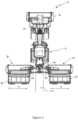
- FIG. 1a plan view of an agricultural apparatus 2 for use in the present invention is shown.
- An agricultural apparatus 2comprises an agricultural vehicle 4 such as a tractor and a number of work units 6,8,10 suitable for cutting standing crop, the work units 6,8,10 being connected to the agricultural vehicle.
- the work unitsinclude a front work unit 6 located to the front of the agricultural vehicle 4 and two lateral work units 8,10 located behind and to the sides of the front work unit 6, each of the work units 6,8,10 depositing cut crop as a swath.
- the front work unit 6is conveniently mounted on a front hitch 12 of the agricultural vehicle 4.
- the two lateral work units 8,10are conveniently mounted on a central chassis supported from a rear hitch 14 of the agricultural vehicle 4.
- the work unitscomprise mowing units.
- the lateral work units 8,10are supported from a central chassis by hydraulic units 22,24.
- Each hydraulic unit 22,24may be used to move a respective lateral work unit 8,10 from a working position to a transport position.
- a headland positionmay be defined between the working position and the transport position. In the working position the height of each of the lateral work units 8,10 above the ground surface may be further controlled by operation of the hydraulic units 22,24.
- a swath 20 produced by the front work unit 6is shown.
- conveyor units 16,18 mounted to the rear of the lateral work units 8,10will direct cut crop material to one side or the other of the respective lateral work units 8,10 to produce a broader central swath or one or more additional swathes as desired. These swathes are omitted from Figure 1 for clarity.
- the conveyor units 16, 18may be driven in any suitable manner, for example by way of a hydraulic circuit served by an accumulator on the tractor or by their own pump and reservoir mounted on the mowing unit.
- the conveyor units 16,18are mounted to be displaceable with respect to the lateral work units 8,10.
- the conveyor units 16,18are mounted to be displaced in a direction transverse to the direction of travel of the agricultural apparatus 2 (arrows A in Figure 1 ).
- the conveyor units 8,10can comprise conveyor belts or conveyor screws.
- An operatorcan control operation of the front and rear work units 6,8,10 from within the agricultural vehicle 4 by use of a suitable user terminal 30.
- the operatorcan cause each of the work units 6,8,10 to move from a working position to a headland position, can cause the rear work units 8,10 to move from the working position to a transport position, or can cause the conveyor units 16,18 to move from an active position to an inactive position.
- the user terminal 30communicates with an electronic control unit 32.
- the control unit 32provides signals to control operation of the front and rear hitches 12,14 of the agricultural vehicle 4 and provides signals to control operation of the work units 6,8,10 and the conveyor units 16,18.
- the signalsare provided by way of a suitable data communication network such as one compliant with the ISOBUS standard (a network in conformance to the ISO 11783).
- the control unit 32may conveniently comprise a single processor located on the agricultural vehicle or its functions may be split between a processor located on the agricultural vehicle and one or more additional processors located on the work units 6,8,10, the additional processor(s) being in electronic communication with the first processor.
- the control unit 32is also able to access a suitable memory 34.
- the memory 34may take any suitable form and is in electronic communication with the control unit 32.
- the memory 34is adapted to store, in any suitable manner such as a database or look up table, values for the vehicle speed with respective target values for the speed of operation of the conveyor units 16,18.
- the agricultural apparatus 2further comprises a plurality of sensors adapted to provide input signals to the control unit 32.
- An input signal representing the forward speed of the agricultural apparatus 2can be provided by a suitable sensor 36. Examples of such sensors include a sensor incorporated within an electronic control system of the agricultural vehicle 4, a speed sensor provided on the agricultural apparatus 2. Alternatively the input signal could be provided as a result of information provided by a GPS sensor.
- a network interface 42 connected to the control unit 32is provided.
- the network interface 42can comprise hardware and/or software that enables wireless connection to one or more remotely located computing devices over a network (e.g., a wireless or mixed wireless and wired network). For instance, the network interface 42 may cooperate with browser software or other software of the control unit 30 to communicate with a server device, enabling remote monitoring or control of the agricultural apparatus 2.
- Input signals representative of the speed of operation of the conveyor units 16,18may be provided by speed sensors 38 located on the agricultural apparatus 2, for example within the conveyor units 16,18. Sensors 40 mounted on the agricultural apparatus 2, for example on the conveyor units 16,18 can provide input signals representative of the transverse displacement of the conveyor units 16,18.
- the control unit 32is configured to receive the input signals representing the speed of the agricultural apparatus 2 and the speed of operation of the conveyor units 16,18 and to compare the input signals with reference values for a desired vehicle speed and speed of operation of the conveyor units 16,18 and, as required, adjust the speed of operation of at least one of the conveyor units 16,18 based on this comparison.
- control unit 32detects the increase in the vehicle speed signal (step 100, Figure 3 ) and based on a comparison of the input signals with the reference or target values stored in the memory 34, the control unit 32 causes the speed of operation of at least one conveyor unit 16,18 to be adjusted (step 102).
- the control unit 32may be configured also to receive the input signals representing the transverse displacement of the conveyor units 16,18.
- the control unit 34receives the input signals representing the speed of the agricultural apparatus 2, the speed of operation of the conveyor units 16,18 and a transverse displacement of the conveyor unit 16,18 (step 200, Figure 4 ), and based on a comparison of the input signals with the reference or target values stored in the memory 34, the control unit 32 causes the speed of operation of at least one of the conveyor units 16,18 and the transverse displacement of the conveyor unit 16,18 to be altered (step 202).
- the memory 34is adapted to store, in any suitable manner such as a database or look up table, values for the vehicle speed with respective target values for the speed of operation of the conveyor units 16,18 and the transverse displacement of the conveyor units 16,18.
- control unit 32may receive input from the user terminal 30, as entered by the operator. For instance, the operator may prompt a display of the parameters (the speed of the agricultural apparatus 2, the speed of operation of the conveyor units 16,18, the transverse displacement of the conveyor units 16,18), where the control unit 32 provides the corresponding information for rendering on a display screen in the agricultural vehicle 4 or remotely, or otherwise provided to an operator in other forms (e.g., audibly). In some embodiments, the control unit 32 may provide feedback of any automatic adjustment in the speed of the conveyor units 16,18 or the transverse position of the conveyor units 16,18 to the operator via the user terminal 30.
Landscapes
- Life Sciences & Earth Sciences (AREA)
- Environmental Sciences (AREA)
- Harvester Elements (AREA)
Description
- The present invention relates to a mower combination comprising an agricultural vehicle and a number of work units suitable for generating swathes of cut crop, that is for cutting a standing crop such as hay.
- It is known to provide a mower combination in which a first mower unit is located ahead of an agricultural vehicle such as a tractor with two further lateral mower units trailing the agricultural vehicle. The rear mower units are provided with conveyor units for depositing cut crop into a swath or swathes behind the agricultural vehicle.
- Typically the conveyor units are operated at constant speeds. This has as a disadvantage that as the speed of the agricultural vehicle is increased, the harvesting throughput increases leading to a build-up of cut crop on the conveyor units with an increasing risk that the build-up may become a blockage. When this happens mowing must stop while an operator attends to clearing of the blockage. In a time sensitive operation such a mowing, such stoppages are highly undesirable.
- It is an advantage of the present invention that this problem is addressed.
- Other advantages of the present invention will become apparent as discussed below.
- The invention is set out in the appended set of claims.
- According to a first aspect, a mower combination comprises an agricultural vehicle and a number of work units suitable for cutting a standing crop connected to the agricultural vehicle, including a front work unit and two lateral work units located behind and to the sides of the front work unit, each of the lateral work units being provided with conveyor units to deposit the cut crop as a swath, the mower combination further comprising a control unit receiving a plurality of signals, including signals representing the speed of the agricultural vehicle , the control unit being configured to receive the plurality of signals and monitor the signals representing the speed of the mower combination characterised in that a transverse position of each of the conveyor units may be altered and in that the plurality of signals further includes signals representing the speed of each of the conveyor units and a transverse position of each of the conveyor units, the control unit being configured to compare the signals representing the speed of the mower combination, a speed of operation of the conveyor units and a transverse position of each of the conveyor units against a predetermined set of values and to adjust the speed of operation and the transverse position of at least one conveyor unit based on this comparison.
- This has as an advantage that the speed of operation of the conveyor units can be altered to accommodate increased volumes of harvested crop.
- Preferably the signal representing the speed of the mower combination can be provided by the agricultural vehicle, by a speed sensor, such as a radar sensor, provided on the mower combination or by information provided by a GPS sensor. Preferably the conveyor units comprise conveyor belts or conveyor screws.
- Preferably, the agricultural apparatus further comprises a user terminal coupled to the control unit, the user terminal providing feedback to an operator of the adjustment of the speed of operation of the at least one conveyor unit.
- More preferably, the user terminal provides feedback to an operator of the adjustment of the transverse position of at least one conveyor unit.
- According to a second aspect, a method of operation of a mower combination comprising an agricultural vehicle and a number of work units suitable for cutting a standing crop connected to the agricultural vehicle, including a front work unit and two lateral work units located behind and to the sides of the front work unit, each of the lateral work units being provided with conveyor units to deposit the cut crop as a swath, the agricultural apparatus further comprising a control unit receiving a plurality of signals comprises the steps of: receiving in real time input signals corresponding to the speed of the agricultural vehicle, to the speed of operation of at least one conveyor unit forming a part of the mower combination and to a transverse position of the at least one conveyor unit; and automatically adjusting the speed of operation and lateral displacement of the at least one conveyor unit to be adjusted based on a comparison of the input signals with respective targeted values..
- According to a third aspect, a computer readable program comprises instructions that when executed on a control unit of a mower comination according to the first aspect to implement the method of the second aspect.
- The invention will now be described, by way of example only, with reference to the accompanying drawings, in which:
Figure 1 shows a plan view of an agricultural apparatus for use in the present invention;Figure 2 shows a schematic view of elements of an agricultural apparatus for use in the present invention;Figure 3 shows a flow diagram illustrating an example control method in accordance with the present invention; andFigure 4 shows a flow diagram illustrating an additional example control method in accordance with the present invention.- The invention will now be described in the following detailed description with reference to the drawings, wherein preferred embodiments are described in detail to enable practice of the invention. Although the invention is described with reference to these specific preferred embodiments, it will be understood that the invention is not limited to these preferred embodiments. But to the contrary, the invention includes numerous alternatives, modifications and equivalents as will become apparent from consideration of the following detailed description.
- Reference to terms such as longitudinal, transverse and vertical are made with respect to a longitudinal vehicle axis which is parallel to a normal forward direction of travel.
- With reference to
Figure 1 , a plan view of anagricultural apparatus 2 for use in the present invention is shown. - An
agricultural apparatus 2 comprises an agricultural vehicle 4 such as a tractor and a number ofwork units work units front work unit 6 located to the front of the agricultural vehicle 4 and twolateral work units front work unit 6, each of thework units front work unit 6 is conveniently mounted on afront hitch 12 of the agricultural vehicle 4. The twolateral work units rear hitch 14 of the agricultural vehicle 4. In a preferred embodiment the work units comprise mowing units. - The
lateral work units hydraulic units hydraulic unit lateral work unit lateral work units hydraulic units - In the illustrated embodiment a
swath 20 produced by thefront work unit 6 is shown. Inpractice conveyor units 16,18 mounted to the rear of thelateral work units lateral work units Figure 1 for clarity. - The
conveyor units 16, 18 may be driven in any suitable manner, for example by way of a hydraulic circuit served by an accumulator on the tractor or by their own pump and reservoir mounted on the mowing unit. - The
conveyor units 16,18 are mounted to be displaceable with respect to thelateral work units conveyor units 16,18 are mounted to be displaced in a direction transverse to the direction of travel of the agricultural apparatus 2 (arrows A inFigure 1 ). - A suitable arrangement to enable displacement of the conveyor units is known from the prior art.
- The
conveyor units - An operator can control operation of the front and
rear work units suitable user terminal 30. For example the operator can can cause each of thework units rear work units conveyor units 16,18 to move from an active position to an inactive position. - The
user terminal 30 communicates with anelectronic control unit 32. Thecontrol unit 32 provides signals to control operation of the front andrear hitches work units conveyor units 16,18. Conveniently the signals are provided by way of a suitable data communication network such as one compliant with the ISOBUS standard (a network in conformance to the ISO 11783). - The
control unit 32 may conveniently comprise a single processor located on the agricultural vehicle or its functions may be split between a processor located on the agricultural vehicle and one or more additional processors located on thework units - The
control unit 32 is also able to access asuitable memory 34. Thememory 34 may take any suitable form and is in electronic communication with thecontrol unit 32. Thememory 34 is adapted to store, in any suitable manner such as a database or look up table, values for the vehicle speed with respective target values for the speed of operation of theconveyor units 16,18. - The
agricultural apparatus 2 further comprises a plurality of sensors adapted to provide input signals to thecontrol unit 32. An input signal representing the forward speed of theagricultural apparatus 2 can be provided by asuitable sensor 36. Examples of such sensors include a sensor incorporated within an electronic control system of the agricultural vehicle 4, a speed sensor provided on theagricultural apparatus 2. Alternatively the input signal could be provided as a result of information provided by a GPS sensor. In the case of a GPS sensor, it will be understood that anetwork interface 42 connected to thecontrol unit 32 is provided. Thenetwork interface 42 can comprise hardware and/or software that enables wireless connection to one or more remotely located computing devices over a network (e.g., a wireless or mixed wireless and wired network). For instance, thenetwork interface 42 may cooperate with browser software or other software of thecontrol unit 30 to communicate with a server device, enabling remote monitoring or control of theagricultural apparatus 2. - Input signals representative of the speed of operation of the
conveyor units 16,18 may be provided byspeed sensors 38 located on theagricultural apparatus 2, for example within theconveyor units 16,18.Sensors 40 mounted on theagricultural apparatus 2, for example on theconveyor units 16,18 can provide input signals representative of the transverse displacement of theconveyor units 16,18. - The
control unit 32 is configured to receive the input signals representing the speed of theagricultural apparatus 2 and the speed of operation of theconveyor units 16,18 and to compare the input signals with reference values for a desired vehicle speed and speed of operation of theconveyor units 16,18 and, as required, adjust the speed of operation of at least one of theconveyor units 16,18 based on this comparison. - For example as the speed of the
agricultural apparatus 2 increases, thecontrol unit 32 detects the increase in the vehicle speed signal (step 100,Figure 3 ) and based on a comparison of the input signals with the reference or target values stored in thememory 34, thecontrol unit 32 causes the speed of operation of at least oneconveyor unit 16,18 to be adjusted (step 102). - This has as an advantage that blockage of the
conveyor units 16,18 can be avoided. - The
control unit 32 may be configured also to receive the input signals representing the transverse displacement of theconveyor units 16,18. Thecontrol unit 34 receives the input signals representing the speed of theagricultural apparatus 2, the speed of operation of theconveyor units 16,18 and a transverse displacement of the conveyor unit 16,18 (step 200,Figure 4 ), and based on a comparison of the input signals with the reference or target values stored in thememory 34, thecontrol unit 32 causes the speed of operation of at least one of theconveyor units 16,18 and the transverse displacement of theconveyor unit 16,18 to be altered (step 202). It will be understood, that in this case thememory 34 is adapted to store, in any suitable manner such as a database or look up table, values for the vehicle speed with respective target values for the speed of operation of theconveyor units 16,18 and the transverse displacement of theconveyor units 16,18. - In other embodiments, the
control unit 32 may receive input from theuser terminal 30, as entered by the operator. For instance, the operator may prompt a display of the parameters (the speed of theagricultural apparatus 2, the speed of operation of theconveyor units 16,18, the transverse displacement of the conveyor units 16,18), where thecontrol unit 32 provides the corresponding information for rendering on a display screen in the agricultural vehicle 4 or remotely, or otherwise provided to an operator in other forms (e.g., audibly). In some embodiments, thecontrol unit 32 may provide feedback of any automatic adjustment in the speed of theconveyor units 16,18 or the transverse position of theconveyor units 16,18 to the operator via theuser terminal 30. - In this way despite changing the speed of the
conveyor unit 16,18 in response to the speed of the agricultural apparatus a constant swath width is produced. This is desirable for the further processing of the cut crop by a subsequent vehicle. - From reading the present disclosure, other modifications will be apparent to persons skilled in the art. Such modifications may involve other features which are already known in the field of mowers and component parts therefore and which may be used instead of or in addition to features already described herein.
Claims (5)
- A mower combination comprising an agricultural vehicle (4) and a number of work units (6,8,10) suitable for cutting a standing crop connected to the agricultural vehicle (4), including a front work unit (6) and two lateral work units (8,10) located behind and to the sides of the front work unit (6), each of the lateral work units (8,10) being provided with conveyor units (16,18) to deposit the cut crop as a swath (20), the mower combination further comprising a control unit (32) receiving a plurality of signals, including signals representing the speed of the mower combination, the control unit (32) being configured to monitor the plurality of signals representing the speed of the mower combination,characterised in that a tranverse position of each of the conveyor units (16,18) may be altered andin that the plurality of signals further includes signals representing the speed of each of the conveyor units (16,18) and a transverse position of each of the conveyor units (16,18), the control unit (32) being configured to compare the signals representing the speed of the mower combination, a speed of operation of the conveyor units (16,18) and a transverse position of each of the conveyor units (16,18) against a predetermined set of values and to adjust the speed of operation and the transverse position of at least one conveyor unit (16,18) based on this comparison.
- A mower combination according to claim 1,characterised in that the signal representing the speed of the mower combination can be provided by the agricultural vehicle (4), by a speed sensor provided on the mower combination or by information provided by a GPS sensor.
- A mower combination according to claim 1 or claim 2,characterised in that the conveyor units comprise conveyor belts or conveyor screws.
- A method of operation of a mower combination comprising an agricultural vehicle (4) and a number of work units (6,8,10) suitable for cutting a standing crop connected to the agricultural vehicle (4), including a front work unit (6) and two lateral work units (8,10) located behind and to the sides of the front work unit (6), each of the lateral work units (8,10) being provided with conveyor units (16,18) to deposit the cut crop as a swath (20), the mower combination further comprising a control unit (32) receiving a plurality of signals, the method comprising the steps of: receiving in real time input signals corresponding to the speed of the agricultural vehicle (4),to the speed of operation of at least one conveyor unit (16,18) forming a part of the mower combination and to a transverse position of the at least one conveyor unit (16,18); and automatically adjusting the speed of operation and lateral displacement of the at least one conveyor unit (16,18) based on a comparison of the input signals with respective targeted values.
- A computer readable program comprises instructions that, when implemented on a control unit of a mower combination according to any of claim 1 to claim 3 to implement the method of claim 4.
Priority Applications (1)
| Application Number | Priority Date | Filing Date | Title |
|---|---|---|---|
| SI202130075TSI3878264T1 (en) | 2020-03-11 | 2021-01-26 | Agricultural apparatus |
Applications Claiming Priority (1)
| Application Number | Priority Date | Filing Date | Title |
|---|---|---|---|
| GBGB2003488.0AGB202003488D0 (en) | 2020-03-11 | 2020-03-11 | Agricultural apparatus |
Publications (2)
| Publication Number | Publication Date |
|---|---|
| EP3878264A1 EP3878264A1 (en) | 2021-09-15 |
| EP3878264B1true EP3878264B1 (en) | 2023-10-18 |
Family
ID=70453556
Family Applications (1)
| Application Number | Title | Priority Date | Filing Date |
|---|---|---|---|
| EP21153379.9AActiveEP3878264B1 (en) | 2020-03-11 | 2021-01-26 | Agricultural apparatus |
Country Status (6)
| Country | Link |
|---|---|
| US (1) | US11980126B2 (en) |
| EP (1) | EP3878264B1 (en) |
| DK (1) | DK3878264T3 (en) |
| GB (1) | GB202003488D0 (en) |
| PL (1) | PL3878264T3 (en) |
| SI (1) | SI3878264T1 (en) |
Family Cites Families (15)
| Publication number | Priority date | Publication date | Assignee | Title |
|---|---|---|---|---|
| CA1183355B (en) | 1982-04-29 | 1985-03-05 | Glenn R. Honey | Swather |
| DE19932285A1 (en)* | 1999-07-10 | 2001-04-26 | Deere & Co | Self-propelled mower and conveyor |
| FR2837347B1 (en)* | 2002-03-21 | 2004-07-30 | Kuhn Sa | AGRICULTURAL MOWER COMPRISING A CARRIER VEHICLE AND SEVERAL WORKING UNITS |
| DE202005016401U1 (en) | 2005-10-19 | 2007-02-22 | Alois Pöttinger Maschinenfabrik Gmbh | harvester |
| DE102007004576A1 (en)* | 2007-01-24 | 2008-07-31 | Claas Selbstfahrende Erntemaschinen Gmbh | Agricultural working machine |
| PL2430921T3 (en) | 2007-04-03 | 2017-12-29 | E. I. Du Pont De Nemours And Company | Substituted benzene fungicides |
| DE102007052798A1 (en) | 2007-11-02 | 2009-05-14 | Maschinenfabrik Bernard Krone Gmbh | Self-propelled agricultural harvester |
| US8688331B2 (en)* | 2009-12-18 | 2014-04-01 | Agco Corporation | Method to enhance performance of sensor-based implement height control |
| DE202011101277U1 (en)* | 2011-05-31 | 2011-09-26 | Fella-Werke Gmbh | mower |
| DE102013002967A1 (en)* | 2013-02-22 | 2014-09-11 | Claas Saulgau Gmbh | Control device for operating a harvesting machine and harvesting machine with such a control device |
| EP2829168B2 (en)* | 2013-07-22 | 2024-06-12 | Kverneland Group Kerteminde AS | Mower |
| US9769982B2 (en)* | 2015-09-09 | 2017-09-26 | Cnh Industrial America Llc | Method and apparatus for automatically controlling a cut height of an agricultural harvester |
| GB201612224D0 (en)* | 2016-07-14 | 2016-08-31 | Agco Int Gmbh | Agricultural electric mower |
| DE102016115589A1 (en)* | 2016-08-23 | 2018-03-01 | Claas Selbstfahrende Erntemaschinen Gmbh | Ribbon cutting |
| US10849272B2 (en)* | 2018-10-02 | 2020-12-01 | Indústrias Reunidas Colombo Ltda | Grain harvesting implement |
- 2020
- 2020-03-11GBGBGB2003488.0Apatent/GB202003488D0/ennot_activeCeased
- 2021
- 2021-01-26PLPL21153379.9Tpatent/PL3878264T3/enunknown
- 2021-01-26DKDK21153379.9Tpatent/DK3878264T3/enactive
- 2021-01-26SISI202130075Tpatent/SI3878264T1/enunknown
- 2021-01-26EPEP21153379.9Apatent/EP3878264B1/enactiveActive
- 2021-03-11USUS17/199,394patent/US11980126B2/enactiveActive
Also Published As
| Publication number | Publication date |
|---|---|
| EP3878264A1 (en) | 2021-09-15 |
| GB202003488D0 (en) | 2020-04-29 |
| PL3878264T3 (en) | 2024-03-18 |
| US11980126B2 (en) | 2024-05-14 |
| DK3878264T3 (en) | 2024-01-15 |
| US20210282321A1 (en) | 2021-09-16 |
| SI3878264T1 (en) | 2023-12-29 |
Similar Documents
| Publication | Publication Date | Title |
|---|---|---|
| EP3878267B1 (en) | Mower combination | |
| US11212962B2 (en) | Field condition determination | |
| US20200187409A1 (en) | Agricultural work machine | |
| EP3878262A1 (en) | Agricultural apparatus | |
| US9832928B2 (en) | Crop sensing | |
| US9326443B2 (en) | Arrangement and method for the automatic transfer of crops from a harvesting machine to a transport vehicle | |
| US10178828B2 (en) | Per plant crop sensing resolution | |
| US20140236381A1 (en) | Crop sensing display | |
| WO2014093814A1 (en) | Predictive load estimation through forward vision | |
| US20230225246A1 (en) | Agricultural residue depositing apparatus and method | |
| US20230345879A1 (en) | Working machine and working device | |
| EP3878264B1 (en) | Agricultural apparatus | |
| EP3837954B1 (en) | Mower combination | |
| EP3837952B1 (en) | Mower combination | |
| EP3837953B1 (en) | Agricultural apparatus | |
| US20220192087A1 (en) | Agricultural apparatus | |
| US11778949B2 (en) | Mower combination with location based conveyor control | |
| EP3837956B1 (en) | Mower combination | |
| EP3878263A1 (en) | Agricultural apparatus |
Legal Events
| Date | Code | Title | Description |
|---|---|---|---|
| PUAI | Public reference made under article 153(3) epc to a published international application that has entered the european phase | Free format text:ORIGINAL CODE: 0009012 | |
| STAA | Information on the status of an ep patent application or granted ep patent | Free format text:STATUS: THE APPLICATION HAS BEEN PUBLISHED | |
| AK | Designated contracting states | Kind code of ref document:A1 Designated state(s):AL AT BE BG CH CY CZ DE DK EE ES FI FR GB GR HR HU IE IS IT LI LT LU LV MC MK MT NL NO PL PT RO RS SE SI SK SM TR | |
| STAA | Information on the status of an ep patent application or granted ep patent | Free format text:STATUS: REQUEST FOR EXAMINATION WAS MADE | |
| 17P | Request for examination filed | Effective date:20220315 | |
| RBV | Designated contracting states (corrected) | Designated state(s):AL AT BE BG CH CY CZ DE DK EE ES FI FR GB GR HR HU IE IS IT LI LT LU LV MC MK MT NL NO PL PT RO RS SE SI SK SM TR | |
| GRAP | Despatch of communication of intention to grant a patent | Free format text:ORIGINAL CODE: EPIDOSNIGR1 | |
| STAA | Information on the status of an ep patent application or granted ep patent | Free format text:STATUS: GRANT OF PATENT IS INTENDED | |
| P01 | Opt-out of the competence of the unified patent court (upc) registered | Effective date:20230518 | |
| INTG | Intention to grant announced | Effective date:20230619 | |
| GRAS | Grant fee paid | Free format text:ORIGINAL CODE: EPIDOSNIGR3 | |
| GRAA | (expected) grant | Free format text:ORIGINAL CODE: 0009210 | |
| STAA | Information on the status of an ep patent application or granted ep patent | Free format text:STATUS: THE PATENT HAS BEEN GRANTED | |
| AK | Designated contracting states | Kind code of ref document:B1 Designated state(s):AL AT BE BG CH CY CZ DE DK EE ES FI FR GB GR HR HU IE IS IT LI LT LU LV MC MK MT NL NO PL PT RO RS SE SI SK SM TR | |
| REG | Reference to a national code | Ref country code:GB Ref legal event code:FG4D | |
| REG | Reference to a national code | Ref country code:CH Ref legal event code:EP | |
| REG | Reference to a national code | Ref country code:DE Ref legal event code:R096 Ref document number:602021005878 Country of ref document:DE | |
| REG | Reference to a national code | Ref country code:IE Ref legal event code:FG4D | |
| REG | Reference to a national code | Ref country code:DK Ref legal event code:T3 Effective date:20240111 | |
| REG | Reference to a national code | Ref country code:LT Ref legal event code:MG9D | |
| REG | Reference to a national code | Ref country code:NL Ref legal event code:MP Effective date:20231018 | |
| PG25 | Lapsed in a contracting state [announced via postgrant information from national office to epo] | Ref country code:NL Free format text:LAPSE BECAUSE OF FAILURE TO SUBMIT A TRANSLATION OF THE DESCRIPTION OR TO PAY THE FEE WITHIN THE PRESCRIBED TIME-LIMIT Effective date:20231018 | |
| PG25 | Lapsed in a contracting state [announced via postgrant information from national office to epo] | Ref country code:GR Free format text:LAPSE BECAUSE OF FAILURE TO SUBMIT A TRANSLATION OF THE DESCRIPTION OR TO PAY THE FEE WITHIN THE PRESCRIBED TIME-LIMIT Effective date:20240119 | |
| PG25 | Lapsed in a contracting state [announced via postgrant information from national office to epo] | Ref country code:IS Free format text:LAPSE BECAUSE OF FAILURE TO SUBMIT A TRANSLATION OF THE DESCRIPTION OR TO PAY THE FEE WITHIN THE PRESCRIBED TIME-LIMIT Effective date:20240218 | |
| PG25 | Lapsed in a contracting state [announced via postgrant information from national office to epo] | Ref country code:LT Free format text:LAPSE BECAUSE OF FAILURE TO SUBMIT A TRANSLATION OF THE DESCRIPTION OR TO PAY THE FEE WITHIN THE PRESCRIBED TIME-LIMIT Effective date:20231018 | |
| PG25 | Lapsed in a contracting state [announced via postgrant information from national office to epo] | Ref country code:ES Free format text:LAPSE BECAUSE OF FAILURE TO SUBMIT A TRANSLATION OF THE DESCRIPTION OR TO PAY THE FEE WITHIN THE PRESCRIBED TIME-LIMIT Effective date:20231018 | |
| PG25 | Lapsed in a contracting state [announced via postgrant information from national office to epo] | Ref country code:LT Free format text:LAPSE BECAUSE OF FAILURE TO SUBMIT A TRANSLATION OF THE DESCRIPTION OR TO PAY THE FEE WITHIN THE PRESCRIBED TIME-LIMIT Effective date:20231018 Ref country code:IS Free format text:LAPSE BECAUSE OF FAILURE TO SUBMIT A TRANSLATION OF THE DESCRIPTION OR TO PAY THE FEE WITHIN THE PRESCRIBED TIME-LIMIT Effective date:20240218 Ref country code:GR Free format text:LAPSE BECAUSE OF FAILURE TO SUBMIT A TRANSLATION OF THE DESCRIPTION OR TO PAY THE FEE WITHIN THE PRESCRIBED TIME-LIMIT Effective date:20240119 Ref country code:ES Free format text:LAPSE BECAUSE OF FAILURE TO SUBMIT A TRANSLATION OF THE DESCRIPTION OR TO PAY THE FEE WITHIN THE PRESCRIBED TIME-LIMIT Effective date:20231018 Ref country code:BG Free format text:LAPSE BECAUSE OF FAILURE TO SUBMIT A TRANSLATION OF THE DESCRIPTION OR TO PAY THE FEE WITHIN THE PRESCRIBED TIME-LIMIT Effective date:20240118 Ref country code:PT Free format text:LAPSE BECAUSE OF FAILURE TO SUBMIT A TRANSLATION OF THE DESCRIPTION OR TO PAY THE FEE WITHIN THE PRESCRIBED TIME-LIMIT Effective date:20240219 | |
| PG25 | Lapsed in a contracting state [announced via postgrant information from national office to epo] | Ref country code:SE Free format text:LAPSE BECAUSE OF FAILURE TO SUBMIT A TRANSLATION OF THE DESCRIPTION OR TO PAY THE FEE WITHIN THE PRESCRIBED TIME-LIMIT Effective date:20231018 Ref country code:RS Free format text:LAPSE BECAUSE OF FAILURE TO SUBMIT A TRANSLATION OF THE DESCRIPTION OR TO PAY THE FEE WITHIN THE PRESCRIBED TIME-LIMIT Effective date:20231018 Ref country code:NO Free format text:LAPSE BECAUSE OF FAILURE TO SUBMIT A TRANSLATION OF THE DESCRIPTION OR TO PAY THE FEE WITHIN THE PRESCRIBED TIME-LIMIT Effective date:20240118 Ref country code:LV Free format text:LAPSE BECAUSE OF FAILURE TO SUBMIT A TRANSLATION OF THE DESCRIPTION OR TO PAY THE FEE WITHIN THE PRESCRIBED TIME-LIMIT Effective date:20231018 Ref country code:HR Free format text:LAPSE BECAUSE OF FAILURE TO SUBMIT A TRANSLATION OF THE DESCRIPTION OR TO PAY THE FEE WITHIN THE PRESCRIBED TIME-LIMIT Effective date:20231018 | |
| REG | Reference to a national code | Ref country code:AT Ref legal event code:UEP Ref document number:1621566 Country of ref document:AT Kind code of ref document:T Effective date:20231018 | |
| REG | Reference to a national code | Ref country code:DE Ref legal event code:R097 Ref document number:602021005878 Country of ref document:DE | |
| PG25 | Lapsed in a contracting state [announced via postgrant information from national office to epo] | Ref country code:CZ Free format text:LAPSE BECAUSE OF FAILURE TO SUBMIT A TRANSLATION OF THE DESCRIPTION OR TO PAY THE FEE WITHIN THE PRESCRIBED TIME-LIMIT Effective date:20231018 | |
| PG25 | Lapsed in a contracting state [announced via postgrant information from national office to epo] | Ref country code:SK Free format text:LAPSE BECAUSE OF FAILURE TO SUBMIT A TRANSLATION OF THE DESCRIPTION OR TO PAY THE FEE WITHIN THE PRESCRIBED TIME-LIMIT Effective date:20231018 | |
| PG25 | Lapsed in a contracting state [announced via postgrant information from national office to epo] | Ref country code:SM Free format text:LAPSE BECAUSE OF FAILURE TO SUBMIT A TRANSLATION OF THE DESCRIPTION OR TO PAY THE FEE WITHIN THE PRESCRIBED TIME-LIMIT Effective date:20231018 Ref country code:SK Free format text:LAPSE BECAUSE OF FAILURE TO SUBMIT A TRANSLATION OF THE DESCRIPTION OR TO PAY THE FEE WITHIN THE PRESCRIBED TIME-LIMIT Effective date:20231018 Ref country code:RO Free format text:LAPSE BECAUSE OF FAILURE TO SUBMIT A TRANSLATION OF THE DESCRIPTION OR TO PAY THE FEE WITHIN THE PRESCRIBED TIME-LIMIT Effective date:20231018 Ref country code:EE Free format text:LAPSE BECAUSE OF FAILURE TO SUBMIT A TRANSLATION OF THE DESCRIPTION OR TO PAY THE FEE WITHIN THE PRESCRIBED TIME-LIMIT Effective date:20231018 Ref country code:CZ Free format text:LAPSE BECAUSE OF FAILURE TO SUBMIT A TRANSLATION OF THE DESCRIPTION OR TO PAY THE FEE WITHIN THE PRESCRIBED TIME-LIMIT Effective date:20231018 | |
| PLBE | No opposition filed within time limit | Free format text:ORIGINAL CODE: 0009261 | |
| STAA | Information on the status of an ep patent application or granted ep patent | Free format text:STATUS: NO OPPOSITION FILED WITHIN TIME LIMIT | |
| PG25 | Lapsed in a contracting state [announced via postgrant information from national office to epo] | Ref country code:MC Free format text:LAPSE BECAUSE OF FAILURE TO SUBMIT A TRANSLATION OF THE DESCRIPTION OR TO PAY THE FEE WITHIN THE PRESCRIBED TIME-LIMIT Effective date:20231018 | |
| PG25 | Lapsed in a contracting state [announced via postgrant information from national office to epo] | Ref country code:MC Free format text:LAPSE BECAUSE OF FAILURE TO SUBMIT A TRANSLATION OF THE DESCRIPTION OR TO PAY THE FEE WITHIN THE PRESCRIBED TIME-LIMIT Effective date:20231018 | |
| REG | Reference to a national code | Ref country code:CH Ref legal event code:PL | |
| PG25 | Lapsed in a contracting state [announced via postgrant information from national office to epo] | Ref country code:LU Free format text:LAPSE BECAUSE OF NON-PAYMENT OF DUE FEES Effective date:20240126 | |
| 26N | No opposition filed | Effective date:20240719 | |
| PG25 | Lapsed in a contracting state [announced via postgrant information from national office to epo] | Ref country code:LU Free format text:LAPSE BECAUSE OF NON-PAYMENT OF DUE FEES Effective date:20240126 | |
| PG25 | Lapsed in a contracting state [announced via postgrant information from national office to epo] | Ref country code:BE Free format text:LAPSE BECAUSE OF NON-PAYMENT OF DUE FEES Effective date:20240131 | |
| PG25 | Lapsed in a contracting state [announced via postgrant information from national office to epo] | Ref country code:CH Free format text:LAPSE BECAUSE OF NON-PAYMENT OF DUE FEES Effective date:20240131 | |
| PG25 | Lapsed in a contracting state [announced via postgrant information from national office to epo] | Ref country code:CH Free format text:LAPSE BECAUSE OF NON-PAYMENT OF DUE FEES Effective date:20240131 Ref country code:BE Free format text:LAPSE BECAUSE OF NON-PAYMENT OF DUE FEES Effective date:20240131 | |
| REG | Reference to a national code | Ref country code:BE Ref legal event code:MM Effective date:20240131 | |
| PGFP | Annual fee paid to national office [announced via postgrant information from national office to epo] | Ref country code:DE Payment date:20250121 Year of fee payment:5 | |
| PGFP | Annual fee paid to national office [announced via postgrant information from national office to epo] | Ref country code:DK Payment date:20250124 Year of fee payment:5 | |
| PGFP | Annual fee paid to national office [announced via postgrant information from national office to epo] | Ref country code:IE Payment date:20250130 Year of fee payment:5 | |
| PGFP | Annual fee paid to national office [announced via postgrant information from national office to epo] | Ref country code:AT Payment date:20250417 Year of fee payment:5 Ref country code:SI Payment date:20250116 Year of fee payment:5 | |
| PGFP | Annual fee paid to national office [announced via postgrant information from national office to epo] | Ref country code:PL Payment date:20250116 Year of fee payment:5 Ref country code:FR Payment date:20250128 Year of fee payment:5 | |
| PGFP | Annual fee paid to national office [announced via postgrant information from national office to epo] | Ref country code:IT Payment date:20250122 Year of fee payment:5 | |
| PG25 | Lapsed in a contracting state [announced via postgrant information from national office to epo] | Ref country code:CY Free format text:LAPSE BECAUSE OF FAILURE TO SUBMIT A TRANSLATION OF THE DESCRIPTION OR TO PAY THE FEE WITHIN THE PRESCRIBED TIME-LIMIT; INVALID AB INITIO Effective date:20210126 | |
| PG25 | Lapsed in a contracting state [announced via postgrant information from national office to epo] | Ref country code:HU Free format text:LAPSE BECAUSE OF FAILURE TO SUBMIT A TRANSLATION OF THE DESCRIPTION OR TO PAY THE FEE WITHIN THE PRESCRIBED TIME-LIMIT; INVALID AB INITIO Effective date:20210126 | |
| GBPC | Gb: european patent ceased through non-payment of renewal fee | Effective date:20250126 | |
| PG25 | Lapsed in a contracting state [announced via postgrant information from national office to epo] | Ref country code:FI Free format text:LAPSE BECAUSE OF FAILURE TO SUBMIT A TRANSLATION OF THE DESCRIPTION OR TO PAY THE FEE WITHIN THE PRESCRIBED TIME-LIMIT Effective date:20231019 |