EP3877095B1 - Modular fluid application device for varying fluid coat weight - Google Patents
Modular fluid application device for varying fluid coat weightDownload PDFInfo
- Publication number
- EP3877095B1 EP3877095B1EP19836669.2AEP19836669AEP3877095B1EP 3877095 B1EP3877095 B1EP 3877095B1EP 19836669 AEP19836669 AEP 19836669AEP 3877095 B1EP3877095 B1EP 3877095B1
- Authority
- EP
- European Patent Office
- Prior art keywords
- fluid
- module
- nozzle
- air
- application device
- Prior art date
- Legal status (The legal status is an assumption and is not a legal conclusion. Google has not performed a legal analysis and makes no representation as to the accuracy of the status listed.)
- Active
Links
Images


Classifications
- B—PERFORMING OPERATIONS; TRANSPORTING
- B05—SPRAYING OR ATOMISING IN GENERAL; APPLYING FLUENT MATERIALS TO SURFACES, IN GENERAL
- B05B—SPRAYING APPARATUS; ATOMISING APPARATUS; NOZZLES
- B05B15/00—Details of spraying plant or spraying apparatus not otherwise provided for; Accessories
- B05B15/40—Filters located upstream of the spraying outlets
- B—PERFORMING OPERATIONS; TRANSPORTING
- B05—SPRAYING OR ATOMISING IN GENERAL; APPLYING FLUENT MATERIALS TO SURFACES, IN GENERAL
- B05C—APPARATUS FOR APPLYING FLUENT MATERIALS TO SURFACES, IN GENERAL
- B05C11/00—Component parts, details or accessories not specifically provided for in groups B05C1/00 - B05C9/00
- B05C11/10—Storage, supply or control of liquid or other fluent material; Recovery of excess liquid or other fluent material
- B05C11/1002—Means for controlling supply, i.e. flow or pressure, of liquid or other fluent material to the applying apparatus, e.g. valves
- B05C11/1026—Valves
- B05C11/1028—Lift valves
- B—PERFORMING OPERATIONS; TRANSPORTING
- B05—SPRAYING OR ATOMISING IN GENERAL; APPLYING FLUENT MATERIALS TO SURFACES, IN GENERAL
- B05C—APPARATUS FOR APPLYING FLUENT MATERIALS TO SURFACES, IN GENERAL
- B05C11/00—Component parts, details or accessories not specifically provided for in groups B05C1/00 - B05C9/00
- B05C11/10—Storage, supply or control of liquid or other fluent material; Recovery of excess liquid or other fluent material
- B05C11/1036—Means for supplying a selected one of a plurality of liquids or other fluent materials, or several in selected proportions, to the applying apparatus
- B—PERFORMING OPERATIONS; TRANSPORTING
- B05—SPRAYING OR ATOMISING IN GENERAL; APPLYING FLUENT MATERIALS TO SURFACES, IN GENERAL
- B05C—APPARATUS FOR APPLYING FLUENT MATERIALS TO SURFACES, IN GENERAL
- B05C11/00—Component parts, details or accessories not specifically provided for in groups B05C1/00 - B05C9/00
- B05C11/10—Storage, supply or control of liquid or other fluent material; Recovery of excess liquid or other fluent material
- B05C11/1042—Storage, supply or control of liquid or other fluent material; Recovery of excess liquid or other fluent material provided with means for heating or cooling the liquid or other fluent material in the supplying means upstream of the applying apparatus
- B—PERFORMING OPERATIONS; TRANSPORTING
- B05—SPRAYING OR ATOMISING IN GENERAL; APPLYING FLUENT MATERIALS TO SURFACES, IN GENERAL
- B05C—APPARATUS FOR APPLYING FLUENT MATERIALS TO SURFACES, IN GENERAL
- B05C5/00—Apparatus in which liquid or other fluent material is projected, poured or allowed to flow on to the surface of the work
- B05C5/02—Apparatus in which liquid or other fluent material is projected, poured or allowed to flow on to the surface of the work the liquid or other fluent material being discharged through an outlet orifice by pressure, e.g. from an outlet device in contact or almost in contact, with the work
- B05C5/0241—Apparatus in which liquid or other fluent material is projected, poured or allowed to flow on to the surface of the work the liquid or other fluent material being discharged through an outlet orifice by pressure, e.g. from an outlet device in contact or almost in contact, with the work for applying liquid or other fluent material to elongated work, e.g. wires, cables, tubes
- B—PERFORMING OPERATIONS; TRANSPORTING
- B05—SPRAYING OR ATOMISING IN GENERAL; APPLYING FLUENT MATERIALS TO SURFACES, IN GENERAL
- B05C—APPARATUS FOR APPLYING FLUENT MATERIALS TO SURFACES, IN GENERAL
- B05C5/00—Apparatus in which liquid or other fluent material is projected, poured or allowed to flow on to the surface of the work
- B05C5/02—Apparatus in which liquid or other fluent material is projected, poured or allowed to flow on to the surface of the work the liquid or other fluent material being discharged through an outlet orifice by pressure, e.g. from an outlet device in contact or almost in contact, with the work
- B05C5/027—Coating heads with several outlets, e.g. aligned transversally to the moving direction of a web to be coated
- B05C5/0275—Coating heads with several outlets, e.g. aligned transversally to the moving direction of a web to be coated flow controlled, e.g. by a valve
- B05C5/0279—Coating heads with several outlets, e.g. aligned transversally to the moving direction of a web to be coated flow controlled, e.g. by a valve independently, e.g. individually, flow controlled
- B—PERFORMING OPERATIONS; TRANSPORTING
- B05—SPRAYING OR ATOMISING IN GENERAL; APPLYING FLUENT MATERIALS TO SURFACES, IN GENERAL
- B05C—APPARATUS FOR APPLYING FLUENT MATERIALS TO SURFACES, IN GENERAL
- B05C5/00—Apparatus in which liquid or other fluent material is projected, poured or allowed to flow on to the surface of the work
- B05C5/02—Apparatus in which liquid or other fluent material is projected, poured or allowed to flow on to the surface of the work the liquid or other fluent material being discharged through an outlet orifice by pressure, e.g. from an outlet device in contact or almost in contact, with the work
- B05C5/0254—Coating heads with slot-shaped outlet
- B05C5/0258—Coating heads with slot-shaped outlet flow controlled, e.g. by a valve
Definitions
- Known fluid application devicesare used in the manufacture of various articles including disposable hygiene products.
- the known fluid application devicesare configured to discharge hot melt adhesive onto a component of the disposable hygiene product, such as a shell layer or strands of elasticated material.
- the elasticated materialmay be used, for example, in leg elastics, waist elastics and cuff elastics of the disposable hygiene product.
- US20160166441A1relates to a method, apparatus, and nozzle for applying varying amounts or types of adhesive on an elastic strand.
- US20110014430A1relates to a metering system for hot melt adhesives with variable adhesive volumes.
- US20160256889A1relates to a variable output dispensing applicator and associated methods of dispensing.
- US 20151108254discloses a gun for applying polyurethane foam or other elastomeric coatings.
- the known fluid application devicesare constructed differently depending on a particular application, for example, contact or non-contact strand coating, spray, or slot die coating applications.
- the known fluid application devicesrequire different nozzle types or configurations for certain applications.
- some applicationsrequire air to be discharged from the nozzle to act on the discharged hot melt adhesive, thereby controlling an application pattern of the adhesive, or that air be introduced within the nozzle for discharging the hot melt adhesive from the nozzle as a spray.
- Some known fluid application devicesare also configured to vary a coat weight of the fluid to be applied on the component.
- a coat weight of the fluid to be applied on the componentFor example, in a fluid application device having a slot die assembly, separate inlet ports and associated passageways and discharge ports may be provided to allow for multiple flows of the hot melt adhesive to be individually controlled. Accordingly, a first coat weight of hot melt adhesive may be applied from one discharge port, and an add-on coat weight may be selectively applied to the first coat weight from a second discharge port.
- known fluid application devicesinclude a metering device having a plurality of gear pumps mounted directly on a manifold of an applicator head.
- the metering deviceis configured to receive the hot melt adhesive from a remote supply source and meter the hot melt adhesive to individual nozzles, individual nozzle orifices, or individual valve modules to provide different volumes of the hot melt adhesive to the nozzle.
- a fluid application devicedoes not include preheated air, and thus, may be limited in the number of application patterns that can be produced.
- an application pattern of the hot melt adhesivemay be limited by the on-off cycle time of the valve.
- the on-off cycle timeis around 6 ms.
- a manufacturertypically uses different applicator equipment for the various applications above, which may result in high equipment costs, significant amounts of time where equipment is not being utilized, and a reduction in available floor space in a manufacturing facility.
- a fluid application devicethat may be configured to selectively provide heated air, allow different fluid coat weights, and interchangeably accept nozzles of different configurations, including slot die assemblies and laminated plate nozzles, for different applications. It is also desirable to reduce on-off cycle time, thereby increasing the number of possible application patterns and/or allowing for increased line speeds.
- a modular fluid application deviceincludes a module base and first and second fluid passageways extending within the module base and intersecting to form a nozzle fluid supply passageway.
- the modular fluid application devicealso includes a fluid outlet formed on a nozzle mounting surface of the module base fluidically connected to the nozzle fluid supply passageway, a base air passageway extending in the module base and an air outlet formed on the nozzle mounting surface fluidically connected to the base air passageway.
- a first module bankis removably mounted on the module base and includes at least one first module having a first valve configured to control a flow of fluid in the first fluid passageway.
- a second module bankis removably mounted on the module base and includes at least one second module having a second valve configured to control a flow of fluid in the second fluid passageway. The first module and the second module are mounted at an angle relative to one another.
- the modular fluid application devicefurther includes a filter block removably secured and fluidically connected to the module base.
- the filter blockincludes first and second fluid supply inputs and first and second filters fluidically connected to the first and second fluid supply inputs, respectively, such that the first and second filters are configured to receive the fluid from respective first and second fluid supply inputs.
- the first modulemay be fluidically connected to the first filter to receive the fluid from the first filter
- the second modulemay be fluidically connected to the second filter to receive the fluid from the second filter.
- the modular fluid application devicemay further include an air preheater removably secured and fluidically connected to the module base.
- the air preheatermay include and air supply inlet, one or more heating elements configured to heat air received through the air supply inlet, an air passageway configured to receive the heated air and an air preheater outlet for discharging the air from the air preheater.
- the one or more heating elementsmay be spiral heaters.
- the base air passagewaymay be fluidically connected to the air preheater to receive air from air preheater.
- the modular fluid application devicemay further include a nozzle removably mounted and fluidically connected to the module base on the nozzle mounting surface.
- the nozzlemay include a front plate, a backing plate and a plurality of laminated nozzle plates secured therebetween. The nozzle may be configured to receive the air and the fluid from the module base.
- the first module and the second modulemay be operable to provide a first operating state in which the first valve is open and the second valve is closed to provide a first volume of fluid to the nozzle, a second operating state in which the fist valve is closed and the second valve is open to provide a second volume of fluid to the nozzle, a third operating state in which the first valve is open and the second valve is open to provide a sum of the first volume and the second volume of fluid to the nozzle, and a fourth operating state in which the first valve is closed and the second valve is closed to substantially prevent the fluid from flowing to the nozzle.
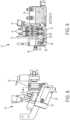
- FIG. 1is a front view of a modular fluid application device 10, according to an embodiment
- FIG. 2is a side view of the modular fluid application device 10 of FIG. 1
- FIG. 3is a top view of the modular fluid application device 10 of FIG. 1
- the modular fluid application device 10includes a module base 12 and a first module bank 14 removably mounted on the module base 12 having one or more first modules 16.
- the modular fluid application device 10also includes a second module bank 18 removably mounted on the module base 12 having one or more second modules 20.
- One or more nozzles 22may be releasably secured to a nozzle mounting surface 24 (see FIG. 4 ) of the module base 12 with a suitable fastener (not shown).
- a suitable fastenerincludes, for example, a bolt configured to extend through the nozzle 22 for receipt in a corresponding opening of the module base 12.
- the modular fluid application device 10may also include one or more mounting brackets 26 for mounting to a support (not shown).
- the modules 16, 20are fluidically connected to the module base 12.
- the modular fluid application device 10includes an air preheater 28 removably secured to the module base 12.
- the air preheater 28includes an air supply inlet 30 connected to an air supply (not shown).
- a preheater power connection 32is configured for connection to a power source (not shown).
- the modular fluid application device 10includes a filter block 34 removably secured to the module base 12.
- the filter block 34includes a first fluid supply input 36 and a second fluid supply input 38, each configured to receive a fluid, such as a hot melt adhesive, from one or more remotely positioned fluid supplies (not shown).
- the first and second fluid inputs 36, 38may each be connected to the one or more fluid supplies by a flexible supply hose (not shown).
- the same fluidis received by the first and second fluid supply inputs 36, 38.
- the fluidmay be provided to the modular fluid application 10 as two separate, discrete flows.
- the filter block 34also includes
- FIG. 4is another front view of the modular fluid application device 10, according to an embodiment, with the nozzle(s) 22 removed from the nozzle mounting surface 24.
- the nozzle mounting surface 24is formed with one or more fluid outlets 46 through which the fluid may be discharged from the module base 12 for receipt in corresponding nozzle inlets (not shown) of the one or more nozzles 22.
- the nozzle mounting surface 24may further be formed with one or more air outlets 48 though which air may be discharged from the module base 12 for receipt in corresponding nozzle air inlets (not shown) of the one or more nozzles 22.
- a nozzle 22 of the one or more nozzlesmay be fluidically connected to the module base 12 to receive the fluid, such as a hot melt adhesive, and air, such as the preheated air, from the module base 12.
- FIG. 5is a cross-sectional view taken at F-F in FIG. 4 , showing a cross section of the air preheater 28.
- the air preheater 28may include one or more heating elements 50 configured to preheat air received in the air preheater 28 via the air supply inlet 30.
- the one or more heating elements 50may be, for example spiral heating elements.
- the heating elements 50may be powered by way of the power connection 32.
- FIG. 6is a cross-sectional view of the modular fluid application device 10 taken at B-B in FIG. 4
- FIG. 7is an enlarged view showing a portion of the modular fluid application device 10, taken at detail C in FIG. 6 .
- a first module 16 of the first module bank 14 and a second module 20 of the second module bank 18may be removably mounted on the module base 12 at an angle relative to one another with respect to a machine direction 'M' for example, to extend in a non-parallel relationship.
- the module base 12may include first and second seats 52, 54 to which the first and second modules 16, 20 are mounted.
- the first and second modules 16, 20may be formed as respective valve modules each including a valve 56, 58 having a valve plug 57, 59 movable between a closed position where fluid flow is restricted or prohibited through the respective first and second fluid passageways 60, 62 and an open position where fluid flow is permitted through the respective first and second fluid passageways 60, 62.
- each of the first and second modules 16, 20either include or form in combination with a portion of the module base 12, first and second inlet chambers 64, 66 in fluid communication with the filter block 34.
- the first and second inlet chambers 64, 66are configured to receive the fluid from the first and second filters 40, 42, respectively.
- the first inlet chamber 64is fluidically connected to the first filter 40 by a first module supply passageway 68 and the second inlet chamber 66 is fluidically connected to the second filter 42 by a second module supply passageway 70.
- the first and second modules 16, 20may include respective first and second solenoids 72, 74 for actuating the valves 56, 58.
- the first and second solenoids 72, 74may be operated to allow for control air to pressurize the modules 16, 20 and move the valves 56, 58, for example, the valve plugs 57, 59 from the closed position to the open position and, in some embodiments, maintain the valves 56, 58 in the open position.
- the solenoids 72, 74may be operated to allow for control air to pressurize the modules 16, 20 to move the valve 56, 58 and plugs 57, 59 from the open position to the closed position.
- valves 56, 58may be moved against a biasing force from respective biasing members, such as coil springs, which may hold the valve 56, 58 and plugs 57, 59 in a normally closed or open position as desired.
- Powermay be supplied to the solenoids 72, 74 by a module power connection 76 ( FIG. 4 ).
- the first and second fluid passageways 60, 62may extend in one or both a respective module 16, 20 and the module base 12. In one embodiment, the first and second fluid passageways 60, 62 intersect downstream from the first and second valve modules 16, 20 to form one or more nozzle fluid supply passageways 78.
- the nozzle fluid supply passageway(s) 78fluidically connected to a corresponding fluid outlet 46 on the nozzle mounting surface 24.
- each valve module 16, 20may control fluid flow to two nozzle fluid supply passageways 78.
- FIG. 8is another side view of the modular fluid application device 10 according to an embodiment
- FIG. 9is a cross-sectional view of the modular fluid application device 10 taken at E-E in FIG. 8 , according to an embodiment.
- the air preheater 28is fluidically connected to the module base 12 such that the preheated air may be received in the module base 12 from the air preheater 28.
- the air preheater 28includes an air passageway 80 extending between the one or more heating elements 50 and an air preheater outlet 82 on a surface of the air preheater 28.
- the module base 12may include a base air inlet 84 positioned relative to the air preheater outlet 82 to receive the air from the air preheater 28.
- a base air passageway 86extends in the module base 12 from the base air inlet 84 to one or more air outlets 48 on the nozzle mounting surface 24 ( FIG. 4 ).
- the one or more air outlets 48are fluidically connected to the base air passageway 86 so that the air may be discharged from the one or more air outlets 46 for receipt in the nozzle 22.
- the first module 16 and the second module 20may be operated by moving the valves 56, 58 between open and closed positions to provide respective volumes (i.e. volume flow rates) of the fluid to the one or more nozzles 22.
- the volume of the fluid provided to the nozzle 22 by each module 16, 20is dependent upon a volume flow rate of the fluid provided to the module from first and/or second metering devices (not shown), which may be positioned remotely and upstream from the filter block 34.
- the first metering devicemay provide the fluid to the first module 16, via the filter block 34 and first filter 40, at a first volume
- the second metering devicemay provide the fluid to the second module 20, via the filter block 34 and second filter 42, at a second volume.
- the first volume and the second volumemay be controlled by the metering devices, and may be equal to, or different from one another. Accordingly, the first module 16 and the second module 20 may provide equal or different volumes of the fluid to the nozzle 22 depending on a desired application.
- different operating states in which different volumes (i.e., volume flow rates) of the fluid are discharged from the nozzle 22may be realized.
- first operating statethe first module 16 may be open and the second module 20 may be closed to provide the first volume of the fluid to the nozzle 22.
- second operating statethe first module 16 maybe closed and the second module 20 may be open to provide the second volume of fluid to the nozzle 22.
- third operating statethe first module 16 and the second module 20 may both be open to provide the sum of the first volume and the second volume of fluid to the nozzle 22.
- the first module 16 and the second module 20may both be closed to substantially prevent the fluid from being delivered to the nozzle 22.
- the modular fluid application device 10may switch between operating states in a predetermined manner to discharge the fluid at a desired coat weight and/or stitch pattern. Fluid provided to the nozzle may be discharged for application onto a substrate, such as a strand or layer of material, substantially according to the volume at which the fluid was provided to the nozzle.
- the nozzle 22may be a laminated plate (LP) nozzle comprising a plurality of nozzle plates 88 secured between a face plate 90 and a backing plate 92.
- the nozzle 22is configured to receive the fluid and the air from the module base 12 through the backing plate and direct the fluid and air through nozzle 22 for discharge and application on a strand of material.
- the airis discharged in a manner which causes the fluid to oscillate or vacillate, and in turn, to be applied on the strand in a non-linear pattern.
- the present disclosureis not limited to the nozzle 22 described above and shown in FIG. 1 .
- the nozzlemay be a spray nozzle in which the air and fluid are supplied to a common channel thereby causing the fluid to be sprayed in an atomized or droplet form.
- the nozzle 22 and/or the plurality nozzle plates 88may be formed as a unitary structure, instead of a laminated structure, for example, using known machining processes or additive manufacturing.
- the nozzlemay be a LP nozzle configured for use in contact strand coating applications which may be performed without supplying air to the nozzle.
- the modular fluid application device 10may be assembled without the air preheater 28, or operated without supplying preheated air to the nozzle 22, for applications in which preheated air is not used.
- the nozzlemay be a slot die assembly configured for substrate coating applications.
- the slot die assemblymay include an adapter, a front plate, and a shim package secured therebetween in a manner which will be appreciated by those having skill in the art.
- the shim packagemay include a plurality of shims, one or more of which may include a discharge slot for discharging the fluid.
- Such a slot die assemblydoes not require preheated air. Accordingly, the modular fluid application device 10 may be assembled without the air preheater 28, or operated without supplying preheated air to the nozzle 22, for this application as well.
- the filter block 34may be replaced with a conventional single inlet filter block (not shown) configured to receive a single supply or flow of fluid at a predetermined flow rate and provide the single supply of fluid to a module for controlling flow of the fluid to the nozzle 22.
- the filter block 34 described hereinmay be used while receiving a fluid flow into only one of the fluid inputs 36, 38, and/or maintaining one valve 56, 58 in the closed condition while operating the other valve 56, 58 to control the single flow of fluid to the nozzle 22.
- the fluidmay be received in the filter block 34 as at least two separate and discrete flows through the first and second supply inputs 36, 38.
- the fluidmay be maintained as separate and discrete flows through the filter block 34, the first and second modules 16, 20 and into the module 12.
- the separate flows of the fluidmay be combined in the nozzle fluid supply passageway 78 or controlled to flow alternately in the nozzle fluid supply passageway 78 based on operation of the valves 56, 58 in the first and second modules 16, 20.
- the single fluid flowmay be provided to the modular fluid application device 10 and be split into two or more fluid flows by way of a manifold (not shown).
- the first and second modules 16, 20may be operated to reduce an on-off cycle time compared to a conventional fluid application device in which a single module controls fluid flow to a nozzle.
- the first and second modules 16, 20may be operated simultaneously such that one of the modules 16, 20 may be moving to the open position while the other of the modules 16, 20 is moving to the closed position, thereby reducing the length of a time period in which fluid is not provided to the nozzle 22.
- a line speed of a substratemay be increased compared a line speed of the same in a conventional single module fluid application device, while maintaining or reducing a length of a stitch application pattern (e.g., an on-off-on-off... application pattern).
- the modular fluid application device 10 described hereinmay be operated to apply the fluid on a substrate, such as a strand or layer of material, at a variety of different coat weights without modifying the construction modular fluid application device 10. Rather, the coat weights may be modified by operating the first and second modules 16, 20, while maintaining the ability to operate at the reduced on-off cycle times.
- the first and second modules 16, 20may be operably connected to a controller configured to control operation of the valves 56, 58, for example, by operating the solenoids 72, 74.
- the controllermay include a processor, such as a microprocessor, and a memory configured to store program instructions relating to the operation of the modules 16, 20.
- the processormay execute the program instructions and control operation of the valves 56, 58 and the solenoids 72, 74 according to the program instructions.
- the controllermay also include an input/output unit configured to allow for information, signals, instructions, communications and the like to be received by and/or transmitted from the controller.
- the modular fluid application device 10 described in the embodiments abovemay be used to apply a fluid, such as a hot melt adhesive, onto a strand of material (including elasticated strands) or a layer of material, such as a barrier or shell layer.
- a fluidsuch as a hot melt adhesive
- a strand of materialincluding elasticated strands
- a layer of materialsuch as a barrier or shell layer.
- Such an applicationmay be useful in the manufacture of nonwoven products including disposable hygiene products.
- the present disclosureis not limited thereto. It is understood that the fluid application device described herein may be used in other applications as well, for example, packaging.
Landscapes
- Coating Apparatus (AREA)
- Nozzles (AREA)
Description
- Known fluid application devices are used in the manufacture of various articles including disposable hygiene products. In general, the known fluid application devices are configured to discharge hot melt adhesive onto a component of the disposable hygiene product, such as a shell layer or strands of elasticated material. The elasticated material may be used, for example, in leg elastics, waist elastics and cuff elastics of the disposable hygiene product.
US20160166441A1 relates to a method, apparatus, and nozzle for applying varying amounts or types of adhesive on an elastic strand.US20110014430A1 relates to a metering system for hot melt adhesives with variable adhesive volumes.US20160256889A1 relates to a variable output dispensing applicator and associated methods of dispensing. US 20151108254 discloses a gun for applying polyurethane foam or other elastomeric coatings.- The known fluid application devices are constructed differently depending on a particular application, for example, contact or non-contact strand coating, spray, or slot die coating applications. For example, the known fluid application devices require different nozzle types or configurations for certain applications. In addition, some applications require air to be discharged from the nozzle to act on the discharged hot melt adhesive, thereby controlling an application pattern of the adhesive, or that air be introduced within the nozzle for discharging the hot melt adhesive from the nozzle as a spray.
- Some known fluid application devices are also configured to vary a coat weight of the fluid to be applied on the component. For example, in a fluid application device having a slot die assembly, separate inlet ports and associated passageways and discharge ports may be provided to allow for multiple flows of the hot melt adhesive to be individually controlled. Accordingly, a first coat weight of hot melt adhesive may be applied from one discharge port, and an add-on coat weight may be selectively applied to the first coat weight from a second discharge port.
- In a known strand coating application, known fluid application devices include a metering device having a plurality of gear pumps mounted directly on a manifold of an applicator head. The metering device is configured to receive the hot melt adhesive from a remote supply source and meter the hot melt adhesive to individual nozzles, individual nozzle orifices, or individual valve modules to provide different volumes of the hot melt adhesive to the nozzle. However, such a fluid application device does not include preheated air, and thus, may be limited in the number of application patterns that can be produced.
- Further, in some known fluid application devices, an application pattern of the hot melt adhesive, for example, a stitch-type pattern (e.g., an on-off-on-off pattern), may be limited by the on-off cycle time of the valve. For example, with an elasticated strand moving at a constant line speed, the minimum distance between hot melt applications on the strand is dependent upon the length of time required for a valve of the module to move from an open position to a closed position, and then return to the open position. In known fluid application devices, the on-off cycle time is around 6 ms. Thus, to reduce a length of hot melt adhesive application and/or gaps between the adhesive when applying the adhesive in a stitch pattern, the line speed of the strand must be reduced, thereby increasing manufacturing time and reducing output.
- A manufacturer typically uses different applicator equipment for the various applications above, which may result in high equipment costs, significant amounts of time where equipment is not being utilized, and a reduction in available floor space in a manufacturing facility.
- Accordingly, it is desirable to provide a fluid application device that may be configured to selectively provide heated air, allow different fluid coat weights, and interchangeably accept nozzles of different configurations, including slot die assemblies and laminated plate nozzles, for different applications. It is also desirable to reduce on-off cycle time, thereby increasing the number of possible application patterns and/or allowing for increased line speeds.
- According to one aspect, a modular fluid application device includes a module base and first and second fluid passageways extending within the module base and intersecting to form a nozzle fluid supply passageway. The modular fluid application device also includes a fluid outlet formed on a nozzle mounting surface of the module base fluidically connected to the nozzle fluid supply passageway, a base air passageway extending in the module base and an air outlet formed on the nozzle mounting surface fluidically connected to the base air passageway. A first module bank is removably mounted on the module base and includes at least one first module having a first valve configured to control a flow of fluid in the first fluid passageway. A second module bank is removably mounted on the module base and includes at least one second module having a second valve configured to control a flow of fluid in the second fluid passageway. The first module and the second module are mounted at an angle relative to one another.
- The modular fluid application device further includes a filter block removably secured and fluidically connected to the module base. The filter block includes first and second fluid supply inputs and first and second filters fluidically connected to the first and second fluid supply inputs, respectively, such that the first and second filters are configured to receive the fluid from respective first and second fluid supply inputs. The first module may be fluidically connected to the first filter to receive the fluid from the first filter, and the second module may be fluidically connected to the second filter to receive the fluid from the second filter.
- The modular fluid application device may further include an air preheater removably secured and fluidically connected to the module base. The air preheater may include and air supply inlet, one or more heating elements configured to heat air received through the air supply inlet, an air passageway configured to receive the heated air and an air preheater outlet for discharging the air from the air preheater. The one or more heating elements may be spiral heaters. The base air passageway may be fluidically connected to the air preheater to receive air from air preheater.
- The modular fluid application device may further include a nozzle removably mounted and fluidically connected to the module base on the nozzle mounting surface. The nozzle may include a front plate, a backing plate and a plurality of laminated nozzle plates secured therebetween. The nozzle may be configured to receive the air and the fluid from the module base.
- The first module and the second module may be operable to provide a first operating state in which the first valve is open and the second valve is closed to provide a first volume of fluid to the nozzle, a second operating state in which the fist valve is closed and the second valve is open to provide a second volume of fluid to the nozzle, a third operating state in which the first valve is open and the second valve is open to provide a sum of the first volume and the second volume of fluid to the nozzle, and a fourth operating state in which the first valve is closed and the second valve is closed to substantially prevent the fluid from flowing to the nozzle.
- Other objects, features, and advantages of the disclosure will be apparent from the following description, taken in conjunction with the accompanying sheets of drawings, wherein like numerals refer to like parts, elements, components, steps, and processes.
FIG. 1 is a front view of a modular fluid application device according to an embodiment;FIG. 2 is a side view of the modular fluid application device ofFIG. 1 ;FIG. 3 is a top view of the modular fluid application device ofFIG. 1 ;FIG. 4 is a front view of the modular fluid application device ofFIG. 1 with nozzles removed, according to an embodiment;FIG. 5 is a cross-sectional view of the modular fluid application device taken at F-F ofFIG. 4 , according to an embodiment;FIG. 6 is a cross-sectional view of the modular fluid application device taken at B-B ofFIG.4 , according to an embodiment;FIG. 7 is an enlarged view of a portion the modular fluid application device taken at detail C ofFIG. 4 , according to an embodiment;FIG. 8 is another side view of the modular fluid application device ofFIG. 4 , according to an embodiment; andFIG. 9 is a cross-sectional view of the modular fluid application device taken at section E-E ofFIG. 8 , according to an embodiment.- While the present disclosure is susceptible of embodiment in various forms, there is shown in the drawings and will hereinafter be described one or more embodiments with the understanding that the present disclosure is to be considered illustrative only and is not intended to limit the disclosure to any specific embodiment described or illustrated.
FIG. 1 is a front view of a modularfluid application device 10, according to an embodiment,FIG. 2 is a side view of the modularfluid application device 10 ofFIG. 1 , andFIG. 3 is a top view of the modularfluid application device 10 ofFIG. 1 . The modularfluid application device 10 includes amodule base 12 and afirst module bank 14 removably mounted on themodule base 12 having one or morefirst modules 16. The modularfluid application device 10 also includes asecond module bank 18 removably mounted on themodule base 12 having one or moresecond modules 20. One ormore nozzles 22 may be releasably secured to a nozzle mounting surface 24 (seeFIG. 4 ) of themodule base 12 with a suitable fastener (not shown). A suitable fastener includes, for example, a bolt configured to extend through thenozzle 22 for receipt in a corresponding opening of themodule base 12. The modularfluid application device 10 may also include one ormore mounting brackets 26 for mounting to a support (not shown). In one embodiment, themodules module base 12.- In one embodiment, the modular
fluid application device 10 includes anair preheater 28 removably secured to themodule base 12. Theair preheater 28 includes anair supply inlet 30 connected to an air supply (not shown). Apreheater power connection 32 is configured for connection to a power source (not shown). - In addition, the modular
fluid application device 10 includes afilter block 34 removably secured to themodule base 12. According to the invention, thefilter block 34 includes a firstfluid supply input 36 and a secondfluid supply input 38, each configured to receive a fluid, such as a hot melt adhesive, from one or more remotely positioned fluid supplies (not shown). In one embodiment, the first and secondfluid inputs fluid supply inputs fluid application 10 as two separate, discrete flows. - The
filter block 34 also includes - a first filter 40 fluidically connected to the first
fluid supply input 36 and configured to receive the fluid from the firstfluid supply input 36. Thefilter block 34 further includes - a
second filter 42 fluidically connected to the secondfluid supply input 38 and configured to receive the fluid from the secondfluid supply input 38. FIG. 4 is another front view of the modularfluid application device 10, according to an embodiment, with the nozzle(s) 22 removed from thenozzle mounting surface 24. As can be seen inFIG. 4 , thenozzle mounting surface 24 is formed with one or morefluid outlets 46 through which the fluid may be discharged from themodule base 12 for receipt in corresponding nozzle inlets (not shown) of the one ormore nozzles 22. Thenozzle mounting surface 24 may further be formed with one ormore air outlets 48 though which air may be discharged from themodule base 12 for receipt in corresponding nozzle air inlets (not shown) of the one ormore nozzles 22. In this manner, anozzle 22 of the one or more nozzles may be fluidically connected to themodule base 12 to receive the fluid, such as a hot melt adhesive, and air, such as the preheated air, from themodule base 12.FIG. 5 is a cross-sectional view taken at F-F inFIG. 4 , showing a cross section of theair preheater 28. In one embodiment, theair preheater 28 may include one ormore heating elements 50 configured to preheat air received in theair preheater 28 via theair supply inlet 30. The one ormore heating elements 50 may be, for example spiral heating elements. Theheating elements 50 may be powered by way of thepower connection 32.FIG. 6 is a cross-sectional view of the modularfluid application device 10 taken at B-B inFIG. 4 , andFIG. 7 is an enlarged view showing a portion of the modularfluid application device 10, taken at detail C inFIG. 6 . In one embodiment, afirst module 16 of thefirst module bank 14 and asecond module 20 of thesecond module bank 18 may be removably mounted on themodule base 12 at an angle relative to one another with respect to a machine direction 'M' for example, to extend in a non-parallel relationship. Accordingly, themodule base 12 may include first andsecond seats 52, 54 to which the first andsecond modules - The first and
second modules valve valve plug second fluid passageways 60, 62 and an open position where fluid flow is permitted through the respective first andsecond fluid passageways 60, 62. In addition, each of the first andsecond modules module base 12, first andsecond inlet chambers 64, 66 in fluid communication with thefilter block 34. The first andsecond inlet chambers 64, 66 are configured to receive the fluid from the first andsecond filters 40, 42, respectively. In one embodiment, thefirst inlet chamber 64 is fluidically connected to the first filter 40 by a first module supply passageway 68 and the second inlet chamber 66 is fluidically connected to thesecond filter 42 by a secondmodule supply passageway 70. - In one embodiment, the first and
second modules second solenoids valves second solenoids modules valves valves solenoids modules valve valves valve solenoids FIG. 4 ). - The first and
second fluid passageways 60, 62 may extend in one or both arespective module module base 12. In one embodiment, the first andsecond fluid passageways 60, 62 intersect downstream from the first andsecond valve modules fluid outlet 46 on thenozzle mounting surface 24. In one embodiment, eachvalve module FIG. 8 is another side view of the modularfluid application device 10 according to an embodiment, andFIG. 9 is a cross-sectional view of the modularfluid application device 10 taken at E-E inFIG. 8 , according to an embodiment. In one embodiment, theair preheater 28 is fluidically connected to themodule base 12 such that the preheated air may be received in themodule base 12 from theair preheater 28. For example, in one embodiment, theair preheater 28 includes an air passageway 80 extending between the one ormore heating elements 50 and anair preheater outlet 82 on a surface of theair preheater 28. Themodule base 12 may include abase air inlet 84 positioned relative to theair preheater outlet 82 to receive the air from theair preheater 28. Abase air passageway 86 extends in themodule base 12 from thebase air inlet 84 to one ormore air outlets 48 on the nozzle mounting surface 24 (FIG. 4 ). The one ormore air outlets 48 are fluidically connected to thebase air passageway 86 so that the air may be discharged from the one ormore air outlets 46 for receipt in thenozzle 22.- According to the embodiments herein, the
first module 16 and thesecond module 20 may be operated by moving thevalves more nozzles 22. In one embodiment, the volume of the fluid provided to thenozzle 22 by eachmodule filter block 34. In one embodiment, the first metering device may provide the fluid to thefirst module 16, via thefilter block 34 and first filter 40, at a first volume, and the second metering device may provide the fluid to thesecond module 20, via thefilter block 34 andsecond filter 42, at a second volume. The first volume and the second volume may be controlled by the metering devices, and may be equal to, or different from one another. Accordingly, thefirst module 16 and thesecond module 20 may provide equal or different volumes of the fluid to thenozzle 22 depending on a desired application. - In the manner above, different operating states in which different volumes (i.e., volume flow rates) of the fluid are discharged from the
nozzle 22 may be realized. For example, in a first operating state, thefirst module 16 may be open and thesecond module 20 may be closed to provide the first volume of the fluid to thenozzle 22. In a second operating state, thefirst module 16 maybe closed and thesecond module 20 may be open to provide the second volume of fluid to thenozzle 22. In a third operating state, thefirst module 16 and thesecond module 20 may both be open to provide the sum of the first volume and the second volume of fluid to thenozzle 22. In a fourth operating state, thefirst module 16 and thesecond module 20 may both be closed to substantially prevent the fluid from being delivered to thenozzle 22. In one embodiment, the modularfluid application device 10 may switch between operating states in a predetermined manner to discharge the fluid at a desired coat weight and/or stitch pattern. Fluid provided to the nozzle may be discharged for application onto a substrate, such as a strand or layer of material, substantially according to the volume at which the fluid was provided to the nozzle. - Referring again to
FIGS. 1 and 2 , in one embodiment, thenozzle 22 may be a laminated plate (LP) nozzle comprising a plurality ofnozzle plates 88 secured between aface plate 90 and abacking plate 92. Thenozzle 22 is configured to receive the fluid and the air from themodule base 12 through the backing plate and direct the fluid and air throughnozzle 22 for discharge and application on a strand of material. In one embodiment, the air is discharged in a manner which causes the fluid to oscillate or vacillate, and in turn, to be applied on the strand in a non-linear pattern. - However, the present disclosure is not limited to the
nozzle 22 described above and shown inFIG. 1 . For example, in one embodiment, the nozzle may be a spray nozzle in which the air and fluid are supplied to a common channel thereby causing the fluid to be sprayed in an atomized or droplet form. In some embodiments, thenozzle 22 and/or theplurality nozzle plates 88 may be formed as a unitary structure, instead of a laminated structure, for example, using known machining processes or additive manufacturing. - In one embodiment, the nozzle may be a LP nozzle configured for use in contact strand coating applications which may be performed without supplying air to the nozzle. Thus, in one embodiment, the modular
fluid application device 10 may be assembled without theair preheater 28, or operated without supplying preheated air to thenozzle 22, for applications in which preheated air is not used. - In another embodiment, the nozzle may be a slot die assembly configured for substrate coating applications. The slot die assembly may include an adapter, a front plate, and a shim package secured therebetween in a manner which will be appreciated by those having skill in the art. The shim package may include a plurality of shims, one or more of which may include a discharge slot for discharging the fluid. Such a slot die assembly does not require preheated air. Accordingly, the modular
fluid application device 10 may be assembled without theair preheater 28, or operated without supplying preheated air to thenozzle 22, for this application as well. - In the embodiments above, different fluid coat weights may be provided in the first, second, third and fourth operation states. However, in a disclosed but not claimed embodiment where different fluid coat weights are not desired, the
filter block 34 may be replaced with a conventional single inlet filter block (not shown) configured to receive a single supply or flow of fluid at a predetermined flow rate and provide the single supply of fluid to a module for controlling flow of the fluid to thenozzle 22. Alternatively, thefilter block 34 described herein may be used while receiving a fluid flow into only one of thefluid inputs valve other valve nozzle 22. - According to an embodiment described herein, the fluid may be received in the
filter block 34 as at least two separate and discrete flows through the first andsecond supply inputs filter block 34, the first andsecond modules module 12. In one embodiment, the separate flows of the fluid may be combined in the nozzle fluid supply passageway 78 or controlled to flow alternately in the nozzle fluid supply passageway 78 based on operation of thevalves second modules fluid application device 10 and be split into two or more fluid flows by way of a manifold (not shown). - Moreover, in the embodiments above, the first and
second modules second modules modules modules nozzle 22. Accordingly, in one embodiment, a line speed of a substrate, such as an elasticated strand, may be increased compared a line speed of the same in a conventional single module fluid application device, while maintaining or reducing a length of a stitch application pattern (e.g., an on-off-on-off... application pattern). Moreover, the modularfluid application device 10 described herein may be operated to apply the fluid on a substrate, such as a strand or layer of material, at a variety of different coat weights without modifying the construction modularfluid application device 10. Rather, the coat weights may be modified by operating the first andsecond modules - In one embodiment, the first and
second modules valves solenoids modules valves solenoids - The modular
fluid application device 10 described in the embodiments above may be used to apply a fluid, such as a hot melt adhesive, onto a strand of material (including elasticated strands) or a layer of material, such as a barrier or shell layer. Such an application may be useful in the manufacture of nonwoven products including disposable hygiene products. However, the present disclosure is not limited thereto. It is understood that the fluid application device described herein may be used in other applications as well, for example, packaging. - In the embodiments above, various features from one embodiment may be implemented in, used together with, or replace other features in different embodiments as suitable.
- All patents referred to herein, are hereby incorporated herein in their entirety, by reference, whether or not specifically indicated as such within the text of this disclosure.
- In the present disclosure, the words "a" or "an" are to be taken to include both the singular and the plural. Conversely, any reference to plural items shall, where appropriate, include the singular.
- From the foregoing it will be observed that numerous modifications and variations can be effectuated without departing from the scope of the novel concepts of the present invention. It is to be understood that no limitation with respect to the specific embodiments illustrated is intended or should be inferred.
Claims (10)
- A modular fluid application device (10) comprising:a module base (12);a first fluid passageway (60) extending within the module base (12);a second fluid passageway (62) extending within the module base (12) and intersecting the first fluid passageway to form a nozzle fluid supply passageway (78) downstream from the first and second fluid passageways;a fluid outlet (46) formed on a nozzle mounting surface (24) of the module base and fluidically connected to the nozzle fluid supply passageway (78);a base air passageway (86) extending in the module base (12);an air outlet (48) formed on the nozzle mounting surface (24) and fluidically connected to the base air passageway;a first module bank (14) removably mounted on the module base (12), the first module bank comprising at least one first module (16) having a first valve configured to control a flow of fluid in the first fluid passageway; anda second module bank (18) removably mounted on the module base, the second module bank comprising at least one second module (20) having a second valve configured to control a flow of fluid in the second fluid passageway,wherein the first module (16) and the second module (20) are mounted at an angle relative to one another and;
characterized by
further comprising a filter block (34) removably secured and fluidically connected to the module base (12);wherein the filter block (34) comprises first and second fluid supply inputs (36, 38) and first and second filters (40, 42) fluidically connected to the first and second fluid supply inputs, respectively, such that the first and second filters are configured to receive the fluid from respective first and second fluid supply inputs. - The modular fluid application device (10) of claim 1, wherein the first module (16) is fluidically connected to the first filter and is configured to receive the fluid from the first filter (40), and the second module (20) is fluidically connected to the second filter (42) and is configured to receive the fluid from the second filter (42).
- The modular fluid application device (10) of claim 1, further comprising an air preheater (28) removably secured and fluidically connected to the module base (12).
- The modular fluid application device (10) of claim 3, wherein the air preheater (28) comprises and air supply inlet (30), one or more heating elements (50) disposed within the air preheater configured to heat air received through the air supply inlet, an air passageway configured to receive the heated air and an air preheater outlet (82) for discharging the air from the air preheater.
- The modular fluid application device (10) of claim 4, wherein the one or more heating element (50) is a spiral heater.
- The modular fluid application device (10) of claim 4, wherein the base air passageway (86) is fluidically connected to the air preheater (28) and is configured to receive air from air preheater.
- The modular fluid application device (10) of claim 1, further comprising a nozzle (22) removably mounted and fluidically connected to the module base (12) on the nozzle mounting surface.
- The modular fluid application device (10) of claim 7, wherein the nozzle (22) comprises a front plate, a backing plate and a plurality of laminated nozzle plates (88) secured therebetween.
- The modular fluid application device (10) of claim 8, wherein the nozzle (22) is configured to receive the air and the fluid from the module base (12).
- The modular fluid application device (10) of claim 7, wherein the first module (16) and the second module (20) are operable to provide:a first operating state in which the first valve is open and the second valve is closed to provide a first volume of fluid to the nozzle (22);a second operating state in which the fist valve is closed and the second valve is open to provide a second volume of fluid to the nozzle (22);a third operating state in which the first valve is open and the second valve is open to provide a sum of the first volume and the second volume of fluid to the nozzle (22); anda fourth operating state in which the first valve is closed and the second valve is closed to substantially prevent the fluid from flowing to the nozzle (22).
Applications Claiming Priority (2)
| Application Number | Priority Date | Filing Date | Title |
|---|---|---|---|
| US201862758078P | 2018-11-09 | 2018-11-09 | |
| PCT/US2019/060297WO2020097354A2 (en) | 2018-11-09 | 2019-11-07 | Modular fluid application device for varying fluid coat weight |
Publications (2)
| Publication Number | Publication Date |
|---|---|
| EP3877095A2 EP3877095A2 (en) | 2021-09-15 |
| EP3877095B1true EP3877095B1 (en) | 2025-02-26 |
Family
ID=69165520
Family Applications (1)
| Application Number | Title | Priority Date | Filing Date |
|---|---|---|---|
| EP19836669.2AActiveEP3877095B1 (en) | 2018-11-09 | 2019-11-07 | Modular fluid application device for varying fluid coat weight |
Country Status (3)
| Country | Link |
|---|---|
| US (1) | US11684947B2 (en) |
| EP (1) | EP3877095B1 (en) |
| WO (1) | WO2020097354A2 (en) |
Families Citing this family (3)
| Publication number | Priority date | Publication date | Assignee | Title |
|---|---|---|---|---|
| JP7593741B2 (en) | 2020-03-26 | 2024-12-03 | ノードソン コーポレーション | Nozzle, adhesive application head, adhesive application device, and diaper manufacturing method |
| US20230302484A1 (en)* | 2022-03-22 | 2023-09-28 | Illinois Tool Works Inc. | Variable flow automatic configuration fluid application device |
| DE102024100607A1 (en)* | 2024-01-10 | 2025-07-10 | Khs Gmbh | Modular application device, gluing station with a plurality of corresponding application devices and method for additive manufacturing of a distribution module for an application device |
Citations (1)
| Publication number | Priority date | Publication date | Assignee | Title |
|---|---|---|---|---|
| US9168554B2 (en)* | 2011-04-11 | 2015-10-27 | Nordson Corporation | System, nozzle, and method for coating elastic strands |
Family Cites Families (168)
| Publication number | Priority date | Publication date | Assignee | Title |
|---|---|---|---|---|
| US2396449A (en)* | 1945-03-08 | 1946-03-12 | Spraying Systems Co | Spray nozzle |
| US3053223A (en)* | 1960-12-29 | 1962-09-11 | Food Saver Inc | Spray head for egg oiling machine |
| GB938031A (en) | 1961-06-12 | 1963-09-25 | Revertex Ltd | Improvements in or relating to the spraying of surfaces and to spray guns |
| US3332581A (en)* | 1965-03-15 | 1967-07-25 | Internat Shoe Machine Corp | Apparatus for dispensing adhesive |
| US3792801A (en)* | 1971-10-29 | 1974-02-19 | Nordson Corp | Thermoplastic applicator with self-cleaning supply reservoir |
| FR2185088A5 (en)* | 1972-05-16 | 1973-12-28 | Air Ind | |
| US3942469A (en)* | 1972-12-15 | 1976-03-09 | Ppg Industries, Inc. | Vapor deposition nozzle |
| US3888649A (en)* | 1972-12-15 | 1975-06-10 | Ppg Industries Inc | Nozzle for chemical vapor deposition of coatings |
| US3951100A (en)* | 1972-12-15 | 1976-04-20 | Ppg Industries, Inc. | Chemical vapor deposition of coatings |
| US3970037A (en)* | 1972-12-15 | 1976-07-20 | Ppg Industries, Inc. | Coating composition vaporizer |
| US3850679A (en)* | 1972-12-15 | 1974-11-26 | Ppg Industries Inc | Chemical vapor deposition of coatings |
| US4298633A (en)* | 1980-06-19 | 1981-11-03 | The Monarch Machine Tool Company | Method and apparatus for tensioning metallic strips on a slitting line |
| DE3543485A1 (en)* | 1985-12-09 | 1987-06-11 | Henning J Claassen | DEVICE FOR APPLYING A FLOWABLE APPLICATION DIMENSION |
| US4687137A (en)* | 1986-03-20 | 1987-08-18 | Nordson Corporation | Continuous/intermittent adhesive dispensing apparatus |
| US4874451A (en)* | 1986-03-20 | 1989-10-17 | Nordson Corporation | Method of forming a disposable diaper with continuous/intermittent rows of adhesive |
| EP0329813A1 (en)* | 1988-02-26 | 1989-08-30 | Nordson Corporation | Valve arrangement for intermittently applying a liquid glue to a surface |
| US5100699A (en)* | 1989-08-24 | 1992-03-31 | Minnesota Mining And Manufacturing Company | Method and apparatus for precision pumping, ratioing, and dispensing of work fluid(s) |
| IT1243378B (en)* | 1990-07-27 | 1994-06-10 | Loctite Corp | PROCEDURE AND PLANT FOR THE DISPENSING PARTICULARLY OF A SEALANT / ADHESIVE PRODUCT |
| US5145689A (en)* | 1990-10-17 | 1992-09-08 | Exxon Chemical Patents Inc. | Meltblowing die |
| US5195656A (en)* | 1991-09-03 | 1993-03-23 | Motorola, Inc. | Accurately controlled fluid dispenser with upper and lower stroke adjusters |
| US5257723A (en)* | 1992-06-02 | 1993-11-02 | Nordson Corporation | Bulk melter with material recirculation |
| US6007676A (en)* | 1992-09-29 | 1999-12-28 | Boehringer Ingelheim International Gmbh | Atomizing nozzle and filter and spray generating device |
| US5401899A (en)* | 1993-04-15 | 1995-03-28 | Westvaco Corporation | Paper machine coating system |
| GB2287894B (en)* | 1994-03-31 | 1998-02-04 | Pirelli General Plc | Valve device and resin coating apparatus incorporating same |
| US5453302A (en)* | 1994-05-16 | 1995-09-26 | Allied Tube & Conduit Corporation | In-line coating of steel tubing |
| US5618566A (en)* | 1995-04-26 | 1997-04-08 | Exxon Chemical Patents, Inc. | Modular meltblowing die |
| US5728219A (en)* | 1995-09-22 | 1998-03-17 | J&M Laboratories, Inc. | Modular die for applying adhesives |
| US5699938A (en)* | 1995-10-30 | 1997-12-23 | Nordson Corporation | Molten thermoplastic material supply system with removable drive assembly |
| US5680961A (en)* | 1995-10-30 | 1997-10-28 | Nordson Corporation | Configurable system for supplying molten thermoplastic material |
| DE19605602C1 (en)* | 1996-02-15 | 1997-11-20 | Singulus Technologies Gmbh | Device for surface coating or for painting substrates |
| US5605720A (en)* | 1996-04-04 | 1997-02-25 | J & M Laboratories Inc. | Method of continuously formulating and applying a hot melt adhesive |
| US5832178A (en)* | 1996-06-25 | 1998-11-03 | Crafco, Incorporated | Hot melt mix applicator with electrically heated hose and wand with temperature-controlled electric generator |
| US5862986A (en)* | 1996-07-16 | 1999-01-26 | Illinois Tool Works, Inc. | Hot melt adhesive applicator with metering gear-driven head |
| US6368409B1 (en)* | 1997-11-25 | 2002-04-09 | Nordson Corporation | Electrostatic dispensing apparatus and method |
| US6210141B1 (en)* | 1998-02-10 | 2001-04-03 | Nordson Corporation | Modular die with quick change die tip or nozzle |
| US6220843B1 (en)* | 1998-03-13 | 2001-04-24 | Nordson Corporation | Segmented die for applying hot melt adhesives or other polymer melts |
| US6296463B1 (en)* | 1998-04-20 | 2001-10-02 | Nordson Corporation | Segmented metering die for hot melt adhesives or other polymer melts |
| US6089413A (en)* | 1998-09-15 | 2000-07-18 | Nordson Corporation | Liquid dispensing and recirculating module |
| US6322630B1 (en)* | 1998-10-30 | 2001-11-27 | Nordson Corporation | Retractable coating dispenser and method |
| US6168049B1 (en)* | 1999-11-03 | 2001-01-02 | Illinois Tool Works Inc. | Hot melt adhesive applicator with centrally located filter |
| US6514569B1 (en)* | 2000-01-14 | 2003-02-04 | Kenneth Crouch | Variable volume positive displacement dispensing system and method |
| US6488772B2 (en)* | 2000-02-16 | 2002-12-03 | Roll Carter, Inc. | Dispenser unit for a coating apparatus |
| US6401976B1 (en)* | 2000-03-23 | 2002-06-11 | Nordson Corporation | Electrically operated viscous fluid dispensing apparatus and method |
| ITPC20000016A1 (en)* | 2000-05-08 | 2001-11-08 | Giordano Villa | DISPENSING-LAYING EQUIPMENT FOR TWO-COMPONENT OR SINGLE-COMPONENT ADHESIVE. |
| US6695962B2 (en)* | 2001-05-01 | 2004-02-24 | Nutool Inc. | Anode designs for planar metal deposits with enhanced electrolyte solution blending and process of supplying electrolyte solution using such designs |
| US6641670B2 (en)* | 2000-10-12 | 2003-11-04 | Toray Industries, Inc. | Leaf coater for producing leaf type coated substrates |
| US20030131791A1 (en)* | 2000-11-21 | 2003-07-17 | Schultz Carl L. | Multiple orifice applicator system and method of using same |
| US6695923B1 (en)* | 2000-11-21 | 2004-02-24 | Sealant Equipment & Engineering, Inc. | Multiple orifice applicator system and method of using same |
| JP4681126B2 (en)* | 2000-12-13 | 2011-05-11 | 富士機械製造株式会社 | High viscosity fluid application equipment |
| DE10119633A1 (en)* | 2001-04-20 | 2002-10-24 | Nordson Corp | Fluid-distributor has basic body containing supply-duct connected to outlet duct and opening, valves and nozzles |
| JP3768116B2 (en)* | 2001-05-11 | 2006-04-19 | アスモ株式会社 | Window washer nozzle and nozzle molding tool |
| US6488846B1 (en)* | 2001-06-12 | 2002-12-03 | Rudy Marangi | Paint sprayer filter system |
| US6802903B2 (en)* | 2001-09-25 | 2004-10-12 | Becton, Dickinson And Company | Apparatus for applying adhesive to tubing |
| US6457608B1 (en)* | 2001-10-15 | 2002-10-01 | Nordson Corporation | Liquid dispensing apparatus having independently positionable liquid dispensing modules |
| US7617951B2 (en)* | 2002-01-28 | 2009-11-17 | Nordson Corporation | Compact heated air manifolds for adhesive application |
| US6836616B2 (en)* | 2002-02-14 | 2004-12-28 | Valco Cincinnati, Inc. | Molten material application machine |
| US6911232B2 (en)* | 2002-04-12 | 2005-06-28 | Nordson Corporation | Module, nozzle and method for dispensing controlled patterns of liquid material |
| ATE421388T1 (en)* | 2002-09-13 | 2009-02-15 | Windmoeller & Hoelscher | FLOOR LAYING DEVICE FOR PAPER SACKS |
| US20050241755A1 (en)* | 2002-09-13 | 2005-11-03 | Marco Daher | Device for forming a glue profile for cross-base sacks |
| US7032789B2 (en)* | 2002-10-31 | 2006-04-25 | Nordson Corporation | Solenoid using color-coded visual indicia in a liquid dispensing system |
| US7216777B2 (en)* | 2002-10-31 | 2007-05-15 | Nordson Corporation | Liquid dispensing system using color-coded visual indicia |
| US20040154531A1 (en)* | 2003-02-11 | 2004-08-12 | Bernward Bruns | Device for the application of reactive liquids |
| US6809294B2 (en)* | 2003-02-12 | 2004-10-26 | The Regents Of The University Of California | Apparatus for dispensing pavement sealants |
| JP2004249215A (en)* | 2003-02-20 | 2004-09-09 | Fuji Photo Film Co Ltd | Deaeration system of liquid and deaeration method of liquid |
| US7427424B2 (en)* | 2003-08-07 | 2008-09-23 | Hill David A | Systems and methods of bonding materials |
| US7296707B2 (en)* | 2004-06-10 | 2007-11-20 | Graco Minnesota Inc. | Method and apparatus for dispensing a hot-melt adhesive |
| US20060086820A1 (en)* | 2004-10-27 | 2006-04-27 | Byers Bruce E | Self-cleaning fluid delivery system |
| US7584908B2 (en)* | 2005-10-27 | 2009-09-08 | Sta-Rite Industries, Llc | Spray nozzle apparatus and method |
| EP1946849B1 (en)* | 2005-11-10 | 2014-03-05 | Ulvac, Inc. | Applicator and method of moving dispersion liquid |
| WO2007064625A1 (en)* | 2005-12-01 | 2007-06-07 | 3M Innovative Properties Company | Multi-component liquid spray systems |
| JP4842691B2 (en)* | 2005-12-08 | 2011-12-21 | 矢崎総業株式会社 | Electric wire coloring apparatus and electric wire coloring method |
| CN101356014B (en)* | 2006-01-06 | 2013-04-24 | 诺信公司 | Liquid distributors with individual process air controls |
| US8167170B2 (en)* | 2006-06-15 | 2012-05-01 | Handy & Harman | Adhesive dispenser system |
| US9233825B2 (en)* | 2006-10-25 | 2016-01-12 | Stephen J. Madigan | Heatable personal lubricant dispensor |
| US8474660B2 (en)* | 2006-11-15 | 2013-07-02 | Nordson Corporation | Dispensing apparatus having a pivot actuator |
| US7703706B2 (en)* | 2007-01-12 | 2010-04-27 | Rain Bird Corporation | Variable arc nozzle |
| US7874456B2 (en)* | 2007-02-12 | 2011-01-25 | Illinois Tool Works Inc. | Modular system for delivering hot melt adhesive or other thermoplastic materials, and pressure control system therefor |
| US7770760B2 (en)* | 2007-02-12 | 2010-08-10 | Illinois Tool Works Inc. | Modular system for the delivery of hot melt adhesive or other thermoplastic materials |
| US8033243B2 (en)* | 2007-06-29 | 2011-10-11 | Illinois Tool Works Inc. | Strand positioning guide having reversely oriented V-shaped slots for use in connection with strand coating applicators |
| US8413848B2 (en)* | 2008-04-25 | 2013-04-09 | Illinois Tool Works Inc. | Hot melt adhesive metering system with interchangeable output assemblies |
| US7913937B2 (en)* | 2008-05-02 | 2011-03-29 | Spraying Systems Co. | Descaling spray nozzle assembly |
| KR101667067B1 (en)* | 2008-10-22 | 2016-10-17 | 그라코 미네소타 인크. | Portable airless sprayer |
| EP3354340A1 (en)* | 2009-04-03 | 2018-08-01 | Cataler Corporation | Method and apparatus of manufacturing exhaust gas-purifying catalyst and nozzle used therefor |
| US8445061B2 (en)* | 2009-07-17 | 2013-05-21 | Illinois Tool Works Inc. | Metering system for hot melt adhesives with variable adhesive volumes |
| US9573159B2 (en)* | 2009-08-31 | 2017-02-21 | Illinois Tool Works, Inc. | Metering system for simultaneously dispensing two different adhesives from a single metering device or applicator onto a common substrate |
| EP2485851A4 (en)* | 2009-10-05 | 2014-04-30 | Nordson Corp | Two-component liquid dispenser gun and system |
| US9610604B2 (en)* | 2010-02-18 | 2017-04-04 | Adco Products, Llc | Multi-bead applicator |
| US10239087B2 (en)* | 2010-02-18 | 2019-03-26 | Adco Products, Llc | Multi-bead applicator |
| US9174234B2 (en)* | 2010-02-18 | 2015-11-03 | Adco Products, Llc | Method of applying a polyurethane adhesive to a substrate |
| US9089869B2 (en)* | 2010-02-18 | 2015-07-28 | Adco Products, Llc | Adhesive bead applicator |
| US9566594B2 (en)* | 2010-02-18 | 2017-02-14 | Adco Products, Llc | Adhesive applicator |
| US8534574B2 (en)* | 2010-04-08 | 2013-09-17 | Intel Corporation | Underfill material dispenser |
| CA2803928C (en)* | 2010-06-22 | 2018-05-01 | Line Travel Automated Coating Inc. | Plural component coating application system with a compressed gas flushing system and spray tip flip mechanism |
| TWM396154U (en)* | 2010-09-03 | 2011-01-11 | Kwan Ten Entpr Co Ltd | Water sprayer |
| CA2764099C (en)* | 2011-01-14 | 2019-06-04 | Automatic Coating Limited | Pipe conditioning tool for surface treatment of a pipe |
| US9067221B2 (en)* | 2013-03-29 | 2015-06-30 | Bowles Fluidics Corporation | Cup-shaped nozzle assembly with integral filter structure |
| DE102011076443B4 (en)* | 2011-05-25 | 2013-01-17 | Lechler Gmbh | Check valve for spray nozzle and nozzle tube |
| NL2008206C2 (en)* | 2012-01-31 | 2013-08-01 | Bluemarine Offshore Yard Service B V | Device and method for the coating of a surface area of a gap in the coating of a pipeline. |
| US9682392B2 (en)* | 2012-04-11 | 2017-06-20 | Nordson Corporation | Method for applying varying amounts or types of adhesive on an elastic strand |
| US9242267B2 (en)* | 2013-01-31 | 2016-01-26 | Owens Corning Intellectual Capital, Llc | Method and apparatus for mixing and applying material |
| CH707890B1 (en)* | 2013-04-15 | 2017-12-15 | Besi Switzerland Ag | Device for applying adhesive to a substrate. |
| US10537913B2 (en)* | 2013-04-29 | 2020-01-21 | Hewlett-Packard Development Company, L.P. | Selective slot coating |
| DE102013014669A1 (en)* | 2013-09-03 | 2015-03-05 | Eisenmann Ag | Device for providing an application material |
| US20150108254A1 (en) | 2013-10-22 | 2015-04-23 | Polyurethane Machinery Corporation | Spray gun |
| US9908137B2 (en)* | 2013-11-14 | 2018-03-06 | Illinois Tool Works Inc. | Fluid application device having a modular non-contact nozzle for applying fluid to an article |
| US9605669B2 (en)* | 2014-03-19 | 2017-03-28 | Graco Fluid Handling (A) Inc. | Multi-port metering pump assembly and related methods |
| WO2015151879A1 (en)* | 2014-04-01 | 2015-10-08 | テルモ株式会社 | Positioning method for balloon coating |
| US10265708B2 (en)* | 2014-07-15 | 2019-04-23 | Lunatec, Inc. | Pressurizable fluid container and flexible dispenser |
| US10124303B2 (en)* | 2014-09-05 | 2018-11-13 | Nordson Corporation | Apparatus and methods for dispensing small beads of viscous material |
| US10278921B2 (en)* | 2014-10-27 | 2019-05-07 | Graco Minnesota Inc. | Quick release solenoid assembly |
| US9931665B2 (en)* | 2014-10-28 | 2018-04-03 | Flextronics Ap, Llc | Motorized adhesive dispensing module |
| US10201844B2 (en)* | 2014-11-07 | 2019-02-12 | Kuroda Precision Industries Ltd. | Apparatus and method for manufacturing laminated iron core |
| EP3023344B1 (en)* | 2014-11-19 | 2017-07-05 | Sidel Participations, S.A.S. | A gluing system for applying glue on products |
| US9446422B2 (en)* | 2015-02-10 | 2016-09-20 | Nordson Corporation | Adhesive dispensing module and method of spraying a plurality of droplets of a liquid adhesive |
| US20160256889A1 (en)* | 2015-03-06 | 2016-09-08 | Nordson Corporation | Variable output dispensing applicator and associated methods of dispensing |
| US11045826B2 (en)* | 2015-04-21 | 2021-06-29 | Michael Matlack | Systems and methods for providing coating operations |
| US20160332186A1 (en)* | 2015-05-13 | 2016-11-17 | David Richards | Hot-Melt Apparatus and Method |
| US11167310B2 (en)* | 2015-05-13 | 2021-11-09 | The Boeing Company | Sealing assembly for forming sealant coating on a fastener, the sealing assembly comprising a light generator and a forming cup associated with the light generator |
| US9873132B2 (en)* | 2015-06-04 | 2018-01-23 | Lenovo Enterprise Solutions (Singapore) Pte. Ltd. | Digital processing equipment |
| US9844795B2 (en)* | 2015-07-15 | 2017-12-19 | Leonard Brett Hoard | Adhesive applicator |
| CN107921468B (en)* | 2015-09-02 | 2019-12-27 | 龙云株式会社 | Discharge device |
| US9889599B2 (en)* | 2015-09-15 | 2018-02-13 | Illinois Tool Works Inc. | Multi-temperature contact applicator |
| US10064325B2 (en)* | 2015-11-13 | 2018-09-04 | Capstan Ag Systems, Inc. | Systems and methods for handling fluid for application to agricultural fields |
| WO2017095219A1 (en)* | 2015-12-04 | 2017-06-08 | Medspray Bv | Spray device and spray nozzle body |
| US9771691B2 (en)* | 2016-01-28 | 2017-09-26 | Dispensing Technology Corporation | Integral melter and pump system for the application of bituminous adhesives and highway crack-sealing materials, and a method of making the same |
| DE202017007390U1 (en)* | 2016-04-04 | 2021-02-17 | Nordson Corporation | System for monitoring a liquid adhesive flow |
| US10695779B2 (en)* | 2016-09-08 | 2020-06-30 | Nordson Corporation | Applicator having active backpressure control devices |
| WO2018048993A1 (en)* | 2016-09-08 | 2018-03-15 | Nordson Corporation | System and method for active adhesive recirculation control |
| JP6957607B2 (en)* | 2016-09-08 | 2021-11-02 | ノードソン コーポレーションNordson Corporation | Remote weighing station |
| GB2553787A (en)* | 2016-09-13 | 2018-03-21 | Haydell Michael | A conditioning apparatus for providing a carrier gas |
| KR101880545B1 (en)* | 2016-09-19 | 2018-08-17 | 주식회사 에스엠뿌레 | sprayer |
| US11229923B2 (en)* | 2016-09-30 | 2022-01-25 | Musashi Engineering, Inc. | Working apparatus and working method |
| JP6844183B2 (en)* | 2016-10-04 | 2021-03-17 | セイコーエプソン株式会社 | Liquid injection device |
| US11235890B1 (en)* | 2016-10-25 | 2022-02-01 | Working Drones, Inc. | Unmanned aerial vehicle having an elevated surface sensor |
| WO2018093995A1 (en)* | 2016-11-21 | 2018-05-24 | Ecolab Usa Inc. | Material supply system with a valve assembly and a base assembly provided with an actuator |
| DE102016014943A1 (en)* | 2016-12-14 | 2018-06-14 | Dürr Systems Ag | Printhead with tempering device |
| US10471461B2 (en)* | 2017-03-01 | 2019-11-12 | Nordson Corporation | Liquid dispensing module |
| CN207042695U (en)* | 2017-07-10 | 2018-02-27 | 恺霖卫浴科技(厦门)有限公司 | A kind of gondola water faucet for being easily changed water flow |
| US10856464B2 (en)* | 2017-08-01 | 2020-12-08 | Capstan Ag Systems, Inc. | Systems and methods for suppressing vaporization of volatile fluids in agricultural fluid application systems |
| CN111163870B (en)* | 2017-08-11 | 2021-12-10 | 伊利诺斯工具制品有限公司 | Variable volume strand coating apparatus and method |
| JP7086547B2 (en)* | 2017-08-31 | 2022-06-20 | キヤノン株式会社 | Ultra fine bubble-containing liquid manufacturing equipment and manufacturing method |
| US11110483B2 (en)* | 2017-10-31 | 2021-09-07 | Nordson Corporation | Liquid material dispensing system having a sleeve heater |
| DE102017220028A1 (en)* | 2017-11-10 | 2019-05-16 | Robert Bosch Gmbh | Spraying device and method |
| CN111741817B (en)* | 2017-11-14 | 2023-03-14 | Ddp特种电子材料美国有限责任公司 | Filtered fluid dispensing device |
| US10639669B2 (en)* | 2018-03-16 | 2020-05-05 | Nordson Corporation | Electrically operated pressure control valve |
| EP3563894B1 (en)* | 2018-05-04 | 2021-12-22 | Boehringer Ingelheim International GmbH | Nebulizer and container |
| US10518988B1 (en)* | 2018-08-27 | 2019-12-31 | Integrated Dispense Solutions | Safety mechanism for use with a drum unloader |
| US10486958B1 (en)* | 2018-08-27 | 2019-11-26 | Integrated Dispense Solutions | Follower plate geometry |
| US20200070194A1 (en)* | 2018-08-29 | 2020-03-05 | Skypath, Llc | Modified impingement spray nozzle |
| DE102018124663A1 (en)* | 2018-10-05 | 2020-04-09 | Vermes Microdispensing GmbH | Dosing system with dosing agent cooling device |
| US10722909B1 (en)* | 2018-11-01 | 2020-07-28 | Paul Charles Waelder | System and method of delivering reactive fluids to an applicator |
| CN113507988A (en)* | 2019-01-24 | 2021-10-15 | 诺信公司 | Multi-material dispensing system with quick connect fluid dispenser releasably coupled to pump housing |
| ES2976661T3 (en)* | 2019-03-15 | 2024-08-06 | Nordson Corp | Hot melt adhesive foam dispensing system |
| KR20210137461A (en)* | 2019-03-15 | 2021-11-17 | 노드슨 코포레이션 | Hot Melt Adhesive Foam Dispensing System |
| CN117160786A (en)* | 2019-04-05 | 2023-12-05 | 诺信公司 | Applicator air manifold |
| CN113260462B (en)* | 2019-08-09 | 2023-01-10 | Abb瑞士股份有限公司 | Coating machine |
| US11255053B2 (en)* | 2019-08-19 | 2022-02-22 | Railroad Solutions, Inc. | Composition, device, and method for maintaining wood railroad ties |
| DE102019123200B4 (en)* | 2019-08-29 | 2021-12-30 | Marco Systemanalyse Und Entwicklung Gmbh | DEVICE AND METHOD FOR SUPPLYING A LIQUID MEDIUM |
| US12138651B2 (en)* | 2020-03-27 | 2024-11-12 | Wagner Spray Tech Corporaton | Fluid applicator |
| US11666932B2 (en)* | 2020-03-27 | 2023-06-06 | Wagner Spray Tech Corporation | Fluid applicator |
| US11896989B2 (en)* | 2020-08-26 | 2024-02-13 | Deere & Company | Work vehicle sprayer system and method with self-cleaning filter apparatus |
| US12083543B2 (en)* | 2020-08-26 | 2024-09-10 | Deere & Company | Work vehicle sprayer system and method with switching nozzle apparatus |
| US12403494B2 (en)* | 2020-08-26 | 2025-09-02 | Deere & Company | Work vehicle sprayer system and method with nozzle monitoring |
| US12330179B2 (en)* | 2020-08-26 | 2025-06-17 | Deere &Company | Work vehicle sprayer system and method with pinching nozzle apparatus |
| WO2022047433A1 (en)* | 2020-08-31 | 2022-03-03 | Cornerstone Construction Material, LLC | Method and apparatus for creating an overlay to reinforce and repair hard surfaces |
| KR20230085908A (en)* | 2020-09-09 | 2023-06-14 | 스프레잉 시스템즈 컴파니 | Liquid Dispensing System with Pressurized Air Actuated Liquid Control Piston |
| US12427282B2 (en)* | 2020-09-09 | 2025-09-30 | Covidien Lp | Systems and methods for active humidification in ventilatory support |
| US20220258201A1 (en)* | 2021-02-12 | 2022-08-18 | Johnson Matthey Public Limited Company | Powder spraying system, powder spraying nozzle and method |
- 2019
- 2019-11-07EPEP19836669.2Apatent/EP3877095B1/enactiveActive
- 2019-11-07USUS17/284,839patent/US11684947B2/enactiveActive
- 2019-11-07WOPCT/US2019/060297patent/WO2020097354A2/ennot_activeCeased
Patent Citations (1)
| Publication number | Priority date | Publication date | Assignee | Title |
|---|---|---|---|---|
| US9168554B2 (en)* | 2011-04-11 | 2015-10-27 | Nordson Corporation | System, nozzle, and method for coating elastic strands |
Also Published As
| Publication number | Publication date |
|---|---|
| US11684947B2 (en) | 2023-06-27 |
| EP3877095A2 (en) | 2021-09-15 |
| US20210387225A1 (en) | 2021-12-16 |
| WO2020097354A3 (en) | 2020-06-18 |
| WO2020097354A2 (en) | 2020-05-14 |
Similar Documents
| Publication | Publication Date | Title |
|---|---|---|
| EP3877095B1 (en) | Modular fluid application device for varying fluid coat weight | |
| EP3064280B1 (en) | Variable output dispensing applicator and associated method of dispensing | |
| EP3064279B1 (en) | Liquid dividing module for variable output dispensing applicator and associated methods | |
| JP5078233B2 (en) | Liquid dispenser with individualized process air control | |
| US20110014430A1 (en) | Metering system for hot melt adhesives with variable adhesive volumes | |
| EP3096886B1 (en) | Fluid application device having a modular contact nozzle with a fluidic oscillator | |
| JPH07171465A (en) | Continuous type molten adhesive agent applicator | |
| US9682392B2 (en) | Method for applying varying amounts or types of adhesive on an elastic strand | |
| JP6734200B2 (en) | Fluid application device with nozzle having single or multiple orifices that are individually metered | |
| EP3664938B1 (en) | Variable volume strand coating apparatus and method | |
| EP3210675A1 (en) | Method, apparatus, and nozzle for applying varying amounts or types of adhesive on an elastic strand | |
| EP3237118B1 (en) | Fluid application device | |
| EP3297767B1 (en) | Modular fluid application device compatible with different nozzle configurations |
Legal Events
| Date | Code | Title | Description |
|---|---|---|---|
| STAA | Information on the status of an ep patent application or granted ep patent | Free format text:STATUS: UNKNOWN | |
| STAA | Information on the status of an ep patent application or granted ep patent | Free format text:STATUS: THE INTERNATIONAL PUBLICATION HAS BEEN MADE | |
| PUAI | Public reference made under article 153(3) epc to a published international application that has entered the european phase | Free format text:ORIGINAL CODE: 0009012 | |
| STAA | Information on the status of an ep patent application or granted ep patent | Free format text:STATUS: REQUEST FOR EXAMINATION WAS MADE | |
| 17P | Request for examination filed | Effective date:20210423 | |
| AK | Designated contracting states | Kind code of ref document:A2 Designated state(s):AL AT BE BG CH CY CZ DE DK EE ES FI FR GB GR HR HU IE IS IT LI LT LU LV MC MK MT NL NO PL PT RO RS SE SI SK SM TR | |
| DAV | Request for validation of the european patent (deleted) | ||
| DAX | Request for extension of the european patent (deleted) | ||
| STAA | Information on the status of an ep patent application or granted ep patent | Free format text:STATUS: EXAMINATION IS IN PROGRESS | |
| 17Q | First examination report despatched | Effective date:20230627 | |
| GRAP | Despatch of communication of intention to grant a patent | Free format text:ORIGINAL CODE: EPIDOSNIGR1 | |
| STAA | Information on the status of an ep patent application or granted ep patent | Free format text:STATUS: GRANT OF PATENT IS INTENDED | |
| INTG | Intention to grant announced | Effective date:20241022 | |
| P01 | Opt-out of the competence of the unified patent court (upc) registered | Free format text:CASE NUMBER: APP_59692/2024 Effective date:20241104 | |
| GRAS | Grant fee paid | Free format text:ORIGINAL CODE: EPIDOSNIGR3 | |
| GRAA | (expected) grant | Free format text:ORIGINAL CODE: 0009210 | |
| STAA | Information on the status of an ep patent application or granted ep patent | Free format text:STATUS: THE PATENT HAS BEEN GRANTED | |
| AK | Designated contracting states | Kind code of ref document:B1 Designated state(s):AL AT BE BG CH CY CZ DE DK EE ES FI FR GB GR HR HU IE IS IT LI LT LU LV MC MK MT NL NO PL PT RO RS SE SI SK SM TR | |
| REG | Reference to a national code | Ref country code:GB Ref legal event code:FG4D | |
| REG | Reference to a national code | Ref country code:CH Ref legal event code:EP | |
| REG | Reference to a national code | Ref country code:DE Ref legal event code:R096 Ref document number:602019066598 Country of ref document:DE | |
| REG | Reference to a national code | Ref country code:IE Ref legal event code:FG4D | |
| REG | Reference to a national code | Ref country code:NL Ref legal event code:MP Effective date:20250226 | |
| PG25 | Lapsed in a contracting state [announced via postgrant information from national office to epo] | Ref country code:RS Free format text:LAPSE BECAUSE OF FAILURE TO SUBMIT A TRANSLATION OF THE DESCRIPTION OR TO PAY THE FEE WITHIN THE PRESCRIBED TIME-LIMIT Effective date:20250526 | |
| PG25 | Lapsed in a contracting state [announced via postgrant information from national office to epo] | Ref country code:FI Free format text:LAPSE BECAUSE OF FAILURE TO SUBMIT A TRANSLATION OF THE DESCRIPTION OR TO PAY THE FEE WITHIN THE PRESCRIBED TIME-LIMIT Effective date:20250226 | |
| PG25 | Lapsed in a contracting state [announced via postgrant information from national office to epo] | Ref country code:PL Free format text:LAPSE BECAUSE OF FAILURE TO SUBMIT A TRANSLATION OF THE DESCRIPTION OR TO PAY THE FEE WITHIN THE PRESCRIBED TIME-LIMIT Effective date:20250226 | |
| PG25 | Lapsed in a contracting state [announced via postgrant information from national office to epo] | Ref country code:ES Free format text:LAPSE BECAUSE OF FAILURE TO SUBMIT A TRANSLATION OF THE DESCRIPTION OR TO PAY THE FEE WITHIN THE PRESCRIBED TIME-LIMIT Effective date:20250226 | |
| REG | Reference to a national code | Ref country code:LT Ref legal event code:MG9D | |
| PG25 | Lapsed in a contracting state [announced via postgrant information from national office to epo] | Ref country code:NO Free format text:LAPSE BECAUSE OF FAILURE TO SUBMIT A TRANSLATION OF THE DESCRIPTION OR TO PAY THE FEE WITHIN THE PRESCRIBED TIME-LIMIT Effective date:20250526 Ref country code:IS Free format text:LAPSE BECAUSE OF FAILURE TO SUBMIT A TRANSLATION OF THE DESCRIPTION OR TO PAY THE FEE WITHIN THE PRESCRIBED TIME-LIMIT Effective date:20250626 | |
| PG25 | Lapsed in a contracting state [announced via postgrant information from national office to epo] | Ref country code:NL Free format text:LAPSE BECAUSE OF FAILURE TO SUBMIT A TRANSLATION OF THE DESCRIPTION OR TO PAY THE FEE WITHIN THE PRESCRIBED TIME-LIMIT Effective date:20250226 | |
| PG25 | Lapsed in a contracting state [announced via postgrant information from national office to epo] | Ref country code:HR Free format text:LAPSE BECAUSE OF FAILURE TO SUBMIT A TRANSLATION OF THE DESCRIPTION OR TO PAY THE FEE WITHIN THE PRESCRIBED TIME-LIMIT Effective date:20250226 | |
| PG25 | Lapsed in a contracting state [announced via postgrant information from national office to epo] | Ref country code:PT Free format text:LAPSE BECAUSE OF FAILURE TO SUBMIT A TRANSLATION OF THE DESCRIPTION OR TO PAY THE FEE WITHIN THE PRESCRIBED TIME-LIMIT Effective date:20250626 Ref country code:LV Free format text:LAPSE BECAUSE OF FAILURE TO SUBMIT A TRANSLATION OF THE DESCRIPTION OR TO PAY THE FEE WITHIN THE PRESCRIBED TIME-LIMIT Effective date:20250226 | |
| PG25 | Lapsed in a contracting state [announced via postgrant information from national office to epo] | Ref country code:GR Free format text:LAPSE BECAUSE OF FAILURE TO SUBMIT A TRANSLATION OF THE DESCRIPTION OR TO PAY THE FEE WITHIN THE PRESCRIBED TIME-LIMIT Effective date:20250527 Ref country code:BG Free format text:LAPSE BECAUSE OF FAILURE TO SUBMIT A TRANSLATION OF THE DESCRIPTION OR TO PAY THE FEE WITHIN THE PRESCRIBED TIME-LIMIT Effective date:20250226 | |
| REG | Reference to a national code | Ref country code:AT Ref legal event code:MK05 Ref document number:1770142 Country of ref document:AT Kind code of ref document:T Effective date:20250226 | |
| PG25 | Lapsed in a contracting state [announced via postgrant information from national office to epo] | Ref country code:SE Free format text:LAPSE BECAUSE OF FAILURE TO SUBMIT A TRANSLATION OF THE DESCRIPTION OR TO PAY THE FEE WITHIN THE PRESCRIBED TIME-LIMIT Effective date:20250226 | |
| PG25 | Lapsed in a contracting state [announced via postgrant information from national office to epo] | Ref country code:SM Free format text:LAPSE BECAUSE OF FAILURE TO SUBMIT A TRANSLATION OF THE DESCRIPTION OR TO PAY THE FEE WITHIN THE PRESCRIBED TIME-LIMIT Effective date:20250226 |