EP3876763B1 - A cartridge for a vaporizer device - Google Patents
A cartridge for a vaporizer deviceDownload PDFInfo
- Publication number
- EP3876763B1 EP3876763B1EP19835943.2AEP19835943AEP3876763B1EP 3876763 B1EP3876763 B1EP 3876763B1EP 19835943 AEP19835943 AEP 19835943AEP 3876763 B1EP3876763 B1EP 3876763B1
- Authority
- EP
- European Patent Office
- Prior art keywords
- cartridge
- vaporizer
- vaporizable material
- elongate member
- storage chamber
- Prior art date
- Legal status (The legal status is an assumption and is not a legal conclusion. Google has not performed a legal analysis and makes no representation as to the accuracy of the status listed.)
- Active
Links
Images


Classifications
- A—HUMAN NECESSITIES
- A24—TOBACCO; CIGARS; CIGARETTES; SIMULATED SMOKING DEVICES; SMOKERS' REQUISITES
- A24F—SMOKERS' REQUISITES; MATCH BOXES; SIMULATED SMOKING DEVICES
- A24F40/00—Electrically operated smoking devices; Component parts thereof; Manufacture thereof; Maintenance or testing thereof; Charging means specially adapted therefor
- A24F40/40—Constructional details, e.g. connection of cartridges and battery parts
- A24F40/42—Cartridges or containers for inhalable precursors
- A—HUMAN NECESSITIES
- A24—TOBACCO; CIGARS; CIGARETTES; SIMULATED SMOKING DEVICES; SMOKERS' REQUISITES
- A24F—SMOKERS' REQUISITES; MATCH BOXES; SIMULATED SMOKING DEVICES
- A24F40/00—Electrically operated smoking devices; Component parts thereof; Manufacture thereof; Maintenance or testing thereof; Charging means specially adapted therefor
- A24F40/10—Devices using liquid inhalable precursors
- A—HUMAN NECESSITIES
- A24—TOBACCO; CIGARS; CIGARETTES; SIMULATED SMOKING DEVICES; SMOKERS' REQUISITES
- A24F—SMOKERS' REQUISITES; MATCH BOXES; SIMULATED SMOKING DEVICES
- A24F40/00—Electrically operated smoking devices; Component parts thereof; Manufacture thereof; Maintenance or testing thereof; Charging means specially adapted therefor
- A24F40/30—Devices using two or more structurally separated inhalable precursors, e.g. using two liquid precursors in two cartridges
- A—HUMAN NECESSITIES
- A24—TOBACCO; CIGARS; CIGARETTES; SIMULATED SMOKING DEVICES; SMOKERS' REQUISITES
- A24F—SMOKERS' REQUISITES; MATCH BOXES; SIMULATED SMOKING DEVICES
- A24F40/00—Electrically operated smoking devices; Component parts thereof; Manufacture thereof; Maintenance or testing thereof; Charging means specially adapted therefor
- A24F40/40—Constructional details, e.g. connection of cartridges and battery parts
- A24F40/46—Shape or structure of electric heating means
- A24F40/465—Shape or structure of electric heating means specially adapted for induction heating
- A—HUMAN NECESSITIES
- A24—TOBACCO; CIGARS; CIGARETTES; SIMULATED SMOKING DEVICES; SMOKERS' REQUISITES
- A24F—SMOKERS' REQUISITES; MATCH BOXES; SIMULATED SMOKING DEVICES
- A24F40/00—Electrically operated smoking devices; Component parts thereof; Manufacture thereof; Maintenance or testing thereof; Charging means specially adapted therefor
- A24F40/40—Constructional details, e.g. connection of cartridges and battery parts
- A24F40/48—Fluid transfer means, e.g. pumps
- A24F40/485—Valves; Apertures
- A—HUMAN NECESSITIES
- A24—TOBACCO; CIGARS; CIGARETTES; SIMULATED SMOKING DEVICES; SMOKERS' REQUISITES
- A24F—SMOKERS' REQUISITES; MATCH BOXES; SIMULATED SMOKING DEVICES
- A24F40/00—Electrically operated smoking devices; Component parts thereof; Manufacture thereof; Maintenance or testing thereof; Charging means specially adapted therefor
- A24F40/50—Control or monitoring
- A—HUMAN NECESSITIES
- A61—MEDICAL OR VETERINARY SCIENCE; HYGIENE
- A61M—DEVICES FOR INTRODUCING MEDIA INTO, OR ONTO, THE BODY; DEVICES FOR TRANSDUCING BODY MEDIA OR FOR TAKING MEDIA FROM THE BODY; DEVICES FOR PRODUCING OR ENDING SLEEP OR STUPOR
- A61M11/00—Sprayers or atomisers specially adapted for therapeutic purposes
- A61M11/04—Sprayers or atomisers specially adapted for therapeutic purposes operated by the vapour pressure of the liquid to be sprayed or atomised
- A61M11/041—Sprayers or atomisers specially adapted for therapeutic purposes operated by the vapour pressure of the liquid to be sprayed or atomised using heaters
- A61M11/042—Sprayers or atomisers specially adapted for therapeutic purposes operated by the vapour pressure of the liquid to be sprayed or atomised using heaters electrical
- A—HUMAN NECESSITIES
- A61—MEDICAL OR VETERINARY SCIENCE; HYGIENE
- A61M—DEVICES FOR INTRODUCING MEDIA INTO, OR ONTO, THE BODY; DEVICES FOR TRANSDUCING BODY MEDIA OR FOR TAKING MEDIA FROM THE BODY; DEVICES FOR PRODUCING OR ENDING SLEEP OR STUPOR
- A61M15/00—Inhalators
- A61M15/0001—Details of inhalators; Constructional features thereof
- A61M15/002—Details of inhalators; Constructional features thereof with air flow regulating means
- A—HUMAN NECESSITIES
- A61—MEDICAL OR VETERINARY SCIENCE; HYGIENE
- A61M—DEVICES FOR INTRODUCING MEDIA INTO, OR ONTO, THE BODY; DEVICES FOR TRANSDUCING BODY MEDIA OR FOR TAKING MEDIA FROM THE BODY; DEVICES FOR PRODUCING OR ENDING SLEEP OR STUPOR
- A61M15/00—Inhalators
- A61M15/0065—Inhalators with dosage or measuring devices
- A—HUMAN NECESSITIES
- A61—MEDICAL OR VETERINARY SCIENCE; HYGIENE
- A61M—DEVICES FOR INTRODUCING MEDIA INTO, OR ONTO, THE BODY; DEVICES FOR TRANSDUCING BODY MEDIA OR FOR TAKING MEDIA FROM THE BODY; DEVICES FOR PRODUCING OR ENDING SLEEP OR STUPOR
- A61M15/00—Inhalators
- A61M15/06—Inhaling appliances shaped like cigars, cigarettes or pipes
- H—ELECTRICITY
- H01—ELECTRIC ELEMENTS
- H01F—MAGNETS; INDUCTANCES; TRANSFORMERS; SELECTION OF MATERIALS FOR THEIR MAGNETIC PROPERTIES
- H01F7/00—Magnets
- H01F7/02—Permanent magnets [PM]
- A—HUMAN NECESSITIES
- A61—MEDICAL OR VETERINARY SCIENCE; HYGIENE
- A61M—DEVICES FOR INTRODUCING MEDIA INTO, OR ONTO, THE BODY; DEVICES FOR TRANSDUCING BODY MEDIA OR FOR TAKING MEDIA FROM THE BODY; DEVICES FOR PRODUCING OR ENDING SLEEP OR STUPOR
- A61M16/00—Devices for influencing the respiratory system of patients by gas treatment, e.g. ventilators; Tracheal tubes
- A61M16/0003—Accessories therefor, e.g. sensors, vibrators, negative pressure
- A61M2016/0015—Accessories therefor, e.g. sensors, vibrators, negative pressure inhalation detectors
- A—HUMAN NECESSITIES
- A61—MEDICAL OR VETERINARY SCIENCE; HYGIENE
- A61M—DEVICES FOR INTRODUCING MEDIA INTO, OR ONTO, THE BODY; DEVICES FOR TRANSDUCING BODY MEDIA OR FOR TAKING MEDIA FROM THE BODY; DEVICES FOR PRODUCING OR ENDING SLEEP OR STUPOR
- A61M16/00—Devices for influencing the respiratory system of patients by gas treatment, e.g. ventilators; Tracheal tubes
- A61M16/0003—Accessories therefor, e.g. sensors, vibrators, negative pressure
- A61M2016/0027—Accessories therefor, e.g. sensors, vibrators, negative pressure pressure meter
- A—HUMAN NECESSITIES
- A61—MEDICAL OR VETERINARY SCIENCE; HYGIENE
- A61M—DEVICES FOR INTRODUCING MEDIA INTO, OR ONTO, THE BODY; DEVICES FOR TRANSDUCING BODY MEDIA OR FOR TAKING MEDIA FROM THE BODY; DEVICES FOR PRODUCING OR ENDING SLEEP OR STUPOR
- A61M16/00—Devices for influencing the respiratory system of patients by gas treatment, e.g. ventilators; Tracheal tubes
- A61M16/0003—Accessories therefor, e.g. sensors, vibrators, negative pressure
- A61M2016/003—Accessories therefor, e.g. sensors, vibrators, negative pressure with a flowmeter
- A61M2016/0033—Accessories therefor, e.g. sensors, vibrators, negative pressure with a flowmeter electrical
- A61M2016/0036—Accessories therefor, e.g. sensors, vibrators, negative pressure with a flowmeter electrical in the breathing tube and used in both inspiratory and expiratory phase
- A—HUMAN NECESSITIES
- A61—MEDICAL OR VETERINARY SCIENCE; HYGIENE
- A61M—DEVICES FOR INTRODUCING MEDIA INTO, OR ONTO, THE BODY; DEVICES FOR TRANSDUCING BODY MEDIA OR FOR TAKING MEDIA FROM THE BODY; DEVICES FOR PRODUCING OR ENDING SLEEP OR STUPOR
- A61M2205/00—General characteristics of the apparatus
- A61M2205/02—General characteristics of the apparatus characterised by a particular materials
- A61M2205/0272—Electro-active or magneto-active materials
- A—HUMAN NECESSITIES
- A61—MEDICAL OR VETERINARY SCIENCE; HYGIENE
- A61M—DEVICES FOR INTRODUCING MEDIA INTO, OR ONTO, THE BODY; DEVICES FOR TRANSDUCING BODY MEDIA OR FOR TAKING MEDIA FROM THE BODY; DEVICES FOR PRODUCING OR ENDING SLEEP OR STUPOR
- A61M2205/00—General characteristics of the apparatus
- A61M2205/13—General characteristics of the apparatus with means for the detection of operative contact with patient, e.g. lip sensor
- A—HUMAN NECESSITIES
- A61—MEDICAL OR VETERINARY SCIENCE; HYGIENE
- A61M—DEVICES FOR INTRODUCING MEDIA INTO, OR ONTO, THE BODY; DEVICES FOR TRANSDUCING BODY MEDIA OR FOR TAKING MEDIA FROM THE BODY; DEVICES FOR PRODUCING OR ENDING SLEEP OR STUPOR
- A61M2205/00—General characteristics of the apparatus
- A61M2205/33—Controlling, regulating or measuring
- A61M2205/3331—Pressure; Flow
- A—HUMAN NECESSITIES
- A61—MEDICAL OR VETERINARY SCIENCE; HYGIENE
- A61M—DEVICES FOR INTRODUCING MEDIA INTO, OR ONTO, THE BODY; DEVICES FOR TRANSDUCING BODY MEDIA OR FOR TAKING MEDIA FROM THE BODY; DEVICES FOR PRODUCING OR ENDING SLEEP OR STUPOR
- A61M2205/00—General characteristics of the apparatus
- A61M2205/36—General characteristics of the apparatus related to heating or cooling
- A61M2205/3653—General characteristics of the apparatus related to heating or cooling by Joule effect, i.e. electric resistance
- A—HUMAN NECESSITIES
- A61—MEDICAL OR VETERINARY SCIENCE; HYGIENE
- A61M—DEVICES FOR INTRODUCING MEDIA INTO, OR ONTO, THE BODY; DEVICES FOR TRANSDUCING BODY MEDIA OR FOR TAKING MEDIA FROM THE BODY; DEVICES FOR PRODUCING OR ENDING SLEEP OR STUPOR
- A61M2205/00—General characteristics of the apparatus
- A61M2205/82—Internal energy supply devices
- A61M2205/8206—Internal energy supply devices battery-operated
Definitions
- the subject matter described hereinrelates to a cartridge for a vaporizer device and a vaporizer device, including such a vaporizer cartridge.
- Vaporizer deviceswhich can also be referred to as vaporizers, electronic vaporizer devices, or e-vaporizer devices, can be used for delivery of an aerosol (for example, a vapor-phase and/or condensed-phase material suspended in a stationary or moving mass of air or some other gas carrier) containing one or more active ingredients by inhalation of the aerosol by a user of the vaporizing device.
- an aerosolfor example, a vapor-phase and/or condensed-phase material suspended in a stationary or moving mass of air or some other gas carrier
- active ingredientsby inhalation of the aerosol by a user of the vaporizing device.
- electronic nicotine delivery systemsinclude a class of vaporizer devices that are battery powered and that can be used to simulate the experience of smoking, but without burning of tobacco or other substances.
- Vaporizer devicesare gaining increasing popularity both for prescriptive medical use, in delivering medicaments, and for consumption of tobacco, nicotine, and other plant-based materials. Vaporizer devices can be portable, self
- a vaporizer deviceIn use of a vaporizer device, the user inhales an aerosol, colloquially referred to as "vapor," which can be generated by a heating element that vaporizes (e.g., causes a liquid or solid to at least partially transition to the gas phase) a vaporizable material, which can be liquid, a solution, a solid, a paste, a wax, and/or any other form compatible for use with a specific vaporizer device.
- the vaporizable material used with a vaporizer devicecan be provided within a cartridge for example, a separable part of the vaporizer device that contains vaporizable material) that includes an outlet (for example, a mouthpiece) for inhalation of the aerosol by a user.
- a usermay, in certain examples, activate the vaporizer device by taking a puff, by pressing a button, and/or by some other approach.
- a puff as used hereincan refer to inhalation by the user in a manner that causes a volume of air to be drawn into the vaporizer device such that the inhalable aerosol is generated by a combination of the vaporized vaporizable material with the volume of air.
- a vaporizer devicegenerates an inhalable aerosol from a vaporizable material involves heating the vaporizable material in a vaporization chamber (e.g., a heater chamber) to cause the vaporizable material to be converted to the gas (or vapor) phase.
- a vaporization chambercan refer to an area or volume in the vaporizer device within which a heat source (for example, a conductive, convective, and/or radiative heat source) causes heating of a vaporizable material to produce a mixture of air and vaporized material to form a vapor for inhalation of the vaporizable material by a user of the vaporizer device.
- a heat sourcefor example, a conductive, convective, and/or radiative heat source
- Vaporizer devicescan be controlled by one or more controllers, electronic circuits (for example, sensors, heating elements), and/or the like on the vaporizer device. Vaporizer devices can also wirelessly communicate with an external controller for example, a computing device such as a smartphone).
- a computing devicesuch as a smartphone
- the vaporizable materialcan be drawn out of a reservoir and into the vaporization chamber via a wicking element (e.g., a wick). Drawing of the vaporizable material into the vaporization chamber can be at least partially due to capillary action provided by the wicking element as the wicking element pulls the vaporizable material along the wicking element in the direction of the vaporization chamber. However, as vaporizable material is drawn out of the reservoir, the pressure inside the reservoir is reduced, thereby creating a vacuum and acting against the capillary action.
- a wicking elemente.g., a wick
- US 2018/177240 A1a thermal wick for electronic vaporizers is disclosed. Further, US 2018/160735 A1 discloses a wicking system consisting of two plates and a variable spacing between them to allow a control of the liquid flow and US 2017/0095004 A1 discloses an electronic cigarette with multiple electromagnetic switches. Another vaporizer device is disclosed in US 2014/069424 that comprises a conventional wick having a first end in contact with a reservoir and a second end in proximity with the heater. As such, improved vaporizer devices and/or vaporization cartridges that improve upon or overcome these issues are desired.
- aspects of the current subject matterrelate to vaporizer devices and to cartridges for use in a vaporizer device.
- one or more of the following featuresmay optionally be included in any feasible combination.
- a cartridgeincludes a first storage chamber and a second storage chamber, a vaporization chamber that includes an elongate member that is in fluid communication with the first storage chamber and the second storage chamber, a magnetic element, and a conductive element in selective communication with the magnetic element.
- the first storage chamberis configured to hold a first fraction of a vaporizable material and the second storage chamber is configured to hold a second fraction of the vaporizable material.
- the elongate memberextends from a first end to a second end with a channel extending therebetween, and the elongate member is configured to receive the vaporizable material.
- the magnetic elementis disposed within the channel of the elongate member.
- the magnetic elementis configured to selectively oscillate between a first position and a second position so as to substantially control the flow of the vaporizable material into the elongate member.
- the conductive elementis configured to generate a first motive force in response to receiving a first electric current to drive the magnetic element from the first position to the second position and is configured to generate a second motive force in response to receiving a second electric current to drive the magnetic element from the second position to the first position, in which the second direction is opposite of the first direction.
- the conductive elementis further configured to substantially vaporize the vaporizable material within the elongate member to a vaporized material in response to receiving the first electric current and in response to receiving the second electric current.
- the conductive elementcan have a variety of configurations.
- the conductive elementcan be a coil that is substantially wound about at least a portion of the elongate member.
- the conductive elementcan be configured to produce an alternating magnetic field.
- the first electric currentcan have a first polarity and the second electric current can have a second polarity that is opposite the first polarity.
- the magnetic elementwhen in the first position, can be configured to prevent the first fraction of the vaporizable material from flowing into the elongate member, and when in the second position, the magnetic element can be configured to prevent the second fraction of the vaporizable material from flowing into the elongate member.
- a portion of the first fraction of the vaporizable materialcan flow into the elongate member when the magnetic element is in the second position.
- an inlet valvecan be positioned at the first end of the elongate member, in which the inlet valve can be configured to substantially prevent backflow of the portion of the first fraction of the vaporizable material from the elongate member and into the first storage chamber.
- a portion of the second fraction of the vaporizable materialcan flow into the elongate member when the magnetic element is in the first position.
- an inlet valvecan be positioned at the second end of the elongate member, in which the inlet valve can be configured to substantially prevent backflow of the portion of the second fraction of the vaporizable material from the elongate member and into the second storage chamber.
- the magnetic elementcan have a variety of configurations.
- the magnetic elementcan be a permanent magnet.
- the vaporization chambercan have a variety of configurations.
- the vaporization chambercan define an airflow passageway that extends therethrough.
- the airflow passagewaycan be configured to allow the vaporized material to combine with an influx of air such that the vaporized material passes out of the vaporization chamber.
- a vaporizer devicein another embodiment, includes a vaporizer body and a cartridge according to claim 1.
- the vaporizer bodycan have a variety of configurations.
- the vaporizer bodycan include a power source.
- Implementations of the current subject matterinclude methods, apparatuses, articles of manufacture, and systems relating to vaporization of one or more materials for inhalation by a user.
- Example implementationsinclude vaporizer devices and systems including vaporizer devices.
- the term "vaporizer device” as used in the following description and claimsrefers to any of a self-contained apparatus, an apparatus that includes two or more separable parts (for example, a vaporizer body that includes a battery and other hardware, and a cartridge that includes a vaporizable material), and/or the like.
- a "vaporizer system,” as used herein,can include one or more components, such as a vaporizer device.
- vaporizer devicesconsistent with implementations of the current subject matter include electronic vaporizers, electronic nicotine delivery systems (ENDS), and/or the like.
- electronic vaporizerselectronic vaporizers
- EDSelectronic nicotine delivery systems
- vaporizer devicesare hand-held devices that heat (such as by convection, conduction, radiation, and/or some combination thereof) a vaporizable material to provide an inhalable dose of the material.
- the vaporizable material used with a vaporizer devicecan be provided within a cartridge (for example, a part of the vaporizer device that contains the vaporizable material in a reservoir or other container) which can be refillable when empty, or disposable such that a new cartridge containing additional vaporizable material of a same or different type can be used).
- a vaporizer devicecan be a cartridge-using vaporizer device, a cartridge-less vaporizer device, or a multi-use vaporizer device capable of use with or without a cartridge.
- a vaporizer devicecan include a heating chamber (for example, an oven or other region in which material is heated by a heating element) configured to receive a vaporizable material directly into the heating chamber, and/or a reservoir or the like for containing the vaporizable material.
- a heating chamberfor example, an oven or other region in which material is heated by a heating element
- a reservoir or the likefor containing the vaporizable material.
- a vaporizer devicecan be configured for use with a liquid vaporizable material (for example, a carrier solution in which an active and/or inactive ingredient(s) are suspended or held in solution, or a liquid form of the vaporizable material itself).
- a liquid vaporizable materialfor example, a carrier solution in which an active and/or inactive ingredient(s) are suspended or held in solution, or a liquid form of the vaporizable material itself.
- the liquid vaporizable materialcan be capable of being completely vaporized. Alternatively, at least a portion of the liquid vaporizable material can remain after all of the material suitable for inhalation has been vaporized.
- a vaporizer device 100can include a power source 112 (for example, a battery, which can be a rechargeable battery), and a controller 104 (for example, a processor, circuitry, etc. capable of executing logic) for controlling delivery of heat to an atomizer 141 to cause a vaporizable material 102 to be converted from a condensed form (such as a liquid, a solution, a suspension, a part of an at least partially unprocessed plant material, etc.) to the gas phase.
- the controller 104can be part of one or more printed circuit boards (PCBs) consistent with certain implementations of the current subject matter.
- At least some of the vaporizable material 102 in the gas phasecan condense to form particulate matter in at least a partial local equilibrium with the gas phase as part of an aerosol, which can form some or all of an inhalable dose provided by the vaporizer device 100 during a user's puff or draw on the vaporizer device 100.
- the interplay between gas and condensed phases in an aerosol generated by a vaporizer device 100can be complex and dynamic, due to factors such as ambient temperature, relative humidity, chemistry, flow conditions in airflow paths (both inside the vaporizer device and in the airways of a human or other animal), and/or mixing of the vaporizable material 102 in the gas phase or in the aerosol phase with other air streams, which can affect one or more physical parameters of an aerosol.
- the inhalable dosecan exist predominantly in the gas phase (for example, formation of condensed phase particles can be very limited).
- the atomizer 141 in the vaporizer device 100can be configured to vaporize a vaporizable material 102.
- the vaporizable material 102can be a liquid. Examples of the vaporizable material 102 include neat liquids, suspensions, solutions, mixtures, and/or the like.
- the atomizer 141can include a wicking element (i.e., a wick) configured to convey an amount of the vaporizable material 102 to a part of the atomizer 141 that includes a heating element (not shown in FIG. 1A ).
- the wicking elementcan be configured to draw the vaporizable material 102 from a reservoir 140 configured to contain the vaporizable material 102, such that the vaporizable material 102 can be vaporized by heat delivered from a heating element.
- the wicking elementcan also optionally allow air to enter the reservoir 140 and replace the volume of vaporizable material 102 removed.
- capillary actioncan pull vaporizable material 102 into the wick for vaporization by the heating element, and air can return to the reservoir 140 through the wick to at least partially equalize pressure in the reservoir 140.
- Other methods of allowing air back into the reservoir 140 to equalize pressureare also within the scope of the current subject matter.
- wickor “wicking element” include any material capable of causing fluid motion via capillary pressure.
- the heating elementcan include one or more of a conductive heater, a radiative heater, and/or a convective heater.
- a resistive heating elementwhich can include a material (such as a metal or alloy, for example a nickel-chromium alloy, or a non-metallic resistor) configured to dissipate electrical power in the form of heat when electrical current is passed through one or more resistive segments of the heating element.
- the atomizer 141can include a heating element which includes a resistive coil or other heating element wrapped around, positioned within, integrated into a bulk shape of, pressed into thermal contact with, or otherwise arranged to deliver heat to a wicking element, to cause the vaporizable material 102 drawn from the reservoir 140 by the wicking element to be vaporized for subsequent inhalation by a user in a gas and/or a condensed (for example, aerosol particles or droplets) phase.
- wicking elements, heating elements, and/or atomizer assembly configurationsare also possible.
- the heating elementcan be activated in association with a user puffing (i.e., drawing, inhaling, etc.) on a mouthpiece 130 of the vaporizer device 100 to cause air to flow from an air inlet, along an airflow path that passes the atomizer 141 (i.e., wicking element and heating element).
- aircan flow from an air inlet through one or more condensation areas or chambers, to an air outlet in the mouthpiece 130.
- Incoming air moving along the airflow pathmoves over or through the atomizer 141, where vaporizable material 102 in the gas phase is entrained into the air.
- the heating elementcan be activated via the controller 104, which can optionally be a part of a vaporizer body 110 as discussed herein, causing current to pass from the power source 112 through a circuit including the resistive heating element, which is optionally part of a vaporizer cartridge 120 as discussed herein.
- the entrained vaporizable material 102 in the gas phasecan condense as it passes through the remainder of the airflow path such that an inhalable dose of the vaporizable material 102 in an aerosol form can be delivered from the air outlet (for example, the mouthpiece 130) for inhalation by a user.
- Activation of the heating elementcan be caused by automatic detection of a puff based on one or more signals generated by one or more of a sensor 113.
- the sensor 113 and the signals generated by the sensor 113can include one or more of: a pressure sensor or sensors disposed to detect pressure along the airflow path relative to ambient pressure (or optionally to measure changes in absolute pressure), a motion sensor or sensors (for example, an accelerometer) of the vaporizer device 100, a flow sensor or sensors of the vaporizer device 100, a capacitive lip sensor of the vaporizer device 100, detection of interaction of a user with the vaporizer device 100 via one or more input devices 116 (for example, buttons or other tactile control devices of the vaporizer device 100), receipt of signals from a computing device in communication with the vaporizer device 100, and/or via other approaches for determining that a puff is occurring or imminent.
- a pressure sensor or sensorsdisposed to detect pressure along the airflow path relative to ambient pressure (or optionally to measure changes in absolute pressure)
- the vaporizer device 100can be configured to connect (such as, for example, wirelessly or via a wired connection) to a computing device (or optionally two or more devices) in communication with the vaporizer device 100.
- the controller 104can include communication hardware 105.
- the controller 104can also include a memory 108.
- the communication hardware 105can include firmware and/or can be controlled by software for executing one or more cryptographic protocols for the communication.
- a computing devicecan be a component of a vaporizer system that also includes the vaporizer device 100, and can include its own hardware for communication, which can establish a wireless communication channel with the communication hardware 105 of the vaporizer device 100.
- a computing device used as part of a vaporizer systemcan include a general-purpose computing device (such as a smartphone, a tablet, a personal computer, some other portable device such as a smartwatch, or the like) that executes software to produce a user interface for enabling a user to interact with the vaporizer device 100.
- such a device used as part of a vaporizer systemcan be a dedicated piece of hardware such as a remote control or other wireless or wired device having one or more physical or soft (i.e., configurable on a screen or other display device and selectable via user interaction with a touch-sensitive screen or some other input device like a mouse, pointer, trackball, cursor buttons, or the like) interface controls.
- the vaporizer device 100can also include one or more outputs 117 or devices for providing information to the user.
- the outputs 117can include one or more light emitting diodes (LEDs) configured to provide feedback to a user based on a status and/or mode of operation of the vaporizer device 100.
- LEDslight emitting diodes
- the computing deviceexecutes one or more computer instruction sets to provide a user interface and underlying data handling.
- detection by the computing device of user interaction with one or more user interface elementscan cause the computing device to signal the vaporizer device 100 to activate the heating element to reach an operating temperature for creation of an inhalable dose of vapor/aerosol.
- Other functions of the vaporizer device 100can be controlled by interaction of a user with a user interface on a computing device in communication with the vaporizer device 100.
- the temperature of a resistive heating element of the vaporizer device 100can depend on a number of factors, including an amount of electrical power delivered to the resistive heating element and/or a duty cycle at which the electrical power is delivered, conductive heat transfer to other parts of the electronic vaporizer device 100 and/or to the environment, latent heat losses due to vaporization of the vaporizable material 102 from the wicking element and/or the atomizer 141 as a whole, and convective heat losses due to airflow (i.e., air moving across the heating element or the atomizer 141 as a whole when a user inhales on the vaporizer device 100).
- the vaporizer device 100may, in some implementations of the current subject matter, make use of signals from the sensor 113 (for example, a pressure sensor) to determine when a user is inhaling.
- the sensor 113can be positioned in the airflow path and/or can be connected (for example, by a passageway or other path) to an airflow path containing an inlet for air to enter the vaporizer device 100 and an outlet via which the user inhales the resulting vapor and/or aerosol such that the sensor 113 experiences changes (for example, pressure changes) concurrently with air passing through the vaporizer device 100 from the air inlet to the air outlet.
- the heating elementcan be activated in association with a user's puff, for example by automatic detection of the puff, or by the sensor 113 detecting a change (.such as a pressure change) in the airflow path.
- the sensor 113can be positioned on or coupled to (i.e., electrically or electronically connected, either physically or via a wireless connection) the controller 104 (for example, a printed circuit board assembly or other type of circuit board).
- the controller 104for example, a printed circuit board assembly or other type of circuit board.
- the seal 127which can be a gasket, can be configured to at least partially surround the sensor 113 such that connections of the sensor 113 to the internal circuitry of the vaporizer device 100 are separated from a part of the sensor 113 exposed to the airflow path.
- the seal 127can also separate parts of one or more electrical connections between the vaporizer body 110 and the vaporizer cartridge 120. Such arrangements of the seal 127 in the vaporizer device 100 can be helpful in mitigating against potentially disruptive impacts on vaporizer components resulting from interactions with environmental factors such as water in the vapor or liquid phases, other fluids such as the vaporizable material 102, etc., and/or to reduce the escape of air from the designated airflow path in the vaporizer device 100.
- Unwanted air, liquid or other fluid passing and/or contacting circuitry of the vaporizer device 100can cause various unwanted effects, such as altered pressure readings, and/or can result in the buildup of unwanted material, such as moisture, excess vaporizable material 102, etc., in parts of the vaporizer device 100 where they can result in poor pressure signal, degradation of the sensor 113 or other components, and/or a shorter life of the vaporizer device 100.
- Leaks in the seal 127can also result in a user inhaling air that has passed over parts of the vaporizer device 100 containing, or constructed of, materials that may not be desirable to be inhaled.
- the vaporizer body 110includes the controller 104, the power source 112 (for example, a battery), one more of the sensor 113, charging contacts (such as those for charging the power source 112), the seal 127, and a cartridge receptacle 118 configured to receive the vaporizer cartridge 120 for coupling with the vaporizer body 110 through one or more of a variety of attachment structures.
- the vaporizer cartridge 120includes the reservoir 140 for containing the vaporizable material 102, and the mouthpiece 130 has an aerosol outlet for delivering an inhalable dose to a user.
- the vaporizer cartridge 120can include the atomizer 141 having a wicking element and a heating element.
- the wicking element and the heating elementcan be part of the vaporizer body 110.
- the vaporizer device 100can be configured to supply vaporizable material 102 from the reservoir 140 in the vaporizer cartridge 120 to the part(s) of the atomizer 141 included in the vaporizer body 110.
- the vaporizer device 100can include electrical connection features (for example, means for completing a circuit) for completing a circuit that includes the controller 104 (for example, a printed circuit board, a microcontroller, or the like), the power source 112, and the heating element (for example, a heating element within the atomizer 141).
- electrical connection featuresfor example, means for completing a circuit
- the controller 104for example, a printed circuit board, a microcontroller, or the like
- the power source 112for example, a heating element within the atomizer 141.
- These featurescan include one or more contacts (referred to herein as cartridge contacts 124a and 124b) on a bottom surface of the vaporizer cartridge 120 and at least two contacts (referred to herein as receptacle contacts 125a and 125b) disposed near a base of the cartridge receptacle 118 of the vaporizer device 100 such that the cartridge contacts 124a and 124b and the receptacle contacts 125a and 125b make electrical connections when the vaporizer cartridge 120 is inserted into and coupled with the cartridge receptacle 118.
- cartridge contacts 124a and 124bon a bottom surface of the vaporizer cartridge 120 and at least two contacts (referred to herein as receptacle contacts 125a and 125b) disposed near a base of the cartridge receptacle 118 of the vaporizer device 100 such that the cartridge contacts 124a and 124b and the receptacle contacts 125a and 125b make electrical connections when the vaporizer cartridge 120 is inserted into and coupled with the
- the circuit completed by these electrical connectionscan allow delivery of electrical current to a heating element and can further be used for additional functions, such as measuring a resistance of the heating element for use in determining and/or controlling a temperature of the heating element based on a thermal coefficient of resistivity of the heating element.
- the cartridge contacts 124a and 124b and the receptacle contacts 125a and 125bcan be configured to electrically connect in either of at least two orientations.
- one or more circuits necessary for operation of the vaporizer device 100can be completed by insertion of the vaporizer cartridge 120 into the cartridge receptacle 118 in a first rotational orientation (around an axis along which the vaporizer cartridge 120 is inserted into the cartridge receptacle 118 of the vaporizer body 110) such that the cartridge contact 124a is electrically connected to the receptacle contact 125a and the cartridge contact 124b is electrically connected to the receptacle contact 125b.
- the one or more circuits necessary for operation of the vaporizer device 100can be completed by insertion of the vaporizer cartridge 120 in the cartridge receptacle 118 in a second rotational orientation such cartridge contact 124a is electrically connected to the receptacle contact 125b and cartridge contact 124b is electrically connected to the receptacle contact 125a.
- the vaporizer cartridge 120 or at least the insertable end 122 of the vaporizer cartridge 120can be symmetrical upon a rotation of 180° around an axis along which the vaporizer cartridge 120 is inserted into the cartridge receptacle 118.
- the circuitry of the vaporizer device 100can support identical operation regardless of which symmetrical orientation of the vaporizer cartridge 120 occurs.
- the vaporizer body 110includes one or more detents (for example, dimples, protrusions, etc.) protruding inwardly from an inner surface of the cartridge receptacle 118, additional material (such as metal, plastic, etc.) formed to include a portion protruding into the cartridge receptacle 118, and/or the like.
- detentsfor example, dimples, protrusions, etc.
- additional materialsuch as metal, plastic, etc.
- One or more exterior surfaces of the vaporizer cartridge 120can include corresponding recesses (not shown in FIG. 1A ) that can fit and/or otherwise snap over such detents or protruding portions when the vaporizer cartridge 120 is inserted into the cartridge receptacle 118 on the vaporizer body 110.
- the detents or protrusions of the vaporizer body 110can fit within and/or otherwise be held within the recesses of the vaporizer cartridge 120, to hold the vaporizer cartridge 120 in place when assembled.
- Such an assemblycan provide enough support to hold the vaporizer cartridge 120 in place to ensure good contact between the cartridge contacts 124a and 124b and the receptacle contacts 125a and 125b, while allowing release of the vaporizer cartridge 120 from the vaporizer body 110 when a user pulls with reasonable force on the vaporizer cartridge 120 to disengage the vaporizer cartridge 120 from the cartridge receptacle 118.
- the vaporizer cartridge 120or at least an insertable end 122 of the vaporizer cartridge 120 configured for insertion in the cartridge receptacle 118, can have a non-circular cross section transverse to the axis along which the vaporizer cartridge 120 is inserted into the cartridge receptacle 118.
- the non-circular cross sectioncan be approximately rectangular, approximately elliptical (i.e., have an approximately oval shape), non-rectangular but with two sets of parallel or approximately parallel opposing sides (i.e., having a parallelogram-like shape), or other shapes having rotational symmetry of at least order two.
- approximate shapeindicates that a basic likeness to the described shape is apparent, but that sides of the shape in question need not be completely linear and vertices need not be completely sharp. Rounding of both or either of the edges or the vertices of the cross-sectional shape is contemplated in the description of any non-circular cross section referred to herein.
- the cartridge contacts 124a and 124b and the receptacle contacts 125a and 125bcan take various forms.
- one or both sets of contactscan include conductive pins, tabs, posts, receiving holes for pins or posts, or the like.
- Some types of contactscan include springs or other features to facilitate better physical and electrical contact between the contacts on the vaporizer cartridge 120 and the vaporizer body 110.
- the electrical contactscan optionally be gold-plated, and/or include other materials.
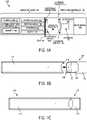
- FIGS. 1B-1Dillustrate an embodiment of the vaporizer body 110 having a cartridge receptacle 118 into which the vaporizer cartridge 120 can be releasably inserted.
- FIGS. 1B and 1Cshow top views of the vaporizer device 100 illustrating the vaporizer cartridge 120 being positioned for insertion and inserted, respectively, into the vaporizer body 110.
- FIG. 1Dillustrates the reservoir 140 of the vaporizer cartridge 120 being formed in whole or in part from translucent material such that a level of the vaporizable material 102 is visible from a window 132 (e.g., translucent material) along the vaporizer cartridge 120.
- a window 132e.g., translucent material
- the vaporizer cartridge 120can be configured such that the window 132 remains visible when insertably received by the vaporizer cartridge receptacle 118 of the vaporizer body 110.
- the window 132can be disposed between a bottom edge of the mouthpiece 130 and a top edge of the vaporizer body 110 when the vaporizer cartridge 120 is coupled with the cartridge receptacle 118.
- FIG. IEillustrates an example airflow path 134 created during a puff by a user on the vaporizer device 100.
- the airflow path 134can direct air to a vaporization chamber 150 (see FIG. IF) contained in a wick housing where the air is combined with inhalable aerosol for delivery to a user via a mouthpiece 130, which can also be part of the vaporizer cartridge 120.
- a vaporization chamber 150see FIG. IF
- a vaporization chamber 150contained in a wick housing
- the airis combined with inhalable aerosol for delivery to a user via a mouthpiece 130, which can also be part of the vaporizer cartridge 120.
- aircan pass between an outer surface of the vaporizer cartridge 120 (for example, window 132 shown in FIG. ID) and an inner surface of the cartridge receptacle 118 on the vaporizer body 110.
- Aircan then be drawn into the insertable end 122 of the vaporizer cartridge 120, through the vaporization chamber 150 that includes or contains the heating element and wick, and out through an outlet 136 of the mouthpiece 130 for delivery of the inhalable aerosol to a user.
- this configurationcauses air to flow down around the insertable end 122 of the vaporizer cartridge 120 into the cartridge receptacle 118 and then flow back in the opposite direction after passing around the insertable end 122 (e.g., an end opposite of the end including the mouthpiece 130) of the vaporizer cartridge 120 as it enters into the cartridge body toward the vaporization chamber 150.
- the airflow path 134then travels through the interior of the vaporizer cartridge 120, for example via one or more tubes or internal channels (such as cannula 128 shown in FIG. 1F ) and through one or more outlets (such as outlet 136) formed in the mouthpiece 130.
- the mouthpiece 130can be a separable component of the vaporizer cartridge 120 or can be integrally formed with other component(s) of the vaporizer cartridge 120 (for example, formed as a unitary structure with the reservoir 140 and/or the like).
- FIG. IFshows additional features that can be included in the vaporizer cartridge 120 consistent with implementations of the current subject matter.
- the vaporizer cartridge 120can include a plurality of cartridge contacts (such as cartridge contacts 124a, 124b) disposed on the insertable end 122.
- the cartridge contacts 124a, 124bcan optionally each be part of a single piece of metal that forms a conductive structure (such as conductive structure 126) connected to one of two ends of a resistive heating element.
- the conductive structurecan optionally form opposing sides of a heating chamber and can act as heat shields and/or heat sinks to reduce transmission of heat to outer walls of the vaporizer cartridge 120.
- FIG. IFalso shows the cannula 128 within the vaporizer cartridge 120 that defines part of the airflow path 134 between the heating chamber formed between the conductive structure 126 and the mouthpiece 130.
- existing cartridgescan include a wicking element that is generally configured to withdraw a vaporizable material from a reservoir housing such that the vaporizable material may be subsequently vaporized (e.g., by exposing the withdrawn vaporizable material to heat provided by a heating element).
- This withdrawing of the vaporizable material from the reservoir housingcan be due, at least in part, to capillary action provided by the wick, which pulls the vaporizable material along the wick in the direction towards a vaporization chamber.
- the vaporizable materialis fed into the wicking element by capillary action.
- the magnitude of capillary actioncan be at least partially contingent upon the wicking material itself (e.g., the type of wicking material, the dimensions of the wicking material (e.g., length), the absorption rate of the wicking material) and on the amount of vaporizable material contained within reservoir housing to replenish the wicking element.
- the wicking materialitself
- the dimensions of the wicking materiale.g., length
- the absorption rate of the wicking materiale.g., the average length of the wicking material contained within reservoir housing
- the effectiveness of the vaporization device to vaporize a desired amount of vaporizable materialcan be reduced.
- Various features and devicesare described below that improve upon or overcome these issues. For example, various features are described herein that replace the wicking element with a pumping mechanism that is configured to pump the vaporizable material from the reservoir housing and into a vaporization chamber at a controlled feed rate.
- a pumping mechanismas opposed to using a wicking element, may provide advantages and improvements relative to existing approaches, while also introducing additional benefits, as described herein.
- the vaporizer cartridges described hereinallow for controlled delivery of vaporizable material from a reservoir housing at a consistent feed rate.
- the vaporizer cartridgesgenerally include a first storage chamber and a second storage chamber, each having vaporizable material disposed therein.
- the vaporizer cartridgefurther includes a vaporization chamber having an elongate member in fluid communication with the first storage chamber and the second storage chamber.
- a magnetic elementis disposed within the elongate member and configured to selectively oscillate between a first position and a second position so as to substantially control the flow rate of the vaporizable material into the elongate member for vaporization.
- the magnetic elementmoves from the first position to the second position in response to a first motive force and from the second position back to the first position in response to a second motive force.
- These motive forcesare generated by a conductive element that is in communication with the magnetic element.
- the conductive elementis also configured to vaporize the vaporizable material within the elongate member. As such, the conductive element can be configured to produce the motive forces to oscillate the magnetic element as well as the heat needed to vaporize the vaporizable material.
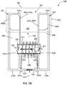
- FIGS. 2A-2Billustrate an exemplary vaporizer cartridge 200 that can be selectively coupled to and removable from a vaporizer body, such as vaporizer body 110 shown in FIGS. 1A-1D ). More specifically, the vaporizer cartridge 200 includes a vaporization chamber 210 having an elongate member 212 that is configured to receive a vaporizable material from a first storage chamber 202 and a second storage chamber 204, and a magnetic element 224 that is configured selectively oscillate between a first position and a second position within the elongate member 212 so as to substantially control the flow of the vaporizable material into the elongate member 212. For purposes of clarity, certain components of the vaporizer cartridge 200 are not illustrated.
- the first storage chamber 202 and the second storage chamber 204are spaced a distance apart from each other such that the first storage chamber 202 and the second storage chamber 204 are each defined by separate walls. That is, the first storage chamber 202 is defined by a first top wall 202a, a first bottom wall 202b that opposes the first top wall 202a, and two opposing first sidewalls 202c, 202d extending therebetween, and the second storage chamber 204 is defined by a second top wall 204a, a second bottom wall 204b that opposes the second top wall 204a, and two opposing second sidewalls 204c, 204d extending therebetween.
- the first storage chamber 202is configured to hold a first fraction of a vaporizable material 206 and the second storage chamber 204 is configured to hold a second fraction of the vaporizable material 208.
- the first fraction of vaporizable material 206 and the second fraction of the vaporizable material 208are collectively referred to herein as "vaporizable material.”
- first and second storage chamber 202, 204can vary, each chamber, as shown in FIGS. 2A-2B , is substantially rectangular.
- the shape and size of the first storage chamber 202 and the second storage chamber 204can also vary with respect to each other. Therefore, the shape and size of the first storage chamber 202 and the second storage chambers 204 are not limited by what is illustrated in FIGS. 2A-2B .
- the first storage chamber 202 and/or the second storage chamber 204can include at least one vent that is configured to substantially allow the passage of air into the respective storage chamber from the environment to thereby substantially maintain an inner pressure (e.g., an inner pressure that is substantially equal to ambient pressure) of the respective storage chamber.
- the at least one ventcan decrease or eliminate any negative pressure that is created as the vaporizable material flows out of the first storage chamber 202 or second storage chamber 204.
- This at least one ventcan be a passive valve or an active valve.
- the vaporization chamber 210includes the elongate member 212 that is configured to receive the vaporizable material from the first storage chamber 202 and the second storage chamber 204. As shown in FIGS. 2A-2B , the elongate member 212 extends from the first storage chamber 202 to the second storage chamber 204.
- the elongate member 212can have a variety of configurations, the elongate member 212, as shown, is substantially cylindrical (e.g., in the form of a tube) and extends from a first end 212a to a second end 212b with a channel 214 extending therebetween.
- the first end 212ais positioned within the first storage chamber 202 and the second end 212b is positioned within the second storage chamber 204 such that the channel 214, and thus the elongate member 212, is in fluid communication with the first and second storage chambers 202, 204.
- the elongate member 212can be formed of any suitable material that is configured to allow vaporized material (aerosol) to pass therethrough.
- the vaporizable material that flows into the elongate member 212is vaporized to form a vaporized material (e.g., an aerosol) by the heat produced by the conductive element 228 in response to either the first electric current and the second electric current.
- a vaporized materiale.g., an aerosol
- Each end of the elongate member 212includes an inlet that is configured to allow the vaporizable material 206 to flow into the channel 214, and thus, the elongate member 212.
- the first end 212aincludes a first inlet 216 and the second end 212b includes a second inlet 218 that allow the vaporizable material to flow into the channel 214 and, thus, into the elongate member 212 from the first storage chamber 202 and the second storage chamber 204, respectively, for vaporization into a vaporized material.
- the first and second inlets 216, 218can have a variety of shapes and/or sizes. For purposes of simplicity, only the first inlet 216 will be discussed herein with respect to size. However, a person skilled in the art will appreciate that the following discussion is equally applicable to the second inlet 218.
- the first inlet 216can have a diameter that is sized to substantially prevent the passage of the first fraction of the vaporizable material 206 therethrough, when an internal pressure of the first storage chamber 202 is substantially equal to ambient pressure outside of the first storage chamber 202. That is, the first inlet 216 can include a diameter that is sized such that a surface tension of the first fraction of the vaporizable material 206 is created to thereby substantially prevent such vaporizable material from passing through, and thus, out of the first storage chamber 202, when the pressure is equalized across the first inlet 216.
- one or more inlet valvescan be positioned at the first end 212a and/or the second end 212b of the elongate member 212.
- the one or more inlet valvescan be configured to substantially prevent the vaporizable material within the channel 214 of the elongate member 212 from flowing back into one of the storage chambers through one of the inlets of the elongate member 212.
- a first inlet valve 220is positioned at the first end 212a of the elongate member 212 to substantially prevent a portion of the first fraction of the vaporizable material 206 in the elongate member 212 from flowing back into the first storage chamber 202.
- a second inlet valve 222is positioned at the second end 212b of the elongate member 212 to substantially prevent a portion of the second fraction of the vaporizable material 208 in the elongate member 212 from flowing back into the second storage chamber 204.
- the first inlet valve 220 and the second inlet valve 222can each substantially function as a one-way valve that are configured to substantially allow an influx of vaporizable material into the elongate member 212 while also being configured to substantially inhibit backflow of the vaporizable material out of the elongate member 212.
- a magnetic element 224is disposed within the channel 214 of the elongate member 212.
- the magnetic element 224is configured to selectively oscillate between a first position (e.g., as shown in 2A), and a second position (e.g., as shown in FIG. 2B ). This oscillation between the first position and the second position can cause the vaporizable material 206 to flow alternately from the first storage chamber 202 and from the second storage chamber 204.
- the magnetic element 224when in the first position ( FIG. 2A ), the magnetic element 224 is configured to substantially prevent the first fraction of the vaporizable material 206 from flowing into the elongate member 212, and when in the second position ( FIG.
- the magnetic element 224is configured to substantially prevent the second fraction of the vaporizable material 208 from flowing into the elongate member 212. As such, the oscillation of the magnetic element 224 substantially controls the delivery of the vaporizable material into the elongate member 212. Further, the magnetic element 224 in combination with the size of the inlets of the elongate member 212 can also control the flow rate of the vaporizable material into the elongate member 212. As a result, a consistent delivery rate of the vaporizable material can be delivered to the vaporization chamber 210 for vaporization.
- the magnetic element 224can have a variety of configurations and sizes. For example, as shown in FIGS. 2A-2B , the magnetic element 224 is substantially rectangular. Further, the magnetic element 224 can be formed of any suitable material that can be magnetized, e.g., iron, nickel, cobalt, and the like. In one embodiment, the magnetic element 224 is a permanent magnet.
- the magnetic element 224moves from the first position to the second position in response to the first motive force and from the second position back to the first position in response to the second motive force.
- the first motive force and the second motive forceare generated by the conductive element 228 in response to the conductive element 228 receiving a first electric current and a second electric current, respectively.
- the conductive element 228can have a variety of configurations that substantially allow the conductive element 228 to be in selective communication with the magnetic element 224 so as to effect oscillation of the magnetic element 224 in response to the first and second motive forces.
- the conductive element 228, as shown in FIGS. 2A-2Bis a conductive coil that is substantially wound about the elongate member 212.
- the conductive element 228can be formed from any suitable electrically and thermally conductive material, such as iron, carbon steel, stainless steel, aluminum, copper, brass, bronze, electrically conductive ceramic and polymer composites, or other materials capable of being inductively heated.
- the conductive element 228is connected to a power source, such as the power source 112 within vaporizer body 110 shown in FIGS. 1A-1D .
- the power sourcewhen prompted (e.g., when a user puffs on a mouthpiece, such as mouthpiece 232 shown in FIGS. 2A-2B ), supplies alternating currents (e.g., the first electric current and the second electric current having a reverse or opposite polarity of the first electric current) to the conductive element 228.
- the vaporizer cartridge 200includes two or more cartridge contacts such as, for example, a first cartridge contact 234a and a second cartridge contact 234b.
- the two or more cartridge contactscan be configured to couple, for example, with the receptacle contacts 125a and 125b in order to form one or more electrical connections with the power source 112.
- the circuit completed by these electrical connectionscan allow delivery of electrical currents to the conductive element 228.
- the conductive element 228In response to the application of alternating currents, the conductive element 228 produces alternating magnetic fields. As such, these alternating magnetic fields act on the magnetic element 224 causing the magnetic element 224 to oscillate from the first position to the second position or vice versa in response to the applied current.
- the conductive element 228when the conductive element 228 receives the first current, which has a first polarity, the conductive element 228 generates a first magnetic field that provides the first motive force to drive the magnetic element 224 from the first position to the second position, and when the conductive element 228 receives the second current, which has a second polarity that is opposite the first polarity, the conductive element 228 generates a second magnetic field that provides the second motive force to drive the magnetic element 224 from the second position to the first position
- the alternating currents applied to the conductive element 228allow the conductive element 228 to produce alternating magnetic fields that drive the magnetic element 224.
- the alternating magnetic fields generated by the conductive element 228pass through the elongate member 212 causing eddy currents. These eddy currents heat the elongate member 212 to a temperature that is at least substantially equal to the vaporization temperature of the vaporizable material. As a result, the portion of the vaporizable material (e.g., a portion of the first fraction of the vaporizable material 206 or of the second fraction of the vaporizable material 208) that flows into the elongate member 212 is then vaporized to form a vaporized material (e.g., aerosol).
- a vaporized materiale.g., aerosol
- This vaporized materialcan then combine with, and be carried out of the vaporization chamber 210, by the air 230 passing through an airflow passageway, such as the airflow passageway 229, of the vaporization chamber 210.
- the conductive element 228can be configured to substantially produce the motive forces to drive the magnetic element 224 to allow flow of the vaporizable material into the elongate member 212 and to substantially vaporize the vaporizable material within the elongate member 212.
- the first and/or second electric current applied to, and received by, the conductive material 228can be adjusted, for example, by the provision of an adjustment mechanism, such as a pulse width modulator, a variable resistor, or the like in an electrical circuit connecting the power source and the conductive element 228.
- an adjustment mechanismsuch as a pulse width modulator, a variable resistor, or the like in an electrical circuit connecting the power source and the conductive element 228.
- the adjustment mechanismincludes a simple on/off switch in the circuit.
- the speed at which the magnetic element 224 oscillatescan be adjusted by adjusting the frequency of the alternating currents.
- a direct currentcan be applied to the conductive element 228 to offset the alternating currents so as to disassociate the heating of the elongate member 212, and thus, the vaporization of the vaporizable material therein, from the oscillation of the magnetic element 224. That is, the application of direct current could stop the oscillation of the magnetic element 224 while heating the elongate member 212.
- the vaporization chamber 210can have a variety of configurations, the vaporization chamber 210, as shown in FIGS. 2A-2B , is defined by two opposing sidewalls 210a, 210b and a bottom wall 210c extending therebetween.
- the first sidewall 210a of the vaporization chamber 210is also one of the sidewalls 202c of the first storage chamber 202
- the second sidewall 210b of the vaporization chamber 210is also one of the sidewalls 202c of the second storage chamber 204.
- the vaporization chamber 210is at least partially bounded by the first and second storage chambers 202, 204.
- the vaporization chamber 210defines an airflow passageway 229 that extends therethrough.
- the airflow passageway 220is configured to direct air, illustrated as dash-lined arrow 230, through the vaporization chamber 210 so that the air 230 will mix with the vaporized material to form an aerosol, illustrated as dash-lined arrow 231.
- the airflow passageway 229further directs the aerosol 231 through an outlet 211 of the vaporization chamber 210, and thus a mouthpiece 232 coupled to the vaporizer cartridge 200, for inhalation by a user. While a mouthpiece 232 is shown in FIGS. 2A-2B , a person skilled in the art will appreciate that in other embodiments, the mouthpiece 232 can be omitted and the user can directly puff on the cartridge 200 at an outlet (such as outlet 211 of vaporization chamber 210).
- At least one wall of the vaporization chamber 210can be formed of, or coated with, a hydrophobic material so as to prevent any condensation from accumulating within the vaporization chamber 210.
- any water that may be present in the aerosol 231 and in the air 230can be carried through and out of the vaporization chamber 210 as the user puffs on the mouthpiece 232.
- the air 230enters the vaporization chamber 210 through the bottom wall 210c as a user puffs the mouthpiece 232.
- the bottom wall 210cis configured to allow air 230 to readily pass therethrough and into the vaporization chamber 210. While the bottom wall 210c can have a variety of configurations, the bottom wall 210c is perforated, as shown in FIGS. 2A-2B . The perforations can be of any suitable size that allows air to pass through the bottom wall 210c.
- the size of the perforationscan substantially prevent any vaporizable material dispensed from the first or second storage chambers 202, 204 or aerosol 231 to pass through the bottom wall 210c, and therefore inhibit undesirable leakage into other portions of a vaporizer body, such as vaporizer body 110 shown in FIGS. 1A-1D , coupled to the vaporizer cartridge 200.
- the bottom wall 210ccan include any suitable number of perforations, and therefore the number of perforations is not limited by what is illustrated in the FIGS. 2A-2B .
- the bottom wall 210ccan be formed of an air permeable material.
- the bottom wall 210cfunctions as an air inlet for the vaporization chamber 210.
- the bottom wall 210ccan also be configured to prevent air 230 and/or aerosol 231 within the vaporization chamber 210 from passing therethrough. That is, the bottom wall 210c can be configured as a one-way valve, and therefore only allow air 230 to pass through and into the vaporization chamber 210. In some embodiments, any of the remaining walls of the vaporization chamber 210 can be perforated and/or formed of an air permeable material to allow air to pass into (or out of) the vaporization chamber 210 as desired.
- the term “substantially”is utilized herein to represent the inherent degree of uncertainty that may be attributed to any quantitative comparison, value, measurement, or other representation.
- the term “substantially”is also utilized herein to represent the degree by which a quantitative representation may vary from a stated reference without resulting in a change in the basic function of the subject matter at issue.
- references to a structure or feature that is disposed "adjacent" another featuremay have portions that overlap or underlie the adjacent feature.
- phrases such as "at least one of' or “one or more of'may occur followed by a conjunctive list of elements or features.
- the term “and/or”may also occur in a list of two or more elements or features. Unless otherwise implicitly or explicitly contradicted by the context in which it used, such a phrase is intended to mean any of the listed elements or features individually or any of the recited elements or features in combination with any of the other recited elements or features.
- the phrases “at least one of A and B;” “one or more of A and B;” and “A and/or B”are each intended to mean "A alone, B alone, or A and B together.”
- a similar interpretationis also intended for lists including three or more items.
- phrases “at least one of A, B, and C;” “one or more of A, B, and C;” and “A, B, and/or C”are each intended to mean “A alone, B alone, C alone, A and B together, A and C together, B and C together, or A and B and C together.”
- Use of the term “based on,” above and in the claimsis intended to mean, “based at least in part on,” such that an unrecited feature or element is also permissible.
- spatially relative termssuch as “forward”, “rearward”, “under”, “below”, “lower”, “over”, “upper” and the like, may be used herein for ease of description to describe one element or feature's relationship to another element(s) or feature(s) as illustrated in the figures. It will be understood that the spatially relative terms are intended to encompass different orientations of the device in use or operation in addition to the orientation depicted in the figures. For example, if a device in the figures is inverted, elements described as “under” or “beneath” other elements or features would then be oriented “over” the other elements or features. Thus, the exemplary term “under” can encompass both an orientation of over and under.
- the devicemay be otherwise oriented (rotated 90 degrees or at other orientations) and the spatially relative descriptors used herein interpreted accordingly.
- the terms “upwardly”, “downwardly”, “vertical”, “horizontal” and the likeare used herein for the purpose of explanation only unless specifically indicated otherwise.
- first and secondmay be used herein to describe various features/elements (including steps), these features/elements should not be limited by these terms, unless the context indicates otherwise. These terms may be used to distinguish one feature/element from another feature/element. Thus, a first feature/element discussed below could be termed a second feature/element, and similarly, a second feature/element discussed below could be termed a first feature/element without departing from the teachings provided herein.
- a numeric valuemay have a value that is +/- 0.1% of the stated value (or range of values), +/- 1% of the stated value (or range of values), +/- 2% of the stated value (or range of values), +/- 5% of the stated value (or range of values), +/- 10% of the stated value (or range of values), etc.
- Any numerical values given hereinshould also be understood to include about or approximately that value, unless the context indicates otherwise. For example, if the value "10" is disclosed, then “about 10" is also disclosed. Any numerical range recited herein is intended to include all sub-ranges subsumed therein.
- One or more aspects or features of the subject matter described hereincan be realized in digital electronic circuitry, integrated circuitry, specially designed application specific integrated circuits (ASICs), field programmable gate arrays (FPGAs) computer hardware, firmware, software, and/or combinations thereof.
- ASICsapplication specific integrated circuits
- FPGAsfield programmable gate arrays
- These various aspects or featurescan include implementation in one or more computer programs that are executable and/or interpretable on a programmable system including at least one programmable processor, which can be special or general purpose, coupled to receive data and instructions from, and to transmit data and instructions to, a storage system, at least one input device, and at least one output device.
- the programmable system or computing systemmay include clients and servers.
- a client and serverare generally remote from each other and typically interact through a communication network. The relationship of client and server arises by virtue of computer programs running on the respective computers and having a client-server relationship to each other.
- machine-readable signalrefers to any signal used to provide machine instructions and/or data to a programmable processor.
- the machine-readable mediumcan store such machine instructions non-transitorily, such as for example as would a non-transient solid-state memory or a magnetic hard drive or any equivalent storage medium.
- the machine-readable mediumcan alternatively or additionally store such machine instructions in a transient manner, such as for example, as would a processor cache or other random access memory associated with one or more physical processor cores.
Landscapes
- Health & Medical Sciences (AREA)
- Engineering & Computer Science (AREA)
- Life Sciences & Earth Sciences (AREA)
- Veterinary Medicine (AREA)
- Heart & Thoracic Surgery (AREA)
- Hematology (AREA)
- Biomedical Technology (AREA)
- Animal Behavior & Ethology (AREA)
- General Health & Medical Sciences (AREA)
- Public Health (AREA)
- Anesthesiology (AREA)
- Pulmonology (AREA)
- Bioinformatics & Cheminformatics (AREA)
- Physics & Mathematics (AREA)
- Electromagnetism (AREA)
- Power Engineering (AREA)
- Biophysics (AREA)
- Catching Or Destruction (AREA)
- Filling Or Discharging Of Gas Storage Vessels (AREA)
- Chemical Vapour Deposition (AREA)
- Disinfection, Sterilisation Or Deodorisation Of Air (AREA)
Description
- This application claims priority to
U.S. Provisional Patent Application No. 62/755,965 filed on November 5, 2018 - The subject matter described herein relates to a cartridge for a vaporizer device and a vaporizer device, including such a vaporizer cartridge.
- Vaporizer devices, which can also be referred to as vaporizers, electronic vaporizer devices, or e-vaporizer devices, can be used for delivery of an aerosol (for example, a vapor-phase and/or condensed-phase material suspended in a stationary or moving mass of air or some other gas carrier) containing one or more active ingredients by inhalation of the aerosol by a user of the vaporizing device. For example, electronic nicotine delivery systems (ENDS) include a class of vaporizer devices that are battery powered and that can be used to simulate the experience of smoking, but without burning of tobacco or other substances. Vaporizer devices are gaining increasing popularity both for prescriptive medical use, in delivering medicaments, and for consumption of tobacco, nicotine, and other plant-based materials. Vaporizer devices can be portable, self-contained, and/or convenient for use.
- In use of a vaporizer device, the user inhales an aerosol, colloquially referred to as "vapor," which can be generated by a heating element that vaporizes (e.g., causes a liquid or solid to at least partially transition to the gas phase) a vaporizable material, which can be liquid, a solution, a solid, a paste, a wax, and/or any other form compatible for use with a specific vaporizer device. The vaporizable material used with a vaporizer device can be provided within a cartridge for example, a separable part of the vaporizer device that contains vaporizable material) that includes an outlet (for example, a mouthpiece) for inhalation of the aerosol by a user.
- To receive the inhalable aerosol generated by a vaporizer device, a user may, in certain examples, activate the vaporizer device by taking a puff, by pressing a button, and/or by some other approach. A puff as used herein can refer to inhalation by the user in a manner that causes a volume of air to be drawn into the vaporizer device such that the inhalable aerosol is generated by a combination of the vaporized vaporizable material with the volume of air.
- An approach by which a vaporizer device generates an inhalable aerosol from a vaporizable material involves heating the vaporizable material in a vaporization chamber (e.g., a heater chamber) to cause the vaporizable material to be converted to the gas (or vapor) phase. A vaporization chamber can refer to an area or volume in the vaporizer device within which a heat source (for example, a conductive, convective, and/or radiative heat source) causes heating of a vaporizable material to produce a mixture of air and vaporized material to form a vapor for inhalation of the vaporizable material by a user of the vaporizer device.
- Vaporizer devices can be controlled by one or more controllers, electronic circuits (for example, sensors, heating elements), and/or the like on the vaporizer device. Vaporizer devices can also wirelessly communicate with an external controller for example, a computing device such as a smartphone).
- In some implementations, the vaporizable material can be drawn out of a reservoir and into the vaporization chamber via a wicking element (e.g., a wick). Drawing of the vaporizable material into the vaporization chamber can be at least partially due to capillary action provided by the wicking element as the wicking element pulls the vaporizable material along the wicking element in the direction of the vaporization chamber. However, as vaporizable material is drawn out of the reservoir, the pressure inside the reservoir is reduced, thereby creating a vacuum and acting against the capillary action. This can reduce the effectiveness of the wicking element to draw the vaporizable material into the vaporization chamber, thereby reducing the effectiveness of the vaporizer device to vaporize a desired amount of vaporizable material, such as when a user takes a puff on the vaporizer device. Furthermore, the vacuum created in the reservoir can ultimately result in the inability to draw all of the vaporizable material into the vaporization chamber, thereby wasting vaporizable material.
- In the prior art according to
US 2018/177240 A1 , a thermal wick for electronic vaporizers is disclosed. Further,US 2018/160735 A1 discloses a wicking system consisting of two plates and a variable spacing between them to allow a control of the liquid flow andUS 2017/0095004 A1 discloses an electronic cigarette with multiple electromagnetic switches. Another vaporizer device is disclosed inUS 2014/069424 that comprises a conventional wick having a first end in contact with a reservoir and a second end in proximity with the heater. As such, improved vaporizer devices and/or vaporization cartridges that improve upon or overcome these issues are desired. - Aspects of the current subject matter relate to vaporizer devices and to cartridges for use in a vaporizer device.
- In some variations, one or more of the following features may optionally be included in any feasible combination.
- According to the claimed invention, a cartridge is provided and includes a first storage chamber and a second storage chamber, a vaporization chamber that includes an elongate member that is in fluid communication with the first storage chamber and the second storage chamber, a magnetic element, and a conductive element in selective communication with the magnetic element. The first storage chamber is configured to hold a first fraction of a vaporizable material and the second storage chamber is configured to hold a second fraction of the vaporizable material. The elongate member extends from a first end to a second end with a channel extending therebetween, and the elongate member is configured to receive the vaporizable material. The magnetic element is disposed within the channel of the elongate member. The magnetic element is configured to selectively oscillate between a first position and a second position so as to substantially control the flow of the vaporizable material into the elongate member. The conductive element is configured to generate a first motive force in response to receiving a first electric current to drive the magnetic element from the first position to the second position and is configured to generate a second motive force in response to receiving a second electric current to drive the magnetic element from the second position to the first position, in which the second direction is opposite of the first direction. The conductive element is further configured to substantially vaporize the vaporizable material within the elongate member to a vaporized material in response to receiving the first electric current and in response to receiving the second electric current.
- The conductive element can have a variety of configurations. For example, in some embodiments, the conductive element can be a coil that is substantially wound about at least a portion of the elongate member. In some embodiments, the conductive element can be configured to produce an alternating magnetic field.
- In some embodiments, the first electric current can have a first polarity and the second electric current can have a second polarity that is opposite the first polarity.
- In some embodiments, when in the first position, the magnetic element can be configured to prevent the first fraction of the vaporizable material from flowing into the elongate member, and when in the second position, the magnetic element can be configured to prevent the second fraction of the vaporizable material from flowing into the elongate member. In certain embodiments, a portion of the first fraction of the vaporizable material can flow into the elongate member when the magnetic element is in the second position. In such embodiments, an inlet valve can be positioned at the first end of the elongate member, in which the inlet valve can be configured to substantially prevent backflow of the portion of the first fraction of the vaporizable material from the elongate member and into the first storage chamber. In certain embodiments, a portion of the second fraction of the vaporizable material can flow into the elongate member when the magnetic element is in the first position. In such embodiments, an inlet valve can be positioned at the second end of the elongate member, in which the inlet valve can be configured to substantially prevent backflow of the portion of the second fraction of the vaporizable material from the elongate member and into the second storage chamber.
- The magnetic element can have a variety of configurations. For example, in some embodiments, the magnetic element can be a permanent magnet.
- The vaporization chamber can have a variety of configurations. For example, in some embodiments, the vaporization chamber can define an airflow passageway that extends therethrough. The airflow passageway can be configured to allow the vaporized material to combine with an influx of air such that the vaporized material passes out of the vaporization chamber.
- In another embodiment, a vaporizer device is provided and includes a vaporizer body and a cartridge according to claim 1.
- The vaporizer body can have a variety of configurations. For example, in some embodiments, the vaporizer body can include a power source.
- The details of one or more variations of the subject matter described herein are set forth in the accompanying drawings and the description below. Other features and advantages of the subject matter described herein will be apparent from the description and drawings, and from the claims. The claims that follow this disclosure are intended to define the scope of the protected subject matter.
- The accompanying drawings, which are incorporated into and constitute a part of this specification, show certain aspects of the subject matter disclosed herein and, together with the description, help explain some of the principles associated with the disclosed implementations. In the drawings:
FIG. 1A is a block diagram of a vaporizer device;- FIG. IB is a top view of an embodiment of a vaporizer device, showing a vaporizer cartridge separated from a vaporizer device body;
FIG. 1C is a top view of the vaporizer device ofFIG. 1B , showing the vaporizer cartridge coupled to the vaporizer device body;- FIG. ID is a perspective view of the vaporizer device of
FIG. 1C ; - FIG. IE is a perspective view of the vaporizer cartridge of
FIG. 1B ; - FIG. IF is another perspective view of the vaporizer cartridge of FIG. IE;
FIG. 2A illustrates a schematic of another embodiment of a vaporizer cartridge, the vaporizer cartridge having a magnetic element, showing the magnetic element in a first position; andFIG. 2B illustrates the vaporizer cartridge ofFIG. 2A , showing the magnetic element in a second position.- When practical, similar reference numbers denote similar structures, features, or elements.
- Implementations of the current subject matter include methods, apparatuses, articles of manufacture, and systems relating to vaporization of one or more materials for inhalation by a user. Example implementations include vaporizer devices and systems including vaporizer devices. The term "vaporizer device" as used in the following description and claims refers to any of a self-contained apparatus, an apparatus that includes two or more separable parts (for example, a vaporizer body that includes a battery and other hardware, and a cartridge that includes a vaporizable material), and/or the like. A "vaporizer system," as used herein, can include one or more components, such as a vaporizer device. Examples of vaporizer devices consistent with implementations of the current subject matter include electronic vaporizers, electronic nicotine delivery systems (ENDS), and/or the like. In general, such vaporizer devices are hand-held devices that heat (such as by convection, conduction, radiation, and/or some combination thereof) a vaporizable material to provide an inhalable dose of the material.
- The vaporizable material used with a vaporizer device can be provided within a cartridge (for example, a part of the vaporizer device that contains the vaporizable material in a reservoir or other container) which can be refillable when empty, or disposable such that a new cartridge containing additional vaporizable material of a same or different type can be used). A vaporizer device can be a cartridge-using vaporizer device, a cartridge-less vaporizer device, or a multi-use vaporizer device capable of use with or without a cartridge. For example, a vaporizer device can include a heating chamber (for example, an oven or other region in which material is heated by a heating element) configured to receive a vaporizable material directly into the heating chamber, and/or a reservoir or the like for containing the vaporizable material.
- In some implementations, a vaporizer device can be configured for use with a liquid vaporizable material (for example, a carrier solution in which an active and/or inactive ingredient(s) are suspended or held in solution, or a liquid form of the vaporizable material itself). The liquid vaporizable material can be capable of being completely vaporized. Alternatively, at least a portion of the liquid vaporizable material can remain after all of the material suitable for inhalation has been vaporized.
- Referring to the block diagram of
FIG. 1A , avaporizer device 100 can include a power source 112 (for example, a battery, which can be a rechargeable battery), and a controller 104 (for example, a processor, circuitry, etc. capable of executing logic) for controlling delivery of heat to anatomizer 141 to cause avaporizable material 102 to be converted from a condensed form (such as a liquid, a solution, a suspension, a part of an at least partially unprocessed plant material, etc.) to the gas phase. Thecontroller 104 can be part of one or more printed circuit boards (PCBs) consistent with certain implementations of the current subject matter. - After conversion of the
vaporizable material 102 to the gas phase, at least some of thevaporizable material 102 in the gas phase can condense to form particulate matter in at least a partial local equilibrium with the gas phase as part of an aerosol, which can form some or all of an inhalable dose provided by thevaporizer device 100 during a user's puff or draw on thevaporizer device 100. It should be appreciated that the interplay between gas and condensed phases in an aerosol generated by avaporizer device 100 can be complex and dynamic, due to factors such as ambient temperature, relative humidity, chemistry, flow conditions in airflow paths (both inside the vaporizer device and in the airways of a human or other animal), and/or mixing of thevaporizable material 102 in the gas phase or in the aerosol phase with other air streams, which can affect one or more physical parameters of an aerosol. In some vaporizer devices, and particularly for vaporizer devices configured for delivery of volatile vaporizable materials, the inhalable dose can exist predominantly in the gas phase (for example, formation of condensed phase particles can be very limited). - The
atomizer 141 in thevaporizer device 100 can be configured to vaporize avaporizable material 102. Thevaporizable material 102 can be a liquid. Examples of thevaporizable material 102 include neat liquids, suspensions, solutions, mixtures, and/or the like. Theatomizer 141 can include a wicking element (i.e., a wick) configured to convey an amount of thevaporizable material 102 to a part of theatomizer 141 that includes a heating element (not shown inFIG. 1A ). - For example, the wicking element can be configured to draw the
vaporizable material 102 from areservoir 140 configured to contain thevaporizable material 102, such that thevaporizable material 102 can be vaporized by heat delivered from a heating element. The wicking element can also optionally allow air to enter thereservoir 140 and replace the volume ofvaporizable material 102 removed. In some implementations of the current subject matter, capillary action can pullvaporizable material 102 into the wick for vaporization by the heating element, and air can return to thereservoir 140 through the wick to at least partially equalize pressure in thereservoir 140. Other methods of allowing air back into thereservoir 140 to equalize pressure are also within the scope of the current subject matter. - As used herein, the terms "wick" or "wicking element" include any material capable of causing fluid motion via capillary pressure.
- The heating element can include one or more of a conductive heater, a radiative heater, and/or a convective heater. One type of heating element is a resistive heating element, which can include a material (such as a metal or alloy, for example a nickel-chromium alloy, or a non-metallic resistor) configured to dissipate electrical power in the form of heat when electrical current is passed through one or more resistive segments of the heating element. In some implementations of the current subject matter, the
atomizer 141 can include a heating element which includes a resistive coil or other heating element wrapped around, positioned within, integrated into a bulk shape of, pressed into thermal contact with, or otherwise arranged to deliver heat to a wicking element, to cause thevaporizable material 102 drawn from thereservoir 140 by the wicking element to be vaporized for subsequent inhalation by a user in a gas and/or a condensed (for example, aerosol particles or droplets) phase. Other wicking elements, heating elements, and/or atomizer assembly configurations are also possible. - The heating element can be activated in association with a user puffing (i.e., drawing, inhaling, etc.) on a
mouthpiece 130 of thevaporizer device 100 to cause air to flow from an air inlet, along an airflow path that passes the atomizer 141 (i.e., wicking element and heating element). Optionally, air can flow from an air inlet through one or more condensation areas or chambers, to an air outlet in themouthpiece 130. Incoming air moving along the airflow path moves over or through theatomizer 141, wherevaporizable material 102 in the gas phase is entrained into the air. The heating element can be activated via thecontroller 104, which can optionally be a part of avaporizer body 110 as discussed herein, causing current to pass from thepower source 112 through a circuit including the resistive heating element, which is optionally part of avaporizer cartridge 120 as discussed herein. As noted herein, the entrainedvaporizable material 102 in the gas phase can condense as it passes through the remainder of the airflow path such that an inhalable dose of thevaporizable material 102 in an aerosol form can be delivered from the air outlet (for example, the mouthpiece 130) for inhalation by a user. - Activation of the heating element can be caused by automatic detection of a puff based on one or more signals generated by one or more of a
sensor 113. Thesensor 113 and the signals generated by thesensor 113 can include one or more of: a pressure sensor or sensors disposed to detect pressure along the airflow path relative to ambient pressure (or optionally to measure changes in absolute pressure), a motion sensor or sensors (for example, an accelerometer) of thevaporizer device 100, a flow sensor or sensors of thevaporizer device 100, a capacitive lip sensor of thevaporizer device 100, detection of interaction of a user with thevaporizer device 100 via one or more input devices 116 (for example, buttons or other tactile control devices of the vaporizer device 100), receipt of signals from a computing device in communication with thevaporizer device 100, and/or via other approaches for determining that a puff is occurring or imminent. - As discussed herein, the
vaporizer device 100 consistent with implementations of the current subject matter can be configured to connect (such as, for example, wirelessly or via a wired connection) to a computing device (or optionally two or more devices) in communication with thevaporizer device 100. To this end, thecontroller 104 can includecommunication hardware 105. Thecontroller 104 can also include amemory 108. Thecommunication hardware 105 can include firmware and/or can be controlled by software for executing one or more cryptographic protocols for the communication. - A computing device can be a component of a vaporizer system that also includes the
vaporizer device 100, and can include its own hardware for communication, which can establish a wireless communication channel with thecommunication hardware 105 of thevaporizer device 100. For example, a computing device used as part of a vaporizer system can include a general-purpose computing device (such as a smartphone, a tablet, a personal computer, some other portable device such as a smartwatch, or the like) that executes software to produce a user interface for enabling a user to interact with thevaporizer device 100. In other implementations of the current subject matter, such a device used as part of a vaporizer system can be a dedicated piece of hardware such as a remote control or other wireless or wired device having one or more physical or soft (i.e., configurable on a screen or other display device and selectable via user interaction with a touch-sensitive screen or some other input device like a mouse, pointer, trackball, cursor buttons, or the like) interface controls. Thevaporizer device 100 can also include one ormore outputs 117 or devices for providing information to the user. For example, theoutputs 117 can include one or more light emitting diodes (LEDs) configured to provide feedback to a user based on a status and/or mode of operation of thevaporizer device 100. - In the example in which a computing device provides signals related to activation of the resistive heating element, or in other examples of coupling of a computing device with the
vaporizer device 100 for implementation of various control or other functions, the computing device executes one or more computer instruction sets to provide a user interface and underlying data handling. In one example, detection by the computing device of user interaction with one or more user interface elements can cause the computing device to signal thevaporizer device 100 to activate the heating element to reach an operating temperature for creation of an inhalable dose of vapor/aerosol. Other functions of thevaporizer device 100 can be controlled by interaction of a user with a user interface on a computing device in communication with thevaporizer device 100. - The temperature of a resistive heating element of the
vaporizer device 100 can depend on a number of factors, including an amount of electrical power delivered to the resistive heating element and/or a duty cycle at which the electrical power is delivered, conductive heat transfer to other parts of theelectronic vaporizer device 100 and/or to the environment, latent heat losses due to vaporization of thevaporizable material 102 from the wicking element and/or theatomizer 141 as a whole, and convective heat losses due to airflow (i.e., air moving across the heating element or theatomizer 141 as a whole when a user inhales on the vaporizer device 100). As noted herein, to reliably activate the heating element or heat the heating element to a desired temperature, thevaporizer device 100 may, in some implementations of the current subject matter, make use of signals from the sensor 113 (for example, a pressure sensor) to determine when a user is inhaling. Thesensor 113 can be positioned in the airflow path and/or can be connected (for example, by a passageway or other path) to an airflow path containing an inlet for air to enter thevaporizer device 100 and an outlet via which the user inhales the resulting vapor and/or aerosol such that thesensor 113 experiences changes (for example, pressure changes) concurrently with air passing through thevaporizer device 100 from the air inlet to the air outlet. In some implementations of the current subject matter, the heating element can be activated in association with a user's puff, for example by automatic detection of the puff, or by thesensor 113 detecting a change (.such as a pressure change) in the airflow path. - The
sensor 113 can be positioned on or coupled to (i.e., electrically or electronically connected, either physically or via a wireless connection) the controller 104 (for example, a printed circuit board assembly or other type of circuit board). To take measurements accurately and maintain durability of thevaporizer device 100, it can be beneficial to provide aseal 127 resilient enough to separate an airflow path from other parts of thevaporizer device 100. Theseal 127, which can be a gasket, can be configured to at least partially surround thesensor 113 such that connections of thesensor 113 to the internal circuitry of thevaporizer device 100 are separated from a part of thesensor 113 exposed to the airflow path. In an example of a cartridge-based vaporizer device, theseal 127 can also separate parts of one or more electrical connections between thevaporizer body 110 and thevaporizer cartridge 120. Such arrangements of theseal 127 in thevaporizer device 100 can be helpful in mitigating against potentially disruptive impacts on vaporizer components resulting from interactions with environmental factors such as water in the vapor or liquid phases, other fluids such as thevaporizable material 102, etc., and/or to reduce the escape of air from the designated airflow path in thevaporizer device 100. Unwanted air, liquid or other fluid passing and/or contacting circuitry of thevaporizer device 100 can cause various unwanted effects, such as altered pressure readings, and/or can result in the buildup of unwanted material, such as moisture, excessvaporizable material 102, etc., in parts of thevaporizer device 100 where they can result in poor pressure signal, degradation of thesensor 113 or other components, and/or a shorter life of thevaporizer device 100. Leaks in theseal 127 can also result in a user inhaling air that has passed over parts of thevaporizer device 100 containing, or constructed of, materials that may not be desirable to be inhaled. - In some implementations, the
vaporizer body 110 includes thecontroller 104, the power source 112 (for example, a battery), one more of thesensor 113, charging contacts (such as those for charging the power source 112), theseal 127, and acartridge receptacle 118 configured to receive thevaporizer cartridge 120 for coupling with thevaporizer body 110 through one or more of a variety of attachment structures. In some examples, thevaporizer cartridge 120 includes thereservoir 140 for containing thevaporizable material 102, and themouthpiece 130 has an aerosol outlet for delivering an inhalable dose to a user. Thevaporizer cartridge 120 can include theatomizer 141 having a wicking element and a heating element. Alternatively, one or both of the wicking element and the heating element can be part of thevaporizer body 110. In implementations in which any part of the atomizer 141 (i.e., heating element and/or wicking element) is part of thevaporizer body 110, thevaporizer device 100 can be configured to supplyvaporizable material 102 from thereservoir 140 in thevaporizer cartridge 120 to the part(s) of theatomizer 141 included in thevaporizer body 110. - In an embodiment of the
vaporizer device 100 in which thepower source 112 is part of thevaporizer body 110, and a heating element is disposed in thevaporizer cartridge 120 and configured to couple with thevaporizer body 110, thevaporizer device 100 can include electrical connection features (for example, means for completing a circuit) for completing a circuit that includes the controller 104 (for example, a printed circuit board, a microcontroller, or the like), thepower source 112, and the heating element (for example, a heating element within the atomizer 141). These features can include one or more contacts (referred to herein ascartridge contacts vaporizer cartridge 120 and at least two contacts (referred to herein asreceptacle contacts 125a and 125b) disposed near a base of thecartridge receptacle 118 of thevaporizer device 100 such that thecartridge contacts receptacle contacts 125a and 125b make electrical connections when thevaporizer cartridge 120 is inserted into and coupled with thecartridge receptacle 118. The circuit completed by these electrical connections can allow delivery of electrical current to a heating element and can further be used for additional functions, such as measuring a resistance of the heating element for use in determining and/or controlling a temperature of the heating element based on a thermal coefficient of resistivity of the heating element. - In some implementations of the current subject matter, the
cartridge contacts receptacle contacts 125a and 125b can be configured to electrically connect in either of at least two orientations. In other words, one or more circuits necessary for operation of thevaporizer device 100 can be completed by insertion of thevaporizer cartridge 120 into thecartridge receptacle 118 in a first rotational orientation (around an axis along which thevaporizer cartridge 120 is inserted into thecartridge receptacle 118 of the vaporizer body 110) such that thecartridge contact 124a is electrically connected to the receptacle contact 125a and thecartridge contact 124b is electrically connected to thereceptacle contact 125b. Furthermore, the one or more circuits necessary for operation of thevaporizer device 100 can be completed by insertion of thevaporizer cartridge 120 in thecartridge receptacle 118 in a second rotational orientationsuch cartridge contact 124a is electrically connected to thereceptacle contact 125b andcartridge contact 124b is electrically connected to the receptacle contact 125a. - For example, the
vaporizer cartridge 120 or at least theinsertable end 122 of thevaporizer cartridge 120 can be symmetrical upon a rotation of 180° around an axis along which thevaporizer cartridge 120 is inserted into thecartridge receptacle 118. In such a configuration, the circuitry of thevaporizer device 100 can support identical operation regardless of which symmetrical orientation of thevaporizer cartridge 120 occurs. - In one example of an attachment structure for coupling the
vaporizer cartridge 120 to thevaporizer body 110, thevaporizer body 110 includes one or more detents (for example, dimples, protrusions, etc.) protruding inwardly from an inner surface of thecartridge receptacle 118, additional material (such as metal, plastic, etc.) formed to include a portion protruding into thecartridge receptacle 118, and/or the like. One or more exterior surfaces of thevaporizer cartridge 120 can include corresponding recesses (not shown inFIG. 1A ) that can fit and/or otherwise snap over such detents or protruding portions when thevaporizer cartridge 120 is inserted into thecartridge receptacle 118 on thevaporizer body 110. When thevaporizer cartridge 120 and thevaporizer body 110 are coupled (e.g., by insertion of thevaporizer cartridge 120 into thecartridge receptacle 118 of the vaporizer body 110), the detents or protrusions of thevaporizer body 110 can fit within and/or otherwise be held within the recesses of thevaporizer cartridge 120, to hold thevaporizer cartridge 120 in place when assembled. Such an assembly can provide enough support to hold thevaporizer cartridge 120 in place to ensure good contact between thecartridge contacts receptacle contacts 125a and 125b, while allowing release of thevaporizer cartridge 120 from thevaporizer body 110 when a user pulls with reasonable force on thevaporizer cartridge 120 to disengage thevaporizer cartridge 120 from thecartridge receptacle 118. - In some implementations, the
vaporizer cartridge 120, or at least aninsertable end 122 of thevaporizer cartridge 120 configured for insertion in thecartridge receptacle 118, can have a non-circular cross section transverse to the axis along which thevaporizer cartridge 120 is inserted into thecartridge receptacle 118. For example, the non-circular cross section can be approximately rectangular, approximately elliptical (i.e., have an approximately oval shape), non-rectangular but with two sets of parallel or approximately parallel opposing sides (i.e., having a parallelogram-like shape), or other shapes having rotational symmetry of at least order two. In this context, approximate shape indicates that a basic likeness to the described shape is apparent, but that sides of the shape in question need not be completely linear and vertices need not be completely sharp. Rounding of both or either of the edges or the vertices of the cross-sectional shape is contemplated in the description of any non-circular cross section referred to herein. - The
cartridge contacts receptacle contacts 125a and 125b can take various forms. For example, one or both sets of contacts can include conductive pins, tabs, posts, receiving holes for pins or posts, or the like. Some types of contacts can include springs or other features to facilitate better physical and electrical contact between the contacts on thevaporizer cartridge 120 and thevaporizer body 110. The electrical contacts can optionally be gold-plated, and/or include other materials. FIGS. 1B-1D illustrate an embodiment of thevaporizer body 110 having acartridge receptacle 118 into which thevaporizer cartridge 120 can be releasably inserted.FIGS. 1B and 1C show top views of thevaporizer device 100 illustrating thevaporizer cartridge 120 being positioned for insertion and inserted, respectively, into thevaporizer body 110.FIG. 1D illustrates thereservoir 140 of thevaporizer cartridge 120 being formed in whole or in part from translucent material such that a level of thevaporizable material 102 is visible from a window 132 (e.g., translucent material) along thevaporizer cartridge 120. Thevaporizer cartridge 120 can be configured such that thewindow 132 remains visible when insertably received by thevaporizer cartridge receptacle 118 of thevaporizer body 110. For example, in one exemplary configuration, thewindow 132 can be disposed between a bottom edge of themouthpiece 130 and a top edge of thevaporizer body 110 when thevaporizer cartridge 120 is coupled with thecartridge receptacle 118.- FIG. IE illustrates an
example airflow path 134 created during a puff by a user on thevaporizer device 100. Theairflow path 134 can direct air to a vaporization chamber 150 (see FIG. IF) contained in a wick housing where the air is combined with inhalable aerosol for delivery to a user via amouthpiece 130, which can also be part of thevaporizer cartridge 120. For example, when a user puffs on thevaporizer device 100device 100, air can pass between an outer surface of the vaporizer cartridge 120 (for example,window 132 shown in FIG. ID) and an inner surface of thecartridge receptacle 118 on thevaporizer body 110. Air can then be drawn into theinsertable end 122 of thevaporizer cartridge 120, through thevaporization chamber 150 that includes or contains the heating element and wick, and out through anoutlet 136 of themouthpiece 130 for delivery of the inhalable aerosol to a user. - As shown in FIG. IE, this configuration causes air to flow down around the
insertable end 122 of thevaporizer cartridge 120 into thecartridge receptacle 118 and then flow back in the opposite direction after passing around the insertable end 122 (e.g., an end opposite of the end including the mouthpiece 130) of thevaporizer cartridge 120 as it enters into the cartridge body toward thevaporization chamber 150. Theairflow path 134 then travels through the interior of thevaporizer cartridge 120, for example via one or more tubes or internal channels (such ascannula 128 shown inFIG. 1F ) and through one or more outlets (such as outlet 136) formed in themouthpiece 130. Themouthpiece 130 can be a separable component of thevaporizer cartridge 120 or can be integrally formed with other component(s) of the vaporizer cartridge 120 (for example, formed as a unitary structure with thereservoir 140 and/or the like). - FIG. IF shows additional features that can be included in the
vaporizer cartridge 120 consistent with implementations of the current subject matter. For example, thevaporizer cartridge 120 can include a plurality of cartridge contacts (such ascartridge contacts insertable end 122. Thecartridge contacts vaporizer cartridge 120. FIG. IF also shows thecannula 128 within thevaporizer cartridge 120 that defines part of theairflow path 134 between the heating chamber formed between theconductive structure 126 and themouthpiece 130. - As mentioned above, existing cartridges can include a wicking element that is generally configured to withdraw a vaporizable material from a reservoir housing such that the vaporizable material may be subsequently vaporized (e.g., by exposing the withdrawn vaporizable material to heat provided by a heating element). This withdrawing of the vaporizable material from the reservoir housing can be due, at least in part, to capillary action provided by the wick, which pulls the vaporizable material along the wick in the direction towards a vaporization chamber. As a result, the vaporizable material is fed into the wicking element by capillary action. However, the magnitude of capillary action can be at least partially contingent upon the wicking material itself (e.g., the type of wicking material, the dimensions of the wicking material (e.g., length), the absorption rate of the wicking material) and on the amount of vaporizable material contained within reservoir housing to replenish the wicking element. As a result, a consistent feed rate of vaporizable material into the vaporization chamber may be difficult to achieve and/or maintain due to changes in the magnitude of the capillary action present in the wick.
- Under such circumstances, the effectiveness of the vaporization device to vaporize a desired amount of vaporizable material, such as when a user takes a puff on the vaporizer device, can be reduced. Various features and devices are described below that improve upon or overcome these issues. For example, various features are described herein that replace the wicking element with a pumping mechanism that is configured to pump the vaporizable material from the reservoir housing and into a vaporization chamber at a controlled feed rate. Implementing a pumping mechanism, as opposed to using a wicking element, may provide advantages and improvements relative to existing approaches, while also introducing additional benefits, as described herein.
- The vaporizer cartridges described herein allow for controlled delivery of vaporizable material from a reservoir housing at a consistent feed rate. The vaporizer cartridges generally include a first storage chamber and a second storage chamber, each having vaporizable material disposed therein. The vaporizer cartridge further includes a vaporization chamber having an elongate member in fluid communication with the first storage chamber and the second storage chamber. As discussed in more detail below, a magnetic element is disposed within the elongate member and configured to selectively oscillate between a first position and a second position so as to substantially control the flow rate of the vaporizable material into the elongate member for vaporization. The magnetic element moves from the first position to the second position in response to a first motive force and from the second position back to the first position in response to a second motive force. These motive forces are generated by a conductive element that is in communication with the magnetic element. The conductive element is also configured to vaporize the vaporizable material within the elongate member. As such, the conductive element can be configured to produce the motive forces to oscillate the magnetic element as well as the heat needed to vaporize the vaporizable material.
FIGS. 2A-2B illustrate anexemplary vaporizer cartridge 200 that can be selectively coupled to and removable from a vaporizer body, such asvaporizer body 110 shown inFIGS. 1A-1D ). More specifically, thevaporizer cartridge 200 includes avaporization chamber 210 having anelongate member 212 that is configured to receive a vaporizable material from afirst storage chamber 202 and asecond storage chamber 204, and amagnetic element 224 that is configured selectively oscillate between a first position and a second position within theelongate member 212 so as to substantially control the flow of the vaporizable material into theelongate member 212. For purposes of clarity, certain components of thevaporizer cartridge 200 are not illustrated.- As shown, the
first storage chamber 202 and thesecond storage chamber 204 are spaced a distance apart from each other such that thefirst storage chamber 202 and thesecond storage chamber 204 are each defined by separate walls. That is, thefirst storage chamber 202 is defined by a firsttop wall 202a, a firstbottom wall 202b that opposes the firsttop wall 202a, and two opposingfirst sidewalls second storage chamber 204 is defined by a secondtop wall 204a, a secondbottom wall 204b that opposes the secondtop wall 204a, and two opposingsecond sidewalls first storage chamber 202 is configured to hold a first fraction of avaporizable material 206 and thesecond storage chamber 204 is configured to hold a second fraction of thevaporizable material 208. The first fraction ofvaporizable material 206 and the second fraction of thevaporizable material 208 are collectively referred to herein as "vaporizable material." - While the shape and size of the first and
second storage chamber FIGS. 2A-2B , is substantially rectangular. The shape and size of thefirst storage chamber 202 and thesecond storage chamber 204 can also vary with respect to each other. Therefore, the shape and size of thefirst storage chamber 202 and thesecond storage chambers 204 are not limited by what is illustrated inFIGS. 2A-2B . Further, thefirst storage chamber 202 and/or thesecond storage chamber 204 can include at least one vent that is configured to substantially allow the passage of air into the respective storage chamber from the environment to thereby substantially maintain an inner pressure (e.g., an inner pressure that is substantially equal to ambient pressure) of the respective storage chamber. As such, the at least one vent can decrease or eliminate any negative pressure that is created as the vaporizable material flows out of thefirst storage chamber 202 orsecond storage chamber 204. This at least one vent can be a passive valve or an active valve. - In general, as discussed above, the
vaporization chamber 210 includes theelongate member 212 that is configured to receive the vaporizable material from thefirst storage chamber 202 and thesecond storage chamber 204. As shown inFIGS. 2A-2B , theelongate member 212 extends from thefirst storage chamber 202 to thesecond storage chamber 204. - While the
elongate member 212 can have a variety of configurations, theelongate member 212, as shown, is substantially cylindrical (e.g., in the form of a tube) and extends from afirst end 212a to asecond end 212b with achannel 214 extending therebetween. Thefirst end 212a is positioned within thefirst storage chamber 202 and thesecond end 212b is positioned within thesecond storage chamber 204 such that thechannel 214, and thus theelongate member 212, is in fluid communication with the first andsecond storage chambers elongate member 212 can be formed of any suitable material that is configured to allow vaporized material (aerosol) to pass therethrough. As discussed in more detail below, the vaporizable material that flows into theelongate member 212 is vaporized to form a vaporized material (e.g., an aerosol) by the heat produced by theconductive element 228 in response to either the first electric current and the second electric current. - Each end of the
elongate member 212 includes an inlet that is configured to allow thevaporizable material 206 to flow into thechannel 214, and thus, theelongate member 212. As shown inFIGS. 2A-2B , thefirst end 212a includes afirst inlet 216 and thesecond end 212b includes asecond inlet 218 that allow the vaporizable material to flow into thechannel 214 and, thus, into theelongate member 212 from thefirst storage chamber 202 and thesecond storage chamber 204, respectively, for vaporization into a vaporized material. - The first and
second inlets first inlet 216 will be discussed herein with respect to size. However, a person skilled in the art will appreciate that the following discussion is equally applicable to thesecond inlet 218. - For example, the
first inlet 216 can have a diameter that is sized to substantially prevent the passage of the first fraction of thevaporizable material 206 therethrough, when an internal pressure of thefirst storage chamber 202 is substantially equal to ambient pressure outside of thefirst storage chamber 202. That is, thefirst inlet 216 can include a diameter that is sized such that a surface tension of the first fraction of thevaporizable material 206 is created to thereby substantially prevent such vaporizable material from passing through, and thus, out of thefirst storage chamber 202, when the pressure is equalized across thefirst inlet 216. - Further, in some embodiments, one or more inlet valves can be positioned at the
first end 212a and/or thesecond end 212b of theelongate member 212. The one or more inlet valves can be configured to substantially prevent the vaporizable material within thechannel 214 of theelongate member 212 from flowing back into one of the storage chambers through one of the inlets of theelongate member 212. For example, as shown inFIGS. 2A-2B , afirst inlet valve 220 is positioned at thefirst end 212a of theelongate member 212 to substantially prevent a portion of the first fraction of thevaporizable material 206 in theelongate member 212 from flowing back into thefirst storage chamber 202. As further shown inFIGS. 2A-2B , asecond inlet valve 222 is positioned at thesecond end 212b of theelongate member 212 to substantially prevent a portion of the second fraction of thevaporizable material 208 in theelongate member 212 from flowing back into thesecond storage chamber 204. As such, thefirst inlet valve 220 and thesecond inlet valve 222 can each substantially function as a one-way valve that are configured to substantially allow an influx of vaporizable material into theelongate member 212 while also being configured to substantially inhibit backflow of the vaporizable material out of theelongate member 212. - As discussed above, a
magnetic element 224 is disposed within thechannel 214 of theelongate member 212. Themagnetic element 224 is configured to selectively oscillate between a first position (e.g., as shown in 2A), and a second position (e.g., as shown inFIG. 2B ). This oscillation between the first position and the second position can cause thevaporizable material 206 to flow alternately from thefirst storage chamber 202 and from thesecond storage chamber 204. For example, when in the first position (FIG. 2A ), themagnetic element 224 is configured to substantially prevent the first fraction of thevaporizable material 206 from flowing into theelongate member 212, and when in the second position (FIG. 2B ), themagnetic element 224 is configured to substantially prevent the second fraction of thevaporizable material 208 from flowing into theelongate member 212. As such, the oscillation of themagnetic element 224 substantially controls the delivery of the vaporizable material into theelongate member 212. Further, themagnetic element 224 in combination with the size of the inlets of theelongate member 212 can also control the flow rate of the vaporizable material into theelongate member 212. As a result, a consistent delivery rate of the vaporizable material can be delivered to thevaporization chamber 210 for vaporization. - The
magnetic element 224 can have a variety of configurations and sizes. For example, as shown inFIGS. 2A-2B , themagnetic element 224 is substantially rectangular. Further, themagnetic element 224 can be formed of any suitable material that can be magnetized, e.g., iron, nickel, cobalt, and the like. In one embodiment, themagnetic element 224 is a permanent magnet. - As discussed above, in use, the
magnetic element 224 moves from the first position to the second position in response to the first motive force and from the second position back to the first position in response to the second motive force. The first motive force and the second motive force are generated by theconductive element 228 in response to theconductive element 228 receiving a first electric current and a second electric current, respectively. - The
conductive element 228 can have a variety of configurations that substantially allow theconductive element 228 to be in selective communication with themagnetic element 224 so as to effect oscillation of themagnetic element 224 in response to the first and second motive forces. For example, theconductive element 228, as shown inFIGS. 2A-2B , is a conductive coil that is substantially wound about theelongate member 212. Theconductive element 228 can be formed from any suitable electrically and thermally conductive material, such as iron, carbon steel, stainless steel, aluminum, copper, brass, bronze, electrically conductive ceramic and polymer composites, or other materials capable of being inductively heated. - The
conductive element 228 is connected to a power source, such as thepower source 112 withinvaporizer body 110 shown inFIGS. 1A-1D . The power source, when prompted (e.g., when a user puffs on a mouthpiece, such asmouthpiece 232 shown inFIGS. 2A-2B ), supplies alternating currents (e.g., the first electric current and the second electric current having a reverse or opposite polarity of the first electric current) to theconductive element 228. For example, in some embodiments, thevaporizer cartridge 200 includes two or more cartridge contacts such as, for example, afirst cartridge contact 234a and asecond cartridge contact 234b. The two or more cartridge contacts can be configured to couple, for example, with thereceptacle contacts 125a and 125b in order to form one or more electrical connections with thepower source 112. The circuit completed by these electrical connections can allow delivery of electrical currents to theconductive element 228. - In response to the application of alternating currents, the
conductive element 228 produces alternating magnetic fields. As such, these alternating magnetic fields act on themagnetic element 224 causing themagnetic element 224 to oscillate from the first position to the second position or vice versa in response to the applied current. That is, in use, when theconductive element 228 receives the first current, which has a first polarity, theconductive element 228 generates a first magnetic field that provides the first motive force to drive themagnetic element 224 from the first position to the second position, and when theconductive element 228 receives the second current, which has a second polarity that is opposite the first polarity, theconductive element 228 generates a second magnetic field that provides the second motive force to drive themagnetic element 224 from the second position to the first position Thus, the alternating currents applied to theconductive element 228 allow theconductive element 228 to produce alternating magnetic fields that drive themagnetic element 224. - Further, the alternating magnetic fields generated by the
conductive element 228 pass through theelongate member 212 causing eddy currents. These eddy currents heat theelongate member 212 to a temperature that is at least substantially equal to the vaporization temperature of the vaporizable material. As a result, the portion of the vaporizable material (e.g., a portion of the first fraction of thevaporizable material 206 or of the second fraction of the vaporizable material 208) that flows into theelongate member 212 is then vaporized to form a vaporized material (e.g., aerosol). This vaporized material can then combine with, and be carried out of thevaporization chamber 210, by theair 230 passing through an airflow passageway, such as theairflow passageway 229, of thevaporization chamber 210. As such, theconductive element 228 can be configured to substantially produce the motive forces to drive themagnetic element 224 to allow flow of the vaporizable material into theelongate member 212 and to substantially vaporize the vaporizable material within theelongate member 212. - The first and/or second electric current applied to, and received by, the
conductive material 228 can be adjusted, for example, by the provision of an adjustment mechanism, such as a pulse width modulator, a variable resistor, or the like in an electrical circuit connecting the power source and theconductive element 228. Alternatively, or additionally, the adjustment mechanism includes a simple on/off switch in the circuit. - Further, the speed at which the
magnetic element 224 oscillates can be adjusted by adjusting the frequency of the alternating currents. In some embodiments, a direct current can be applied to theconductive element 228 to offset the alternating currents so as to disassociate the heating of theelongate member 212, and thus, the vaporization of the vaporizable material therein, from the oscillation of themagnetic element 224. That is, the application of direct current could stop the oscillation of themagnetic element 224 while heating theelongate member 212. - While the
vaporization chamber 210 can have a variety of configurations, thevaporization chamber 210, as shown inFIGS. 2A-2B , is defined by two opposing sidewalls 210a, 210b and abottom wall 210c extending therebetween. Thefirst sidewall 210a of thevaporization chamber 210 is also one of the sidewalls 202c of thefirst storage chamber 202, and thesecond sidewall 210b of thevaporization chamber 210 is also one of the sidewalls 202c of thesecond storage chamber 204. As such, in this illustrated embodiment, thevaporization chamber 210 is at least partially bounded by the first andsecond storage chambers vaporization chamber 210 defines anairflow passageway 229 that extends therethrough. - The
airflow passageway 220 is configured to direct air, illustrated as dash-linedarrow 230, through thevaporization chamber 210 so that theair 230 will mix with the vaporized material to form an aerosol, illustrated as dash-linedarrow 231. Theairflow passageway 229 further directs theaerosol 231 through anoutlet 211 of thevaporization chamber 210, and thus amouthpiece 232 coupled to thevaporizer cartridge 200, for inhalation by a user. While amouthpiece 232 is shown inFIGS. 2A-2B , a person skilled in the art will appreciate that in other embodiments, themouthpiece 232 can be omitted and the user can directly puff on thecartridge 200 at an outlet (such asoutlet 211 of vaporization chamber 210). - In some embodiments, at least one wall of the
vaporization chamber 210, such assidewall 210a and/orsidewall 210b, can be formed of, or coated with, a hydrophobic material so as to prevent any condensation from accumulating within thevaporization chamber 210. As such, any water that may be present in theaerosol 231 and in theair 230 can be carried through and out of thevaporization chamber 210 as the user puffs on themouthpiece 232. - The
air 230 enters thevaporization chamber 210 through thebottom wall 210c as a user puffs themouthpiece 232. As such, thebottom wall 210c is configured to allowair 230 to readily pass therethrough and into thevaporization chamber 210. While thebottom wall 210c can have a variety of configurations, thebottom wall 210c is perforated, as shown inFIGS. 2A-2B . The perforations can be of any suitable size that allows air to pass through thebottom wall 210c. In certain embodiments, the size of the perforations can substantially prevent any vaporizable material dispensed from the first orsecond storage chambers aerosol 231 to pass through thebottom wall 210c, and therefore inhibit undesirable leakage into other portions of a vaporizer body, such asvaporizer body 110 shown inFIGS. 1A-1D , coupled to thevaporizer cartridge 200. Thebottom wall 210c can include any suitable number of perforations, and therefore the number of perforations is not limited by what is illustrated in theFIGS. 2A-2B . Alternatively or in addition, thebottom wall 210c can be formed of an air permeable material. Thus, thebottom wall 210c functions as an air inlet for thevaporization chamber 210. - The
bottom wall 210c can also be configured to preventair 230 and/oraerosol 231 within thevaporization chamber 210 from passing therethrough. That is, thebottom wall 210c can be configured as a one-way valve, and therefore only allowair 230 to pass through and into thevaporization chamber 210. In some embodiments, any of the remaining walls of thevaporization chamber 210 can be perforated and/or formed of an air permeable material to allow air to pass into (or out of) thevaporization chamber 210 as desired. - For purposes of describing and defining the present teachings, it is noted that unless indicated otherwise, the term "substantially" is utilized herein to represent the inherent degree of uncertainty that may be attributed to any quantitative comparison, value, measurement, or other representation. The term "substantially" is also utilized herein to represent the degree by which a quantitative representation may vary from a stated reference without resulting in a change in the basic function of the subject matter at issue.
- When a feature or element is herein referred to as being "on" another feature or element, it can be directly on the other feature or element or intervening features and/or elements may also be present. In contrast, when a feature or element is referred to as being "directly on" another feature or element, there are no intervening features or elements present. It will also be understood that, when a feature or element is referred to as being "connected", "attached" or "coupled" to another feature or element, it can be directly connected, attached or coupled to the other feature or element or intervening features or elements may be present. In contrast, when a feature or element is referred to as being "directly connected", "directly attached" or "directly coupled" to another feature or element, there are no intervening features or elements present.
- Although described or shown with respect to one embodiment, the features and elements so described or shown can apply to other embodiments. It will also be appreciated by those of skill in the art that references to a structure or feature that is disposed "adjacent" another feature may have portions that overlap or underlie the adjacent feature.
- Terminology used herein is for the purpose of describing particular embodiments and implementations only and is not intended to be limiting. For example, as used herein, the singular forms "a," "an," and "the" are intended to include the plural forms as well, unless the context clearly indicates otherwise.
- In the descriptions above and in the claims, phrases such as "at least one of' or "one or more of' may occur followed by a conjunctive list of elements or features. The term "and/or" may also occur in a list of two or more elements or features. Unless otherwise implicitly or explicitly contradicted by the context in which it used, such a phrase is intended to mean any of the listed elements or features individually or any of the recited elements or features in combination with any of the other recited elements or features. For example, the phrases "at least one of A and B;" "one or more of A and B;" and "A and/or B" are each intended to mean "A alone, B alone, or A and B together." A similar interpretation is also intended for lists including three or more items. For example, the phrases "at least one of A, B, and C;" "one or more of A, B, and C;" and "A, B, and/or C" are each intended to mean "A alone, B alone, C alone, A and B together, A and C together, B and C together, or A and B and C together." Use of the term "based on," above and in the claims is intended to mean, "based at least in part on," such that an unrecited feature or element is also permissible.
- Spatially relative terms, such as "forward", "rearward", "under", "below", "lower", "over", "upper" and the like, may be used herein for ease of description to describe one element or feature's relationship to another element(s) or feature(s) as illustrated in the figures. It will be understood that the spatially relative terms are intended to encompass different orientations of the device in use or operation in addition to the orientation depicted in the figures. For example, if a device in the figures is inverted, elements described as "under" or "beneath" other elements or features would then be oriented "over" the other elements or features. Thus, the exemplary term "under" can encompass both an orientation of over and under. The device may be otherwise oriented (rotated 90 degrees or at other orientations) and the spatially relative descriptors used herein interpreted accordingly. Similarly, the terms "upwardly", "downwardly", "vertical", "horizontal" and the like are used herein for the purpose of explanation only unless specifically indicated otherwise.
- Although the terms "first" and "second" may be used herein to describe various features/elements (including steps), these features/elements should not be limited by these terms, unless the context indicates otherwise. These terms may be used to distinguish one feature/element from another feature/element. Thus, a first feature/element discussed below could be termed a second feature/element, and similarly, a second feature/element discussed below could be termed a first feature/element without departing from the teachings provided herein.
- As used herein in the specification and claims, including as used in the examples and unless otherwise expressly specified, all numbers may be read as if prefaced by the word "about" or "approximately," even if the term does not expressly appear. The phrase "about" or "approximately" may be used when describing magnitude and/or position to indicate that the value and/or position described is within a reasonable expected range of values and/or positions. For example, a numeric value may have a value that is +/- 0.1% of the stated value (or range of values), +/- 1% of the stated value (or range of values), +/- 2% of the stated value (or range of values), +/- 5% of the stated value (or range of values), +/- 10% of the stated value (or range of values), etc. Any numerical values given herein should also be understood to include about or approximately that value, unless the context indicates otherwise. For example, if the value "10" is disclosed, then "about 10" is also disclosed. Any numerical range recited herein is intended to include all sub-ranges subsumed therein. It is also understood that when a value is disclosed that "less than or equal to" the value, "greater than or equal to the value" and possible ranges between values are also disclosed, as appropriately understood by the skilled artisan. For example, if the value "X" is disclosed the "less than or equal to X" as well as "greater than or equal to X" (e.g., where X is a numerical value) is also disclosed. It is also understood that the throughout the application, data is provided in a number of different formats, and that this data, represents endpoints and starting points, and ranges for any combination of the data points. For example, if a particular data point "10" and a particular data point "15" are disclosed, it is understood that greater than, greater than or equal to, less than, less than or equal to, and equal to 10 and 15 are considered disclosed as well as between 10 and 15. It is also understood that each unit between two particular units are also disclosed. For example, if 10 and 15 are disclosed, then 11, 12, 13, and 14 are also disclosed.
- Although various illustrative embodiments are described above, any of a number of changes may be made to various embodiments without departing from the teachings herein. For example, the order in which various described method steps are performed may often be changed in alternative embodiments, and in other alternative embodiments, one or more method steps may be skipped altogether. Optional features of various device and system embodiments may be included in some embodiments and not in others. Therefore, the foregoing description is provided primarily for exemplary purposes and should not be interpreted to limit the scope of the claims.
- One or more aspects or features of the subject matter described herein can be realized in digital electronic circuitry, integrated circuitry, specially designed application specific integrated circuits (ASICs), field programmable gate arrays (FPGAs) computer hardware, firmware, software, and/or combinations thereof. These various aspects or features can include implementation in one or more computer programs that are executable and/or interpretable on a programmable system including at least one programmable processor, which can be special or general purpose, coupled to receive data and instructions from, and to transmit data and instructions to, a storage system, at least one input device, and at least one output device. The programmable system or computing system may include clients and servers. A client and server are generally remote from each other and typically interact through a communication network. The relationship of client and server arises by virtue of computer programs running on the respective computers and having a client-server relationship to each other.
- These computer programs, which can also be referred to programs, software, software applications, applications, components, or code, include machine instructions for a programmable processor, and can be implemented in a high-level procedural language, an object-oriented programming language, a functional programming language, a logical programming language, and/or in assembly/machine language. As used herein, the term "machine-readable medium" refers to any computer program product, apparatus and/or device, such as for example magnetic discs, optical disks, memory, and Programmable Logic Devices (PLDs), used to provide machine instructions and/or data to a programmable processor, including a machine-readable medium that receives machine instructions as a machine-readable signal. The term "machine-readable signal" refers to any signal used to provide machine instructions and/or data to a programmable processor. The machine-readable medium can store such machine instructions non-transitorily, such as for example as would a non-transient solid-state memory or a magnetic hard drive or any equivalent storage medium. The machine-readable medium can alternatively or additionally store such machine instructions in a transient manner, such as for example, as would a processor cache or other random access memory associated with one or more physical processor cores.
- The examples and illustrations included herein show, by way of illustration and not of limitation, specific embodiments in which the subject matter may be practiced. As mentioned, other embodiments may be utilized and derived there from, such that structural and logical substitutions and changes may be made without departing from the scope of the invention as defined by the appended claims. Such embodiments of the inventive subject matter may be referred to herein individually or collectively by the term "invention" merely for convenience and without intending to voluntarily limit the scope of this application to any single invention or inventive concept, if more than one is, in fact, disclosed. Thus, although specific embodiments have been illustrated and described herein, any arrangement calculated to achieve the same purpose may be substituted for the specific embodiments shown. This disclosure is intended to cover any and all adaptations or variations of various embodiments. Combinations of the above embodiments, and other embodiments not specifically described herein, will be apparent to those of skill in the art upon reviewing the above description. Use of the term "based on," herein and in the claims is intended to mean, "based at least in part on," such that an unrecited feature or element is also permissible.
- The subject matter described herein can be embodied in systems, apparatus, methods, and/or articles depending on the desired configuration. The implementations set forth in the foregoing description do not represent all implementations consistent with the subject matter described herein. Instead, they are merely some examples consistent with aspects related to the described subject matter. Although a few variations have been described in detail herein, other modifications or additions are possible. In particular, further features and/or variations can be provided in addition to those set forth herein. For example, the implementations described herein can be directed to various combinations and subcombinations of the disclosed features and/or combinations and subcombinations of several further features disclosed herein. In addition, the logic flows depicted in the accompanying figures and/or described herein do not necessarily require the particular order shown, or sequential order, to achieve desirable results. Other implementations may be within the scope of the following claims.
Claims (13)
- A cartridge (200) for a vaporizer device, the cartridge (200) comprising:a first storage chamber (202) and a second storage chamber (204), the first storage chamber (202) being configured to hold a first fraction of a vaporizable material (206) and the second storage chamber (204) being configured to hold a second fraction of the vaporizable material (208); anda vaporization chamber (210) that includes an elongate member (212) that is in fluid communication with the first storage chamber (202) and the second storage chamber (204), the elongate member (212) extending from a first end (212a) to a second end (212b) with a channel (214) extending therebetween, the elongate member (212) being configured to receive the vaporizable material (206, 208),characterized by the cartridge (200) further comprising:a magnetic element (224) disposed within the channel (214) of the elongate member (212), the magnetic element (224) being configured to selectively oscillate between a first position and a second position so as to substantially control the flow of the vaporizable material (206, 208) into the elongate member (212); anda conductive element (228) in selective communication with the magnetic element (224), the conductive element (228) being configured to generate a first motive force in response to receiving a first electric current to drive the magnetic element (224) from the first position to the second position and configured to generate a second motive force in response to receiving a second electric current to drive the magnetic element (224) from the second position to the first position, the second direction being opposite of the first direction, the conductive element (228) being further configured to substantially vaporize the vaporizable material (206, 208) within the elongate member (212) to a vaporized material in response to receiving the first electric current and in response to receiving the second electric current.
- The cartridge (200) of claim 1, wherein the conductive element (228) is configured to produce an alternating magnetic field.
- The cartridge (200) of claims 1 or 2, wherein the first electric current has a first polarity and the second electric current has a second polarity that is opposite the first polarity.
- The cartridge (200) of any one of the preceding claims, wherein, when in the first position, the magnetic element (224) is configured to prevent the first fraction of the vaporizable material (206) from flowing into the elongate member (212), and when in the second position, the magnetic element (224) is configured to prevent the second fraction of the vaporizable material (208) from flowing into the elongate member (212).
- The cartridge (200) of claim 4, wherein a portion of the first fraction of the vaporizable material (206) flows into the elongate member (212) when the magnetic element (224) is in the second position.
- The cartridge (200) of claim 5, wherein a first inlet valve (220) is positioned at the first end of the elongate member (212a), the first inlet valve (220) being configured to substantially prevent backflow of the portion of the first fraction of the vaporizable material (206) from the elongate member (212) and into the first storage chamber (202).
- The cartridge (200) of one of the claims 4 to 6, wherein a portion of the second fraction of the vaporizable material (208) flows into the elongate member (212) when the magnetic element (224) is in the first position.
- The cartridge (200) of claim 7, wherein a second inlet valve (222) is positioned at the second end of the elongate member (212b), the second inlet valve (222) being configured to substantially prevent backflow of the portion of the second fraction of the vaporizable material (208) from the elongate member (212) and into the second storage chamber (204).
- The cartridge (200) of any one of the preceding claims, wherein the magnetic element (224) is a permanent magnet.
- The cartridge (200) of any one of the preceding claims, wherein the conductive element (228) is a coil that is substantially wound about at least a portion of the elongate member (212).
- The cartridge (200) of any one of the preceding claims, wherein the vaporization chamber (210) defines an airflow passageway (229) that extends therethrough, and wherein the airflow passageway is configured to allow the vaporized material to combine with an influx of air such that the vaporized material passes out of the vaporization chamber (210).
- A vaporizer device, comprising:a vaporizer body (110); anda cartridge (200) of any one of the preceding claims, the cartridge (200) selectively coupled to and removable from the vaporizer body (110).
- The device of claim 12, wherein the vaporizer body (110) includes a power source (112).
Applications Claiming Priority (2)
| Application Number | Priority Date | Filing Date | Title |
|---|---|---|---|
| US201862755965P | 2018-11-05 | 2018-11-05 | |
| PCT/US2019/059880WO2020097088A1 (en) | 2018-11-05 | 2019-11-05 | Cartridges for vaporizer devices |
Publications (2)
| Publication Number | Publication Date |
|---|---|
| EP3876763A1 EP3876763A1 (en) | 2021-09-15 |
| EP3876763B1true EP3876763B1 (en) | 2022-12-28 |
Family
ID=69159984
Family Applications (1)
| Application Number | Title | Priority Date | Filing Date |
|---|---|---|---|
| EP19835943.2AActiveEP3876763B1 (en) | 2018-11-05 | 2019-11-05 | A cartridge for a vaporizer device |
Country Status (8)
| Country | Link |
|---|---|
| US (2) | US11383049B2 (en) |
| EP (1) | EP3876763B1 (en) |
| JP (1) | JP7411654B2 (en) |
| KR (1) | KR102768271B1 (en) |
| CN (1) | CN113382647B (en) |
| CA (1) | CA3118888A1 (en) |
| ES (1) | ES2936643T3 (en) |
| WO (1) | WO2020097088A1 (en) |
Families Citing this family (4)
| Publication number | Priority date | Publication date | Assignee | Title |
|---|---|---|---|---|
| EP3876763B1 (en) | 2018-11-05 | 2022-12-28 | Juul Labs, Inc. | A cartridge for a vaporizer device |
| ES2932748T3 (en) | 2018-11-05 | 2023-01-25 | Juul Labs Inc | Cartridges for vaporizer devices |
| WO2020154690A1 (en) | 2019-01-25 | 2020-07-30 | Juul Labs, Inc. | Vaporizer device and cartridge |
| US20230210188A1 (en)* | 2020-05-15 | 2023-07-06 | Philip Morris Products S.A. | Aerosol-generating article comprising a liquid reservoir and a transferrable sealing member |
Citations (1)
| Publication number | Priority date | Publication date | Assignee | Title |
|---|---|---|---|---|
| US20170095004A1 (en)* | 2014-04-24 | 2017-04-06 | Huizhou Kimree Technology Co., Ltd. Shenzhen Branch | Electronic cigarette and electronic cigarette-based control method |
Family Cites Families (199)
| Publication number | Priority date | Publication date | Assignee | Title |
|---|---|---|---|---|
| SE9903990D0 (en) | 1999-11-02 | 1999-11-02 | Shl Medical Ab | Inhaler with aerosolizing unit |
| US6699722B2 (en) | 2000-04-14 | 2004-03-02 | A-Fem Medical Corporation | Positive detection lateral-flow apparatus and method for small and large analytes |
| US20080038363A1 (en) | 2001-05-24 | 2008-02-14 | Zaffaroni Alejandro C | Aerosol delivery system and uses thereof |
| US7766013B2 (en) | 2001-06-05 | 2010-08-03 | Alexza Pharmaceuticals, Inc. | Aerosol generating method and device |
| AU2002345757A1 (en) | 2001-06-11 | 2002-12-23 | Glaxo Group Limited | Medicament dispenser for containers of varying sizes |
| US20030015045A1 (en) | 2001-07-23 | 2003-01-23 | Takehito Yoshida | Particle counting method and particle counter |
| GB0217196D0 (en) | 2002-07-25 | 2002-09-04 | Glaxo Group Ltd | Medicament dispenser |
| CN100381083C (en)* | 2003-04-29 | 2008-04-16 | 韩力 | Non-combustible electronic spray cigarette |
| CN1255061C (en) | 2004-08-26 | 2006-05-10 | 蒲郸名 | Body-building cigarette with negative ion generator |
| UA100398C2 (en) | 2007-12-05 | 2012-12-25 | Джапан Тобакко Инк. | Aerosol aspirator |
| RU2360583C1 (en) | 2008-04-28 | 2009-07-10 | Владимир Николаевич Урцев | Tobacco pipe for smokeless smoking |
| US8961492B2 (en) | 2009-02-12 | 2015-02-24 | Incube Labs, Llc | System and method for controlling the iontophoretic delivery of therapeutic agents based on user inhalation |
| US9345541B2 (en) | 2009-09-08 | 2016-05-24 | Medtronic Advanced Energy Llc | Cartridge assembly for electrosurgical devices, electrosurgical unit and methods of use thereof |
| EP2325093B1 (en) | 2009-11-20 | 2012-06-20 | Imperial Tobacco Limited | Package for tobacco-related articles |
| US20100181387A1 (en) | 2009-12-01 | 2010-07-22 | Zaffaroni Alejandro C | Aerosol delivery system and uses thereof |
| US8772886B2 (en) | 2010-07-26 | 2014-07-08 | Avalanche Technology, Inc. | Spin transfer torque magnetic random access memory (STTMRAM) having graded synthetic free layer |
| EP2608829A4 (en) | 2010-08-23 | 2015-11-18 | Darren Rubin | SYSTEMS AND METHODS FOR ADMINISTERING AEROSOL WITH AIRFLOW REGULATION |
| US20140158129A1 (en) | 2010-09-22 | 2014-06-12 | Clovershield, Inc. | Transversely-activated valve for a therapeutic vaporizer bag attachment system |
| US8975764B1 (en) | 2010-11-29 | 2015-03-10 | Benyamin Abehasera | Electronic cigarette with integrated charging mechanism |
| EP2460424A1 (en) | 2010-12-03 | 2012-06-06 | Philip Morris Products S.A. | An aerosol generating system with leakage prevention |
| US8903228B2 (en) | 2011-03-09 | 2014-12-02 | Chong Corporation | Vapor delivery devices and methods |
| WO2012134117A2 (en) | 2011-03-25 | 2012-10-04 | 주식회사 에바코 | Suction device, contamination-sensing member applied to the suction device, suction sensor, selection member, evaporation member, outer case for the suction device, unit for supplying electricity to the suction device, eyelash-curling unit connected to the unit for supplying electricity to the suction device, and mobile phone connection unit connected to the unit for supplying electricity to the suction device |
| WO2012154704A2 (en) | 2011-05-06 | 2012-11-15 | Incube Labs, Llc | System and method for biphasic transdermal iontophoretic delivery of therapeutic agents for the control of addictive cravings |
| CA2749077A1 (en) | 2011-08-11 | 2013-02-11 | Wisplite Technology Group Incorporated | Portable electronic vapor-producing device and method |
| CN103826481B (en) | 2011-09-06 | 2016-08-17 | 英美烟草(投资)有限公司 | Heating smokeable material |
| JP6189321B2 (en) | 2011-12-08 | 2017-08-30 | フィリップ・モーリス・プロダクツ・ソシエテ・アノニム | Aerosol generating device with air flow nozzle |
| AU2012356194A1 (en) | 2011-12-18 | 2014-07-17 | Sis Resources Ltd. | Charging electronic cigarette |
| PT2892370T (en) | 2012-09-10 | 2017-02-10 | Ght Global Heating Tech Ag | Device for vaporizing liquid for inhalation |
| CN204519356U (en) | 2012-09-27 | 2015-08-05 | 惠州市吉瑞科技有限公司 | Magnetic force connects electronic cigarette |
| WO2014067236A1 (en) | 2012-10-30 | 2014-05-08 | Lin Guojun | Technical process for collecting, transferring and filtering cigarette smoke and apparatus therefor |
| EP2914320B1 (en) | 2012-10-31 | 2019-12-04 | Inhaletech LLC | Systems for administering pulmonary medication |
| WO2014085999A1 (en) | 2012-12-05 | 2014-06-12 | Liu Qiuming | Magnetic connection electronic cigarette with connector |
| US20140261488A1 (en) | 2013-03-15 | 2014-09-18 | Altria Client Services Inc. | Electronic smoking article |
| JP6237893B2 (en) | 2013-06-07 | 2017-11-29 | 深▲せん▼市吉欣科技有限公司 | Electronic Cigarette |
| CN103349363A (en) | 2013-06-15 | 2013-10-16 | 深圳市合元科技有限公司 | Electronic cigarette |
| US20140373857A1 (en) | 2013-06-20 | 2014-12-25 | Dan Steinberg | Herbal Vaporizing Device |
| KR101387801B1 (en) | 2013-09-12 | 2014-04-21 | 박선순 | Electronic cigarette with the pressure chamber type |
| US10194693B2 (en) | 2013-09-20 | 2019-02-05 | Fontem Holdings 1 B.V. | Aerosol generating device |
| US10292424B2 (en) | 2013-10-31 | 2019-05-21 | Rai Strategic Holdings, Inc. | Aerosol delivery device including a pressure-based aerosol delivery mechanism |
| US20160278436A1 (en) | 2013-11-12 | 2016-09-29 | VMR Products, LLC | Vaporizer |
| US20150305409A1 (en) | 2013-11-12 | 2015-10-29 | VMR Products, LLC | Vaporizer |
| US10039321B2 (en) | 2013-11-12 | 2018-08-07 | Vmr Products Llc | Vaporizer |
| CN105792687A (en) | 2013-11-15 | 2016-07-20 | Jj206有限责任公司 | Systems and methods for a vaporization device and product usage control and documentation |
| US20150173417A1 (en) | 2013-12-19 | 2015-06-25 | L. Perrigo Company | Safety mouthpiece |
| TWM476481U (en)* | 2013-12-23 | 2014-04-21 | Qie Co Ltd | Electric cigarette body and switch assembly thereof |
| US10058129B2 (en) | 2013-12-23 | 2018-08-28 | Juul Labs, Inc. | Vaporization device systems and methods |
| US10003372B2 (en) | 2014-01-29 | 2018-06-19 | Vaportronix, LLC | Combination mobile phone case and electronic cigarette |
| US9833019B2 (en) | 2014-02-13 | 2017-12-05 | Rai Strategic Holdings, Inc. | Method for assembling a cartridge for a smoking article |
| GB201413027D0 (en) | 2014-02-28 | 2014-09-03 | Beyond Twenty Ltd | Beyond 4 |
| US9888719B2 (en) | 2014-02-28 | 2018-02-13 | Altria Client Services Llc | Electronic vaping device and components thereof |
| US20170045994A1 (en) | 2014-02-28 | 2017-02-16 | Beyond Twenty Ltd. | Electronic vaporiser system |
| US10130119B2 (en)* | 2014-02-28 | 2018-11-20 | Beyond Twenty Ltd. | Electronic vaporiser system |
| US10472226B2 (en) | 2014-02-28 | 2019-11-12 | Ayr Ltd. | Electronic vaporiser system |
| CN103859607B (en) | 2014-03-18 | 2016-03-30 | 深圳市博迪科技开发有限公司 | There is electronic cigarette packet and the electronic cigarette of magnetic-type charge function |
| WO2015149330A1 (en) | 2014-04-03 | 2015-10-08 | 吉瑞高新科技股份有限公司 | Electronic cigarette |
| WO2015149332A1 (en) | 2014-04-03 | 2015-10-08 | 吉瑞高新科技股份有限公司 | Electronic cigarette |
| CN204067467U (en) | 2014-04-17 | 2014-12-31 | 刘秋明 | A kind of electronic cigarette |
| CN204273232U (en) | 2014-04-24 | 2015-04-22 | 惠州市吉瑞科技有限公司 | A kind of electronic cigarette |
| US10193364B2 (en) | 2014-04-25 | 2019-01-29 | Shenzhen Kimsen Technology Co., Ltd | Electronic cigarette and method for reminding charging therein |
| WO2015172390A1 (en) | 2014-05-16 | 2015-11-19 | 吉瑞高新科技股份有限公司 | Assembly apparatus for use in assembling electronic cigarette electrode connector |
| TWI692274B (en) | 2014-05-21 | 2020-04-21 | 瑞士商菲利浦莫里斯製品股份有限公司 | Induction heating device for heating aerosol to form substrate and method for operating induction heating system |
| TWI669072B (en) | 2014-05-21 | 2019-08-21 | 瑞士商菲利浦莫里斯製品股份有限公司 | Electrically heated aerosol-generating system and cartridge for use in such a system |
| TWI660685B (en) | 2014-05-21 | 2019-06-01 | 瑞士商菲利浦莫里斯製品股份有限公司 | Electrothermal aerosol generating system and cylinder used in the system |
| TWI661782B (en) | 2014-05-21 | 2019-06-11 | 瑞士商菲利浦莫里斯製品股份有限公司 | Electrically heated aerosol-generating system,electrically heated aerosol-generating deviceand method of generating an aerosol |
| US20160020048A1 (en) | 2014-05-21 | 2016-01-21 | Kenneth Latham Ware | Modular, cleanable tactile switch mechanism for use in electronic pipes and other "heirloom" electromechanical applications |
| WO2015180027A1 (en) | 2014-05-27 | 2015-12-03 | 吉瑞高新科技股份有限公司 | Electronic cigarette |
| CN203952435U (en) | 2014-05-27 | 2014-11-26 | 李述彦 | Electronic smoke atomizer and electronic cigarette |
| AU2015283589B2 (en) | 2014-06-30 | 2019-09-12 | Syqe Medical Ltd. | Method and device for vaporization and inhalation of isolated substances |
| RS57811B1 (en) | 2014-07-11 | 2018-12-31 | Philip Morris Products Sa | Aerosol-generating system comprising cartridge detection |
| MX2017000441A (en) | 2014-07-11 | 2017-04-27 | Philip Morris Products Sa | Aerosol-generating system with improved air flow control. |
| EP3864979A1 (en) | 2014-07-24 | 2021-08-18 | Altria Client Services LLC | Method of producing a vapor from an electronic vaping device |
| WO2016023809A1 (en) | 2014-08-13 | 2016-02-18 | Philip Morris Products S.A. | Aerosol-generating system comprising multi-purpose computing device |
| CN205910261U (en) | 2014-09-04 | 2017-01-25 | 惠州市吉瑞科技有限公司 | Atomizer resistance test device |
| CN204949515U (en) | 2014-09-16 | 2016-01-13 | 惠州市吉瑞科技有限公司 | Electronic cigarette |
| CN107072315B (en) | 2014-10-15 | 2021-07-02 | 奥驰亚客户服务有限责任公司 | Electronic cigarette device and its components |
| WO2016101144A1 (en) | 2014-12-23 | 2016-06-30 | 惠州市吉瑞科技有限公司 | Electronic cigarette and method for preventing atomizer from shaking or disengaging relative to battery rod |
| KR20180065970A (en) | 2015-01-22 | 2018-06-18 | 폰템 홀딩스 1 비.브이. | Electronic evaporator |
| WO2016119225A1 (en) | 2015-01-30 | 2016-08-04 | 惠州市吉瑞科技有限公司 | Atomization assembly and electronic cigarette |
| CN204519365U (en) | 2015-02-07 | 2015-08-05 | 深圳市杰仕博科技有限公司 | Wave heating atomizer |
| WO2016141555A1 (en) | 2015-03-10 | 2016-09-15 | 深圳麦克韦尔股份有限公司 | Electronic cigarette |
| WO2016149932A1 (en) | 2015-03-26 | 2016-09-29 | 惠州市吉瑞科技有限公司 | Electronic cigarette, and apparatus and method for preventing tobacco tar from leaking |
| EP3280905B1 (en)* | 2015-04-10 | 2021-05-19 | Eugen Seitz AG | Gas injection valve for controlling a fluid flow |
| WO2016172847A1 (en) | 2015-04-28 | 2016-11-03 | 深圳麦克韦尔股份有限公司 | Inhaler and atomization component thereof |
| US20170030882A1 (en) | 2015-05-01 | 2017-02-02 | Ahkeo Ventures LLC | Systems and methods for dipstick diagnostic tools and related methods |
| US20170028178A1 (en) | 2015-05-01 | 2017-02-02 | Ahkeo Ventures LLC | Systems and methods for medical diagnostics and medication delivery |
| WO2016183004A1 (en) | 2015-05-08 | 2016-11-17 | John Cameron | Electronic vapor device with power obtained from an electronic device audio port |
| US20160325055A1 (en) | 2015-05-08 | 2016-11-10 | Lunatech, Llc | Device To Deliver Cannabidiol And Associated Compounds To Promote Health |
| US20160331023A1 (en) | 2015-05-11 | 2016-11-17 | Lunatech, Llc | Electronic Vaporizing Card |
| US20160331022A1 (en) | 2015-05-12 | 2016-11-17 | Lunatech, Llc | Customized Vaporization Based On Environmental Or Personal Wellness Factors |
| US10123564B2 (en) | 2015-05-12 | 2018-11-13 | Lunatech, Llc | Electronic vapor devices configured to dispense colored vapor |
| WO2016183002A1 (en) | 2015-05-12 | 2016-11-17 | John Cameron | Electrical power supply for an electronic vapor device |
| US9877505B2 (en) | 2015-05-13 | 2018-01-30 | Lunatech, Llc | Integration of vapor devices with smart devices |
| US20160337444A1 (en) | 2015-05-13 | 2016-11-17 | Lunatech, Llc | Social network for electronic vapor device users |
| US10617150B2 (en) | 2015-05-14 | 2020-04-14 | Lunatech, Llc | Vaporization method and apparatus |
| US20160337141A1 (en) | 2015-05-14 | 2016-11-17 | Lunatech, Llc | Social networking with input from electronic vapor devices |
| US10039320B2 (en) | 2015-05-14 | 2018-08-07 | Lunatech, Llc | Multi-chambered vaporizer and blend control |
| US20160331859A1 (en) | 2015-05-15 | 2016-11-17 | Lunatech, Llc | Aerosol regulation and control using an electronic vaporizing and sensing device |
| WO2016187111A1 (en) | 2015-05-15 | 2016-11-24 | John Cameron | Vaporizable material handling for electronic vapor device |
| WO2016187107A1 (en) | 2015-05-15 | 2016-11-24 | John Cameron | Vaporizer with logic need based messaging platform |
| US9888723B2 (en) | 2015-05-15 | 2018-02-13 | Lunatech, Llc | Hybrid vapor delivery system utilizing nebulized and non-nebulized elements |
| WO2016187110A1 (en) | 2015-05-15 | 2016-11-24 | John Cameron | Electronic vapor device in cooperation with wireless communication device |
| US20160334119A1 (en) | 2015-05-15 | 2016-11-17 | Lunatech, Llc | Integration of vaporized or nebulized air in medical environments |
| US20160337362A1 (en) | 2015-05-15 | 2016-11-17 | Lunatech, Llc | Remote access authorization for use of vapor device |
| EP3297711A4 (en) | 2015-05-22 | 2019-01-16 | Compressed Perforated Puck Technologies Inc. | SPRAY APPARATUS FOR COMPRESSED TABLET AND BULK PLANT SOURCE MATERIALS |
| EP3100621B1 (en)* | 2015-06-02 | 2021-08-04 | Fontem Holdings 1 B.V. | Electronic smoking device |
| GB201509590D0 (en) | 2015-06-03 | 2015-07-15 | Xaloist Ltd | Electronic vapour generating device |
| US20160356751A1 (en) | 2015-06-08 | 2016-12-08 | Lunatech, Llc | Respiration Simulating Analysis And Distribution Device |
| US20160363917A1 (en) | 2015-06-11 | 2016-12-15 | Lunatech, Llc | User Interface For An Analysis And Vapor Dispensing Apparatus |
| US10088463B2 (en) | 2015-06-11 | 2018-10-02 | Lunatech, Llc | Calibrating electronic vapor device |
| US20160367925A1 (en) | 2015-06-16 | 2016-12-22 | Lunatech, Llc | Air Analyzer, Treatment And Peer Networking Apparatus |
| US20160370335A1 (en) | 2015-06-16 | 2016-12-22 | Lunatech, Llc | Vapor Device For Security Screening |
| US10010114B2 (en) | 2015-06-25 | 2018-07-03 | Altria Client Services Llc | Charger assembly and charging system for an electronic vaping device |
| GB201511361D0 (en) | 2015-06-29 | 2015-08-12 | Nicoventures Holdings Ltd | Electronic vapour provision system |
| GB201511359D0 (en) | 2015-06-29 | 2015-08-12 | Nicoventures Holdings Ltd | Electronic vapour provision system |
| KR102642688B1 (en) | 2015-06-29 | 2024-03-05 | 필립모리스 프로덕츠 에스.에이. | Cartridges for aerosol-generating systems |
| GB201511358D0 (en) | 2015-06-29 | 2015-08-12 | Nicoventures Holdings Ltd | Electronic aerosol provision systems |
| GB201511349D0 (en) | 2015-06-29 | 2015-08-12 | Nicoventures Holdings Ltd | Electronic aerosol provision systems |
| US20170018000A1 (en) | 2015-07-14 | 2017-01-19 | Lunatech, Llc | Electronic Vapor Recommendation System And Method |
| US20170020195A1 (en) | 2015-07-20 | 2017-01-26 | Lunatech, Llc | Electronic Vaporizer Testing |
| US20170020188A1 (en) | 2015-07-21 | 2017-01-26 | Lunatech, Llc | Skinning For Electronic Vapor Devices |
| US10039325B2 (en) | 2015-07-22 | 2018-08-07 | Lunatech, Llc | Electronic vapor device for simulating a traditional smoking implement |
| US9888724B2 (en) | 2015-07-22 | 2018-02-13 | Lunatech, Llc | Electronic vapor device with integrated audio |
| US9888725B2 (en) | 2015-07-28 | 2018-02-13 | Lunatech, Llc | Inhalation puff counter gauge and display system |
| US20170042230A1 (en) | 2015-08-10 | 2017-02-16 | Lunatech, Llc | Intuitive Interface For Electronic Vaporizing Device |
| US20170046357A1 (en) | 2015-08-10 | 2017-02-16 | Lunatech, Llc | Collecting And Providing Data For Electronic Vaporizers |
| US20170046738A1 (en) | 2015-08-10 | 2017-02-16 | Lunatech, Llc | System And Method For Providing An E-Vapor Club |
| US20170042231A1 (en) | 2015-08-11 | 2017-02-16 | Lunatech, Llc | Demonstrative interface for electronic vaporizing device |
| US20170055575A1 (en) | 2015-08-31 | 2017-03-02 | British American Tobacco (Investments) Limited | Material for use with apparatus for heating smokable material |
| US9943111B2 (en) | 2015-08-31 | 2018-04-17 | Lunatech, Llc | Methods and systems for vapor cooling |
| CA2997119C (en) | 2015-09-01 | 2023-10-24 | Beyond Twenty Limited | Electronic vaporiser system |
| US20170093960A1 (en) | 2015-09-24 | 2017-03-30 | Lunatech, Llc | Vapor Device Ecosystem |
| US9936736B2 (en) | 2015-09-24 | 2018-04-10 | Lunatech, Llc | Battery system for electronic vapor communication device |
| US20170093981A1 (en) | 2015-09-24 | 2017-03-30 | Lunatech, Llc | Monocle Communication Evapor Device |
| US20170086497A1 (en) | 2015-09-24 | 2017-03-30 | Lunatech, Llc | Methods And Systems For Vaping And Presenting Audio |
| US20170092106A1 (en) | 2015-09-24 | 2017-03-30 | Lunatech, Llc | Methods And Systems For Locating Devices |
| US10085486B2 (en) | 2015-09-24 | 2018-10-02 | Lunatech, Llc | Electronic vapor device with film assembly |
| US20170086496A1 (en) | 2015-09-24 | 2017-03-30 | Lunatech, Llc | Electronic Vapor Device Multitool |
| US20170091853A1 (en) | 2015-09-24 | 2017-03-30 | Lunatech, Llc | Methods And Systems For Matching Products With Users |
| US20170086504A1 (en) | 2015-09-24 | 2017-03-30 | Lunatech, Llc | Evapor Mask Delivery System |
| CN105192891B (en) | 2015-09-28 | 2018-09-21 | 深圳市新宜康科技股份有限公司 | Electronic cigarette device |
| WO2017058922A1 (en) | 2015-09-28 | 2017-04-06 | Lubby Holdings Llc | Vaporizer and detachable power source |
| US20170303580A1 (en) | 2016-04-25 | 2017-10-26 | Lunatech, Llc | Natural-based liquid composition and electronic vaporizing devices for using such composition |
| TW201714534A (en) | 2015-10-22 | 2017-05-01 | 菲利浦莫里斯製品股份有限公司 | Aerosol delivery system and method of operating the aerosol delivery system |
| JP6883029B2 (en) | 2015-10-22 | 2021-06-02 | フィリップ・モーリス・プロダクツ・ソシエテ・アノニム | Induction heating device for heating an aerosol-forming substrate with a susceptor |
| US9936737B2 (en) | 2015-10-28 | 2018-04-10 | Lunatech, Llc | Methods and systems for a dual function vapor device |
| US20170119050A1 (en) | 2015-10-30 | 2017-05-04 | British American Tobacco (Investments) Limited | Article for Use with Apparatus for Heating Smokable Material |
| US10398178B2 (en) | 2015-11-06 | 2019-09-03 | Mark Scatterday | Electronic vaporizer |
| US9943116B2 (en) | 2015-11-17 | 2018-04-17 | Lunatech, Llc | Electronic vapor device warning system |
| US20170135412A1 (en) | 2015-11-17 | 2017-05-18 | Lunatech, Llc | Advanced microprocessor for electronic vapor device |
| US10039327B2 (en) | 2015-11-17 | 2018-08-07 | Lunatech, Llc | Computing device with enabled electronic vapor device |
| US20170135407A1 (en) | 2015-11-17 | 2017-05-18 | Lunatech, Llc | Voice responsive electronic vapor system |
| WO2017087612A1 (en) | 2015-11-17 | 2017-05-26 | John Cameron | Portable wireless electronic vapor device |
| US9936738B2 (en) | 2015-11-17 | 2018-04-10 | Lunatech, Llc | Methods and systems for smooth vapor delivery |
| US20170136194A1 (en) | 2015-11-17 | 2017-05-18 | Lunatech, Llc | Electronic vapor device enabled aromatic distribution system |
| US20170136301A1 (en) | 2015-11-17 | 2017-05-18 | Lunatech, Llc | Electronic vapor device enabled exercise system |
| US20170136193A1 (en) | 2015-11-17 | 2017-05-18 | Lunatech, Llc | Next generation electronic vapor device |
| WO2017085242A1 (en) | 2015-11-19 | 2017-05-26 | Philip Morris Products S.A. | Inductive heating device for heating an aerosol-forming substrate |
| US20170181475A1 (en) | 2015-12-28 | 2017-06-29 | Lunatech, Llc | Methods and Systems For Gradual Substance Reduction |
| US20170185364A1 (en) | 2015-12-28 | 2017-06-29 | Lunatech, Llc | Methods and Systems For a Dual Function Multimedia Device |
| US20170181467A1 (en) | 2015-12-28 | 2017-06-29 | Lunatech, Llc | Methods and systems for a dual function gaming device |
| US20170181474A1 (en) | 2015-12-28 | 2017-06-29 | Lunatech, Llc | Methods and Systems For Substance Reduction Via Electronic Vapor Device Delivery |
| CN120586220A (en) | 2016-01-11 | 2025-09-05 | Syqe医药有限公司 | Personal evaporation device |
| US9808071B2 (en) | 2016-01-27 | 2017-11-07 | L'oreal | Apparatus for dispensing cosmetic material |
| JP6916802B2 (en) | 2016-02-12 | 2021-08-11 | フィリップ・モーリス・プロダクツ・ソシエテ・アノニム | Aerosol generation system with identification of liquid aerosol forming substrates |
| US10278426B2 (en) | 2016-02-12 | 2019-05-07 | Alexander Gadas | Modular vaporizer |
| US20170231277A1 (en) | 2016-02-12 | 2017-08-17 | Oleg Mironov | Aerosol-generating system with liquid aerosol-forming substrate identification |
| US11006668B2 (en) | 2016-02-12 | 2021-05-18 | Altria Client Services Llc | Aerosol-generating system with electrodes |
| US10757976B2 (en) | 2016-02-12 | 2020-09-01 | Altria Client Services Llc | Aerosol-generating system with puff detector |
| GB201602831D0 (en) | 2016-02-18 | 2016-04-06 | British American Tobacco Co | Flavour delivery device |
| WO2017165413A1 (en) | 2016-03-21 | 2017-09-28 | Advanced Grow Labs Technologies, Llc | Vaporizing device system and method |
| CN205624467U (en) | 2016-03-21 | 2016-10-12 | 深圳市合元科技有限公司 | Tobacco tar heating element reaches electron cigarette and atomizer including this tobacco tar heating element |
| CN105686089B (en) | 2016-04-05 | 2019-06-14 | 卓尔悦欧洲控股有限公司 | Electronic cigarette |
| US10127741B2 (en) | 2016-04-25 | 2018-11-13 | Lunatech, Llc | Electronic vaporizing device with vehicle monitoring functionality |
| US20170303593A1 (en) | 2016-04-25 | 2017-10-26 | Lunatech, Llc | Electronic vaporizing device with security monitoring functionality |
| US10292427B2 (en) | 2016-04-25 | 2019-05-21 | Lunatech, Llc | Electronic vaporizing device having lighting control functionality |
| US20170303590A1 (en) | 2016-04-25 | 2017-10-26 | Lunatech, Llc | Electronic vaporizing device with weather detection functionality |
| US20170332702A1 (en) | 2016-05-20 | 2017-11-23 | Lunatech, Llc | Electronic vaporizing device with messaging functionality |
| WO2017205838A1 (en) | 2016-05-26 | 2017-11-30 | Pax Labs, Inc. | Devices for vaporization of a substance |
| US11660403B2 (en) | 2016-09-22 | 2023-05-30 | Juul Labs, Inc. | Leak-resistant vaporizer device |
| US10834967B2 (en) | 2016-12-27 | 2020-11-17 | Gofire, Inc. | System and method for managing concentrate usage of a user |
| KR102593862B1 (en)* | 2016-12-27 | 2023-10-24 | 쥴 랩스, 인크. | Thermal Wick for Electronic Vaporizers |
| WO2018220586A2 (en) | 2017-06-01 | 2018-12-06 | Fontem Holdings 1 B.V. | Electronic cigarette fluid pump |
| GB2563928B (en)* | 2017-06-30 | 2019-11-13 | Ricardo Uk Ltd | Injector |
| EP3743977A1 (en) | 2018-01-26 | 2020-12-02 | Juul Labs, Inc. | Charging case assembly |
| US10888125B2 (en) | 2018-06-27 | 2021-01-12 | Juul Labs, Inc. | Vaporizer device with subassemblies |
| CN116898146A (en) | 2018-06-27 | 2023-10-20 | 尤尔实验室有限公司 | Evaporator device |
| US11744965B2 (en) | 2018-07-23 | 2023-09-05 | The Bar Code Registry, Inc. | System for analyzing and controlling consumable media dosing information |
| CN119632302A (en) | 2018-07-31 | 2025-03-18 | 尤尔实验室有限公司 | Cartridge-based heat-without-burn vaporizer |
| US20230118045A1 (en)* | 2018-08-22 | 2023-04-20 | Qnovia, Inc. | Electronic device for producing an aerosol for inhalation by a person |
| KR20250048483A (en) | 2018-10-08 | 2025-04-08 | 쥴 랩스, 인크. | Heating element |
| US20200113245A1 (en) | 2018-10-15 | 2020-04-16 | Juul Labs, Inc. | Cartridges for Vaporizer Devices |
| GB2613472B (en) | 2018-10-19 | 2023-09-06 | Juul Labs Inc | Vaporizer power system |
| WO2020082040A1 (en) | 2018-10-19 | 2020-04-23 | Juul Labs, Inc. | Charging adapter for vaporizer device |
| WO2020086617A1 (en) | 2018-10-22 | 2020-04-30 | Juul Labs, Inc. | Vaporizer heater and temperature sensing element |
| EP3876763B1 (en)* | 2018-11-05 | 2022-12-28 | Juul Labs, Inc. | A cartridge for a vaporizer device |
| CN113677384B (en)* | 2019-04-09 | 2024-03-01 | 日本烟草产业株式会社 | Aerosol supply device |
| US11589610B2 (en)* | 2019-12-15 | 2023-02-28 | Shaheen Innovations Holding Limited | Nicotine delivery device having a mist generator device and a driver device |
| US12121056B2 (en)* | 2019-12-15 | 2024-10-22 | Shaheen Innovations Holding Limited | Hookah device |
| EP4480334A1 (en)* | 2022-03-24 | 2024-12-25 | Japan Tobacco Inc. | Aerosol generation system, control method, and program |
- 2019
- 2019-11-05EPEP19835943.2Apatent/EP3876763B1/enactiveActive
- 2019-11-05ESES19835943Tpatent/ES2936643T3/enactiveActive
- 2019-11-05KRKR1020217016147Apatent/KR102768271B1/enactiveActive
- 2019-11-05WOPCT/US2019/059880patent/WO2020097088A1/ennot_activeCeased
- 2019-11-05CNCN201980087276.9Apatent/CN113382647B/enactiveActive
- 2019-11-05JPJP2021523941Apatent/JP7411654B2/enactiveActive
- 2019-11-05USUS16/674,762patent/US11383049B2/enactiveActive
- 2019-11-05CACA3118888Apatent/CA3118888A1/enactivePending
- 2022
- 2022-07-11USUS17/861,314patent/US12233200B2/enactiveActive
Patent Citations (1)
| Publication number | Priority date | Publication date | Assignee | Title |
|---|---|---|---|---|
| US20170095004A1 (en)* | 2014-04-24 | 2017-04-06 | Huizhou Kimree Technology Co., Ltd. Shenzhen Branch | Electronic cigarette and electronic cigarette-based control method |
Also Published As
| Publication number | Publication date |
|---|---|
| EP3876763A1 (en) | 2021-09-15 |
| JP2022506535A (en) | 2022-01-17 |
| KR20210087963A (en) | 2021-07-13 |
| WO2020097088A1 (en) | 2020-05-14 |
| CA3118888A1 (en) | 2020-05-14 |
| CN113382647B (en) | 2024-08-30 |
| ES2936643T3 (en) | 2023-03-21 |
| JP7411654B2 (en) | 2024-01-11 |
| US12233200B2 (en) | 2025-02-25 |
| US20200138118A1 (en) | 2020-05-07 |
| KR102768271B1 (en) | 2025-02-13 |
| US20230001109A1 (en) | 2023-01-05 |
| CN113382647A (en) | 2021-09-10 |
| US11383049B2 (en) | 2022-07-12 |
Similar Documents
| Publication | Publication Date | Title |
|---|---|---|
| US12109355B2 (en) | Cartridges for vaporizer devices | |
| US20200113245A1 (en) | Cartridges for Vaporizer Devices | |
| US12233200B2 (en) | Cartridges for vaporizer devices | |
| EP3876764B1 (en) | Cartridges for vaporizer devices | |
| US20240358080A1 (en) | Cartridges for Vaporizer Devices | |
| US20220401666A1 (en) | Cartridges for Vaporizer Devices | |
| US12082618B2 (en) | Cartridges for vaporizer devices | |
| RU2804758C2 (en) | Cartridge for evaporation device (variants) and evaporation device |
Legal Events
| Date | Code | Title | Description |
|---|---|---|---|
| STAA | Information on the status of an ep patent application or granted ep patent | Free format text:STATUS: UNKNOWN | |
| STAA | Information on the status of an ep patent application or granted ep patent | Free format text:STATUS: THE INTERNATIONAL PUBLICATION HAS BEEN MADE | |
| PUAI | Public reference made under article 153(3) epc to a published international application that has entered the european phase | Free format text:ORIGINAL CODE: 0009012 | |
| STAA | Information on the status of an ep patent application or granted ep patent | Free format text:STATUS: REQUEST FOR EXAMINATION WAS MADE | |
| 17P | Request for examination filed | Effective date:20210526 | |
| AK | Designated contracting states | Kind code of ref document:A1 Designated state(s):AL AT BE BG CH CY CZ DE DK EE ES FI FR GB GR HR HU IE IS IT LI LT LU LV MC MK MT NL NO PL PT RO RS SE SI SK SM TR | |
| DAV | Request for validation of the european patent (deleted) | ||
| DAX | Request for extension of the european patent (deleted) | ||
| REG | Reference to a national code | Ref country code:DE Ref legal event code:R079 Ref document number:602019023784 Country of ref document:DE Free format text:PREVIOUS MAIN CLASS: A24F0040420000 Ipc:A61M0011040000 | |
| RIC1 | Information provided on ipc code assigned before grant | Ipc:A61M 15/06 20060101ALI20220602BHEP Ipc:A24F 40/465 20200101ALI20220602BHEP Ipc:A24F 40/485 20200101ALI20220602BHEP Ipc:A24F 40/42 20200101ALI20220602BHEP Ipc:A61M 16/00 20060101ALI20220602BHEP Ipc:A61M 11/04 20060101AFI20220602BHEP | |
| GRAP | Despatch of communication of intention to grant a patent | Free format text:ORIGINAL CODE: EPIDOSNIGR1 | |
| STAA | Information on the status of an ep patent application or granted ep patent | Free format text:STATUS: GRANT OF PATENT IS INTENDED | |
| INTG | Intention to grant announced | Effective date:20220712 | |
| GRAS | Grant fee paid | Free format text:ORIGINAL CODE: EPIDOSNIGR3 | |
| GRAA | (expected) grant | Free format text:ORIGINAL CODE: 0009210 | |
| STAA | Information on the status of an ep patent application or granted ep patent | Free format text:STATUS: THE PATENT HAS BEEN GRANTED | |
| AK | Designated contracting states | Kind code of ref document:B1 Designated state(s):AL AT BE BG CH CY CZ DE DK EE ES FI FR GB GR HR HU IE IS IT LI LT LU LV MC MK MT NL NO PL PT RO RS SE SI SK SM TR | |
| REG | Reference to a national code | Ref country code:GB Ref legal event code:FG4D | |
| REG | Reference to a national code | Ref country code:CH Ref legal event code:EP | |
| REG | Reference to a national code | Ref country code:DE Ref legal event code:R096 Ref document number:602019023784 Country of ref document:DE | |
| REG | Reference to a national code | Ref country code:AT Ref legal event code:REF Ref document number:1540063 Country of ref document:AT Kind code of ref document:T Effective date:20230115 | |
| REG | Reference to a national code | Ref country code:IE Ref legal event code:FG4D | |
| REG | Reference to a national code | Ref country code:NL Ref legal event code:FP | |
| REG | Reference to a national code | Ref country code:ES Ref legal event code:FG2A Ref document number:2936643 Country of ref document:ES Kind code of ref document:T3 Effective date:20230321 | |
| REG | Reference to a national code | Ref country code:LT Ref legal event code:MG9D | |
| PG25 | Lapsed in a contracting state [announced via postgrant information from national office to epo] | Ref country code:SE Free format text:LAPSE BECAUSE OF FAILURE TO SUBMIT A TRANSLATION OF THE DESCRIPTION OR TO PAY THE FEE WITHIN THE PRESCRIBED TIME-LIMIT Effective date:20221228 Ref country code:NO Free format text:LAPSE BECAUSE OF FAILURE TO SUBMIT A TRANSLATION OF THE DESCRIPTION OR TO PAY THE FEE WITHIN THE PRESCRIBED TIME-LIMIT Effective date:20230328 Ref country code:LT Free format text:LAPSE BECAUSE OF FAILURE TO SUBMIT A TRANSLATION OF THE DESCRIPTION OR TO PAY THE FEE WITHIN THE PRESCRIBED TIME-LIMIT Effective date:20221228 Ref country code:FI Free format text:LAPSE BECAUSE OF FAILURE TO SUBMIT A TRANSLATION OF THE DESCRIPTION OR TO PAY THE FEE WITHIN THE PRESCRIBED TIME-LIMIT Effective date:20221228 | |
| REG | Reference to a national code | Ref country code:AT Ref legal event code:MK05 Ref document number:1540063 Country of ref document:AT Kind code of ref document:T Effective date:20221228 | |
| PG25 | Lapsed in a contracting state [announced via postgrant information from national office to epo] | Ref country code:RS Free format text:LAPSE BECAUSE OF FAILURE TO SUBMIT A TRANSLATION OF THE DESCRIPTION OR TO PAY THE FEE WITHIN THE PRESCRIBED TIME-LIMIT Effective date:20221228 Ref country code:LV Free format text:LAPSE BECAUSE OF FAILURE TO SUBMIT A TRANSLATION OF THE DESCRIPTION OR TO PAY THE FEE WITHIN THE PRESCRIBED TIME-LIMIT Effective date:20221228 Ref country code:HR Free format text:LAPSE BECAUSE OF FAILURE TO SUBMIT A TRANSLATION OF THE DESCRIPTION OR TO PAY THE FEE WITHIN THE PRESCRIBED TIME-LIMIT Effective date:20221228 Ref country code:GR Free format text:LAPSE BECAUSE OF FAILURE TO SUBMIT A TRANSLATION OF THE DESCRIPTION OR TO PAY THE FEE WITHIN THE PRESCRIBED TIME-LIMIT Effective date:20230329 | |
| REG | Reference to a national code | Ref country code:GB Ref legal event code:732E Free format text:REGISTERED BETWEEN 20230629 AND 20230705 | |
| PG25 | Lapsed in a contracting state [announced via postgrant information from national office to epo] | Ref country code:SM Free format text:LAPSE BECAUSE OF FAILURE TO SUBMIT A TRANSLATION OF THE DESCRIPTION OR TO PAY THE FEE WITHIN THE PRESCRIBED TIME-LIMIT Effective date:20221228 Ref country code:RO Free format text:LAPSE BECAUSE OF FAILURE TO SUBMIT A TRANSLATION OF THE DESCRIPTION OR TO PAY THE FEE WITHIN THE PRESCRIBED TIME-LIMIT Effective date:20221228 Ref country code:PT Free format text:LAPSE BECAUSE OF FAILURE TO SUBMIT A TRANSLATION OF THE DESCRIPTION OR TO PAY THE FEE WITHIN THE PRESCRIBED TIME-LIMIT Effective date:20230428 Ref country code:EE Free format text:LAPSE BECAUSE OF FAILURE TO SUBMIT A TRANSLATION OF THE DESCRIPTION OR TO PAY THE FEE WITHIN THE PRESCRIBED TIME-LIMIT Effective date:20221228 Ref country code:CZ Free format text:LAPSE BECAUSE OF FAILURE TO SUBMIT A TRANSLATION OF THE DESCRIPTION OR TO PAY THE FEE WITHIN THE PRESCRIBED TIME-LIMIT Effective date:20221228 Ref country code:AT Free format text:LAPSE BECAUSE OF FAILURE TO SUBMIT A TRANSLATION OF THE DESCRIPTION OR TO PAY THE FEE WITHIN THE PRESCRIBED TIME-LIMIT Effective date:20221228 | |
| REG | Reference to a national code | Ref country code:GB Ref legal event code:732E Free format text:REGISTERED BETWEEN 20230706 AND 20230712 | |
| REG | Reference to a national code | Ref country code:GB Ref legal event code:732E Free format text:REGISTERED BETWEEN 20230727 AND 20230802 | |
| PG25 | Lapsed in a contracting state [announced via postgrant information from national office to epo] | Ref country code:SK Free format text:LAPSE BECAUSE OF FAILURE TO SUBMIT A TRANSLATION OF THE DESCRIPTION OR TO PAY THE FEE WITHIN THE PRESCRIBED TIME-LIMIT Effective date:20221228 Ref country code:PL Free format text:LAPSE BECAUSE OF FAILURE TO SUBMIT A TRANSLATION OF THE DESCRIPTION OR TO PAY THE FEE WITHIN THE PRESCRIBED TIME-LIMIT Effective date:20221228 Ref country code:IS Free format text:LAPSE BECAUSE OF FAILURE TO SUBMIT A TRANSLATION OF THE DESCRIPTION OR TO PAY THE FEE WITHIN THE PRESCRIBED TIME-LIMIT Effective date:20230428 Ref country code:AL Free format text:LAPSE BECAUSE OF FAILURE TO SUBMIT A TRANSLATION OF THE DESCRIPTION OR TO PAY THE FEE WITHIN THE PRESCRIBED TIME-LIMIT Effective date:20221228 | |
| REG | Reference to a national code | Ref country code:DE Ref legal event code:R097 Ref document number:602019023784 Country of ref document:DE | |
| PG25 | Lapsed in a contracting state [announced via postgrant information from national office to epo] | Ref country code:DK Free format text:LAPSE BECAUSE OF FAILURE TO SUBMIT A TRANSLATION OF THE DESCRIPTION OR TO PAY THE FEE WITHIN THE PRESCRIBED TIME-LIMIT Effective date:20221228 | |
| PLBE | No opposition filed within time limit | Free format text:ORIGINAL CODE: 0009261 | |
| STAA | Information on the status of an ep patent application or granted ep patent | Free format text:STATUS: NO OPPOSITION FILED WITHIN TIME LIMIT | |
| 26N | No opposition filed | Effective date:20230929 | |
| PG25 | Lapsed in a contracting state [announced via postgrant information from national office to epo] | Ref country code:SI Free format text:LAPSE BECAUSE OF FAILURE TO SUBMIT A TRANSLATION OF THE DESCRIPTION OR TO PAY THE FEE WITHIN THE PRESCRIBED TIME-LIMIT Effective date:20221228 | |
| REG | Reference to a national code | Ref country code:GB Ref legal event code:732E Free format text:REGISTERED BETWEEN 20240111 AND 20240117 | |
| PG25 | Lapsed in a contracting state [announced via postgrant information from national office to epo] | Ref country code:MC Free format text:LAPSE BECAUSE OF FAILURE TO SUBMIT A TRANSLATION OF THE DESCRIPTION OR TO PAY THE FEE WITHIN THE PRESCRIBED TIME-LIMIT Effective date:20221228 | |
| PG25 | Lapsed in a contracting state [announced via postgrant information from national office to epo] | Ref country code:LU Free format text:LAPSE BECAUSE OF NON-PAYMENT OF DUE FEES Effective date:20231105 | |
| REG | Reference to a national code | Ref country code:GB Ref legal event code:732E Free format text:REGISTERED BETWEEN 20240628 AND 20240703 | |
| PG25 | Lapsed in a contracting state [announced via postgrant information from national office to epo] | Ref country code:MC Free format text:LAPSE BECAUSE OF FAILURE TO SUBMIT A TRANSLATION OF THE DESCRIPTION OR TO PAY THE FEE WITHIN THE PRESCRIBED TIME-LIMIT Effective date:20221228 Ref country code:LU Free format text:LAPSE BECAUSE OF NON-PAYMENT OF DUE FEES Effective date:20231105 | |
| REG | Reference to a national code | Ref country code:BE Ref legal event code:MM Effective date:20231130 | |
| REG | Reference to a national code | Ref country code:IE Ref legal event code:MM4A | |
| REG | Reference to a national code | Ref country code:GB Ref legal event code:732E Free format text:REGISTERED BETWEEN 20240905 AND 20240911 | |
| PG25 | Lapsed in a contracting state [announced via postgrant information from national office to epo] | Ref country code:IE Free format text:LAPSE BECAUSE OF NON-PAYMENT OF DUE FEES Effective date:20231105 | |
| PGFP | Annual fee paid to national office [announced via postgrant information from national office to epo] | Ref country code:GB Payment date:20240912 Year of fee payment:6 | |
| PG25 | Lapsed in a contracting state [announced via postgrant information from national office to epo] | Ref country code:BE Free format text:LAPSE BECAUSE OF NON-PAYMENT OF DUE FEES Effective date:20231130 | |
| PGFP | Annual fee paid to national office [announced via postgrant information from national office to epo] | Ref country code:FR Payment date:20240909 Year of fee payment:6 | |
| PGFP | Annual fee paid to national office [announced via postgrant information from national office to epo] | Ref country code:NL Payment date:20240917 Year of fee payment:6 | |
| PG25 | Lapsed in a contracting state [announced via postgrant information from national office to epo] | Ref country code:IE Free format text:LAPSE BECAUSE OF NON-PAYMENT OF DUE FEES Effective date:20231105 Ref country code:BE Free format text:LAPSE BECAUSE OF NON-PAYMENT OF DUE FEES Effective date:20231130 | |
| PG25 | Lapsed in a contracting state [announced via postgrant information from national office to epo] | Ref country code:BG Free format text:LAPSE BECAUSE OF FAILURE TO SUBMIT A TRANSLATION OF THE DESCRIPTION OR TO PAY THE FEE WITHIN THE PRESCRIBED TIME-LIMIT Effective date:20221228 | |
| PG25 | Lapsed in a contracting state [announced via postgrant information from national office to epo] | Ref country code:BG Free format text:LAPSE BECAUSE OF FAILURE TO SUBMIT A TRANSLATION OF THE DESCRIPTION OR TO PAY THE FEE WITHIN THE PRESCRIBED TIME-LIMIT Effective date:20221228 | |
| PGFP | Annual fee paid to national office [announced via postgrant information from national office to epo] | Ref country code:DE Payment date:20240910 Year of fee payment:6 | |
| PGFP | Annual fee paid to national office [announced via postgrant information from national office to epo] | Ref country code:IT Payment date:20241010 Year of fee payment:6 Ref country code:ES Payment date:20241206 Year of fee payment:6 | |
| PGFP | Annual fee paid to national office [announced via postgrant information from national office to epo] | Ref country code:CH Payment date:20241201 Year of fee payment:6 | |
| PG25 | Lapsed in a contracting state [announced via postgrant information from national office to epo] | Ref country code:CY Free format text:LAPSE BECAUSE OF FAILURE TO SUBMIT A TRANSLATION OF THE DESCRIPTION OR TO PAY THE FEE WITHIN THE PRESCRIBED TIME-LIMIT; INVALID AB INITIO Effective date:20191105 | |
| PG25 | Lapsed in a contracting state [announced via postgrant information from national office to epo] | Ref country code:HU Free format text:LAPSE BECAUSE OF FAILURE TO SUBMIT A TRANSLATION OF THE DESCRIPTION OR TO PAY THE FEE WITHIN THE PRESCRIBED TIME-LIMIT; INVALID AB INITIO Effective date:20191105 |