EP3873831B1 - A semi-autonomous processing system for processing objects and a method for providing semi-autonomous processing of objects - Google Patents
A semi-autonomous processing system for processing objects and a method for providing semi-autonomous processing of objectsDownload PDFInfo
- Publication number
- EP3873831B1 EP3873831B1EP19809224.9AEP19809224AEP3873831B1EP 3873831 B1EP3873831 B1EP 3873831B1EP 19809224 AEP19809224 AEP 19809224AEP 3873831 B1EP3873831 B1EP 3873831B1
- Authority
- EP
- European Patent Office
- Prior art keywords
- objects
- semi
- processing system
- perception
- autonomous processing
- Prior art date
- Legal status (The legal status is an assumption and is not a legal conclusion. Google has not performed a legal analysis and makes no representation as to the accuracy of the status listed.)
- Active
Links
Images


Classifications
- B—PERFORMING OPERATIONS; TRANSPORTING
- B65—CONVEYING; PACKING; STORING; HANDLING THIN OR FILAMENTARY MATERIAL
- B65G—TRANSPORT OR STORAGE DEVICES, e.g. CONVEYORS FOR LOADING OR TIPPING, SHOP CONVEYOR SYSTEMS OR PNEUMATIC TUBE CONVEYORS
- B65G47/00—Article or material-handling devices associated with conveyors; Methods employing such devices
- B65G47/74—Feeding, transfer, or discharging devices of particular kinds or types
- B65G47/94—Devices for flexing or tilting travelling structures; Throw-off carriages
- B65G47/96—Devices for tilting links or platform
- B65G47/962—Devices for tilting links or platform tilting about an axis substantially parallel to the conveying direction
- B—PERFORMING OPERATIONS; TRANSPORTING
- B65—CONVEYING; PACKING; STORING; HANDLING THIN OR FILAMENTARY MATERIAL
- B65G—TRANSPORT OR STORAGE DEVICES, e.g. CONVEYORS FOR LOADING OR TIPPING, SHOP CONVEYOR SYSTEMS OR PNEUMATIC TUBE CONVEYORS
- B65G43/00—Control devices, e.g. for safety, warning or fault-correcting
- B65G43/10—Sequence control of conveyors operating in combination
- B—PERFORMING OPERATIONS; TRANSPORTING
- B07—SEPARATING SOLIDS FROM SOLIDS; SORTING
- B07C—POSTAL SORTING; SORTING INDIVIDUAL ARTICLES, OR BULK MATERIAL FIT TO BE SORTED PIECE-MEAL, e.g. BY PICKING
- B07C3/00—Sorting according to destination
- B07C3/02—Apparatus characterised by the means used for distribution
- B07C3/08—Apparatus characterised by the means used for distribution using arrangements of conveyors
- B—PERFORMING OPERATIONS; TRANSPORTING
- B07—SEPARATING SOLIDS FROM SOLIDS; SORTING
- B07C—POSTAL SORTING; SORTING INDIVIDUAL ARTICLES, OR BULK MATERIAL FIT TO BE SORTED PIECE-MEAL, e.g. BY PICKING
- B07C7/00—Sorting by hand only e.g. of mail
- B07C7/005—Computer assisted manual sorting, e.g. for mail
- B—PERFORMING OPERATIONS; TRANSPORTING
- B65—CONVEYING; PACKING; STORING; HANDLING THIN OR FILAMENTARY MATERIAL
- B65G—TRANSPORT OR STORAGE DEVICES, e.g. CONVEYORS FOR LOADING OR TIPPING, SHOP CONVEYOR SYSTEMS OR PNEUMATIC TUBE CONVEYORS
- B65G1/00—Storing articles, individually or in orderly arrangement, in warehouses or magazines
- B65G1/02—Storage devices
- B65G1/04—Storage devices mechanical
- B65G1/137—Storage devices mechanical with arrangements or automatic control means for selecting which articles are to be removed
- B65G1/1373—Storage devices mechanical with arrangements or automatic control means for selecting which articles are to be removed for fulfilling orders in warehouses
- B65G1/1378—Storage devices mechanical with arrangements or automatic control means for selecting which articles are to be removed for fulfilling orders in warehouses the orders being assembled on fixed commissioning areas remote from the storage areas
- B—PERFORMING OPERATIONS; TRANSPORTING
- B65—CONVEYING; PACKING; STORING; HANDLING THIN OR FILAMENTARY MATERIAL
- B65G—TRANSPORT OR STORAGE DEVICES, e.g. CONVEYORS FOR LOADING OR TIPPING, SHOP CONVEYOR SYSTEMS OR PNEUMATIC TUBE CONVEYORS
- B65G43/00—Control devices, e.g. for safety, warning or fault-correcting
- B65G43/08—Control devices operated by article or material being fed, conveyed or discharged
- B—PERFORMING OPERATIONS; TRANSPORTING
- B65—CONVEYING; PACKING; STORING; HANDLING THIN OR FILAMENTARY MATERIAL
- B65G—TRANSPORT OR STORAGE DEVICES, e.g. CONVEYORS FOR LOADING OR TIPPING, SHOP CONVEYOR SYSTEMS OR PNEUMATIC TUBE CONVEYORS
- B65G2209/00—Indexing codes relating to order picking devices in General
- B65G2209/04—Indication location means
Definitions
- the inventiongenerally relates to automated, robotic and other processing systems, and relates in particular to automated and robotic systems intended for use in environments requiring, for example, that a variety of objects (e.g., articles, parcels or packages) be processed, e.g., sorted and/or otherwise distributed to several output destinations.
- objectse.g., articles, parcels or packages
- object distribution systemsreceive objects in an organized or disorganized stream that may be provided as individual objects or objects aggregated in groups such as in bags, arriving on any of several different conveyances, commonly a conveyor, a truck, a pallet, a Gaylord, or a bin. Each object must then be distributed to the correct destination container, as determined by identification information associated with the object, which is commonly determined by a label printed on the object.
- the destination containermay take many forms, such as a bag or a bin.
- wave pickingorders are picked from warehouse shelves and placed at locations (e.g., into bins) containing multiple orders that are sorted downstream.
- locationse.g., into bins
- multi-object ordersare consolidated, for example into a single bin or shelf location, so that they may be packed and then shipped to customers.
- the processinge.g., sorting
- a human sorterpicks an object from an incoming bin, finds a barcode on the object, scans the barcode with a handheld barcode scanner, determines from the scanned barcode the appropriate bin or shelf location for the article, and then places the article in the so-determined bin or shelf location where all objects for that order have been defined to belong.
- Automated systems for order fulfillmenthave also been proposed. See for example, U.S. Patent Application Publication No. 2014/0244026 , which discloses the use of a robotic arm together with an arcuate structure that is movable to within reach of the robotic arm.
- human workers or automated systemsIn conventional parcel sortation systems, human workers or automated systems typically retrieve objects in an arrival order, and sort each object into a collection bin based on a set of given heuristics. For instance, all objects of like type might go to a collection bin, or all objects in a single customer order, or all objects destined for the same shipping destination, etc.
- the human workers or automated systemsare required to receive objects and to move each to their assigned collection bin. If the number of different types of input (received) objects is large, a large number of collection bins is required.
- Such a systemhas inherent inefficiencies as well as inflexibilities since the desired goal is to match incoming objects to assigned collection bins.
- Such systemsmay require a large number of collection bins (and therefore a large amount of physical space, large capital costs, and large operating costs) in part, because sorting all objects to all destinations at once is not always most efficient.
- Certain partially automated sortation systemsinvolve the use of recirculating conveyors and tilt trays, where the tilt trays receive objects by human sortation (human induction), and each tilt tray moves past a scanner. Each object is then scanned and moved to a pre-defined location assigned to the object. The tray then tilts to drop the object into the location.
- partially automated systemssuch as the bomb-bay style recirculating conveyor, involve having trays open doors on the bottom of each tray at the time that the tray is positioned over a predefined chute, and the object is then dropped from the tray into the chute. Again, die objects are scanned while in the tray, which assumes that any identifying code is visible to the scanner.
- An alternativeis to use human labor to increase the number of diverts, or collection bins, available in the system. This decreases system installation costs, but increases the operating costs. Multiple cells may then work in parallel, effectively multiplying throughput linearly while keeping the number of expensive automated diverts at a minimum. Such diverts do not ID an object and cannot divert it to a particular spot, but rather they work with beam breaks or other sensors to seek to ensure that indiscriminate bunches of objects get appropriately diverted. The lower cost of such diverts coupled with the low number of diverts keep the overall system divert cost low.
- US2004/195320 A1discloses a system for projecting a display onto an item, using an acquisition device to capture indicia on each parcel, a tracking system, a controller or computer to select the display based on the indicia, and one or more display projectors.
- the displayincludes or connotes a handling instruction.
- the systemincludes a laser projection system to paint the selected display directly onto a selected exterior surface of the corresponding parcel, for multiple parcels simultaneously.
- the systemmay be configured to move each display in order follow each moving parcel so that each display remains legible to a viewer in a display zone where handling takes place.
- Said documentdiscloses a semi-autonomous processing system for processing objects comprising a processing station; an input conveyance system for moving objects to the processing station that includes a presentation; an identification system including perception units that are directed toward the presentation area for providing perception data regarding an object in the presentation area; at least two transport systems, each of which is adapted to receive the object and move the object in either of reciprocal directions; and a manual workstation area between the perception area and the at least two transport systems.
- the inventionprovides a semi-autonomous processing system for processing objects.
- the semi-autonomous processing systemincludes an input conveyance system for moving objects to a presentation area, a perception system including perception units that are directed toward a detection area for providing perception data regarding an object in the presentation area, at least two transport systems, each of which is adapted to receive the object and move the object in either of reciprocal directions, and a manual workstation area between the perception area the at least two transport systems.
- Processing objects in a distribution centeris one application for automatically identifying and moving objects.
- objectscommonly arrive in trucks, are conveyed to sortation stations where they are processed, e.g., sorted, according to desired destinations, aggregated in bags, and then loaded in trucks for transport to the desired destinations.
- Another applicationmay be in the shipping department of a retail store or order fulfillment center, which may require that objects be processed for transport to different shippers, or to different distribution centers of a particular shipper.
- the objectsmay take form of plastic bags, boxes, tubes, envelopes, or any other suitable container, and in some cases may also include objects not in a container.
- the desired destinationis commonly obtained by reading identifying information printed on the object or on an attached label.
- the destination corresponding to identifying informationis commonly obtained by querying the customer's information system.
- the destinationmay be written directly on the object, or may be known through other means.
- the inventionprovides a method according to claim 11.
- FIG. 1shows a system 10, which is not a part of the present invention, that includes an infeed area 12 into which objects may be provided
- the objectsmay be provided as a generally singulated stream of objects by a programmable motion device, or by having an inclined cleated conveyor draw a stream of objects up from a hopper into which objects may have been deposited, e.g., by a dumper or transferred from a Gaylord.
- An infeed conveyor 11conveys objects through the infeed area 12 to a processing station 14 that includes a presentation area such as a declining sloped surface 16.
- the infeed conveyormay include cleats for assisting in lifting the objects from the infeed conveyor to the sloped surface 16.
- the systemalso includes an identification system 18 that includes a depth detection system and a perception system as discussed in more detail below.
- a human workera workstation area 21 lifts an object from the sloped surface 16, and once the object is identified (as optionally indicated by a feedback device 20 such as a light or a speaker), a pair of lights (e.g., pair 22, pair 24 or pair 26) is illuminated to show the worker where to place the object.
- a pair of lights 22, 24, 26is associated with a shuttle wing 32, 34, 16 that includes a shuttle carriage 28, 38, 48, that rides on a track 30, 40, 50 between rows of destination bins 42, 44, 46 that may be provided on carts 54.
- each cartmay support two destination bins as shown.
- a pair of lights22, 24, 26
- the human workerplaces the object in the associated carriage.
- the systemdetects this placement, and moves the shuttle carriage to be adjacent a desired destination bin, and tilts the carriage to drop the object in the bin as discussed in more detail below. Operation of the system may be governed by a processing system 52 that includes one or more computer processing systems.
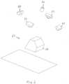
- the identification system 18includes a depth detection system 60 and a plurality of perception units 62 that are generally directed toward the sloped surface 16. As discussed in more detail below with reference to Figure 8 , when the identification system 18 senses any motion, the system will scan the area of the sloped surface 16 as shown in Figure 3 . The identification system 18 may detect motion using a beam brake sensor near the bottom of the sloped surface, or may be provided by the depth detection system 60. Once triggered, the depth detection system 60 will conduct a 3D depth scan of the area, which presumably includes one object 64 and may include more than one object 66 (for example, if the cleated conveyor brought two objects up in one cleated section, or if the worker replaced an object back on the sloped surface 16).
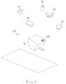
- the systemwill then continue to scan die field until it detects an object has been lifted from the sloped surface 16 and is being moved closer to the detection system 60 as shown in Figure 4 .
- the significance of thisis that the system will thereby isolate an object that a human worker has lifted and thereby selected for processing.
- the systemwill concentrate on the area of the object identified as being lifted, and thereby exclude other areas of the field of view as shown diagrammatically Figure 5 .
- the object 64is identified as being lifted, and the system will exclude other areas of view, which includes another object 66 even though an indicia label is visible on the object 66 while none is yet visible on the object 64.
- the systemwill then maintain a view of this perception area 63 of the object 64 as shown in Figure 6 until identifying indicia is perceived or the object 64 is removed from view.
- the human workermay rotate the item as shown in Figure 7 until identifying indicia 68 is detected by the perception units 62. In this way, a human worker may lift an object and rotate the object if needed until the system detects identifying indicia.
- the feedback system 20can prompt the worker to move the object to an identified processing location.
- the feedback system 20can provide other information to the worked, such as an indication that the system has isolated a lifted object and is searching for an identifying indicia, a status indicator showing that more than one object is present in the presentation area 16, or an indication that the lifted object has been removed from the presentation area 16. These indications can be through a color changing light, a series of lights aligned with respective text, a display screen, a projection on the presentation area, auditory cues, or a combination thereof. While the feedback system 20 is shown in Figure 1 to be to the side of the worker, one or more portions or functionalities of the feedback system 20 may be located adjacent to the identification system 18.
- An important aspect of certain embodiments of the present inventionis the ability to identify via barcode or other visual markings of objects by employing a perception system that may quickly scan the object as held by a human worker. Automated scanning systems would be unable to see barcodes on objects that are presented in a way that their barcodes are not exposed or visible without rotation. The system therefore is designed to view an object from a large number of different views very quickly, reducing or eliminating the possibility of the system not being able to view identifying indicia on an object.
- key features in the perception systemare the specific design of the perception system so as to maximize the probability of a successful scan, while simultaneously minimizing the average scan time.
- the probability of a successful scan and the average scan timemake up key performance characteristics.
- These key performance characteristicsare determined by the configuration and properties of the perception system, as well as the object set and how they are marked.
- the key performance characteristicsmay be optimized for a given item set and method of labeling. Parameters of the optimization for a system include how many scanners, where and in what orientation to place them, and what sensor resolutions and fields of view for the scanners to use. Optimization can be done through trial and error, or by simulation with models of the object.
- a scanner performance modelprovides the range of positions, orientations and barcode element size that an identifying symbol can be detected and decoded by the scanner, where the barcode element size is the size of the smallest feature on the symbol. These are typically rated at a minimum and maximum range, a maximum skew angle, a maximum pitch angle, and a minimum and maximum tilt angle.
- Performance requirements for such camera-based scannersare that they are able to detect symbols within some range of distances as long as both pitch and skew of the plane of the symbol are within the range of plus or minus 45 degrees, while the tilt of the symbol can be arbitrary (between 0 and 360 degrees).
- the scanner performance modelpredicts whether a given symbol in a given position and orientation will be detected.
- the scanner performance modelis coupled with a model of where symbols would expect to be positioned and oriented.
- a symbol pose modelis the range of all positions and orientations, in other words poses, in which a symbol will expect to be found.
- the symbol pose modelis itself a combination of an article gripping model, which predicts how objects will be held by the robotic system, as well as a symbol-item appearance model, which describes the possible placements of the symbol on the object.
- the symbol pose modelis itself a combination of the symbol-item appearance model, as well as an inbound-object pose model, which models the distribution of poses over which inbound articles are presented to the scanner.
- These modelsmay be constructed empirically, modeled using an analytical model, or approximate models may be employed using simple sphere models for objects and a uniform distributions over the sphere as a symbol-item appearance model.
- the detection processbegins (step 70) and the system uses the identification system 18 to determine whether any motion is detected (step 72), e.g., by noting any change in consecutively obtained data.
- the systemwill detect objects in the presentation area 16 (step 74), e.g., by using edge detection techniques, volumetric or topographical scans, etc. This step allows the system to isolate and track individual objects, as well as identifying and discarding non-object motion data, such as operator movements.
- the identification system 18can, at this point, attempt engage the perception units 62 to capture identifying indicia on detected objects and gather information from the system or indicia associated with the identified objects.
- the depth detection system 60continues to monitor the presentation area 16 to determine whether any object is moving from a surface of the presentation area 16 toward the detection system 60, and if so, to isolate that object for further processing (step 76). Once an object is determined to be moving toward the detection system 60, for example because a person is lifting the object, the system will determine whether the object has been identified, and if not, will continue to engage the perception units 62 to try to capture any identifying indicia on the object (step 80).
- the feedback system 20indicates the status of the pick to the worker through audio or visual cues. For example, distinct cues can be provided for when motion is detected, when one object has been detected, when multiple objects are detected, when the identity of an object is detected (which can indicate which object is identified, for example, by projecting a light onto the object, or using speech to identify the object), when an object is lifted, and where to route a lifted object if it has been identified. If any identifying indicia is found, the system will indicate that the object has been identified (step 81), indicate a routing location for the object by, for example, illuminating a pair of wing location lights and prompting the human worker to move the object to the carriage of the associated wing location (step 82).
- the systemconfirms that the object has been placed in the routing location, for example, with beam breaks or force sensors on the carriage (step 83). Once the object is confirmed to be at the routing location, the feedback system is reset (step 86), and the process can end (step 88). If, after a predetermined amount of time, the object is not confirmed to be at the routing location, the feedback system 20 can indicate an error, and the process will halt until the worker resolves the error, either by placing the object in the routing location or otherwise updating the system with the status of the object (e.g. damaged, sent to manual sortation, reintroduced to input area, lost, etc.).
- the feedback systemcan indicate an error, and the process will halt until the worker resolves the error, either by placing the object in the routing location or otherwise updating the system with the status of the object (e.g. damaged, sent to manual sortation, reintroduced to input area, lost, etc.).
- the feedback systemcan also instruct or otherwise indicate to a worker that the object has not yet been identified (step 84), and other areas of the object need to be presented to the perception units 62, such as by turning the object or flattening the indicia, order to capture the identifying indicia.
- the systemwill maintain a view of the general area of the object to permit this rotation.
- the processcontinues to loop until either the object is removed from the view (step 85), or any identifying indicia is found and the process continues to step 81. If the object is removed from view (for example, if placed in a manual sortation location, or in some embodiments, if placed back onto the surface of the presentation area 16), the feedback system will be reset, and the process will end.
- the infeed conveyorcan advance and provide the presentation area with another object, and the process can begin again.
- a main routing locationmay not be available at a given time, and the process could indicate to the worker to place the object at a holding location until a main routing location becomes available.
- a main routing locationcan become available after the process of Figure 8 ends if, for example, the last object placed at its routing location fulfills an order, and is removed for further processing, allowing a location to be available for another object.
- the feedback system 20can inform the worker that an object in the holding area before providing another object to the presentation area 16.
- carriagee.g., 28, 38, 48
- carriagemay include beam break sensors 92, 94 as shown Figure 9
- a force torque sensor 96for detecting a weight of an object in the carriage, to determine both when an object is received by the carriage and to confirm that an object has been dumped by the carriage into a destination bin.
- a force torque sensormay be positioned between a support structure and the carriage such that the force torque sensor bears the weight of the carriage.
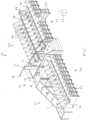
- Figure 9shows a shuttle wing section 36 that includes the carriage 48 bearing an object 90.
- the carriage 48is adapted to move along track 50 until it reaches a selected destination location 46, and as shown in Figure 11 , the carriage is adapted to then rotate to dump the object into the destination location.
- the beam break sensors and/or the weight sensormay confirm that the object has been transferred to the destination location.
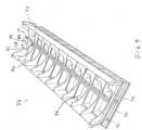
- Figures 12 - 18show a shuttle wing processing section 36' for use in a system in accordance with a further embodiment of the present invention that includes infeed conveyors 98 and output conveyors 100.
- Figure 12shows a shuttle carriage 48' that includes beam break sensors 92, 94 and/or weight sensors 96.
- the shuttle carriage 48'moves along track 50' between destination locations 46' (as shown in Figure 13 ), and may be actuated to dump the object 94 into a selected destination location (as shown in Figure 14 ).
- the destination locations 46'are provided on infeed conveyors 98 that may be biased (e.g., gravity biased) to urge the destination locations toward one end 58 of the shuttle wing processing section 36'.
- FIGS 15A and 15Bwhen a destination bin 46' is selected for removal (e.g., because the bin is full or otherwise ready for further processing), the system will urge the completed bin onto an output conveyor 100 to be brought to a further processing or shipment station.
- the conveyor 100may be biased (e.g., by gravity or power) to cause any bin on the conveyor to be brought to an output location as shown in Figures 17 and 18 .
- Figures 15A and 15Bshow a bin being urged from the plurality of destination bins, onto the output conveyor 100 by the use of a displacement mechanism 102. In accordance with further embodiments, other displacement mechanisms may be used.
- the destination binsmay be provided as boxes or containers or any other type of device that may receive and hold an item.
- the destination binsmay be provided in a box tray including inner sides for receiving a box, and a kicker plate that is engageable with a box kicker.
- a box kicker 584may be suspended by and travel along a track 586, and may include a rotatable arm 588 and a roller wheel 590 at the end of the arm 588.
- the arm 588continues to rotate, urging the box tray assembly 580 from a first conveyor 582 to a second conveyor 580.
- the roller wheel 590is designed to contact the kicker plate 551 of a box tray assembly 581 to push the box tray assembly 581 onto the conveyor 580.
- a systemmay be used to provide that boxes that are empty or finished being unloaded may be removed (e.g., from conveyor 582), or that boxes that are full or finished being loaded may be removed (e.g., from conveyor 582).
- the conveyors 580, 582may also be coplanar, and the system may further include transition roller 583 to facilitate movement of the box tray assembly 581, e.g., by being activated to pull the box tray over to the conveyor 580.
- each of the destination binsmay be urged together, and the system will record the change in position of any of the bins that moved. This way, a new empty bin may be added to the end, and the system will record the correct location and identified processing particulars of each of the destination bins.
- Figure 19shows a sortation process of the invention.
- a sorting stationreceives a new object (step 202).
- the systemidentifies the new object (step 204) with the object identification system 18.
- the systemdetermines whether any routing location has yet been assigned to the new object (step 206). If so, the system routes the object to that location (step 218). If not, the system then determines whether a next location is available (Step 208).
- step 208the system the assigns a next location to the object (step 216), and the object is then placed in that location (step 218).
- the number of objects at the locationis then updated (step 220), and if the location is then full (step 222), the system identifies that the location is ready for further processing (step 226).
- the further processingmay, for example, include collecting the objects at the location for transport to a shipping location. If the location is not full, the system then determines, based on prior knowledge and/or heuristics, whether the location is unlikely to receive a further object (step 224). If it is not likely to receive a further object, the system identifies that the location is ready for further processing (step 226). If it is likely to receive a further object, the system returns to receiving a new object (step 202).
- step 208the system may (either with or without input from a human) determine whether to retry identifying the object (step 210). If so, then the system would return the object to the input stream (step 212) to be again received at a later time (step 202). If it is determined that the object would not be reintroduced to the input stream for identification, the system would place the object in a manual sorting area for sortation by a human (step 214), and the process would continue with a new object.
- Figure 20shows a system 300 that is not a part of the invention that includes an infeed area 310 into which objects may be provided.
- the objectsmay be provided as a generally singulated stream of objects by a programmable motion device, or by having an inclined cleated conveyor draw a stream of objects up from a hopper into which objects may have been deposited, e.g., by a dumper or transferred from a Gaylord.
- An infeed conveyor 312conveys objects through the infeed area 310 to a processing station 314 that includes a presentation area such as a declining sloped surface 316.
- the infeed conveyormay include cleats for assisting in lifting the objects from the infeed conveyor to the sloped surface 316.
- the systemalso includes an identification system 318 that includes a depth detection system and a perception system as discussed above with reference to Figures 2 - 7 .
- an identification system 318that includes a depth detection system and a perception system as discussed above with reference to Figures 2 - 7 .
- a human worker in a workstation 321lifts an object from the sloped surface 316, and once the object is identified (as optionally indicated by feedback system 328), a pair of lights (e.g., pair 320, pair 322, pair 324 or pair 326) is illuminated.
- Each pair of lights 320, 322, 324, 326is associated with a shuttle wing section 330, 332, 334, 336 that includes a shuttle carriage 340, 342, 344, 346 that rides on a track 350, 352, 354, 356 between rows of destination bins 360, 362, 364, 366 that may be provided on carts 368 as discussed above.
- each cartmay support two destination bins as shown.
- the identification system 318includes a depth detection system and a plurality of perception units as discussed above that are generally directed toward the sloped surface 316. As discussed above with reference to Figure 8 , when the depth detection system senses any motion, the system will scan the area of the sloped surface 316. The motion may be detected by a beam brake sensor near the bottom of the sloped surface, or may be provided by the depth detection system itself. Once triggered, the depth detection system will conduct a 3D depth scan of the area, which presumably includes one object and may include more than one object (for example, if the cleated conveyor brought two objects up in one cleated section).
- the systemwill then continue to scan the field until it detects an object being moved closer to the detection system.
- the significance of thisis that the system will thereby singulate an object that a human worker has lifted and thereby selected for processing.
- the systemwill concentrate on the area of the object identified as being lifted, and thereby exclude other areas of the field of view as shown discussed above.
- the objectis identified as being lifted, and the system will exclude other areas of view, which includes another object even though an indicia label is visible on the object while none is yet visible on the object as discussed above.
- the systemwill then maintain a view of the general area of the object until identifying indicia is perceived or the object is removed from view.
- the human workermay rotate the item as shown discussed above until identifying indicia is detected by the perception units. In this way, a human worker may lift an object and rotate the object if needed until the system detects identifying indicia, and an optional light may be illuminated or change color (e.g., to green) or a display device 328 may provide information to indicate that the object is identified.
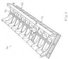
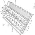
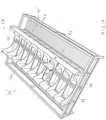
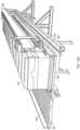
- Figures 21 - 24show a semi-autonomous processing system according to the present invention that includes an infeed area 410 into which objects may be provided.
- the objectsmay be provided as a generally singulated stream of objects by a programmable motion device, or by having an inclined cleated conveyor draw a stream of objects up from a hopper into which objects may have been deposited, e.g., by a dumper or transferred from a Gaylord.
- An infeed conveyor 412conveys objects through the infeed area 410 to a processing station 414 that includes a presentation area 416.
- the systemalso includes an identification system 418 that includes a depth detection system and a perception system as discussed above with reference to Figures 2 - 7 .
- an identification system 418that includes a depth detection system and a perception system as discussed above with reference to Figures 2 - 7 .
- a human worker in a workstation area 451lifts an object from the presentation area 416, and once the object is identified (as optionally indicated by a light or monitor as discussed above), a pair of lights (e.g., pair 420, pair 422, pair 424 or pair 426) is illuminated.
- Each pair of lights 420, 422, 424, 426is associated with a shuttle wing section 430, 432, 434, 436 that includes a shuttle carriage 440, 442, 444, 446 that rides on a track 450, 452, 454, 456 between rows of destination bins 460, 462, 464, 466 that may be provided on carts 468 as discussed above.
- each cartmay support two destination bins as shown.
- the systemthen detects this placement, and moves the shuttle carriage to be adjacent a desired destination bin, and tilts the carriage to drop the object in the bin as discussed above with reference to Figures 9 - 19 .
- Operation of the systemmay be governed by a processing system 458 that includes one or more computer processing systems.
- the identification system 418includes a depth detection system and a plurality of perception units as discussed above that are generally directed toward the presentation area 416. As discussed above with reference to Figure 8 , when the depth detection system senses any motion, the system will scan the area of the presentation area 416. The motion may be detected by the depth detection system itself. Once triggered, the depth detection system will conduct a 3D depth scan of the area, which presumably includes one object and may include more than one object.
- the systemwill then continue to scan the field until it detects an object being moved closer to the detection system. Again, the significance of this is that the system will thereby singulate an object that a human worker has lifted and thereby selected for processing. At this time, the system will concentrate on the area of the object identified as being lifted, and thereby exclude other areas of the field of view as shown discussed above. In particular, the object is identified as being lifted, and the system will exclude other areas of view, which includes another object even though an indicia label is visible on the object while none is yet visible on the object as discussed above.
- the systemwill then maintain a view of the general area of the object until identifying indicia is perceived or the object is removed from view.
- the human workermay rotate the item as shown discussed above until identifying indicia is detected by the perception units. In this way, a human worker may lift an object and rotate the object if needed until the system detects identifying indicia, and an optional light may be illuminated or change color (e.g., to green) or a display device 428 may provide information to indicate that the object is identified.
- the human workeris provided with an activated chair 448 that can be actively moved to turn toward the designated chute 421, 423, 425, 427 responsive to the identification of the object and the associated shuttle wing section such that once identified, the chair is actively turned to face the chute into which the object is to be placed.
- the flexible correspondence between sorter outputs and destinationsprovides that there may be fewer sorter outputs than destinations, so the entire system may require less space.
- the flexible correspondence between sorter outputs and destinationsalso provides that the system may choose the most efficient order in which to handle objects, in a way that varies with the particular mix of objects and downstream demand.
- the systemis also easily scalable, by adding shuttle wings and destination stations, and more robust since the failure (or off-line status) of a single destination location might be handled dynamically without even stopping the system. It should be possible for sorters to exercise discretion in the order of objects, favoring objects that need to be handled quickly.
- Systems of the inventionare highly scalable in terms of sorts-per-hour as well as the number of storage bins and destination bins that may be available.
- the systemprovides in a specific embodiment an input system that interfaces to the customer's conveyors and containers, stores objects for feeding into the system, and feeds those objects into the system at a moderate and controllable rate.
- the interface to the customer's processtakes the form of a dumper from a Gaylord, but many other embodiments are possible.
- feeding into the systemis by an inclined cleated conveyor with overhead flow restrictors, e.g., baffles.
- the systemfeeds objects in at a modest controlled rate.
- Many optionsare available, including variations in the conveyor slope and speed, the presence, size and structure of cleats and baffles, and the use of sensors to monitor and control the feed rate.
- the systemincludes in a specific embodiment a primary perception system that monitors the stream of objects on the primary conveyor.
- the primary perception systemmay identify the object to speed or simplify subsequent operations. For example, knowledge of the objects on the primary conveyor may enable the system to make better choices regarding which objects to move to provide a singulated stream of objects.
- the flexible correspondence between sorter outputs and destinationsprovides that there may be fewer sorter outputs than destinations, so the entire system may require less space.
- the flexible correspondence between sorter outputs and destinationsalso provides that the system may choose the most efficient order in which to handle objects, in a way that varies with the particular mix of objects and downstream demand.
- the systemis also easily scalable, by adding sorters, and more robust since the failure of a single sorter might be handled dynamically without even stopping the system. It should be possible for sorters to exercise discretion in the order of objects, favoring objects that need to be handled quickly, or favoring objects for which the given sorter may have a specialized gripper.
- the operations of the systems described hereinare coordinated by the central control system 52, 358 and 458 as shown in Figures 1 , 20 and 21 .
- the central control systemis comprised of one or more workstations or central processing units (CPUs).
- CPUscentral processing units
- the correspondence between barcodes, for example, and outbound destinationsis maintained by the central control system in a database called a manifest.
- the central control systemmaintains the manifest by communicating with a warehouse management system (WMS). If the perception system successfully recognizes a marking on the object, then the object is then identified and forwarded to an assigned destination station. If the object is not identified, the robotic system may divert the object to a human sortation bin to be reviewed by a human.
- WMSwarehouse management system
Landscapes
- Engineering & Computer Science (AREA)
- Mechanical Engineering (AREA)
- General Engineering & Computer Science (AREA)
- Control Of Conveyors (AREA)
Description
- The present application claims priority to
U.S. Provisional Patent Application Ser. No. 62/752,607 filed October 30, 2018 - The invention generally relates to automated, robotic and other processing systems, and relates in particular to automated and robotic systems intended for use in environments requiring, for example, that a variety of objects (e.g., articles, parcels or packages) be processed, e.g., sorted and/or otherwise distributed to several output destinations.
- Many object distribution systems receive objects in an organized or disorganized stream that may be provided as individual objects or objects aggregated in groups such as in bags, arriving on any of several different conveyances, commonly a conveyor, a truck, a pallet, a Gaylord, or a bin. Each object must then be distributed to the correct destination container, as determined by identification information associated with the object, which is commonly determined by a label printed on the object. The destination container may take many forms, such as a bag or a bin.
- The processing of such objects has traditionally been done by human workers that scan the objects, e.g., with a hand-held barcode scanner, and then place the objects at assigned locations. For example many order fulfillment operations achieve high efficiency by employing a process called wave picking. In wave picking, orders are picked from warehouse shelves and placed at locations (e.g., into bins) containing multiple orders that are sorted downstream. At the processing stage individual objects are identified, and multi-object orders are consolidated, for example into a single bin or shelf location, so that they may be packed and then shipped to customers. The processing (e.g., sorting) of these objects has traditionally been done by hand. A human sorter picks an object from an incoming bin, finds a barcode on the object, scans the barcode with a handheld barcode scanner, determines from the scanned barcode the appropriate bin or shelf location for the article, and then places the article in the so-determined bin or shelf location where all objects for that order have been defined to belong. Automated systems for order fulfillment have also been proposed. See for example,
U.S. Patent Application Publication No. 2014/0244026 , which discloses the use of a robotic arm together with an arcuate structure that is movable to within reach of the robotic arm. - In conventional parcel sortation systems, human workers or automated systems typically retrieve objects in an arrival order, and sort each object into a collection bin based on a set of given heuristics. For instance, all objects of like type might go to a collection bin, or all objects in a single customer order, or all objects destined for the same shipping destination, etc. The human workers or automated systems are required to receive objects and to move each to their assigned collection bin. If the number of different types of input (received) objects is large, a large number of collection bins is required.
- Such a system has inherent inefficiencies as well as inflexibilities since the desired goal is to match incoming objects to assigned collection bins. Such systems may require a large number of collection bins (and therefore a large amount of physical space, large capital costs, and large operating costs) in part, because sorting all objects to all destinations at once is not always most efficient.
- Certain partially automated sortation systems involve the use of recirculating conveyors and tilt trays, where the tilt trays receive objects by human sortation (human induction), and each tilt tray moves past a scanner. Each object is then scanned and moved to a pre-defined location assigned to the object. The tray then tilts to drop the object into the location. Further, partially automated systems, such as the bomb-bay style recirculating conveyor, involve having trays open doors on the bottom of each tray at the time that the tray is positioned over a predefined chute, and the object is then dropped from the tray into the chute. Again, die objects are scanned while in the tray, which assumes that any identifying code is visible to the scanner.
- Such partially automated systems are lacking in key areas. As noted, these conveyors have discrete trays that can be loaded with an object; they then pass through scan tunnels that scan the object and associate it with the tray in which it is riding. When the tray passes the correct bin, a trigger mechanism causes the tray to dump the object into the bin. A drawback with such systems however, is that every divert requires an actuator, which increases the mechanical complexity and the cost per divert can be very high.
- An alternative is to use human labor to increase the number of diverts, or collection bins, available in the system. This decreases system installation costs, but increases the operating costs. Multiple cells may then work in parallel, effectively multiplying throughput linearly while keeping the number of expensive automated diverts at a minimum. Such diverts do not ID an object and cannot divert it to a particular spot, but rather they work with beam breaks or other sensors to seek to ensure that indiscriminate bunches of objects get appropriately diverted. The lower cost of such diverts coupled with the low number of diverts keep the overall system divert cost low.
- Unfortunately, these systems don't address the limitations to total number of system bins. The system is simply diverting an equal share of the total objects to each parallel manual ceil. Thus each parallel sortation cell must have all the same collection bins designations; otherwise an object might be delivered to a cell that does not have a bin to which that object is mapped. There remains a need for a more efficient and more cost effective object sortation system that sorts objects of a variety of sizes and weights into appropriate collection bins or trays of fixed sizes, yet is efficient in handling objects of such varying sizes and weights.
US2004/195320 A1 discloses a system for projecting a display onto an item, using an acquisition device to capture indicia on each parcel, a tracking system, a controller or computer to select the display based on the indicia, and one or more display projectors. The display includes or connotes a handling instruction. The system includes a laser projection system to paint the selected display directly onto a selected exterior surface of the corresponding parcel, for multiple parcels simultaneously. The system may be configured to move each display in order follow each moving parcel so that each display remains legible to a viewer in a display zone where handling takes place.- Said document discloses a semi-autonomous processing system for processing objects comprising a processing station; an input conveyance system for moving objects to the processing station that includes a presentation; an identification system including perception units that are directed toward the presentation area for providing perception data regarding an object in the presentation area; at least two transport systems, each of which is adapted to receive the object and move the object in either of reciprocal directions; and a manual workstation area between the perception area and the at least two transport systems.
- In accordance with an embodiment, the invention provides a semi-autonomous processing system for processing objects. The semi-autonomous processing system includes an input conveyance system for moving objects to a presentation area, a perception system including perception units that are directed toward a detection area for providing perception data regarding an object in the presentation area, at least two transport systems, each of which is adapted to receive the object and move the object in either of reciprocal directions, and a manual workstation area between the perception area the at least two transport systems.
- The invention is defined by the independent claims. Embodiments of the invention become apparent form the dependent claims.
- The following description may be further understood with reference to the accompanying drawings in which:
Figure 1 shows an illustrative diagrammatic view of a semi-autonomous processing system that is not a part of the present invention;Figure 2 shows an illustrative diagrammatic view of an identification system ofFigure 1 ;Figure 3 shows an illustrative diagrammatic view of the identification system ofFigure 2 with the depth detection system engaged;Figure 4 shows an illustrative diagrammatic view of the system ofFigure 3 with an object being moved closer to the detection system;Figure 5 shows an illustrative diagrammatic view of the system ofFigure 4 with non-object areas of the field of view being excluded;Figure 6 shows an illustrative diagrammatic view of the system ofFigure 5 with the view of the object being maintained;Figure 7 shows an illustrative diagrammatic view of the system ofFigure 6 with the object having been rotated;Figure 8 shows an illustrative diagrammatic flowchart of the detection processing in accordance with an embodiment of the invention;Figure 9 shows an illustrative diagrammatic view of a shuttle wing section for use in a semi-autonomous processing system in accordance with an embodiment of the present invention;Figure 10 shows an illustrative diagrammatic view of the shuttle wing section ofFigure 9 with the carriage moved along its track;Figure 11 shows an illustrative diagrammatic view of the shuttle wing section ofFigure 10 with the carriage dropping an object into a destination location;Figure 12 shows an illustrative diagrammatic view of a shuttle wing section for use in a semi-autonomous processing system in accordance with another embodiment of the present invention;Figure 13 shows an illustrative diagrammatic view of the shuttle wing section ofFigure 12 with the carriage moved along its track;Figure 14 shows an illustrative diagrammatic view of the shuttle wing section ofFigure 13 with the carriage dropping an object into a destination location;Figures 15A and 15B show an illustrative diagrammatic views of a bin removal system in accordance with an embodiment of the invention with a bin selected for removal (Figure 15A ) and being removed (Figure 15B );Figures 16A - 16D show illustrative diagrammatic views of a further embodiment of a bin displacement system for use in further embodiments of the invention;Figure 17 shows an illustrative diagrammatic view of a bin being displaced onto an output conveyor in accordance with an embodiment of the present invention;Figure 18 shows an illustrative diagrammatic view of the bin and output conveyor ofFigure 17 with the bin moved along the output conveyor;Figure 19 shows an illustrative diagrammatic flowchart of a sortation process in accordance with an embodiment of the present invention;Figure 20 shows an illustrative diagrammatic view of a semi-autonomous processing system that is not a part of the present invention that includes an additional shuttle wing section that is orthogonally disposed with regard to other shuttle wing sections;Figure 21 shows an illustrative diagrammatic view of a semi-autonomous processing system according to the present invention that includes an infeed area and a processing station including an activated chair;Figure 22 shows an illustrative diagrammatic view of the infeed area of the system ofFigure 21 ;Figure 23 shows an illustrative diagrammatic view of the processing station ofFigure 21 including the activated chair; andFigure 24 shows an illustrative diagrammatic view of the processing station ofFigure 21 with the activated chair having been moved.- The drawings are shown for illustrative purposes only.
- Processing objects in a distribution center (e.g., sorting) is one application for automatically identifying and moving objects. In a shipping distribution center for example, objects commonly arrive in trucks, are conveyed to sortation stations where they are processed, e.g., sorted, according to desired destinations, aggregated in bags, and then loaded in trucks for transport to the desired destinations. Another application may be in the shipping department of a retail store or order fulfillment center, which may require that objects be processed for transport to different shippers, or to different distribution centers of a particular shipper. In a shipping or distribution center the objects may take form of plastic bags, boxes, tubes, envelopes, or any other suitable container, and in some cases may also include objects not in a container. In a shipping or distribution center the desired destination is commonly obtained by reading identifying information printed on the object or on an attached label. In this scenario the destination corresponding to identifying information is commonly obtained by querying the customer's information system. In other scenarios the destination may be written directly on the object, or may be known through other means.
- Applicants have discovered that when automating sortation of objects, there are a few main things to consider: 1) the overall system throughput (objects sorted per hour), 2) the number of diverts (i.e., number of discrete locations to which an object can be routed), 3) the total area of the sortation system (square feet), and 4) the annual costs to run the system (man-hours, electrical costs, cost of disposable components).
- The invention provides a method according to claim 11.
- Important components of a semi-automated object identification and processing system include an input conveyance system, a perception system, a primary transport system, and secondary transport systems.
Figure 1 for example, shows asystem 10, which is not a part of the present invention, that includes aninfeed area 12 into which objects may be provided The objects may be provided as a generally singulated stream of objects by a programmable motion device, or by having an inclined cleated conveyor draw a stream of objects up from a hopper into which objects may have been deposited, e.g., by a dumper or transferred from a Gaylord. An infeed conveyor 11 conveys objects through theinfeed area 12 to aprocessing station 14 that includes a presentation area such as a declining slopedsurface 16. The infeed conveyor may include cleats for assisting in lifting the objects from the infeed conveyor to the slopedsurface 16. - The system also includes an
identification system 18 that includes a depth detection system and a perception system as discussed in more detail below. Generally, a human worker aworkstation area 21 lifts an object from the slopedsurface 16, and once the object is identified (as optionally indicated by afeedback device 20 such as a light or a speaker), a pair of lights (e.g.,pair 22,pair 24 or pair 26) is illuminated to show the worker where to place the object. Each pair oflights shuttle wing shuttle carriage track destination bins carts 54. For example, each cart may support two destination bins as shown. Once a pair of lights (22, 24, 26) is illuminated, the human worker places the object in the associated carriage. The system then detects this placement, and moves the shuttle carriage to be adjacent a desired destination bin, and tilts the carriage to drop the object in the bin as discussed in more detail below. Operation of the system may be governed by aprocessing system 52 that includes one or more computer processing systems. - With reference to
Figure 2 , theidentification system 18 includes adepth detection system 60 and a plurality ofperception units 62 that are generally directed toward the slopedsurface 16. As discussed in more detail below with reference toFigure 8 , when theidentification system 18 senses any motion, the system will scan the area of the slopedsurface 16 as shown inFigure 3 . Theidentification system 18 may detect motion using a beam brake sensor near the bottom of the sloped surface, or may be provided by thedepth detection system 60. Once triggered, thedepth detection system 60 will conduct a 3D depth scan of the area, which presumably includes oneobject 64 and may include more than one object 66 (for example, if the cleated conveyor brought two objects up in one cleated section, or if the worker replaced an object back on the sloped surface 16). - The system will then continue to scan die field until it detects an object has been lifted from the sloped
surface 16 and is being moved closer to thedetection system 60 as shown inFigure 4 . The significance of this is that the system will thereby isolate an object that a human worker has lifted and thereby selected for processing. At this time, the system will concentrate on the area of the object identified as being lifted, and thereby exclude other areas of the field of view as shown diagrammaticallyFigure 5 . In particular, theobject 64 is identified as being lifted, and the system will exclude other areas of view, which includes anotherobject 66 even though an indicia label is visible on theobject 66 while none is yet visible on theobject 64. - Once the area of the
object 64 is identified, the system will then maintain a view of thisperception area 63 of theobject 64 as shown inFigure 6 until identifying indicia is perceived or theobject 64 is removed from view. In particular, if identifying indicia is not facing theperception units 62, the human worker may rotate the item as shown inFigure 7 until identifyingindicia 68 is detected by theperception units 62. In this way, a human worker may lift an object and rotate the object if needed until the system detects identifying indicia. Once the system identifying indicia is detected, thefeedback system 20 can prompt the worker to move the object to an identified processing location. - In addition to indicating when an identifying indicia is detected, the
feedback system 20 can provide other information to the worked, such as an indication that the system has isolated a lifted object and is searching for an identifying indicia, a status indicator showing that more than one object is present in thepresentation area 16, or an indication that the lifted object has been removed from thepresentation area 16. These indications can be through a color changing light, a series of lights aligned with respective text, a display screen, a projection on the presentation area, auditory cues, or a combination thereof. While thefeedback system 20 is shown inFigure 1 to be to the side of the worker, one or more portions or functionalities of thefeedback system 20 may be located adjacent to theidentification system 18. - An important aspect of certain embodiments of the present invention, is the ability to identify via barcode or other visual markings of objects by employing a perception system that may quickly scan the object as held by a human worker. Automated scanning systems would be unable to see barcodes on objects that are presented in a way that their barcodes are not exposed or visible without rotation. The system therefore is designed to view an object from a large number of different views very quickly, reducing or eliminating the possibility of the system not being able to view identifying indicia on an object.
- It is also proposed that key features in the perception system are the specific design of the perception system so as to maximize the probability of a successful scan, while simultaneously minimizing the average scan time. The probability of a successful scan and the average scan time make up key performance characteristics. These key performance characteristics are determined by the configuration and properties of the perception system, as well as the object set and how they are marked. The key performance characteristics may be optimized for a given item set and method of labeling. Parameters of the optimization for a system include how many scanners, where and in what orientation to place them, and what sensor resolutions and fields of view for the scanners to use. Optimization can be done through trial and error, or by simulation with models of the object.
- Optimization through simulation may employ a scanner performance model. A scanner performance model provides the range of positions, orientations and barcode element size that an identifying symbol can be detected and decoded by the scanner, where the barcode element size is the size of the smallest feature on the symbol. These are typically rated at a minimum and maximum range, a maximum skew angle, a maximum pitch angle, and a minimum and maximum tilt angle.
- Performance requirements for such camera-based scanners are that they are able to detect symbols within some range of distances as long as both pitch and skew of the plane of the symbol are within the range of plus or minus 45 degrees, while the tilt of the symbol can be arbitrary (between 0 and 360 degrees). The scanner performance model predicts whether a given symbol in a given position and orientation will be detected.
- The scanner performance model is coupled with a model of where symbols would expect to be positioned and oriented. A symbol pose model is the range of all positions and orientations, in other words poses, in which a symbol will expect to be found. For the scanner, the symbol pose model is itself a combination of an article gripping model, which predicts how objects will be held by the robotic system, as well as a symbol-item appearance model, which describes the possible placements of the symbol on the object. For the scanner, the symbol pose model is itself a combination of the symbol-item appearance model, as well as an inbound-object pose model, which models the distribution of poses over which inbound articles are presented to the scanner. These models may be constructed empirically, modeled using an analytical model, or approximate models may be employed using simple sphere models for objects and a uniform distributions over the sphere as a symbol-item appearance model.
- With reference to
Figure 8 , the detection process in accordance with an embodiment begins (step 70) and the system uses theidentification system 18 to determine whether any motion is detected (step 72), e.g., by noting any change in consecutively obtained data. Once motion is detected, the system will detect objects in the presentation area 16 (step 74), e.g., by using edge detection techniques, volumetric or topographical scans, etc. This step allows the system to isolate and track individual objects, as well as identifying and discarding non-object motion data, such as operator movements. Theidentification system 18 can, at this point, attempt engage theperception units 62 to capture identifying indicia on detected objects and gather information from the system or indicia associated with the identified objects. Once one or more objects have been detected, thedepth detection system 60 continues to monitor thepresentation area 16 to determine whether any object is moving from a surface of thepresentation area 16 toward thedetection system 60, and if so, to isolate that object for further processing (step 76). Once an object is determined to be moving toward thedetection system 60, for example because a person is lifting the object, the system will determine whether the object has been identified, and if not, will continue to engage theperception units 62 to try to capture any identifying indicia on the object (step 80). - The
feedback system 20 indicates the status of the pick to the worker through audio or visual cues. For example, distinct cues can be provided for when motion is detected, when one object has been detected, when multiple objects are detected, when the identity of an object is detected (which can indicate which object is identified, for example, by projecting a light onto the object, or using speech to identify the object), when an object is lifted, and where to route a lifted object if it has been identified. If any identifying indicia is found, the system will indicate that the object has been identified (step 81), indicate a routing location for the object by, for example, illuminating a pair of wing location lights and prompting the human worker to move the object to the carriage of the associated wing location (step 82). In certain embodiments, the system confirms that the object has been placed in the routing location, for example, with beam breaks or force sensors on the carriage (step 83). Once the object is confirmed to be at the routing location, the feedback system is reset (step 86), and the process can end (step 88). If, after a predetermined amount of time, the object is not confirmed to be at the routing location, thefeedback system 20 can indicate an error, and the process will halt until the worker resolves the error, either by placing the object in the routing location or otherwise updating the system with the status of the object (e.g. damaged, sent to manual sortation, reintroduced to input area, lost, etc.). - The feedback system can also instruct or otherwise indicate to a worker that the object has not yet been identified (step 84), and other areas of the object need to be presented to the
perception units 62, such as by turning the object or flattening the indicia, order to capture the identifying indicia. The system will maintain a view of the general area of the object to permit this rotation. The process continues to loop until either the object is removed from the view (step 85), or any identifying indicia is found and the process continues to step 81. If the object is removed from view (for example, if placed in a manual sortation location, or in some embodiments, if placed back onto the surface of the presentation area 16), the feedback system will be reset, and the process will end. - Once the process is ended, the infeed conveyor can advance and provide the presentation area with another object, and the process can begin again. In some cases, as later discussed with reference to
Figure 19 , a main routing location may not be available at a given time, and the process could indicate to the worker to place the object at a holding location until a main routing location becomes available. A main routing location can become available after the process ofFigure 8 ends if, for example, the last object placed at its routing location fulfills an order, and is removed for further processing, allowing a location to be available for another object. Once a new routing location is available, thefeedback system 20 can inform the worker that an object in the holding area before providing another object to thepresentation area 16. - As referred to above in connection with
step 83, carriage (e.g., 28, 38, 48) may includebeam break sensors Figure 9 , and/or may optionally include aforce torque sensor 96 for detecting a weight of an object in the carriage, to determine both when an object is received by the carriage and to confirm that an object has been dumped by the carriage into a destination bin. Such a force torque sensor may be positioned between a support structure and the carriage such that the force torque sensor bears the weight of the carriage.Figure 9 shows ashuttle wing section 36 that includes thecarriage 48 bearing anobject 90. As further shown inFigure 10 , thecarriage 48 is adapted to move alongtrack 50 until it reaches a selecteddestination location 46, and as shown inFigure 11 , the carriage is adapted to then rotate to dump the object into the destination location. As noted above, the beam break sensors and/or the weight sensor may confirm that the object has been transferred to the destination location. Figures 12 - 18 show a shuttle wing processing section 36' for use in a system in accordance with a further embodiment of the present invention that includesinfeed conveyors 98 andoutput conveyors 100. In particular,Figure 12 shows a shuttle carriage 48' that includesbeam break sensors weight sensors 96. As discussed above, the shuttle carriage 48' moves along track 50' between destination locations 46' (as shown inFigure 13 ), and may be actuated to dump theobject 94 into a selected destination location (as shown inFigure 14 ). As noted above, the destination locations 46' are provided oninfeed conveyors 98 that may be biased (e.g., gravity biased) to urge the destination locations toward oneend 58 of the shuttle wing processing section 36'.- With reference to
Figures 15A and 15B , when a destination bin 46' is selected for removal (e.g., because the bin is full or otherwise ready for further processing), the system will urge the completed bin onto anoutput conveyor 100 to be brought to a further processing or shipment station. Theconveyor 100 may be biased (e.g., by gravity or power) to cause any bin on the conveyor to be brought to an output location as shown inFigures 17 and18 .Figures 15A and 15B show a bin being urged from the plurality of destination bins, onto theoutput conveyor 100 by the use of a displacement mechanism 102. In accordance with further embodiments, other displacement mechanisms may be used. The destination bins may be provided as boxes or containers or any other type of device that may receive and hold an item. - In accordance with further embodiments, the destination bins (e.g. boxes) may be provided in a box tray including inner sides for receiving a box, and a kicker plate that is engageable with a box kicker. With reference to
Figures 16A - 16D , abox kicker 584 may be suspended by and travel along atrack 586, and may include a rotatable arm 588 and aroller wheel 590 at the end of the arm 588. With reference to Figures 16B - 6D, when theroller wheel 590 contacts the kicker plate 551 of a box tray assembly 520, the arm 588 continues to rotate, urging thebox tray assembly 580 from afirst conveyor 582 to asecond conveyor 580. Again, theroller wheel 590 is designed to contact the kicker plate 551 of abox tray assembly 581 to push thebox tray assembly 581 onto theconveyor 580. Such a system may be used to provide that boxes that are empty or finished being unloaded may be removed (e.g., from conveyor 582), or that boxes that are full or finished being loaded may be removed (e.g., from conveyor 582). Theconveyors transition roller 583 to facilitate movement of thebox tray assembly 581, e.g., by being activated to pull the box tray over to theconveyor 580. - Following displacement of the bin onto the conveyor 100 (as shown in
Figures 17 and18 ), each of the destination bins may be urged together, and the system will record the change in position of any of the bins that moved. This way, a new empty bin may be added to the end, and the system will record the correct location and identified processing particulars of each of the destination bins. Figure 19 shows a sortation process of the invention. Once the process begins (step 200), a sorting station receives a new object (step 202). The system identifies the new object (step 204) with theobject identification system 18. The system then determines whether any routing location has yet been assigned to the new object (step 206). If so, the system routes the object to that location (step 218). If not, the system then determines whether a next location is available (Step 208).- If a next location is available (step 208), the system the assigns a next location to the object (step 216), and the object is then placed in that location (step 218). The number of objects at the location is then updated (step 220), and if the location is then full (step 222), the system identifies that the location is ready for further processing (step 226). The further processing may, for example, include collecting the objects at the location for transport to a shipping location. If the location is not full, the system then determines, based on prior knowledge and/or heuristics, whether the location is unlikely to receive a further object (step 224). If it is not likely to receive a further object, the system identifies that the location is ready for further processing (step 226). If it is likely to receive a further object, the system returns to receiving a new object (step 202).
- If in step 208 a next location is not available, the system may (either with or without input from a human) determine whether to retry identifying the object (step 210). If so, then the system would return the object to the input stream (step 212) to be again received at a later time (step 202). If it is determined that the object would not be reintroduced to the input stream for identification, the system would place the object in a manual sorting area for sortation by a human (step 214), and the process would continue with a new object.
Figure 20 shows a system 300 that is not a part of the invention that includes aninfeed area 310 into which objects may be provided. Again, the objects may be provided as a generally singulated stream of objects by a programmable motion device, or by having an inclined cleated conveyor draw a stream of objects up from a hopper into which objects may have been deposited, e.g., by a dumper or transferred from a Gaylord. Aninfeed conveyor 312 conveys objects through theinfeed area 310 to aprocessing station 314 that includes a presentation area such as a declining slopedsurface 316. The infeed conveyor may include cleats for assisting in lifting the objects from the infeed conveyor to the slopedsurface 316.- The system also includes an identification system 318 that includes a depth detection system and a perception system as discussed above with reference to
Figures 2 - 7 . Generally, a human worker in aworkstation 321 lifts an object from the slopedsurface 316, and once the object is identified (as optionally indicated by feedback system 328), a pair of lights (e.g., pair 320, pair 322,pair 324 or pair 326) is illuminated. Each pair oflights 320, 322, 324, 326 is associated with ashuttle wing section shuttle carriage track destination bins carts 368 as discussed above. For example, each cart may support two destination bins as shown. Once a pair of lights (320, 322, 324, 326) is illuminated, the human worker places the object in the associated carriage. The system then detects this placement, and moves the shuttle carriage to be adjacent a desired destination bin, and tilts the carriage to drop the object the bin as discussed above with reference toFigures 9 - 19 . Operation of the system may be governed by aprocessing system 358 that includes one or more computer processing systems. - The identification system 318 includes a depth detection system and a plurality of perception units as discussed above that are generally directed toward the
sloped surface 316. As discussed above with reference toFigure 8 , when the depth detection system senses any motion, the system will scan the area of the slopedsurface 316. The motion may be detected by a beam brake sensor near the bottom of the sloped surface, or may be provided by the depth detection system itself. Once triggered, the depth detection system will conduct a 3D depth scan of the area, which presumably includes one object and may include more than one object (for example, if the cleated conveyor brought two objects up in one cleated section). - The system will then continue to scan the field until it detects an object being moved closer to the detection system. The significance of this is that the system will thereby singulate an object that a human worker has lifted and thereby selected for processing. At this time, the system will concentrate on the area of the object identified as being lifted, and thereby exclude other areas of the field of view as shown discussed above. In particular, the object is identified as being lifted, and the system will exclude other areas of view, which includes another object even though an indicia label is visible on the object while none is yet visible on the object as discussed above.
- Once the area of the object is identified, the system will then maintain a view of the general area of the object until identifying indicia is perceived or the object is removed from view. In particular, if identifying indicia is not facing the perception units, the human worker may rotate the item as shown discussed above until identifying indicia is detected by the perception units. In this way, a human worker may lift an object and rotate the object if needed until the system detects identifying indicia, and an optional light may be illuminated or change color (e.g., to green) or a display device 328 may provide information to indicate that the object is identified.
Figures 21 - 24 show a semi-autonomous processing system according to the present invention that includes aninfeed area 410 into which objects may be provided. Again, the objects may be provided as a generally singulated stream of objects by a programmable motion device, or by having an inclined cleated conveyor draw a stream of objects up from a hopper into which objects may have been deposited, e.g., by a dumper or transferred from a Gaylord. Aninfeed conveyor 412 conveys objects through theinfeed area 410 to aprocessing station 414 that includes apresentation area 416.- With further reference to
Figure 22 , the system also includes anidentification system 418 that includes a depth detection system and a perception system as discussed above with reference toFigures 2 - 7 . Generally, a human worker in aworkstation area 451 lifts an object from thepresentation area 416, and once the object is identified (as optionally indicated by a light or monitor as discussed above), a pair of lights (e.g.,pair 420,pair 422,pair 424 or pair 426) is illuminated. Each pair oflights shuttle wing section shuttle carriage track destination bins carts 468 as discussed above. For example, each cart may support two destination bins as shown. Once a pair of lights (420, 422, 424, 426 is illuminated, the human worker places the object on achute carriages Figures 9 - 19 . Operation of the system may be governed by aprocessing system 458 that includes one or more computer processing systems. - The
identification system 418 includes a depth detection system and a plurality of perception units as discussed above that are generally directed toward thepresentation area 416. As discussed above with reference toFigure 8 , when the depth detection system senses any motion, the system will scan the area of thepresentation area 416. The motion may be detected by the depth detection system itself. Once triggered, the depth detection system will conduct a 3D depth scan of the area, which presumably includes one object and may include more than one object. - The system will then continue to scan the field until it detects an object being moved closer to the detection system. Again, the significance of this is that the system will thereby singulate an object that a human worker has lifted and thereby selected for processing. At this time, the system will concentrate on the area of the object identified as being lifted, and thereby exclude other areas of the field of view as shown discussed above. In particular, the object is identified as being lifted, and the system will exclude other areas of view, which includes another object even though an indicia label is visible on the object while none is yet visible on the object as discussed above.
- Once the area of the object is identified, the system will then maintain a view of the general area of the object until identifying indicia is perceived or the object is removed from view. In particular, if identifying indicia is not facing the perception units, the human worker may rotate the item as shown discussed above until identifying indicia is detected by the perception units. In this way, a human worker may lift an object and rotate the object if needed until the system detects identifying indicia, and an optional light may be illuminated or change color (e.g., to green) or a display device 428 may provide information to indicate that the object is identified. According to the invention, as seen in
Figures 23 and24 , the human worker is provided with an activated chair 448 that can be actively moved to turn toward the designatedchute - Systems of various embodiments provide numerous advantages because of the inherent dynamic flexibility. The flexible correspondence between sorter outputs and destinations provides that there may be fewer sorter outputs than destinations, so the entire system may require less space. The flexible correspondence between sorter outputs and destinations also provides that the system may choose the most efficient order in which to handle objects, in a way that varies with the particular mix of objects and downstream demand. The system is also easily scalable, by adding shuttle wings and destination stations, and more robust since the failure (or off-line status) of a single destination location might be handled dynamically without even stopping the system. It should be possible for sorters to exercise discretion in the order of objects, favoring objects that need to be handled quickly.
- Systems of the invention are highly scalable in terms of sorts-per-hour as well as the number of storage bins and destination bins that may be available. The system provides in a specific embodiment an input system that interfaces to the customer's conveyors and containers, stores objects for feeding into the system, and feeds those objects into the system at a moderate and controllable rate. In one embodiment, the interface to the customer's process takes the form of a dumper from a Gaylord, but many other embodiments are possible. In one embodiment, feeding into the system is by an inclined cleated conveyor with overhead flow restrictors, e.g., baffles. In accordance with certain embodiments, the system feeds objects in at a modest controlled rate. Many options are available, including variations in the conveyor slope and speed, the presence, size and structure of cleats and baffles, and the use of sensors to monitor and control the feed rate.
- The system includes in a specific embodiment a primary perception system that monitors the stream of objects on the primary conveyor. Where possible the primary perception system may identify the object to speed or simplify subsequent operations. For example, knowledge of the objects on the primary conveyor may enable the system to make better choices regarding which objects to move to provide a singulated stream of objects.
- Systems of various embodiments provide numerous advantages because of the inherent dynamic flexibility. The flexible correspondence between sorter outputs and destinations provides that there may be fewer sorter outputs than destinations, so the entire system may require less space. The flexible correspondence between sorter outputs and destinations also provides that the system may choose the most efficient order in which to handle objects, in a way that varies with the particular mix of objects and downstream demand. The system is also easily scalable, by adding sorters, and more robust since the failure of a single sorter might be handled dynamically without even stopping the system. It should be possible for sorters to exercise discretion in the order of objects, favoring objects that need to be handled quickly, or favoring objects for which the given sorter may have a specialized gripper.
- The operations of the systems described herein are coordinated by the
central control system Figures 1 ,20 and21 . The central control system is comprised of one or more workstations or central processing units (CPUs). The correspondence between barcodes, for example, and outbound destinations is maintained by the central control system in a database called a manifest. The central control system maintains the manifest by communicating with a warehouse management system (WMS). If the perception system successfully recognizes a marking on the object, then the object is then identified and forwarded to an assigned destination station. If the object is not identified, the robotic system may divert the object to a human sortation bin to be reviewed by a human.
Claims (13)
- A semi-autonomous processing system for processing objects, said semi-autonomous processing system comprising:a processing station (414);an input conveyance system (412) for moving objects to the processing station (414) that includes a presentation area (416);an identification system (418) including perception units that are directed toward the presentation area (416) for providing perception data regarding an object in the presentation area;at least two transport systems (430, 432, 434, 436), each of which is adapted to receive the object and move the object in either of reciprocal directions; anda manual workstation area (451) between the perception area (416) and the at least two transport systems (430, 432, 434, 436);characterised in that:the manual workstation area (451) includes a movable chair (448);and the movable chair is actively moved to turn toward a designated chute (421, 423, 425, 427) that leads to one of the at least two transport systems responsive to the perception data from at least one of the perception units that is representative of an identity of the object.
- The semi-autonomous processing system as claimed in claim 1, wherein each transport system (430, 432, 434, 436) includes a reciprocating carriage (440, 442, 444, 446).
- The semi-autonomous processing system as claimed in claim 2, wherein each reciprocating carriage (440, 442, 444, 446) of each transport system (430, 432, 434, 436) is configured to deliver the object to one of a plurality of destination stations.
- The semi-autonomous processing system as claimed in claim 2, wherein the plurality of destination stations associated with each of the transport systems (430, 432, 434, 436) is provided as two rows of bins or boxes on either side of each of the at least two transport systems.
- The semi-autonomous processing system as claimed in claim 4, wherein each of the plurality of bins or boxes is provided on an input conveyor.
- The semi-autonomous processing system as claimed in claim 5, wherein each input conveyor is gravity biased to urge the plurality of bins or boxes on the input conveyor to one side of the input conveyor.
- The semi-autonomous processing system as claimed in claim 5, wherein the system includes a plurality of output conveyors, as well as at least one bin displacement system for selectively urging a bin or box of the plurality of bins or boxes onto one of the plurality of output conveyors.
- The semi-autonomous processing system as claimed in claim 7, wherein each output conveyor is gravity biased to urge the bin or box on the output conveyor to one side of the output conveyor.
- The semi-autonomous processing system as claimed in claim 7, wherein the identification system (418) includes a depth detection system.
- The semi-autonomous processing system as claimed in claim 9, where the depth detection system is adapted to identify an object that is moving closer to the perception unit.
- A method for providing semi-autonomous processing of objects, said method comprising moving objects on an input conveyance system (412) to a processing station (414) that includes a presentation area (416);providing perception data that is representative of an identity of an object in the presentation area;activating a movable chair (448) to turn from the presentation area (416) toward a designated chute (421, 423, 425, 427) that leads to one of at least two transport systems (430, 432, 434, 436) responsive to the perception data;receiving the object in the one of the at least two transport systems from an operator in the movable chair that places the object in the designated chute; andmoving the object in either of reciprocal directions with the transport system that receives the object.
- The method as claimed in claim 11, wherein the method further includes the step of providing depth data from a depth detection system.
- The method as claimed in claim 12, where the method further includes the step of identifying an object that is moving closer to the perception unit.
Applications Claiming Priority (2)
| Application Number | Priority Date | Filing Date | Title |
|---|---|---|---|
| US201862752607P | 2018-10-30 | 2018-10-30 | |
| PCT/US2019/058845WO2020092548A1 (en) | 2018-10-30 | 2019-10-30 | Systems and methods for processing objects including semi-autonomous stations and automated output processing |
Publications (2)
| Publication Number | Publication Date |
|---|---|
| EP3873831A1 EP3873831A1 (en) | 2021-09-08 |
| EP3873831B1true EP3873831B1 (en) | 2024-10-23 |
Family
ID=68655639
Family Applications (1)
| Application Number | Title | Priority Date | Filing Date |
|---|---|---|---|
| EP19809224.9AActiveEP3873831B1 (en) | 2018-10-30 | 2019-10-30 | A semi-autonomous processing system for processing objects and a method for providing semi-autonomous processing of objects |
Country Status (6)
| Country | Link |
|---|---|
| US (4) | US11472633B2 (en) |
| EP (1) | EP3873831B1 (en) |
| CN (1) | CN112969652B (en) |
| CA (1) | CA3117829A1 (en) |
| ES (1) | ES2996941T3 (en) |
| WO (1) | WO2020092548A1 (en) |
Families Citing this family (11)
| Publication number | Priority date | Publication date | Assignee | Title |
|---|---|---|---|---|
| US10583986B2 (en)* | 2018-05-04 | 2020-03-10 | Berkshire Grey, Inc. | Systems and methods for processing objects, including automated processing stations |
| US11407589B2 (en) | 2018-10-25 | 2022-08-09 | Berkshire Grey Operating Company, Inc. | Systems and methods for learning to extrapolate optimal object routing and handling parameters |
| EP3873831B1 (en)* | 2018-10-30 | 2024-10-23 | Berkshire Grey Operating Company, Inc. | A semi-autonomous processing system for processing objects and a method for providing semi-autonomous processing of objects |
| JP7147475B2 (en)* | 2018-10-31 | 2022-10-05 | 株式会社ダイフク | Goods transfer equipment |
| US11975919B2 (en)* | 2019-12-02 | 2024-05-07 | Google Llc | AGV payload storage swapping system |
| CN115210152B (en) | 2020-03-06 | 2025-04-11 | 伯克希尔格雷营业股份有限公司 | Systems and methods for providing order fulfillment using a conveyor belt takeout system |
| CA3174552A1 (en) | 2020-03-06 | 2021-09-10 | Berkshire Grey Operating Company, Inc. | Systems and methods for providing order fulfillment using a recirculating routing system |
| WO2021178830A1 (en) | 2020-03-06 | 2021-09-10 | Berkshire Grey, Inc. | Systems and methods for providing order fulfillment using a spiral tower system |
| CN115243988A (en) | 2020-03-06 | 2022-10-25 | 伯克希尔格雷营业股份有限公司 | System and method for providing order fulfillment using a conveyor takeaway system |
| EP4250032A1 (en)* | 2022-03-23 | 2023-09-27 | Dexterity, Inc. | Robotic singulation system with automated visual indication for human intervention |
| EP4504431A1 (en) | 2022-04-06 | 2025-02-12 | Berkshire Grey Operating Company, Inc. | Object processing systems and methods with multi-object shuttling |
Family Cites Families (81)
| Publication number | Priority date | Publication date | Assignee | Title |
|---|---|---|---|---|
| US4537554A (en)* | 1983-01-14 | 1985-08-27 | The United States Of America As Represented By The Administrator Of The National Aeronautics And Space Administration | Shuttle car loading system |
| US4722653A (en) | 1985-04-30 | 1988-02-02 | Ibm Corporation | Material handling for automated assembly facility |
| US4759439A (en) | 1987-01-29 | 1988-07-26 | Dominion Chain Inc. | Drive mechanism |
| US4846335A (en) | 1987-02-03 | 1989-07-11 | Dominion Chain Inc. | Sorter tilt mechanism |
| DE3731589A1 (en)* | 1987-09-19 | 1989-03-30 | Fraunhofer Ges Forschung | METHOD AND DEVICE FOR DISTRIBUTING POSTAL GOODS |
| US4895242A (en) | 1987-10-26 | 1990-01-23 | G B Instruments, Inc. | Direct transfer sorting system |
| DE69009983T2 (en) | 1990-04-27 | 1994-11-03 | Kao Corp | Device and method for handling goods. |
| CA2022289A1 (en) | 1990-07-30 | 1992-01-31 | Karl Hartlepp | Sorting machine |
| JP2532533Y2 (en)* | 1991-10-08 | 1997-04-16 | 三菱自動車工業株式会社 | Interlock device for work transfer system |
| JPH0619602U (en)* | 1992-08-21 | 1994-03-15 | 株式会社四国製作所 | Electric chair for flow work |
| US5860900A (en) | 1993-01-06 | 1999-01-19 | The Boeing Company | End effector storage station |
| WO1994025186A1 (en) | 1993-04-30 | 1994-11-10 | Robert Massen | Process and device for sorting materials |
| US5419457A (en) | 1993-08-30 | 1995-05-30 | Electrocom Gard Ltd. | System for sorting mail pieces on multiple levels and a method for performing the same |
| AUPM392594A0 (en) | 1994-02-15 | 1994-03-10 | Pignataro, Anthony | Merchandising means and method |
| US5685687A (en) | 1995-07-10 | 1997-11-11 | Florida High Reach Inc. | Loading and unloading assist apparatus for a vehicle |
| US5794789A (en) | 1995-12-13 | 1998-08-18 | Payson; William H. | Semi-automated integrated sort system |
| US5839566A (en) | 1996-08-30 | 1998-11-24 | United Parcel Service Of America, Inc. | Belt-carried tilt tray sorter |
| ATE215850T1 (en) | 1996-09-09 | 2002-04-15 | Siemens Ag | METHOD AND DEVICE FOR CONTROLLING A DEVICE FOR DISTRIBUTING SORTING GOODS TO PHYSICAL TARGETS |
| US5979633A (en)* | 1997-04-25 | 1999-11-09 | United Parcel Service Of America Inc. | Conveyor having high speed discharge capabilities |
| US6189702B1 (en)* | 1998-11-25 | 2001-02-20 | United Parcel Service Of America, Inc. | Overhead mounted sorter for conveyors |
| US6499604B1 (en)* | 1999-04-05 | 2002-12-31 | Crisplant Inc. | Compound induction system |
| US6208908B1 (en) | 1999-04-27 | 2001-03-27 | Si Handling Systems, Inc. | Integrated order selection and distribution system |
| US6323452B1 (en) | 1999-08-05 | 2001-11-27 | United Parcel Service Of America, Inc. | Feeding system and method for placing a plurality of objects on a tray of an automated sorting system |
| US6513641B1 (en)* | 1999-10-12 | 2003-02-04 | Rapistan Systems Advertising Corp. | High rate induction system |
| GB2370823B (en)* | 2001-01-09 | 2004-09-22 | Post Office | An improved sorting system |
| US6892890B2 (en) | 2001-01-16 | 2005-05-17 | Abb Automation, Inc. | Dynamic sortation of items in a containerization system |
| US6533099B2 (en) | 2001-03-14 | 2003-03-18 | Hytrol Conveyor Company, Inc. | Article sorting system and method |
| US6889814B2 (en) | 2001-05-30 | 2005-05-10 | Rapistan Systems Advertising Corp. | Article sortation system |
| US9102336B2 (en) | 2002-10-16 | 2015-08-11 | Cross Belt Ip, L.L.C. | Portable bin for sortation system |
| US7090134B2 (en)* | 2003-03-04 | 2006-08-15 | United Parcel Service Of America, Inc. | System for projecting a handling instruction onto a moving item or parcel |
| DE10340143A1 (en) | 2003-08-26 | 2005-03-31 | SSI Schäfer PEEM GmbH | Picking station and picking process |
| EP1775649B1 (en)* | 2004-08-06 | 2012-11-28 | Hirata Corporation | Production system |
| DE102005032533A1 (en)* | 2005-07-12 | 2007-01-18 | Verlagsgruppe Weltbild Gmbh | Arrangement e.g. for processing transfer of goods, has shelf mechanism having several available shelves with shelf marking or certification mechanism marks shelf planned as such for file of respective commodity or goods |
| EP2121204B1 (en) | 2007-01-12 | 2015-10-14 | Opex Corporation | Method and apparatus for sorting items |
| US8276739B2 (en) | 2007-01-25 | 2012-10-02 | Bastian Material Handling, Llc | Three-dimensional automated pick module |
| US7887130B1 (en)* | 2008-08-27 | 2011-02-15 | Lockheed Martin Corporation | Workstation |
| DE102009011229A1 (en) | 2009-03-02 | 2010-09-16 | Knapp Logistik Automation Gmbh | Arrangement and method for recognizing and controlling piece goods with a code |
| AT512340B1 (en) | 2011-12-22 | 2015-10-15 | Tgw Logistics Group Gmbh | PICKING APPROACH AND METHOD OF PICKING ARTICLES |
| AT512338B1 (en) | 2011-12-23 | 2020-07-15 | Tgw Logistics Group Gmbh | PICKING STATION AND METHOD FOR PICKING ITEMS |
| US9481518B2 (en) | 2013-02-24 | 2016-11-01 | Intelligrated Headquarters Llc | Order fulfillment system and method |
| CN105637544A (en) | 2013-09-09 | 2016-06-01 | 德马泰克公司 | Autonomous mobile picking |
| SG2013069893A (en)* | 2013-09-13 | 2015-04-29 | Jcs Echigo Pte Ltd | Material handling system and method |
| JPWO2015145982A1 (en) | 2014-03-28 | 2017-04-13 | 日本電気株式会社 | Information processing apparatus, information processing system, information processing method, and computer program |
| DE102014111396B4 (en) | 2014-08-11 | 2021-08-12 | Ssi Schäfer Automation Gmbh | System for unloading piece goods |
| CN106999987B (en) | 2014-10-29 | 2019-08-02 | 菲韦斯内部物流单一股东股份公司 | Device for feeding items to a sorter, sorter and method thereof |
| US9561587B2 (en) | 2014-12-16 | 2017-02-07 | Amazon Technologies, Inc. | Robotic grasping of items in inventory system |
| US9588519B2 (en) | 2015-03-17 | 2017-03-07 | Amazon Technologies, Inc. | Systems and methods to facilitate human/robot interaction |
| KR101696847B1 (en)* | 2015-06-16 | 2017-01-17 | 성주군(농업기술센터) | Device of convenience for sorting process |
| AT14694U1 (en) | 2015-08-19 | 2016-04-15 | Knapp Ag | Picking station for order picking of articles in order containers and conveyor pockets for order picking and batch picking |
| US9988218B2 (en) | 2015-08-26 | 2018-06-05 | Robotica, Inc. | Modular handling system with multi-level sorter and method of using same |
| DE102015114393A1 (en) | 2015-08-28 | 2017-03-02 | SSI Schäfer Noell GmbH Lager- und Systemtechnik | Storage and picking system |
| WO2017040902A1 (en) | 2015-09-03 | 2017-03-09 | F.R. Drake Company | Launching system for robotic sausage loading machine |
| ES2952517T3 (en) | 2015-09-11 | 2023-10-31 | Berkshire Grey Operating Company Inc | Robotic systems and methods for identifying and processing various objects |
| EP4088889A1 (en) | 2015-11-13 | 2022-11-16 | Berkshire Grey Operating Company, Inc. | Sortation systems and methods for providing sortation of a variety of objects |
| US10730078B2 (en)* | 2015-12-04 | 2020-08-04 | Berkshire Grey, Inc. | Systems and methods for dynamic sortation of objects |
| DK3402611T3 (en) | 2016-01-11 | 2023-09-18 | Opex Corp | Sorting equipment |
| EP3988257B1 (en) | 2016-02-08 | 2023-05-03 | Berkshire Grey Operating Company, Inc. | Systems and methods for providing processing of a variety of objects employing motion planning |
| US10639678B2 (en) | 2016-05-03 | 2020-05-05 | Opex Corporation | Material handling apparatus and method for automatic and manual sorting of items using a dynamically configurable sorting array |
| US10384872B2 (en) | 2016-08-30 | 2019-08-20 | Intelligrated Headquarters, Llc | Robotic put wall |
| CN109661358B (en) | 2016-09-26 | 2021-06-25 | 因特利格雷特总部有限责任公司 | System and Method for Material Handling Using a Shuttle Container Delivery System |
| US10793375B2 (en)* | 2016-11-08 | 2020-10-06 | Berkshire Grey, Inc. | Systems and methods for processing objects |
| CA3045115C (en) | 2016-11-28 | 2022-01-18 | Berkshire Grey, Inc. | Systems and methods for providing singulation of objects for processing |
| CN110049933A (en) | 2016-12-06 | 2019-07-23 | 伯克希尔格雷股份有限公司 | For providing the system and method for the processing of the object in vehicle |
| WO2018170432A1 (en) | 2017-03-17 | 2018-09-20 | Berkshire Grey, Inc. | Systems and methods for processing objects including a linear gantry system |
| CN110461734B (en) | 2017-03-20 | 2022-02-18 | 伯克希尔格雷股份有限公司 | System and method for processing objects including an automated shuttle system |
| WO2018175466A1 (en)* | 2017-03-20 | 2018-09-27 | Berkshire Grey, Inc. | Systems and methods for processing objects including transport vehicles |
| WO2018175770A1 (en) | 2017-03-23 | 2018-09-27 | Berkshire Grey, Inc. | Systems and methods for processing objects, including automated mobile matrix bins |
| CN110691742B (en) | 2017-03-24 | 2022-09-09 | 伯克希尔格雷营业股份有限公司 | System and method for processing objects including automated processing |
| US11080496B2 (en) | 2017-04-18 | 2021-08-03 | Berkshire Grey, Inc. | Systems and methods for separating objects using vacuum diverts with one or more object processing systems |
| US11055504B2 (en) | 2017-04-18 | 2021-07-06 | Berkshire Grey, Inc. | Systems and methods for separating objects using a vacuum roller with one or more object processing systems |
| US11301654B2 (en) | 2017-04-18 | 2022-04-12 | Berkshire Grey Operating Company, Inc. | Systems and methods for limiting induction of objects to one or more object processing systems |
| WO2018195196A1 (en) | 2017-04-18 | 2018-10-25 | Berkshire Grey, Inc. | Systems and methods for processing objects including space efficient distribution stations and automated output processing |
| US11200390B2 (en) | 2017-04-18 | 2021-12-14 | Berkshire Grey, Inc. | Systems and methods for separating objects using drop conveyors with one or more object processing systems |
| WO2018200503A1 (en) | 2017-04-24 | 2018-11-01 | Berkshire Grey, Inc. | Systems and methods for providing singulation of objects for processing using object movement redistribution |
| CN111278755B (en) | 2017-10-27 | 2022-04-08 | 伯克希尔格雷营业股份有限公司 | System and method for processing objects, including feeding and removing of magazines of a mobile matrix carrier system |
| US10843333B2 (en) | 2018-03-05 | 2020-11-24 | Berkshire Grey, Inc. | Systems and methods for processing objects, including automated re-circulating processing stations |
| US10583986B2 (en) | 2018-05-04 | 2020-03-10 | Berkshire Grey, Inc. | Systems and methods for processing objects, including automated processing stations |
| EP3823799A4 (en) | 2018-07-16 | 2022-05-04 | XYZ Robotics Inc. | Robotic system for picking, sorting, and placing a plurality of random and novel objects |
| EP3873831B1 (en) | 2018-10-30 | 2024-10-23 | Berkshire Grey Operating Company, Inc. | A semi-autonomous processing system for processing objects and a method for providing semi-autonomous processing of objects |
| CA3150068A1 (en)* | 2019-08-08 | 2021-02-11 | Berkshire Grey, Inc. | Systems and methods for sorting objects to large numbers of orders |
| WO2022076121A1 (en)* | 2020-10-06 | 2022-04-14 | Kondziela James Mark | Ergonomic multi-positionable workstation |
- 2019
- 2019-10-30EPEP19809224.9Apatent/EP3873831B1/enactiveActive
- 2019-10-30WOPCT/US2019/058845patent/WO2020092548A1/ennot_activeCeased
- 2019-10-30ESES19809224Tpatent/ES2996941T3/enactiveActive
- 2019-10-30CNCN201980072702.1Apatent/CN112969652B/enactiveActive
- 2019-10-30USUS16/668,880patent/US11472633B2/enactiveActive
- 2019-10-30CACA3117829Apatent/CA3117829A1/enactivePending
- 2022
- 2022-07-26USUS17/873,824patent/US11845614B2/enactiveActive
- 2023
- 2023-10-19USUS18/381,947patent/US12180011B2/enactiveActive
- 2024
- 2024-11-14USUS18/948,350patent/US20250171242A1/enactivePending
Also Published As
| Publication number | Publication date |
|---|---|
| US20250171242A1 (en) | 2025-05-29 |
| EP3873831A1 (en) | 2021-09-08 |
| CA3117829A1 (en) | 2020-05-07 |
| ES2996941T3 (en) | 2025-02-13 |
| WO2020092548A1 (en) | 2020-05-07 |
| CN112969652A (en) | 2021-06-15 |
| US20240051766A1 (en) | 2024-02-15 |
| CN112969652B (en) | 2022-11-22 |
| US20220363488A1 (en) | 2022-11-17 |
| US11845614B2 (en) | 2023-12-19 |
| US20200130951A1 (en) | 2020-04-30 |
| US11472633B2 (en) | 2022-10-18 |
| US12180011B2 (en) | 2024-12-31 |
Similar Documents
| Publication | Publication Date | Title |
|---|---|---|
| US12153994B2 (en) | Systems and methods for processing objects including space efficient distribution stations and automated output processing | |
| US11845614B2 (en) | Systems and methods for processing objects including semi-autonomous stations and automated output processing | |
| US11471917B2 (en) | Systems and methods for providing for the processing of objects in vehicles | |
| US12180014B2 (en) | Systems and methods for processing objects provided in vehicles |
Legal Events
| Date | Code | Title | Description |
|---|---|---|---|
| STAA | Information on the status of an ep patent application or granted ep patent | Free format text:STATUS: UNKNOWN | |
| STAA | Information on the status of an ep patent application or granted ep patent | Free format text:STATUS: THE INTERNATIONAL PUBLICATION HAS BEEN MADE | |
| PUAI | Public reference made under article 153(3) epc to a published international application that has entered the european phase | Free format text:ORIGINAL CODE: 0009012 | |
| STAA | Information on the status of an ep patent application or granted ep patent | Free format text:STATUS: REQUEST FOR EXAMINATION WAS MADE | |
| 17P | Request for examination filed | Effective date:20210502 | |
| AK | Designated contracting states | Kind code of ref document:A1 Designated state(s):AL AT BE BG CH CY CZ DE DK EE ES FI FR GB GR HR HU IE IS IT LI LT LU LV MC MK MT NL NO PL PT RO RS SE SI SK SM TR | |
| DAV | Request for validation of the european patent (deleted) | ||
| DAX | Request for extension of the european patent (deleted) | ||
| RAP3 | Party data changed (applicant data changed or rights of an application transferred) | Owner name:BERKSHIRE GREY OPERATING COMPANY, INC. | |
| P01 | Opt-out of the competence of the unified patent court (upc) registered | Effective date:20230525 | |
| GRAP | Despatch of communication of intention to grant a patent | Free format text:ORIGINAL CODE: EPIDOSNIGR1 | |
| STAA | Information on the status of an ep patent application or granted ep patent | Free format text:STATUS: GRANT OF PATENT IS INTENDED | |
| INTG | Intention to grant announced | Effective date:20231024 | |
| GRAJ | Information related to disapproval of communication of intention to grant by the applicant or resumption of examination proceedings by the epo deleted | Free format text:ORIGINAL CODE: EPIDOSDIGR1 | |
| STAA | Information on the status of an ep patent application or granted ep patent | Free format text:STATUS: REQUEST FOR EXAMINATION WAS MADE | |
| GRAP | Despatch of communication of intention to grant a patent | Free format text:ORIGINAL CODE: EPIDOSNIGR1 | |
| INTC | Intention to grant announced (deleted) | ||
| STAA | Information on the status of an ep patent application or granted ep patent | Free format text:STATUS: GRANT OF PATENT IS INTENDED | |
| GRAJ | Information related to disapproval of communication of intention to grant by the applicant or resumption of examination proceedings by the epo deleted | Free format text:ORIGINAL CODE: EPIDOSDIGR1 | |
| STAA | Information on the status of an ep patent application or granted ep patent | Free format text:STATUS: REQUEST FOR EXAMINATION WAS MADE | |
| GRAJ | Information related to disapproval of communication of intention to grant by the applicant or resumption of examination proceedings by the epo deleted | Free format text:ORIGINAL CODE: EPIDOSDIGR1 | |
| GRAP | Despatch of communication of intention to grant a patent | Free format text:ORIGINAL CODE: EPIDOSNIGR1 | |
| INTG | Intention to grant announced | Effective date:20240404 | |
| GRAP | Despatch of communication of intention to grant a patent | Free format text:ORIGINAL CODE: EPIDOSNIGR1 | |
| STAA | Information on the status of an ep patent application or granted ep patent | Free format text:STATUS: GRANT OF PATENT IS INTENDED | |
| INTC | Intention to grant announced (deleted) | ||
| INTG | Intention to grant announced | Effective date:20240425 | |
| INTC | Intention to grant announced (deleted) | ||
| INTG | Intention to grant announced | Effective date:20240514 | |
| GRAS | Grant fee paid | Free format text:ORIGINAL CODE: EPIDOSNIGR3 | |
| GRAA | (expected) grant | Free format text:ORIGINAL CODE: 0009210 | |
| STAA | Information on the status of an ep patent application or granted ep patent | Free format text:STATUS: THE PATENT HAS BEEN GRANTED | |
| AK | Designated contracting states | Kind code of ref document:B1 Designated state(s):AL AT BE BG CH CY CZ DE DK EE ES FI FR GB GR HR HU IE IS IT LI LT LU LV MC MK MT NL NO PL PT RO RS SE SI SK SM TR | |
| REG | Reference to a national code | Ref country code:GB Ref legal event code:FG4D | |
| REG | Reference to a national code | Ref country code:CH Ref legal event code:EP | |
| REG | Reference to a national code | Ref country code:DE Ref legal event code:R096 Ref document number:602019060858 Country of ref document:DE | |
| REG | Reference to a national code | Ref country code:IE Ref legal event code:FG4D | |
| REG | Reference to a national code | Ref country code:NL Ref legal event code:FP | |
| PGFP | Annual fee paid to national office [announced via postgrant information from national office to epo] | Ref country code:DE Payment date:20241216 Year of fee payment:6 | |
| PGFP | Annual fee paid to national office [announced via postgrant information from national office to epo] | Ref country code:NL Payment date:20241216 Year of fee payment:6 | |
| PGFP | Annual fee paid to national office [announced via postgrant information from national office to epo] | Ref country code:FR Payment date:20241108 Year of fee payment:6 | |
| PGFP | Annual fee paid to national office [announced via postgrant information from national office to epo] | Ref country code:ES Payment date:20241128 Year of fee payment:6 | |
| REG | Reference to a national code | Ref country code:ES Ref legal event code:FG2A Ref document number:2996941 Country of ref document:ES Kind code of ref document:T3 Effective date:20250213 | |
| REG | Reference to a national code | Ref country code:LT Ref legal event code:MG9D | |
| REG | Reference to a national code | Ref country code:AT Ref legal event code:MK05 Ref document number:1734685 Country of ref document:AT Kind code of ref document:T Effective date:20241023 | |
| PG25 | Lapsed in a contracting state [announced via postgrant information from national office to epo] | Ref country code:HR Free format text:LAPSE BECAUSE OF FAILURE TO SUBMIT A TRANSLATION OF THE DESCRIPTION OR TO PAY THE FEE WITHIN THE PRESCRIBED TIME-LIMIT Effective date:20241023 Ref country code:PT Free format text:LAPSE BECAUSE OF FAILURE TO SUBMIT A TRANSLATION OF THE DESCRIPTION OR TO PAY THE FEE WITHIN THE PRESCRIBED TIME-LIMIT Effective date:20250224 Ref country code:IS Free format text:LAPSE BECAUSE OF FAILURE TO SUBMIT A TRANSLATION OF THE DESCRIPTION OR TO PAY THE FEE WITHIN THE PRESCRIBED TIME-LIMIT Effective date:20250223 | |
| PG25 | Lapsed in a contracting state [announced via postgrant information from national office to epo] | Ref country code:FI Free format text:LAPSE BECAUSE OF FAILURE TO SUBMIT A TRANSLATION OF THE DESCRIPTION OR TO PAY THE FEE WITHIN THE PRESCRIBED TIME-LIMIT Effective date:20241023 | |
| PG25 | Lapsed in a contracting state [announced via postgrant information from national office to epo] | Ref country code:BG Free format text:LAPSE BECAUSE OF FAILURE TO SUBMIT A TRANSLATION OF THE DESCRIPTION OR TO PAY THE FEE WITHIN THE PRESCRIBED TIME-LIMIT Effective date:20241023 | |
| PG25 | Lapsed in a contracting state [announced via postgrant information from national office to epo] | Ref country code:NO Free format text:LAPSE BECAUSE OF FAILURE TO SUBMIT A TRANSLATION OF THE DESCRIPTION OR TO PAY THE FEE WITHIN THE PRESCRIBED TIME-LIMIT Effective date:20250123 | |
| PG25 | Lapsed in a contracting state [announced via postgrant information from national office to epo] | Ref country code:LV Free format text:LAPSE BECAUSE OF FAILURE TO SUBMIT A TRANSLATION OF THE DESCRIPTION OR TO PAY THE FEE WITHIN THE PRESCRIBED TIME-LIMIT Effective date:20241023 Ref country code:AT Free format text:LAPSE BECAUSE OF FAILURE TO SUBMIT A TRANSLATION OF THE DESCRIPTION OR TO PAY THE FEE WITHIN THE PRESCRIBED TIME-LIMIT Effective date:20241023 Ref country code:GR Free format text:LAPSE BECAUSE OF FAILURE TO SUBMIT A TRANSLATION OF THE DESCRIPTION OR TO PAY THE FEE WITHIN THE PRESCRIBED TIME-LIMIT Effective date:20250124 | |
| PG25 | Lapsed in a contracting state [announced via postgrant information from national office to epo] | Ref country code:PL Free format text:LAPSE BECAUSE OF FAILURE TO SUBMIT A TRANSLATION OF THE DESCRIPTION OR TO PAY THE FEE WITHIN THE PRESCRIBED TIME-LIMIT Effective date:20241023 | |
| PGFP | Annual fee paid to national office [announced via postgrant information from national office to epo] | Ref country code:IT Payment date:20250110 Year of fee payment:6 Ref country code:GB Payment date:20250122 Year of fee payment:6 | |
| PG25 | Lapsed in a contracting state [announced via postgrant information from national office to epo] | Ref country code:RS Free format text:LAPSE BECAUSE OF FAILURE TO SUBMIT A TRANSLATION OF THE DESCRIPTION OR TO PAY THE FEE WITHIN THE PRESCRIBED TIME-LIMIT Effective date:20250123 | |
| REG | Reference to a national code | Ref country code:CH Ref legal event code:PL | |
| PG25 | Lapsed in a contracting state [announced via postgrant information from national office to epo] | Ref country code:SM Free format text:LAPSE BECAUSE OF FAILURE TO SUBMIT A TRANSLATION OF THE DESCRIPTION OR TO PAY THE FEE WITHIN THE PRESCRIBED TIME-LIMIT Effective date:20241023 | |
| PG25 | Lapsed in a contracting state [announced via postgrant information from national office to epo] | Ref country code:MC Free format text:LAPSE BECAUSE OF FAILURE TO SUBMIT A TRANSLATION OF THE DESCRIPTION OR TO PAY THE FEE WITHIN THE PRESCRIBED TIME-LIMIT Effective date:20241023 | |
| PG25 | Lapsed in a contracting state [announced via postgrant information from national office to epo] | Ref country code:DK Free format text:LAPSE BECAUSE OF FAILURE TO SUBMIT A TRANSLATION OF THE DESCRIPTION OR TO PAY THE FEE WITHIN THE PRESCRIBED TIME-LIMIT Effective date:20241023 | |
| PG25 | Lapsed in a contracting state [announced via postgrant information from national office to epo] | Ref country code:LU Free format text:LAPSE BECAUSE OF NON-PAYMENT OF DUE FEES Effective date:20241030 Ref country code:BE Free format text:LAPSE BECAUSE OF NON-PAYMENT OF DUE FEES Effective date:20241031 | |
| PG25 | Lapsed in a contracting state [announced via postgrant information from national office to epo] | Ref country code:EE Free format text:LAPSE BECAUSE OF FAILURE TO SUBMIT A TRANSLATION OF THE DESCRIPTION OR TO PAY THE FEE WITHIN THE PRESCRIBED TIME-LIMIT Effective date:20241023 | |
| PG25 | Lapsed in a contracting state [announced via postgrant information from national office to epo] | Ref country code:CH Free format text:LAPSE BECAUSE OF NON-PAYMENT OF DUE FEES Effective date:20241031 | |
| PG25 | Lapsed in a contracting state [announced via postgrant information from national office to epo] | Ref country code:RO Free format text:LAPSE BECAUSE OF FAILURE TO SUBMIT A TRANSLATION OF THE DESCRIPTION OR TO PAY THE FEE WITHIN THE PRESCRIBED TIME-LIMIT Effective date:20241023 | |
| REG | Reference to a national code | Ref country code:DE Ref legal event code:R097 Ref document number:602019060858 Country of ref document:DE | |
| PG25 | Lapsed in a contracting state [announced via postgrant information from national office to epo] | Ref country code:SK Free format text:LAPSE BECAUSE OF FAILURE TO SUBMIT A TRANSLATION OF THE DESCRIPTION OR TO PAY THE FEE WITHIN THE PRESCRIBED TIME-LIMIT Effective date:20241023 | |
| PG25 | Lapsed in a contracting state [announced via postgrant information from national office to epo] | Ref country code:CZ Free format text:LAPSE BECAUSE OF FAILURE TO SUBMIT A TRANSLATION OF THE DESCRIPTION OR TO PAY THE FEE WITHIN THE PRESCRIBED TIME-LIMIT Effective date:20241023 | |
| REG | Reference to a national code | Ref country code:BE Ref legal event code:MM Effective date:20241031 | |
| PLBE | No opposition filed within time limit | Free format text:ORIGINAL CODE: 0009261 | |
| STAA | Information on the status of an ep patent application or granted ep patent | Free format text:STATUS: NO OPPOSITION FILED WITHIN TIME LIMIT | |
| PG25 | Lapsed in a contracting state [announced via postgrant information from national office to epo] | Ref country code:SE Free format text:LAPSE BECAUSE OF FAILURE TO SUBMIT A TRANSLATION OF THE DESCRIPTION OR TO PAY THE FEE WITHIN THE PRESCRIBED TIME-LIMIT Effective date:20241023 | |
| 26N | No opposition filed | Effective date:20250724 |