EP3870372B1 - Spray device and spray nozzle unit - Google Patents
Spray device and spray nozzle unitDownload PDFInfo
- Publication number
- EP3870372B1 EP3870372B1EP19828895.3AEP19828895AEP3870372B1EP 3870372 B1EP3870372 B1EP 3870372B1EP 19828895 AEP19828895 AEP 19828895AEP 3870372 B1EP3870372 B1EP 3870372B1
- Authority
- EP
- European Patent Office
- Prior art keywords
- spray
- layer
- nozzle
- cavity
- burst
- Prior art date
- Legal status (The legal status is an assumption and is not a legal conclusion. Google has not performed a legal analysis and makes no representation as to the accuracy of the status listed.)
- Active
Links
Images


Classifications
- B—PERFORMING OPERATIONS; TRANSPORTING
- B05—SPRAYING OR ATOMISING IN GENERAL; APPLYING FLUENT MATERIALS TO SURFACES, IN GENERAL
- B05B—SPRAYING APPARATUS; ATOMISING APPARATUS; NOZZLES
- B05B1/00—Nozzles, spray heads or other outlets, with or without auxiliary devices such as valves, heating means
- B05B1/30—Nozzles, spray heads or other outlets, with or without auxiliary devices such as valves, heating means designed to control volume of flow, e.g. with adjustable passages
- B05B1/32—Nozzles, spray heads or other outlets, with or without auxiliary devices such as valves, heating means designed to control volume of flow, e.g. with adjustable passages in which a valve member forms part of the outlet opening
- B05B1/323—Nozzles, spray heads or other outlets, with or without auxiliary devices such as valves, heating means designed to control volume of flow, e.g. with adjustable passages in which a valve member forms part of the outlet opening the valve member being actuated by the pressure of the fluid to be sprayed
- B—PERFORMING OPERATIONS; TRANSPORTING
- B05—SPRAYING OR ATOMISING IN GENERAL; APPLYING FLUENT MATERIALS TO SURFACES, IN GENERAL
- B05B—SPRAYING APPARATUS; ATOMISING APPARATUS; NOZZLES
- B05B1/00—Nozzles, spray heads or other outlets, with or without auxiliary devices such as valves, heating means
- B05B1/14—Nozzles, spray heads or other outlets, with or without auxiliary devices such as valves, heating means with multiple outlet openings; with strainers in or outside the outlet opening
- B—PERFORMING OPERATIONS; TRANSPORTING
- B05—SPRAYING OR ATOMISING IN GENERAL; APPLYING FLUENT MATERIALS TO SURFACES, IN GENERAL
- B05B—SPRAYING APPARATUS; ATOMISING APPARATUS; NOZZLES
- B05B11/00—Single-unit hand-held apparatus in which flow of contents is produced by the muscular force of the operator at the moment of use
- B05B11/0005—Components or details
- B05B11/0062—Outlet valves actuated by the pressure of the fluid to be sprayed
- B05B11/007—Outlet valves actuated by the pressure of the fluid to be sprayed being opened by deformation of a sealing element made of resiliently deformable material, e.g. flaps, skirts, duck-bill valves
- B—PERFORMING OPERATIONS; TRANSPORTING
- B05—SPRAYING OR ATOMISING IN GENERAL; APPLYING FLUENT MATERIALS TO SURFACES, IN GENERAL
- B05B—SPRAYING APPARATUS; ATOMISING APPARATUS; NOZZLES
- B05B11/00—Single-unit hand-held apparatus in which flow of contents is produced by the muscular force of the operator at the moment of use
- B05B11/0005—Components or details
- B05B11/0062—Outlet valves actuated by the pressure of the fluid to be sprayed
- B05B11/0072—A valve member forming part of an outlet opening
- B—PERFORMING OPERATIONS; TRANSPORTING
- B05—SPRAYING OR ATOMISING IN GENERAL; APPLYING FLUENT MATERIALS TO SURFACES, IN GENERAL
- B05B—SPRAYING APPARATUS; ATOMISING APPARATUS; NOZZLES
- B05B15/00—Details of spraying plant or spraying apparatus not otherwise provided for; Accessories
- B05B15/40—Filters located upstream of the spraying outlets
Definitions
- the present inventionrelates to a spray device, having a spray nozzle unit, wherein said spray nozzle unit comprises nozzle holder with a cavity having an inlet for receiving a pressurized liquid at an operating pressure and an outlet for releasing a liquid spray during operation, wherein a spray nozzle body is fitted sealingly within said cavity of said nozzle holder, said spray nozzle body having a perforated nozzle layer with at least one spray orifice that extends between an upstream surface and a down stream surface thereof, said upstream surface receiving said pressurized liquid during operation and said at least one spray orifice releasing at least one jet of said liquid spray at said downstream surface of said nozzle layer.
- a spray device of the above kinduses the spray nozzle unit to create a spray, also referred to as mist or aerosol, of extremely fine droplets out of a pressurized liquid.
- Said liquidmay be contained in a container like a bottle, cannister or syringe that is moreover provided with pressurizing means to force said liquid under an appropriate pressure to the inlet of the spray nozzle unit.
- said spray nozzle unitwill be fitted with its inlet directly on an outlet of said container and/or of such pressurizing means like a pump or a pressurized propellant. This allows the pressurized liquid to enter the cavity, where it is forced to the nozzle device and through the nozzle layer for generating the spray.
- European patent application EP 1.747.816discloses a spray device having a spray nozzle unit, wherein said spray nozzle unit comprises a nozzle holder with a cavity having an inlet for receiving a pressurized liquid at an operating pressure and having an outlet for releasing a liquid spray during operation.
- a spray nozzle bodyis fitted sealingly within said cavity of said nozzle holder, said spray nozzle body having a perforated nozzle layer with at least one spray orifice that extends between an upstream surface and a downstream surface thereof.
- a pressure safety deviceis provided upstream of said spray nozzle body that comprises a closed burst layer that closes a fluid pathway to said nozzle body but ruptures once a threshold pressure is exceeded.
- the spray device according to the inventionis particularly suitable for generating a so-called micro-jet spray of very fine droplets, having a controlled pre-defined size.
- Such micro-jet spraymay contain many emitting jets, in which each jet will initially breakup into a mono disperse primary droplet train according to the so-called Rayleigh breakup mechanism.
- consecutive primary dropletshave a same size and propagate from the nozzle orifice in a same direction, typically the diameter of the primary droplet is 1,85-2,0 times the diameter of the nozzle orifice.
- the corresponding nozzle orificesare provided in a planar substrate yielding jets that are all directed in a same or varying spraying direction, depending on the specific nozzle configuration. Due to possible coalescence of mutually interfering droplets the average droplet size within the spray may eventual grow, but an actual droplet size distribution of the spray nonetheless still remains confined between relatively narrow boundaries.
- the spray nozzle orifices that extend through the spray nozzle layerunavoidably create an open fluid path between the liquid content of the device and the environment. On the one hand this happens without any further necessary intervention by the patient or user, rendering the device according to the invention extremely convenient and fool-proof for use.
- the pressure safety deviceis integrated in the nozzle holder of the spray nozzle unit itself.
- a particular embodiment of the spray nozzle device according to the inventionis characterized in that said pressure safety device comprises a pressure safety body that is fitted sealingly within said cavity of said nozzle holder between said inlet of said nozzle holder and said spray nozzle body.
- a preferred embodiment of the spray device according to the inventionis characterized in that said pressure safety device is mounted directly downstream of said inlet, particularly at or near said inlet.
- directly downstreamis meant to indicate that the pressure safety device is the most upstream member within said cavity of said holder and, hence, may be placed as final product finishing the spray nozzle unit.
- a further preferred embodiment of the spray device according to the inventionis characterized in that said pressure safety body is fitted sealingly in an adapter ring, said adapter ring surrounding the pressure safety body and being sealed to an inner wall of said cavity, particularly by fusion or gluing.
- the adapter ringin that case fills any intervening space between the pressure safety body and the inner wall of said cavity.
- the adapter ringmay be sealed inside the cavity using proven sealing techniques, like fusing and gluing.
- both said nozzle holder and said adapter ringcomprise a suitable plastic, particularly a thermoplastic polymer, more particularly a same plastic.
- the spray nozzle devicecomprises a first plate body having at least one first cavity extending throughout a thickness thereof, wherein said nozzle layer extends over said at least one first cavity
- said spray nozzle device according to the inventionis further characterized in that said pressure safety body comprises a second plate body having at least one second cavity extending throughout a thickness thereof, wherein said burst layer extends over said second cavity, and in that said first plate body and said second plate body are fitted sealingly within said cavity of said nozzle holder.
- the steps necessary for mounting the pressure safety device within the spray nozzle unitare in that case equal or at least similar to the steps used for fitting the nozzle body. This will, hence, add no substantial complexity to the assembly of the spray nozzle unit.
- a further preferred embodiment of the spray device according to the inventionis characterized in that said first plate body and said second plate body each comprise a silicon body, and in that said nozzle layer and said burst layer each comprise at least one of a silicon nitride and a silicon oxide layer covering the respective silicon body.
- said first plate body and said second plate bodyeach comprise a silicon body
- said nozzle layer and said burst layereach comprise at least one of a silicon nitride and a silicon oxide layer covering the respective silicon body.
- burst layershould indeed break below the normal operating pressure of the device.
- a preferred embodiment of the spray device according to the inventionis characterized in that said burst layer is provided with at least one burst zone of reduced stress resistance. The formation of such one or more burst zones creates an intended weakness in the burst layer that promotes a controlled rupture below said operating pressure.
- the spray device according to the inventionis characterized in that said second cavity has a polygonal lateral cross section that is spanned by said burst layer.
- the polygonal shape of the second cavitygives rise to a stress concentration in and around the corners of the cavity. This will induce a weakness in the burst layer that promotes rupture once it os exposed to the pressurized liquid at the operating pressure of the spray device.
- the spray device according to the inventionis thereby characterized in that said at least one burst zone comprises at least one burst line along which said burst layer has a reduced thickness.
- said burst lines or zonesare formed using high precision semiconductor or micro machining technology, a very well controlled and predictable behaviour of the pressure safety device may be obtained.
- a further preferred embodiment of the spray device according to the inventionis characterized in that a sieve device is fitted within said cavity between said pressure safety device and said spray nozzle device, said sieve device having a plurality of sieve passages and being capable of intercepting debris of said burst layer. This way the sieve device will prevent any debris of the burst layer, that might otherwise cause clogging or otherwise obstructing a nozzle orifice, from reaching the nozzle body.
- the device according to the inventionis thereby characterized in that said spray nozzle body comprises a first plate body having at least one first cavity extending throughout a thickness thereof, wherein said nozzle layer extends over said at least one first cavity, in that said sieve device comprises a further plate body having at least one cavity extending throughout a thickness thereof and a sieve layer extending over said cavity, said sieve layer having a plurality of sieve passages extending throughout a thickness thereof, similar or smaller in size but of greater number than said at least one spray orifice, and in that said first plate body and said further plate body are fitted sealingly within said cavity of said nozzle holder.
- the steps necessary for mounting the sieve device within the spray nozzle unitare in that case equal or at least similar to the steps used for fitting the nozzle body itself. This will, hence, add no substantial complexity to the assembly of the spray nozzle unit.
- a further preferred embodiment of the spray device according to the inventionis characterized in that said first plate body and said further plate body each comprise a silicon body, and in that said nozzle layer and said sieve layer each comprise at least one of a silicon nitride and a silicon oxide layer covering the respective silicon body.
- said materials used for the respective parts of the deviceare well known in the field of semiconductor or micro machining manufacturing.
- both plate bodiesmay conveniently be created as (micro)chips using state of the art semiconductor or micro machining manufacturing technology, resulting in a high precision and reliability combined with a very well controlled reproducibility.
- the inventionalso relates to a spray nozzle unit of the kind as applied in the spray device according to the invention and will now be described in further detail with reference to one or more embodiments and an accompanying drawing.
- a spray nozzle unit of the kind as applied in the spray device according to the inventionwill now be described in further detail with reference to one or more embodiments and an accompanying drawing.
- FIG. 1Ashows an example of a spray nozzle unit as used in a spray device according to the invention.
- the nozzle unitcomprises a solid or assembled nozzle holder 1 of plastic with an internal cavity 5.
- both the cavity 5 and the body itselfhave a circular cross-section around a centre line 7, but in practice may each have any convenient design and dimension.
- the nozzle unit body 1may conveniently be formed form a thermoplastic polymer, like polyethylene or poly-propylene, such that it may be manufactured using a conventional thermo-form process, like for instance blow moulding.
- the spray nozzle unitpresents a so-called Luer fitting that may be fitted directly on a syringe or the like that contains or supplies a fluid to be sprayed from a container and that is assumed to be known to skilled person.
- This fluidis received under an operating pressure of several Bar to over 10 Bar at an inlet 2 of the cavity 5, forced by suitably selected pressurizing means, to be delivered to a spray nozzle body 10 that is mounted at an outlet side 3 of the spray nozzle unit.
- the spray nozzle body 10is depicted in greater detail in figure 3 and comprises a silicon plate body 10 (chip) of several hundreds micron thickness that is covered by a silicon oxide layer 12 and a silicon nitride layer 14.
- the silicon nitride layer 14has a thickness of one or more micron and spans one or more cavities 15 formed inside the silicon body 10 to create a perforated nozzle layer (membrane) that is provided with at least one spray orifice 16 at the location of each such cavity 15.
- the cavities 15have typically a circular cross section of the order of 50 to 100 micron diameter.
- the spray orifices 16extend throughout the thickness of said nitride layer 14 from an upstream surface to a downstream surface thereof and each have a precisely defined and etched size of a few micron to 10 or more micron.
- pressurized fluidthat is received by the cavity 5 of said nozzle unit will enter the cavities 15 of said nozzle chip 10 and will pass through these nozzle orifices 16.
- the liquidwill then emanate in the form of a fluid ray that breaks up (so called Rayleigh breakup) into a droplet train of fluid droplets of a well controlled droplet size. This will create a spray (mist) of droplets within an very well defined droplet size distribution.
- a sieve device 20Preceding the spray nozzle, i.e. upstream, is a sieve device 20 having a plurality of sieve passages 26 of equal or smaller size than the spray nozzle orifices 16, as shown in greater detail in figure 3 . These sieve passages protect the nozzle body against clogging as particles or other bodies that might otherwise block a nozzle orifice are effectively blocked and intercepted by the sieve device.
- the sieve device 20comprises a silicon body (chip) of the order on a few hundred micron thickness in which a cavity 25 is created running throughout its thickness. On top of this silicon body 20 are a silicon oxide layer 22 and a silicon nitride layer 24.
- the latterextends over said cavity 25 to form a sieve plate having a great number of sieve passages 26 that are precisely etched throughout its thickness. This thickness may exceed that of the nozzle layer 14 to gain additional strength.
- the number of passages 26greatly outnumbers the number of nozzle orifices 16 in order to guarantee an uninterrupted delivery of fluid to the nozzle body 10.
- Both the nozzle body 10 and the sieve device 20allow a free flow of both fluid from within the device to the environment as well as of ambient air to within the cavity 5 of the nozzle unit.
- the lattermay be contaminated with micro-organisms, like bacteria, fungi and viruses.
- a pressure safety device 30is placed upstream of the sieve device 20 within the cavity 5. This pressure safety device is shown in greater detail in figures 4A and 4B .
- the pressure safety devicecontains a closed burst layer 34 extending over an opening 35 that is in direct communication with the inlet 2 of the nozzle unit.
- the closed burst layer 34initial seals the flow path to the syringe completely, to prevent premature evaporation of liquid and to protect the content of the syringe or other container to which the nozzle unit is mounted against microbial intrusion, see figure 4A .
- the burst layer 34is configured to have a threshold pressure below a normal operating pressure of the spray device in which the nozzle unit is applied, for instance between 2 and 3 Bar, such that this opening of the flow path will occur automatically once the pressure means of the device are actuated by a user and a pressurized liquid is forced under said operating pressure against said burst layer. This will open the flow path to the nozzle device 10 causing the spray device to generate an undisturbed spray. This way the spray nozzle unit has an internal lidding foil, or a 'lidding chip', which is opened at first use. This is a one-time event. At the first use of the spray nozzle unit, it is 'deflowered' but during shelf life there is no open path between the container content and the outside world.
- the pressure safety devicehas been formed using a similar semiconductor or micro machining manufacturing technology that has also been used for the formation of the nozzle chip 10 and sieve chip 20.
- the safety device 30comprises a silicon semiconductor body with a central cavity 35 that is spanned by a silicon nitride burst layer 34 of appropriate thickness to allow rupture of this layer below a the operating pressure of the spray device.
- the nitride layer 34is given a thickness of 1 micron or less to assure breakage below the operating pressure.
- a thin silicon oxide layer 32In between the nitride layer 34 and the silicon body is a thin silicon oxide layer 32.
- the thickness of the burst layeris chosen below the respective thicknesses of the sieve layer 24 and nozzle layer 14 that are both dimensioned to withstand said operating pressure.
- FIG. 1BAn alternative embodiment of a spray nozzle unit with such an integrated pressure safety device is shown in figure 1B .
- the pressure safety devicecontains a silicon semiconductor body with a nitride burst layer, similar to that as in the device of figure 1A .
- the silicon bodyis not mounted directly in the cavity 5 of the nozzle holder 1, but fitted in a surrounding adapter ring 33.
- This adapter ringmay be formed of a thermoplastic polymer, particularly the same or a similar plastic as the nozzle unit itself, and crosses the space between the smaller silicon body and the internal wall of the cavity 5.
- the pressure safety deviceis, moreover, placed upstream of the porous pre-filter 4, but might also be positioned downstream of the pre-filter 4.
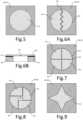
- the pressure safety device of figure 4Ais shown in top view in figure 5A with the burst layer 34 extending over the central cavity 35.
- one or more weakening zones or lines 38 of reduced stress resistancemay be formed in the burst layer 34 as shown in figures 6A, 7 and 8 in top view and in figure 6B in cross section. As shown in figure 6B these lines or zones are created by a local thickness reduction 38 along these lines or zones. This will result in a local weakening of the burst layer and a more controlled rupture along these lines or zones.
- the central cavity 35may be given a polygonal lateral cross section as shown along the embodiment of figure 9 that will lead to a stress concentration in the vicinity of the corners.
- Figure 10A-10Cshow in planar top view and cross section, respectively, a fifth embodiment of a pressure safety device for use in a spray device according to the invention.
- the configuration of this embodimentis similar to that of figure 6A and 6B in that it comprises a semiconductor silicon body 30 on top of which an silicon oxide layer 32 is grown and a silicon nitride burst layer 34 is deposited with a thickness of the order on a few micron.
- the structureis coated or otherwise covered by a flexible thermoplastic polymer layer 42 that sticks to the nitride layer 34.
- paryleneis used for the polymer layer 42 with a thickness of only a few micron or even less than a micron.
- a breaker line or zone 44has been formed in the nitride burst layer 34 in the form of a depression or ditch 44 that extends almost along the entire periphery of the cavity 35 except for a relatively small hinge portion 46. Said ditch extends entirely across the plastic layer 42 to create a peninsula like central portion 45 of the plastic layer and said nitride layer 34.
- the ditch 44delivers a weakness in the nitride burst layer 34 causing the nitride layer 34 to burst at a pressure of the order of a few bar, which is below the normal operating pressure of the spray device.
- the plastic layer 42 on tophas sufficient flexibility and tensile strength to withstand this pressure and will hinge along the hinge portion as shown in figure 10C , while keeping the central portion 45 of the nitride layer 34 to it. This will avoid the loss of any noticeable debris of the nitride burst layer 34 once it bursts, while creating a considerable opening 35 in the support body 30. Due to this enhanced retention of material of the burst layer 34 this embodiment might also be applied down stream of the nozzle body without the risk that debris of the burst layer will interfere with, or enter into the spray that is to be generated by the spray device.
- the closed burst layereffectively closes the pathway between any liquid to be sprayed and the environment before initial use of the device.
- the strength of the burst layeris, however, chosen such that it will burst once it is exposed to the normal operating pressure of the spray device to which the spray nozzle unit is mounted. This will automatically open said pathway without any necessary additional interference by the user and renders the device ready for use.
- the pressure safety deviceneed not be placed in the nozzle holder or spray nozzle unit but may also reside upstream thereof, for instance between a container, containing the fluid to be sprayed, or pumping means of the spray device and the spray nozzle unit or holder.
- the safety device 30 and, particularly, the burst layer 34may be used for the safety device 30 and, particularly, the burst layer 34. This also concerns mutatis mutandis the sieve device and the nozzle device as well as the nozzle unit.
- the beaker layermight as well comprise a polymer foil or metal foil that is attached to a support body, extending over a central opening.
- other thermoplastic materialscan be used than parylene, to cover the burst layer and to form one or more flexible hinges.
- the plastic materialscan be anchored in the micro machined silicon structure by forming anchoring holes or the like.
- one cavitymay be formed in the support body of the safety device, spanned by the same or individual burst layers, to implement several parallel pathways through the device, again to assure breakage of at least one of them below the operating pressure.
- a so called Luer type nozzle unithas been shown for placement on a syringe.
- the nozzle unitmay be give any appropriate design to match a particular spray device, which might, for instance, be a spray cannister, bottle, ampul or any other container holding a certain amount of fluid to be pressurized by means of appropriate pressurizing means of the spray device.
Landscapes
- Containers And Packaging Bodies Having A Special Means To Remove Contents (AREA)
- Nozzles (AREA)
Description
- The present invention relates to a spray device, having a spray nozzle unit, wherein said spray nozzle unit comprises nozzle holder with a cavity having an inlet for receiving a pressurized liquid at an operating pressure and an outlet for releasing a liquid spray during operation, wherein a spray nozzle body is fitted sealingly within said cavity of said nozzle holder, said spray nozzle body having a perforated nozzle layer with at least one spray orifice that extends between an upstream surface and a down stream surface thereof, said upstream surface receiving said pressurized liquid during operation and said at least one spray orifice releasing at least one jet of said liquid spray at said downstream surface of said nozzle layer.
- A spray device of the above kind uses the spray nozzle unit to create a spray, also referred to as mist or aerosol, of extremely fine droplets out of a pressurized liquid. Said liquid may be contained in a container like a bottle, cannister or syringe that is moreover provided with pressurizing means to force said liquid under an appropriate pressure to the inlet of the spray nozzle unit. Often said spray nozzle unit will be fitted with its inlet directly on an outlet of said container and/or of such pressurizing means like a pump or a pressurized propellant. This allows the pressurized liquid to enter the cavity, where it is forced to the nozzle device and through the nozzle layer for generating the spray.
- European patent application
EP 1.747.816 discloses a spray device having a spray nozzle unit, wherein said spray nozzle unit comprises a nozzle holder with a cavity having an inlet for receiving a pressurized liquid at an operating pressure and having an outlet for releasing a liquid spray during operation. A spray nozzle body is fitted sealingly within said cavity of said nozzle holder, said spray nozzle body having a perforated nozzle layer with at least one spray orifice that extends between an upstream surface and a downstream surface thereof. A pressure safety device is provided upstream of said spray nozzle body that comprises a closed burst layer that closes a fluid pathway to said nozzle body but ruptures once a threshold pressure is exceeded. - The spray device according to the invention is particularly suitable for generating a so-called micro-jet spray of very fine droplets, having a controlled pre-defined size. Such micro-jet spray may contain many emitting jets, in which each jet will initially breakup into a mono disperse primary droplet train according to the so-called Rayleigh breakup mechanism. As a result, consecutive primary droplets have a same size and propagate from the nozzle orifice in a same direction, typically the diameter of the primary droplet is 1,85-2,0 times the diameter of the nozzle orifice. Often the corresponding nozzle orifices are provided in a planar substrate yielding jets that are all directed in a same or varying spraying direction, depending on the specific nozzle configuration. Due to possible coalescence of mutually interfering droplets the average droplet size within the spray may eventual grow, but an actual droplet size distribution of the spray nonetheless still remains confined between relatively narrow boundaries.
- The spray nozzle orifices that extend through the spray nozzle layer unavoidably create an open fluid path between the liquid content of the device and the environment. On the one hand this
happens without any further necessary intervention by the patient or user, rendering the device according to the invention extremely convenient and fool-proof for use. - In a particular embodiment the pressure safety device is integrated in the nozzle holder of the spray nozzle unit itself. To that end, a particular embodiment of the spray nozzle device according to the invention is characterized in that said pressure safety device comprises a pressure safety body that is fitted sealingly within said cavity of said nozzle holder between said inlet of said nozzle holder and said spray nozzle body.
- To facilitate an easy in-line testing of the spray nozzle unit as well as a convenient post-assembly of the pressure safety device, a preferred embodiment of the spray device according to the invention is characterized in that said pressure safety device is mounted directly downstream of said inlet, particularly at or near said inlet. In this respect "directly downstream" is meant to indicate that the pressure safety device is the most upstream member within said cavity of said holder and, hence, may be placed as final product finishing the spray nozzle unit.
- To further aid a fluid-tight placement of the pressure safety device, a further preferred embodiment of the spray device according to the invention is characterized in that said pressure safety body is fitted sealingly in an adapter ring, said adapter ring surrounding the pressure safety body and being sealed to an inner wall of said cavity, particularly by fusion or gluing. The adapter ring in that case fills any intervening space between the pressure safety body and the inner wall of said cavity. Moreover, the adapter ring may be sealed inside the cavity using proven sealing techniques, like fusing and gluing. To that end a further preferred embodiment of the spray device according to the invention is characterized in that both said nozzle holder and said adapter ring comprise a suitable plastic, particularly a thermoplastic polymer, more particularly a same plastic.
- In a particular embodiment, wherein said spray nozzle body comprises a first plate body having at least one first cavity extending throughout a thickness thereof, wherein said nozzle layer extends over said at least one first cavity, the spray nozzle device according to the invention is further characterized in that said pressure safety body comprises a second plate body having at least one second cavity extending throughout a thickness thereof, wherein said burst layer extends over said second cavity, and in that said first plate body and said second plate body are fitted sealingly within said cavity of said nozzle holder. The steps necessary for mounting the pressure safety device within the spray nozzle unit are in that case equal or at least similar to the steps used for fitting the nozzle body. This will, hence, add no substantial complexity to the assembly of the spray nozzle unit.
- A further preferred embodiment of the spray device according to the invention is characterized in that said first plate body and said second plate body each comprise a silicon body, and in that said nozzle layer and said burst layer each comprise at least one of a silicon nitride and a silicon oxide layer covering the respective silicon body. In this case not only the assembly of the spray nozzle unit but also the manufacturing of the pressure safety device fits seamlessly into that of the spray nozzle body itself. The materials used for the respective parts of the device are well known in the field of semiconductor manufacturing. As a result, both plate bodies may conveniently be created as (micro)chips using state of the art semiconductor or micro machining manufacturing technology, resulting in a high precision and reliability combined with a very well controlled reproducibility.
- An important factor for the device to function properly is that the burst layer should indeed break below the normal operating pressure of the device. To that end a preferred embodiment of the spray device according to the invention is characterized in that said burst layer is provided with at least one burst zone of reduced stress resistance. The formation of such one or more burst zones creates an intended weakness in the burst layer that promotes a controlled rupture below said operating pressure.
- In a first particular embodiment, the spray device according to the invention is characterized in that said second cavity has a polygonal lateral cross section that is spanned by said burst layer. The polygonal shape of the second cavity gives rise to a stress concentration in and around the corners of the cavity. This will induce a weakness in the burst layer that promotes rupture once it os exposed to the pressurized liquid at the operating pressure of the spray device.
- In a further particular embodiment the spray device according to the invention is thereby characterized in that said at least one burst zone comprises at least one burst line along which said burst layer has a reduced thickness. Especially if these burst lines or zones are formed using high precision semiconductor or micro machining technology, a very well controlled and predictable behaviour of the pressure safety device may be obtained.
- In order top avoid that part of the broken or ruptured burst layer may adversely affect the functioning of the spray nozzle body, a further preferred embodiment of the spray device according to the invention is characterized in that a sieve device is fitted within said cavity between said pressure safety device and said spray nozzle device, said sieve device having a plurality of sieve passages and being capable of intercepting debris of said burst layer. This way the sieve device will prevent any debris of the burst layer, that might otherwise cause clogging or otherwise obstructing a nozzle orifice, from reaching the nozzle body.
- In a further preferred embodiment the device according to the invention is thereby characterized in that said spray nozzle body comprises a first plate body having at least one first cavity extending throughout a thickness thereof, wherein said nozzle layer extends over said at least one first cavity, in that said sieve device comprises a further plate body having at least one cavity extending throughout a thickness thereof and a sieve layer extending over said cavity, said sieve layer having a plurality of sieve passages extending throughout a thickness thereof, similar or smaller in size but of greater number than said at least one spray orifice, and in that said first plate body and said further plate body are fitted sealingly within said cavity of said nozzle holder. The steps necessary for mounting the sieve device within the spray nozzle unit are in that case equal or at least similar to the steps used for fitting the nozzle body itself. This will, hence, add no substantial complexity to the assembly of the spray nozzle unit.
- A further preferred embodiment of the spray device according to the invention is characterized in that said first plate body and said further plate body each comprise a silicon body, and in that said nozzle layer and said sieve layer each comprise at least one of a silicon nitride and a silicon oxide layer covering the respective silicon body. In this case not only the assembly, but also the manufacturing of the sieve device fits seamlessly into that of the spray nozzle unit. The materials used for the respective parts of the device are well known in the field of semiconductor or micro machining manufacturing. As a result, both plate bodies may conveniently be created as (micro)chips using state of the art semiconductor or micro machining manufacturing technology, resulting in a high precision and reliability combined with a very well controlled reproducibility.
- The invention also relates to a spray nozzle unit of the kind as applied in the spray device according to the invention and will now be described in further detail with reference to one or more embodiments and an accompanying drawing. In the drawing:
- Figure 1A
- is a cross section of a first typical example of a spray nozzle unit for use in or on a spray device according to the invention;
- Figure 1B
- is a cross section of a second typical example of a spray nozzle unit for use in or on a spray device according to the invention;
- Figure 2
- is a cross section of a nozzle device as applied in the spray nozzle unit of
figures 1A and 1B ; - Figure 3
- is a cross section of a sieve device as applied in the spray nozzle unit of
figures 1A and 1B ; - Figure 4A,4B
- are cross sections of a pressure safety device as applied in the spray nozzle unit of
figures 1A and 1B in a closed and open condition, respectively; - Figure 4C
- is a top, planar view of the pressure safety device of
figure 4A ; - Figure 6A
- is a top, planar view of a first alternative embodiment of a pressure safety device for use a spray nozzle unit of a spray device according to the invention;
- Figure 6B
- is a cross section of the pressure safety device of
figure 6A ; - Figure 7
- is a top, planar view of a second alternative embodiment of a pressure safety device for use a spray nozzle unit of a spray device according to the invention;
- Figure 8
- is a top, planar view of a third alternative embodiment of a pressure safety device for use a spray nozzle unit of a spray device according to the invention;
- Figure 9
- is a top, planar view of a fourth alternative embodiment of a pressure safety device for use a spray nozzle unit of a spray device according to the invention;
- Figure 10A
- is a top, planar view of a fifth alternative embodiment of a pressure safety device for use a spray nozzle unit of a spray device according to the invention;
- Figure 10B,10C
- are cross sections of the pressure safety device of figure in a closed and open condition, respectively.
- It should be noticed that the drawings are drafted purely schematically and not to scale. In particular, certain dimensions may have been exaggerated to a lesser or greater extent for sake of clarity and understanding. Corresponding parts have been identified with same reference numerals throughout the drawing.
Figure 1A shows an example of a spray nozzle unit as used in a spray device according to the invention. The nozzle unit comprises a solid or assemblednozzle holder 1 of plastic with aninternal cavity 5. In the example shown both thecavity 5 and the body itself have a circular cross-section around acentre line 7, but in practice may each have any convenient design and dimension. Thenozzle unit body 1 may conveniently be formed form a thermoplastic polymer, like polyethylene or poly-propylene, such that it may be manufactured using a conventional thermo-form process, like for instance blow moulding.- In the present example, the spray nozzle unit presents a so-called Luer fitting that may be fitted directly on a syringe or the like that contains or supplies a fluid to be sprayed from a container and that is assumed to be known to skilled person. This fluid is received under an operating pressure of several Bar to over 10 Bar at an
inlet 2 of thecavity 5, forced by suitably selected pressurizing means, to be delivered to aspray nozzle body 10 that is mounted at anoutlet side 3 of the spray nozzle unit. - The
spray nozzle body 10 is depicted in greater detail infigure 3 and comprises a silicon plate body 10 (chip) of several hundreds micron thickness that is covered by asilicon oxide layer 12 and asilicon nitride layer 14. Thesilicon nitride layer 14 has a thickness of one or more micron and spans one ormore cavities 15 formed inside thesilicon body 10 to create a perforated nozzle layer (membrane) that is provided with at least onespray orifice 16 at the location of eachsuch cavity 15. Thecavities 15 have typically a circular cross section of the order of 50 to 100 micron diameter. - The spray orifices 16 extend throughout the thickness of said
nitride layer 14 from an upstream surface to a downstream surface thereof and each have a precisely defined and etched size of a few micron to 10 or more micron. During operation, pressurized fluid that is received by thecavity 5 of said nozzle unit will enter thecavities 15 of saidnozzle chip 10 and will pass through thesenozzle orifices 16. At thedownstream outlet side 3 the liquid will then emanate in the form of a fluid ray that breaks up (so called Rayleigh breakup) into a droplet train of fluid droplets of a well controlled droplet size. This will create a spray (mist) of droplets within an very well defined droplet size distribution. - Preceding the spray nozzle, i.e. upstream, is a
sieve device 20 having a plurality ofsieve passages 26 of equal or smaller size than thespray nozzle orifices 16, as shown in greater detail infigure 3 . These sieve passages protect the nozzle body against clogging as particles or other bodies that might otherwise block a nozzle orifice are effectively blocked and intercepted by the sieve device. Like thenozzle device 10, thesieve device 20 comprises a silicon body (chip) of the order on a few hundred micron thickness in which acavity 25 is created running throughout its thickness. On top of thissilicon body 20 are asilicon oxide layer 22 and asilicon nitride layer 24. The latter extends over saidcavity 25 to form a sieve plate having a great number ofsieve passages 26 that are precisely etched throughout its thickness. This thickness may exceed that of thenozzle layer 14 to gain additional strength. The number ofpassages 26 greatly outnumbers the number ofnozzle orifices 16 in order to guarantee an uninterrupted delivery of fluid to thenozzle body 10. - Both the
nozzle body 10 and thesieve device 20 allow a free flow of both fluid from within the device to the environment as well as of ambient air to within thecavity 5 of the nozzle unit. The latter may be contaminated with micro-organisms, like bacteria, fungi and viruses. In order to prevent evaporation of liquid from the pre filled syringe via the open nozzle chip and to prevent microbial ingrowth into the container, apressure safety device 30 is placed upstream of thesieve device 20 within thecavity 5. This pressure safety device is shown in greater detail infigures 4A and 4B . The pressure safety device contains aclosed burst layer 34 extending over anopening 35 that is in direct communication with theinlet 2 of the nozzle unit. Theclosed burst layer 34 initial seals the flow path to the syringe completely, to prevent premature evaporation of liquid and to protect the content of the syringe or other container to which the nozzle unit is mounted against microbial intrusion, seefigure 4A . - Once a threshold pressure of the burst layer is exceeded, however, it will burst or rupture thus opening said flow path, see
figure 4B . Theburst layer 34 is configured to have a threshold pressure below a normal operating pressure of the spray device in which the nozzle unit is applied, for instance between 2 and 3 Bar, such that this opening of the flow path will occur automatically once the pressure means of the device are actuated by a user and a pressurized liquid is forced under said operating pressure against said burst layer. This will open the flow path to thenozzle device 10 causing the spray device to generate an undisturbed spray. This way the spray nozzle unit has an internal lidding foil, or a 'lidding chip', which is opened at first use. This is a one-time event. At the first use of the spray nozzle unit, it is 'deflowered' but during shelf life there is no open path between the container content and the outside world. - In this example also the pressure safety device has been formed using a similar semiconductor or micro machining manufacturing technology that has also been used for the formation of the
nozzle chip 10 andsieve chip 20. As such thesafety device 30 comprises a silicon semiconductor body with acentral cavity 35 that is spanned by a siliconnitride burst layer 34 of appropriate thickness to allow rupture of this layer below a the operating pressure of the spray device. Thenitride layer 34 is given a thickness of 1 micron or less to assure breakage below the operating pressure. In between thenitride layer 34 and the silicon body is a thinsilicon oxide layer 32. In this example the thickness of the burst layer is chosen below the respective thicknesses of thesieve layer 24 andnozzle layer 14 that are both dimensioned to withstand said operating pressure. - Because of the constructional similarity between the
pressure safety device 30 and thenozzle device 10, not only a similar manufacturing technique but also similar pick-and-place methods and equipment may be used during assembly of the nozzle device for properly positioning and fastening the pressure safety device within thecavity 5 of the nozzle unit. Any potential debris from the rupture of theburst layer 34 will be intercepted by thesieve device 20 and, hence, will not influence the spray behaviour, nor will it be inhaled, ingested or otherwise be administered to the user of the spray device. This order of placement also enables an in line testing with air or another gas of thenozzle device 10 andsieve device 20 after assembly. Thesafety device 30 may in that case be mounted in place afterwards, followed by aporous pre-filter 4 of an appropriate woven or non-woven polymer fabric, like fluffy polypropylene. - An alternative embodiment of a spray nozzle unit with such an integrated pressure safety device is shown in
figure 1B . Also in this case the pressure safety device contains a silicon semiconductor body with a nitride burst layer, similar to that as in the device offigure 1A . In this example, however, the silicon body is not mounted directly in thecavity 5 of thenozzle holder 1, but fitted in a surroundingadapter ring 33. This adapter ring may be formed of a thermoplastic polymer, particularly the same or a similar plastic as the nozzle unit itself, and crosses the space between the smaller silicon body and the internal wall of thecavity 5. This saves chip area, hence, cost, but moreover allows proven fusion techniques, like melting and gluing, for mounting and sealing thesafety device 30 within the cavity after the nozzle unit has been tested with thenozzle body 10 andsieve body 20 in place. In this case the pressure safety device is, moreover, placed upstream of theporous pre-filter 4, but might also be positioned downstream of thepre-filter 4. - The pressure safety device of
figure 4A is shown in top view in figure 5A with theburst layer 34 extending over thecentral cavity 35. In order to promote rupture of the burst layer one or more weakening zones orlines 38 of reduced stress resistance may be formed in theburst layer 34 as shown infigures 6A, 7 and 8 in top view and infigure 6B in cross section. As shown infigure 6B these lines or zones are created by alocal thickness reduction 38 along these lines or zones. This will result in a local weakening of the burst layer and a more controlled rupture along these lines or zones. Alternatively or additionally also thecentral cavity 35 may be given a polygonal lateral cross section as shown along the embodiment offigure 9 that will lead to a stress concentration in the vicinity of the corners. Figure 10A-10C show in planar top view and cross section, respectively, a fifth embodiment of a pressure safety device for use in a spray device according to the invention. The configuration of this embodiment is similar to that offigure 6A and 6B in that it comprises asemiconductor silicon body 30 on top of which ansilicon oxide layer 32 is grown and a siliconnitride burst layer 34 is deposited with a thickness of the order on a few micron. In this embodiment, however, the structure is coated or otherwise covered by a flexiblethermoplastic polymer layer 42 that sticks to thenitride layer 34. in this case parylene is used for thepolymer layer 42 with a thickness of only a few micron or even less than a micron.- A breaker line or
zone 44 has been formed in thenitride burst layer 34 in the form of a depression or ditch 44 that extends almost along the entire periphery of thecavity 35 except for a relativelysmall hinge portion 46. Said ditch extends entirely across theplastic layer 42 to create a peninsula likecentral portion 45 of the plastic layer and saidnitride layer 34. Theditch 44 delivers a weakness in thenitride burst layer 34 causing thenitride layer 34 to burst at a pressure of the order of a few bar, which is below the normal operating pressure of the spray device. - The
plastic layer 42 on top, however, has sufficient flexibility and tensile strength to withstand this pressure and will hinge along the hinge portion as shown infigure 10C , while keeping thecentral portion 45 of thenitride layer 34 to it. This will avoid the loss of any noticeable debris of thenitride burst layer 34 once it bursts, while creating aconsiderable opening 35 in thesupport body 30. Due to this enhanced retention of material of theburst layer 34 this embodiment might also be applied down stream of the nozzle body without the risk that debris of the burst layer will interfere with, or enter into the spray that is to be generated by the spray device. - In all cases the closed burst layer effectively closes the pathway between any liquid to be sprayed and the environment before initial use of the device. The strength of the burst layer is, however, chosen such that it will burst once it is exposed to the normal operating pressure of the spray device to which the spray nozzle unit is mounted. This will automatically open said pathway without any necessary additional interference by the user and renders the device ready for use.
- Although the invention has been describes hereinbefore with reference to merely a few specific embodiments, it will be clear that the invention is by no means limited to these examples. Instead many alternatives and variations are feasible for a skilled person without departing from the scope and spirit of the present invention. As such the pressure safety device need not be placed in the nozzle holder or spray nozzle unit but may also reside upstream thereof, for instance between a container, containing the fluid to be sprayed, or pumping means of the spray device and the spray nozzle unit or holder.
- Other designs, materials and dimensions may be used for the
safety device 30 and, particularly, theburst layer 34. This also concerns mutatis mutandis the sieve device and the nozzle device as well as the nozzle unit. Particularly the beaker layer might as well comprise a polymer foil or metal foil that is attached to a support body, extending over a central opening. Also other thermoplastic materials can be used than parylene, to cover the burst layer and to form one or more flexible hinges. The plastic materials can be anchored in the micro machined silicon structure by forming anchoring holes or the like. Preferably use is made of a bio-compatible plastic in case of medical appliances. - Also more that one cavity may be formed in the support body of the safety device, spanned by the same or individual burst layers, to implement several parallel pathways through the device, again to assure breakage of at least one of them below the operating pressure.
- In the example a so called Luer type nozzle unit has been shown for placement on a syringe. Alternative the nozzle unit may be give any appropriate design to match a particular spray device, which might, for instance, be a spray cannister, bottle, ampul or any other container holding a certain amount of fluid to be pressurized by means of appropriate pressurizing means of the spray device.
Claims (14)
- Spray device comprising a spray nozzle unit (1), wherein said spray nozzle unit comprises nozzle holder with a cavity (5) having an inlet (2) for receiving a pressurized liquid at an operating pressure and an outlet (3) for releasing a liquid spray during operation, wherein a spray nozzle body (10) is fitted sealingly within said cavity of said nozzle holder, said spray nozzle body having a perforated nozzle layer (14) with at least one spray orifice (16) that extends between an upstream surface and a down stream surface thereof, said upstream surface receiving said pressurized liquid during operation and said at least one spray orifice releasing at least one jet of said liquid spray at said downstream surface of said nozzle layer,characterized in that a pressure safety device (30) is provided upstream of said spray nozzle body,in that said pressure safety device comprises a closed burst layer (34) that closes a fluid pathway to said spray nozzle body but ruptures once a threshold pressure is exceeded, andin that said operating pressure exceeds said threshold pressure.
- Spray device according to claim 1,characterized in that said pressure safety device comprises a pressure safety body (30) that is fitted sealingly within said cavity of said nozzle holder, residing between said inlet of said nozzle holder and said spray nozzle body.
- Spray device according to claim 2,characterized in that said pressure safety body is fitted sealingly in an adapter ring (33), said adapter ring surrounding the pressure safety body and being sealed to an inner wall of said cavity, particularly by fusion or gluing.
- Spray device according to claim 3,characterized in that both said nozzle holder (1) and said adapter ring (33) comprise a plastic, particularly a thermoplastic polymer, more particularly a same plastic.
- Spray device according to any of claims 2, 3 and 4,characterized in that said pressure safety device (30) is mounted directly downstream of said inlet (2), particularly at or near said inlet.
- Spray device according to any of claims 2, 3, 4 and 5,characterized in that said spray nozzle body (10) comprises a first plate body having at least one first cavity (15) extending throughout a thickness thereof, wherein said nozzle layer (14) extends over said at least one first cavity,in that said pressure safety body comprises a second plate body (30) having at least one second cavity (35) extending throughout a thickness thereof, wherein said burst layer (34) extends over said second cavity, andin that said first plate body and said second plate body are fitted sealingly within said cavity (5) of said nozzle holder.
- Spray device according to claim 6,characterized in that said first plate body (10) and said second plate body (30) each comprise a silicon body, andin that said nozzle layer (14) and said burst layer (34) each comprise at least one of a silicon nitride and a silicon oxide layer (12,32) covering the respective silicon body.
- Spray device as claimed in claim 6 or 7,characterized in that said second cavity (35) has a polygonal lateral cross section that is spanned by said burst layer.
- Spray device according to any of the preceding claims,characterized in that said burst layer (34) is provided with at least one burst zone (38) of reduced stress resistance.
- Spray device according to claim 9,characterized in that said at least one burst zone comprises at least one burst line along which said burst layer (34) has a reduced thickness.
- Spray device according to any of the preceding claims,characterized in that a sieve device (20) is fitted within said cavity (5) of said nozzle holder between said pressure safety device (30) and said spray nozzle device (10), said sieve device having a plurality of sieve passages and being capable of intercepting debris of said burst layer.
- Spray device according to claim 11,characterized in that said spray nozzle body comprises a first plate body (100 having at least one first cavity (15) extending throughout a thickness thereof, wherein said nozzle layer (14) extends over said at least one first cavity (15),in that said sieve device comprises a further plate body (20) having at least one cavity (25) extending throughout a thickness thereof and a sieve layer (24) extending over said cavity, said sieve layer having a plurality of sieve passages (26) extending throughout a thickness thereof, similar or smaller in size but of greater number than said at least one spray orifice (16), andin that said first plate body and said further plate body are fitted sealingly within said cavity (5) of said nozzle holder (1).
- Spray device according to claim 12,characterized in that said first plate body (10) and said further plate body (20) each comprise a silicon body, andin that said nozzle layer (14) and said sieve layer (24) each comprise at least one of a silicon nitride and a silicon oxide layer (12,22) covering the respective silicon body.
- Spray device according to any of the preceding claims,characterized in that a flexible, particularly plastic retention layer (42) is formed over the burst layer (34), andin that a depression (44) is formed along a peninsula portion of the plastic layer and burst layer, said depression extending through said flexible layer and part of a thickness of said burst layer.
Applications Claiming Priority (2)
| Application Number | Priority Date | Filing Date | Title |
|---|---|---|---|
| NL2021872ANL2021872B1 (en) | 2018-10-24 | 2018-10-24 | Spray device and spray nozzle unit |
| PCT/NL2019/050702WO2020085908A1 (en) | 2018-10-24 | 2019-10-24 | Spray device and spray nozzle unit |
Publications (2)
| Publication Number | Publication Date |
|---|---|
| EP3870372A1 EP3870372A1 (en) | 2021-09-01 |
| EP3870372B1true EP3870372B1 (en) | 2023-12-06 |
Family
ID=66049634
Family Applications (1)
| Application Number | Title | Priority Date | Filing Date |
|---|---|---|---|
| EP19828895.3AActiveEP3870372B1 (en) | 2018-10-24 | 2019-10-24 | Spray device and spray nozzle unit |
Country Status (5)
| Country | Link |
|---|---|
| US (1) | US11975342B2 (en) |
| EP (1) | EP3870372B1 (en) |
| ES (1) | ES2968654T3 (en) |
| NL (1) | NL2021872B1 (en) |
| WO (1) | WO2020085908A1 (en) |
Families Citing this family (2)
| Publication number | Priority date | Publication date | Assignee | Title |
|---|---|---|---|---|
| EP4103332B1 (en)* | 2020-02-13 | 2025-07-02 | SHL Medical AG | Aerosol assembly for a medicament delivery device |
| CN117442826B (en)* | 2023-10-26 | 2024-10-01 | 苏州新劢德医疗器械科技有限公司 | Integrated nozzle structure, assembling method and atomizing device |
Family Cites Families (5)
| Publication number | Priority date | Publication date | Assignee | Title |
|---|---|---|---|---|
| DE3645354C2 (en)* | 1985-09-14 | 2003-05-08 | Pfeiffer Erich Gmbh & Co Kg | Disposable medicament sprayer discharge mechanism |
| EP1747816A3 (en)* | 1999-09-15 | 2007-02-14 | Aradigm Corporation | Pore structures for reduced pressure aerosolization |
| US20040020173A1 (en)* | 2002-07-30 | 2004-02-05 | Cho Steven T. | Low temperature anodic bonding method using focused energy for assembly of micromachined systems |
| EP3157681A1 (en)* | 2014-06-20 | 2017-04-26 | Medspray B.V. | Aerosol or spray device, spray nozzle unit and method of manufacturing the same |
| EP3383550A1 (en)* | 2015-12-04 | 2018-10-10 | Medspray B.V. | Fluidic sprayer |
- 2018
- 2018-10-24NLNL2021872Apatent/NL2021872B1/enactive
- 2019
- 2019-10-24WOPCT/NL2019/050702patent/WO2020085908A1/ennot_activeCeased
- 2019-10-24ESES19828895Tpatent/ES2968654T3/enactiveActive
- 2019-10-24USUS17/288,237patent/US11975342B2/enactiveActive
- 2019-10-24EPEP19828895.3Apatent/EP3870372B1/enactiveActive
Also Published As
| Publication number | Publication date |
|---|---|
| US11975342B2 (en) | 2024-05-07 |
| ES2968654T3 (en) | 2024-05-13 |
| NL2021872B1 (en) | 2020-05-13 |
| WO2020085908A1 (en) | 2020-04-30 |
| EP3870372A1 (en) | 2021-09-01 |
| US20210387209A1 (en) | 2021-12-16 |
Similar Documents
| Publication | Publication Date | Title |
|---|---|---|
| EP3870372B1 (en) | Spray device and spray nozzle unit | |
| US11254488B2 (en) | Spray nozzle chip and a medicament delivery device comprising the same | |
| EP1858777B1 (en) | Aerosol dispenser | |
| CN108602080B (en) | fluid sprayer | |
| KR101717260B1 (en) | Discharge device for liquid media | |
| JP7201695B2 (en) | valve | |
| EP1280715A2 (en) | Nozzle arrangement comprising means for control of fluid droplet size | |
| RU2750789C2 (en) | Capsule for making drinks | |
| JP2018518294A (en) | Micro nozzle assembly with filter | |
| CN112118883B (en) | Nozzle and cartridge assembly | |
| NL2022180B1 (en) | Spray device and spray nozzle unit | |
| NZ556180A (en) | Swirl spray nozzle and insert thereof, with retaining portion of insert to allow it to be retained to nozzle body via O ring | |
| US20200339315A1 (en) | Vented protective cap for a liquid dispenser, venting insert, in particular for a protective cap, liquid dispenser having such a protective cap or such a venting insert, and method for producing a protective cap or a venting insert | |
| EP3914394B1 (en) | Spray nozzle chip and a medicament delivery device comprising the same | |
| JP5878000B2 (en) | Discharge container | |
| JP2003026266A (en) | Liquid pour-out device | |
| JP6617000B2 (en) | Aerosol container injection button |
Legal Events
| Date | Code | Title | Description |
|---|---|---|---|
| STAA | Information on the status of an ep patent application or granted ep patent | Free format text:STATUS: UNKNOWN | |
| STAA | Information on the status of an ep patent application or granted ep patent | Free format text:STATUS: THE INTERNATIONAL PUBLICATION HAS BEEN MADE | |
| PUAI | Public reference made under article 153(3) epc to a published international application that has entered the european phase | Free format text:ORIGINAL CODE: 0009012 | |
| STAA | Information on the status of an ep patent application or granted ep patent | Free format text:STATUS: REQUEST FOR EXAMINATION WAS MADE | |
| 17P | Request for examination filed | Effective date:20210525 | |
| AK | Designated contracting states | Kind code of ref document:A1 Designated state(s):AL AT BE BG CH CY CZ DE DK EE ES FI FR GB GR HR HU IE IS IT LI LT LU LV MC MK MT NL NO PL PT RO RS SE SI SK SM TR | |
| DAV | Request for validation of the european patent (deleted) | ||
| DAX | Request for extension of the european patent (deleted) | ||
| STAA | Information on the status of an ep patent application or granted ep patent | Free format text:STATUS: EXAMINATION IS IN PROGRESS | |
| 17Q | First examination report despatched | Effective date:20220622 | |
| GRAP | Despatch of communication of intention to grant a patent | Free format text:ORIGINAL CODE: EPIDOSNIGR1 | |
| STAA | Information on the status of an ep patent application or granted ep patent | Free format text:STATUS: GRANT OF PATENT IS INTENDED | |
| INTG | Intention to grant announced | Effective date:20230516 | |
| P01 | Opt-out of the competence of the unified patent court (upc) registered | Effective date:20230530 | |
| GRAS | Grant fee paid | Free format text:ORIGINAL CODE: EPIDOSNIGR3 | |
| RIN1 | Information on inventor provided before grant (corrected) | Inventor name:VAN EGMOND, HENRI JOSEPH Inventor name:DE KRUIJF, WILHELMUS PETRUS JOHANNES Inventor name:NIJDAM, WIETZE Inventor name:VAN RIJN, CORNELIS JOHANNES MARIA | |
| GRAA | (expected) grant | Free format text:ORIGINAL CODE: 0009210 | |
| STAA | Information on the status of an ep patent application or granted ep patent | Free format text:STATUS: THE PATENT HAS BEEN GRANTED | |
| AK | Designated contracting states | Kind code of ref document:B1 Designated state(s):AL AT BE BG CH CY CZ DE DK EE ES FI FR GB GR HR HU IE IS IT LI LT LU LV MC MK MT NL NO PL PT RO RS SE SI SK SM TR | |
| REG | Reference to a national code | Ref country code:GB Ref legal event code:FG4D | |
| REG | Reference to a national code | Ref country code:CH Ref legal event code:EP | |
| REG | Reference to a national code | Ref country code:DE Ref legal event code:R096 Ref document number:602019042944 Country of ref document:DE | |
| REG | Reference to a national code | Ref country code:IE Ref legal event code:FG4D | |
| REG | Reference to a national code | Ref country code:NL Ref legal event code:FP | |
| REG | Reference to a national code | Ref country code:LT Ref legal event code:MG9D | |
| PG25 | Lapsed in a contracting state [announced via postgrant information from national office to epo] | Ref country code:GR Free format text:LAPSE BECAUSE OF FAILURE TO SUBMIT A TRANSLATION OF THE DESCRIPTION OR TO PAY THE FEE WITHIN THE PRESCRIBED TIME-LIMIT Effective date:20240307 | |
| PG25 | Lapsed in a contracting state [announced via postgrant information from national office to epo] | Ref country code:LT Free format text:LAPSE BECAUSE OF FAILURE TO SUBMIT A TRANSLATION OF THE DESCRIPTION OR TO PAY THE FEE WITHIN THE PRESCRIBED TIME-LIMIT Effective date:20231206 | |
| PG25 | Lapsed in a contracting state [announced via postgrant information from national office to epo] | Ref country code:LT Free format text:LAPSE BECAUSE OF FAILURE TO SUBMIT A TRANSLATION OF THE DESCRIPTION OR TO PAY THE FEE WITHIN THE PRESCRIBED TIME-LIMIT Effective date:20231206 Ref country code:GR Free format text:LAPSE BECAUSE OF FAILURE TO SUBMIT A TRANSLATION OF THE DESCRIPTION OR TO PAY THE FEE WITHIN THE PRESCRIBED TIME-LIMIT Effective date:20240307 Ref country code:BG Free format text:LAPSE BECAUSE OF FAILURE TO SUBMIT A TRANSLATION OF THE DESCRIPTION OR TO PAY THE FEE WITHIN THE PRESCRIBED TIME-LIMIT Effective date:20240306 | |
| REG | Reference to a national code | Ref country code:ES Ref legal event code:FG2A Ref document number:2968654 Country of ref document:ES Kind code of ref document:T3 Effective date:20240513 | |
| REG | Reference to a national code | Ref country code:AT Ref legal event code:MK05 Ref document number:1637899 Country of ref document:AT Kind code of ref document:T Effective date:20231206 | |
| PG25 | Lapsed in a contracting state [announced via postgrant information from national office to epo] | Ref country code:SE Free format text:LAPSE BECAUSE OF FAILURE TO SUBMIT A TRANSLATION OF THE DESCRIPTION OR TO PAY THE FEE WITHIN THE PRESCRIBED TIME-LIMIT Effective date:20231206 Ref country code:RS Free format text:LAPSE BECAUSE OF FAILURE TO SUBMIT A TRANSLATION OF THE DESCRIPTION OR TO PAY THE FEE WITHIN THE PRESCRIBED TIME-LIMIT Effective date:20231206 Ref country code:NO Free format text:LAPSE BECAUSE OF FAILURE TO SUBMIT A TRANSLATION OF THE DESCRIPTION OR TO PAY THE FEE WITHIN THE PRESCRIBED TIME-LIMIT Effective date:20240306 Ref country code:LV Free format text:LAPSE BECAUSE OF FAILURE TO SUBMIT A TRANSLATION OF THE DESCRIPTION OR TO PAY THE FEE WITHIN THE PRESCRIBED TIME-LIMIT Effective date:20231206 Ref country code:HR Free format text:LAPSE BECAUSE OF FAILURE TO SUBMIT A TRANSLATION OF THE DESCRIPTION OR TO PAY THE FEE WITHIN THE PRESCRIBED TIME-LIMIT Effective date:20231206 | |
| PG25 | Lapsed in a contracting state [announced via postgrant information from national office to epo] | Ref country code:IS Free format text:LAPSE BECAUSE OF FAILURE TO SUBMIT A TRANSLATION OF THE DESCRIPTION OR TO PAY THE FEE WITHIN THE PRESCRIBED TIME-LIMIT Effective date:20240406 | |
| PG25 | Lapsed in a contracting state [announced via postgrant information from national office to epo] | Ref country code:AT Free format text:LAPSE BECAUSE OF FAILURE TO SUBMIT A TRANSLATION OF THE DESCRIPTION OR TO PAY THE FEE WITHIN THE PRESCRIBED TIME-LIMIT Effective date:20231206 Ref country code:CZ Free format text:LAPSE BECAUSE OF FAILURE TO SUBMIT A TRANSLATION OF THE DESCRIPTION OR TO PAY THE FEE WITHIN THE PRESCRIBED TIME-LIMIT Effective date:20231206 | |
| PG25 | Lapsed in a contracting state [announced via postgrant information from national office to epo] | Ref country code:SK Free format text:LAPSE BECAUSE OF FAILURE TO SUBMIT A TRANSLATION OF THE DESCRIPTION OR TO PAY THE FEE WITHIN THE PRESCRIBED TIME-LIMIT Effective date:20231206 | |
| PG25 | Lapsed in a contracting state [announced via postgrant information from national office to epo] | Ref country code:SM Free format text:LAPSE BECAUSE OF FAILURE TO SUBMIT A TRANSLATION OF THE DESCRIPTION OR TO PAY THE FEE WITHIN THE PRESCRIBED TIME-LIMIT Effective date:20231206 Ref country code:SK Free format text:LAPSE BECAUSE OF FAILURE TO SUBMIT A TRANSLATION OF THE DESCRIPTION OR TO PAY THE FEE WITHIN THE PRESCRIBED TIME-LIMIT Effective date:20231206 Ref country code:RO Free format text:LAPSE BECAUSE OF FAILURE TO SUBMIT A TRANSLATION OF THE DESCRIPTION OR TO PAY THE FEE WITHIN THE PRESCRIBED TIME-LIMIT Effective date:20231206 Ref country code:IS Free format text:LAPSE BECAUSE OF FAILURE TO SUBMIT A TRANSLATION OF THE DESCRIPTION OR TO PAY THE FEE WITHIN THE PRESCRIBED TIME-LIMIT Effective date:20240406 Ref country code:EE Free format text:LAPSE BECAUSE OF FAILURE TO SUBMIT A TRANSLATION OF THE DESCRIPTION OR TO PAY THE FEE WITHIN THE PRESCRIBED TIME-LIMIT Effective date:20231206 Ref country code:CZ Free format text:LAPSE BECAUSE OF FAILURE TO SUBMIT A TRANSLATION OF THE DESCRIPTION OR TO PAY THE FEE WITHIN THE PRESCRIBED TIME-LIMIT Effective date:20231206 Ref country code:AT Free format text:LAPSE BECAUSE OF FAILURE TO SUBMIT A TRANSLATION OF THE DESCRIPTION OR TO PAY THE FEE WITHIN THE PRESCRIBED TIME-LIMIT Effective date:20231206 | |
| PG25 | Lapsed in a contracting state [announced via postgrant information from national office to epo] | Ref country code:PT Free format text:LAPSE BECAUSE OF FAILURE TO SUBMIT A TRANSLATION OF THE DESCRIPTION OR TO PAY THE FEE WITHIN THE PRESCRIBED TIME-LIMIT Effective date:20240408 Ref country code:PL Free format text:LAPSE BECAUSE OF FAILURE TO SUBMIT A TRANSLATION OF THE DESCRIPTION OR TO PAY THE FEE WITHIN THE PRESCRIBED TIME-LIMIT Effective date:20231206 | |
| PG25 | Lapsed in a contracting state [announced via postgrant information from national office to epo] | Ref country code:PT Free format text:LAPSE BECAUSE OF FAILURE TO SUBMIT A TRANSLATION OF THE DESCRIPTION OR TO PAY THE FEE WITHIN THE PRESCRIBED TIME-LIMIT Effective date:20240408 Ref country code:PL Free format text:LAPSE BECAUSE OF FAILURE TO SUBMIT A TRANSLATION OF THE DESCRIPTION OR TO PAY THE FEE WITHIN THE PRESCRIBED TIME-LIMIT Effective date:20231206 | |
| REG | Reference to a national code | Ref country code:DE Ref legal event code:R097 Ref document number:602019042944 Country of ref document:DE | |
| PG25 | Lapsed in a contracting state [announced via postgrant information from national office to epo] | Ref country code:DK Free format text:LAPSE BECAUSE OF FAILURE TO SUBMIT A TRANSLATION OF THE DESCRIPTION OR TO PAY THE FEE WITHIN THE PRESCRIBED TIME-LIMIT Effective date:20231206 | |
| PLBE | No opposition filed within time limit | Free format text:ORIGINAL CODE: 0009261 | |
| STAA | Information on the status of an ep patent application or granted ep patent | Free format text:STATUS: NO OPPOSITION FILED WITHIN TIME LIMIT | |
| PG25 | Lapsed in a contracting state [announced via postgrant information from national office to epo] | Ref country code:SI Free format text:LAPSE BECAUSE OF FAILURE TO SUBMIT A TRANSLATION OF THE DESCRIPTION OR TO PAY THE FEE WITHIN THE PRESCRIBED TIME-LIMIT Effective date:20231206 | |
| PG25 | Lapsed in a contracting state [announced via postgrant information from national office to epo] | Ref country code:SI Free format text:LAPSE BECAUSE OF FAILURE TO SUBMIT A TRANSLATION OF THE DESCRIPTION OR TO PAY THE FEE WITHIN THE PRESCRIBED TIME-LIMIT Effective date:20231206 Ref country code:DK Free format text:LAPSE BECAUSE OF FAILURE TO SUBMIT A TRANSLATION OF THE DESCRIPTION OR TO PAY THE FEE WITHIN THE PRESCRIBED TIME-LIMIT Effective date:20231206 | |
| 26N | No opposition filed | Effective date:20240909 | |
| PGFP | Annual fee paid to national office [announced via postgrant information from national office to epo] | Ref country code:NL Payment date:20241025 Year of fee payment:6 | |
| PGFP | Annual fee paid to national office [announced via postgrant information from national office to epo] | Ref country code:DE Payment date:20241021 Year of fee payment:6 | |
| PGFP | Annual fee paid to national office [announced via postgrant information from national office to epo] | Ref country code:GB Payment date:20241018 Year of fee payment:6 | |
| PGFP | Annual fee paid to national office [announced via postgrant information from national office to epo] | Ref country code:FR Payment date:20241030 Year of fee payment:6 | |
| PGFP | Annual fee paid to national office [announced via postgrant information from national office to epo] | Ref country code:IT Payment date:20241025 Year of fee payment:6 Ref country code:ES Payment date:20241128 Year of fee payment:6 | |
| REG | Reference to a national code | Ref country code:CH Ref legal event code:PL | |
| PG25 | Lapsed in a contracting state [announced via postgrant information from national office to epo] | Ref country code:MC Free format text:LAPSE BECAUSE OF FAILURE TO SUBMIT A TRANSLATION OF THE DESCRIPTION OR TO PAY THE FEE WITHIN THE PRESCRIBED TIME-LIMIT Effective date:20231206 | |
| PG25 | Lapsed in a contracting state [announced via postgrant information from national office to epo] | Ref country code:BE Free format text:LAPSE BECAUSE OF NON-PAYMENT OF DUE FEES Effective date:20241031 Ref country code:LU Free format text:LAPSE BECAUSE OF NON-PAYMENT OF DUE FEES Effective date:20241024 | |
| PG25 | Lapsed in a contracting state [announced via postgrant information from national office to epo] | Ref country code:CH Free format text:LAPSE BECAUSE OF NON-PAYMENT OF DUE FEES Effective date:20241031 | |
| REG | Reference to a national code | Ref country code:BE Ref legal event code:MM Effective date:20241031 | |
| PG25 | Lapsed in a contracting state [announced via postgrant information from national office to epo] | Ref country code:FI Free format text:LAPSE BECAUSE OF FAILURE TO SUBMIT A TRANSLATION OF THE DESCRIPTION OR TO PAY THE FEE WITHIN THE PRESCRIBED TIME-LIMIT Effective date:20231207 |