EP3868314A1 - Surgical cutting instrument with distal suction capability - Google Patents
Surgical cutting instrument with distal suction capabilityDownload PDFInfo
- Publication number
- EP3868314A1 EP3868314A1EP21169129.0AEP21169129AEP3868314A1EP 3868314 A1EP3868314 A1EP 3868314A1EP 21169129 AEP21169129 AEP 21169129AEP 3868314 A1EP3868314 A1EP 3868314A1
- Authority
- EP
- European Patent Office
- Prior art keywords
- cutting blade
- cutting
- suction
- inner cutting
- distal end
- Prior art date
- Legal status (The legal status is an assumption and is not a legal conclusion. Google has not performed a legal analysis and makes no representation as to the accuracy of the status listed.)
- Granted
Links
Images


Classifications
- A—HUMAN NECESSITIES
- A61—MEDICAL OR VETERINARY SCIENCE; HYGIENE
- A61B—DIAGNOSIS; SURGERY; IDENTIFICATION
- A61B10/00—Instruments for taking body samples for diagnostic purposes; Other methods or instruments for diagnosis, e.g. for vaccination diagnosis, sex determination or ovulation-period determination; Throat striking implements
- A61B10/02—Instruments for taking cell samples or for biopsy
- A61B10/0233—Pointed or sharp biopsy instruments
- A61B10/0266—Pointed or sharp biopsy instruments means for severing sample
- A61B10/0275—Pointed or sharp biopsy instruments means for severing sample with sample notch, e.g. on the side of inner stylet
- A—HUMAN NECESSITIES
- A61—MEDICAL OR VETERINARY SCIENCE; HYGIENE
- A61B—DIAGNOSIS; SURGERY; IDENTIFICATION
- A61B10/00—Instruments for taking body samples for diagnostic purposes; Other methods or instruments for diagnosis, e.g. for vaccination diagnosis, sex determination or ovulation-period determination; Throat striking implements
- A61B10/02—Instruments for taking cell samples or for biopsy
- A61B10/0233—Pointed or sharp biopsy instruments
- A61B10/0283—Pointed or sharp biopsy instruments with vacuum aspiration, e.g. caused by retractable plunger or by connected syringe
- A—HUMAN NECESSITIES
- A61—MEDICAL OR VETERINARY SCIENCE; HYGIENE
- A61B—DIAGNOSIS; SURGERY; IDENTIFICATION
- A61B17/00—Surgical instruments, devices or methods
- A61B17/16—Instruments for performing osteoclasis; Drills or chisels for bones; Trepans
- A61B17/1604—Chisels; Rongeurs; Punches; Stamps
- A—HUMAN NECESSITIES
- A61—MEDICAL OR VETERINARY SCIENCE; HYGIENE
- A61B—DIAGNOSIS; SURGERY; IDENTIFICATION
- A61B17/00—Surgical instruments, devices or methods
- A61B17/32—Surgical cutting instruments
- A61B17/320016—Endoscopic cutting instruments, e.g. arthroscopes, resectoscopes
- A61B17/32002—Endoscopic cutting instruments, e.g. arthroscopes, resectoscopes with continuously rotating, oscillating or reciprocating cutting instruments
- A61B2017/320024—Morcellators, e.g. having a hollow cutting tube with an annular cutter for morcellating and removing tissue
- A—HUMAN NECESSITIES
- A61—MEDICAL OR VETERINARY SCIENCE; HYGIENE
- A61B—DIAGNOSIS; SURGERY; IDENTIFICATION
- A61B2217/00—General characteristics of surgical instruments
- A61B2217/002—Auxiliary appliance
- A61B2217/005—Auxiliary appliance with suction drainage system
Definitions
- This disclosurerelates to surgical instruments, and in particular to surgical cutting instruments that use suction, for example, powered shavers, microdebriders and dissector blades.
- Surgical apparatus used to shave, cut, resect, abrade and/or remove tissue, bone and/or other bodily materialsare known.
- Such surgical apparatuscan include a cutting surface, such as a rotating blade disposed on an elongated inner tube that is rotated within an elongated outer tube having a cutting window.
- the inner and outer tubestogether form a surgical cutting instrument or unit.
- the elongated outer tubeincludes a distal end defining an opening or cutting window disposed at a side of the distal end of the outer tube.
- the cutting window of the outer tubeexposes the cutting surface of the inner tube (located at a side of the distal end of the inner tube) to tissue, bone and/or any other bodily materials to be removed.
- a powered handpieceis used to rotate the inner tube with respect to the outer tube while an outer tube hub (connected to the proximal end of the outer tube) is fixed to the handpiece and an inner tube hub (connected to the proximal end of the inner tube) is loosely held in place by the powered handpiece.
- the inner tubeis hollow and has a cutting window on a side surface of its distal end such that tissue, bone, etc. will be cut or shaved as the cutting window of the inner tube aligns with and then becomes misaligned with the cutting window of the outer tube as the inner tube is rotated within the outer tube.
- the cutting devicenibbles or takes away small pieces of the bone, tissue, etc. as the inner tube is rotated within the outer tube.
- a vacuumis applied through the inner tube such that the bodily material that is to be cut, shaved, etc. is drawn into the windows of the inner and outer tubes when those windows become aligned, thereby facilitating the cutting, shaving, etc. of the tissue, which then travels through the inner tube due to the suction.
- an irrigation fluidwhich can include a liquid, to the surgical site via a passage provided between the inner and outer tubes.
- US 2005/096649 A1discloses a surgical micro-resecting instrument including an outer tubular member, an inner tubular member, a hub assembly and an electrical insulator.
- the outer tubular memberis formed of an electrically conductive material and defines a proximal section, a distal section and a lumen.
- the inner tubular memberis disposed within the lumen and defines a distal portion that forms a cutting tip.
- GB 2 042 902 Adiscloses a surgical instrument for remote cutting which comprises coaxial inner and outer tubes, the inner tube being rotatably driven whilst the outer tube is stationary.
- the inner and outer tubeshave windows in their side walls at their distal ends providing diverging cutting edges.
- US 5 112 299 Adiscloses an arthroscopic surgery instrument which includes an elongated outer sheath member having substantially fully open distal and proximal ends, and an inner hollow cylindrical cutting blade member rotatable within the sheath member.
- An aspiratorcommunicates with the interior space of the cutting blade member to remove tissue severed by the co-operable cutting action of the blade and sheath members.
- US 6 419 684 B1discloses an end-cutting arthroscopic shaver blade having a tubular inner member rotatable within a tubular outer member.
- the distal ends of each of the tubular membersare provided with at least two notches each of which has longitudinally extending sides provided with cutting edges.
- US 2005/070818 A1discloses a biopsy device suitable for collection of a tissue sample from a biopsy site in a body lumen.
- the biopsy devicein comprises a combination of an introducer assembly, a cutter assembly, and an endoscope assembly that coact with one another.
- the introducer assemblyincludes a hollow sheath having a distal end portion defining an aperture suitable for receiving a tissue mass therein.
- the cutter assemblyincludes a cutter tube having a distal end portion with a cutting edge. The cutter tube is sized to fit axially within the introducer sheath.
- the surgeonwishes to apply suction to the surgical site without performing cutting with the surgical instrument. This usually is done by withdrawing the surgical instrument and inserting a dedicated suction device (for example, a suction wand which is a tube to which suction is applied).
- a dedicated suction devicefor example, a suction wand which is a tube to which suction is applied.
- exchanging the surgical tool for the dedicated suction deviceis time-consuming.
- insertion and removal of instruments into the patientcan cause trauma and irritation to the passage of the patient, and thus it is desirable to minimize the number of times that surgical instruments need to be withdrawn and inserted/reinserted into the patient.
- the surgeoncan use the surgical cutting instrument as a suction device, for example, by stopping rotation of the inner cutting tube while continuing to apply suction through the inner tube.
- the pedalor other control device which controls the rotation of the inner tube
- the surgeoncan cause the cutting windows of the inner and outer tubes to be aligned with each other such that suction can be applied to the surgical site through the aligned windows of the inner and outer tubes.
- the windows of the inner and outer tubesare cutting surfaces (and typically include serrations)
- most surgeonschoose not to use the surgical cutting tool as a suctioning device because tissue adjacent to the outer tube window tends to be drawn into the window and partially cut and/or irritated by the cutting surfaces of the inner and outer tubes.
- the suctionis applied from the side of the distal end of the tube, which is not optimal.
- Most suction wandsapply the suction from the very end of the tip such that suction is applied at the very tip of the suction wand.
- a surgical instrument that performs cuttingalso can function as a suction wand. This is achieved by providing the surgical instrument with a suction aperture at the distal-most tip of the surgical instrument such that a longitudinal axis of the surgical instrument passes through the suction aperture.
- the surgical instrumentincludes a first cutting blade and a second cutting blade.
- the first cutting bladeincludes a tubular body having a proximal end and a distal end, with a cutting window disposed at a side of the first cutting blade near the distal end.
- the second cutting bladeincludes a tubular body having a proximal end and a distal end, with a cutting window disposed at a side of the second cutting blade near the distal end.
- the second cutting bladeis rotatably disposed inside of the first cutting blade such that the surgical instrument cuts tissue by rotating the second cutting blade within the first cutting blade while a vacuum is applied through an internal bore of the second cutting blade to draw the tissue into the cutting windows of the first and second cutting blades and sever the tissue by rotation of the second cutting blade.
- the distal end of the first cutting bladeincludes a first suction aperture through which a longitudinal axis of the first cutting blade extends.
- the distal end of the second cutting bladeincludes a second suction aperture through which a longitudinal axis of the second cutting blade extends.
- the surgical instrumentcan be used as a suction tool by applying the vacuum through the internal bore of the second cutting blade while the second cutting blade is stopped from rotating with the cutting windows of the first and second cutting blades misaligned with each other so that the vacuum is applied through the first and second suction apertures.
- most of the suctionis applied through the cutting windows because they are located closer to the vacuum source than are the suction apertures (that is, the cutting windows are proximal to the suction apertures).
- the cutting operationcan be performed as usual.
- a diameter of the first suction apertureis equal to or smaller than a diameter of the second suction aperture.
- the first and second cutting bladespreferably are made from a sterilizable material.
- the sterilizable materialis a metal such as stainless steel.
- a surgical methodincludes inserting the surgical instrument described above into a passage of a patient and then performing a suctioning operation with the surgical instrument.
- the suctioning operationincludes positioning the second cutting blade relative to the first cutting blade so that the cutting windows of the first and second cutting blades are misaligned with each other so that the internal bore of the second cutting blade does not communicate with the passage of the patient through either of the cutting windows of the first and second cutting blades.
- the methodfurther includes applying a vacuum through the internal bore of the second cutting blade to draw material from the passage of the patient into the internal bore of the second cutting blade through the first and second suction apertures. The first and second cutting blades are not rotated relative to each other during the suctioning operation.
- the second cutting bladecan be positioned relative to the first cutting blade so that the cutting windows of the first and second cutting blades are misaligned with each other by the surgeon operating the controls of the surgical instrument (for example, by operating a foot pedal) while observing the distal tip of the cutting instrument (for example, with an endoscope as is typically used to observe the surgical procedure) until the cutting window of the inner, second cutting blade is misaligned with the cutting window of the outer, first cutting blade such that the back side of the second cutting blade opposite to the window substantially blocks the window of the first cutting blade.
- the method of suctioningcan be performed after the surgical instrument has been used for cutting and/or before the surgical instrument has been used for cutting. In either case, it is unnecessary to withdraw the cutting instrument when switching between a cutting operation and a suctioning operation. Furthermore, a separate suction wand may not be needed.
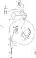
- Fig. 1is a schematic of a powered surgical tool system. Except for the tip of the cutting tool, to be described hereafter, the system may be in accordance with the system described in U.S. Patent No. 7,247,161 , the disclosure of which is incorporated herein by reference in its entirety. Another system to which the invention is applicable is described in U.S. Patent No. 7,318,831 , the disclosure of which is incorporated herein by reference in its entirety.
- the powered surgical tool system 1includes a handle 2, a footswitch 4 (with pedal 12), fluid (liquid and/or gas) source 22, suction source 28, a control unit 6, fluid pump 5 and a fluid inlet/irrigation outlet 7.
- the systemis supplied with power from a power source 16 such as a wall outlet.
- the suction source 28may be an external suction source such as provided by attachment to a facility suction outlet provided on a wall.
- the handle 2is connected, at its distal end, to a surgical instrument 8.
- the surgical instrument 8 in this embodimentincludes a cutting tip at its distal end 8A that is used, for example, to cut, shave, remove, resect and/or abrade tissue, bone and/or other bodily materials.
- Fig. 2illustrates a perspective view of an exemplary embodiment of the surgical instrument 8 in accordance with aspects of the invention.
- the instrument 8incorporates an inner tube 9 and an outer tube 10.
- an inner tube hub 13is formed on the second end 14 of the inner tube 9 and an outer tube hub 15 is formed on the second end 17 of the outer tube 10.
- the inner tube 9is inserted into a fluid passage 20 formed within the outer tube 10 so that the inner tube 9 is co-axially disposed within the outer tube 10 until the external distal tip of the inner tube 9 contacts the internal distal surface of the outer tube 10.
- the outer tube 10has a larger diameter than the inner tube 9, thus allowing for insertion of the inner tube 9 within the outer tube 10.
- the inner and outer tubeswill be pre-assembled prior to delivery to the customer. Thus, a customer will most likely not be inserting the inner tube into the outer tube.
- the inner and outer tube hubs 13, 15couple the inner and outer tubes 9, 10, respectively, to the handle 2. Once coupled to the handle 2, the outer tube 10 will be fixed relative to the handle 2, but the inner tube 9 will be rotatable relative to the outer tube 10 and the handle 2.
- Fig. 3is a perspective view of the distal tip 8a of the surgical instrument 8.
- Fig. 3shows the inner tube 9 retracted slightly from its usual position so that the structure of the distal tips of both the inner tube 9 and the outer tube 10 can be more readily seen.
- the outer tube 10includes a cutting window 60 disposed at a side of its distal end.
- the outer tube 10also can be referred to as a first cutting blade.
- the inner tube 9also includes a cutting window 30 disposed at a side of its distal end.
- the inner tube 9also can be referred to as a second cutting blade.
- the edges of the cutting windows 30 and 60can be serrated, smooth or a combination of serrated and smooth to form cutting surfaces.
- Each of the inner and outer tubes 9, 10also includes a suction aperture at its distal end as shown even more clearly in Figs. 4 and 5 .
- the inner cutting blade 9rotates within the outer cutting blade 10, and thus as the inner cutting blade 9 rotates, the cutting windows 30 and 60 become aligned with each other as shown in Fig. 4 and then become misaligned with each other as shown in Fig. 5 .
- the side of the inner tube 9 distal tip opposite from the cutting window 30blocks the cutting window 60 of the outer cutting blade 10, as will be described in more detail below.
- the first, or outer cutting blade 10thus is a tubular body having a proximal end and a distal end, with a cutting window 60 disposed at a side of the first cutting blade 10 near the distal end.
- the outer cutting blade 10also includes a suction aperture 40 at its distal-most end through which a longitudinal axis LA of the outer tube cutting blade 10 extends.
- the inner, second cutting blade 9is a tubular body having a proximal end and a distal end, with cutting window 30 disposed at a side of its distal end.
- the second, inner cutting blade 9is rotatably disposed inside of the first, outer cutting blade 10 such that the surgical instrument 8 cuts tissue by rotating the second, inner cutting blade 9 within the first, outer cutting blade 10 while a vacuum is applied through an internal bore 25 of the cutting blade 9 to draw the tissue into the cutting windows 30 and 60 of the cutting blades 9 and 10 and sever the tissue by rotation of the cutting blade 9.
- the inner cutting blade 9also includes a suction aperture 50 at its distal-most end through which a longitudinal axis LA of the inner tube cutting blade 9 extends.
- the surgical instrument 8can be used as a suction tool by applying the vacuum through the internal bore 25 of the cutting blade 9 while the cutting blade 9 is stopped from rotating and the cutting windows 30 and 60 of the cutting blades 9 and 10 are misaligned with each other as shown in Fig. 5 so that the vacuum is applied through a suction passage defined by the first and second suction apertures 40 and 50.
- the surgeon operating the instrument 8can cause the windows 30 and 60 to become oriented in the misaligned state shown in Fig. 5 by, for example, tapping on the pedal 12 that controls the instrument to cause incremental rotation of the inner cutting blade 9 while observing the distal tip of the instrument, for example, by an endoscope, which usually also is disposed at the operating site, until the windows 30 and 60 obtain the state shown in Fig.
- irrigation fluidalso could be supplied through bore 20 when in the state shown in Fig. 5 .
- the suction apertures 40 and 50it is undesirable for the suction apertures 40 and 50 to function like a cutting element (like the cutting windows 30 and 60).
- the diameter of the suction aperture 40 provided on the outer cutting blade 10be equal to or smaller than a diameter of the suction aperture 50 provided on the inner cutting blade 9.
- suction aperture 40By making the diameter of the inner suction aperture (aperture 50) on the rotating cutting blade 9 equal to or larger than the diameter of the outer suction aperture (suction aperture 40), the suction apertures 40 and 50 will not function as a cutting device because tissue will not be pinched between the two apertures 40 and 50, or otherwise cut or damaged by those apertures when the instrument is being used as a suction wand and when the instrument is being used as a cutting tool with the inner blade 9 rotating.
- suction aperture 40is smaller than suction aperture 50.
- the edges of the apertures 40 and 50also can be rounded to further keep them from cutting tissue. However, the apertures do not cut tissue even if they are not rounded.
- the apertures 40 and 50do not function to cut tissue is because the apertures 40 and 50 remain aligned with each other even while the inner cutting blade 9 rotates. Due to such alignment, the open suction passage (defined by apertures 40 and 50) exists between the internal bore 25 and an area external of the surgical instrument (that is, an area distal of the surgical instrument tip) through the suction apertures 40 and 50 both when the cutting blade 9 does not rotate and when the cutting blade 9 rotates within the cutting blade 10. In this regard, the suction aperture 50 at the distal end of the inner cutting blade 9 remains in fluid communication with the suction aperture 40 at the distal end of the outer cutting blade 10 as the inner cutting blade 9 rotates, and when it is stationary.
- the distal ends of the cutting blades 9 and 10are substantially spherical.
- the distal ends of the blades 9 and 10could be flat, with the first and second apertures 40 and 50 being disposed on flat portions of those blades.
- spherical tipsare preferred to ease insertion into the patient.
- the cutting blades 9 and 10are made from a sterilizable material.
- the sterilizable materialis a metal such as stainless steel.
- the surgical instrument 8When the instrument 8 is used for surgery, the surgical instrument 8 is inserted into a passage of a patient. Either before or after (or both before and after) a cutting operation is performed, the surgical instrument 8 can be used to perform a suctioning operation.
- the suctioning operationincludes positioning the inner blade 9 relative to the outer blade 10 so that the cutting windows 30 and 60 are misaligned with each other so that the internal bore 25 of the cutting blade 9 does not communicate with the passage of the patient into which the surgical instrument is inserted through either of the cutting windows 30 and 60.
- a vacuum applied through the internal bore 25 of the inner cutting blade 9draws material from the passage of the patient into the internal bore 25 through the suction passage defined by the first and second suction apertures 40 and 50.
- the inner cutting blade 9is not rotated relative to outer cutting blade 10.
- the inner and outer cutting blades 9 and 10are straight.
- the surgical instrument 8can have one or more bends in it such that it is not straight.
- the inner cutting blade 9would be flexible.
- Flexible hollow cutting bladesare known and used with curved cutting instruments. See, for example, U.S. Patent No. 4,646,738 , the disclosure of which is incorporated herein by reference in its entirety, and see, for example, U.S. Patent No. 5,707,350 , the disclosure of which is incorporated herein by reference in its entirety.
- the outer cutting blade 10included an open distal end defined by a suction aperture 40 formed through an otherwise closed portion at the distal tip of the outer cutting blade 10.
- the open distal end of the outer cutting blade 10could be formed by providing an open-ended outer cutting blade 10 (rather than a closed portion having an aperture formed through it). That is, the opening provided at the distal end of the outer cutting blade 10 need not be an aperture that is completely surrounded by wall structure of the outer cutting blade, but instead could be only partially surrounded by wall structure of the outer cutting blade.
- the suction aperture 40does need to be perfectly circular, but could have other shapes.
- FIG. 4Another option would be to form the surgical instrument with no suction aperture at the distal end of the inner cutting blade 9, but to only provide a suction aperture through the distal end of the outer cutting blade 10 at a location that is offset from the longitudinal axis LA.
- Such a suction aperturewould be disposed so as to be covered by and closed by the inner cutting blade 9 when the cutting windows are aligned with each other (the Fig. 4 orientation), but would be uncovered by the distal tip portion of the inner cutting blade 9 when the cutting windows of the inner and outer cutting blades 9 and 10 are misaligned with each other (the Fig. 5 orientation).
- a structureis disfavored because it is feared that the suction aperture in the outer cutting blade will function to cut tissue when the inner cutting blade is rotating within the outer cutting blade (i.e., during a cutting operation).
Landscapes
- Health & Medical Sciences (AREA)
- Life Sciences & Earth Sciences (AREA)
- Surgery (AREA)
- Biomedical Technology (AREA)
- General Health & Medical Sciences (AREA)
- Heart & Thoracic Surgery (AREA)
- Medical Informatics (AREA)
- Molecular Biology (AREA)
- Veterinary Medicine (AREA)
- Animal Behavior & Ethology (AREA)
- Engineering & Computer Science (AREA)
- Public Health (AREA)
- Pathology (AREA)
- Orthopedic Medicine & Surgery (AREA)
- Nuclear Medicine, Radiotherapy & Molecular Imaging (AREA)
- Dentistry (AREA)
- Oral & Maxillofacial Surgery (AREA)
- Surgical Instruments (AREA)
Abstract
Description
- This disclosure relates to surgical instruments, and in particular to surgical cutting instruments that use suction, for example, powered shavers, microdebriders and dissector blades.
- Surgical apparatus used to shave, cut, resect, abrade and/or remove tissue, bone and/or other bodily materials are known. Such surgical apparatus can include a cutting surface, such as a rotating blade disposed on an elongated inner tube that is rotated within an elongated outer tube having a cutting window. The inner and outer tubes together form a surgical cutting instrument or unit. In general, the elongated outer tube includes a distal end defining an opening or cutting window disposed at a side of the distal end of the outer tube. The cutting window of the outer tube exposes the cutting surface of the inner tube (located at a side of the distal end of the inner tube) to tissue, bone and/or any other bodily materials to be removed. A powered handpiece is used to rotate the inner tube with respect to the outer tube while an outer tube hub (connected to the proximal end of the outer tube) is fixed to the handpiece and an inner tube hub (connected to the proximal end of the inner tube) is loosely held in place by the powered handpiece.
- In some instruments the inner tube is hollow and has a cutting window on a side surface of its distal end such that tissue, bone, etc. will be cut or shaved as the cutting window of the inner tube aligns with and then becomes misaligned with the cutting window of the outer tube as the inner tube is rotated within the outer tube. In this regard, it can be said that the cutting device nibbles or takes away small pieces of the bone, tissue, etc. as the inner tube is rotated within the outer tube.
- In some instruments a vacuum is applied through the inner tube such that the bodily material that is to be cut, shaved, etc. is drawn into the windows of the inner and outer tubes when those windows become aligned, thereby facilitating the cutting, shaving, etc. of the tissue, which then travels through the inner tube due to the suction. It also is common to supply an irrigation fluid, which can include a liquid, to the surgical site via a passage provided between the inner and outer tubes.
US 2005/096649 A1 discloses a surgical micro-resecting instrument including an outer tubular member, an inner tubular member, a hub assembly and an electrical insulator. The outer tubular member is formed of an electrically conductive material and defines a proximal section, a distal section and a lumen. The inner tubular member is disposed within the lumen and defines a distal portion that forms a cutting tip.GB 2 042 902 AUS 5 112 299 A discloses an arthroscopic surgery instrument which includes an elongated outer sheath member having substantially fully open distal and proximal ends, and an inner hollow cylindrical cutting blade member rotatable within the sheath member. An aspirator communicates with the interior space of the cutting blade member to remove tissue severed by the co-operable cutting action of the blade and sheath members.US 6 419 684 B1 discloses an end-cutting arthroscopic shaver blade having a tubular inner member rotatable within a tubular outer member. The distal ends of each of the tubular members are provided with at least two notches each of which has longitudinally extending sides provided with cutting edges.US 2005/070818 A1 discloses a biopsy device suitable for collection of a tissue sample from a biopsy site in a body lumen. The biopsy device in comprises a combination of an introducer assembly, a cutter assembly, and an endoscope assembly that coact with one another. The introducer assembly includes a hollow sheath having a distal end portion defining an aperture suitable for receiving a tissue mass therein. The cutter assembly includes a cutter tube having a distal end portion with a cutting edge. The cutter tube is sized to fit axially within the introducer sheath.- Many times during surgery, the surgeon wishes to apply suction to the surgical site without performing cutting with the surgical instrument. This usually is done by withdrawing the surgical instrument and inserting a dedicated suction device (for example, a suction wand which is a tube to which suction is applied). However, exchanging the surgical tool for the dedicated suction device is time-consuming. Furthermore, insertion and removal of instruments into the patient can cause trauma and irritation to the passage of the patient, and thus it is desirable to minimize the number of times that surgical instruments need to be withdrawn and inserted/reinserted into the patient.
- It is conceivable that the surgeon can use the surgical cutting instrument as a suction device, for example, by stopping rotation of the inner cutting tube while continuing to apply suction through the inner tube. By careful operation of the pedal (or other control device) which controls the rotation of the inner tube, the surgeon can cause the cutting windows of the inner and outer tubes to be aligned with each other such that suction can be applied to the surgical site through the aligned windows of the inner and outer tubes. However, because the windows of the inner and outer tubes are cutting surfaces (and typically include serrations), most surgeons choose not to use the surgical cutting tool as a suctioning device because tissue adjacent to the outer tube window tends to be drawn into the window and partially cut and/or irritated by the cutting surfaces of the inner and outer tubes. Additionally, because the cutting windows of the inner and outer tubes are disposed on a side surface of the distal tips of the inner and outer tubes, the suction is applied from the side of the distal end of the tube, which is not optimal. Most suction wands apply the suction from the very end of the tip such that suction is applied at the very tip of the suction wand.
- According to an aspect of the invention, a surgical instrument that performs cutting also can function as a suction wand. This is achieved by providing the surgical instrument with a suction aperture at the distal-most tip of the surgical instrument such that a longitudinal axis of the surgical instrument passes through the suction aperture.
- According to some embodiments, the surgical instrument includes a first cutting blade and a second cutting blade. The first cutting blade includes a tubular body having a proximal end and a distal end, with a cutting window disposed at a side of the first cutting blade near the distal end. The second cutting blade includes a tubular body having a proximal end and a distal end, with a cutting window disposed at a side of the second cutting blade near the distal end. The second cutting blade is rotatably disposed inside of the first cutting blade such that the surgical instrument cuts tissue by rotating the second cutting blade within the first cutting blade while a vacuum is applied through an internal bore of the second cutting blade to draw the tissue into the cutting windows of the first and second cutting blades and sever the tissue by rotation of the second cutting blade. The distal end of the first cutting blade includes a first suction aperture through which a longitudinal axis of the first cutting blade extends. Similarly, the distal end of the second cutting blade includes a second suction aperture through which a longitudinal axis of the second cutting blade extends.
- The surgical instrument can be used as a suction tool by applying the vacuum through the internal bore of the second cutting blade while the second cutting blade is stopped from rotating with the cutting windows of the first and second cutting blades misaligned with each other so that the vacuum is applied through the first and second suction apertures. When the surgical instrument is used for cutting, most of the suction is applied through the cutting windows because they are located closer to the vacuum source than are the suction apertures (that is, the cutting windows are proximal to the suction apertures). Thus, as the second cutting blade rotates within the first cutting blade, the cutting operation can be performed as usual.
- According to some preferred embodiments, a diameter of the first suction aperture is equal to or smaller than a diameter of the second suction aperture. By making the diameter of the second suction aperture, which is on the second (or inner) rotating cutting blade, equal to or larger than the diameter of the first suction aperture on the first (or outer) blade, the suction apertures will not function as a cutting device because tissue will not be pinched (and thus will not be cut) between the two apertures.
- The first and second cutting blades preferably are made from a sterilizable material. According to some embodiments, the sterilizable material is a metal such as stainless steel.
- According to an aspect of the invention, a surgical method includes inserting the surgical instrument described above into a passage of a patient and then performing a suctioning operation with the surgical instrument. The suctioning operation includes positioning the second cutting blade relative to the first cutting blade so that the cutting windows of the first and second cutting blades are misaligned with each other so that the internal bore of the second cutting blade does not communicate with the passage of the patient through either of the cutting windows of the first and second cutting blades. The method further includes applying a vacuum through the internal bore of the second cutting blade to draw material from the passage of the patient into the internal bore of the second cutting blade through the first and second suction apertures. The first and second cutting blades are not rotated relative to each other during the suctioning operation.
- The second cutting blade can be positioned relative to the first cutting blade so that the cutting windows of the first and second cutting blades are misaligned with each other by the surgeon operating the controls of the surgical instrument (for example, by operating a foot pedal) while observing the distal tip of the cutting instrument (for example, with an endoscope as is typically used to observe the surgical procedure) until the cutting window of the inner, second cutting blade is misaligned with the cutting window of the outer, first cutting blade such that the back side of the second cutting blade opposite to the window substantially blocks the window of the first cutting blade.
- The method of suctioning can be performed after the surgical instrument has been used for cutting and/or before the surgical instrument has been used for cutting. In either case, it is unnecessary to withdraw the cutting instrument when switching between a cutting operation and a suctioning operation. Furthermore, a separate suction wand may not be needed.
- Various exemplary embodiments of the disclosed surgical tool will be described in detail with reference to the following drawings in which:
Fig. 1 illustrates a perspective view of a powered surgical tool system that incorporates a surgical instrument, control unit, fluid source and suction source;Fig. 2 is a perspective view of an exemplary embodiment of a surgical instrument in accordance with the present disclosure;Fig. 3 is a perspective view of a distal tip of a surgical instrument in accordance with the present disclosure, with the inner cutting blade being slightly retracted from its usual position to more clearly show the distal ends of the inner and outer cutting blades;Fig. 4 is a side, cross-sectional view of theFig. 3 surgical instrument distal tip with the inner cutting blade fully inserted to its usual position and with the cutting windows being in complete alignment; andFig. 5 is a side, cross-sectional view similar toFig. 4 , but with the cutting windows being in complete mis-alignment so that the surgical instrument can be used as a suction device.- The following exemplary embodiments are described below with reference to the figures in the context of human surgery, such as ear, nose and throat surgery, and in particular sinus surgery as well as head and neck surgery. The following exemplary embodiments may also be utilized in spinal surgery, orthopedic surgery, and various other surgical applications. All exemplary embodiments of the invention are intended to be used in any applicable field of endeavor.
Fig. 1 is a schematic of a powered surgical tool system. Except for the tip of the cutting tool, to be described hereafter, the system may be in accordance with the system described inU.S. Patent No. 7,247,161 , the disclosure of which is incorporated herein by reference in its entirety. Another system to which the invention is applicable is described inU.S. Patent No. 7,318,831 , the disclosure of which is incorporated herein by reference in its entirety. As shown inFig. 1 , the poweredsurgical tool system 1 includes ahandle 2, a footswitch 4 (with pedal 12), fluid (liquid and/or gas)source 22,suction source 28, acontrol unit 6,fluid pump 5 and a fluid inlet/irrigation outlet 7. The system is supplied with power from apower source 16 such as a wall outlet. Thesuction source 28 may be an external suction source such as provided by attachment to a facility suction outlet provided on a wall. Thehandle 2 is connected, at its distal end, to a surgical instrument 8. The surgical instrument 8 in this embodiment includes a cutting tip at itsdistal end 8A that is used, for example, to cut, shave, remove, resect and/or abrade tissue, bone and/or other bodily materials.Fig. 2 illustrates a perspective view of an exemplary embodiment of the surgical instrument 8 in accordance with aspects of the invention. The instrument 8 incorporates aninner tube 9 and anouter tube 10. In this exemplary embodiment, aninner tube hub 13 is formed on thesecond end 14 of theinner tube 9 and anouter tube hub 15 is formed on thesecond end 17 of theouter tube 10. Theinner tube 9 is inserted into afluid passage 20 formed within theouter tube 10 so that theinner tube 9 is co-axially disposed within theouter tube 10 until the external distal tip of theinner tube 9 contacts the internal distal surface of theouter tube 10. Theouter tube 10 has a larger diameter than theinner tube 9, thus allowing for insertion of theinner tube 9 within theouter tube 10. However, it should be appreciated that the inner and outer tubes will be pre-assembled prior to delivery to the customer. Thus, a customer will most likely not be inserting the inner tube into the outer tube.- The inner and
outer tube hubs outer tubes handle 2. Once coupled to thehandle 2, theouter tube 10 will be fixed relative to thehandle 2, but theinner tube 9 will be rotatable relative to theouter tube 10 and thehandle 2. Fig. 3 is a perspective view of the distal tip 8a of the surgical instrument 8.Fig. 3 shows theinner tube 9 retracted slightly from its usual position so that the structure of the distal tips of both theinner tube 9 and theouter tube 10 can be more readily seen. Theouter tube 10 includes a cuttingwindow 60 disposed at a side of its distal end. Thus, theouter tube 10 also can be referred to as a first cutting blade. Theinner tube 9 also includes a cuttingwindow 30 disposed at a side of its distal end. Thus, theinner tube 9 also can be referred to as a second cutting blade. The edges of the cuttingwindows outer tubes Figs. 4 and 5 . As mentioned previously, theinner cutting blade 9 rotates within theouter cutting blade 10, and thus as theinner cutting blade 9 rotates, the cuttingwindows Fig. 4 and then become misaligned with each other as shown inFig. 5 . When the cuttingwindows Fig. 5 , the side of theinner tube 9 distal tip opposite from the cuttingwindow 30 blocks the cuttingwindow 60 of theouter cutting blade 10, as will be described in more detail below.- The first, or
outer cutting blade 10 thus is a tubular body having a proximal end and a distal end, with a cuttingwindow 60 disposed at a side of thefirst cutting blade 10 near the distal end. Theouter cutting blade 10 also includes asuction aperture 40 at its distal-most end through which a longitudinal axis LA of the outertube cutting blade 10 extends. - The inner,
second cutting blade 9 is a tubular body having a proximal end and a distal end, with cuttingwindow 30 disposed at a side of its distal end. As mentioned previously, the second,inner cutting blade 9 is rotatably disposed inside of the first,outer cutting blade 10 such that the surgical instrument 8 cuts tissue by rotating the second,inner cutting blade 9 within the first,outer cutting blade 10 while a vacuum is applied through aninternal bore 25 of thecutting blade 9 to draw the tissue into the cuttingwindows cutting blades cutting blade 9. Theinner cutting blade 9 also includes asuction aperture 50 at its distal-most end through which a longitudinal axis LA of the innertube cutting blade 9 extends. - The surgical instrument 8 can be used as a suction tool by applying the vacuum through the
internal bore 25 of thecutting blade 9 while thecutting blade 9 is stopped from rotating and the cuttingwindows cutting blades Fig. 5 so that the vacuum is applied through a suction passage defined by the first andsecond suction apertures windows Fig. 5 by, for example, tapping on the pedal 12 that controls the instrument to cause incremental rotation of theinner cutting blade 9 while observing the distal tip of the instrument, for example, by an endoscope, which usually also is disposed at the operating site, until thewindows Fig. 5 . With thewindows Fig. 5 , vacuum can be applied through theinternal bore 25 of thecutting blade 9 so that the surgical instrument can be used like a suction wand. The flow of fluid toward the suction passage defined by thesuction apertures Fig. 5 , whereas the flow that occurs during a cutting operation is illustrated by arrows F inFig. 4 . - Although it is not necessary, irrigation fluid also could be supplied through
bore 20 when in the state shown inFig. 5 . - When the surgical instrument is used for cutting (that is, when the
inner cutting blade 9 is being rotated within theouter cutting blade 10 while irrigation liquid and suction are applied), most of the suction is applied through the cuttingwindows suction apertures 40 and 50 (that is, the cuttingwindows suction apertures 40 and 50). Thus, even though thesuction apertures windows 30 and 60) with substantially no suction being applied through thesuction apertures inner cutting blade 9 rotates within theouter cutting blade 10. - During a cutting operation, a small amount of flow will occur through the
suction apertures internal bore 25 of the cutting blade during the cutting operation. - It is undesirable for the
suction apertures windows 30 and 60). In order to avoid cutting or pinching from occurring when suction is applied through thesuction apertures 40 and 50 (including during a cutting operation), it is preferable that the diameter of thesuction aperture 40 provided on theouter cutting blade 10 be equal to or smaller than a diameter of thesuction aperture 50 provided on theinner cutting blade 9. By making the diameter of the inner suction aperture (aperture 50) on therotating cutting blade 9 equal to or larger than the diameter of the outer suction aperture (suction aperture 40), thesuction apertures apertures inner blade 9 rotating. In the illustrated embodiment,suction aperture 40 is smaller thansuction aperture 50. - The edges of the
apertures - Another reason that the
apertures apertures inner cutting blade 9 rotates. Due to such alignment, the open suction passage (defined byapertures 40 and 50) exists between theinternal bore 25 and an area external of the surgical instrument (that is, an area distal of the surgical instrument tip) through thesuction apertures cutting blade 9 does not rotate and when thecutting blade 9 rotates within thecutting blade 10. In this regard, thesuction aperture 50 at the distal end of theinner cutting blade 9 remains in fluid communication with thesuction aperture 40 at the distal end of theouter cutting blade 10 as theinner cutting blade 9 rotates, and when it is stationary. - As shown in the embodiment of
Figs. 3-5 , the distal ends of thecutting blades blades second apertures - The
cutting blades - When the instrument 8 is used for surgery, the surgical instrument 8 is inserted into a passage of a patient. Either before or after (or both before and after) a cutting operation is performed, the surgical instrument 8 can be used to perform a suctioning operation. The suctioning operation includes positioning the
inner blade 9 relative to theouter blade 10 so that the cuttingwindows internal bore 25 of thecutting blade 9 does not communicate with the passage of the patient into which the surgical instrument is inserted through either of the cuttingwindows internal bore 25 of theinner cutting blade 9 draws material from the passage of the patient into theinternal bore 25 through the suction passage defined by the first andsecond suction apertures inner cutting blade 9 is not rotated relative toouter cutting blade 10. - Thus, it is unnecessary to withdraw the surgical cutting instrument 8 from the patient when switching between a cutting operation and a suctioning operation. Moreover, a separate suctioning wand may not be needed. Thus, the surgical procedure that is performed with the surgical instrument 8 can be performed more quickly and while causing less trauma to the patient.
- In the illustrated embodiment, the inner and
outer cutting blades inner cutting blade 9 would be flexible. Flexible hollow cutting blades are known and used with curved cutting instruments. See, for example,U.S. Patent No. 4,646,738 , the disclosure of which is incorporated herein by reference in its entirety, and see, for example,U.S. Patent No. 5,707,350 , the disclosure of which is incorporated herein by reference in its entirety. - In the illustrated embodiment, the
outer cutting blade 10 included an open distal end defined by asuction aperture 40 formed through an otherwise closed portion at the distal tip of theouter cutting blade 10. The invention, however, is not limited to such a structure. For example, the open distal end of theouter cutting blade 10 could be formed by providing an open-ended outer cutting blade 10 (rather than a closed portion having an aperture formed through it). That is, the opening provided at the distal end of theouter cutting blade 10 need not be an aperture that is completely surrounded by wall structure of the outer cutting blade, but instead could be only partially surrounded by wall structure of the outer cutting blade. In addition, thesuction aperture 40 does need to be perfectly circular, but could have other shapes. - Another option would be to form the surgical instrument with no suction aperture at the distal end of the
inner cutting blade 9, but to only provide a suction aperture through the distal end of theouter cutting blade 10 at a location that is offset from the longitudinal axis LA. Such a suction aperture would be disposed so as to be covered by and closed by theinner cutting blade 9 when the cutting windows are aligned with each other (theFig. 4 orientation), but would be uncovered by the distal tip portion of theinner cutting blade 9 when the cutting windows of the inner andouter cutting blades Fig. 5 orientation). However, such a structure is disfavored because it is feared that the suction aperture in the outer cutting blade will function to cut tissue when the inner cutting blade is rotating within the outer cutting blade (i.e., during a cutting operation). - The illustrated exemplary embodiments of the surgical tool as set forth above are intended to be illustrative and not limiting. Various changes may be made without departing from the spirit and scope of the invention.
- There follows a sequence of numbered features defining particular embodiments of the invention. Where a feature refers to one or more earlier numbered features then those features may be considered in combination to define further embodiments.
- 1. A surgical instrument comprising:
- a first cutting blade having a tubular body with a proximal end and a distal end, a cutting window disposed at a side of the first cutting blade near the distal end;
- a second cutting blade having a tubular body with a proximal end and a distal end, a cutting window disposed at a side of the second cutting blade near the distal end, the second cutting blade rotatably disposed inside of the first cutting blade such that the surgical instrument cuts tissue by rotating the second cutting blade within the first cutting blade while a vacuum is applied through an internal bore of the second cutting blade to draw the tissue into the cutting windows of the first and second cutting blades and sever the tissue by rotation of the second cutting blade;
- the distal end of the first cutting blade including a first suction aperture through which a longitudinal axis of the first cutting blade extends; and
- the distal end of the second cutting blade including a second suction aperture through which a longitudinal axis of the second cutting blade extends,
- wherein the surgical instrument can be used as a suction tool by applying the vacuum through the internal bore of the second cutting blade while the second cutting blade is stopped from rotating with the cutting windows of the first and second cutting blades misaligned with each other so that the vacuum is applied through the first and second suction apertures.
- 2. The surgical instrument of
feature 1, wherein a diameter of the first suction aperture is equal to or smaller than a diameter of the second suction aperture. - 3. The surgical instrument of any of
claims - 4. The surgical instrument of feature 3, wherein the first and second cutting blades are made from a metal.
- 5. The surgical instrument of
feature 4, wherein the first and second cutting blades are made from stainless steel. - 6. The surgical instrument of any of features 1-5, wherein a passage exists between the first and second cutting blades through which a liquid can be supplied.
- 7. A surgical method comprising:
- inserting the surgical instrument of any of features 1-6 into a passage of a patient; and
- performing a suctioning operation, the suctioning operation including:
- positioning the second cutting blade relative to the first cutting blade so that the cutting windows of the first and second cutting blades are misaligned with each other so that the internal bore of the second cutting blade does not communicate with the passage of the patient through either of the cutting windows of the first and second cutting blades, and
- applying a vacuum through the internal bore of the second cutting blade to draw material from the passage of the patient into the internal bore of the second cutting blade through the first and second suction apertures.
- 8. The surgical method of
feature 7, wherein the first and second cutting blades are not rotated relative to each other during the step of applying the vacuum. - 9. The surgical method of
feature 7, further comprising:
performing a cutting operation either before, after, or both before and after, performing the suctioning operation, wherein the cutting operation includes:
rotating the second cutting blade relative to the first cutting blade while applying the vacuum through the internal bore of the second cutting blade. - 10. The surgical method of
feature 9, wherein the cutting operation further includes:
supplying liquid through a passage that exists between the first and second cutting blades. - 11. A surgical instrument comprising:
- an outer cutting blade having a tubular body with a proximal end and an open distal end, a cutting window disposed at a side of the outer cutting blade near the distal end;
- an inner cutting blade having a tubular body with a proximal end and a distal end, a cutting window disposed at a side of the inner cutting blade near the distal end, the inner cutting blade rotatably disposed inside of the outer cutting blade such that the surgical instrument cuts tissue by rotating the inner cutting blade within the outer cutting blade while a vacuum is applied through an internal bore of the inner cutting blade to draw the tissue into the cutting windows of the outer and inner cutting blades and sever the tissue by rotation of the inner cutting blade;
- the distal end of the inner cutting blade including a suction aperture that remains in fluid communication with the open distal end of the outer cutting blade as the inner cutting blade rotates,
- wherein the surgical instrument can be used as a suction tool by applying the vacuum through the internal bore of the inner cutting blade while the inner cutting blade is stopped from rotating with the cutting windows of the outer and inner cutting blades misaligned with each other so that the vacuum is applied through the open distal end of the outer cutting blade and the suction aperture of the inner cutting blade.
- 12. The surgical instrument of feature 11, wherein the open distal end of the outer cutting blade is a suction opening through a distal-most tip of the outer cutting blade.
- 13. The surgical instrument of
feature 12, wherein a diameter of the suction opening in the outer cutting blade is equal to or smaller than a diameter of the suction aperture in the inner cutting blade. - 14. The surgical instrument of any of features 11-13, wherein a longitudinal axis of the inner cutting blade extends through the suction aperture in the inner cutting blade.
- 15. The surgical instrument of any of features 11-14, wherein a passage exists between the outer and inner cutting blades through which a liquid can be supplied.
- 16. A surgical method comprising:
- inserting the surgical instrument of any of features 11-15 into a passage of a patient; and
- performing a suctioning operation, the suctioning operation including:
- positioning the inner cutting blade relative to the outer cutting blade so that the cutting windows of the outer and inner cutting blades are misaligned with each other so that the internal bore of the inner cutting blade does not communicate with the passage of the patient through either of the cutting windows of the outer and inner cutting blades, and
- applying a vacuum through the internal bore of the inner cutting blade to draw material from the passage of the patient into the internal bore of the inner cutting blade through the open distal end of the outer cutting blade and the suction aperture of the inner cutting blade.
- 17. The surgical method of
feature 16, wherein the outer and inner cutting blades are not rotated relative to each other during the step of applying the vacuum. - 18. The surgical method of
feature 16, further comprising:
performing a cutting operation either before, after, or both before and after, performing the suctioning operation, wherein the cutting operation includes:
rotating the inner cutting blade relative to the outer cutting blade while applying the vacuum through the internal bore of the inner cutting blade. - 19. The surgical method of feature 18, wherein the cutting operation further includes:
supplying liquid through a passage that exists between the outer and inner cutting blades. - 20. A surgical instrument comprising:
- a first cutting blade having a tubular body with a proximal end and a distal end, a cutting window disposed at a side of the first cutting blade near the distal end;
- a second cutting blade having a tubular body with a proximal end and a distal end, a cutting window disposed at a side of the second cutting blade near the distal end, the second cutting blade rotatably disposed inside of the first cutting blade such that the surgical instrument cuts tissue by rotating the second cutting blade within the first cutting blade while a vacuum is applied through an internal bore of the second cutting blade to draw the tissue into the cutting windows of the first and second cutting blades and sever the tissue by rotation of the second cutting blade;
- the distal end of the first cutting blade including a first suction aperture; and
- the distal end of the second cutting blade including a second suction aperture,
- the first and second suction apertures being aligned with each other such that an open suction passage exists between the internal bore and an area external of the surgical instrument through the first and second suction apertures while the second cutting blade does not rotate and while the second cutting blade rotates within the first cutting blade, whereby the surgical instrument can be used as a suction tool by applying the vacuum through the internal bore of the second cutting blade while the second cutting blade is stopped from rotating with the cutting windows of the first and second cutting blades misaligned with each other so that the vacuum is applied through the open suction passage.
- 21. The surgical instrument of
feature 20, wherein a diameter of the first suction aperture is equal to or smaller than a diameter of the second suction aperture. - 22. The surgical instrument of any of
features 20 and 21, wherein a passage exists between the first and second cutting blades through which a liquid can be supplied. - 23. A surgical method comprising:
- inserting the surgical instrument of any of features 20-22 into a passage of a patient; and
- performing a suctioning operation, the suctioning operation including:
- positioning the second cutting blade relative to the first cutting blade so that the cutting windows of the first and second cutting blades are misaligned with each other so that the internal bore of the second cutting blade does not communicate with the passage of the patient through either of the cutting windows of the first and second cutting blades, and
- applying a vacuum through the internal bore of the second cutting blade to draw material from the passage of the patient into the internal bore of the second cutting blade through the open suction passage.
- 24. The surgical method of feature 23, wherein the first and second cutting blades are not rotated relative to each other during the step of applying the vacuum.
- 25. The surgical method of feature 23, further comprising:
performing a cutting operation either before, after, or both before and after, performing the suctioning operation, wherein the cutting operation includes:
rotating the second cutting blade relative to the first cutting blade while applying the vacuum through the internal bore of the second cutting blade. - 26. The surgical method of
feature 25, wherein the cutting operation further includes:
supplying liquid through a passage that exists between the first and second cutting blades.
Claims (9)
- A surgical instrument comprising:an outer cutting blade having a tubular body with a proximal end and an open distal end, a cutting window disposed at a side of the outer cutting blade near the distal end;an inner cutting blade having a tubular body with a proximal end and a distal end, a cutting window disposed at a side of the inner cutting blade near the distal end, the inner cutting blade rotatably disposed inside of the outer cutting blade such that the surgical instrument cuts tissue by rotating the inner cutting blade within the outer cutting blade while a vacuum is applied through an internal bore of the inner cutting blade to draw the tissue into the cutting windows of the outer and inner cutting blades and sever the tissue by rotation of the inner cutting blade;the distal end of the inner cutting blade including a suction aperture that remains in fluid communication with the open distal end of the outer cutting blade as the inner cutting blade rotates,wherein the surgical instrument can be used as a suction tool by applying the vacuum through the internal bore of the inner cutting blade while the inner cutting blade is stopped from rotating with the cutting windows of the outer and inner cutting blades misaligned with each other so that the vacuum is applied through the open distal end of the outer cutting blade and the suction aperture of the inner cutting blade,wherein the open distal end of the outer cutting blade is a suction opening, and an area of the suction opening in the outer cutting blade is smaller than an area of the suction aperture in the inner cutting blade to avoid pinching of tissue between the suction opening and the suction aperture.
- The surgical instrument of claim 1, wherein the suction opening of the outer cutting blade is provided through a distal-most tip of the outer cutting blade.
- The surgical instrument of claim 1 or 2, wherein the distal end of each of the outer and inner cutting blades has a spherical shape.
- The surgical instrument of any of claims 1 to 3, wherein a longitudinal axis of the inner cutting blade extends through the suction aperture in the inner cutting blade.
- The surgical instrument of any of claims 1 to 4, wherein a passage exists between the outer and inner cutting blades through which a liquid can be supplied.
- A surgical method comprising:inserting the surgical instrument of claim 11 into a passage of a patient; andperforming a suctioning operation, the suctioning operation including:positioning the inner cutting blade relative to the outer cutting blade so that the cutting windows of the outer and inner cutting blades are misaligned with each other so that the internal bore of the inner cutting blade does not communicate with the passage of the patient through either of the cutting windows of the outer and inner cutting blades, andapplying a vacuum through the internal bore of the inner cutting blade to draw material from the passage of the patient into the internal bore of the inner cutting blade through the suction opening of the outer cutting blade and the suction aperture of the inner cutting blade.
- The surgical method of claim 6, wherein the outer and inner cutting blades are not rotated relative to each other during the step of applying the vacuum.
- The surgical method of claim 6 or 7, further comprising:
performing a cutting operation either before, after, or both before and after, performing the suctioning operation, wherein the cutting operation includes:
rotating the inner cutting blade relative to the outer cutting blade while applying the vacuum through the internal bore of the inner cutting blade. - The surgical method of claim 8, wherein the cutting operation further includes:
supplying liquid through a passage that exists between the outer and inner cutting blades.
Applications Claiming Priority (4)
| Application Number | Priority Date | Filing Date | Title |
|---|---|---|---|
| US13/013,240US8585724B2 (en) | 2011-01-25 | 2011-01-25 | Surgical cutting instrument with distal suction capability |
| EP12701276.3AEP2667794B1 (en) | 2011-01-25 | 2012-01-04 | Surgical cutting instrument with distal suction capabiilty |
| EP18174405.3AEP3384857B1 (en) | 2011-01-25 | 2012-01-04 | Surgical cutting instrument with distal suction capability |
| PCT/US2012/020171WO2012102838A1 (en) | 2011-01-25 | 2012-01-04 | Surgical cutting instrument with distal suction capabiilty |
Related Parent Applications (2)
| Application Number | Title | Priority Date | Filing Date |
|---|---|---|---|
| EP18174405.3ADivisionEP3384857B1 (en) | 2011-01-25 | 2012-01-04 | Surgical cutting instrument with distal suction capability |
| EP12701276.3ADivisionEP2667794B1 (en) | 2011-01-25 | 2012-01-04 | Surgical cutting instrument with distal suction capabiilty |
Publications (2)
| Publication Number | Publication Date |
|---|---|
| EP3868314A1true EP3868314A1 (en) | 2021-08-25 |
| EP3868314B1 EP3868314B1 (en) | 2024-11-20 |
Family
ID=45532044
Family Applications (3)
| Application Number | Title | Priority Date | Filing Date |
|---|---|---|---|
| EP18174405.3AActiveEP3384857B1 (en) | 2011-01-25 | 2012-01-04 | Surgical cutting instrument with distal suction capability |
| EP21169129.0AActiveEP3868314B1 (en) | 2011-01-25 | 2012-01-04 | Surgical cutting instrument with distal suction capability |
| EP12701276.3AActiveEP2667794B1 (en) | 2011-01-25 | 2012-01-04 | Surgical cutting instrument with distal suction capabiilty |
Family Applications Before (1)
| Application Number | Title | Priority Date | Filing Date |
|---|---|---|---|
| EP18174405.3AActiveEP3384857B1 (en) | 2011-01-25 | 2012-01-04 | Surgical cutting instrument with distal suction capability |
Family Applications After (1)
| Application Number | Title | Priority Date | Filing Date |
|---|---|---|---|
| EP12701276.3AActiveEP2667794B1 (en) | 2011-01-25 | 2012-01-04 | Surgical cutting instrument with distal suction capabiilty |
Country Status (5)
| Country | Link |
|---|---|
| US (1) | US8585724B2 (en) |
| EP (3) | EP3384857B1 (en) |
| JP (2) | JP5859025B2 (en) |
| CN (1) | CN103327911B (en) |
| WO (1) | WO2012102838A1 (en) |
Families Citing this family (39)
| Publication number | Priority date | Publication date | Assignee | Title |
|---|---|---|---|---|
| US20160001064A1 (en)* | 2005-07-22 | 2016-01-07 | The Spectranetics Corporation | Endocardial lead cutting apparatus |
| US9345541B2 (en) | 2009-09-08 | 2016-05-24 | Medtronic Advanced Energy Llc | Cartridge assembly for electrosurgical devices, electrosurgical unit and methods of use thereof |
| US8377086B2 (en) | 2011-01-25 | 2013-02-19 | Gyrus Ent L.L.C. | Surgical cutting instrument with distal suction passage forming member |
| US8425546B2 (en)* | 2011-01-27 | 2013-04-23 | Mi4Spine, Llc | Up cutting knife with suction |
| US8475482B2 (en) | 2011-02-17 | 2013-07-02 | Gyrus Ent L.L.C. | Surgical instrument with distal suction capability |
| US9226792B2 (en) | 2012-06-12 | 2016-01-05 | Medtronic Advanced Energy Llc | Debridement device and method |
| US9173667B2 (en)* | 2012-10-16 | 2015-11-03 | Med-Sonics Corporation | Apparatus and methods for transferring ultrasonic energy to a bodily tissue |
| US9339284B2 (en) | 2012-11-06 | 2016-05-17 | Med-Sonics Corporation | Systems and methods for controlling delivery of ultrasonic energy to a bodily tissue |
| US8956355B2 (en) | 2012-11-30 | 2015-02-17 | Gyrus Acmi, Inc. | Integrated blade assembly and identification circuit |
| US9358036B2 (en) | 2013-03-12 | 2016-06-07 | Gyrus Acmi, Inc. | Blade positioning device |
| US10314647B2 (en) | 2013-12-23 | 2019-06-11 | Medtronic Advanced Energy Llc | Electrosurgical cutting instrument |
| US10813686B2 (en) | 2014-02-26 | 2020-10-27 | Medtronic Advanced Energy Llc | Electrosurgical cutting instrument |
| US20160066945A1 (en)* | 2014-09-08 | 2016-03-10 | Medtronic-Xomed, Inc. | Tumor margin device |
| US9737322B2 (en) | 2014-09-08 | 2017-08-22 | Medtronic Xomed, Inc. | Method for resection of tumors and tissues |
| US9636132B2 (en)* | 2014-09-08 | 2017-05-02 | Medtronic Xomed, Inc. | Tumor debulker |
| US20160183962A1 (en)* | 2014-12-17 | 2016-06-30 | Greg Spitz | Apparatus And Methods For Treating Undesired Viens |
| AU2016219980B2 (en) | 2015-02-18 | 2020-09-03 | Medtronic Xomed, Inc. | RF energy enabled tissue debridement device |
| US10376302B2 (en) | 2015-02-18 | 2019-08-13 | Medtronic Xomed, Inc. | Rotating electrical connector for RF energy enabled tissue debridement device |
| US10188456B2 (en) | 2015-02-18 | 2019-01-29 | Medtronic Xomed, Inc. | Electrode assembly for RF energy enabled tissue debridement device |
| US9763684B2 (en) | 2015-04-02 | 2017-09-19 | Med-Sonics Corporation | Devices and methods for removing occlusions from a bodily cavity |
| CN105169548A (en)* | 2015-09-07 | 2015-12-23 | 王敏 | Suction device and diversion head thereof |
| US10716612B2 (en) | 2015-12-18 | 2020-07-21 | Medtronic Advanced Energy Llc | Electrosurgical device with multiple monopolar electrode assembly |
| USD802769S1 (en) | 2016-05-16 | 2017-11-14 | Teleflex Medical Incorporated | Thrombectomy handle assembly |
| WO2017218703A1 (en)* | 2016-06-15 | 2017-12-21 | Typenex Medical, Llc | Apparatus and methods for holding controllers or devices |
| EP3721820B1 (en)* | 2016-07-14 | 2022-01-19 | Stryker European Operations Holdings LLC | Cutting assembly for a surgical instrument having a drive assembly |
| CN106236197A (en)* | 2016-08-30 | 2016-12-21 | 苏州品诺维新医疗科技有限公司 | A kind of operating theater instruments, operational approach and surgery systems |
| CN106388878A (en)* | 2016-08-30 | 2017-02-15 | 苏州品诺维新医疗科技有限公司 | Power control device and control method thereof and surgical operating system |
| WO2019046131A1 (en)* | 2017-08-28 | 2019-03-07 | RELIGN Corporation | Arthroscopic devices and methods |
| US12023082B2 (en) | 2017-10-06 | 2024-07-02 | Medtronic Advanced Energy Llc | Hemostatic thermal sealer |
| CN107998472A (en)* | 2017-12-28 | 2018-05-08 | 山西阳光中天医疗器械有限公司 | A kind of automatic liposuction needle tubing of double-sleeve type and its liposuction method |
| US11185345B2 (en) | 2018-01-31 | 2021-11-30 | Gyrus Acmi, Inc. | Debrider with external irrigation supply channel |
| CN108186059B (en)* | 2018-03-13 | 2020-07-28 | 湖州市妇幼保健院 | Gastrointestinal endoscope biopsy picking device |
| CN108378892B (en)* | 2018-03-19 | 2023-12-15 | 广东工业大学 | Minimally invasive planing tool |
| CN109770999B (en)* | 2019-01-28 | 2024-04-16 | 逸思(苏州)医疗科技有限公司 | Surgical cutter |
| USD974558S1 (en) | 2020-12-18 | 2023-01-03 | Stryker European Operations Limited | Ultrasonic knife |
| US12290264B2 (en) | 2021-01-22 | 2025-05-06 | Ultratellege Usa Co., Limited | Dual ultrasonic catheter and methods of use |
| CN113303876B (en)* | 2021-06-01 | 2022-09-02 | 南阳市第二人民医院 | Rotary mechanism and medical paranasal sinus suction cutter |
| TWI788915B (en)* | 2021-07-14 | 2023-01-01 | 國立成功大學 | Razor tool for shaving subcutaneous tissue |
| CN118383812B (en)* | 2024-05-31 | 2025-07-18 | 中国人民解放军总医院第一医学中心 | Cervical biopsy forceps |
Citations (10)
| Publication number | Priority date | Publication date | Assignee | Title |
|---|---|---|---|---|
| GB2042902A (en) | 1979-02-21 | 1980-10-01 | Dyonics Inc | Surgical cutting device |
| US4646738A (en) | 1985-12-05 | 1987-03-03 | Concept, Inc. | Rotary surgical tool |
| US5112299A (en) | 1989-10-25 | 1992-05-12 | Hall Surgical Division Of Zimmer, Inc. | Arthroscopic surgical apparatus and method |
| US5707350A (en) | 1990-02-07 | 1998-01-13 | Smith & Nephew Endoscopy Inc. | Surgical instrument |
| US5730752A (en)* | 1996-10-29 | 1998-03-24 | Femrx, Inc. | Tubular surgical cutters having aspiration flow control ports |
| US6419684B1 (en) | 2000-05-16 | 2002-07-16 | Linvatec Corporation | End-cutting shaver blade for axial resection |
| US20050070818A1 (en) | 2003-09-30 | 2005-03-31 | Mueller Richard L. | Biopsy device with viewing assembly |
| US20050096649A1 (en) | 2003-11-04 | 2005-05-05 | Medtronic, Inc. | Surgical micro-resecting instrument with electrocautery and continuous aspiration features |
| US7247161B2 (en) | 2002-03-22 | 2007-07-24 | Gyrus Ent L.L.C. | Powered surgical apparatus, method of manufacturing powered surgical apparatus, and method of using powered surgical apparatus |
| US7318831B2 (en) | 2002-07-13 | 2008-01-15 | Stryker Corporation | System and method for performing irrigated nose and throat surgery |
Family Cites Families (16)
| Publication number | Priority date | Publication date | Assignee | Title |
|---|---|---|---|---|
| US3882872A (en) | 1970-01-05 | 1975-05-13 | Nicholas G Douvas | Method and apparatus for cataract surgery |
| US3937222A (en) | 1973-11-09 | 1976-02-10 | Surgical Design Corporation | Surgical instrument employing cutter means |
| JPS60158851A (en)* | 1984-01-31 | 1985-08-20 | 持田製薬株式会社 | Rotary scraper |
| US4844064A (en) | 1987-09-30 | 1989-07-04 | Baxter Travenol Laboratories, Inc. | Surgical cutting instrument with end and side openings |
| US5674235A (en) | 1995-05-10 | 1997-10-07 | Ultralase Technologies International | Ultrasonic surgical cutting instrument |
| US5665101A (en)* | 1996-04-01 | 1997-09-09 | Linvatec Corporation | Endoscopic or open lipectomy instrument |
| US6342061B1 (en) | 1996-09-13 | 2002-01-29 | Barry J. Kauker | Surgical tool with integrated channel for irrigation |
| US5947983A (en)* | 1998-03-16 | 1999-09-07 | Boston Scientific Corporation | Tissue cutting and stitching device and method |
| US6478805B1 (en)* | 1999-04-16 | 2002-11-12 | Nuvasive, Inc. | System for removing cut tissue from the inner bore of a surgical instrument |
| US6610059B1 (en) | 2002-02-25 | 2003-08-26 | Hs West Investments Llc | Endoscopic instruments and methods for improved bubble aspiration at a surgical site |
| CN100577116C (en)* | 2004-03-04 | 2010-01-06 | 施特劳勃医疗器械股份公司 | Catheters for aspiration, pulverization, and expulsion of removable material within blood vessels |
| US7674263B2 (en)* | 2005-03-04 | 2010-03-09 | Gyrus Ent, L.L.C. | Surgical instrument and method |
| US7670299B2 (en)* | 2006-03-07 | 2010-03-02 | Ethincon Endo-Surgery, Inc. | Device for minimally invasive internal tissue removal |
| WO2008124650A1 (en)* | 2007-04-06 | 2008-10-16 | Interlace Medical, Inc. | Method, system and device for tissue removal |
| US8486097B2 (en)* | 2010-02-04 | 2013-07-16 | Nico Corporation | Tissue cutting device |
| JP2015133275A (en)* | 2014-01-15 | 2015-07-23 | 株式会社オートネットワーク技術研究所 | waterproof connector |
- 2011
- 2011-01-25USUS13/013,240patent/US8585724B2/enactiveActive
- 2012
- 2012-01-04JPJP2013550487Apatent/JP5859025B2/ennot_activeExpired - Fee Related
- 2012-01-04WOPCT/US2012/020171patent/WO2012102838A1/enactiveApplication Filing
- 2012-01-04EPEP18174405.3Apatent/EP3384857B1/enactiveActive
- 2012-01-04EPEP21169129.0Apatent/EP3868314B1/enactiveActive
- 2012-01-04CNCN201280005896.1Apatent/CN103327911B/ennot_activeExpired - Fee Related
- 2012-01-04EPEP12701276.3Apatent/EP2667794B1/enactiveActive
- 2015
- 2015-07-02JPJP2015133275Apatent/JP5980383B2/ennot_activeExpired - Fee Related
Patent Citations (10)
| Publication number | Priority date | Publication date | Assignee | Title |
|---|---|---|---|---|
| GB2042902A (en) | 1979-02-21 | 1980-10-01 | Dyonics Inc | Surgical cutting device |
| US4646738A (en) | 1985-12-05 | 1987-03-03 | Concept, Inc. | Rotary surgical tool |
| US5112299A (en) | 1989-10-25 | 1992-05-12 | Hall Surgical Division Of Zimmer, Inc. | Arthroscopic surgical apparatus and method |
| US5707350A (en) | 1990-02-07 | 1998-01-13 | Smith & Nephew Endoscopy Inc. | Surgical instrument |
| US5730752A (en)* | 1996-10-29 | 1998-03-24 | Femrx, Inc. | Tubular surgical cutters having aspiration flow control ports |
| US6419684B1 (en) | 2000-05-16 | 2002-07-16 | Linvatec Corporation | End-cutting shaver blade for axial resection |
| US7247161B2 (en) | 2002-03-22 | 2007-07-24 | Gyrus Ent L.L.C. | Powered surgical apparatus, method of manufacturing powered surgical apparatus, and method of using powered surgical apparatus |
| US7318831B2 (en) | 2002-07-13 | 2008-01-15 | Stryker Corporation | System and method for performing irrigated nose and throat surgery |
| US20050070818A1 (en) | 2003-09-30 | 2005-03-31 | Mueller Richard L. | Biopsy device with viewing assembly |
| US20050096649A1 (en) | 2003-11-04 | 2005-05-05 | Medtronic, Inc. | Surgical micro-resecting instrument with electrocautery and continuous aspiration features |
Also Published As
| Publication number | Publication date |
|---|---|
| JP5859025B2 (en) | 2016-02-10 |
| US20120191117A1 (en) | 2012-07-26 |
| EP2667794B1 (en) | 2018-07-11 |
| EP2667794A1 (en) | 2013-12-04 |
| CN103327911A (en) | 2013-09-25 |
| EP3384857B1 (en) | 2021-04-21 |
| JP2014508577A (en) | 2014-04-10 |
| JP5980383B2 (en) | 2016-08-31 |
| EP3868314B1 (en) | 2024-11-20 |
| WO2012102838A1 (en) | 2012-08-02 |
| JP2015186639A (en) | 2015-10-29 |
| CN103327911B (en) | 2015-09-23 |
| EP3384857A1 (en) | 2018-10-10 |
| US8585724B2 (en) | 2013-11-19 |
Similar Documents
| Publication | Publication Date | Title |
|---|---|---|
| EP3868314B1 (en) | Surgical cutting instrument with distal suction capability | |
| EP2667803B1 (en) | Surgical cutting instrument with distal suction capability | |
| US8657840B2 (en) | Surgical instrument with distal suction capability | |
| US10376278B2 (en) | Tissue resectors with cutting wires, hand operated tissue resecting systems and associated methods | |
| EP0463798B1 (en) | Surgical cutting instrument | |
| EP0807413B1 (en) | Endoscopic or open lipectomy instrument | |
| US7232439B2 (en) | Bipolar tissue morcellator | |
| US20170189046A1 (en) | Tissue resectors, hand operated tissue resecting systems, and associated methods | |
| EP1972288A1 (en) | Shaver blade with depth markings |
Legal Events
| Date | Code | Title | Description |
|---|---|---|---|
| PUAI | Public reference made under article 153(3) epc to a published international application that has entered the european phase | Free format text:ORIGINAL CODE: 0009012 | |
| STAA | Information on the status of an ep patent application or granted ep patent | Free format text:STATUS: THE APPLICATION HAS BEEN PUBLISHED | |
| AC | Divisional application: reference to earlier application | Ref document number:3384857 Country of ref document:EP Kind code of ref document:P Ref document number:2667794 Country of ref document:EP Kind code of ref document:P | |
| AK | Designated contracting states | Kind code of ref document:A1 Designated state(s):AL AT BE BG CH CY CZ DE DK EE ES FI FR GB GR HR HU IE IS IT LI LT LU LV MC MK MT NL NO PL PT RO RS SE SI SK SM TR | |
| STAA | Information on the status of an ep patent application or granted ep patent | Free format text:STATUS: REQUEST FOR EXAMINATION WAS MADE | |
| 17P | Request for examination filed | Effective date:20220105 | |
| RBV | Designated contracting states (corrected) | Designated state(s):AL AT BE BG CH CY CZ DE DK EE ES FI FR GB GR HR HU IE IS IT LI LT LU LV MC MK MT NL NO PL PT RO RS SE SI SK SM TR | |
| P01 | Opt-out of the competence of the unified patent court (upc) registered | Effective date:20230531 | |
| GRAP | Despatch of communication of intention to grant a patent | Free format text:ORIGINAL CODE: EPIDOSNIGR1 | |
| STAA | Information on the status of an ep patent application or granted ep patent | Free format text:STATUS: GRANT OF PATENT IS INTENDED | |
| INTG | Intention to grant announced | Effective date:20240612 | |
| GRAS | Grant fee paid | Free format text:ORIGINAL CODE: EPIDOSNIGR3 | |
| GRAA | (expected) grant | Free format text:ORIGINAL CODE: 0009210 | |
| STAA | Information on the status of an ep patent application or granted ep patent | Free format text:STATUS: THE PATENT HAS BEEN GRANTED | |
| AC | Divisional application: reference to earlier application | Ref document number:2667794 Country of ref document:EP Kind code of ref document:P Ref document number:3384857 Country of ref document:EP Kind code of ref document:P | |
| AK | Designated contracting states | Kind code of ref document:B1 Designated state(s):AL AT BE BG CH CY CZ DE DK EE ES FI FR GB GR HR HU IE IS IT LI LT LU LV MC MK MT NL NO PL PT RO RS SE SI SK SM TR | |
| REG | Reference to a national code | Ref country code:GB Ref legal event code:FG4D | |
| REG | Reference to a national code | Ref country code:CH Ref legal event code:EP | |
| REG | Reference to a national code | Ref country code:DE Ref legal event code:R096 Ref document number:602012081231 Country of ref document:DE | |
| REG | Reference to a national code | Ref country code:IE Ref legal event code:FG4D | |
| REG | Reference to a national code | Ref country code:LT Ref legal event code:MG9D | |
| REG | Reference to a national code | Ref country code:NL Ref legal event code:MP Effective date:20241120 | |
| PG25 | Lapsed in a contracting state [announced via postgrant information from national office to epo] | Ref country code:PT Free format text:LAPSE BECAUSE OF FAILURE TO SUBMIT A TRANSLATION OF THE DESCRIPTION OR TO PAY THE FEE WITHIN THE PRESCRIBED TIME-LIMIT Effective date:20250320 Ref country code:IS Free format text:LAPSE BECAUSE OF FAILURE TO SUBMIT A TRANSLATION OF THE DESCRIPTION OR TO PAY THE FEE WITHIN THE PRESCRIBED TIME-LIMIT Effective date:20250320 Ref country code:HR Free format text:LAPSE BECAUSE OF FAILURE TO SUBMIT A TRANSLATION OF THE DESCRIPTION OR TO PAY THE FEE WITHIN THE PRESCRIBED TIME-LIMIT Effective date:20241120 | |
| PGFP | Annual fee paid to national office [announced via postgrant information from national office to epo] | Ref country code:DE Payment date:20250227 Year of fee payment:14 | |
| PG25 | Lapsed in a contracting state [announced via postgrant information from national office to epo] | Ref country code:FI Free format text:LAPSE BECAUSE OF FAILURE TO SUBMIT A TRANSLATION OF THE DESCRIPTION OR TO PAY THE FEE WITHIN THE PRESCRIBED TIME-LIMIT Effective date:20241120 Ref country code:NL Free format text:LAPSE BECAUSE OF FAILURE TO SUBMIT A TRANSLATION OF THE DESCRIPTION OR TO PAY THE FEE WITHIN THE PRESCRIBED TIME-LIMIT Effective date:20241120 | |
| REG | Reference to a national code | Ref country code:AT Ref legal event code:MK05 Ref document number:1742841 Country of ref document:AT Kind code of ref document:T Effective date:20241120 | |
| PG25 | Lapsed in a contracting state [announced via postgrant information from national office to epo] | Ref country code:BG Free format text:LAPSE BECAUSE OF FAILURE TO SUBMIT A TRANSLATION OF THE DESCRIPTION OR TO PAY THE FEE WITHIN THE PRESCRIBED TIME-LIMIT Effective date:20241120 | |
| PG25 | Lapsed in a contracting state [announced via postgrant information from national office to epo] | Ref country code:ES Free format text:LAPSE BECAUSE OF FAILURE TO SUBMIT A TRANSLATION OF THE DESCRIPTION OR TO PAY THE FEE WITHIN THE PRESCRIBED TIME-LIMIT Effective date:20241120 | |
| PG25 | Lapsed in a contracting state [announced via postgrant information from national office to epo] | Ref country code:NO Free format text:LAPSE BECAUSE OF FAILURE TO SUBMIT A TRANSLATION OF THE DESCRIPTION OR TO PAY THE FEE WITHIN THE PRESCRIBED TIME-LIMIT Effective date:20250220 | |
| PG25 | Lapsed in a contracting state [announced via postgrant information from national office to epo] | Ref country code:GR Free format text:LAPSE BECAUSE OF FAILURE TO SUBMIT A TRANSLATION OF THE DESCRIPTION OR TO PAY THE FEE WITHIN THE PRESCRIBED TIME-LIMIT Effective date:20250221 Ref country code:LV Free format text:LAPSE BECAUSE OF FAILURE TO SUBMIT A TRANSLATION OF THE DESCRIPTION OR TO PAY THE FEE WITHIN THE PRESCRIBED TIME-LIMIT Effective date:20241120 Ref country code:AT Free format text:LAPSE BECAUSE OF FAILURE TO SUBMIT A TRANSLATION OF THE DESCRIPTION OR TO PAY THE FEE WITHIN THE PRESCRIBED TIME-LIMIT Effective date:20241120 | |
| PG25 | Lapsed in a contracting state [announced via postgrant information from national office to epo] | Ref country code:PL Free format text:LAPSE BECAUSE OF FAILURE TO SUBMIT A TRANSLATION OF THE DESCRIPTION OR TO PAY THE FEE WITHIN THE PRESCRIBED TIME-LIMIT Effective date:20241120 | |
| PG25 | Lapsed in a contracting state [announced via postgrant information from national office to epo] | Ref country code:RS Free format text:LAPSE BECAUSE OF FAILURE TO SUBMIT A TRANSLATION OF THE DESCRIPTION OR TO PAY THE FEE WITHIN THE PRESCRIBED TIME-LIMIT Effective date:20250220 | |
| PG25 | Lapsed in a contracting state [announced via postgrant information from national office to epo] | Ref country code:SM Free format text:LAPSE BECAUSE OF FAILURE TO SUBMIT A TRANSLATION OF THE DESCRIPTION OR TO PAY THE FEE WITHIN THE PRESCRIBED TIME-LIMIT Effective date:20241120 | |
| PG25 | Lapsed in a contracting state [announced via postgrant information from national office to epo] | Ref country code:DK Free format text:LAPSE BECAUSE OF FAILURE TO SUBMIT A TRANSLATION OF THE DESCRIPTION OR TO PAY THE FEE WITHIN THE PRESCRIBED TIME-LIMIT Effective date:20241120 | |
| PG25 | Lapsed in a contracting state [announced via postgrant information from national office to epo] | Ref country code:EE Free format text:LAPSE BECAUSE OF FAILURE TO SUBMIT A TRANSLATION OF THE DESCRIPTION OR TO PAY THE FEE WITHIN THE PRESCRIBED TIME-LIMIT Effective date:20241120 | |
| PG25 | Lapsed in a contracting state [announced via postgrant information from national office to epo] | Ref country code:RO Free format text:LAPSE BECAUSE OF FAILURE TO SUBMIT A TRANSLATION OF THE DESCRIPTION OR TO PAY THE FEE WITHIN THE PRESCRIBED TIME-LIMIT Effective date:20241120 | |
| PG25 | Lapsed in a contracting state [announced via postgrant information from national office to epo] | Ref country code:SK Free format text:LAPSE BECAUSE OF FAILURE TO SUBMIT A TRANSLATION OF THE DESCRIPTION OR TO PAY THE FEE WITHIN THE PRESCRIBED TIME-LIMIT Effective date:20241120 | |
| PG25 | Lapsed in a contracting state [announced via postgrant information from national office to epo] | Ref country code:CZ Free format text:LAPSE BECAUSE OF FAILURE TO SUBMIT A TRANSLATION OF THE DESCRIPTION OR TO PAY THE FEE WITHIN THE PRESCRIBED TIME-LIMIT Effective date:20241120 | |
| PG25 | Lapsed in a contracting state [announced via postgrant information from national office to epo] | Ref country code:IT Free format text:LAPSE BECAUSE OF FAILURE TO SUBMIT A TRANSLATION OF THE DESCRIPTION OR TO PAY THE FEE WITHIN THE PRESCRIBED TIME-LIMIT Effective date:20241120 | |
| REG | Reference to a national code | Ref country code:DE Ref legal event code:R097 Ref document number:602012081231 Country of ref document:DE | |
| REG | Reference to a national code | Ref country code:CH Ref legal event code:PL | |
| PG25 | Lapsed in a contracting state [announced via postgrant information from national office to epo] | Ref country code:SE Free format text:LAPSE BECAUSE OF FAILURE TO SUBMIT A TRANSLATION OF THE DESCRIPTION OR TO PAY THE FEE WITHIN THE PRESCRIBED TIME-LIMIT Effective date:20241120 | |
| PG25 | Lapsed in a contracting state [announced via postgrant information from national office to epo] | Ref country code:LU Free format text:LAPSE BECAUSE OF NON-PAYMENT OF DUE FEES Effective date:20250104 Ref country code:MC Free format text:LAPSE BECAUSE OF FAILURE TO SUBMIT A TRANSLATION OF THE DESCRIPTION OR TO PAY THE FEE WITHIN THE PRESCRIBED TIME-LIMIT Effective date:20241120 | |
| PLBE | No opposition filed within time limit | Free format text:ORIGINAL CODE: 0009261 | |
| STAA | Information on the status of an ep patent application or granted ep patent | Free format text:STATUS: NO OPPOSITION FILED WITHIN TIME LIMIT |